sensaphone express inc. also cannot guarantee that changes ... your sensaphone express has been...
TRANSCRIPT

SENSAPHONE® Express
� � � � � � � � � � � � � �
User’s Manual
� � � � � � � �
LIT-0009
Phonetics, Inc.

Every effort has been made to ensure that the information in thisdocument is complete, accurate and up-to-date. PHONETICS,INC. assumes no responsiblity for the results of errors beyond itscontrol. PHONETICS, INC. also cannot guarantee that changesin equipment made by other manufacturers, and referred to inthis manual, will not affect the applicability of the informationin this manual.
Copyright © 1995 by Phonetics, Inc., d.b.a. Sensaphone
Third Edition, version 1.61, November 2004.
Written and produced by Phonetics, Inc.
Please address comments on this publication to:
PHONETICS, INC.901 Tryens RoadAston, PA 19014
www.sensaphone.com
Sensaphone® is a registered trademark of Phonetics, Inc.
Touch Tone™ is a registered trademark of AT&T.

IMPORTANT SAFETY INSTRUCTIONS
Your Sensaphone Express has been carefully designed to give youyears of safe, reliable performance. As with all electrical equip-ment, however, there are a few basic precautions you should taketo avoid hurting yourself or damaging the unit:
• Read the installation and operating instructions in this manualcarefully. Be sure to save it for future reference.
• Read and follow all warning and instruction labels on the product itself.
• To protect the unit from overheating, make sure all openings on the unit are not blocked. Do not place on or near a heat source, such as a radiator or heat register.
• Do not use your unit near water, or spill liquid of any kindinto it.
• Be certain that your power source matches the rating listed on the AC power transformer. If you're not sure of the type ofpower supply to your facility, consult your dealer or localpower company.
• Do not allow anything to rest on the power cord. Do notlocate this product where the cord will be abused by personswalking on it.
• Do not overload wall outlets and extension cords, as this canresult in the risk of fire or electric shock.
• Never push objects of any kind into this product through ven-tilation holes as they may touch dangerous voltage points orshort out parts that could result in a risk of fire or electricshock.
• To reduce the risk of electric shock, do not disassemble thisproduct, but return it to Sensaphone Technical Service, orother approved repair facility, when any service or repair workis required. Opening or removing covers may expose you todangerous voltages or other risks. Incorrect reassembly cancause electric shock when the unit is subsequently used.
• If anything happens that indicates that your unit is not work-ing properly or has been damaged, unplug it immediately andfollow the procedures in Appendix C for having it serviced.

Return the unit for servicing under the following conditions:1. The power cord or plug is frayed or damaged.2. Liquid has been spilled into the product or it has been
exposed to water.3. The unit has been dropped, or the cabinet is damaged.4. The unit doesn't function normally when you're following
the operating instructions.• Avoid using a telephone (other than a cordless type) during an
electrical storm. There may be a remote risk of electric shockfrom lightning.
• Do not use the telephone to report a gas leak in the vicinity ofthe leak.
CAUTION
TO REDUCE THE RISK OF FIRE OR INJURY TO PER-SONS, READ AND FOLLOW THESE INSTRUCTIONS:
1. Use only the following type and size battery: Sealed lead-acid12V 1.9 - 2.2AH.
2. Do not dispose of the battery in a fire. The cell may explode.Check with local codes for possible special disposal instruc-tions.
3. Do not open or mutilate the battery. Released electrolyte iscorrosive and may cause damage to the eyes or skin. It may betoxic if swallowed.
4. Exercise care in handling the battery in order not to short thebattery with conducting materials such as rings, bracelets, andkeys. The battery or conductor may overheat and cause burns.

1 YEAR LIMITED WARRANTY
PLEASE READ THIS WARRANTY CAREFULLY BEFORE USING THEPRODUCT.
THIS LIMITED WARRANTY CONTAINS SENSAPHONE’S STANDARD TERMSAND CONDITIONS. WHERE PERMITTED BY THE APPLICABLE LAW, BYKEEPING YOUR SENSAPHONE PRODUCT BEYOND THIRTY (30) DAYSAFTER THE DATE OF DELIVERY, YOU FULLY ACCEPT THE TERMS ANDCONDITIONS SET FORTH IN THIS LIMITED WARRANTY.
IN ADDITION, WHERE PERMITTED BY THE APPLICABLE LAW, YOURINSTALLATION AND/OR USE OF THE PRODUCT CONSTITUTES FULLACCEPTANCE OF THE TERMS AND CONDITIONS OF THIS LIMITED WAR-RANTY (HEREINAFTER REFERRED TO AS "LIMITED WARRANTY OR WAR-RANTY"). IF YOU DO NOT AGREE TO THE TERMS AND CONDITIONS OF THISWARRANTY, INCLUDING ANY LIMITATIONS OF WARRANTY, INDEMNIFICA-TION TERMS OR LIMITATION OF LIABILITY, THEN YOU SHOULD NOT USETHE PRODUCT AND SHOULD RETURN IT TO THE SELLER FOR A REFUNDOF THE PURCHASE PRICE. THE LAW MAY VARY BY JURISDICTION AS TOTHE APPLICABILITY OF YOUR INSTALLATION OR USE ACTUALLY CONSTI-TUTING ACCEPTANCE OF THE TERMS AND CONDITIONS HEREIN AND ASTO THE APPLICABILITY OF ANY LIMITATION OF WARRANTY, INDEMNIFI-CATION TERMS OR LIMITATIONS OF LIABILITY.
1. WARRANTOR: In this Warranty, Warrantor shall mean "Dealer, Distributor,and/or Manufacturer."
2. ELEMENTS OF WARRANTY: This Product is warranted to be free fromdefects in materials and craftsmanship with only the limitations and exclusionsset out below.
3. WARRANTY AND REMEDY: One-Year Warranty — In the event that theProduct does not conform to this warranty at any time during the time of oneyear from original purchase, warrantor will repair the defect and return it to youat no charge.
This warranty shall terminate and be of no further effect at the time the productis: (1) damaged by extraneous cause such as fire, water, lightning, etc. or notmaintained as reasonable and necessary; or (2) modified; or (3) improperlyinstalled; or (4) misused; or (5) repaired or serviced by someone other thanWarrantors’ authorized personnel or someone expressly authorized byWarrantor’s to make such service or repairs; (6) used in a manner or purposefor which the product was not intended; or (7) sold by original purchaser.
LIMITED WARRANTY, LIMITATION OF DAMAGES AND DISCLAIMER OFLIABILITY FOR DAMAGES: THE WARRANTOR’S OBLIGATION UNDER THISWARRANTY IS LIMITED TO REPAIR OR REPLACEMENT OF THE PRODUCT,AT THE WARRANTOR’S OPTION AS TO REPAIR OR REPLACEMENT. IN NO

EVENT SHALL WARRANTORS BE LIABLE OR RESPONSIBLE FOR PAY-MENT OF ANY INCIDENTAL, CONSEQUENTIAL, SPECIAL AND/OR PUNI-TIVE DAMAGES OF ANY KIND, INCLUDING BUT NOT LIMITED TO ANYLABOR COSTS, PRODUCT COSTS, LOST REVENUE, BUSINESS INTER-RUTPION LOSSES, LOST PROFITS, LOSS OF BUSINESS, LOSS OF DATAOR INFORMATION, OR FINANCIAL LOSS, FOR CLAIMS OF ANY NATURE,INCLUDING BUT NOT LIMITED TO CLAIMS IN CONTRACT, BREACH OFWARRANTY OR TORT, AND WHETHER OR NOT CAUSED BY WARRAN-TORS’ NEGLIGENCE. IN THE EVENT THAT IT IS DETERMINED IN ANYADJUDICATION THAT THE LIMITED WARRANTIES OF REPAIR ORREPLACEMENT ARE INAPPLICABLE, THEN THE PURCHASER’S SOLEREMEDY SHALL BE PAYMENT TO THE PURCHASER OF THE ORIGINALCOST OF THE PRODUCT, AND IN NO EVENT SHALL WARRANTORS BELIABLE OR RESPONSIBLE FOR PAYMENT OF ANY INCIDENTAL, CONSE-QUENTIAL, SPECIAL AND/OR PUNITIVE DAMAGES OF ANY KIND, INCLUD-ING BUT NOT LIMITED TO ANY LOST REVENUE, BUSINESSINTERRUTPION LOSSES, LOST PROFITS, LOSS OF BUSINESS, LOSS OFDATA OR INFORMATION, OR FINANCIAL LOSS, FOR CLAIMS OF ANYNATURE, INCLUDING BUT NOT LIMITED TO CLAIMS IN CONTRACT,BREACH OF WARRANTY OR TORT, AND WHETHER OR NOT CAUSED BYWARRANTORS’ NEGLIGENCE.
WITHOUT WAIVING ANY PROVISION IN THIS LIMITED WARRANTY, IF ACIRCUMSTANCE ARISES WHERE WARRANTORS ARE FOUND TO BELIABLE FOR ANY LOSS OR DAMAGE ARISING OUT OF MISTAKES, NEGLI-GENCE, OMISSIONS, INTERRUPTIONS, DELAYS, ERRORS OR DEFECTSIN WARRANTORS’ PRODUCTS OR SERVICES, SUCH LIABILITY SHALL NOTEXCEED THE TOTAL AMOUNT PAID BY THE CUSTOMER FOR WARRAN-TORS’ PRODUCT AND SERVICES OR $250.00, WHICHEVER IS GREATER.YOU HEREBY RELEASE WARRANTORS FROM ANY AND ALL OBLIGA-TIONS, LIABILITIES AND CLAIMS IN EXCESS OF THIS LIMITATION.
INDEMNIFICATION AND COVENANT NOT TO SUE: YOU WILL INDEMNIFY,DEFEND AND HOLD HARMLESS WARRANTORS, THEIR OWNERS, DIREC-TORS, OFFICERS, EMPLOYEES, AGENTS, SUPPLIERS OR AFFILIATEDCOMPANIES, AGAINST ANY AND ALL CLAIMS, DEMANDS OR ACTIONSBASED UPON ANY LOSSES, LIABILITIES, DAMAGES OR COSTS, INCLUD-ING BUT NOT LIMITED TO DAMAGES THAT ARE DIRECT OR INDIRECT,INCIDENTAL, SPECIAL OR CONSEQUENTIAL, AND INCLUDING ATTOR-NEYS FEES AND LEGAL COSTS, THAT MAY RESULT FROM THE INSTALLA-TION, OPERATION, USE OF, OR INABILITY TO USE WARRANTORS’PRODUCTS AND SERVICES, OR FROM THE FAILURE OF THE WARRAN-TORS’ SYSTEM TO REPORT A GIVEN EVENT OR CONDITION, WHETHEROR NOT CAUSED BY WARRANTORS’ NEGLIGENCE.
YOU AGREE TO RELEASE, WAIVE, DISCHARGE AND COVENANT NOT TOSUE WARRANTORS, THEIR OWNERS, DIRECTORS, OFFICERS, EMPLOY-EES, AGENTS, SUPPLIERS OR AFFILIATED COMPANIES, FOR ANY ANDALL LIABILITIES POTENTIALLY ARISING FROM ANY CLAIM, DEMAND ORACTION BASED UPON ANY LOSSES, LIABILITIES, DAMAGES OR COSTS,

INCLUDING BUT NOT LIMITED TO DAMAGES THAT ARE DIRECT OR INDI-RECT, INCIDENTAL, SPECIAL OR CONSEQUENTIAL, AND INCLUDINGATTORNEYS FEES AND LEGAL COSTS, THAT MAY RESULT FROM THEINSTALLATION, OPERATION, USE OF, OR INABILITY TO USE WARRAN-TORS’ PRODUCTS AND SERVICES, OR FROM THE FAILURE OF THE WAR-RANTORS’ SYSTEM TO REPORT A GIVEN EVENT OR CONDITION,WHETHER OR NOT CAUSED BY WARRANTORS’ NEGLIGENCE, EXCEPTAS NECESSARY TO ENFORCE THE EXPRESS TERMS OF THIS LIMITEDWARRANTY.
EXCLUSIVE WARRANTY: THE LIMITED WARRANTY OR WARRANTIESDESCRIBED HEREIN CONSTITUTE THE SOLE WARRANTY OR WAR-RANTIES TO THE PURCHASER. ALL IMPLIED WARRANTIES AREEXPRESSLY DISCLAIMED, INCLUDING: THE WARRANTY OF MERCHAN-TIBILITY AND THE WARRANTY OF FITNESS FOR A PARTICULAR USE ANDTHE WARRANTY OF FITNESS FOR A PARTICULAR PURPOSE AND THEWARRANTY OF NON-INFRINGEMENT AND/OR ANY WARRANTY ARISINGFROM A COURSE OF DEALING, USAGE, OR TRADE PRACTICE.
It must be clear that the Warrantors are not insuring your premises or businessor guaranteeing that there will not be damage to your person or property orbusiness if you use this Product. You should maintain insurance coverage suffi-cient to provide compensation for any loss, damage, or expense that may arisein connection with the use of products or services, even if caused byWarrantors’ negligence. The warrantors assume no liability for installation of theProduct and/or interruptions of the service due to strikes, riots, floods, fire,and/or any cause beyond Seller’s control, further subject to the limitationsexpressed in any License Agreement or other Agreement provided byWarrantors to purchaser.
The agreement between the Warrantors and the Purchaser, including but notlimited to the terms and conditions herein shall not be governed by theConvention for the International Sale of Goods. Where applicable, the UniformCommercial Code as adopted by the State of Delaware shall apply.
4. PROCEDURE FOR OBTAINING PERFORMANCE OF WARRANTY: In theevent that the Product does not conform to this warranty, the Product should beshipped or delivered freight prepaid to a Warrantor with evidence of original pur-chase.
5. LEGAL REMEDIES AND DISCLAIMER: Some jurisdictions may not allow,or may place limits upon, the exclusion and/or limitation of implied warranties,incidental damages and/or consequential damages for some types of goods orproducts sold to consumers and/or the use of indemnification terms. Thus, theexclusions, indemnification terms and limitations set out above may not apply, ormay be limited in their application, to you. If the implied warranties can not beexcluded, and the applicable law permits limiting the duration of implied war-

ranties, then the implied warranties herein are to be limited to the same durationas the applicable written warranty or warranties herein. The warranty or war-ranties herein may give you specific legal rights that will depend upon the appli-cable law. You may also have other legal rights depending upon the law in yourjurisdiction.
6. CHOICE OF FORUM AND CHOICE OF LAW: In the event that a disputearises out of or in connection with this Limited Warranty, then any claims or suitsof any kind concerning such disputes shall only and exclusively be brought ineither the Court of Common Pleas of Delaware County, Pennsylvania or theUnited States District Court for the Eastern District of Pennsylvania.
Regardless of the place of contracting or performance, this Limited Warrantyand all questions relating to its validity, interpretation, performance and enforce-ment shall be governed by and construed in accordance with the laws of theState of Delaware, without regard to the principles of conflicts of law.
Effective date 05/01/2004PHONETICS, INC. d.b.a. SENSAPHONE
901 Tryens RoadAston, PA 19014
Phone: 610.558.2700 Fax: 610.558.0222www.sensaphone.com

IMPORTANT SAFETY INSTRUCTIONS . . . . . . . . . . . . .IIICAUTION.......................................................................ivWARRANTY...................................................................v
CHAPTER 1: INTRODUCTION . . . . . . . . . . . . . . . . . . .13PROGRAMMING EXPRESS .......................................13
CHAPTER 2: INSTALLATION . . . . . . . . . . . . . . . . . . . .15OPERATING ENVIRONMENT.....................................15MOUNTING EXPRESS ...............................................15STRAIN RELIEF ..........................................................16POWERING EXPRESS ...............................................16TURNING EXPRESS ON ............................................17PHONE LINE ...............................................................18LINE SEIZURE ............................................................19TEMPERATURE SENSOR ..........................................19THE MICROPHONE ....................................................20THE ALARM INPUTS ..................................................20POWER SUPPLIES.....................................................23WIRING SUMMARY ....................................................24NOTICE........................................................................26
CHAPTER 3: COMMUNICATION PROGRAMMING . . .29VOICE MESSAGES.....................................................29ID NUMBER.................................................................31DIAL-OUT TELEPHONE NUMBERS...........................32SPECIAL DIALING ......................................................33TONE OR PULSE DIALING ........................................34CALL DELAY TIME ......................................................35INTERCALL TIME........................................................36CALL PROGRESS.......................................................37VOICE REPETITIONS.................................................38MAX CALLS.................................................................38TELEPHONE ANSWERING DEVICE COMPATIBILITY...39
Page ix
Table of Contents

LISTEN-IN TIME ..........................................................40SECURITY CODE .......................................................41LOCAL MUTE ..............................................................42
CHAPTER 4: ALARM PROGRAMMING . . . . . . . . . . . .45ENABLE/DISABLE INPUTS ........................................45CONFIGURE INPUT NORMALITY..............................46INPUT RECOGNITION TIME ......................................47TEMPERATURE SCALE .............................................48TEMPERATURE LIMITS..............................................48ENABLE/DISABLE TEMPERATURE INPUT ...............50TEMPERATURE RECOGNITION TIME ......................50TEMPERATURE CALIBRATION..................................52AC POWER MONITORING ENABLE/DISABLE..........53POWER RECOGNITION TIME....................................54EXIT DELAY.................................................................55
CHAPTER 5: CALL-IN COMMANDS . . . . . . . . . . . . . . .57ALARM ACKNOWLEDGMENT....................................57STATUS REPORT........................................................58PHONE COMMANDS..................................................61
CHAPTER 6: USER OPTIONS . . . . . . . . . . . . . . . . . . .65TONE/PULSE ACKNOWLEDGMENT .........................66REMOTE SECURITY...................................................66REDIAL ON BUSY.......................................................67THERMISTOR ALTERNATIVE.....................................67OUTPUT CONTROL....................................................68DIALING PATTERN......................................................69
CHAPTER 7: THE OUTPUT . . . . . . . . . . . . . . . . . . . . . .73AUTOMATIC CONTROL ..............................................73MANUAL CONTROL....................................................73POWER LIMITATIONS.................................................74EXAMPLE WIRING......................................................74POSSIBLE APPLICATIONS ........................................75
CHAPTER 8: PROGRAMMING SUMMARY . . . . . . . . .77
Sensaphone Express User’s Manual
Page x

MONITORING FUNCTIONS........................................77COMMUNICATIONS FUNCTIONS..............................79USER OPTIONS..........................................................81
CHAPTER 9: EXPRESS EXAMPLES . . . . . . . . . . . . . .83SAMPLE STRATEGY ..................................................84COMMUNICATIONS PARAMETERS...........................84MONITORING PARAMETERS ....................................85EXPRESS EXAMPLES................................................85
CHAPTER 10: TROUBLESHOOTING . . . . . . . . . . . . . .93
APPENDIX A: PROPER OPERATION CHECK . . . . . . .97
APPENDIX B: ACCESSORIES . . . . . . . . . . . . . . . . . . .99
APPENDIX C: THERMISTOR LOOK-UP TABLE . . . . .101
APPENDIX D: RETURNING UNIT FOR REPAIR . . . .103
Page xi

Sensaphone Express User’s Manual
Page xii

CHAPTER 1: INTRODUCTION
Welcome to the Sensaphone Express.
Express is an advanced environmental monitoring system thatcombines digital speech recording technology with your creativi-ty. With Express, you can enjoy comprehensive monitoringcapability and the versatility of recording your own voice for thedial-out alarm and ID messages.
Express features monitoring of up to 4 dry contacts, a built-intemperature sensor, and on-board power monitoring. In addi-tion, Express has a built-in microphone to allow remote moni-toring of on-site sounds.
Express can call up to 8 phone numbers using pulse or TouchTone dialing. It is able to share a phone line with answeringdevices such as answering machines and modems. Express’s callprogress feature detects a busy signal or no answer. The DialingPattern option allows you to customize your dial-out sequence.
Express is equipped with a rechargeable Gel Cell battery backupto ensure continued monitoring through power failure. In addi-tion, Express has non-volatile memory to retain programmingand voice messages with no power at all.
PROGRAMMING EXPRESS
Reading this instruction manual will help you install and pro-gram Express easily. Programming and voice recording are per-formed locally using the built-in keypad. Some programmingand voice messages can also be accessed via touch-tone phone.
If there are any questions or problems that arise upon installa-tion or operation, please contact Technical Support at:
PHONETICS, INC.901 Tryens RoadAston, PA 19014
Phone: 610-558-2700FAX: 610-558-0222
Chapter 1: Introduction
Page 13

ABOUT THIS MANUALThis manual is comprised of the instructions and commandsnecessary to install and program Express. In addition, summaryand application chapters are included to help you speed pro-gramming and to understand Express’s features.
Sensaphone Express User’s Manual
Page 14

CHAPTER 2: INSTALLATION
This chapter provides information to install the Sensaphone®
Express. Please read the entire chapter before starting.
Within the packaging will be a Warranty Registration Card.Please take the time to fill this out and mail. The Limited 1 YearWarranty is explained in the back of this manual.
CAUTION: Express is a sensitive electronic device. Personneland work area should be grounded before handling this device.Do not install Express near strong electrostatic, electromagnetic,magnetic or radioactive fields.
OPERATING ENVIRONMENT
Express should be mounted and operated in a safe environment.The temperature range that Express can operate in is 32°F to120°F (0°C to 48°C). If Express needs to operate below freez-ing, a strip heater should be added.
MOUNTING EXPRESS
When you receive Express, carefully remove it from the shippingcontainer. On the top and bottom of the enclosure are mount-ing holes to attach the unit to the wall. (See Figure 1)
Use #12 screws and appropriate anchoring hardware to mountthe unit securely. Mount it in an upright position so that youcan easily gain access to the front panel. An easily accessiblepower outlet and telephone jack must be located nearby. Decidewhere you will be mounting Express and drill holes accordingly.
Chapter 2: Installation
Page 15

Figure 1: Mounting Express
STRAIN RELIEF
Strain relief clamps are provided in the Express enclosure to pre-vent wiring from being pulled from the circuit board or dam-aged when passing through the enclosure. To use the strainrelief, thread wires through the clamp and clear rubber bushing.Position the bushing in the clamp and tighten the screws oneither side so that the wiring does not move.
POWERING EXPRESS
Express is provided with a 12V AC power transformer. Thisshould be plugged into a 115V AC outlet, ± 10%, 60Hz.
Wire from the transformer is pre-wired to the terminals labelledAC.
GROUNDINGExpress should be earth grounded by connecting a true earthground to the terminal labelled EG. This is not essential forExpress to operate, but it is necessary to prevent possible damagecaused by a lightning strike in or around the immediate area.
Overall EnclosureDimensions & Weight
Height: 10.50" Width: 8.50" Depth: 6.25"Weight: 9 lbs. 4 oz.
8.25"
6.00"
6.25".25"
10.9
4"
Sensaphone Express User’s Manual
Page 16

BACKUP BATTERYExpress has a 12V 1.9AH sealed Gel Cell (lead acid) recharge-able battery. This will provide approximately 12 hours backuptime. The battery comes pre-wired with the red wire attached tothe BAT terminal and the black wire attached to the G terminal.
Express will automatically charge the battery whenever the powerswitch is turned on and the power transformer is plugged in.The unit also includes special circuitry to prevent the batteryfrom being damaged in the event of an extended power outage.When the battery runs down to 9V, the unit will automaticallydisconnect it. The battery will remain disconnected until itcharges back up to 12.3 volts. The battery should provide 5years of backup service before needing replacement.
Also included is a 3V lithium battery to retain user recordedvoice messages when the unit is turned off. This battery willprovide two years of backup time while the unit is off and up to10 years of intermittent use.
CAUTIONDanger of explosion if battery is incorrectly replaced.Replace only with the same or equivalent type recom-mended by the manufacturer. Dispose of used batter-ies according to the manufacturer's instructions.
ATTENTIONIl y a danger d'explosion s'il y a remplacement íncor-rect de la batterie. Remplacer uniquement avec unebatterie du même type ou d'un type équivalent recom-mandé par le constructeur. Mettre au rebut les batter-ies usagées conformément aux instructions dufabricant.
TURNING EXPRESS ON
Now that Express has power, the ON-OFF switch may beturned on. Express’s BATTERY OK LED will go on and glowsteadily. The unit will say: “OK.”
Chapter 2: Installation
Page 17

When the unit is turned off, it is disabled but your voice mes-sages and programming are retained by the 3V lithium battery.In the off position, the 3V lithium battery is in use. The 12Vbattery backup is not.
LED INDICATORSExpress has nine LED indicators on the front panel. These areprovided to indicate the alarm status, the battery condition andcalling status of the unit.
ALARM LEDsThe alarm LEDs show three different input conditions asdescribed below:
LED OFF: Input condition OK, no alarms exist.
LED BLINKING: Input is in alarm and has NOT beenacknowledged.
LED STEADY: Input is in alarm and has been acknowledged.
BATTERY OK LEDThe battery OK LED indicates the folowing battery condition:
LED STEADY: Battery is charged and ready to power the unit ifmain power fails.
LED BLINKING: Battery voltage is low and will provide onlylimited backup power.
LED OFF: The battery voltage is very low and may need to bereplaced if it fails to recharge.
PHONE LEDThe phone LED indicates whether or not the unit is presentlycommunicating on the phone line.
PHONE LINE
The Sensaphone Express comes prewired with the telephonecord connected to the unit's PHONE LINE jack. Connect thiscord to any standard telephone system that will accept pulse or
Sensaphone Express User’s Manual
Page 18

tone dialing. Express dials using loop start only and will recog-nize ringer frequencies from 16 to 60Hz.
NOTE: Express will operate with all standard 2-wire analogtelephone systems that accept pulse or tone dialing.
Certain private telephone systems and public switching equip-ment may not accept Express dialing or may generate an unac-ceptable ring signal. In those cases, a dedicated line may berequired for Express. Consult the supplier of your telephone sys-tem if you encounter problems.
CAUTION: Never install telephone wiring during a lightningstorm. Never install telephone jacks in wet locations unlessthe jack is specifically designed for wet locations. Never touchuninsulated telephone wires or terminals unless the telephoneline has been disconnected at the network interface. Use cau-tion when installing or modifying telephone lines.
LINE SEIZURE
Line seizure gives the Express unit the ability to "seize" the tele-phone line when it needs to dial out. For example, if an emer-gency occurs which puts the Express into alarm mode, the unitwill be able to dial out even if a telephone had been left off thehook. Next to the PHONE LINE jack there is another jacklabeled LINE SEIZE. This jack can be used to share the linewith other devices (telephone, fax machine, modem) and to givepriority to the Express unit in the event of an emergency. Tomake use of this feature you must have all extension devices orig-inate from the LINE SEIZE jack. Whenever the unit mustmake an alarm phone call the unit will disconnect any currentphone calls and seize the line for its own use. The unit will con-tinue to seize the line until the alarm has been acknowledged.
TEMPERATURE SENSOR
Express is provided with a 2.8K remote temperature sensor. Thisis pre-wired to the temperature terminals labelled TMP and G.It is on a 20 ft. cable. It is used to measure temperature for your
Chapter 2: Installation
Page 19

application. The temperature range of the sensor is -60° to175°F (-58° to 80°C).
THE MICROPHONE
Express is provided with a polarity-sensitive microphone. It ispre-wired on a 25 ft. cord. The microphone is used for record-ing alarm messages and remote monitoring of on-site sounds.
THE ALARM INPUTS
Express can monitor up to four dry contacts. These sensors areto be wired to the terminal block located directly to the right ofthe line seize jack. An alarm input can be used with any nor-mally open (N.O) or normally closed (N.C.) input device.Open is when there is no contact and closed is when a contactexists. Express will adapt to N.O. or N.C. sensors when theunit’s ID number is programmed (see Chapter 4).
Each alarm input consists of two screws called a terminal pair.Each screw in the terminal pair is labelled. The labels are:
1 C, 2 C, 3 C, and 4 C. You must determine what type ofsensor will by connected to each alarm input. See Figure 2.
Figure 2: Connecting a sensor to an input terminal
Sensaphone Express User’s Manual
Page 20

After you have selected the sensor, loosen the two screws of thealarm input to which it will be connected. Two wire leads areused to connect any monitoring sensor. Fasten one lead to thenumbered screw (1, 2, 3, or 4) and the other lead to the com-mon screw (C). Tighten both screws. Express may recite analarm message as you connect the sensor. If it does, press theALARM CANCEL key to stop it.
Do not use sensors, switches, or relays that supply any voltage orcurrent to Express.
NOTE: Any N.O. or N.C. sensor can be attached to Expressusing 22-gauge wire. The sensor can be up to 1500 ft. fromthe unit. The total resistance of the circuit cannot be greaterthan 50 ohms. Use wire appropriate for the application. SeeLength of Wire, later in this chapter.
Express may have more than one sensor connected to the sameterminal. However, the normal condition for each sensor on thesame terminal must be identical (either all N.O. or all N.C.).
NORMALLY CLOSED SENSORSTo wire more than one normally closed sensor on one input,they must be connected in series. Connect one lead from thefirst sensor to the numbered screw of the terminal pair. Next,take the other lead from the first sensor and connect it to onelead from the next sensor. Continue connecting sensors end-to-end until you have connected all of your sensors. Take the sec-ond lead from your last sensor and connect it to the commonscrew of the terminal pair. See Figure 3.
Multiple N.C. inputs are typically magnetic reed switches tomonitor the security of windows and doors.
Chapter 2: Installation
Page 21

Figure 3: Connecting multiple N.C. sensors to one input terminal
NORMALLY OPEN SENSORSTo wire several normally open sensors to one alert input, connectthem in parallel. To do this, take one lead from each sensor andattach it to the numbered terminal. Then, take the second leadfrom each sensor and attach each to the corresponding commonscrew. See Figure 4.
Multiple N.O. inputs are typically TEMP°ALERTs to monitorthe temperature in several different locations simultaneously.
Figure 4: Attaching multiple N.O. sensors to one input terminal
Multiple normally closedsensors wired in series.
Alert occurs when aswitch is opened.
Sensaphone Express User’s Manual
Page 22

SHIELDED WIREExpress is designed to work in most installations without theneed for shielded wire. This does not apply to wire run in con-duit with other noise-generating conductors, such as 60Hz AC.It is strongly recommended that input wiring be run in a con-duit separated from AC power or output wiring. When wireruns are long or are in close proximity to large power consum-ing, power generating, or power switching equipment, it is rec-ommended that SHIELDED WIRE be used.
LENGTH OF WIRETemperature Sensors - It is recommended that long wire runsbe avoided when using a thermistor as a sensor. A long run ofwire could alter the RESISTANCE of the circuit therefore pro-viding an inaccurate temperature reading on the input. Below isa chart of recommended gauges and wire lengths:
Minimum Wire Gauge Maximum Wire Length
#26 250 feet
#24 700 feet
#22 1500 feet
#20 2500 feet
Dry Contact Sensors - The total resistance of the loop cannotexceed 50 Ohms. Use the appropriate gauge wire for your appli-cation.
NOTE: All wiring should comply with Section 17 of the ULrequirements.
POWER SUPPLIES
Express has two power supplies available from the PC board.They are provided to power your external sensors or outputdevices.
Power Supplies: 5 Volt supply; 12 Volt supply
Maximum Current Available: 100 mA total (for both suppliescombined, not 100 mA for each supply.)
Chapter 2: Installation
Page 23

WIRING SUMMARY
Mounting Dimensions: 10.75" x 6.00"; holes: .25" diameter.
Enclosure Dimensions: 11.7" x 8.4" x 5.9"
Power: AC adapter with 6 ft. cord provided. Plugs into stan-dard 120VAC wall outlet
Phone Line: Standard RJ11C phone jack on 10 ft. cord provided.
Line Seize: RJ11C modular connector to connect telephoneextensions.
Temperature monitoring: 2.8K remote temperature sensor on25 ft. cable, provided.
Microphone: Microphone on 25 ft. cord provided.
Dry contact inputs 1 to 4: 2 conductor 22 gauge wire recom-mended for each. Not included.
1 C 2 C 3 C 4 C TMP G MIC G BAT G 5V G 12V G12VAC EGPHONELINE
NO C NC
12
34
56
78
OFF
ON
SENSOR1
SENSOR2
SENSOR3
SENSOR4
TEMP SENSOR
MICROPHONE
AC ADAPTER
3V
LINESEIZE
PHONELINE
LINE SEIZUREJACK
Sensaphone Express User’s Manual
Page 24
FCC REQUIREMENTS
PART 68 - This equipment complies with Part 68 of theFCC rules. On the outside of the enclosure there is alabel that contains, among other information, the FCCRegistration Number and the Ringer EquivalenceNumber (REN) for this equipment. You must, uponrequest, provide this information to your local telephonecompany.
The REN is useful to determine the quantity of devicesthat you may connect to your telephone line and stillhave all of those devices ring when your telephone num-ber is called. In most, but not all areas, the sum of theREN’s of all devices connected to one line should notexceed five (5.0). To be certain of the number of devicesthat you may connect to your line, you may want to con-tact your local telephone company to determine themaximum REN for your calling area.
This equipment may not be used on coin service provid-ed by the telephone company. Connection to party linesis subject to state tariffs.
Should EXPRESS cause harm to the telephone net-work, the telephone company may discontinue yourservice temporarily. If possible, they will notify you inadvance. But if advanced notice isn’t practical, you willbe notified as soon as possible. You will be informed ofyour right to file a complaint with the FCC. The tele-phone company may make changes in its facilities,equipment, operations, or procedures that could affectthe proper functioning of your equipment. If they do, youwill be notified in advance to give you an opportunity tomaintain uninterrupted telephone service.
Chapter 2: Installation
Page 25

If you experience trouble with this equipment, pleasecontact:
PHONETICS, INC.901 Tryens RoadAston, PA 19014
610.558.2700Fax: 610.558.0222
for information on obtaining service or repairs. The tele-phone company may ask that you disconnect this equip-ment from the network until the problem has beencorrected or until you are sure that the equipment is notmalfunctioning.
PART 15 - This equipment has been tested and found tocomply with the limits for a Class A digital device, pur-suant to Part 15 of the FCC Rules. These limits aredesigned to provide reasonable protection against harm-ful interference when the equipment is operated in acommercial environment. This equipment generates,uses and can radiate radio frequency energy and if notinstalled and used in accordance with the instructionmanual, may cause harmful interference to radio com-munications. Operation of this equipment in a residentialarea is likely to cause harmful interference in which casethe user will be required to correct the interference at hisown expense.
NOTICE
The Canadian Department of Communications labelidentifies certified equipment. This certification meansthat the equipment meets certain telecommunicationsnetwork protective operational and safety requirements.The Department does not guarantee the equipment willoperate to the user’s satisfaction.
Before installing this equipment, users should ensurethat it is permissible to be connected to the facilities of
Sensaphone Express User’s Manual
Page 26

the local telecommunications company. The equipmentmust also be installed using an acceptable method ofconnection. In some cases, the company’s inside wiringassociated with a single line individual service may beextended by means of a certified connector assembly(telephone extension cord). The customer should beaware that compliance with the above conditions maynot prevent degradation of service in some situations.
Repairs to certified equipment should be made by anauthorized Canadian maintenance facility designated bythe supplier. Any repairs or alterations made by the userto this equipment, or equipment malfunctions, may givethe telecommunications company cause to request theuser to disconnect the equipment.
Users should ensure for their own protection that theelectrical ground connections of the power utility, tele-phone lines and internal metallic water pipe system, ifpresent, are connected together. This precaution maybe particularly important in rural areas.
CAUTION: Users should not attempt to make suchconnections themselves, but should contact the appro-priate electric inspection authority, or electrician, asappropriate.
The Load Number (LN) assigned to each terminal devicedenotes the percentage of the total load to be connectedto a telephone loop which is used by the device to pre-vent overloading. The termination on a loop may consistof any combination of devices subject only to therequirement that the total of the Load Numbers of all thedevices does not exceed 100. For SensaphoneEXPRESS, the Load Number is 9.
Chapter 2: Installation
Page 27

Sensaphone Express User’s Manual
Page 28

CHAPTER 3: COMMUNICATION PROGRAMMING
This chapter explains the keyboard functions for the communi-cations operations for Express. This includes programming,interrogating and/or resetting of:
� Voice messages� ID Number� Dial-out phone numbers� Special dialing� Tone or pulse dialing� Rings until answer� Call delay time� Intercall time� Call Progress� Voice repetitions� Maximum number of calls� Telephone Answering Device compatibility� Listen-in time� Security code� Local voice mute
VOICE MESSAGES
Express’s digital speech recording feature allows you to recordyour own voice for the four dial-out alarm messages and the IDmessage. This means that when Express calls you during analarm, you will receive your personalized voice message tellingyou exactly what alarm condition exists. You can record a sepa-rate message for each of the four inputs. The message can be amaximum of 8 seconds. The ID message can be a maximum of10.5 seconds. Each input has a default dialout message if none isprogrammed.
Chapter 3: Communication Programming
Page 29

To program the voice message for input 1:1. Press the SET key2. Press the MESSAGE key3. Press number key 14. Holding the microphone approximately 6 inches from your
mouth, say your prepared message clearly. 5. Press the ENTER key when finished speaking. NOTE:
Express will not beep when you press ENTER as it does forother commands. Express will beep when the 8 seconds isover.
To program the voice messages for inputs 2-4, press number keys2-4 accordingly for step 3.
To program the ID voice message:1. Press the SET key2. Press the MESSAGE key3. Press the ID# key4. Holding the microphone approximately 6 inches from your
mouth, say your 10.5-second prepared message clearly. 5. Press the ENTER key when finished speaking. Express will
not beep when ENTER is pressed. It will beep when the 10.5seconds is over.
To play back your messages:
1. Press the WHAT IS key2. Press the MESSAGE key
SET# MESSAGE
9ID#
STATUSMUTE
ENTEROUTPUT
SET# MESSAGE
1CALL DELAY
ENTEROUTPUT
Sensaphone Express User’s Manual
Page 30
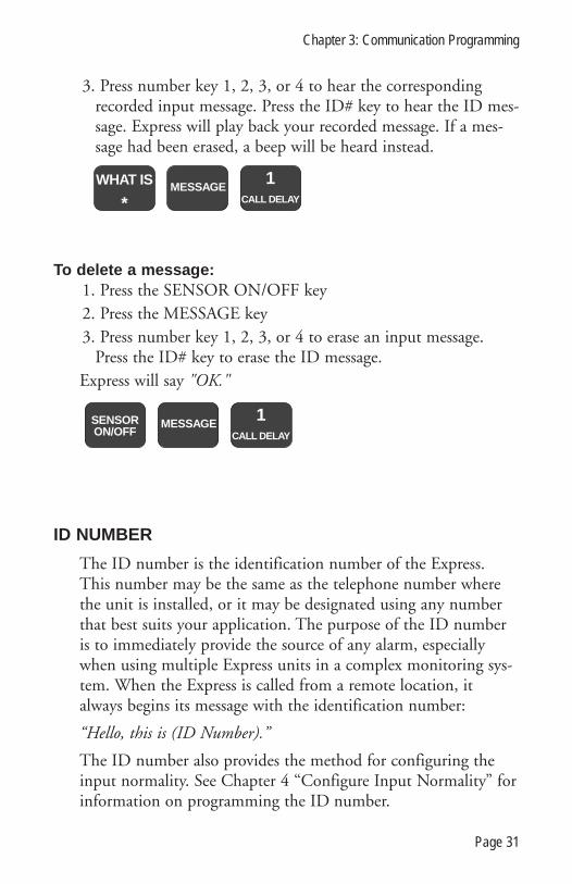
3. Press number key 1, 2, 3, or 4 to hear the correspondingrecorded input message. Press the ID# key to hear the ID mes-sage. Express will play back your recorded message. If a mes-sage had been erased, a beep will be heard instead.
To delete a message:1. Press the SENSOR ON/OFF key2. Press the MESSAGE key3. Press number key 1, 2, 3, or 4 to erase an input message.
Press the ID# key to erase the ID message.Express will say "OK."
ID NUMBER
The ID number is the identification number of the Express.This number may be the same as the telephone number wherethe unit is installed, or it may be designated using any numberthat best suits your application. The purpose of the ID numberis to immediately provide the source of any alarm, especiallywhen using multiple Express units in a complex monitoring sys-tem. When the Express is called from a remote location, italways begins its message with the identification number:
“Hello, this is (ID Number).”
The ID number also provides the method for configuring theinput normality. See Chapter 4 “Configure Input Normality” forinformation on programming the ID number.
1CALL DELAY
MESSAGESENSORON/OFF
1CALL DELAY
WHAT IS
*MESSAGE
Chapter 3: Communication Programming
Page 31

DIAL-OUT TELEPHONE NUMBERS
The Sensaphone Express can store up to eight 32-digit phonenumbers. These are the numbers that will be called during analarm dial-out. The numbers are dialed sequentially 1 through 8.Therefore, program the first number you want called as Phone#1, the second one as Phone #2, and so on. A pause, pound orasterisk can be added to the phone number to access differentphone and beeper systems. See Special Dialing.
To program the dial-out telephone numbers:1. Press the SET key2. Press the PHONE NUMBER key3. Select the Phone number (keys 1-8)Express will say “Enter number.”4. Enter the phone number using the number keys5. Press the ENTER keyExpress will say “OK.”
To interrogate a dial-out telephone number:1. Press the WHAT IS key2. Press the PHONE NUMBER key3. Select the Phone number (keys 1-8)Express will recite the number programmed. If there is no num-ber programmed, Express will say “No number.”
To delete a Phone number:1. Press the SET key2. Press the PHONE NUMBER key
PHONENUMBER
1CALL DELAY
WHAT IS
*
ENTEROUTPUT
(enter number)PHONE
NUMBERSET
#1
CALL DELAY
Sensaphone Express User’s Manual
Page 32

3. Select the Phone number (1-8) to eraseExpress will say “Enter number.”4. Press the ENTER keyExpress will say “OK.”
SPECIAL DIALING
Express has provisions for special dialing sequences. There arefour keys that represent special functions when used within aphone number. The SET key produces a # tone. The WHAT ISkey produces the * tone. The PAUSE key represents a two sec-ond pause in dialing. The CODE key instructs Express to waituntil the call is answered before continuing. These provisions aremainly for dialing out to a beeper or pager, or when the phonesystem requires dialing an access number to reach an outsideline.
The following is a typical scenario for dialing a pager:
SET PHONE 1
1 800 555 1212 CODE PAUSE 1 2 3 4 #
ENTER
Express will dial the pager number, wait for it to answer, pauseand then give 1234#.
NOTE: When interrogating a Phone Number, a PAUSE isrepresented as a beep, the asterisk (*) = 11, the pound (#) =12, and CODE = 14.
SET#
WHAT IS
*PAUSETONE CODE
ENTEROUTPUT
PHONENUMBER
SET#
1CALL DELAY
Chapter 3: Communication Programming
Page 33

TONE OR PULSE DIALING
Express can dial out in pulse or touch-tones. All numbers willbe called using the chosen dialing method. The default isTONE.
To program as either tone or pulse:1. Press the SENSOR ON/OFF key2. Press the TONE keyExpress will respond by saying “OFF” to indicate that tone dial-ing is off, or “ON” to indicate that tone dialing is on.
3. Repeat key sequence to change
RINGS UNTIL ANSWERThe rings until answer is the number of rings that must occurbefore Express answers the phone. This value can be from 1 to32. The default value is 1.
To program rings until answer:1. Press the SET key2. Press the RINGS keyExpress will say “Enter number.”
3. Using the number keys, enter a value4. Press the ENTER keyExpress will say “OK.”
To interrogate:1. Press the WHAT IS key
ENTEROUTPUT
SET#
0RINGS
TAD(enter number)
SENSORON/OFF
PAUSETONE
Sensaphone Express User’s Manual
Page 34

2. Press the RINGS keyExpress will recite the current value.
CALL DELAY TIME
The call delay time is the length of time Express will wait afteran alarm is recognized before it starts the dial-out sequence. Thisis only for the first call. To set delay time between calls, seeINTERCALL TIME. The default time is 30 seconds. The calldelay time can be programmed from 0 to 272 minutes 59 sec-onds.
The purpose of Call Delay is to allow time for personnel at theExpress unit’s installation site to respond to and cancel an alarmbefore dial out begins. During this time, the unit will audiblyrepeat its “alarm” message.
To program call delay time:1. Press the SET key2. Press the CALL DELAY keyExpress will say “Enter seconds.”
3. Enter the seconds using the number keys4. Press the ENTER keyExpress will say “OK.”
To interrogate:1. Press the WHAT IS key
2. Press the CALL DELAY key
ENTEROUTPUT
SET#
1CALL DELAY
(enter seconds)
WHAT IS
*0
RINGSTAD
Chapter 3: Communication Programming
Page 35

Express will recite the programmed time.
INTERCALL TIME
The Intercall Time is the programmable period of time theExpress unit waits to call subsequent telephone numbers.Intercall Time is activated only after alarm dial-out to the firsttelephone number fails to be acknowledged. This period canbe programmed from 0 to 272:59 minutes. The default IntercallTime is 30 seconds.
If an incoming telephone call is made to the unit duringIntercall Time (in between dialing of subsequent telephone num-bers to report an alarm), it will answer the incoming call andimmediately report any existing alarms. The manner in whichthe incoming call is answered depends upon whether or notTAD is enabled or disabled:
If TAD (Telephone Answering Device) is enabled, Rings UntilAnswer will be 1.
If TAD is disabled, Rings Until Answer will be 10.
To program intercall time:1. Press the SET key2. Press the INTERCALL TIME keyExpress will say, “Enter minutes.”
3. Using the number keys, enter the number of minutes4. Press the ENTER keyExpress will say “Enter seconds.”
5. Using the number keys, enter the number of seconds6. Press the ENTER keyExpress will say “OK.”
1CALL DELAY
WHAT IS
*
Sensaphone Express User’s Manual
Page 36

To interrogate:1. Press the WHAT IS key2. Press the INTERCALL TIME keyExpress will recite the programmed time.
CALL PROGRESS
Express monitors call progress when it dials out for an alarm. IfExpress encounters a busy signal or receives no answer after 8rings, the unit hangs up, waits the programmed intercall timeand then dials the next phone number.
When dialing some beeper/pager sevices, the line may beanswered before receiving a ringback. This may interfere withthe call progress detection and result in a failed call to the beep-er/pager. If this occurs, disable call progress detection.
To disable call progress detection:1. Press the Sensor On/Off key2. Press the Phone Number keyExpress will say “Off ” to indicate that call progress has beenturned off.
3. Repeat key sequence to change
PHONENUMBER
SENSORON/OFF
WHAT IS
*3
iNTERCALLTIME
ENTEROUTPUT
(enter seconds)ENTEROUTPUT
SET#
3iNTERCALL
TIME(enter minutes)
Chapter 3: Communication Programming
Page 37

VOICE REPETITIONS
The voice repetitions is how many times Express will repeat thealarm message per phone call when it dials out. This can be pro-grammed from 0 to 255 repetitions. The default value is 3 repe-titions.
To program the voice repetitions:1. Press the SET key2. Press the VOICE REPS keyExpress will say, “Enter number.”
3. Using the number keys, enter a value4. Press the ENTER keyExpress will say “OK.”
To interrogate:1. Press the WHAT IS key2. Press the VOICE REPS keyExpress will repeat the number programmed.
MAX CALLS
This value determines the maximum number of calls Expresswill make if none of the calls are acknowledged. If the numberof calls reaches this value, Express will automatically acknowl-edge the alarms and stop the dialout. The unit indicates it hasreached max calls by saying “warning message received by tele-phone number (ID number).” The max calls can be programmedfrom 0 to 255. The default is 100.
WHAT IS
*2
VOICE REPS
ENTEROUTPUT
SET#
2VOICE REPS
(enter number)
Sensaphone Express User’s Manual
Page 38

NOTE: If only one Phone Number is programmed, Expresswill dial a maximum of 15 times, regardless of the pro-grammed value of max calls.
To program max calls:1. Press the SET key2. Press the MAX CALLS keyExpress will say “Enter number.”
3. Using the number keys, enter a value4. Press the ENTER keyExpress will say “OK.”
To interrogate:1. Press the WHAT IS key2. Press the MAX CALLS keyExpress will recite the value of max calls.
TELEPHONE ANSWERING DEVICE COMPATIBILITY
Express can be used on the same telephone line as a telephoneanswering device, such as an answering machine, fax machine, ormodem. This feature allows you to call in to Express and bypassthe answering device.
To use TAD:1. Program Express’ RINGS UNTIL ANSWER to a greater
number than the rings until answer for your answering device.For example, Express RINGS = 5, device rings = 3.
2. Press the SENSOR ON/OFF key
WHAT IS
*4
MAX CALLS
ENTEROUTPUT
SET# (enter number)
4MAX CALLS
Chapter 3: Communication Programming
Page 39

3. Press the TAD key. Express will say “On.” (If Express says“Off ” repeat steps 2 & 3.)
4. Once TAD is on, allow the phone to ring once when you callthe unit and then hang up. Express recognizes that a call wasmade and activates a 30 second internal timer. This allows you30 seconds to call back the Express unit.
5. Call back within 30 seconds. Express will override theanswering device on this incoming call and answer the phoneon the first ring. Express resets the TAD timer after oneincoming call is received. If you want to call the unit again,you must repeat steps 4 and 5.
LISTEN-IN TIME
The listen-in time is the amount of time you can listen tosounds at the microphone site during a status call-in. The pro-grammable range is 0 to 255 seconds. The default setting is 15seconds.
To program the listen-in time:1. Press the SET key2. Press the LISTEN TIME keyExpress will say “Enter seconds.”
3. Using the number keys, enter the seconds4. Press the ENTER keyExpress will say “OK.”
ENTEROUTPUT
SET# (enter seconds)
8LISTEN TIME
SENSORON/OFF
0RINGS
TAD
Sensaphone Express User’s Manual
Page 40

To interrogate:1. Press the WHAT IS key2. Press the LISTEN TIME keyExpress will recite the time programmed.
SECURITY CODE
The security code is a 4-digit number that you program to pre-vent unauthorized access to Express’ programming. Locally,when the security code is employed, it will lock the keyboard,not allowing the programmed parameters to be changed. Youmay only interrogate the unit using the WHAT IS key. You mustunlock the keyboard by entering the security code to change theprogramming parameters.
For call-in access, the position of the REMOTE SECURITYPIN (see Chapter 6) determines whether the security code mustbe entered via touch-tone phone to obtain programming access.You may set the remote security pin so that Express will ignorethe code to allow access during a dial-in. Or, you may set theremote security pin to check the code when you call in. If youenter the correct code, you will gain access to Express to use thephone commands. If you enter the incorrect code, Express willhang up. You cannot program or change the security coderemotely. For an explanation of how to use the security codeduring a call in, see Chapter 5.
To program the security code / lock the keyboard:1. Press the SET key2. Press the CODE keyExpress will say “Enter code.”
WHAT IS
*8
LISTEN TIME
Chapter 3: Communication Programming
Page 41

3. Using the number keys, enter 4 digits4. Press the ENTER keyExpress will say “OK.”
To unlock the keyboard:1. Press the WHAT IS key2. Press the CODE keyExpress will say “Enter code.”
3. Using the number keys, enter your 4 digit code. (If you enterthe incorrect code, Express will say “Error.”)
4. Press the ENTER keyExpress will say “OK” if the correct code was entered.
NOTE: You may not interrogate the security code. TheWHAT IS key is used to unlock the keyboard when the cor-rect code is entered.
LOCAL MUTE
When Express dials out with an alarm, it recites the alarm mes-sage over the phone and at the monitor site. The local voicemute command allows you to mute the voice repetitions at themonitor site.
To locally mute Express:1. Press the SENSOR ON/OFF key2. Press the MUTE keyExpress will say “On” to indicate that the mute is on. It will say“Off ” to indicate when the mute is off.
ENTEROUTPUT
WHAT IS
*CODE (enter code)
ENTEROUTPUT
SET# CODE (enter code)
Sensaphone Express User’s Manual
Page 42

3. Repeat key sequence to change.
9ID#
STATUSMUTE
SENSORON/OFF
Chapter 3: Communication Programming
Page 43

Sensaphone Express User’s Manual
Page 44

CHAPTER 4: ALARM PROGRAMMING
This chapter explains the keyboard commands for the monitor-ing functions of Express. This includes:
� Enable/disable inputs� Configure input normality—The ID number� Input recognition time� Temperature scale� Temperature limits� Enable/disable temperature inputs� Temperature recognition times� Temperature calibration� AC power monitoring enable/disable� AC Power recognition time
ENABLE/DISABLE INPUTS
This function allows you to enable or disable an input (1-4) todial out during an alarm. An enabled input will respond to analarm and allow dial-out. A disabled input will not initiate adial-out. This command is useful while you are wiring yourinputs or at any other time you would like the alarms to beignored. The default setting for all inputs is enabled (on).
To enable/disable inputs:1. Press the SENSOR ON/OFF key2. Press the corresponding number key (1-4) of the input you
want to enable/disableExpress will say “Off ” to indicate disabled or “On” to indicateenabled.
3. Repeat key sequence to change
1CALL DELAY
SENSORON/OFF
Chapter 4: Alarm Programming
Page 45

CONFIGURE INPUT NORMALITY
Inputs must be configured as normally open or normally closed.The default for all inputs is open. See Chapter 2 for an explana-tion on wiring inputs. Configuring the input normality is doneby setting the unit’s ID number. When the ID number is set,Express looks at the four inputs and establishes the presentopen/closed state as normal. Any change from that normal stateis an alarm. The ID number is also usually programmed as theunit phone number. This number is recited during a statusreport and alarm dial-out report.
To set the status of the inputs as normal:1. Disable the input (see above)2. Wire the input3. Press the SET key4. Press the ID# keyExpress will say, “Enter number.”
5. Using the number keys, enter the unit’s phone number6. Press the ENTER keyExpress will say “OK” if the number was accepted.
7. Enable the inputThe inputs are now considered normal. If a normally closedinput becomes open, an alarm will occur. If a normally openinput becomes closed, an alarm will occur.
To interrogate the ID number and system status:1. Press the WHAT IS key2. Press the ID# keyExpress will say “Hello, this is ...” followed by a recitation of theprogrammed ID# and a status report.
ENTEROUTPUT
9ID#
STATUSMUTE
SET# (enter number)
Sensaphone Express User’s Manual
Page 46

INPUT RECOGNITION TIME
The input recognition time is the length of time an input musthave an alarm continuously before Express will recognize thecondition. If an alarm exists and then clears within the recogni-tion time, it is never considered an alarm. This is useful to pre-vent nuisance dialouts for momentary alarm conditions or onself-correcting equipment. Each input can be programmed witha different recognition time. The default recognition time is 3seconds. You may program the recognition time from 0 secondsto 272 minutes.
To program the recognition time:1. Press the SET key2. Press the REC TIME key3. Press the corresponding input key (1-4)Express will say “Enter minutes.”
4. Using the number keys, enter minutes5. Press the ENTER keyExpress will say “Enter seconds.”
6. Using the number keys, enter seconds7. Press the ENTER keyExpress will say “OK.”
To interrogate the recognition time:1. Press the WHAT IS key2. Press the REC TIME key
ENTEROUTPUT
ENTEROUTPUT
(enter seconds)SET
#1
CALL DELAY(enter minutes)
7REC TIMEPOWER
9ID#
STATUSMUTE
WHAT IS
*
Chapter 4: Alarm Programming
Page 47

3. Press the corresponding input key (1-4)Express will recite the programmed recognition time for thatinput.
TEMPERATURE SCALE
Express can monitor temperature in degrees Fahrenheit ordegrees Celsius. The default setting is Fahrenheit. NOTE:When switching from Fahrenheit to Celsius or vice versa,remember to reprogram your temperature limits accordingly.
To program the temperature scale:1. Press the SENSOR ON/OFF key2. Press the TEMP keyExpress will either say “On” to indicate Celsius, or “Off ” to indi-cate Fahrenheit.
3. Repeat key sequence to change
TEMPERATURE LIMITS
The following keyboard commands are used to set the low andhigh temperature limits. The default settings are Low Temp =10° and High Temp = 100°. The range of programming is -60°to 300°F(-50° to 150°C). Note: the sensor included withExpress has a sensory range of only -60° to 175°F (-50° to 80°).
To program the low temperature limit:1. Press the SET key2. Press the LOW TEMP key
SENSORON/OFF TEMP
1CALL DELAY
WHAT IS
*7
REC TIMEPOWER
Sensaphone Express User’s Manual
Page 48

Express will say “Enter number.”
3. Using the number keys, enter the low temperature number.If you want the number to be negative, press the PAUSE keyfollowed by the number.
4. Press the ENTER keyExpress will say “OK.”
To program the high temperature limit:1. Press the SET key2. Press the HIGH TEMP keyExpress will say “Enter number.”
3. Using the number keys, enter the high temperature limit. Ifyou want the number to be negative, press the PAUSE key fol-lowed by the number.
4. Press the ENTER keyExpress will say “OK.”
To interrogate the temperature limits:1. Press the WHAT IS key2. Press the LOW TEMP key to check the low temperature
limit. Press the HIGH TEMP key to check the high tempera-ture limit.
WHAT IS
*5
LOW TEMP
6HIGH TEMP
(or)
ENTEROUTPUT
SET# (enter number)
6HIGH TEMP
ENTEROUTPUT
SET# (enter number)
5LOW TEMP
Chapter 4: Alarm Programming
Page 49

ENABLE/DISABLE TEMPERATURE INPUT
This feature allows you to enable or disable the temperatureinput to dialout for a temperature alarm. When the temperatureinput is enabled, it will cause a dialout for an alarm. If it is dis-abled, it will not cause a dialout. It is helpful to disable the tem-perature inputs while wiring thermistors and setting limits toprevent tripping an alarm.
To enable/disable the low temperature alarm:1. Press the SENSOR ON/OFF key2. Press the LOW TEMP keyExpress will say “On” to indicate that the low temperature alarmis enabled, or “Off ” to indicate the input is disabled.
3. Repeat key sequence to change
To enable/disable the high temperature alarm:1. Press the SENSOR ON/OFF key2. Press the HIGH TEMP keyExpress will say “On” to indicate that the high temperature alarmis enabled, or “Off ” to indicate the input is disabled.
3. Repeat key sequence to change
TEMPERATURE RECOGNITION TIME
The temperature recognition time is the length of time that alow or high temperature alarm must exist continuously beforeExpress will recognize it as an actual alarm and start an alarm
SENSORON/OFF
6HIGH TEMP
SENSORON/OFF
5LOW TEMP
Sensaphone Express User’s Manual
Page 50

dialout. If an alarm exists and then clears within the recognitiontime, it is never considered an alarm. The default setting is 3seconds. You may set the recognition time from 0 seconds to272 minutes.
To program the low temperature recognition time:1. Press the SET key2. Press the REC TIME key3. Press the LOW TEMP keyExpress will say “Enter minutes.”
4. Using the number keys, enter the number of minutes5. Press the ENTER keyExpress will say “Enter seconds.”
6. Using the number keys, enter the number of seconds7. Press the ENTER keyExpress will say “OK.”
To program the high temperature recognition time:1. Press the SET key2. Press the REC TIME key3. Press the HIGH TEMP keyExpress will say “Enter minutes.”
4. Using the number keys, enter the number of minutes5. Press the ENTER keyExpress will say “Enter seconds.”
6. Using the number keys, enter the number seconds7. Press the ENTER keyExpress will say “OK.”
ENTEROUTPUT
ENTEROUTPUT
(enter seconds)SET
# (enter minutes)7
REC TIMEPOWER
5LOW TEMP
Chapter 4: Alarm Programming
Page 51

To interrogate the low or high temperature recognition time:1. Press the WHAT IS key2. Press the REC TIME key3. Press LOW TEMP key for the low temperature recognition
time. Press the HIGH TEMP key for the high temperaturerecognition time.
Express will recite the programmed low or high temperaturerecognition time.
TEMPERATURE CALIBRATION
Due to tolerance variations or other factors, you may want toprogram an offset to calibrate the temperature input. The offsetcan be from 1 to 15, or -1 to -15. Setting a positive number willadd that number to the temperature reading. Setting a negativenumber will subtract.
To calibrate the temperature input:1. Press the SET key2. Press the PAUSE keyExpress will say “Enter number.”
2a. To program a negative number (i.e. -7), press the PAUSEkey again.
3. Enter the number4. Press the ENTER keyExpress will say “OK.”
WHAT IS
*(or)
7REC TIMEPOWER
5LOW TEMP
6HIGH TEMP
ENTEROUTPUT
ENTEROUTPUT
(enter seconds)SET
# (enter minutes)7
REC TIMEPOWER
6HIGH TEMP
Sensaphone Express User’s Manual
Page 52

To interrogate the present calibration:1. Press the WHAT IS key2. Press the PAUSE keyExpress will recite the programmed temperature calibration.
AC POWER MONITORING ENABLE/DISABLE
Express monitors AC power failure. This command enables ordisables the power failure detection. When enabled, Express willmonitor power and dial out if a valid failure occurs. When dis-abled, Express will not dial-out for a power alarm. The defaultsetting is ON.
To enable/disable the power input:1. Press the SENSOR ON/OFF key2. Press the POWER keyExpress will say “On” to indicate that the power input is enabled;OR, Express will say “Off ” to indicate that the power input isdisabled.
3. Repeat key sequence to change
SENSORON/OFF
7REC TIMEPOWER
WHAT IS
*PAUSETONE
ENTEROUTPUT
SET#
PAUSETONE
(enter number)
Chapter 4: Alarm Programming
Page 53

POWER RECOGNITION TIME
The power recognition time is the length of time that a powerfailure must exist continuously before Express will recognize it asan actual alarm and start the dial-out sequence. The default set-ting is 5 minutes. You may program the power recognition timefrom zero seconds to 272 minutes.
To program the power recognition time:1. Press the SET key2. Press the REC TIME key3. Press the POWER keyExpress will say “Enter minutes.”
4. Using the number keys, enter the number of minutes5. Press the ENTER keyExpress will say “Enter seconds.”
6. Using the number keys, enter the number of seconds7. Press the ENTER keyExpress will say “OK.”
To interrogate the power recognition time:1. Press the WHAT IS key2. Press the REC TIME key3. Press the POWER keyExpress will recite the power recognition time.
WHAT IS
*7
REC TIMEPOWER
7REC TIMEPOWER
ENTEROUTPUT
(enter seconds)ENTEROUTPUT
SET# (enter minutes)
7REC TIMEPOWER
7REC TIMEPOWER
Sensaphone Express User’s Manual
Page 54

EXIT DELAY
The Exit Delay feature provides a temporary time period duringwhich the unit will disregard an alarm condition. This is typical-ly used in security applications where you may be monitoring adoorway, and in the process of exiting the building you must gothrough the monitored doorway. The Exit Delay will temporari-ly disable the input while you are leaving and then re-enable theinput automatically. The Exit Delay is 20 seconds.
To start the Exit Delay:1. Press the WHAT IS key2. Press the STATUS keyExpress will say “Hello, this is ...” followed by the ID# and a sta-tus report. Any alarms that occur during this recitation will beautomatically cleared at the end of the status report. Any alarmsthat still exist will be automatically acknowledged and will notinitiate dialout.
9ID#
STATUSMUTE
WHAT IS
*
Chapter 4: Alarm Programming
Page 55

Sensaphone Express User’s Manual
Page 56

CHAPTER 5: CALL-IN COMMANDS
The following three functions are call-in commands. Thismeans that to utilize them, you must call Express to execute thecommand. These features are: alarm acknowledgment, statusreport and the phone commands. Alarm acknowledgment canbe accomplished and the status report can be obtained by pulse(rotary) or touch-tone phone. To use the phone commands, youmust have a touch-tone phone.
ALARM ACKNOWLEDGMENT
When Express dials out with an alarm message, it will requestacknowledgment before hanging up. Acknowledgment indicatesto Express that the alarm message has been received. Uponacknowledgment, Express will cease the dial out sequence. Thered LED for the alarm will stop blinking and glow steadily untilthe alarm condition has been resolved.
There are four ways that an alarm can be acknowledged: locally,by code, by call-in code acknowledgment and callback automaticacknowledgment.
1. Local alarm acknowledgment: On the Express keyboard isthe ALARM CANCEL key. When an alarm exists, press theALARM CANCEL key to acknowledge the alarm. Express willsay “OK” and the red LED for that input will stop blinking.
2. Code acknowledgment: This method can only be used on atouch-tone phone. At the end of the alarm dial out message,Express requests acknowledgment that the message has beenreceived by saying: “Please acknowledge.” You have 10 secondsto enter the code “555.”
To do this, press the number key 5 on the touch-tone phonekeypad three times. Express will say: “OK. Have a good day.”The unit will then hang up.
Chapter 5: Call-In Commands
Page 57
If you did not enter a correct code within 10 seconds, Expresswill say: “Have a good day.” Express will then hang-up. Thealarm has not yet been acknowledged.
3. Call-in acknowledgment: This feature allows you to call-into Express from a touch-tone phone and enter the acknowledg-ment code. To do this, call Express back after receiving an alarmdial out message. When Express answers, you will receive thealarm dial out message followed by a request for alarm acknowl-edgment: “Please acknowledge.” You have 10 seconds to enterthe code “555” by pressing the corresponding key on the touch-tone phone keypad.
If the correct code is entered within 10 seconds, Express will say“OK. Have a good day,” to indicate that the alarm was acknowl-edged. The dial out sequence is stopped. The red LED willstop blinking and glow steadily until the alarm condition isresolved.
If you did not enter a correct code within 10 seconds, Expresswill say: “Have a good day,” and then hang up.
4. Callback acknowledgment: This method is controlled bythe configuration of pin #2 on the Express circuit board, seeChapter 6. When the shunt on pin #2 is in the on position,simply calling Express will acknowledge an existing alarm. Youmay call from either a touch-tone or pulse (rotary) phone toacknowledge the alarm.
To use, call Express. The unit will recite the dial out alarm mes-sage and then say: “Alarm OK. Have a good day,” to indicatethat the alarm has been acknowledged.
STATUS REPORT
The status report feature allows you to call-in to Express andcheck the temperature and power status. If any alarm conditionsexist, the alarm message will be recited. You can also listen in toon-site sounds and access the unit programming via phone com-mands.
Sensaphone Express User’s Manual
Page 58

NOTE: If you happen to call Express during the alarm dialout sequence (when an alarm condition exists but is not yetacknowledged) you will not receive a status report. Expresswill consider the call as either a call-in code acknowledgmentor callback acknowledgment (see above).
To obtain a status report, call Express. The following is anexample of what the unit will recite when it answers:
This is 555-3833 (unit phone number).This is the equipment room located in Building One North(ID message).The temperature is 70 degrees (current temperature).The electricity is on (power status).No alarm exists (alarm status).Listen for 10 seconds (user-programmed listen-in time).(on-site sound monitoring for 10 seconds)OK.(10-second wait for phone command access)Have a good day. (hangs up)
If an alarm condition has been acknowledged but still exists,Express will recite that input’s recorded alarm message. Below isan example of a status report with an acknowledged smokealarm.
This is 555-3833.This is the equipment room located in Building One North.The temperature is 70 degrees.The electricity is on.Smoke has been detected. A fire emergency is possible(recorded alarm message).Listen for 10 seconds.(on-site sound monitoring)OK.(10-second wait for phone command access)Have a good day.(hangs up)
Chapter 5: Call-In Commands
Page 59

If the power is out but has not reached the recognition time tobe considered an alarm, Express will recite the following messageduring the status report:
“... The temperature is 70 degrees.The electricity is off.No alarm exists.Listen for ...”
If the power is out and has reached the recognition time to beconsidered an alarm, Express will recite:
“... The temperature is 70 degrees.The electricity is off.Listen for ...”
Access to programming: The unit allows you to access andchange some of your programming remotely using a touch-tonetelephone. To initiate access, call the unit and listen to the entirestatus report. Towards the end of the report the unit will say“OK.” Press any key on your touch tone telephone within 10seconds and the unit will again say “OK” and enter remote pro-gramming mode. The commands for this mode are described inthe following section, Phone Commands.
Remote programming access may be restricted by using thesecurity code. This code is the same as the one for keypadsecurity. You may, however, independently enable or disableremote security code requirements by moving one of the shuntsdescribed in Chapter 6.
If a security code has been programmed and the remote securityoption is enabled, the unit will first ask you to enter the securitycode before allowing remote access. Upon correct entry of thesecurity code the unit will say “OK.”
You may now program the Express unit remotely.
NOTE: You cannot permanently unlock the security coderemotely. You must do so on the local keypad only (seeChapter 3).
Sensaphone Express User’s Manual
Page 60

PHONE COMMANDS
You can record, interrogate and program Express remotely usinga touch-tone phone. This is accomplished through the phonecommands. You may perform the following functions via touch-tone phone:
� What is:Alert message 1Alert message 2Alert message 3Alert message 4ID message
� Record:Alert message 1Alert message 2Alert message 3Alert message 4ID message
� Turn ON/OFF OUTPUT
� Enable/Disable:Alerts 1-4Low TempHigh TempPower
To use the phone commands, call Express. You will receive a sta-tus report. After the listen-in time, Express will say “OK.” PressANY KEY within 10 seconds to access the phone commandmode. If this is done, Express will say “OK.” You now have 30seconds to enter a key command before Express will hang up. Ifyou do not press a key within 30 seconds Express will say “Havea good day,” and disconnect. More than one command can beentered. The 30 second time out restarts at the end of eachcommand.
Chapter 5: Call-In Commands
Page 61

To listen to a recorded alarm message:1.Press the * key on your phone2.Press the corresponding number key: 1-4, or
Press number key 9 to listen to an ID message.Express will recite the recorded message
To record a message remotely:1. Press the # key2. For an alarm message, press the corresponding number key:
1-4.To record the ID message, press number key 9.3. After the beep, say your message clearly. The alarm message
can be up to 8 seconds long. The ID message can be up to10.5 seconds long.
Express will beep at the end of the time allotment.
To turn ON/OFF the output:1. The output (pin #6) must be in the ON position for manual
control. See Chapter 6 for explanation of pin #6.2. To turn the output ON, press O (number 6) then N (num-
ber 6)Express will say “On.”
3. To turn the output OFF, press O (number 6) then F (num-ber 3)
Express will say “Off.”If pin #6 is in the off position for automatic control, Express
will say “Error” if you try to turn the output on or off.
To enable or disable an input:1. Press the number key 0.2. Press number key 1-4 to enable/disable alert 1-4Press number key 5 to enable/disable Low TempPress number key 6 to enable/disable High TempPress number key 7 to enable/disable Power
Sensaphone Express User’s Manual
Page 62

3. Repeat key sequence to changeExpress will say “On” to indicate the input is enabled or “Off ” to
indicate the input is disabled.
Chapter 5: Call-In Commands
Page 63

Sensaphone Express User’s Manual
Page 64

CHAPTER 6: USER OPTIONS
The following are user options designed to increase the versatili-ty for Express’s programming features. These options areaccessed by setting shunts on pins on the circuit board. Thepins are located to the right of the ON/OFF switch. There areseven user options available that are activated by placing theshunt in the ON or OFF position on the pin. This allows youto further customize Express to dial out and monitor accordingto your application. These options include:
� Tone/Pulse Acknowledgment� Remote Security� Automatic Redial on Busy� Thermistor Alternative� Output Control� Dialing Options
When the shunt is in the left position, it is considered off.
When the shunt is in the right position, it is considered on.
To move a shunt:1. Using a pair of narrow-tipped or needlenose pliers, pull the
shunt up off the pins.2. Move the shunt to the on or off position3. Carefully push the shunt back into place.
Shunt in OFF position:
Shunt in ON position:
Chapter 6: User Options
Page 65

TONE/PULSE ACKNOWLEDGMENT
PIN#2: This feature enables you to acknowledge an alarm dial-out call from a pulse (rotary) phone. Use only when phonesreceiving the calls cannot use touch-tone. When the shunt is inthe off position, alarm calls can only be acknowledged from atouch-tone phone by entering the code “555.”
When the shunt on pin #2 is in the on position, alarm calls canbe acknowledged by a pulse phone in addition to a touch-tonephone. Acknowledgment by pulse phone is accomplished bysimply calling the unit back after receiving an alarm call. WhenExpress answers the callback, the alarm(s) will be acknowledged.See diagram.
REMOTE SECURITY
PIN #3: This option is used to control remote access to Express’programming via telephone by enabling or disabling the securitycode (see Chapter 3). When the remote security code is enabled,the unit will prompt the user to enter the security code beforeprogramming access is granted. The remote security shunt canbe used to enable or disable the security code during a call-in.
When the shunt on pin #3 is in the off position, the securitycode is disabled during a call-in. Interrogation and program-ming by the phone commands are accessible without knowingthe security code.
When the shunt on pin #3 is in the on position and the securitycode is programmed , that code is needed to access programmingwith the phone commands.
Touch-Tone acknowledgment only:
Pulse/Tone callback acknowledgment:
Sensaphone Express User’s Manual
Page 66

REDIAL ON BUSY
PIN #4: This feature determines what Express will do when itencounters a busy signal during an alarm dial-out. Dependingon the position of this shunt, Express will either hang up andproceed to dial the next phone number, or it will dial the busyphone number again before going on to the next number.
This feature is set by moving shunt on pin #4 on the circuitboard. When the shunt is in the off position, Express will hang-up if it encounters a busy signal and proceed with calling thenext phone number.
When shunt on pin #4 is in the on position, Express will dialthe phone number again if it encounters a busy signal. If thenumber is still busy, Express will hang up and proceed with thenext phone number.
THERMISTOR ALTERNATIVE
PIN #5: Two different kinds of thermistors are compatible withExpress for temperature monitoring — the 2.8K thermistor andthe 10K thermistor. A 2.8K thermistor is included with Express.
Hang up on busy:
Dialback on busy:
Remote Security code Disabled:
Remote Security code Enabled:
Chapter 6: User Options
Page 67

However, you may use the 10K sensor as an alternate. Youwould use the 10K thermistor to get a broader range of tempera-ture monitoring, particularly the warmer temperatures. Also, the10K thermistor is available in a variety of special packages forspecific locations for temperature sensing, indoor/outdoor, etc.See Appendix B for specifications.
To use the alternate 10K thermistor, you must switch the shunton pin #5 on the circuit board. When the shunt is in the offposition (to the left), the board is configured to use the normal(2.8K) sensor. This is the factory default. To use the 10K ther-mistor move the shunt to the on position. See diagram below.
OUTPUT CONTROL
PIN #6: This pin allows you to control the output in one oftwo ways: automatically or manually. Automatic output controlturns on the output when an alarm occurs on any of the inputs.The output is then turned off when the alarm is acknowledged.For manual control, you call into the unit and control the out-put via phone command. When the shunt is in the off position,it is configured for automatic control. Move the shunt to the onposition for manual (phone command) control.
Automatic Output Control:
Manual Output Control:
Normal--2.8K Thermistor:
Alternate--10K Thermistor:
Sensaphone Express User’s Manual
Page 68

DIALING PATTERN
PINS #7 AND #8: Dialing pattern is a calling process thatallows you to prioritize your phone list by assigning dial-out forcertain alarms to Phone #1 only. There are four dialing choicesavailable with this feature. Each allows you to program Phone#1 to be called only on specific alarms. Choice 1 enables dial-out to all Phone numbers for all alarms. Choice 2 enables dial-out to Phone #1 for input alarm #1. Choice 3 enables dial-outto Phone #1 for temperature alarms only. Choice 4 enables dial-out to Phone #1 for a power alarm only. Dialing choices are setby moving the shunts on pins #7 and #8. When a shunt is tothe left, it is in the off position. When it is moved to the right,it is in the on position. For each dialing choice below, there aretwo diagrams. One is a chart illustrating the dial-out sequencefor each option. The second diagram shows the shunt configura-tions for each option.
Key for Dialout Charts:An ‘x’ indicates that a phone number is dialed for an inputalarm.1-4 = dry contact inputsTL = temperature lowTH = temperature highPW = power
DIALING CHOICE 1:This choice enables dial-out for all alarms to all Phone numbers.All 8 Phone numbers will be called for alarms 1-4, Temp Low,Temp High, and power failure. To program dialing choice 1,move shunts for pins #7 and #8 to the off position.
Chapter 6: User Options
Page 69

Dialout Chart - Choice 1
Shunt Configuration - Choice 1
DIALING CHOICE 2:This choice enables dial-out to Phone #1 for alarm 1 only.Phone #2-8 will be called for alarms 2-4, Temp Low, TempHigh, and power failure. To program dialing choice 2, moveshunt on pin #7 to the off position. Move shunt on pin #8 tothe on position.
Dialout Chart - Choice 2PHONE # 1 - 8
INP
UT
S
1 2 3 4 5 6 7 8
01
02
03
04
TL
TH
PW
x x x x x x x
x x x x x x x
x x x x x x x
x x x x x x xx x x x x x x
x x x x x x x
x
Shunt #7:
Shunt #8:
PHONE # 1 - 8
INP
UT
S
1 2 3 4 5 6 7 8
01
02
03
04
TL
TH
PW
x x x x x x x
x x x x x x x
x x x x x x x
x
x x x x x x x
x x x x x x x
x x x x x x x
x
x x x x x x x
x
xx
x
x
Sensaphone Express User’s Manual
Page 70

Shunt Configuration - Choice 2
DIALING CHOICE 3:This choice enables dial-out to Phone #1 for Temp Low andTemp High alarms only. Phone #2-8 will be called for alarms 1-4 and power failure. To program dialing choice 3, move shunton pin #7 to the on position. Move shunt on pin #8 to the offposition.
Dialout Chart - Choice 3
Shunt Configuration - Choice 3
Shunt #7:
Shunt #8:
PHONE # 1 - 8
INP
UT
S
x
1 2 3 4 5 6 7 8
01
02
03
04
TL
TH
PW
x x x x x x x
x x x x x x x
x x x x x x x
x x x x x x x
x
x x x x x x x
Shunt #7:
Shunt #8:
Chapter 6: User Options
Page 71

DIALING CHOICE 4:This choice enables dial-out to Phone #1 for a power failurealarm only. Phone #2-8 will be called for alarms 1-4, Temp Lowand Temp High. To program dialing choice 4, move the shuntson pins #7 and #8 to the on position.
Dialout Chart - Choice 4
Shunt Configuration - Choice 4
Shunt #7:
Shunt #8:
PHONE # 1 - 8
INP
UT
S
1 2 3 4 5 6 7 8
01
02
03
04
TL
TH
PW
x x x x x x x
x x x x x x x
x x x x x x x x x x x x x x
x x x x x x x
x x x x x x x
x
Sensaphone Express User’s Manual
Page 72
CHAPTER 7: THE OUTPUT
Express has one relay output that can be controlled automaticallyor manually. Pin #6, located to the right of the ON/OFF switchon the circuit board, is used to determine how the output will becontrolled. See Chapter 6 for more information on Pin #6.
AUTOMATIC CONTROL
For automatic control, Express will switch on the device wired tothe relay output whenever an alarm occurs on any of the inputs.When the alarm is acknowledged (NOT when the condition iscorrected), the output is switched off.
To have the output controlled automatically, you must positionthe shunt on pin #6 to the left (OFF position).
MANUAL CONTROL
You may manually control the output from the local keyboard,or remotely by touch-tone phone. To allow the output to becontrolled manually, you must position Shunt #6 to the right(ON position).
To switch the output locally:1. Press the SENSOR ON/OFF key2. Press the OUTPUT keyExpress will say either "On" or "Off." Repeat the steps tochange.
To switch the output remotely:You must use the phone commands to manually switch the out-put remotely. To do this, call into Express using a touch-tonephone. First, you will receive a status report. After the listen-intime, Express will say “OK.” Press ANY KEY on the touch-tonekeypad within 10 seconds to access the phone command mode.If this is done, Express will say “OK” again. You now have 30
Chapter 7: The Output
Page 73

seconds to enter a key command before Express will hang up. Ifyou do not press a key within 30 seconds, Express will say “Havea good day,” and disconnect.
1. To turn the output on, press O (number 6), then N (number6). Express will say “On.”
2. To turn the output off, press O (number 6), then F (number3). Express will say “Off.”
If Pin #6 is set in the off position for automatic control, Expresswill say “Error” if you try to turn the output on or off manually.
For more information on other phone commands, see Chapter5.
POWER LIMITATIONS
Express has two power supplies (5V & 12V) available to poweryour external sensors or output devices. The maximum currentavailable is 100mA total. This means that the sum of the cur-rents from each supply cannot exceed 100mA.
Maximum switching capacity of the relay output:
2A at 120VAC2A at 30VDC
EXAMPLE WIRING
12V device using Express power:
Sensaphone Express User’s Manual
Page 74
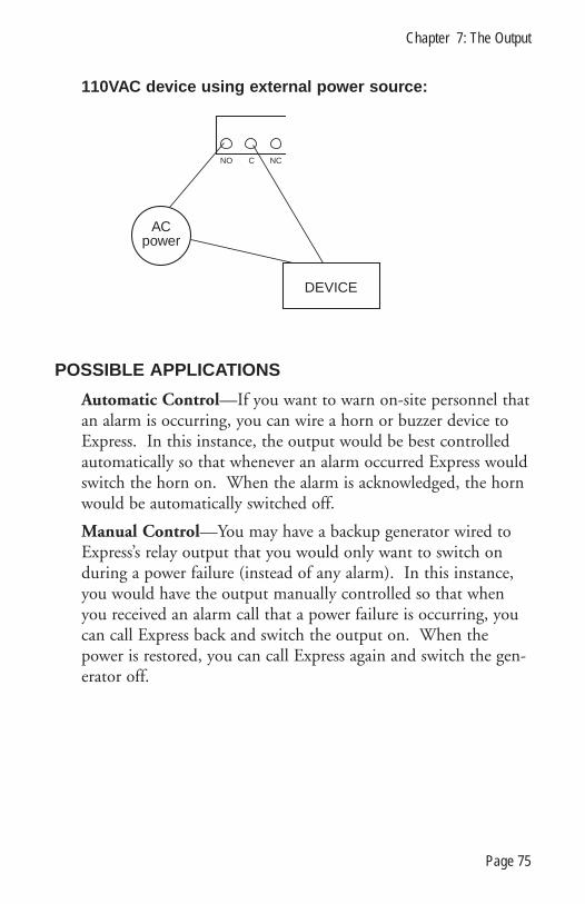
110VAC device using external power source:
POSSIBLE APPLICATIONS
Automatic Control—If you want to warn on-site personnel thatan alarm is occurring, you can wire a horn or buzzer device toExpress. In this instance, the output would be best controlledautomatically so that whenever an alarm occurred Express wouldswitch the horn on. When the alarm is acknowledged, the hornwould be automatically switched off.
Manual Control—You may have a backup generator wired toExpress’s relay output that you would only want to switch onduring a power failure (instead of any alarm). In this instance,you would have the output manually controlled so that whenyou received an alarm call that a power failure is occurring, youcan call Express back and switch the output on. When thepower is restored, you can call Express again and switch the gen-erator off.
ACpower
DEVICE
NO NCC
Chapter 7: The Output
Page 75

Sensaphone Express User’s Manual
Page 76

CHAPTER 8: PROGRAMMING SUMMARY
This section is intended to help you understand the commandsand organize your programming. It is advisable to disable theinputs while programming to avoid a dialout if you accidentallytrip an alarm. Remember to enable the inputs after program-ming has been completed. The following is a summary of thepossible programming commands. Refer to the programmingchapters—3 and 4—for explanation on how to use each com-mand.
MONITORING FUNCTIONS
1. Disable inputs 1-4. This action will allow you to wire andset the dry contact inputs without tripping an alarm dialout.
2. Wire inputs 1-4.
3. Configure inputs as normally opened or normally closed.This command determines what will be the normal or alarm sta-tus for each input 1-4. When you set the ID number, the pres-ent open/closed state of your sensors will be considered normal.For example, if you have input 1 wired as a closed input, settingthe ID number will make it normally closed. If the inputshould be opened, an alarm will result.
4. Set input recognition time. This command determines thelength of time an alarm condition must exist before it is consid-ered an alarm. It helps you to minimize alarm dialouts formomentary and/or self-correcting alert incidents. For example,input 1 monitors fluid depth in a brewing vat. Liquid is period-ically poured into and drained from the vat. This action causesthe liquid to splash above the high fluid mark, resulting in analarm. However, the fluid quickly settles, just as personnel arriveat the site to siphon the dangerous excess. Setting the recogni-tion time for input 1 to 5 minutes would allow the liquid to sta-bilize, preventing a false alarm.
Chapter 8: Programming Summary
Page 77

5. Enable inputs 1-4. The inputs are now operational andmonitoring chosen conditions.
6. Disable temperature inputs. This will allow you to deter-mine Fahrenheit/Celsius, set limits and recognition times with-out causing an alarm dialout.
7. Determine temperature scale. Express has the capability tomonitor in Fahrenheit or Celsius. You should determine thetemperature scale before setting limits so that the temperaturereadings will make sense in your application.
8. Set low and high temperature limits. The range of theselimits depends directly on the temperature scale you chose (°F or°C) and the type of thermistor wired (2.8K or 10K).
With the 2.8K thermistor (included) the range is:-60°F to 175°F-50°C to 80°C
With a 10K thermistor (optional) the maximum* range is:-60°F to 300°F-50°C to 150°C
*Note: The range may be less depending on the sensor used.It is extremely important to choose the appropriate temperaturescale for your application and to properly configure the thermis-tor before setting limits. Meaningless temperature readings andalarms will result otherwise.
9. Temperature recognition times. This command determinesthe length of time a low or high temperature condition mustexist before Express recognizes it as an alarm. This will preventdialouts from occurring for momentary and/or self-correctingtemperature alerts.
10. Enable temperature inputs. Express is now temperatureoperational.
11. Enable or disable AC power monitoring. Express is capa-ble of monitoring AC power failure. This feature is built-in, noexternal wiring is required. You can enable or disable the power
Sensaphone Express User’s Manual
Page 78

detection. When enabled, Express will dial out for a power fail-ure. When disabled, Express will not dial out if a power failureoccurs. The default for this parameter is ENABLED.
12. Power recognition time. This is the length of time apower failure condition must exist before Express considers it analarm. This feature helps eliminate dialouts during power blipsor minor brownouts.
COMMUNICATIONS FUNCTIONS
Express is now prepared for alarm monitoring. Next, you mustprogram your alarm voice messages, Phone numbers, and relateddialing specifications.
1. Voice messages. Express’s unique digital speech technologyallows you to record your own voice for the 4 input alarm mes-sages and an ID message. You have 8 seconds per message foreach of the 4 input messages, and 10.5 seconds for the ID mes-sage. You can rerecord your messages as often as you wish.Messages may also be recorded remotely over a touch-tonephone. Messages are stored in nonvolatile memory to preventloss during a power failure or storage.
When recording, speak clearly. This is important locally andremotely. Hold the microphone about 6 inches from yourmouth. You may have to experiment to see what voice levelrecords best for you.
2. Dialout telephone numbers. Express can dial up to eight32-digit phone numbers. These phone numbers are dialedsequentially, so program the first number you want called asPhone #1, the second as Phone #2, etc.
You can also incorporate a pause, pound, or asterisk into thephone number for special dialing circumstances. For example,Express has the capability to call out to a beeper. The desiredresult when calling a beeper is: 1) Express dials the phone num-ber, 2) a beeper service will answer, 3) the service will look fordigits to send to the beeper.
Chapter 8: Programming Summary
Page 79
3. Tone or pulse dialing. Express’ phone numbers can bedialed out in either touch-tones or pulse depending on your lineservice. This parameter programs all 8 Phone numbers as toneor pulse. The default is TONE.
4. Rings until answer. This parameter determines how manytimes Express will allow the phone to ring before answering. Forexample, if you set this to 4, Express will wait 4 rings and thenanswer. This feature is also used in conjunction with theTelephone Answering Device (TAD) compatibility.
5. TAD compatibility. Express can operate on the same phoneline as other telephone answering devices such as a modem oranswering machine. To use this feature, program Express ringsuntil answer to a larger number than the other answeringdevice’s rings. For example, Express and an answering machineare on the same phone line. You program the answeringmachine to answer on the 3rd ring. Set Express to answer onthe 5th ring. When you call Express to obtain a status report,you will want to bypass the answering machine. To do this,allow the phone to ring once, hang up, and call again. On thesecond call Express will override the answering machine byanswering on the first ring.
6. Call delay time. This is the amount of time Express willwait after an alarm is recognized before it starts the dialoutsequence. NOTE: This feature is different from the inputrecognition times. Recognition time is the amount of timeExpress waits to declare an alarm. Call delay is the amount oftime Express waits to start the dialout for a declared alarm.
7. Intercall time. After the initial phone call, this is theamount of time Express will wait between calls before dialing thenext number. For example, you set the intercall time to 2 min-utes. When an alarm occurs and Phone #1 has been called,Express will wait 2 minutes after hanging up with Phone #1before calling Phone #2.
8. Voice repetitions. This parameter determines how manytimes Express will repeat the alarm message when it dials out.
Sensaphone Express User’s Manual
Page 80

For example, if you have this feature set to 5, Express will repeatits message 5 times before requesting acknowledgment when analarm dialout is answered.
9. Max calls. The maximum number of calls Express will dialif none of the calls are acknowledged is determined by this fea-ture. If the number of calls reaches the max calls value, Expresswill automatically acknowledge the alarm and the dialout will bestopped. Of course, when a call is acknowledged the dialoutsequence is automatically stopped.
NOTE: If only one Phone Number is programmed, Expresswill dial a maximum of 15 times, regardless of the value ofmax calls.
10. Listen-in time. Express allows you to listen in to sounds atthe monitor site through its microphone when you call in for astatus report. This parameter allows you to determine theamount of time for sound monitoring.
11. Local mute. This parameter allows you to mute the localvoice when Express dials out for an alarm. When the mute ison, the dialout alarm message will not be heard at the monitorsite. When the mute is off, Express will repeat the message local-ly as well as over the phone.
USER OPTIONS
There are two other features available to further control and cus-tomize the dialout sequence: Redial on Busy and DialingPattern. These two features are enabled by configuring PIN #4,PIN #7 and PIN #8 on the circuit board.
Redial on Busy. This feature enables Express to redial a phonenumber that is busy. Redial on Busy is determined by PIN #4on the circuit board. Depending on the position of the shunt,Express will either proceed to the next phone number when itencounters a busy signal, or it will wait 10 seconds and dial thephone number again. If on the second try the number is stillbusy, Express will proceed to the next phone number.
Chapter 8: Programming Summary
Page 81

Dialing Pattern. This feature allows you to organize yourdialout sequence so that Phone #1 will be called for specificinput alarms rather than all input alarms. There are four dialingchoices that are governed by the positions of PIN #7 and PIN#8 located to the right of the ON/OFF switch on the Expresscircuit board. This option is useful if you want Phone #1 tohave Express dial out to a municipal service, such as the firecompany. In this instance, you would only want it called for afire alarm. You would configure input 1 to monitor fire/smoke.Program in the fire company phone number as Phone #1.Configure the priority calling pins #7 and #8 to the dialingchoice #2. Now an alarm on input 1 will only call Phone #1.All other input alarms will call the remaining 7 Phone numbers.
Sensaphone Express User’s Manual
Page 82

CHAPTER 9: EXPRESS EXAMPLES
This section is provided to illustrate how Express operates. Anexample programming strategy is outlined below. The commu-nications programming, monitoring setup and pin configura-tions are charted to give you a reference for the sample Express.Next, possible alarm situations that you may encounter are givento explain the process by which Express will respond. This sec-tion does not provide all the possible circumstances that mayhappen, but it will give you an understanding of how the manyfeatures of Express interplay to create a comprehensive monitor-ing package. Refer to Chapters 3, 4 and 5 for how to programExpress. See Chapter 8 for a summary of each parameter andexamples of how they are used.
The following is a quick outline of the alarm situations discussedin this chapter. Refer to the corresponding heading for furtherdetails:
EXAMPLE 1:An alarm on input 1 demonstrates the dialing pattern andtouch-tone acknowledgment.
EXAMPLE 2:An alarm on input 2 illustrates the function of the alarm recog-nition time.
EXAMPLE 3:An alarm on input 3 demonstrates the redial on busy feature andcallback acknowledgment.
EXAMPLE 4:An alarm on input 4 explains what happens when an input hasbeen disabled.
EXAMPLE 5:A low temperature alarm demonstrates the dialout sequence andcallback acknowledgment.
Chapter 9: Express Examples
Page 83
EXAMPLE 6:A high temperature alarm illustrates the max calls parameter.
EXAMPLE 7:A power alarm explains on-site acknowledgment.
SAMPLE STRATEGY
Below is a sample Express setup. This setup will be used andreferred to in explaining how Express operates according to itsprogramming.
COMMUNICATIONS PARAMETERS
Voice Messages:Location ID message: “This is the equipment room located inBuilding One North.”
Input alarm message 1: “Water tank level exceeds acceptablelimits.”
Input alarm message 2: “Boiler 3 pressure has surpassed the safelimits.”
Input alarm message 3: “Smoke has been detected. Fire emer-gency possible.”
Input alarm message 4: “Motion sensors have detected anintruder on the premises.”
Dial-out Telephone Numbers:Phone 1: 555-1111Phone 2: 555-1222Phone 3: 555-1233Phone 4: 555-1234Phone 5: 1-215-555-4555Phone 6: 1-609-555-4566Phone 7: 555-4567Phone 8: 555-7888
Sensaphone Express User’s Manual
Page 84

TONE Dialing: ONRings Until Answer: 5Call Delay Time: 150 seconds (2 min. 30 sec.)Intercall Delay Time: 3 minutes 0 secondsVoice Repetitions: 4Max Calls: 50Listen-in Time: 10 secondsSecurity Code: 2327Callback Acknowledgment (Pin #2): ONSecurity Bypass (Pin #3): OFFRedial on Busy (Pin #4): ONDialing Pattern (Pins #7 & #8): Dialout Option #1ID #: 555-3833
MONITORING PARAMETERS
input enabled/disabled open/closed rec. time condition Input 1: Enabled N/O 2 min Tank water levelInput 2: Enabled N/O 30 sec PressureInput 3: Enabled N/O 30 sec Smoke/fireInput 4: Disabled N/C 1 min Intrusion
Low Temp: Enabled 10 min Low limit: 60°FHigh Temp: Enabled 10 min High limit: 70°F
AC Power: Enabled 30 min Power failure
EXPRESS EXAMPLESThe following section presents hypothetical alarm situations foreach of the inputs and illustrates the sequence of steps Expresswill take depending on its programming.
EXAMPLE 1Alarm Recognition:The water level in Tank 1 has exceeded acceptable limits. Thenormally open sensor has closed causing an alarm. This condi-tion has existed longer than 2 minutes (recognition time forinput 1) and Express has recognized the condition as a valid
Chapter 9: Express Examples
Page 85

alarm. The red LED for input 1 on the Express face plate is litand blinking to indicate to on-site personnel that an alarm con-dition exists and has not been acknowledged.
Dialout:1. After 2 minutes 30 seconds (call delay time), Express will
begin the alarm dial-out sequence. 2. Express dials Phone #1 and receives no answer. 3. Express hangs up. This will count as one call toward the max
calls total of 50. 4. Express waits 3 minutes (the intercall time) and dials Phone
#2. Again, Express receives no answer and hangs up.5. Express waits 3 minutes and dials Phone #3. The call is
answered.6. Express recites the following dialout alarm message:
“Hello, this is 555-3833. This is the equipment room located inBuilding One North. Water tank level exceeds acceptable limits.”
The dialout message is repeated four times. At the end of thefourth repetition, Express will request acknowledgment of thealarm.
“Please acknowledge.”Acknowledgment:1. The receiver is at a touch-tone phone; she enters the code
“555” within 10 seconds to acknowledge the alarm. 2. Express says: “OK. Have a good day,” and hangs up. The
alarm is acknowledged.Once the alarm is acknowledged, the dialout sequence isstopped. The red LED will glow steadily but not blink as longas the condition still exists. The max calls counter is reset tozero.
EXAMPLE 2Alarm recognition:The pressure in boiler 3 has suddenly exceeded safe levels. Input2 is wired to monitor the pressure in boiler 3. The N/O sensorcloses to indicate the alarm. In response, a pressure-sensitive
Sensaphone Express User’s Manual
Page 86

valve opens. This self-correcting mechanism reduces the pressureto acceptable levels within 15 seconds. The alarm recognitiontime for input 2 is 30 seconds. Because the alarm condition didnot exist for 30 seconds, Express did not recognize the situationas a valid alarm. No dialout occurred.
NOTE: For the remaining examples, the Dialing Pattern hasbeen changed to illustrate an alternate dialing choice. DialingChoice #2 enables the alarm dialout to Phone #1 for an alarmon input 1 only. Phone # 2-8 will be called for alarms 2-4,Low Temp, High Temp and power failure.
EXAMPLE 3Alarm recognition:A frayed wire sparks and sets off a small fire and smoke beginsto fill the room. Input 3 detects smoke and the sensor closes.After the 30 second recognition time, Express recognizes thecondition as a valid alarm. The red LED for Input 3 will be litand blinking. After the 2 minute, 30 second call delay time,Express begins the alarm dialout. Dialout:1. The first number Express dials is Phone #2 (555-1222). This
is because Phone #1 is reserved for alarms on input 1. Thereis no answer at Phone #2.
2. Express hangs up and waits 3 minutes. 3. Express then dials Phone #3 and receives a busy signal. 4. Express hangs up, waits 10 seconds and dials Phone #3 again
(the redial on busy option is on). 5. This time the call is answered. The following message is
repeated four times:“Hello, this is 555-3833. This is the equipment room located inBuilding One North. Smoke has been detected. Fire emergencypossible.”
Acknowledgment:The receiving phone is pulse (rotary) dial. After the message hasbeen repeated, Express requests acknowledgment:
Chapter 9: Express Examples
Page 87

“Please acknowledge.”Since Phone #3 is a pulse phone, it is not possible for the receiv-er to enter the acknowledgment code. However, the callbackacknowledgment feature is set to on so the receiver can call theunit back to acknowledge that the alarm message was received.Because the code was not entered within 10 seconds, Expresssays, “Have a good day.”
To acknowledge the alarm, the receiver must call backthe unit.1. Dial the unit phone number: 555-3833. 2. Express recites the dialout alarm message. 3. Simply stay on the line. After 10 seconds, Express will say,
“Alarm OK. Have a good day .” This indicates that the alarmhas been acknowledged.
The dialout sequence has been stopped. The red LED will glowsteadily until the alarm condition has been resolved.
EXAMPLE 4Alarm recognition:A suspicious character enters through the side door monitoredby a sensor wired to input 4. The normally closed sensor is thusopened, tripping the sensor. However, input 4 has been disabledtherefore, no alarm dialout will occur. The red LED will turnon after the one minute recognition time. It will glow steadily(no blinking) until the alarm condition has been resolved.
EXAMPLE 5Alarm recognition:The tropical fish aquarium temperature has dropped below 60°F,and is still falling. The tank heater has malfunctioned. Lowtank temperature is monitored on the temperature input. Thiscondition has existed for 10 minutes (recognition time) and thefish are beginning to shiver. Express recognizes the condition asan alarm. The red LED for low temp is blinking to alert on-sitepersonnel.
Sensaphone Express User’s Manual
Page 88

Dialout:1. After the 2 minute, 30 second call delay, Express begins the
alarm dialout sequence. 2. Since this unit is programmed for Dialing Choice #2, the first
Phone number Express calls for a low temperature alarm isPhone #2.
3. It receives no answer and hangs up. 4. After the 3 minute intercall time, Express dials Phone #3.
Again, no answer. 5. After 3 minutes, it dials Phone #4. Still receiving no answer,
Express hangs up, waits 3 minutes and dials Phone #5, thenPhone #6, Phone #7, and Phone #8—waiting the intercalltime between each call. (Total calls = 7)
6. Express calls Phone #2 again. This time, the call is answered. 7. Express recites the following alarm message four times:
“Hello, this is 555-3833. This is the equipment room located inBuilding One North. The temperature is low. The temperature is54 degrees.”
After the last repetition, Express will request acknowledgment:
“Please acknowledge.”
Acknowledgment:The receiver did not enter the acknowledgment code within the10-second time requirement. Express says:
“Have a good day.”1. Express then hangs up. The receiver did not call the unit toacknowledge the alarm.
2. Express waits 3 minutes (intercall time), and calls Phone #3. 3. The call is answered. Express recites the above alarm message
and requests acknowledgment. 4. Because the receiver is at a pulse phone, he cannot enter the
acknowledgment code, 5. However, after Express has hung up, he calls the unit back,
thus acknowledging the alarm. The dialout sequence has been stopped. The red LED for low
Chapter 9: Express Examples
Page 89
temp stops blinking and glows steadily until the condition is cor-rected.
EXAMPLE 6Alarm recognition:Now the heater is back on in the fish aquarium. Unfortunately,it has gone haywire. The water temperature has risen above70°F and the fish are hopping. After 10 minutes, this conditionstill exists. Express recognizes it as a valid alarm. The red LEDfor high temp is on and blinking. After the 2 minute 30 secondcall delay time, Express begins the dialout sequence.
Dialout:1. Express dials out to Phone #2 and receives no answer. 2. The unit waits the 3 minute intercall time and then dials
Phone #3. No answer. 3. The unit waits 3 minutes and then dials Phone #4. The call isanswered by an answering machine.
4. Express recites the following message:“Hello, this is 555-3833. This is the equipment room located inBuilding One North. The temperature is high. The temperatureis 73 degrees.”
Express repeats this message four times and then requestsacknowledgment.
“Please acknowledge.”Acknowledgment:Since the receiver is an answering machine, it cannot enter theacknowledgment code. After 10 seconds, Express says “Have agood day.”
1. Express waits the 3 minute intercall time and then dialsPhone #5. (Total calls = 4)
2. The unit receives no answer, hangs up, waits 3 minutes anddials Phone #6. The phone is busy.
3. Express hangs up and dials Phone #6 again (The dialbackoption is on). The line is still busy.
Sensaphone Express User’s Manual
Page 90

4. Express hangs up, waits 3 minutes and dials Phone #7.Express does not receive an answer from any of the Phone num-bers. There was no callback acknowledgment. After 50 phonecalls (max calls), Express automatically acknowledges the alarmand stops the dialout sequence. The red LED will remain on aslong as the alarm condition still exists.
EXAMPLE 7Alarm recognition:The building power blacked out at 7:25AM. At 7:55AM, thepower is still out, and Express recognizes the failure as an alarm(30-minute recognition time).
Dialout:1. After the 2-minute 30-second call delay time, Express begins
the dialout to Phone #2. 2. The call is not answered, so Express hangs up. 3. After the 3-minute intercall time, the unit dials Phone #3 and
again receives no answer. 4. In the meantime, the plant manager arrives at the building at
8AM. She discovers the power failure and checks Express tosee if the dialout sequence has been started and if the alarmhas been acknowledged.
Acknowledgment:The manager sees that the alarm has been recognized (because itexisted beyond 30 minutes), and that it has not yet beenacknowledged (the red LED is still blinking). She presses thealarm cancel key to acknowledge the alarm. Express says: “OK.”The dialout sequence has been stopped. The red LED will glowsteadily until the condition is resolved or the battery backup isexhausted.
Chapter 9: Express Examples
Page 91

Sensaphone Express User’s Manual
Page 92
CHAPTER 10: TROUBLESHOOTING
Problems with the Express can range from simply making surethe unit is plugged in, to lightning damage. This chapter is pro-vided to help you pinpoint and solve functioning problems. It isdivided into the common areas where problems occur. They are:
� Communications / Dialout problems� Incorrect temperature readings� Monitoring problems
If the unit still does not work after you have tried the followingsolutions, call our Technical Service Department at610.558.2700 or follow the guidelines for sending the unit infor repair.
Chapter 10: Troubleshooting
Page 93

Problem Possible Cause Solution
Communications / Dialout:
Unit won’t dial out Phone number incorrectly programmed See Chapter 3.Incorrect tone/pulse selection See Chapter 3.Incompatible phone line Express must be hooked up to a standard 2-wire analog
phone line, NOT a digital extension to a phone system. If theunit won’t dial out and it is not the two previous problems, tryhooking the unit up to a phone line that you know is standard(such as a residential or home phone). If it works, then thereis an incompatibility with the other phone system. If thisdoes not work, call Phonetics’ Technical Service Department.
Unit won’t answer phone Incorrect programming of rings until answer When used on a proper extension line, some phone systemswon’t let the phone ring past 4 rings. If rings until answer is greater than 4, you cannot get to the unit. Try setting the rings to less than 4 (see Chapter 3). If it still does not work,then the phone line may be incompatible. See below.
Incompatible phone line Express must be hooked up to a standard 2-wired analogphone line, NOT a digital extension to a phone system. If youcannot call into the unit, try hooking it up to a phone line thatyou know is standard (such as a residential or home phone).If you can call in, then there is an incompatibility with the other phone system. If you still cannot call in, call Phonetics’ Technical Service Department.
Sensaphone Express User’s M
anual
Page 94
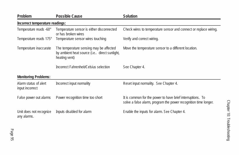
Problem Possible Cause Solution
Incorrect temperature readings:
Temperature reads -60° Temperature sensor is either disconnected Check wires to temperature sensor and connect or replace wiring. or has broken wires
Temperature reads 175° Temperature sensor wires touching Verify and correct wiring.
Temperature inaccurate The temperature sensing may be affected Move the temperature sensor to a different location. by ambient heat source (i.e.. direct sunlight,heating vent)
Incorrect Fahrenheit/Celsius selection See Chapter 4.
Monitoring Problems:
Alarm status of alert Incorrect input normality Reset input normality. See Chapter 4.input incorrect
False power out alarms Power recognition time too short It is common for the power to have brief interruptions. To solve a false alarm, program the power recognition time longer.
Unit does not recognize Inputs disabled for alarm Enable the inputs for alarm. See Chapter 4. any alarms.
Chapter 10: Troubleshooting
Page 95

Sensaphone Express User’s Manual
Page 96

APPENDIX A: CHECKING YOUR SENSAPHONEFOR PROPER OPERATION
We recommend that you test your Sensaphone weekly to be sureit is functioning properly. This will ensure that when a problemarises the Sensaphone will be ready to alert the appropriate per-sonnel.
There are several tests that can be performed:
1) Call the unit and listen to the Status Report. This will testthe unit’s ability to answer the phone and speak a message. Itwill also verify that all of the inputs are reading properly, thealarm conditions are OK, the electricity is on and the micro-phone is functioning.
2) Create an alarm on each input and allow the unit to contactall programmed telephone numbers. This will ensure that theSensaphone is programmed properly. It will also prepare person-nel to respond appropriately when they receive a call from theSensaphone.
3) Test the battery by unplugging the AC adapter and makingsure that the Sensaphone continues to function. Press WHATIS, then STATUS on the keypad, and listen to the status report.Make sure the report states that “the electricity is off.” Check the"Battery OK" LED and make sure it is on steady. Keep the ACadapter unplugged so that a Power Failure alarm occurs. Allowthe unit to dial all programmed telephone numbers while run-ning on battery backup. Plug in the AC adapter after the unithas finished dialing all of the telephone numbers.
Appendix A: Checking for Proper Operation
Page 97

Sensaphone Express User’s Manual
Page 98

APPENDIX B: ACCESSORIES
The sensors listed are the most commonly used input devices.However, there is a virtually unlimited variety of sensor/switchinput devices available at commercial or industrial electrical sup-ply houses. They can provide a device to monitor virtually anycondition that might be required for your business, industrial orresidential needs. Contact PHONETICS, INC. at 610-558-2700for more information.
MODEL SENSOR/NUMBER SWITCH FGD-0006 Magnetic Reed SwitchFGD-0007 Passive Infrared DetectorFGD-0010 50' two-conductor #22AWG shielded Accessory CableFGD-0013 Spot Water DetectorFGD-0022 Temp AlertFGD-0023 ISOTEL Surge ProtectorFGD-0027 HumidistatFGD-0049 Smoke Detector w/Built-in RelayFGD-0054 Power-Out Alert™FGD-0056 Zone Water Detector w/Water RopeFGD-0063 10' additional Water Rope for FGD-0056FGD-0100 2.8K Remote Temperature SensorFGD-0101 2.8K Weatherproof Temperature ProbeFGD-0102 10K Weatherproof Temperature ProbeFGD-0103 10K Indoor Zone Temperature SensorFGD-0104 10K Outdoor Air Temperature SensorFGD-0105 10K Immersion Temperature SensorFGD-0200 Phonecell SX3e Cellular Phone
Appendix B: Accessories
Page 99

Sensaphone Express User’s Manual
Page 100

DEGREES (Celsius)
-37-35-32-29-26-23-21-18-15-12-9-6-4-1247
1013161821242730323538414447495255586063666971747780838688919497
DEGREES (Fahrenheit)
-35-30-25-20-15-10-505
101520253035404550556065707580859095
100105110115120125130135140145150155160165170175180185190195200205
RESISTANCE (Ohms)
203.60K173.60K148.30K127.10K109.20K94.07K81.23K70.32K61.02K53.07K46.27K40.42K35.39K31.06K27.31K24.06K21.24K18.79K16.65K14.78K13.15K11.72K10.46K9.35K8.38K7.52K6.75K6.08K5.48K4.95K4.47K4.05K3.67K3.33K3.31K2.76K2.52K2.30K2.10K1.92K1.76K1.61K1.48K1.36K1.25K1.16K1.07K0.98K0.91K
Appendix C: Look-Up Table
Page 101
APPENDIX C: 10K THERMISTOR LOOK-UP TABLE

Sensaphone Express User’s Manual
Page 102

APPENDIX D: RETURNING UNITS FOR REPAIR
In the event that Express does not function properly and youcannot reprogram it, we suggest that you do the following:
1) Carefully write down your observations of Express’s malfunc-tioning.
2) Call Phonetics Technical Service at 610-558-2700 if anyinstructions are not clear or if you have any questions.
If the unit must be sent to us for servicing, do the following:
1) Turn the power switch off, unplug the AC power supplyfrom the wall outlet, and disconnect all sensors from the alertinputs.
2) Carefully pack unit into its original container or a sturdyshipping box. Be certain to use sufficient cushioning material toavoid damage in transit.
3) Address package to:
SERVICE DEPARTMENTPHONETICS, INC.
901 TRYENS ROADASTON, PA 19014
4) Ship prepaid and insured via UPS or US Mail to ensure atraceable shipment with recourse for damage or replacement.
5) To avoid processing delays, be sure to include the following:
a) Your name, address, and phone numberb) Model and Serial numbersc) A letter explaining Express’s problem
Appendix D: Returing Units for Repair
Page 103