sensaphone model 4100 - absolute automation usa
TRANSCRIPT

Sensaphone® Model 4100User’s Manual
Version 5.1
Phonetics, Inc.

Every effort has been made to ensure that the information in this document iscomplete, accurate and up-to-date. Phonetics, Inc. assumes no responsibility forthe results of errors beyond its control. Phonetics, Inc. also cannot guarantee thatchanges in equipment made by other manufacturers will not affect the applicabilityof the information in this manual.
Copyright 1998 by Phonetics, Inc.
Fifth Edition, version 5.1.September, 2000
Written and produced by Phonetics, Inc.
Phonetics, Inc.
Sensaphone is a registered trademark of Phonetics, Inc.
Touch-Tone is a registered trademark of AT&T
i
ContentsVersion 5.1
CHAPTER 1: INTRODUCTION .....................................................3ABOUT THIS MANUAL ................................................................................... 3
CHAPTER 2: INSTALLATION .........................................................5OPERATING ENVIRONMENT ......................................................................... 5MOUNTING .................................................................................................... 5POWER SURGE PROTECTION ........................................................................ 6POWER SUPPLY AND BACKUP BATTERY........................................................ 6BATTERY CONNECTION ................................................................................. 6TURNING THE MODEL 4100 ON ................................................................... 7STRAIN RELIEF ................................................................................................. 7PHONE LINE INSTALLATION .......................................................................... 7TEMPERATURE SENSORS ................................................................................ 8THE MICROPHONE ........................................................................................ 9ALERT INPUTS ................................................................................................. 9MULTIPLE SENSORS ...................................................................................... 10AUXILIARY TEMPERATURE / ALERT INPUT 4 ................................................ 11OUTDOOR WIRING ..................................................................................... 12DISCONNECTING THE MODEL 4100 (FOR SEASONAL USE OR STORAGE) .... 12FCC REQUIREMENTS .................................................................................... 13CANADIAN DEPARTMENT OF COMMUNICATIONS STATEMENT ............... 14
CHAPTER 3: COMMUNICATIONS PROGRAMMING .................15DIAL-OUT TELEPHONE NUMBERS ............................................................... 15TONE OR PULSE DIALING ............................................................................ 17SPECIAL DIALING ......................................................................................... 17RINGS UNTIL ANSWER & TAD COMPATIBILITY ........................................... 18LISTEN-IN TIME ............................................................................................. 19THE SECURITY CODE ................................................................................... 20THE UNIT ID NUMBER ................................................................................. 21LOCAL VOICE MUTE ..................................................................................... 22TIME .............................................................................................................. 22PRE-PROGRAMMED COMMUNICATIONS FEATURES .................................. 23
CHAPTER 4: ALARM PROGRAMMING .......................................25ENABLE / DISABLE INPUTS ........................................................................... 25CONFIGURE INPUT NORMALITY ................................................................ 26TEMPERATURE LIMITS .................................................................................. 26ENABLE / DISABLE TEMPERATURE INPUTS................................................... 27
ii
AC POWER MONITORING ENABLE / DISABLE ............................................. 28AC POWER FAILURE RECOGNITION TIME ................................................... 29HIGH SOUND ALARM ENABLE / DISABLE ................................................... 30SOUND ALARM MONITORING SENSITIVITY............................................... 30
CHAPTER 5: CALL-IN COMMANDS.............................................33ALARM ACKNOWLEDGMENT ...................................................................... 33STATUS REPORT ............................................................................................ 34
CHAPTER 6: THE OUTPUT ...........................................................35WIRING THE OUTPUT CONTROLLER .......................................................... 35WIRING AN OUTPUT DEVICE TO THE OUTPUT CONTROLLER ................. 35
CHAPTER 7: PROGRAMMING SUMMARY ..................................37MONITORING FUNCTIONS ......................................................................... 37COMMUNICATIONS FUNCTIONS ............................................................... 38
CHAPTER 8: OPERATION ............................................................39PART ONE: THE ALARM DIALOUT SEQUENCE ........................................... 39ALARM RECOGNITION: ............................................................................... 39DIALOUT: ...................................................................................................... 39ACKNOWLEDGMENT: .................................................................................. 40PART TWO: SAMPLE PROGRAMMING STRATEGY ...................................... 41COMMUNICATIONS PROGRAMMING ........................................................ 41MONITORING PROGRAMMING .................................................................. 41EXAMPLES ..................................................................................................... 42EXAMPLE 1: ................................................................................................... 42EXAMPLE 2: ................................................................................................... 43EXAMPLE 3: ................................................................................................... 43EXAMPLE 4: ................................................................................................... 44EXAMPLE 5: ................................................................................................... 45EXAMPLE 6: ................................................................................................... 45EXAMPLE 7: ................................................................................................... 46
APPENDIX A: CHECKING FOR PROPER OPERATION .................47
APPENDIX B: TROUBLESHOOTING ............................................49
APPENDIX C: ACCESSORIES ........................................................53
APPENDIX D: ERROR MESSAGES.................................................55
APPENDIX E: APPLICATIONS.......................................................57
APPENDIX F: RETURNING UNIT FOR REPAIR ............................59
WARRANTY..................................................................................61
Chapter 1: Introduction
3
CHAPTER 1
INTRODUCTION
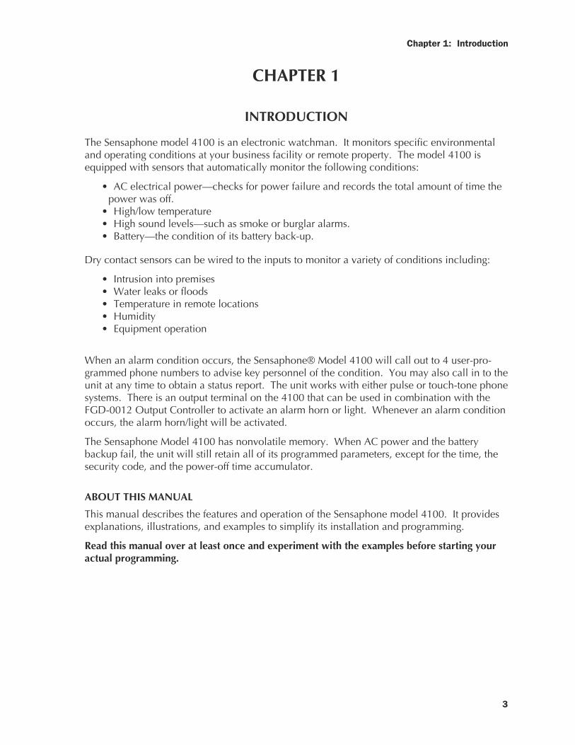
The Sensaphone model 4100 is an electronic watchman. It monitors specific environmentaland operating conditions at your business facility or remote property. The model 4100 isequipped with sensors that automatically monitor the following conditions:
• AC electrical power—checks for power failure and records the total amount of time thepower was off.
• High/low temperature• High sound levels—such as smoke or burglar alarms.• Battery—the condition of its battery back-up.
Dry contact sensors can be wired to the inputs to monitor a variety of conditions including:
• Intrusion into premises• Water leaks or floods• Temperature in remote locations• Humidity• Equipment operation
When an alarm condition occurs, the Sensaphone® Model 4100 will call out to 4 user-pro-grammed phone numbers to advise key personnel of the condition. You may also call in to theunit at any time to obtain a status report. The unit works with either pulse or touch-tone phonesystems. There is an output terminal on the 4100 that can be used in combination with theFGD-0012 Output Controller to activate an alarm horn or light. Whenever an alarm conditionoccurs, the alarm horn/light will be activated.
The Sensaphone Model 4100 has nonvolatile memory. When AC power and the batterybackup fail, the unit will still retain all of its programmed parameters, except for the time, thesecurity code, and the power-off time accumulator.
ABOUT THIS MANUAL
This manual describes the features and operation of the Sensaphone model 4100. It providesexplanations, illustrations, and examples to simplify its installation and programming.
Read this manual over at least once and experiment with the examples before starting youractual programming.

Sensaphone Model 4100 Instruction Manual
4
Chapter 2: Installation
5
CHAPTER 2
INSTALLATION
This chapter provides information on how to install the Sensaphone® 4100. Pleaseread the entire chapter before starting installation.
Within the packaging will be a Warranty Registration Card. Please take the time to fillthis out and mail. The One Year Limited Warranty is explained in the back of thismanual.
CAUTION: The Model 4100 is a sensitive electronic device. Do not install the Model4100 near strong electrostatic, electromagnetic or radioactive fields.
OPERATING ENVIRONMENT
The Model 4100 should be installed and operated in a safe environment. Do not placethe unit where it can be exposed to fumes or corrosive vapors. The vapors may dam-age the unit, thus voiding the warranty. The temperature range that the 4100 canoperate in is 32° F to 120° F.
MOUNTING
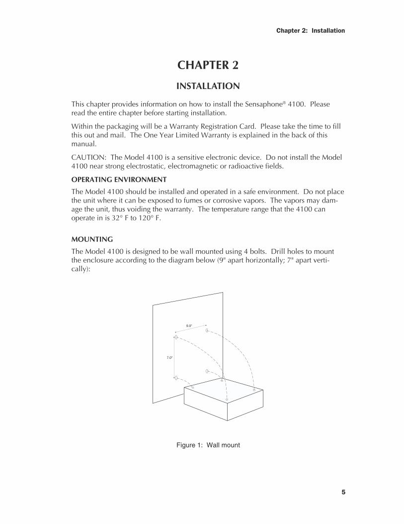
The Model 4100 is designed to be wall mounted using 4 bolts. Drill holes to mountthe enclosure according to the diagram below (9" apart horizontally; 7" apart verti-cally):
9.0"
7.0"
Figure 1: Wall mount
6
Sensaphone® Model 4100 Instruction Manual
POWER SURGE PROTECTION
The Sensaphone® 4100 can be damaged by power surges and lightning through thetelephone line and the 110 VAC power supply. Although the Model 4100 has built-insurge protection, we recommend that additional protection be obtained for the unitand for any electronic equipment that is attached to your power supply and telephonelines. Power surge protection is especially important if you live in a lightning-pronearea. The ISOTEL Surge Protector Model IB-4 is available through Phonetics. SeeAppendix B.
POWER SUPPLY AND BACKUP BATTERY
The 4100 is provided with an AC power transformer. After mounting the unit, plug thetransformer into any standard 110 VAC outlet. The unit will say "Hello" and state anypresent alarms.
The Model 4100 is equipped with a replaceable rechargeable 2.2 Amp-hour gel-cellelectrolyte battery. The battery is recharged whenever the AC transformer is pluggedinto an outlet and the battery jumper is installed on terminals 15 and 16 (see below).Complete recharge will take approximately 48 hours. During that interval, a statusreport may give the "Battery Condition Low" alarm message.
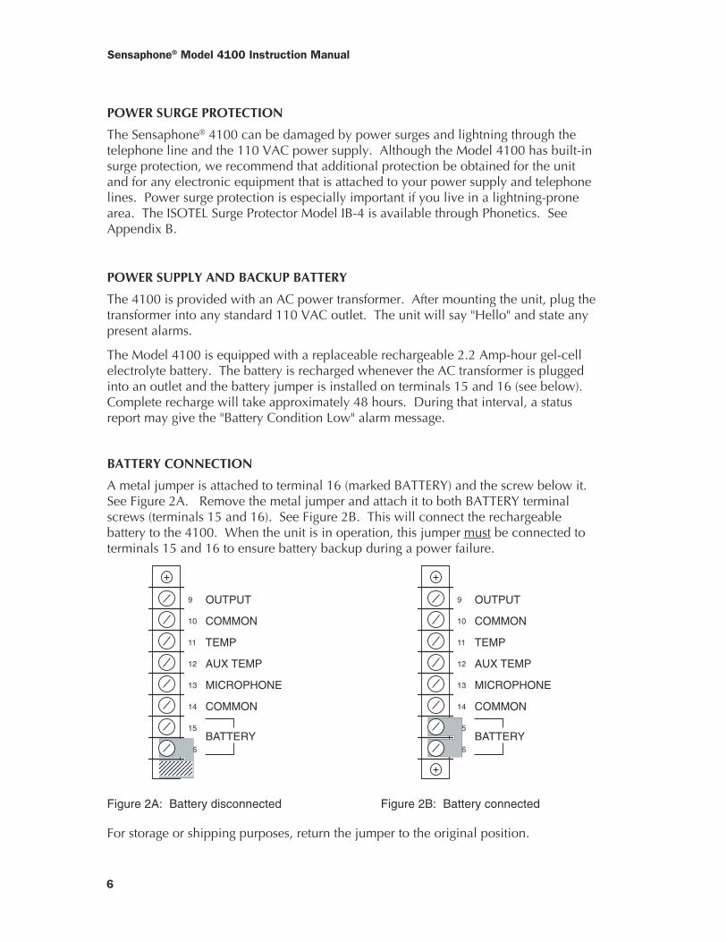
BATTERY CONNECTION
A metal jumper is attached to terminal 16 (marked BATTERY) and the screw below it.See Figure 2A. Remove the metal jumper and attach it to both BATTERY terminalscrews (terminals 15 and 16). See Figure 2B. This will connect the rechargeablebattery to the 4100. When the unit is in operation, this jumper must be connected toterminals 15 and 16 to ensure battery backup during a power failure.
9
10
11
12
13
14
15
16
OUTPUT
COMMON
TEMP
AUX TEMP
MICROPHONE
COMMON
BATTERY
9
10
11
12
13
14
15
16
OUTPUT
COMMON
TEMP
AUX TEMP
MICROPHONE
COMMON
BATTERY
Figure 2A: Battery disconnected Figure 2B: Battery connected
For storage or shipping purposes, return the jumper to the original position.
12345678901234567890123456789012345678901234567890
Chapter 2: Installation
7
TURNING THE MODEL 4100 ON
The ON and OFF keys on the Model 4100 keypad are used to activate and deactivatethe unit. To turn the unit ON, press the ON key. The system ON light will begin toglow. The unit will say “Hello,” or beep if it is already on.
When the unit is ON, it is able to receive incoming calls and automatically dial out inthe event of an alarm on one of the monitored conditions. The red light will glow aslong as the unit is on.
When you press OFF, the 4100 will say “Have a good day,” and the system ON lightwill stop glowing. All functions are disabled except the battery backup. The batterieswill still discharge if the AC transformer is unplugged from the 110 VAC outlet.
It is not recommended that the unit be turned OFF unless absolutely necessary. (See”Disconnecting the Model 4100” later in this chapter.) Full power is still consumed bythe unit even though it cannot be programmed or interrogated. Also, the unit cannotdial out with an alarm.
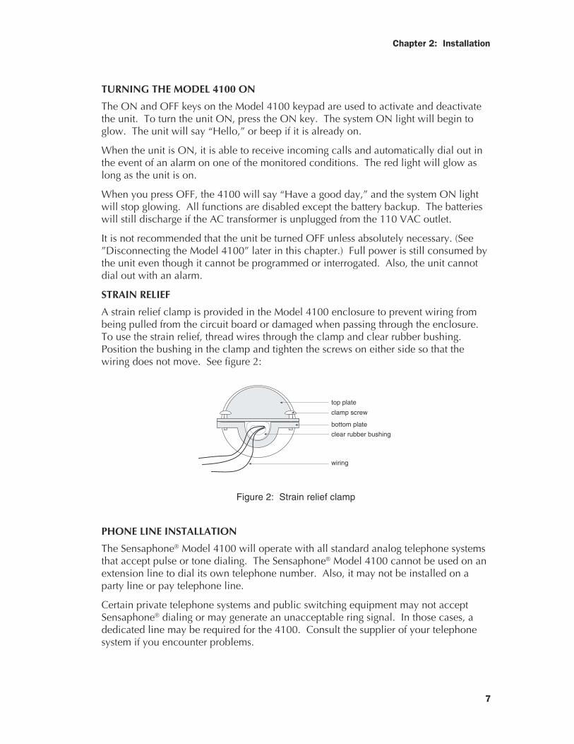
STRAIN RELIEF
A strain relief clamp is provided in the Model 4100 enclosure to prevent wiring frombeing pulled from the circuit board or damaged when passing through the enclosure.To use the strain relief, thread wires through the clamp and clear rubber bushing.Position the bushing in the clamp and tighten the screws on either side so that thewiring does not move. See figure 2:
top plate
clamp screw
bottom plate
clear rubber bushing
wiring
Figure 2: Strain relief clamp
PHONE LINE INSTALLATION
The Sensaphone® Model 4100 will operate with all standard analog telephone systemsthat accept pulse or tone dialing. The Sensaphone® Model 4100 cannot be used on anextension line to dial its own telephone number. Also, it may not be installed on aparty line or pay telephone line.
Certain private telephone systems and public switching equipment may not acceptSensaphone® dialing or may generate an unacceptable ring signal. In those cases, adedicated line may be required for the 4100. Consult the supplier of your telephonesystem if you encounter problems.
8
Sensaphone® Model 4100 Instruction Manual
If you do not have a modular telephone extension at the Model 4100’s location, youmust contact your local telephone company to have one installed (there may be acharge for this service). If you have four-pin jacks, adapters are available to convertthem to the modular plugs. Contact your local telephone company or electronics partsstore.
CAUTION: Never install telephone wiring during a lightning storm. Never installtelephone jacks in wet locations unless the jack is specifically designed for wet loca-tions. Never touch uninsulated telephone wires or terminals unless the telephone linehas been disconnected at the network interface. Use caution when installing or modi-fying telephone lines.
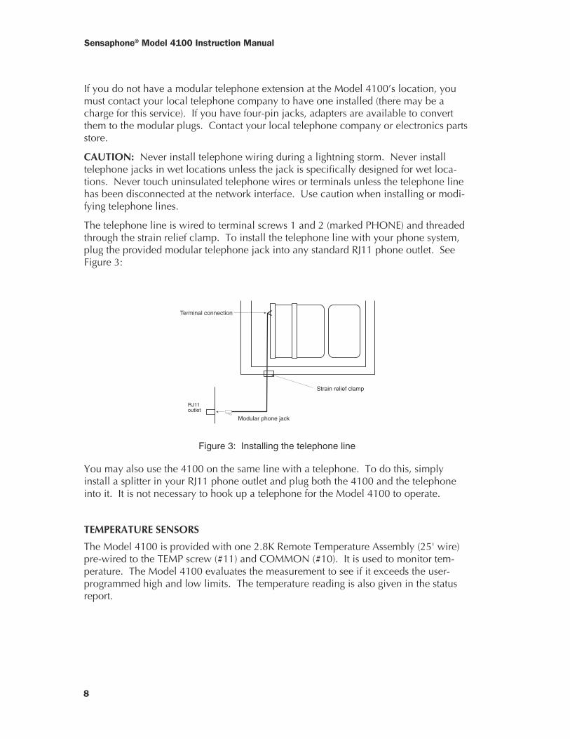
The telephone line is wired to terminal screws 1 and 2 (marked PHONE) and threadedthrough the strain relief clamp. To install the telephone line with your phone system,plug the provided modular telephone jack into any standard RJ11 phone outlet. SeeFigure 3:
Modular phone jack
RJ11 outlet
Strain relief clamp
Terminal connection
Figure 3: Installing the telephone line
You may also use the 4100 on the same line with a telephone. To do this, simplyinstall a splitter in your RJ11 phone outlet and plug both the 4100 and the telephoneinto it. It is not necessary to hook up a telephone for the Model 4100 to operate.
TEMPERATURE SENSORS
The Model 4100 is provided with one 2.8K Remote Temperature Assembly (25' wire)pre-wired to the TEMP screw (#11) and COMMON (#10). It is used to monitor tem-perature. The Model 4100 evaluates the measurement to see if it exceeds the user-programmed high and low limits. The temperature reading is also given in the statusreport.
Chapter 2: Installation
9
THE MICROPHONE
The 4100 is provided with a microphone on a 25' cable to monitor high sound level atyour location. It is pre-wired to screw terminals 13 and 14. The microphone willcontinuously listen for a high sound level that increases approximately 10 decibelsover the normal sound level at a frequency of about 1000 Hertz or more. (NOTE: Thesensitivity of the microphone can be changed. See Chapter 4, “Sound Alarm Monitor-ing Sensitivity.”) If this sound level exists for 8 consecutive seconds or longer (such aswith a smoke alarm or burglar alarm), the Model 4100 will dial out with an alarmmessage.
NOTE: The location of the audible alarm in relation to the microphone is extremelyimportant. Normally, the 4100 and the audible alarm must be in the same room. Themaximum distance can vary considerably depending on the alarm, the acoustics, andthe size of the room.
During an alarm dial out, the microphone allows four 4-second intervals to listen-in tothe Model 4100’s location.
During a call in for a status report, the microphone allows you to listen to on-sitesounds for the user-programmed time interval.
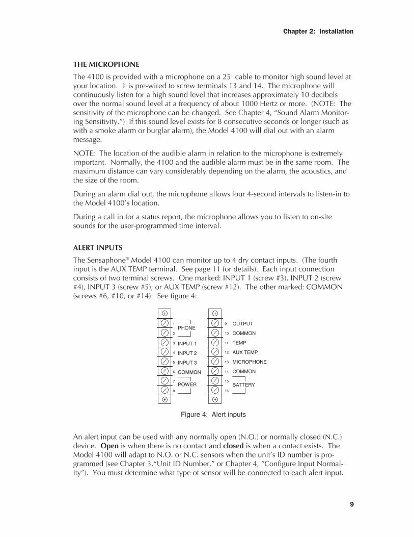
ALERT INPUTS
The Sensaphone® Model 4100 can monitor up to 4 dry contact inputs. (The fourthinput is the AUX TEMP terminal. See page 11 for details). Each input connectionconsists of two terminal screws. One marked: INPUT 1 (screw #3), INPUT 2 (screw#4), INPUT 3 (screw #5), or AUX TEMP (screw #12). The other marked: COMMON(screws #6, #10, or #14). See figure 4:
1
2
3
4
5
6
7
8
PHONE
INPUT 1
INPUT 2
INPUT 3
COMMON
POWER
9
10
11
12
13
14
15
16
OUTPUT
COMMON
TEMP
AUX TEMP
MICROPHONE
COMMON
BATTERY
Figure 4: Alert inputs
An alert input can be used with any normally open (N.O.) or normally closed (N.C.)device. Open is when there is no contact and closed is when a contact exists. TheModel 4100 will adapt to N.O. or N.C. sensors when the unit’s ID number is pro-grammed (see Chapter 3,“Unit ID Number,” or Chapter 4, “Configure Input Normal-ity”). You must determine what type of sensor will be connected to each alert input.
10
Sensaphone® Model 4100 Instruction Manual
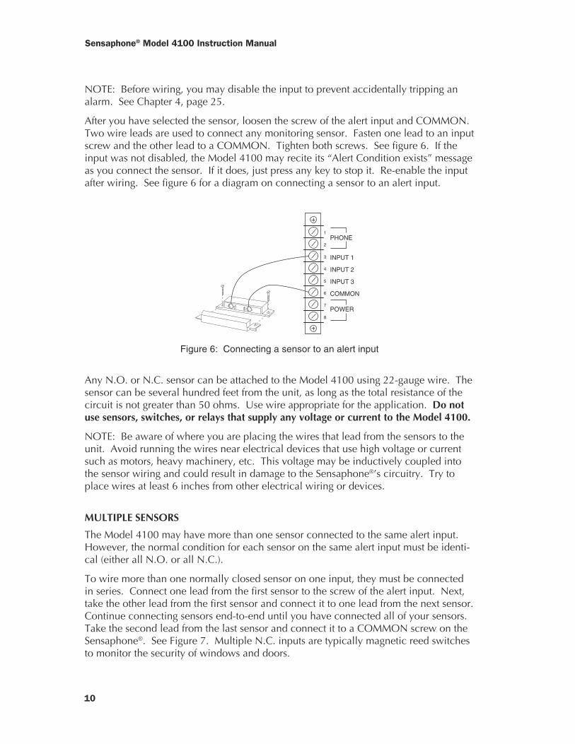
NOTE: Before wiring, you may disable the input to prevent accidentally tripping analarm. See Chapter 4, page 25.
After you have selected the sensor, loosen the screw of the alert input and COMMON.Two wire leads are used to connect any monitoring sensor. Fasten one lead to an inputscrew and the other lead to a COMMON. Tighten both screws. See figure 6. If theinput was not disabled, the Model 4100 may recite its “Alert Condition exists” messageas you connect the sensor. If it does, just press any key to stop it. Re-enable the inputafter wiring. See figure 6 for a diagram on connecting a sensor to an alert input.
1
2
3
4
5
6
7
8
PHONE
INPUT 1
INPUT 2
INPUT 3
COMMON
POWER
Figure 6: Connecting a sensor to an alert input
Any N.O. or N.C. sensor can be attached to the Model 4100 using 22-gauge wire. Thesensor can be several hundred feet from the unit, as long as the total resistance of thecircuit is not greater than 50 ohms. Use wire appropriate for the application. Do notuse sensors, switches, or relays that supply any voltage or current to the Model 4100.
NOTE: Be aware of where you are placing the wires that lead from the sensors to theunit. Avoid running the wires near electrical devices that use high voltage or currentsuch as motors, heavy machinery, etc. This voltage may be inductively coupled intothe sensor wiring and could result in damage to the Sensaphone®’s circuitry. Try toplace wires at least 6 inches from other electrical wiring or devices.
MULTIPLE SENSORS
The Model 4100 may have more than one sensor connected to the same alert input.However, the normal condition for each sensor on the same alert input must be identi-cal (either all N.O. or all N.C.).
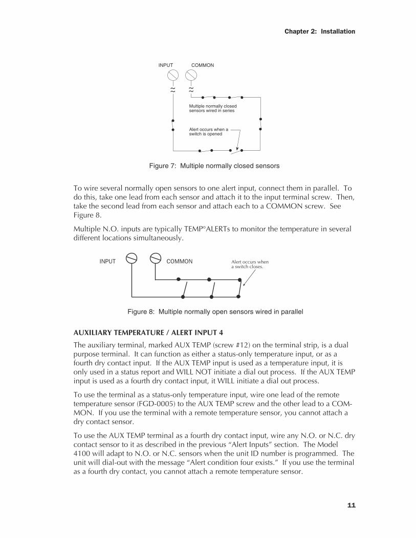
To wire more than one normally closed sensor on one input, they must be connectedin series. Connect one lead from the first sensor to the screw of the alert input. Next,take the other lead from the first sensor and connect it to one lead from the next sensor.Continue connecting sensors end-to-end until you have connected all of your sensors.Take the second lead from the last sensor and connect it to a COMMON screw on theSensaphone®. See Figure 7. Multiple N.C. inputs are typically magnetic reed switchesto monitor the security of windows and doors.
Chapter 2: Installation
11
INPUT COMMON
~~~~Multiple normally closed sensors wired in series
Alert occurs when a switch is opened
Figure 7: Multiple normally closed sensors
To wire several normally open sensors to one alert input, connect them in parallel. Todo this, take one lead from each sensor and attach it to the input terminal screw. Then,take the second lead from each sensor and attach each to a COMMON screw. SeeFigure 8.
Multiple N.O. inputs are typically TEMP°ALERTs to monitor the temperature in severaldifferent locations simultaneously.
INPUT COMMON Alert occurs whena switch closes.
Figure 8: Multiple normally open sensors wired in parallel
AUXILIARY TEMPERATURE / ALERT INPUT 4
The auxiliary terminal, marked AUX TEMP (screw #12) on the terminal strip, is a dualpurpose terminal. It can function as either a status-only temperature input, or as afourth dry contact input. If the AUX TEMP input is used as a temperature input, it isonly used in a status report and WILL NOT initiate a dial out process. If the AUX TEMPinput is used as a fourth dry contact input, it WILL initiate a dial out process.
To use the terminal as a status-only temperature input, wire one lead of the remotetemperature sensor (FGD-0005) to the AUX TEMP screw and the other lead to a COM-MON. If you use the terminal with a remote temperature sensor, you cannot attach adry contact sensor.
To use the AUX TEMP terminal as a fourth dry contact input, wire any N.O. or N.C. drycontact sensor to it as described in the previous “Alert Inputs” section. The Model4100 will adapt to N.O. or N.C. sensors when the unit ID number is programmed. Theunit will dial-out with the message “Alert condition four exists.” If you use the terminalas a fourth dry contact, you cannot attach a remote temperature sensor.
12
Sensaphone® Model 4100 Instruction Manual
OUTDOOR WIRING
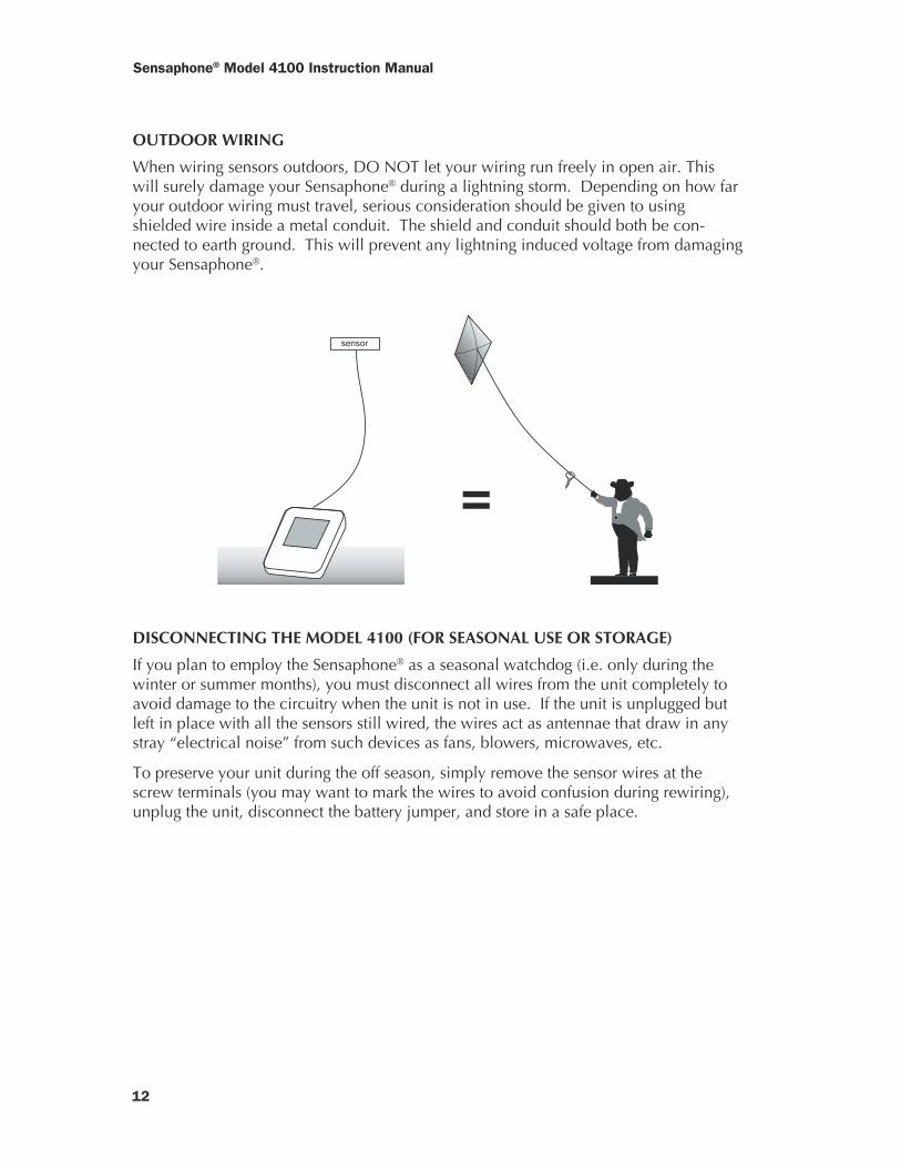
When wiring sensors outdoors, DO NOT let your wiring run freely in open air. Thiswill surely damage your Sensaphone® during a lightning storm. Depending on how faryour outdoor wiring must travel, serious consideration should be given to usingshielded wire inside a metal conduit. The shield and conduit should both be con-nected to earth ground. This will prevent any lightning induced voltage from damagingyour Sensaphone®.
sensor
DISCONNECTING THE MODEL 4100 (FOR SEASONAL USE OR STORAGE)
If you plan to employ the Sensaphone® as a seasonal watchdog (i.e. only during thewinter or summer months), you must disconnect all wires from the unit completely toavoid damage to the circuitry when the unit is not in use. If the unit is unplugged butleft in place with all the sensors still wired, the wires act as antennae that draw in anystray “electrical noise” from such devices as fans, blowers, microwaves, etc.
To preserve your unit during the off season, simply remove the sensor wires at thescrew terminals (you may want to mark the wires to avoid confusion during rewiring),unplug the unit, disconnect the battery jumper, and store in a safe place.
=
Chapter 2: Installation
13
FCC REQUIREMENTS
PART 68 - The Sensaphone® Model 4100 complies with Part 68 of the FCC rules. Onthe inside cover of the unit enclosure there is a label that contains, among other infor-mation, the FCC Registration Number and the Ringer Equivalence Number (REN) forthis equipment. You must, upon request, provide this information to your local tele-phone company.
The REN is useful to determine the quantity of devices that you may connect to yourtelephone line and still have all of those devices ring when your telephone number iscalled. In most, but not all areas, the sum of the REN’s of all devices connected to oneline should not exceed five (5.0). To be certain of the number of devices that you mayconnect to your line, you may want to contact your local telephone company todetermine the maximum REN for your calling area.
This equipment may not be used on coin service provided by the telephone company.Connection to party lines is subject to state tariffs.
Should the Model 4100 cause harm to the telephone network, the telephone companymay discontinue your service temporarily. If possible, they will notify you in advance.But if advanced notice is not practical, the telephone company may temporarily dis-continue service without notice and you will be notified as soon as possible. You willbe informed of your right to file a complaint with the FCC. The telephone companymay make changes in its facilities, equipment, operations, or procedures where suchaction is reasonably required in the operation of its business and is not inconsistentwith the rules and regulations of the FCC that could affect the proper functioning ofyour equipment.
The telephone company may ask thatyou disconnect this equipment from the network until the problem has been correctedor until you are sure that the equipment is not malfunctioning.
PART 15 - This equipment has been tested and found to comply with the limits for aClass B digital device, pursuant to Part 15 of the FCC Rules. These limits are designedto provide reasonable protection against harmful interference when the equipment isoperated in a commercial environment. This equipment generates, uses and canradiate radio frequency energy and if not installed and used in accordance with theinstruction manual, may cause harmful interference to radio communications. Opera-tion of this equipment in a residential area is likely to cause harmful interference inwhich case the user will be required to correct the interference at his own expense.
14
Sensaphone® Model 4100 Instruction Manual
CANADIAN DEPARTMENT OF COMMUNICATIONS STATEMENT
Notice: The Canadian Department of Communications label identifies certifiedequipment. This certification means that the equipment meets certain telecom-munications network protective operational and safety requirements. The Depart-ment does not guarantee the equipment will operate to the user’s satisfaction.
Before installing this equipment, users should ensure that it is permissible to beconnected to the facilities of the local telecommunications company. The equip-ment must also be installed using an acceptable method of connection. In somecases, the company’s inside wiring associated with a single line individual servicemay be extended by means of a certified connector assembly (telephone exten-sion cord). The customer should be aware that compliance with the aboveconditions may not prevent degradation of service in some situations.
Repairs to certified equipment should be made by an authorized Canadian main-tenance facility designated by the supplier. Any repairs or alterations made by theuser to this equipment, or equipment malfunctions, may give the telecommunica-tions company cause to request the user to disconnect the equipment.
Users should ensure for their own protection that the electrical ground connec-tions of the power utility, telephone lines and internal metallic water pipe system,if present, are connected together. This precaution may be particularly importantin rural areas.
CAUTION: Users should not attempt to make such connections themselves, butshould contact the appropriate electric inspection authority, or electrician, asappropriate.
The Load Number (LN) assigned to each terminal device denotes the percentageof the total load to be connected to a telephone loop which is used by the deviceto prevent overloading. The termination on a loop may consist of any combina-tion of devices subject only to the requirement that the total of the Load Numberof all the devices does not exceed 100.
The Load Number for the Sensaphone® 4100 is 72.
15
Chapter 3: Communications Programming
CHAPTER 3
COMMUNICATIONS PROGRAMMING
This chapter explains the keyboard functions for the communications operations for theModel 4100. This includes programming, interrogation, and/or resetting of:
• Dial-out telephone numbers• Special dialing• Tone or pulse dialing• Rings until answer & Telephone Answering Device compatibility• Listen-in time• Security code• Unit ID number• Local voice mute• Pre-programmed communications features:• Call delay time• Intercall delay time• Voice repetitions• Maximum number of calls
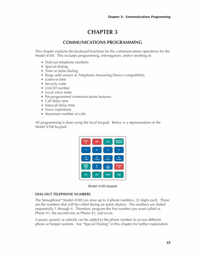
All programming is done using the local keypad. Below is a representation of theModel 4100 keypad.
WHATIS SET KEY SENSOR
ON/OFF
4321
5L TEMP
6H TEMP
7ELECT.
8SOUND
PAUSETONEMUTE
AM
9I.D.
0RINGS
TAD
ENTERPM
TIMETEMPOFFON
Model 4100 keypad
DIAL-OUT TELEPHONE NUMBERS
The Sensaphone® Model 4100 can store up to 4 phone numbers, 32 digits each. Theseare the numbers that will be called during an alarm dialout. The numbers are dialedsequentially 1 through 4. Therefore, program the first number you want called asPhone #1, the second one as Phone #2, and so on.
A pause, pound, or asterisk can be added to the phone number to access differentphone or beeper systems. See “Special Dialing” in this chapter for further explanation.
Sensaphone® Model 4100 Instruction Manual
16
IMPORTANT: It is recommended that you do not program the Sensaphone® Model4100 to dial out to telephone numbers that will be answered by an answering machine.Such alarms will not be acknowledged and the unit will continue to dial indefinitely.
Instruct key people at each telephone number about the Model 4100 and about whatactions they should take if called with an alarm. If necessary, instruct switchboardoperators to handle alarm and acknowledgment calls. Do not have the alarm callanswered by a person who is unable to acknowledge the alarm or to take prompt,effective action to deal with the situation. If appropriate, conduct periodic drills tofamiliarize personnel with the operation of the unit.
In some areas, municipal services (i.e. police, fire, medical) will not respond to auto-matic voice messages. Check with your local municipal services.
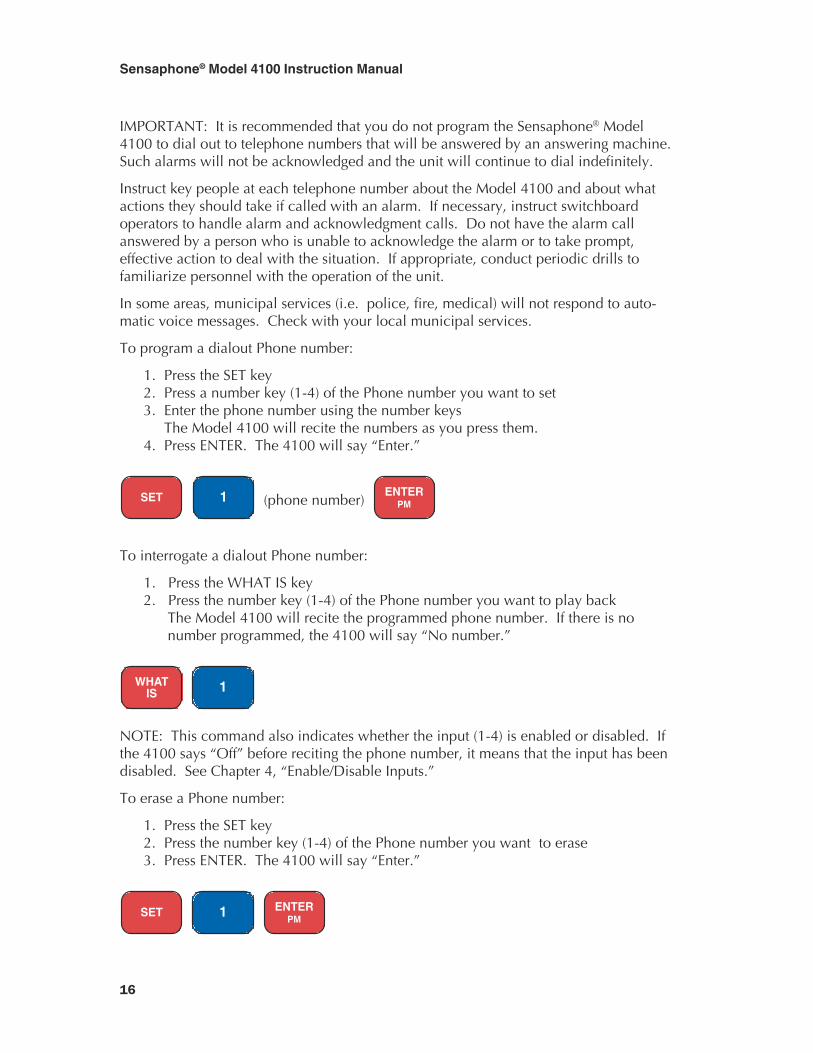
To program a dialout Phone number:
1. Press the SET key2. Press a number key (1-4) of the Phone number you want to set3. Enter the phone number using the number keys The Model 4100 will recite the numbers as you press them.4. Press ENTER. The 4100 will say “Enter.”
SET 1 (phone number) ENTER
PM
To interrogate a dialout Phone number:
1. Press the WHAT IS key2. Press the number key (1-4) of the Phone number you want to play back
The Model 4100 will recite the programmed phone number. If there is nonumber programmed, the 4100 will say “No number.”
WHATIS 1
NOTE: This command also indicates whether the input (1-4) is enabled or disabled. Ifthe 4100 says “Off” before reciting the phone number, it means that the input has beendisabled. See Chapter 4, “Enable/Disable Inputs.”
To erase a Phone number:
1. Press the SET key2. Press the number key (1-4) of the Phone number you want to erase3. Press ENTER. The 4100 will say “Enter.”
SET 1 ENTER
PM
17
Chapter 3: Communications Programming
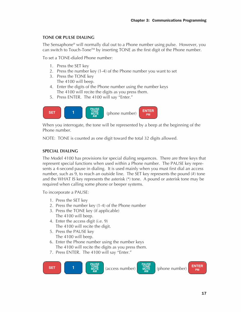
TONE OR PULSE DIALING
The Sensaphone® will normally dial out to a Phone number using pulse. However, youcan switch to Touch-ToneTM by inserting TONE as the first digit of the Phone number.
To set a TONE-dialed Phone number:
1. Press the SET key2. Press the number key (1-4) of the Phone number you want to set3. Press the TONE key
The 4100 will beep.4. Enter the digits of the Phone number using the number keys
The 4100 will recite the digits as you press them.5. Press ENTER. The 4100 will say “Enter.”
SET 1 PAUSETONEMUTE
AM (phone number)
ENTERPM
When you interrogate, the tone will be represented by a beep at the beginning of thePhone number.
NOTE: TONE is counted as one digit toward the total 32 digits allowed.
SPECIAL DIALING
The Model 4100 has provisions for special dialing sequences. There are three keys thatrepresent special functions when used within a Phone number. The PAUSE key repre-sents a 4-second pause in dialing. It is used mainly when you must first dial an accessnumber, such as 9, to reach an outside line. The SET key represents the pound (#) toneand the WHAT IS key represents the asterisk (*) tone. A pound or asterisk tone may berequired when calling some phone or beeper systems.
To incorporate a PAUSE:
1. Press the SET key2. Press the number key (1-4) of the Phone number3. Press the TONE key (if applicable) The 4100 will beep.4. Enter the access digit (i.e. 9) The 4100 will recite the digit.5. Press the PAUSE key The 4100 will beep.6. Enter the Phone number using the number keys The 4100 will recite the digits as you press them.7. Press ENTER. The 4100 will say “Enter.”
SET 1 PAUSETONEMUTE
AM (access number)
PAUSETONEMUTE
AM (phone number)
ENTERPM
Sensaphone® Model 4100 Instruction Manual
18
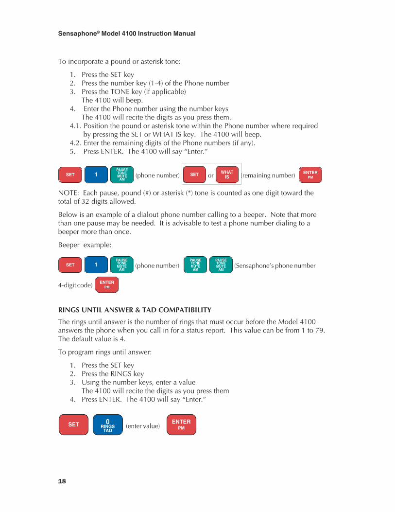
To incorporate a pound or asterisk tone:
1. Press the SET key2. Press the number key (1-4) of the Phone number3. Press the TONE key (if applicable)
The 4100 will beep.4. Enter the Phone number using the number keys
The 4100 will recite the digits as you press them.4.1. Position the pound or asterisk tone within the Phone number where required
by pressing the SET or WHAT IS key. The 4100 will beep.4.2. Enter the remaining digits of the Phone numbers (if any).5. Press ENTER. The 4100 will say “Enter.”
SET 1 PAUSETONEMUTE
AM (phone number) SET or WHAT
IS (remaining number) ENTERPM
NOTE: Each pause, pound (#) or asterisk (*) tone is counted as one digit toward thetotal of 32 digits allowed.
Below is an example of a dialout phone number calling to a beeper. Note that morethan one pause may be needed. It is advisable to test a phone number dialing to abeeper more than once.
Beeper example:
SET 1 PAUSETONEMUTE
AM (phone number)
PAUSETONEMUTE
AM
PAUSETONEMUTE
AM (Sensaphone’s phone number
4-digit code) ENTERPM
RINGS UNTIL ANSWER & TAD COMPATIBILITY
The rings until answer is the number of rings that must occur before the Model 4100answers the phone when you call in for a status report. This value can be from 1 to 79.The default value is 4.
To program rings until answer:
1. Press the SET key2. Press the RINGS key3. Using the number keys, enter a value
The 4100 will recite the digits as you press them4. Press ENTER. The 4100 will say “Enter.”
SET 0RINGS
TAD (enter value)
ENTERPM
19
Chapter 3: Communications Programming
TAD Compatibility stands for Telephone Answering Device Compatibility. This meansthat the Model 4100 can be used on the same telephone line with telephone answeringdevices, such as answering machines and modems. In normal operation (see NOTEbelow), when your phone is called, the answering machine will always answer firstand take a message. The TAD feature provides a method for you to bypass the answer-ing machine and access the 4100 when you call in for a status report. This feature isused in conjunction with RINGS UNTIL ANSWER.
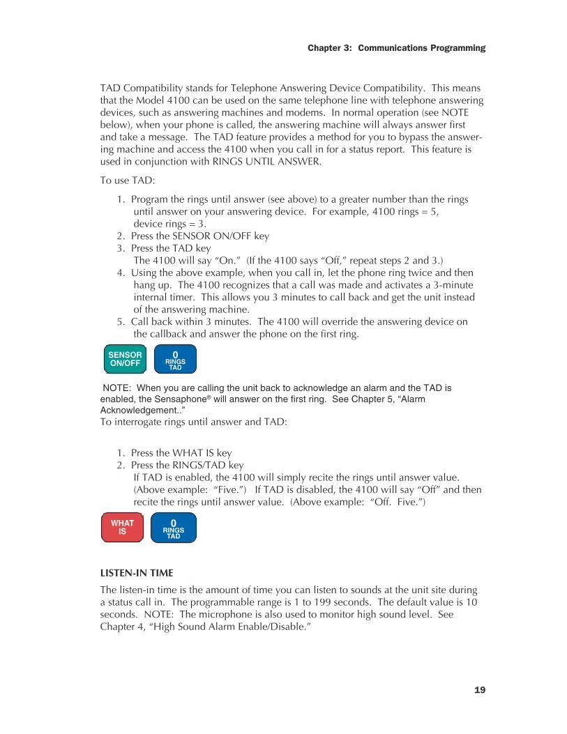
To use TAD:
1. Program the rings until answer (see above) to a greater number than the ringsuntil answer on your answering device. For example, 4100 rings = 5,device rings = 3.
2. Press the SENSOR ON/OFF key3. Press the TAD key
The 4100 will say “On.” (If the 4100 says “Off,” repeat steps 2 and 3.)4. Using the above example, when you call in, let the phone ring twice and then
hang up. The 4100 recognizes that a call was made and activates a 3-minuteinternal timer. This allows you 3 minutes to call back and get the unit insteadof the answering machine.
5. Call back within 3 minutes. The 4100 will override the answering device onthe callback and answer the phone on the first ring.
SENSORON/OFF 0
RINGSTAD
NOTE: When you are calling the unit back to acknowledge an alarm and the TAD isenabled, the Sensaphone® will answer on the first ring. See Chapter 5, “AlarmAcknowledgement..”To interrogate rings until answer and TAD:
1. Press the WHAT IS key2. Press the RINGS/TAD key
If TAD is enabled, the 4100 will simply recite the rings until answer value.(Above example: “Five.”) If TAD is disabled, the 4100 will say “Off” and thenrecite the rings until answer value. (Above example: “Off. Five.”)
WHATIS
0RINGS
TAD
LISTEN-IN TIME
The listen-in time is the amount of time you can listen to sounds at the unit site duringa status call in. The programmable range is 1 to 199 seconds. The default value is 10seconds. NOTE: The microphone is also used to monitor high sound level. SeeChapter 4, “High Sound Alarm Enable/Disable.”
Sensaphone® Model 4100 Instruction Manual
20
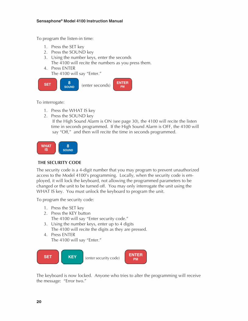
To program the listen-in time:
1. Press the SET key2. Press the SOUND key3. Using the number keys, enter the seconds
The 4100 will recite the numbers as you press them.4. Press ENTER
The 4100 will say “Enter.”
SET 8SOUND (enter seconds)
ENTERPM
To interrogate:
1. Press the WHAT IS key2. Press the SOUND key
If the High Sound Alarm is ON (see page 30), the 4100 will recite the listentime in seconds programmed. If the High Sound Alarm is OFF, the 4100 will say “Off,” and then will recite the time in seconds programmed.
WHATIS
8SOUND
THE SECURITY CODE
The security code is a 4-digit number that you may program to prevent unauthorizedaccess to the Model 4100’s programming. Locally, when the security code is em-ployed, it will lock the keyboard, not allowing the programmed parameters to bechanged or the unit to be turned off. You may only interrogate the unit using theWHAT IS key. You must unlock the keyboard to program the unit.
To program the security code:
1. Press the SET key2. Press the KEY button
The 4100 will say “Enter security code.”3. Using the number keys, enter up to 4 digits
The 4100 will recite the digits as they are pressed.4. Press ENTER
The 4100 will say “Enter.”
SET KEY (enter security code) ENTER
PM
The keyboard is now locked. Anyone who tries to alter the programming will receivethe message: “Error two.”

21
Chapter 3: Communications Programming
NOTE: Unauthorized personnel are prevented from changing any of the Model 4100'sprogramming. However, they are not stopped from using WHAT IS to find out anyinformation. Additional protection may be necessary.
To unlock the keyboard:
1. Press the WHAT IS key2. Press the KEY button
The 4100 will say “Enter security code.”3. Using the number keys, enter the digits of the programmed code
The 4100 will recite the digits as they are pressed.4. Press ENTER
If the correct code is entered, the 4100 will say “OK.” If the wrong code isentered, the 4100 will say “Error two.”
WHATIS KEY (enter security code)
ENTERPM
THE UNIT ID NUMBER
The Model 4100 unit ID number can be up to 32 digits long. It is usually the tele-phone number where the unit is installed. The ID should be programmed AFTER allthe sensors are wired to the unit in their normal state. Programming the ID numberestablishes the normal condition of the alert input in the Model 4100’s memory.
To program the ID number:
1. Press the SET key2. Press the ID# key3. Using the number keys, enter up to 32 digits for the ID number
The 4100 will recite the digits as they are pressed.4. Press ENTER
The 4100 will say “Enter.”
SET 9
I.D. (enter number) ENTER
PM
To interrogate:
1. Press the WHAT IS key2. Press the ID# keyThe 4100 will say “This is telephone number,” then recite the ID number and provide astatus report. (See Chapter 5, “Status Report,” for more information.)
WHATIS
9I.D.
Sensaphone® Model 4100 Instruction Manual
22
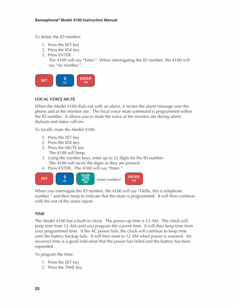
To delete the ID number:
1. Press the SET key2. Press the ID# key3. Press ENTER
The 4100 will say “Enter.” When interrogating the ID number, the 4100 willsay “no number.”
SET 9
I.D. ENTER
PM
LOCAL VOICE MUTE
When the Model 4100 dials out with an alarm, it recites the alarm message over thephone and at the monitor site. The local voice mute command is programmed withinthe ID number. It allows you to mute the voice at the monitor site during alarmdialouts and status call-ins.
To locally mute the Model 4100:
1. Press the SET key2. Press the ID# key3. Press the MUTE key
The 4100 will beep.3. Using the number keys, enter up to 32 digits for the ID number
The 4100 will recite the digits as they are pressed.4. Press ENTER. The 4100 will say “Enter.”
SET 9I.D.
PAUSETONEMUTE
AM (enter number)
ENTERPM
When you interrogate the ID number, the 4100 will say “Hello, this is telephonenumber,” and then beep to indicate that the mute is programmed. It will then continuewith the rest of the status report.
TIME
The Model 4100 has a built-in clock. The power-up time is 12 AM. The clock willkeep time from 12 AM until you program the current time. It will then keep time fromyour programmed time. If the AC power fails, the clock will continue to keep timeuntil the battery backup fails. It will then reset to 12 AM when power is restored. Anincorrect time is a good indication that the power has failed and the battery has beenexpended.
To program the time:
1. Press the SET key2. Press the TIME key
23
Chapter 3: Communications Programming
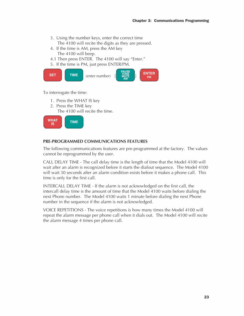
3. Using the number keys, enter the correct timeThe 4100 will recite the digits as they are pressed.
4. If the time is AM, press the AM keyThe 4100 will beep.
4.1 Then press ENTER. The 4100 will say “Enter.”5. If the time is PM, just press ENTER/PM.
SET TIME (enter number) [PAUSETONEMUTE
AM]
ENTERPM
To interrogate the time:
1. Press the WHAT IS key2. Press the TIME key
The 4100 will recite the time.
WHATIS TIME
PRE-PROGRAMMED COMMUNICATIONS FEATURES
The following communications features are pre-programmed at the factory. The valuescannot be reprogrammed by the user.
CALL DELAY TIME - The call delay time is the length of time that the Model 4100 willwait after an alarm is recognized before it starts the dialout sequence. The Model 4100will wait 30 seconds after an alarm condition exists before it makes a phone call. Thistime is only for the first call.
INTERCALL DELAY TIME - If the alarm is not acknowledged on the first call, theintercall delay time is the amount of time that the Model 4100 waits before dialing thenext Phone number. The Model 4100 waits 1 minute before dialing the next Phonenumber in the sequence if the alarm is not acknowledged.
VOICE REPETITIONS - The voice repetitions is how many times the Model 4100 willrepeat the alarm message per phone call when it dials out. The Model 4100 will recitethe alarm message 4 times per phone call.

Sensaphone® Model 4100 Instruction Manual
24
25
Chapter 4: Alarm Programming
CHAPTER 4
ALARM PROGRAMMING
This chapter explains the monitoring capabilities and keyboard commands to programthe monitoring functions of the Model 4100. This includes:
• Enable/disable inputs• Input recognition time• Configure input normality (The ID Number)• Enable/disable temperature input• Temperature limits• AC power monitoring enable/disable• AC power recognition time• High sound monitoring• Disable high sound alarm• Desensitize sound monitoring
ENABLE / DISABLE INPUTS
This function allows you to enable or disable an input (1-3, AUX TEMP) from dialingout during an alarm. An enabled input will respond to an alarm and allow dialout. Adisabled input will not initiate a dialout. This command is useful while you are wiringyour inputs (see pages 9-10), or at any other time you would like the alarms to beignored. The default setting for all inputs is enabled (on).
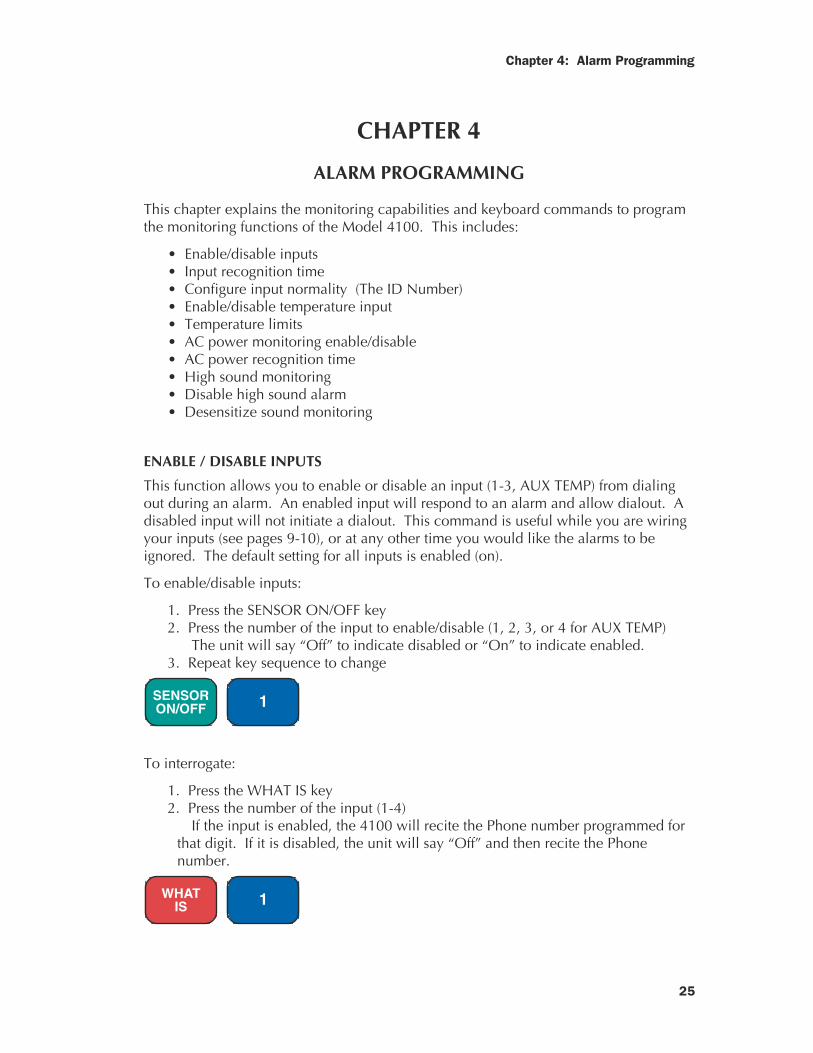
To enable/disable inputs:
1. Press the SENSOR ON/OFF key2. Press the number of the input to enable/disable (1, 2, 3, or 4 for AUX TEMP)
The unit will say “Off” to indicate disabled or “On” to indicate enabled.3. Repeat key sequence to change
SENSORON/OFF 1
To interrogate:
1. Press the WHAT IS key2. Press the number of the input (1-4)
If the input is enabled, the 4100 will recite the Phone number programmed forthat digit. If it is disabled, the unit will say “Off” and then recite the Phonenumber.
WHATIS 1
Sensaphone® Model 4100 Instruction Manual
26
CONFIGURE INPUT NORMALITY
Inputs must be configured as normally open or normally closed. The default for allinputs is open. See Chapter 2, “Alert Inputs,” for further explanation on wiring inputs.It is useful to disable inputs prior to wiring to prevent an alarm dialout. After this isdone, the Model 4100 must initialize the inputs as normal. Do this by programmingthe unit’s ID number. When the ID number is set, the Model 4100 looks at the 4inputs and establishes the present open/closed state as normal. Any change from thatis an alarm. The ID number is also (usually) the unit phone number. This number isrecited during a status report and alarm dialout report.
To set the status of the inputs as normal:
1. Disable the input2. Wire the input3. Program the ID#4. Enable the input.
The inputs are now considered normal. If a normally closed input becomes open, analarm will occur. If a normally open input becomes closed, an alarm will occur.
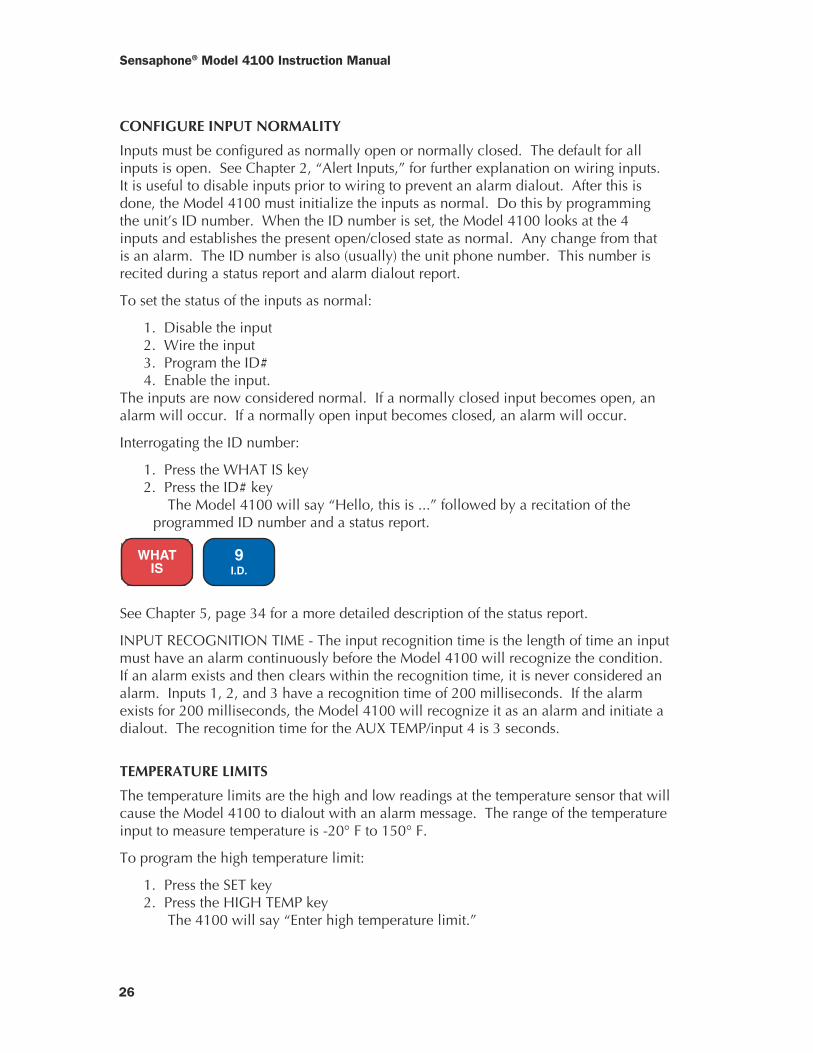
Interrogating the ID number:
1. Press the WHAT IS key2. Press the ID# key
The Model 4100 will say “Hello, this is ...” followed by a recitation of theprogrammed ID number and a status report.
WHATIS
9I.D.
See Chapter 5, page 34 for a more detailed description of the status report.
INPUT RECOGNITION TIME - The input recognition time is the length of time an inputmust have an alarm continuously before the Model 4100 will recognize the condition.If an alarm exists and then clears within the recognition time, it is never considered analarm. Inputs 1, 2, and 3 have a recognition time of 200 milliseconds. If the alarmexists for 200 milliseconds, the Model 4100 will recognize it as an alarm and initiate adialout. The recognition time for the AUX TEMP/input 4 is 3 seconds.
TEMPERATURE LIMITS
The temperature limits are the high and low readings at the temperature sensor that willcause the Model 4100 to dialout with an alarm message. The range of the temperatureinput to measure temperature is -20° F to 150° F.
To program the high temperature limit:
1. Press the SET key2. Press the HIGH TEMP key
The 4100 will say “Enter high temperature limit.”
27
Chapter 4: Alarm Programming
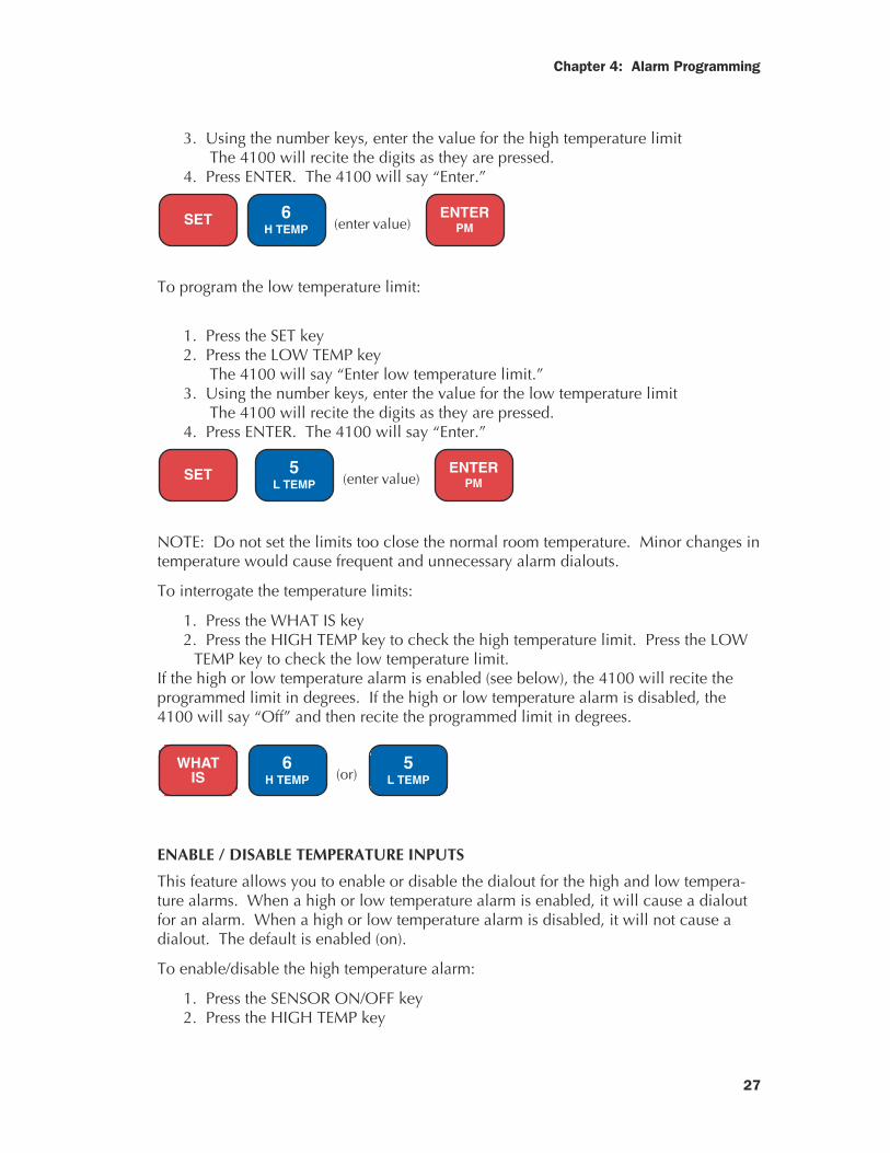
3. Using the number keys, enter the value for the high temperature limitThe 4100 will recite the digits as they are pressed.
4. Press ENTER. The 4100 will say “Enter.”
SET 6
H TEMP (enter value) ENTER
PM
To program the low temperature limit:
1. Press the SET key2. Press the LOW TEMP key
The 4100 will say “Enter low temperature limit.”3. Using the number keys, enter the value for the low temperature limit
The 4100 will recite the digits as they are pressed.4. Press ENTER. The 4100 will say “Enter.”
SET 5
L TEMP (enter value) ENTER
PM
NOTE: Do not set the limits too close the normal room temperature. Minor changes intemperature would cause frequent and unnecessary alarm dialouts.
To interrogate the temperature limits:
1. Press the WHAT IS key2. Press the HIGH TEMP key to check the high temperature limit. Press the LOW
TEMP key to check the low temperature limit.If the high or low temperature alarm is enabled (see below), the 4100 will recite theprogrammed limit in degrees. If the high or low temperature alarm is disabled, the4100 will say “Off” and then recite the programmed limit in degrees.
WHATIS
6H TEMP (or)
5L TEMP
ENABLE / DISABLE TEMPERATURE INPUTS
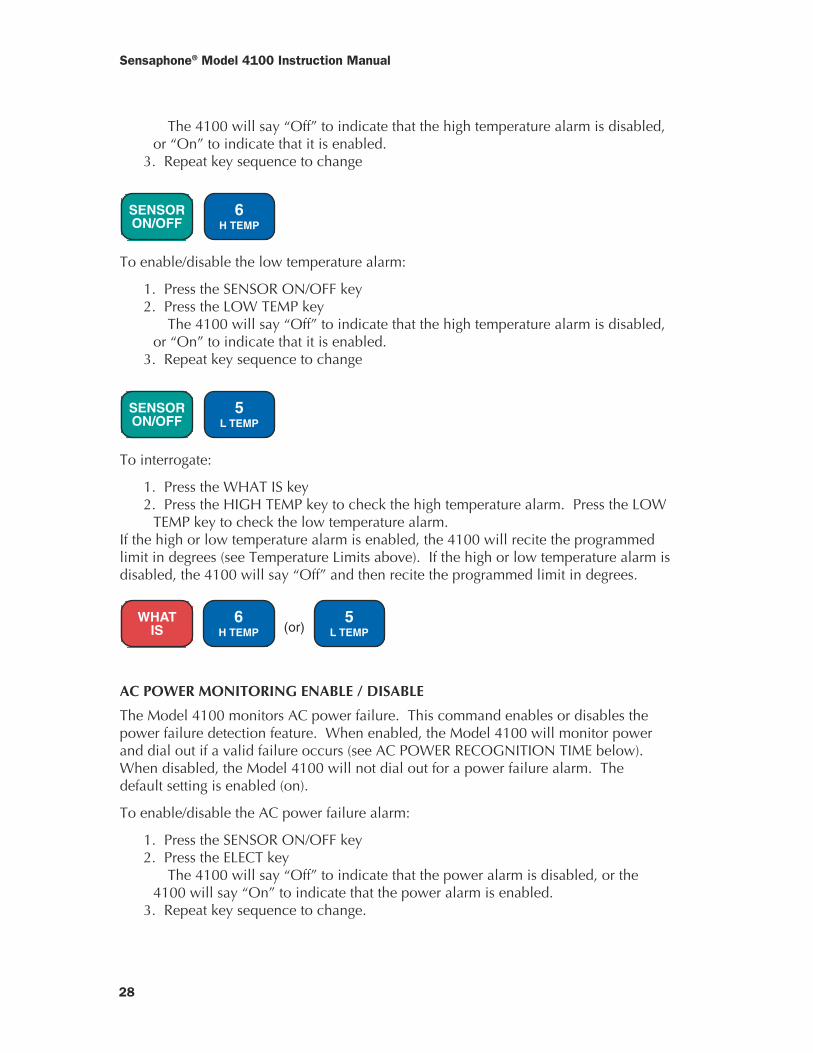
This feature allows you to enable or disable the dialout for the high and low tempera-ture alarms. When a high or low temperature alarm is enabled, it will cause a dialoutfor an alarm. When a high or low temperature alarm is disabled, it will not cause adialout. The default is enabled (on).
To enable/disable the high temperature alarm:
1. Press the SENSOR ON/OFF key2. Press the HIGH TEMP key
Sensaphone® Model 4100 Instruction Manual
28
The 4100 will say “Off” to indicate that the high temperature alarm is disabled,or “On” to indicate that it is enabled.
3. Repeat key sequence to change
SENSORON/OFF
6H TEMP
To enable/disable the low temperature alarm:
1. Press the SENSOR ON/OFF key2. Press the LOW TEMP key
The 4100 will say “Off” to indicate that the high temperature alarm is disabled,or “On” to indicate that it is enabled.
3. Repeat key sequence to change
SENSORON/OFF
5L TEMP
To interrogate:
1. Press the WHAT IS key2. Press the HIGH TEMP key to check the high temperature alarm. Press the LOW
TEMP key to check the low temperature alarm.If the high or low temperature alarm is enabled, the 4100 will recite the programmedlimit in degrees (see Temperature Limits above). If the high or low temperature alarm isdisabled, the 4100 will say “Off” and then recite the programmed limit in degrees.
WHATIS
6H TEMP (or)
5L TEMP
AC POWER MONITORING ENABLE / DISABLE
The Model 4100 monitors AC power failure. This command enables or disables thepower failure detection feature. When enabled, the Model 4100 will monitor powerand dial out if a valid failure occurs (see AC POWER RECOGNITION TIME below).When disabled, the Model 4100 will not dial out for a power failure alarm. Thedefault setting is enabled (on).
To enable/disable the AC power failure alarm:
1. Press the SENSOR ON/OFF key2. Press the ELECT key
The 4100 will say “Off” to indicate that the power alarm is disabled, or the4100 will say “On” to indicate that the power alarm is enabled.
3. Repeat key sequence to change.
29
Chapter 4: Alarm Programming
SENSORON/OFF
7ELECT.
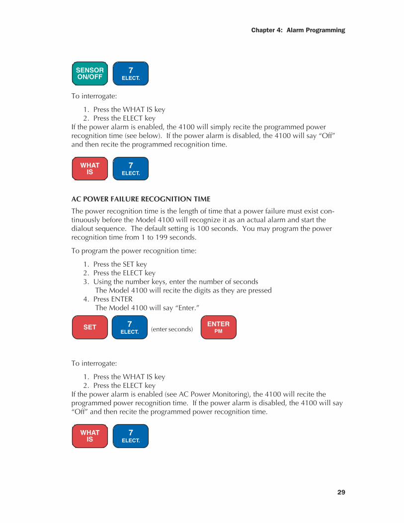
To interrogate:
1. Press the WHAT IS key2. Press the ELECT key
If the power alarm is enabled, the 4100 will simply recite the programmed powerrecognition time (see below). If the power alarm is disabled, the 4100 will say “Off”and then recite the programmed recognition time.
WHATIS
7ELECT.
AC POWER FAILURE RECOGNITION TIME
The power recognition time is the length of time that a power failure must exist con-tinuously before the Model 4100 will recognize it as an actual alarm and start thedialout sequence. The default setting is 100 seconds. You may program the powerrecognition time from 1 to 199 seconds.
To program the power recognition time:
1. Press the SET key2. Press the ELECT key3. Using the number keys, enter the number of seconds
The Model 4100 will recite the digits as they are pressed4. Press ENTER
The Model 4100 will say “Enter.”
SET 7
ELECT. (enter seconds) ENTER
PM
To interrogate:
1. Press the WHAT IS key2. Press the ELECT key
If the power alarm is enabled (see AC Power Monitoring), the 4100 will recite theprogrammed power recognition time. If the power alarm is disabled, the 4100 will say“Off” and then recite the programmed power recognition time.
WHATIS
7ELECT.

Sensaphone® Model 4100 Instruction Manual
30
POWER-OFF TIME ACCUMULATOR
Each time the AC power fails, the Sensaphone accumulates the time in its memory. Itthen will state the total amount of time that the power has failed in its status report.The off-time accumulator will calculate the length of power failure for 255 minutes and59 seconds. After that, the unit will reset to 0. If the AC power and the battery back-up fail, the accumulator will reset to 0. To manually reset the power-off time, pressOFF, and then ON.
HIGH SOUND ALARM ENABLE / DISABLE
The Model 4100 monitors sound through the built-in microphone. When the currentsound level suddenly exceeds the normal sound level, the high sound alarm causes theModel 4100 to dial out. The increased sound level must exist for at least eight sec-onds. The default for the high sound alarm is enabled (on). The microphone is alsoused to listen in to on-site sounds. See Chapter 3, “Listen-In Time,” for settings.NOTE: Disabling the sound alarm does not affect listen-in capability.
To enable/disable the high sound alarm:
1. Press the SENSOR ON/OFF key2. Press the SOUND key
The 4100 will say “Off” to indicate disabled. The 4100 will say “On” toindicate enabled.
3. Repeat key sequence to change.
SENSORON/OFF
8SOUND
To interrogate:
1. Press the WHAT IS key2. Press the SOUND key
If the high sound alarm is enabled, the 4100 will recite the listen-in time programmed.If the high sound alarm is disabled, the 4100 will say “Off” and then will recite thelisten-in time programmed.
WHATIS
8SOUND
31
Chapter 4: Alarm Programming
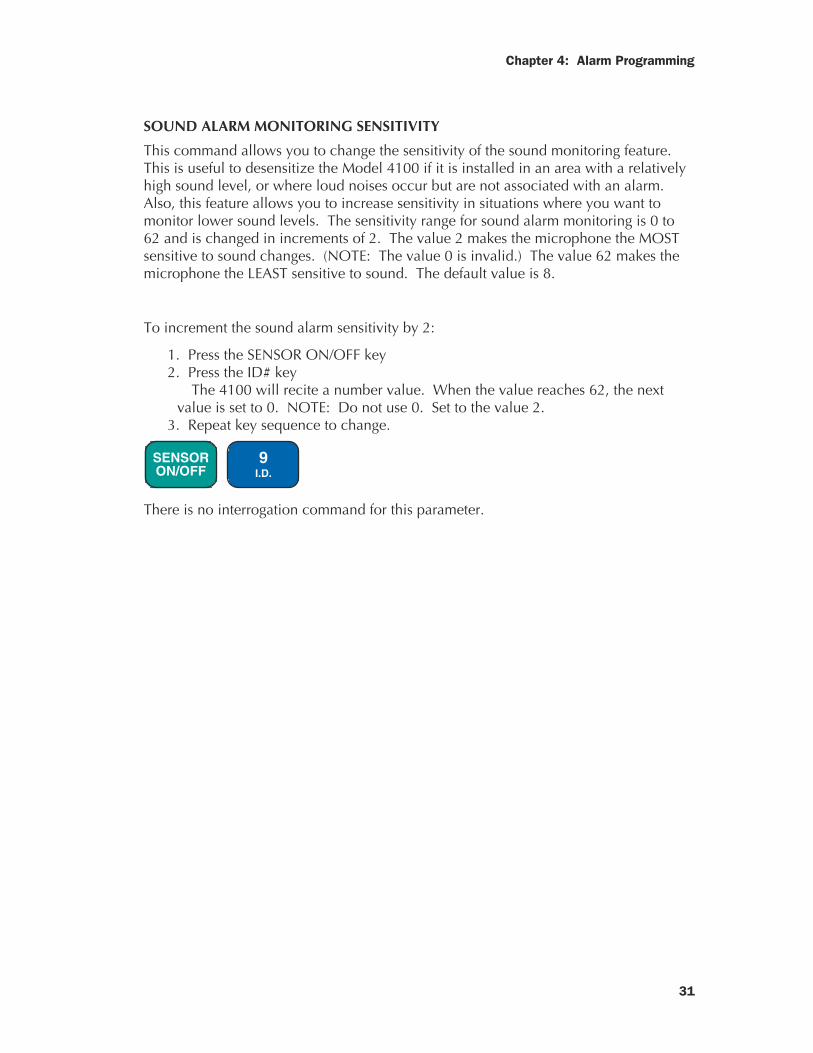
SOUND ALARM MONITORING SENSITIVITY
This command allows you to change the sensitivity of the sound monitoring feature.This is useful to desensitize the Model 4100 if it is installed in an area with a relativelyhigh sound level, or where loud noises occur but are not associated with an alarm.Also, this feature allows you to increase sensitivity in situations where you want tomonitor lower sound levels. The sensitivity range for sound alarm monitoring is 0 to62 and is changed in increments of 2. The value 2 makes the microphone the MOSTsensitive to sound changes. (NOTE: The value 0 is invalid.) The value 62 makes themicrophone the LEAST sensitive to sound. The default value is 8.
To increment the sound alarm sensitivity by 2:
1. Press the SENSOR ON/OFF key2. Press the ID# key
The 4100 will recite a number value. When the value reaches 62, the nextvalue is set to 0. NOTE: Do not use 0. Set to the value 2.
3. Repeat key sequence to change.
SENSORON/OFF
9I.D.
There is no interrogation command for this parameter.

Sensaphone® Model 4100 Instruction Manual
32
33
Chapter 5: Call-in Commands
CHAPTER 5
CALL-IN COMMANDS
The following two functions are call-in commands. This means that to utilize them youmust call the Model 4100 to execute the command. These features are: alarm ac-knowledgment and the status report. You may use either a pulse (rotary) or touch-tonephone.
ALARM ACKNOWLEDGMENT
When the Model 4100 dials out with an alarm message, it will request acknowledg-ment before hanging up. Acknowledgment indicates to the unit that the alarm messagehas been received. Upon acknowledgment, the Model 4100 will cease the dialoutsequence.
There are three ways that an alarm can be acknowledged: locally, by touch-tonephone, or by callback acknowledgment.
1. Local acknowledgment: To acknowledge an alarm locally, press any key on thekeypad. Avoid pressing the OFF key because that will disable the unit.
2. Touch-tone acknowledgment: This method can only be used on a touch-tonetelephone. At the end of the alarm dialout message, the Model 4100 says “Indicateyou have received warning message ...” You have 5 seconds to enter the code “555.”
To do this, press the number key 5 on the touch-tone phone keypad three times. TheModel 4100 will say: “Warning message received by telephone number (last numberdialed).” The unit will then hang up and stop the dialout sequence.
If you enter the wrong code or did not enter it within 5 seconds, the 4100 will say:“Dial telephone number (programmed unit phone number) within 60 seconds.” The4100 will hang up. The alarm will not be acknowledged. You have 60 seconds to callthe unit back to acknowledge the alarm. Hang up, get a dial tone and dial the 4100’sphone number.
3. Callback acknowledgment: This feature allows you to call in to the Model 4100from a touch-tone or pulse phone to acknowledge the alarm.
To use callback acknowledgment, call the unit back within 60 seconds after receivingthe alarm call. If you have TAD enabled (see Chapter 3, “Rings Until Answer & TADCompatibility”), the Model 4100 will answer the phone on the first ring before theanswering device. If TAD is disabled, the phone must ring 10 times. This is a precau-tion against a random alarm acknowledgment. When the 4100 answers the callback, itwill give a status report, then say “Warning message received by ...” and recite thetelephone number that it last dialed. It will stop the dialout sequence for this alarm.
Sensaphone® Model 4100 Instruction Manual
34
STATUS REPORT
The status report feature allows you to call in to the Model 4100 and check the tem-perature, alarm and power status. The unit will answer after the programmed ringsuntil answer. If any alarm conditions exist, the alarm message will be recited. You canalso listen in to on-site sounds.
The following is an example of what the unit will recite during a status report:
Hello
This is telephone number 555-1234 (User-programmed unit phone number)
The time is 12:15 PM (Current time)
Alert condition OK (Alarm status. Other responses: 1 EXISTS, 2 EXISTS, 3 EXISTS, 4EXISTS)
The temperature is 70 degrees (Current temperature)
OK (Temperature alarm condition. Other responses: The temperature is high/low.)
Two (Says this only if a remote temperature sensor is attached to the AUX TEMPinput.)
The temperature is 70 degrees (Says this only if a remote temperature sensor isattached to the AUX TEMP input.)
The electricity is ON (Power status. Other response: OFF)
Battery condition OK (Backup battery condition. Other responses: Battery conditionlow, replace battery.)
Sound level OK (Sound level status. Other response: HIGH)
NO NUMBER (Says this only if no dialout phone numbers have been pro-grammed.)
Listen to the sound level for 10 seconds (User-programmed listen-in time)
The Model 4100 repeats the status report once more and then hangs up.
Have a good day.
35
Chapter 6: Output
CHAPTER 6
THE OUTPUT
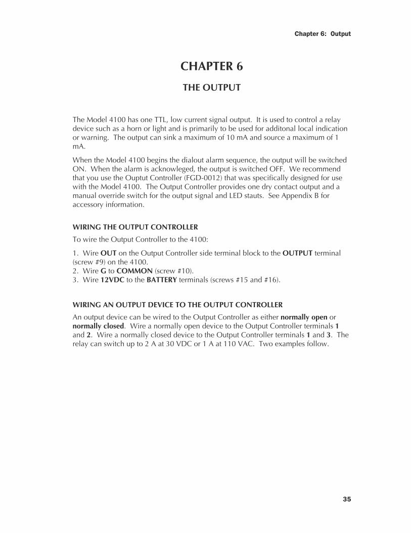
The Model 4100 has one TTL, low current signal output. It is used to control a relaydevice such as a horn or light and is primarily to be used for additonal local indicationor warning. The output can sink a maximum of 10 mA and source a maximum of 1mA.
When the Model 4100 begins the dialout alarm sequence, the output will be switchedON. When the alarm is acknowleged, the output is switched OFF. We recommendthat you use the Ouptut Controller (FGD-0012) that was specifically designed for usewith the Model 4100. The Output Controller provides one dry contact output and amanual override switch for the output signal and LED stauts. See Appendix B foraccessory information.
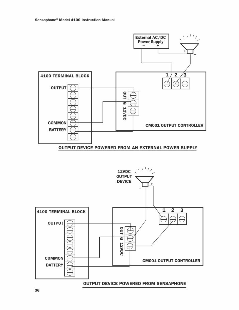
WIRING THE OUTPUT CONTROLLER
To wire the Output Controller to the 4100:
1. Wire OUT on the Output Controller side terminal block to the OUTPUT terminal(screw #9) on the 4100.2. Wire G to COMMON (screw #10).3. Wire 12VDC to the BATTERY terminals (screws #15 and #16).
WIRING AN OUTPUT DEVICE TO THE OUTPUT CONTROLLER
An output device can be wired to the Output Controller as either normally open ornormally closed. Wire a normally open device to the Output Controller terminals 1and 2. Wire a normally closed device to the Output Controller terminals 1 and 3. Therelay can switch up to 2 A at 30 VDC or 1 A at 110 VAC. Two examples follow.
Sensaphone® Model 4100 Instruction Manual
36
1 2 3
OUTPUT
COMMON
BATTERY
OU
T G 1
2V
DC
CM001 OUTPUT CONTROLLER
External AC/DCPower Supply
++
–
–
4100 TERMINAL BLOCK
1 2 34100 TERMINAL BLOCK
OUTPUT
COMMON
BATTERY
OU
T G 1
2V
DC
CM001 OUTPUT CONTROLLER
+–
12VDCOUTPUTDEVICE
OUTPUT DEVICE POWERED FROM SENSAPHONE
OUTPUT DEVICE POWERED FROM AN EXTERNAL POWER SUPPLY
37
Chapter 7: Programming Summary
CHAPTER 7
PROGRAMMING SUMMARY
After the Model 4100 has been completely installed, you are ready to begin program-ming the unit. The following is a recommended sequence for the programmingcommands. Refer to the programming chapters 3 and 4 for explanation on how to useeach command. This section is intended to help you understand the commands andorganize your programming.
MONITORING FUNCTIONS
1. Disable inputs 1-3, 4 (AUX TEMP). This action will allow you to wire the drycontact inputs without tripping an alarm dialout.
2. Wire inputs 1-4. See INSTALLATION.
3. Configure inputs as normally opened or normally closed. This command deter-mines what will be the normal or alarm state for each input 1-4. When you set the IDnumber, the present open/closed state of your sensors will be considered normal. Forexample, if you have input 1 wired as a closed input, setting the ID number will makeit normally closed. If the input is opened, an alarm will result.
4. Enable inputs 1-4. The inputs are now operational and monitoring chosen condi-tions.
5. Disable high/low temperature inputs. This will allow you to set limits withoutcausing an alarm dialout.
6. Set high and low temperature limits. Be careful not to set the temperature limits tooclose to normal room temperature to avoid dialouts for minor/temporary changes intemperature.
7. Enable temperature inputs. The temperature inputs are now operational.
8. Enable or disable AC power monitoring. The Model 4100 is capable of monitoringAC power failure. This feature is built-in, no external wiring is required. You canenable or disable the power detection. When enabled, the Model 4100 will dial outfor a power failure. When disabled, the 4100 will not dial out if a power failureoccurs.
9. Power recognition time. This is the length of time a power failure must exist beforethe 4100 considers it an alarm.
10. Enable or disable high sound level alarm. The Model 4100 monitors soundthrough the built-in microphone. When the current sound level suddenly exceeds thenormal sound level, the high sound alarm causes the Model 4100 to dial out. Whendisabled, the 4100 will not dial out for high sound.
Sensaphone® Model 4100 Instruction Manual
38
11. Sensitize/desensitize sound monitoring. This command allows you to make themicrophone more sensitive or less sensitive to sound at the unit location. This helps toeliminate false sound alarms if the sound level is normally high.
COMMUNICATIONS FUNCTIONS
The Model 4100 is now prepared for alarm monitoring. Next, you must program yourphone numbers and related dialing specifications.
1. Dialout telephone numbers. The Model 4100 can dial up to 4 phone numbers, 32digits each. These phone numbers are dialed sequentially, so program the first numberyou want called as Phone #1, the second as Phone #2, etc.
2. Tone or pulse dialing. The Model 4100’s phone numbers can be dialed out ineither Tone or pulse. This feature is programmed directly into your dialout Phonenumbers.
3. Special dialing. The 4100 is capable of dialing out to some special phone andbeeper systems that require pound (#) or asterisk (*) tones as part of the phone number.Remember that each # or * counts as one digit toward the total of 32 digits.
4. Rings until answer. This parameter determines how many times the 4100 will allowthe phone to ring before answering. For example, if you set this to 4, the 4100 willwait 4 rings and then answer when you call in. This feature is also used in conjunctionwith the Telephone Answering Device (TAD) compatibility.
5. TAD compatibility. The Model 4100 can operate on the same phone line as othertelephone answering devices such as a modem or answering machine. Enable thisfeature only if an answering device in on the same phone line as the 4100. See pages18 -19 for more information.
6. The unit ID number. This 32-digit number should be programmed as the unitphone number. Programming this number also establishes the normal condition of thealert inputs.
7. Local voice mute. This parameter allows you to mute the local voice when theModel 4100 dials out for an alarm or is called for a status report. When the mute is on,the dialout alarm messages and call-in status messages will not be heard at the monitorsite. When the mute is off, the Model 4100 will repeat the message locally as well asover the phone.
8. Time. This command allows you to set the 4100’s built-in clock.
9. Listen-in time. The Model 4100 allows you to listen in to sounds at the monitor sitethrough its built-in microphone when you call in for a status report. This parameterallows you to determine the amount of time for sound monitoring.
10. Security code. You may program a 4-digit security code to prevent unauthorizedaccess to the 4100’s programming. The security code locks the keyboard for program-ming but allows interrogation.
47
Appendix A: Checking for Proper Operation
APPENDIX AChecking your Sensaphone for Proper Operation
We recommend that you test your Sensaphone weekly to be sure it is functioningproperly. This will ensure that when a problem arises the Sensaphone will be ready toalert the appropriate personnel.
There are several tests that can be performed:
1) Call the unit and listen to the Status Report. This will test the unit’s ability toanswer the phone and speak a message. It will also verify that all of the inputs arereading properly, the alarm conditions are OK, the electricity is on, the micro-phone is functioning, and the battery is OK.
2) Create an alarm on each input and allow the unit to contact all programmedtelephone numbers. This will make sure that the Sensaphone is programmedproperly. It will also prepare personnel to respond appropriately when theyreceive a call from the Sensaphone.
3) Test the battery by unplugging the AC adapter and making sure that the Sensa-phone continues to function. Press WHAT IS, then STATUS on the keypad, andlisten to the status report. Make sure the report states that “the electricity is off”and “battery condition OK”. Keep the AC adapter unplugged so that a PowerFailure alarm occurs. Allow the unit to dial all programmed telephone numberswhile running on battery backup. Plug in the AC adapter after the unit has fin-ished dialing all of the telephone numbers.
4) If you are using your Sensaphone to listen for a smoke alarm, then be sure to testthe smoke alarm to make sure that the Sensaphone picks up the audible signaland triggers a high-sound-level alarm. Allow the unit to dial all programmedtelephone numbers.

Sensaphone® Model 4100 Instruction Manual
48
49
Appendix B: Troubleshooting
APPENDIX BTROUBLESHOOTING
Problems with the Model 4100 can range from simply making sure the unit is pluggedin to lightning damage. This appendix is provided to help you pinpoint and solvefunctioning problems. It is divided into the common areas where problems occur.They are:
Communications / Dialout problems Incorrect temperature readings Microphone problems Monitoring problems
The following pages describe problems in these areas, possible causes and solutions. Ifthe unit still does not work after you have tried the following solutions, call our Techni-cal Service Department
Sensaphone® Model 4100 Instruction Manual
50
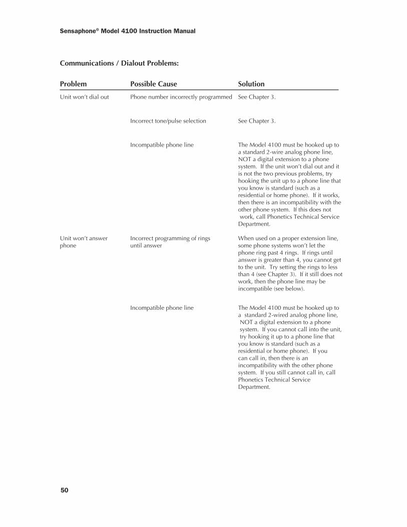
Communications / Dialout Problems:
Problem Possible Cause Solution
Unit won’t dial out Phone number incorrectly programmed See Chapter 3.
Incorrect tone/pulse selection See Chapter 3.
Incompatible phone line The Model 4100 must be hooked up toa standard 2-wire analog phone line,NOT a digital extension to a phonesystem. If the unit won’t dial out and itis not the two previous problems, tryhooking the unit up to a phone line thatyou know is standard (such as aresidential or home phone). If it works,then there is an incompatibility with theother phone system. If this does not work, call Phonetics Technical ServiceDepartment.
Unit won’t answer Incorrect programming of rings When used on a proper extension line,phone until answer some phone systems won’t let the
phone ring past 4 rings. If rings untilanswer is greater than 4, you cannot getto the unit. Try setting the rings to lessthan 4 (see Chapter 3). If it still does notwork, then the phone line may beincompatible (see below).
Incompatible phone line The Model 4100 must be hooked up toa standard 2-wired analog phone line, NOT a digital extension to a phone system. If you cannot call into the unit, try hooking it up to a phone line thatyou know is standard (such as aresidential or home phone). If youcan call in, then there is anincompatibility with the other phonesystem. If you still cannot call in, callPhonetics Technical ServiceDepartment.
51
Appendix B: Troubleshooting
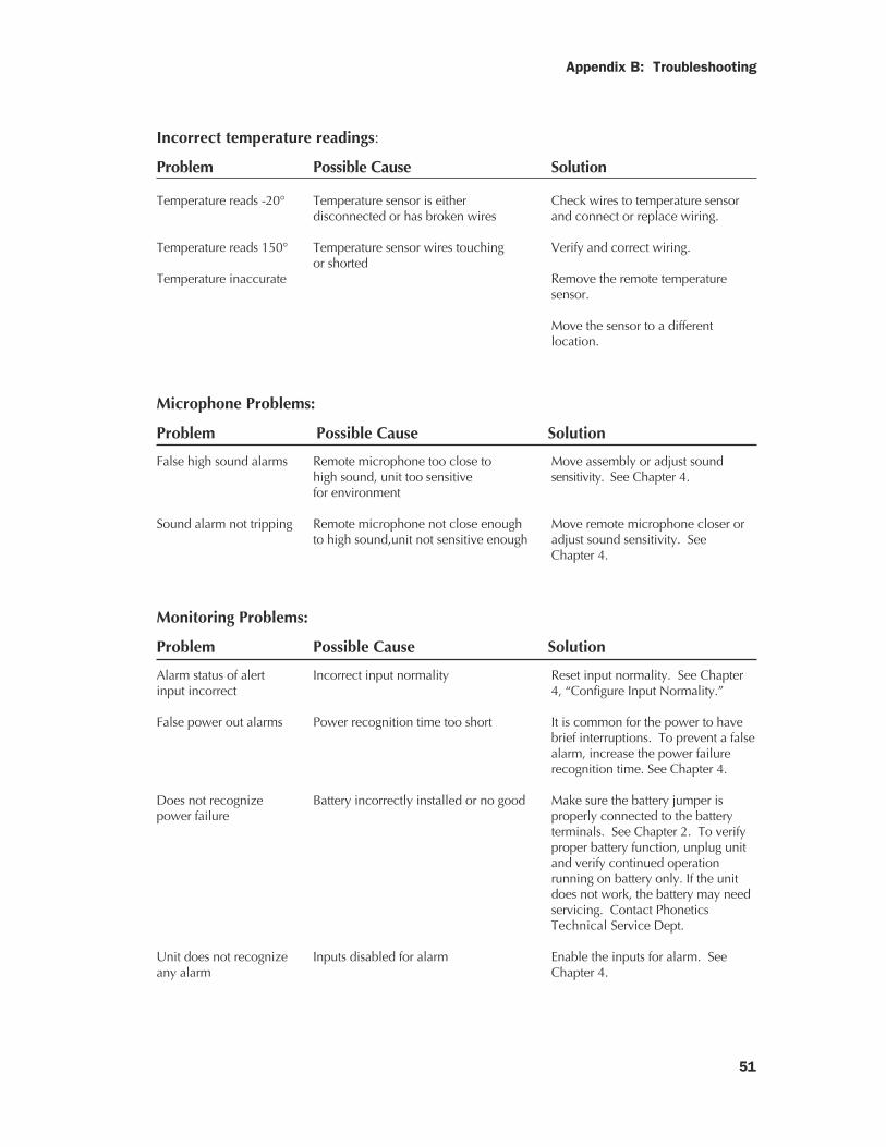
Incorrect temperature readings:
Problem Possible Cause Solution
Temperature reads -20° Temperature sensor is either Check wires to temperature sensordisconnected or has broken wires and connect or replace wiring.
Temperature reads 150° Temperature sensor wires touching Verify and correct wiring.or shorted
Temperature inaccurate Remove the remote temperaturesensor.
Move the sensor to a differentlocation.
Microphone Problems:
Problem Possible Cause Solution
False high sound alarms Remote microphone too close to Move assembly or adjust soundhigh sound, unit too sensitive sensitivity. See Chapter 4.for environment
Sound alarm not tripping Remote microphone not close enough Move remote microphone closer orto high sound,unit not sensitive enough adjust sound sensitivity. See
Chapter 4.
Monitoring Problems:
Problem Possible Cause Solution
Alarm status of alert Incorrect input normality Reset input normality. See Chapterinput incorrect 4, “Configure Input Normality.”
False power out alarms Power recognition time too short It is common for the power to havebrief interruptions. To prevent a falsealarm, increase the power failurerecognition time. See Chapter 4.
Does not recognize Battery incorrectly installed or no good Make sure the battery jumper ispower failure properly connected to the battery
terminals. See Chapter 2. To verifyproper battery function, unplug unitand verify continued operationrunning on battery only. If the unitdoes not work, the battery may needservicing. Contact PhoneticsTechnical Service Dept.
Unit does not recognize Inputs disabled for alarm Enable the inputs for alarm. Seeany alarm Chapter 4.

Sensaphone® Model 4100 Instruction Manual
52
Battery drains prematurely Unit turned off and unplugged The battery is still drained and theunit consumes full power when theunit is shut off and unplugged. Ifyou are not using the unit, discon-nect the battery jumper. SeeChapter 2.
Unit does not seem to Various causes Try starting from scratch. Discon-respond properly nect the battery jumper and unplug
the unit. Allow the unit to rest for afew minutes. Plug the unit back inand reconnect the battery jumper. Ifthe unit still does not work, callPhonetics Technical Service.
53
Appendix C: Accessories
APPENDIX CACCESSORIES
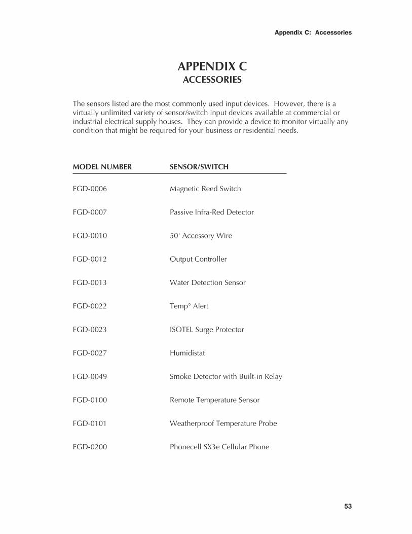
The sensors listed are the most commonly used input devices. However, there is avirtually unlimited variety of sensor/switch input devices available at commercial orindustrial electrical supply houses. They can provide a device to monitor virtually anycondition that might be required for your business or residential needs.
MODEL NUMBER SENSOR/SWITCH
FGD-0006 Magnetic Reed Switch
FGD-0007 Passive Infra-Red Detector
FGD-0010 50' Accessory Wire
FGD-0012 Output Controller
FGD-0013 Water Detection Sensor
FGD-0022 Temp° Alert
FGD-0023 ISOTEL Surge Protector
FGD-0027 Humidistat
FGD-0049 Smoke Detector with Built-in Relay
FGD-0100 Remote Temperature Sensor
FGD-0101 Weatherproof Temperature Probe
FGD-0200 Phonecell SX3e Cellular Phone
55
Appendix D: Error Messages
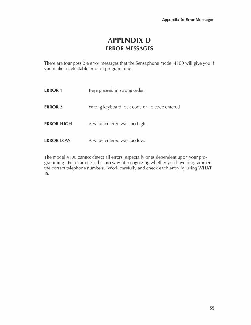
APPENDIX DERROR MESSAGES
There are four possible error messages that the Sensaphone model 4100 will give you ifyou make a detectable error in programming.
ERROR 1 Keys pressed in wrong order.
ERROR 2 Wrong keyboard lock code or no code entered
ERROR HIGH A value entered was too high.
ERROR LOW A value entered was too low.
The model 4100 cannot detect all errors, especially ones dependent upon your pro-gramming. For example, it has no way of recognizing whether you have programmedthe correct telephone numbers. Work carefully and check each entry by using WHATIS.
57
Appendix E: Applications
APPENDIX EAPPLICATIONS
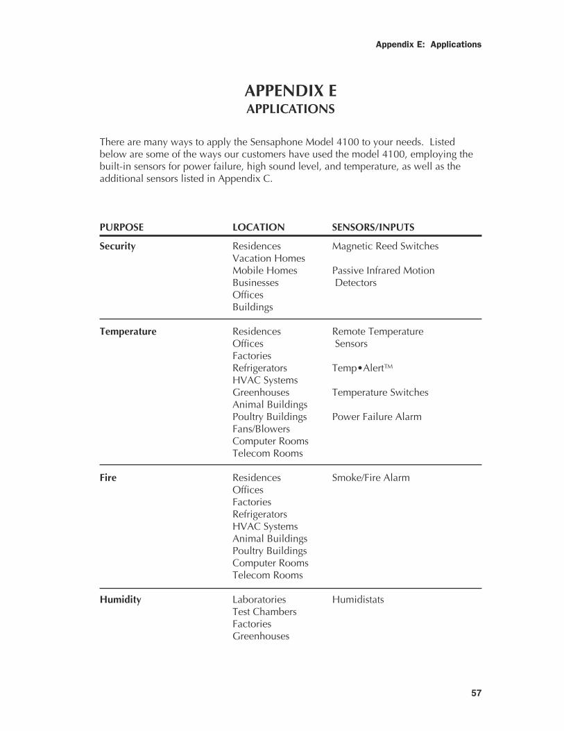
There are many ways to apply the Sensaphone Model 4100 to your needs. Listedbelow are some of the ways our customers have used the model 4100, employing thebuilt-in sensors for power failure, high sound level, and temperature, as well as theadditional sensors listed in Appendix C.
PURPOSE LOCATION SENSORS/INPUTS
Security Residences Magnetic Reed SwitchesVacation HomesMobile Homes Passive Infrared MotionBusinesses DetectorsOfficesBuildings
Temperature Residences Remote TemperatureOffices SensorsFactoriesRefrigerators Temp•Alert™HVAC SystemsGreenhouses Temperature SwitchesAnimal BuildingsPoultry Buildings Power Failure AlarmFans/BlowersComputer RoomsTelecom Rooms
Fire Residences Smoke/Fire AlarmOfficesFactoriesRefrigeratorsHVAC SystemsAnimal BuildingsPoultry BuildingsComputer RoomsTelecom Rooms
Humidity Laboratories HumidistatsTest ChambersFactoriesGreenhouses
59
Appendix F: Returning Unit for Repair
APPENDIX FRETURNING UNIT FOR REPAIR
In the event that the Model 4100 does not function properly and you cannot reprogramit, we suggest that you do the following:
1) Carefully write down your observations of the Model 4100's malfunctioning.
2) Call Technical Service if any instructions are notclear or if you have any questions.
If the unit must be sent to us for servicing, do the following:
1) Unplug the AC power supply from the wall outlet, disconnect the batteryjumper at screws numbered 15 and 16, and disconnect all sensors from the alertinputs. Insert the jumper under screw number 16 and hanging over the postscrew beside it. Tighten screw number 16 to hold the jumper in place duringshipping. Do not try to unscrew or tighten the post screw.
2) Carefully pack unit into its original container or a sturdy shipping box. Becertain to use sufficient cushioning material to avoid damage in transit.
3) To avoid processing delays, be sure to include the following:
a) Your name, address, and phone number
b) Model and Serial numbers
c) A letter explaining the Model 4100's problem

Sensaphone® Model 4100 Instruction Manual
60
1 YEAR LIMITED WARRANTY
1. WARRANTOR: Dealer, Distributor, Manufacturer
2. ELEMENTS OF WARRANTY: This Product is warranted to be free from defects in materialsand craftsmanship with only the limitations and exclusions set out below.
3. WARRANTY AND REMEDY: One-Year Warranty — In the event that the Product does notconform to this warranty at any time during the time of one year from original purchase,warrantor will repair the defect and return it to you at no charge
This warranty shall terminate and be of no further effect at the time the Product is (1) damagedby extraneous cause such as fire, water, lightning, etc. or not maintained as reasonable andnecessary; (2) modified; (3) improperly installed; (4) repaired by someone other than warrantor;(5) used in a manner or purpose for which the Product was not intended; or (6) sold by originalpurchaser.
WARRANTORS’ OBLIGATION UNDER THIS WARRANTY IS LIMITED TO REPAIR OR RE-PLACEMENT OF THE PRODUCT. THIS WARRANTY DOES NOT COVER PAYMENT ORPROVIDE FOR THE REIMBURSEMENT OF PAYMENT OF INCIDENTAL OR CONSEQUEN-TIAL DAMAGES.
It must be clear that the warrantors are not insuring your premises or guaranteeing that therewill not be damage to your person or property if you use this Product. The warrantors shall notbe liable under any circumstances for damage to your person or property or some other personor that person’s property by reason of the sale of this product or its failure to operate in themanner in which it is designed. The warrantors’ liability, if any, shall be limited to the originalcost of the Product. The warrantors assume no liability for installation of the Product and/orinterruptions of the service due to strikes, riots, floods, fire, and/or any cause beyond Seller’scontrol.
4. PROCEDURE FOR OBTAINING PERFORMANCE OF WARRANTY: In the event that theProduct does not conform to this warranty, the Product should be shipped or delivered freightprepaid to a warrantor with evidence of original purchase.
5. LEGAL REMEDIES: This warranty gives you specific legal rights, and you may also haveother rights which vary from state to state to the extent allowed by law expressly in lieu of anyother express or implied warranty, condition, or guarantee.
Effective date 07/01/90Phonetics, Inc.
