seismic behavior and design of precast connections … · seismic behavior and design of precast...
TRANSCRIPT

ARCHITECTURAL ENGINEERING DEPARTMENT SCHOOL OF ARCHITECTURE AND ENVIRONMENTAL DESIGN
CALIFORNIA POLYTECHNIC STATE UNIVERSITY SAN LUIS OBISPO. CAUFORNIA 93407
SEISMIC BEHAVIOR AND DESIGN OF PRECAST FACADES/CLADDINGS & CONNECTIONS IN LOW/MEDIUM-RISE BUILDINGS
FINAL TECHNICAL REPORT
BY DR. SATWANT S. RIHAL PROFESSOR, ARCHITECTURAL ENGINEERING DEPARTMENT
NOVEMBER 1935
SPONSORED BY THE NATIONAL SCIENCE FOUNDATION DIVISION OF CIVIL AND ENVIRONMENTAL ENGINEERING EARTHQUAKE HAZARD MITIGATION PROGRAM
Gt~ANT NO. CEE-841 0543
NSFjENG-88028
REPORT ARCE RSS-1

50272 -101
REPORT DOCUMENTATION 11. ItU'OIn' NO. PAGE NSF/ENG-88028 I:'
Seismic Behavior and Design of Precast Facades/Claddings and November 1988 Connections in Low/Medium-Rise Buildings, Final Technical Report L
7. Auttoor(s)
S.S. Rihal ,. "'rlorminc Orpniz.tion Na ..... nd AOdrna
California Polytechnic State University Architectural Engineering Department San Luis Obispo, CA 93407
1%. $PGnMri". O .... nization H ...... and Add .....
Directorate for Engineering (ENG) Nationa1 Science Foundation 1800 G Street, N.W. Washington, DC 20550
15. ~pplam.nt.ary Not ..
1--------------=---.:..---. _____ c-=-r' __________ _
lL Abstract (Umit: 200 wordS)
L "-"'orm1nc O .... niz.tion ","pot. No.
ARCE R&8-1 10. ~jeCt/TeaklWo", Unit No.
(C)
(G) CEE8410543
11. T1CMt of Raport .. "'riod eov. ... d
14.
Seismic behavior and design of heavy facades/claddings and c~~n2ctions in tuildinqs has been inves~igated and unique cyclic racking tests of representative precast concrete facade/cladding panels and connections have been carried out. Test r0sults consist of cyclic load-displacement curves; time-'history plots of loads~ ::j :i. ':5 I:::' ], \':':\ C E! ;T: (.:.~ n t. '::::. ;; c\ c: c: ~:.:; 1 ::.:':: , .... ~·;;i. t :i. c} r'l ':::. ;i (:;,,; t. C::I;I c:1 Lt j"- :L n ::.1 \~.:,: Et c:: h ,t. (':2 ':::~ t ;: ~'::\ n E:t 3. ":./ '::. :i. ::::. . C) of peak response quantities, e.g., displacements and load-levels reached; estimated rigidities of the cladding panel-connection ~·:·:i. '::::. ~:::. ('-:.:. !T; /:) 1 \/ :~~. t i, n c ;,,- \':2 .;:!. '::::. :L n {,:,:,! 1. ~:::: \/ f:::']' :;;~ c; .. ;:: P f::':' ,:'::1,1< cl:i. ,::'\ ;::: \::; rr; E·:' r:l t. ~:~. C)'f b:l. c;,C: 1:: C \/ C 1 ::::: '::;. t~
::::\'::::. !.'.IE·~11 .:':';\';;::. "l:~h(·:·:: ;·~'E·~J. .:':':\t.:i. c:n':::.!'·'J i j::) f-;(·::!t.l,.'.J(':'::(·:·:!!"'j ci,"-:L + ';::. 1. ;::.·:·:,\/(·:·:·!1':::. E:\r',d lJ(·:·::h~·~\\/:i.~Ji"- c"'F (~ 1. .:::1, ci din (j P ·;::lI"1 :;;.! :1. ..... C CJ n r': C:\ C t~ :i. c· n i·;';i. ::;::;. s::· E-~' ro!::)]. :i. E·:' '::::. II • :0 '~./ n \.~\ en i c t (-~ ;';;. t. :i. j""'i (] \::1 .{:: (:~
representative reduced scale three dimensional model two st6ry
~~:~~;~=a;:~e~~~I~t:9c:~~~~~U:~t~it~e::~t:i~~~~:d~r:~:~~i~~~7::t~ 2Kperimental data on the earthquake resistance and stiffness of cladding connections 30d the overall seismic behavior of cladding connection assemblies.
17. Docu ment Ana 1)11. a. One,;",o",
Earthquakes Joints (junctions) Architectural 'concrete Earthquake resistant structures
II. IdefttlfMrs/~Ended T ......
Seismic behavior Earthquake engineering
11. A".ilability --....m
NTIS cs- Al'CS1-Z39.11)
Buildings Facings Design
Concrete construction Structural engineering Structural design
1.. Security CI .... ('Thi. ","port) %1. No. of ......
/7;;"'"
OfITIOHAL. FO"''' 272 (4-77) (Forme", NTI5-]S) Dep.rt .... nt of Comlft..c.
SUMMARY
Seismic behavior and design of heavy facades/claddings and connections in buildings has been investigated, and unique cyclic racking tests of representative precast concrete facade/cladding panels and connections have been carried out. During the first major phase of the research project current practices for design and detailing of heavy facade/claddings and their connections to supporting structural systems, were evaluated. In consultation with practicing architects, engineers, researchers and facade/cladding manufacturers, state-of-the-art data for facade/cladding design, detailing and erection practices was compiled. Available data on the performance of building facade/cladding during previous destructive earthquakes including the recent Mexico City Earthquake of September 1985 was evaluated. Analytical and experimental techniques of modeling the seismic behavior of heavy precast concrete facade/cladding panels and connections have been investigated. The role of modern testing methodology in assessing the seismic behavior of building facades/claddings and connections has been evaluated. Pilot static tests of typical ductile (push-pull) cladding connections were carried out to investigate the strength and behavior of these connections. Cyclic in-plane racking test of a full-size precast concrete cladding panel with bearing connections at the bottom and ductile (push-pull) connections at the top, representative of California current practices, has been carried out. Test results consist of cyclic load-displacement curves; time-history plots of loads, displacements, accelerations, etc., during each test; analysis of peak response quantities, e.g., displacements and load-levels reached; estimated rigidities of the cladding panel-connection assembly at increasing levels of peak displacements of block cycles; as well as the relationship between drift levels and behavior of cladding panel-connection assemblies. Dynamic testing of a representative reduced scale three dimensional model two story steel-framed building structure with and without precast concrete cladding panels, was carried out. Results provide quantitative experimental data on the earthquake resistance and stiffness of cladding connections and the overall seismic behavior of cladding connection assemblies. The test results obtained will help develop improved and more realistic analytical modeling of building structural systems interacting with heavy facades/cladding and connection systems in low/medium-rise buildings during earthquakes.

J
ACKNOWLEDGEMENTS
This research work was supported by the National Science Foundation under Grant No. CEE-8410543, Dr. A.J. Eggenberger, Program Manager. This support is gratefully acknowledged. Any opinions, findings and conclusions or recommendations expressed in this report are those of the authors and do not necessarily reflect the views of the National Science Foundation.
Dr. Satwant Rihal, Professor, Architectural Engineering Department, served as the principal investigator and project director for this research project.
Author acknowledges the assistance and contribution of Dr. Gary Granneman of the ET/EL Department, Cal Poly State University, San Luis Obispo, California, for testing and instrumentation; student research assistants Kurt Clandening, Dwayne Slavin and John Cotton during the course of this research investigation. The contribution of Mr. John Cotton, in the analytical evaluation of test results is acknowledged.
The assistance of Mr. Ed Knowles, Vice-president, Lafayette Manufacturing Inc., Hayward, California, for providing precast concrete cladding panel specimens for this research project is acknowledged and sincerely appreciated.
i i
TABLE OF CONTENTS Page
SUMMARY
ACKNOWLEDGEMENTS ii
LIST OF FIGURES AND PHOTOGRAPHS v
LIST OF FIGURES AND PHOTOGRAPHS - APPENDICES vii
LIST OF TABLES xi
CHAPTER 1: INTRODUCTION 1
CHAPTER 2: BUILDING FACADES/CLADDINGS 2
2.1 BACKGROUND 2 2.2 CLASSIFICATION OF FACADES/CLADDINGS 8 2.3 DESIGN ISSUES 9
CHAPTER 3: SCOPE AND OBJECTIVES 12
CHAPTER 4: LITERATURE REVIEW 13
CHAPTER 5: FACADE/CLADDING PERFORMANCE DURING PREVIOUS EARTHQUAKES 14
CHAPTER 6: SEISMIC DESIGN CODES AND REGULATIONS 26
CHAPTER 7: REVIEW OF CURRENT DESIGN AND DETAILING PRACTICES 32
7.1 FACADE/CLADDING PANELS 7.2 CONNECTIONS
CHAPTER 8: TESTING PROGRAM 42
GENERAL 42
8.1 TEST I TESTING OF LATERAL (THREADED-ROD) 42 CONNECTIONS
8.1.1 TEST OBJECTIVE 8.1.2 DESCRIPTION OF TEST SPECIMEN 8.1.3 TEST SET-UP AND PROCEDURE 8.1.4 TEST RESULTS 44
8.2 TEST II CYCLIC TESTS OF PRECAST CONCRETE CLADDING 45 PANEL AND CONNECTION ASSEMBLY
8.2.1 TEST OBJECTIVE 8.2.2 DESCRIPTION OF TEST SPECIMEN 8.2.3 TEST SET-UP AND PROCEDURE 8.2.4 TEST RESULTS 51-52
iii
· J
8.3 TEST III DYNAMIC TESTING OF TWO-STORY STEEL 53 MOMENT-RESISTING FRAME STRUCTURE WITH AND WITHOUT PRECAST CONCRETE CLADDING PANELS
8.3.1 TEST OBJECTIVE 53 8.3.2 DESCRIPTION OF TEST SPECIMEN 53 8.3.3 DYNAMIC TEST SET-UP AND PROCEDURE 54 8.3.4 TEST RESULTS 55
CHAPTER 9: ANALYTICAL MODELLING OF FACADE/CLADDING AND CONNECTIONS 60
CHAPTER 10: SUMMARY OF RESULTS AND CONCLUSIONS
BIBLIOGRAPHY
APPENDIX A TEST I
DRAWINGS OF TEST SET-UP AND TEST SPECIMEN PHOTOGRAPHS GRAPHS OF TEST RESULTS
APPENDIX B TEST II
DRAWINGS OF TEST SET-UP AND TEST SPECIMEN PHOTOGRAPHS TIME HISTORY PLOTS GRAPHS OF TEST RESULTS
APPENDIX C TEST III
PHOTOGRAPHS DRAWINGS OF TEST STRUCTURE AND CLADDING PANELS & CONNECTION DETAILS TYPICAL OUTPUT FROM ANALYZER
iv
63
71
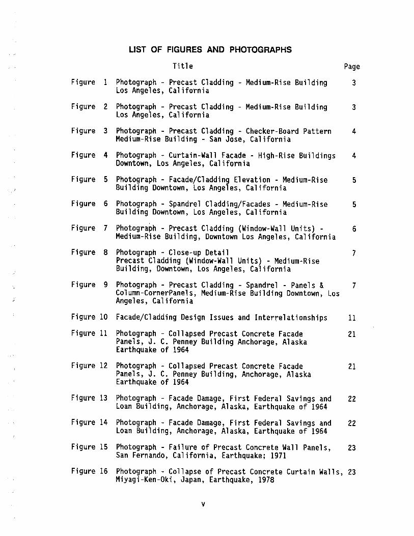
LIST OF FIGURES AND PHOTOGRAPHS
Title Page
Figure 1 Photograph - Precast Cladding - Medium-Rise Building 3 Los Angeles, Cal iforni a
Figure 2 Photograph - Precast Cladding - Medium-Rise Building 3 Los Angeles, Cal ifornia
Figure 3 Photograph - Precast Cladding - Checker-Board Pattern 4 Medium-Rise Building - San Jose, California
Figure 4 Photograph - Curtain-Wall Facade - High-Rise Buildings 4 Downtown, Los Angeles, California
Figure 5 Photograph - Facade/Cladding Elevation - Medium-Rise 5 Building Downtown, Los Angeles, California
Figure 6 Photograph - Spandrel Cladding/Facades - Medium-Rise 5 Building Downtown, Los Angeles, California
Figure 7 Photograph - Precast Cladding (Window-Wall Units) - 6 Medium-Rise Building, Downtown Los Angeles, California
Figure 8 Photograph - Close-up Detail 7 Precast Cladding (Window-Wall Units) - Medium-Rise Building, Downtown, Los Angeles, California
Figure 9 Photograph - Precast Cladding - Spandrel - Panels & 7 Column-CornerPanels, Medium-Rise Building Downtown, Los Angeles, California
Figure 10 Facade/Cladding Design Issues and Interrelationships 11
Figure 11 Photograph - Collapsed Precast Concrete Facade Panels, J. C. Penney Building Anchorage, Alaska Earthquake of 1964
21
Figure 12 Photograph - Collapsed Precast Concrete Facade 21 Panels, J. C. Penney Building, Anchorage, Alaska Earthquake of 1964
Figure 13 Photograph - Facade Damage, First Federal Savings and 22 Loan Building, Anchorage, Alaska, Earthquake of 1964
Figure 14 Photograph - Facade Damage, First Federal Savings and 22 Loan Building, Anchorage, Alaska, Earthquake of 1964
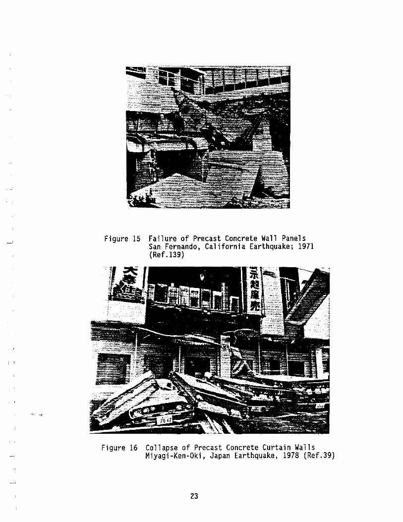
Figure 15 Photograph - Failure of Precast Concrete Wall Panels, 23 San Fernando, California, Earthquake; 1971
Figure 16 Photograph - Collapse of Precast Concrete Curtain Walls, 23 Miyagi-Ken-Oki, Japan, Earthquake, 1978
v
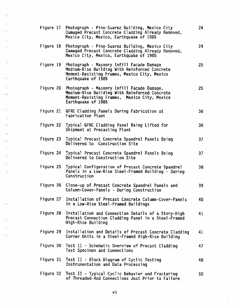
Figure 17 Photograph - Pino-Suarez Building, Mexico City 24 Damaged Precast Concrete Cladding Already Removed, Mexico City, Mexico, Earthquake of 1985
Figure 18 Photograph - Pi no-Suarez Building, Mexico City 24 Damaged Precast Concrete Cladding Already Removed, Mexico City, Mexico, Earthquake of 1985
Figure 19 Photograph - Masonry Infill Facade Damage Medium-Rise Building With Reinforced Concrete Moment-Resisting Frames, Mexico City, Mexico Earthquake of 1985
Figure 20 Photograph - Masonry Infill Facade Damage, Medium-Rise Building With Reinforced Concrete Moment-Resisting Frames, Mexico City, Mexico Earthquake of 1985
25
25
Figure 21 GFRC Cladding Panels During Fabrication at 36 Fabrication Plant
Figure 22 Typical GFRC Cladding Panel Being Lifted for 36 Shipment at Precasting Plant
Figure 23 Typical Precast Concrete Spandrel Panels Being 37 Delivered to Construction Site
Figure 24 Typical Precast Concrete Spandrel Panels Being 37 Delivered to Construction Site
Figure 25 Typical Configuration of Precast Concrete Spandrel 38 Panels in a Low-Rise Steel-Framed Building - During Construction
Figure 26 Close-up of Precast Concrete Spandrel Panels and 39 Column-Cover-Panels - During Construction
Figure 27 Installation of Precast Concrete Column-Cover-Panels 40 in a Low-Rise Steel-Framed Buildings
Figure 28 Installation and Connection Details of a Story-High 41 Precast Connection Cladding Panel in a Steel-Framed High-Rise Building
Figure 29 Installation and Details of Precast Concrete Cladding 41 Corner Units in a Steel-Framed High-Rise Building
Figure 30 Test II - Schematic Overview of Precast Cladding 47 Test Specimen and Connections
Figure 31 Test II - Block Diagram of Cyclic Testing 48 Instrumentation and Data Processing
Figure 32 Test II - Typical Cyclic Behavior and Fracturing 50 of Threaded-Rod Connections Just Prior to Failure
vi
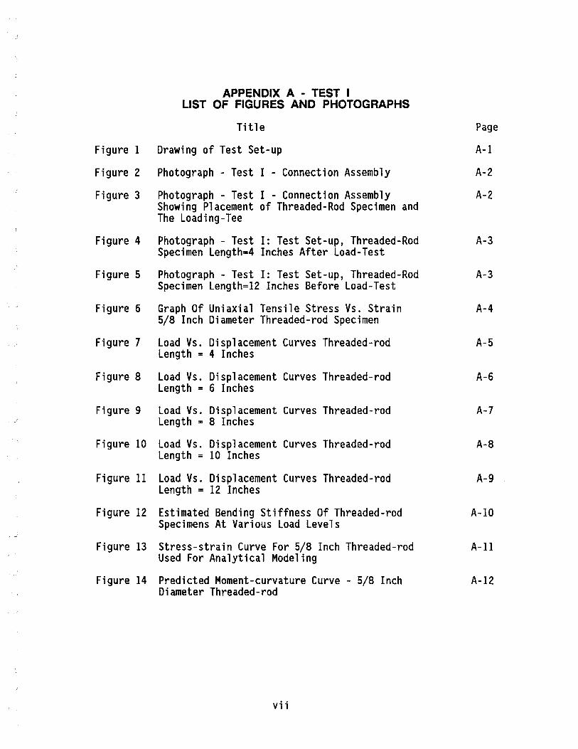
APPENDIX A - TEST I LIST OF FIGURES AND PHOTOGRAPHS
Title
Figure I Drawing of Test Set-up
Figure 2 Photograph - Test I - Connection Assembly
Figure 3 Photograph - Test I - Connection Assembly Showing Placement of Threaded-Rod Specimen and The Loading-Tee
Figure 4 Photograph - Test I: Test Set-up, Threaded-Rod Specimen Length=4 Inches After Load-Test
Figure 5 Photograph - Test I: Test Set-up, Threaded-Rod Specimen Length=12 Inches Before Load-Test
Figure 6 Graph Of Uniaxial Tensile Stress Vs. Strain 5/8 Inch Diameter Threaded-rod Specimen
Figure 7 Load Vs. Displacement Curves Threaded-rod Length = 4 Inches
Figure 8 Load Vs. Displacement Curves Threaded-rod Length = 6 Inches
Figure 9 Load Vs. Displacement Curves Threaded-rod Length = 8 Inches
Figure 10 Load Vs. Displacement Curves Threaded-rod Length = 10 Inches
Figure II Load Vs. Displacement Curves Threaded-rod Length = 12 Inches
Figure 12 Estimated Bending Stiffness Of Threaded-rod Specimens At Various Load Levels
Figure 13 Stress-strain Curve For 5/8 Inch Threaded-rod Used For Analytical Modeling
Figure 14 Predicted Moment-curvature Curve - 5/8 Inch Diameter Threaded-rod
vii
Page
A-I
A-2
A-2
A-3
A-3
A-4
A-S
A-6
A-7
A-8
A-9
A-IO
A-ll
A-12
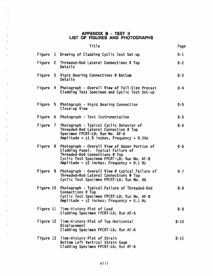
APPENDIX B - TEST II LIST OF FIGURES AND PHOTOGRAPHS
Title
Figure 1 Drawing of Cladding Cyclic Test Set-up
Figure 2 Threaded-Rod lateral Connections @ Top Details
Figure 3 Rigid Bearing Connections @ Bottom Detail s
Figure 4 Photograph - Overall View of Full-Size Precast Cladding Test Specimen and Cyclic Test Set-up
Figure S Photograph - Rigid Bearing Connection Close-up View
Figure 6 Photograph - Test Instrumentation
Figure 7 Photograph - Typical Cyclic Behavior of Threaded-Rod lateral Connection @ Top Specimen FPCRT-lS; Run No. AF-6 Amplitude = ±1.S inches, Frequency = O.IHz
Figure S Photograph - Overall View of Upper Portion of Cladding Panel. Typical Failure of Threaded-Rod Connections @ Top Cyclic Test Specimem FPCRT-lS; Run No. AF-S Amplitude = ±2 inches; Frequency = 0.1 Hz
Figure 9 Photograph - Overall View @ typical Failure of Threaded=Rod lateral Connections @ Top Cyclic Test Specimen FPCRT-l6; Run No. A6
Figure 10 Photograph - Typical Failure of Threaded-Rod Connections @ Top Cyclic Test Specimen FPCRT-LS; Run No. AF-S Amplitude = ±2 inches; Frequency = 0.1 Hz
Figure 11 Time-History Plot of Load Cladding Specimen FPCRT-L6; Run AF-6
Figure 12 Time-History Plot of Top Horizontal Displacement Cladding Specimen FPCRT-L6; Run AF-6
Figure 13 Time-History Plot of Strain Bottom Left Vertical Strain Gage Cladding Specimen FPCRT-l6; Run AF-6
viii
Page
B-1
B-2
B-3
B-4
B-S
B-S
B-6
B-6
B-7
B-S
B-9
B-I0
B-11

Figure 14 Time-History Plot of Strain Bottom Left Horizontal Strain Gage Cladding Specimen FPCRT-L6; Run AF-6
Figure 15 Time-History Plot of Strain Bottom Right Vertical Strain Gage Cladding Specimen FPCRT-L6; Run AF-6
Figure 16 Time-History Plot of Load Cladding Specimen FPCRT-LS; Run B-4
Figure 17 Time-History Plot of Top Horizontal Displacement Cladding Specimen FPCRT-LS; Run B-4
Figure IS Time-History Plot of Strain Bottom Left Vertical Strain Gage Cladding Specimen FPCRT-LS; Run B-4
Figure 19 Time-History Plot of Strain Bottom Left Horizontal Strain Gage Cladding Specimen FPCRT-LS; Run B-4
Figure 20 Time-History Plot of Strain Bottom Right Vertical Strain Gage Cladding Specimen FPCRT-LS; Run B-4
B-12
B-13
B-14
B-15
B-16
B-17
B-1S
Figure 21 Cyclic Load-Displacement Curves B-19 Full Panel Cyclic Racking Test Specimen FPCRT-L6 Run AF-6 Peak Command Displacement = ±1-1/2 inches Frequency = 0.1 Hz
Figure 22 Test II Peak Load vs. Peak Displacement Curves B-20
Figure 23 Test II Peak Lateral Force Resistance vs. B-21 Drift
Figure 24 Graphs of Peak Load Surcharge to Bearing B-22 Connection Angle vs. Drift Test Frequency = 0.1 Hz
Figure 25 Graphs of Peak Load Surcharge to Bearing B-23 Connection Angle vs. Drift Test Frequency = 0.5 Hz
Figure 26 Graphs of Peak Load Surcharge to Studs in B-24 Bearing Connection vs. Drift Test Frequency = 0.1 Hz
Figure 27 Graphs of Peak Load Surcharge to Studs in B-25 Bearing Connection vs. Drift Test Frequency = 0.5 Hz
ix
APPENDIX C - TEST III LIST OF FIGURES AND PHOTOGRAPHS
Title
Figure 1 Photograph - Two-Story Moment-Resisting RigidFrame Test Structure for Dynamic Testing of Cladding and Connections
Figure 2 Photograph - APS Electro-Seis Shaker Positioned on the Floor of Test Structure in the N-S Direction
Figure 3 Photograph - Test Instrumentation HP 3582A Spectrum Analyzer
Figure 4 Photograph - Dynamic Test of Test-Structure without Cladding Panels APS Electro-Seis Shaker Positioned on Floor in the N-S Direction
Figure 5 Photograph - 4-1/2 Inch Thick Precast Cladding Panel Before Attachment to the Test III Steel Test Frame Structure
DRAWINGS OF TEST FRAME STRUCTURE
Sheet 1 Floor and Roof Framing Plan
Sheet 2 Frame Elevations N-S and E-W
Sheet 3 Precast Concrete Cladding and Connection Detail s
Sheet 4 Threaded-Rod Cladding lateral Connection Detail s
Sheet 5 Bearing Cladding Connection Detail s
Sheet 6 Foundation Plan/Column Base-Plate Detail s
Sheet 7 Moment-Resisting Connection Detail s
Page
C-1
C-1
C-2
C-2
C-3
C-4
C-5
C-6
C-7
C-8
C-9
C-10
Figure 6 Test III - Typical Printout of Spectrum Analyzer C-11 Display. Test Run III-C Short Direction - Random Excitation
x

LIST OF TABLES
Title Page
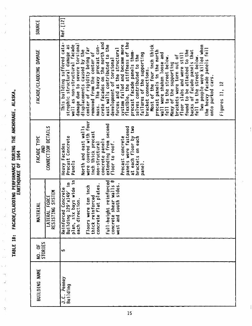
TABLE I Facade/Cladding Performance During Anchorage, Alaska 15 Earthquake of 1964
TABLE II Facade/Cladding Performance During San Fernando, 18 California Earthquake of 1971
TABLE III Facade/Cladding Performance During Miyagi-Ken-Oki, 19 Japan, Earthquake of 1978
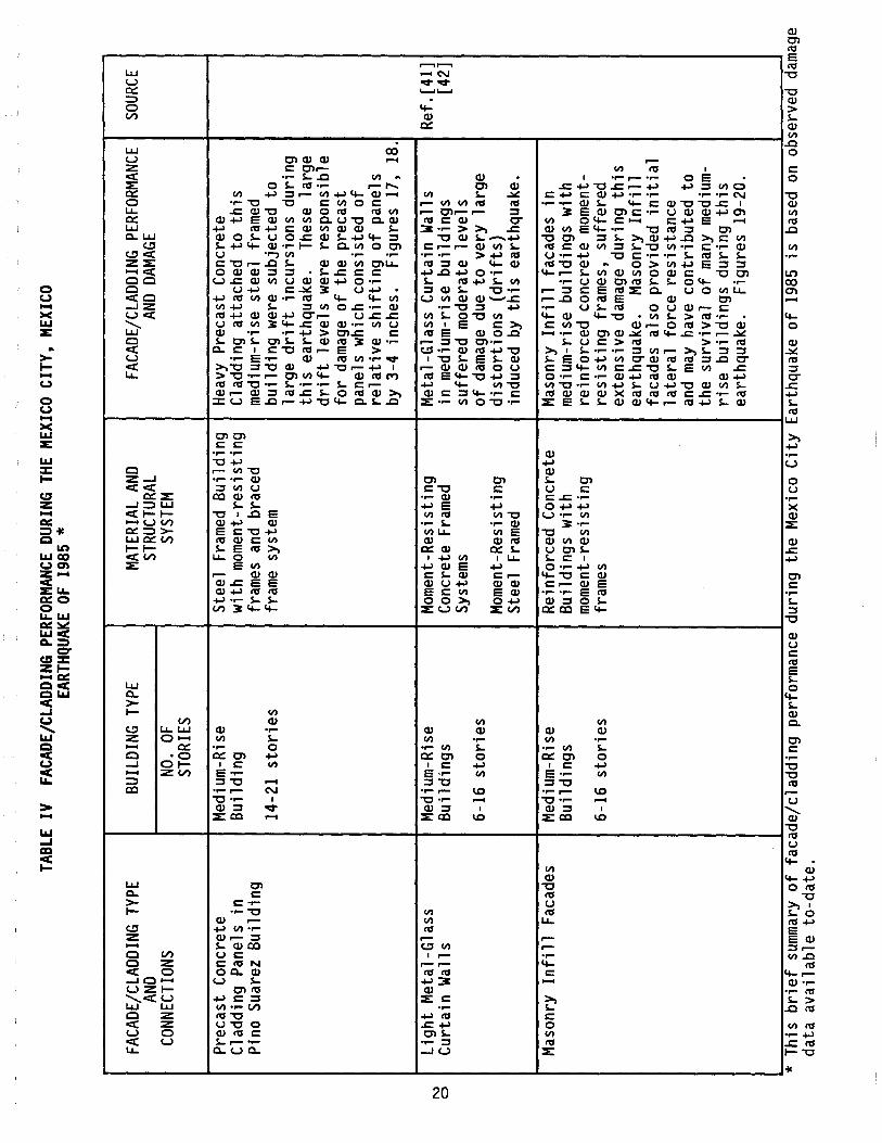
TABLE IV Facade/Cladding Performance During Mexico City, 20 Mexico, Earthquake of 1985
TABLE V Code Provisions for Seismic Design of Non-Structural 27 Facade/Cladding and Connections
TABLE VI TEST I - Summary of Test Results 44
TABLE VII TEST II - Summary of Cyclic Test Control Parameters 49
TABLE VIII TEST II - Summary of Test Results Threaded-Rod 51 Length = 6 Inches
TABLE IX TEST II - Summary of Test Results Threaded-Rod 52 Length = 8 Inches
TABLE X TEST III - Dynamic Test Runs and Test Parameters 57
TABLE XI TEST III-A - Summary of Test Results 58
TABLE XII TEST III-C - Summary of Test Results 59
TABLE XIII Analytical Evaluation of Results of Test III-A 69
LIST OF TABLES - APPENDIX B
TABLE I Summary of Peak Response Data - Test II Specimen 8-26 FPCRT-L6; Run AF @ 0.1 Hz
TABLE II Summary of Peak Response Data - Test II Specimen 8-27 FPCRT-L6; Run BF @ 0.5 Hz
TABLE III Summary of Peak Response Data - Test II Specimen 8-28 FPCRT-L8; Run A @ 0.1 Hz
TABLE IV Summary of Peak Response Data - Test II Specimen 8-29 FPCRT-L8; Run B @ 0.5 Hz
xi
CHAPTER 1: INTRODUCTION
This report documents results of a research program carried out to investigate the behavior of heavy facades/claddings and connections in buildings during earthquakes.
The widespread use of heavy facades and claddings in a broad class of buildings in seismic zones, and the potential life-hazards and significant economic losses posed by damage and/or collapse of such heavy exterior finish systems warrants a systematic and thorough examination of the behavior of heavy facades and claddings during earthquakes.
The overall nature and scope of the problem is further evidenced by available observed damage data on the behavior of exterior facade/cladding enclosure systems in buildings during previous earthquakes, e.g., Anchorage, Alaska-1964, San Fernando, California-1971, Miyagi-Ken-Oki, Japan-1978, Mexico City, Mexico-1985, and Whittier-Narrows, California-1987.
A study of the limited available observed damage data clearly shows that mitigation of earthquake damage of building facades/claddings is a very important issue because of the potential hazard to public and significant economic losses posed by such non-structural damage in buildings during earthquakes.
The importance of mitigation of earthquake damage of exterior architectural components, e.g., facades/claddings in buildings was also highlighted at the EERI/NSF workshop (40) on non-structural issues, to attempt to define practical research needs and further research work.
Furthermore, heavy facades and cladding can have significant influence on the overall lateral stiffness of buildings and thus alter the fundamental dynamic properties, e.g., natural frequencies, and also damping, and hence the response and behavior of the overall building system during earthquakes.
It is only recently that efforts have been directed to developing a better understanding of behavior of claddings and connections during earthquakes.
The general lack of an adequate base of test data on the static and cyclic behavior of building facades/claddings and connections, necessitates that testing be carried out to provide quantitative results on the strength and cyclic behavior of typical building facades/claddings and connections, including threshholds of damage, as well as their fundamental characteristics, e.g., natural frequencies, damping, etc.
It is also necessary to document and evaluate the effectiveness of the applicable design provisions of the regulatory standards, e.g., Uniform Building Code (86), ATC 3-06 (7), SEAOC (133), State of California (101), Tri-Services Manual (139) and the recently developed NEHRP Guidelines (28), through correlation with test results and available field data.
1 Numbers in parenthesis refer to Bibliography on page 71.
1
CHAPTER 2: BUILDING FACADES/CLADDINGS
2 • 1 BACKGROUND
In general, facades/claddings are regarded as a means of enclosing a building structure by attachment of enclosure material assemblies, capable of spanning between supporting points, on the exterior face of a building. The sizes of the cladding components are based in most part on their ability to resist lateral loads (e.g., wind and earthquakes) acting on the building, and then transfer those loads safely to the building:
The function of building facades/claddings may be described as follows, to provide:
a. Building envelope that protects the interior of the building from all climatic conditions and maintain a comfortable thermal environment.
b. Acoustic insulation that protects the occupants from noise poll ution.
c. Fire resistance.
d. Solar protection and possibly reduce the energy demand of HVAC systems.
e. Enhancement to building's external appearance.
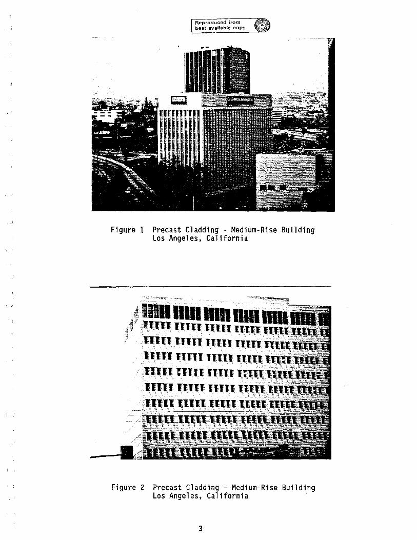
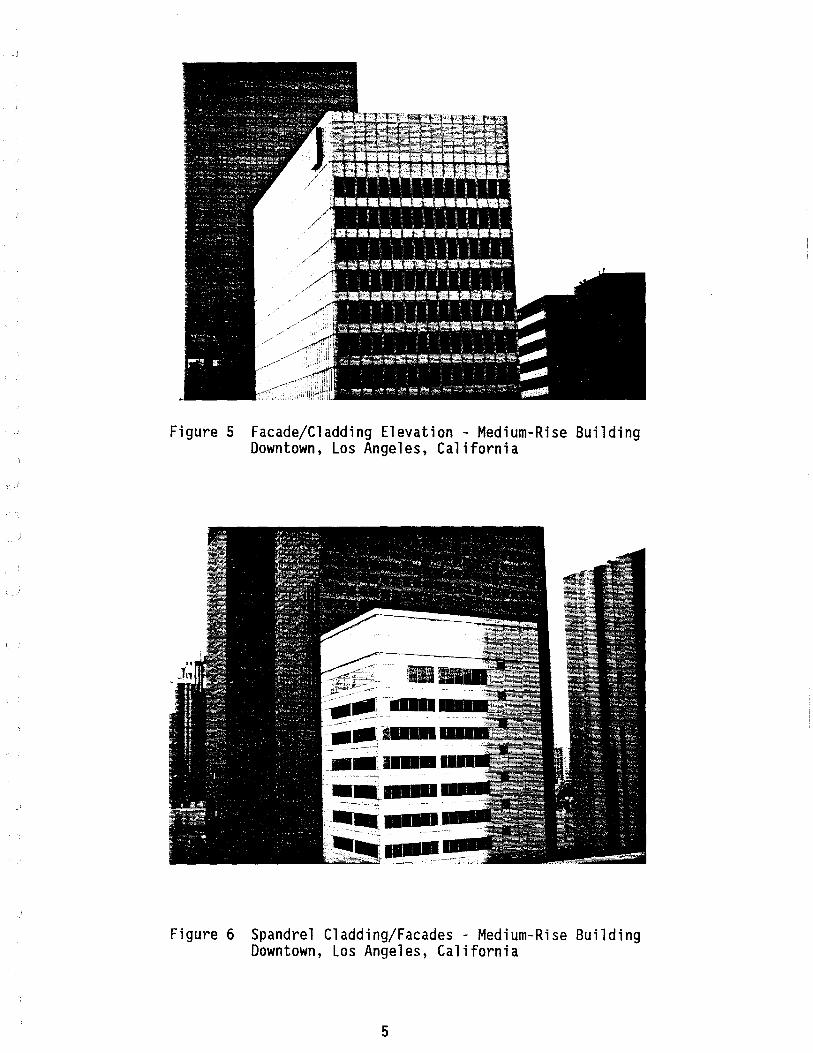
Photographs (Figures 1-9) show the many different facade/cladding types, their configurations, materials and exterior finishes in use in low- and medium-rise buildings on the West Coast.
2
Reproduced from best available copy.
Figure 1 Precast Cladding - Medium-Rise Building Los Angeles, California
·111111111111111 11111 ..... 11rE·
~lllll11TII "1111.1111 ~lllll ~llIl Illll!!111 ____ .
~ -- -- '- - -;=- -7 -i =<; t--
Figure 2
1111111111 11111111n ___ _
Precast Cladding - Medium-Rise Building Los Angeles, California
3
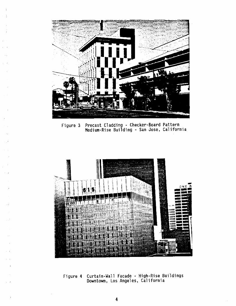
Figure 3 Precast Cladding - Checker-Board Pattern Medium-Rise Building - San Jose, California
Figure 4 Curtain-Wall Facade - High-Rise Buildings Downtown, Los Angeles, California
4
-I
Figure 5 Facade/Cladding Elevation - Medium-Rise Building Downtown, Los Angeles, California
----.--11. _I._ ~------.--_ .. _ ... . --...... ---- ---~-~ ---.--. ---------,.-
Figure 6 Spandrel Cladding/Facades - Medium-Rise Building Downtown, Los Angeles, California
5

Figure 7 Precast Cladding (Window-Wall Units) - Medium-Rise Building Downtown, Los Angeles, California
6
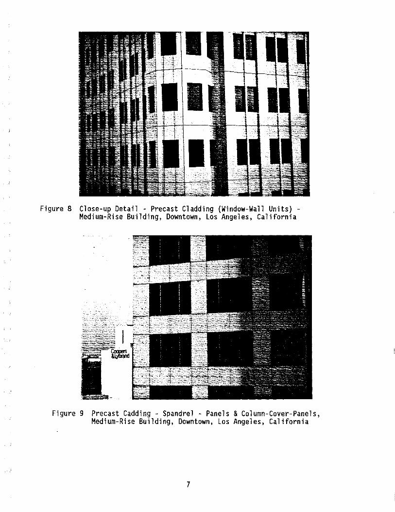
Figure 8 Close-up Detail - Precast Cladding (Window-Wall Units) -Medium-Rise Building, Downtown, Los Angeles, California
Figure 9 Precast Cadding - Spandrel - Panels & Column-Cover-Panels, Medium-Rise Building, Downtown, Los Angeles, California
7
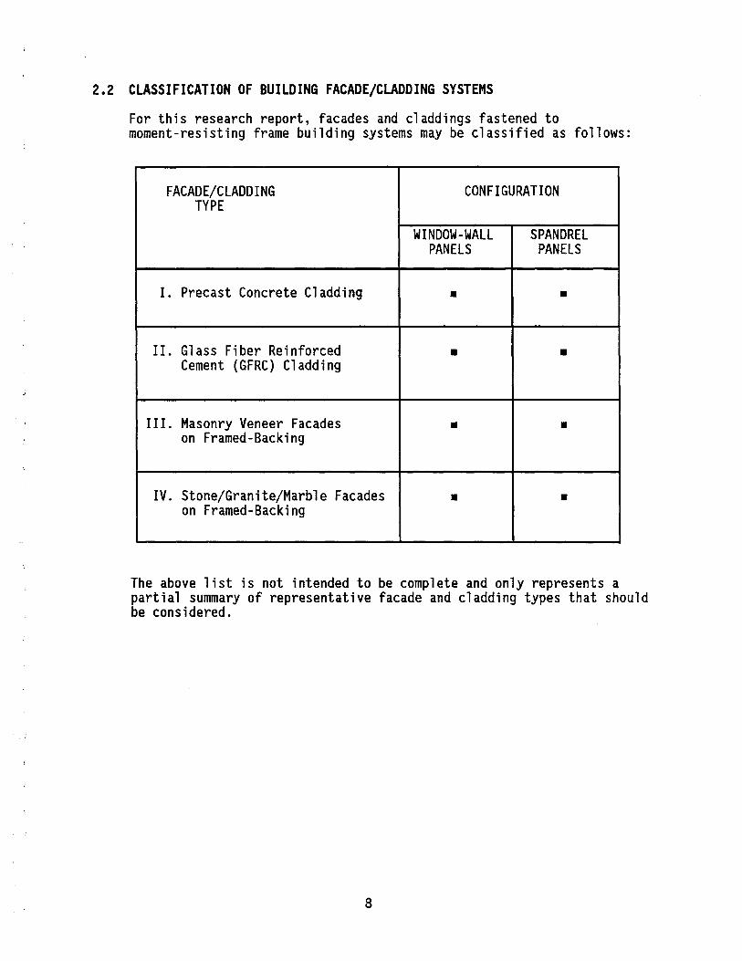
2.2 CLASSIFICATION OF BUILDING FACADE/CLADDING SYSTEMS
For this research report, facades and claddings fastened to moment-resisting frame building systems may be classified as follows:
FACADE/CLADDING CONFIGURATION TYPE
WINDOW-WALL SPANDREL PANELS PANELS
I. Precast Concrete Cladding • •
II. Glass Fiber Reinforced • • Cement (GFRC) Cladding
III. Masonry Veneer Facades • • on Framed-Backing
IV. Stone/Granite/Marble Facades • • on Framed-Backing
The above list is not intended to be complete and only represents a partial summary of representative facade and cladding types that should be considered.
8
2.3 DESIGN ISSUES
Development of facade/cladding systems in buildings in seismic zones requires the consideration of the following design issues:
o Facade/Cladding Component Issues
Under this category the following should be considered:
(i) Materials
From the point of view of earthquake resistance of facades/claddings, the following material issues should be considered in addition to the general considerations of appearance, durability and weather-staining:
- Mass Properties
- Strength and Deformation Properties
(ii) Geometry and Configuration
Important issues under this category are:
- Shape and Proportions of precast facade/cladding components, e.g., solid shapes, open vs. closed shapes and their combination thereof to provide desired facade/cladding elevations.
- Size of precast facade/cladding components, e.g., length, width, thickness, etc.
o Connections - Design Issues
Important connection design issues are:
- Types of connections with respect to number, types and methods of load transfer or accommodation of movement/deformation.
- Location of connections.
- Connections between precast facade/cladding components and supporting structural system.
- Connections between precast facade/cladding components.
o Supporting Structural System - Design Issues
The important issues under this category may be summarized as follows:
Gravity Loads - Supporting structural system must safely carry the weights of the precast facade/cladding components in addition to
9
usual dead and live loads, through the connections between the precast facade/cladding components and the supporting structure.
Lateral Loads (Wind, Earthquakes) - Supporting structural system must safely resist the effects of lateral loads, e.g., wind and earthquake loading, transmitted through the connections between the facade/cladding components and the supporting structure.
The interrelationship of the above design issues is graphically illustrated in Figure 10.
10
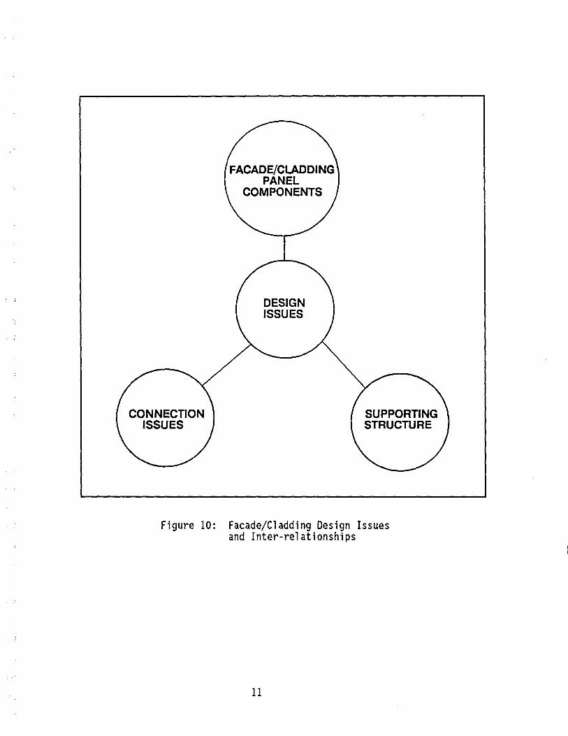
FACADE/CLADDING PANEL
COMPONENTS
DESIGN ISSUES
Figure 10: Facade/Cladding Design Issues and Inter-relationships
11
CHAPTER 3: SCOPE AND OBJECTIVES
The main focus of this research program is to analytically and experimentally investigate the seismic behavior and design of heavy facades/claddings and their connections in low/medium-rise buildings.
The general objective of this research program is to document and evaluate applicable current provisions of the Uniform Building Code (86) and other regulatory standards, e.g., State of California Title 21 and Title 24 (101), ATC 3-06 (7), SEAOC (131), Tri-Services Manual (139), NEHRP Guidelines (28), and current practices governing the design, detailing and installation of heavy facades/claddings and their connections in low and medium-rise buildings with different framing systems.
In light of the diverse range of facade/cladding components and connections in use in low/medium rise buildings in seismic zones across the U.S., it was decided to focus on investigating the seismic behavior and design of the following exterior finish systems representative of practices in California and other western states.
I. Precast Concrete Cladding Panels Attached to Moment-Resisting Rigid Frame Building Systems
II. Brick Veneer/Granite/Marble Facades on Framed Backing Attached to Moment-Resisting Rigid Frame Building Systems
It should be noted that a significant percentage of exterior building facades/claddings in California, are of the types outlined above.
Upon further consideration it was further decided to focus attention only on the study of Precast Concrete Cladding Panels and their attachments to steel-framed building systems, at this time.
12
CHAPTER 4: UTERATURE REVIEW
A comprehensive survey of pertinent literature was conducted. The results of this survey are presented in the form of an extensive bibliography (p.71) which provides an exhaustive source of information on a broad range of issues governing behavior, analysis and design of heavy facades/claddings and connections in buildings in seismic zones.
McCue, et al. (93) reported the results of an 'Enclosure Wall - Case Study' as an application of the conceptualized behavior models developed to investigate interaction of building components during earthquakes.
Sack, et al. (118) reported the first detailed investigation of the seismic response of precast curtain-walls in high-rise buildings. This research involved both analytical modeling of precast curtain-wall panels and their connections; as well as testing of curtain-walls and their connections.
Goodno, et al. (66), (67), (68), (69), (102), reported results of investigations of seismic response of glass curtain-walls as well as precast concrete cladding; cladding-structure interaction, analytical modeling for investigating the stiffening effects of cladding on the seismic response of buildings, as well as testing of cladding connections to investigate their behavior.
Wang (147), (148) reported the results of large-scale testing of precast cladding attached to a Full-Scale Steel Test Frame carried out under a U.S.-Japan Cooperative Research Project.
13
CHAPTER 5: FACADE/CLADDING PERFORMANCE DURING PREVIOUS EARTHQUAKES
In the initial phases of this research project, sincere efforts were made to systematically document the available data on observed performance of non-structural facades/claddings in buildings during previous earthquakes.
The first attempt to systematically document non-structural damage during earthquakes was reported by Ayres, et al. (12) for documenting the non-structural building damage caused by the Anchorage, Alaska, earthquake of 1964. Even though this was an excellent start, no consistent coordinated efforts have since been made to document non-structural building damage in general and facade/cladding damage in particular, during earthquakes since then.
Selected highlights of building facade/cladding performance and damage during the previous earthquakes are presented below as follows:
Table I Tabl e II : Tabl e II I: Table IV :
Anchorage, Alaska, Earthquake of 1964 San Fernando, California, Earthquake of 1971 Miyagi-Ken-Oki, Japan, Earthquake of 1978 Mexico City, Mexico, Earthquake of 1985
14
I-'
U'1
-,"
I L_
BUIL
DING
NAM
E
J.C
. Pe
nney
B
uild
i ng
TABL
E IB
: FA
CADE
/CLA
DDIN
G PE
RFOR
MAN
CE D
URIN
G TH
E AN
CHOR
AGE,
ALAS
KA,
EART
HQUA
KE O
F 19
64
NO.
OF
MAT
ERIA
L FA
CADE
TYP
E FA
CADE
/CLA
DDIN
G DA
MAGE
ST
ORIE
S AN
D LA
TERA
L FO
RCE
CONN
ECTI
ON D
ETAI
LS
RESI
STIN
G SY
STEM
5 R
einf
orce
d C
oncr
ete
Hea
vy F
acad
es
Thi
s bu
ildi
ng s
uffe
red
cata
-B
uild
ing
129'
x149
' in
P
reca
st C
oncr
ete
stro
phic
str
uctu
ral
dam
age
as
plan
, si
x ba
ys w
ide
in
Pane
ls
wel
l as
no
n-st
ruct
ural
fa
cade
ea
ch d
irec
tion
. da
mag
e du
e to
sev
ere
tors
iona
l N
orth
and
eas
t w
alls
di
spla
cem
ents
cau
sed
by t
he
Floo
rs w
ere
ten
inch
w
ere
cove
red
with
fo
ur
cent
er o
f ri
gid
ity
bei
ng f
ar
thic
k re
info
rced
in
ch
thic
k pr
ecas
t re
mov
ed
from
the
cen
ter
of
conc
rete
fla
t pl
ates
. no
n-st
ruct
ural
m
ass.
The
heav
y pr
ecas
t co
n-co
ncre
te p
anel
s cr
ete
faca
des
on t
he n
orth
and
F
ull-
heig
ht r
einf
orce
d ex
tend
ing
from
sec
ond
east
wal
ls c
ontr
ibut
ed t
o th
e co
ncre
te s
hear
wal
ls @
fl
oor
to r
oof.
de
velo
pmen
t of
tor
sion
al
wes
t an
d so
uth
side
s.
forc
es a
nd a
s th
e st
ruct
ural
P
reca
st c
oncr
ete
syst
em f
aile
d an
d be
cam
e m
ore
pane
ls w
ere
fast
ened
fl
exib
le,
the
stif
fnes
s of
the
at
eac
h fl
oor
by t
wo
prec
ast
faca
de
pane
ls t
hem
-br
acke
ts o
n ea
ch
selv
es c
ontr
ibut
ed t
o th
e pa
nel.
fail
ures
of
the
supp
ortin
g br
acke
t co
nnec
tion
s.
Mos
t of
the
fou
r in
ch t
hick
pr
ecas
t pa
nels
in
the
nor
th
wal
l w
ere
shak
en
loos
e an
d fe
ll
to t
he s
tree
t be
low
. M
any
of t
he s
uppo
rtin
g br
acke
ts w
ere
torn
out
of
floo
r sl
abs
and
wer
e st
ill
foun
d to
be
atta
ched
to
the
back
s of
fac
ade
pane
ls t
hat
fell
to
the
str
eet
belo
w.
Two
peop
le w
ere
kill
ed w
hen
the
heav
y fa
cade
pa
nels
fel
l on
to p
arke
d ca
rs.
Figu
res
11,
12
SOUR
CE
Ref
.[12
]/ I I I I I I

I-'
0)
BUIL
DING
NAM
E
Fir
st F
eder
al
Savi
ngs
Bui
ldin
g
TABL
E IA
: FA
CADE
/CLA
DDIN
G PE
RFOR
MAN
CE D
URIN
G TH
E AN
CHOR
AGE,
ALAS
KA,
EART
HQUA
KE O
F 19
64
NO.
OF
MAT
ERIA
L FA
CADE
TYP
E FA
CADE
/CLA
DDIN
G PE
RFOR
MAN
CE
STOR
IES
AND
AND
DAMA
GE
LATE
RAL
FORC
E CO
NNEC
TION
DET
AILS
RE
SIST
ING
SYST
EM
3 St
eel-
Fram
ed O
ffic
e V
arie
ty o
f ex
teri
or
The
curt
ain
wal
ls s
uffe
red
Bui
ldin
g 50
'x13
0'
in
wal
l m
ater
ials
. on
ly m
inor
dam
age
duri
ng t
his
plan
. ea
rthq
uake
bec
ause
of
Gla
ss-S
pand
rel
curt
ain
com
pati
bili
ty b
etw
een
the
Floo
rs a
re 3
-1/2
inc
h w
alls
-
Eas
t, So
uth
&
flex
ible
cur
tain
wal
l an
d co
ncre
te s
labs
po
rtio
n of
Wes
t th
e fl
exib
le s
teel
fr
ame
of
supp
orte
d by
ste
el
faca
des.
th
e bu
ildi
ng.
beam
s. B
rick
fil
ler
pane
ls
One
bric
k pa
nel
on t
he e
ast
Lat
eral
fo
rce
resi
s-w
ith
stee
l x-
brac
ed
faca
de c
olla
psed
and
the
ta
nce
in t
he N
-S
fram
e ba
ckin
g ot
her
bric
k pa
nels
on
the
dire
ctio
n (l
ong
east
and
sou
th s
ides
wer
e di
rect
ion)
su
ppos
ed
Ref
.[12
] pr
esen
ts
seve
rely
dam
aged
. to
be
prov
ided
by
a ex
act
det
ails
of
rein
forc
ed b
lock
th
e cu
rtai
n w
all
Rig
id n
on-s
truc
tura
l fa
cade
wa
11
in t
he w
est
and
its
conn
ectio
n w
ere
not
com
patib
le w
ith
the
face
and
tw
o br
ick
to t
he s
teel
fr
ame.
fl
exib
le s
truc
tura
l fr
ame
and
pane
ls i
n th
e ea
st
ther
efor
e th
e ri
gid
faca
de
face
. su
ffer
ed e
xten
sive
dam
age.
Lat
eral
fo
rce
resi
s-Th
e pa
nel
on t
he s
outh
fac
ade
tanc
e in
the
eas
t-co
uld
not
cope
with
the
w
est
dire
ctio
n m
ovem
ents
of t
he s
teel
fr
ame,
(n
arro
w d
irec
tion
) an
d w
as s
ever
ely
dam
aged
. pr
ovid
ed b
y a
rein
-fo
rced
bl
ock
wal
l Fi
gur
es 1
3,
14
at t
he n
orth
end
and
a
bric
k pa
nel
and
an
x-br
aced
ste
el
bent
in
the
sou
th
face
.
--------
i-.-~~~
~----.----~
SOUR
CE
Ref
. [12
]

SUMMARY OF BUILDING FACADE DAMAGE - ANCHORAGE, ALASKA EARTHQUAKE OF 1964 [Source Ref. 12]
111. Heavy precast-concrete panels that were attached to the buil di ng frame by clip angles and inserts collapsed.
2. Concrete-masonry-units filler walls were badly cracked and in some instances they damaged the surrounding structural frame.
3. Brick veneers, attached to flexible steel frames without backing or with insufficient backing, cracked and in some instances collapsed. Some stone and brick veneers collapsed where they were imporperly tied to concrete walls
4. Curtain Walls sustained very little damage, except in the vicinity of structural failures. Some mounting brackets broke or pulled loose their concrete inserts at the floor slabs.
5. Glass-block panels were practically undamaged.
6. Window-glass was damaged where adjacent structural elements failed or sustained excessive deflections. Where mounts were rigid and mullions were weak, large panels of glass in storefronts were broken. Some glass panels in curtain walls were damaged when flexible mountings worked 100se. 1I
-17-

I-'
ex>
BUIL
DING
NAM
E
Oliv
e V
iew
Hos
pita
l
Med
ical
T
reat
men
t an
d C
are
Uni
t
TABL
E II
FA
CADE
/CLA
DDIN
G PE
RFOR
MAN
CE D
URIN
G TH
E SA
N FE
RNAN
DO,
CALI
FORN
IA
EART
HQUA
KE O
F 19
71
[REF
. 13
9]
NO.
OF
MAT
ERIA
L FA
CADE
TYP
E FA
CADE
/CLA
DDIN
G PE
RFOR
MAN
CE
STOR
IES
AND
AND
DAMA
GE
LATE
RAL
FORC
E CO
NNEC
TION
DET
AILS
RE
SIST
ING
SYST
EM
5 R
einf
orce
d C
oncr
ete
Pre
cast
Con
cret
e M
any
prec
ast
conc
rete
fac
ia
Faci
a E
lem
ents
el
emen
ts w
ere
disl
odge
d.
Bas
ic F
ram
ing
sche
me
is a
tw
o-w
ay f
lat
Mas
onry
ven
eere
d sl
ab r
einf
orce
d w
all
Mas
onry
ven
eere
d w
alls
fel
l co
ncre
te s
yste
m
away
fro
m t
he b
uild
ing
due
supp
orte
d ei
ther
on
to e
arth
quak
e m
ovem
ents.
ti
ed o
r sp
iral
co
lum
ns.
Con
nect
ions
an
chor
ing
the
The
late
ral
forc
e co
ncre
te f
aile
d.
resi
stin
g sy
stem
co
nsis
ts o
f a
syst
em
Figu
re 1
5 of
she
ar w
alls
abo
ve
the
seco
nd f
loor
and
m
omen
t re
sist
ing
fram
es
in
the
low
er
two
sto
ries
.
SOUR
CE
Ref
. [1
40)

I-'
U)
BUIL
DING
NAM
E
Sasa
ki
Bui
ldin
g Iz
umi
Cit
y,
Japa
n
TABL
E II
I FA
CADE
/CLA
DDIN
G PE
RFOR
MAN
CE D
URIN
G TH
E M
IYAG
I-KEN
-OKI
, JA
PAN,
EA
RTHQ
UAKE
OF
1978
[RE
F.
39]
NO.
OF
MAT
ERIA
L FA
CADE
TYP
E FA
CADE
/CLA
DDIN
G PE
RFOR
MAN
CE
STOR
IES
AND
AND
DAMA
GE
LATE
RAL
FORC
E CO
NNEC
TION
DET
AILS
RE
SIST
ING
SYST
EM
4 St
eel
Fram
ed B
uild
ing
Pre
cast
Con
cret
e C
atas
trop
hic
coll
apse
of
Cur
tain
Wal
ls
prec
ast
conc
rete
cur
tain
w
all s
. Th
e pr
ecas
t co
ncre
te
clad
ding
pan
els
brok
e lo
ose
from
the
bui
ldin
g ex
teri
or
and
fell
cr
ashi
ng t
o th
e gr
ound
bel
ow o
nto
park
ed
cars
.
Figu
re 1
6
SOUR
CE
Ref
. [3
9]
N o
FACA
DE/C
LADD
ING
TYPE
AN
D CO
NNEC
TION
S
Pre
cast
Con
cret
e C
ladd
ing
Pane
ls
in
Pino
Sua
rez
Bui
ldin
g
Lig
ht M
etal
-Gla
ss
Cur
tai n
Wal
ls
TABL
E IV
FA
CADE
/CLA
DDIN
G PE
RFOR
MAN
CE D
URIN
G TH
E M
EXIC
O CI
TY,
MEX
ICO
EART
HQUA
KE O
F 19
85 *
BUIL
DING
TYP
E M
ATER
IAL
AND
FACA
DE/C
LADD
ING
PERF
ORM
ANCE
ST
RUCT
URAL
AN
D DA
MAGE
NO
. OF
SY
STEM
ST
ORIE
S
Med
ium
-Rise
St
eel
Fram
ed B
uild
ing
Hea
vy P
reca
st C
oncr
ete
Bui
ldin
g w
ith m
omen
t-re
sist
ing
Cla
ddin
g at
tach
ed t
o th
is
fram
es
and
brac
ed
med
ium
-ris
e st
eel
fram
ed
14-2
1 st
orie
s fra
me
syst
em
buil
ding
wer
e su
bjec
ted
to
larg
e d
rift
inc
ursi
ons
duri
ng
this
ear
thqu
ake.
Th
ese
larg
e d
rift
lev
els
wer
e re
spon
sibl
e fo
r da
mag
e of
the
pre
cast
pa
nels
whi
ch c
onsi
sted
of
rela
tive
shi
ftin
g of
pan
els
by 3
-4
inch
es.
Figu
res
17,
18.
Med
ium
-Rise
M
omen
t-Res
istin
g M
etal
-Gla
ss C
urta
in W
alls
B
uild
ings
C
oncr
ete
Fram
ed
in m
ediu
m-r
ise
buil
ding
s Sy
stem
s su
ffer
ed m
oder
ate
leve
ls
6-16
sto
ries
of
dam
age
due
to v
ery
larg
e M
omen
t-Res
istin
g di
stor
tion
s (d
rift
s)
Stee
l Fr
amed
in
duce
d by
th
is e
arth
quak
e.
Mas
onry
In
fill
Fa
cade
s M
ediu
m-R
ise
Rei
nfor
ced
Con
cret
e M
ason
ry
Infi
ll
faca
des
in
Bui
ldin
gs
Bui
ldin
gs w
ith
med
ium
-ris
e bu
ildi
ngs
with
m
omen
t-re
sist
ing
rein
forc
ed c
oncr
ete
mom
ent-
6-16
sto
ries
fr
ames
re
sist
ing
fram
es,
suff
ered
ex
tens
ive
dam
age
duri
ng t
his
ea
rthq
uake
. M
ason
ry
Infi
ll
faca
des
also
pro
vide
d in
itia
l la
tera
l fo
rce
resi
stan
ce
and
may
hav
e co
ntri
bute
d to
th
e su
rviv
al
of m
any
med
ium
-ri
se b
uild
ings
dur
ing
this
ea
rthq
uake
. Fi
gure
s 19
-20.
L-_
__
__
__
__
__
.. _
__
__
__
__
__
__
__
__
__
.~_. _
__
----------
----
----
---_
.-----------
--_
.. --
--
-_
... ---
--_
.. _
--------
SOUR
CE
Ref
.[41
] [4
2]
* T
his
bri
ef s
umm
ary
of f
acad
e/cl
addi
ng p
erfo
rman
ce d
urin
g th
e M
exic
o C
ity
Ear
thqu
ake
of 1
985
is b
ased
on
obse
rved
dam
age
data
ava
ilab
le t
o-da
te.

~_I
Figure 11 Collapsed Precast Concrete Facade Panels J. C. Penney Building Anchorage, Alaska Earthquake of 1964 (Ref.12)
Figure 12 Collapsed Precast Concrete Facade Panels J. C. Penney Building Anchorage, Alaska Earthquake of 1964 (Ref.12)
21
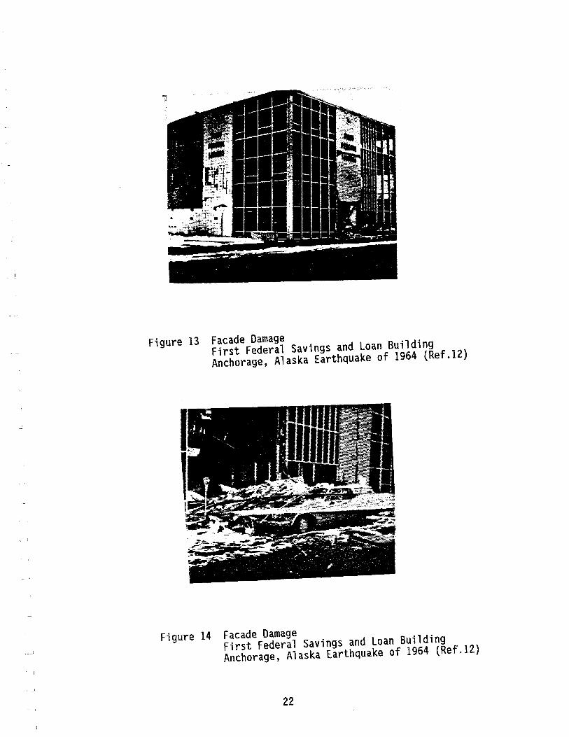
Figure 13 Facade Damage First Federal Savings and Loan Building Anchorage, Alaska Earthquake of 1964 (Ref.12)
Figure 14 Facade Damage First Federal Savings and Loan Building Anchorage, Alaska Earthquake of 1964 (Ref.I2)
22
-~
_i
Figure 15 Failure of Precast Concrete Wall Panels San Fernando, California Earthquake; 1971 (Ref.139)
Figure 16 Collapse of Precast Concrete Curtain Walls Miyagi-Ken-Oki, Japan Earthquake, 1978 (Ref.39)
23
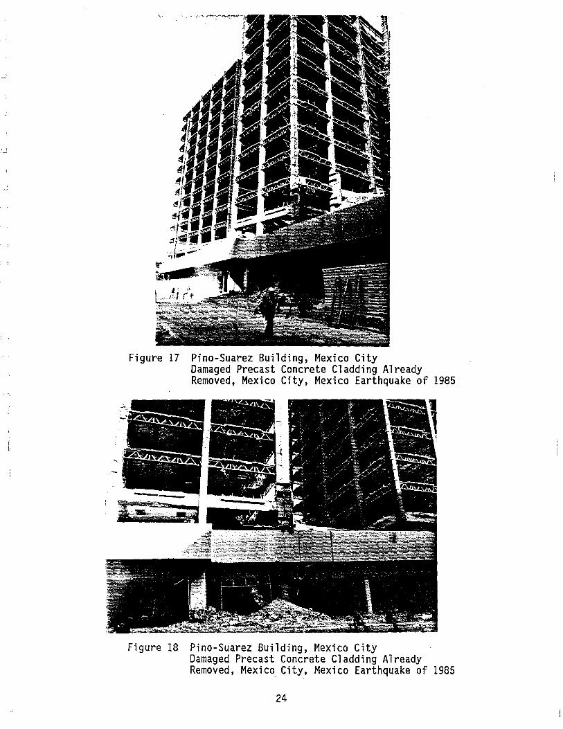
Figure 17 Pino-Suarez Building, Mexico City Damaged Precast Concrete Cladding Already Removed, Mexico City, Mexico Earthquake of 1985
L~\... -- s~-
f
~ - ./
Figure 18 Pino-Suarez Building, Mexico City Damaged Precast Concrete Cladding Already Removed, Mexico City, Mexico Earthquake of 1985
24
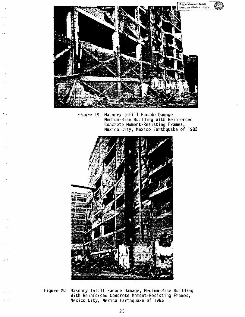
Figure 19 Masonry Infill Facade Damage Medium-Rise Building With Reinforced Concrete Moment-Resisting Frames, Mexico City, Mexico Earthquake of 1985
Figure 20 Masonry Infill Facade Damage, Medium-Rise Building With Reinforced Concrete Moment-Resisting Frames, Mexico City, Mexico Earthquake of 1985
25
CHAPTER 6: SEISMIC DESIGN CODES AND REGULATIONS
The provisions of the following codes and regulatory standards governing the seismic design and detailing of facades/claddings and their connections were reviewed:
• ATC 03-6
• USC
• Tri-Services Manual
• SEAOC
• OSA - State of California
• NEHRP
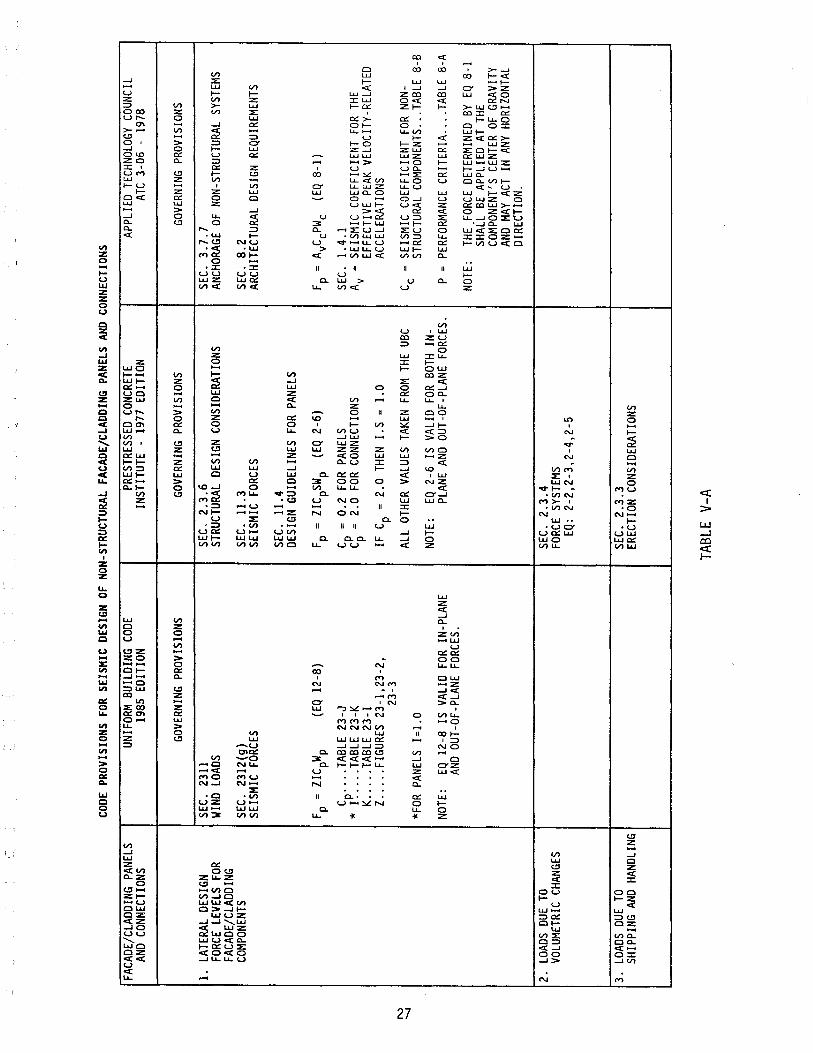
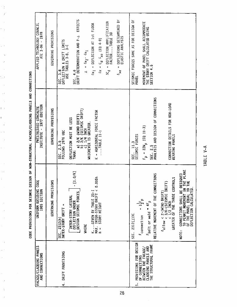
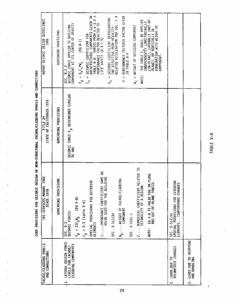
A summary of the applicable code provisions is presented in Tables V-A and V-S.
26
N
'-J
FACA
DE/C
LADD
ING
PANE
LS
AND
CONN
ECTI
ONS
1.
LATE
RAL
DESI
GN
FORC
E LE
VELS
FO
R FA
CADE
/CLA
DDIN
G CO
MPON
ENTS
2.
LOAD
S DU
E TO
VO
LUM
ETRI
C CH
ANGE
S
3.
LOAD
S DU
E TO
SH
IPPI
NG A
ND H
ANDL
ING
CODE
PRO
VISI
ONS
FOR
SEIS
MIC
DES
IGN
OF N
ON-S
TRUC
TURA
L FA
CADE
/CLA
DDIN
G PA
NELS
AND
CON
NECT
IONS
UNIFO
RM B
UILD
ING
CODE
19
85 E
DITI
ON
GOVE
RNIN
G PR
OVIS
IONS
SEC.
23
11
WIN
D LO
ADS
SEC.
23
12(g
) SE
ISM
IC F
ORCE
S
Fp =
ZIC
pWp
(EQ
12-8
)
Cp ...
. TAB
LE 2
3-J
* I .
....
TABL
E 23
-K
K ....
. TAB
LE 2
3-1
Z ..
... F
IGUR
ES 2
3-1,
23-2
, 23
-3
*FOR
PAN
ELS
1=1.
0
NOTE
: EQ
12-
8 IS
VAL
ID F
OR I
N-PL
ANE
AND
OUT-
OF-P
LANE
FOR
CES.
PRES
TRES
SED
CONC
RETE
IN
STIT
UTE
-19
77 E
DITI
ON
GOVE
RNIN
G PR
OVIS
IONS
SEC.
2.
3.6
STRU
CTUR
AL D
ESIG
N CO
NSID
ERAT
IONS
SEC.
11
.3
SEIS
MIC
FOR
CES
SEC.
11
.4
DESI
GN G
UIDE
LINE
S FO
R PA
NELS
Fp =
ZIC
pSW
p (E
Q 2-
6)
C
= 0
.2
FOR
PANE
LS
C~ =
2.0
FOR
CON
NECT
IONS
IF C
p =
2.0
THE
N I.
S =
1.0
ALL
OTHE
R VA
LUES
TAK
EN F
ROM
THE
UBC
NOTE
: EQ
2-6
IS
VAL
ID F
OR B
OTH
IN-
PLAN
E AN
D OU
T-OF
-PLA
NE F
ORCE
S.
SEC.
2.
3.4
FORC
E SY
STEM
S EQ
: 2-
2,2-
3,2-
4,2-
5
SEC.
2.
3.3
EREC
TION
CON
SIDE
RATI
ONS
TABL
E V-
A
APPL
IED
TECH
NOLO
GY C
OUNC
IL
ATC
3-06
-19
78
GOVE
RNIN
G PR
OVIS
IONS
SEC.
3.
7.7
ANCH
ORAG
E OF
NON
-STRU
CTUR
AL S
YSTE
MS
SEC.
8.
2 AR
CHIT
ECTU
RAL
DESI
GN R
EQUI
REM
ENTS
Fp =
AyC
CPW
C
(EQ
8-1)
SEC.
1.
4.1
A
= S
EISM
IC C
OEFF
ICIE
NT F
OR T
HE
y EF
FECT
IVE
PEAK
VEL
OCIT
Y-RE
LATE
D AC
CELE
RATI
ONS
C
= S
EISM
IC C
OEFF
ICIE
NT F
OR N
ON-
e ST
RUCT
URAL
COM
PONE
NTS .
.. TA
BLE
8-B
P =
PER
FORM
ANCE
CRI
TERI
A ..
.. TA
BLE
8-A
NOTE
: TH
E FO
RCE
DETE
RMIN
ED B
Y EQ
8-1
SH
ALL
BE A
PPLI
ED A
T TH
E CO
MPO
NENT
'S CE
NTER
OF
GRAV
ITY
AND
MAY
ACT
IN A
NY H
ORIZ
ONTA
L DI
RECT
ION.
N
00
FACA
DE/C
LADD
ING
PANE
LS
AND
CONN
ECTI
ONS
4.
DRIF
T PR
OVIS
IONS
5.
PROV
ISIO
NS F
OR D
ESIG
N OF
CON
NECT
IONS
BE
TWEE
N TH
E FA
CADE
/ CL
ADDI
NG P
ANEL
S AN
D TH
E ST
RUCT
URAL
FRA
ME
CODE
PRO
VISI
ONS
FOR
SEIS
MIC
DES
IGN
OF N
ON-S
TRUC
TURA
L FA
CADE
/CLA
DDIN
G PA
NELS
AND
CON
NECT
IONS
UNIFO
RM B
UILD
ING
CODE
19
85 E
DITI
ON
GOVE
RNIN
G PR
OVIS
IONS
SEC.
23
12(h
) IN
TER-
STOR
Y DR
IFT
;
[
INTE
R-ST
ORY
LATE
RAL
] DE
FLEC
TION
UND
ER
• [I
.O/K
] DE
SIGN
SEI
SMIC
FOR
CES
WHE
RE
K ....
GIV
EN B
Y TA
BLE
23-1
MA
X.
INTE
R-ST
ORY
DRIF
T <
O.O
OSh
h;
STOR
Y HE
IGHT
SEC.
23
12(j)
3C
Fcon
nect
ion
I =
13
F p
F bol
t or
wel
d;
4Fp
RELA
TIVE
MOV
EMEN
T OF
THE
CON
NECT
IONS
A
< 2
'(WIN
D D
RIFT
) al
low
< 3
/K'(S
EISM
IC D
RIFT
) <
1/2
IN
CH
GREA
TER
OF T
HE T
HREE
CON
TROL
S
NOTE
: CO
NNEC
TION
S SH
ALL
BE D
ESIG
NED
TO P
ERM
IT M
OVEM
ENT
IN T
HE P
LANE
OF
THE
PAN
EL E
QUAL
TO
THE
DEFL
ECTI
ON C
ALCU
LATE
D.
PRES
TRES
SED
CONC
RETE
IN
STIT
UTE
-19
77 E
DITI
ON
GOVE
RNIN
G PR
OVIS
IONS
SEC.
2.
3.6
FOLL
OWS
1976
UBC
DEFL
ECTI
ON M
UST
BE L
ESS
THAN
: a)
2/
K (
WIN
D DR
IFT)
b)
3/
K (
SEIS
MIC
DRI
FT)
c)
1/4
INCH
W
HICH
EVER
IS
GRE
ATER
.
K =
HORI
ZONT
AL F
ORCE
FAC
TOR
....
TABL
E II
-I
SEC.
11
.3
SEIS
MIC
FOR
CES
Fp ;
2Z
Wp
(EQ
11-3
)
SEC.
2.
5 AN
ALYS
IS A
ND D
ESIG
N OF
CON
NECT
IONS
CONN
ECTI
ON D
ETAI
LS F
OR N
ON-L
OAD
BEAR
ING
PANE
LS
TABL
E V-
A
SEC.
3.
8 APPL
IED
TECH
NOLO
GY C
OUNC
IL
ATC
3-06
-19
78
GOVE
RNIN
G PR
OVIS
IONS
DEFL
ECTI
ON &
DRIF
T LI
MIT
S US
E TA
BLES
3-B
, 3-
C
SEC.
4.
6 DR
IFT
DETE
RMIN
ATIO
N AN
D P-
A EF
FECT
S
A
= o
X2-
oXl
oXl
= D
EFLE
CTIO
N AT
1st
FLO
OR
OX
=
Cd
axe
(EQ
4-9)
OCd
= D
EFLE
CTIO
N AM
PLIF
ICAT
ION
FACT
OR ..
.. TA
BLE
3B
0xe
=
DEFL
ECTI
ONS
DETE
RMIN
ED B
Y EL
ASTI
C AN
ALYS
IS
SEIS
MIC
FOR
CES
SAME
AS
FOR
DESI
GN O
F PA
NEL
MOVE
MENT
OF
PANE
L SH
ALL
ACCO
MMOD
ATE
THE
STOR
Y DR
IFT
CALC
ULAT
ED U
SING
SE
CTIO
N 4.
6
N ~
FACA
DE/C
LADD
ING
PANE
LS
AND
CONN
ECTI
ONS
1.
LATE
RAL
DESI
GN F
ORCE
LE
VELS
FOR
FAC
ADE/
CL
ADDI
NG C
OMPO
NENT
S
2.
LOAD
S DU
E TO
VO
LUME
TRIC
CHA
NGES
3.
LOAD
S DU
E TO
SHI
PPIN
G AN
D HA
NDLI
NG
---
------------
CODE
PRO
VISI
ONS
FOR
SEIS
MIC
DES
IGN
OF N
ON-S
TRUC
TURA
L FA
CADE
/CLA
DDIN
G PA
NELS
AND
CON
NECT
IONS
TRI-S
ERVI
CES
MANU
AL 1
982
TITL
E 24
NE
HRP
SEIS
MIC
DES
IGN
GUID
ELIN
ES
SEAO
C 19
78
STAT
E OF
CAL
IFOR
NIA
1979
19
85
GOVE
RNIN
G PR
OVIS
IONS
GO
VERN
ING
PROV
ISIO
NS
GOVE
RNIN
G PR
OVIS
IONS
SEC.
9-
3 SE
C.
8.2.
2 SE
ISM
IC F
ORCE
S SE
ISM
IC F
ORCE
Fp
DETE
RMIN
ED S
IMIL
AR
SEIS
MIC
FOR
CE A
PPLI
ED T
O BU
ILDI
NG
TO U
BC
COMP
ONEN
T AT
IT
S CE
NTER
OF
GRAV
ITY
F P =
ZIC
pWp
(EQ
3-8)
Fp
= A
vCeP
We
(EQ
8-1)
C p
= 0
.3
[tab
le 3
-4]
C
= S
EISM
IC C
OEFF
ICIE
NT F
OR
SPEC
IAL
PROV
ISIO
NS F
OR E
XTER
IOR
e AR
CHIT
ECTU
RAL
COMP
ONEN
TS G
IVEN
IN
EL
EMEN
TS
TABL
E 8-
8.
VARI
ES F
ROM
0.6-
3.0
x PE
RFOR
MANC
E FA
CTOR
REA
LTED
TO
I ...
.. IM
PORT
ANCE
COE
FFIC
IENT
SAM
E AS
LI
FE S
AFET
Y (0
.5-1
.5)
VALU
E US
ED F
OR T
HE B
UILD
ING
SEC.
3-
3(J)
3d
Av =
SEI
SMIC
COE
FFIC
IENT
REP
RESE
NTIN
G TH
E EF
FECT
IVE-
PEAK
-VEL
OCIT
Y-RE
LATE
D AC
CELE
RATI
ON P
ER S
EC.
1.4
Wp ...
.. W
EIGH
T OF
FA
CADE
/CLA
DDIN
G CO
MPON
ENT
P =
PER
FORM
ANCE
CRI
TERI
A FA
CTOR
GIV
EN
IN T
ABLE
8-A
SE
C.
3-3(
0)-1
Z ....
. NUM
ERIC
AL C
OEFF
ICIE
NT R
ELAT
ED T
O We
= W
EIGH
T OF
BUI
LDIN
G CO
MPON
ENT
SEIS
MIC
ITY
OF A
REG
ION.
NO
TE:
THE
FORC
E F
SHAL
L BE
APP
LIED
IN
DEPE
NDEN
Try
LONG
ITUD
INAL
LY
NOTE
: EQ
3-8
IS
VALI
D FO
R IN
-PLA
NE
(IN-P
LAN
E),
LATE
RALL
Y (O
UT-O
F-AN
D OU
T-OF
-PLA
NE F
ORCE
S. PL
ANE)
, OR
VER
TICA
LLY
IN
COM
BINA
TION
WITH
WEIG
HT O
F CO
MPON
ENT.
SEC.
3-
3(J)
3d
SPEC
IAL
PROV
ISIO
NS F
OR E
XTER
IOR
ELEM
ENTS
... T
EMPE
RATU
RE C
HANG
ES
! i
TABL
E V-
B

w
a
FACA
DE/C
LADD
ING
PANE
LS
AND
CONN
ECTI
ONS
4.
DRIF
T PR
OVIS
IONS
CODE
PRO
VISI
ONS
FOR
SEIS
MIC
DES
IGN
OF N
ON-ST
RUCT
URAL
FAC
ADE/
CLAD
DING
PAN
ELS
AND
CONN
ECTI
ONS
TRI-S
ERVI
CES
MANU
AL 1
982
SEAO
C 19
78
GOVE
RNIN
G PR
OVIS
IONS
SEC.
3-
31H
l IN
TER-
STOR
~ DR
IFT
=
DEFL
ECTI
ON U
NDER
.(
1.0/
K)
[IN
TER-
STOR
Y LA
TERA
L ]
DESI
GN S
EISM
IC F
ORCE
S
WHER
E 1.
0/K
> 1
.0
K =
NUM
ERIC
AL C
OEFF
ICIE
NT G
IVEN
BY
TABL
E 3-
3
MAX.
INTE
R-ST
ORY
DRIF
T ~
O.OO
Sh
h =
ST
ORY
HEIG
HT
TITL
E 24
ST
ATE
OF C
ALIF
ORNI
A 19
79
GOVE
RNIN
G PR
OVIS
IONS
MAX
INTE
RSTO
RY D
RIFT
~
O.OO
Sh
h =
STO
RY H
EIGH
T
MAX.
INTE
RSTO
RY D
RIFT
~
O.0
025h
'
hi
= H
EAD
TO S
ILL
OF G
LAZE
D OP
ENIN
GS
TABL
E V-
B
NEHR
P SE
ISM
IC D
ESIG
N GU
IDEL
INES
19
85
GOVE
RNIN
G PR
OVIS
IONS
SEC
3.8
DEFL
ECTI
ON A
ND D
RIFT
LIM
ITS
DES I
GN S
TORY
DRI
FT
£, <
ALL
OW.
STOR
Y
TABL
E 3-
C DR
IFT
£'a
ALLO
WAB
LE S
TORY
DRI
FT 6
a =
O.O
IO-O
.OI5
h sx
BASE
D ON
SEI
SMIC
HAZ
ARD
EXPO
SURE
GRO
UP
h sx
= S
TORY
HEI
GHT
SEC.
4-
6.1
STOR
Y DR
IFT
DETE
RMIN
ATIO
N
DESI
GN S
TORY
DRI
FT 6
= 0x
t-0x
b
WHER
E ex
t &
0xb
ARE
LAT
ERAL
DE
FLEC
TION
S·@ T
OP &
BOTT
OM O
F TH
E ST
ORY
UNDE
R CO
NSID
ERAT
ION
LATE
RAL
DEFL
ECTI
ON O
x =
Cdo
xe
Cd =
DEF
LECT
ION
AMPL
IFIC
ATIO
N FA
CTOR
GI
VEN
IN T
ABLE
3-B
° =
DEF
LECT
IONS
DET
ERMI
NED
BY A
N xe
EL
ASTI
C AN
ALYS
IS U
SING
SEIS
MIC
DE
SIGN
FOR
CES
GIVE
N IN
SEC
. 4.
3.
DESI
GN S
TORY
DRI
FT
SHAL
L BE
IN
CREA
SED
BY T
HE
INCR
EMEN
TAL
FACT
OR
FOR
P-~
EFFE
CTS
AS P
ER S
EC.
4.6.
2.
w
......
FACA
DE/C
LADD
ING
PANE
LS
AND
CONN
ECTI
ONS
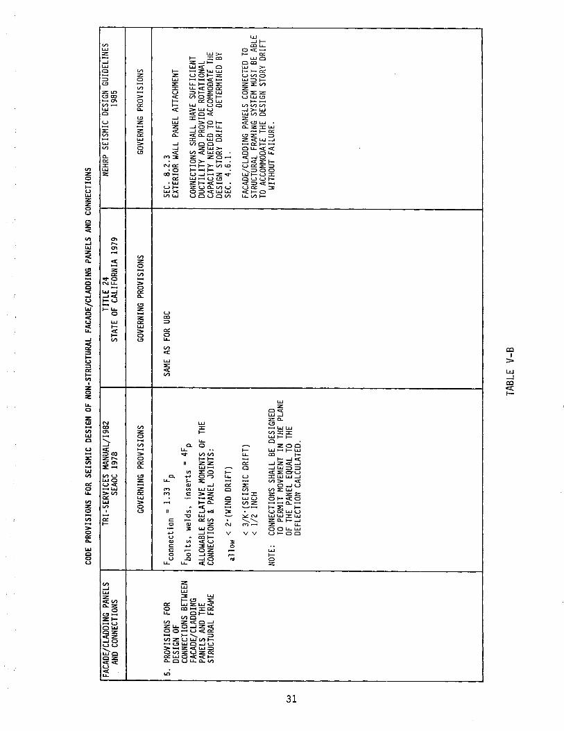
5.
PROV
ISIO
NS
FOR
DESI
GN O
F CO
NNEC
TION
S BE
TWEE
N FA
CADE
/CLA
DDIN
G PA
NELS
AND
THE
ST
RUCT
URAL
FRA
ME
--
... ~--
---
-
CODE
PRO
VISI
ONS
FOR
SEIS
MIC
DES
IGN
OF N
ON-S
TRUC
TURA
L FA
CADE
/CLA
DDIN
G PA
NELS
AND
CON
NECT
IONS
TRI-S
ERVI
CES
MAN
UAL/
1982
TI
TLE
24
NEHR
P SE
ISM
IC D
ESIG
N GU
IDEL
INES
SE
AOC
1978
ST
ATE
OF C
ALIF
ORNI
A 19
79
1985
GOVE
RNIN
G PR
OVIS
IONS
GO
VERN
ING
PROV
ISIO
NS
GOVE
RNIN
G PR
OVIS
IONS
Fcon
nect
ion
= 1
.33
Fp
SAME
AS
FOR
UBC
SEC.
8.
2.3
EXTE
RIOR
WAL
L PA
NEL
ATTA
CHME
NT
Fbol
ts,
wel
ds,
inse
rts
=
4Fp
CONN
ECTI
ONS
SHAL
L HA
VE S
UFFI
CIEN
T AL
LOW
ABLE
REL
ATIV
E MO
MENT
S OF
THE
DU
CTIL
ITY
AND
PROV
IDE
ROTA
TION
AL
CONN
ECTI
ONS
& PA
NEL
JOIN
TS:
CAPA
CITY
NEE
DED
TO A
CCOM
MODA
TE T
HE
DESI
GN S
TORY
DRI
FT
DETE
RMIN
ED B
Y al
low
< 2
·(WIN
D DR
IFT)
SE
C.
4.6.
1.
< 3
/K·(S
EISM
IC D
RIFT
) FA
CADE
/CLA
DDIN
G PA
NELS
CON
NECT
ED T
O <
1/2
IN
CH
STRU
CTUR
AL F
RAMI
NG S
YSTE
M MU
ST B
E AB
LE
TO A
CCOM
MODA
TE T
HE D
ESIG
N ST
ORY
DRIF
T NO
TE:
CONN
ECTI
ONS
SHAL
L BE
DES
IGNE
D W
ITHOU
T FA
ILUR
E.
TO P
ERM
IT M
OVEM
ENT
IN T
HE P
LANE
OF
THE
PAN
EL E
QUAL
TO
THE
DEFL
ECTI
ON C
ALCU
LATE
D.
,_ .. _
-------
----
----
---
_ ..
...
-----
---
----
---
--
-----
--
--------
-----~
-------
--
----
-_.-
-------
..
TABL
E V-
B
CHAPTER 7: REVIEW OF CURRENT DESIGN AND CONSTRUCTION PRACTICES
7.1 FACADES/CLADDING PANELS
7 • 2 CONNECTI ONS
A schematic block diagram of the overall design process governing the seismic design and detailing of non-structural facades/cladding components and connections in buildings is presented on p.
Basically, the current facade/cladding and connections design and detailing practices are based on the following:
• Seismic Design Codes and Regulations, e.g., UBC, ATC, Tri-Services Manual, SEAOC, OSA, NEHRP
Comparative evaluation of applicable seismic design codes was presented in Chapter 6 .
• Industry Standards and Guidelines
Guidelines for design, detailing, production, and erection of precast concrete facade/cladding panels and connections are provided by Prestressed Concrete Institute (106), (107), (108), (109), (110), (124), Precast Product Manufacturers (89) and others (103).
Current Facade/Cladding Construction Practices
GFRC Cladding Panels
This type of cladding is becoming increasingly popular on the West Coast. Figure 21 shows a GFRC cladding panel fabricted at a precasting plant before being shipped to the construction site.
Figure 22 shows a typical GFRC cladding panel being lifted for shipment at a precasting plant on the West Coast.
Precast Concrete Spandrel Panels
This type of facade/cladding is widely used not only on the West Coast but other states as well, in the United States.
Figures 23 and 24 show typical precast concrete spandrel panels being delivered to a construction site in the San Francisco Bay Area. The precast panels already have steel-angle-attachment assemblies embedded in them during the panel fabrication process.
Figure 25 shows typical layout and configuration of precast concrete spandral panels during construction in a low-rise steel-framed building near San Francisco.
Figure 26 shows close-up detail of precast concrete spandrel panels and column-cover-panels during construction.
32
Figure 27 shows the installation of precast column-cover-panels in progress in a low-rise steel-framed building near San Francisco.
Precast Concrete Window-Wall Cladding Panels
Figure 28 shows the installation and connection details of a storyhigh precast concrete cladding panel in a steel-framed high-rise buildings in San Francisco.
Figure 29 shows the detailing and installation of precast concrete cladding corner units in a steel-framed high-rise building in San Francisco.
Precast Concrete Facades/Claddings and Connections
In light of the diverse range of facade/cladding components and connections used in low/medium-rise buildings in seismic zones across the U.S., it was decided to focus on investigating the seismic behavior and design of precast concrete cladding panels attached to rigid-frame building structural systems representative of current practices in the U.S. It was further decided to focus on the investigation of seismic behavior and design of story-high window-wall panel components and connections in buildings with moment-resisting frame structural systems.
Connections
A study of the state-of-the-art of seismic design and detailing of cladding connections shows that there are many different types of connections and details in use in different parts of the U.S.
According to current design practice in California and other seismic zones of the U.S., Ref. (89), (93), (106), (53), (124), (125), (103), (108), (109), (110), (147), (148) connections of precast concrete window-wall facade/cladding panels to the building structural frames may be divided into the following categories:
• Flexible Connection at Top
Typically there are two attachment points at top of the cladding panel. These felxible or push-pull connections between the cladding panel and the structural frame are expected to accommodate all possible differential movements including inter-story drifts caused by lateral load, e.g., wind and earthquakes; as well as differential movements due to unbalanced gravity loads, temperature changes, creep and shrinkage .
• Bearing Connection at Bottom
Typically there are two attachment points at the bottom of the cladding panel. These rigid connections at the bottom of cladding panels are designed to provide resistance to gravity and lateral loads, e.g., wind and earthquakes.
33
In current design practice, it is assumed that cladding contributes only mass to building system. Thus the designer accounts for facade/cladding in the seismic design process by including only the dead weight of cladding panels tributary to building floor under consideration. The total mass distribution in the building, thus obtained is used along with the lateral stiffness of the building to determine fundamental dynamic properties, e.g., modal frequencies and mode shapes, as well as seismic response analysis and design of the building system.
It is also assumed that the flexible lateral connections at top of the cladding panels provide no in-plane earthquake resistance and function only to accommodate differential movements between the facade/cladding panels and building structural frames.
34
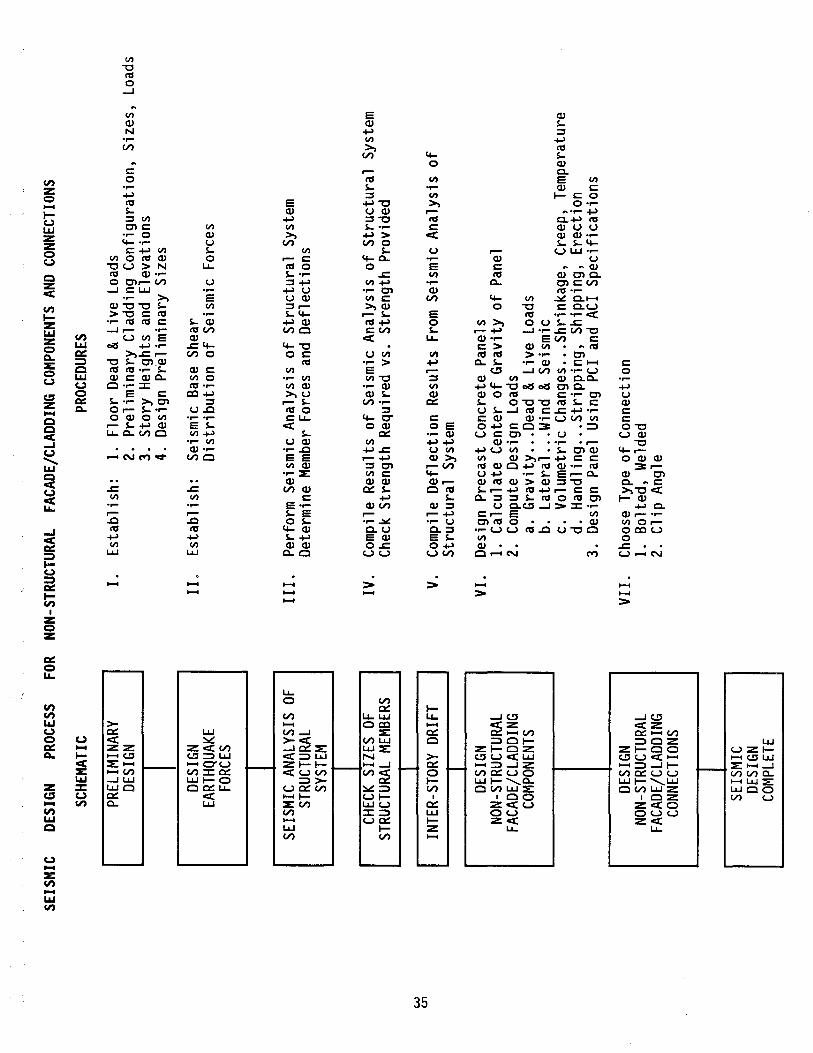
w
U"I
SEIS
MIC
DE
SIGN
PR
OCES
S FO
R NO
N-ST
RUCT
URAL
FA
CADE
/CLA
DDIN
G CO
MPO
NENT
S AN
D CO
NNEC
TION
S
SCHE
MAT
IC
PREL
IMIN
ARY
DESI
GN
DESI
GN
EART
HQUA
KE
FORC
ES
SEIS
MIC
ANA
LYSI
S OF
ST
RUCT
URAL
SY
STEM
CHEC
K SI
ZES
OF
STRU
CTUR
AL M
EMBE
RS
INTE
R-ST
ORY
DRIF
T
DESI
GN
NON-
STRU
CTUR
AL
FACA
DE/C
LADD
ING
COM
PONE
NTS
DESI
GN
NON-
STRU
CTUR
AL
FACA
DE/C
LADD
ING
CONN
ECTI
ONS
SEIS
MIC
DE
SIGN
CO
MPL
ETE
~--
------------
-------
PROC
EDUR
ES
I.
Est
abli
sh:
1.
Floo
r D
ead
& Li
ve
Load
s 2.
Pr
elim
inar
y C
ladd
ing
Con
figu
rati
on,
Siz
es,
Load
s 3.
St
ory
Hei
ghts
an
d E
leva
tions
4.
D
esig
n Pr
elim
inar
y Si
zes
II.
Est
abli
sh:
Seis
mic
Bas
e Sh
ear
Dis
trib
utio
n of
Sei
smic
For
ces
III.
Pe
rfor
m S
eism
ic A
naly
sis
of S
truc
tura
l Sy
stem
D
eter
min
e M
embe
r Fo
rces
an
d D
efle
ctio
ns
IV.
Com
pile
Res
ults
of
Seis
mic
Ana
lysi
s of
Str
uctu
ral
Syst
em
Chec
k St
reng
th R
equi
red
vs.
Str
engt
h Pr
ovid
ed
V.
Com
pile
Def
lect
ion
Res
ults
Fro
m S
eism
ic A
naly
sis
of
Str
uctu
ral
Syst
em
VI.
Des
ign
Pre
cast
Con
cret
e Pa
nels
1.
C
alcu
late
Cen
ter
of G
ravi
ty o
f Pa
nel
2.
Com
pute
Des
ign
Load
s a.
G
ravi
ty ..
. Dea
d &
Liv
e Lo
ads
b.
Lat
eral
...
Wind
& Se
ism
ic
c.
Vol
umet
ric C
hang
es ...
Shr
inka
ge,
Cre
ep,
Tem
pera
ture
d.
H
andl
ing
... S
trip
ping
, Sh
ippi
ng,
Ere
ctio
n 3.
D
esig
n Pa
nel
Usin
g PC
I an
d AC
I S
peci
fica
tion
s
VII
. C
hoos
e Ty
pe o
f C
onne
ctio
n 1.
B
olte
d,
Wel
ded
2.
Clip
Ang
le
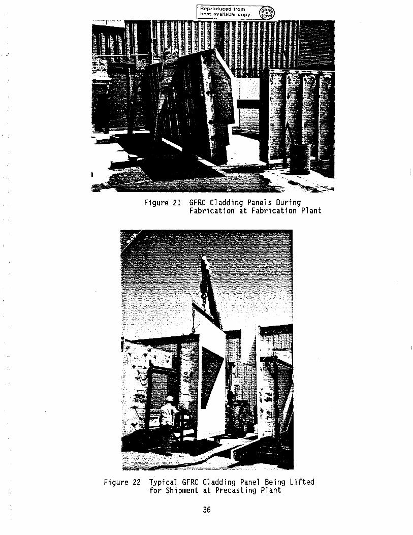
Figure 21 GFRC Cladding Panels During Fabrication at Fabrication Plant
Figure 22 Typical GFRC Cladding Panel Being Lifted for Shipment at Precasting Plant
36
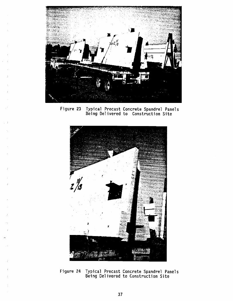
Figure 23 Typical Precast Concrete Spandrel Panels Being Delivered to Construction Site
Figure 24 Typical Precast Concrete Spandrel Panels Being Delivered to Construction Site
37
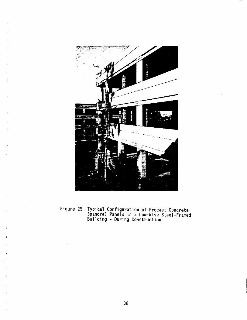
Figure 25 Typical Configuration of Precast Concrete Spandrel Panels in a Low-Rise Steel-Framed Building - During Construction
38

Figure 26 Close-up of Precast Concrete Spandrel Panels and Column-Caver-Panels - During Construction
39
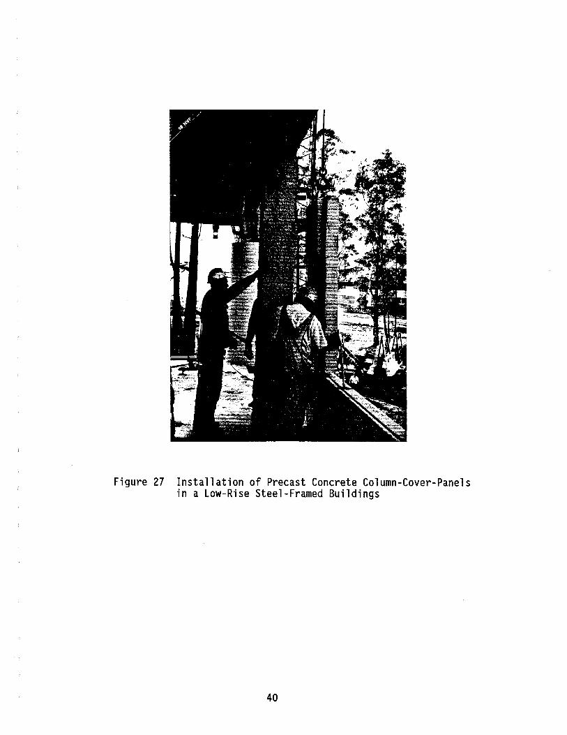
Figure 27 Installation of Precast Concrete Column-Caver-Panels in a Low-Rise Steel-Framed Buildings
40

Figure 28 Installation and Connection Details of a Story-High Precast Connection Cladding Panel in a Steel-Framed High-Rise Building
Figure 29 Installation and Details of Precast Concrete Cladding Corner Units in a Steel-Framed High-Rise Building
41
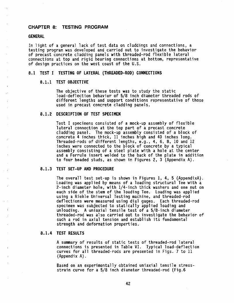
CHAPTER 8: TESTING PROGRAM
GENERAL
In light of a general lack of test data on c1addings and connections, a testing program was developed and carried out to investigate the behavior of precast concrete cladding panels with threaded-rod flexible lateral connections at top and rigid bearing connections at bottom, representative of design practices on the west coast of the U.S.
8.1 TEST I TESTING OF LATERAL (THREADED-ROD) CONNECTIONS
8.1.1 TEST OBJECTIVE
The objective of these tests was to study the static load-deflection behavior of 5/8 inch diameter threaded rods of different lengths and support conditions representative of those used in precast concrete cladding panels.
8.1.2 DESCRIPTION OF TEST SPECIMEN
Test I specimens consisted of a mock-up assembly of flexible lateral connection at the top part of a precast concrete cladding panel. The mock-up assembly consisted of a block of concrete 4 inches thick, 11 inches high and 40 inches long. Threaded-rods of different lengths, e.g., 4, 6, 8, 10 and 12 inches were connected to the block of concrete by a typical assembly conSisting of a steel plate with a hole at the center and a Ferrule insert welded to the back of the plate in addition to four headed studs, as shown in Figures 2, 3 (Appendix A).
8.1.3 TEST SET-UP AND PROCEDURE
The overall test set-up is shown in Figures 1, 4, 5 (AppendixA). Loading was applied by means of a loading structural Tee with a 2-inch diameter hole, with I/4-inch thick washers and one nut on each side of the stem of the loading Tee. Loading was applied using a Riehle Universal Testing machine, and threaded-rod deflections were measured using dial gages. Each threaded-rod specimen was subjected to statically applied loading and unloading. A uniaxial tensile test of a 5/8-inch diameter threaded-rod was also carried out to investigate the behavior of such a rod in axial tension and establish its fundamental strength and deformation properties.
8.1.4 TEST RESULTS
A summary of results of static tests of threaded-rod lateral connections is presented in Table VI. Typical load-deflection curves for all threaded-rods are presented in Figs. 7 to 11 (Appendix A).
Based on an experimentally obtained uniaxial tensile stressstrain curve for a 5/8 inch diameter threaded-rod (Fig.6
42

-Appendix A), an analytical model for prediction of the load-deflection relationship for the threaded-rods tested, was developed. A plot of estimated stiffness of threaded-rod specimens at different load levels is presented in Fig. 12 (Appendix A).
43

SPECIMEN
NO.
CST-L4
CST-L4A
CST-L6
CST-L6A
CST-L8
CST-L8A
CST-L10
CST-L10A
CST-L 12
CST-L12A
TEST I: STATIC TESTS OF THREADED ROD-TYPE LATERAL CONNECTIONS
MAX. BENDING THREADED ROD MAX. TEST MAX. ROD STRESS IN ROD
LOAD DEFLECTION @ MAX. LOAD: LENGTH DIA. BASED ON
IN. IN. LBS. IN. ANALYTICAL MODEL KSI
4 0.625 478 0.64 77
4 0.625 415 0.78
6 0.625 290 0.87 73
6 0.625 290 0.79
8 0.625 180 1.34 73
8 0.625 178 1.00
10 0.625 133 0.86 65
10 0.625 145 0.95
12 0.625 103 1.11 65
12 0.625 104 1.06
TABLE VI: SUMMARY OF TEST RESULTS
44
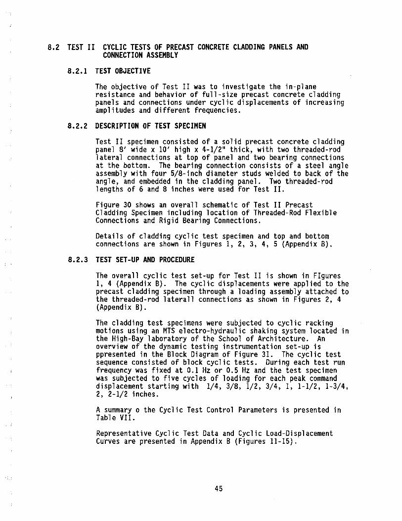
8.2 TEST II CYCLIC TESTS OF PRECAST CONCRETE CLADDING PANELS AND CONNECTION ASSEMBLY
8.2.1 TEST OBJECTIVE
The objective of Test II was to investigate the in-plane resistance and behavior of full-size precast concrete cladding panels and connections under cyclic displacements of increasing amplitudes and different frequencies.
8.2.2 DESCRIPTION OF TEST SPECIMEN
Test II specimen consisted of a solid precast concrete cladding panel 8' wide x 10' high x 4-1/2" thick, with two threaded-rod lateral connections at top of panel and two bearing connections at the bottom. The bearing connection consists of a steel angle assembly with four SIB-inch diameter studs welded to back of the angle, and embedded in the cladding panel. Two threaded-rod lengths of 6 and 8 inches were used for Test II.
Figure 30 shows an overall schematic of Test II Precast Cladding Specimen including location of Threaded-Rod Flexible Connections and Rigid Bearing Connections.
Details of cladding cyclic test specimen and top and bottom connections are shown in Figures 1, 2, 3, 4, 5 (Appendix B).
8.2.3 TEST SET-UP AND PROCEDURE
The overall cyclic test set-up for Test II is shown in FIgures 1, 4 (Appendix B). The cyclic displacements were applied to the precast cladding specimen through a loading assembly attached to the threaded-rod laterall connections as shown in Figures 2, 4 (Appendix B).
The cladding test specimens were subjected to cyclic racking motions using an MTS electro-hydraulic shaking system located in the High-Bay laboratory of the School of Architecture. An overview of the dynamic testing instrumentation set-up is ppresented in the Block Diagram of Figure 31. The cyclic test sequence consisted of block cyclic tests. During each test run frequency was fixed at 0.1 Hz or 0.5 Hz and the test specimen was subjected to five cycles of loading for each peak command displacement starting with 1/4, 3/8, 1/2, 3/4, 1, 1-1/2, 1-3/4, 2, 2-1/2 inches.
A summary 0 the Cyclic Test Control Parameters is presented in Table VII.
Representative Cyclic Test Data and Cyclic Load-Displacement Curves are presented in Appendix B (Figures 11-15).
45
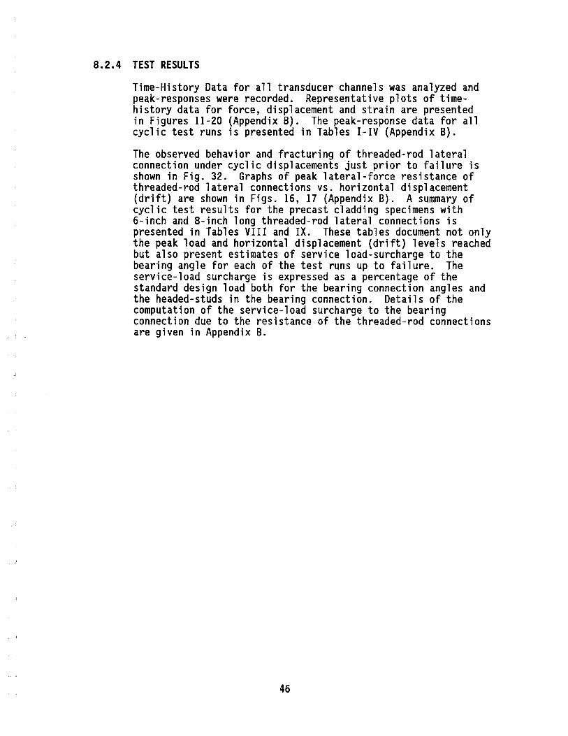
8.2.4 TEST RESULTS
Time-History Data for all transducer channels was analyzed and peak-responses were recorded. Representative plots of timehistory data for force, displacement and strain are presented in Figures 11-20 (Appendix B). The peak-response data for all cyclic test runs is presented in Tables I-IV (Appendix B).
The observed behavior and fracturing of threaded-rod lateral connection under cyclic displacements just prior to failure is shown in Fig. 32. Graphs of peak lateral-force resistance of threaded-rod lateral connections vs. horizontal displacement (drift) are shown in Figs. 16, 17 (Appendix B). A summary of cyclic test results for the precast cladding specimens with 6-inch and 8-inch long threaded-rod lateral connections is presented in Tables VIII and IX. These tables document not only the peak load and horizontal displacement (drift) levels reached but also present estimates of service load-surcharge to the bearing angle for each of the test runs up to failure. The service-load surcharge is expressed as a percentage of the standard design load both for the bearing connection angles and the headed-studs in the bearing connection. Details of the computation of the service-load surcharge to the bearing connection due to the resistance of the threaded-rod connections are given in Appendix B.
46
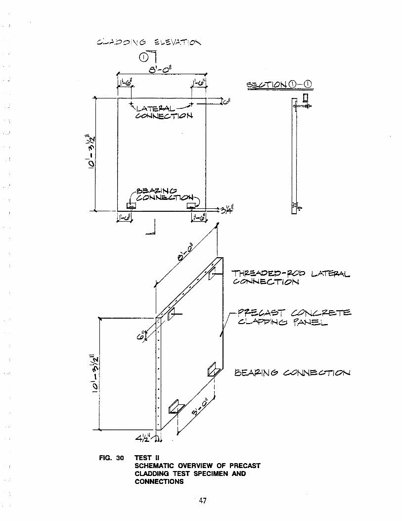
N \<' , <l
c...~,.:.,::?~i\l0 ~\....~V~:!!O,
CDI et-011
M- ~~ 6SVTION (i)-CD
--
FIG. 30
+\.LATE.ML.~-t ~t-Jec.. TI-"N.
~~I'rJ,(;) C,O~~~
J
TEST II
J
P1-ec..~T t:.ON~;z.E:.-re:. C.LAPPIt-4,,=, f ~E..L.
SCHEMATIC OVERVIEW OF PRECAST CLADDING TEST SPECIMEN AND CONNECTIONS
47

.;::.
(Xl
"" """"'"
, """""""""""""""""';
,
, ,
, ,
, ~
LEBO
W U~IVERSAL
: :
LOAD
CEL
L (1
) :
: MO
DEL
3115
±IO
KIP
S '
: HO
NEYW
ELL
VISI
CORD
ER
MODE
L 18
58
8 CH
. 3
CH.
, , , , , ~ LV
DT C
OLLI
NS
(2)
: SS
-212
~
±4
INCH
ES
I J 8
CHAN
NELS
MU
X TI
ME
INCL
UDIN
G PL
UG-IN
SY
NC.
, , : AC
CELE
ROM
ETER
S (3
) i
0 ST
ATHA
M A
5-5-
350
, , , , ,
, ,
"Ii"
""""
""""
""""
""""
""""
""""
""""
""""
""""
""""
.
COND
ITIO
NING
MO
DULE
S l ST
ART/
STOP
I MT
S EL
ECTR
O-HY
DRAU
LIC
SYST
EM
FUNC
TION
GEN
ERAT
OR
AND
CONT
ROL
MODU
LE
CAME
RA
TV-V
CR
(AS
NEED
ED)
BLOC
K DI
AGRA
M
HP 3
960
A
INST
RUM
ENTA
TION
~
FM T
APE
TIM
E RE
CORD
ER
4 CH
ANNE
LS
I SY
NC.
J
DYNA
MIC
TEST
ING
INST
RUM
ENTA
TION
l D
ATA
PROC
ESSI
NG
DEMU
X
PC B
ASED
VI
PAC
DATA
AC
QUIS
ITIO
N SY
STEM
FIGU
RE
31
NSF
SPON
SORE
D RE
SEAR
CH P
ROJE
CT
SEIS
MIC
TES
TING
OF
HEAV
Y PR
ECAS
T FA
CADE
S/CLA
DDIN
G PA
NEL
AND
CONN
ECTI
ONS
PREP
ARED
BY;
DR
. GA
RY G
RANN
EMAN
, ET
/EL
DEPT
. DA
TE:
8/86
PRIN
CIPA
L IN
VEST
IGAT
OR:
DR.
SAT
RIHA
L,
ARCH
. EN
GR.
DEPT
. CA
LIFO
RNIA
POL
YTEC
HNIC
STA
TE U
NIVE
RSIT
Y,
SAN
LUIS
OBI
SPO,
CA
LIFO
RNIA
934
07

~
~
SPEC
IMEN
FPCR
T-L6
FPCR
T-L8
NSF
SPON
SORE
D RE
SEAR
CH P
ROJE
CT
SEIS
MIC
TES
TING
OF
HEAV
Y PR
ECAS
T FA
CADE
S/CLA
DDIN
G &
CONN
ECTI
ONS
TABL
E V
Ir:
SUMM
ARY
OF D
YNAM
IC T
EST
CONT
ROL
PARA
MET
ERS
PREC
AST
CONC
RETE
CLA
DDIN
G PA
NEL
WIT
H TH
READ
ED-R
OD L
ATER
AL
FREQ
UENC
Y NO
. OF
BL
OCK
CYCL
IC T
EST
CONN
ECTI
ONS
@ TO
P &
BEAR
ING
Hz
CYCL
ES
COMM
AND
PEAK
DIS
PLAC
EMEN
T OF
CYC
LES
-IN
CHES
CO
NNEC
TION
S @
BOTT
OM
SIZE
PA
NEL
THRE
AD-R
OD
1 2
3 4
5 6
7 B
TH
ICKN
ESS
LENG
TH
INCH
ES
INCH
ES
±1/4
±3
/8
±1/2
±3
/4
±1
±l
1/2
±1
3/4
±2
0.1
5 X
X
X
X
X
X
8'·
0" W
IDE
x 1
0'·
0"
HIG
H
4 1/
2 6
Run
#7
0.5
5 X
X
X
X
X
X
0.1
5 X
X
X
X
X
X
8' -
a .. W
IDE
x 1
0'·
0"
HIG
H
4 1/
2 8
0.5
5 X
X
X
X
X
X
X
9
±2 1
/2
Run
#8
X
12
1/4
X
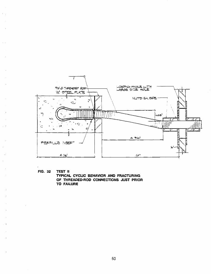
c.
LI
~!eJ tP ~ ~-+-----, vz.' ~"'T'EE.L PLATE -+--....
c . ~
FIG. 32 TEST II TYPICAL CYCUC BEHAVIOR AND FRACTURING OF THREADED-ROD CONNECTIONS JUST PRIOR TO FAILURE
50
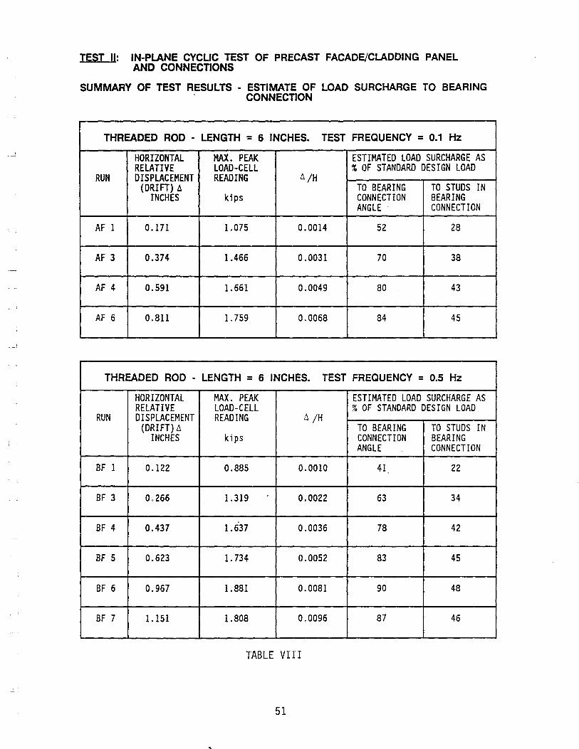
TEST II: IN-PLANE CYCUC TEST OF PRECAST FACADE/CLADDING PANEL AND CONNECTIONS
SUMMARY OF TEST RESULTS - ESTIMATE OF LOAD SURCHARGE TO BEARING . CONNECTION
THREADED ROD - LENGTH = 6 INCHES. TEST FREQUENCY = 0.1 Hz
HORIZONTAL MAX. PEAK ESTIMATED LOAD SURCHARGE AS RELATIVE LOAD-CELL % OF STANDARD DESIGN LOAD
RUN DISPLACEMENT READING Ll /H (DRIFT) II TO BEARING TO STUDS IN
INCHES kips CONNECTION BEARING ANGLE CONNECTION
AF 1 0.171 1.075 0.0014 52 28
AF 3 0.374 1.466 0.0031 70 38
AF 4 0.591 1.661 0.0049 80 43
AF 6 0.811 1.759 0.0068 84 45
THREADED ROD - LENGTH = 6 INCHES. TEST FREQUENCY = 0.5 Hz
HORIZONTAL MAX. PEAK ESTIMATED LOAD SURCHARGE AS RELATIVE LOAD-CELL % OF STANDARD DESIGN LOAD
RUN DISPLACEMENT READING Ll /H (DRIFT) II TO BEARING TO STUDS IN
INCHES kips CONNECTION BEARING ANGLE CONNECTION
BF 1 0.122 0.885 0.0010 41 22
BF 3 0.266 1.319 0.0022 63 34
BF 4 0.437 1.637 0.0036 78 42
BF 5 0.623 1.734 0.0052 83 45
BF 6 0.967 1.881 0.0081 90 48
BF 7 1.151 1.808 0.0096 87 46
TABLE VIII
51
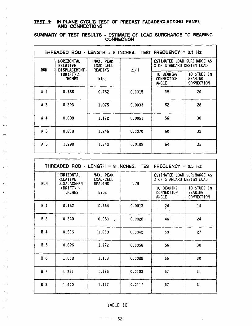
, ,
TEST II: IN-PLANE CYCUC TEST OF PRECAST FACADE/CLADDING PANEL AND CONNECTIONS
SUMMARY OF TEST RESULTS - ESTIMATE OF LOAD SURCHARGE TO BEARING CONNECTION
THREADED ROD - LENGTH = 8 INCHES. TEST FREQUENCY = 0.1 Hz
HORIZONTAL MAX. PEAK ESTIMATED LOAD SURCHARGE AS RELATIVE LOAD-CELL % OF STANDARD DESIGN LOAD
RUN DISPLACEMENT READING il/H (DRIFT) ~ TO BEARING TO STUDS IN
INCHES kips CONNECTION BEARING ANGLE CONNECTION
A 1 0.186 0.782 0.0015 38 20
A 3 0.393 1.075 0.0033 52 28
A 4 0.608 1.172 0.0051 56 30
A 5 0.838 1.246 0.0070 60 32
A 6 1.290 1.343 0.0108 64 35
THREADED ROD - LENGTH = 8 INCHES. TEST FREQUENCY = 0.5 Hz
HORIZONTAL MAX. PEAK ESTIMATED LOAD SURCHARGE AS RELATIVE LOAD-CELL % OF STANDARD DESIGN LOAD
RUN DISPLACEMENT READING 6/H (DRIFT) 6 TO BEARING TO STUDS IN
INCHES kips CONNECTION BEARING ANGLE CONNECTION
B 1 0.152 0.554 0.0013 26 14
B 3 0.340 0.953 0.0028 46 24
B 4 0.506 1.050 0.0042 50 27
B 5 0.696 1.172 0.0058 56 30
B 6 1.058 1.163 0.0088 56 30
B 7 1. 231 1.196 0.0103 57 31
B 8 1.400 1.197 0.0117 57 31
TABLE IX
-- 52
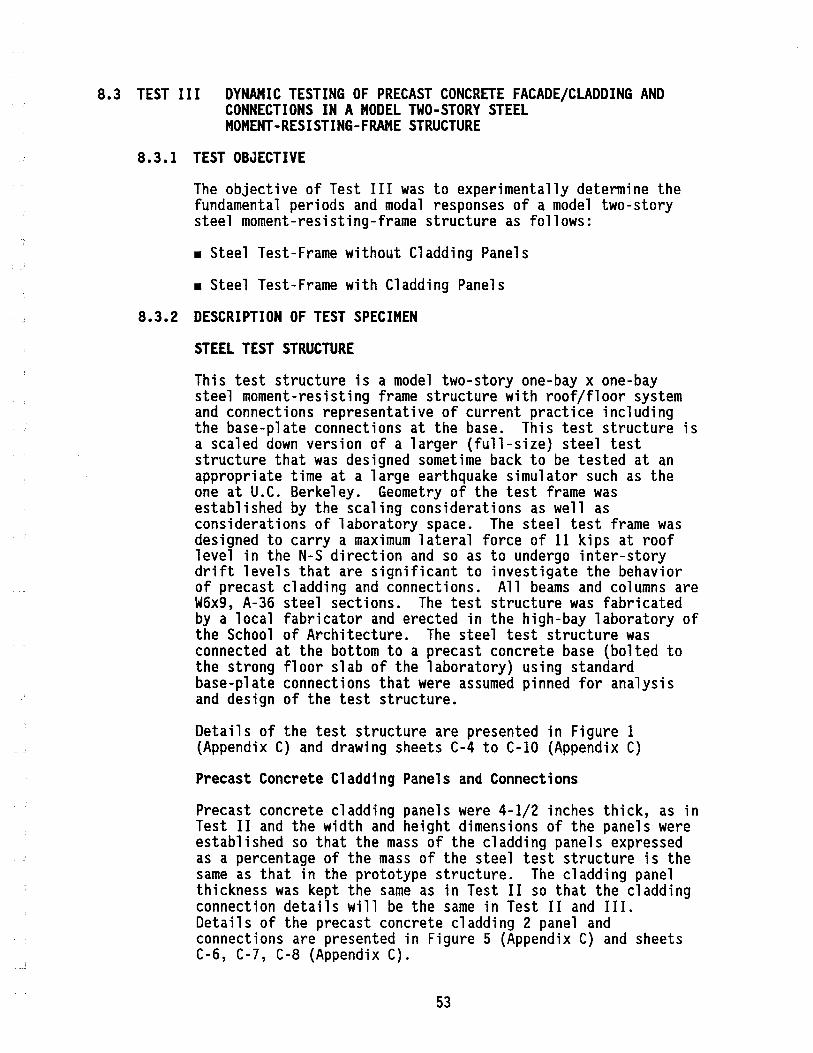
8.3 TEST III DYNAMIC TESTING OF PRECAST CONCRETE FACADE/CLADDING AND CONNECTIONS IN A MODEL TWO-STORY STEEL MOMENT-RESISTING-FRAME STRUCTURE
8.3.1 TEST OBJECTIVE
The objective of Test III was to experimentally determine the fundamental periods and modal responses of a model two-story steel moment-resisting-frame structure as follows:
• Steel Test-Frame without Cladding Panels
• Steel Test-Frame with Cladding Panels
8.3.2 DESCRIPTION OF TEST SPECIMEN
STEEL TEST STRUCTURE
This test structure is a model two-story one-bay x one-bay steel moment-resisting frame structure with roof/floor system and connections representative of current practice including the base-plate connections at the base. This test structure is a scaled down version of a larger (full-size) steel test structure that was designed sometime back to be tested at an appropriate time at a large earthquake simulator such as the one at U.C. Berkeley. Geometry of the test frame was established by the scaling considerations as well as considerations of laboratory space. The steel test frame was designed to carry a maximum lateral force of 11 kips at roof level in the N-S direction and so as to undergo inter-story drift levels that are significant to investigate the behavior of precast cladding and connections. All beams and columns are W6x9, A-36 steel sections. The test structure was fabricated by a local fabricator and erected in the high-bay laboratory of the School of Architecture. The steel test structure was connected at the bottom to a precast concrete base (bolted to the strong floor slab of the laboratory) using standard base-plate connections that were assumed pinned for analysis and design of the test structure.
Details of the test structure are presented in Figure 1 (Appendix C) and drawing sheets C-4 to C-I0 (Appendix C)
Precast Concrete Cladding Panels and Connections
Precast concrete cladding panels were 4-1/2 inches thick, as in Test II and the width and height dimensions of the panels were established so that the mass of the cladding panels expressed as a percentage of the mass of the steel test structure is the same as that in the prototype structure. The cladding panel thickness was kept the same as in Test II so that the cladding connection details will be the same in Test II and III. Details of the precast concrete cladding 2 panel and connections are presented in Figure 5 (Appendix C) and sheets C-6, C-7, C-8 (Appendix C).
53

The cladding configuration and connection details were developed in consultation with a Precast Manufacturer (89) on the west coast who also fabricated the cladding panels in accordance with current practices of manufacture of architectural precast cladding panels including their connections.
8.3.3 DYNAMIC TEST SET-UP AND PROCEDURE
The test structure was dynamically excited by an APS ElectroSeis shaker positioned on the floor of the test structure. This shaker could be oriented in the Transverse direction (N-S) or the Longitudinal direction (E-W). For study of torsional response characteristics this shaker was positioned 12 inches off-center on the floor of test structure in the Transverse direction (N-S).
Figures 2 and 4 (Appendix C) show photographs of the APS shaker and Test III in progress.
Basically Test III was divided into three separate parts:
Test III-A Steel Test Frame Structure without Precast Cladding Panels.
Test 111-8 Steel Test Frame Structure with One Precast Cladding Panel attached to east face of the structure.
Test III-C Steel Test Frame Structure with Two Precast Cladding Penels, attached one each to the east and west faces of the structure.
Two types of excitations were used in Test III, as follows:
• Random Excitation This was provided by the HP Spectrun Analyzer used in this test.
• Sinusoidal Excitation This was provided by a function generator used in this test.
A schematic block diagram of Dynamic Test Set-up is shown in Fig. 33.
The sequence of the Dynamic Test Runs and Test Control Parameters are presented in Table X.
For each test run the selected excitation was continuously applied and dynamic responses of test structure at roof & floor levels measured by appropriately positioned statham accelerometers.
54
Modal response of the test structure was obtained by feeding the accelerometer output into the HP Spectrum Analyzer Fig. 3 (Appendix C) which provided a screen display of modal response and then dumping the screen-display down to an x-y plotter.
Figure 1 (Appendx C) shows the overall dynamic test set-up. Figures 2 & 3 (Appendix C) show the test instrumentation and in Test III.
8.3.4 Test Results
A summary of test results obtained for Test III-A (No Cladding Panels) is presented in Table XI.
A summary of test results obtained for Test III-C (Test Structure with Two Cladding Panels in Transverse Direction N-S) is presented in Table XII.
55
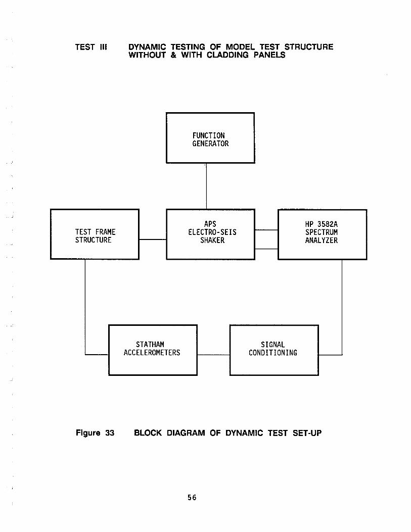
TEST III
TEST FRAME STRUCTURE
Figure 33
DYNAMIC TESTING OF MODEL TEST STRUCTURE WITHOUT & WITH CLADDING PANELS
STATHAM ACCELEROMETERS
FUNCTION GENERATOR
APS ELECTRO-SEIS
SHAKER
SIGNAL CONDITIONING
HP 3582A SPECTRUM ANALYZER
BLOCK DIAGRAM OF DYNAMIC TEST SET-UP
56

(J1
.....
..
TYPE
OF
EXCI
TATI
ON
RAND
OM
SINU
SOID
AL
TEST
III
DY
NAMI
C TE
STIN
G OF
MOD
EL S
TEEL
TES
T ST
RUCT
URE
TEST
RUN
II
I-A
TE
ST R
UN
II 1
-8
STEE
L TE
ST F
RAME
WIT
HOUT
ST
EEL
TEST
FRA
ME W
ITH
ONE
CLAD
DING
PAN
ELS
CLAD
DING
PAN
EL A
TTAC
HED
TO E
AST
FACE
OF
TEST
STR
UCTU
RE
ORIE
NTAT
ION
OF S
HAKE
R OR
IENT
ATIO
N OF
SHA
KER
LONG
ITU-
TRAN
SVER
SE
DINA
L DI
RECT
ION
DIRE
CTIO
N N-
S E-
W
X
X
X
X
OFF-
CENT
ER
LONG
ITU-
TRAN
SVER
SE
TRAN
SVER
SE
DINA
L DI
RECT
ION
DIRE
CTIO
N DI
RECT
ION
N-S
N-S
E-W
X
X
X
X
X
X
TABL
E X
DY
NAMI
C TE
ST R
UNS
AND
TEST
PAR
AMET
ERS
OFF-
CENT
ER
TRAN
SVER
SE
DIRE
CTIO
N N-
S X
X
TEST
RUN
II
I-C
STEE
L TE
ST F
RAME
WIT
H TW
O PR
ECAS
T CL
ADDI
NG P
ANEL
S AT
TACH
ED O
NE E
ACH
TO T
HE E
AST
AND
WES
T FA
CES
OF T
HE
TEST
STR
UCTU
RE
ORIE
NTAT
ION
OF S
HAKE
R
LONG
ITU-
OFF-
CENT
ER
TRAN
SVER
SE
DINA
L TR
ANSV
ERSE
DI
RECT
ION
DIRE
CTIO
N DI
RECT
ION
N-S
E-W
N-
S
X
X
X
X
X
X

, ~1
TEST III-A
MODE
First Translational Mode
Second Translational Mode
First Torsional Mode
Second Torsional Mode
DYNAMIC TEST OF MOMENT-RESISTING STEEL FRAME STRUCTURE WITHOUT PRECAST CONCRETE FACADE/CLADDING PANELS
NATURAL FREQUENCY Hz
SHORT LONGITUDINAL TORSION DIRECTION DIRECTION
N-$ E-W
7.0 Hz 10.6 Hz
19.75 Hz 39.6 Hz
13.0 Hz
43.0 Hz
Table XI SUMMARY OF TEST RESULTS TEST III-A
58

TEST III-C
MODE
First Translational Mode
Second Translational Mode
First Torsional Mode
Second Torsional Mode
DYNAMIC TEST OF MOMENT-RESISTING STEEL FRAME STRUCTURE WITH TWO PRECAST CLADDING PANELS ATTACHED ONE EACH TO THE EAST AND WEST FACES (SHORT DIRECTION) OF TEST STRUCTURE
NATURAL FREQUENCY Hz
SHORT LONGITUDINAL TORSION DIRECTION DIRECTION
N-S E-W
5.9 Hz 7.4 Hz
17.0 Hz 34.5 Hz
9.2 Hz
34.8 Hz
Table XII SUMMARY OF TEST RESULTS TEST III-C
59

CHAPTER 9: ANALYTICAL MODELING OF BEHAVIOR OF CLADDING AND CONNECTIONS
• Behavior of Thread-Rod Flexible Connections [TEST I]
Based on an experimentally obtained stress-strain curve for a S/8-inch diameter threaded-rod, an analytical model for load-deflection prediction of contilever threaded-rod specimens with support conditions similar to those used in practice, was developed.
Details of the analytical model development process are presented below (p.62-66). Figure 34 shows the assumed stress and strain distribution for the cantilever threaded-rod specimens. A block diagram outlining the steps involved in the analytical prediction model is shown in Figure 3S. Details of the derivations required to obtain theoretical moment-curvature relations and load-deflection relations are presented on p.6S-66.
A polynominal fit to experimental stress-strain curve for a S/8-inch diameter threaded steel-rod specimen is presented in Figure 13 (Appendix A).
The moment-curvature curve that was obtained with this analytical model is shown in Figure 14 (Appendix A).
Results in the form of Load-Deflection curves obtained with this analytical prediction model for threaded-rod specimens of 4, 6, 8, 10 and 12 inch lengths are presented in Figures 7-11 (Appendix A).
• In-Plane Behavior of Precast Facades/Claddings and Connection Assemblies [TEST II]
The behavior of full-scale precast facadeslcladdings and connection assemblies is very complex, especially under cyclic motions. In light of these complexities only practical and simplified analytical evaluation of results of Test II was carried out.
The basic objective of this analytical evaluation was to obtain an overall behavior model, based on cyclic test results of Test II, and compare this model to the conceptual behavior model used in seismic analysis and design of precast cladding and connections.
Based on peak cyclic lateral force and peak cyclic displacements levels reached in each run of Test II, the proposed analytical behavior model was based on the assumption that the peak lateral-force resistance is controlled by the resistance of the top flexible threaded-rod connections. This concept is presented graphically in Figure 36. A seismic design evaluation of the cladding panel and connections was made to determine if any design changes were necessary to account for the lateral-force resistance provided by the threaded-rod flexible connections.
In any case, the fact remains that a great deal of work needs to be done to improve our understanding of the behavior of cladding panels and connections especially under cyclic motions.
60
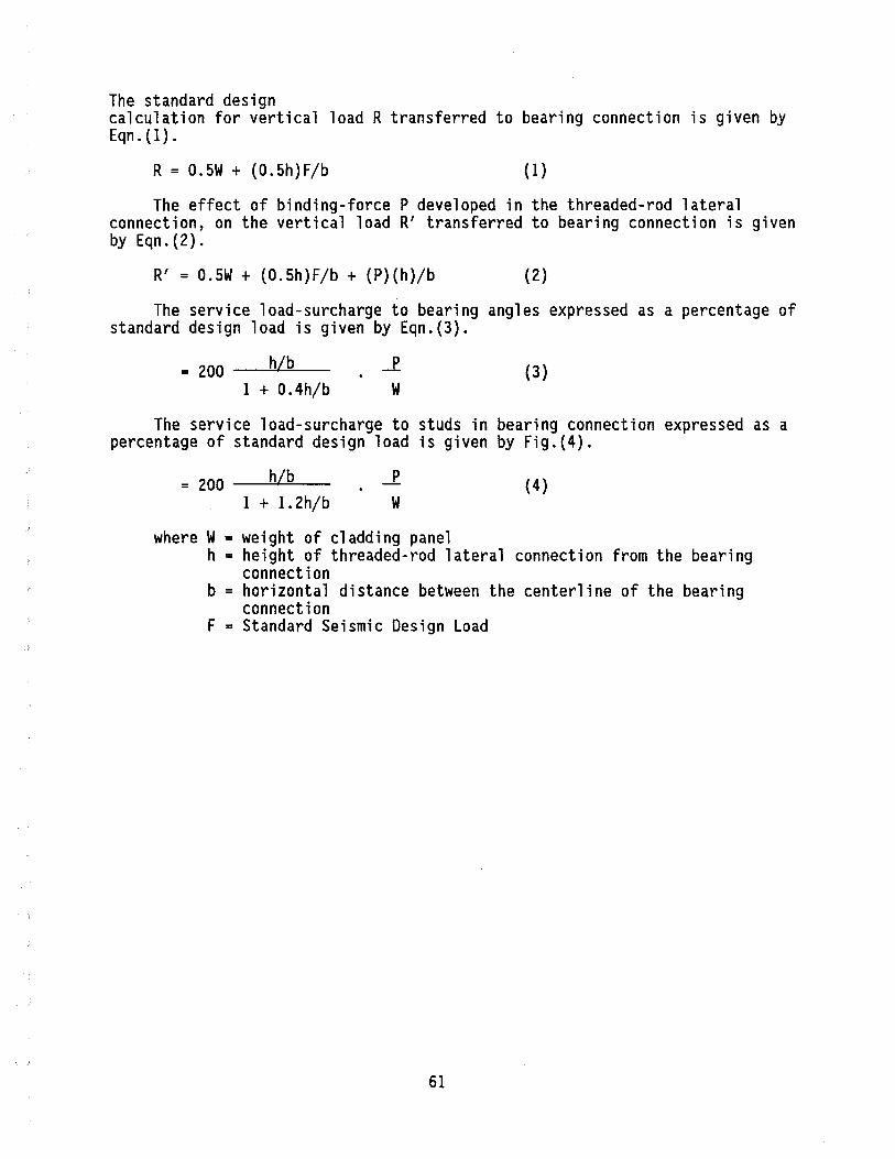
The standard design calculation for vertical load R transferred to bearing connection is given by Eqn.(l).
R = 0.5W + (0.5h)F/b (1 )
The effect of binding-force P developed in the threaded-rod lateral connection, on the vertical load R' transferred to bearing connection is given by Eqn. (2) .
R' = 0.5W + (0.5h)F/b + (P)(h)/b (2)
The service load-surcharge to bearing angles expressed as a percentage of standard design load is given by Eqn.(3).
= 200 _~h/....:::b~_ 1 + O.4h/b
(3)
The service load-surcharge to studs in bearing connection expressed as a percentage of standard design load is given by Fig.(4).
= 200 _~h/....:::b __ (4) 1 + 1.2h/b W
where W = weight of cladding panel h = height of threaded-rod lateral connection from the bearing
connection b = horizontal distance between the centerline of the bearing
connection F = Standard Seismic Design Load
61
• Modal Response of Two-Story Steel Moment-Resisting Frame Structure With and Without Precast Concrete Cladding Panels (TEST III)
The analytical evaluation of modal response results obtained during Test III is still in progress.
A mode-shape and frequency analysis of the test structure without any cladding panels was carried out using the computer program ETABS, using appropriate modeling to simulate the pinned-base condition assumed. The modal frequencies obtained are presented in Table XIII.
62

F
I L ___ -+-
L
CANTILEVER THREADEDROD SPECIMEN
I I I '--------
.AI.\
Ce...
STRAIN DIAGRAM
[ dY)] cr (y) = cr e £ E 5. E e 0 r Y 5. Y
e
[ dY)]" cr (y) = cr e -E-
e
FIG. 34
E > E e
or Y > Y
STRESS DIAGRAM
ANAL VTICAL MODEL FOR LOAD-DEFLECTION PREDICTION TEST I: TESTS OF THREADED-ROD FLEXIBLE CONNECTIONS
63
x

VARIABLES AND PARAMETERS
P: LOAD, LBS. L: ROD LENGTH - INCHES E: ROD ELASTICITY r: ROD RADIUS, INCHES ¢: CURVATURE = E IR=E IY r e 0: END DEFLECTION OF
ROD ALONE 0c: END DEFLECTION DUE
TO ROTATION OF RIGID CONNECTION 0T: ° + 0c: TOTAL END DEFLECTION
a(y): STRESS AT Y E(Y): STRAIN AT Y
n: STRAIN HARDENING EXPONENT E : STRAIN AT y = r
r Ee: STRAIN AT YIELD, Y = Y a: STRESS AT YIELD, Y = Y
e Y: DISTANCE ELASTIC ZONE EXTENDS
ABOVE AND BELOW ROD CENTERLINE
m(¢): MOMENT CORRESPONDING TO CURVATURE ¢ X(P,L; m(¢)): LOCATION ALONG ROD CORRESPONDING TO CURVATURE ¢
amax(P,L): MAXIMUM STRESS IN ROD FOR GIVEN P,L CS: CANTILEVER CONNECTION STIFFNESS, LB-IN/RADIAN
ANALYTICAL MODEL FOR LOAD-DEFLECTION PREDICTION TEST I: TESTS OF THREADED-ROD LATERAL CONNECTIONS
64
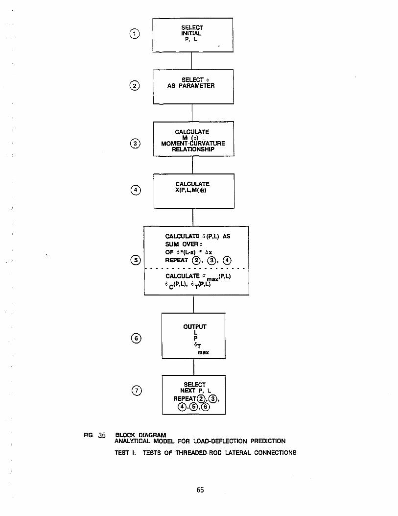
SELECT INITIAL
P, L -
SELECT 4> AS PARAMETER
CALCULATE M (4)) _
MOMENT-CURVATURE RELATIONSHIP
CALCULATE X(P,L,M( $»
CALCULATE 0 (P,L) AS SUM OVER$ OF $*(L-x) * t.x
REPEAT ®, ®, 0 - - - - - - - - -- - - - - - - - - -
CALCULATE cr max(P,L) <5 C(P,L), 15 T(P,L)
OUTPUT L P °T max
SELECT NEXT P, L
REPEAT®,®,
0,®,®
FIG. 35 BLOCK DIAGRAM ANAL 'aICAL MODEL FOR LOAD-DEFLECTION PREDICTION
TEST I: TESTS OF THREADED-ROD LATERAL CONNECTIONS
65

COMPUTATION OF m(¢) [BLOCK ~]: MOMENT-CURVATURE
(i) For a specific value of Y, the moment m(Y) producing corresponding state of stress/strain is:
= 4ae[ ~(y/y)y Vr2-y2 dy +; (y/y)ny Vr2_y2 dy] o y
(ii) Substitute ¢ for Y where Y = Ee/¢ = 0e/E ¢
(iii) Numerically this is calculated as a sum over I
where ~YI is incremented from 0 to r
66

COMPUTATION OF X{p,L,m{~» [BLOCK (!) ]
(i) For cantilever
m = P * (L-X)
(II) Then
I X(P,L;m(~» = L - m{~)/P
COMPUTATION OF cS(P,L) [BLOCK@]
( i) o
(P,L) = f<P*[L-X(~)] * dx(~) L
P
I====l-)X L
m
o
~
L - X
dx --7 X o L
(ii) Numerically this is calculated using ~J as a parameter and summing over J:
(P,L) = l:H~J*[L-X(~J)] + ~J-l*[L-X(~J-l)]} * [X(~j_l)-X(~J)] J
The moment enters implicitly through X{P,L;m{~»
X is computed for sequential ~J pairs. The iteration sensitivity is
interactively varied to assure adequate precision.
COMPUTATION OF cr max & crT [BLOCK @]
(i)
(i i )
67
where 2Ymin is the depth of
elastic zone when m=~ax = P·L
where CS is the stiffness, Lb.-In./Rad.
of the support connection of cantilever
threaded rod

-+ +
f~. ~W
.cp-I
qJ I
CONCEPTUAL MODEL OF STANDARD DESIGN PROCEDURE FOR VERTICAL LOAD TRANSFER TO BEARING CONNECTIONS
+ <l \ + I 61
T
F<?~W t. -2.
I I lJ:J q:J
I
~~I ~ b L
CONCEPTUAL MODEL OF MODIFIED DESIGN PRODECURE FOR VERTICAL LOAD TRANSFER TO BEARING CONNECTION
Figure 36 Test II Conceptual Simple Behavior Model for Seismic Analysis and Design of Cladding Panels Connections
68
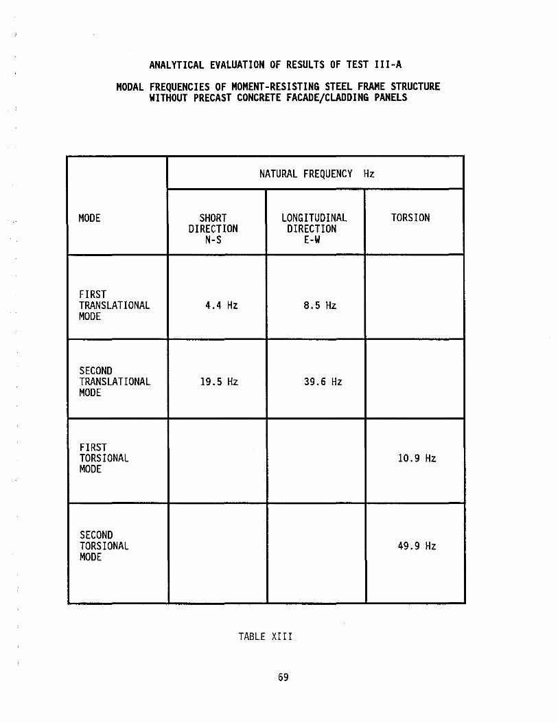
ANALYTICAL EVALUATION OF RESULTS OF TEST III-A
MODAL FREQUENCIES OF MOMENT-RESISTING STEEL FRAME STRUCTURE WITHOUT PRECAST CONCRETE FACADE/CLADDING PANELS
NATURAL FREQUENCY Hz
MODE SHORT LONG ITUD INAL TORSION DIRECTION DIRECTION
N-S E-W
FIRST TRANSLATIONAL 4.4 Hz 8.5 Hz MODE
SECOND TRANSLATIONAL 19.5 Hz 39.6 Hz MODE
FIRST TORSIONAL 10.9 Hz MODE
SECOND TORSIONAL 49.9 Hz MODE
TABLE XIII
69

CHAPTER 10: DISCUSSION OF RESULTS AND CONCLUSIONS
BEHAVIOR OF LATERAL/THREADED-ROD CONNECTIONS [TEST I]
• A study of the results of Test I specimens shows that load-capacity of threaded-rod cladding connections decreases with increasing length.
• Behavior of threaded-rod specimen in uniaxial tension shows evidence of strain-hardening that must be considered in design and analysis.
• Load-Deflection behavior of cantilever threaded-rod specimens can be predicted using experimentally obtained stress-strain data with reasonably good correlation between experimental and analytical results. Simple elastic beam theory does not appear to be adequate to explain the load-deflection behavior obtained in these static tests.
CYCLIC BEHAVIOR OF PRECAST CONCRETE CLADDING PANELS AND CONNECTION ASSEMBLY [TEST II]
• In-plane resistance of precast concrete cladding panels is controlled by the resistance provided by the threaded-rod lateral connections at top of panels.
• In all cyclic test runs failure occurred in the threaded-rods at the loading-end of top lateral connections.
• The levels of inter-story drift that can be accommodated by the threaded-rod lateral connections can be established from the drifts at failure which varied from 0.0068 H at 0.1 Hz [6-inch threaded-rod length] to 0.0117H at 0.5 Hz [8-inch threaded-rod length].
• Behavior of threaded-rod connections under cyclic displacements shows that further studies are needed to explain the fracturing mechanism of failures observed possibly caused by low-cycle fatigue.
• The lateral-force resistance offered by the threaded-rod lateral connections at top of panels results in a service-load surcharge on the bearing connections at bottom of the panels, which should be taken into account in the seismic design of precast concrete cladding and connection assemblies.
INFLUENCE OF PRECAST CONCRETE CLADDING PANELS ON MODAL RESPONSE OF STEEL FRAME TEST STRUCTURE [TEST III]
• A preliminary study of the results of shaking tests carried out in Test III shows that the addition of precast cladding panels to the test structure reduced the first translation mode frequency from 7 Hz to 5.9 Hz. (approx. 15.71%) and second translational mode frequency from 19.75 Hz to 17 Hz (approx. 13.92%) in the transverse direction, i.e., parallel to the plane of the cladding panels. These preliminary results show that the stiffening effects of precast concrete cladding are significant and must be considered in the seismic design and analysis of buildings.
70

BIBLIOGRAPHY
1. AUTHOR: Adham, S.A.
TITLE: Out-of-Plane Response of Masonry Walls
SOURCE: Proceedings, Third North American Masonry Conference, June 1985, University of Texas, Arlington, Texas
KEYWORDS: Masonry, Out-of-Plane Seismic Loading, Testing, Walls
2. AUTHOR: AlA Research Corporation
TITLE: Seismic Design for Police and Fire Stations
SOURCE: AlA Research Corporation, Washington D.C., 1978
KEYWORDS: Earthquakes, Design, Criteria, Building Components
3. AUTHOR: Algan, Bekir
TITLE: Drift and Damage Considerations in Earthquake Resistant Design of Reinforced Concrete Buildings
SOURCE: University of Illinois at Urbana-Champaign, 1976
KEYWORDS: Earthquakes, Drift, Damage, Reinforced Concrete
4. AUTHOR: Allen, Edward
TITLE: The Professional Handbook of Building Construction
SOURCE: John Wiley & Sons, New York, 1985
KEYWORDS: Cladding, Basic Concepts, Design Requirements, Precast Concrete, Curtain Walls, Masonry, Stone, Veneer, Construction, Details, Building Codes, Building Case Studies
5. AUTHOR: Armhein, James; Kesler, James; Thompson, Leonard; Van Houten, John
TITLE: Masonry Design Manual
SOURCE: Masonry Industry Advancement Committee, 1979
KEYWORDS: Masonry, Veneer, Construction, Details, Practice
71
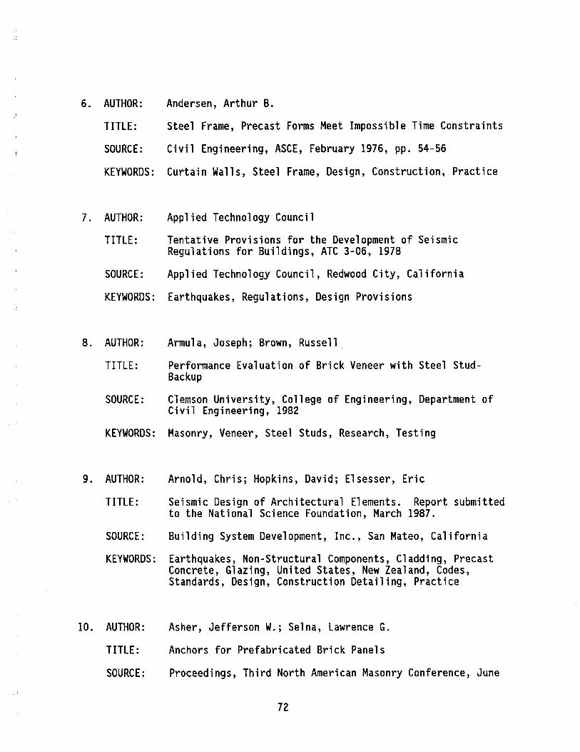
6. AUTHOR: Andersen, Arthur B.
TITLE: Steel Frame, Precast Forms Meet Impossible Time Constraints
SOURCE: Civil Engineering, ASCE, February 1976, pp. 54-56
KEYWORDS: Curtain Walls, Steel Frame, Design, Construction, Practice
7. AUTHOR: Applied Technology Council
TITLE: Tentative Provisions for the Development of Seismic Regulations for Buildings, ATC 3-06, 1978
SOURCE: Applied Technology Council, Redwood City, California
KEYWORDS: Earthquakes, Regulations, Design Provisions
8. AUTHOR: Armula, Joseph; Brown, Russell
TITLE: Performance Evaluation of Brick Veneer with Steel StudBackup
SOURCE: Clemson University, College of Engineering, Department of Civil Engineering, 1982
KEYWORDS: Masonry, Veneer, Steel Studs, Research, Testing
9. AUTHOR: Arnold, Chris; Hopkins, David; Elsesser, Eric
TITLE: Seismic Design of Architectural Elements. Report submitted to the National Science Foundation, March 1987.
SOURCE: Building System Development, Inc., San Mateo, California
KEYWORDS: Earthquakes, Non-Structural Components, Cladding, Precast Concrete, Glazing, United States, New Zealand, Codes, Standards, Design, Construction Detailing, Practice
10. AUTHOR: Asher, Jefferson W.; Selna, Lawrence G.
TITLE: Anchors for Prefabricated Brick Panels
SOURCE: Proceedings, Third North American Masonry Conference, June
72
II.
1985, University of Texas, Arlington, Texas
KEYWORDS: Prefabrication, Brick, Anchors, Testing, Failure
AUTHOR: Association of the Wall and Ceiling Industries Internat i ona 1 and Metal Lath/Steel Framing Association
TITLE: Steel Framing Systems Manual
SOURCE: Association of the Wall and Ceiling Industries Internat i ona 1 and Metal Lath/Steel Framing Association, 1979
KEYWORDS: Facades, Metal Studs, Lath, Details, Erection, Practice
12. AUTHOR: Ayres, J. Marx; Sun, T-Y.; Brown, F.R.
TITLE: Non-Structural Damage to Buildings, The Great Alaska Earthquake of 1964: Engineering
SOURCE: National Academy of Sciences, Washington D.C., 1973
KEYWORDS: Earthquakes, Damage, Facades, Glazing, Brick Veneer, Curtain Walls, Case-Studies, Recommendation
13. AUTHOR: Beall, Christine
TITLE: Masonry Design and Detailing
SOURCE: Prentice-Hall, New Jersey, 1984
KEYWORDS: Masonry, Veneer, Construction, Details, Practice
14. AUTHOR: Bell, Glenn R.; Gumpertz, Werner H.
TITLE: Engineering Evaluation of Brick Veneer/Steel Stud Walls
SOURCE: Proceeding, Third North American Masonry Conference, June 1985, University of Texas, Arlington, Texas
KEYWORDS: Brick, Veneer, Steel Stud Walls, Current Practice, Design, Construction
15. AUTHOR: Bertero, V.; Brokken, Steven
73

TITLE: Infills in Seismic Resistant Building
SOURCE: Journal of the Structural Division, ASCE, Vol. 109, No.6, June 1983, pp. 1337-1361
KEYWORDS: Earthquakes, Infills, Masonry, Lightweight Concrete, Reinforced Concrete Frames, Research, Testing, Analysis, Retrofitting, Existing Buildings
16. AUTHOR: Blume, John A. & Associates
TITLE: Report on Structural Damage in Anchorage, Alaska Caused by the Earthquake of March 27, 1964
SOURCE: John A. Blume & Associates, San Francisco, California, January, 1966
KEYWORDS: Earthquakes, Damage, Cladding, Facades, Building Case Studies
17. AUTHOR: Borchelt, J. Gregg
TITLE: Construction Tolerances and Design Considerations for Masonry Veneer and Structural Frames
SOURCE: Proceedings, Third North American Masonry Conference, June 1985, University of Texas, Arlington, Texas
KEYWORDS: Construction, Design, Masonry, Veneer, Structural Frames
18. AUTHOR: Botsai, E.; Goldberg, A.; Fisher, J.; Lagorio, H.; Wosser, T.
TITLE: Architects and Earthquakes
SOURCE: AlA Research Corporation, 1975
KEYWORDS: Earthquakes, Precast Concrete, Cladding, Facades, Damage, Details
19. AUTHOR: Bouwkamp, J.G.; Meehan, J.F.
TITLE: Drift Limitations Imposed by Glass
SOURCE: 2nd World Conference on Earthquake Engineering Vol. 3, 1960
KEYWORDS: Drift Behavior, Glass, Design, Criteria
74
20. AUTHOR: Brick Institute of America
TITLE: Brick Veneer Existing Construction
SOURCE: Technical Notes on Brick Construction, Brick Institute of America, July/August, 1978
KEYWORDS: Masonry, Veneer, Construction, Details, Practice
21. AUTHOR: Brick Institute of America
TITLE: Brick Veneer Existing Construction
SOURCE: Technical Notes on Brick Construction, Sept/Oct 1978
KEYWORDS: Masonry, Veneer, Construction, Details, Practice
22. AUTHOR: Brick Institute of America
TITLE: Brick Veneer Panel and Curtain Walls
SOURCE: Technical Notes on Brick Construction, Brick Institute of America, February, 1980
KEYWORDS: Masonry, Veneer, Brick, Curtain Walls, Construction, Details, Practice
23. AUTHOR: Brokken, S.T.; Bertero, V.V.
TITLE: Studies on Effects of Infills in Seismic Resistant R/C Construction
SOURCE: Earthquake Engineering Research Center Report, University of California, Berkeley, CA, 1981
KEYWORDS: Masonry, Infills, Earthquakes, Research, Analysis
24. AUTHOR: Brookes, A.J.
TITLE: Cladding Methods in New Zealand--A State of the Art Report
SOURCE: Building Research Association of New Zealand, Technical Paper P40
75
KEYWORDS: Claddings, Curtain Walls, Design, GRC, Installing, New Zealand, Panels, Precast, Production, Specifying
25. AUTHOR: Brooks, Alan
TITLE: Cladding of Buildings
SOURCE: Construction Press, London, 1983
KEYWORDS: Precast Concrete Cladding, GRP, GRC, Sheet Metal Cladding, Curtain Walls, Construction, Details, United Kingdom
26. AUTHOR: Brown, R.H.; Brown, M.L.; Dalrympale, G.A.
TITLE: Strength and Behavior of Retrofit Embedments in Masonry
SOURCE: Proceedings, Third North American Masonry Conference, June 1985, University of Texas, Arlington, Texas
KEYWORDS: Masonry, Anchorages, Testing
27. AUTHOR: Brown, Russell H.; Armula, Joseph
TITLE: Brick Veneer with Steel Study Backup - An Analytical Study
SOURCE: Proceedings of the 2nd North American Masonry Conference, August, 1982
KEYWORDS: Masonry, Veneer, Steel Study, Research, Testing
28. AUTHOR: Building Seismic Safety Council
TITLE: NEHRP Recommended Provisions for the Development of Seismic Regulations for New Buildings (Prepared for FEMA): Part 1: Provisions, Part 2: Commentary, Part 3: Appendix
SOURCE: Building Seismic Safety Council, Washington D.C.
KEYWORDS: Earthquakes, Seismic Regulation, FEMA, Research
29. AUTHOR: Canada Mortgage and Housing Corporation
TITLE: Exterior Wall Construction in High-Rise Buildings
76
SOURCE: Canada Mortgage and Housing Corporation, 1980
KEYWORDS: Masonry, Facades, Differential Movements, Details, Practice
30. AUTHOR: Canadian Prestressed Concrete Institute
TITLE: Metric Design Manual
SOURCE: Canadian Prestressed Concrete Institute, 1982
KEYWORDS: Precast Concrete, Design, Details
31. AUTHOR: Cheung, Tong Chun
TITLE: The Seismic Performance of Precast Concrete Facades
SOURCE: M. Arch Thesis, (Dr. S. Rihal, Advisor), School of Architecture and Environmental Design, California Polytechnic State University, San Luis Obispo, June 1985
KEYWORDS: Precast Concrete, Earthquakes, Research
32. AUTHOR: Chin, Ian R.; Stecich, John P.; Erlin, Bernard
TITLE: Design of Thin Stone Veneers on Buildings
SOURCE: Proceeding, Third North American Masonry Conference, June 1985, University of Texas, Arlington, Texas
KEYWORDS: Stone, Veneer, Design
33. AUTHOR: Clough, D.P.
TITLE: Design of Connections for Precast Prestressed Concrete Buildings for the Effects of Earthquakes, Phase Two of the Three-Phase Program
SOURCE: ABAM Engineers Inc., Federal Way, Washington, 98003, (NSF Sponsored Research), March 1985
KEYWORDS: Earthquakes, Precast Concrete, Connections, Research, Analysis, Seismic Design
34. AUTHOR: Dayton Superior Corporation
77

TITLE: Precast-Prestress Concrete Handbook
SOURCE: Dayton Superior Corporation, 1983
KEYWORDS: Precast Concrete, Construction, Details
35. AUTHOR: de Vekey, R.C.
TITLE: Performance Specifications for Wall Ties
SOURCE: Building Research Information Paper, March 1984
KEYWORDS: Cladding, Masonry, Ties, Performance Standards, Tests
36. AUTHOR: Dickey, Walter L.
TITLE: Adhered Veneer in Earthquake, Storm and Prefabrication
SOURCE: Proceedings of the 2nd North American Masonry Conference, August, 1982
KEYWORDS: Masonry, Veneer, Earthquakes, Prefabrication
37. AUTHOR: Dowrick, David J.
TITLE: Earthquake Resistant Design
SOURCE: John Wiley & Sons, London, 1987
KEYWORDS: Architectural Detailing for Cladding, Earthquake Resistance, Details
38. AUTHOR: Eagling, Donald G.
TITLE: Seismic Safety Guide
SOURCE: Lawrence Berkeley Laboratory, Berkeley, California, no date listed
KEYWORDS: Earthquakes, Safety, Guidelines
39. AUTHOR:
TITLE:
Earthquake Engineering Research Institute (EERI)
Miyagi-Ken-Oki, Japan Earthquake of June 12, 1978
78
L J
-'
SOURCE: Reconnaissance Report, Earthquake Engineering Research Insititue, El Cerrito, California, December 1978
KEYWORDS: Precast Cladding, Performance During Earthquakes
40. AUTHOR: Earthquake Engineering Research Institute (EERI)
TITLE: Non-Structural Issues of Seismic Design and Construction
SOURCE: Earthquake Engineering Research Institute, El Cerrito, California, Publication no. 84-04, June 1984
KEYWORDS: Research Needs, Non-Structural Components
41. AUTHOR: Earthquake Engineering Research Insitute (EERI)
TITLE: Technical Briefing on the September 19, 1985 Earthquake in Mexico
SOURCE: Earthquake Engineering Research Institute
KEYWORDS: 1985 Mexico City, Mexico Earthquake
42. AUTHOR: Earthquake Engineering Research Institute (EERI)
TITLE: 2nd U.S.-Mexico Workshop on 1985 Mexico Earthquake Research, Mexico City, Mexico, November, 1987.
SOURCE: Earthquake Engineering Research Institute, Research Program Reports.
KEYWORDS: 1985 Mexico City, Mexico Earthquake, U.S.-Mexico Researchin-Progress.
43. AUTHOR: Eaton, Keith J.
TITLE: "Cladding and the Wind"
SOURCE: Journal of the Structural Division, ASCE, Vol. 102, No. ST5, May 1976, pp. 1043-1058
KEYWORDS: Cladding, Research
79
44. AUTHOR: Edgell, G.J.; West, H.W.H.
TITLE: The Effect of Wall-Tie Spacing on the Strength of Cavity Wall: a Review
SOURCE: Proceedings, Third North American Masonry Conference, June 1985, University of Texas, Arlington, Texas
KEYWORDS: Testing, Masonry, Connections
45. AUTHOR: El-Dakhakhni, Wagih M.
TITLE: Shear of Light Partitions in Tall Buildings
SOURCE: Journal of the Structural Division, ASCE, Vol. 102, No. ST7, July, 1976, pp. 1431-1445
KEYWORDS: Fabrication, Fasteners, Flexibility, Frames, Shear, Walls
46. AUTHOR: Engineering News Record
TITLE: Facades: Errors Can Be Expensive
SOURCE: Engineering News Record, January 24, 1980
KEYWORDS: Facade, Failure, Damage
47. AUTHOR: Engineering News Record
TITLE: Symposium Tags Ignorance as Root of Facade Problems
SOURCE: Engineering News Record, December 11, 1980
KEYWORDS: Facade, Failure, Damage
48. AUTHOR: Engineering News Record
TITLE: Lack of Design Data, New Building Techniques Cause Facade Failures
SOURCE: Engineering News Record, February 2, 1978
KEYWORDS: Facade, Failure, Damage
80

49. AUTHOR: Engineering News Record
TITLE: Designing Brick Masonry Walls to Avoid Structural Problems
SOURCE: Engineering News Record, October, 1977
KEYWORDS: Masonry, Differential Movements, Design
50. AUTHOR: Engineering News Record
TITLE: Marble Falls from Skyscraper Facade
SOURCE: Engineering News Record, December 23, 1976
KEYWORDS: Facades, Marble, Damage
51. AUTHOR: Engineering News Record
TITLE: Brick Clad Concrete Proves Troublesome
SOURCE: Engineering News Record, August 25, 1977
KEYWORDS: Masonry, Brick, Facades, Problems
52. AUTHOR: Foster, Jack; Harington, Raymond
TITLE: Structure & Fabric Part 2
SOURCE: B.T. Batsford Ltd, London, 1976
KEYWORDS: Claddings, Facades, Construction, Details, United Kingdom
53. AUTHOR: Fratessa, Paul F. & Associates
TITLE: Example of GFRC and precast concrete panel calculations
SOURCE: Fratessa, Paul F. & Associates, Oakland, California, 1980-1984
KEYWORDS: Precast Concrete Cladding, GFRC Cladding, Design, Details, Current Practice
54. AUTHOR: Freeland, Gary E.
81
TITLE: Lawrence Livermore National Earthquake Safety Program
SOURCE: Lawrence Livermore National Laboratory, Livermore, California, 1984
55. AUTHOR: Freeman, Sigmund
TITLE: Seismic Design Criteria for Multistory Precast Prestressed Buildings
SOURCE: PCI Journal, May/June, 1979
KEYWORDS: Precast Concrete, Earthquakes, Design Criteria
56. AUTHOR: Freeman, S.A.
TITLE: Drift Limits: Are They Realistic?
SOURCE: Structural Moments, Structural Engineers Association of Northern California, No.4, May 1980
KEYWORDS: Drift, Earthquakes, Non-Structural Damage, Guidelines, Examples
57. AUTHOR: Freeman, S.A.; Honda, K.K.
TITLE: Response of Two Identical Seven-Story Structures to the San Fernando Earthquake of February 9, 1971
SOURCE: John A. Blume & Associates, San Francisco, California, 1973
KEYWORDS: Earthquakes, Non-Structural Damage
58. AUTHOR: Friedman, Jack P.; Harris, Jack C.
TITLE: A Critical Comparison of Office Building Facade Materials: Brick Versus Glass
SOURCE: Proceedings, Third North American Masonry Conference, June 1985, University of Texas, Arlington, Texas
KEYWORDS: Brick, Glass, Facade
59. AUTHOR: Gail Architectural Ceramics
82
TITLE: Prefabricated Brickplate Panels for High-Rise Exteriors
SOURCE: Gail Architectural Ceramics, Tustin, California, 1980
KEYWORDS: Facades, Brick Veneer, Stud Frame, Prefabricated Panels, Connection
60. AUTHOR: Gates, William
TITLE: Parts and Portions of Structures
SOURCE: Dames and Moore Consulting Engineers, Los Angeles, California, March 14, 1983
KEYWORDS: Cladding, Design, Current Practice
61. AUTHOR: Girija Vallabhan, C.V.; Chou, Gee David
TITLE: Interactive Nonlinear Analysis of Insulating Glass Units
SOURCE: Journal of Structural Engineering, Col. 112, No.6, June, 1986
KEYWORDS: Glass, Cladding, Analysis, Interaction
62. AUTHOR: Girija Va11abhan, C.V.; Wang, Bob Yao-Ting; Chou, Gee David; Minor, Joseph E.
TITLE: Thin Glass Plates on Elastic Supports
SOURCE: Journal of Structural Engineering, Vol. Ill, No. 11, November, 1985, ASCE
KEYWORDS: Facade, Glass, Wind, Analysis, Elastic Supports
63. AUTHOR: Gje1svik, Atle
TITLE: Frames and Precast Panel Walls
SOURCE: Journal of the Structural Division, ASCE, Vol. 100, No. ST2, February, 1974, pp. 405-426
KEYWORDS: Precast Concrete, Cladding, Frames, Design, Plastic Analysis, Stiffness, Walls, Interaction, Lateral Bracing
83
64. AUTHOR: Glogau, O.A.
TITLE: Separation of Non-Structural Components in Buildings
SOURCE: Bulletin of the New Zealand National Society of Earthquake Engineering
KEYWORDS: Precast Concrete, Cladding, Earthquakes, Detailing, Separation, Current Practice, New Zealand
65. AUTHOR: Glogau, O.A.
TITLE: Damage Control in New Zealand Public Buildings Through Separation on Nonstructural Components
SOURCE: 6th World Conference on Earthquake Engineering, 1977
KEYWORDS: Precast Concrete, Cladding, Earthquakes, Detailing, Separation, Current Practice, New Zealand
66. AUTHOR: Goodno, B.J.; Craig, J.I.
TITLE: Response Studies of Glass Cladding Panels
SOURCE: Proceedings, Symposium on Behavior of Building Systems and Building Components, Department of Civil Engineering, Vanderbilt University, Nashville, Tennessee, 1979
KEYWORDS: Cladding, Glass, Analytical Modelling, Dynamic Testing, Research
67. AUTHOR: Goodno, B.J.; Craig, J.I.; Meyyappa, M.; Palsson, H.
TITLE: Cladding-Structure Interaction in Highrise Building
SOURCE: Georgia Institute of Technology, School of Civil Engineering and Aerospace Engineering, January 1983
KEYWORDS: Precast Concrete, Cladding, Cladding-Structure Interaction, Research, Analysis, Behavior
68. AUTHOR: Goodno, Barry J.; Palsson, Hafsteinn
TITLE: Analytical Studies of Building Cladding
84
SOURCE: Journal of Structural Engineering, Vol. 112, No.4, April, 1986, ASCE
KEYWORDS: Cladding, Precast Concrete, Measurements, Testing, Research, Analysis, Lateral Stiffening Effect, Vibration Measurements
69. AUTHOR: Goodno, B.J. and Pineli, Jean-Paul
TITLE: The Role of Cladding in Seismic Response of Low-Rise Buildings in the Southeastern U.S.
SOURCE: Proceedings, Third U.S. National Conference on Earthquake Engineering, Charleston, S.C., Vol. II, 1986
KEYWORDS: Precast Cladding, Seismic Analysis, Connections
70. AUTHOR: Gordon, Douglas E.
TITLE: Curtain-Wall Connections: The Search for Strength, Flexibility and Watertightness
SOURCE: Architectural Technology, May/June, 1986, AlA
KEYWORDS: Curtain Wall, Connections, Architectural, Construction
71. AUTHOR: Grimm, Clayford
TITLE: Metal Ties and Anchors for Brick Walls
SOURCE: ASCE, April 1976
KEYWORDS: Masonry, Brick, Metal Ties, Anchors
72. AUTHOR: Grimm, Clayford
TITLE: Design for Differential Movement in Brick Walls
SOURCE: ASCE, November, 1975
KEYWORDS: Masonry, Brick, Differential Movements, Design
73. AUTHOR: Ha, H.K.
85
TITLE: Lateral Load Behavior of Multistory Frames Stiffened with Corrugated Panels
SOURCE: Proceedings, Symposium on Behavior of Building Systems and Building Components, Department of Civil Engineering, Vanderbilt University, Nashville, Tennessee, 1979
KEYWORDS: Drift, Cladding, Corrugated Steel Panels, Analytical Models
74. AUTHOR: Hatzinikolas, M.; Longworth, J.; Warwaruk, J.
TITLE: Corrugated Strip Ties in Curtain Wall Construction
SOURCE: Proceedings 2nd North American Masonry Conference, August, 1982
KEYWORDS: Masonry, Curtain Walls, Metal Ties
75. AUTHOR: Hatzinikolas, M.; Pacholok, R.
TITLE: Prefabricated Masonry
SOURCE: Proceeding, Third North American Masonry Conference, June 1985, University of Texas, Arlington, Texas
KEYWORDS: Prefabrication, Masonry, Design
76. AUTHOR: Hawkins, N.M.
TITLE: Seismic Resistance of Prestressed and Precast Concrete Structures: State-of-the-Art Report
SOURCE: Journal of the PCI, Nov./Dec. 1978
KEYWORDS: Precast Concrete, Seismic Design, Research, Connections, Details, Test Results, Analysis
77. AUTHOR: Heller, Barbara
TITLE: The Pros and Cons of Prefabricated Panels
SOURCE: Architectural Technology, Journal, AlA, Washington D.C., Fall 1983
KEYWORDS: Cladding, Panels, Prefabrication, Construction, Details, GFRC, Brick Veneer, Curtain Wall
86

78. AUTHOR: Henry, Robert M.
TITLE: Cladding Frame Interaction of a Reinforced Concrete Building
SOURCE: Ph.D. Dissertation for University of Pennsylvania, Department of Civil and Urban Engineering, 1980
KEYWORDS: Precast Concrete, Cladding, Cladding-Structure Interaction, Research, Analysis, Behavior
79. AUTHOR: Higgins Brick Company
80.
81.
TITLE: Prefabricated Masonry Panel Anchorage Inserts, I.C.B.O. Evaluation Report No. 4268
SOURCE: Higgins Brick Company, I.C.B.O. Evaluation Report No. 4268, Redondo Beach, California, August 1985
KEYWORDS: Facades, Masonry, Prefabricated Panels, Connections, Anchorage Inserts, Allowable Loads, Details
AUTHOR:
TITLE:
SOURCE:
KEYWORDS:
AUTHOR:
TITLE:
SOURCE:
KEYWORDS:
Hotz, Roger W.
Special Considerations in Designing Cladding Attachments
Modern Steel Construction, Third Quarter 1982
Cladding, Attachments, Design, Installation
Huntington, Bert; Huntington, Craig
Design Guidelines for GFRC Panels
Architectural Technology, Winter, 1985
Cladding, GFRC, Guidelines, Design, Details, Practice
82. AUTHOR: Indiana Limestone Institute
TITLE: Preassembled Indiana Limestone Facade
SOURCE: Civil Engineering, ASCE, January 1973
KEYWORDS: Facades, Limestone, Preassembled Units, Connections, Details, Erection, Practice
87
83. AUTHOR: International Association for Earthquake Engineering
TITLE: Earthquake Resistant Regulations: A World List
SOURCE: International Association for Earthquake Engineering
KEYWORDS: Earthquakes, Worldwide Regulations, Design
84. AUTHOR: International Association for Earthquake Engineering
TITLE: Basic Concepts of Seismic Codes Vol. 2
SOURCE: International Association for Earthquake Engineering, Tokyo, 1982
KEYWORDS: Earthquakes, Design, Worldwide Regulations
85. AUTHOR: International Association for Earthquake Engineering
TITLE: Basic Concepts of Seismic Codes Vol. 1
SOURCE: International Association for Earthquake Engineering, Tokyo, 1980
KEYWORDS: Earthquakes, Design, Worldwide Regulations
86. AUTHOR: International Conference of Building Officials
TITLE: Uniform Building Code, 1985, 1988 Edition
SOURCE: International Conference of Building Officials, Whittier, California
KEYWORDS: Non-Structural Components, Seismic Design, Drift, Exterior Elements and Connections
87. AUTHOR: Joint Committee on Review and Refinement of ATC 3-06 Tentative Seismic Provisions
TITLE: Report of Technical Committee 8: Architectural, Mechanical and Electrical
SOURCE: National Bureau of Standards NBSIR 80-2111-8, 1980
88
KEYWORDS: Earthquakes, Design Provisions, Regulations
88. AUTHOR: Keller, H.; Suter, G.T.
TITLE: Concrete Masonry Veneer Distress
SOURCE: Proceeding, Third North American Masonry Conference, June 1985, University of Texas, Arlington, Texas
KEYWORDS: Masonry, Veneer, Problems, Investigation, Details
89. AUTHOR: Lafayette Manufacturing Incorporated
TITLE: Product Manual for GFRC
SOURCE: Lafayette Manufacturing Incorporated, Hayward, California
KEYWORDS: Cladding, GFRC, Product Manual, Fabrication, Practice
90. AUTHOR: Limperis, Thomas
TITLE: Design of Cladding Attachments for High-Rise Steel Buildings
SOURCE: Modern Steel Construction, Second Quarter 1982
KEYWORDS: Cladding, Attachments, Facade, Design, Curtain Walls
91. AUTHOR: Martin, L.D.; Korkosz, W.J.
TITLE: Connections for Precast Prestressed Concrete Buildings
SOURCE: Prestressed Concrete Institute, 1982
KEYWORDS: Precast Concrete, Connections, Details, Current Practice
92. AUTHOR: Masonry Institute of America
TITLE: Marble Veneer
SOURCE: Masonry Institute of America, Los Angeles
KEYWORDS: Facades, Veneer, Brick, Steel Studs, Details, Construction
89

93. AUTHOR: McCue, Gerald; Skaff, Ann; Boyce, John
TITLE: Architectural Design of Building Components for Earthquakes
SOURCE: MBT Associates, San Francisco, California, 1978
KEYWORDS: Earthquakes, Building Components, Conceptual Design, Detailing
94. AUTHOR: Meehan, J.F.
TITLE: Masonry Veneer Anchorage Details-Personal Communication
SOURCE: Meehan, J.F., Head, Structural Safety Section, Office of the State Architects, 1983
KEYWORDS: Masonry, Veneer, Connections, Anchorages, Details
95. AUTHOR: Metal Lath/Steel Framing Association
TITLE: Here Are the Facts About Steel Framing-Brick Veneer Systems Design
SOURCE: Metal Lath/Steel Framing Association
KEYWORDS: Facades, Veneer, Brick, Steel Studs, Details, Construction
96. AUTHOR: Moore, J.F.A.
TITLE: The Use of Glass-Reinforced Cement in Cladding Panels
SOURCE: Building Research Establishment Information Paper, IP 5/84, United Kingdom
KEYWORDS: Cladding, GRC, Cracking Performance, Materials Data, Analysis, Design Parameters
97. AUTHOR: Morris, A.E.J.
TITLE: Precast Concrete Cladding
SOURCE: The Fountain Press, London, 1966
KEYWORDS: Precast Concrete, Cladding, General, Practice, United Kingdom
90

98. AUTHOR: Morris, A.E.J.
TITLE: Precast Concrete in Architecture
SOURCE: George Godwin Ltd, London, 1978
KEYWORDS: Precast Concrete, Cladding, General, Practice, United Kingdom
99. AUTHOR: National Concrete Masonry Association
TITLE: Connecting Concrete Masonry to Adjoining Construction
SOURCE: National Concrete Masonry Association, No. 21, 1970
KEYWORDS: Masonry, Veneer, Metal Ties, Anchorage, Connections, Construction
100. AUTHOR: Neuss, C.F.; Maison, B.F.; Bouwkamp, J.G.
TITLE: A Study of Computer Modelling Formulation and Special Analytical Procedures for Earthquake Response of Multistory Buildings
SOURCE: J.G. Bouwkamp, Inc., Berkeley, California, January, 1983
KEYWORDS: Earthquakes, Analytical Modelling, Experimental Studies, Case Studies, Approximate Seismic Analysis
101. AUTHOR: Office of the State Architect, California
TITLE: Title 24, California Administrative Code, Chapter 2-30 -Veneer Requirements
SOURCE: Mr. Jack Mechan, Head, Structural Safety Section, Office of the State Architect, Sacramento, California, 1983
KEYWORDS: Masonry, Earthquakes, Veneer, Connections, Anchorages, State Regulations, Codes and Standards
102. AUTHOR: Palsson, Hafsteinn; Goodno, Barry; Craig, James; Will, Kenneth
TITLE: Cladding Influence on Dynamic Response of Tall Buildings
SOURCE: Earthquake Engineering and Structural Dynamics, Vol. 12, 1983
KEYWORDS: Precast Concrete, Cladding, Cladding-Structure Interaction,
91
Research, Analysis, Behavior
103. AUTHOR: Phillips, William; Sheppard, David
TITLE: Plant Cast Precast and Prestressed Concrete
SOURCE: Prestressed Concrete Manufacturers Association of California Inc., 1977
KEYWORDS: Precast Concrete, Cladding, Design, Practice
104. AUTHOR: Pinney, William E.
TITLE: Comparative Analysis of Life Cycle Costs of Brick and Wood Exterior Single Family Dwellings
SOURCE: Proceedings, Third North American Masonry Conference, June 1985, University of Texas, Arlington, Texas
KEYWORDS: Brick, Wood, Cost Comparison, Veneer
105. AUTHOR: Portland Cement Association
TITLE: Building Movements and Joints
SOURCE: Portland Cement Association, Skokie, Illinois, 1982
KEYWORDS: Differential Movements, Joints
106. AUTHOR: Prestressed Concrete Institute
TITLE: PCI Design Handbook 3rd Edition
SOURCE: Prestressed Concrete Institute, 1985
KEYWORDS: Precast Concrete, Design, Details, Practice
107. AUTHOR: Prestressed Concrete Institute
TITLE: Glass Fiber Reinforced Concrete Cladding
SOURCE: Prestressed Concrete Institute, Chicago, Illinois
92

KEYWORDS: Cladding, GFRC, Design, Guidelines
108. AUTHOR: Prestressed Concrete Institute
TITLE: PCI Manual for Structural Design of Architectural Precast Concrete
SOURCE: Prestressed Concrete Institute, 1866
KEYWORDS: Precast Concrete, Cladding, Design, Details, Practice
109. AUTHOR: Prestressed Concrete Institute
TITLE: Architectural Precast Concrete
SOURCE: Prestressed Concrete Institute, 1973
KEYWORDS: Precast Concrete, Construction, Details, Practice
110. AUTHOR: Prestressed Concrete Institute Committee on Connection Details
TITLE: PCI Manual on Design of Connections for Precast Prestressed Concrete
SOURCE: Prestressed Concrete Institute, 1973
KEYWORDS: Precast Concrete, Connections, Design, Details
111. AUTHOR: Priestley, M.J.N.; Thorby, P.N.; McLarin, M.W.; Bridgeman, D.O.
TITLE: Dynamic Performance of Brick Masonry Veneer Panels
SOURCE: South Pacific Regional Conference on Earthquake Engineering, Vol. 2, Wellington, New Zealand, 1979
KEYWORDS: Facades, Masonry, Veneer, Research, Testing
112. AUTHOR: Proceedings from
TITLE: Proceedings, Workshop on Design of Prefabricated Concrete Buildings for Earthquake Loads, 1981
93
SOURCE: Applied Technology Council, Berkeley, California
KEYWORDS: Precast Concrete, State-of-the-Art, Seismic Design, Wall Systems, Connections, Details, Testing, Practice, Research Needs
113. AUTHOR: Rainger, Philip
TITLE: Movement Control in the Fabric of Buildings
SOURCE: Batsford Academic and Educational Ltd, London, Nichols Publishing Company, London, 1983
KEYWORDS: Movement, Design, Wall Claddings
114. AUTHOR: Reitherman, Robert
TITLE: Reducing the Risks of Non-Structural Earthquake Damage: A Practical Guide
SOURCE: California Seismic Safety Commission, Sacramento, California, 1983
KEYWORDS: Earthquakes, Non-Structural Damage, Guidelines
115. AUTHOR: Rivero, C.E.; Walker, W.H.
TITLE: A Model to Study the Interaction of Frames and Infill Masonry Walls
SOURCE: Proceedings, Third North American Masonry Conference, June 1985, University of Texas, Arlington, Texas
KEYWORDS: Masonry, Infill Walls, Frames, Interaction, Analysis
116. AUTHOR: Ross, Steven S.
TITLE: Construction Disasters
SOURCE: McGraw-Hill, New York, 1984
KEYWORDS: Facades, Cladding, Earthquakes, Wind, Damage
117. AUTHOR: Sabol, Tom A.; Hart, G.C.
94
! J
TITLE:
SOURCE:
Non-Structural Element Seismic Damage Evaluation Methodology
Englekirk and Hart Consulting Engineers, Inc., Los Angeles, California, July 1984
KEYWORDS: Earthquakes, Non-Structural Damage, Methodology, Architectural Components, Research
118. AUTHOR:
TITLE:
SOURCE:
Sack, Ronald L., et al
Seismic Behavior of Precast Curtain Walls in High-Rise Buildings, Final Project Report to the National Science Foundation (NSF Grant No. PFR-7720884)
Department of Civil Engineering, University of Idaho, Moscow, Idaho 83843, January 1981
KEYWORDS: Precast Cladding, Curtain Walls, Earthquakes, Research, Testing, Connections
119. AUTHOR: Sakamoto, Isao
TITLE: Seismic Performance of Non-structural and Secondary Structural Elements
SOURCE: Earthquake Engineering Research Center, College of Engineering, U.C. of Berkeley, Berkeley, California, June 1978
KEYWORDS: Earthquake, Non-structural, Secondary Elements
120. AUTHOR: Sands, Herman
TITLE: Wall Systems
SOURCE: McGraw-Hill Book Company, New York, 1986
KEYWORDS: Cladding, Facades, Curtain Walls, Details, Construction, Building Case Studies
121. AUTHOR: Schaupp, Wilhelm
TITLE: External Walls
SOURCE: Crosby Lockwood & Sons, Ltd., London, 1967
95
KEYWORDS: Cladding, Facades, Sheetmetal Wall Cladding, Wall Cladding with Glass, Materials, Construction, Testing
122. AUTHOR: Selna, Lawrence G.
TITLE: Test Report on Anchorage for Prefabricated Masonry Systems
SOURCE: Proceedings Structural Engineers Association of California Annual Convention, Coronado, California, 1983
KEYWORDS: Facades, Masonry, Prefabrication, Connections, Anchorages, Research, Testing
123. AUTHOR:
TITLE:
SOURCE:
Selna, Lawrence G.; Asher, Jefferson W.
Use of Prefabricated Brick Panels on a Four Story Building
Proceedings, Third North American Masonry Conference, June, 1985, University of Texas, Arlington, Texas
KEYWORDS: Prefabrication, Brick Panels, Design
124. AUTHOR: Sheppard, David A.
TITLE: Seismic Design of Plant Cast Precast Concrete Cladding Panels for Buildings
SOURCE: Prestressed Concrete Institute, 1979
KEYWORDS: Precast Concrete, Cladding, Design, Details, Practice
125. AUTHOR: Skidmore, Owings and Merrill, San Francisco, California
TITLE: Facade/Cladding Systems-Design Data, 1986
SOURCE: Skidmore, Owings and Merrill, San Francisco, California
KEYWORDS: Precast Concrete Cladding, Medium-Rise Buildings, Seismic Design, Erection, Connections, Details, Building Case Studies
126. AUTHOR: Sozen, Mete A.
96
TITLE: Lateral Drift of Reinforced Concrete Structures Subjected to Strong Ground Motion
SOURCE: Proceedings of the Third South Pacific Regional Conference on Earthquake Engineering, Wellington, New Zealand
KEYWORDS: Earthquakes, Drift, Damage, Design Criteria
127. AUTHOR: Standards Association of New Zealand
TITLE: New Zealand Code of Practice for General Structural Design and Design Loading for Buildings
SOURCE: Standards Association of New Zealand, Wellington, New Zealand, 1976
KEYWORDS: Cladding, Codes, Regulations, Current Practice, New Zealand
128. AUTHOR: Steinbrugge, Karl; Cloud, William; Scott, Nina
TITLE: The Santa Rosa California Earthquakes of October 1, 1969
SOURCE: U.S. Department of Commerce, 1970
KEYWORDS: Earthquake, Damage
129. AUTHOR: Steinhardt, Otto; Scalzi, John; Vanmark, Erik
TITLE: Structural Design of Tall Steel Buildings
SOURCE: American Society of Civil Engineers, New York, 1979
130. AUTHOR: Stockbridge, Jerry
TITLE: The Interaction Between Exterior Walls and Building Frames in Historic Tall Buildings
SOURCE: Development in Tall Buildings, 1983, Hutchinson Ross, Stroudsberg PA, 1983
KEYWORDS: Facades, Masonry, Building Frame, Interaction, Research
131. AUTHOR: Stockbridge, Jerry G.
97
TITLE: Woolworth Building Renovation - Precast Concrete Used for Terra Cotta Facade
SOURCE: PCI Journal, July/August, 1983
KEYWORDS: Precast Concrete, Terra Cotta, Facade, Renovation
132. AUTHOR: Stockbridge, Jerry G.
TITLE: Experimental Methods for Evaluation of the Condition of Facades to Resist Seismic Forces
SOURCE: Eighth World Conference on Earthquake Engineering, San Francisco, California, 1984
KEYWORDS: Earthquakes, Facades, Conditions Assessment, Testing, Current Practice
133. AUTHOR: Structural Engineers Association of California
TITLE: Recommended Lateral Force Requirements and Commentary
SOURCE: Structural Engineers Association of California, San Francisco, California, 1988
KEYWORDS: Non-Structural Elements, Seismic Design, Connections, Drift
134. AUTHOR: Suter, G.T. and J.S. Hall
TITLE: How Safe Are Our Cladding Connections?
SOURCE: Proceedings, First Canadian Masonry Symposium, The University of Calgary, Alberta, Canada, June 7-10, 1976
KEYWORDS: Cladding, Connections, Masonry, Detailing, Study
135. AUTHOR: Tawresey, John G.
TITLE: Factors of Safety for Masonry Connections
SOURCE: Proceedings, Third North American Masonry Conference, June 1985, University of Texas, Arlington, Texas
KEYWORDS: Masonry, Connections
98

136. AUTHOR: Teal, E.J.
TITLE: Seismic Drift Control and Building Periods
SOURCE: Engineering Journal, Second Quarter, 1978, Vol. 15, No.2, AISC, Chicago, Illinois
KEYWORDS: Earthquakes, Drift, Building Period
137. AUTHOR: Teal, E.J.
TITLE: Seismic Drift Control Criteria
SOURCE: Engineering Journal, Second Quarter, 1975, AISC, Chicago, Illinois, pp. 56-67
KEYWORDS: Earthquakes, Drift, Design, Criteria
138. AUTHOR: Toomath, S. William
TITLE: Architectural Detailing for Earthquake Movement
SOURCE: not listed
KEYWORDS: not listed
139. AUTHOR: Tri-Services, Department of the Army, The Navy and the Air Force
TITLE: Seismic Design for Buildings
SOURCE: Tri-Services, Department of the Army, The Navy and the Air Force
KEYWORDS: Non-Structural Components, Seismic Design, Drift, Exterior Elements and Connections
140. AUTHOR: U.S. Department of Commerce
TITLE: San Fernando, California Earthquake of February 9, 1971, Volumes I, II and III, 1973
SOURCE: National Oceanic and Atmospheric Administration, U.S. Department of Commerce, Washington D.C., 1973
99

KEYWORDS: Earthquakes, Damage, Building Case Studies, Non-Structural Damage
141. AUTHOR: Uchida, N.; Aoyagi, T.; Kawamura, M.; Nakagawa, K.
TITLE: Vibration Test of Steel Frame Having Precast Concrete Panels
SOURCE: Proceedings 5th World Conference on Earthquake Engineering Vol. 1, Rome, 1973
KEYWORDS: Precast Concrete, Cladding, Steel Frame, Earthquake, Research Testing
142. AUTHOR: United States Gypsum
TITLE: USG Curtain Wall Systems
SOURCE: United States Gypsum Co., 1979
KEYWORDS: Curtain Walls, Erection, Details
143. AUTHOR: URS/John A. Blume & Associates
TITLE: Seismic Design Guidelines for Essential Buildings
SOURCE: URS/John A. Blume & Associates,
KEYWORDS: Earthquakes, Design Guidelines, Non-Structural Elements, Essential Buildings
144. AUTHOR: Vogel & Meyer Partnership
TITLE: Examples of Calculations and Details
SOURCE: Vogel & Meyer Partnership, Walnut Creek, California, February, 1985
KEYWORDS: Precast Concrete, Cladding, Design, Details, Current Practice
145. AUTHOR: Waddell, Joseph
TITLE:
SOURCE:
Precast Concrete: Handling and Erection
Iowa State University Press, Ames, Iowa and American Concrete Institute, Detroit, 1974
100
KEYWORDS: Precast Concrete, Cladding, Erection, Details, Practice
146. AUTHOR: Wallis, Rick W.
TITLE: Designing Glass Panels Against Wind
SOURCE: Civil Engineering, May, 1961
KEYWORDS: Glass, Facades, Wind, Design
147. AUTHOR: Wang, Marcy Li
TITLE: Non-Structural Element Test Phase, U.S. Side Final Report to the National Science Foundation, U.S.-Japan Cooperation Research Project
SOURCE: Center for Environmental Design Research, University of California, Berkeley, California, October, 1986.
KEYWORDS: Earthquakes, Precast Concrete, Cladding, Steel Frames, Connections, Research Testing, Practice
148. AUTHOR: Wang, Marcy Li
TITLE: Cladding Performance on a Large Scale Test Frame
SOURCE: Earthquake Spectra, Earthquake Engineering Research Institute, El Cerrito, California, Vol. III, No.1, February 1987
KEYWORDS: Earthquakes, Precast Concrete, Cladding, Steel Frames, Connections, Research Testing, Practice
149. AUTHOR: Weidlinger, Paul
TITLE: Shear Field Panel Bracing
SOURCE: Journal of the Structural Division, ASCE, Vol. 99, No. ST7, July 1973, pp. 1615-1631
KEYWORDS: Concrete (precast), Frames, Panels, Shear, Steel Structures
150. AUTHOR: Whitlock, A. Rhett; Brown, Russell H.
101
TITLE: Cyclic and Monotonic Strength of Anchor Bolts in Masonry
SOURCE: Proceeding, Third North American Masonry Conference, June 1985, University of Texas, Arlington, Texas
KEYWORDS: Anchorage, Masonry, Testing
151. AUTHOR: Wilden, H. & Associates
TITLE: Examples of Precast Panel Details
SOURCE: H. Wilden & Associates, 1984
KEYWORDS: Precast Concrete, Cladding, Design, Details, Current Practice
152. AUTHOR: Yura, Joseph A.
TITLE: Differential Movement Effects in Steel Shelf Angles
SOURCE: Journal of the Structural Division, ASCE, Vol. 112, No.3, March 1986, pp. 636-652
KEYWORDS: Connections, Masonry, Cladding, Structural Analysis
102

j
J
j
-)
j
J
APPENDIX A TEST I
DRAWINGS OF TEST SET-UP AND TEST SPECIMEN
PHOTOGRAPHS
GRAPHS OF TEST RESULTS
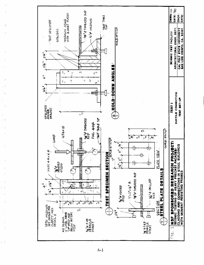
» I I-'
NOT&
', \-t
Ct..O
tlWN
t 4
:'tr
' No
T ~O
WN f
<'~ j
\~ II
::zY.
" W
WM
4·
+.,l
4· ,+
C
lAftl
TY
-hG
E:
'S
,
~T~I
I •• ~
~iI,p
r-!.~t7
___
~AD~P
#t JZ
.E-~ rz
. ;;~
~ ()
~
011,
'?TU~
/ W
Tf"
l:t.
~J~o~
-~ -
-'{j
'~ ea
ow tv
TTot
1 ~
no h
.. -
0TU1
7 ~
7Pe>
::.IM
fH
IINeH
ttt
~T ~~ ••
-+"
r~" f
~'1
I I'~J
,c" t r
o /~
()
{/
, I,
D r C D
-l'E
bT 0P~IMEN
~PkE~S
Ht?
I-Dt'W
N A~
WIl
li &j~T
PtII
:W7
~'/!
1> F
''''a.
F~H.ui,~
IN~E
:12-
T
~~ THF
&\~V
--P
t.'oL
.. ~~&
1 {>
I
(¥' I
~, I D
~
-~II4'T~ f
'4/
~'~
HO!-O
tWN
ctl
I,'
I'
,I ,JL
, ,k
cTiGi~ r
tf
,;,.,/4
f'~:
; r=e
fl-P-U
l.t
'N*~
T
m T
ES
T S
PE
CIM
EN
SB
CT
ION
\J
7
IIex
:ALe
-I~l
laIL
,,1I
r:2~~' f
~II"'H~O
EO l~:
~'~ -~
~--I~/
':fw
P
-"._
-~
--,
FJ
/ ll
lf-1
H,,~
~,e.
."
J
.
~i~
1'~
'I
~ ..
-p '
f' TH~VftI
/tOp
1--
--
\'
I)
\I,.,",~"·
,~p'm"".,,
J
~ -;:\ 'i-
-~
~",I'4
' ~ll.L.~t7~t~-
(. '1
-'-
HOl.E
: ~
~c. !J
oN
flML~
f0\S
TB
EL
PL
AT
. D
ET
AIL
S
\J..
) ~L.e;~~.ILo·
Fi q
. 11
NS
F S
PO
NS
OR
.D R
BS
.AR
CH
PR
o.J
ICT
I S
EIS
MIC
TE
ST
ING
OF
HE
AV
Y P
RE
CA
ST
FA
CA
DE
" C
LA
DD
ING
AN
D
CO
t,lN
EC
TIO
NS
IN
ST
EE
L B
UIL
DIN
GS
W~TH M
OM
EN
T A
ES
IST
ING
FR
AM
ES
"-T&?T~£
Top
[i:\
HO
LD
-DO
WN
AN
OL
•• I
W
~t:;
~JI"
,!oM
TE
ST
I
DU
CT
IL.
CO
NN
EC
TIO
N
na
T n
T-U
P
SE
ISM
IC T
.ST
FA
CIL
ITY
D
RW
N:
GIL
AR
CH
ITE
CT
UR
AL
EN
QR
. D
EP
T.
DA
TE
: 'Ye
7 C
AL
PO
LY
S
TA
T!
UN
IVE
RS
ITY
C
HC
K:
SA
N L
UIS
OB
ISP
O,
CA
. U
40
1
DA
TE:
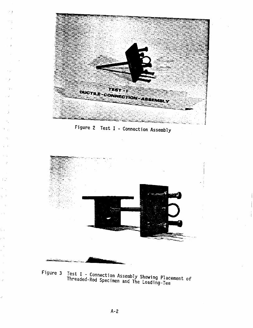
Figure 2 Test I - Connection Assembly
Figure 3 Test I - Connection Assembly Showing Placement of Threaded-Rod Specimen and The Loading-Tee
A-2
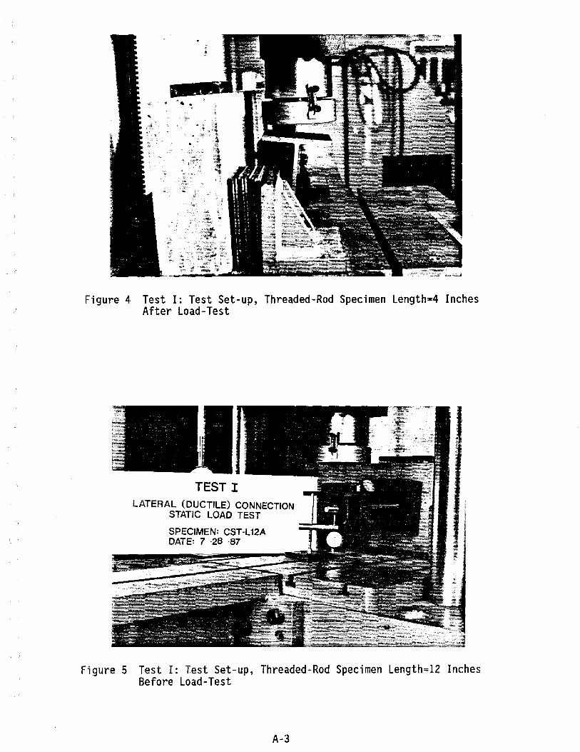
Figure 4 Test I: Test Set-up, Threaded-Rod Specimen Length=4 Inches After Load-Test
TEST I LATERAL (DUCTILE) CONNECTION
STATIC LOAD TEST
SPECIMEN: CST -L12A DATE: 7 -28 -87
Figure 5 Test I: Test Set-up, Threaded-Rod Specimen Length=12 Inches Before Load-Test
A-3
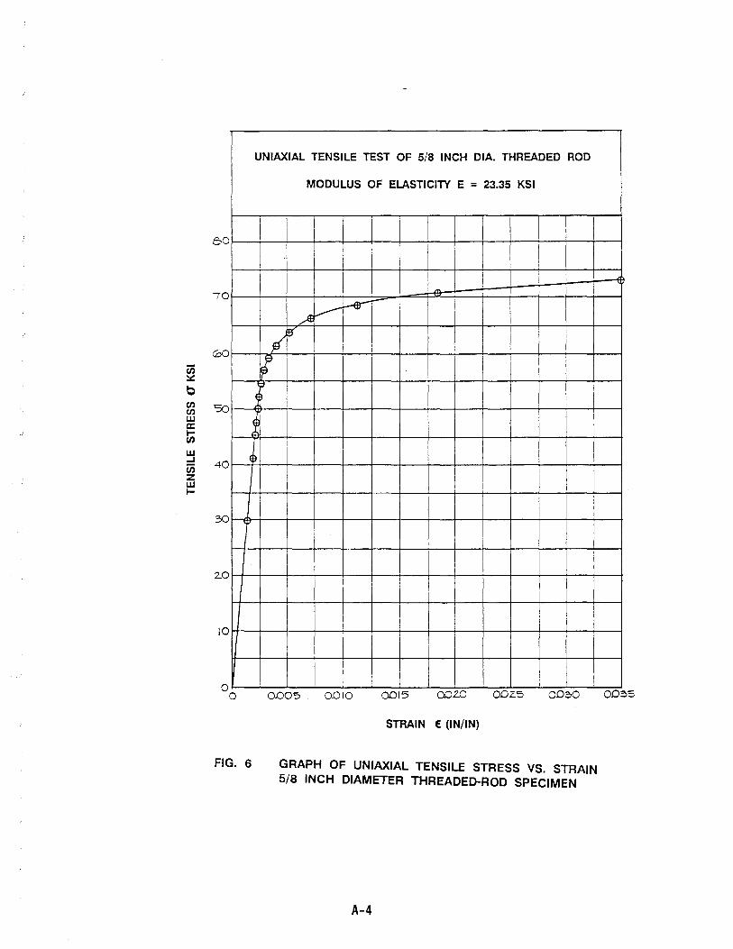
en ~
C en en w a: I-en w ...I en z w I-
60
70
00
50
40
30
2.0
10
o o
,
FIG. 6
UNIAXIAL TENSILE TEST OF 5/8 INCH DIA. THREADED ROD
MODULUS OF ELASTICITY E = 23.35 KSI
I I
I I
I !
I V :-e--I ~
I }If'~ II· I Il'
I ~
~ I
I 0.005. 0.010 0015 002.0 002.5 002>0
STRAIN (IN/IN)
GRAPH OF UNIAXIAL TENSILE STRESS VS. STRAIN 5/8 INCH DIAMETER THREADED-ROD SPECIMEN
A-4
002>5

en CD -J
0 ~ 0 -J
GOO I 1 1 I
I 500
-10 I ..A :..--:: ---= 400
1M ~ :..--- -J--Hil I ------ -~ 1"----<VI J t ,," I-W-
300
2.00
.ff /~ I I r I I
/,1/ J l I
-- -(1)--- TEST CST-L4A llA / p
rl I /; rl 1 I / /" • TEST CST-L4
! I I
.w I I J I ~ , ANALYTICAL MODEL
)' I /" I I I
100
f ~
o o 0.10 0.20 o.~ 0:4-0 0.50 0.00 070 0fY) 0.0/) 1.0 1.10 1.2.0
ROD DEFLECTION, INCHES
FIG. 7 LOAD VS. DISPLACEMENT CURVES THREADED-ROD LENGTH = 4 INCHES
A-5
-
--
I.:;:::
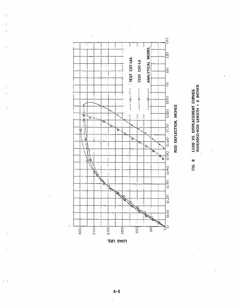
I
r f.-~
1 , S---,..,
II .j!
'-- w~ \- III
I~ '\
~ ~--~ ...
I f--.--L-
1
~ i I--+-
~ I
rl ~I
~ f--
o ~
I 1 1 1 ...J W e 0
< :E <0 <0
...J ...J ...J , .,:.. < I- U (J) (J)
~ u U l- I-(J) (J) < w w Z l- I- < - -
I
I
1 I I e
1 I I
~
'" I
'I ~ I I ['$., ~
~ $... e.,
. ...", ~ )r.,
"-...,
"
~ ""~ ~
o o N
, ~
~
o \!\
'S81 mf01
A-6
11l", ~
fa(,
I i I I
~ ""~ ~ ~ &.
o Q
I~
o l!\
o
q (J) w
(J)J: wu
0 >z a:-
6! 0
~<O U
(J) I- II W ZJ:
2 J: WI-U :ECI 0 Z wz
~
""e
uw z· :3...J 0 0 c..e r--: 1= (J)O 0 U -a:
W e, ...J .e
3 LI. (J)W W >e c eLi) 6 e <a: 0 OJ:
8 a: ...JI-
0 co
I
I I
0 ci '1: u:: 0
I
i I
0 {)
I I
6
0 "! 0
0 0
~
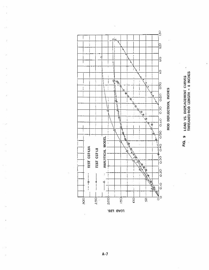
----
<t: 5 ~ (/) U l-(/) _ W
--
-
I-
I
I I f I I
(.
o ~
o tfI
'S81 aVOl
A-7
\ 0
o Q
(/) W ::I: U ~
Z o ~ ~ I.L. W a a o 0:
(/) W
(/)::I: WU fi:~ nco I- II Z::I: WI::Eel WZ UW :5...1 CoO (/)0 -0: 0, ,a
(/)w >0 aU) <t:o: O::I: ...II-
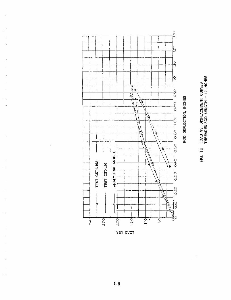
):>0
I co
en co
..J o c:x: o ..J
TE
ST
C
ST
-L10
-i
'I 1
'
! ,
I ~ool
-,-
T-
ANALYT
IC~L M
OD
EL
;---1
1,-I
11
1
I 11+
1---t1 '-
-+--
-1
1501
1
I I
I I
I I
I I
I ' ~I . ;4'
-r+~
'-l
I I
I --
ID-
I 1
---4
.
I ... ~.Y%'
i!
100
4--~~~~_~r-~--l--~~I~
50
i
i
+----
H !-i
O.b
O
0 -:T
O
0.5
0
0.'
00
1.
0 1.
10
1.2.
0 1.
30
RO
D
DE
FLE
CTI
ON
, IN
CH
ES
FIG
. 10
LO
AD
V
S.
DIS
PLA
CE
ME
NT
CU
RV
ES
TH
RE
AD
ED
-RO
D
LEN
GTH
=
10
INC
HE
S
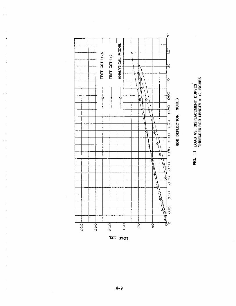
en >
~
I ID
C « 0 -
J
~OOrl ~--r--r~--+--+--
--I--1
JJ
I IJ
1
+--
-+--
--1
--
T'
I
I ~-~~
lJ--
-LJ-
J-L~
' __ --
(!)
---
Z50f--+-~~--4-~--~-+~
2.0
0
15
0
10
0
50
0 0
I .
. .
. .
---Il:r---
TE
ST
C
ST
-l1
2A
TE
ST
C
ST
-L 1
2
AN
ALY
TIC
AL
MO
DE
L
! I
.~T-+-~-~r-+-4-~--
l~
::;::-
y ...... -
'i--
-+-t
---1
---l
0.1
0
02
0
O.~O
Oft
-O
0.5
0
O.b
O
0-:
70
0
.00
0.
<::l0
1.
0
RO
D
DE
FL
EC
TIO
N,
INC
HE
S'
FIG
. 11
LO
AD
V
S.
DIS
PL
AC
EM
EN
T
CU
RV
ES
T
HR
EA
DE
D-R
OD
L
EN
GT
H
= 12
IN
CH
ES
1.10
1.
2.0
1.30
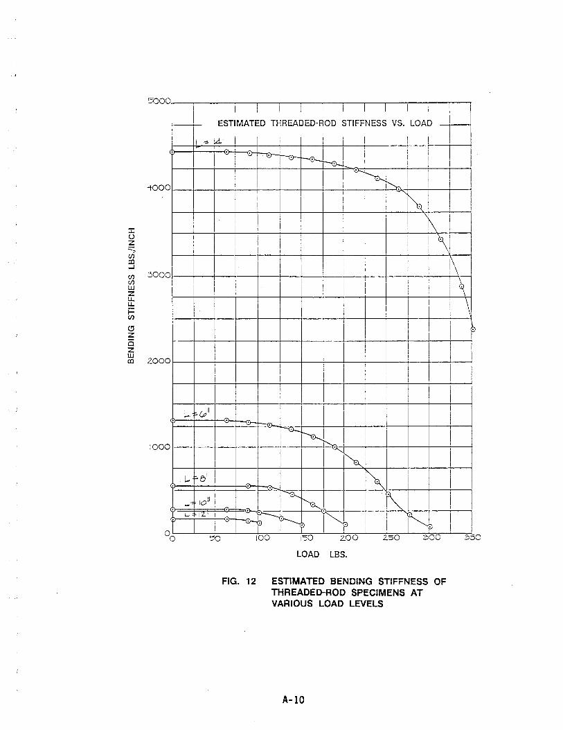
5000 I I I
II --
-tOO 0
I
::c () z .:::::: u:i m ....J
if) 3000 if) ill Z U. u. i= if)
(!J Z Ci Z ill m 2000
:.-. t" (P II
1000
L.. e/
-~ 10'1
'- 1'- 12."
I I I I I I I I I I I
I
ESTIMATED THREADED-ROD STIFFNESS VS. LOAD
4 11 I I I I I I I v '8 ~ I
""1!)--
I
I
'-. ~ I ~ i
I
I j I " I
! I I I~I I I
I
I I I I ~ I
I I I\J I I I I I I
I I i
I I I
I I I I
I
I i I I
t- I I ! I
I I I
I I i
I I
I
"" I I ~
~ I '" ~
I d- ~ r.-
~
" I ""'- '-.,.
-<:r-H~ i"p I N . I :> I 100 1'50 ~ LOO 2.50 ;::,00
LOAD LBS.
FIG. 12 ESTIMATED BENDING STIFFNESS OF THREADED-ROD SPECIMENS AT VARIOUS LOAD LEVELS
A-lO
!\ i~ I
I
I
I
I I
I
I
I I
I
I I
I
\ ~
'"
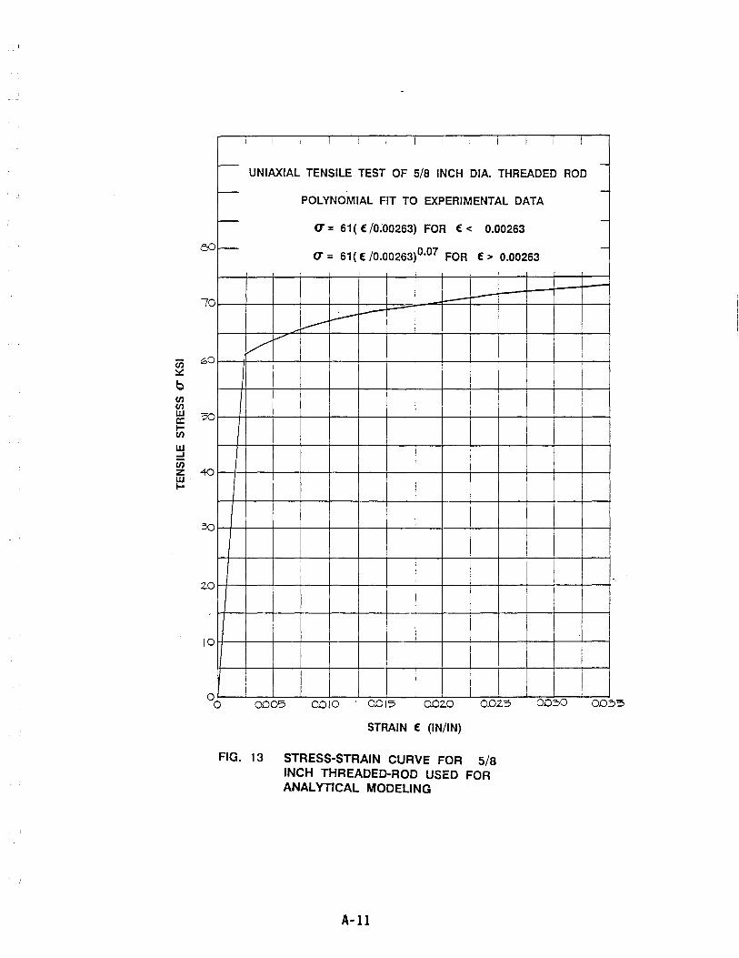
en ~
b CJ') CJ') w a: ICJ')
W ...J
en
70
z 40 W· I-
2.0
10
I I I I I I I I I I 1 1 1
f--UNIAXIAL TENSILE TEST OF 5/8 INCH DIA. THREADED ROD
f--POLYNOMIAL FIT TO EXPERIMENTAL DATA
r-U = 61 ( f /0:00263) FOR f < 0.00263
f--U = 61( f /0.00263)0.07 FOR f> 0.00263
- r---
~ !.----
l.--V
,./
I I I I
I I
I I I
1 I
I I
I I
I 0005 0010 0015 OD2.0 0.02.5 00:;,0
STRAIN f (IN/IN)
FIG. 13 STRESS-STRAIN CURVE FOR 5/8 INCH THREADED-ROD USED FOR ANALYTICAL MODELING
A-ll
I
I
-
-
-
-
-
00~5
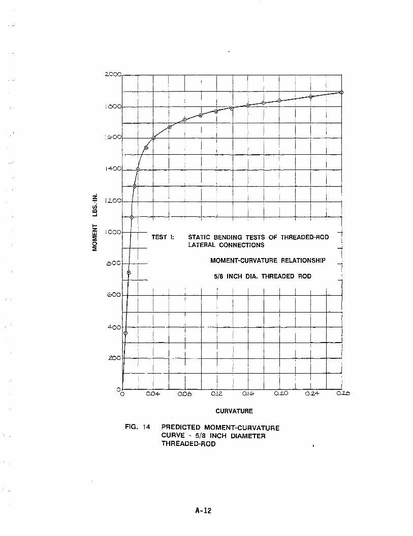
2000
1600
1000
1400
Z 12.00 ,
en III ...J
I-Z 1000 w :E 0 :E
000
000
400
zoo
\ \ \ I I I
! J- ~ L----· I
~ ~ I .--k ~
./ :r'
I I I I I I I
I I I I 1
I ...t. I
j I I r
I I I I I I
I I I I i
I i i .
I I I I I I I I ; I
TEST I: STATIC BENDING TESTS OF THREADED-ROD LATERAL CONNECTIONS
I MOMENT-CURVATURE RELATIONSHIP
. 5/8 INCH DIA. THREADED ROD
1
. I
I I I I
I
I I I
I I 0.0+ OOB 0.12. 0.10 0.2..0
CURVATURE
FIG. 14 PREDICTED MOMENT-CURVATURE CURVE - 5/8 INCH DIAMETER THREADED-ROD
A-12
I 0.2.4
-
-
-
-
O.Le
I
'.
J
J
-~
APPENDIX B TEST II
DRAWINGS OF TEST SET-UP AND TEST SPECIMEN
PHOTOGRAPHS
TIME HISTORY PLOTS
GRAPHS OF TEST RESULTS
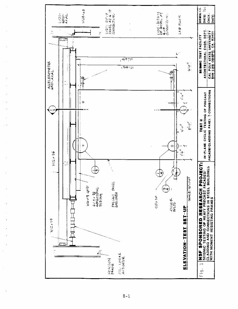
OJ
I I--'
, W
I: ,
,<
* ~<xfL'f.oH. T
O/'-
I; .
i W
I2 d
o
;_
" __
~flj
{7-AX'AL
' ___
__
_ b"
,," II ~ 1
n
n_
_
__
__
_ ~
( I
" "-
( \
, I
L'/
DT
t1~W
A~VIIL-
W--
4 ~"p
+
~·~111
-, td
E
.
WZ4f~8
r:-E"
4CTlu
N f=
-fA.M
f; TA)
t·H
./
Lit
lE"'
'::'
Aq(jAT{)~
/ I
~Tfl
LJC.
TUF,
4L
n.lBIN~
PI'-
t-%
T
f'tl-N
EL
5PfL
.IHE
N
./~t
CIO
" ".
It)
A:N
CH
cf
IVL-T~ ~~.~
t '"
" \
-'-.
:.../
IL
~fll
-
f I
.I ~
G. I
I E
LE
VA
TIO
N-T
ES
T S
ET
-UP
Fi g
. 1
~Lt: V
.;i:II
;:11o'
NS
F S
PO
NS
OR
eD
Re
•• A
RC
H P
RO
Je
CT
: S
EIS
MIC
TE
ST
ING
OF
HE
AV
Y P
RE
CA
ST
FA
CA
DE
SI
CL
AD
DIN
G A
ND
C
ON
NE
CT
ION
S I
N S
TE
EL
BU
ILD
ING
S
W,IT
H M
OM
EN
T R
ES
IST
ING
FR
AM
ES
r;,1
II
-/_
0
1) f
!?~Oll
TE
IT I
I IN
-PL
AN
E
CY
CL
IC
TE
ST
ING
O
F
PR
EC
AS
T
FA
CA
DI'
CL
AD
DIN
G P
AN
EL
~
CO
NN
EC
TIO
Ni
~
-.s ~II
~
_.,
-,
G
\0
J :::t
t:::
:1t '?
~o I
I
r,
I}
L'/D
T-
T'P
'f
PAN~L A
T c
t. /f
CU
N N
GG TI
[,He:.
.,
LYD
T -
!;vT
k't1
~F ~~
jE:L
.. Ir
f ~cF
C< ~NfCTI{ 'w
,
LA~
fl-t
v/Z
a ..
... e
TE
ST
FA
CIL
ITY
AR
CH
ITE
CT
UR
AL
EN
GR
. D
EP
T.
DR
WN
:GIL
DA
TE
: %
;/
CA
L P
OL
Y S
TA
TE
UN
IVE
RS
ITY
S
AN
L
UIS
OB
ISP
O.
CA
. U
40
1

OJ
I N
PF-E
-cA
0T
PANe
-L..
0PeC
IMef
./
lOA "
1 F·
4:;'
F~f1.I
'.UL~
1N0r
:tz.T
;' 1
\I6
i-'1
W0>
'-"1
(
W0
f.9
111111
\' ~~
,
i .'
11 ~ If
~'~6~~
"~_Ci
(. a
UlIi
(
/ 1
nr
~~Ii
1 f'
lAC
W
il\1l
l .I'"
J (1,
~>,-
4->'
-% 0T~GTUF>\L
TU~I
N6:j
Y.ill
I!'F
f0H
(?~
/ ck
.TAI
I...
2., TI+
I~ 5H
EET)
C;(~\I
1' T+
+F-&
\:PGD
fl
't?
,N
UT
0 W
iT H
y.; I
I II
\
c>VE
f<.0I
2.&
w4o
HEf
2-0
-210
U~ r
iO!..
!: 114
AN
9Lr:
L. 7"
"" >'-
Y:z-
;'.
'--~,,'If O
f'-\[.
.L.W
Ho
~E
CD DU
CT
ILE
C
ON
NE
CT
ION
-SE
CT
ION
I/:>
7"
;'LE
-·.'
3'~I
!.C'
1i
~
-l-
~
i i r J r 111
. I' .,'
't r
'0/
('
n
/ 'II"
--
6 V}J
.'
PR
:c,v
l P
AN
EL
6P
fClM
fN
I
t. I "
It; >
' 4-'"
~
0fi4
¥.T1
Jf,..
'i1...
Ti
J~IN
'1
/~IV
t..
4-f~
>'-Y
z -"
," Lvr
~
\\ t"
1:1 \
0~'11TH~AOW
:.?cD
NU
T0
't-ilT
ft J4.
.11
o 18
p..0
1 z.
;. \v
,¥ .. ,m~
·Fj
\ \
.lb
\ \
-2 ~ 11
4 rlO
L~ IN
AN£1
L&
I,l{ '"
III' Of
2"{I
."V~
r '-( l
.E.
([) D
UC
TIL
E CONNECTION-BOTTG~ ~
,I~~:
.. N
SF
SP
ON
SO
RE
D R
ES
EA
RC
H P
RO
JE
CT
: Fl
g ..
2is
EIS
MIC
T
ES
TIN
G
OF
H
EA
VY
P
RE
CA
ST
F
AC
AD
ES
! C
LA
DD
ING
A
ND
C
ON
NE
CT
ION
S IN
S
TE
EL
B
UIL
DIN
GS
W
ITH
MO
ME
NT
R
ES
IST
ING
F
RA
ME
S
TE
ST
II
~EISMIC
TE
ST
F
AC
ILIT
Y
DR
WN
: e
lL
IN-P
LA
NE
C
YC
LIC
T
ES
TIN
G
OF
P
RE
CA
ST
A
RC
HIT
EC
TU
RA
L E
NG
R.
DE
PT
. D
AT
E:
IYin
FA
CA
DE
/CL
AD
DIN
G P
AN
EL
+
CO
NN
EC
TIO
NS
C
AL
PO
LY
S
TA
TE
U
NIV
ER
SIT
Y
CH
CK
: S
AN
L
UIS
O
BIS
PO
, C
A.
93
40
1
DA
TE
:

tJ:)
I w
I 1_
~ ~
l' -
<tJ.2
"
1 1/
••• P~T
P)H
'L
-I\'\-
~I_ / 1~
ff
-4-?
-ON
T.
, \
0)
b /
~ •
···O?
••• ---
00
----
-~ II;
tt~[7Ep ?
rut»
W
-(\\------
o ~"
')=
Clol'-~O
-L.
<? >,2
.12" ~ -
? II
t..a-
I€j
---
L 6l
'4>'
<' "
4 -q
ti~N
!Ej
-----~-
°D
D
=
~
--
tij)1I1
> ~Da7 ~
1lJO~
n-~ IL
L/-
L fI"
""'?4
-4
II I£
tl 9
~
<:--I
;~t I [
11'" "
CO 1
--
--~'l? ~
ol..
T \l
itH
+
--
-= '<t * <S'
--t
\!"
;1
00
(1,
?;)v;)
.~ ~II
-t
--~I!
f f'\?
L1
WlT
tt ~t.lN!if;D
f:HD
CIO)
C~()
--(..~
fL.a>
P-
"'- ~
<:l
DO
()
~
o D
-. ~H
=---
--•
o.
'
o '"
D
<I'
p t!
DO
0 .r
Oi'
II II I
____
• a
.. __
___
-1\1
".-
---
J4~t
iJ 2n 1
Vlin
I I 1.-
CD BE
AR
ING
CO
NN
EC
TIO
N-S
EC
TIO
N
Ar
~l..
e: ~
II; !
LO
"
® BE
AR
ING
CO
NN
EC
TIO
N-P
LA
N
+
~l.E
:<?,
I.,L
O"
Fi g
. 3
I NS
F S
PO
NS
OR
ED
RE
SE
AR
CH
PR
OJE
CT
: I
TE
ST
II
. SE
ISM
IC T
ES
TIN
G
OF
HE
AV
Y P
RE
CA
ST
FA
CA
DE
SI
IN-P
LA
NE
C
YC
LIC
T
ES
TIN
G
OF
PR
EC
AS
T
CL
AD
DIN
G A
ND
C
ON
NE
CT
ION
S I
N S
TE
EL
BU
ILD
ING
S
fAC
AD
E/C
LA
DD
ING
PA
NE
L +
CO
NN
EC
TIO
NS
W
iTH
MO
ME
NT
RE
SIS
TIN
G F
RA
ME
S
,.
-
f2t'U
N\7
&D
5'14 I
i
I !ill
,f' A
eo.
g"
'-n
" ~~~
=] ".
. 0'1
f
.1
L j
fl.LV
/Z
·CH
AN
NE
L T
O L
AB
ED
FLO
OR
-C
ON
NE
CT
ION
f
~Ll';",,;ILoi
:SE
ISM
IC T
ES
T F
AC
ILIT
Y
DR
WN
: e
lL
AR
CH
ITE
CT
UR
AL
EN
GR
. D
EP
T.
DA
TE
: IV
I\7
CA
L P
OL
Y
ST
AT
E
UN
IVE
RS
ITY
C
HC
K:
SA
N L
UIS
OB
ISP
O,
CA
. 9
34
Q1
D
AT
E:
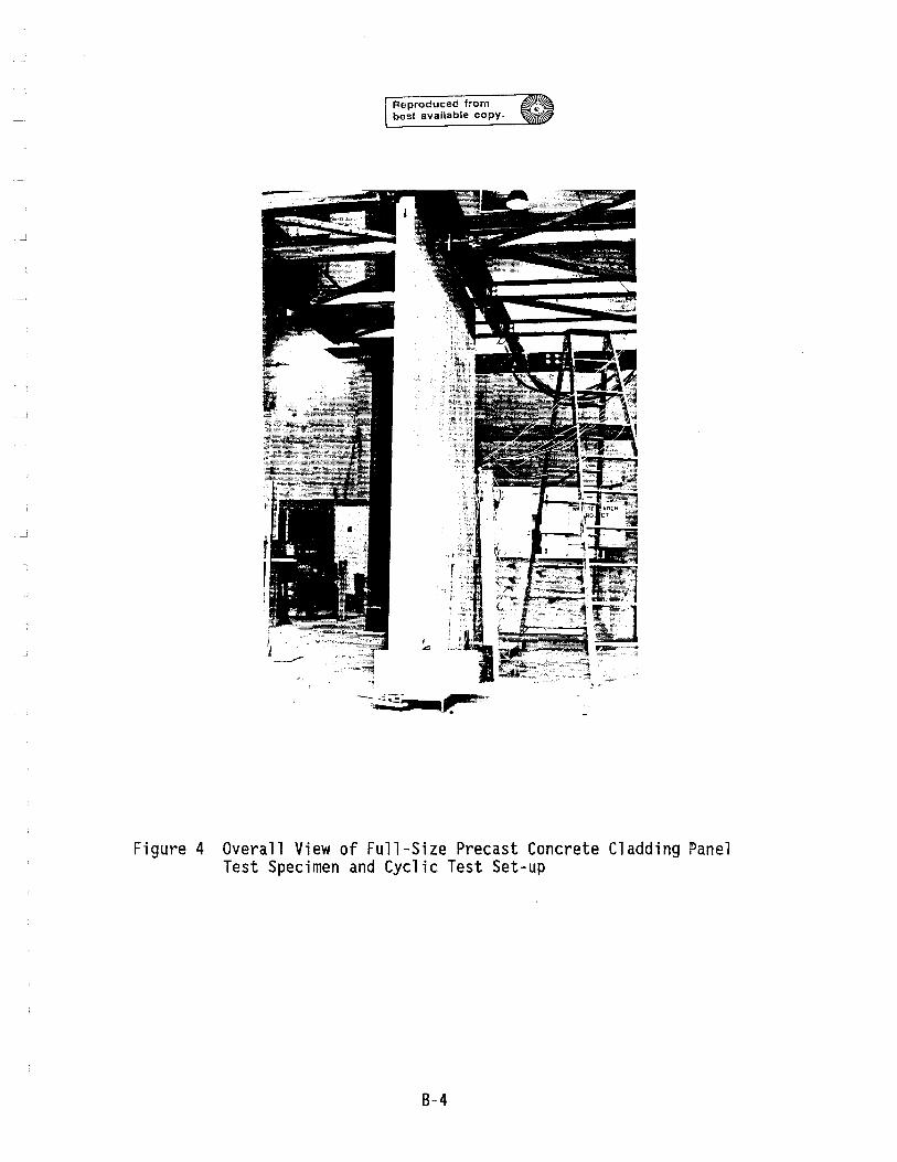
Reproduced from best available copy.
Figure 4 Overall View of Full-Size Precast Concrete Cladding Panel Test Specimen and Cyclic Test Set-up
8-4
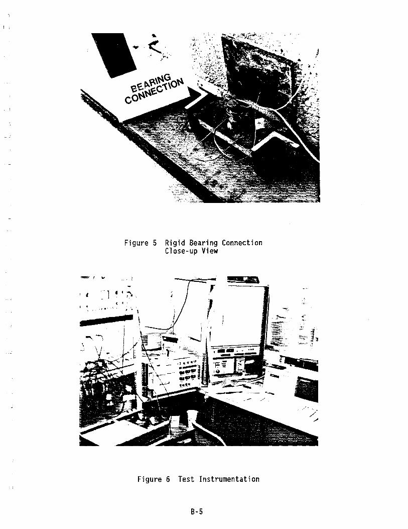
~.\ . , )' .. '. ~ ~';~~~ ~~r: . ,:. i. ' ... ~ ~
--"'"""., __ ~ ,I
~: i" -- .
Figure 5 Rigid Bearing Connection Close-up View
I , , I _-1";"\ , ( .
I • - -.=.J ~ '.' • ,- , ~.
a pF\
Figure 6 Test Instrumentation
B-5
.~. JJ
/ /
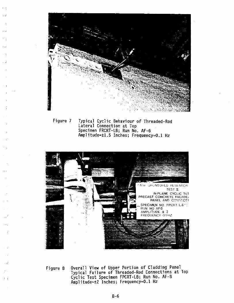
Figure 7 Typical Cyclic Behaviour of Threaded-Rod Lateral Connection at Top Specimen FRCRT-L8; Run No. AF-6 Amplitude=±l.S Inches; Frequency=O.l Hz
TEST II
INPLANE CYCLIC TE: PRECAST CONCRETE FACADE,
PANEL AND CONNECT\(
_~ SPECIMEN NO FPCRT· L 8 • RUN NO AF8 AMPLITUDE ± 2 FREOUENCY 01 HZ
Figure 8 Overall View of Upper Portion of Cladding Panel Typical Failure of Threaded-Rod Connections at Top Cyclic Test Specimen FPCRT-L8; Run No. AF-8 Amplitude=±2 Inches; Frequency=O.l Hz
B-6
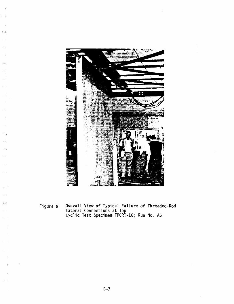
; j
Figure 9 Overall View of Typical Failure of Threaded-Rod Lateral Connections at Top Cyclic Test Specimen FPCRT-L6; Run No. A6
B-7
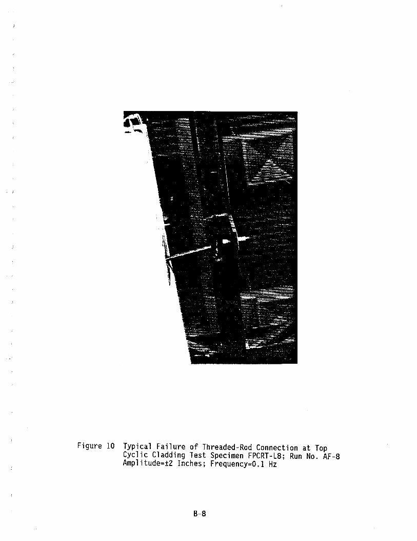
Figure 10 Typical Failure of Threaded-Rod Connection at Top Cyclic Cladding Test Specimen FPCRT-L8; Run No. AF-8 Amplitude=±2 Inches; Frequency=O.l Hz
8-8
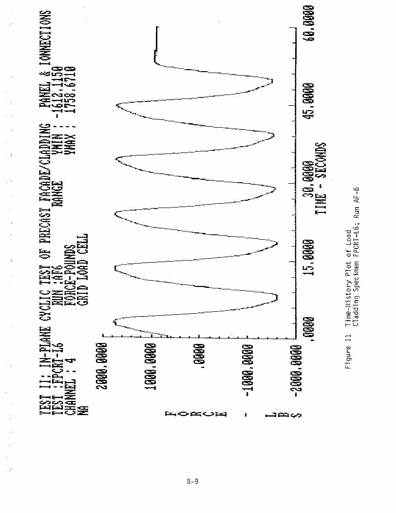
OJ I ~
TEST
II:
IN-PL
ANE
CYCL
IC TE
ST O
F PR
ECAS
T FA
CADE
/CLAD
DING
PANE
L &
IONNE
CTION
S TE
ST :
FPCR
T-L6
RUN
:AF6
RANG
E YH
IN :
-161
2,115
9 CH
ANNE
L: 4
FORC
E-POU
NDS
YMAX
: 17
58,67
19
NA 'GR
ID L
OAD
CELL
F o R
C
E
2099
,0090
1999
,9990
,9999
--10
00,00
00
,..',
1"
"1
r
/ 1\
/ \1
// II
/'1 /1\
'\
I
I I
I I
I !
\ ( "
\ I
\, I
\ /
\ I
\ I
V \
/ \. /
\)
\) \)
I,.,
J ~,
, j
L B
S
-2 99
9 ,99
99 L
I
l..-
L
I • _
_ L
__
~ •• _~ ...
. , I
_L.,
I ,L
L
J
,9990
15
,0099
30
,9000
45
,9900
69
,9900
TIM
E -
SECON
DS
Figu
re 1
1 T
ime-
His
tory
Plo
t of
Loa
d C
ladd
ing
Spec
imen
FP
CRT-
L6;
Run
AF-
6
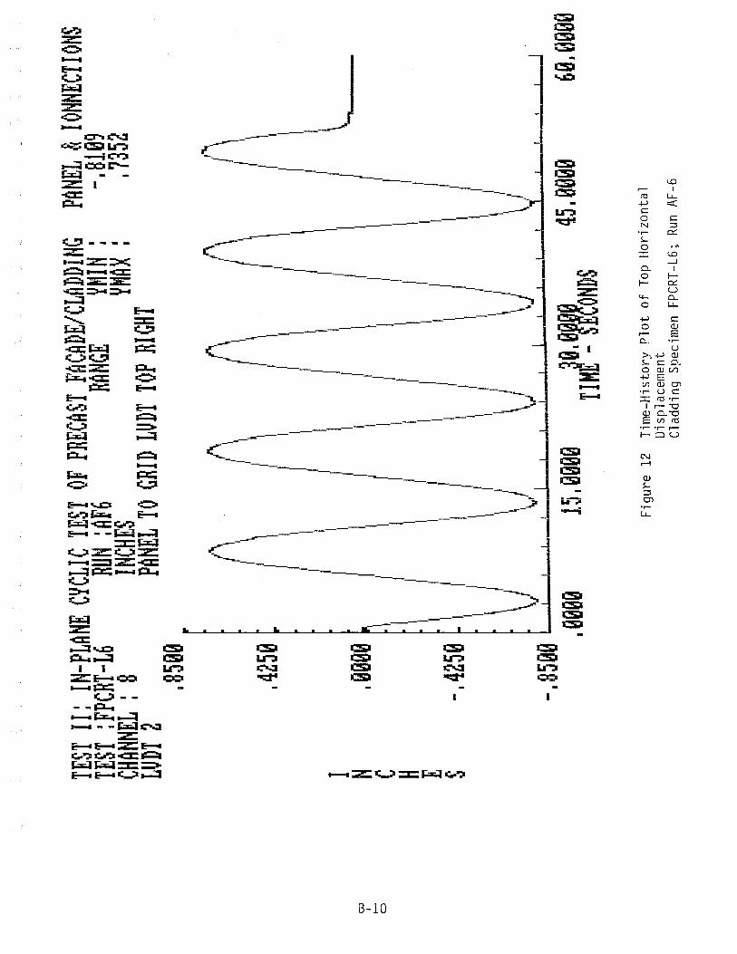
OJ
I I-'
C)
TEST
II:
IN-PL
ANE
CYCL
IC TE
ST O
F PR
ECAS
T FA
CADE
/CLAD
DING
PANE
L &
IONN
ECTIO
NS
TEST
:FP
CRT-L
6 RU
N :AF
6 RA
NGE
YHIN
: -.8
199
CHAN
NEL
: 8
INCHE
S YMA~ :
• 73
52
LUDT
2
PANE
L TO
GRID
LUD
r TO
P RIG
HT
I N
C
H
E
S
,8599
A
~
~
A
0, t\
",
/,
l\
I
" \
" ,
r '
t'
~ ,
,4259
l I
I i
1\ i
\ !
\ I
\ I
1\ I
III I
\ I
\ I
II
I II
I \
I II
II \
I Il
,9999
~ I
\ J
III i
\ I
\ !
"---
, I
I I
I I
I I
I I
" I
I I
I I
'I I'
1\ "
\ I
1\ I
\ I
I II
I I
-,42
59 ~
1\ I
I I
III I
1\ I
I\!
\ i
\. i
\ i
\! \ i
\)
\j
\J IJ
\/ -.
8599
I ,-'-
L_
I
! _
I 1
I 1
I _
L"-__
__
I -,~ ....
.... -
"--
-'--
-'--
....
.I
, 999
9 15
, 999
9 T1
H19~ 9
rl~OND
S 45
, 999
9 69
, '100
9
Fig
ure
12
Tim
e-H
isto
ry P
lot
of T
op
Hor
izon
tal
Dis
plac
emen
t C
ladd
ing
Spec
imen
FP
CR
T-L6
; Ru
n A
F-6
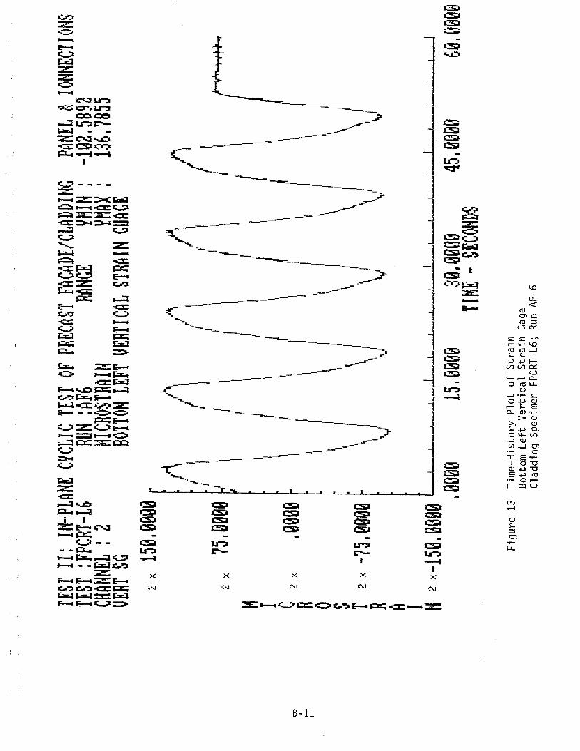
co
I I--'
I-
-'
TEST
II:
IN-PL
ANE
CYCL
IC TE
ST O
F PR
ECAS
T FA
CADE
/CLAD
DING
TEST
:FP
CRT-L
6 RU
N :AF
6 RA
NGE
YMIN
: CH
ANNE
L :
2 HIC
ROST
RAIN
YHAX
:
VERT
SG
BOTTO
M LE
FT V
ERTIC
AL S
TRAIN
GUA
GE
M
I
2 x
159.0
999
2 x
75.09
99
~ 2
x ,00
00
o S T 2
x -7
5. 99
09
R
A
.'J,
(\
'/\1
/ II
I I
I I
I II
I \
I I
I I
\ /
I I
I I
1/ I
III
\ /
II 'II
I I
\ I
\ I
\ I
\ i
\ I
I, I
\ I
\ I
'1/ I
~ I
\ J
I I,
I 'V
'I
I "J
\i
/'1 " I
J I 1
I " I \
I 1,
" ""l
J
PANE
L &
IONNE
CTION
S -19
2.589
2 13
6.785
5
'I
~
I I'
II I /
\ I'
I" I
'~ I
\)
I N 2
x -1
59. 9
009
I !..
I -
I .J
...._
I
I I
I ,.J
I
! !
~L.
I _
L.-
_I
! J
.9909
15
.9000
39
.0009
45
.0099
69
.9090
TIM
E -
SECON
DS
Fig
ure
13
Tim
e-H
isto
ry P
lot
of S
trai
n B
otto
m L
eft
Ver
tica
l S
trai
n G
age
Cla
ddin
g Sp
ecim
en
FPCR
T-L6
; Ru
n A
F-6
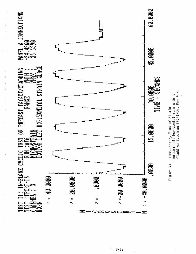
OJ I .......
N
TEST
II:
IN-PL
ANE
CYCL
IC TE
ST O
F PR
ECAS
T FA
CADE
/CLAD
DING
PANE
L &
IONN
ECTIO
NS
TEST
:FP
CRT-L
6 RU
N :A
F6
RANG
E YH
IN:
-24.4
260
CHAN
NEL:
3 MI
CROS
TRAIN
YH
AX:
36.63
99
HORR
BO
TTOM
LEFT
HOR
IZONT
TAL
STRA
IN G
UAGE
M
I
2 x
49.09
90
2 x
29.99
09
C
2 x
.9999
R
o S T
R
A
2 x-
20.99
09 ~
I' f I I I
I I
I-l,
\ r\
I I
/
I I
,I \
Jf, \ I.
( r
I N 2
x -49
. 909
9 L.
..~ _
_ ~ __
~_-L-_L_! -~--~
! I
! !
! ,
I ,_
, I _
J
.9900
15
.0000
39
.0900
45
.9900
60
.0090
T
H~E
.. SE
COND
S
Fig
ure
14
Tim
e-H
isto
ry P
Olot
of
Str
ain
B
otto
m
Lef
t H
oriz
onta
l S
trai
n G
age
Cla
ddin
g Sp
ecim
en
FPC
RT-
L6;
Run
AF-
6
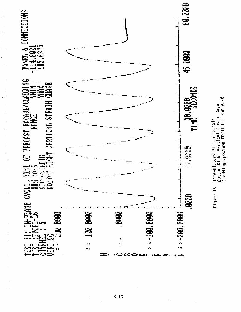
co
I I--'
W
TEST
II:
IN-PL
ANE
CYCL
IC TE
ST O
F PR
ECAS
T FA
CADE
/CLAD
DING
TEST
:FP
CRT-L
6 RU
N :oF
6 RA
NGE
YHIN
: PA
NEL
& IO
HNEC
TIONS
-11
4.892
1 18
5.637
5 CH
ANNE
L :
5 MI
Cn0S
TRAI
N YM
AX :
VE
RT S
G BO
TTON
nIGH
T VE
RTICA
L ST
RAIN
GUA
GE
H
I
2 x
200.9
00e
2 x
109.0
099
C
2 x
.0099
R
o S T 2
x -1
90. 9
099
R
A
." I~
I,
;1
I I. I
I ,I
I
I II
I I
, I
,I II
I ,;
I I
I \
I '1
I I
I "
, II \
,I
\ '
'.J
r\
I" f"l
,J
', ,I
I 1
' ,
J '
, /
l ~~
I '
J I
1 '
,r ,
r I
l I
l I
rr I
(II
I I
l I
I ii,'
I I
I ,I
I II
I I
I ":1
/ ...
11 "
\ I'
\ '
~ II
I I'
1 I
I
\'
I I'
i, I
I, I
\ I
\ I
~ I
\ l
1\ I
\ I
\J \" )
\ ;'
\ ".
\.
,.......
.---
I N 2
X -2
99. 9
000
l __ ~
__ ~ __
~_m,.!."
.• ",.,
J""_" .
.. I, •• _
_ '_,,,
,~,_l... _
_ L
.._
L 1
I.
l. _
_ L.
.-1
1 ,.
' ,
1 ,
. e90't
1 '::/;
I! ~~,~;l
~j~~ a0.
0~te0
45
. 0't0
0 6'~
. 00,j
,;
Fig
ure
15
TIME
-SE
COND
S
Tim
e-H
isto
ry P
lot
of
Str
ain
B
otto
m
Rig
ht
Ver
tica
l S
trai
n G
age
Cla
ddin
g Sp
ecim
en
FPC
RT-
L6;
Run
AF-
6
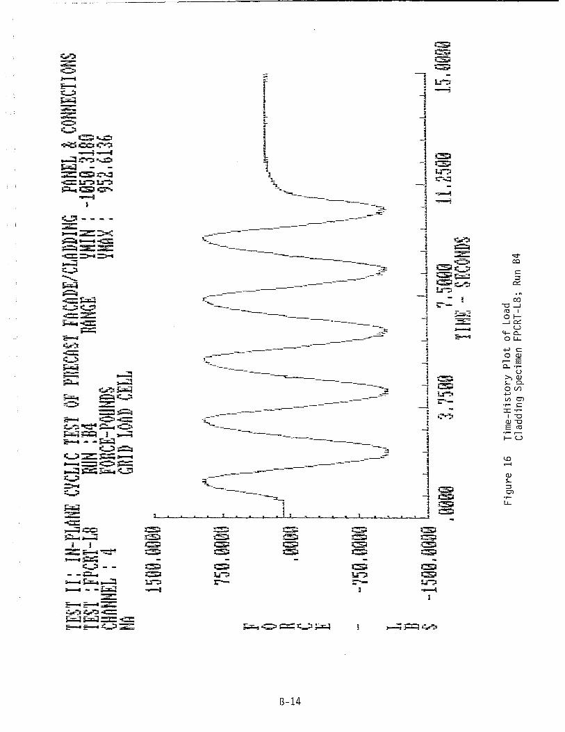
OJ , ........
+:>
TEST
II:
IN-PL
ANE
CYCL
IC TE
ST O
F PR
ECAS
T FA
CADE
/CLAD
DING
PANE
L &
CONN
ECTIO
NS
TEST
:FPCR
T-L8
RUN
:B4
RANG
E YH
IN : -
19Se
.3180
CH
ANNE
L: 4
FonCE
-POUN
DS
YHAX
: 95
2.613
6 NA
GRID
LOAD
CEL
L 15
e0.~
00e
750.
09cm
~1
0 n .0e
eo C
E
-wlS0
. ~~O
G
~
I~
rL
~ ~
.. ,
I I'
l ,
r ,
I I
I I
, I
I ,
,I 'I
' I
, I
I r
,
i 'I
,'I
1,1
'I I"
'I f
'I ,
I I
"
,I
i 1
,',
II 1
l 'I
" \
I' ill
I ,
/ ,
.' 1
,I,
'I
I I
, .....
. ,-!I'r~--~f'·'I""-U--r,\',
I I
) I
I ,
,LJ"
1 I
, I
I i
, 1
I I
' r
I I
I,
I, i
, 'I
1 I,
I 1
,I ,
I 1
" I
I 'I
I
1 I,
I I
I I
I I
I I
1 I,
I I
I I,
I I
I 'I
I I
I I,
I I
I, I
I I
,,'
'" I
I, l
I i
1 II
\ I
" I
~ ,
~
V
~
~
~ L
B
S
-15GG
.eegQ
L~_~_~L __
L __ ~
__ ~_~ __
_ L_~_~_~_~_~ __ L
_J .,~-~-~,~
. 900Q
3.
75~Q
7.S
G0@
11.25@
@ 15
.~~9
9 TIM
E -
SECON
DS
Figu
re 1
6 T
ime-
His
tory
Plo
t of
Loa
d C
ladd
ing
Spec
imen
FP
CRT-
L8;
Run
B4

O:J
I I-'
<.r
l
TEST
II:
IN-PL
ANE
CYCL
IC TE
ST O
F PR
ECAS
T FA
CADE
/CLAD
DING
TEST
:FPCR
T-L8
RUN
:B4
RANG
E YM
IH :
I)t flJ
Ill &
t~V'l~"
i' '!"ll
!~r]' I O
~:-I~;':
t~
1 "j
,.j
" .
ij II
, .. I"
111.1
l"nr.'6
..
. I J~
~,j
CHAN
NEL
: 8
INCHE
S YM
AX :
Lu
nT 2
PA
NEL
TO G
RID L
UDT
TOP
RIGHT
I 44
7~~
I r'~ C
u r !d S
["[mea
I \)
J I
,I ~"
~
A
~
~
A
i 'II i III
II
'" 1,1
\
II \
2 7 r. ~;
[
I II
II II
II II
I I
II I
I ,!
j ~
, I'
I, "
,I I
,I"
I'
I I
, I
,I
/ \
/ 1\
i 1\
I \ I
\\ 00
00 .
I
I I
I I
I I
I I
\" I,
. R
I
I I
I I
I I
I I
',,,,--
.,,,.,,,
",,,, ..
~,.,,, ' .,
,",""""
'.1'1
I I
I I
I I
I I
I
\1 i
II i
III I
\1 i
II I
,.. 27
5 ~;
I, I
I, I
I II
I II
II I
I ~,
II II
I, ,I
I, ,I
II'
I ,I
I I
,I
I,
II ,)
II ,
, II
I'
'I
V
V
V
V
V
...
I 5 5
~J ~l
L,.,.~
J." __
".t,""'","m
..J_",",,
,,,,,"I,,,
, •• ,,~,
,J,-"".,
",,,j,,,
,,~=,~..
I.~~~",,
",I'."m'
M .•. "I".,,
"~,,",l,",
","" ..... I
... 'mm~~
I."'""' .
• '~m'''~''
,,,,,,,",J
.-"",-"m~.
.J. .. ,,,,,,,
,,,,",,j,,.,
.,,,,,~',,,,
,,,",,,,.,,J
""" ""
',.,
,,
.i n
mum
3 75
rHl
r, ~ o~
~.
11 til
'· Oil
1,"'"
l]
n
I ~,'~
J~:'~,'
,; I ~n:
' j
.,.,
~:, I
",,,"
, /'8
\) ~;JP
O t:L
~'n(l
b~f
T H1
E "~
S' L:ON
nS
Fig
ure
17
Tim
e-H
isto
ry P
lot
of T
op
Hor
izon
tal
Dis
plac
emen
t C
ladd
ing
Spec
imen
FP
CR
T-L8
; Ru
n B4

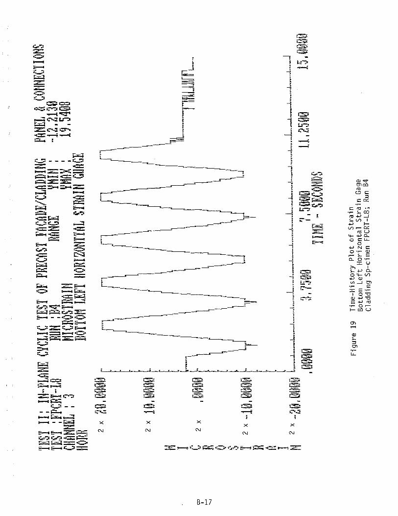
co
I ........
'-J
TEST
II:
IN-PL
ANE
CYCL
IC TE
ST O
F PR
ECAS
T FA
CADE
/CLAD
DING
PANE
L &
CONN
ECTIO
NS
TEST
:FPCR
T-L8
RUN :
B4
RANG
E YH
IN:
-12.21
30
CHAN
NEL:
3 MI
CHOS
TRAIN
YM
AX:
19.54
08
HORR
BO
TTOM
LEFT
HOR
IZONT
TAL
STRA
IN GU
ACE
N
I C
H o S T
R
n
2 x
2 e ,00
00 r"
f"l
n
rl r'~
r""
l f
~ l\
I I
I
I 1
\ 2
x 1 0
, 000
0 ~
I \
1 /
II \
f \
I I
I I
\ I
I ,.-
", I
II I
I I
\ I
11L"
_'_11
I
II II I
II \
\ I
2 x
-10,
0000
~ Lf
l'lli LJ
\r IJ
~ 2
x _ 2
0 ,00
00 l
~_.J. _
_ 'L..
""_
l...
..,.
L".
,,,"
,_""
l.-_
,.I.
._..
.L_
,_L
.. ...
J,..
.,.-
J_..
..J-
_,.
J_,_
L..
..J,
---J
.--.
L..
_,-
,-_
J
,0~0
9 31
7509
7.5
00e
11.25
80
15.00
00
Fi g
ure
19
T U11
E: ,Q
S E
cOt'm
S
Tim
e-H
isto
ry P
lot
of S
trai
n
Bot
tom
L
eft
Hor
izon
tal
Str
ain
Gag
e C
ladd
ing
Sp-c
imen
FP
CR
T-L8
; Ru
n B4
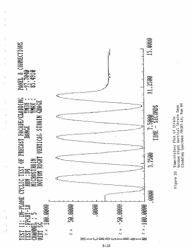
TEST
II:
IN-PL
ANE
CYCL
IC TE
ST O
F PR
ECAS
T FA
CADE
/CLAD
DING
TEST
:FPCR
T-L8
RUN
:B4
RANG
E YH
IN :
CHAN
NEL
: 5
MICR
OSTR
AIN
YMAX
:
VERT
SG
BOTTO
M RIG
HT V
ERTIC
AL S
TRAIN
GUn
CE
2 x
10(L
~000
A
~
~ ~
~ I
I ,
, r I
I
1 (.
,
. l',
{I,
(I,
/',
/1
1
2 x
50 ,0
000
[ I'
II I
II II I
i I
I' I
I I
" I
I ,I
,I,
t:; l
II I
I i
I I
I I
I I
'I
I I
I I
I ,I
,
C
,~000
II I
I I
I I
I I
I II PA
NEL
& CO
NNEC
TIONS
-97
.7040
85
.4910
n I
I I
I, I
II I
II I
\ 'fO
..... ,
.. ,
I I
I I
' II
I I
\ I-'
" I
I ~'"
00
'I
I 'I
, ,
I 'I
,I
'"·-
j'rr
----
"' ....
. ~~LI._
8 'I
I I
I I'
I I
I I
T 2
x -5
'L0e9
{1..
II II
I",
'I'
"II
',I
R
I I
I "
, I
I ,
,I
I ,I
,I
II I
o I
I 'I
',
I
I'
I I
i'I I'
I I
I '
, I
I I
I I
' I
I '.
" 'I
, I,
" 'I.
' I"
II
tJ 2
x 1 o
n r.
Hli
ln
1.",1
t"J J
\~,'
'orl
,.,,,
L j
" ,m
,
• II:}
10. f
J II:}
'0 IV
~_"
"J.m""
""'" ..
I._ ... m
m'""I,,,
m''''''''m
",J..".,,,
,.,,,~
"_,,.
_I...
.."' •.
'".J.:
._"'..
Jm"_~_
I,m.~n
"~" """
''""'I".
"'''_'''
'''''I..
.._M~I.,
,,..,'''
'''''. ,
1.,.""
"'""" .
... ,, .
. ~ .. ""
_t"',,
"''''_
I_'''=
.~I,'_
m_..J-
-
I ~l~
j~'0
3. li5
00
7 I 5~J
~~t
11. l:
5"H
15 I 0
0'1~;
T I ru
: .... ~
EGON
mS
Fig
ure
20
Tim
e-H
isto
ry P
lot
of S
trai
n
Bot
tom
Rig
ht V
erti
cal
Str
ain
Gag
e C
ladd
ing
Spec
imen
FP
CR
T-L8
; Ru
n B4
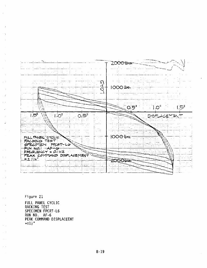
L~
. . ~ _ .. _--------------- - .. ----~--- "-- -.
n --_.-'-" -.-___ .. <C
;-.-~_~~ 3
t\\l'
Figure 21
FULL PANEL CYCLIC RACKING TEST SPECIMEN FPCRT-L6 RUN NO. AF-6 PEAK COMMAND DISPLACEENT =±H"
8-19
~--r~:?j~f~u=~~~ .• "I .- < , • •
••• j • • ••• -. ; •
]- r-- ;
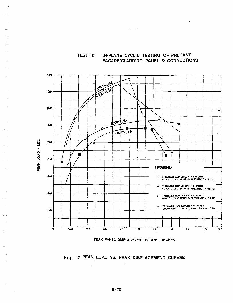
lOX)
I~
en (Ott! !Xl ..J
C ~ 0 f:I)() ..J
~ ~ UJ a.
~QO
TEST II:
~ #
!J V
1/ IV
II ~ ,/
...< r / L /-
II / i' ~ d /
V /
/ e
IN-PLANE CYCLIC TESTING OF PRECAST FACADE/CLADDING PANEL & CONNECTIONS
./' ............... \
~~ ~ /' ~ \ ~~
.,.~
~\ ~~ '\ "'-"-
~~ ~ 1\ ~ - \. '" ~ / ~ "'" ~ ~ ~ ~- ti -l.e ~ '\ I'\.
/' 1\\ \ .~
'm •
LEGEND
• TliREADED ROO LENGTH • 6 INCHES BlOCK CYCUC TESTS @ FREQUENCY • 0.' Hz
.. TliREADED ROO LENGTli • 6 INCHES BlOCK CYCUC TESTS @ FREQUENCY • 0.5 Hz
o TliREADED ROO LENGTli • 8 INCHES BlOCK CYCUC TESTS @ FREQUENCY • 0.' Hz
TliREADED ROO LENGTli • 8 INCHES
-
-
---
EB BlOCK CYCUC TESTS @ FReQUENCY • 0.5 Hz _
_I , ,
o.~ a.+ 0,8 /,0 I.~ 1.+ (." I.e, 'Z.o
PEAK PANEL DISPLACEMENT @ TOP - INCHES
Fi g. 22 PEAK LOAD VS. PEAK DISPLACEMENT CURVES
8-20

o
i I~ g
(
~
~l 0 1:
[~ 0
1'1 -: 0 1" 'l --~ II
en CJ ~ (j:J Z N 0 I-r- 0 I~ 0 i= 1\ ~ 0 U ~ ~ W Z ~
I~ Z :J i'-0 G 0 U
~ N I~ 0 t;~ 1* I~ 0 e:('-I
Ii Itt UW IS WZ 'r a::e:( '-.l 0
~~ Iii. ~ .~~ g Ll.CJ @. Oz <l:) <{)
CJc ~~ ~ j ~ tf'\ Cl zC w
i=:3 0 ~ enU ~\\ 0 c: W_ ~ 0 g I-W g c
~\ ,\
'~ Ue:( a: -U ~ + Q -Ie:( 0 ~Ll. ~ 1\ \\ g U w
~ Wtij
\\ ,\ <l Za::
"" :3u 0 ~z 0 '0
.~ \E 2:u c5 1\
= ti \',\ c5 I-
~ \\ 8 en W
~ 1\ f- l-I-
~ " ~\ ~ 6 ~ ~ ~
0 0
~ ~ 0 \5l .0 T 'N 0 d c:i c:i 0 .0 c:i lHl:ll3M 13NII'd/SNOIJ.03NNOO
OO!l-030'il'3!1H.l :lO 30N\'lSIS3!1 30!lO:l lW31\'1 >I'iI'3d MId
NSF SPONSORED RESEARCH PROJECT SEISMIC TESTING OF PRECAST CONCRETE FACADES/CLADDING & CONNECTIONS
FIG. 23 PEAK LATERAL FORCE RESISTANCE SEISMIC TEST FACIUlY
OF THREADED-ROD ARCHITECTURAL ENGINEERING DEPARTMENT CAL POLY STATE UNIVERSITY
LATERAL CONNECTIONS VS. DRIFT SAN LUIS OBISPO, CA 93407 DRAWN __ DATE __ CHECKED __ DATE __
B-21
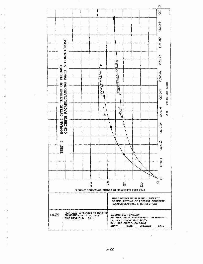
o I
- - i
I 8 I
I IS"' 0
I g I
I CJ) I 6)
Z 0 0 0 1= (j U w Z Z r-. 0 0 U . 3
I-~ IN- N I
CIJ «..J - (J I
UW ~ 'i!-I ~ wz I CI:« It 0
c..c.. ~ 2: I 0
LL~ 2 Ill. (j III "::l
f-
Oz J:
~ i <!I
~C w
li\ J:
ZC >-1=:3 . 0 c:
0 Q f-CJ)u 0 CJ) w_ fr" I-W
U~ -t--
1\ a: Q
::iU 2: "'t" U « _. -
~\ 0
~ >LL
~I\ g U w <l
wI-ZW ~\
-
:35 ~ ~ c..Z -- 0 '0 _\ 1\ § ~u
-- -\
I~ - 1\ ~ -I- \
0 CIJ 8 W I- ~
~ \ -0
~ ~ 0 a
~ ~ 0
0 ll) ~ l!I 0
0 t--N
~
% 31~NV NOl103NNOO ~Nn:IV38 01 3~!:IVHO!:lnS aV01 )lV3d
NSF SPONSORED RESEARCH PROJECT SEISMIC TESTING OF PRECAST CONCRETE FACADES/CLADDING & CONNECTIONS
FIG_24 PEAK LOAD SURCHARGE TO BEARING CONNECTION ANGLE VS. DRIFT SEISMIC TEST FACIUTY TEST FREQUENCY = 0.1 Hz ARCHITECTURAL ENGINEERING DEPARTMENT
CAL POLY STATE UNIVERSITY SAN LUIS OBISPO. CA 93407 DRAWN -- DATE __ CHECKED __ DATE __
9-22

o
J Q 0
,
Cl' I 0
N [. I 8
:r. 11\ ~ GJ ~ ! IS' 0
<:) 0 CJ)
~ d Z II 0 :I r i= --
~
~ () C r:--w
0 z _. ..E. Q z i ~ 0 0 \I-() J ,
t;o/S \ ~ c:(..J 0 ()W
[~ Q wz 0 a:c:(
a. a. .... :I: Ll.(!J
I~ " Oz 1- If\ iii 0 :I:
(!JC ,;.
l\ () g a: ZC 0 II .... i=~ (/) I .J
~ CJ)() w_ ~\ ? a: I-W
"¢" c C
0 ()c:(
\ Q -() ~
..Jc:( 0 ~Ll. <l
()w -\
-r· -
wI- 1\ ~ ZW 1\ 0 ~5
~ 1 Q a.z 0 '0 ~() \. \ I ~
0 = \ 1\ 8 I-CJ) W -
\ I-
~ -1"\ 0
~ \ g
~ k 0 0 U} 8
If) 0 l"- N 0
% 31tlNII NOI~3NNO::l <lNll:I\f3B 01 3<ll:lIlH::Il:IOS 01101 ){\f3d
NSF SPONSORED RESEARCH PROJECT SEISMIC TESTING OF PRECAST CONCRETE FACADES/CLADDING & CONNECTIONS
FIG. 25 SEISMIC TEST FACILITY PEAK LOAD SURCHARGE TO BEARING ARCHITECTURAL ENGINEERING DEPARTMENT CONNECTION ANGLE VS. DRIFT
CAL POLY STATE UNIVERSITY TEST FREQUENCY = 0.5 Hz
SAN LUIS OBISPO, CA 93407 DRAWN __ DATE __ CHECKED __ DATE __
B-23
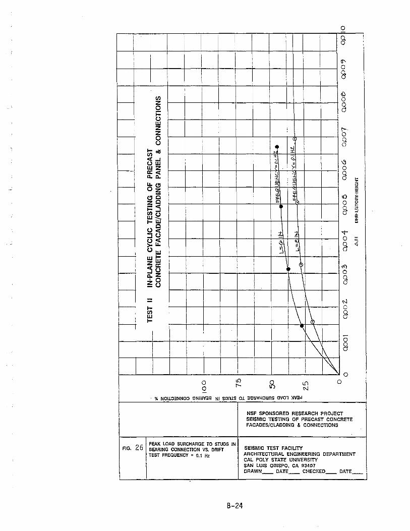
o
1
I I
I I
§ I i
I Ii' 0
8 i
en ~ 0
-I z 0 0 (j i=
---l U w Z !'-
- Z 0 0 . Q U
~ 0
I-~ N
- ::t: en :t: «...I ~ uw <'> " ~
l------j wz 1\ T- o 0:< v ~ § I a. a. ili ~ i f-
Ll.CJ :J:
-", :,; (!)
Oz i w
~ :J:
CJc to >-ZC
a: f--- . 0 0
~::s f-
0. '" enu a ~ I----
w_ e: I-W c
u~ "1- "2 -.r :JU f---~it ~
0 ~ ~ 8 <l
U w ~\ J f--- wI- \ ZW .) :)5 ~
t<)
- 0 a. Z \ Q '0
1\ ~u a -
\ - \ ~ -- I-
~ 0
en 8 W I-- ,
f\\ -0
'\ [\ g , 0
0 I.!}
~ If) 0 0 l"- N -
'Yo NOI1::l3NNO:> ~NII:I'V'38 NI SQIUS 01 3~I:I\1H:>l:InS Q\101 )I'V'3d
NSF SPONSORED RESEARCH PROJECT SEISMIC TESnNG OF PRECAST CONCRETE FACADES/CLADDING & CONNEcnONS
FIG. 26 PEAK LOAD SURCHARGE TO STUDS IN BEARING CONNECTION VS. DRIFT SEISMIC TEST FACIUTY
TEST FREQUENCY = 0.1 Hz ARCHITECTURAL ENGINEERING DEPARTMENT CAL POLY STATE UNIVERSITY SAN LUIS OBISPO, CA 93407 DRAWN __ DATE __ CHECKED __ DATE __
B-24
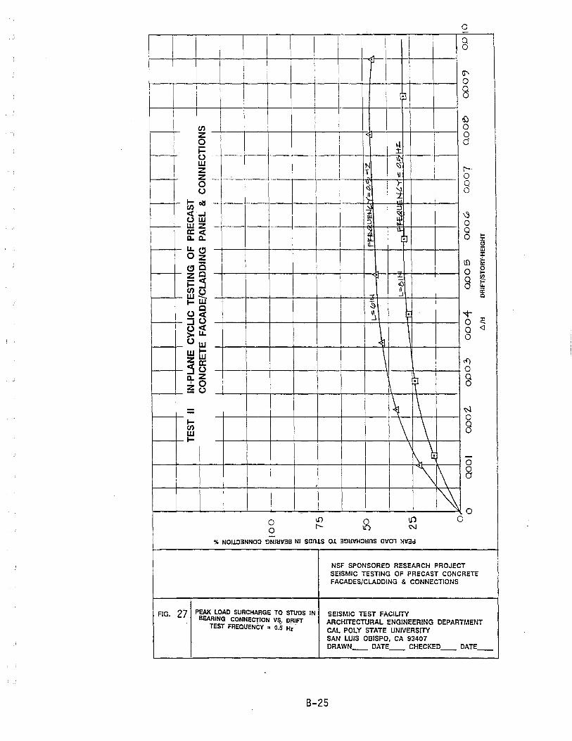
o ..
I I I I \ \ J I K-i-..c
Q 0
I ;1-
I
,
\l" 0
~ g
I I 6:)
en 0 Z .
I 0
I 0 \.l 0 i= :t. I .- t--U . -. .----
I ~ I w N r--I z T II 0 I Z .----
~~L ---r--- ---I I~ ~ Q
I 0
0 U ~ :t.
I-~
I~ ~ en ~ ct..J
OW :J ~ 0 wz -- _.- -- --.- ----.
l I ~ Q a:ct 0 ~ a. a. I~ (!I I W Ll.(!I
J: Oz If) >-a:
(!IC 0 ~ ZC . -= g ~ i=:3 () II a: enu
~ ..I Q w_ I-W
~ C \1 . T Oct .J
0 ~ :::IU <l ~~ Q
~ 0 Ow WI- \ ZW ~ :55 0 -
Q a.Z
J '0 0 ~o
- ~ - - .1--- 0 I- 8 en W I-
\1\ \ -0
\J\ 0 a
,
~ 0 -
0 U)
~ U1 0
r-- ~ 0 % NOl103NNOO ElNiIlV3B NI sants 0.1 3ElllVHOllns aVOl >lV3d
NSF SPONSORED RESEARCH PROJECT SEISMIC TESTING OF PRECAST CONCRETE FACADES/CLADDING & CONNECTIONS
FIG. 27 PEAl( LOAD SURCHARGE TO STUDS IN SEISMIC TEST FACIUTY BEARING CONNECTION VS. DRIFT ARCHITECTURAL ENGINEERING DEPARTMENT
TEST FREQUENCY " 0.5 HZ-CAL POLY STATE UNIVERSITY SAN LUIS OBISPO, CA 93407 DRAWN __ DATE __ CHECKED __ DATE __
8-25
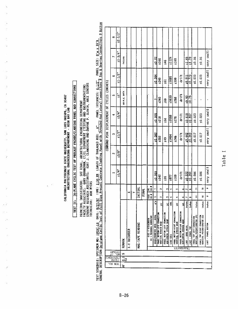
OJ
I N
O'l
CALI
FORN
IA P
OLYT
ECHN
IC S
TATE
UNI
VERS
ITY,
SA
N LU
IS O
BISP
O,
CA 9
3407
AR
CHIT
ECTU
RAL
ENGI
NEER
ING
DEPA
RTM
ENT
-HI
GH B
AY L
AB
TEST
II:
IN
-PLA
NE C
YCLI
C TE
ST O
F PR
ECAS
T FA
CADE
/CLA
DDIN
G PA
NEL
AND
CONN
ECTI
ONS
-J
PRIN
CIPA
L IN
VEST
IGAT
OR:
SAT
RIHA
L,
ARCH
ITEC
TURA
L EN
GINE
ERIN
G DE
PART
MEN
T FA
CULT
Y AS
SOCI
ATE:
GA
RY G
RANN
EMAN
, ET
/EL
DEPA
RTM
ENT
(TES
TING
AND
INS
TRUM
ENTA
TION
) ST
UDEN
T RE
SEAR
CH A
SSIS
TANT
S:
KURT
J.
CLAN
DENI
NG A
ND D
WAYN
E P.
SL
AVIN
, AR
CE S
ENIO
RS
TECH
NICI
AN:
BOB
MYER
S
TEST
SCH
EDUL
E:
SPEC
IMEN
NO:
fP
CRT-
L6
DATE
: ~
TIM
E: ~
LENG
TH O
f TH
READ
ED R
OD:
___ 6_
" ___
PA
NEL
THIC
KNES
S: ~
PANE
L SI
ZE:
8'w
x 1
0'h
GENE
RAL
DES
CR
IPTI
ON
:In-p
lane
Cyc
lic T
est
of F
yll
Size
pre
cast
Con
cret
e C
ladd
ing
Pane
l w
ith T
hrea
ded-
Rod
Lat
eral
C
onne
ctio
ns @
Top
& B
earin
g C
onne
ctio
ns @
Bot
tom
[,
COMM
AND
PEAK
DIS
PLAC
EMEN
T OF
CYC
LES
(INCH
ES)
. z
~ CI
~ ~(J)
w::O
ow
I
2 3
4 5
6 7
8 z
Xo
0-1
·U
:J H~ 0
>-<
±l/4
" ±3
/S"
±1/2
" ±3
/4"
±I"
±I-
l/2"
±1
-3/4
" ±2
-1/2
" "" ~~ z
u
Af
0.1
Hz
5 RE
MARK
NO
P.C
. DA
TA
FAIL
URE
X-Y
RECO
RDER
X
Y
I
MAG
-TAP
E RE
ADIN
G IN
ITIA
L FI
NAL
VIS
I •
VIS
ICal
DE
R
VIS
I PC
PC
•
PeRS
ON
AL
ClJI
PUTE
R
CH
II CH
II
ACC
ELER
!J4ET
ER
GR ID
-
AX
IAL
U's
1
1 to
.003
to
.002
±O
.OOl
i ?
to.O
O4
+0.0
2 PA
NEL
BOTT
CJI
LEFT
C
ON
NEC
TlIJ
i ±1
42
t202
±2
1S
±240
±2
40
±I60
V
ERTI
CAL
STRA
IN
GAGE
11
£ 2
2
PANE
L BO
TTCJ
I LE
FT
CO
NN
ECTl
IJi
±35
±49
±56
±60
t61
t46
HO
RIZO
NTA
L ST
RAIN
GA
GE
11£
3 3
LOAD
CE
LL
LSS
. 4
4 ±9
77
±140
4 ±I
5B8
±163
0 ±1
6S5
t112
4
"" PA
NEL
BOTT
CJI
RIG
HT
CIJiN
ECTI
ON
tl
69
t246
±2
78
t2SS
t3
00
±IBO
w
V
ERTI
CAL
STRA
IN
GAGE
11
£ 5
5 ()
::0
PANE
L BO
TTCJ
I RI
GH
T C
IJiN
ECTI
ON
d
rift
d
rift
d
rift
d
rift
d
rift
A
l£
U
l H
ORI
ZON
TAL
STRA
IN
GAGE
6
6 z ;:1
LVOT
-
GRI
D
AX
IAL
inch
es
7 7
to.2
22
±0.4
42
to F
ilQ
+O.Q
O +0
. Qll
tl 6
5 E-
' LV
OT
-PA
NEL
Ta>
inch
es
8 8
to .1
61
to.3
43
±0.5
57
to.7
5 to
.773
±
l. 70
PA
NEL
TOP
LEFT
CO
NN
ECTI
ON
±0
.006
±0
.017
to
.023
-
±0.0
33
to.0
6 V
ERTI
CAL
POTE
NTI
<JIE
TER
(P)
inch
es
11
11
PANE
L TO
P RI
GH
T CO
NN
ECTI
ON
±0
.006
V
ERTI
CAL
POTE
NTI
<JIE
TER
(G)
inch
es
10
10
±O.O
l7
±0.0
23
-±0
.033
to
.06
LVOT
-
PANE
L SO
TTCJ
I in
ches
9
9 ve
ry s
mal
l ve
ry s
mal
l ve
ry s
mal
l -
very
sm
all
very
sm
all
-
Tab
le
I

OJ I N
"'-J
CALI
FORN
IA P
OLYT
ECHN
IC S
TATE
UNI
VERS
ITY,
SA
N LU
IS O
BISP
O, C
A 93
407
ARCH
ITEC
TURA
L EN
GINE
ERIN
G DE
PART
MEN
T -
HIGH
BAY
LAB
TEST
I I:
IN
-PLA
NE C
YCL
IfTES
T OF
PREc
ASTF
ACAD
E/CL
ADDI
NG P
ANEL
AND
CON
NECT
IONS
PRIN
CIPA
L IN
VEST
IGAT
OR:
SAT
RIHA
L,
ARCH
ITEC
TURA
L EN
GINE
ERIN
G DE
PART
MEN
T FA
CULT
Y AS
SOCI
ATE:
GA
RY G
RANN
EMAN
, ET
IEL
DEPA
RTM
ENT
(TES
TING
AND
IN
STRU
MEN
TATI
ON)
STUD
ENT
RESE
ARCH
ASS
ISTA
NTS:
KU
RT J
. CL
ANDE
NING
AND
DWA
YNE
P.
SLAV
IN,
ARCE
SEN
IORS
TE
CHNI
CIAN
: BO
B MY
ERS
TEST
SCH
EDUL
E:
SPEC
IMEN
NO:
FP
CRT-
L6
DATE
: S/
27/S
7 TI
ME:
2:
45
PH
LENG
TH O
F TH
READ
ED R
OD: ~
PANE
L TH
ICKN
ESS:
~
PANE
L SI
ZE:
S'w
X IO
'h
GENE
RAL
DESC
RIPT
ION:
In
-Pla
ne C
yclic
Tes
t of
Fyl
l Si
ze P
reca
st C
oncr
ete
Cla
ddin
g pa
nel
with
Thr
eade
d Ro
d L
ater
al
Con
nect
jons
@ To
p &
Bea
ring
Con
nect
ions
@ B
otto
m
>-<
COMM
AND
PEAK
DIS
PLAC
EMEN
T OF
CYC
LES
(INCH
ES)
U z
~
",,!:i
~(J)
ow
1
2 3
4 5
6 7
8 [3
~~
...:I
·u
±l/4
" ±3
/S"
±1/2
" ±3
/4"
±I-
il2"
±2
-1/2
" 0>
-<
±1"
±2"
<r: ~~
2;U
SF
0.5
5 RE
MARK
fA
ILU
RE
Hz
X-Y
RECO
RDER
LO
AD C
ELL
X m
Y/in
10
0 10
0 10
0 10
0 LV
DT 1
Y
mY
/in
100
100
250
250
250/
1000
10
00
1000
M
AG-T
APE
READ
ING
INIT
IAL
1835
18
48
1862
18
75
1888
19
77
1988
FI
NAL
1848
18
62
1875
18
88
1977
19
88
2000
V
ISI
= VI
SIC
OR
DER
V
ISI
PC
PC
• Pf
RSO
HA
L CC
I4PU
TER
CH
/I CH
/I
ACCE
LERO
MET
ER
GR 1
0 •
AX
IAL
g'.
1 1
PANE
L BO
TTC1
4 LE
fT
CO
NN
ECTl
[Jj
±102
±1
76
±214
±2
32
±254
±2
00
±120
<r
: V
ERTI
CAL
STRA
IN
GAGE
~E
2 2
W
PAN
EL
BOTT
C14
LE
fT
CO
NN
ECTl
[Jj
±27
±47
±59
±60
±66
±52
±60
U
::>
HOR
I ZON
TAL
STRA
I N
GAG
E ~E
3 3
"" (J)
LOAD
CE
LL
LaS
. 4
4 ±7
69
±127
0 ±1
514
±162
4 ±1
759
±134
8 ±8
80
z Di PA
Nel
BO
TTC1
4 RI
GH
T C
[JjN
ECTl
ON
±1
33
±234
±2
78
±300
±3
ll ±2
40
f-<
VER
TICA
L ST
RAIN
GA
GE
~E
5 5
PANE
L BO
TTC1
4 RI
GH
T CO
NN
ECTI
ON
d
rift
d
rift
d
rift
d
rift
d
rift
d
rift
H
ORI
ZON
TAL
STRA
IN
GAGE
lJ
E
6 6
LWT
-G
RID
AX
IAL
inch
es
7 7
±O .1
56
±0.3
31
±0_5
J?
+O_7
11i
+1
Oli
+1_
19
1-1.
36
LWT
-PA
NEL
TO
P in
ches
8
8 ±0
.109
±0
.248
±0
.416
±0
.591
±0
.912
±1
. 058
±1
. 41/
1. 2
2 PA
NEL
TOP
LEfT
CO
NN
ECTI
ON
±0
.004
±0
.01l
±0
.017
±0
.027
±0
.034
±0
.044
±0
.048
/0.0
54
VER
TICA
L PO
TEN
TlCl
4ETE
R <P
) in
ches
11
11
PANE
L TO
P RI
GH
T CO
NN
ECTI
ON
to
.004
to
.Oll
to
.017
-
to.0
34
±0.0
44
±0.0
48/0
.054
V
ERTI
CAL
POTE
NTl
CI4E
TER
(G)
inch
es
10
10
LWT
-PA
NEL
BOTT
C14
inch
es
9 9
very
sm
all
very
sm
all
very
sm
all
very
sm
all
very
sm
all
very
sm
all
very
sm
all
--
---
---
---
--
-----
--
---
---
Tab
le
II

OJ I N ex>
CALI
FORN
IA P
OLYT
ECHN
IC S
TATE
UNI
VERS
ITY,
SA
N LU
IS O
BISP
O,
CA 9
3407
AR
CHIT
ECTU
RAL
ENGI
NEER
ING
DEPA
RTM
ENT
-HI
GH B
AY L
AB
I --rE
Sf-i
i:
IN-P
lANE
~CYC
LIC
TESf
-Of-P
RECA
ST F
ACAD
E/CL
ADDI
NG P
ANEL
AND
CON
NECT
IONS
PRIN
CIPA
L IN
VEST
IGAT
OR:
SAT
RIHA
L,
ARCH
ITEC
TURA
L EN
GINE
ERIN
G DE
PART
MEN
T FA
CULT
Y AS
SOCI
ATE:
GA
RY G
RANN
EMAN
, ET
/EL
DEPA
RTM
ENT
(TES
TING
AND
INS
TRUM
ENTA
TION
) ST
UDEN
T RE
SEAR
CH A
SSIS
TANT
S:
KURT
J.
CLAN
DENI
NG A
ND D
WAYN
E P.
SL
AVIN
, AR
CE S
ENIO
RS
TECH
NICI
AN:
BOB
MYER
S
TEST
SCH
EDUL
E:
SPEC
IMEN
NO:
fP
CRT-
L8
DATE
: 8/
25/8
7 TI
ME:
LE
NGTH
Of
THRE
ADED
ROD
: ~
PANE
L TH
ICKN
ESS:
~
PANE
L SI
ZE:
8'w
x 1
0'h
GENE
RAL
DESC
RIPT
ION:
In
-Pla
ne C
yclic
Tes
t of
ful
l Si
ze p
reca
st C
oncr
ete
Cla
ddin
g pa
nel
with
Thr
eade
d-R
od
Lat
eral
C
onne
ctio
ns @
Top
& B
earin
g C
onne
ctio
ns @
Bot
tom
>-<
COMM
AND
PEAK
DIS
PLAC
EMEN
T O
f CY
CLES
(IN
CHES
) u z
0 Q~ ~
(j]
Z
ow
1
2 3
4 5
6 7
8 !:
;!o
....
:l
~ ·U
Hf
>! I~t;
tl/4
" t3
/8"
±l/2
" t3
/4"
tl"
tl-1
/2"
tl-3
/4"
±2-1
/2"
A
0.1
5 RE
MARK
B
:fPT
l8 A
l SK
IP
B:fP
Tl8
A3
B:fP
Tl8
A4
B:fP
TL8
AS
B:fP
TL8
A6
B:fP
Tl8
A7
Hz
FAil
liRE
X-Y
RECO
RDER
LO
AD C
ELL
X m
V/in
10
0 10
0 10
0 10
0 LV
Dn
y m
V/in
10
0 20
0 20
0 50
0 M
AG-T
APE
READ
ING
INIT
IAL
928
1014
10
97
1169
12
41
1315
fIN
AL
1014
10
97
1169
12
41
1315
13
86
VIS
I =
VISI
CO
RD
ER
VIS
I PC
PC
•
PER
St»I
AL
CD
IPU
TER
CH
•
CH •
ACCE
LERO
MET
ER
GRI
D
-A
XIA
L g"
1
1 to
,OO
I to
.004
to
.004
to
.004
to
.005
to
,008
PA
NEL
BO
nDI
lEFT
C
ON
NEC
TleJ
i tl
l0
±l56
±1
71
±177
±1
81
t200
V
ERTI
CAL
STR
AIN
GA
GE
11£
2 2
PANE
L B
OnD
I LE
FT
CO
NN
ECTl
eJi
±22
t34
±34
t37
t44
±50
HO
RIZO
NTA
L ST
RAIN
GA
GE
11£
3 3
po;
LOAD
C
Ell
lB
S.
4 4
±733
±l
O38
±1
160
±120
9 ±l
253
±l20
9 w
u
PANE
L B
OTH
»!
RIG
HT
Ct»
INEC
TIO
N
:J
±125
±l
88
±205
t2
13
t230
t2
40
Q
VER
TICA
L ST
RA
IN
GAGE
11
£ 5
5 (j]
z PA
NEL
BO
nDI
RIG
HT
Ct»
INEC
TlO
N
dri f
t d
rift
d
rift
d
rift
d
rift
d
rift
~
HO
RIZO
NTA
L ST
RA
IN
GAGE
11
£ 6
6 E-
< lV
DT
-G
RID
A
XIA
L in
ches
7
7 ±0
.233
±0
,463
±0
.684
±0
,929
±
l ,3
97
±1.7
LV
DT
-PA
NEL
TOP
inch
es
8 8
to .1
81
to.3
80
to.5
84
to.8
13
t1. 2
60
t1.5
PA
NEL
TOP
lEFT
CO
NN
ECTI
ON
±0
.009
to
.016
±0
.024
to
.033
±0
.053
to
.06
VER
TICA
L PO
TEN
TlD
lETE
R
(P)
inch
es
11
PANE
L TO
P RI
GH
T CO
NN
ECTI
ON
to
.009
to
.016
±0
.024
±0
.034
±0
.053
to
.06
""O
T,r
61
PO
IEN
TI(
l.JE
IER
(G
l in
ches
lQ
J.W
l . P~~fL
BQ
lTll!
l In
<he
. 9
Ver
y sm
a 11
-ve
ry
smal
l -
--
lOA
D
CELL
lB
S. ~
12 .
... --------
...
-t1
203
±l25
7 t1
207
Tab
le
III

OJ I N
1.0
CALI
FORN
IA P
OLYT
ECHN
IC
STAT
E UN
IVER
SITY
, SA
N LU
IS O
BISP
O,
CA 9
3407
AR
CHIT
ECTU
RAL
ENGI
NEER
ING
DEPA
RTM
ENT
-HI
GH B
AY L
AB
-------------------------,
TEST
II
: IN
-PLA
NE C
YCLI
C TE
ST O
F PR
ECAS
T FA
CADE
/CLA
DDIN
G PA
NEL
AND
CONN
ECTI
ONS
PRIN
CIPA
L IN
VEST
IGAT
OR:
SAT
RIHA
L,
ARCH
ITEC
TURA
L EN
GINE
ERIN
G DE
PART
MEN
T FA
CULT
Y AS
SOCI
ATE:
GA
RY G
RANN
EMAN
, ET
/EL
DEPA
RTM
ENT
(TES
TING
AND
IN
STRU
MEN
TATI
ON)
STUD
ENT
RESE
ARCH
ASS
ISTA
NTS:
KU
RT J
. CL
ANDE
NING
AND
DWA
YNE
P.
SLAV
IN,
ARCE
SEN
IORS
TE
CHNI
CIAN
: BO
B MY
ERS
TEST
SCH
EDUL
E:
SPEC
IMEN
NO:
FP
CRT-
L8
DATE
: 8/
26/8
7 TI
ME:
5:
25 P
M LE
NGTH
OF
THRE
AOED
ROD
: ~
PANE
L TH
ICKN
ESS:
~
PANE
L SI
ZE:
8'w
x 1
0'h
GENE
RAL
DESC
RIPT
ION:
In
-pla
ne C
yclic
Tes
t of
Ful
l Si
ze P
reca
st C
oncr
ete
Cla
ddin
g Pa
nel
wjth
Thr
eade
d-R
od
Lat
eral
C
onne
ctio
ns @
Top
& B
eari
ng C
onne
ctio
ns @
Bot
tom
~
COMM
AND
PEAK
DIS
PLAC
EMEN
T OF
CYC
LES
(INCH
ES)
u z 0
'l~ ""
Ul
Z
Or.
1
1 3
4 5
6 7
8 9
.cl
I~
~t2
·U
±1-1
/2"
±l-
3/4"
±2
-1/4
" O~
±1/4
" ±1
/2"
±3/4
" ±1
" 12
" zu
B
0.5
5 RE
MARK
DA
TA F
ILE
NAM
ES
FPTl
8 FP
TL8
FPTL
8 FP
TL8
R~Pl
~~
R~Pl
~~
R~Pl
~~8
FPTT
L8
Hz
BI.W
S B3
.COS
B4
.CO
S B5
rns
RC
).rns
X-
Y RE
CORD
ER
LOAD
CEL
L X
mV
/in
100
100
100
100
100
100
100
100
LVD
n y
mV
/in
100
100
200
500
500
500
500
500
MAG
-TAP
E RE
ADIN
G IN
ITIA
L 13
86
1404
14
20
1436
14
51
1466
14
83
1500
FI
NAL
1404
14
36
1436
14
51
1466
14
83
1500
V
ISI
= VI
SIC
OR
DER
V
ISI
PC
PC
• PE
RS(
)jAL
CCllP
UTE
R C
HM
C
HM
ACC
ELER
OM
ETER
G
RID
-
AX
IAL
g"
I I
±0.0
09
10.0
18
±0.0
17
10.0
3B
+0.0
45
+0.0
45
to.0
53
+0.0
6 PA
NEL
BO
TTCI
I LE
FT
CO
NN
ECTI
()j
168
1129
11
51
1166
tI
76
tI69
±1
61
181l
VER
TICA
L ST
RA
IN
GAGE
]J
£
2 2
PAN
EL
BOTT
CII
LEFT
CO
NN
ECTI
ON
11
5 12
7 12
9 ±3
4 13
9 13
6 13
9 ±3
0 H
ORI
ZON
TAL
STR
AIN
GA
GE
]J£
3
3 o:r:
LO
AD
CELL
L
BS.
4
4 14
74
1855
11
001
1111
1 ±1
160
1116
0 11
148
1843
r.1
u
PAN
EL
BOTT
CII
RIG
HT
CON
NEC
TIO
N
::>
183
1154
11
83
1200
12
15
1210
±l
92
tIOO
'"
VER
TICA
L ST
RA
IN
GAGE
]J
£
5 5
(!) z
PAN
EL
BOTT
CII
RIG
HT
COH
NEC
TIO
N
±10
±l4
114
±15
±26
..:
«:
HO
RIZO
NTA
L ST
RA
IN
GAGE
lJ
£
6 6
f-<
+0.1
72
±0.3
80
±0.5
64
±0:7
54
+1 :1
14
+1.1
96
±1.2
29
±1.4
62
LVOT
-
GRI
D
AX
IAL
inch
es
7 7
LVOT
-
PAN
EL
TOP
inch
es
8 8
±O .1
37
+0.3
11
±0.4
76
±0.6
50
±0.9
88
±1.1
01
±l.1
83
±1. 3
47
PAN
EL
TOP
LEFT
CO
HNEC
T IO
N
±0.0
06
-±0
.019
10
.026
±0
.038
±0
.042
±0
.042
±0
.055
V
ERTI
CAL
POTE
NTI
CIIE
TER
(P
) in
ches
11
PANE
L TO
P RI
GH
T CO
NN
ECTI
OH
±0
.005
±0
.013
±0
.018
10
.026
±0
.039
±0
.043
±0
.043
±0
.055
V
ERTI
CAL
POTE
NTI
Cl-IE
TER
(G
inch
es
10
LVOT
-
PAN
EL
BOTT
OM
inch
es
9 +0
.002
to
.002
LO
AD
CELL
(C
HEC
K
fOR
CH
#4)
LB
S.
12
+470
±8
71
±101
0 11
133
__
±11
57 _
_ ~1
_ ---
.! 114~_
±842
-----
Tab
le
IV
j
J
J
l
.J
. j
j
J
APPENDIX C TEST III
PHOTOGRAPHS
DRAWINGS OF TEST STRUCTURE AND CLADDING PANELS AND CONNECTION DETAILS
TYPICAL OUTPUT FROM ANAL VZER
o -,
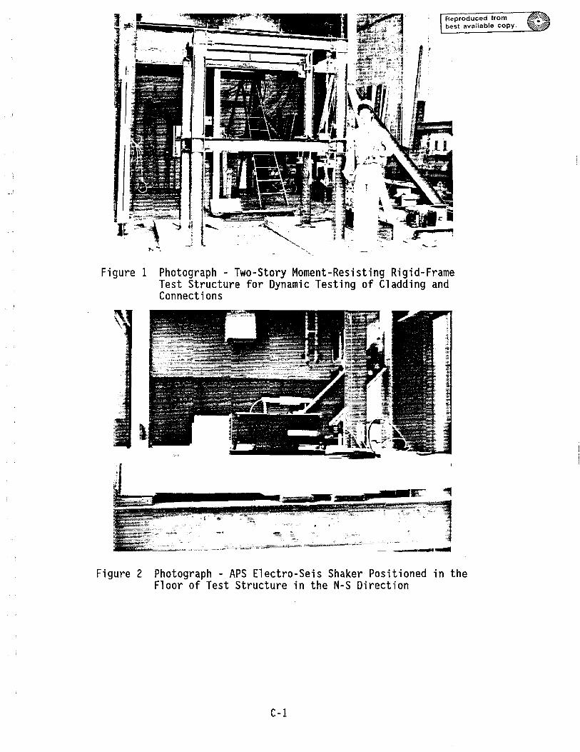
Reproduced from best available copy.
Figure 1 Photograph Two-Story Moment-Resisting Rigid-Frame Test Structure for Dynamic Testing of Cladding and Connections
~ -- --_ ......
Figure 2 Photograph - APS Electro-Seis Shaker Positioned in the Floor of Test Structure in the N-S Direction
C-l
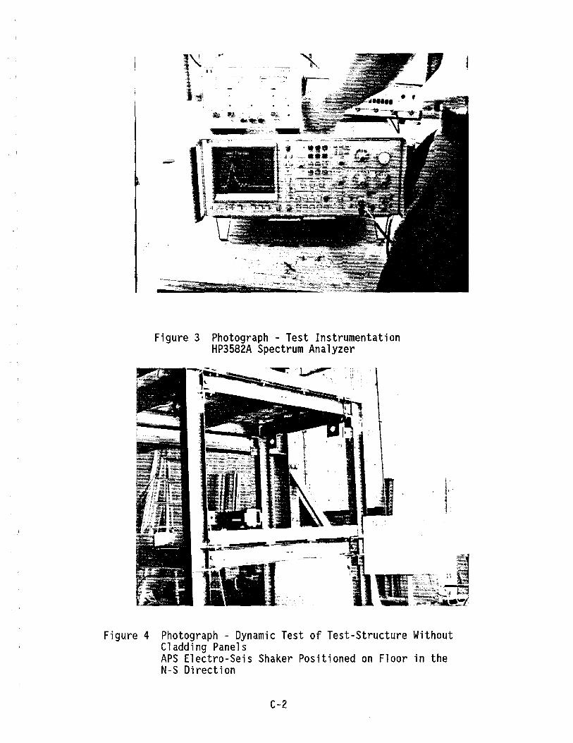
Figure 3 Photograph - Test Instrumentation HP3582A Spectrum Analyzer
j, -,
Figure 4 Photograph - Dynamic Test of Test-Structure Without Cladding Panels APS Electro-Seis Shaker Positioned on Floor in the N-S Direction
C-2
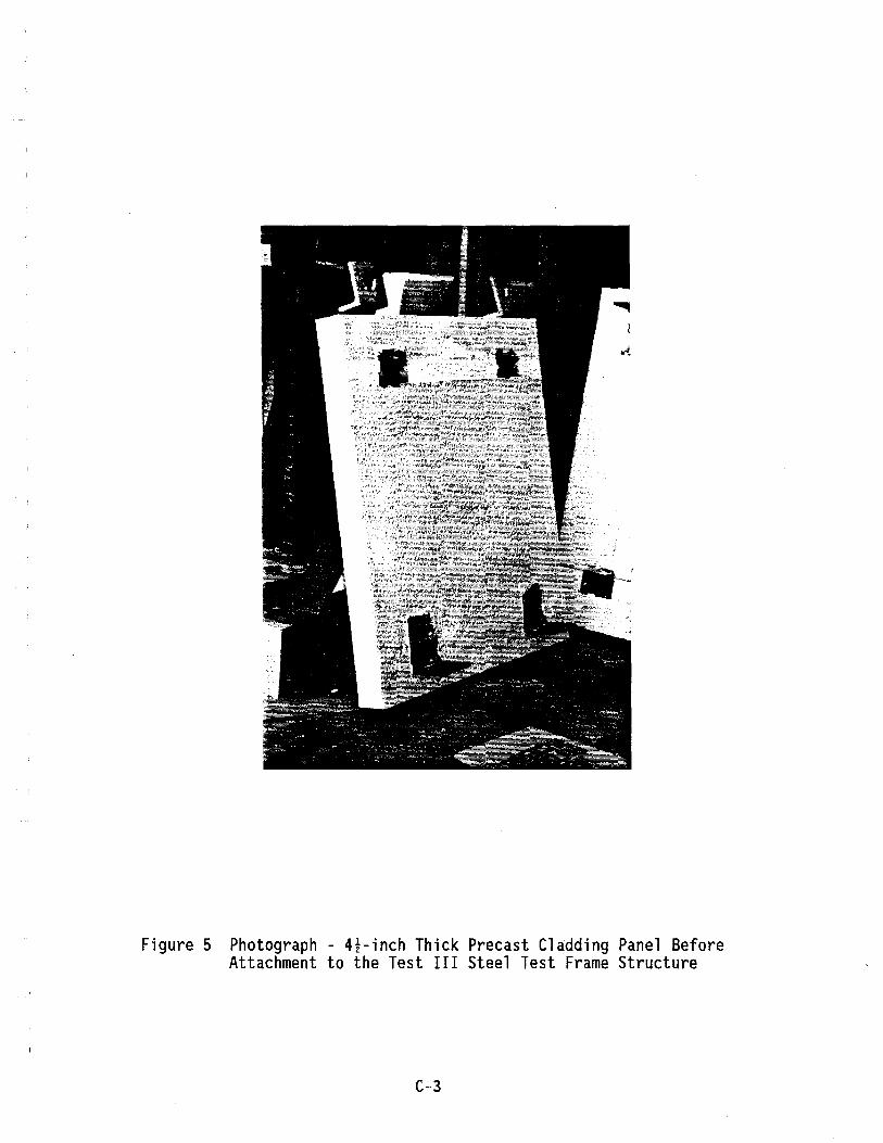
Figure 5 Photograph - 4l-inch Thick Precast Cladding Panel Before Attachment to the Test III Steel Test Frame Structure
C-3

(J
1 .j::>
I)
(9
W C
ox9 At
&
I_d
l -+
. ~I
-dl
~ ~I
-Oil
.
_ .
J ~
'.
Wa,'t~
) -~
$---r
0 ~-
(~'\:' ~
"'-
1 \"
\ ~
::~
rA-ll
I"
Z
..J
~
, .'
.of
'{if
\\f
I.
GI
G
' -.
'"
{
\
-..\
)(
>
( •
>(
Z
~
-S
.~ -3
~ ~
"}
:1
:1
~3
~_
~Hf~\
_H3.
I ~
\ /
Wa,
x3
~ ~
1 N
• 4
-'-\ E:
9®
~ ~Non:.'? t1O~
N-r
-I2
!:6I S
T'f..
jo c.
o~!-Je
c.-onO
fJ ~7
FIR
ST
A
ND
S
EC
ON
D
FL
OO
R
FR
AM
ING
P
LA
N
""CA
I-e V
LI"
,ILo'
l
NS
F
SP
ON
SO
RE
D
RE
SE
AR
CH
P
RO
JEC
T:
~ ~
I I/"/v·
!ljlz.,
,?J><
Yz.1 '
ft,
~ 7/
e/(;
eoc.T
1
wc;
,"'l
/iiJ
c;,
w'}
t
CD B
M~,..~~: !l
~~o~
,NEC
TION
. D
ET
AIL
TE
ST
II
I S
HE
ET
1 S
EIS
MIC
TE
ST
ING
O
F
HE
AV
Y P
RE
CA
ST
F
AC
AD
ES
/ C
LAD
DIN
GS
AN
D
CO
NN
EC
TIO
NS
IN
S
TE
EL
BU
ILD
ING
S
WIT
H
MO
ME
NT
RE
SIS
TIN
G
FR
AM
ES
DY
NA
MIC
T
ES
TIN
G
OF
P
RE
CA
ST
F
AC
AD
E/C
LAD
DIN
G
PA
NE
L A
ND
C
ON
NE
CT
ION
S
ON
A
MO
DE
L T
WO
-ST
OR
Y
ST
EE
L M
OM
EN
T-R
ES
IST
ING
F
RA
ME
S
TR
UC
TU
RE
SE
ISM
IC
TE
ST
F
AC
ILIT
Y
I DRW
N:
AR
CH
ITE
CT
UR
AL
EN
GR
. D
EP
T.
DA
TE
:
CA
L P
OLY
S
TA
TE
U
NIV
ER
SIT
Y
SA
N
LUIS
O
BIS
PO
. C
A 9
3407
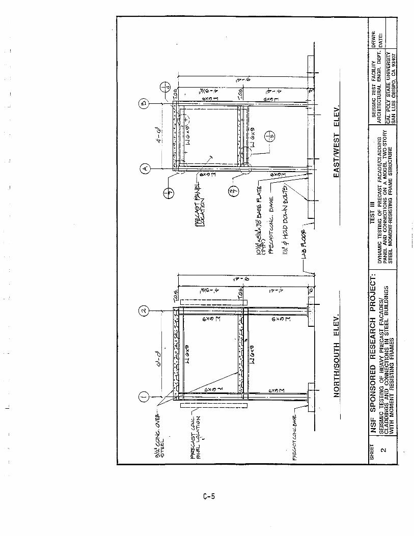
("")
I 01
L 1_
I 2
A
e>
~Y2.·
CO
Ne.
. OVE~~
G>I
-d'
41-c
J1 'b
TE
.E.L
~
'" ~
:4.~"~~:;;!..:~~O.~4 ~.~~ •..
. ".
-r.o
.~.
57l>
'" .-
• .:..
-•• : •• :-
r: ",:~.;,,""'.o' -
~
-r:a€>
.
n W
6>
)(9
n
\ ~
I I
Ww><
.~\_
-t-.
/ -
t"'i'2
UA
5T C
.OIJ
c.. \
1 I
I
1 I
I ~'4EL L
.~G-
A"TI
ON
I I
I I
=
~~j:L~
I I
, \
I I
(i\
(Il
II ~
ct::.
.A1l
0N
t ~
I iI
'~
I I
x x
, I
I f
.s I
x ~
II
~
.s II
~-:J
3
,
II
' :1
::1
.
I I
1"1-
I I
I I
I I
II
II
~ Ii
I
II
-.
I J-r.o
.f>. ~
! J
;!,:;
.::,
~.::;:' ~.·o
.1>
"'
'':'
~',.
' ..
... ;~'
.;..
:: ('~.
I C
o.
c ~.. .~ ..
....
~
II~
't
'\
IU
6'
, W~I(<a
" r;"
-~
~$.~
<yg "
"'" "-
"-rE~
6\
_
'~
~.
~T c.o
!-k::.
. f;>
A0E
. 61
•
x '1
G
\ 'S
03
,
,s
)(
I
IYd
tP H
OW
DO
!,JN
ea
.1?
~
J.
-].
oS
't
-..j
::I
f~ST c:.oNC-'~J
..i..
I/W>
~\
-; \\~
li
I !
I I
T'T
T,,
()r
I .1
I !
. T I
~.
! I
I I
I I
1 I
NO
RT
H/S
OU
TH
E
LE
V.
EA
ST
/WE
ST
E
LE
V.
SH
EE
T
NS
F
SP
ON
SO
RE
D
RE
SE
AR
CH
P
RO
JEC
T:
TE
ST
II
I S
EIS
MIC
TE
ST
FA
CIU
TY
2 S
EIS
MIC
TE
ST
ING
O
F H
EA
VY
P
RE
CA
ST
F
AC
AD
ES
! D
YN
AM
IC T
ES
TIN
G
OF
PR
EC
AS
T
FA
CA
DE
/CLA
DD
ING
A
RC
HIT
EC
TU
RA
L E
NG
R.
DE
PT.
CLA
DD
ING
S A
ND
C
ON
NE
CT
ION
S
IN
ST
EE
L B
UIL
DIN
GS
P
AN
EL
AN
D
CO
NN
EC
TIO
NS
O
N
A
MO
DE
L T
WO
-ST
OR
Y
WIT
H
MO
ME
NT
RE
SIS
TIN
G
FR
AM
ES
S
TE
EL
MO
ME
NT
-RE
SIS
TIN
G
FR
AM
E
ST
RU
CT
UR
E
CA
L P
OLY
S
TATE
U
NIV
ER
SIT
Y
SA
N
LUIS
O
BIS
PO
. C
A 9
3407
DR
WN
:
DA
TE
:
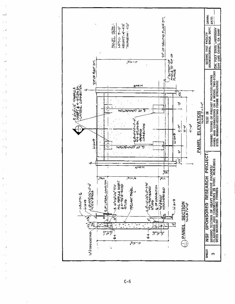
("")
I 0)
1_ ~ C-
Ot..U
MN
£t
L
It d
'x.dx
Yl w
/f~L..f;
IN~-r ~ "
\-~-
ruP~
I=A.
~c.oN~i1ON
<t
1_ , , '.-
Y211~1H~
II~W(P><:<3
4~~
~ W'x'
!>'lz
'xY:l!
lxd-
wll
:~7.i1
I
1'P/
:z!h
H)H
o!..E
.. ~
SH
EE
T
3
~
~ I "+
#-4 "t
l
~
«
f"!+
, -----
-:;
_',
. ~4
:.01
"L."
'~~l
!C;r
~loI
~ 7
'-"-
,lJI
,. \'~/t. (
p'IX
(pllx
'l:.1
I iJj
y,i'
• 0 ~FAl. ~ IN~
F-r
~. ~
~4-'7/e~¢H~
",
~"U~
~ b
I ~
~,.
. I p~r~~
J ..
..
i.
' ,
'" " ~ ~ 3
.==ri~~~
. I-
-_
... ~
..
:d
2. z
. ~
'-d
x(JI
)(V
il,(O
I_4
>"
~
-~N(!:I
~
'To
rtf'
~a?f'
e>H.
~ 3.
f7ANe
L Si
Ze.:
LJI
Pn
-i:
'71 -
<;>,1
HE:! e
.1-f
'T~ -
41-4
';.i1
~« I
1"
H1'*
'Ne~
" 41
' zll
'" ~ , 'l
-~ ll
olf"l-
~1i.Jt
?~ eA
. \
\L
I -C
/. CONN~
11ON Bl
~~--l~
t-111 "
uJl x
Yt!x
0'-
o;;?>
/+I
,_
,
~~e'HMP~p
-r -:
-1
.:1
tZ:
'~-~~ _
>--83
-_ -~~~
--~F .
WI'
Of ~""'N
P fiA>"1>
C1.
iJ/F
OU
ND
l:l?e
NP
t-~
R=
4.
'==~
---~
---
'~if
. ,
l"f'0
11'O
M o
f ~-.
, A
NaL
!!: ,0 "
for
of
~ ',
,,II
'
'--W
(Pl(
9
w (P)
(~
fLA
Nce
~'_"711
~I
4}:z,
"
CD PA
NE
L
SEC
TIO
N
-?G
.Al.
.~ I
lleI'-
ell
14\!z
."1
9"
-~~-~~~------=:::....-=--
~-91
1
1 -.1'_<p~ __
PAN
EL
ELEV
ATI
ON
NSF
SP
ON
SOR
ED
R
ESEA
RC
H
PRO
JEC
T:
SE
ISM
IC T
ES
TIN
G
OF
H
EAV
Y P
RE
CA
ST
F
AC
AD
ES
/ C
u\D
DIN
GS
AN
D
CO
NN
EC
TIO
NS
IN
S
TE
EL
BU
ILD
ING
S
WIT
H
MO
ME
NT
RE
SIS
TIN
G
FR
AM
ES
'?O
tL-e
I"
::: 1
'-0'1
TES
T II
I S
EIS
MIC
TE
ST
FA
CIU
TY
D
RW
N:
. A
RC
HIT
EC
TU
RA
L E
NG
R.
DE
PT.
D
YN
AM
IC
TE
ST
ING
O
F P
RE
CA
ST
FA
CA
DE
/CLA
DD
ING
D
AT
E:
PA
NE
L A
ND
C
ON
NE
CT
ION
S
ON
A
M
OD
EL
TW
O-S
TO
RY
C
AL
PO
LY
STA
TE
UN
IVE
RS
ITY
S
TE
EL
MO
ME
NT
-RE
SIS
TIN
G
FR
AM
E
ST
RU
CT
UR
E
SA
N
LUIS
O
BIS
PO
. C
A 9
3407

n I "'-J
P~C/GT
PANE
-I...
0P~IMIHI
W~J'.~-- ~.l
Ir-}
'r-_
_ ...:
l~
( !,
'
1_
Yi'
1111
LA<-
tt-
P~T
PANe
L .;p
e:c I
M EtI
W(p
x9
• ~~r-T-
'710' ~
fIt..
I.tW
.,-n.
J11
SH
EE
T
4
4f4
~
Y.:<. u f
T#p
&We;
o fo
P
;J-IUT
~ W
ITt!
~II .
• 11
'<
&\IE
fZF.
l(Z&
W~ E:
P-I?
-2~ 'P
Hol.c
IN
,4N9
t..&-
~<O~
¥Y:z
.-~I
I\..
O\.J
O
ED DU
.CT
ILE
CO
NN
EC
TIO
N-S
EC
TIO
N
~L~ \ -
;3'!.
i!.t>
tI
y:z.
.Ii.fT
HH
:;J,o
ep F
w'
NUT,
? WI
TIt~
" (;v
ep..-e
.IZ6-w~
2 ~ 11
4' fiO
i.,e
ft-l AN~
~
ED DU
CT
I"E
CO
NN
EC
TIO
N-B
OT
T::
: ~~~~
NS
F S
PO
NS
OR
ED
RE
SE
AR
CH
PR
OJ
EC
T:
TES
T III
S
EIS
MIC
TE
ST
FA
CIL
ITY
D
RW
N:
GIL
SE
ISM
IC T
ES
TIN
G O
F H
EA
VY
PR
EC
AS
T F
AC
AD
ES
I C
LAD
DIN
G A
ND
C
ON
NE
CT
ION
S I
N S
TE
EL
BU
ILD
ING
S
WIT
H :
MO
ME
NT
RE
SIS
TIN
G F
RA
ME
S
DY
NA
MIC
TE
ST
ING
O
F P
RE
CA
ST
FA
CA
DE
/CLA
DD
ING
A
RC
HIT
EC
TU
RA
L E
NG
R.
DE
PT
. D
AT
E:
%7
P
AN
EL
AN
D C
ON
NE
CT
ION
S
ON
A
MO
DE
L T
WO
·ST
OR
S
TE
EL
MO
ME
NT
.RE
SIS
TIN
G
FR
AM
E
ST
RU
CT
UR
E
CA
L P
OL
Y S
TA
TE
UN
IVE
RS
ITY
C
HC
K:
SA
N
LUIS
O
BIS
PO
, C
A
93
40
7
DA
TE
:
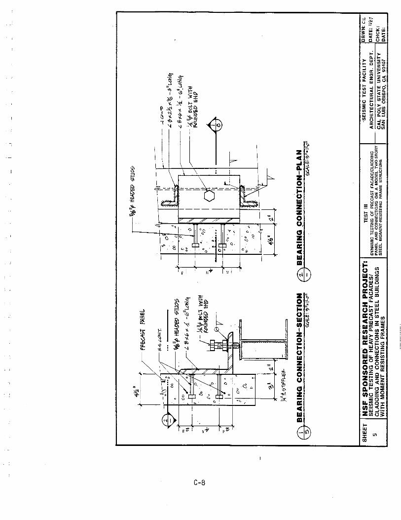
n I co
~
'" *" ~
T~"
P~T
PAH&
l.
#-4.
?ON
T.
/I--
~1If
> ~DE!?
';;'1Uo~
01 0
0
0,
~,
I ~II
t. 'b
'l-"
>'!i
-i01l
Lctl9
Ji4"
rtq,
'lfF
I-Jt
:It-
~~~e
-~e.
!:1 =
=
n. ()
{)
C o. 0
0
~
L._
I ~ "f
tt~!7EP ~u~
0 r~-
~ ~~
W CPK~
____
-,4
~"2~"% _?'
It..
cN~
J-
1".
! ~ I
~ e.l'¥
>>' !
i. -0
'~LP
N4
C
[;
/' ~I
l? l
7o\.T
w
mt
'I II ~:F-
-rT\
r~
PI~
rz.PU
N!7E
:1:1
&H Ii
A
"\V
(1) B
EA
RIN
G C
ON
NE
CT
ION
-SE
CT
ION
5
€CAt
.e: ~
II,,'LO"
®B
EA
RIN
G ~ONNECTION-PLAN
~t.I::~II .
. jl·O
"
SH
EE
T
5
NS
F S
PO
NS
OR
ED
RE
SE
AR
CH
PR
OJ
EC
T:
SE
ISM
IC T
ES
TIN
G O
F H
EA
VY
PR
EC
AS
T F
AC
AD
ES
! C
LA
DD
ING
AN
D
CO
NN
EC
TIO
NS
IN
ST
EE
L B
UIL
DIN
GS
W
ITH
MO
ME
NT
RE
SIS
TIN
G F
RA
ME
S
TE
ST
II
I 'S
EIS
MIC
TE
ST
FA
CIL
ITY
D
RW
N:
elL
DY
NA
MIC
TE
ST
ING
O
F
PR
EC
AS
T
FA
CA
DE
/CLA
DD
ING
A
RC
HIT
EC
TU
RA
L E
NG
R.
DE
PT
. D
AT
E:
IVfl
7
PA
NE
L A
ND
CO
NN
EC
TIO
NS
O
N A
M
OD
EL
lW
O·S
TO
RY
/--~~"":':''':''='':'':'''::'':'~:'''::~:::=-='::'':''':'':'.......j
ST
EE
L M
OM
EN
T·R
ES
IST
ING
F
RA
ME
S
TR
UC
TU
RE
C
AL
PO
LY
ST
AT
E U
NIV
ER
SIT
Y
CH
CK
: S
AN
LU
IS
OB
ISP
O,
CA
93
407
DA
TE
:
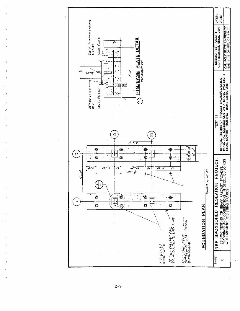
n 1 ~
IOli'I
X8~'
t.II
X~
2:>~.~
f·-'
:".t
:.
5" -:
-<I~ ~
F-U"'?"" U1-JC.;--~/ I
©l
~"'?
"" ev_~ -r
o L.
A.~
f[..a>
:Z-
";'-0
"-; ?
;JI-a
" ' ...
;,,'(
ou
l -
-----
?fTl~P;-'
of' 1
'12"
tJ11
hr~o
eD
pi4
aF
-1~"'~""0
FOU
ND
ATI
ON
PL
AN
(p'-
o~ ~ -'
+ I~+-I:~-~.
~II,
,'I
' -~
t:
._
---+-1~
a, .-<~-+.
... ~I~
1 C)
=
]
;I-~
•
_I t
:LI-d
'
~AL.e Y:z"~II-O'1
SH
EE
T
NSF
SP
ON
SOR
ED
R
ESE
AR
CH
PR
OJE
CT
: T
ES
T
III
1~'I
41 H
ell_"
t<:l
Nr-J
IXlL
-T
--
'JltJ
" f
f'M ...
e.o.
Jl7 C
AP;;<
.>l.-t:
: ",t
-Jc.
Hof
.t;,
'-'"So
f'u
t>T
6
r-----o~
.=9' :~.
A~~"="
-'~ ]
"l ~
t'-o
'l 1
1
ED F
TG./
~~~~
ii~~
~TE
DETA
IL
6 S
EIS
MIC
TE
ST
ING
O
F H
EA
VY
P
RE
CA
ST
F
AC
AD
ES
/ C
LAD
DIN
GS
A
ND
C
ON
NE
CT
ION
S
IN
ST
EE
L B
UIL
DIN
GS
W
ITH
M
OM
EN
T R
ES
IST
ING
F
RA
ME
S
DY
NA
MIC
TE
ST
ING
O
F P
RE
CA
ST
FA
CA
DE
/CLA
DD
ING
P
AN
EL
AN
D
CO
NN
EC
TIO
NS
O
N
A
MO
DE
L lW
O-S
TO
RY
S
TE
EL
MO
ME
NT
-RE
SIS
TIN
G
FR
AM
E
ST
RU
CT
UR
E
SE
ISM
IC
TES
T F
AC
ILIT
Y
I DR
WN
: A
RC
HIT
EC
TU
RA
L E
NG
R.
DE
PT
. D
AT
E:
CA
L P
OLY
S
TATE
U
NIV
ER
SIT
Y
SA
N
LUIS
O
BIS
PO
. C
A
9340
7

(J
I I-
-'
a
~
~~
~'"
Ii::
~
b~
'-'
-
-0
---It
--
II II --
-H--
-II II
r-.-
, ..... _'
LI
L --
rr
," '"
'I"."
'i:' -
'1'-
' i
I-_
_ -J
I r-
-rr
I -!
L_
.!.._
-S
Vllt-
1' ~
;I",
x V
i It
5 Y2
.)( I
lo/Ic.~
Yz" I
t
5 V2
. x I
'!oIl"
~ )'
1" I
t. lO
P! ~TiOH
,-"Ve
"e!>
~L.T5
(NF
'Ic;..
-.L.
) 1 V
e.", 2
1'e.
"
1 Yel'
1 -re
i
3Vt.
~.1"
1 Ft.
Z-o/
e.' 4>
r:>
Ol.f
o
l.h+"
Y2l
'-!>Y
:z.iI
--------
- "
OV
z.)(
llo/l(
P'V
z."ft
.
E:r
.os.
+,+~ V
i' It-
~
"--f.
P
z.-'o/e."~ ~1.1
?IV:!.
I(';
X V:
I." fl
-y~" cP
r:>O
L:T
Z -'¥
e>" ~
~L.
rf)
L-+'+'Y:l."x~Y;
t..Of-l6
! --
.. --
e.Yotx
4-6 /1
.. )(
yz" I
t o
I~"'.
2 Ye
.""~
" 7~ -
, . .J..
...-'-
"/
---
~
J L
Li
., , ~
'l"\:
---
_-r IJ
ZY
1" ~
\ ,,-
'Jj~'P
ff'fii
l -.
_-
-5Y
u4
~/1i"V:l.
r Y4"
,H
ill RIG
ID
FR
AM
E
CO
NN
EC
TIO
N
DE
TA
IL
® R
IGID
F
RA
ME
C
ON
NE
CT
ION
D
ET
AIL
®
RIG
ID
FR
AM
E
CO
NN
EC
TIO
N
DE
TA
IL
f5\
w
--1t--
--,---
II __
_ ll_
l / ~ F'
P.
II -
1\'
II II II r-
I-
±=
--iF
-,
t-=jF
==
I -+
-L_~
}_
4i1_
f
2.-~/
e"9 W~T5
"I-
~f!-
I
I -
--
-0
-OJ
~~
I .. - ~ .~
I
z --1>
/e."4>
BG
il.f5J
l. 4
.4 •
h"-~
,Y1'
l-O
IJGl
'~ '-
'Is
I / / I
/ /
1/
fl
---
/~<I"f'.
F~ /
1
NQTE-~
I) J
-LL
CO
L-U
Mf.l
S
AI'-
C
j..J
u,.
9
2.)~
L-L ee~M5
A~e
WiP
""
!»~1.L-
J..l
e~D6
"'~e
0/1""
FIL
U'f
w
eL
DS
o
f.le
51
0e
of
.ll.-Y
U
NL-
eS5
oie
RW
l5E
. ~OI~P
!!>!z
, 1 'o/
liP "
Yz"
fI.
5 !/z
. xl
'0/1
0' :
12"
It
/f--<
f. p.
~-
0/2
..+
£;-1
,,,,, V
L" I
t-
ED
RIG
ID
FR
AM
E
CO
NN
EC
TIO
N
DE
TA
IL
® RIG
ID
FR
AM
E
CO
NN
EC
TIO
N
DE
TA
IL
® RI
GID
F
RA
ME
C
ON
NE
CT
ION
D
ET
AIL
SH
EE
T
7 N
SF
SPO
NSO
RED
R
ESEA
RC
H
PRO
JEC
T:
SE
ISM
IC
TES
TIN
G
OF
HE
AV
Y P
RE
CA
ST
FA
CA
DE
S!
CLA
D D
ING
S
AN
D
CO
NN
EC
TIO
NS
IN
S
TEE
L B
UIL
DIN
GS
W
ITH
M
OM
EN
T R
ES
ISTI
NG
FR
AM
ES
TE
ST
II
I D
YN
AM
IC T
ES
TIN
G
OF
PR
EC
AS
T
FA
CA
DE
/CLA
DD
ING
P
AN
El:.
AN
D C
ON
NE
CT
ION
S
ON
A
MO
DE
L T
WO
-ST
OR
Y
ST
EE
L M
OM
EN
T-R
ES
IST
ING
F
RA
ME
S
TR
UC
TU
RE
SE
ISM
IC
TE
ST
F
AC
IUT
Y
AR
CH
ITE
CT
UR
AL
EN
GR
. D
EP
T.
CA
L P
OLY
S
TA
TE
U
NIV
ER
SIT
Y
SA
N
LUIS
O
BIS
PO
. C
A 9
3407
Ft.
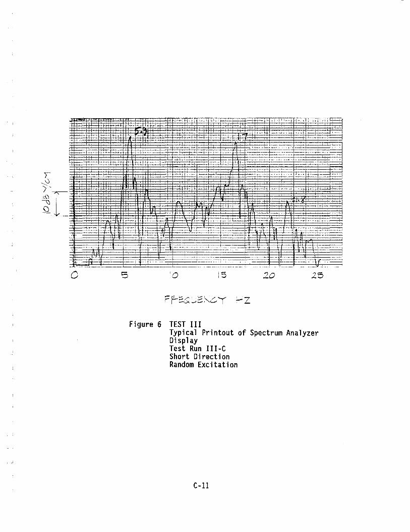
, or: '~
. t
, -r-
Figure 6 TEST III
, '~>',
15
. , ,.
2{)
't-
" .. , .. ,.,., .. 25
Typical Printout of Spectrum Analyzer Display Test Run III-C Short Direction Random Excitation
C-ll
I I I