seismic assessment of horizontal cylindrical … assessment of horizontal cylindrical reservoirs...
TRANSCRIPT
International Conference on Seismic Design of Industrial Facilities
© 2013, RWTH Aachen University
Seismic assessment of horizontal cylindrical reservoirs
Christos Baltas1, Pierino Lestuzzi1, 2, Martin G. Koller1 1 Résonance Ingénieurs-Conseils SA
21 rue Jacques Grosselin, 1227 Carouge, Suisse [email protected], [email protected]
2 Ecole Polytechnique Fédérale de Lausanne EPFL Station 18, 1015 Lausanne, Suisse [email protected]
ABSTRACT :
Industrial facilities contain a large number of constructions and structural components. Both building and non‐building structures typically can be found in an industrial/chemical plant. Above ground pressurised tanks are typical examples of non‐building structures of such sites. These equipment are typically used for the storage of gas and liquid materials, e.g. chlorium, ammonia etc. The overall design of such structures, especially in low to moderate seismicity areas, has neglected any seismic loading in the past, basically due to the absence of relevant seismic requirements in previous codes. The seismic security of above ground pressurised tanks is of great importance, since failure of these structures can lead to negative impact for the environment and to economic losses. Recent codes for seismic design and construction of horizontal cylindrical reservoirs provide tools which can serve also to assess existing tanks. From experience, the seismic deficiencies of reservoirs of this type are in general concentrated in some strategic points. This paper describes the main deficiencies of such structures and the simplified methodology used for their assessment based on the guidelines presented in Eurocode 8. In addition, typical cost effective solutions for the retrofit of the tanks with these shortcomings are presented and critically discussed. The above assessment and retrofit methodology is illustrated for some examples of typical equipment.
Keywords: horizontal cylindrical reservoirs, seismic assessment, structural seismic deficiencies, retrofit
1 Introduction
Above ground pressurised tanks are typical examples of non‐building structures of industrial facilities sites [1]. These equipment are typically used for the storage of
International Conference on Seismic Design of Industrial Facilities
© 2013, RWTH Aachen University
gas and liquid materials, e.g. chlorium, ammonia etc. The overall design of such structures, especially in low to moderate seismicity areas, has neglected any seismic loading in the past, basically due to the absence of relevant seismic requirements in previous codes. The seismic security of above ground pressurised tanks is of great importance, since failure of these structures can lead to negative impact for the environment and to economic losses. Recent codes for seismic design and construction of horizontal cylindrical reservoirs provide tools which can serve also to assess existing tanks. From experience, the seismic deficiencies of reservoirs of this type are in general concentrated in some strategic points. This paper describes the main deficiencies of such structures and the simplified methodology used for their assessment based on the guidelines presented in Eurocode 8. In addition, typical cost effective solutions for the retrofit of the tanks with these shortcomings are presented and critically discussed. The above assessment and retrofit methodology is illustrated for some examples of typical equipment.
2 Type of reservoir
2.1 Dimensions, Materials
Typically, the horizontal reservoirs have a cylindrical shape with flat or spherical ends. Their volume varies from small 1 t to larger 500-800 t [Web-1]. Their main body-structure is manufactured from structural steel. Due to internally applied pressure and the static system itself, the steel thickness of these reservoirs is usually quite important. Indicatively, this can exceed a thickness of 2 cm.
Tanks of this type, in general, are supported, at the level of the ground, on reinforced concrete foundation systems.
The configuration of their supporting system, meaning the system which transfers the forces from the structure of the tank to the foundation system, depends on their weight, dimensions, the elevation height and the seismicity. For tanks constructed few meters above the ground the supporting system may include only simple elements. Indicatively, these include steel plates, bearings and bolts.
2.2 Bearings, fixed and sliding
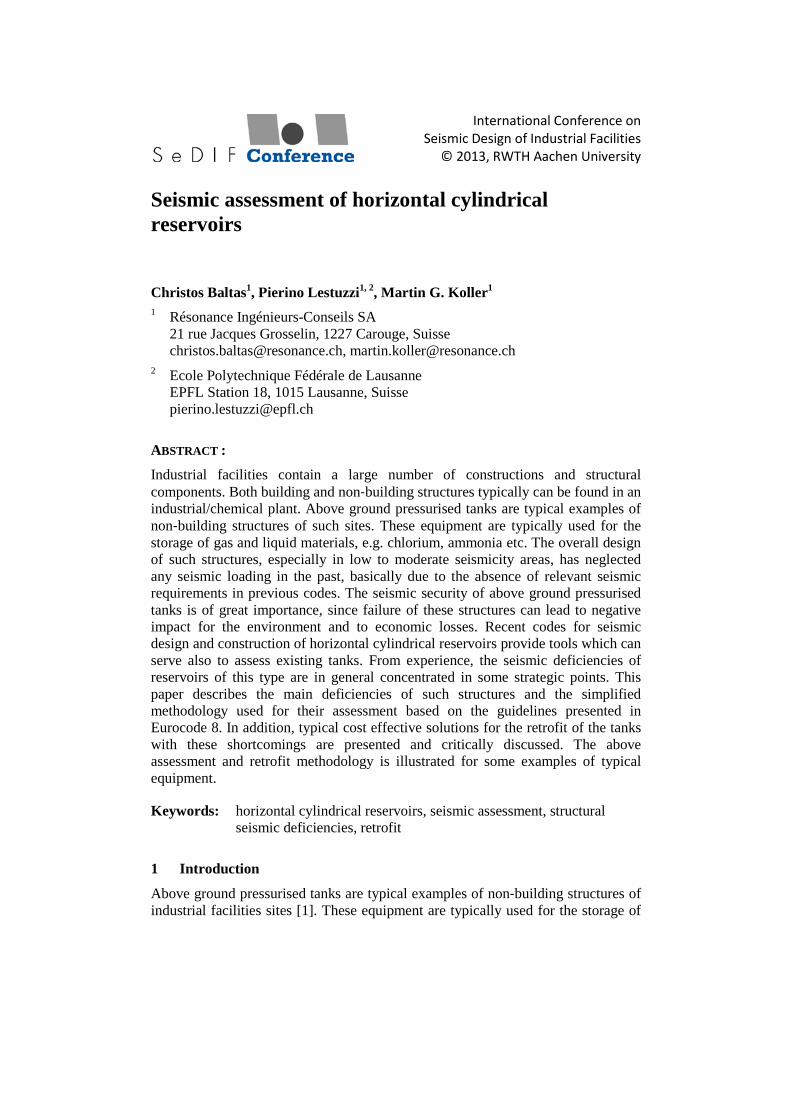
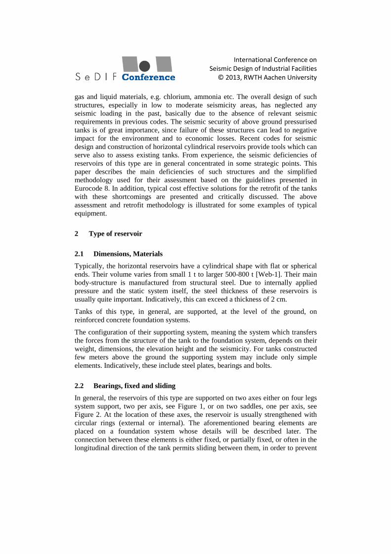
In general, the reservoirs of this type are supported on two axes either on four legs system support, two per axis, see Figure 1, or on two saddles, one per axis, see Figure 2. At the location of these axes, the reservoir is usually strengthened with circular rings (external or internal). The aforementioned bearing elements are placed on a foundation system whose details will be described later. The connection between these elements is either fixed, or partially fixed, or often in the longitudinal direction of the tank permits sliding between them, in order to prevent
International Conference on Seismic Design of Industrial Facilities
© 2013, RWTH Aachen University
additional loading of the foundation system, but also of the entire structure, from temperature changes, differential settlements and other loads with similar effects. The longitudinal direction is along the elongated dimension of the reservoir. Hence, it is not rare that the bearing elements of one of the two axes are fixed on the foundation and the opposite elements are free to slide, a configuration unfavourable for a good seismic behaviour of the structure, since the seismic loading is concentrated on few elements. The sliding connection is usually achieved with guided in one direction sliding bearings. Sometimes, this special detail is omitted. Instead, the bearing element rests on the foundation system without providing any special detailing. Hence, the only mean of transferring a horizontal force is via friction which depends mainly on the roughness of the interface and the axial load which sometimes can be reduced to zero. This kind of supports does not provide a satisfactory seismic behaviour. In fact, large torsion effects can be developed for such kind of supports. Concerning fixed connections, these are constructed by fixing the bearing element on the foundation with bolts. These are able to transfer some horizontal loads mainly due to wind, but usually unable to transfer the total seismic forces.
Figure 1: Horizontal cylindrical reservoirs resting on four legs system
support.
Figure 2: Horizontal cylindrical reservoirs resting on saddles of support.
International Conference on Seismic Design of Industrial Facilities
© 2013, RWTH Aachen University
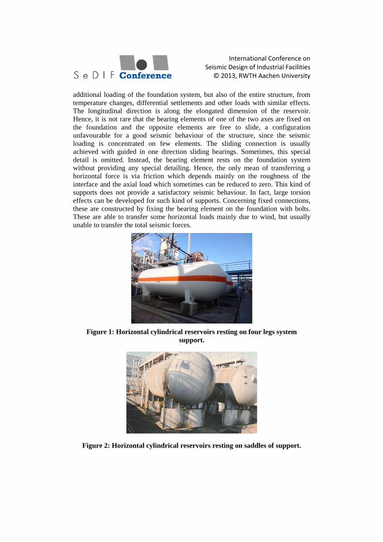
Figure 3: Horizontal cylindrical reservoirs resting on saddles.
Experience has shown that the number of the bolts as per the construction drawings is in reality smaller, as shown in Figure 3. For that reason, a very good check of the actual condition of the structural elements of the tanks is essential before any assessment procedure.
2.3 Foundations, isolated and lab on grade
The foundation system usually comprises some of the following elements: independent footings, connecting beams, slab on grade and piles. The foundation system, designed for transmitting merely static, vertical loads to the ground has relatively small dimensions in terms of area. The dimensions of the foundation are also usually limited by the dimensions of the reservoir in plan view. One reason for this configuration is that often more than one reservoir is constructed in a row, each close to each other due to space limitations. The space, below or close to the tank, required for the attachment of pipes on it is an additional reason of the limited dimensions and the configuration of the foundation elements.
On one hand, when four legs system support is provided for the tank, then the foundation system usually comprises four column-shape elements founded on four independent footings. On the other hand, when two saddles of support are used, then the foundation system comprises two wall shape elements founded on a longer footing, perpendicular to the longitudinal axis of the tank. Sometimes the latter system is used also for the four legs system support case. Now the above elements are connected via a slab on grade or they are completely independent.
Being small in plan view, the foundations are susceptible to overturning when subjected to earthquake loading, and the column-shape and more rarely the wall-element shape structural elements described above are susceptible to flexure and shear failure.
International Conference on Seismic Design of Industrial Facilities
© 2013, RWTH Aachen University
3 Seismic loading
3.1 Seismic action
The horizontal seismic action to be used for the design of tanks should be that defined in EN 1998-1 [2]. For the case of the assessment of existing tanks, the same seismic actions may be used. EN 1998-1 provides information concerning the vertical component of the seismic action that could be used.
The importance factor γI taken into consideration depends on the importance class of each structure. This class depends on the potential loss of life due to the failure of the particular structure and on the economic and social consequences of failure. For example, a Class IV, as per EC8, refers to situations with high risk to life and big economic and social consequences of failure. Further description of each class can be found on EN 1998 and EN 1990 [3]. Eventually, in case of exceptional risk to life and extreme economic and social consequences of failure, the importance factor may be increased. It is important that the importance class of each structure is well defined in order to set the requirements for the assessment procedure as well as for eventual retrofitting of a tank. In general, the importance factor is imposed for each country from National authorities.
The contribution of each component will be derived for the value of q and of the damping ratio considered appropriate for the corresponding component [4].
3.2 Structural response
For steel tanks, the inertia forces on the shell due to its own mass are small compared with the hydrodynamic forces, as described in the following paragraph.
3.3 Content response
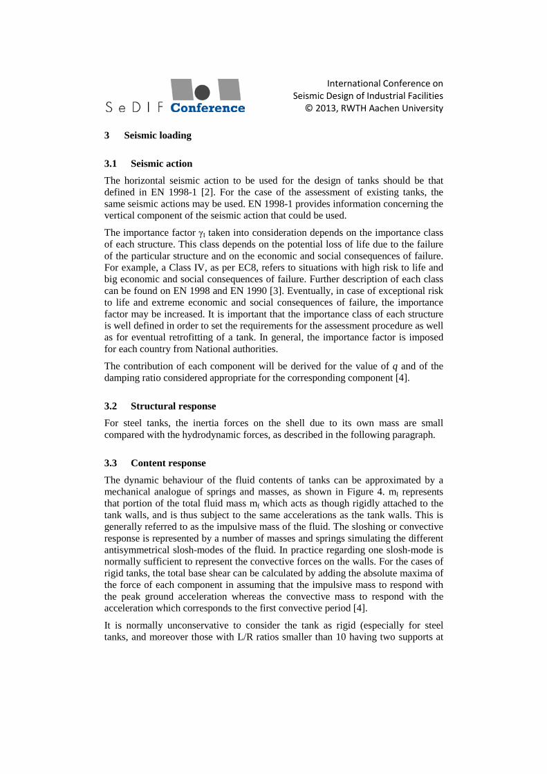
The dynamic behaviour of the fluid contents of tanks can be approximated by a mechanical analogue of springs and masses, as shown in Figure 4. mI represents that portion of the total fluid mass mf which acts as though rigidly attached to the tank walls, and is thus subject to the same accelerations as the tank walls. This is generally referred to as the impulsive mass of the fluid. The sloshing or convective response is represented by a number of masses and springs simulating the different antisymmetrical slosh-modes of the fluid. In practice regarding one slosh-mode is normally sufficient to represent the convective forces on the walls. For the cases of rigid tanks, the total base shear can be calculated by adding the absolute maxima of the force of each component in assuming that the impulsive mass to respond with the peak ground acceleration whereas the convective mass to respond with the acceleration which corresponds to the first convective period [4].
It is normally unconservative to consider the tank as rigid (especially for steel tanks, and moreover those with L/R ratios smaller than 10 having two supports at
International Conference on Seismic Design of Industrial Facilities
© 2013, RWTH Aachen University
their ends [5]). In flexible tanks, the fluid pressure is usually expressed as the sum of three contributions, referred to as: ‘rigid impulsive’, ‘sloshing’ and ‘flexible’ [4]. Nevertheless, simplified ways for defining an acceptable value of the total base shear have been proposed by several researchers [4]. One of these concludes that this can be done by adding the seismic force of the impulsive and sloshing component in assuming the entire impulsive mass to respond with the amplified absolute response of the flexible tank system.
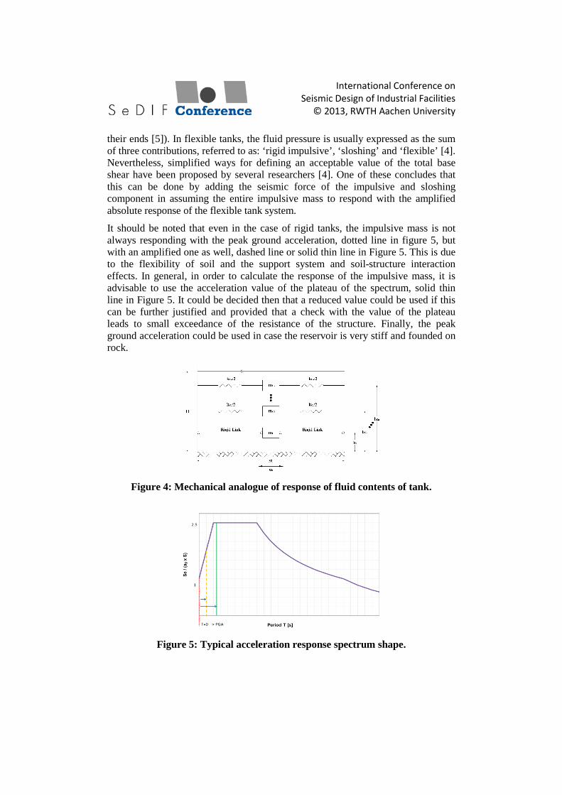
It should be noted that even in the case of rigid tanks, the impulsive mass is not always responding with the peak ground acceleration, dotted line in figure 5, but with an amplified one as well, dashed line or solid thin line in Figure 5. This is due to the flexibility of soil and the support system and soil-structure interaction effects. In general, in order to calculate the response of the impulsive mass, it is advisable to use the acceleration value of the plateau of the spectrum, solid thin line in Figure 5. It could be decided then that a reduced value could be used if this can be further justified and provided that a check with the value of the plateau leads to small exceedance of the resistance of the structure. Finally, the peak ground acceleration could be used in case the reservoir is very stiff and founded on rock.
Figure 4: Mechanical analogue of response of fluid contents of tank.
Figure 5: Typical acceleration response spectrum shape.
International Conference on Seismic Design of Industrial Facilities
© 2013, RWTH Aachen University
3.4 Forces to be considered
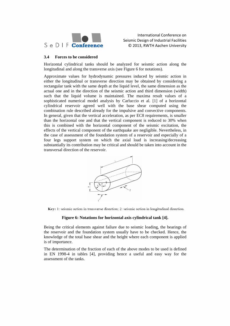
Horizontal cylindrical tanks should be analyzed for seismic action along the longitudinal and along the transverse axis (see Figure 6 for notations).
Approximate values for hydrodynamic pressures induced by seismic action in either the longitudinal or transverse direction may be obtained by considering a rectangular tank with the same depth at the liquid level, the same dimension as the actual one and in the direction of the seismic action and third dimension (width) such that the liquid volume is maintained. The maxima result values of a sophisticated numerical model analysis by Carluccio et al. [1] of a horizontal cylindrical reservoir agreed well with the base shear computed using the combination rule described already for the impulsive and convective components. In general, given that the vertical acceleration, as per EC8 requirements, is smaller than the horizontal one and that the vertical component is reduced to 30% when this is combined with the horizontal component of the seismic excitation, the effects of the vertical component of the earthquake are negligible. Nevertheless, in the case of assessment of the foundation system of a reservoir and especially of a four legs support system on which the axial load is increasing/decreasing substantially its contribution may be critical and should be taken into account in the transversal direction of the reservoir.
Figure 6: Notations for horizontal axis cylindrical tank [4].
Being the critical elements against failure due to seismic loading, the bearings of the reservoir and the foundation system usually have to be checked. Hence, the knowledge of the total base shear and the height where each component is applied is of importance.
The determination of the fraction of each of the above modes to be used is defined in EN 1998-4 in tables [4], providing hence a useful and easy way for the assessment of the tanks.
International Conference on Seismic Design of Industrial Facilities
© 2013, RWTH Aachen University
4 Simplified analysis
4.1 Verification of bearings
In order to determine the seismic demand of the bearings, simple models can be used. Being quite stiff and strong, the reservoir from experience can transmit the horizontal seismic force to its bearings. The latter, designed merely to withstand loads from the weight of the reservoir and its content as well as small horizontal loads imposed from wind loading of the reservoir, have usually insufficient capacity to withstand seismic loads, even when situated in small to moderate seismicity regions. Careful check should be performed for all its constituent components: steel plates, bolts, welds and other bearing equipment.
4.2 Verification of foundations
An additional critical control for the assessment integrity of the reservoirs is the one of the foundations. In order to assess if the foundation can transmit the seismic loads at the ground their structural capacity should be first checked. Secondly but still important, a control of overturning stability and sliding of the foundation system should be effectuated. For instance, for the case of a rectangular footing, the eccentricity of loading should be checked not to exceed the 1/3 of its width as per EC7 [6]. The soil stresses below the foundation should be checked as well. These, in general, should not exceed the bearing resistance of the foundation soil. Nevertheless, in some cases, the exceedance of the aforementioned value of the 1/3 as well as the bearing capacity of the foundation soil could be tolerated [7].
5 Typical example
5.1 Numerical example
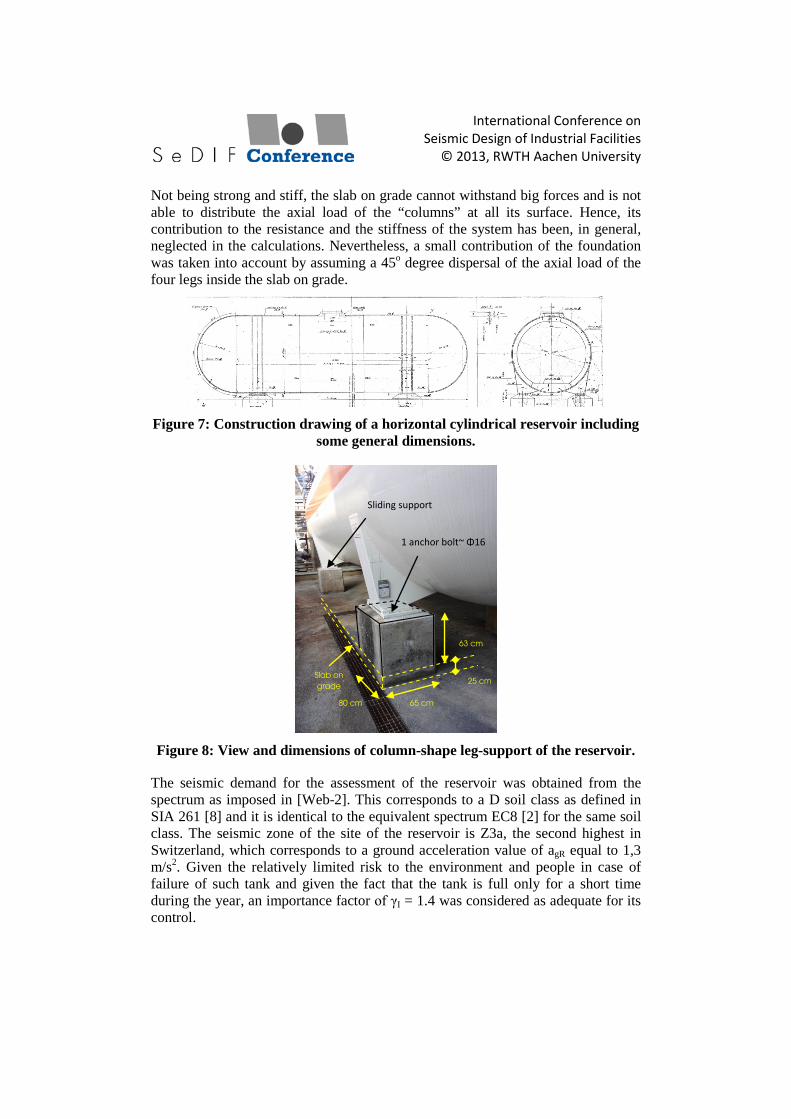
A horizontal cylindrical steel reservoir situated in Monthey, Switzerland, is assessed using the aforementioned simplified method hereafter. A general view of the reservoir with some general dimensions is shown in Figure 7.
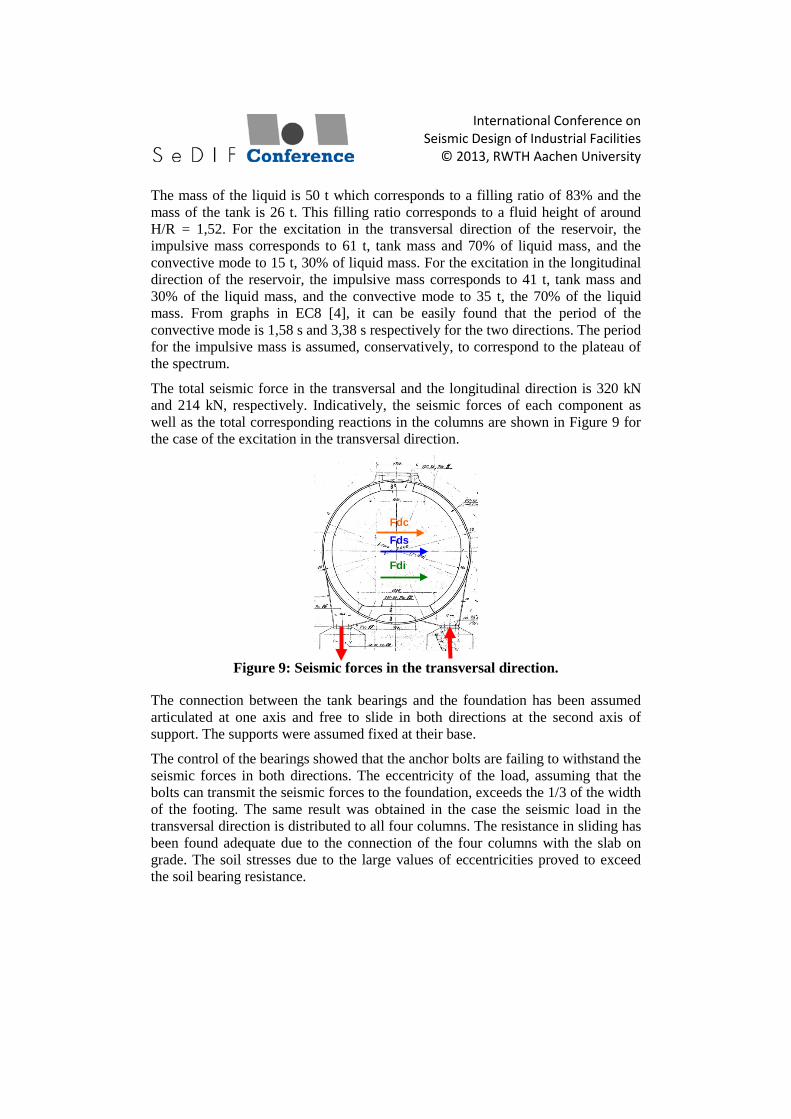
A closer view of the foundation system with its dimensions is shown in Figure 8. In the same figure, the support conditions of the reservoir on the two legs of support are shown, one of each support axis. The absence of anchoring of the bearings on the second axis support yields to a sliding support of the reservoir in both horizontal directions.
The diameter of the reservoir is 1.3 m. Its length is 9,0 m approximately. The distance between the supports in the longitudinal and the transversal direction is 5,0 m and 1,9 m respectively. A four legs system support has been adopted for this reservoir. A slab on grade of approximately 25 cm thickness connects them.
International Conference on Seismic Design of Industrial Facilities
© 2013, RWTH Aachen University
Not being strong and stiff, the slab on grade cannot withstand big forces and is not able to distribute the axial load of the “columns” at all its surface. Hence, its contribution to the resistance and the stiffness of the system has been, in general, neglected in the calculations. Nevertheless, a small contribution of the foundation was taken into account by assuming a 45o degree dispersal of the axial load of the four legs inside the slab on grade.
Figure 7: Construction drawing of a horizontal cylindrical reservoir including
some general dimensions.
Figure 8: View and dimensions of column-shape leg-support of the reservoir.
The seismic demand for the assessment of the reservoir was obtained from the spectrum as imposed in [Web-2]. This corresponds to a D soil class as defined in SIA 261 [8] and it is identical to the equivalent spectrum EC8 [2] for the same soil class. The seismic zone of the site of the reservoir is Z3a, the second highest in Switzerland, which corresponds to a ground acceleration value of agR equal to 1,3 m/s2. Given the relatively limited risk to the environment and people in case of failure of such tank and given the fact that the tank is full only for a short time during the year, an importance factor of γI = 1.4 was considered as adequate for its control.
25 cm
65 cm 80 cm
63 cm
Slab on grade
Sliding support
1 anchor bolt~ Φ16
International Conference on Seismic Design of Industrial Facilities
© 2013, RWTH Aachen University
The mass of the liquid is 50 t which corresponds to a filling ratio of 83% and the mass of the tank is 26 t. This filling ratio corresponds to a fluid height of around H/R = 1,52. For the excitation in the transversal direction of the reservoir, the impulsive mass corresponds to 61 t, tank mass and 70% of liquid mass, and the convective mode to 15 t, 30% of liquid mass. For the excitation in the longitudinal direction of the reservoir, the impulsive mass corresponds to 41 t, tank mass and 30% of the liquid mass, and the convective mode to 35 t, the 70% of the liquid mass. From graphs in EC8 [4], it can be easily found that the period of the convective mode is 1,58 s and 3,38 s respectively for the two directions. The period for the impulsive mass is assumed, conservatively, to correspond to the plateau of the spectrum.
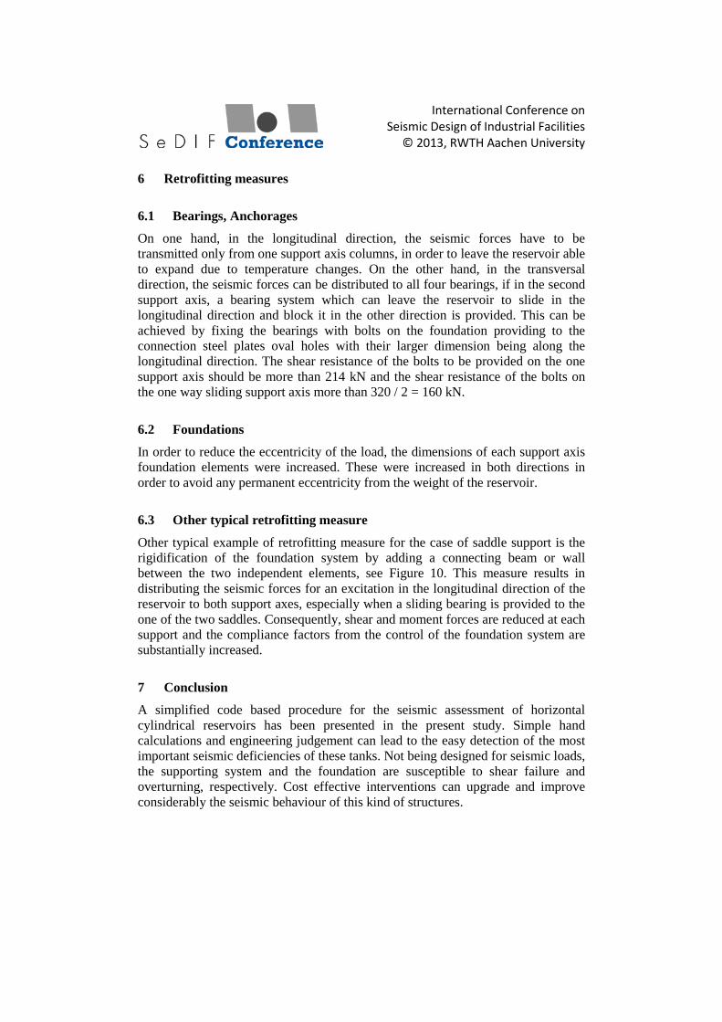
The total seismic force in the transversal and the longitudinal direction is 320 kN and 214 kN, respectively. Indicatively, the seismic forces of each component as well as the total corresponding reactions in the columns are shown in Figure 9 for the case of the excitation in the transversal direction.
Figure 9: Seismic forces in the transversal direction.
The connection between the tank bearings and the foundation has been assumed articulated at one axis and free to slide in both directions at the second axis of support. The supports were assumed fixed at their base.
The control of the bearings showed that the anchor bolts are failing to withstand the seismic forces in both directions. The eccentricity of the load, assuming that the bolts can transmit the seismic forces to the foundation, exceeds the 1/3 of the width of the footing. The same result was obtained in the case the seismic load in the transversal direction is distributed to all four columns. The resistance in sliding has been found adequate due to the connection of the four columns with the slab on grade. The soil stresses due to the large values of eccentricities proved to exceed the soil bearing resistance.
Fds Fdc
Fdi
International Conference on Seismic Design of Industrial Facilities
© 2013, RWTH Aachen University
6 Retrofitting measures
6.1 Bearings, Anchorages
On one hand, in the longitudinal direction, the seismic forces have to be transmitted only from one support axis columns, in order to leave the reservoir able to expand due to temperature changes. On the other hand, in the transversal direction, the seismic forces can be distributed to all four bearings, if in the second support axis, a bearing system which can leave the reservoir to slide in the longitudinal direction and block it in the other direction is provided. This can be achieved by fixing the bearings with bolts on the foundation providing to the connection steel plates oval holes with their larger dimension being along the longitudinal direction. The shear resistance of the bolts to be provided on the one support axis should be more than 214 kN and the shear resistance of the bolts on the one way sliding support axis more than 320 / 2 = 160 kN.
6.2 Foundations
In order to reduce the eccentricity of the load, the dimensions of each support axis foundation elements were increased. These were increased in both directions in order to avoid any permanent eccentricity from the weight of the reservoir.
6.3 Other typical retrofitting measure
Other typical example of retrofitting measure for the case of saddle support is the rigidification of the foundation system by adding a connecting beam or wall between the two independent elements, see Figure 10. This measure results in distributing the seismic forces for an excitation in the longitudinal direction of the reservoir to both support axes, especially when a sliding bearing is provided to the one of the two saddles. Consequently, shear and moment forces are reduced at each support and the compliance factors from the control of the foundation system are substantially increased.
7 Conclusion
A simplified code based procedure for the seismic assessment of horizontal cylindrical reservoirs has been presented in the present study. Simple hand calculations and engineering judgement can lead to the easy detection of the most important seismic deficiencies of these tanks. Not being designed for seismic loads, the supporting system and the foundation are susceptible to shear failure and overturning, respectively. Cost effective interventions can upgrade and improve considerably the seismic behaviour of this kind of structures.

International Conference on Seismic Design of Industrial Facilities
© 2013, RWTH Aachen University
Figure 10: Other typical retrofitting measure.
REFERENCES
[1] Carluccio, A.D. et al.: Analysis of pressurized horizontal vessels under seismic excitation; in China: Proceedings of 14th Conference on Earthquake Engineering; 2008.
[2] European committee for Standardization: Part 1-General rules-seismic actions and rules for buildings; Eurocode 8, Design provisions for earthquake resistance of structures; 2004.
[3] European committee for Standardization: Basis of structural design; Eurocode 0; 2002.
[4] European committee for Standardization: Part 4- Silos, tanks and pipelines; Eurocode 8, Design provisions for earthquake resistance of structures; 2006.
[5] Karamanos, S.A. et al.: Sloshing Effects on the Seismic Design of Horizontal-Cylindrical and Spherical Industrial Vessels; Journal of Pressure Vessel Technology; Vol.128 No.3 (2006), Pages 328-340.
[6] European committee for Standardization: Part 1- General rules; Eurocode 7, Geotechnical design; 2004.
[7] Gazetas, G.: Seismic Design of foundations and soil-structure interaction; in Geneva, Switzerland: Proceedings of 1st European Conference on Earthquake Engineering and Seismology; 2006.
[8] Swiss society of engineers and architects: Actions on structures; SIA 261; 2003.
[Web-1] http://www.michigan.gov/documents/Vol2-5UIP11Tanks_121080_7.pdf , publisher: Michigan state, data gathered on 28. Apr. 2013.
[Web-2] http://www.crealp.ch/phocadownload/Carte_MSS-Chablais_8nov11.pdf, publisher: CREALP, data gathered on 28. Apr. 2013.
new element