section 35 chapter 2 - dmcpubs.com · hitch system plumbing layout ri02e011 1. hitch cylinder right...
TRANSCRIPT

Section 35
Chapter 2
6-12801NH
HYDRAULIC SYSTEM HOW IT WORKS AND TROUBLESHOOTING
SECTION 35 - HYDRAULIC SYSTEM HOW IT WORKS AND TROUBLESHOOTING - CHAPTER 2
35-2
TABLE OF CONTENTS
GENERAL INTRODUCTION .............................................................................................................................. 35-3Hydraulic Pumps ............................................................................................................................................. 35-3Standard Flow PFC Pump Layout .................................................................................................................. 35-5MegaFlow PFC Pump Layout ......................................................................................................................... 35-6Charge Pump Layout ...................................................................................................................................... 35-7Lubrication Circuit ........................................................................................................................................... 35-8Regulated Pressure Circuits ......................................................................................................................... 35-10Steering And Brake Tube Layout .................................................................................................................. 35-12Brake Valve Plumbing Layout ....................................................................................................................... 35-13Hitch System Plumbing Layout ..................................................................................................................... 35-14Power Beyond Layout ................................................................................................................................... 35-15Motor Return Layout ..................................................................................................................................... 35-16
REAR CHARGE/LUBE PUMP PRESSURE TEST .......................................................................................... 35-17
REGULATED SYSTEM PRESSURE TEST AND ADJUSTMENT PROCEDURE ........................................... 35-19
FRONT/REGULATED SYSTEM PUMP FLOW TEST ..................................................................................... 35-23
STEERING RELIEF PRESSURE TEST AND ADJUSTMENT PROCEDURE ................................................. 35-25
STEERING SYSTEM PROBLEMS .................................................................................................................. 35-27
PRIORITY AND REGULATOR VALVE ............................................................................................................ 35-29Priority Spool (Supplied By PFC Piston Pump) ............................................................................................ 35-29Regulator Spool (Supplied By Regulated Pump Section) ............................................................................. 35-29Steering Relief Valve .................................................................................................................................... 35-30
PFC AXIAL PISTON PUMP ............................................................................................................................. 35-32Principal of Control ........................................................................................................................................ 35-32Operating Modes .......................................................................................................................................... 35-32Low Pressure Standby .................................................................................................................................. 35-32Pressure and Flow Delivery and Compensation ........................................................................................... 35-32PFC Axial Piston Pump - Operation .............................................................................................................. 35-34Pressure and Flow Delivery and Compensation Principle ............................................................................ 35-36Increased Flow Demand ............................................................................................................................... 35-36Decreased Flow Demand ............................................................................................................................. 35-37High Pressure Standby ................................................................................................................................. 35-39
STANDARD PFC PUMP HIGH PRESSURE STANDBY CHECK AND ADJUSTMENT PROCEDURE .......... 35-42
STANDARD PFC PISTON PUMP FLOW TEST .............................................................................................. 35-43
STANDARD PFC PISTON PUMP FLOW COMPENSATOR SETTING ........................................................... 35-44Preparation ................................................................................................................................................... 35-44
STANDARD PUMP COMPENSATOR VALVE INSPECTION .......................................................................... 35-46
PFC PUMP OPERATIONAL PROBLEMS ....................................................................................................... 35-47
SECTION 35 - HYDRAULIC SYSTEM HOW IT WORKS AND TROUBLESHOOTING - CHAPTER 2
35-3
GENERAL INTRODUCTION
The tractor uses three hydraulic pumps (four pumps if equipped with MegaFlow) which are driven through a drivehousing on the right side of the range transmission. The pump drive housing gears are driven by the PTO drivelineand all the pumps turn at approximately 1.33 times engine speed. A PFC piston pump is attached to the front of thepump drive housing while the tandem gear pumps are attached to the rear of the pump drive housing. Whenequipped, the MegaFlow piston pump is driven off the back of the dual gear pumps.
The front section of the tandem gear pump is used to supply the regulated pressure circuit: brake valve,transmission control valves, PTO and Diff lock, auxiliary and hitch valve pilot circuits. The rear section suppliescharge flow to the PFC pumps. The PFC pump supplies flow to the priority valve which directs flow to the steeringsystem, remote auxiliary valves and, if equipped, the three point hitch (TPH).
When equipped with MegaFlow a second PFC piston pump system supplies the third, fourth and fifth remotecircuits. The standard PFC piston pump supplies the first and second remote circuits. The two PFC piston pumpcircuits are completely independent of each other.
All hydraulic lines are equipped with O-ring face seals to ensure reliable, vibration resistant connections.
Hydraulic Pumps
Charge/Lubrication Pump
The charge/lubrication pump is the rear section of the dual gear pump and it is used to supply the main PFC pumpwith a charged inlet condition to prevent cavitation. The pump also supplies lubrication and cooling requirementsfor the transmission.
The pump draws oil from the transmission housing through a 100 mesh suction screen. The pump flow is directedacross the main filter assembly to provide clean charge and lubrication oil.
The pump flow rate at rated speed 2667 RPM (2000 RPM engine speed) is:177 L/min (47 US GPM)
Regulated Circuit Pump
The regulated circuit pump is the front section of the tandem gear pump. The pump draws oil from the systemreservoir through a 100 mesh suction screen. The pump flow passes through the regulated circuit filter housingand into the priority regulator valve. The priority regulator valve maintains the regulated pressure circuit at 23 to 24bar (335 to 345 PSI). The regulated pump flow supplies the PTO/ Diff lock valve, transmission control valves andbrake valve. Both the remote and hitch valves are also supplied with regulated pressure.
Once these circuits are satisfied the excess regulated pump flow is directed through the oil coolers and joins upwith the charge pump flow at the downstream side of the main filter head.
The pump flow rate at rated speed 2667 RPM (2000 engine RPM) is:102 L/min (27 GPM)
Standard PFC Piston Pump
The axial piston pump has a variable flow output and can operate at variable pressures.The pump matches thehydraulic power output to the actual load requirements to ensure maximum efficiency and the minimum use of fuel.
SECTION 35 - HYDRAULIC SYSTEM HOW IT WORKS AND TROUBLESHOOTING - CHAPTER 2
35-4
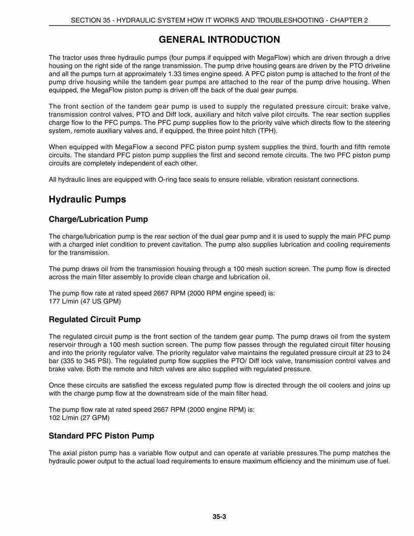
The pump inlet is charged to prevent cavitation. The pump output flow is supplied to the priority regulator valve.The priority regulator valve gives top priority to the steering system and trailer brake circuit. Once the steeringsystem and trailer brake circuits are satisfied the priority regulator valve supplies pump flow to the remote auxiliaryvalves and three point hitch valve.
The maximum pump flow rate at rated speed 2667 RPM (2000 engine speed) is:142 L/min (37.5 GPM)
Optional MegaFlow PFC Piston Pump
The axial piston pump has a variable flow output and can operate at variable pressures.The pump matches thehydraulic power output to the actual load requirements to ensure maximum efficiency and the minimum use of fuel.
The pump inlet is charged to prevent cavitation. The pump output flow is supplied directly to the remote auxiliarymanifold. The manifold is equipped with internal plugs to separate the MegaFlow supply flow, signal line pressureand signal line pilot relief from the standard PFC piston pump circuit. The MegaFlow pump supplies only the third,fourth or fifth remote sections. The two PFC pump hydraulic circuits operate independently.
The maximum pump flow rate at rated speed 2667 RPM (2000 engine speed) is:111 L/min (29.4 GPM)
RI02D121
1. CHARGE/LUBRICATION PUMP OUTLET (REAR SECTION)
4. DUAL GEAR PUMP/ REGULATED SYSTEM FILTER HOUSING
2. REGULATED CIRCUIT PUMP OUTLET (FRONT SECTION)
5. MAIN FILTER ASSEMBLY
3. PFC PISTON PUMP 6. MEGAFLOW PFC PISTON PUMP
1
2
4
3
5
6
SECTION 35 - HYDRAULIC SYSTEM HOW IT WORKS AND TROUBLESHOOTING - CHAPTER 2
35-5
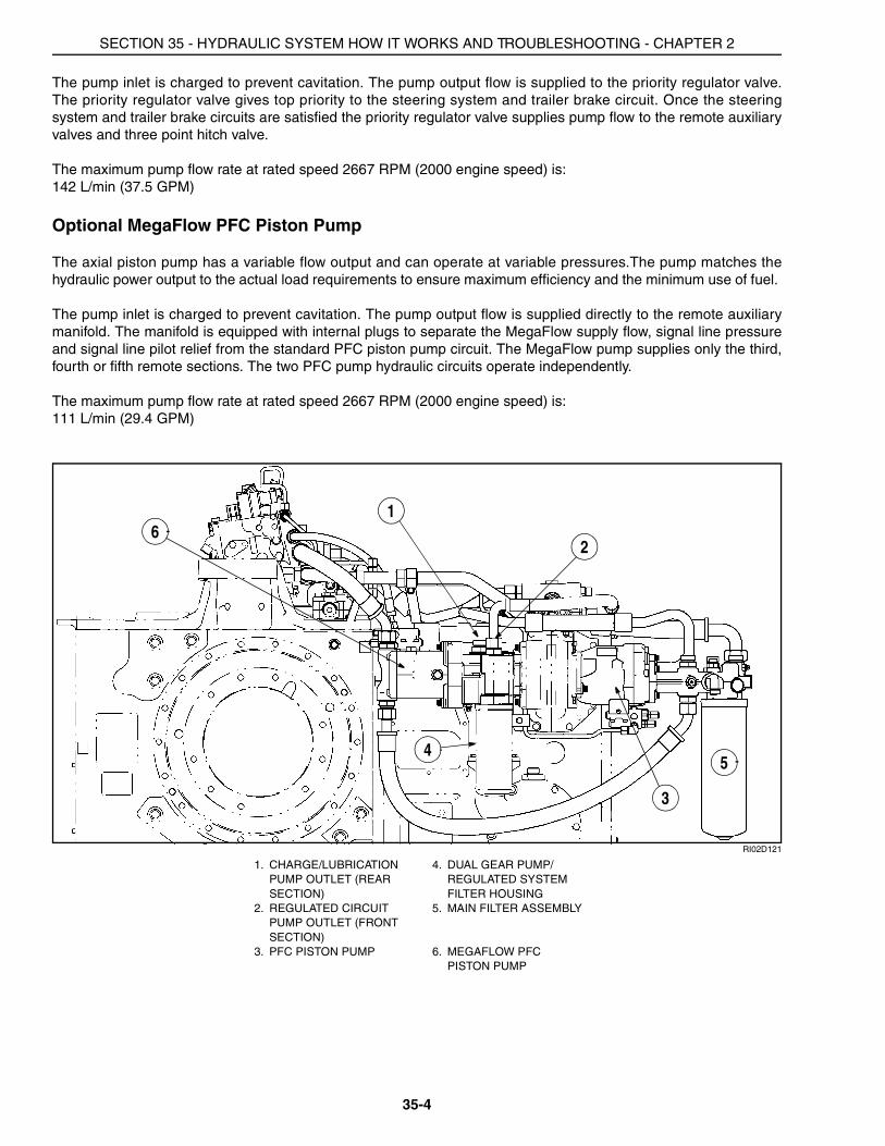
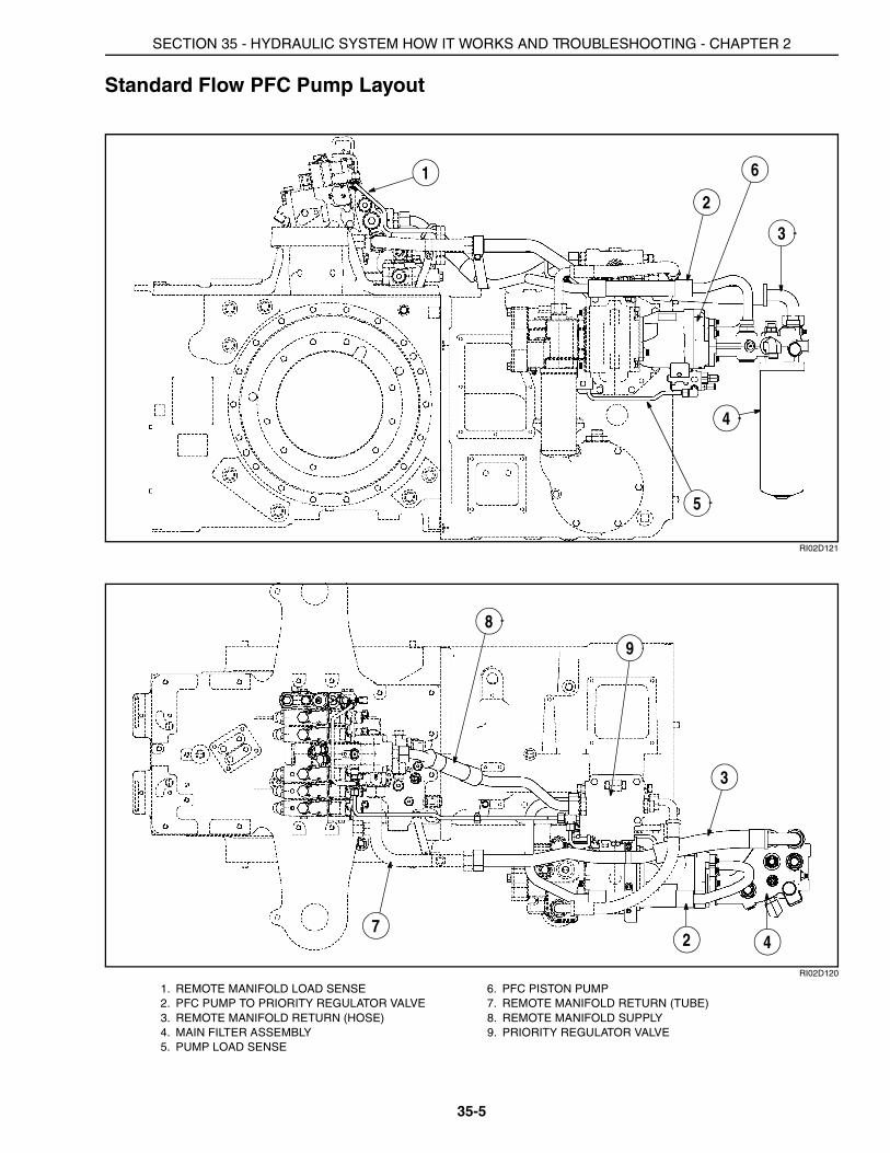
Standard Flow PFC Pump Layout
RI02D121
RI02D120
1. REMOTE MANIFOLD LOAD SENSE 6. PFC PISTON PUMP2. PFC PUMP TO PRIORITY REGULATOR VALVE 7. REMOTE MANIFOLD RETURN (TUBE)3. REMOTE MANIFOLD RETURN (HOSE) 8. REMOTE MANIFOLD SUPPLY4. MAIN FILTER ASSEMBLY 9. PRIORITY REGULATOR VALVE5. PUMP LOAD SENSE
1
2
3
4
5
6
4
3
27
8
9
SECTION 35 - HYDRAULIC SYSTEM HOW IT WORKS AND TROUBLESHOOTING - CHAPTER 2
35-6
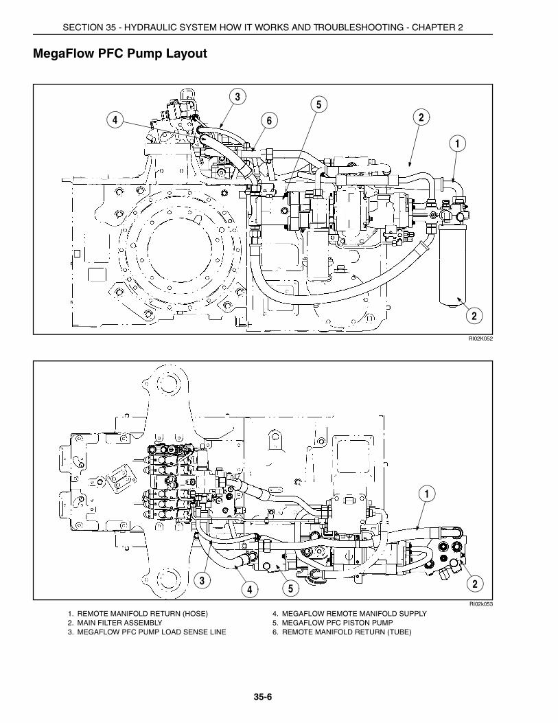
MegaFlow PFC Pump Layout
RI02K052
RI02k053
1. REMOTE MANIFOLD RETURN (HOSE) 4. MEGAFLOW REMOTE MANIFOLD SUPPLY2. MAIN FILTER ASSEMBLY 5. MEGAFLOW PFC PISTON PUMP3. MEGAFLOW PFC PUMP LOAD SENSE LINE 6. REMOTE MANIFOLD RETURN (TUBE)
6 2
1
2
53
4
1
234 5
SECTION 35 - HYDRAULIC SYSTEM HOW IT WORKS AND TROUBLESHOOTING - CHAPTER 2
35-7
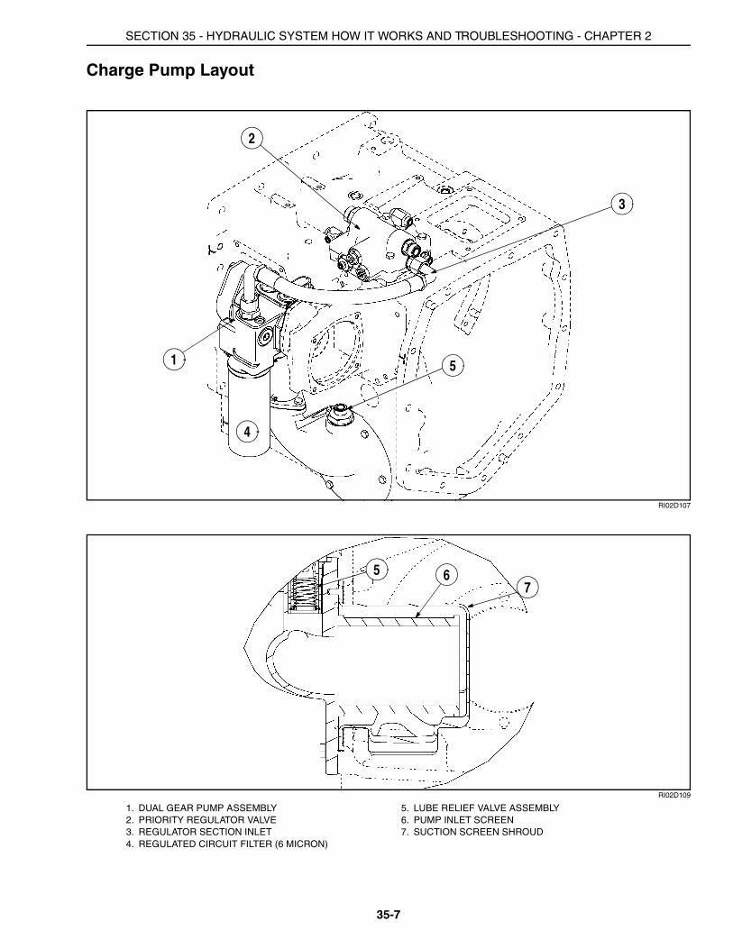
Charge Pump Layout
RI02D107
RI02D109
1. DUAL GEAR PUMP ASSEMBLY 5. LUBE RELIEF VALVE ASSEMBLY2. PRIORITY REGULATOR VALVE 6. PUMP INLET SCREEN3. REGULATOR SECTION INLET 7. SUCTION SCREEN SHROUD4. REGULATED CIRCUIT FILTER (6 MICRON)
2
3
4
51
5 67
SECTION 35 - HYDRAULIC SYSTEM HOW IT WORKS AND TROUBLESHOOTING - CHAPTER 2
35-8
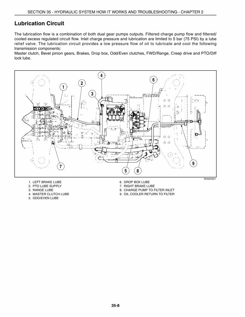
Lubrication Circuit
The lubrication flow is a combination of both dual gear pumps outputs. Filtered charge pump flow and filtered/cooled excess regulated circuit flow. Inlet charge pressure and lubrication are limited to 5 bar (75 PSI) by a luberelief valve. The lubrication circuit provides a low pressure flow of oil to lubricate and cool the followingtransmission components:Master clutch, Bevel pinion gears, Brakes, Drop box, Odd/Even clutches, FWD/Range, Creep drive and PTO/Difflock lube.
RH02H0511. LEFT BRAKE LUBE 6. DROP BOX LUBE2. PTO LUBE SUPPLY 7. RIGHT BRAKE LUBE3. RANGE LUBE 8. CHARGE PUMP TO FILTER INLET4. MASTER CLUTCH LUBE 9. OIL COOLER RETURN TO FILTER5. ODD/EVEN LUBE
12
3
4
5
6
78
9

SECTION 35 - HYDRAULIC SYSTEM HOW IT WORKS AND TROUBLESHOOTING - CHAPTER 2
35-9
RH02H052
RH02H053
7. RIGHT BRAKE LUBE 10. LUBE RELIEF HOSE
11. DROP BOX OUTPUT LUBE (WITHOUT CREEPER) 12. DROP BOX REAR BEARING LUBE
107
12
11

SECTION 35 - HYDRAULIC SYSTEM HOW IT WORKS AND TROUBLESHOOTING - CHAPTER 2
35-10
Regulated Pressure Circuits
The regulated circuit is supplied by the front dual gear pump. The pump flow passes through the regulated circuitfilter housing and onto the priority regulator valve. The pressure regulator portion of the valve maintains theregulated pressure at 23 to 24 bar (335 to 345 PSI). The following components are supplied by the regulatedcircuit:Speed transmission powershift valve, Odd/Even transmission powershift valve (includes creep and park brake),Range transmission powershift valve (includes FWD), PTO/Diff lock valve, Master clutch inching valve, Brakevalve, Hitch valve pilot pressure, Remote valve pilot pressure and FWD clutch supply
RI02G037
NOTE: Brake, hitch and remote valves regulated supply tubes not shown. See brake, hitch and remote circuits inthis section.
1. RANGE REGULATED SUPPLY TUBE 6. MASTER CLUTCH DIAGNOSTIC COUPLER2. SPEED TRANSMISSION CONTROL VALVE
REGULATED SUPPLY-UPPER TUBE7. TRANSMISSION CONTROL VALVE
REGULATED SUPPLY3. PRIORITY REGULATOR VALVE TO PTO
VALVE8. PRIORITY REGULATOR VALVE EXCESS TO
OIL COOLERS4. PRIORITY REGULATOR VALVE 9. REGULATED CIRCUIT ACCUMULATOR5. MASTER CLUTCH DIAGNOSTIC TUBE 10. SPEED TRANSMISSION CONTROL VALVE
REGULATED SUPPLY-LOWER TUBE
1 2
34
5
78
SECTION 35 - HYDRAULIC SYSTEM HOW IT WORKS AND TROUBLESHOOTING - CHAPTER 2
35-11
RI02G038
RI02G039
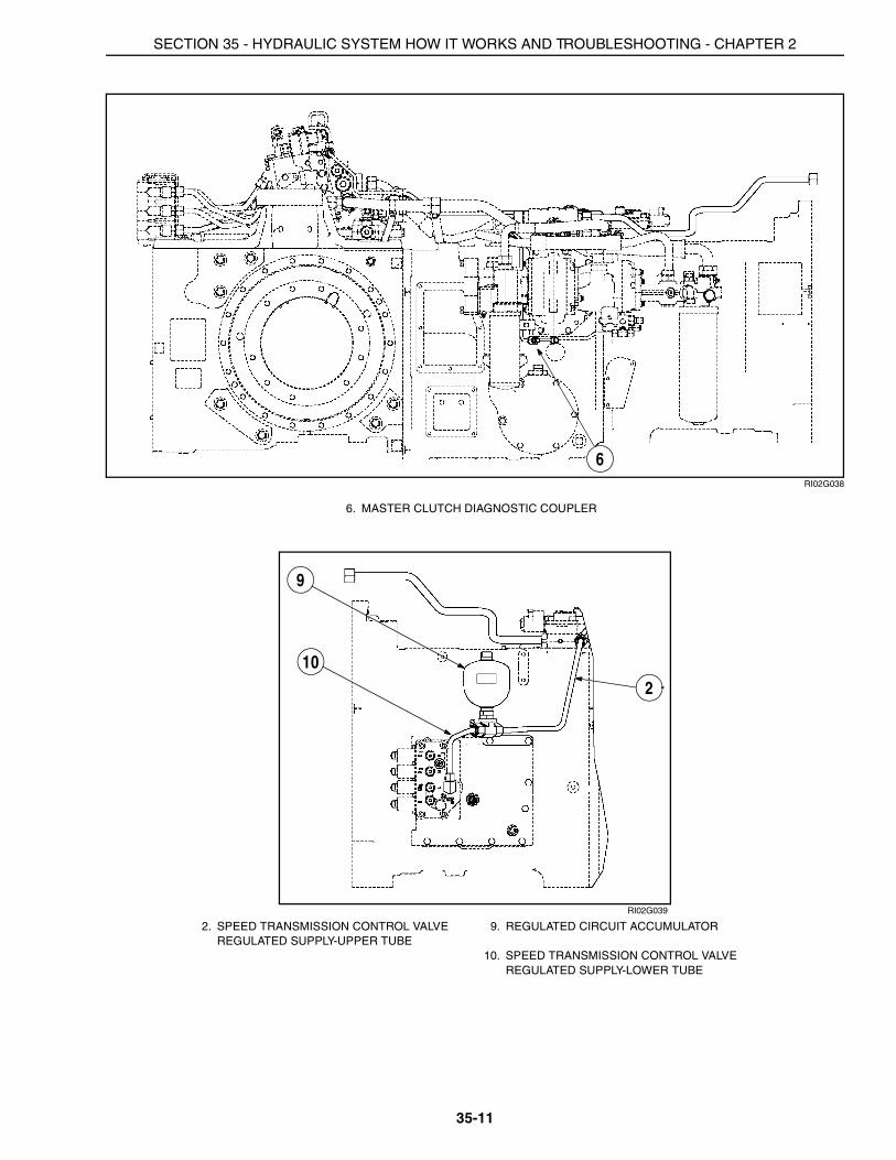
6. MASTER CLUTCH DIAGNOSTIC COUPLER
2. SPEED TRANSMISSION CONTROL VALVE REGULATED SUPPLY-UPPER TUBE
9. REGULATED CIRCUIT ACCUMULATOR
10. SPEED TRANSMISSION CONTROL VALVE REGULATED SUPPLY-LOWER TUBE
6
9
102
SECTION 35 - HYDRAULIC SYSTEM HOW IT WORKS AND TROUBLESHOOTING - CHAPTER 2
35-12
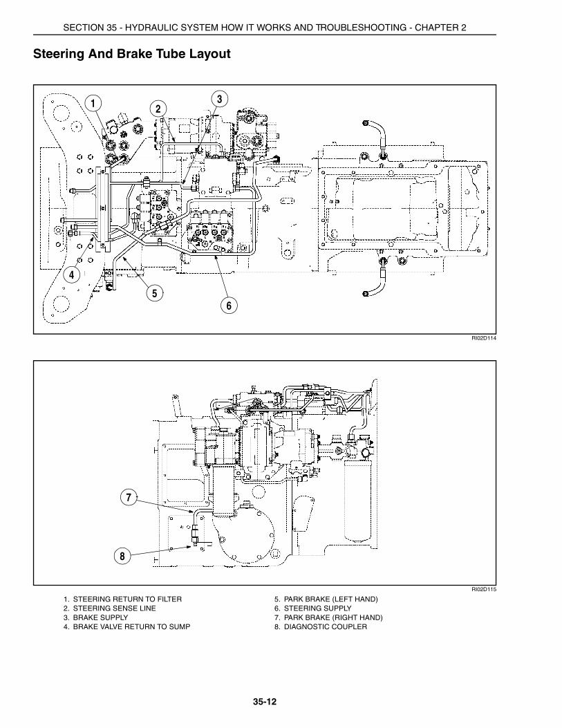
Steering And Brake Tube Layout
RI02D114
RI02D115
1. STEERING RETURN TO FILTER 5. PARK BRAKE (LEFT HAND)2. STEERING SENSE LINE 6. STEERING SUPPLY3. BRAKE SUPPLY 7. PARK BRAKE (RIGHT HAND)4. BRAKE VALVE RETURN TO SUMP 8. DIAGNOSTIC COUPLER
3
5
1 2
4
6
7
8

SECTION 35 - HYDRAULIC SYSTEM HOW IT WORKS AND TROUBLESHOOTING - CHAPTER 2
35-13
Brake Valve Plumbing Layout
RI02D113
1. BRAKE VALVE RETURN TO SUMP 5. BRAKE SUPPLY TUBE (RIGHT SIDE)2. BRAKE HOSE (RIGHT SIDE) 6. BRAKE SUPPLY TUBE (LEFT SIDE)3. BRAKE VALVE SUPPLY 7. BRAKE VALVE4. BRAKE HOSE (LEFT SIDE)
3
1
2
5 6
4
7
SECTION 35 - HYDRAULIC SYSTEM HOW IT WORKS AND TROUBLESHOOTING - CHAPTER 2
35-14
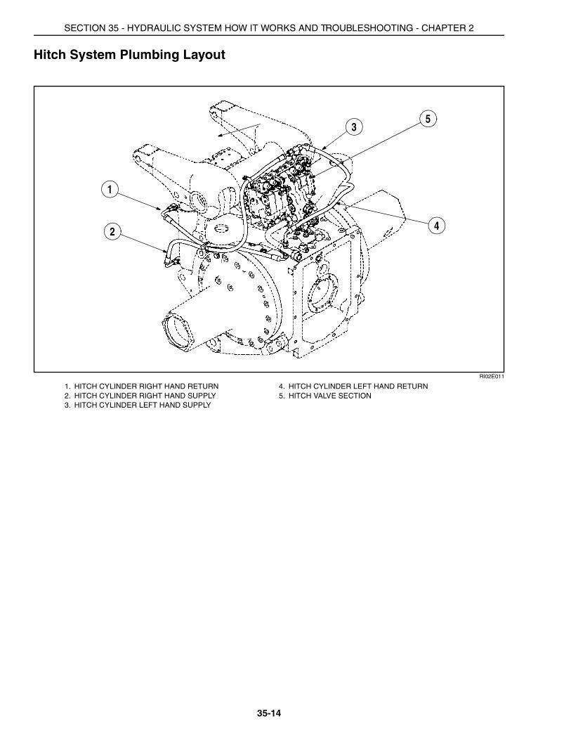
Hitch System Plumbing Layout
RI02E011
1. HITCH CYLINDER RIGHT HAND RETURN 4. HITCH CYLINDER LEFT HAND RETURN2. HITCH CYLINDER RIGHT HAND SUPPLY 5. HITCH VALVE SECTION3. HITCH CYLINDER LEFT HAND SUPPLY
1
2
3
4
5

SECTION 35 - HYDRAULIC SYSTEM HOW IT WORKS AND TROUBLESHOOTING - CHAPTER 2
35-15
Power Beyond Layout
RI02D103
RI02D105 AND RH02J002
NOTE: Remove internal plug (9) to maintain high pressure standby condition.
1. POWER BEYOND LOAD SENSE TUBE 7. POWER BEYOND RETURN FLOW COUPLER2. POWER BEYOND SUPPLY TUBE 8. CHECK VALVE 3. POWER BEYOND RETURN TUBE 9. INTERNAL PLUG4. CASE DRAIN 10. EXTERNAL PLUG5. LOAD SENSE COUPLER 11. VALVE ASSEMBLY PILOT RELIEF6. POWER BEYOND COUPLER (SUPPLY)
1
2
3
45
6
7
10
10
8
9
32
11
SECTION 35 - HYDRAULIC SYSTEM HOW IT WORKS AND TROUBLESHOOTING - CHAPTER 2
35-16
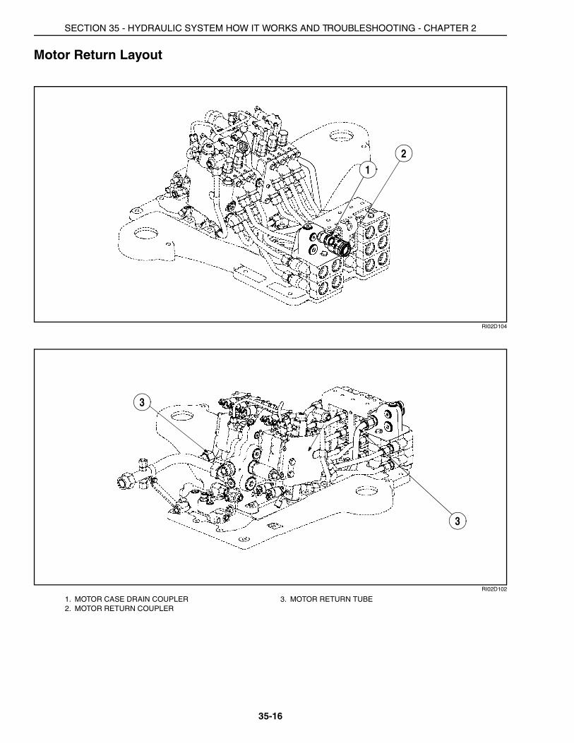
Motor Return Layout
RI02D104
RI02D102
1. MOTOR CASE DRAIN COUPLER 3. MOTOR RETURN TUBE2. MOTOR RETURN COUPLER
12
3
3
SECTION 35 - HYDRAULIC SYSTEM HOW IT WORKS AND TROUBLESHOOTING - CHAPTER 2
35-17
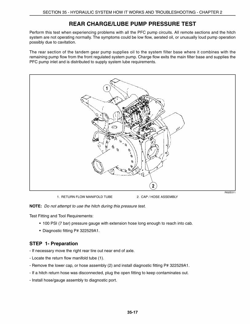
REAR CHARGE/LUBE PUMP PRESSURE TESTPerform this test when experiencing problems with all the PFC pump circuits. All remote sections and the hitchsystem are not operating normally. The symptoms could be low flow, aerated oil, or unusually loud pump operationpossibly due to cavitation.
The rear section of the tandem gear pump supplies oil to the system filter base where it combines with theremaining pump flow from the front regulated system pump. Charge flow exits the main filter base and supplies thePFC pump inlet and is distributed to supply system lube requirements.
RI02E011
NOTE: Do not attempt to use the hitch during this pressure test.
Test Fitting and Tool Requirements:
• 100 PSI (7 bar) pressure gauge with extension hose long enough to reach into cab.
• Diagnostic fitting P# 322529A1.
STEP 1- Preparation- If necessary move the right rear tire out near end of axle.
- Locate the return flow manifold tube (1).
- Remove the lower cap, or hose assembly (2) and install diagnostic fitting P# 322529A1.
- If a hitch return hose was disconnected, plug the open fitting to keep contaminates out.
- Install hose/gauge assembly to diagnostic port.
1. RETURN FLOW MANIFOLD TUBE 2. CAP / HOSE ASSEMBLY
1
2
SECTION 35 - HYDRAULIC SYSTEM HOW IT WORKS AND TROUBLESHOOTING - CHAPTER 2
35-18
STEP 2- Charge Pressure Measurement- Place the transmission control lever in the “P” park position.
- Start and run the engine at low idle.
- Heat the transmission oil to a minimum of 120°F (50°C).
- Place a piece of cardboard over the oil cooler to heat the oil.
- Increase the engine speed to 2000 RPM. Record the charge pressure____________
Charge Pressure Specification: 50 PSI (3.4 bar) Minimum at 2000 RPM engine speed
A. If the correct charge pressure was obtained, the charge system is functioning correctly.
B. If the charge pressure is less than 50 PSI (3.4 bar) check for the following:
Low oil level in transmission.
Lube relief valve spring broke or poppet stuck open.
Inlet suction screen may be plugged. You must drain transmission.
Air leaks on suction side of pump. (Is hydraulic oil aerated?)
Low charge pump flow.
Low regulated pump flow. See Regulated System Pressure Test in this section.
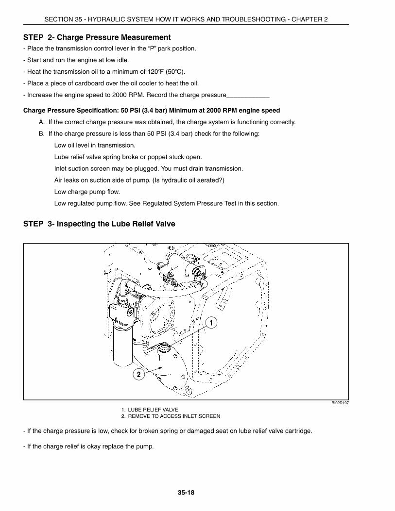
STEP 3- Inspecting the Lube Relief Valve
RI02D107
- If the charge pressure is low, check for broken spring or damaged seat on lube relief valve cartridge.
- If the charge relief is okay replace the pump.
1. LUBE RELIEF VALVE2. REMOVE TO ACCESS INLET SCREEN
1
2

SECTION 35 - HYDRAULIC SYSTEM HOW IT WORKS AND TROUBLESHOOTING - CHAPTER 2
35-19
REGULATED SYSTEM PRESSURE TEST AND ADJUSTMENT PROCEDURE
Perform this test to verify the condition of the regulated system before adjusting the regulated pressure. Lowregulated pressure can cause clutches to slip, hinder remote and hitch operation and decrease brakeeffectiveness. Even if the regulated pressure meets the specification, there could be substantial leakage in one ofthe regulated circuit functions that is not in use. The regulated system leakage test is designed to locate regulatedcircuit leakage paths. The 27 GPM front gear pump is a fixed displacement pump, therefore as engine speed isdecreased the pump outlet flow will decrease. At lower engine speeds leaks in the regulated circuit are morenoticeable.
The front section of the tandem gear pump supplies oil flow to the steering priority/regulator valve. The pressureregulator section of the valve maintains the regulated pressure circuit at 335 to 345 PSI (23 to 24 bar) The followingcircuits are supplied (FWD, PTO, Park Brake, Diff Lock, Transmission Control Valves, Service Brakes along withthe Hitch and Remote valve pilot circuits). When the demand for all these regulated circuits is met all the remainingfront pump flow is directed through the oil cooler and then to the filter base.
STEP 1- Regulated Pressure Check with the Tractor Monitor
NOTE: Start the engine and heat the transmission oil to 120°F (49°C).
- Place a piece of cardboard over oil cooler to heat the oil.
- Turn the ignition switch to the OFF position. Be prepared to press and hold the PROG key on the Tractor Monitorwithin the first 10 seconds after restarting the engine.
- Start and run the engine at low idle. Press and hold the PROG key
- The tractor monitor will emit a short beep and display INST SET MENU. Press the DECR key until the displayreads TRANS SET MENU.
- Next press the PROG key until the display reads TRANS VIEW.
- Now press the DECR key until the display reads PRES TRNSDCR.
- Press the PROG key.
- The powershift system manifold pressure (in KPa) is now visible on the bottom of the display.
- Record pressure with the PTO and Diff Lock in the OFF position and the FWD switch in the ON position.
- Increase engine speed to 1500 RPM. Record the range powershift manifold pressure. Decrease engine speed.
• The “PresS” - Powershift System Manifold Pressure______________kPa at 1500 RPM
A. If the pressure reading is less than 300 PSI (20.7 bar) go to the regulated pump flow test.
B. If the pressure reading is greater than 300 PSI (20.7 bar) go to the regulated system leakage test.(Complete the regulated system leakage test before adjusting the regulated pressure).
NOTE: Transducer Pressure Range: 2300 to 2400 kPa (335 to 345 PSI) at 1500 RPM and 120°F (49°C). To convert kPa tobar move the decimal place over two places to left, 2300 kPa equals 23.0 bar.
SECTION 35 - HYDRAULIC SYSTEM HOW IT WORKS AND TROUBLESHOOTING - CHAPTER 2
35-20
STEP 2- Regulated System Leakage Test
A regulated system leak can be identified by a slight drop in regulated pressure at low engine RPM. As a regulatedcircuit is engaged and disengaged the pressure reading on the gauge will dip slightly as each circuit is actuated.
IMPORTANT: If the regulated pressure did not dip as a circuit is actuated then that circuit is not functioning.Inspect the solenoid valve, electrical system connections and circuit fault codes for that system before proceeding.
- Heat the transmission oil to 120°F (50°C).
- Start testing with the PTO and Diff Lock in the OFF position and the FWD switch in the ON position.
- Maintain the engine speed at 1000 RPM and record the pressure displayed on the tractor monitor.
• The Regulated Circuit Baseline Pressure______________kPa at 1000 RPM
Record the regulated pressure as each circuit is engaged. Once the reading is recorded disengage the circuit.
FWD CIRCUIT
A. Turn the FWD OFF and back ON.
Pressure Reading with FWD OFF at 1000 RPM:____________
NOTE: The FWD is spring engaged and hydraulically disengaged, so the pressure reading is taken with the FWDOFF
If the pressure dipped when the circuit was actuated, but does not return to the Regulated Circuit BaselineReading the FWD clutch is leaking.
If the pressure does not dip when the circuit is actuated check the solenoid function and electrical systemconnections. See FWD and Diff Lock System Section and double check for fault codes on the PTOcontroller.
If the pressure dipped when the circuit was actuated and returns to the Regulated Circuit BaselineReading the FWD clutch is okay. Continue with Item B.
NOTE: The FWD and Diff Lock are controlled by PTO controller.
DIFF LOCK CIRCUIT
B. Turn the Diff Lock ON and back OFF.
Pressure Reading with Diff Lock ON at 1000 RPM:____________
If the pressure dipped when the circuit was actuated, but does not return to the Regulated Circuit BaselineReading the Diff Lock clutch is leaking.
If the pressure does not dip when the circuit is actuated check the solenoid function and electrical systemconnections. See FWD and Diff Lock System Section and double check for fault codes on the PTOcontroller.
If the pressure dipped when the circuit was actuated and returns to the Regulated Circuit BaselineReading the Diff Lock clutch is okay. Continue with Item C.
NOTE: The FWD and Diff Lock are controlled by PTO controller.
SECTION 35 - HYDRAULIC SYSTEM HOW IT WORKS AND TROUBLESHOOTING - CHAPTER 2
35-21
PTO CIRCUIT
C. Turn the PTO ON and back OFF.
Pressure Reading with PTO ON at 1000 RPM:____________
If the pressure dipped when the circuit was actuated, but does not return to the Regulated Circuit BaselineReading the PTO clutch is leaking.
If the pressure does not dip when the circuit is actuated check the solenoid function and electrical systemconnections. See PTO System Section and double check for fault codes on the PTO controller.
If the pressure dipped when the circuit was actuated and returns to the Regulated Circuit BaselineReading the PTO clutch is okay. Continue with Item D.
PARK BRAKE CIRCUIT
D. Shift the transmission control lever from PARK to NEUTRAL and back to PARK.
Pressure Reading with transmission control lever in NEUTRAL at 1000 RPM:____________
NOTE: The Park Brake is spring engaged and hydraulically disengaged, so the pressure reading is taken with thetransmission control lever in NEUTRAL.
If the pressure dipped when the circuit was actuated, but does not return to the Regulated Circuit BaselineReading the Park Brake clutch is leaking.
If the pressure does not dip when the circuit is actuated check the solenoid function and electrical systemconnections. See Park Brake System Section.
If the pressure dipped when the circuit was actuated and returns to the Regulated Circuit BaselineReading the Park Brake clutch is okay. Continue with Step 3.
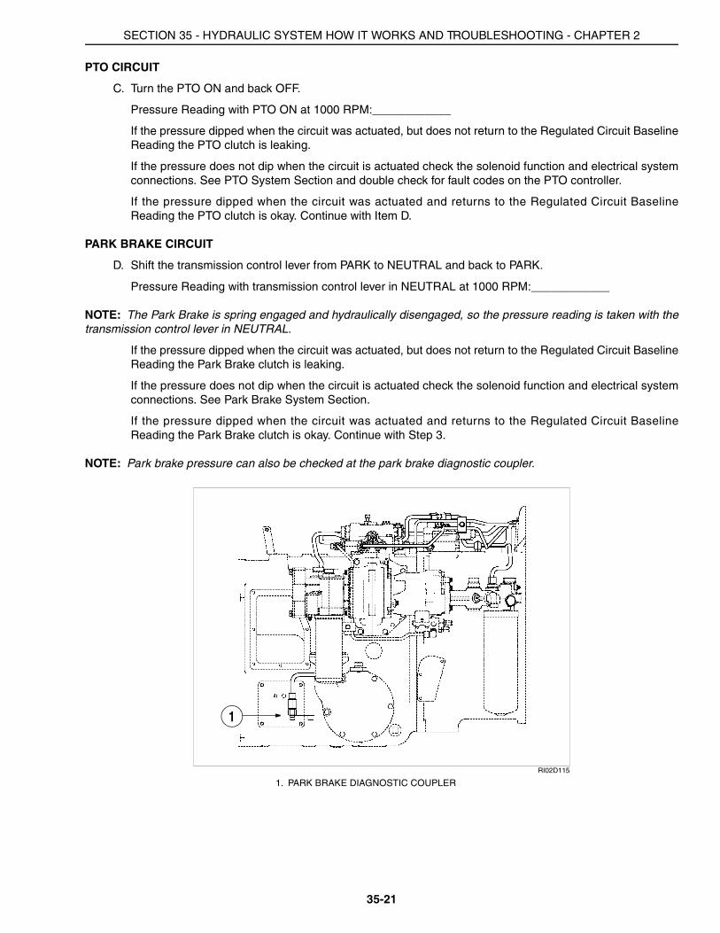
NOTE: Park brake pressure can also be checked at the park brake diagnostic coupler.
RI02D115
1. PARK BRAKE DIAGNOSTIC COUPLER
1
SECTION 35 - HYDRAULIC SYSTEM HOW IT WORKS AND TROUBLESHOOTING - CHAPTER 2
35-22
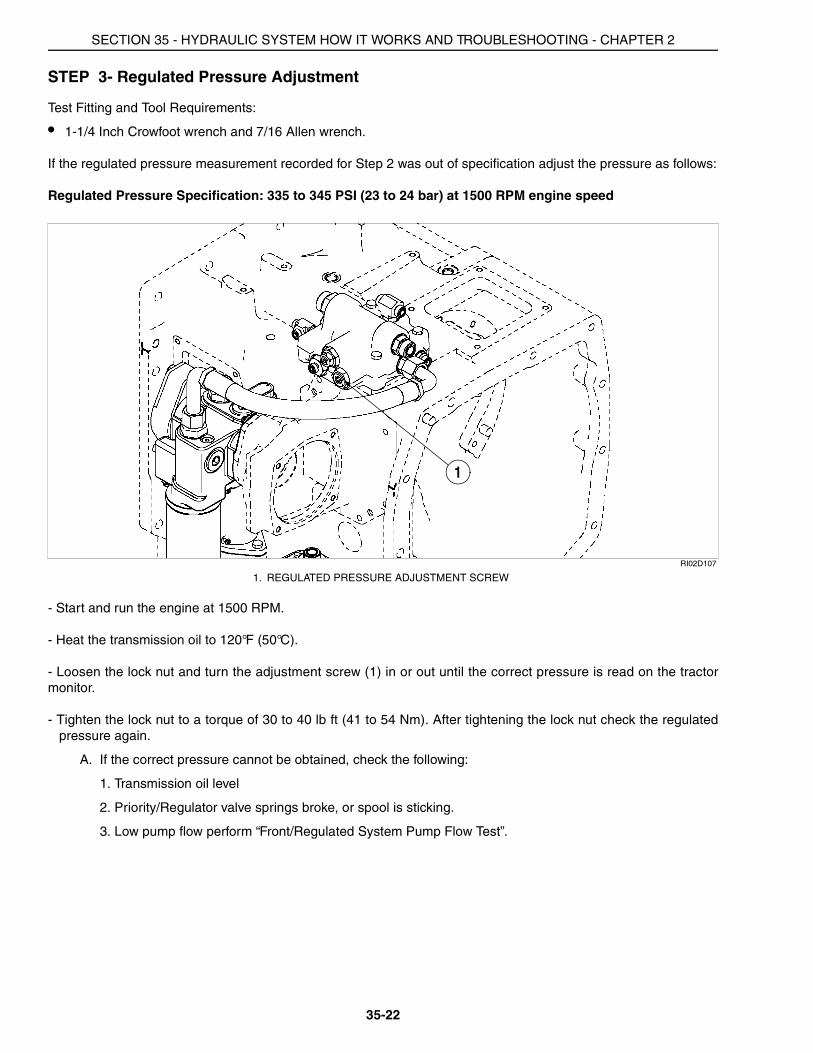
STEP 3- Regulated Pressure Adjustment
Test Fitting and Tool Requirements:
• 1-1/4 Inch Crowfoot wrench and 7/16 Allen wrench.
If the regulated pressure measurement recorded for Step 2 was out of specification adjust the pressure as follows:
Regulated Pressure Specification: 335 to 345 PSI (23 to 24 bar) at 1500 RPM engine speed
RI02D107
- Start and run the engine at 1500 RPM.
- Heat the transmission oil to 120°F (50°C).
- Loosen the lock nut and turn the adjustment screw (1) in or out until the correct pressure is read on the tractormonitor.
- Tighten the lock nut to a torque of 30 to 40 lb ft (41 to 54 Nm). After tightening the lock nut check the regulatedpressure again.
A. If the correct pressure cannot be obtained, check the following:
1. Transmission oil level
2. Priority/Regulator valve springs broke, or spool is sticking.
3. Low pump flow perform “Front/Regulated System Pump Flow Test”.
1. REGULATED PRESSURE ADJUSTMENT SCREW
1
SECTION 35 - HYDRAULIC SYSTEM HOW IT WORKS AND TROUBLESHOOTING - CHAPTER 2
35-23
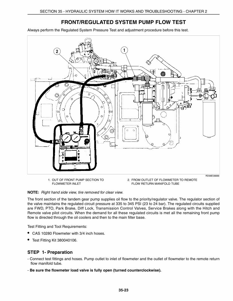
FRONT/REGULATED SYSTEM PUMP FLOW TESTAlways perform the Regulated System Pressure Test and adjustment procedure before this test.
RD98E08888
NOTE: Right hand side view, tire removed for clear view.
The front section of the tandem gear pump supplies oil flow to the priority/regulator valve. The regulator section ofthe valve maintains the regulated circuit pressure at 335 to 345 PSI (23 to 24 bar). The regulated circuits suppliedare FWD, PTO, Park Brake, Diff Lock, Transmission Control Valves, Service Brakes along with the Hitch andRemote valve pilot circuits. When the demand for all these regulated circuits is met all the remaining front pumpflow is directed through the oil coolers and then to the main filter base.
Test Fitting and Tool Requirements:
• CAS 10280 Flowmeter with 3/4 inch hoses.
• Test Fitting Kit 380040106.
STEP 1- Preparation- Connect test fittings and hoses. Pump outlet to inlet of flowmeter and the outlet of flowmeter to the remote return
flow manifold tube.
- Be sure the flowmeter load valve is fully open (turned counterclockwise).
1. OUT OF FRONT PUMP SECTION TO FLOWMETER INLET
2. FROM OUTLET OF FLOWMETER TO REMOTE FLOW RETURN MANIFOLD TUBE
12
SECTION 35 - HYDRAULIC SYSTEM HOW IT WORKS AND TROUBLESHOOTING - CHAPTER 2
35-24
STEP 2- Flow Measurement
NOTE: It is not necessary to heat the hydraulic system for this test, but the system should be near roomtemperature 70 Degrees F (21 Degrees C).
- Place the transmission control lever into “P” park position.
- Start and run the engine at 2000 RPM.
- Adjust the flowmeter load setting to approximately 300 PSI (20.7 bar).
- Record the flow reading:
Front Regulated pump flow reading at 2000 RPM_____________ at 300 PSI (20.7 bar)
Front Regulated Pump flow specification: 27.0 GPM (102.2 L/min) minimum at 2000 RPM.
A. If the pump flow is 24.0 GPM (90.8 L/min) or greater the regulated pump is functioning correctly.
B. If the pump flow is 21.6 to 24.0 GPM (81.8 to 90.8 L/min) the pump output is adequate, but the pumpefficiency is low.
C. If the pump flow is below 21.6 GPM (81.8 L/min) replace the front regulated pump.
SECTION 35 - HYDRAULIC SYSTEM HOW IT WORKS AND TROUBLESHOOTING - CHAPTER 2
35-25
STEERING RELIEF PRESSURE TEST AND ADJUSTMENT PROCEDUREIf excessive effort is required for steering, or steering is slow or sluggish the steering relief valve may be leaking orneed adjustment.
Test Fitting and Tool Requirements:
• 5000 PSI (344 bar) pressure gauge
• Run tee fitting (ORFS) and diagnostic coupler from Test Fitting Kit 380040106.
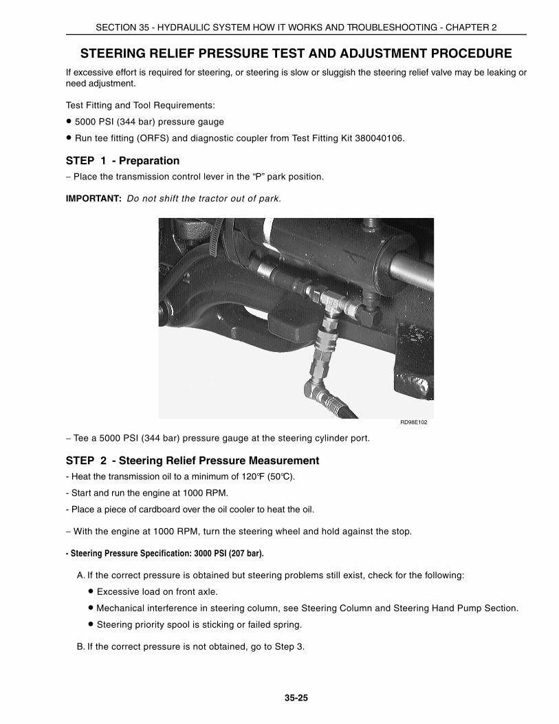
STEP 1 - Preparation− Place the transmission control lever in the “P” park position.
IMPORTANT: Do not shift the tractor out of park.
RD98E102
− Tee a 5000 PSI (344 bar) pressure gauge at the steering cylinder port.
STEP 2 - Steering Relief Pressure Measurement- Heat the transmission oil to a minimum of 120°F (50°C).
- Start and run the engine at 1000 RPM.
- Place a piece of cardboard over the oil cooler to heat the oil.
− With the engine at 1000 RPM, turn the steering wheel and hold against the stop.
- Steering Pressure Specification: 3000 PSI (207 bar).
A. If the correct pressure is obtained but steering problems still exist, check for the following:
• Excessive load on front axle.
• Mechanical interference in steering column, see Steering Column and Steering Hand Pump Section.
• Steering priority spool is sticking or failed spring.
B. If the correct pressure is not obtained, go to Step 3.
SECTION 35 - HYDRAULIC SYSTEM HOW IT WORKS AND TROUBLESHOOTING - CHAPTER 2
35-26
STEP 3 - Steering Relief Pressure Adjustment
Test Fitting and Tool Requirements:
• 1/4 inch Allen wrench
• 15/16 inch wrench
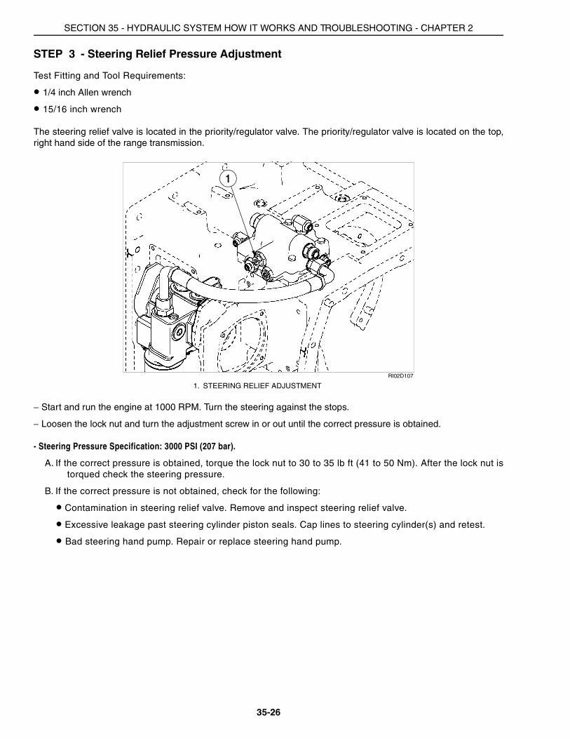
The steering relief valve is located in the priority/regulator valve. The priority/regulator valve is located on the top,right hand side of the range transmission.
RI02D107
− Start and run the engine at 1000 RPM. Turn the steering against the stops.
− Loosen the lock nut and turn the adjustment screw in or out until the correct pressure is obtained.
- Steering Pressure Specification: 3000 PSI (207 bar).
A. If the correct pressure is obtained, torque the lock nut to 30 to 35 lb ft (41 to 50 Nm). After the lock nut istorqued check the steering pressure.
B. If the correct pressure is not obtained, check for the following:
• Contamination in steering relief valve. Remove and inspect steering relief valve.
• Excessive leakage past steering cylinder piston seals. Cap lines to steering cylinder(s) and retest.
• Bad steering hand pump. Repair or replace steering hand pump.
1. STEERING RELIEF ADJUSTMENT
1
SECTION 35 - HYDRAULIC SYSTEM HOW IT WORKS AND TROUBLESHOOTING - CHAPTER 2
35-27
STEERING SYSTEM PROBLEMS
✎
✎
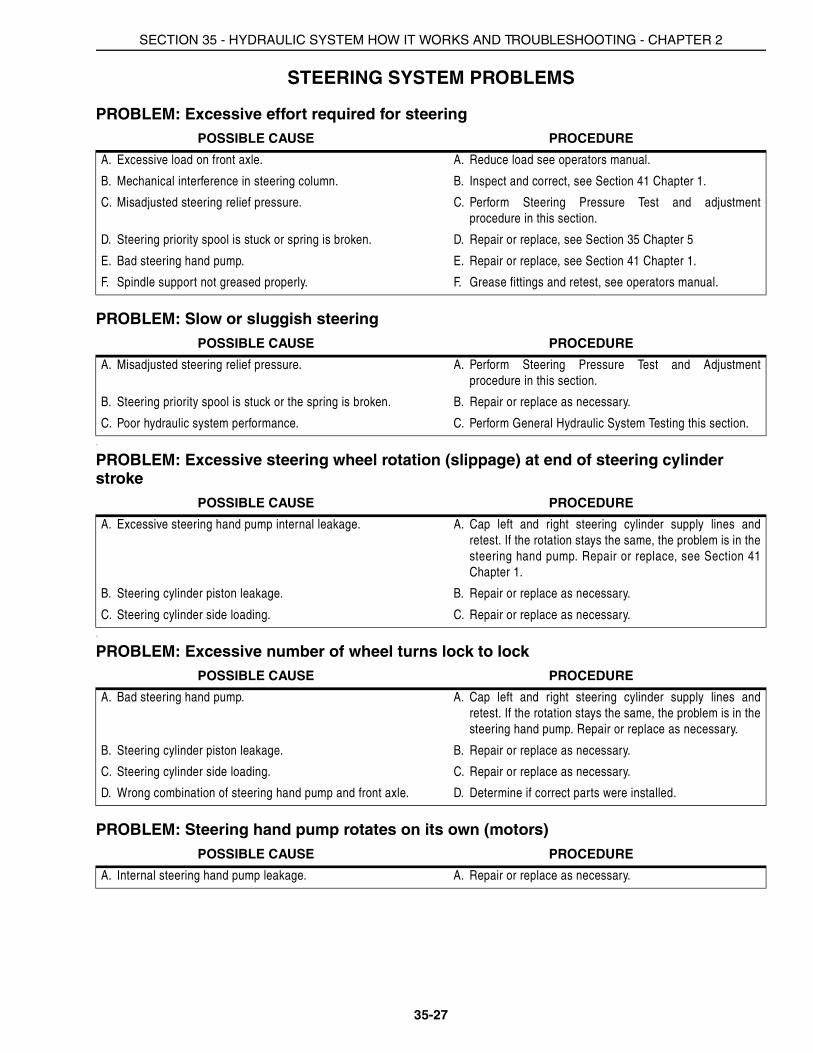
PROBLEM: Excessive effort required for steeringPOSSIBLE CAUSE PROCEDURE
A. Excessive load on front axle. A. Reduce load see operators manual.
B. Mechanical interference in steering column. B. Inspect and correct, see Section 41 Chapter 1.
C. Misadjusted steering relief pressure. C. Perform Steering Pressure Test and adjustmentprocedure in this section.
D. Steering priority spool is stuck or spring is broken. D. Repair or replace, see Section 35 Chapter 5
E. Bad steering hand pump. E. Repair or replace, see Section 41 Chapter 1.
F. Spindle support not greased properly. F. Grease fittings and retest, see operators manual.
PROBLEM: Slow or sluggish steeringPOSSIBLE CAUSE PROCEDURE
A. Misadjusted steering relief pressure. A. Perform Steering Pressure Test and Adjustmentprocedure in this section.
B. Steering priority spool is stuck or the spring is broken. B. Repair or replace as necessary.
C. Poor hydraulic system performance. C. Perform General Hydraulic System Testing this section.
PROBLEM: Excessive steering wheel rotation (slippage) at end of steering cylinder stroke
POSSIBLE CAUSE PROCEDURE
A. Excessive steering hand pump internal leakage. A. Cap left and right steering cylinder supply lines andretest. If the rotation stays the same, the problem is in thesteering hand pump. Repair or replace, see Section 41Chapter 1.
B. Steering cylinder piston leakage. B. Repair or replace as necessary.
C. Steering cylinder side loading. C. Repair or replace as necessary.
PROBLEM: Excessive number of wheel turns lock to lockPOSSIBLE CAUSE PROCEDURE
A. Bad steering hand pump. A. Cap left and right steering cylinder supply lines andretest. If the rotation stays the same, the problem is in thesteering hand pump. Repair or replace as necessary.
B. Steering cylinder piston leakage. B. Repair or replace as necessary.
C. Steering cylinder side loading. C. Repair or replace as necessary.
D. Wrong combination of steering hand pump and front axle. D. Determine if correct parts were installed.
PROBLEM: Steering hand pump rotates on its own (motors)POSSIBLE CAUSE PROCEDURE
A. Internal steering hand pump leakage. A. Repair or replace as necessary.
SECTION 35 - HYDRAULIC SYSTEM HOW IT WORKS AND TROUBLESHOOTING - CHAPTER 2
35-28
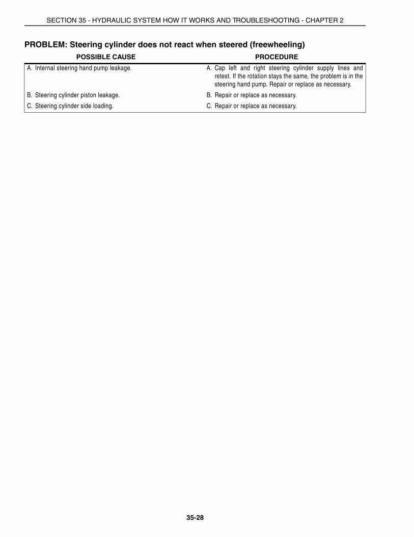
PROBLEM: Steering cylinder does not react when steered (freewheeling)POSSIBLE CAUSE PROCEDURE
A. Internal steering hand pump leakage. A. Cap left and right steering cylinder supply lines andretest. If the rotation stays the same, the problem is in thesteering hand pump. Repair or replace as necessary.
B. Steering cylinder piston leakage. B. Repair or replace as necessary.
C. Steering cylinder side loading. C. Repair or replace as necessary.

SECTION 35 - HYDRAULIC SYSTEM HOW IT WORKS AND TROUBLESHOOTING - CHAPTER 2
35-29
PRIORITY AND REGULATOR VALVE
The Priority/Regulator Valve is located on the top right side of the range transmission. The valve consists of thefollowing components: priority spool, regulator spool, and steering relief valve.
The front section of the dual gear pump and the PFC piston pump supply oil to the Priority/Regulator Valve in thefollowing manner:
Priority Spool (Supplied By PFC Piston Pump)
Oil flows into the Priority/Regulator Valve from the left side port (2). Steering has first priority, oil flows across thepriority spool (11) and out the steering supply port (3). There is a cross drilled passage near the top of the priorityspool. Oil enters this orifice and starts to build pressure against the spring. As steering demand is satisfied,pressure builds on the top of the priority spool (11) and the spool moves down against its spring, opening apassage to the remote and hitch circuits (13).
When the steering circuit is placed on demand this causes a pressure drop on the top end of the priority spool (11).Signal and spring pressure work against pump outlet pressure and the priority spool (11) moves up toaccommodate steering demand.
Once steering demand is satisfied, pressure builds on the top of the priority spool (11) and the spool shifts down toincrease flow to the remote and hitch circuits.
When equipped with trailer brakes, oil is also supplied from the priority valve to the trailer brakes.
Regulator Spool (Supplied By Regulated Pump Section)
Regulated pump flow enters the Priority/Regulator valve at the right side port (7). Oil flows across the regulatorspool (12) and supplies all the regulated circuits through the side port (6) and top port (4). The oil also flowsthrough the orifice near the top of the regulator spool (12). This oil builds pressure and moves the regulator spoolagainst the spring. This regulates pressure and maintains the 335 to 345 psi (23 to 24 bar) in the regulated circuits.These include the transmission control valves, PTO/Diff Lock valve, brake valve and regulated pressure for remotevalve and the hitch valve pilot pressure.
When all regulated circuit demands are met the regulator spool continues to maintain the 335 to 345 psi (23 to 24bar) pressure and allows excess pump flow out the cooler supply port (5).
When a regulated circuit is activated, the regulator spool (12) senses a momentary drop in pressure. The springwill overcome the spool and move it up to allow for an increase in flow of oil to meet the demand. As the demand ismet, pressure again builds on the top side of the spool through the orifice and moves the spool down to maintainregulated pressure.

SECTION 35 - HYDRAULIC SYSTEM HOW IT WORKS AND TROUBLESHOOTING - CHAPTER 2
35-30
Steering Relief Valve
The steering relief valve (9) is located in the Priority/Regulator Valve and is adjustable. The steering relief valve (9)is set to open at 2970 psi (205 bar) +/- 80 psi (5.5 bar).
RD99M135
1. PRIORITY/REGULATOR VALVE2. SUPPLY FROM PFC PISTON PUMP3. SUPPLY TO STEERING4. REGULATED SUPPLY TO SYSTEM5. EXCESS FLOW TO COOLERS
6. REGULATED SUPPLY TO BRAKES7. REGULATED SUPPLY 8. REGULATED PRESSURE ADJUSTMENT9. STEERING RELIEF ADJUSTMENT
10. STEERING SIGNAL TO HAND PUMP
11. PRIORITY SPOOL12. REGULATOR SPOOL13. SUPPLY TO REMOTES
4
5
10
8
9
13
7
2
1 6
SECTION 35 - HYDRAULIC SYSTEM HOW IT WORKS AND TROUBLESHOOTING - CHAPTER 2
35-31
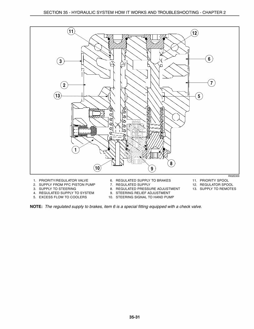
RI02E009
NOTE: The regulated supply to brakes, item 6 is a special fitting equipped with a check valve.
1. PRIORITY/REGULATOR VALVE2. SUPPLY FROM PFC PISTON PUMP3. SUPPLY TO STEERING4. REGULATED SUPPLY TO SYSTEM5. EXCESS FLOW TO COOLERS
6. REGULATED SUPPLY TO BRAKES7. REGULATED SUPPLY 8. REGULATED PRESSURE ADJUSTMENT9. STEERING RELIEF ADJUSTMENT
10. STEERING SIGNAL TO HAND PUMP
11. PRIORITY SPOOL12. REGULATOR SPOOL13. SUPPLY TO REMOTES
810
1
11 12
2
3
7
9
6
13 5
SECTION 35 - HYDRAULIC SYSTEM HOW IT WORKS AND TROUBLESHOOTING - CHAPTER 2
35-32
PFC AXIAL PISTON PUMP
NOTE: The principles of operation for the optional MegaFlow pump are the same as the standard flow pump. Theartwork supporting the PFC pump operation depicts only the standard flow pump.
Principal of Control
All remote valves, the hitch control valve and the trailer brake option each contain a signal port. If a power beyondcircuit has been installed, it also contains a signal port to the pump. Each signal port directs a signal pressure,which is equal to the working pressure in that particular circuit along signal lines through check valves to the pumpcompensator spool. The compensator will place the pump swash plate at the correct angle to meet systemdemands.
A single check valve is located in each signal line connection from the control valves to the compensator spool. Ifseveral control valves are operated at the same time, the signal line at the higher pressure will cause the checkvalve(s) to seat against the signal at the lower pressure. This prevents signal bleed off through other control valvesand ensures that the highest signal line pressure will act on the compensator spool.
Operating Modes
The pump is designed to operate in two different modes according to the demand for flow and pressure placedupon it. These modes are as follows:
Low Pressure Standby
When there is no demand for flow or pressure, the pump provides just enough flow to make up for internal leakagein the hydraulic system at low pressure. In this mode the pump requires very little power to drive it.
Pressure and Flow Delivery and Compensation
When there is a demand for flow and pressure from the hydraulic system, the pump responds to provide only theflow that is required. This limits the power consumption of the system.
SECTION 35 - HYDRAULIC SYSTEM HOW IT WORKS AND TROUBLESHOOTING - CHAPTER 2
35-33
RH02B011
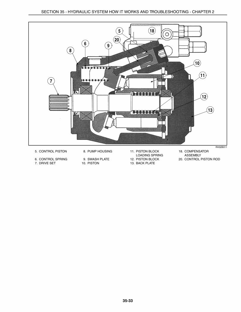
5. CONTROL PISTON 8. PUMP HOUSING 11. PISTON BLOCK LOADING SPRING
18. COMPENSATOR ASSEMBLY
6. CONTROL SPRING 9. SWASH PLATE 12. PISTON BLOCK 20. CONTROL PISTON ROD7. DRIVE SET 10. PISTON 13. BACK PLATE
5
6
7
89
10
11
12
13
18
20
SECTION 35 - HYDRAULIC SYSTEM HOW IT WORKS AND TROUBLESHOOTING - CHAPTER 2
35-34
RH02B010
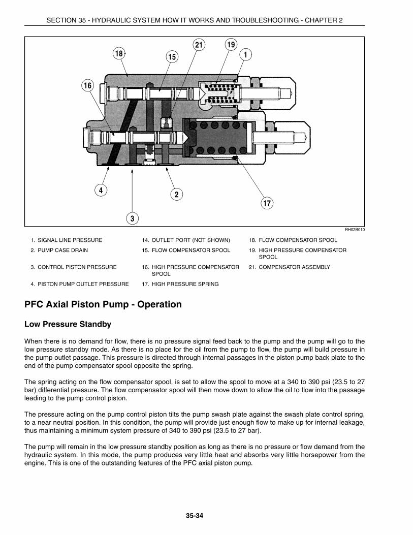
PFC Axial Piston Pump - Operation
Low Pressure Standby
When there is no demand for flow, there is no pressure signal feed back to the pump and the pump will go to thelow pressure standby mode. As there is no place for the oil from the pump to flow, the pump will build pressure inthe pump outlet passage. This pressure is directed through internal passages in the piston pump back plate to theend of the pump compensator spool opposite the spring.
The spring acting on the flow compensator spool, is set to allow the spool to move at a 340 to 390 psi (23.5 to 27bar) differential pressure. The flow compensator spool will then move down to allow the oil to flow into the passageleading to the pump control piston.
The pressure acting on the pump control piston tilts the pump swash plate against the swash plate control spring,to a near neutral position. In this condition, the pump will provide just enough flow to make up for internal leakage,thus maintaining a minimum system pressure of 340 to 390 psi (23.5 to 27 bar).
The pump will remain in the low pressure standby position as long as there is no pressure or flow demand from thehydraulic system. In this mode, the pump produces very little heat and absorbs very little horsepower from theengine. This is one of the outstanding features of the PFC axial piston pump.
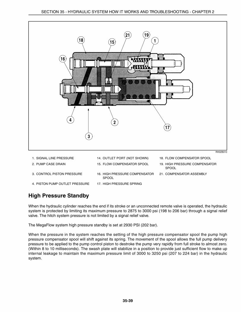
1. SIGNAL LINE PRESSURE 14. OUTLET PORT (NOT SHOWN) 18. FLOW COMPENSATOR SPOOL
2. PUMP CASE DRAIN 15. FLOW COMPENSATOR SPOOL 19. HIGH PRESSURE COMPENSATOR SPOOL
3. CONTROL PISTON PRESSURE 16. HIGH PRESSURE COMPENSATOR SPOOL
21. COMPENSATOR ASSEMBLY
4. PISTON PUMP OUTLET PRESSURE 17. HIGH PRESSURE SPRING
1
4 2
15
16
17
181921
3
SECTION 35 - HYDRAULIC SYSTEM HOW IT WORKS AND TROUBLESHOOTING - CHAPTER 2
35-35
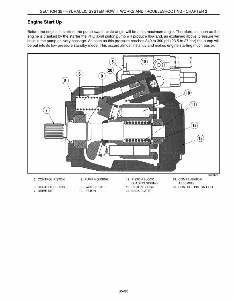
Engine Start Up
Before the engine is started, the pump swash plate angle will be at its maximum angle. Therefore, as soon as theengine is cranked by the starter the PFC axial piston pump will produce flow and, as explained above, pressure willbuild in the pump delivery passage. As soon as this pressure reaches 340 to 390 psi (23.5 to 27 bar) the pump willbe put into its low pressure standby mode. This occurs almost instantly and makes engine starting much easier.
RH02B011
5. CONTROL PISTON 8. PUMP HOUSING 11. PISTON BLOCK LOADING SPRING
18. COMPENSATOR ASSEMBLY
6. CONTROL SPRING 9. SWASH PLATE 12. PISTON BLOCK 20. CONTROL PISTON ROD7. DRIVE SET 10. PISTON 13. BACK PLATE
5
6
7
89
10
11
12
13
18
20

SECTION 35 - HYDRAULIC SYSTEM HOW IT WORKS AND TROUBLESHOOTING - CHAPTER 2
35-36
RH02B010
Pressure and Flow Delivery and Compensation Principle
When oil is required in the system, the flow is controlled by the difference in pressure at opposite ends of thecompensator spool.
When a control valve is operated, pressure at the outlet of the piston pump will drop slightly. This will enable thespring and signal line pressure to shift the flow compensator spool away from the spring end, allowing oil from thecontrol piston to drain past the spool land to tank.
As the oil drains out of the control piston, the swash plate angle will increase and the pump flow will rise until theflow demand has been met. The flow from the pump is determined by the size of the orifice in the control valvewhich is being operated. This orifice is created by limiting the main valve spool travel within the control valve.
When a control valve is operated, the oil pressure in the circuit being supplied will increase to its operatingpressure. This pressure will be transmitted through the sensing line to the spring end of the compensator spool.
Increased Flow Demand
When an additional control valve is operated, it will cause a slight pressure drop at the pump pressure passage.The compensator spool will move up and allow the oil behind the control piston to drain to tank. The swash platewill move and the pump flow will be increased until the extra demand for flow has been met.
1. SIGNAL LINE PRESSURE 14. OUTLET PORT (NOT SHOWN) 18. FLOW COMPENSATOR SPOOL
2. PUMP CASE DRAIN 15. FLOW COMPENSATOR SPOOL 19. HIGH PRESSURE COMPENSATOR SPOOL
3. CONTROL PISTON PRESSURE 16. HIGH PRESSURE COMPENSATOR SPOOL
21. COMPENSATOR ASSEMBLY
4. PISTON PUMP OUTLET PRESSURE 17. HIGH PRESSURE SPRING
1
4 2
15
16
17
181921
3
SECTION 35 - HYDRAULIC SYSTEM HOW IT WORKS AND TROUBLESHOOTING - CHAPTER 2
35-37
Pressure at the pump outlet will increase until it is 340 to 390 psi (23.5 to 27 bar) above the signal line pressure.This increase in pressure will move the pump compensator spool against the spring allowing sufficient flow pastthe spool to the control piston. This will move the swash plate to a position where the increased flow is maintainedand the pressure stabilized.
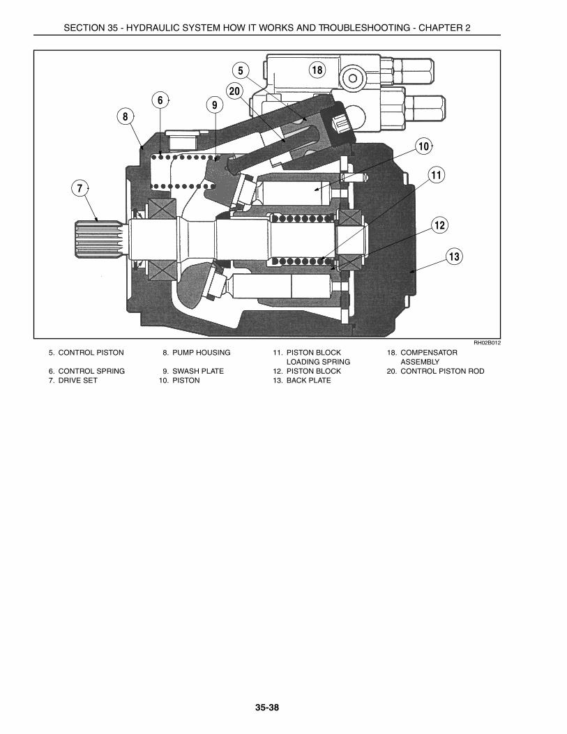
Decreased Flow Demand
If there is a reduction in the demand for flow, pump pressure will increase until the pump outlet pressure exceedsthe signal line pressure by more than 340 to 390 psi (23.5 to 27 bar). This will cause the flow compensator spool tomove down to allow some oil to flow into the pump control piston. This will destroke the pump against the springand thus reduce the pump flow.
When the pump flow has fallen to match the demand, the difference in pressure felt on the opposite ends of thepump compensator spool will return to 340 to 390 psi (23.5 to 27 bar). The pump compensator spool will thenreposition itself to block off the passage to the control piston. This will lock the swash plate at that pumping angle.
SECTION 35 - HYDRAULIC SYSTEM HOW IT WORKS AND TROUBLESHOOTING - CHAPTER 2
35-38
RH02B012
5. CONTROL PISTON 8. PUMP HOUSING 11. PISTON BLOCK LOADING SPRING
18. COMPENSATOR ASSEMBLY
6. CONTROL SPRING 9. SWASH PLATE 12. PISTON BLOCK 20. CONTROL PISTON ROD7. DRIVE SET 10. PISTON 13. BACK PLATE
5
6
7
89
10
11
12
13
18
20
SECTION 35 - HYDRAULIC SYSTEM HOW IT WORKS AND TROUBLESHOOTING - CHAPTER 2
35-39
RH02B010
High Pressure Standby
When the hydraulic cylinder reaches the end if its stroke or an unconnected remote valve is operated, the hydraulicsystem is protected by limiting its maximum pressure to 2875 to 3000 psi (198 to 206 bar) through a signal reliefvalve. The hitch system pressure is not limited by a signal relief valve.
The MegaFlow system high pressure standby is set at 2930 PSI (202 bar).
When the pressure in the system reaches the setting of the high pressure compensator spool the pump highpressure compensator spool will shift against its spring. The movement of the spool allows the full pump deliverypressure to be applied to the pump control piston to destroke the pump very rapidly from full stroke to almost zero.(Within 8 to 10 milliseconds). The swash plate will stabilize in a position to provide just sufficient flow to make upinternal leakage to maintain the maximum pressure limit of 3000 to 3250 psi (207 to 224 bar) in the hydraulicsystem.
1. SIGNAL LINE PRESSURE 14. OUTLET PORT (NOT SHOWN) 18. FLOW COMPENSATOR SPOOL
2. PUMP CASE DRAIN 15. FLOW COMPENSATOR SPOOL 19. HIGH PRESSURE COMPENSATOR SPOOL
3. CONTROL PISTON PRESSURE 16. HIGH PRESSURE COMPENSATOR SPOOL
21. COMPENSATOR ASSEMBLY
4. PISTON PUMP OUTLET PRESSURE 17. HIGH PRESSURE SPRING
1
4
3
2
15
16
17
181921
SECTION 35 - HYDRAULIC SYSTEM HOW IT WORKS AND TROUBLESHOOTING - CHAPTER 2
35-40
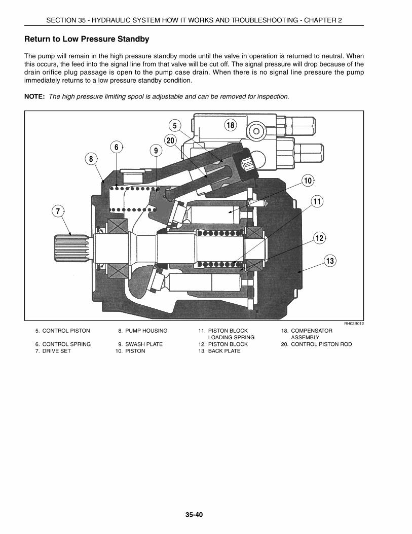
Return to Low Pressure Standby
The pump will remain in the high pressure standby mode until the valve in operation is returned to neutral. Whenthis occurs, the feed into the signal line from that valve will be cut off. The signal pressure will drop because of thedrain orifice plug passage is open to the pump case drain. When there is no signal line pressure the pumpimmediately returns to a low pressure standby condition.
NOTE: The high pressure limiting spool is adjustable and can be removed for inspection.
RH02B012
5. CONTROL PISTON 8. PUMP HOUSING 11. PISTON BLOCK LOADING SPRING
18. COMPENSATOR ASSEMBLY
6. CONTROL SPRING 9. SWASH PLATE 12. PISTON BLOCK 20. CONTROL PISTON ROD7. DRIVE SET 10. PISTON 13. BACK PLATE
5
6
7
89
10
11
12
13
18
20

SECTION 35 - HYDRAULIC SYSTEM HOW IT WORKS AND TROUBLESHOOTING - CHAPTER 2
35-41
RH02B010
1. SIGNAL LINE PRESSURE 14. OUTLET PORT (NOT SHOWN) 18. FLOW COMPENSATOR SPOOL
2. PUMP CASE DRAIN 15. FLOW COMPENSATOR SPOOL 19. HIGH PRESSURE COMPENSATOR SPOOL
3. CONTROL PISTON PRESSURE 16. HIGH PRESSURE COMPENSATOR SPOOL
21. COMPENSATOR ASSEMBLY
4. PISTON PUMP OUTLET PRESSURE 17. HIGH PRESSURE SPRING
1
4
3
2
15
16
17
181921
SECTION 35 - HYDRAULIC SYSTEM HOW IT WORKS AND TROUBLESHOOTING - CHAPTER 2
35-42
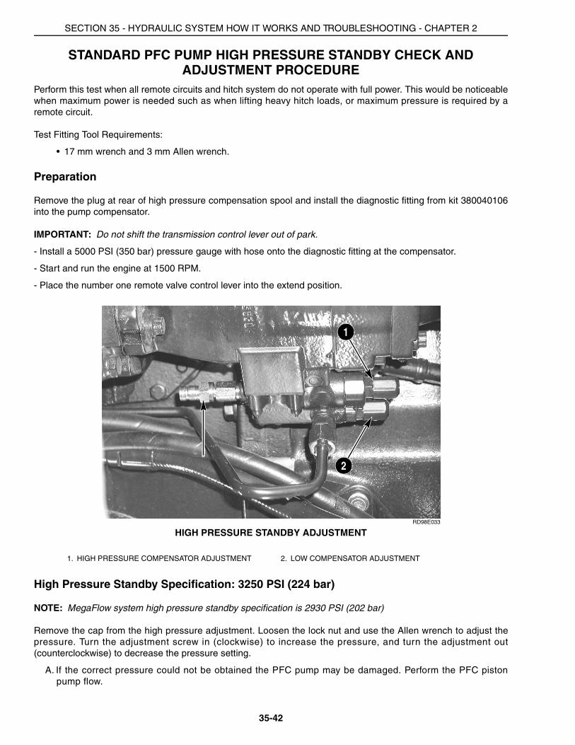
STANDARD PFC PUMP HIGH PRESSURE STANDBY CHECK AND ADJUSTMENT PROCEDURE
Perform this test when all remote circuits and hitch system do not operate with full power. This would be noticeablewhen maximum power is needed such as when lifting heavy hitch loads, or maximum pressure is required by aremote circuit.
Test Fitting Tool Requirements:
• 17 mm wrench and 3 mm Allen wrench.
Preparation
Remove the plug at rear of high pressure compensation spool and install the diagnostic fitting from kit 380040106into the pump compensator.
IMPORTANT: Do not shift the transmission control lever out of park.
- Install a 5000 PSI (350 bar) pressure gauge with hose onto the diagnostic fitting at the compensator.
- Start and run the engine at 1500 RPM.
- Place the number one remote valve control lever into the extend position.
RD98E033
HIGH PRESSURE STANDBY ADJUSTMENT
High Pressure Standby Specification: 3250 PSI (224 bar)
NOTE: MegaFlow system high pressure standby specification is 2930 PSI (202 bar)
Remove the cap from the high pressure adjustment. Loosen the lock nut and use the Allen wrench to adjust thepressure. Turn the adjustment screw in (clockwise) to increase the pressure, and turn the adjustment out(counterclockwise) to decrease the pressure setting.
A. If the correct pressure could not be obtained the PFC pump may be damaged. Perform the PFC pistonpump flow.
1. HIGH PRESSURE COMPENSATOR ADJUSTMENT 2. LOW COMPENSATOR ADJUSTMENT
1
2
SECTION 35 - HYDRAULIC SYSTEM HOW IT WORKS AND TROUBLESHOOTING - CHAPTER 2
35-43
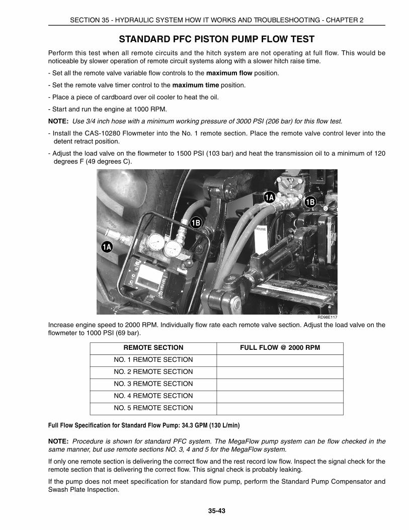
STANDARD PFC PISTON PUMP FLOW TESTPerform this test when all remote circuits and the hitch system are not operating at full flow. This would benoticeable by slower operation of remote circuit systems along with a slower hitch raise time.
- Set all the remote valve variable flow controls to the maximum flow position.
- Set the remote valve timer control to the maximum time position.
- Place a piece of cardboard over oil cooler to heat the oil.
- Start and run the engine at 1000 RPM.
NOTE: Use 3/4 inch hose with a minimum working pressure of 3000 PSI (206 bar) for this flow test.
- Install the CAS-10280 Flowmeter into the No. 1 remote section. Place the remote valve control lever into thedetent retract position.
- Adjust the load valve on the flowmeter to 1500 PSI (103 bar) and heat the transmission oil to a minimum of 120degrees F (49 degrees C).
RD98E117
Increase engine speed to 2000 RPM. Individually flow rate each remote valve section. Adjust the load valve on theflowmeter to 1000 PSI (69 bar).
Full Flow Specification for Standard Flow Pump: 34.3 GPM (130 L/min)
NOTE: Procedure is shown for standard PFC system. The MegaFlow pump system can be flow checked in thesame manner, but use remote sections NO. 3, 4 and 5 for the MegaFlow system.
If only one remote section is delivering the correct flow and the rest record low flow. Inspect the signal check for theremote section that is delivering the correct flow. This signal check is probably leaking.
If the pump does not meet specification for standard flow pump, perform the Standard Pump Compensator andSwash Plate Inspection.
REMOTE SECTION FULL FLOW @ 2000 RPM
NO. 1 REMOTE SECTION
NO. 2 REMOTE SECTION
NO. 3 REMOTE SECTION
NO. 4 REMOTE SECTION
NO. 5 REMOTE SECTION
1A
1A
1B
1B
SECTION 35 - HYDRAULIC SYSTEM HOW IT WORKS AND TROUBLESHOOTING - CHAPTER 2
35-44
STANDARD PFC PISTON PUMP FLOW COMPENSATOR SETTING
Preparation
Test Fitting Tool Requirements:
• 17 mm wrench and 3 mm Allen wrench.
• Two 5000 PSI (350 bar) gauges with hose.
• CAS-10280 Flowmeter.
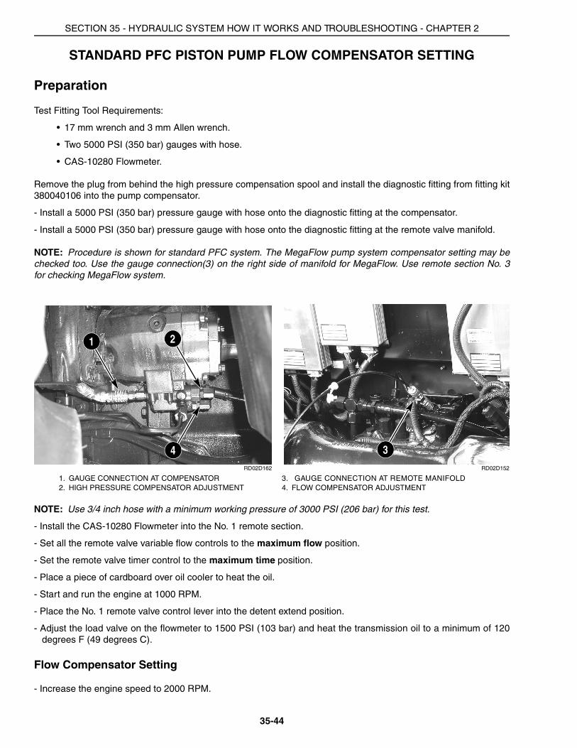
Remove the plug from behind the high pressure compensation spool and install the diagnostic fitting from fitting kit380040106 into the pump compensator.
- Install a 5000 PSI (350 bar) pressure gauge with hose onto the diagnostic fitting at the compensator.
- Install a 5000 PSI (350 bar) pressure gauge with hose onto the diagnostic fitting at the remote valve manifold.
NOTE: Procedure is shown for standard PFC system. The MegaFlow pump system compensator setting may bechecked too. Use the gauge connection(3) on the right side of manifold for MegaFlow. Use remote section No. 3for checking MegaFlow system.
RD02D162 RD02D152
NOTE: Use 3/4 inch hose with a minimum working pressure of 3000 PSI (206 bar) for this test.
- Install the CAS-10280 Flowmeter into the No. 1 remote section.
- Set all the remote valve variable flow controls to the maximum flow position.
- Set the remote valve timer control to the maximum time position.
- Place a piece of cardboard over oil cooler to heat the oil.
- Start and run the engine at 1000 RPM.
- Place the No. 1 remote valve control lever into the detent extend position.
- Adjust the load valve on the flowmeter to 1500 PSI (103 bar) and heat the transmission oil to a minimum of 120degrees F (49 degrees C).
Flow Compensator Setting
- Increase the engine speed to 2000 RPM.
1. GAUGE CONNECTION AT COMPENSATOR 3. GAUGE CONNECTION AT REMOTE MANIFOLD2. HIGH PRESSURE COMPENSATOR ADJUSTMENT 4. FLOW COMPENSATOR ADJUSTMENT
1
3
2
4
SECTION 35 - HYDRAULIC SYSTEM HOW IT WORKS AND TROUBLESHOOTING - CHAPTER 2
35-45
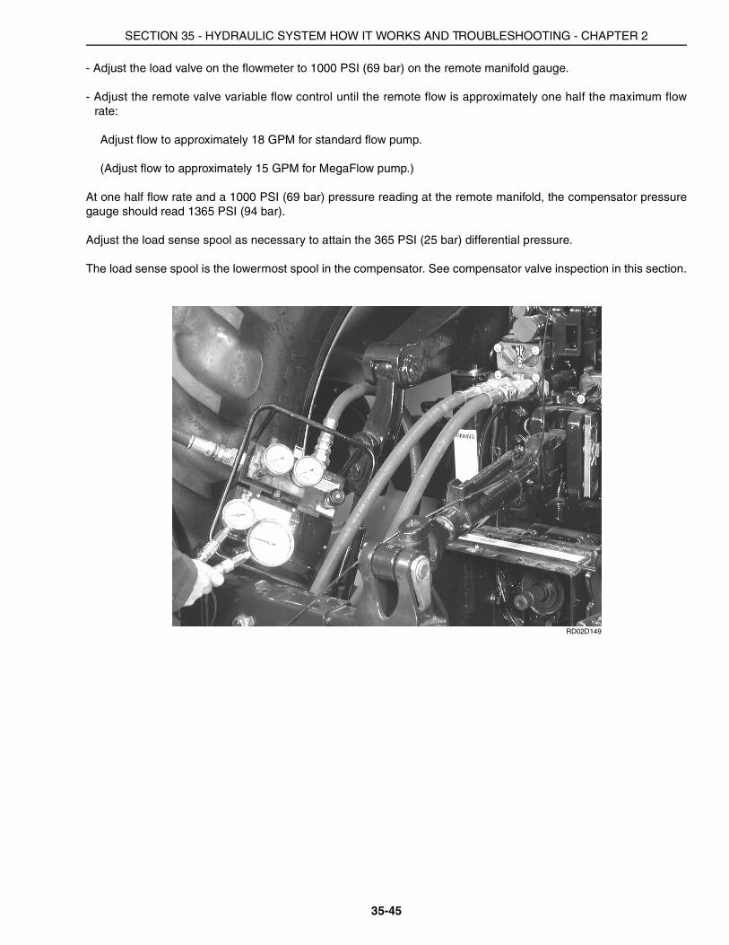
- Adjust the load valve on the flowmeter to 1000 PSI (69 bar) on the remote manifold gauge.
- Adjust the remote valve variable flow control until the remote flow is approximately one half the maximum flowrate:
Adjust flow to approximately 18 GPM for standard flow pump.
(Adjust flow to approximately 15 GPM for MegaFlow pump.)
At one half flow rate and a 1000 PSI (69 bar) pressure reading at the remote manifold, the compensator pressuregauge should read 1365 PSI (94 bar).
Adjust the load sense spool as necessary to attain the 365 PSI (25 bar) differential pressure.
The load sense spool is the lowermost spool in the compensator. See compensator valve inspection in this section.
RD02D149

SECTION 35 - HYDRAULIC SYSTEM HOW IT WORKS AND TROUBLESHOOTING - CHAPTER 2
35-46
STANDARD PUMP COMPENSATOR VALVE INSPECTIONPerform this inspection only after completing the high pressure standby check and the piston pump flow test.
RH98D014
Test Fitting and Tool Requirements:
• 17 mm wrench
• 3 mm Allen wrench
• 5 mm Allen wrench
Test Procedure:
- With two wrenches, disconnect the signal line tube at the PFC pump compensator.
- Remove the compensator valve from the PFC pump.
- Remove high pressure cap. Measure and record the distance from the lock nut to the end of the high pressureadjustment screw.
____________
- Remove low pressure cap. Measure and record the distance from the lock nut to the end of the low pressureadjustment screw.
____________
- Check for broken springs
- Remove high pressure spool. Make sure it moves freely within the bore.
- Remove low pressure spool. Make sure it moves freely within the bore.
- Clean cored passages in the compensator valve.
- Assemble compensator valve. Set high and low pressure adjustment screws to their original positions.
- Reinstall compensator. Perform PFC Piston Pump Flow Test.
- If the pump is still not able to meet specifications remove PFC pump for repair or replacement. See Section 35Chapter 8.
1. HIGH PRESSURE SPOOL 4. LOW PRESSURE SPOOL2. HIGH PRESSURE ADJUSTMENT SCREW 5. CAP3. LOW PRESSURE ADJUSTMENT SCREW 6. LOCK NUT
2
45
1
3
6

SECTION 35 - HYDRAULIC SYSTEM HOW IT WORKS AND TROUBLESHOOTING - CHAPTER 2
35-47
PFC PUMP OPERATIONAL PROBLEMS
POOR OVERALL HYDRAULIC PERFORMANCE - LOW FLOW TO HITCH AND ALL REMOTE VALVECIRCUITS
A. Low hydraulic oil level in transmission.
B. Low charge/lube pressure. Perform rear charge/lube pump pressure test in this section. Complete theentire test procedure
C. Perform the PFC pump high pressure standby test.
D. Perform the PFC piston pump flow test.
E. After completing items A,B,C and D from above:
- If the pump performance is now okay troubleshooting is completed.
- If poor overall hydraulic performance continues, remove PFC pump for repair or replacement. See Section35 Chapter 8.
POOR HYDRAULIC PERFORMANCE - LOW FLOW TO HITCH AND ALL BUT ONE REMOTE VALVE CIRCUIT
A. Bad signal check in the one working remote section.
POOR HYDRAULIC PERFORMANCE - HITCH OPERATING OKAY, BUT LOW FLOW FROM ALL REMOTECIRCUITS
A. Go to Section 55 Chapter 6and check for remote system fault codes
- If there are fault codes continue with fault code troubleshooting.
- If there no fault codes check hitch valve signal check for leakage.
POOR HYDRAULIC PERFORMANCE - LOW FLOW OR ERRATIC HITCH OPERATION, BUT ALL REMOTEVALVE CIRCUITS ARE OPERATING OKAY
A. Go to Section 55Chapter 3 and check for hitch system fault codes
- If there are fault codes continue with fault code troubleshooting.
- If there no fault codes go to Section 35Chapter 9.
PFC SYSTEM REMAINS ON HIGH PRESSURE STANDBY, OR IS SLOW TO COME OFF HIGH PRESSURESTANDBY
A. Pump compensator bleed down orifice is blocked, or partially blocked.
SECTION 35 - HYDRAULIC SYSTEM HOW IT WORKS AND TROUBLESHOOTING - CHAPTER 2
35-48