5th wheel hitch ·
TRANSCRIPT

US Pat. 7,506,886US Pat. 7,753,392CA Pat. 2,576,427AS Pat. 2007200421
HJ26077, Rev 1701/20
5tH wHeel HitcH6077 18K Autoslide & 6107 21K Autoslide

Page 2 HJ26077
VERY IMPORTANT – PLEASE READ CAREFULLY
The Demco 5th wheel Autoslide hitch comes assembled from the factory to help make the installation easier and quicker. The only prep work necessary is to bolt on the side plates. There are two different mounting systems for the Autoslide hitch. It can be mounted on either the Premier/UL base rails or the UMS (Underbed Mounting System) base rails. Once the mounting system has been determined there is a side rail kit available for either.
For the Premier/UL mounting system the 6003 adaptor side plate kit (shown below) will be used and for the UMS mount-ing system the 6004 adaptor side plate kit will be used. Instructions to install both types are included in the carton with the adaptor plates as well as with these instructions.
Also included with these instructions is a procedure for adjusting the king pin capture plates. This is the most critical procedure that needs to be done in order to ensure the proper and safe use of the hitch. Please read and follow the in-structions on how to adjust them VERY CAREFULLY. These instructions also include the procedure for replacing the slide disc(s) if necessary (shown below). The Autoslide 5th wheel hitch comes with a limited five year warranty that covers most parts and labor. The slide disc is warranted for a period of one year as it is considered a consumable part.
CRITICALLY IMPORTANT
Capture plates must be adjusted to the width of the trailer pin box in order for the automatic slide mechanism to oper-ate and function properly. Failure to do so can result in improper alignment and may cause damage to the hitch and/or trailer. It is best to measure the pin box width first and adjust the plates evenly on either side to 1/8” over the total width of the pin box. This adjustment is made only once at time of initial hookup, or if a trailer with a different width pin box is towed.
The Autoslide automatic sliding hitch is designed for short box trucks to give additional clearance between the truck’s cab and the trailer during turning maneuvers. This hitch may allow 90° turns, but NOT IN EVERY CASE.
There are many variables that can influence the ability to make a full 90° turn, such as trailer width, sharp or rounded trailer corners, truck cab profile. The placement of the trailer king pin box also has a part in determining the turning abil-ity of the truck and trailer. It is always recommended, even with an automatic sliding hitch, that the trailer be equipped with an extended pin box that projects out forward from the trailer.
Caution should always be exercised when using this or any hitch to ensure that the driver is aware of clearance between the truck and trailer when executing turning maneuvers.
VERY IMPORTANT – PLEASE READ CAREFULLY
The 5th wheel Autoslide hitch was designed for use with recreational style 5th wheel trailers with a 2” king pin only. It is not designed or intended for commercial, industrial, or agricultural type towing applications or similar type applications (i.e.- car trailer, flat bed, horse, etc.).
This hitch is designed for use with short box trucks. There is no expressed or implied guarantee that a full turn can or will be achieved with the Autoslide hitch.
It is designed to work with standard trailer pin boxes between 12” minimum to 14” maximum width. Optional adapter plates are required for most suspension pin boxes.
Any use of the Autoslide hitch, other than its intended use, may void any manufacturer’s warranty(s), ex-pressed or otherwise.
Please consult vehicle owner’s manual for 5th wheel towing instructions.
iNtRODUctiONwARRANtY POlicY, OPeRAtOR MANUAlS, PARtS MANUAlS & ReGiStRAtiON
Go online to www.demco-products.com to review Demco warranty policies, operator manuals and register your Demco product.

HJ26077 Page 3
Torque figures indicated are valid for non-greased or non-oiled threads and heads unless otherwise specified. Therefore, do not grease or oil bolts or capscrews unless otherwise specified in this manual. When using locking elements, increase torque values by 5%.
* GRADE or CLASS value for bolts and capscrews are identified by their head markings.
Torque Specifications
BOLT TORQUE DATA FOR STANDARD NUTS, BOLTS, AND CAP-SCREWS.
Tighten all bolts to torques specified in chart unless otherwise noted. Check tightness of bolts periodically, using bolt chart as guide. Replace hardware with same grade bolt.
NOTE: Unless otherwise specified, high-strength Grade 5 hex bolts are used throughout assembly of equipment.
Bolt Torque for Standard bolts * GRADE 2 GRADE 5 GRADE 8 “A” lb-ft (N.m) lb-ft (N.m) lb-ft (N.m)
1/4” 6 (8) 9 (12) 12 (16)5/16” 10 (13) 18 (25) 25 (35)3/8” 20 (27) 30 (40) 45 (60)7/16” 30 (40) 50 (70) 80 (110)1/2” 45 (60) 75 (100) 115 (155)9/16” 70 (95) 115 (155) 165 (220)5/8” 95 (130) 150 (200) 225 (300)3/4” 165 (225) 290 (390) 400 (540)7/8” 170 (230) 420 (570) 650 (880)1” 225 (300) 630 (850) 970 (1310)
Bolt Torque for Metric bolts *
CLASS 8.8 CLASS 9.8 CLASS 10.9 “A” lb-ft (N.m) lb-ft (N.m) lb-ft (N.m) 6 9 (13) 10 (14) 13 (17) 7 15 (21) 18 (24) 21 (29) 8 23 (31) 25 (34) 31 (42) 10 45 (61) 50 (68) 61 (83) 12 78 (106) 88 (118) 106 (144) 14 125 (169) 140 (189) 170 (230) 16 194 (263) 216 (293) 263 (357) 18 268 (363) -- -- 364 (493) 20 378 (513) -- -- 515 (689) 22 516 (699) -- -- 702 (952) 24 654 (886) -- -- 890 (1206)
BOlt tORQUe

Page 4 HJ26077
Measure the width of the pinbox.1. Adjust the capture plates so they are 1/8” wider than the pinbox. Example: if pin box measures 12” the capture plates 2. should measure 12-1/8”. Use center pin to measure from so the capture plates are centered on the head. Final ad-justment may be needed.Finger tighten the two inside jam nuts against the capture plate mount.3. Tightening outside jam nuts against thick mounting plate.4.
5th wheel Autoslide Gear Adjustment Bolt
The gear adjustment bolt is preset at the factory and is not to be adjusted at the time of installation. It only needs to be adjusted if there is too much for and aft movement in the slide assembly when stopping and starting in the straight tow-ing position. There may be some movement experienced when in a turn but there should be very little when the truck and trailer are in parallel alignment.
To adjust bolt:
Make sure the hitch position is parallel with the truck box and not in a turned position. It should be forward towards 1. the cab of the truck. Using a 1 1/8” wrench, loosen the nut that is tight against the rear end plate.2. Turn the bolt in clockwise until it stops against the gear. 3. Back the bolt off 1/8 of a turn and retighten the jam nut to lock into position.4.
Tighten jam nuts against plate
Finger tighten jam nuts
iNStAllAtiON

HJ26077 Page 5
Because the Autoslide hitch uses capture plates to maintain the hitch head position in relation to the trailer king pin, the trailer can only be coupled and uncoupled when it is in straight or slightly angled alignment. The Autoslide can couple and uncouple up to a 10-15° trailer angle quite easily. Anything over this degree of angle will not allow for proper cou-pling.
YES YES NO
Autoslide Inspection and Care
The Autoslide hitch should be inspected before each trip to insure safe operation and travel. Remove the two side gear covers and inspect the gear system for any excessive wear on gear or transition bearing or guide. Light grease may be used on the gear area. Reinstall plastic covers.
coupling Procedure
OPeRAtiON

Page 6 HJ26077
DO NOT install hitch handle in a position that the pin box could come in contact with or interfere with the latch of the hitch handle when turning! If the pin box contacts the hitch handle or its latch when turning, the trailer may become unhitched.
WARNING
The Autoslide hitch has an outrigger or bar that is designed to help carry and distribute the hitch and trailer weight when the hitch is near its full travel distance. This outrigger needs to be adjusted after the hitch has been installed at its correct height within the truck bed. The outrigger bar and bolts need to be loosely fitted to the end plate of the hitch that is closest to the tailgate of the truck before the installation procedure. If the hitch is to be mounted in the lowest setting with the UMS mounting base rail system, install the outrigger as shown in the very bot-tom drawing (2), using only 1 nut on the top of the bent flange to secure the outrigger. On all other height settings, install the outrigger as shown in the top drawing (1), using 2 nuts to adjust and lock the bar.
Once the hitch is installed and locked into place in the truck bed, adjust the height of the outrigger bar so that it is snug up against the top of the truck bed and tighten both nuts to lock into place.
5th wheel Double Pivot Head Assembly
The dampener stops the hitch head from flopping back and forth in the truck when the trailer is not hooked up. The ure-thane compresses under load so it does not restrict the fore and aft movement when coupled.
Before attaching the hitch head to the saddle assembly the urethane dampener will need to be installed. It is included in the bag with the bolt and nut for the hitch handle. Simply press into hole that is punched into the bottom side of the hitch as shown below.
Note (Read carefully before installing): Handle can be posi-tioned toward the front or the back if it is found to interfere with the trailer in any way. Verify this before traveling.
Slide yellow gripped handle over locking bar, the handle 1. may point forward, upward or backward. **DO NOT have pointing upward if it is found to interfere with the trailer in any way during turning.Fasten with 3/8” x 1 ¾” bolt and lock nut provided.2.
Handle Assembly Instructions
iNStAllAtiONOUtRiGGeR ADJUStMeNt
HJ26077 Page 7
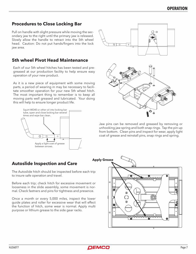
Each of our 5th wheel hitches has been tested and pre-greased at our production facility to help ensure easy operation of your new product.
As it is a new piece of equipment with some moving parts, a period of wearing in may be necessary to facili-tate smoother operation for your new 5th wheel hitch. The most important thing to remember is to keep all moving parts well greased and lubricated. Your doing this will help to ensure longer product life.
Jaw pins can be removed and greased by removing or unhooking jaw spring and both snap rings. Tap the pin up from bottom. Clean pins and inspect for wear, apply light coat of grease and reinstall pins, snap rings and spring.
5th wheel Pivot Head Maintenance
Procedures to Close Locking Bar
Pull on handle with slight pressure while moving the sec-ondary jaw to the right until the primary jaw is released. Slowly allow the handle to retract into the 5th wheel head. Caution: Do not put hands/fingers into the lock jaw area.
Squirt WD40 or other oil into locking bar tube, open and close locking bar several times and wipe bar clean.
Apply a light coat of grease between arrows.
Autoslide Inspection and Care
The Autoslide hitch should be inspected before each trip to insure safe operation and travel.
Before each trip; check hitch for excessive movement or looseness in the slide assembly, some movement is nor-mal. Check fastners and pins for tightness and presence.
Once a month or every 5,000 miles, inspect the lower guide plates and roller for excessive wear that will effect the function of hitch, some wear is normal. Apply multi purpose or lithium grease to the side gear racks.
Apply Grease
OPeRAtiON

Page 8 HJ26077
Place wheel chocks on both sides of trailer 1. wheels.Lower trailer jacks to ground and extend un-2. til load is level with truck suspension. If on soft ground, place support under jack feet to pre-vent trailer from settling.Lower tailgate on truck.3. Disconnect power cable and break away switch.4. Remove lock pin and pull handle out. If handle 5. will not stay out, install safety pin in second han-dle hole just outside of frame handle bushing.Drive truck slowly away from trailer.6.
Inspect all fasteners for tightness at least every 1. 2,000 miles of operation.Inspect jaw and jaw bar for freedom of move-2. ment and proper operation before each use. Replace all damaged or worn parts.Keep all moving parts of hitch well lubricated.3. It is recommended to use grease or a 3/16” 4. maximum Teflon disc to help prevent wear on top plate surface.
Coupling Procedure Uncoupling Procedure
Very ImportantMaintenance Instructions
Very Important WarningsKnow your vehicle and trailer GVWR and CVWR. 1. DO NOT exceed capacity of hitch.Hitch is for use with only a standard 2” king pin.2.
Safety pin MUST be fastened securely before moving vehicle and/or traveling
Ready to Couple Coupled and Locked Uncoupled
VISUALLY INSPECT JAW LOCKING MECHANISM BEFORE TRAVELING
Remove safety lock pin if installed andpull handle untiljaw locks open.
With handle in "Ready to Couple" position, back-up tow vehicle to couple trailer and hitch. Insert safety pin thru tab and hole in handle.
NOTE: Ensure safety lock pin is inserted properly. Apply trailer brakes before jacks are raised and
wheel chocks are removed.
Place wheel chock on each side of trailer wheels.1. Adjust trailer jacks until trailer is a height for hook up. 2. King pin plate should contact hitch approximately 1/2” below level. Lower tailgate of truck.3. If hitch is in locked position, remove safety pin and pull 4. handle out to the “Ready to Couple” position.Line truck so that the hitch will accept king pin. Back 5. truck up slowly towards trailer until king pin engages. Hitch will lock when king pin is fully engaged.With the trailer coupled, visually check to see if hitch is 6. completely locked by looking at the handle position, as well as visually checking to ensure that the jaw bar has traveled completely across the front of the king pin.Place safety pin thru the tab and the hole in the handle. 7. This will prevent handle from opening.Connect power cable and breakaway switch cable be-8. tween truck and trailer.Close and latch tailgate.9. Apply trailer brakes and try to pull forward slowly to 10. double check that hitch is locked. Trailer should pre-vent truck from moving.Completely raise trailer jacks. Check for proper clear-11. ance between truck box and trailer.Pick up and store wheel chocks. You are now ready to 12. travel.
To uncouple, remove saftey pin, pull handle straight out until the
jaw locks open. If jaw will not stay open, install safety pin in
second handle hole just outside of frame handle bushing.
5th wheel Hitch Operation instructions
OPeRAtiON

HJ26077 Page 9
6081 Parts Breakdown
Patent Pending
ITEM PART # DESCRIPTION QTY
1 00908 BOLT, .375 NC X 1.75 HEX GR.5 1
2 02592 NUT, .375NC NYLON LOCK 1
3 03547 BOLT .313NC X 2.25 GR5 HEX 1
4 03701 NUT, .75 JAM 8
5 03787 SCREW #10NC X .50 SELF DRILLING 1
6 05337 SAFETY LOCK PIN ASSEMBLY 1
7 14315 SPRING, TENSION 1
8 14385 SPRING COMPRESS .105 MW 1
9 14594-95 JAW HOOK 1
10 14595-95 SECONDARY LATCH JAW 1
11 14735-95 MAIN JAW PIN 1
12 14736-95 SECONDARY JAW PIN 1
13 14737-95 BAR/JAW LINK 1
14 14741-76 5th WHEEL DOUBLE PIVOT HEAD 1
15 14743-95 CAPTURE PLATE ASSEMBLY 2
16 14747 SCREW, .313NC X .25 SOCKET HD CAP 2
Please order replacement parts by PART NO. and DESCRIPTION
ITEM PART # DESCRIPTION QTY
17 14749 SNAP RING EXT FOR .50 SHAFT 1
18 14750 SNAP RING EXT F/ .75 SHAFT 1
19 14865 ROLL PIN, .25 X 1.00 2
20 15769 URETHANE BUMPER 1
21 15894 CAPTURE PLATE MOUNT 2
22 15934 HANDLE ASSEMBLY 1
23 16338 BOLT, .438NC X 1.00 SERR FLG HEX GR.5 8
24 6094 LOCKING BAR ASSEMBLY 1
Please order replacement parts by PART NO. and DESCRIPTION
US Pat. 9,550,398
6081 Pivot Head Parts BreakdownPARtS BReAKDOwN

Page 10 HJ26077
US Pat. 7,506,886US Pat. 7,753,392CA Pat. 2,576,427AS Pat. 2007200421
PARtS BReAKDOwN6077 PARtS BReAKDOwN
iteM PARt # DeScRiPtiON QtY.1 00085 .50 FLAT WASHER 2
2 00253 .75 NC HEX NUT 1
3 00967 BOLT, .50NC X 1.25 2
4 01254 BOLT, .50 NC X 1.50 GR.5 HEX 5
5 01896 BOLT, .50 NC X 4.00 HEX HEAD GR.5 4
6 02178 NUT, .50NC LOCK, NY. INSERT 12
7 02961 .75NC NYLON INSERT LOCK NUT 1
8 04073 BOLT .50NC X 3.00 GR5 HEX 2
9 05047 BOLT, .75NC X 2.50 GR 5 HEX 1
10 05366 BOLT, .625 NC X 1.25 HEX HEAD GR.5 1
11 07908-95 HEAVY WASHER 1
12 11099 BOLT, .75 NC X 5.00 HEX HEAD GR. 8 1
13 11337-95 HINGE BUSHING 1
14 11779 SCREW, .25NC X .75 FLAT HD PHIL 4
15 13317 CLEVIS SPACER WASHER 1
16 14221 LYNCH PIN, .313 1
17 14222-95 AS PIVOT PIN 1” X 9.38 1
18 14319 BEARING, AS UPPER 1
19 14488 .50 FLAT WASHER NARROW RIM 8
20 14706-76 5TH WHEEL AS MAIN FRAME 1
21 14707-76 GUIDE TUBE 2
22 14708-76 GUIDE TUBE SUPPORT 2
23 14709-76 AS UPPER SLIDE ASSEMBLY 1
Please order replacement parts by PART NO. and DESCRIPTION
iteM PARt # DeScRiPtiON QtY.
24 14710-76 AS MAIN GEAR ASSEMBLY 1
25 14711 AS WEAR PLATE 2
26 14712 AS GEAR RACK 2
27 14714-95 BEARING SPACER/SLEEVE 1
28 14716 RACK COVER 2
29 14717 CAP PLUG SQUARE 2 X 18 GA 4
30 14920-76 AS GUIDE ASSEMBLY 1
31 14985-95 ROLLER 1
32 15159-95 SPACER BUSHING 2
33 15769 URETHANE PIVOT BUMPER 3/8” THICK 2
34 15778 5th WHEEL HEAD YOKE 1
35 16235 BUSHING IGUS 25MM ID X 28MM OD 1
36 16845 RIVET .25 x .625 LARGE DOME HD 4
37 6018 OUTRIGGER BAR ASSEMBLY 1
Please order replacement parts by PART NO. and DESCRIPTION

HJ26077 Page 11
US Pat. 7,506,886US Pat. 7,753,392CA Pat. 2,576,427AS Pat. 2007200421
PARtS BReAKDOwN6107 PARtS BReAKDOwN
iteM PARt # DeScRiPtiON QtY.1 00085 .50 FLAT WASHER 2
2 00253 .75 NC HEX NUT 1
3 00967 BOLT, .50NC X 1.25 2
4 01254 BOLT, .50 NC X 1.50 GR.5 HEX 5
5 01896 BOLT, .50 NC X 4.00 HEX HEAD GR.5 4
6 02178 NUT, .50NC LOCK, NY. INSERT 12
7 02961 .75NC NYLON INSERT LOCK NUT 1
8 04073 BOLT .50NC X 3.00 GR5 HEX 2
9 05047 BOLT, .75NC X 2.50 GR 5 HEX 1
10 05366 BOLT .625NC X 1.25 GR5 HEX 1
11 07908-95 HEAVY WASHER 1
12 11099 BOLT, .75 NC X 5.00 HEX HEAD GR. 8 1
13 11337-95 HINGE BUSHING 1
14 11779 SCREW, .25NC X .75 FLAT HD PHIL 4
15 13317 CLEVIS SPACER WASHER 1
16 14221 LYNCH PIN, .313 1
17 14222-95 AS PIVOT PIN 1” X 9.38 1
18 14319 BEARING, AS UPPER 1
19 14488 .50 FLAT WASHER NARROW RIM 8
20 14707-76 GUIDE TUBE 2
21 14708-76 GUIDE TUBE SUPPORT 2
22 14709-76 AS UPPER SLIDE ASSEMBLY 1
23 14711 AS WEAR PLATE 2
24 14712 AS GEAR RACK 2
25 14714-95 BEARING SPACER/SLEEVE 1
26 14717 CAP PLUG SQUARE 2 X 18 GA 4
Please order replacement parts by PART NO. and DESCRIPTION
iteM PARt # DeScRiPtiON QtY.
27 14938-76 21K AS GUIDE ASSEMBLY 1
28 14982-76 AS MAIN GEAR ASSEMBLY 1
29 14983-76 5TH WHEEL AS MAIN FRAME 1
30 14984 RACK COVER 2
31 14985-95 ROLLER 1
32 15159-95 SPACER BUSHING 2
33 15542-76 RACK SPACER 2
34 15769 URETHANE PIVOT BUMPER 3/8” THICK 2
35 15778 5th WHEEL HEAD YOKE 1
36 16235 BUSHING IGUS 25MM ID X 28MM OD 1
37 16845 RIVET .25 x .625 LARGE DOME HD 4
38 6018 OUTRIGGER BAR ASSEMBLY 1
Please order replacement parts by PART NO. and DESCRIPTION
