scte 137-7 2010.pdf
TRANSCRIPT

7/26/2019 SCTE 137-7 2010.pdf
http://slidepdf.com/reader/full/scte-137-7-2010pdf 1/36
ENGINEERING COMMITTEE
Data Standards Subcommittee
SCTE 137-7 2010
Modular Headend Architecture Part 7:
EQAM Architectural Overview Technical Report

7/26/2019 SCTE 137-7 2010.pdf
http://slidepdf.com/reader/full/scte-137-7-2010pdf 2/36
ii
NOTICE
The Society of Cable Telecommunications Engineers (SCTE) Standards are intended to serve the public interest by providing specifications, test methods and procedures that promote uniformity
of product, interchangeability and ultimately the long term reliability of broadbandcommunications facilities. These documents shall not in any way preclude any member or non-member of SCTE from manufacturing or selling products not conforming to such documents, norshall the existence of such standards preclude their voluntary use by those other than SCTEmembers, whether used domestically or internationally.
SCTE assumes no obligations or liability whatsoever to any party who may adopt the Standards.Such adopting party assumes all risks associated with adoption of these Standards, and acceptsfull responsibility for any damage and/or claims arising from the adoption of such Standards.
Attention is called to the possibility that implementation of this standard may require the use of
subject matter covered by patent rights. By publication of this standard, no position is taken withrespect to the existence or validity of any patent rights in connection therewith. SCTE shall not be responsible for identifying patents for which a license may be required or for conductinginquiries into the legal validity or scope of those patents that are brought to its attention.
Patent holders who believe that they hold patents which are essential to the implementation ofthis standard have been requested to provide information about those patents and any relatedlicensing terms and conditions. Any such declarations made before or after publication of thisdocument are available on the SCTE web site at http://www.scte.org.
All Rights Reserved
© Society of Cable Telecommunications Engineers, Inc. 2010140 Philips RoadExton, PA 19341
Note: DOCSIS® is a registered trademark of Cable Television Laboratories, Inc., and is used in this documentwith permission.

7/26/2019 SCTE 137-7 2010.pdf
http://slidepdf.com/reader/full/scte-137-7-2010pdf 3/36
iii
Contents
1 SCOPE .................................................................................................................................................................. 1
1.1 I NTRODUCTION AND PURPOSE ........................................................................................................................ 1 1.2 R EQUIREMENTS AND CONVENTIONS .............................................................................................................. 1
2 REFERENCES .................................................................................................................................................... 2
2.1 I NFORMATIVE R EFERENCES ............................................................................................................................ 2 2.2 R EFERENCE ACQUISITION ............................................................................................................................... 3
3 TERMS AND DEFINITIONS ............................................................................................................................ 4
4 ABBREVIATIONS AND ACRONYMS ............................................................................................................ 5
5 REFERENCE ARCHITECTURE ..................................................................................................................... 7
5.1 VIDEO HEADEND R EFERENCE ARCHITECTURE ............................................................................................... 7 5.1.1 Video EQAM Interfaces ......................................................................................................................... 9
5.2 M-CMTS R EFERENCE ARCHITECTURE ........................................................................................................ 10
6 ARCHITECTURAL ENTITIES ...................................................................................................................... 12
6.1 EDGE R ESOURCE MANAGER ......................................................................................................................... 12 6.2 EQAM ......................................................................................................................................................... 12 6.3 M-CMTS CORE ............................................................................................................................................ 13 6.4 DOCSIS TIMING SERVER ............................................................................................................................. 13 6.5 NMS/OSS .................................................................................................................................................... 13
7 BASIC EQAM OPERATION ........................................................................................................................... 14
7.1 PROFILES ...................................................................................................................................................... 14 7.2 I NTERFACES .................................................................................................................................................. 14
7.2.1 ERMI .......... .......... ........... .......... ........... .......... ........... .......... ........... .......... ........... ........... ........... .......... . 14 7.2.2 EQAM-VSI .......... ........... .......... ........... .......... ........... .......... ........... .......... ........... .......... ........... .......... ... 15
7.2.3 EQAM-PMI .......... ........... .......... ........... ........... .......... ........... .......... ........... .......... ........... ........... .......... . 15 7.2.4 DRFI .......... ........... .......... ........... .......... ........... .......... ........... .......... ........... .......... ........... ........... .......... . 16 7.2.5 DEPI .......... ........... .......... ........... .......... ........... .......... ........... .......... ........... .......... ........... ........... .......... . 17 7.2.6 DTI .......... .......... ........... .......... ........... .......... ........... .......... ........... ........... .......... ........... .......... ........... .... 18 7.2.7 ERMI .......... .......... ........... .......... ........... .......... ........... .......... ........... .......... ........... ........... ........... .......... . 19
8 MODULAR CMTS INTERFACE AND VIDEO EQAM DOCUMENTS .................................................... 20
8.1 MODULAR CMTS I NTERFACE DOCUMENTS ................................................................................................. 20 8.1.1 DRFI .......... ........... .......... ........... .......... ........... .......... ........... .......... ........... .......... ........... ........... .......... . 20 8.1.2 DEPI .......... ........... .......... ........... .......... ........... .......... ........... .......... ........... .......... ........... ........... .......... . 20 8.1.3 DTI .......... .......... ........... .......... ........... .......... ........... .......... ........... ........... .......... ........... .......... ........... .... 20 8.1.4 ERMI .......... .......... ........... .......... ........... .......... ........... .......... ........... .......... ........... ........... ........... .......... . 21 8.1.5 M-OSSI ................. .......... ........... .......... ........... .......... ........... .......... ........... ........... .......... ........... .......... . 21
8.2 VIDEO EQAM I NTERFACE DOCUMENTS....................................................................................................... 22 8.2.1 ERMI Specification .......... ........... .......... ........... ........... .......... ........... ........... .......... ........... .......... .......... 22 8.2.2 EQAM VSI Specification ........... .......... ........... ........... .......... ........... ........... .......... ........... .......... ........... . 22 8.2.3 EQAM PMI Specification ............ ........... .......... ........... ........... .......... ........... ........... .......... ........... ........ 22
8.3 SUMMARY OF SPECIFICATION APPLICABILITY .............................................................................................. 22
APPENDIX I DIGITAL VIDEO BACKGROUND ........................................................................................ 23
I.1 VIDEO TRANSPORT ....................................................................................................................................... 23 I.2 BROADCAST AND NARROWCAST SERVICES .................................................................................................. 26 I.3 VOD USE CASE ............................................................................................................................................ 28

7/26/2019 SCTE 137-7 2010.pdf
http://slidepdf.com/reader/full/scte-137-7-2010pdf 4/36
iv
I.4 SDV USE CASE ............................................................................................................................................ 29
APPENDIX II DOCSIS/HIGH SPEED DATA BACKGROUND .................................................................. 31
LIST OF FIGURES
FIGURE 5-1 - VIDEO HEADEND R EFERENCE ARCHITECTURE .......................................................................................... 7 FIGURE 5-2 - EDGE QAM R EFERENCE ARCHITECTURE .................................................................................................. 9 FIGURE 5-3 - M-CMTS R EFERENCE ARCHITECTURE ................................................................................................... 10 FIGURE I–1 - TRANSPORT PACKET ............................................................................................................................... 23 FIGURE I–2 - IP TRANSPORT STREAM .......................................................................................................................... 24 FIGURE I–3 - PMT EXAMPLE ....................................................................................................................................... 24 FIGURE I–4 - PAT EXAMPLE ........................................................................................................................................ 25 FIGURE I–5 - MPTS EXAMPLE
2 .................................................................................................................................... 25 FIGURE I–6 - NON-SDV VERSUS SDV PROGRAM STREAMING ..................................................................................... 27 FIGURE I–7 - VOD USE CASE SETUP SEQUENCE .......................................................................................................... 28 FIGURE I–8 - SDV USE CASE CHANNEL CHANGE SEQUENCE ...................................................................................... 29
LIST OF TABLES TABLE 8–1 - MHA SPECIFICATION APPLICABILITY ..................................................................................................... 22

7/26/2019 SCTE 137-7 2010.pdf
http://slidepdf.com/reader/full/scte-137-7-2010pdf 5/36
1
1 SCOPE
1.1 Introduction and Purpose
This Architectural Overview Technical Report is intended to provide an introduction to the Modular Headend
Architecture, with particular emphasis on the EQAM as a key component. This document describes the variousarchitectural entities and the interfaces that connect them, provides an overview of the various profiles of EQAMdevices and their operations, and discusses the various specifications that contain normative requirements pertainingto the Modular Headend Architecture.
1.2 Requirements and Conventions
This document is intended to be completely informative. However, this document will reference and discuss otherrelevant specifications that contain normative requirements.

7/26/2019 SCTE 137-7 2010.pdf
http://slidepdf.com/reader/full/scte-137-7-2010pdf 6/36
2
2 REFERENCES
All standards are subject to revision, and users of this document are encouraged to investigate the possibility ofapplying the most recent editions of the documents listed below.
2.1 Informative ReferencesThis technical report uses the following informative references.
[EN 300 429] ETSI EN 300 429 V1.2.1 (1998-04), Digital Video Broadcasting (DVB); Framing structure,channel coding and modulation for cable systems.
[ITU-T G.812] ITU-T Recommendation G.812 (06/04), Timing requirements of slave clocks suitable for use asnode clocks in synchronization networks.
[ITU-T G.823] ITU-T Recommendation G.823 (03/00), The control of jitter and wander within digital networkswhich are based on the 2048 kbit/s hierarchy.
[ITU-T G.824] ITU-T Recommendation G.824 (03/00), The control of jitter and wander within digital networkswhich are based on the 1544 kbit/s hierarchy.
[ITU-T J.83-B] ITU-T Recommendation J.83-B (12/07), Digital multi-programme systems for television, soundand data services for cable distribution.
[MPEG_tutorial] http://www.home.agilent.com/upload/cmc_upload/All/6C06MPEGTUTORIAL1.pdf
[OSSI] Refers to [SCTE 23-3], [SCTE 79-2], and [SCTE 135-4].
[RFC 2326] IETF RFC 2326, Real Time Streaming Protocol (RTSP), H. Schulzrinne, A. Rao, R. LanphierApril 1998.
[RFC 3219] IETF RFC 3219, Telephony Routing over IP (TRIP), J. Rosenberg, H. Salama, M. SquireJanuary 2002.
[RFC 3931] IETF RFC 3931, Layer Two Tunneling Protocol - Version 3 (L2TPv3), J. Lau, Ed., M.
Townsley, Ed., I. Goyret, Ed. March 2005.
[SCTE 133] ANSI/SCTE 133 2007, Downstream RF Interface for Cable modem Termination Systems.
[SCTE 137-1] ANSI/SCTE 137-1 2007, Modular Headend Architecture Part 1: DOCSIS Timing Interface.
[SCTE 137-2] ANSI/SCTE 137-2 2007, Modular Headend Architecture Part 2: DOCSIS Downstream ExternalPHY Interface.
[SCTE 137-3] ANSI/SCTE 137-3 2007, Modular Headend Architecture Part 3: Operations Support SystemInterface. (Formerly known as SCTE 141.)
[SCTE 137-4] ANSI/SCTE 137-4 2007, Modular Headend Architecture Part 4: Edge Resource ManagerInterface. (Formerly known as SCTE 139.)
[SCTE 137-5] SCTE 137-5 2010, Modular Headend Architecture Part 5: Edge QAM Provisioning andManagement Interface.
[SCTE 137-6] SCTE 137-6 2010, Modular Headend Architecture Part 6: Edge QAM Video Stream Interface.
[T1.101] ANSI/ATIS 0900101.2006, Synchronization Interface Standard, Alliance forTelecommunication Industry Solutions, November 2006.

7/26/2019 SCTE 137-7 2010.pdf
http://slidepdf.com/reader/full/scte-137-7-2010pdf 7/36
3
2.2 Reference Acquisition
• Alliance for Telecommunications Industry Solutions, ATIS, 1200 G Street NW, Suite 500 | Washington, DC,20005, Phone +1-202.628.6380, Fax +1-202.393.5453, http://www.atis.org/
• European Telecommunications Standards Institute, ETSI, 650, route des Lucioles, 06921 Sophia-AntipolisCedex, France, Phone +33 (0)4 92 94 42 00, Fax +33 (0)4 93 65 47 16, http://www.etsi.com/
• International Telecommunication Union - Telecommunication Standardization Sector (ITU-T),http://www.itu.int/itu-t/
• Internet Engineering Task Force (IETF) Secretariat, 46000 Center Oak Plaza, Sterling, VA 20166, Phone +1-571-434-3500, Fax +1-571-434-3535, http://www.ietf.org
• Society of Cable Telecommunications Engineers (SCTE), 140 Philips Rd., Exton, PA 19341-1318, Phone: +1-610-363-6888, Fax: 610-363-5898, http://www.scte.org

7/26/2019 SCTE 137-7 2010.pdf
http://slidepdf.com/reader/full/scte-137-7-2010pdf 8/36
4
3 TERMS AND DEFINITIONS
This document uses the following terms:
Edge QAM A head-end or hub device that receives packets of digital video or data from theoperator network. It re-packetizes the video or data into an MPEG transport stream
and digitally modulates the transport stream onto a downstream RF carrier usingQAM.
Edge Resource Manager A network element that manages the input and output resources of an EQAM viathe protocols defined in this specification.
Cable Modem
Termination System
A headend component that provides the operator network side termination for theDOCSIS link. A CMTS communicates with a number of Cable Modems to providedata services.
Cable Modem A customer premises component that provides the customer network sidetermination for the DOCSIS link. A CM communicates with a Cable ModemTermination System to provide data services.
Switched Digital Video A bandwidth efficient digital video service that utilizes two-way signalling betweena Session Manager in the headend and the set-top box in the customer premises in
order to deliver only the programs that are currently being actively received/viewed by customers.
Video On Demand A digital video service that utilizes two-way signalling between a Session Managerin the headend and the set-top box in the customer premises in order to stream a
particular video asset to that customer.
Session Manager A headend component of the digital video infrastructure that communicates withset-top boxes in order to establish and to teardown Video On Demand and SwitchedDigital Video sessions.
Narrowcast A service that provides a unique data stream intended to reach a small number ofcustomers. Switched Digital Video, Video on Demand, and DOCSIS are allconsidered to be narrowcast services.
Service Group An HFC service group (also known as a service group) is a portion of an HFC
access network used to deliver a set of services to a population of cable modems orset-top boxes that share a common spectrum of RF channels.

7/26/2019 SCTE 137-7 2010.pdf
http://slidepdf.com/reader/full/scte-137-7-2010pdf 9/36
5
4 ABBREVIATIONS AND ACRONYMS
This document uses the following abbreviations:
ATM Asynchronous Transfer Mode
A/V Audio/Video
CIN Converged Interconnect Network
CM Cable Modem
CMCI Cable Modem Customer Interface
CMTS Cable Modem Termination System
CPE Customer Premises Equipment
DEPI Downstream External PHY Interface
DHCP Dynamic Host Configuration Protocol
DOCSIS® Data-Over-Cable Service Interface System
DRFI Downstream Radio Frequency Interface
DTI DOCSIS Timing Interface
EQAM Edge Quadrature Amplitude Modulator
ERM Edge Resource Manager
ERMI Edge Resource Manager Interface
HDLC High-level Data Link Control
HFC Hybrid Fiber Coax
IGMP Internet Group Management Protocol
IP Internet Protocol
L2TPv3 Layer-2 Transport Protocol Version 3
MPTS Multiple Program Transport Stream
M-CMTS Modular Cable Modem Termination System
MAC Media Access Control
MPEG Motion Pictures Experts Group
NMS Network Management System
NSI Network System Interface
OSS Operations Support System
OSSI Operations Support System Interface
PCR Program Clock Reference
PHY Physical Layer
PPP Peer-to-Peer Protocol
PSP Packet Streaming ProtocolQAM Quadrature Amplitude Modulation
RF Radio Frequency
RFC Request For Comments
RTSP Real Time Streaming Protocol
S-CDMA Synchronous Code Division Multiple Access
S/W Software

7/26/2019 SCTE 137-7 2010.pdf
http://slidepdf.com/reader/full/scte-137-7-2010pdf 10/36
6
SDV Switched Digital Video
SM Session Manager
SNMP Simple Network Management Protocol
SPTS Single Program Transport Stream
STB Set-top box
TFTP Trivial File Transfer Protocol
TSID Transport Stream Identifier
UDP User Datagram Protocol
VOD Video On Demand
XML Extensible Markup Language

7/26/2019 SCTE 137-7 2010.pdf
http://slidepdf.com/reader/full/scte-137-7-2010pdf 11/36
7
5 REFERENCE ARCHITECTURE
Two reference architectures are provided in this section, one showing the digital video delivery infrastructureincluding video EQAMs, and the other showing the high-speed data infrastructure that includes M-CMTS EQAMs.While not explicitly shown, it is expected that the majority of MSO systems will provide both services, and eventhat some EQAMs will be involved in providing both services. EQAMs that are capable of delivering both digital
video and DOCSIS data are referred to as Universal EQAMs.
5.1 Video Headend Reference Architecture
Cable headends acquire video from various sources to be provided to the subscriber via the HFC network.Continuously broadcast programs delivered as either analog or digital channels may feed the HFC network directly.Some linear broadcast programs may be provided as IP unicast MPEG transport streams requiring processing via anEdge QAM device in order to be continually broadcast out to the service group. Some channels may be provided asIP multicast MPEG transport streams to be only sent to service groups as needed. Finally, some video may besourced within the headend in the form of IP unicast MPEG transport streams by video stream servers that supportapplications such as VOD and targeted advertising. In Figure 5-1, the dotted lines represent the video data. Theremainder of the diagram represents control elements or flows within the video system.
Headend
Video
Server
SDV SMSDV SMVideo SM
STBSTBSTBSTBSTB
EQAMEQAM
ERM
SDV SMVideo SM
OSS
ERMI-1ERMI-2
EQAM-PMI
STB
Headend Combining
HFC Network
EQAM
Video
Server
Linear
IP Broadcast
Source
Switched
Digital
Multicast
Source
Linear
Analog/
Digital
Broadcast
Source
Channel ChangeSession Setup
Figure 5-1 - Video Headend Reference Architecture

7/26/2019 SCTE 137-7 2010.pdf
http://slidepdf.com/reader/full/scte-137-7-2010pdf 12/36
8
In the video architecture, digital video that is not broadcast continuously to service groups is controlled by theinteraction of a service-specific client application on the STB, signaling to service-specific session managers torequest receipt of a video stream. When the STB client requests a stream of the session manager, the sessionmanager must acquire the necessary resources that allow the stream to be transported from source to destination. Inorder to acquire the necessary RF/QAM bandwidth and the Edge QAM device resources to transport the stream tothe service group, the session manager requests an ERM component function to allocate the bandwidth to thesession manager. The ERM component function may need to dynamically provision the Edge QAM device to
prepare it to receive the stream and direct it to the appropriate RF output using the allocated MPEG Program Number. The components and interfaces in the video headend are described below.
The Session Manager functional component is used to establish a session with an STB client on which the clientapplication can request video streams be directed to the STB and control the behavior of the stream. The sessionmanager is responsible for collaborating with other components in the headend to acquire the necessary resources toinsure the video stream can be delivered to the service group.
The ERM functional component is used to manage the use of transport bandwidth into the Edge QAM device andHFC bandwidth out the Edge QAM device. The Session manager uses the ERM to find an Edge QAM device withan RF output having sufficient bandwidth and connectivity to the STB service group (serving area). The ERM mayhave to provision some resources on the Edge QAM device to prepare it to receive the input stream and forward itout the appropriate RF port.
The Edge QAM device, or EQAM for short, has one or more ingress interfaces (typically gigabit Ethernet) andmultiple RF QAM outputs. The EQAM accepts input MPEG SPTSs or MPTSs transported via UDP/IP (multicast orunicast) and multiplexes these input programs into an output MPTS that is then modulated and transmitted out oneof the EQAM QAM RF outputs. An EQAM that is capable of performing these functions is known as a VideoEQAM.
The STB receives the QAM channel by tuning to the proper frequency, and can decode a single MPEG programfrom the MPTS. The STB is also responsible for providing the decoded A/V stream to the subscriber output device(i.e., monitor or TV) for presentation.
7/26/2019 SCTE 137-7 2010.pdf
http://slidepdf.com/reader/full/scte-137-7-2010pdf 13/36
9
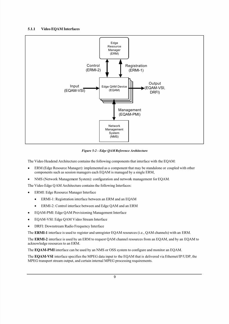
5.1.1 Video EQAM Interfaces
Edge QAM Device
(EQAM)
Edge QAM Device
(EQAM)
Edge QAM Device
(EQAM)
Edge
Resource
Manager
(ERM)
Edge QAM Device
(EQAM)
Network
Management
System
(NMS)
Input
(EQAM-VSI)
Output
(EQAM-VSI,
DRFI)
Control
(ERMI-2)Registration
(ERMI-1)
Management
(EQAM-PMI)
Figure 5-2 - Edge QAM Reference Architecture
The Video Headend Architecture contains the following components that interface with the EQAM:
• ERM (Edge Resource Manager): implemented as a component that may be standalone or coupled with othercomponents such as session managers each EQAM is managed by a single ERM,
• NMS (Network Management System): configuration and network management for EQAM.
The Video Edge QAM Architecture contains the following Interfaces:
• ERMI: Edge Resource Manager Interface
• ERMI-1: Registration interface between an ERM and an EQAM
• ERMI-2: Control interface between and Edge QAM and an ERM
• EQAM-PMI: Edge QAM Provisioning Management Interface
• EQAM-VSI: Edge QAM Video Stream Interface
•
DRFI: Downstream Radio Frequency InterfaceThe ERMI-1 interface is used to register and unregister EQAM resources (i.e., QAM channels) with an ERM.
The ERMI-2 interface is used by an ERM to request QAM channel resources from an EQAM, and by an EQAM toacknowledge resources to an ERM.
The EQAM-PMI interface can be used by an NMS or OSS system to configure and monitor an EQAM.
The EQAM-VSI interface specifies the MPEG data input to the EQAM that is delivered via Ethernet/IP/UDP, theMPEG transport stream output, and certain internal MPEG processing requirements.

7/26/2019 SCTE 137-7 2010.pdf
http://slidepdf.com/reader/full/scte-137-7-2010pdf 14/36
10
The DRFI interface specifies the MPEG data output from the EQAM that is delivered over an RF QAM channel.
5.2 M-CMTS Reference Architecture
The reference architecture for a Modular CMTS system that includes Video Sources and set-top boxes is shown inFigure 5-3. This architecture contains several pieces of equipment, along with interfaces between those pieces of
equipment. This section briefly introduces each device and interface.
Figure 5-3 - M -CMTS Reference Architecture
The Edge QAM device, or EQAM for short, has its origins in the VOD environment. It is a chassis that typicallyhas one or more gigabit Ethernet inputs coming in and multiple QAM modulators and RF upconverters on theoutput. This EQAM has been designed for use in a Modular CMTS environment. Each individual output of thesedevices is often referred to as a QAM Channel rather than the full "QAM Modulator and RF Upconverter." One ormore QAM channels may be included in the RF output of one physical port.
The M-CMTS Core contains everything a traditional CMTS does, except for functions performed in the EQAM.The M-CMTS Core contains the MAC-Layer functionality and all the initialization and operational DOCSIS-relatedsoftware. The MAC-Layer functionality includes all signaling functions, downstream bandwidth scheduling, andDOCSIS framing.
This diagram shows the Upstream Receivers for DOCSIS upstream channels located internally to the M-CMTSCore. However, there is nothing preventing an implementation of a Modular CMTS from using external upstreamreceivers.
The DOCSIS Timing Interface (DTI) Server provides a common frequency of 10.24 MHz and a DOCSIStimestamp to other M-CMTS elements.
DEPI, the Downstream External PHY Interface, is the interface between the M-CMTS Core and the EQAM. Morespecifically, it is an IP Tunnel between the downstream MAC in the M-CMTS Core and the downstream PHY in theEQAM. It contains both a data path for DOCSIS frames and a control path for setting up, maintaining, and tearingdown sessions.
DRFI, or Downstream Radio Frequency Interface, is intended to capture all the current and future RF requirementsfor the downstream direction for both integrated DOCSIS CMTS systems, Modular DOCSIS CMTS systems, andVOD EQAM systems.

7/26/2019 SCTE 137-7 2010.pdf
http://slidepdf.com/reader/full/scte-137-7-2010pdf 15/36
11
DTI, or DOCSIS Timing Interface, is a point-to-point interface from the DTI Server to other M-CMTS elements.The DTI Specification [SCTE 137-1] defines DTI Server and DTI Client behaviors and protocols. The DTI Server isthe Timing Signal Generator while each M-CMTS Core and EQAM has a DTI Client. The DTI Server distributes a10.24 MHz frequency and a DOCSIS timestamp over unshielded twisted pair (UTP). The DTI protocolautomatically compensates for cable length and ensures that all M-CMTS elements have the same sense of time andfrequency.
ERMI, or Edge Resource Manager Interface [SCTE 137-4], involves three interfaces: a registration interface(ERMI-1) between an EQAM and ERM (Edge Resource Manager), a control interface (ERMI-2) between anEQAM and an ERM, and a control interface (ERMI-3) between an M-CMTS Core and an ERM. The first interfaceis used to register and unregister EQAM resources (i.e., QAM channels) with an ERM. The second interface is used
by an ERM to request QAM channel resources from an EQAM and by an EQAM to deliver resources to an ERM.The third interface is used by the M-CMTS Core to request specific QAM channel resources from the ERM and bythe ERM to respond to such requests with the location of QAM channel resources.
MOSSI, or Modular CMTS Operations Support System Interface [SCTE 137-3], provides the management interfaceto each system component. This interface is an extension of the OSSI defined in the DOCSIS specifications formonitoring a management of CMTS functions. This interface could be used in place of an ERM and the ERMI tostatically configure and associate QAM channel resources with M-CMTS Cores. This interface allows for themodification of a QAM channel's physical layer parameter by either the M-CMTS Core or the EQAM and providesa mechanism by which the operator can "lock" certain parameters at the EQAM so that they can only be modified
there. This document defines the mechanism to communicate these parameter settings to the other side.
NSI, or the Network Side Interface is the physical interface the CMTS uses to connect to the backbone network.Today this is typically 100 Mbps or 1 Gbps Ethernet.
CMCI, or Cable Modem to Customer Premise Equipment Interface, is typically Ethernet or USB.

7/26/2019 SCTE 137-7 2010.pdf
http://slidepdf.com/reader/full/scte-137-7-2010pdf 16/36
12
6 ARCHITECTURAL ENTITIES
6.1 Edge Resource Manager
The ERM is responsible for managing and monitoring resources required at the edge for narrowcast sessions. The
Resource Manager may exist in any one of the following incarnations:• Standalone Edge Resource Manager (ERM),
• Resource Manager Process on the Global Session Resource Manager (GSRM),
• Resource Manager Process on the Switched Digital Video Manager.
Upon each session request from various application level session managers, the ERM will select one of the QAMchannels that have been registered with it to host the session. The QAM channel resources can be shared among alltypes of narrowcast services, such as VOD, SDV, and DOCSIS, with varying levels of bitrate and resourcerequirements. The algorithm for resource allocation is beyond the scope of this document, but it is recommendedthat the algorithm takes into consideration the following:
• Load balancing between the different QAM channels servicing a service group,
• QAM channels may be shared between multiple service groups,• Input stream bitrates may vary to cause fragmentation (i.e., inefficient algorithm will leave no room for a
high rate stream at high system usage),
• Various types of services or sessions within the same type of service may have a different level of policy,such as priority in case of high system usage.
The ERM maintains a mapping of input streams to QAM and program output.
The ERM maintains a session state; this information is used in various scenarios such as session manager recovery.
The ERM is able to monitor the EQAMs state, such as the keeping alive messages and allocating resourcesaccordingly.
The ERM is also provided with a group of EQAM and/or service groups that it controls. When the registration
messages reach the ERM from EQAM, the ERM only manages resources that it is provisioned to control.
6.2 EQAM
This component serves as a gateway between the IP network and the HFC network.
An EQAM is an edge device that receives packets of digital video or data from the IP network. It re-packetizes thevideo or data and delivers to the HFC network as an MPEG Transport Stream using RF QAM channel outputs.
The EQAM provides the following functionalities:
• Receiving multiple MPEG-2 SPTS streams over UDP/IP/GigE,
• Re-multiplexing MPEG-2 SPTS streams to MPEG-2 MPTS streams,
•
Re-stamping PCR timestamps for de-jitter processing,• QAM modulation and RF up-conversion.
The EQAM supports the following input types:
• Unicast video (VOD),
• Multicast video (Switched Digital Video),
• Modular CMTS (DOCSIS).

7/26/2019 SCTE 137-7 2010.pdf
http://slidepdf.com/reader/full/scte-137-7-2010pdf 17/36
13
6.3 M-CMTS Core
The M-CMTS Core contains everything a traditional CMTS does, except for functions performed in the EQAM.The M-CMTS Core contains the MAC-layer processing functions and all the initialization and operational DOCSIS-related software. The M-CMTS Core is typically an IP router.
6.4 DOCSIS Timing ServerThe DOCSIS Timing Interface (DTI) Server provides a common frequency of 10.24 MHz and a DOCSIS timestampto other M-CMTS elements.
The DTI Server establishes the reference for the timing distribution network and synchronizes all connected DTIClients via point-to-point connections between the server and each client. A single protocol initiated by the DTIserver permits the client to perform frequency and time synchronization. As shown, upstream receive, EdgeQAMs,and the M-CMTS CORE may have different uses for the synchronized frequency and time, but utilize a commonclient function.
6.5 NMS/OSS
The NMS will enable the operator to provide the configurations to the components and monitor the components
using SNMP and other protocols.
The NMS is responsible for:
• Configuration of non-volatile parameters of the EQAMs, such as RF settings (frequency, output level).
• DHCP/TFTP servers: the NMS should incorporate DHCP and TFTP servers. The servers will facilitate:
• IP addresses allocation,
• S/W versions management and download to the devices,
• Download of configuration to the EQAMs.
• Status monitoring, for monitoring the system health and prompt for any sub-system malfunctioning,
• Performance monitoring and statistics/reporting.

7/26/2019 SCTE 137-7 2010.pdf
http://slidepdf.com/reader/full/scte-137-7-2010pdf 18/36
14
7 BASIC EQAM OPERATION
7.1 Profiles
An EQAM can be any of three designated profiles:
• Video EQAM Profile: An EQAM of this profile supports EQAM requirements applicable to delivering digitalvideo and does not support DOCSIS M-CMTS EQAM requirements.
• M-CMTS EQAM Profile: An EQAM of this profile supports requirements applicable to a DOCSIS M-CMTSEQAM.
• Universal EQAM Profile: An EQAM of this profile supports requirements applicable to delivering digital videoand supporting DOCSIS M-CMTS EQAM requirements. Output QAM channels can be flexibly allocated todigital video delivery or DOCSIS high speed data service. It is not required that the Universal EQAM be able tomultiplex both digital video and DOCSIS data on the same QAM channel.
7.2 Interfaces
This section gives an overview of the various EQAM interfaces. Refer to Figure 5-1 and Figure 5-3.
7.2.1 ERMI
7.2.1.1 Edge QAM Registration (ERMI-1)
This interface allows the EQAM to register its configuration with ERMs that manage its resources. There may bemultiple destinations for ERMI-1. Each destination may be a different type, such as backup ERM or topologydatabase. The protocol used is the same.
This interface also provides EQAM status to the ERMs. The EQAM sends heartbeats to the ERM. An ERM mustnot allocate EQAM resources for new session requests that are located in an EQAM that has not reported itsheartbeat.
EQAM registration message includes QAM Name to QAM assignment, GigE IP input addresses, QAM bandwidth,
and QAM/RF parameters. It should also include a UDP port mapping to QAM and program for statically provisioned ports. The interfaces assigned for control signaling for the EQAM must also be included. Lastly, theregistration message must show to which QAM group the QAMs are associated.
To perform a graceful shutdown, the EQAM will use this interface to notify the ERM on status change tomaintenance. The ERM will not allocate new sessions via the QAMs that are in maintenance mode until the EQAMreports a status change to active.
Exception conditions such as bandwidth overflow, excessive jitter, or input signal loss may be reported to the ERM by the EQAM through the ERMI-1 interface.
In summary, the ERMI-1 interface provides the following key functionalities:
• EQAM advertises resource capability and report resource failure to the ERM:
• TSID
• Input ports
• Available bandwidth
• IP/Port addressing for ERM signaling
• EQAM provides heartbeat and reports resource failure.
• Protocols: extension to [RFC 3219] (TRIP).

7/26/2019 SCTE 137-7 2010.pdf
http://slidepdf.com/reader/full/scte-137-7-2010pdf 19/36
15
7.2.1.2 Edge QAM Control (ERMI-2)
This interface allows the ERM to allocate resources, such as QAM and bandwidth from EQAM, for each session.
During the EQAM control process, the ERM assigns the EQAM resources to each requested session based on theconfiguration and status information retrieved via the ERMI-1 interface and the ERM resource allocation algorithm.The control attributes also include output frequency and MPEG program numbers. The EQAM then ensures that any
data that arrives at the port is mapped to the proper QAM and program number.Switched Digital Video applications require the ERM to inform the EQAM to receive a multicast stream andinternally route it to several QAMs.
In summary, the ERMI-2 interface provides the following key functionalities:
• Dynamic resource signaling from ERM to EQAM
• Bandwidth
• Selection of input port
• Selection of QAM, frequency, and MPEG program number
• Input multicast or unicast address
•
Support multicast and unicast• Protocols: extension to [RFC 2326] (RTSP)
• Appropriate Conditional Access and Copy Control interfaces for encrypting and protecting a stream if EQAMhas embedded encryption capability.
7.2.2 EQAM-VSI
This interface specifies the input and output MPEG streams through the EQAM. It also defines the stream processing and performance requirements.
The EQAM-VSI input interface receives MPEG-2 stream that is encapsulated in UDP frames carried over IP/GigE.The MPEG streams are delivered to the EQAM in MPEG-2 SPTS or MPTS format using IP unicast addressing or IPmulticast sessions.
The EQAM-VSI output interface defines the MPEG-2 MPTS output from the Edge QAM. The MPEG transportstream coming out from each QAM has a TSID in its Program Association Table (PAT), which will assist in STBservice group discovery and validation.
In summary, the EQAM-VSI input and output interfaces provide the following key functionalities:
• EQAM-VSI Input: SPTS or MPTS over UDP/IP over GigE, IGMPv3
• EQAM-VSI Output: MPTS over QAM
• Processing and performance requirements
• Protocols: existing industry standard (SCTE/DVS/MPEG-2)
7.2.3 EQAM-PMI
This interface allows the configuration and monitoring of the EQAMs.
The NMS configures and monitors the EQAM using EQAM-PMI interface, which includes:
• Device detection
• Static configuration of the non-volatile memory of the EQAM
• Device IP/MAC (TFTP, DHCP)
• SNMP manager IP

7/26/2019 SCTE 137-7 2010.pdf
http://slidepdf.com/reader/full/scte-137-7-2010pdf 20/36
16
• Data warehouse and event reporting databases
• Discovery target IP addresses (ERMs, topology database)
• IP addresses from which it can receive MPEG streams
• Physical RF port labeling, as marked on the devices
• QAM carrier within the RF interface (output port)
• RF frequency
• QAM modulation
• QAM Name
• Activity state (On/Off/Reserved)
• TSID
• Group assigned to each EQAM input
• Status monitoring, using standard SNMP interface
• Performance/usage monitoring
• Encryption and Copy Control Status
• Session and Stream Status/Query
In summary, the EQAM-PMI interface provides the following key functionalities:
• Configuration: frequency, TSID, QAM name, interleaving etc.
• Monitoring: SNMP trap etc.
• Protocols:
• Configuration: XML over HTTP
• Monitoring: SNMPv3
7.2.4 DRFI
This document defines the downstream radio-frequency interface [SCTE 133] specifications for:
1. a video edgeQAM (EQAM),
2. an M-CMTS EQAM modular device,
3. an integrated Cable Modem Termination System (CMTS) with multiple downstream channels per RF port,or
4. an integrated CMTS beyond DOCSIS 2.0.
There are differences in the cable spectrum planning practices adopted for different networks in the world.Therefore, two options for physical layer technology are included, which have equal priority and are not required to
be interoperable. One technology option is based on the downstream multi-program television distribution that isdeployed in North America using 6 MHz channeling. The other technology option is based on the correspondingEuropean multi-program television distribution.
A DRFI-compliant device may be a single-channel only device or it may be a multiple-channel device capable ofgenerating one or multiple downstream RF carriers simultaneously on one RF output port. An EQAM may be amodule of a modular cable modem termination system (M-CMTS) and be used for delivering a high-speed dataservice or it may serve as a component of a digital video or video-on-demand (VOD) system, delivering high qualitydigital video to subscribers. These specifications are crafted to enable an EQAM to be used without restriction ineither or both service delivery scenarios simultaneously. "Simultaneous," in the early deployments, means that if an
7/26/2019 SCTE 137-7 2010.pdf
http://slidepdf.com/reader/full/scte-137-7-2010pdf 21/36
17
RF output port has multiple QAM channels, some channel(s) may be delivering high-speed data while some othersmay be delivering digital video. This specification enables future uses, wherein a single QAM channel may share
bandwidth between high-speed data and digital video in the same MPEG transport stream.
Conceptually, an EQAM accepts input via an Ethernet link, integrates the incoming data into an MPEG transportstream, modulates one of a plurality of RF carriers per these specifications, and delivers the carrier to a single RFoutput connector shared in common with all modulators. Conceivably, a single EQAM RF channel could be used for
data and video simultaneously. The reason that an EQAM RF channel can be used for either is that both digitalvideo and DOCSIS data downstream channels are based on ITU-T J.83 Annex B [ITU-T J.83-B] for cable networksin North America and EN 300 429 [EN 300 429] for cable networks deployed in Europe. On downstream channelscomplying to ITU-T J.83, Annex B, typically, the only difference between an EQAM RF channel operating in avideo mode and an EQAM RF channel operating in DOCSIS data mode is the interleaver depth (see Sections 6.3.1and 6.3.3). DOCSIS data runs in a low latency mode using a shallow interleaver depth at the cost of some burst
protection. DOCSIS data can do this because, if a transmission error occurs, the higher layer protocols will requestre-transmission of the missing data. For video, the sequence of frames in the program is both time sensitive andorder sensitive and cannot be re-transmitted. For this reason, video uses a deeper interleaver depth to provide moreextensive burst protection and deliver more of the program content without loss. The penalty video pays is inlatency. The entire program content is delayed by a few milliseconds, typically, which are invisible to the viewers ofthe program. The conflicting demands for interleaver depth are what prevent a single EQAM RF channel from beingused optimally for video and DOCSIS data simultaneously. A traditional integrated CMTS, however, is used solely
for DOCSIS data.
7.2.5 DEPI
DEPI is an IP Tunnel that exists between the DOCSIS MAC in the M-CMTS Core and the DOCSIS PHY that existsin the EQAM. DEPI's job is to take either formatted DOCSIS frames or MPEG packets, transport them through alayer 2 or layer 3 network, and deliver them to the EQAM for transmission.
The base protocol used for the DEPI is the Layer 2 Tunneling Protocol Version 3, or L2TPv3 for short [RFC 3931].L2TPv3 is an IETF protocol that is a generic protocol for creating a pseudowire. A pseudowire is a mechanism totransparently transport a layer 2 protocol over a layer 3 network. Examples of protocols supported by L2TPv3include ATM, HDLC, Ethernet, Frame Relay, PPP, etc.
Each data packet contains a 32 bit session ID that is associated with a single QAM Channel. The UDP header isoptional in the L2TPv3 protocol.
L2TPv3 then permits a sub-header to exist whose definition is specific to the payload being carried. The controlchannel allows for signaling messages to be sent between the M-CMTS Core and EQAM. Typical control messageswill set up a "control connection" between the M-CMTS Core and EQAM, and then set up multiple data sessions(one for each downstream QAM channel). Each session can be marked with different DiffServ Code Points(DSCPs), and support different encapsulation protocols.
There are two basic tunneling techniques defined by DEPI. The first technique, known as D-MPT mode, transportsmultiple 188-byte MPEG-TS packets by placing them into the L2TPv3 payload with a unique sub-header, whichcontains a sequence number so packet drops can be detected. The encapsulation of DOCSIS Frames into MPEG-TS
packets is performed in the M-CMTS Core. The second technique, known as the Packet Streaming Protocol (PSP),transports DOCSIS Frames in the L2TPv3 payload. The DOCSIS Frames are then encapsulated in MPEG-TS
packets within the EQAM. PSP mode allows DOCSIS frames to be both concatenated, to increase network performance, and fragmented, in case the tunneled packets exceed the network MTU size.
One of the technical considerations of the Modular CMTS architecture is its impact on the round trip request-grantdelay time. The request-grant delay time is the time from when a CM requests bandwidth using an uncontended
bandwidth request (REQ) to when it receives a MAP message with the granted transmit opportunity in it.
To prevent the MAP from being slowed down by other traffic in the CIN, the DOCSIS traffic (or a subset containingthe MAP messages) may be sent in an independent L2TPv3 flow that has a unique DSCP. The value of the markedDSCP value should be consistent with a configured "per hop behavior (PHB)" that will provide MAP messages withthe highest priority and lowest latency across the CIN to the EQAM.

7/26/2019 SCTE 137-7 2010.pdf
http://slidepdf.com/reader/full/scte-137-7-2010pdf 22/36
18
7.2.6 DTI
The DTI system requirements refer to the DOCSIS timing requirements as outlined in the DOCSIS Specifications.These requirements are presented independent of the CMTS architecture.
The specific sections of the DOCSIS specifications that are of interest are:
• Mini-slot Numbering
• Modulation (Chip) Timing Jitter for Synchronous Operation
• CMTS Timestamp Jitter
• CMTS Clock Generation
• CMTS Downstream Symbol Clock Jitter for Synchronous Operation
• CMTS Downstream Symbol Clock Drift for Synchronous Operation
• Timing and Synchronization
The DTI Server clock operates with the specifications detailed in section 7.1 of [SCTE 137-1], which integrates boththe DOCSIS timing system requirements and the existing legacy synchronization network clock consistent with[ITU-T G.812] and [T1.101]. This is done to ensure that the CM supporting T-Services can derive its clocking and
meet [ITU-T G.823] or [ITU-T G.824] jitter and wander requirements for both traffic-bearing and synchronization- bearing transport clock sources.
The M-CMTS Core element:
• Uses the DTI server master clock for creating a timestamp.
• Uses the timestamp for MAP generation.
The Edge QAM element:
• Uses the DTI server master clock for symbol rate generation.
• Uses the timestamp for inserting and/or correcting SYNC messages.
The Upstream receive element:
• Uses the timestamp and/or S-CDMA frame and the MAP for determining when to look for the start of a receive burst.
• Uses a clock locked to the master clock for reception of symbols in S-CDMA mode.
The DTI Server establishes the reference for the timing distribution network and synchronizes all connected DTIClients via point-to-point connections between the server and each client. A single protocol initiated by the DTIserver permits the client to perform frequency and time synchronization. As shown, upstream receive, Edge QAMs,and the M-CMTS Core may have different uses for the synchronized frequency and time, but utilize a commonclient function.
The DTI protocol and server-client interactions are described in detail in Sections 6 and 7 of [SCTE 137-1]. Theessential characteristics are:
• The DTI server initiates the protocol, which the DTI client uses to establish its time and frequency
synchronization.
• Using a ping-pong scheme, the client always immediately replies to the DTI server when it receives atransmission from the DTI server. The server uses this response to auto-compensate any delays with the effectthat the client becomes precisely synchronized to the server.
• The server-to-client-to-server handshake continually repeats, assuring that a tight synchronization can bemaintained.
The DTI protocol and components support accurate and robust transport of the server 10.24 MHz master clock and32-bit DOCSIS timestamp to the client within a node or building. The protocol is structured to minimize the

7/26/2019 SCTE 137-7 2010.pdf
http://slidepdf.com/reader/full/scte-137-7-2010pdf 23/36
19
complexity and cost of the client clocks and the per port cost of the shared server function while supporting all theDOCSIS S-CDMA, TDMA, and future T-Services timing requirements in a modular system.
The high accuracy (<5 ns) and high stability (<1 ns timing jitter budget) is achieved by using a simple ping-ponglayer 2 timing protocol over a single twisted pair connection that uses common passive PHY components in bothdirections. This structure provides delay reciprocity so that all cable delay processing can be performed in the server.The client’s role in delay correction is to provide a fixed delay response to the server frame and to use the cable
advance supplied by the server to advance the local 10 kHz DTI frame clock to correct for cable delay.
To ensure reliable transport and client clock operation, the client clock is required to report the current phase error ofits local clock (frame clock) with respect to the delay-corrected server frame clock. This measurement is reported tothe server at the 10 kHz frame rate. The server’s role is to process this measurement data and verify the client’stiming operation. This protocol supports real-time detection and mitigation of client clock faults.
The DTI client can be realized with a single digital component, a simple PHY, and a low cost local oscillator, asholdover and filtering are supported in the shared server. A common definition of the DTI high-speed clock isnecessary to ensure compatibility between all DOCSIS DTI client components.
The deployment of T-Services compliant with the existing Telco T1/E1 standards requires both synchronization andtraceability to a common external clock source. In this case, if a cable modem supporting T-Services is connected toan M-CMTS EQAM, the cable modem needs to be synchronized with the DTI Server operating with an external T-Service reference.
7.2.7 ERMI
The ERMI specification defines EQAM Resource Management protocols for video, M-CMTS, or universal EQAM.
Three interfaces are specified in this document:
ERMI-1: A registration interface between an ERM and an EQAM. This interface is used to register and unregisterEQAM resources (i.e., QAM channels) with an ERM.
ERMI-2: A control interface between an EQAM and an ERM. This interface is used by an ERM to request QAMchannel resources from an EQAM, and by an EQAM to acknowledge resources to an ERM.
ERMI-3: A control interface between an M-CMTS Core and an ERM. This interface is used by the M-CMTS Coreto request specific QAM channel resources from the ERM, and by the ERM to respond to such requests with the
location of QAM channel resources.

7/26/2019 SCTE 137-7 2010.pdf
http://slidepdf.com/reader/full/scte-137-7-2010pdf 24/36
20
8 MODULAR CMTS INTERFACE AND VIDEO EQAM DOCUMENTS
A list of the documents in the Modular CMTS Interface Specifications family is provided below.
8.1 Modular CMTS Interface Documents
8.1.1 DRFI
This document defines the downstream radio-frequency interface [SCTE 133] specifications for:
1. a video EQAM,
2. an M-CMTS EQAM,
3. a Universal EQAM,
4. an integrated Cable Modem Termination System (CMTS) with multiple downstream channels per RF port,or5. an integrated CMTS beyond DOCSIS 2.0.
8.1.2 DEPI
This document defines an interface known as the Downstream External PHY Interface [SCTE 137-2] and associated protocol requirements for the transport of downstream user data between the M-CMTS Core and the M-CMTS orUniversal EQAM. It describes the characteristics of the DEPI interface, provides requirements that must be met bythe M-CMTS Core, the M-CMTS EQAM, and Universal EQAM, and also describes various aspects of technicalissues that are involved in the implementation and deployment of a DOCSIS system using the M-CMTSarchitecture.
This specification does not address any traditional MPEG-based video requirements. Those requirements can befound in the EQAM VSI specification.
8.1.3 DTI
The DTI specification contains requirements for a DTI Server as well as a DTI Client. The M-CMTS Core, the M-CMTS EQAM, and the Universal EQAM are required to implement the DTI Client functionality.
The requirements for timing and synchronization of the DOCSIS system come from the following areas.
• Existing DOCSIS Specification & ATP Requirements
• Remote PHY System Requirements
• Implementation Requirements
• Emerging Services like T-Services and wireless
These requirements place definitions and constraints on the use of the 10.24 MHz DOCSIS master clock and theDOCSIS timestamp, which is delivered in the SYNC message. The DOCSIS specification originally envisioned theM-CMTS Core, EQAMs, and upstream receive functions on one assembly, fed with a common clock. Thetimestamp counter resided in the M-CMTS Core function.
The M-CMTS Remote PHY architecture may result in three components: the M-CMTS Core, the upstream receiver,and the EQAM being located in a different chassis, and potentially at different physical locations. As a system, thethree components comply with the DOCSIS specification and any existing CMTS equipment.
The DOCSIS Timing Protocol (DTI) defined in this document, supports the accurate and robust transport of the DTIserver 10.24 MHz master clock, 32-bit DOCSIS timestamp, and Time of Day, to the DTI client within the DOCSISM-CMTS cable network. The DTI protocol is structured to minimize the complexity and cost of the DTI clientclocks and the per port cost of the shared server function while supporting all SCDMA and TDMA timingrequirements.

7/26/2019 SCTE 137-7 2010.pdf
http://slidepdf.com/reader/full/scte-137-7-2010pdf 25/36
21
8.1.4 ERMI
This document specifies interfaces used by EQAMs (all profiles), Edge Resource Managers (ERMs), and M-CMTSCores within the context of a Modular Headend Architecture. Three interfaces are specified in this document:
ERMI-1: A registration interface between an ERM and an EQAM. This interface is used to register and unregisterEQAM resources (i.e., QAM channels) with an ERM.
ERMI-2: A control interface between an EQAM and an ERM. This interface is used by an ERM to request QAMchannel resource from an EQAM, and by an EQAM to deliver resources to an ERM.
ERMI-3: A control interface between an M-CMTS core and an ERM. This interface is used by the M-CMTS core torequest specific QAM channel resources from the ERM, and by the ERM to respond to such requests with thelocation of QAM channel resources.
While ERMI is considered required functionality for Video and Universal EQAMs, it is considered optionalfunctionality for M-CMTS EQAMs and M-CMTS Cores.
8.1.5 M-OSSI
This specification defines the Network Management requirements to support a Modular Cable Modem TerminationSystem (M-CMTS) for headend components compliant to DOCSIS.
The purpose of this document is to define the management requirements for the M-CMTS architecture that enablesan effective operation of the M-CMTS components. In particular, this specification defines the configuration,monitoring, and performance requirements of the M-CMTS Core and DTI Server for the Modular CMTS interfaces.
The Operations Support Systems requirements of the M-CMTS architecture consist of the Management InformationBase (MIB), residing in the M-CMTS modules other than the EQAM (such as M-CMTS core and DTI Server), withthe purpose of providing configuration, monitoring, and troubleshooting management functions of the M-CMTSinterface specifications.
8.1.5.1 M-CMTS Core Management Requirements Overview
The M-CMTS Core Management requirements are of two types:
• M-CMTS Core supports standard OSSI CMTS requirements, as specified in [OSSI].
• M-CMTS Core supports the M-CMTS OSS requirements defined by this specification.For M-CMTS Core-compliant devices, conflicts of M-CMTS OSSI requirements and OSSI CMTS requirements areresolved by the prevailing M-CMTS OSSI requirements. The M-CMTS Core compliant device supports M-CMTSOSSI requirements over OSSI CMTS requirements in case those requirements are in conflict.
M-CMTS OSSI requirements for the M-CMTS Core are summarized below:
• Requirements for Downstream RF Interface Specification [SCTE 133]
• Requirements for DOCSIS External PHY Interface [SCTE 137-2]
• Requirements for DOCSIS Timing Interface [SCTE 137-1]
8.1.5.2 DTI Server Management Requirements Overview
The management requirements for the M-CMTS DTI Server-compliant device are specified in [SCTE 137-3] andsummarized as:
• Requirements for DOCSIS Timing Interface [SCTE 137-1], and
• SNMP and Management Information MIB requirements.

7/26/2019 SCTE 137-7 2010.pdf
http://slidepdf.com/reader/full/scte-137-7-2010pdf 26/36
22
8.2 Video EQAM Interface Documents
Some of the originating material for the Video EQAM documents arose out of earlier-generation video systemdocumentation and requirements documents from various cable operators. The final output are the followingspecifications.
8.2.1 ERMI Specification
For a Video EQAM, the purpose of the this document is to specify a mechanism for an ERM to discover EQAMresources via a registration interface (ERMI-1 interface) and to define resource allocation interfaces for an ERM toallocate QAM resources from an EQAM (ERMI-2 interface).
8.2.2 EQAM VSI Specification
The purpose of this document is to specify the Edge QAM Video Stream interface, which defines a set ofoperational modes and functions that cover the reception (via Ethernet), de-jittering, PID and program numberremapping, multiplexing, PSI re-generation, null stuffing, PCR correction, and transmission of MPEG videotransport streams.
The scope of this specification is limited to the Edge QAM Stream interface operated in a narrowcast environmentfor digital video applications, such as Video on Demand (VOD) and Switched Digital Video (SDV). This
specification is considered mandatory functionality for Video and Universal EQAMs.
8.2.3 EQAM PMI Specification
The purpose of this document is to specify the Edge QAM Provisioning and Management interface. This interfaceoperates between the Edge QAM and the various control and management components in a Headend and/or Hub.
The scope of this specification is limited to the Edge QAM management interface operated in a narrowcastenvironment for digital video applications, such as Video On Demand (VOD) and Switched Digital Video (SDV).
EQAM-PMI will be incorporated into an EQAM Provisioning and Management specification that includes MIBsfrom the M-OSSI document and the definition of EQAM-PMI.
8.3 Summary of Specification Applicability
The following table summarizes the Modular Headend Architecture devices and the specification documents thatapply.
Table 8–1 - MHA Specification Applicability
Specification
Device DEPI DTI M-OSSI ERMI PMI VSI
Video EQAM M M M
Universal EQAM M M M M M
M-CMTS EQAM M M O M
M-CMTS Core M M M ODTI Server M M
ERM M
M = MandatoryO = Optional

7/26/2019 SCTE 137-7 2010.pdf
http://slidepdf.com/reader/full/scte-137-7-2010pdf 27/36
23
Appendix I Digital Video Background
This section describes the transporting and structure of digital content driving the interface and EQAM functionalrequirements.
I.1 Video Transport
MPEG content (MPEG2, H.264/MPEG4/AVC) employs various techniques to encode the multimedia data it iscomposed of and compress the bandwidth intensive video. For the purposes of this description, the noteworthyattribute of the encoding of the digital content is that it takes up far less bandwidth than a similar analog encodingwould take. This has significance to the transport of the MPEG program from the headend to the subscriber. Thisdescription will not focus on the encoding or compression techniques.
The term MPEG program is often used to refer to the set of elements that compose one coherent MPEG presentation. For example, the audio and video for a news broadcast encoded as MPEG could be called an MPEG program. The sub-elements of the MPEG program are referred to as elementary streams. An elementary streammight be a presentation component, such as the video, audio or subtitles. An elementary stream data can be used toaid in the presentation of the data, such as the program clock reference that synchronizes the various presentationstreams. The elementary stream could be just data used for various purposes, such as describing the program in textor watermarking the program.
A device receiving an MPEG program for display must be able to recognize each elementary stream and direct it tothe appropriate internal function for processing. For that reason, each elementary stream is tagged with an identifiercalled a program identifier or PID. When the elementary streams are transported over the medium (e.g., GigE or RFcable), they are encapsulated or packetized into a transport packet.
Figure I–1 - Transport Packet
7/26/2019 SCTE 137-7 2010.pdf
http://slidepdf.com/reader/full/scte-137-7-2010pdf 28/36
24
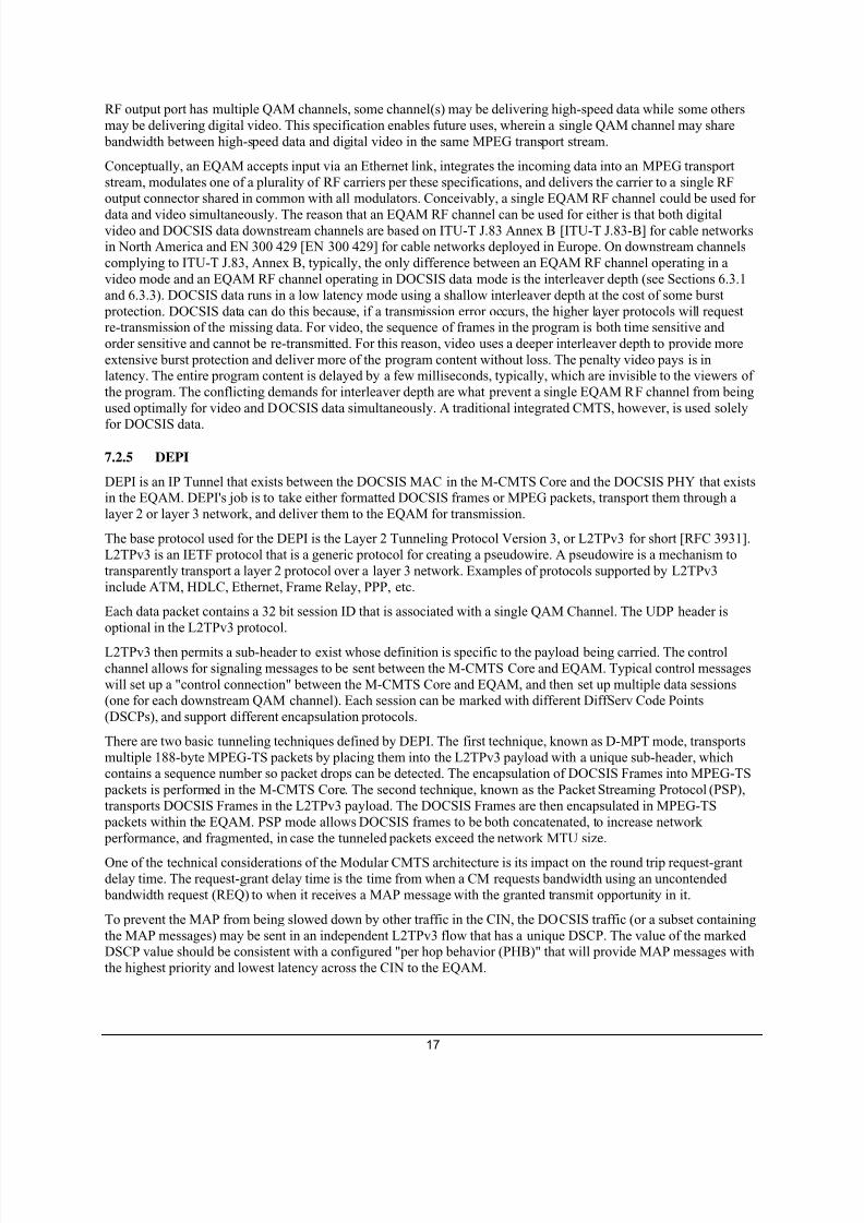
The process in which many transport packets are being transmitted over the medium is called a transport stream.
Figure I–2 - IP Transport Stream
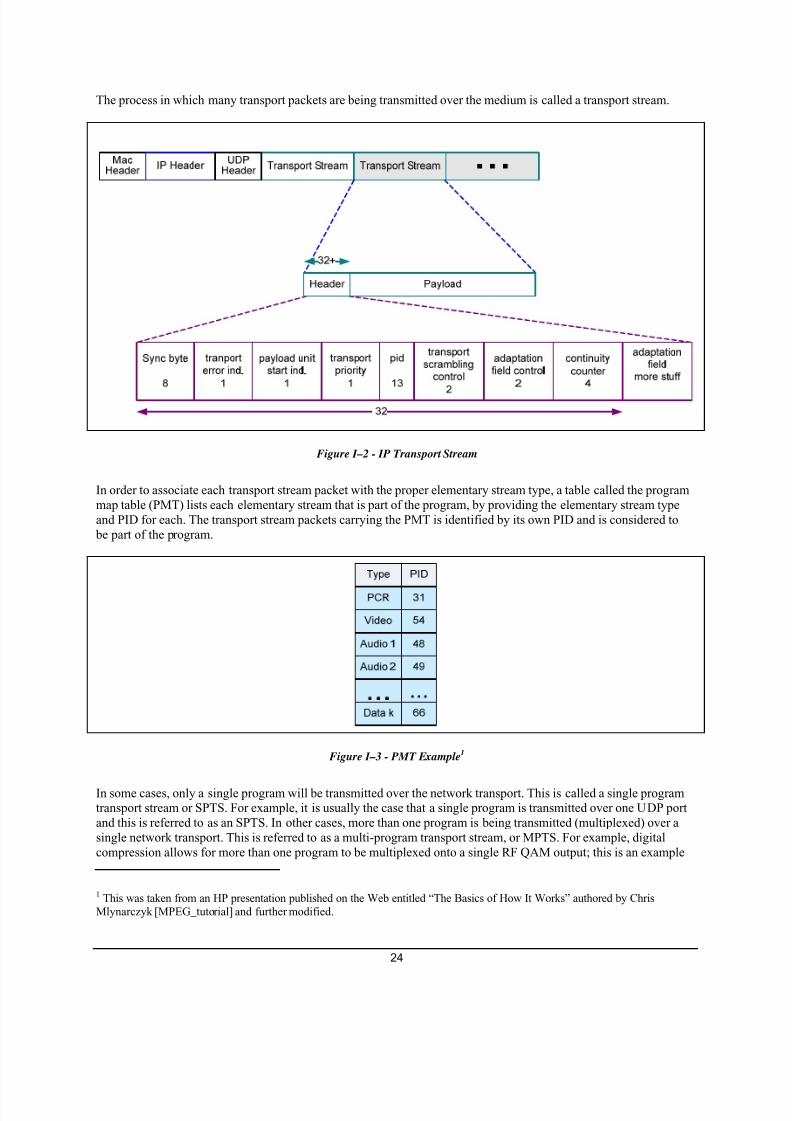
In order to associate each transport stream packet with the proper elementary stream type, a table called the programmap table (PMT) lists each elementary stream that is part of the program, by providing the elementary stream typeand PID for each. The transport stream packets carrying the PMT is identified by its own PID and is considered to
be part of the program.
Figure I–3 - PMT Example1
In some cases, only a single program will be transmitted over the network transport. This is called a single programtransport stream or SPTS. For example, it is usually the case that a single program is transmitted over one UDP portand this is referred to as an SPTS. In other cases, more than one program is being transmitted (multiplexed) over asingle network transport. This is referred to as a multi-program transport stream, or MPTS. For example, digitalcompression allows for more than one program to be multiplexed onto a single RF QAM output; this is an example
1 This was taken from an HP presentation published on the Web entitled “The Basics of How It Works” authored by ChrisMlynarczyk [MPEG_tutorial] and further modified.

7/26/2019 SCTE 137-7 2010.pdf
http://slidepdf.com/reader/full/scte-137-7-2010pdf 29/36
25
of an MPTS. Therefore, there is a mechanism, called the program association table or PAT, for identifying all the programs that are multiplexed into an MPTS. Each program in the MPTS is identified by a program number, and thePID where that program's PMT can be found is listed.
Program Map Table for Program 1
PCR
Data k
Audio 2
Audio 1
Video
31
66
49
48
54
Program 1
Program k
Program 3
Program 2
PID=16
PID=55
PID=33
PID=22
Program Association Table (always PID 0)PCR
Data k
Audio 2
Audio 1
Video
41
88
82
81
19
Program Map Table for Program 2
Type PID
Figure I–4 - PAT Example 2
The transport stream packet containing PAT is always found at PID 0. This allows a receiving device to find all the programs in an MPTS by decoding the PAT from this well-known PID. Once the PAT is decoded, the receivingdevice can then find the PID of the selected program's PMT, and thus find each elementary stream of the program.
Figure I–5 - MPTS Example
2
The EQAM is receiving one or more MPEG SPTSs and/or MPTSs over UDP and outputting an MPTS over QAMmodulated RF. The source of each input transport stream is not aware of the other transport streams that will bemultiplexed by the EQAM, and consequently, the PIDs used in the various input transport streams might conflict.For that reason, the EQAM might be configured to remap the PIDs from the original SPTS to a new set that has noconflicts. This requires changing the PIDs used in the incoming transport stream headers and updating the PMT foreach program to use the new PID numbers. It is sometimes the case, however, that the incoming PIDs must be usedunchanged, and, therefore, it is necessary to disable PID remapping for a specific QAM channel. When PIDremapping is disabled, the onus is on the operator to ensure that the source of each transport stream utilizes a uniqueset of PIDs so that conflicts don't arise on the output transport stream.
Certain applications require multiplexing or transport stream processing functions that are beyond the capabilities ofthe EQAM. For these applications an external transport stream processor can be used, and an entire MPTS thatmatches the data rate of the QAM channel can be input to the EQAM for direct modulation on a QAM channel. Thismode of operation is known as "MPTS Passthrough." In MPTS Passthrough mode, the EQAM performs very little
processing of the input MPTS (notably PCR correction and TSID remarking).
2 This was taken from an HP presentation published on the Web entitled “The Basics of How It Works” authored by ChrisMlynarczyk [MPEG_tutorial] and further modified.

7/26/2019 SCTE 137-7 2010.pdf
http://slidepdf.com/reader/full/scte-137-7-2010pdf 30/36
26
In addition, there must be a mechanism for the EQAM to identify the RF/QAM output and output program numberto associate the program to as it receives the IP/UDP SPTS. This is done by mapping the destination UDP port in theincoming IP packet to an RF output and program number; in a sense, making the UDP port identify the stream to theEQAM. In early implementations of EQAM, products had static mappings of UDP ports to output RF ports and
program numbers. This has sometimes been referred to as static setup mode because the mapping is known ahead oftime; therefore, no explicit mapping must be created at session creation time. In the other model, called dynamicsetup mode, the mapping between UDP port and RF output port and program number is dynamically provisioned bythe ERM at session setup time. Some EQAMs only support one mode of operation at a time (static or dynamic),while others can support both modes simultaneously.
I.2 Broadcast and Narrowcast Services
The new important characteristic of the cable network is that it is now bi-directional, allowing data to transitdownstream from the headend to the home and transit upstream from the home to the headend.
Bi-directional (sometimes called two-way) traffic flow in the cable network enables Video on Demand (VOD), aservice that allows a subscriber to request (upstream) a pre-packaged MPEG content be delivered (downstream) tothe CPE STB and control the MPEG stream (upstream) to allow fast forward, pause, rewind, and stop. VOD isnarrowcast, usually only being received by one subscriber.
As more digital services were deployed, a more cost-effective method to transport digital data from the source outtoward the Cable subscribers became needed. This gave rise to the ASI device that didn’t require the RF hardware,had a four-fold capacity increase from RF/QAM, could be carried over coaxial cable, and was a proven technologyfor carrying digital data over a serial carrier. The ASI device would accept ASI carrying SPTS or MPTS and outputRF/QAM. This was the first widely deployed cable edge device.
Later, ASI would begin being replaced by Ethernet as Ethernet’s capacity eclipsed ASI, Ethernet’s ubiquity drovedown equipment prices, and flexibility offered by IP became apparent. The transition to Ethernet resulted in the firstgeneration of devices that would eventually become the Universal Edge QAM, having the common characteristicsof receiving MPTS over IP/UDP and output RF/QAM.
VOD applications leverage the IP EQAM by emitting IP unicast SPTS to the edge device, which multiplexed theminto the RF/QAM.
As more and more digital services consuming more and more bandwidth have been deployed, MSOs have found a
need to use its RF bandwidth more efficiently. A technology described in ISO/IEC 13818-6 in 1998 called switcheddigital broadcast (SDB) has been resurrected under the moniker switched digital video (SDV). The main idea behindSDV is to transmit channel programs to only those service areas where there is a subscriber viewing the channel.Again, bi-directional data transmission is a key element to the support of this digital narrowcast service.

7/26/2019 SCTE 137-7 2010.pdf
http://slidepdf.com/reader/full/scte-137-7-2010pdf 31/36
27
Figure I–6 - non-SDV versus SDV Program Streaming
Figure I–5 shows an example of the difference of how streams might be forwarded in a cable network in a non-SDVversus SDV topology. In this example, the headend is the program source and the HUBs are where the EQAMswould be receiving the program for distribution. In the top diagram, all the program channels are received by theHUB and distributed to all service groups regardless of whether any home is viewing them. In the bottom of the
diagram, only the programs that are being viewed are distributed beyond the hub.
SDV uses the IP protocol differently than the VOD. SDV programs are multicast to the IP network, where the edgedevice can choose to receive the SPTS and forward it to the appropriate RF/QAM.
The cable network has evolved from a pure analog broadcast network over RF to a largely digital narrowcastnetwork supporting various digital video services.

7/26/2019 SCTE 137-7 2010.pdf
http://slidepdf.com/reader/full/scte-137-7-2010pdf 32/36
28
I.3 VOD Use Case
The VOD application demonstrates the unicast use case for video EQAMs. Some of the control flow is presentedhere to illustrate how VOD fits into the video network and interacts with EQAMs. The setup of a VOD streamillustrates the key concepts. Note that this is an example flow and is not normative to the specifications.
Figure I–7 - VOD Use Case Setup Sequence
Step 1: In step one of the session setup, the VOD client sends a setup request to the VOD session manager. Thesetup includes the content to stream and the service group, identifying the location of the STB in the network.
Step 2: The VOD session manager requests bandwidth of the ERM. The QAM group provided associates a set ofQAMs to the service groups. The session manager looks up information about the content to derive the bandwidthneeded to stream the content.
Step 3: The ERM selects the QAM on an Edge QAM device that has sufficient bandwidth.
Step 4: The ERM provisions the EQAM to prepare to receive and forward the stream. In this case QAM and program number are associated with the destination UDP port.
Step 5: The ERM returns the IP address of the Edge QAM device and a UDP port to where the VOD server shouldsend the SPTS. The ERM also provides the frequency on which the MPEG program will be transmitted and the
program number within the QAM RF corresponding to the program.
Step 6: The Session manager returns the frequency to the VOD client that the STB should tune to. The sessionmanager also returns the program number the STB should select to present the correct stream.
Step 7: The VOD client then directs the VOD session manager to start streaming the content program.
Step 8: The VOD session manager directs the VOD server to create a stream for the content and begin to stream.
Step 9: The VOD server (that might be independent of the VOD session manager) then streams the content toselected EQAM by directing the SPTS to the IP address of the EQAM and sending on the destination UDP port thatcorresponds to the RF output port serving the selected frequency and program number passed into the EQAM instep 4.

7/26/2019 SCTE 137-7 2010.pdf
http://slidepdf.com/reader/full/scte-137-7-2010pdf 33/36
29
Step 10: The EQAM directs the stream to the RF output based on the destination IP UDP. The EQAM multiplexesthe program into the QAM MPTS based on the program number passed in step 4. The VOD client receives the
program.
I.4 SDV Use Case
The SDV application demonstrates the multicast use case for video EQAMs. Some of the control flow is presentedhere to illustrate how SDV fits into the video network and interacts with EQAMs. The setup of an SDV programillustrates the key concepts. Note that this is an example flow and is not normative to the specifications.
ERMSDVSM EQAM SDV Client
1. Channelchange(channel, servicegroup)
3. selectQAM(qamgrp ,mcas tIP, mcastPort, bw)
8. SessionSetup (frequency, programNumber )
SDV client on the STB signalsthe SDVSM to tune to a new
channel.
SDV SM requests a bandwidthfor the channel program.
The EQAM joins the multicastIP address and port of the
channel.
0. MPEG2TS/UDP
9 . MPEG2/QAM
7. SessionSetup (frequency, pn)
2 . SessionSetup (qamgrp, mcastIP, mcastUDP,bw)
4. SessionSetup (mcastIP, mcastUDP, bw, destPort)
Initial condition is channels are
being multicast.
6. MPEG2 TS/UDP
The ERM responds with the
frequence and program number
of the program.
The session manager responds
to the SDV client with the
frequency and program number.
Multicast Server
The ERM selects a QAM with
sufficient bandwidth and directsthe EQAM to apply the
bandwidth to the multicast source.
5. join(mcastGrpIP, mcastSrcIP)
Figure I–8 - SDV Use Case Channel Change Sequence
Initial 0: The initial condition is that SDV channels are being IP multicast out to the network.
Step 1: The SDV client on the STB sends a channel change request to the session manager.
Step 2: The session manager requests bandwidth and a QAM channel for SDV program. The session manager provides the multicast source IP and UDP port of the program stream, the potential group of QAMs that can reachthe STB service group, and the bandwidth needed for the channel.
Step 3: The ERM selects the QAM on an Edge QAM device that has sufficient bandwidth.
Step 4: The ERM provisions the EQAM to prepare for to receive and forward the stream. In this case, ERM provides the multicast group IP and source IP of the program stream, the bandwidth needed for the channel, and thedestination RF QAM output channel and program number.
Step 5: The EQAM joins the multicast source and begins accepting the multicast IP SPTS.
Step 6: The EQAM begins sending the program out the QAM channel MPTS that can reach the STB.
Step 7: The ERM returns to the session manager the frequency and program number the program will be carried in.

7/26/2019 SCTE 137-7 2010.pdf
http://slidepdf.com/reader/full/scte-137-7-2010pdf 34/36
30
Step 8: The Session manager returns to the SDV client the frequency and program number the STB should tune toreceive the SDV channel.
Step 9: The client begins to accept the program and present it.

7/26/2019 SCTE 137-7 2010.pdf
http://slidepdf.com/reader/full/scte-137-7-2010pdf 35/36
31
Appendix II DOCSIS/High Speed Data Background
Cable television operators have transitioned from a traditional core business of entertainment programming to a position as full-service providers of video, voice, and data telecommunications services. Cable modems based onData-Over-Cable Service Interface Specifications (DOCSIS) are among the fundamental devices making this
transition possible. To date, the most successful and cost-effective method for providing high-speed data services isvia cable modems compliant with the DOCSIS specifications.
Cable modems are devices at the subscriber premises that convert digital information into a modulated radiofrequency (RF) signal in the upstream direction and convert the RF signals to digital information in the downstreamdirection. Another piece of equipment, called a cable modem termination system (CMTS), performs the converseoperation for multiple subscribers at the cable operator's headend.
With more than 25.4 million high-speed Internet access customers in North America, the cable modem has becomethe broadband connection of choice for many Internet users. In fact, cable modem deployments have outstripped thenearest rival broadband technology, digital subscriber line (DSL), by a significant margin. Yet there is still room forgrowth since the total penetration of broadband access technologies in the U.S. is currently only 40 percent (allstatistics are as of Q3 2005, Kinetic Strategies, Inc.).
The four successive versions of the DOCSIS cable modem: DOCSIS 1.0, DOCSIS 1.1, DOCSIS 2.0, and DOCSIS
3.0, provide increasing levels of capabilities and functionality, while maintaining multi-vendor interoperability andfull backward and forward compatibility of DOCSIS.
The following describes major features introduced by each DOCSIS version:
• DOCSIS 1.0 provides basic broadband Internet connectivity for one or more devices in the home. Amongother things, it includes the ability to rate-limit (cap) a particular customer's data rate to a cable operatorselected value.
• DOCSIS 1.1 provides improved operational flexibility, security, and quality-of-service (QoS) features.
• DOCSIS 2.0 includes increased upstream reliability and throughput for symmetric services.
• DOCSIS 3.0 provides a number of enhancements, most notably, channel bonding, support for IPv6, andsupport for IPTV. Channel bonding provides cable operators with a flexible way to significantly increasedownstream speeds to a minimum of 160 Mbps, and upstream throughput up to a minimum rate of 120Mbps to customers.
The following benefits are achieved with respect to various DOCSIS versions:
• DOCSIS 1.0 cable modems made the interoperability of cable technology a reality for cable operators andcable subscribers.
• DOCSIS 1.0 made the standardization of cable modems possible. As a result, there was downward pressure placed on cable modem prices, causing them to drop by a factor of at least 10.
• DOCSIS 1.1 enables the cable operator to configure guarantees on the data rates and/or the latency of theservice.
• DOCSIS 2.0 increases upstream throughput to 30 Mbps of capability.
• DOCSIS 3.0 allows cable operators to provide data rates in the hundreds of megabits and, potentially,gigabits per second.

7/26/2019 SCTE 137-7 2010.pdf
http://slidepdf.com/reader/full/scte-137-7-2010pdf 36/36
The following services are enabled with respect to various DOCSIS versions:
• DOCSIS 1.0 provides the cable industry-platform the delivery of high-speed data on cable modems.
• DOCSIS 1.1 paves the way for high-quality digital voice, interactive gaming, and commercial service levelagreements (SLAs).
• DOCSIS 2.0 increases upstream throughput, resulting in an increase in the capacity to deliver high-speeddata.
• DOCSIS 3.0 enables direct competition with VDSL and FTTx service offerings from the telcos, and provides a platform for the evolution of the cable video business into IPTV.