schmidt pneumaticpress · 24 | schmidt ® presses press type 20 press type 23 press type 24 press...
TRANSCRIPT

Simply the best! | 21
SCHMIDT ® PneumaticPressMaximum Pressing Force from 1.6 kN to 60 kN / 350 lbs. to 13,490 lbs.
SCHMIDT ® PneumaticPresses consist of a modular system suit-
able for optimal transforming, joining and assembling operations
within the pressing capacities of 1.6 to 60 kN / 350 lbs. to 13,490
lbs.
With the addition of the SCHMIDT ® PressControl 75 or 600 and
the optional process monitoring, these presses become EC type-ap-
proved, CE-conformed workstations. Therefore these press systems
can be used in either single cycle mode or automatic mode.
The application determines the selection of the press system. Con-
taking into account ergonomic and safety aspects. These charac-
these press systems have been proven many times, in single applica-
tions, semi-automated assembly systems and have been integrated
into automated production lines.

1
2
3
4 5
6
7
22 | SCHMIDT ® Presses
1 Cylinder Unit
-
-
stroke.
2 Press Head Unit
The working height can be rapidly and accurately adjusted due
to the height adjustment’s ease of use. Can be used without the
frame as processing station in automated installations.
3 Pneumatic Control Package
Two-channel pneumatic package (as shown) is based on a mod-
air, supply pressure range of 3 – 6 bar / 44 – 87 psi.
4 Force Control
The press force output can easily be controlled via a separate
pressure regulator and pressure gauge (not shown).
5 Ram
With precision bore for tool holding and built-in adjustable stop.
6 Frame
With precision machined press head guide rails.
7 Fixture Mounting Plate
With precision T-slot and bore for tool location.
SCHMIDT® PneumaticPressExample Of a System Design With a Direct Acting Press

5
6
10
7
2
4
3
1
9
8
Simply the best! | 23
Functional Description Using Of a 3-Chamber Pneumatic
Cylinder – As An Example
In working stroke, three pistons 7 connected by the piston rod 6 are pressurized with compressed air via air connection 1
and move downward. The air below the pistons exhausts from the
cylinder chambers via depressurized connection 2 and breather
vents 3 and 4 . The ram 5 extends up to the maximum working
stroke.
In return stroke, the upper cylinder chambers are depressurized via
connection 1 and only the bottom piston is pressurized with com-
pressed air via air connection 2 . Ambient air enters in both remain-
ing cylinder chambers via breather vents 3 and 4 . The ram with
the three pistons moves upward.
This construction has the same effect as a parallel connection of
three cylinders. Thus, a powerful working stroke is achieved with
a compact design as well as an economic use due to the low air
consumption in the return stroke.
The stroke can be limited by setting Stroke Limit Block 8 to an
approximate, desired position. The gap between Stroke Limit Block
and Stroke Fine Adjustment 9 now determines the maximum stroke
-
justment Nut 9 can be adjusted.
All direct acting presses have a built-in permanent magnet 10 . This
magnet facilitates sensing of the ram position via tie rod mounted
sensors.
Features
Optimally adapted to individual requirements due to its modular
design
Process optimization by means of adjustable parameters (stroke,
force, speed)
Easy adaptation to different tool and part heights because of
easy stroke and height adjustment
Additional safety measures when using heavy tools due to the
optional device for retention of ram in home position
Optional end position request via cylinder switch as signal
transmitter for peripheral processes
Low noise level (< 75 dBA)
Double-acting, wear-resistant cylinders with low air consumption for
the return stroke
coated bushings at top and bottom of cylinder
Precision ground ram
Precision double ram guides
SCHMIDT ® PneumaticPressPrinciple Of Operation

24 | SCHMIDT ® Presses
Press Type 20 Press Type 23 Press Type 24 Press Type 25
Features
Round anti-rotational ram
Adjustable ram position in BDC by means of precision lower
stop (1 division line = 0.001 inch) on scale
SCHMIDT® PneumaticPressDirect Acting With Constant Force Over The Entire Stroke
Pneumatic Cylinder
with piston and magnet kit
for ram position via cylinder
switch.
Pushing force (lbs)
Op
era
tio
nal p
ress
ure
(p
si)
0 224 670 1,120 1,560 2,460 2,900 3,350
Working area with standard control block
with force output preselector
0
14
29
43
58
72
87
2,010
25242320

Simply the best! | 25
Frame Overview Press TypeFrame Height
M (inch)Table SizeB x T (inch)
Table BoreD Ø mm
Table HeightK (inch)
Mounting Surface B x L (inch)
No. 3 20, 23, 24, 25 21.25 5.90 x 4.33 20H7 2.36 5.90 x 10.23
No. 2 20, 23, 24, 25 27.55 7.28 x 4.33 20H7 2.36 7.28 x 11.02
No. 2-600 20, 23, 24, 25 38.34 7.87 x 6.29 20H7 3.85 7.87 x 11.41
No. 2-1000 20, 23, 24, 25 55.51 7.87 x 6.29 20H7 3.85 7.87 x 11.41
Press Type 20 23 24 25
Working stroke A mm
50, 75100, 125160, 200250, 300
50, 75100, 125160, 200250, 300
50, 75100, 125
160
50, 75100
Nominal force at 87 psi lbs 360 945 1,890 2,800
Throat depth C inch 3.38 3.38 3.38 3.38
Throat depth frame inch4.37, 5.156.29, 7.87
4.37, 5.156.29, 7.87
4.37, 5.156.29, 7.87
4.37, 5.15
suitable for throat depth frame
Ram bore Ø mm 20H7 20H7 20H7 20H7
Ram diameter Ø inch 1.57 1.57 1.57 1.57
Working height 1) F
Frame No. 3 inch 3.14 - 8.66 3.54 - 8.26 3.54 - 8.26 3.54 - 8.26
Frame No. 2 inch 4.33 - 14.17 4.72 - 13.77 4.72 - 13.77 4.72 - 13.77
Frame No. 2-600 inch 7.87 - 23.62 8.26 - 22.83 8.26 - 22.83 8.26 - 22.83
Frame No. 2-1000 inch 12.99 - 40.94 13.18 - 40.15 13.18 - 40.15 13.18 - 40.15
Weight approx. lbs 66 77 88 99
Flange model 20-FL 23-FL 24-FL 25-FL
Cylinder Z Ø inch 2.71 4.17 4.17 4.17
Flange FL Ø inch 4.33 5.51 5.51 5.51
SW inch 3.14 4.40 4.40 4.40
Centering shoulder ZA Ø inch 2.36 2.67 2.67 2.67
From 1.6 kN to 12.5 kN / 360 lbs. to 2,800 lbs.
Options
Additional charge applies1) Typical values; can vary ± 0.118 inch due to cast and production
tolerances
Other Available Options
Nickel plated – cast parts are electroless nickel plated, steel com-
surfaces are untreated
Custom Paint – press and column can be painted to customer’s
supplied
Bottom View Of The Press Head, Flange Model
SW
FL
Ø Z
Ø ZA
M
L
A
KB
C
B x T
Ø 20H7
Ø 1.57"
Ø 20H7
0.7
9"1.9
7"
M 10
F
10H9
0.67+0.04
9
0.2
7+
0.0
4
± 0
.008
0.3
54
Please consult our Sales Department or Representative.
Detailed dimensional drawings can be downloaded: www.schmidtpresses.com

26 | SCHMIDT ® Presses
Precision Lower Stop
Features
Round anti-rotational ram
Adjustable ram position in BDC by means of precision
lower stop (1 division line = 0.001 inch) on scale
SCHMIDT® PneumaticPressDirect Acting With Constant Force Over The Entire Stroke
Height Adjustment
Fast, accurate setting of the
work height.
Press Type 27 Press Type 29
Pushing force (lbs)
15
Op
era
tio
nal p
ress
ure
(p
si)
Op
era
tio
nal p
ress
ure
(p
si)
with force output preselector
Working area with
standard control block
with force output preselector
Working area with
standard control block
0 450 895 1,340 1,790 3,120 4,0300
14
29
43
58
72
87
2,6802,240 3,580 4,4800
14
29
43
58
72
87
Pushing force (lbs)
0 895 1,790 5,360 6,2702,680 3,580 4,480 8,060 9,8507,150 8,960

Simply the best! | 27
From 7 kN to 43 kN / 1,575 lbs. to 9,670 lbs.
Press Type 27-1K 27-2K 27-3K 29-1K 29-2K 29-3K 29-4K
Working stroke A mm50, 75, 100160, 200250, 300
50, 75100, 125160, 200
50, 75100, 125
160
50, 75100, 160200, 300
50, 75100, 125160, 200
50, 75100, 125
160
50, 75100
Nominal force at 87 psi lbs 1,575 2,920 4,495 2,475 4,945 7,195 9,670
Throat depth C inch 5.15 5.15 5.15 5.51 5.51 5.51 5.51
Throat depth frame inch 5.94 5.94 5.94 6.29, 7.28 6.29, 7.28 6.29, 7.28 6.29
suitable for throat depth frame
Ram bore Ø mm 20H7 20H7 20H7 20H7 20H7 20H7 20H7
Ram diameter Ø inch 1.57 1.57 1.57 1.96 1.96 1.96 1.96
Working height 1) F
Frame No. 34 inch 3.54 - 10.62 3.54 - 10.62 3.54 - 10.62
Frame No. 301 inch 6.29 - 15.74 6.29 - 15.74 6.29 - 15.74
Frame No. 301-500 inch 12.20 - 21.65 12.20 - 21.65 12.20 - 21.65
Frame No. 29 inch 3.14 - 11.41 3.14 - 11.41 3.14 - 11.41 3.14 - 11.41
Frame No. 29-500 inch 5.90 - 19.68 5.90 - 19.68 5.90 - 19.68 5.90 - 19.68
Frame No. 29-600 inch 9.84 - 23.62 9.84 - 23.62 9.84 - 23.62 9.84 - 23.62
Weight (standard) approx. lbs 190 190 190 265 265 265 265
Flange model 27-1K-FL 27-2K-FL 27-3K-FL 29-1K-FL 29-2K-FL 29-3K-FL 29-4K-FL
Cylinder Z Ø inch 5.19 5.19 5.19 6.69 6.69 6.69 6.69
Flange FL Ø inch 7.08 7.08 7.08 8.66 8.66 8.66 8.66
SW inch 5.51 5.51 5.51 7.08 7.08 7.08 7.08
Centering shoulder ZA Ø inch 2.67 2.67 2.67 3.14 3.14 3.14 3.14
Frame Overview Press TypeFrame Height
M (inch)Table SizeB x T (inch)
Table BoreD Ø mm
Table HeightK (inch)
Mounting Surface B x L (inch)
No. 34 27 24.80 7.87 x 6.29 25H7 4.37 7.87 x 14.56
No. 301 27 32.67 9.84 x 7.87 40H7 5.70 9.84 x 18.11
Frame No. 301-500 27 38.97 9.84 x 7.87 40H7 5.70 9.84 x 18.89
with 3 longitudinal slots 11.81 x 8.6615.74 x 9.05
40H740H7
Frame No. 29 29 27.16 11.81 x 8.66 40H7 5.55 11.81 x 18.11
Frame No. 29-500 29 38.97 11.81 x 8.66 40H7 6.53 11.81 x 21.25
Frame No. 29-600 29 43.70 11.81 x 8.66 40H7 6.53 11.81 x 22.24
with 3 longitudinal slots 13.97 x 8.8515.74 x 9.05
40H740H7
Options
Additional charge applies 1) Typical values; can vary ± 0.118 inch due to cast and production
tolerances
Other Available Options
Nickel plated – cast parts are electroless nickel plated, steel
steel surfaces are untreated
Custom Paint – press and column can be painted to customer's
supplied
Bottom View Of The
Press Head, Flange Model
Mounting drill pattern
SW
FL
Ø Z
Ø ZA
M
L
A
K
B
C
B x T
No 27 Ø 1.57"No 29 Ø 1.97"
Ø D
FØ 1.57"
Ø 20H7
0.7
9"1.9
7"
M 10
10H9
0.67"+0.04"
9
0.2
7"
+0.0
4"
± 0
.008"
0.3
54"

28 | SCHMIDT ® Presses
Features
Cross hole with locking screw in the press table for safe install-
ation of tool
Type 33)
bottom tool
SCHMIDT® PneumaticPressPneumatic Toggle Presses With Maximum Force At The End Of Stroke
Press Type 32 Press Type 33
Fine Adjustment
for Press No. 33 with scale
1 division line = 0.0007 inch.
Flexible Stroke Adjustment
reduces the air consumption
for shorter strokes.
Pushing force (lbs)
Str
oke b
efo
re e
xpan
ded
po
siti
on
of
the t
og
gle
(in
)
32 – 60
32/33 – 40
32/33 – 12
0.157
0.138
0.118
0.098
0.079
0.059
0.039
0.02
0
670 895 1,120 1,340 1,790 2,0101,560 2,240 2,680 2,9002,460 3,120 3,350

Simply the best! | 29
Up to 15 kN / 3,375 lbs.
Frame Overview Press TypeFrame Height
M (inch)Table SizeB x T (inch)
Table BoreD Ø (mm)
Table HeightK (inch)
Mounting Surface B x L (inch)
No. 3 32 21.25 5.90 x 4.33 20H7 2.36 5.90 x 10.23
No. 2 32, 33 27.55 7.28 x 4.33 20H7 2.36 7.28 x 11.02
Frame No. 2-600 32, 33 31.88 7.87 x 6.29 20H7 3.85 7.87 x 11.41
Frame No. 2-1000 32, 33 49.13 7.87 x 6.29 20H7 3.85 7.87 x 11.41
Press Type 32 33
Working stroke A mm0 - 124 - 406 - 60
0 - 124 - 40
Nominal force at 87 psi lbs 3,375 3,375
Throat depth C inch 3.38 3.38
Throat depth frame inch 4.37, 5.15 4.37, 5.15
Ram bore Ø mm 20H7 20H7
External ram dimensions Ø inch 1.57 1.57
Fine adjustment
Working height 1) F
Frame No. 3 inch 3.54 - 8.26
Frame No. 2 inch 4.72 - 13.38 2.75 - 11.41
Frame No. 2-600 inch 8.26 - 22.83 6.29 - 20.86
Frame No. 2-1000 inch 13.38 - 40.15 11.41 - 38.18
Weight approx. lbs 100 110
Options
Series standard with no additional charge
Additional charge applies 1) Typical values; can vary ± 0.118 inch due to cast and production
tolerances
Other Available Options
Nickel plated – cast parts are electroless nickel plated, steel
steel surfaces are untreated
Custom Paint – press and column can be painted to customer’s
supplied
M
A
K
B
C
B x T
Ø 20H7
F
L
Ø 1.57"
Ø 20H7
0.7
9"1.9
7"
M 10
Please consult our Sales Department or Representative.
Detailed dimensional drawings can be downloaded: www.schmidtpresses.com
10H9
0.67"+0.04"
9
0.2
7"
+0.0
4"
± 0
.008"
0.3
54"

30 | SCHMIDT ® Presses
Press Type 34 Press Type 36
Square Ram
Features
gibs for precise travel, no die set required
(1 division line = 0.001 inch)
SCHMIDT® PneumaticPressPneumatic Toggle Presses With Maximum Force At The End Of Stroke
Pushing force (lbs)
Fine Adjustment
Str
oke b
efo
re e
xpan
ded
po
siti
on
of
the t
og
gle
(in
)
Pushing Force Diagram
Operational pressure: 87 psi
34-40/60
34-12
36-40/60 36-12
0.157
0.138
0.118
0.098
0.079
0.059
0.039
0.02
0
1,790 2,680 3,580 4,480 6,270 7,1605,370 8,060 9,850 10,7508,960 11,640 12,540 13,440

Simply the best! | 31
From 28 kN to 60 kN / 6,295 lbs. to 13,490 lbs.
Frame Overview Press TypeFrame Height
M (inch)Table SizeB x T (inch)
Table BoreD Ø mm
Table HeightK (inch)
Mounting Surface B x L (inch)
No. 34 34 24.80 7.87 x 6.29 25H7 4.37 7.87 x 14.56
No. 301 34 32.67 9.84 x 7.87 40H7 5.70 9.84 x 18.11
No. 301 - 500 34 38.97 9.84 x 7.87 40H7 5.70 9.84 x 18.89
longitudinal slots 11.81 x 8.6615.74 x 9.05
40H7
No. 35 36 27.55 11.81 x 8.66 40H7 5.55 11.81 x 18.89
No. 35 - 500 36 38.97 11.81 x 8.66 40H7 6.53 11.81 x 22.04
No. 35 - 600 36 43.70 11.81 x 8.66 40H7 6.53 11.81 x 23.03
longitudinal slots 13.97 x 8.8515.74 x 11.02
40H7
Press Type 34 36
Working stroke A mm0 - 124 - 406 - 60
0 - 124 - 406 - 60
Nominal force at 87 psi lbs 6,295 13,490
Throat depth C inch 5.15 6.29
Throat depth frame inch 5.94, 6.69 7.28
Fixture mounting plate suitable for throat depth frame
Ram bore Ø mm 20H7 20H7
External ram dimensions G x H Ø inch 1.41 x 2.48 1.81 x 3.38
Working height 1) F
Frame No. 34 inch 3.93 - 9.84
Frame No. 301 inch 6.29 - 15.74
Frame No. 301 - 500 inch 12.20 - 21.65
Frame No. 35 inch 3.93 - 9.84
Frame No. 35 - 500 inch 5.90 - 19.68
Frame No. 35 - 600 inch 9.84 - 23.62
Weight approx. lbs 200 330
Options
Additional charge applies1) Typical values; can vary ± 0.118 inch due to cast and production
tolerances
Other Available Options
Nickel plated – cast parts are electroless nickel plated, steel
steel surfaces are untreated
Custom Paint – press and column can be painted to customer’s
supplied
M
A
K
B
C
B x T
Ø D
0.66+0.039
10H9
0.3
5 ±
0.0
078
0.2
7+
0.0
4
F
L
M 1
0
T Ø 20H9
G x H
1.9
6
0.7
8
Please consult our Sales Department or Representative.
Detailed dimensional drawings can be downloaded: www.schmidtpresses.com

32 | SCHMIDT ® Presses
SCHMIDT ® PneumaticPresses with force / stroke monitoring are
offered as complete system with control unit SCHMIDT ® Press-
Control 600. These systems are characterized by sensors and signal
in real time.
Features
Direct forces are measured with a force sensor integrated in
the ram. Insensitive against side loads
Force and displacement sensors are immune to EMI and environ-
mental conterminaton
Anti-rotational square ram with two fully adjustable guiding gibs
for precise work, also with tools without guide (not for type 320,
here special anti-twist protection in the roller-guided round ram)
SCHMIDT® PneumaticPressDirect Acting Pneumatic Presses With Force / Stroke Monitoring
Press Type 323, 327, 329 Press Type 320
Pushing force (lbs)
Op
era
tio
nal p
ress
ure
(p
si)
Pushing force (lbs)
Op
era
tio
nal p
ress
ure
(p
si)
with force output preselector
Working area with
standard control block
with force output preselector
Working area with
standard control block
0 225 450 675 900 1,8001,125 1,350 1,575 2,7002,025 2,250 2,470 3,3702,920 3,150
87
72
58
43
29
14
0
87
72
58
43
29
14
0
0 895 1,790 5,360 6,2702,680 3,580 4,480 8,060 9,8507,150 8,960
323-1K 323-2K320 327-2K329-1K 329-2K 329-3K 329-4K
Simply the best! | 33
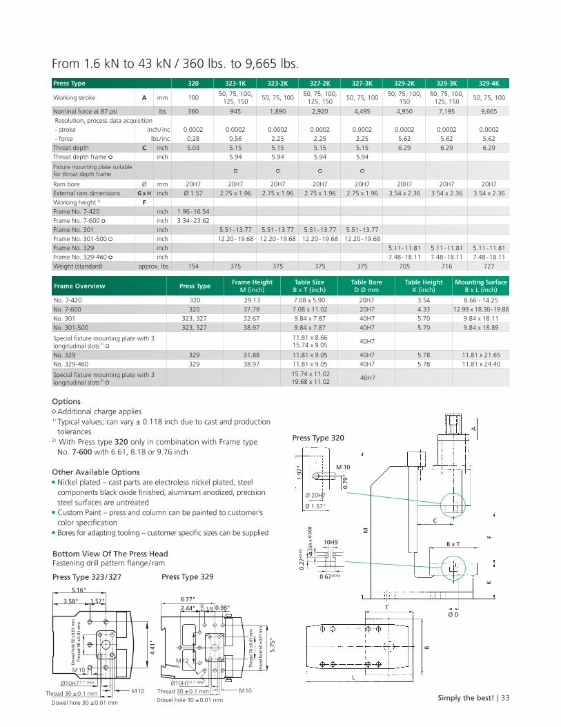
From 1.6 kN to 43 kN / 360 lbs. to 9,665 lbs.
Press Type 320 323-1K 323-2K 327-2K 327-3K 329-2K 329-3K 329-4K
Working stroke A mm 10050, 75, 100,
125, 15050, 75, 100
50, 75, 100, 125, 150
50, 75, 10050, 75, 100,
15050, 75, 100,
125, 15050, 75, 100
Nominal force at 87 psi lbs 360 945 1,890 2,920 4,495 4,950 7,195 9,665
Resolution, process data acquisition
- stroke inch / inc 0.0002 0.0002 0.0002 0.0002 0.0002 0.0002 0.0002 0.0002
- force lbs / inc 0.28 0.56 2.25 2.25 2.25 5.62 5.62 5.62
Throat depth C inch 5.03 5.15 5.15 5.15 5.15 6.29 6.29 6.29
Throat depth frame inch 5.94 5.94 5.94 5.94
Fixture mounting plate suitable for throat depth frame
Ram bore Ø mm 20H7 20H7 20H7 20H7 20H7 20H7 20H7 20H7
External ram dimensions G x H inch Ø 1.57 2.75 x 1.96 2.75 x 1.96 2.75 x 1.96 2.75 x 1.96 3.54 x 2.36 3.54 x 2.36 3.54 x 2.36
Working height 1) F
Frame No. 7-420 inch 1.96 - 16.54
Frame No. 7-600 inch 3.34 - 23.62
Frame No. 301 inch 5.51 - 13.77 5.51 - 13.77 5.51 - 13.77 5.51 - 13.77
Frame No. 301-500 inch 12.20 - 19.68 12.20 - 19.68 12.20 - 19.68 12.20 - 19.68
Frame No. 329 inch 5.11 - 11.81 5.11 - 11.81 5.11 - 11.81
Frame No. 329-460 inch 7.48 - 18.11 7.48 - 18.11 7.48 - 18.11
Weight (standard) approx. lbs 154 375 375 375 375 705 716 727
Frame Overview Press TypeFrame Height
M (inch)Table SizeB x T (inch)
Table BoreD Ø mm
Table HeightK (inch)
Mounting Surface B x L (inch)
No. 7-420 320 29.13 7.08 x 5.90 20H7 3.54 8.66 - 14.25
No. 7-600 320 37.79 7.08 x 11.02 20H7 4.33 12.99 x 18.30 - 19.88
No. 301 323, 327 32.67 9.84 x 7.87 40H7 5.70 9.84 x 18.11
No. 301-500 323, 327 38.97 9.84 x 7.87 40H7 5.70 9.84 x 18.89
longitudinal slots 2) 11.81 x 8.6615.74 x 9.05
40H7
No. 329 329 31.88 11.81 x 9.05 40H7 5.78 11.81 x 21.65
No. 329-460 329 38.97 11.81 x 9.05 40H7 5.78 11.81 x 24.40
longitudinal slots 2) 15.74 x 11.0219.68 x 11.02
40H7
Options
Additional charge applies 1) Typical values; can vary ± 0.118 inch due to cast and production
tolerances 2) With Press type 320 only in combination with Frame type
No. 7-600 with 6.61, 8.18 or 9.76 inch
Other Available Options
Nickel plated – cast parts are electroless nickel plated, steel
steel surfaces are untreated
Custom Paint – press and column can be painted to customer’s
Bottom View Of The Press Head
M
L
A
K
B
C
B x T
F
5.16"
3.58" 1.57"
4.4
1"
M 10Thread 30 ± 0.1 mm
Dowel hole 30 ± 0.01 mm
Ø10H7 X 7 deep
Do
wel h
ole
50 ±
0.0
1 m
m
M 10
Th
read
50 ±
0.0
1 m
m
5.7
5"
M 10
6.77"
2.44" 0.98"
Ø10H7 X 7 deep
Dowel hole 30 ± 0.01 mm
Thread 30 ± 0.1 mm
1.260.6
3
Th
read
50 ±
0.0
1 m
m
Do
wel h
ole
50 ±
0.0
1 m
m
Press Type 329
Ø D
Ø 1.57"
Ø 20H7
0.7
9"1.9
7" M 10
M 12
Press Type 323 / 327
10H9
0.67+0.04
9
0.2
7+
0.0
4
± 0
.008
0.3
54
T
Press Type 320