scha tschra hger t i -...
TRANSCRIPT

Scha tschra h ger tC i g u itC i atiseur
e aggregaaty aggregat
C di i at re per ar adiRefrigerad r para ar ari sエンクロージャー用クーリングユニット
3359 xxx3273 xxx3382 xxx3383 xxx
3384 xxx3385 xxx3386 xxx3387 xxx
tage I sta ati s u d Bedie u gsa eitu gAsse b y a d perati g i structi s
tice d’e p i d’i sta ati et de tagetage e bedie i gsha d eidi gtage ch ha teri gsa vis i g
Istru i i di taggi e fu i a e tI strucci es de ta e y fu ci a ie t取扱説明書


E
C te ts1 tes d cu e tati 41 1 Ass ciated d cu e ts 41 2 CE abe i g 41 3 Rete ti f d cu e ts 41 4 Sy b s used 4
2 Safety tes 4
3 Device descripti 53 1 T V tested utput easure e t
t DI E 14511 53 2 Fu cti a descripti 53.2.1 How it works. . . . . . . . . . . . . . . . . . . . . . . . . . 53.2.2 Control . . . . . . . . . . . . . . . . . . . . . . . . . . . . . . 53.2.3 Bus mode (e-Comfort controller only) . . . . . . 63.2.4 Safety devices . . . . . . . . . . . . . . . . . . . . . . . . 63.2.5 Condensation. . . . . . . . . . . . . . . . . . . . . . . . . 63.2.6 Filter mats. . . . . . . . . . . . . . . . . . . . . . . . . . . . 63.2.7 Door limit switch. . . . . . . . . . . . . . . . . . . . . . . 63.2.8 Additional interface X3. . . . . . . . . . . . . . . . . . 73 3 Pr per use 73 4 Sc pe f supp y 7
4 Asse b y a d c ecti 74 1 Ch si g the i sta ati site 74 2 tes asse b y 74.2.1 General . . . . . . . . . . . . . . . . . . . . . . . . . . . . . 74.2.2 Layout of the electronic components
in the enclosure . . . . . . . . . . . . . . . . . . . . . . . 84 3 Fitti g the c i g u it 84.3.1 Making the cut-outs . . . . . . . . . . . . . . . . . . . . 94.3.2 Top mounting of the cooling unit . . . . . . . . . . 94 4 C ecti g the c de sate discharge 94 5 tes e ectrica i sta ati 104.5.1 Connection data. . . . . . . . . . . . . . . . . . . . . . 104.5.2 Overvoltage protection and
supply line load . . . . . . . . . . . . . . . . . . . . . . 104.5.3 Three-phase devices . . . . . . . . . . . . . . . . . . 104.5.4 Door limit switch. . . . . . . . . . . . . . . . . . . . . . 114.5.5 Notes on the flicker standard. . . . . . . . . . . . 114.5.6 Potential equalisation . . . . . . . . . . . . . . . . . . 114 6 a i g the e ectrica c ecti 114.6.1 Bus connection
(only when interconnecting several units with an e-Comfort controller) . . . . . . . . 11
4.6.2 Connection X3 for serial interface . . . . . . . . 114.6.3 Installing the power supply . . . . . . . . . . . . . 134 7 Fi a isi g asse b y 154.7.1 Installing the filter media . . . . . . . . . . . . . . . 154.7.2 Fitting the cooling unit . . . . . . . . . . . . . . . . . 154.7.3 Setting the filter mat monitor . . . . . . . . . . . . 15
5 Start up 15
6 perati 166 1 C tr usi g the e C f rt c tr er 166.1.1 Properties . . . . . . . . . . . . . . . . . . . . . . . . . . 166.1.2 Eco mode . . . . . . . . . . . . . . . . . . . . . . . . . . 166.1.3 Launching test mode . . . . . . . . . . . . . . . . . 176.1.4 General information about programming . . 176.1.5 Editable parameters . . . . . . . . . . . . . . . . . . 186.1.6 Programming overview . . . . . . . . . . . . . . . . 196.1.7 Defining system messages for evaluation . 206.1.8 Setting the master/slave identifier . . . . . . . . 216.1.9 Evaluating system messages . . . . . . . . . . . 216.1.10 Resetting the e-Comfort controller . . . . . . . 23
7 I specti a d ai te a ce 237 1 C pressed air c ea i g 23
8 St rage a d disp sa 25
9 Tech ica detai s 269 1 Tech ica specificati s 269 2 Perf r a ce diagra s 299.2.1 Single-phase by output category . . . . . . . . 299.2.2 3-phase by output category . . . . . . . . . . . . 31
10 ist f spare parts 32
11 Appe dix Cut ut a d h e si es 3411 1 Di e si s f r asse b y 34
Rittal cooling unit assembly and operating instructions 3

1 tes d cu e tati
E
1 tes d cu e tatiThese assembly instructions are aimed at – tradespersons who are familiar with assembly andinstallation of the cooling unit– trained specialists who are familiar with operation
of the cooling unit
1 1 Ass ciated d cu e tsAssembly and operating instructions exist as paper documents and/or on CD-ROM for the unit types de-scribed here and are enclosed with the equipment.We cannot accept any liability for damage associat-ed with failure to observe these instructions. Where applicable, the instructions for any accessories used also apply.
1 2 CE abe i gThe declaration of conformity is supplied with the unit as a separate document.
1 3 Rete ti f d cu e tsThese instructions and all associated documents constitute an integral part of the product. They must be given to the plant operator. The operator is re-sponsible for storage of the documents so they are readily available when needed.
1 4 Sy b s used
2 Safety tesPlease observe the following general safety notes when assembling and operating the unit:– Assembly, installation and servicing may only
be performed by properly trained specialists.– Do not obstruct the air inlet and air outlet of the
cooling unit inside and outside the enclosure (see section 4.2.2).
– The heat loss of the components installed in the enclosure must not exceed the specific useful cooling power of the cooling unit.
– The cooling unit must always be transported in a horizontal position.
– Use only original spare parts and accessories.– Do not make any changes to the cooling unit other
than those described in these instructions or associated instructions.
– Risk of burns! On cooling units with automatic con-densate evaporation, the surface of the thermal element will get very hot during operation, and will remain so for some time afterwards.
– The mains connector of the cooling unit must only be connected and disconnected with the system de-energised. Connect the pre-fuse specified on the rating plate.
The bu et p i t i dicates a acti t be perf r ed
Da ger!I ediate da ger t ife a d i b!
Cauti ! P te tia threat t the pr duct a d the e vir e t
teUseful information and special features.
4 Rittal cooling unit assembly and operating instructions

3 Device descripti
E
3 Device descriptiDepending on the model chosen, your cooling unit may vary in appearance from the illustrations con-tained in these instructions. However, the functions are identical in principle.Fig. 1: Device description
ey1 Enclosure2 Air outlet holes3 Rating plate4 Louvred grille for air inlet5 Display6 X2 master-slave connection (underside of the unit)7 X1 terminal strip (underside of the unit)8 X3 optional serial interface (underside of the unit)9 Dispatch bag10 Twin-threaded bolt11 Condenser12 Condensate discharge
3 1 T V tested utput easure e t t DI E 14511
All TopTherm cooling units in the output range from 300 to 4000 W are tested to the latest EN 14511:2012-01 standard by independent test institute TÜV Nord. This means you have peace of mind about the design of the climate control solution and you can be sure you are getting the perform-ance you are paying for.
3 2 Fu cti a descriptiEnclosure cooling units are designed to dissipate heat from enclosures by cooling the air inside the enclosure and so protect the temperature-sensitive components. It is mounted on the roof of an enclo-sure.
3 2 1 H w it w r sThe cooling unit (compression refrigeration system) comprises four main components (see fig. 2): the evaporator (1), the refrigerant compressor (2), the condenser (3), and the control or expansion valve (4), which are connected by suitable pipework. This circuit is filled with a readily boiling substance, the refrigerant. The refrigerant R134a (CH2FCF3) is chlorine-free. Its Ozone Depletion Potential (ODP) is 0, making it very eco-friendly. A filter dryer (5) which is integrated into the hermetically sealed cooling cir-cuit provides effective protection against moisture, acid, dirt particles, and foreign bodies within the cooling circuit.
Fig. 2: Cooling circuit
In the evaporator coil (1), the liquid refrigerant is converted to a gaseous state. The energy needed for this purpose is taken from the enclosure air in the form of heat, which has the effect of cooling the enclosure air. In the compressor (2), the refrigerant is heavily compressed, so that it achieves a higher temperature inside the condenser (3) than the ambi-ent air. This means that excess heat may be emitted to the ambient air via the surface of the condenser, as a result of which the temperature of the refrigerant drops and it is converted back into liquid. It is re-injected into the evaporator coil via a thermostatic expansion valve (4), which causes it to cool down further, and is then once again able to absorb the energy from the enclosure air in the evaporator coil. The whole cycle begins again.
3 2 2 C trRittal enclosure cooling units are fitted with a controller for setting the functions of the cooling unit (display plus extended functions, see chapter “6 Operation”, page 16).
3
6, 7, 8
12
4
11
10
9
5
2
1
PSAH
pressureswitch
Condenser fan
Expa si va ve (4)
Temperature control
Filter dryer (5)
Internal circuit
C press r (2)
External circuit
Evaporator fan
Evap rat r c i (1)
C de ser (3)
Rittal cooling unit assembly and operating instructions 5

3 Device descripti
E
3 2 3 Bus de (e C f rt c tr er y)The serial unit interface X2 allows you to create a bus connection with up to ten cooling units using the master-slave cable (shielded, four-wire cable, Model No. 3124.100). This allows you to implement the following functions:– Parallel unit control (the cooling units in the networkcan be switched on and off simultaneously)– Parallel door status message (“door open”) – Parallel collective fault message Data is exchanged via the master-slave connection. During commissioning, assign an address to each unit that also includes the identifier “master” or “slave”.
3 2 4 Safety devices– In the cooling cycle, the cooling unit has a tested
pressure switch to EN 12 263 which is set to maxi-mum PS (permissible pressure); this operates via an automatic reset device whenever the pressure drops again.
– Temperature monitoring prevents the evaporator coil from icing over. If there is a risk of icing, the compressor switches itself off and automatically switches itself back on again at higher tempera-tures.
– The refrigerant compressor and the fans are equipped with thermal winding shields to protect against excess current and excess temperatures.
– In order to allow a reduction of pressure inside the compressor and hence a safe restart, once it has been switched off (e.g. upon reaching the set tem-perature via the door limit switch function or via de-energising), the device will switch back on with a delay of 180 seconds.
– The device has floating contacts on the connection pins (terminals 3 – 5), via which system messages from the device may be polled, e.g. using a PLC (2x normally open contacts, e-Comfort controller).
3 2 5 C de satiAt high levels of humidity and low temperatures in-side the enclosure, condensation may form on the evaporator coil.The cooling units have an automatic electrical con-densate evaporator. The thermal component used for this purpose is based on self-regulating PTC technology. Condensate arising on the evaporator coil is collected in a tank in the internal circuit of the cooling unit. When the water level rises, the water en-ters the PTC thermal component and is evaporated (through-flow heater principle). The water vapour streams out of the cooling unit with the airflow from the external fan.The PTC thermal component is permanently connected and has no switchpoint. It is protected against short-circuits with miniature fuses (F1.1, F1.2). If the fuse has tripped, any condensation is drained off via the safety overflow.
In the case of a malfunction or a failure in the thermal component, the condensation water is routed out of the unit via a drain pipe at the side or rear for safety reasons. For this purpose, a hose must be connect-ed to the condensate nozzle (see “4.4 Connecting the condensate discharge”, page 9). Condensate hoses are available as accessories (refer also to the accessories section in the Rittal Catalogue).
3 2 6 Fi ter atsThe entire cooling unit condenser is covered with a dirt-repelling, easy-to-clean RiNano coating. In many applications, therefore, the use of filter media is unnecessary, particularly with dry dusts.For dry, coarse dust and lint in the ambient air, we recommend installing an additional PU foam filter mat (available as an accessory) in the cooling unit. Depending on the incidence of dust, you will need to replace the filter mat from time to time.For air containing oil condensate, we recommend the use of metal filters (also available as an accesso-ry). These may be cleaned with suitable detergents and reused. When used in textile plants with heavy lint contamination, lint screens should be used (avail-able as an optional extra).Function of the filter mat monitor (with e-Comfort controller only):Dirt on the filter mat is automatically determined by measuring the temperature difference in the external circuit of the cooling unit. As the level of filter mat soiling increases, the temperature difference will increase. The setpoint value of the temperature difference in the external circuit adapts automatically to the relevant operating points in the performance diagrams. Hence there is no need to readjust the setpoint value for different unit operating points.
3 2 7 D r i it switchThe cooling unit may be operated with a floating door limit switch connected. The door limit switch is not included with the supply (available as an accessory, Model No. 4127.010).The door limit switch function causes the fans and the compressor in the cooling unit to be switched off after approximately 15 seconds when the enclosure door is opened (contacts 1 and 2 closed). This pre-vents the formation of condensation inside the enclo-sure while the enclosure door is open. In order to prevent damage to the unit, it is equipped with an ON delay: The evaporator fan cuts back in with a delay of approximately 15 seconds after the door has been closed, while the condenser fan and compressor switch on after approximately 3 minutes.
teNo external voltage may be applied to the door contacts (terminals 1 and 2).
6 Rittal cooling unit assembly and operating instructions

4 Asse b y a d c ecti
E
3 2 8 Additi a i terface X3An additional interface card may be connected to the 9-pole SUB-D connector X3 in order to incorpo-rate the cooling unit into higher-level monitoring systems (available as an accessory, interface card Model No. 3124.200).
3 3 Pr per useRittal enclosure cooling units were developed and designed in accordance with the state of the art and the recognised rules governing technical safety. Nevertheless, if used improperly, they may pose a threat to life and limb or cause damage to property. The unit is only intended for cooling enclosures. Any other use is deemed improper. The manufacturer will not be liable for any damages caused as a result of improper use, or for incorrect assembly, installation or use. All risk is borne solely by the user.Proper usage also includes the observation of all val-id documents and compliance with the inspection and servicing conditions.
3 4 Sc pe f supp yThe unit is supplied in a packaging unit in a fully assembled state. Please check the scope of supply for completeness.
Tab. 1: Scope of supply
4 Asse b y a d c ecti
4 1 Ch si g the i sta ati siteWhen choosing the installation site for the enclosure, please observe the following:– The site for the enclosure and the positioning of the
cooling unit must be carefully selected so as to ensure good ventilation. Depending on the siting of the unit, if several units are installed directly adjacent to one another, the distance from the wall must be at least 200 mm.
– The cooling unit must be installed and operated in a horizontal position (maximum deviation: 2°).
– The site must be free from excessive dirt and moisture.
– The ambient temperature must not exceed 55°C.– It must be possible to fit a condensate discharge
(see “4.4 Connecting the condensate discharge”, page 9).
– The mains connection data as stated on the rating plate of the unit must be guaranteed.
4 2 tes asse b y
4 2 1 Ge era– Check the packaging carefully for signs of dam-
age. Traces of oil on damaged packaging are an indication of refrigerant loss and leakages. Any packaging damage may be the cause of a subse-quent functional failure.
– The enclosure must be sealed on all sides (IP 54). Increased condensation will occur if the enclosure is not airtight.
– In order to avoid excessive condensation inside the enclosure, we recommend installing a door limit switch (e.g. 4127.010) which deactivates the cooling unit when the enclosure door is opened (see “3.2.7 Door limit switch”, page 6).
teThe electrical signals at the interface are of an extra-low voltage (not extra-low safety voltages to EN 60 335).
Qty Descripti
1 Enclosure cooling unit
11
1111
11
Dispatch bag:– Sealing plate (3273.xxx, 3383.xxx,
3384.xxx, 3385.xxx)– Sealing frame– Plug-in terminal strip– Assembly and installation instructions– Assembly, installation and operating
instructions on CD-ROM– Declaration of conformity– Safety notes
3 Blind rivet (3386.xxx, 3387.xxx)
1 Drilling template
Rittal cooling unit assembly and operating instructions 7

4 Asse b y a d c ecti
E
4 2 2 ay ut f the e ectr ic c p e tsi the e c sure
Fig. 3: Never direct the cold airflow at active components
Exercise particular caution with the airflow from the blowers of built-in electronic components (see fig. 3). Components for targeted air routing are available as accessories – please refer to the Rittal Catalogue.
Fig. 4: Targeted air routing inside the enclosure
Fig. 5: Cover bungs
4 3 Fitti g the c i g u itThe enclosure cooling unit is mounted on top of the enclosure roof:To this end, cut-outs must be made in the roof plate as per the drilling template included with the supply.
Cauti !Ris f c de sati !Whe arra gi g the c p e ts i side the e c sure p ease e sure that the c d airf w fr the c i g u it is t directed at active c p e ts P ease a s e sure that the c d airf w is t directed at the war exhaust airf w fr active c p e ts such as c verters This ay ead t a air sh rt circuit a d theref re preve t adequate c i ate c tr r ay eve cause the c i g u it’s i ter a safety devices t cease c i g perati
teWhen using an air duct system, care must be taken to ensure that it is laid straight and without kinks wherever possible. This mini-mises the resistance to the cold airflow.It is important to ensure even air circulation inside the enclosure. Under no circum-stances should air inlet and outlet openings be obstructed, otherwise the cooling performance of the unit will be reduced. Ensure a suitable distance from electronic components and other installed enclosures so that the required air circulation is not obstructed and prevented.One cold air outlet from the cooling unit must be kept open at all times when operating with the air duct, to prevent the accumulation of cold air inside the unit.
teWhen using the cover bungs, only a maximum of 1 or 2 cold air outlet openings may be sealed, depending on the unit type.
tePre-configured, reinforced roof plates with cut-outs to match your enclosure are available as accessories; refer to the Rittal Catalogue.
3273.xxx3383.xxx3384.xxx3385.xxx
3359.xxx3382.xxx3386.xxx3387.xxx
max. 2x max. 1x
8 Rittal cooling unit assembly and operating instructions

4 Asse b y a d c ecti
E
4 3 1 a i g the cut utsAffix the supplied drilling template to the roof of the enclosure using adhesive tape.
There are dimensioning lines on the drilling template to suit the installation type for your cooling unit.
Make the cut-outs including the line width as per the drilling template. Deburr the cut-outs.
4 3 2 T p u ti g f the c i g u itAffix the supplied sealing frame onto the cut out roof plate.
Fig. 6: Sealing frame on roof plate
Affix the supplied sealing plate to the bottom of the plastic base of the cooling unit (3273.xxx, 3383.xxx, 3384.xxx, 3385.xxx).
Fig. 7: Sealing plate underneath the plastic base of the cooling unit
Mount the cooling unit on the enclosure roof.Screw the supplied twin-threaded bolts into the core holes in the plastic base on the underside of the cooling unit with a maximum of 5 Nm.Secure the unit using the supplied washers and nuts.
Fig. 8: Roof plate reinforcement for the TS 8 enclosure
Access ries f r r f p ate rei f rce e t with TSTS roof platesQuick-change framePunched railU nutFastening bracketThreaded block(refer also to Accessories in the Rittal Catalogue)
4 4 C ecti g the c de sate dischargeA condensate discharge hose (Ø 1/2˝) may be fitted to the cooling unit.The condensate discharge– must be laid with a suitable and constant gradient
(no siphoning)– must be laid without kinks– must not have a reduced cross-section if extendedThe condensate hose is available as an accessory (refer also to Accessories in the Rittal Catalogue).
Fig. 9: Connecting the condensate discharge
Connect a suitable hose to one of the two condensate nozzles and secure using a hose clip.The condensate nozzle that is not required should be sealed.Lay the condensate hose, e.g. into a drain.
Ris f i ury!Carefu y deburr a cut uts t preve t i uries caused by sharp edges
teIn order to achieve a permanent seal be-tween the cooling unit and the enclosure, the mounting surface should be reinforced or supported if necessary. This is particu-larly applicable with large roof areas.
Rittal cooling unit assembly and operating instructions 9

4 Asse b y a d c ecti
E
Fig. 10: Laying the condensate discharge
4 5 tes e ectrica i sta atiWhen performing the electrical installation, it is im-portant to observe all valid national and regional reg-ulations as well as the provisions of the responsible power supply company. The electrical installation may only be carried out by a qualified electrician who is responsible for compliance with the applica-ble standards and regulations.
4 5 1 C ecti data– The connected voltage and frequency must
correspond to the values stated on the rating plate.– The cooling unit must be connected to the mains
via an all-pin isolating device, which ensures at least 3 mm contact opening when switched off.
– No additional temperature control may be con-nected upstream of the unit at the supply end.
– Install the pre-fuse specified on the rating plate to protect the cable and equipment from short-circuits.
– The mains connection must ensure low-noise potential equalisation.
4 5 2 verv tage pr tecti a d supp y i e ad
– The unit does not have its own overvoltage protec-tion. Measures must be taken by the operator at the supply end to ensure effective lightning and overvoltage protection. The mains voltage must not exceed a tolerance of ±10%.
– In accordance with IEC 61 000-3-11, the unit is intended solely for use at sites with a continuous current-carrying capacity (incoming mains power supply) of more than 100 A per phase and with a supply voltage of 400/230 V. If necessary, the power supply company must be consulted to en-sure that the continuous current-carrying capacity at the point of connection to the public grid is sufficient for connection of such a unit.
– The fans and compressors in single- and three-phase units are intrinsically safe (thermal winding protection). The same also applies to all transform-er versions and to special-voltage units which are likewise equipped with a transformer.
– Install the slow pre-fuse specified on the rating plate (miniature circuit-breaker with appropriate characteristic – e.g. “K” characteristic – or gG standard type slow fuse, circuit-breaker for plant or transformer protection) to protect the cable and equipment from short-circuits. Select a suitable circuit-breaker in accordance with the information specified on the rating plate: Set it to the minimum specified value. This will achieve the best short-circuit protection for cables and equipment. Example: Specified setting range 6.3 – 10 A; set to 6.3 A.
4 5 3 Three phase devices– The electrical connection for devices in the three-
phase version MUST be made with a clockwise rotating field.
– The three-phase version must be connected to a TN network with star earthing via a circuit-breaker for plant protection (current setting as per the rat-ing plate). Three-phase units with special voltages must be protected with a circuit-breaker for trans-former protection (category AC-3) as per the rating plate.
– Units designed for three phase 400/460 V feature additional monitoring of the rotary field or the ab-sence of a phase. If the rotary field is incorrect or a phase is absent, the unit will not run.
1/2˝
10 Rittal cooling unit assembly and operating instructions

4 Asse b y a d c ecti
E
4 5 4 D r i it switch– Each door limit switch must only be assigned toone cooling unit.– Several door limit switches may be connected in
parallel to one cooling unit.– The minimum cross-section for the connection
cable is 0.3 mm2 for a cable length of 2 m.We recommend the use of a shielded cable.
– The line resistance to the door limit switch must not exceed a maximum of 50 Ω.
– The door limit switch only supports a floating connection; no external voltages.
– The contact of the door limit switch must be closed when the door is open.
The safety extra-low voltage for the door limit switch is provided by the internal power pack: Current approx. 30 mA DC.
Connect the door limit switch to terminals 1 and 2 of the connector.
4 5 5 tes the f ic er sta dardThe flicker limits specified in standard EN 61 000-3-3 or -3-11 are adhered to, provided the supply impedance is less than approx. 1.5 Ω.Where necessary, the unit operator should measure the connected impedance or consult the responsible power supply company. If there is no way of influenc-ing the supply impedance and sensitive installed components (e.g. BUS) are subjected to interfer-ence, a line reactor or starting-current limiting device should be connected upstream of the cooling unit to restrict the startup current of the cooling unit.
4 5 6 P te tia equa isatiIf, for EMC reasons, the unit is to be integrated into the customer’s existing potential equalisation sys-tem, a conductor with a larger nominal cross-section can be connected to the potential equalisation connection point (attachment points) on the roof-mounted cooling units. According to the standard, the PE conductor in the mains connection cable is not classified as an equipotential bonding conductor.
4 6 a i g the e ectrica c ecti
4 6 1 Bus c ecti ( y whe i terc ecti g severa u its with a C f rt c tr er)
When using several cooling units, the serial device interface X2 can be used to connect up to ten cool-ing units with the bus cable (Model No. 3124.100).
When interconnecting, please note the following:– De-energise the cooling units to be connected– Ensure proper electrical insulation– Make sure the cables are not laid in parallel to
power lines– Make sure that the lines are short
4 6 2 C ecti X3 f r seria i terfaceThe interface card (Model No. 3124.200) may be connected to X3. This is used to evaluate system messages in a PLC, for remotely setting parameters and monitoring, or for integration into the facility management system.
teThe electrical signals at the X2 interface are of an extra-low voltage (not extra-low safety voltages in accordance with EN 60 335-1).
Cauti !With the ast s ave u it i the gr up d
t u der a y circu sta ces c ect the re ai i g s c et f the Y cab e 3124 100 i t i terface X3 f the c i g u it!
Rittal cooling unit assembly and operating instructions 11

4 Asse b y a d c ecti
E
Fig. 11: Connection example: Master-slave operation
ey1 Serial interface (Model No. 3124.200)2 Serial interface cable3 Master-slave bus cable (Model No. 3124.100)RTT Rittal TopTherm cooling units X1 Supply connection/door limit switch/alarms
X2 Master/slave connection Sub-D, 9-poleX3 Serial interface Sub-D, 9-poleSt. Sub-D connector, 9-poleBu. Sub-D jack, 9-poleAdr. Address
Fig. 12: Connection example: Door limit switch and master-slave operation
ey1 Master cooling unit2 Slave cooling units3 2-door enclosure with two door limit switches4 Enclosure with door limit switch
X2
CMC
I/O unit
RTTMaster
Adr.: 09
X1
X2 X3
X1
X2 X3
X1
X2 X3
X1
X2 X3
X2 X3 X2X2
X2 X2
X2
X2
St. St. St.Bu.
St.Bu.
X2
Adr.: 11 Adr.: 12RTTSlave
RTTSlave
Adr.: 19RTTSlave
St.Bu.
St.
Bu.
3
2
1
X10 L1 L2N PE 1 2 3 4 5
1
X10 X10 X10 X10 X10
X2 X2 X2 X2 X2 X2
X2
L1 PE 1 2 3 4 5 L1 L2N PE 1 2 3 4 5L2 L3 L1 PE 1 2 3 4 5L2 L3 L1 PE 1 2 3 4 5L2 L3 L1 PE 1 2 3 4 5L2 L3
L1L2 N
PE
12
34
5
X10
2 3 4 5 6
1Adr.: 06 Adr.: 11 Adr.: 12 Adr.: 13 Adr.: 14 Adr.: 15
2 2 2 2 2
3 4 4 3 2
Adr.: 16
12 Rittal cooling unit assembly and operating instructions

4 Asse b y a d c ecti
E
4 6 3 I sta i g the p wer supp yComplete the electrical installation as per the wiring plan inside the cooling unit underneath the cable shaft cover (see fig. 29 on page 24, marked with an arrow).
If you would like the system messages from the cooling unit to be evaluated via the system mes-sage relay, you should also connect a suitable low-voltage cable to connection pins 3 – 5.
Fig. 13: Electrical wiring plan no. 1
Fig. 14: Electrical wiring plan no. 2
Mains S1
A2
Power
E1F11
Term
F2
C1
F2
PE
T1
M4M2M1
X1
NTC E blue
NTC I red
F12
1~M M
M4M2M1
1~
5
1
S1
31 2321
321L1 54NL2 PE
321 321 321
4
2
2
B2
B1
P
X2 X3
K2 K1
B5
B4
B3
2
2
2
NTC C white
NTC A yellow
Level green
12
MS1 Serial
3 8
2L N
A1
Kx
1312
1110
14
3359.5xx/.6xx, 3382.5xx/.6xx
PEPE
PE
2221
3383.5xx/.6xx, 3384.5xx/.6xx, 3385.5xx/.6xx
Power
F3
Kx
F2
A1
M4M2M1
NTC E blueNL
1321 2321
321 321 321
2 B1
2
4Term
Mains S1
A2
E1
C1
PE
T1
X1
1~M M
M4M2M1
1~
6
321L1 54NL2 PE
22
P
21
M
M3
1~
1412 13
M1C1.1A3
5
4
LNPE
C1.2
PE
X2 X3
3 8
F11 F12
K2 K1
NTC I redSerial
NTC C white
NTC A yellow
Level green
2
2
2
B2
B3
B4
B5
21
F2
10 11
F3
2
1
MS1
y f r 3383 xxx a d 3384 xxx y f r 3385 xxx
Rittal cooling unit assembly and operating instructions 13

4 Asse b y a d c ecti
E
Fig. 15: Electrical wiring plan no. 3
eyA1 Power PCBA2 Display terminalA3 Starter relay and RC elementB1 Temperature sensor, internal temperatureB2 Icing hazard temperature sensorB3 Condenser temperature sensorB4 Ambient temperature sensorB5 Condensate warning sensor (optional)C1 Start-up capacitor (3383.xxx/3384.xxx)C1.1 Operating capacitor (3385.xxx)C1.2 Start-up capacitor (3385.xxx)E1 Condensate evaporatorF2 PSAH pressure switch F3 Compressor thermal contactF11/F12 Miniature fuses, condensate evaporatorK1 Relay collective fault 1K2 Relay collective fault 2M1 CompressorM2 Condenser fanM3 Condenser fan (optional)
(3383.xxx to 3387.xxx)M4 Evaporator fanS1 Door limit switch
(without door limit switch: terminal 1, 2 open)T1 Transformer (optional)X1 Main terminal stripX2 Master/slave connectionX3 Optional interface
Tab. 2: Contact data
Mains S1
A2
Power
E1F11
Term
F2
Kx
PE
A1
M4M2M1
X1
NTC E blue
NTC I red
F12
3~
M M
M4M2M1
3~
6
1
321 4
4
2
2
B2
B1
22
P
21
83
B5
B4
B3
2
2
2
NTC C white
NTC A yellow
Level green
MS1 Serial
M
M3
3~
X2 X3
K2 K1S1
F3 F2 F4 F5321 4 321 1321 4 321 2
321 4
32 143 2 1 2
L3L2L1 5PE
TR S
U V
W
PEPE
PE
3386.54x/.64x, 3387.54x/.64x
teFor technical data, refer to the rating plate.
ACc s f 1
DCR 20 s
I max. = 2 AU max. = 250 V
I min. = 100 mAU max. = 200 VU min. = 18 VI max. = 2 A
14 Rittal cooling unit assembly and operating instructions

5 Start up
E
4 7 Fi a isi g asse b y4 7 1 I sta i g the fi ter ediaThe entire cooling unit condenser is covered with a dirt-repelling, easy-to-clean RiNano coating. In many applications, therefore, the use of filter media is unnecessary, particularly with dry dusts.For dry, coarse dust and lint in the ambient air, we recommend installing an additional PU foam filter mat (available as an accessory) in the cooling unit. For air containing oil condensate, we recommend the use of metal filters (also available as an accesso-ry). When used in textile plants with heavy lint con-tamination, lint screens should be used (available as an optional extra).
Pull the louvred air inlet grille off the enclosure.Secure the filter mat in front of the condenser using the supplied blind rivets.Then push the louvred grille back onto the enclosure.
4 7 2 Fitti g the c i g u itConnect the connector to the rear of the display.Place the louvred grille onto the unit at the front, and press it down until you hear it snap into place.
Fig. 16: Connect the display and attach the louvred grille
4 7 3 Setti g the fi ter at it r Function of the filter mat monitor:Dirt on the filter mat is automatically detected by measuring the temperature difference in the external circuit of the cooling unit (see “6.1.6 Programming overview”, page 19). As the level of filter mat soiling increases, the temperature difference will increase. The setpoint value of the temperature difference in the external circuit adapts automatically to the rele-vant operating points in the performance diagrams. Hence there is no need to readjust the setpoint value for different unit operating points.
5 Start up
Once all the assembly and installation work is complete, switch on the power supply to the cooling unit.
The cooling unit starts running:– The software version of the controller first appears
for approx. 2 seconds, then “ECO” to show Eco mode is enabled. The internal enclosure tempera-ture will then appear in the 7-segment display.
You can now make your individual settings on the unit e.g. set the temperature or assign the network identifier etc. (refer to chapter “6 Operation”).
Cauti ! Ris f da age!The i ust be c ected i the c press r i rder t e sure effective ubricati a d c i gD t perate the c i g u it f r at east 30 i utes after asse b i g the equip e t
Rittal cooling unit assembly and operating instructions 15

6 perati
E
6 peratiYou can operate the cooling unit using the controller on the front of the device (fig. 1, no. 5, page 5).6 1 C tr usi g the e C f rt c tr erFor unit types xxxx.500/.510/.540 and xxxx.600/.610/.640.
Fig. 17: e-Comfort controller
ey1 Programming button, also display of the set
temperature unit (degrees Celsius)2 Set button3 Programming button, also display of the set
temperature unit (degrees Fahrenheit)4 7-segment display
6 1 1 Pr perties– Rated operating voltage:
– 115 V or– 230 V or– 400 V, 2-phase or– 400/460 V, 3-phase
– Integral start-up delay and door limit switch function.
– Protective function to prevent icing.– Monitoring of all motors
(compressor, condenser fan, evaporator fan).– Phase monitoring for three-phase units.– Master-slave function with a maximum of ten units.
One device functions as a master unit. Once the set temperature is reached by one of the connect-ed slave devices or in the event of the door limit switch function, the affected slave unit will report to the master unit that switches all the other cooling units on or off as required.
– Switching hysteresis: adjustable within the range 2 – 10 K, preset to 5 K.
– Visualisation of the current internal enclosure tem-perature and all error messages in the 7-segment display.
– Using an interface card (Model No. 3124.100), the unit may be incorporated into higher-level remote monitoring systems such as the Rittal Computer Multi Control CMC.
The cooling unit operates automatically, i.e. after switching on the power supply, the evaporator fan (see fig. 2, page 5) will run and circulate the internal enclosure air. The compressor and condenser fan are regulated by the e-Comfort controller.The e-Comfort controller has a 7-segment display (fig. 17, no. 4). After switching on the power supply, the current software version initially appears on this display for approx. 2 seconds together with the symbol to show Eco mode is enabled, followed by a preset option (e.g. t10) or the temperature. In regular operation, the display shows both the temperature (in degrees Celsius or Fahrenheit – users may switch between the two) and any error messages. The current internal enclosure temperature is usually displayed permanently. In the event of an error mes-sage, this alternates with the temperature display.The unit is programmed using buttons 1 – 3 (fig. 17). The relevant parameters also appear in the display.
6 1 2 Ec deAll Rittal TopTherm cooling units with e-Comfort controller from firmware 3.2 have the energy-saving eco mode, which is enabled in the delivered state.The eco mode is used to save energy in the heat exchanger if there is no thermal load, or there is a low thermal load in the enclosure (e.g. standby opera-tion, no production or weekend). During this process the evaporator fan in the internal circuit is switched off as appropriate if the actual in-ternal enclosure temperature drops to 10 K below the specified setpoint temperature. To ensure the internal temperature is reliably measured during this process, the fan starts cyclically for 30 sec. every 10 minutes (see fig. 18). If the internal temperature drops to a range 5 K below the setpoint set again, the fan switches back to continuous operation. If required, eco mode can be disabled on the control display. For this purpose switch the parameter from 1 to 0 in the programming level (see tab. 3, page 18). The fan then runs continuously.
Fig. 18: Eco mode
1 2
4 3
ONStatus internal fan
Internal temperature
Time
Setpoint -5°CSetpoint -10°C
OFF
10 min.
30 sec.
10 min.
16 Rittal cooling unit assembly and operating instructions

6 perati
E
6 1 3 au chi g test deThe e-Comfort controller is equipped with a test func-tion whereby the cooling unit commences cooling operation independently of the set temperature or door limit switch function.Simultaneously press buttons 1 and 2 (fig. 17) for at least five seconds.
The cooling unit will commence operation.Test mode is completed after approximately 5 min-utes. The unit switches off and changes to normal operation.
6 1 4 Ge era i f r ati ab ut pr gra i gUsing buttons 1, 2 and 3 (fig. 17) you can change 24 parameters within the preset ranges (min. value – max. value).Tables 3 and 4 show the parameters which can be altered. Fig. 20 on page 19 shows which buttons must be pressed.
In principle, the programming is identical for all edit-able parameters.To enter programming mode:
Press button 2 (“Set”) for approx. 5 seconds.The controller is now in programming mode. While in programming mode, if you do not press any buttons for approx. 30 seconds, the display will first flash, then the controller will switch back to normal display mode. “Esc” in the display indicates that any changes made have not been saved.
Press the programming buttons ▲ (°C) or ▼ (°F) to switch between the editable parameters (see tables 3 and 4).Press button 2 (“Set”) to select the displayed parameter for editing.
The current value of this parameter is displayed.Press one of the programming buttons ▲ (°C) or ▼ (°F).
“Cod” will appear in the display. In order to be able to change a value, you must enter the authorisation code “22”.
Keep the ▲ programming button (°C) held down until “22” appears.Press button 2 (“Set”) to confirm the code.
You can now alter the parameter within the preset limits.
Press one of the programming buttons ▲ (°C) or ▼ (°F) until the required value appears.Press button 2 (“Set”) to confirm the change.
You can now alter other parameters in the same way. There is no need to re-enter the authorisation code “22”.
To exit programming mode, press button 2 (“Set”) again for approximately five seconds.
“Acc” will appear in the display to indicate that the changes have been saved. The display then switches back to regular operation (internal enclosure temperature).You can also program the e-Comfort controller using a diagnosis software package (Model No. 3159.100), which is supplied with a connection cable to the PC. The cable connector on the rear of the e-Comfort controller display serves as an interface.
te switchi g hysteresisWith a low hysteresis and short switching cycles, there is a risk that cooling may not be adequate or that only partial sections of the enclosure are cooled. If the cooling unit is oversized and compressor run times are too long < 1 minute, the switching hystere-sis to protect the cooling unit is automatical-ly increased.
te te perature setti gsWith the e-Comfort controller, the tempera-ture is preset at the factory to +35°C. In order to save energy, and due to the risk of increased condensation, do not set the temperature lower than that actually necessary.
te usefu c i g p werInteractive performance diagrams for calculating the useful cooling power may be found at www.rittal.com.
Rittal cooling unit assembly and operating instructions 17

6 perati
E
6 1 5 Editab e para etersSee also fig. 20 on page 19.Tab. 3: Editable parameters
Pr gr eve
Disp ay scree
Para eter i va ue
ax va ue
Fact ry setti g
Descripti
1 St Internal enclosure temperature set-point Ti
20 55 35 The internal enclosure temperature setting is preset at the factory to 35°C and may be altered within a range of 20 – 55°C.
2 Fi Filter mat monitoring
10 60 99 (= off)
To enable filter mat monitoring, the display should be set to a minimum of 10 K above the tempera-ture difference shown in programming mode “Fi”; filter mat monitoring is disabled at the factory (99 = off).
3 Ad Master-slave identifier
0 19 0 See “6.1.8 Setting the master/slave identifier”, page 21.
4 CF Switch between°C/°F
0 1 0 The temperature display can be switched be-tween °C (0) and °F (1). The LED displays the current unit of temperature.
5 H1 Setting forswitching difference (hysteresis)
2 10 5 The cooling unit is preset in the factory to a switching hysteresis of 5 K. This parameter should only be changed in consultation with us. Please contact us for advice.
6 H2 Differential for error message A2
3 15 5 If the internal enclosure temperature exceeds the set value by more than 5 K, then error message A2 (internal enclosure temperature too high) appears on the display terminal. If necessary, the differential may be altered here within the range of 3 – 15 K.
26 ECO Eco-mode operation
0 1 1 Eco mode OFF: 0 / Eco mode ON: 1
27 PSO Changing the authorisation code
0 15 0 This parameter allows you to change the “22” authorisation code (factory setting). The new code results from the sum of 22 + PSO.
18 Rittal cooling unit assembly and operating instructions

6 perati
E
6 1 6 Pr gra i g verviewFig. 19: Programming overview
= 5
sec
.
= 5
sec
.
= 5
sec
.
= 5
sec
.
Rittal cooling unit assembly and operating instructions 19

6 perati
E
6 1 7 Defi i g syste essagesf r eva uatiSystem messages are shown on the display screen of the e-Comfort controller via the displays A1 to A20 and E0.
A more detailed explanation of the system messages may be found in section “6.1.9 Evaluating system messages”, page 21. See also fig. 19 on page 19.
Tab. 4: System messages that can be evaluated via relays
The system messages A1 – A19 may also be evalu-ated via two floating system message relays. In this way, one of the two system message relays may be allocated to each system message.System message relays with normally open contact, see wiring diagrams at section “4.6.3 Installing the power supply”, page 13:– Terminal 3: NO (normally open, relay 2)– Terminal 4: C (connection of the supply voltage to
the system message relay)– Terminal 5: NO (normally open, relay 1)
The definition NO refers to the de-energised state. As soon as power is applied to the cooling unit, both system message relays (relay 1 and 2) energise. This is the normal operating state of the cooling unit. As soon as a system message occurs or the power supply is interrupted, the corresponding relay will drop out and open the contact.
The RiDiag II software (available as an accessory, Model No. 3159.100) allows you to invert the system message relay circuit. In the normal operating state the two relays will then drop out. If a system message occurs, the relevant relay will energise and the contact will close.
Program system messages with the value0: System message is not sent to the system
message relay, but merely appears in the display
1: System message is evaluated by relay 12: System message is evaluated by relay 2
Pr gr eve
Disp ay scree
i va ue
ax va ue
Fact ry setti g
Type r cati f fau t
7 A1 0 2 0 Enclosure door open
8 A2 0 2 0 Internal temperature of enclosure too high
9 A3 0 2 0 Filter monitoring
10 A4 0 2 0 Ambient temperature too high/low
11 A5 0 2 0 Icing hazard
12 A6 0 2 1 PSAH pressure switch
13 A7 0 2 2 Evaporator coil
14 A8 0 2 1 Condensate warning
15 A9 0 2 1 Condenser fan blocked or defective
16 A10 0 2 1 Evaporator fan blocked or defective
17 A11 0 2 2 Compressor
18 A12 0 2 1 Condenser
19 A13 0 2 1 Ambient temperature sensor
20 A14 0 2 1 Icing temperature sensor
21 A15 0 2 1 Condensate warning temperature sensor
22 A16 0 2 1 Internal temperature sensor
23 A17 0 2 1 Phase monitoring
24 A18 0 2 0 EPROM
25 A19 0 2 0 LAN/Master-Slave
teThis setting can only be made using the RiDiag II software.
20 Rittal cooling unit assembly and operating instructions

6 perati
E
6 1 8 Setti g the aster s ave ide tifierWhen several cooling units are connected together (maximum ten), one of the cooling units must be defined as the “master” and the others as “slaves”. For this purpose, assign a corresponding identifier (address) to each cooling unit which will enable the cooling unit to be identified in the network.If one of the slave units reaches the set temperature or if the door limit switch function is activated, the affected slave unit will report to the master unit, which then deactivates all the other cooling units.On the aster c i g u it (00 = factory setting), set the number of slave units present in the network:01: Master with 1 slave cooling unit02: Master with 2 slave cooling units03: Master with 3 slave cooling units04: Master with 4 slave cooling units05: Master with 5 slave cooling units06: Master with 6 slave cooling units07: Master with 7 slave cooling units08: Master with 8 slave cooling units09: Master with 9 slave cooling units
On the s ave c i g u it (00 = factory setting), set its own address:11: Slave cooling unit no. 112: Slave cooling unit no. 213: Slave cooling unit no. 314: Slave cooling unit no. 415: Slave cooling unit no. 516: Slave cooling unit no. 617: Slave cooling unit no. 718: Slave cooling unit no. 819: Slave cooling unit no. 9
Fig. 20: Master/slave connection (example)
For further connection examples, see “4.6.1 Bus connection (only when interconnecting several units with a Comfort controller)”, page 11.For details of how to set the identifier, see “6.1.5 Editable parameters”, page 18 or “6.1.6 Programming overview”, page 19, parameter “Ad”.
6 1 9 Eva uati g syste essagesIn the e-Comfort controller, system messages are indicated by a number in the display.Following the appearance of messages A03, A06 and A07 and after rectifying their cause, you will need to reset the e-Comfort controller (see “6.1.10 Resetting the e-Comfort controller”, page 23).
tes– Only one unit may be configured as
master, and its identifier must match the number of connected slave units.
– The slave units must have different identifiers.
– The identifiers must be numbered in ascending order without any gaps.
Master 02
Slave 11
Slave 12
Rittal cooling unit assembly and operating instructions 21

6 perati
E
Tab. 5: Troubleshooting with the e-Comfort controller
Disp ay scree
Syste essage P ssib e cause easures t rectify the fau t
A01 Enclosure door open Door open or door limit switch incorrectly positioned
Close door, position door limit switch correctly, check connection if necessary
A02 Internal temperature of enclosure too high
Cooling capacity inadequate/unit undersized. Error as a consequence of messages A03 to A17.
Check cooling capacity
A03 Filter monitoring Filter mat soiled Clean or replace;reset the e-Comfort controller
A04 Ambient temperature too high/low
Ambient temperature outside permissible operating range (+10°C to +60°C)
Raise or lower the ambient temperature (e.g. heat or ventilate the room)
A05 Icing hazard Operational display in case of icing hazard. Evaporator coil fan may be mechanically blocked, defective, or cold air outlet obstructed.
Set the enclosure interior temperature to a higher value. Check the evaporator fan; release or exchange if necessary.
A06 PSAH pressure switch Ambient temperature too high Lower the ambient temperature;reset the e-Comfort controller
Condenser soiled Clean the condenser;reset the e-Comfort controller
Filter mat soiled Clean or replace;reset the e-Comfort controller
Condenser fan defective Replace;reset the e-Comfort controller
E-valve defective Repair by refrigeration engineer;reset the e-Comfort controller
PSAH pressure switch defective Refrigeration engineer to exchangereset the e-Comfort controller
A07 Evaporator coil Lack of refrigerant; Sensor in front of or behind condenser defective
Repair by refrigeration engineer;reset the e-Comfort controller
A08 Condensate warning Condensate discharge kinked or blocked Check condensate drainage; correct any kinks or blockages in the hose
Only for units with optional condensate evaporation
Check the evaporation unit, replace if necessary
A09 Condenser fan Blocked or defective Clear the blockage; replace if necessary
A10 Evaporator fan Blocked or defective Clear the blockage; replace if necessary
A11 Compressor Compressor overloaded (internal winding protection)
No action required; Unit switches on again independently
Defective (check by measuring the winding resistance)
Replace by a refrigeration engineer
A12 Condenser temperature sensor
Open or short-circuit Replace
A13 Ambient temperature sensor
Open or short-circuit Replace
A14 Icing temperature sensor Open or short-circuit Replace
A15 Condensate warning temperature sensor
Open or short-circuit Replace
A16 Internal temperature sensor Open or short-circuit Replace
A17 Phase monitoring For three-phase devices only: Incorrect rotary field/phase absent
Swap two phases
A18 EPROM error New board installed incorrectly Software update needed (only following board installation with more recent software): Enter the programming level with Code 22; press button 1 and confirm with “Set” until “Acc” appears. Next, disconnect the unit from the mains and reconnect.
A19 LAN/Master-Slave Master and slave not connected Check setting and/or cable
A20 Voltage drop Error display not shown Event is stored in the log file
E0 Display message Connection problem between the display and the controller board
Reset: Switch power supply off, then switch on again after approx. 2 sec.
Cable defective; connection loose Replace the boards
OL Overload Ambient parameters or heat loss outside the applicable limits
b07 Leak in the cooling circuit Sensor B3 and B4 swapped over Swap the sensors
rSt Reset Manual device reset required, see “6.1.10 Resetting the e-Comfort controller”, page 23.
22 Rittal cooling unit assembly and operating instructions

7 I specti a d ai te a ce
E
6 1 10 Resetti g the e C f rt c tr erAfter the occurrence of faults A03, A06 and A07, you will need to reset the e-Comfort controller.Press buttons 1 (▲) and 3 (▼) (fig. 17) simultane-ously for 5 seconds.
The system messages disappear and the tempera-ture display is shown.
7 I specti a d ai te a ce
The cooling circuit is designed in the form of a main-tenance-free, hermetically sealed system. The cool-ing unit is filled with the required quantity of refriger-ant at the factory, checked for leaks, and subjected to a functional test run.The installed maintenance-free fans are mounted on ball bearings, protected against moisture and dust, and fitted with a temperature monitor. The life expectancy is at least 30,000 operating hours. The cooling unit is thus largely maintenance-free. All that may be required from time to time is to clean the components of the external air circuit using a vacu-um cleaner or compressed air if they become visibly dirty. Any stubborn, oily stains may be removed us-ing a non-flammable detergent, such as degreaser.Maintenance interval: 2,000 operating hours. Depending on the level of contamination in the ambient air, the maintenance interval may be reduced to suit the air pollution intensity.
Sequence of maintenance measures:– Check the level of dirt.– Filter soiling? Replace the filter if necessary.– Cooling membranes soiled? Clean if necessary.– Activate test mode; cooling function OK?– Check noise generation of compressor and fans.
7 1 C pressed air c ea i g
Fig. 21: Disconnect the mains plug
Fig. 22: Release the louvred grille
Fig. 23: Remove the louvred grille
Ris f e ectric sh c !The u it is ive Switch ff the p wer supp y bef re
pe i g a d ta e suitab e precauti s agai st it bei g accide ta y switched bac
Cauti !Ris f fire!
ever use f a ab e iquids f r c ea i g
Rittal cooling unit assembly and operating instructions 23

7 I specti a d ai te a ce
E
Fig. 24: Disconnect the connector from the display
Fig. 25: Disconnect the earthing cable
Fig. 26: Remove the assembly screws from the cover (loosen four screws)
Fig. 27: Remove the cover
Fig. 28: Cooling unit without cover (front view)
Fig. 29: Cooling unit without cover (rear view)
24 Rittal cooling unit assembly and operating instructions

8 St rage a d disp sa
E
Fig. 30: Clean the heat exchanger coil and compressorchamber using compressed air
Fig. 31: Fit the louvred grille
8 St rage a d disp sa
During storage, the cooling unit must stand upright.The closed cooling cycle contains refrigerant and oil, which must be properly disposed of for the protec-tion of the environment. Facilities for disposal are available at the Rittal plant. Please contact us for advice.
Cauti ! Ris f da age!The c i g u it ust t be sub ected t te peratures ab ve 70 C duri g st rage
Rittal cooling unit assembly and operating instructions 25

9 Tech ica detai s
E
9 Tech ica detai s9 1 Tech ica specificati s
Fig. 32: Rating plate (technical data)
– Observe the mains connection data (voltage and frequency) as per the rating plate.
– Observe the pre-fuse as per the specifications on the rating plate.
U it de
e C f rt c tr er RA 7035 – 3382 500 3382 510 3359 500 3359 510 3359 540 3383 500 3383 510 3383 540
e C f rt c tr er Stai ess stee c ver – 3382 600 3382 610 3359 600 3359 610 3359 640 3383 600 3383 610 3383 640
Rated voltage VHz
230, 1~, 50/60
115, 1~, 50/60
230, 1~, 50/60
115, 1~, 50/60
400, 2~, 50/60
230, 1~, 50/60
115, 1~, 50/60
400, 2~, 50/60
Rated current A 2.3/2.6 4.1/5.4 2.8/3.7 5.6/7.4 1.6/2.1 2.9/3.9 6.2/8.4 1.7/2.2
Start-up current A 9.1/18.8 18.2/15.9 9.2/9.0 18.4/18.0 5.4/5.2 8.8/10.1 14.4/15.8 4.6/5.7
Pre-fuse T A 10.0 – 10.0 – – 10.0 – –
Motor circuit-breaker – – – – – – – – –
Transformer circuit-breaker – – 6.3 to 1.0 – 11 to 16 6.3 to 1.0 – 11 to 16 6.3 to 10
Miniature circuit-breaker or gG slow fuse (T) – � – � – – � – –
Total cooling output Pc L 35 L 35to DIN EN 14511 L 35 L 50
kWkW
0.55/0.620.42/0.48
0.55/0.620.42/0.58
0.77/0.790.52/0.47
0.77/0.790.52/0.47
0.77/0.790.52/0.47
1.00/1.090.71/0.81
1.00/1.090.71/0.81
1.00/1.090.71/0.81
Sensible cooling output Ps
to DIN EN 14511 L 35 L 35 kW 0.37/0.42 0.37/0.42 0.76/0.78 0.76/0.78 0.76/0.78 1.00/1.09 1.00/1.09 1.00/1.09
Power consumption Pel L 35 L 35to DIN EN 14511 L 35 L 50
kWkW
0.27/0.310.31/0.37
0.27/0.310.31/0.37
0.33/0.420.49/0.42
0.33/0.430.49/0.42
0.33/0.430.49/0.42
0.38/0.470.45/0.57
0.38/0.450.43/0.54
0.38/0.450.42/0.54
Energy efficiency ratio (EER) 50 Hz L 35 L 35 2.04 2.28 2.58 2.58
Refrigerant– Type– Filling
–g
R134a300
R134a400
R134a650
Permissible pressure bar 28
Operating temperature range °C +10 to +55
Setting range °C +20 to +55
Noise level dB (A) 59 60 62
Protection category to IEC 60 529– Internal circuit– External circuit –
–IP 54 IP 34
Dimensions (W x H x D) mm 597 x 417 x 380 597 x 417 x 475
Weight kg 30 35 32 37 40 46
26 Rittal cooling unit assembly and operating instructions

9 Tech ica detai s
E
U it dee C f rt c tr er RA 7035 – 3273 500 3273 515 3384 500 3384 510 3384 540 3385 500 3385 510 3385 540
e C f rt c tr er Stai ess stee c ver – – – 3384 600 3384 610 3384 640 3385 600 3385 610 3385 640
Rated voltage VHz
230, 1~, 50/60
115, 1~, 50/60
230, 1~, 50/60
115, 1~, 50/60
400, 2~, 50/60
230, 1~, 50/60
115, 1~, 50/60
400, 2~, 50/60
Rated current A 5.2/5.4 11.0/11.5 3.9/4.8 8.5/15.3 2.4/2.8 5.9/6.3 13.5/14.2 3.7/4.2
Start-up current A 15.5/16.5 32.0/35.0 14.8/16.0 27.2/27.2 8.7/9.0 19.7/17.9 36.0/32.0 36.0/32.0
Pre-fuse T A 10.0 – 10.0 – – 10.0 – –
Motor circuit-breaker – – – – – – – – –
Transformer circuit-breaker – – 11 to 16 – 14 to 20 6.3 to 10 – 14 to 20 6.3 to 10
Miniature circuit-breaker or gG slow fuse (T) – � – � – – � – –
Total cooling output Pc L 35 L 35to DIN EN 14511 L 35 L 50
kWkW
1.10/1.200.85/0.87
1.10/1.200.85/0.87
1.50/1.651.15/1.30
1.50/1.651.15/1.30
1.50/1.651.15/1.30
2.00/2.141.41/1.51
2.00/2.141.41/1.51
2.00/2.141.41/1.51
Sensible cooling output Ps
to DIN EN 14511 L 35 L 35 kW 1.10/1.20 1.10/1.20 1.32/1.45 1.32/1.45 1.32/1.45 1.79/1.92 1.79/1.92 1.79/1.92
Power consumption Pel L 35 L 35to DIN EN 14511 L 35 L 50
kWkW
0.51/0.530.59/0.73
0.51/0.530.59/0.74
0.67/0.770.79/0.91
0.67/0.760.79/0.93
0.67/0.760.79/0.93
0.95/1.141.07/1.23
0.95/1.171.07/1.24
0.95/1.171.07/1.24
Energy efficiency ratio (EER) 50 Hz L 35 L 35 2.12 2.24 2.24 2.09 2.09
Refrigerant– Type– Filling
–g
R134a700
R134a500
R134a900
Permissible pressure bar 28
Operating temperature range °C +10 to +55
Setting range °C +20 to +55
Noise level dB (A) 51 61 70
Protection category to IEC 60 529– Internal circuit– External circuit
––
IP 54IP 34
Dimensions (W x H x D) mm 597 x 417 x 475
Weight kg 42 47 41 47 42 48
Rittal cooling unit assembly and operating instructions 27

9 Tech ica detai s
E
U it dee C f rt c tr erRA 7035 – 3386 540 3387 540
e C f rt c tr erStai ess stee c ver – 3386 640 3387 640
Rated voltage V, Hz 400, 3~, 50/460, 3~, 60
Rated current A 3.4/3.4 3.9/3.9
Start-up current A 8.0/9.0 17.0/19.0
Pre-fuse T A –
Motor circuit-breaker – 6.3 to 10
Transformer circuit-breaker – –
Miniature circuit-breaker or gG slow fuse (T) – –
Total cooling output Pc L 35 L 35to DIN EN 14511 L 35 L 50
kWkW
3.00/3.302.20/2.50
3.80/4.003.05/3.30
Sensible cooling output Ps
to DIN EN 14511 L 35 L 35kWkW 2.70/3.18 3.47/3.70
Power consumption Pel L 35 L 35to DIN EN 14511 L 35 L 50
kwkw
1.17/1.481.42/1.76
1.59/2.031.84/2.31
Energy efficiency ratio (EER) 50 Hz L 35 L 35 2.56 2.38
Refrigerant– Type– Filling
–g
R134a1600
R134a1800
Permissible pressure bar 28
Operating temperature range °C +10 to +55
Setting range °C +20 to +55
Noise level dB (A) 64 70
Protection category to IEC 60 529– Internal circuit– External circuit
––
IP 54IP 34
Dimensions (W x H x D) mm 796 x 470 x 580
Weight kg 70 77
28 Rittal cooling unit assembly and operating instructions

9 Tech ica detai s
E
9 2 Perf r a ce diagra s9 2 1 Si g e phase by utput categ ry
Fig. 33: 3382.xxx, 500 W, 50 Hz Fig. 34: 3382xxx, 500 W, 60 Hz
1050
900
750
600
450
300
150
0
55
50
45
40
35
30
25
20
20 25 30 35 40 45 50 55
Tu Ambient temperature [°C]
Pc
Tota
l coo
ling
out
put
[W
]
T iIn
tern
al
encl
osur
e te
mp
erat
ure
[°C
]
1050
900
750
600
450
300
150
0
55
50
45
40
35
30
25
20
20 25 30 35 40 45 50 55
T iIn
tern
al
encl
osur
e te
mp
erat
ure
[°C
]
Tu Ambient temperature [°C]
Pc
Tota
l coo
ling
out
put
[W
]
Fig. 35: 3359.xxx, 750 W, 50 Hz Fig. 36: 3359.xxx, 750 W, 60 Hz
1750
1500
1250
1000
750
500
250
0
55
50
45
40
35
30
25
20
20 25 30 35 40 45 50 55
T iIn
tern
al e
nclo
sure
te
mp
erat
ure
[°C
]
Tu Ambient temperature [°C]
Pc
Tota
l coo
ling
out
put
[W
]
1750
1500
1250
1000
750
500
250
0
55504540
35
3025
20
20 25 30 35 40 45 50 55
T iIn
tern
al e
nclo
sure
te
mp
erat
ure
[°C
]Tu Ambient temperature [°C]
Pc
Tota
l coo
ling
out
put
[W
]
Rittal cooling unit assembly and operating instructions 29
Fig. 37: 3383.xxx, 1000 W, 50 Hz Fig. 38: 3383.xxx, 1000 W, 60 Hz
2000
1750
1500
1250
1000
750
500
250
5550454035302520
20 25 30 35 40 45 50 55
T iIn
tern
al e
nclo
sure
te
mp
erat
ure
[°C
]
Tu Ambient temperature [°C]
Pc
Tota
l coo
ling
out
put
[W
]
2000
1750
1500
1250
1000
750
500
250
555045
40
35
30
25
20
20 25 30 35 40 45 50 55
T iIn
tern
al e
nclo
sure
te
mp
erat
ure
[°C
]
Tu Ambient temperature [°C]
Pc
Tota
l coo
ling
out
put
[W
]
9 Tech ica detai s
E
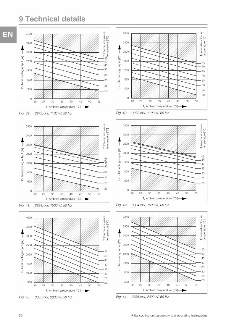
Fig. 39: 3273.xxx, 1100 W, 50 Hz Fig. 40: 3273.xxx, 1100 W, 60 Hz
2100
1800
1500
1200
900
600
300
0
555045
40
35
30
25
20
20 25 30 35 40 45 50 55T i
Inte
rnal
enc
losu
re
tem
per
atur
e [°
C]
Tu Ambient temperature [°C]
Pc
Tota
l coo
ling
out
put
[W
]
5550
45
40
35
30
25
20
20 25 30 35 40 45 50 55
2800
2400
2000
1800
1200
800
400
0
T iIn
tern
al e
nclo
sure
te
mp
erat
ure
[°C
]
Tu Ambient temperature [°C]
Pc
Tota
l coo
ling
out
put
[W
]
Fig. 41: 3384.xxx, 1500 W, 50 Hz Fig. 42: 3384.xxx, 1500 W, 60 Hz
3500
3000
2500
2000
1500
1000
500
0
55504540
35
30
25
20
20 25 30 35 40 45 50 55
T iIn
tern
al e
nclo
sure
te
mp
erat
ure
[°C
]
Tu Ambient temperature [°C]
Pc
Tota
l coo
ling
out
put
[W
]
3500
3000
2500
2000
1500
1000
500
0
55504540
35
30
25
20
20 25 30 35 40 45 50 55
T iIn
tern
al e
nclo
sure
te
mp
erat
ure
[°C
]
Tu Ambient temperature [°C]
Pc
Tota
l coo
ling
out
put
[W
]
Fig. 43: 3385.xxx, 2000 W, 50 Hz Fig. 44: 3385.xxx, 2000 W, 60 Hz
4000
3500
3000
2500
2000
1500
1000
500
55
50
45
40
35
30
25
2020 25 30 35 40 45 50 55
T iIn
tern
al e
nclo
sure
te
mp
erat
ure
[°C
]
Tu Ambient temperature [°C]
Pc
Tota
l coo
ling
out
put
[W
]
4000
3500
3000
2500
2000
1500
1000
500
55
50
45
40
35
30
25
20
20 25 30 35 40 45 50 55
T iIn
tern
al e
nclo
sure
te
mp
erat
ure
[°C
]
Tu Ambient temperature [°C]
Pc
Tota
l coo
ling
out
put
[W
]
30 Rittal cooling unit assembly and operating instructions

9 Tech ica detai s
E
9 2 2 3 phase by utput categ ryFig. 45: 3386.xxx, 3000 W, 50 Hz Fig. 46: 3386.xxx, 3000 W, 60 Hz
4900
4200
3500
2800
2100
1400
700
0
5550454035302520
20 25 30 35 40 45 50 55
T iIn
tern
al e
nclo
sure
te
mp
erat
ure
[°C
]Tu Ambient temperature [°C]
Pc
Tota
l coo
ling
out
put
[W
]
5250
4550
3850
3150
2450
1750
1050
350
5550454035
30
2520
20 25 30 35 40 45 50 55
T iIn
tern
al e
nclo
sure
te
mp
erat
ure
[°C
]
Tu Ambient temperature [°C]
Pc
Tota
l coo
ling
out
put
[W
]
Fig. 47: 3387.xxx, 4000 W, 50 Hz Fig. 48: 3387.xxx, 4000 W, 60 Hz
7000
6000
5000
4000
3000
2000
1000
0
55504540
35
30
25
20
20 25 30 35 40 45 50 55
Pc
Tota
l coo
ling
out
put
[W
]
Tu Ambient temperature [°C]
T iIn
tern
al e
n-cl
osur
e te
mpe
r-at
ure
[°C
]
7000
6000
5000
4000
3000
2000
1000
0
555045
40
35
30
25
20
20 25 30 35 40 45 50 55
T iIn
tern
al e
n-cl
osur
e te
mpe
r-at
ure
[°C
]
Tu Ambient temperature [°C]
Pc
Tota
l coo
ling
out
put
[W
]
Rittal cooling unit assembly and operating instructions 31

10 ist f spare parts
E
10 ist f spare partsFig. 49: Spare parts for 3359.xxx, 3382.xxx
Fig. 50: Spare parts for 3273.xxx, 3383.xxx, 3384.xxx, 3385.xxx
101
102
10071
45
55
255
1010
9595
7070
40
75
30
80
15
20
1
90
3359.xxx, 3382.xxx
101
15
95
25 20
45
55
100
75
30
90
5
71
1
10
70
80
40102
3273.xxx, 3383.xxx, 3384.xxx, 3385.xxx
32 Rittal cooling unit assembly and operating instructions

10 ist f spare parts
E
Fig. 51: Spare parts for 3386.xxx, 3387.xxx
ey1 Compressor5 Condenser fan10 Evaporator fan15 Dispatch bag20 Expansion valve25 Filter dryer30 PSAH pressure switch40 Controller board45 Louvred grille 55 Display71 Temperature sensor75 Enclosure tray80 Transformer90 Evaporator coil100 Condenser101 Condensate evaporator102 Miniature fuse, condensate evaporator
(T4A; 6.3 x 32 mm)
40
25
5
90
55
95
75
30
71
20
10
15
70
100100
1
45
101
102
3386.xxx, 3387.xxx
teAs well as the spare part number, when ordering spare parts the following information must be provided:– Unit model– Fabrication number– Date of manufactureThis information may be found on the rating plate.
Rittal cooling unit assembly and operating instructions 33

11 Appe dix Cut ut a d h e si es
E
11 Appe dix Cut ut a d h e si es11 1 Di e si s f r asse b y
Fig. 52: 3359.xxx, 3382.xxx assembly
Fig. 53: 3273.xxx, 3383.xxx, 3384.xxx, 3385.xxx assembly
Fig. 54: 3386.xxx, 3387.xxx assembly
375
415
326
170
597
415
365
Ø 80 30
475
260
326
375
597
475
415
420
280
597
415
380
Ø 100 27
490
597
420
390
475
580 52
0
392
796
692
470
796
538
Ø 150
38.5
580
238
Ø 150
34 Rittal cooling unit assembly and operating instructions

2nd
ed
ition
10.
2014
/ ID
no.
328
125
/ D
raw
ing
no.
A44
9130
1SK
23
� Enclosures� Power Distribution� Climate Control� IT Infrastructure� Software & Services
RITTAL GmbH & Co. KG Postfach 1662 � D-35726 HerbornPhone +49(0)2772 505-0 � Fax +49(0)2772 505-2319 E-mail: [email protected] � www.rittal.com