sannet ii 200 fibre channel array quick installation guide
TRANSCRIPT

SANnet II 200 Fibre Channel ArrayQuick Installation Guide
March 200583-00002625, Revision B

CopyrightCopyright 2005 Dot Hill Systems Corp. All rights reserved. No part of this publication may be reproduced, stored in a retrieval system, translated, transcribed, or transmitted, in any form or by any means – manual, electric, electronic, electromechanical, chemical, optical, or otherwise – without prior explicit written permission of Dot Hill Systems Corp., 6305 El Camino Real, P.O. Box 9000, Carlsbad, CA., 92009-1606.
TrademarksDot Hill Systems, the Dot Hill logo, SANscape, SANnet, and SANpath are registered trademarks of Dot Hill Systems Corp. All other trademarks and registered trademarks are proprietary to their respective owners.
ChangesThe material in this document is for information only and is subject to change without notice. While reasonable efforts have been made in the preparation of this document to assure its accuracy, Dot Hill Systems Corp., assumes no liability resulting from errors or omissions in this document, or from the use of the information contained herein. Dot Hill Systems Corp., reserves the right to make changes in the product design without reservation and without notification to its users.
Contents
1. Getting Started . . . . . . . . . . . . . . . . . . . . . . . . . . . . . . . . . . . . . . . . . . . . . . . . . . . . . 1–1
1.1 Refer to Your Release Notes . . . . . . . . . . . . . . . . . . . . . . . . . . . . . . . . . . . . . . 1–2
1.2 Site Planning . . . . . . . . . . . . . . . . . . . . . . . . . . . . . . . . . . . . . . . . . . . . . . . . . . 1–2
1.3 Unpacking the Array . . . . . . . . . . . . . . . . . . . . . . . . . . . . . . . . . . . . . . . . . . . . 1–2
1.4 Mounting Your FC Array in a Rack or Cabinet . . . . . . . . . . . . . . . . . . . . . . . . . 1–3
1.5 Related Documentation . . . . . . . . . . . . . . . . . . . . . . . . . . . . . . . . . . . . . . . . . . 1–3
1.6 What to Do Next . . . . . . . . . . . . . . . . . . . . . . . . . . . . . . . . . . . . . . . . . . . . . . . 1–3
2. Connecting Your FC Array . . . . . . . . . . . . . . . . . . . . . . . . . . . . . . . . . . . . . . . . . . . . 2–1
2.1 SANnet II 200 FC Array Connections . . . . . . . . . . . . . . . . . . . . . . . . . . . . . . . 2–2
2.2 Connecting the Chassis to AC Power Outlets . . . . . . . . . . . . . . . . . . . . . . . . . 2–3
2.3 Connecting the Chassis to DC Power Outlets . . . . . . . . . . . . . . . . . . . . . . . . . 2–4
2.4 Cabling to Expansion Units . . . . . . . . . . . . . . . . . . . . . . . . . . . . . . . . . . . . . . . 2–5
2.5 Setting Loop IDs on Expansion Units . . . . . . . . . . . . . . . . . . . . . . . . . . . . . . . 2–7
2.6 Powering Up and Checking LEDs . . . . . . . . . . . . . . . . . . . . . . . . . . . . . . . . . 2–10
2.7 Reviewing Channels, Ports, and SFPs . . . . . . . . . . . . . . . . . . . . . . . . . . . . . 2–11
2.7.1 Drive Port Connectivity in a Dual-Controller Array . . . . . . . . . . . . . . 2–12
2.7.1.1 SANnet II 200 FC Array Drive Ports . . . . . . . . . . . . . . . . 2–12
2.7.2 Host Port Connectivity in a Dual-Controller Array . . . . . . . . . . . . . . 2–12
2.7.2.1 SANnet II 200 FC Array Host Ports . . . . . . . . . . . . . . . . . 2–13
2.7.3 Default SFP Placement . . . . . . . . . . . . . . . . . . . . . . . . . . . . . . . . . . 2–13
2.7.4 Changing Your SFP Configuration . . . . . . . . . . . . . . . . . . . . . . . . . . 2–15
2.8 Establishing Communications With An Array . . . . . . . . . . . . . . . . . . . . . . . . . 2–16
2.9 Configuring a Host COM Port to Connect to a RAID Array . . . . . . . . . . . . . . 2–17
2.10 Manually Setting a Static IP Address . . . . . . . . . . . . . . . . . . . . . . . . . . . . . . 2–17
iii

2.11 Setting Up Out-of-Band Management Over Ethernet . . . . . . . . . . . . . . . . . .2–18
2.12 Scaling a SANnet II 200 FC Array Into a High-Capacity Configuration . . . . .2–20
2.13 Adding an Expansion Unit to an Existing RAID Array . . . . . . . . . . . . . . . . . .2–21
2.14 Connecting Ports to Hosts . . . . . . . . . . . . . . . . . . . . . . . . . . . . . . . . . . . . . . .2–21
2.15 Power-On Sequence . . . . . . . . . . . . . . . . . . . . . . . . . . . . . . . . . . . . . . . . . . .2–22
2.16 Powering Off the Array . . . . . . . . . . . . . . . . . . . . . . . . . . . . . . . . . . . . . . . . .2–23
iv SANnet II 200 FC Array Quick Installation Guide • March 2005

CHAPTER 1
Getting Started
This guide provides basic instructions on how to unpack and connect your SANnet II 200 Fibre Channel (FC) array.
Figure 1-1 SANnet II 200 FC Array (Front View)
This chapter includes the following topics:■ “Refer to Your Release Notes” on page 1-2■ “Site Planning” on page 1-2■ “Unpacking the Array” on page 1-2■ “Mounting Your FC Array in a Rack or Cabinet” on page 1-3■ “Related Documentation” on page 1-3■ “What to Do Next” on page 1-3
1-1

1.1 Refer to Your Release NotesRefer to the SANnet II 200 FC Array Release Notes to see late-breaking information including required patches and supported hardware and software. The release notes and other documentation for this product are available online at:
http://www.dothill.com/manuals
1.2 Site Planning Refer to the SANnet II 200 FC, SATA, and SATA SE Array Installation, Operation, and Service Manual to see detailed information about preinstallation site planning. Fill out the preinstallation worksheet before you unpack and set up your SANnet II 200 FC array.
1.3 Unpacking the ArrayFollow these guidelines for unpacking the equipment.
Caution – Always use two people to remove the unit from its container, to avoid personal injury or damage to the equipment during installation. This unit weighs approximately 60 pounds (27 kg).
1. Select a suitable area for unpacking.
2. Store all packing material and boxes for possible equipment returns.
3. Check the Contents Sheet in your product package.The Contents Sheet summarizes the standard contents for your product.
4. Compare the packing slip and the list of parts with the items you received. If the list of parts on your packing slip does not match the items you received, or any items appear damaged, immediately notify your carrier agent and the supplier who prepared your shipment.
5. Carefully examine the cables provided in the package. If any cable appears to be damaged, contact the Technical Service department for an immediate replacement.
6. To complete the installation, you must provide a minimum of one fiber-optic cable per host to connect a host to a RAID array. Two fiber-optic cables are required for a redundant path configuration.
To obtain qualified cables, consult your Dot Hill sales representative.
1-2 SANnet II 200 FC Array Quick Installation Guide • March 2005
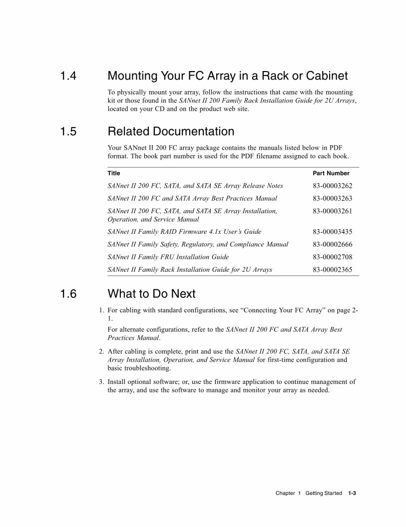
1.4 Mounting Your FC Array in a Rack or CabinetTo physically mount your array, follow the instructions that came with the mounting kit or those found in the SANnet II 200 Family Rack Installation Guide for 2U Arrays, located on your CD and on the product web site.
1.5 Related DocumentationYour SANnet II 200 FC array package contains the manuals listed below in PDF format. The book part number is used for the PDF filename assigned to each book.
1.6 What to Do Next1. For cabling with standard configurations, see “Connecting Your FC Array” on page 2-
1.For alternate configurations, refer to the SANnet II 200 FC and SATA Array Best Practices Manual.
2. After cabling is complete, print and use the SANnet II 200 FC, SATA, and SATA SE Array Installation, Operation, and Service Manual for first-time configuration and basic troubleshooting.
3. Install optional software; or, use the firmware application to continue management of the array, and use the software to manage and monitor your array as needed.
Title Part Number
SANnet II 200 FC, SATA, and SATA SE Array Release Notes 83-00003262
SANnet II 200 FC and SATA Array Best Practices Manual 83-00003263
SANnet II 200 FC, SATA, and SATA SE Array Installation, Operation, and Service Manual
83-00003261
SANnet II Family RAID Firmware 4.1x User’s Guide 83-00003435
SANnet II Family Safety, Regulatory, and Compliance Manual 83-00002666
SANnet II Family FRU Installation Guide 83-00002708
SANnet II Family Rack Installation Guide for 2U Arrays 83-00002365
Chapter 1 Getting Started 1-3

1-4 SANnet II 200 FC Array Quick Installation Guide • March 2005

CHAPTER 2
Connecting Your FC Array
This chapter describes procedures for cabling the SANnet II 200 FC array and for connecting an array to power and to network devices.
The following topics are covered in this chapter:■ “SANnet II 200 FC Array Connections” on page 2-2■ “Connecting the Chassis to AC Power Outlets” on page 2-3■ “Connecting the Chassis to DC Power Outlets” on page 2-4■ “Cabling to Expansion Units” on page 2-5■ “Setting Loop IDs on Expansion Units” on page 2-7■ “Powering Up and Checking LEDs” on page 2-10■ “Reviewing Channels, Ports, and SFPs” on page 2-11
■ “Drive Port Connectivity in a Dual-Controller Array” on page 2-12■ “Host Port Connectivity in a Dual-Controller Array” on page 2-12■ “Default SFP Placement” on page 2-13■ “Changing Your SFP Configuration” on page 2-15
■ “Establishing Communications With An Array” on page 2-16■ “Configuring a Host COM Port to Connect to a RAID Array” on page 2-17■ “Manually Setting a Static IP Address” on page 2-17■ “Setting Up Out-of-Band Management Over Ethernet” on page 2-18■ “Scaling a SANnet II 200 FC Array Into a High-Capacity Configuration” on
page 2-20■ “Adding an Expansion Unit to an Existing RAID Array” on page 2-21■ “Connecting Ports to Hosts” on page 2-21■ “Power-On Sequence” on page 2-22■ “Powering Off the Array” on page 2-23
Before you connect the array to the network, position the array in the rack, cabinet, or other location where it will be used.
2-1

Caution – When positioning the array, do not block the air vents at the front or back of the unit. Follow all safety precautions specified in the SANnet II Family Safety, Regulatory, and Compliance Manual.
Caution – When you power off an array, wait five seconds before you power it back on. If you power the array off and on too quickly, unexpected results can occur. For more information, refer to the SANnet II 200 FC, SATA, and SATA SE Installation, Operation, and Service Manual.
2.1 SANnet II 200 FC Array ConnectionsFigure 2-1 identifies the hardware connections on the back of a dual-controller SANnet II 200 FC array.
Figure 2-1 Hardware Connections on the Back of a Dual-Controller SANnet II 200 FC Array
FC device connectionsapplication/data servers and consoles
FC expansion units/FC arrays
FC devices Servers and consoles
Managementconsole
2-2 SANnet II 200 FC Array Quick Installation Guide • March 2005

Management is in-band through fibre host connections and out-of-band through the serial port and Ethernet port on the back of each controller.
2.2 Connecting the Chassis to AC Power OutletsWhen you connect the AC power cords, install the two provided cord locks at the same time. The AC cord locks are used to securely fasten the AC cable connectors.
Caution – If the array is connected to AC power sources not within the designated 90–135 or 180–264 VAC range, the unit might be damaged.
Note – To ensure power redundancy, be sure to connect the two power supply modules to two separate circuits (for example, one commercial circuit and one UPS).
To connect the AC power cords, perform the following procedure.
1. Use a Phillips screwdriver to remove the screw and cylindrical standoff from one of the two provided cord locks.Set them aside for reassembly later.
2. Slide the cord lock over the AC power connector.
3. Hold the cylindrical standoff between the two screw holes on the flanges of the cord lock.
4. Insert the screw into the first screw hole, through the standoff, and then into the threaded screw hole on the other flange.
5. Tighten the screw with a screwdriver until the flanges bottom out on the cylindrical standoff.
6. Push the power cord into the power supply receptacle until it is firmly seated.
7. Push the green ejector handle forward until it is seated against the power supply.
8. Turn the thumbscrew of the green ejector handle clockwise until it is finger-tight to secure the handle and the cord lock.
Note – To ensure that a thumbscrew is finger-tight, tighten it with a screwdriver and then loosen the thumbscrew counterclockwise a quarter turn.
9. Repeat Step 1 through Step 8 for the second cord lock and second power cable.
Chapter 2 Connecting Your FC Array 2-3

Figure 2-2 Installing a Cord Lock
2.3 Connecting the Chassis to DC Power OutletsTwo DC power cords are packaged with each DC array. To connect the DC power cords, perform the following procedure.
1. Check the DC cable part number and wire labels carefully before connecting the cable to the source.
Table 2-1 DC Cable Wiring for Cable 35-00000148
Pin Number Voltage Color
A3 Return Red
A2 GND (Chassis Ground) Green/Yellow
A1 –48 VDC Black
1
3
2
4
2-4 SANnet II 200 FC Array Quick Installation Guide • March 2005

2. Connect a DC power cable to the first power supply and to a power outlet.
Note – Use only the DC power cables provided with the array.
Caution – If the array is connected to DC power sources not within the designated –48V DC (–36 VDC to –72 VDC) range, the unit might be damaged.
Note – To ensure power redundancy, be sure to connect the two power supply modules to two separate circuits (for example, one commercial circuit and one UPS).
Note – To extend the length of the DC power cable as needed, strip the last 1/4 inch of the cable, insert the stripped end into a provided Panduit tube, and crimp the tube.
3. Tighten the cable-locking screws to attach the cable securely to the power supply power outlet.
4. Connect the second power cable to the second power supply and to a second power outlet. Tighten the cable-locking screws. If one power supply fails, the second power supply automatically takes the full load.
2.4 Cabling to Expansion Units
Caution – When connecting expansion units to a RAID array, always connect channel 2 of the RAID array to the A channel of the expansion units, and connect channel 3 of the RAID array to the B channel of the expansion units. Otherwise, unexpected behavior might occur.
Several cabling configurations are possible, each with its own advantages and disadvantages. Refer to the SANnet II 200 FC and SATA Array Best Practices Manual for more information about the suitability of various configurations for various application requirements, as well as for information about high-capacity configurations.
Table 2-2 DC Cable Wiring for Cable 35-00000156
Pin Number Voltage Color
A3 L+ Red
A2 GND (Chassis Ground) Green/Yellow
A1 L– White
Chapter 2 Connecting Your FC Array 2-5
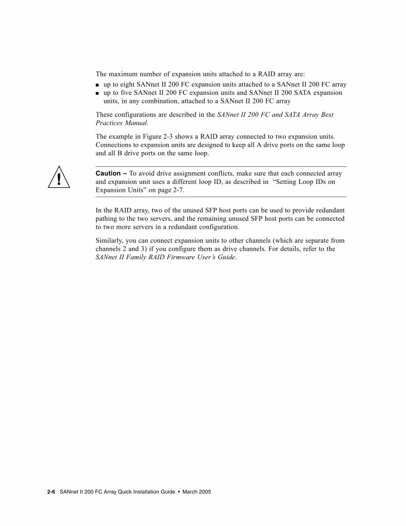
The maximum number of expansion units attached to a RAID array are:■ up to eight SANnet II 200 FC expansion units attached to a SANnet II 200 FC array■ up to five SANnet II 200 FC expansion units and SANnet II 200 SATA expansion
units, in any combination, attached to a SANnet II 200 FC array
These configurations are described in the SANnet II 200 FC and SATA Array Best Practices Manual.
The example in Figure 2-3 shows a RAID array connected to two expansion units. Connections to expansion units are designed to keep all A drive ports on the same loop and all B drive ports on the same loop.
Caution – To avoid drive assignment conflicts, make sure that each connected array and expansion unit uses a different loop ID, as described in “Setting Loop IDs on Expansion Units” on page 2-7.
In the RAID array, two of the unused SFP host ports can be used to provide redundant pathing to the two servers, and the remaining unused SFP host ports can be connected to two more servers in a redundant configuration.
Similarly, you can connect expansion units to other channels (which are separate from channels 2 and 3) if you configure them as drive channels. For details, refer to the SANnet II Family RAID Firmware User’s Guide.
2-6 SANnet II 200 FC Array Quick Installation Guide • March 2005

Figure 2-3 SANnet II 200 FC Array Attached to Two Hosts and Two Expansion Units
2.5 Setting Loop IDs on Expansion UnitsWhen an expansion unit is attached to a RAID array, unique, hard-assigned loop IDs are assigned to each expansion unit drive. A loop ID is the decimal version of an arbitrated loop physical address (AL_PA). The lowest number loop ID is the lowest priority address on the loop.
RAID array
Expansion unit 1
Expansion unit 2
Loop A (top drive ports) Loop B (bottom drive ports)
Cable to drive
Cable to host
Chapter 2 Connecting Your FC Array 2-7

On the left front side of an expansion unit, an ID switch is used to set the loop IDs for the disk drives to a different range of values so that the same IDs are not repeated by RAID units and expansion units on the same loop.
Setting the loop ID on an array or expansion unit requires dropping the front bezel out of the way and removing the small vertical plastic cap on the left side of the bezel that covers the left rackmount tab. Rackmount tabs are also referred to as “ears.”
Figure 2-4 Front Bezel and Front Bezel Locks of an Array
1. Use the provided key to unlock both bezel locks.
2. Grasp the front bezel cover on both sides and pull it forward and then down.
3. Remove the plastic cap from the left ear of the array.
a. Squeeze both sides of the cap at the top and the bottom.
b. Turn the cap toward the center of the array until it disengages and pull it free.
Caution – To avoid damage to the cap, do not pull the cap forward directly or pull from only its top or bottom.
The ID switch is exposed when you remove the plastic cap.
Figure 2-5 ID Switch Located on the Left Front Side of Arrays and Expansion Units
4. Press the upper or lower switch button to change the ID number so that each connected RAID array and expansion unit uses a different loop ID.
Bezel locksPlastic “ear” cap covering loop ID switch
Press to change the ID number
2-8 SANnet II 200 FC Array Quick Installation Guide • March 2005
Caution – The loop ID should only be changed while the expansion unit is powered off or not in use. After changing the loop ID, a power cycle is required to make the ID switch change take effect. Failure to cycle the power following a loop ID change can lead to unexpected results.
The default ID switch setting for RAID arrays is 0. The default range of available drive IDs for RAID arrays is 0 to 11 for 12 drives (the IDs 12–15 are ignored). The default ID switch setting for expansion units and JBODs is 1.
Ensure that the loop IDs of expansion units do not duplicate the loop IDs of other connected expansion units or RAID arrays.
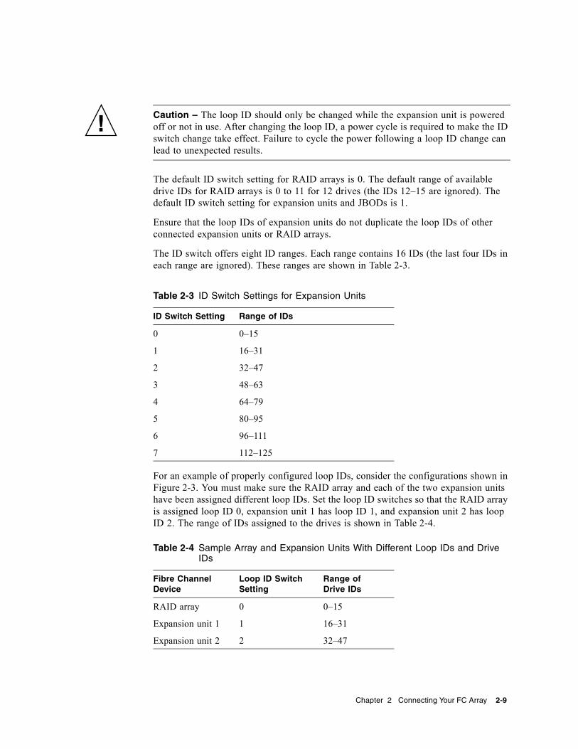
The ID switch offers eight ID ranges. Each range contains 16 IDs (the last four IDs in each range are ignored). These ranges are shown in Table 2-3.
For an example of properly configured loop IDs, consider the configurations shown in Figure 2-3. You must make sure the RAID array and each of the two expansion units have been assigned different loop IDs. Set the loop ID switches so that the RAID array is assigned loop ID 0, expansion unit 1 has loop ID 1, and expansion unit 2 has loop ID 2. The range of IDs assigned to the drives is shown in Table 2-4.
Table 2-3 ID Switch Settings for Expansion Units
ID Switch Setting Range of IDs
0 0–15
1 16–31
2 32–47
3 48–63
4 64–79
5 80–95
6 96–111
7 112–125
Table 2-4 Sample Array and Expansion Units With Different Loop IDs and Drive IDs
Fibre Channel Device
Loop ID Switch Setting
Range of Drive IDs
RAID array 0 0–15
Expansion unit 1 1 16–31
Expansion unit 2 2 32–47
Chapter 2 Connecting Your FC Array 2-9

5. Prepare the plastic left ear cap for replacement by aligning the inside round notches of the cap with the round cylindrical posts (ball studs) on the ear.
6. Push the top and bottom of the ear cap onto the ear, pressing in on the top side toward the center of the array first.
7. Continue pushing the top and bottom of the ear cap onto the ear, pressing on the side toward the outside of the array.Do not use force when placing a cap on an ear.
8. Lift the bezel into position and press it onto the front of the chassis until it is flush with the front.
9. Use the key to lock both bezel locks.
2.6 Powering Up and Checking LEDsPerform the initial check of the array according to the following procedure.
1. Connect two AC or DC power cables to the power and fan modules on the back of the array.
2. Power on the array by turning on each power switch.
3. Check for the following LED activity:All front-panel LEDs turn solid green to indicate good operation.
Note – Whenever media scan is running on a drive, its front-panel LED flashes green and continues to flash as long as media scan is running. Media scan must be started from the firmware application. If the host is restarted, then media can must be manually restarted. For more information, refer to the SANnet II Family RAID Firmware User’s Guide.
2-10 SANnet II 200 FC Array Quick Installation Guide • March 2005

Figure 2-6 Front Panel of the SANnet II 200 FC Array With LEDs Displayed
For further information about your array’s LEDs, refer to the SANnet II 200 FC, SATA, and SATA SE Array Installation, Operation, and Service Manual.
2.7 Reviewing Channels, Ports, and SFPsI/O controller modules have ports that accept small form-factor pluggable (SFP) transceivers. These ports are labeled FC0 through FC5, to indicate channels 0 through 5. Default configurations do not include an SFP connector in every SFP port. To add or change SFP connectors, see to “Changing Your SFP Configuration” on page 2-15.
The channels and associated ports for the SANnet II 200 FC arrays are summarized in Table 2-5.
Table 2-5 Number of Ports in SANnet II 200 FC Arrays
Item SANnet II 200 FC Array
Total number of ports 6
Channel 0 1 FC0 host or drive port; default: host port
Channel 1 1 FC1 host or drive port; default: host port
Channel 2 1
1. Channel 2 drive ports connect to drive loop A ports on expansion units.
1 FC2 dedicated drive port
Channel 3 2
2. Channel 3 drive ports connect to drive loop B ports on expansion units.
1 FC3 dedicated drive port
Channel 4 1 FC4 host or drive port; default: host port
Channel 5 1 FC5 host or drive port; default: host port
Disk 0
Disk 1
Disk 2
Disk 3
Disk 4
Disk 5
Disk 6
Disk 7
Disk 8
Disk 9
Disk 10
Disk 11
Chapter 2 Connecting Your FC Array 2-11
2.7.1 Drive Port Connectivity in a Dual-Controller Array
Drive channels connect to the internal drives in the array and can also connect to drives in external expansion units. The SANnet II 200 FC array has a drive channel assigned to two ports on each I/O controller module. Each drive channel is a pair of ports on a single I/O controller module. In a dual-controller configuration, the top controller has two ports for drive channel 2, and the lower I/O controller module has two ports for drive channel 3.
2.7.1.1 SANnet II 200 FC Array Drive Ports
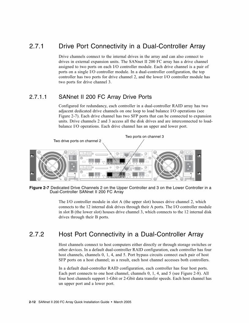
Configured for redundancy, each controller in a dual-controller RAID array has two adjacent dedicated drive channels on one loop to load balance I/O operations (see Figure 2-7). Each drive channel has two SFP ports that can be connected to expansion units. Drive channels 2 and 3 access all the disk drives and are interconnected to load-balance I/O operations. Each drive channel has an upper and lower port.
Figure 2-7 Dedicated Drive Channels 2 on the Upper Controller and 3 on the Lower Controller in a Dual-Controller SANnet II 200 FC Array
The I/O controller module in slot A (the upper slot) houses drive channel 2, which connects to the 12 internal disk drives through their A ports. The I/O controller module in slot B (the lower slot) houses drive channel 3, which connects to the 12 internal disk drives through their B ports.
2.7.2 Host Port Connectivity in a Dual-Controller Array
Host channels connect to host computers either directly or through storage switches or other devices. In a default dual-controller RAID configuration, each controller has four host channels, channels 0, 1, 4, and 5. Port bypass circuits connect each pair of host SFP ports on a host channel; as a result, each host channel accesses both controllers.
In a default dual-controller RAID configuration, each controller has four host ports. Each port connects to one host channel, channels 0, 1, 4, and 5 (see Figure 2-8). All four host channels support 1-Gbit or 2-Gbit data transfer speeds. Each host channel has un upper port and a lower port.
Two drive ports on channel 2Two ports on channel 3
2-12 SANnet II 200 FC Array Quick Installation Guide • March 2005

2.7.2.1 SANnet II 200 FC Array Host Ports
In a default dual-controller RAID configuration, each controller has four host ports. Each port connects to one host channel, channels 0, 1, 4, and 5 (see Figure 2-8). All four host channels support 1-Gbit or 2-Gbit data transfer speeds. Each host channel has un upper port and a lower port.
Figure 2-8 Host Channels on a Dual-Controller SANnet II 200 FC Array
2.7.3 Default SFP Placement
Default configurations do not include an SFP connector in every SFP port. You might want to add or rearrange SFPs, depending on the configuration mode (loop or point-to-point), the number of planned host connections, the necessary number of redundant connections to hosts, and the number of expansion units needed.
The supported SFP is a single-port, optical SFP transceiver for multimode (short wave) or single-mode (long wave) use. It is compatible with the Small Form Factor Pluggable Multi-Sourcing Agreement (MSA, Sep. 2000), and 1x and 2x Fiber Channel. The optical connector used is the low-profile LC connector.
SFPs are Dot Hill field-replaceable units (FRUs) and can be ordered from Dot Hill. These SFPs have been selected and tested to provide the necessary reliability and performance. SFPs from other vendors are not supported.
To review various configuration options, refer to the SANnet II 200 FC, SATA, and SATA SE Array Installation, Operation, and Service Manual and the SANnet II 200 FC and SATA Array Best Practices Manual.
In dual-controller arrays, SFPs are initially plugged into one of each pair of host and drive ports. The default port connections are:■ The upper I/O controller module has SFPs in the FC0, FC2, and FC4 ports.■ The lower I/O controller module has SFPs in the FC1, FC3, and FC5 ports.
This configuration provides connections to all six host channels as well as to both drive channels (see Figure 2-9).
Host channel 0 Host channel 1Host channel 4 Host channel 5
An upper port and a lower port are on each host channel.
Chapter 2 Connecting Your FC Array 2-13
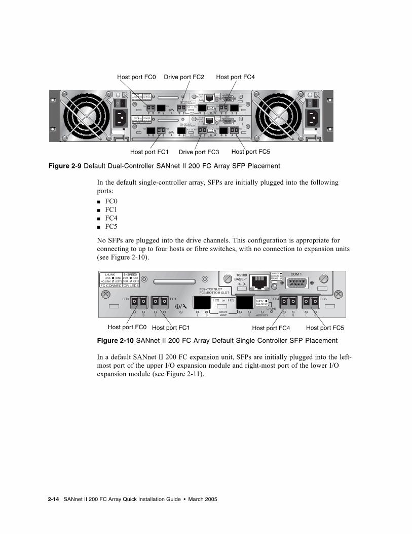
Figure 2-9 Default Dual-Controller SANnet II 200 FC Array SFP Placement
In the default single-controller array, SFPs are initially plugged into the following ports:■ FC0■ FC1■ FC4■ FC5
No SFPs are plugged into the drive channels. This configuration is appropriate for connecting to up to four hosts or fibre switches, with no connection to expansion units (see Figure 2-10).
Figure 2-10 SANnet II 200 FC Array Default Single Controller SFP Placement
In a default SANnet II 200 FC expansion unit, SFPs are initially plugged into the left-most port of the upper I/O expansion module and right-most port of the lower I/O expansion module (see Figure 2-11).
Host port FC0 Drive port FC2 Host port FC4
Host port FC1 Drive port FC3 Host port FC5
Host port FC0 Host port FC1 Host port FC4 Host port FC5
2-14 SANnet II 200 FC Array Quick Installation Guide • March 2005

Figure 2-11 SANnet II 200 FC JBOD/Expansion Unit Default SFP Placement
2.7.4 Changing Your SFP Configuration
SANnet II 200 FC arrays use SFP connectors to attach to hosts and expansion units. These SFP connectors resemble the one shown in Figure 2-12, with a single connector at the end that plugs into an SFP port on the array or expansion unit chassis, and a duplex jack into which you insert a cable to make the connection.■ To connect to an empty port, first slide the SFP connector into the port so that it
connects firmly with the chassis. Then plug the fiber-optic cable’s SFP connector into the duplex jack at the end of the SFP.
■ To remove an SFP connector, remove the cable if one is connected to it, and then slide the SFP out from the port.
Figure 2-12 Typical SFP Connector Used to Connect Cables to Chassis SFP Ports
Default SFP Placement
Chapter 2 Connecting Your FC Array 2-15

2.8 Establishing Communications With An ArrayBefore you can configure an array, you must establish one or more communication links between at least one host and an array. You can use any combination of the array’s RS-232 COM (serial) port, the Ethernet port, and the in-band data connection between the host and the array.■ A direct RS-232 port connection guarantees that a host can communicate with a
RAID array even if the array’s IP address changes or is unknown, or if the TCP/IP network suffers a temporary outage. See “Configuring a Host COM Port to Connect to a RAID Array” on page 2-17 for more information.
■ SANnet II 200 FC, SATA, and SATA SE arrays ship with the Dynamic Host Configuration Protocol (DHCP) TCP/IP network support protocol enabled. If your network uses a DHCP server to dynamically and automatically allocate IP addresses to attached devices, as soon as the RAID array is powered up an IP address is assigned to it. You can use this IP address to monitor and manage the array’s firmware through telnet sessions. See “Setting Up Out-of-Band Management Over Ethernet” on page 2-18 for information about setting up a telnet session.
■ A fixed IP address enables you to use telnet or other out-of-band management sessions to manage the array with no risk of a DHCP server changing its IP address. See “Setting Up Out-of-Band Management Over Ethernet” on page 2-18 for information.
When the array is first powered up, the default IP address setting uses the IP address assigned by a DHCP server. If the RAID array is connected to a network with an active DHCP server, you can determine the IP address assigned to the array in several ways:■ If you have access to the controller firmware, from the Main Menu choose
Configuration Parameters → Communication Parameters → Internet Protocol (TCP/IP). If the RAID controller is not on a network connected to an active DHCP server, “DHCP Client” is displayed rather than a DHCP-assigned IP address. Refer to the “Configuration Parameters” chapter in the SANnet II Family RAID Firmware User's Guide for more information.
■ Use the show network-parameters CLI command. Refer to the SANscape CLI User's Guide for more information. If the RAID controller is not on a network connected to an active DHCP server, an IP address of 0.0.0.0 is displayed. Refer to the SANscape CLI User's Guide for more information.
■ Use the Change Network Settings window in SANscape. Refer to the “Updating the Configuration” chapter in the SANscape User’s Guide for more information.
■ Enable the controller firmware to send event messages using SNMP. Event messages sent as SNMP traps to the email address you specify contain the IP address of the array from which it is sent. Refer to the “Configuration Parameters” chapter in the SANnet II Family RAID Firmware User's Guide for more information.
Once you have determined the RAID controller’s IP address using one of these methods, you can establish a telnet session to that IP address. However, because of the dynamic nature of DHCP-assigned IP addresses, the RAID array’s IP address might change in the event of a controller reset, a network outage, or if the DHCP server is
2-16 SANnet II 200 FC Array Quick Installation Guide • March 2005

rebooted. If this happens, telnet sessions to the previous IP address can no longer communicate with the array, and it is necessary to use one of the methods described above to determine the new IP address.
If you do not have an active DHCP server on the same network as the RAID array, or if you prefer to have a fixed IP address, use the procedures in “Setting Up Out-of-Band Management Over Ethernet” on page 2-18.
2.9 Configuring a Host COM Port to Connect to a RAID ArrayThe RS-232 COM (serial) port on either controller module can be used to configure and monitor the RAID array using the controller firmware. It can be connected to a VT100 terminal, terminal emulation program, terminal server, or the serial port of a server.
1. Use a null modem serial cable to connect the COM port of the RAID array to the serial port on a host workstation.A null modem serial cable is included in your package.
2. Set the serial port parameters on the workstation as follows:■ 38,400 baud■ 8 bit■ 1 stop bit■ No parityFor more information, refer to the SANnet II 200 FC, SATA, and SATA SE Installation, Operation, and Service Manual.
2.10 Manually Setting a Static IP AddressYou can manually set an array’s IP address using the controller’s firmware by typing values for the IP address, the subnet mask, and IP address of the gateway. If your network uses a Reverse Address Resolution Protocol (RARP) server or a Dynamic Host Configuration Protocol (DHCP) server to automatically configure IP information for devices on the network, you can specify the appropriate protocol instead of typing the information manually.
Note – If you assign an IP address to an array to manage it out-of-band, for security reasons consider using an IP address on a private network rather than a publicly routable network.
Chapter 2 Connecting Your FC Array 2-17

To set the IP address, subnet mask, and gateway address of the RAID controller, perform the following steps.
1. Access the array through the COM port on the I/O Controller module or through a telnet session to the existing IP address.
2. From the controller firmware’s Main Menu, choose view and edit Configuration parameters → Communication Parameters → Internet Protocol (TCP/IP).
3. Select the chip hardware address and MAC address that is displayed.
4. Choose Set IP Address → Address.
5. Type in the desired IP address, subnet mask (if it is not automatically supplied), and gateway address, choosing each menu option in turn, backspacing over any existing entries.If your network sets IP addresses using a RARP server and you prefer using it to using a fixed IP address, type RARP rather than an IP address, and do not type in a subnet mask or gateway address. If your network sets IP addresses using a DHCP server and you prefer using it to using a fixed IP address, type DHCP rather than an IP address, and do not type a subnet mask or gateway address.
6. Press Esc to continue.A confirmation prompt is displayed.
7. Choose Yes to continue.
Note – You must reset the controller for the configuration to take effect.
You are prompted to reset the controller.
8. Choose Yes to reset the controller.The controller takes a few minutes to format a small storage sector on each physical drive before logical drives can be successfully initialized.
2.11 Setting Up Out-of-Band Management Over EthernetThe controller Ethernet port offers interactive out-of-band management through the following interfaces:■ The SANscape application. Refer to the SANscape User’s Guide for details. ■ The SANscape Command-Line Interface (CLI). Refer to the SANscape CLI User’s
Guide for details.
Change/Set IP Address ?
2-18 SANnet II 200 FC Array Quick Installation Guide • March 2005

■ The firmware application you access when you use the telnet command to connect to the IP address of the controller.
Using an Ethernet connection, you can configure and monitor RAID arrays and expansion units remotely by using the telnet command to access the firmware application on the array and by using the SANscape or SANscape CLI software.
Caution – If you assign an IP address to an array to manage it out-of-band, for security reasons consider using an IP address on a private network rather than a publicly routable network.
1. To access the RAID array over an Ethernet connection, first connect the RAID array’s Ethernet port on each controller to the network.
Note – SANnet II family arrays require at least CAT-5 Ethernet cable.
Note – In a dual-controller RAID array, be sure to connect both Ethernet ports to the network. This provides failover if one controller fails.
2. Establish the IP address of the RAID array, as described in “Establishing Communications With An Array” on page 2-16.
3. To use the firmware application program from the host server, connect to the IP address of the RAID array controller with the following command:
Note – Alternatively, you can use the Solaris operating system tip command or a terminal emulation program to access the firmware application program. See “Configuring a Host COM Port to Connect to a RAID Array” on page 2-17 for more information.
4. Press Ctrl-L to refresh the screen and view the Main Menu.
Note – If you reset the controller during a telnet session, you are disconnected from the RAID array. Use the telnet command to login to the array again.
# telnet IP-address
Chapter 2 Connecting Your FC Array 2-19

To connect the SANscape program (on a host server) to a RAID array that has an IP address, refer to the out-of-band management instructions in the SANscape User’s Guide.The same document’s “Email and SNMP” appendix provides information about configuring SANscape software to use Simple Network Management Protocol (SNMP) traps and Management Information Bases (MIBs) to provide information to other out-of-band enterprise management software. The “Monitoring the Array” chapter explains the use of SANscape agents to redirect event messages into host system logs.
You can also enable the controller firmware to send event messages using SNMP. Refer to the “Configuration Parameters” chapter in the SANnet II Family RAID Firmware User's Guide for more information.
2.12 Scaling a SANnet II 200 FC Array Into a High-Capacity Configuration
Note – High-capacity SANnet II 200 FC array configurations are supported with certain limitations. A SANnet II 200 FC array with more than two expansion units is a high-capacity configuration.
SANnet II 200 FC arrays typically allow the connection of up to two expansion units to support a maximum of 36 disks. However, you can create larger configurations that support as many as eight expansion units and up to 108 disks if you use the guidelines in this section.
Carefully consider the following limitations of special high-capacity configurations. Using multiple SANnet II 200 FC arrays connected to the same SAN normally provides significantly better performance than one high-capacity configuration.■ Maximize the size of each logical drive (up to 1908 Gbyte) before creating another
logical drive in order to allow for maximum storage capacity. ■ SANnet II 200 FC arrays can be connected to SANnet II 200 FC expansion units.
They can also be connected to a maximum of five SANnet II 200 SATA expansion units and SANnet II 200 FC expansion units, in any combination.
Refer to the SANnet II 200 FC and SATA Array Best Practices Manual for more information and sample cabling diagrams.
Note – Large configurations might require the use of one or more optional extended-length cables. Other items might also be required. Refer to the SANnet II Family FRU Installation Guide for information about supported cables, SFPs, and other user-replaceable items.
2-20 SANnet II 200 FC Array Quick Installation Guide • March 2005

2.13 Adding an Expansion Unit to an Existing RAID ArrayTo install an expansion unit to an existing, configured RAID array, perform the following steps.
1. Stop I/O and shut down the controller to ensure that all data in the cache is written to disk.For details on shutting down the controller, see “Powering Off the Array” on page 2-23.
2. Verify that the loop ID of the expansion unit is set to a different ID than the RAID unit and any expansion units already attached.For details on loop IDs, see “Setting Loop IDs on Expansion Units” on page 2-7.
3. Physically cable the new expansion unit to the array using a valid cabling configuration. Refer to the SANnet II 200 FC and SATA Array Best Practices Manual for your array for more information on expansion unit cabling configurations.
4. Power on the expansion units.For details on the power-on sequence, see “Power-On Sequence” on page 2-22.
5. Power on the RAID array.
6. Verify the SES/PLD (programmable logic device) version of the expansion unit and the RAID array.To review the version information, using the SANscape CLI, type show ses. Or, using SANscape, open the View Enclosure window.
7. If the SES/PLD version is not the same for the RAID array and the expansion unit, download the latest SES/PLD firmware from the Dot Hill web site: http://www.dothill.com.
a. Choose Support → Downloads.
b. Click Firmware Downloads.
c. Enter the required information, and click Submit.
Choose and download the appropriate SES/PLD firmware.
2.14 Connecting Ports to HostsIn a default array configuration, channels 0, 1, 4, and 5 are host channels, so you can directly connect an array to four host computers. SFP connectors are plugged into channels 0 and 4 on the upper controller and channels 1 and 5 on the lower controller for this purpose.
Chapter 2 Connecting Your FC Array 2-21

If you want to connect a SANnet II 200 FC array to more than four host computers without changing the default configuration, you can connect these four host channels to ports on storage switches in a storage area network (SAN) configuration.
Note – The connection of a FC array to Fibre Channel HBAs that use different speeds (1 Gbit and 2 Gbit) on the same channel is not supported. You can, however, mix 1-Gbit and 2-Gbit Fibre Channel HBAs on different channels. This limitation is due to the design of SANnet II 200 Fibre Channel array port bypass circuitry and the inability of Fibre Channel to support auto-negotiation in a multi-drop loop configuration.
Use fiber-optic cables to connect host channels to Fibre Channel HBAs on your host computers or to other devices such as storage switches.
1. Connect a fiber-optic cable to an HBA or FC port on each host or storage switch you want to connect to the array.
2. Connect the SFP connector at the other end of each of these fiber-optic cables to host channel SFP connectors on the back of the array.
If there is no SFP connector in the port you want to use, first insert an SFP connector into the port as described in “Changing Your SFP Configuration” on page 2-15.
2.15 Power-On SequencePower on the equipment in the following order so the host computer discovers all connected arrays:
1. Expansion units
2. RAID array
3. Host computers
If an array is connected to a host using a serial port connection and powered on, the host terminal window displays a series of messages, as shown in the following example.
SANnet II FC Array is installed with 1024MBytes SDRAMTotal channels: 6Channel: 0 is a host channel, id: 40Channel: 1 is a host channel, id: 41Channel: 2 is a drive channel, id: 14, 15Channel: 3 is a drive channel, id: 14, 15Channel: 4 is a host channel, id: 70Channel: 5 is a host channel, id: 71Scanning channels. Please wait a few moments!Preparing to restore saved persistent reservations. Type 'skip' to skip:
2-22 SANnet II 200 FC Array Quick Installation Guide • March 2005

Do not use the skip option shown at the bottom of the example. This option is reserved for support personnel performing testing.
2.16 Powering Off the ArrayYou might need to power off the array (both power supplies) if you relocate the array or perform certain maintenance procedures with associated servers. Always shut down the array’s controller before powering off the array.
Caution – If controllers are not shut down from the firmware application or the SANscape CLI before an array is powered off, data that is written to cache and that has not been completely written to the disks will be lost.
To power off an array, perform the following steps.
1. Stop all I/O activity to the array.
2. Shut down the controller with one of the following commands:■ Firmware application “Shutdown Controller” command (“system Functions →
Shutdown controller”)■ SANscape CLI “shutdown controller” commandThese commands first halt all I/O activity, and then write the contents of cache to the drives.
3. Power off both power supply/fan modules.
See “Power-On Sequence” on page 2-22 for information about turning the array back on.
Chapter 2 Connecting Your FC Array 2-23

2-24 SANnet II 200 FC Array Quick Installation Guide • March 2005