emc host connectivity with brocade host bus adapters · pdf filestorage array over fibre...
TRANSCRIPT
EMC Host Connectivity withBrocade Host Bus Adapters (HBAs) and Fibre Channel
over Ethernet Converged Network Adapters (CNAs)in the Linux Environment
P/N 300-008-786REV A14
EMC CorporationCorporate Headquarters:
Hopkinton, MA 01748-9103
1-508-435-1000www.EMC.com

2
Copyright © 2001–2012 EMC Corporation. All rights reserved.
Published March, 2012
EMC believes the information in this publication is accurate as of its publication date. The information is subject to change without notice.
THE INFORMATION IN THIS PUBLICATION IS PROVIDED "AS IS." EMC CORPORATION MAKES NO REPRESENTATIONS OR WARRANTIES OF ANY KIND WITH RESPECT TO THE INFORMATION IN THIS PUBLICATION, AND SPECIFICALLY DISCLAIMS IMPLIED WARRANTIES OF MERCHANTABILITY OR FITNESS FOR A PARTICULAR PURPOSE.
Use, copying, and distribution of any EMC software described in this publication requires an applicable software license.
For the most up-to-date listing of EMC product names, see EMC Corporation Trademarks on EMC.com.
All other trademarks used herein are the property of their respective owners.
EMC Host Connectivity with Brocade Fibre Channel HBAs and CNAs in the Linux Environment

Contents
Preface.............................................................................................................................. 7
Chapter 1 IntroductionPurpose of this document................................................................ 12Host connectivity .............................................................................. 13
Fibre Channel ............................................................................. 13Fibre Channel over Ethernet .................................................... 13
Boot device support.......................................................................... 15Zoning ................................................................................................ 16Useful Linux utilities and functions............................................... 17EMC storage array-specific settings............................................... 18
Chapter 2 Installation StepsPrerequisites for first-time installation .......................................... 20
Operating system....................................................................... 20Brocade Host Connectivty Manager....................................... 20BIOS ............................................................................................. 20Linux driver................................................................................ 21
Summary of installation steps......................................................... 22Installing the adapter ....................................................................... 24
Prerequisites ............................................................................... 24Installation procedure ............................................................... 24Matching the adapter with the correct PCI slot .................... 26
EMC Host Connectivity with Brocade Fibre Channel HBAs and CNAs in the Linux Environment 3

Contents
Chapter 3 Installing and Configuring the BIOS SettingsBooting from an external storage array......................................... 32
Verifying the correct BIOS version ......................................... 32Updating the boot BIOS............................................................ 33
Installing/updating the Brocade adapter boot BIOS using the LiveCD......................................................................................... 34Configuring Brocade BIOS for array-based boot ......................... 36
Chapter 4 Installing and Configuring a Brocade Driver in a Linux HostInstalling the Brocade in-kernel driver.......................................... 46
Installation to a local boot disk or an array-based disk using in-kernel driver ............................................................... 46
Installing the Brocade out-of-kernel driver .................................. 47Installing an out-of-kernel driver and software utilities on a locally attached disk ......................................................... 47Installation to an array-based disk connected to the Brocade adapter with an out-of-kernel driver ...................... 54RHEL OS installation to an array-based disk with an out-of-kernel driver................................................................... 54SLES 9 OS installation to an array-based disk with an out-of-kernel driver................................................................... 55SLES 10 or SLES 11OS installation to an array-based disk with an out-of-kernel driver .................................................... 56
Chapter 5 Connecting to the Storage ArrayZoning in a fabric environment ...................................................... 60Establishing connectivity to the storage array ............................. 61Verifying connectivity through Brocade HCM............................ 62
Appendix A Additional NotesEMC-supported Brocade drivers for Linux.................................. 66Linux device-naming convention................................................... 68
Block device file names............................................................. 68Red Hat distributions................................................................ 69SuSE distributions ..................................................................... 69PowerPath examples................................................................. 70
EMC Host Connectivity with Brocade Fibre Channel HBAs and CNAs in the Linux Environment4

Title Page
Figures
1 PCI slot types and voltage key locations .................................................... 272 Adapter edge connectors .............................................................................. 273 PCI Express slots ............................................................................................ 284 PCI Express slots aligned .............................................................................. 295 BROCADE_FCHBA icon and Run dialog box ........................................... 626 Connect to the host ......................................................................................... 637 Host Connectivity Manager (HCM) FC HBA manager ........................... 64
EMC Host Connectivity with Brocade Fibre Channel HBAs and CNAs in the Linux Environment 5

Figures
EMC Host Connectivity with Brocade Fibre Channel HBAs and CNAs in the Linux Environment6

Preface
As part of an effort to improve and enhance the performance and capabilities of its product line, EMC from time to time releases revisions of its hardware and software. Therefore, some functions described in this document may not be supported by all revisions of the software or hardware currently in use. For the most up-to-date information on product features, refer to your product release notes.
If a product does not function properly or does not function as described in this document, contact your EMC representative.
This guide describes the features and setup procedures for Linux hosts with Brocade Host Bus Adapters (HBAs) and Converged Network Adapters (CNAs) to EMC Symmetrix, VNX series, and CLARiiON storage systems.
Audience This guide is intended for use by storage administrators, system programmers, or operators who are involved in acquiring, managing, or operating EMC Symmetrix, EMC VNX series, and EMC CLARiiON, and host devices.
Readers of this guide are expected to be familiar with the following topics:
◆ Symmetrix, VNX series, and CLARiiON system operation
◆ Linux operating environment
◆ Brocade adapters and drivers
EMC Support Matrix For the most up-to-date information, always consult the EMC Support Matrix (ESM), available through E-Lab Interoperability Navigator (ELN) at http://elabnavigator.EMC.com, under the PDFs and Guides tab.
EMC Host Connectivity with Brocade Fibre Channel HBAs and CNAs in the Linux Environment 7

8
Preface
Relateddocumentation
Related documents, which are available through E-Lab Interoperability Navigator (ELN) at http://elabnavigator.EMC.com, under the PDFs and Guides tab, include:
◆ EMC Host Connectivity Guide for Linux
◆ The EMC Networked Storage Topology Guide has been divided into several TechBooks and reference manuals. These are available through the E-Lab Interoperability Navigator, Topology Resource Center tab, at http://elabnavigator.EMC.com.
For Brocade-specific documentation, refer to the Brocade website at http://www.brocade.com.
Conventions used inthis guide
EMC uses the following conventions for notes, cautions, and warnings.
Note: A note presents information that is important, but not hazard-related.
IMPORTANT!An important notice contains information essential to operation of the software.
CAUTION!A caution contains information essential to avoid data loss or damage to the system or equipment. The caution may apply to hardware or software.
Typographical conventionsEMC uses the following type style conventions in this document:
Normal Used in running (nonprocedural) text for:• Names of interface elements (such as names of windows,
dialog boxes, buttons, fields, and menus)• Names of resources, attributes, pools, Boolean expressions,
buttons, DQL statements, keywords, clauses, environment variables, filenames, functions, utilities
• URLs, pathnames, filenames, directory names, computer names, links, groups, service keys, file systems, notifications
Bold Used in running (nonprocedural) text for:• Names of commands, daemons, options, programs,
processes, services, applications, utilities, kernels, notifications, system call, man pages
EMC Host Connectivity with Brocade Fibre Channel HBAs and CNAs in the Linux Environment

Preface
Where to get help EMC support, product, and licensing information can be obtained as follows.
Product information — For documentation, release notes, software updates, or for information about EMC products, licensing, and service, go to the EMC Powerlink website (registration required) at:
http://Powerlink.EMC.com
Technical support — For technical support, go to EMC Customer Service on Powerlink. To open a service request through Powerlink, you must have a valid support agreement. Please contact your EMC sales representative for details about obtaining a valid support agreement or to answer any questions about your account.
Used in procedures for:• Names of interface elements (such as names of windows,
dialog boxes, buttons, fields, and menus)• What user specifically selects, clicks, presses, or types
Italic Used in all text (including procedures) for:• Full titles of publications referenced in text• Emphasis (for example a new term)• Variables
Courier Used for:• System output, such as an error message or script • URLs, complete paths, filenames, prompts, and syntax when
shown outside of running text
Courier bold Used for:• Specific user input (such as commands)
Courier italic Used in procedures for:• Variables on command line• User input variables
< > Angle brackets enclose parameter or variable values supplied by the user
[ ] Square brackets enclose optional values
| Vertical bar indicates alternate selections - the bar means “or”
{ } Braces indicate content that you must specify (that is, x or y or z)
... Ellipses indicate nonessential information omitted from the example
EMC Host Connectivity with Brocade Fibre Channel HBAs and CNAs in the Linux Environment 9

10
Preface
Your comments Your suggestions will help us continue to improve the accuracy, organization, and overall quality of the user publications. Please send your opinion of this guide to:
EMC Host Connectivity with Brocade Fibre Channel HBAs and CNAs in the Linux Environment

1Invisible Body Tag
This chapter provides the following introductory information before installing EMC-approved Brocade adapters into a Linux host environment and configuring the host for connection to an EMC storage array over Fibre Channel or Fibre Channel over Ethernet (FCoE).
Note: Review the EMC Support Matrix for the latest information on approved adapters and drivers.
◆ Purpose of this document ................................................................. 12◆ Host connectivity ............................................................................... 13◆ Boot device support ........................................................................... 15◆ Zoning.................................................................................................. 16◆ Useful Linux utilities and functions................................................ 17◆ EMC storage array-specific settings................................................ 18
Introduction
Introduction 11

12
Introduction
Purpose of this documentThis document is meant to assist in the installation and setup of Brocade Fibre Channel Host Bus Adapters (HBAs) and Fibre Channel Over Ethernet (FCoE) Converged Network Adapters (CNAs).
The focus of this document is to:
◆ Enable the integrated or out-of-box Brocade drivers in the Linux distributions.
◆ Set up Linux hosts using the driver.
◆ Configure Linux hosts using the Brocade driver.
EMC Host Connectivity with Brocade Fibre Channel HBAs and CNAs in the Linux Environment
Introduction
Host connectivityReview the EMC Support Matrix (ESM), available through E-Lab Interoperability Navigator (ELN) at: http://elabnavigator.EMC.com, under the PDFs and Guides tab, or contact your EMC® representative for the latest information on qualified adapters, drivers, and Linux distributions.
IMPORTANT!EMC does not support mixing different types of Fibre Channel adapters (including different types from the same vendor) in a server.
Fibre Channel
The Fibre Channel adapter driver functions as a device driver layer below the standard Linux SCSI adapter driver. Therefore, the Fibre Channel interface is transparent to the Linux disk administration system.
Fibre Channel over EthernetEMC supports the Brocade Fibre Channel over Ethernet (FCoE) Converged Network Adapter (CNA). FCoE adapters provide a method to converge both Fibre Channel and Ethernet traffic over a single physical link to a switch infrastructure which manages both storage (SAN) and network (IP) connectivity within a single unit.
The benefits of FCoE technology become apparent in large data centers:
◆ Where dense, rack-mounted and blade server chassis exist.
◆ Where physical cable topology simplification is a priority.
◆ In virtualization environments, where several physical storage and network links are commonly required.
The installation of the Brocade FCoE CNA provides the host with an Intel-based 10 gigabit Ethernet interface (using the existing in-box drivers), and an Brocade Fibre Channel adapter interface, which requires the installation of the supported driver revision.
Host connectivity 13

14
Introduction
Following installation of the proper driver for the FCoE CNA, the Fibre Channel interface will function identically to that of a standard Brocade Fibre Channel HBA. The FCoE CNA simply encapsulates Fibre Channel traffic within Ethernet frames. As such, FC-based content within this document also applies directly to the Brocade FCoE CNAs.
In-depth information about FCoE and its supported features and topologies can be found in the "Fibre Channel over Ethernet (FCoE)" chapter of the EMC Networked Storage Topology Guide, available through the E-Lab Interoperability Navigator at http://elabnavigator.EMC.com.
EMC Host Connectivity with Brocade Fibre Channel HBAs and CNAs in the Linux Environment

Introduction
Boot device supportLinux hosts using Brocade adapters have been qualified for booting from EMC storage array devices interfaced through Fibre Channel as specified in the EMC Support Matrix.
The EMC Symmetrix®, EMC VNX™ series, or EMC CLARiiON® system that is to contain the Master Boot Record (MBR) for the host must have a lower logical unit number (LUN) than any other device visible to the host. This device must be mapped as /dev/sda by the Linux operating system for the boot to succeed from the device.
VNX series or CLARiiON ghost LUN — If no LUN 0 exists in the storage group, a phantom device (LUNZ) will be presented by the array in its place. Additionally, a valid LUN 0 presented via an inactive path acts as a not-ready device. Always ensure that a valid LUN 0 is present in the storage group and that it is owned by the SP connected to the boot HBA. If the boot LUN trespasses, a system crash may result.
Refer to Chapter 4, ”Installing and Configuring a Brocade Driver in a Linux Host,” for further information on booting from the SAN.
Boot device support 15

16
Introduction
ZoningWhen using Linux hosts in a fabric environment, the zoning must be set up as single-initiator and single-target zoning. A single initiator/target zone has one adapter port and one EMC storage array port. Storage arrays ports can be shared among adapters; however, each adapter port must be in its own zone.
Note: Multi-initiator zones are not supported in a Linux fabric environment.
EMC Host Connectivity with Brocade Fibre Channel HBAs and CNAs in the Linux Environment

Introduction
Useful Linux utilities and functionsThe utilities and functions listed in Table 1can be helpful in performing configuration operations.
Table 1 Useful Linux utilities and functions
Utility/Function Description
fdisk Command used to create and manipulate partition tables.
grep Command used to search through a file or files to find specific text.
fsck Command used to check and repair a Linux filesystem.
mkfs Command used to create a Linux filesystem on a device partition.
mount Command used to attach the filesystem on a device to the file tree.
umount Command used to detach a filesystem.
shutdown Command used to shut down the system gracefully.
reboot Command used to stop and restart the operating system.
insmod Utility used to dynamically load a single module into a running kernel.
rmmod Utility used to unload loadable modules from the running kernel if they are not in use and if other modules are not dependent upon those being removed.
modprobe Utility used to load or remove a set of modules that can be either a single module or a stack of dependent modules.
lsmod Utility used to list the currently loaded modules.
lspci Utility used to display information about all of the PCI buses in the system and all of the devices connected to those buses.
scsiinfo Utility to query information from a scsi device.
Useful Linux utilities and functions 17
18
Introduction
EMC storage array-specific settingsRefer to the EMC Host Connectivity Guide for Linux, available at http://Powerlink.EMC.com, for EMC storage array-specific settings.
EMC Host Connectivity with Brocade Fibre Channel HBAs and CNAs in the Linux Environment

2Invisible Body Tag
This chapter outlines the prerequisites for first-time installation, offers a summary of the installation steps with links to the appropriate sections, and provides information on installing the adapter.
Note: Review the EMC Support Matrix for the latest information on approved adapters and drivers.
◆ Prerequisites for first-time installation ........................................... 20◆ Summary of installation steps.......................................................... 22◆ Installing the adapter......................................................................... 24
Installation Steps
Installation Steps 19
20
Installation Steps
Prerequisites for first-time installationIn order to complete a first-time installation of the Brocade adapter in your server, you will need the following, each discussed briefly in this section:
◆ “Operating system” on page 20
◆ “Brocade Host Connectivty Manager” on page 20
◆ “BIOS” on page 20
◆ “Linux driver” on page 21
Operating system
Before the Brocade adapter is installed, the Linux operating system must be installed and properly configured. Install the Linux kernel from the distribution installation CD by following the procedure provided in the distribution installation guide. Partition the boot drive, and select the packages and services necessary for the host.
IMPORTANT!Include the kernel source/development package and the gcc compiler tools during the installation. If these tools are not installed, then the out-of-kernel driver installation may fail and the driver will not be installed.
Brocade Host Connectivty ManagerBrocade's Host Connectivity Manager (HCM) program is a GUI-based utility and command line program. The applications may be installed on any Linux system and used to manage, configure, and update the EMC-approved Brocade's HCM.
BIOS The version of BIOS per the EMC Support Matrix for your supported configuration.
These are available for download from the EMC-approved section of the Brocade website at http://www.brocade.com.
EMC Host Connectivity with Brocade Fibre Channel HBAs and CNAs in the Linux Environment
Installation Steps
Follow the links to your adapter for the appropriate version.
Linux driver
The Linux driver for your HBA or CNA per theEMC Support Matrix for your supported configuration.
EMC supports both in kernel and out of kernel drivers.
Note: The installation of the in kernel driver occurs when you install your Linux distribution of choice.
Refer to the latest EMC Support Matrix for your specific Linux distribution, kernel version, and driver to determine whether or not you need to proceed with the following out-of-kernel instructions.
If your installation requires an out of kernel driver, download it from the EMC-approved section of the Brocade website at http://www.brocade.com .
Follow the links to your adapter for the appropriate version.
Prerequisites for first-time installation 21

22
Installation Steps
Summary of installation stepsTable 2describes the procedures for installing an EMC-approved Brocade adapters into a Linux host and configuring the host for connection to an EMC storage array over Fibre Channel (FC) or Fibre Channel over Ethernet (FCoE).
Table 2 Installation steps (page 1 of 2)
Step Instructions For Fibre Channel, refer to For Fibre Channel over Ethernet, refer to
1 Install the HBA . “Installing the adapter” on page 24 “Installing the adapter” on page 24
2 Verify the BIOS version
“Verifying the correct BIOS version” on page 32
“Verifying the correct BIOS version” on page 32
3 Install the BIOS.There are three states:
• If no version is installed
“Updating the boot BIOS” on page 33 “Updating the boot BIOS” on page 33
• If wrong version is installed
“Updating the boot BIOS” on page 33 “Updating the boot BIOS” on page 33
• If correct version is installed
Proceed to step 4. Proceed to step 4.
4 Install the driver to a local boot disk. If you are installing the OS to an array-bsed boot disk, proceed to Step 5.
• If the driver is in-kernel
There is no additional step needed for the OS to recognize the Brocade adapter.Proceed to step 6.
There is no additional step needed for the OS to recognize the Brocade adapter.Proceed to step 6.
• If the driver is out-of-kernel
Install the Brocade HCM and utilities. Refer to “Installing an out-of-kernel driver and software utilities on a locally attached disk” on page 47.Then, proceed to Step 6.
Install the Brocade HCM and utilities.Refer to “Installing an out-of-kernel driver and software utilities on a locally attached disk” on page 47.Then, proceed to Step 6.
EMC Host Connectivity with Brocade Fibre Channel HBAs and CNAs in the Linux Environment

Installation Steps
5 Install the driver to an array-based boot disk.
• If the driver is in-kernel
There is no additional step needed for the OS to recognize the Brocade adapter. Refer to “Installation to an array-based disk connected to the Brocade adapter with an out-of-kernel driver” on page 54.Then, proceed to Step 6.
There is no additional step needed for the OS to recognize the Brocade adapter. Refer to “Installation to an array-based disk connected to the Brocade adapter with an out-of-kernel driver” on page 54.Then, proceed to Step 6.
• If the driver is out-of-kernel
Driver Update Disk (DUD) must be loaded during the OS installation.Refer to “Installation to an array-based disk connected to the Brocade adapter with an out-of-kernel driver” on page 54.Then, proceed to Step 6.
Driver Update Disk (DUD) must be loaded during the OS installation.Refer to “Installation to an array-based disk connected to the Brocade adapter with an out-of-kernel driver” on page 54.Then, proceed to Step 6.
6 Connect to the storage.
“Connecting to the Storage Array” on page 59 “Connecting to the Storage Array” on page 59
Table 2 Installation steps (page 2 of 2)
Step Instructions For Fibre Channel, refer to For Fibre Channel over Ethernet, refer to
Summary of installation steps 23

24
Installation Steps
Installing the adapterThis section contains the following information needed for installing the adapter:
◆ “Prerequisites” on page 24
◆ “Installation procedure” on page 24
◆ “Matching the adapter with the correct PCI slot” on page 26
PrerequisitesBefore the Brocade HBA is installed, the host must be configured with Linux. Install the Linux kernel (including sources) from the distribution installation CD, following the procedure provided in the distribution installation guide. Partition the boot drive and select the packages and services necessary for the host.
Installation procedureFollow this procedure to install an adapter in your server.
1. With host system power removed, install the adapter card and cables as instructed in the server documentation. The card installs into a single slot.
2. (Optical cable only.) Remove the protective covers on each fiber-optic cable.
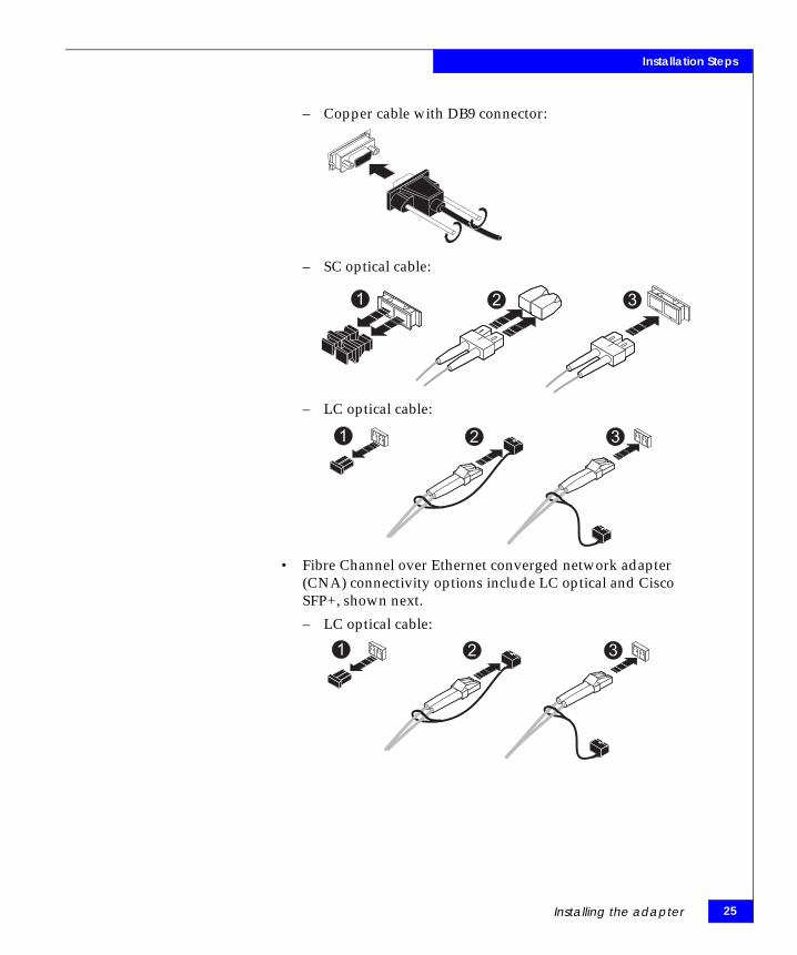
3. Plug one end of the cable into the connector on the adapter as shown in the appropriate figure under this step. (The hardware might be rotated 90 degrees clockwise from the orientation shown.)
• Fibre Channel adapter connectivity options include copper cable with DB9 connector, SC optical, and LC optical cable, as shown next.
EMC Host Connectivity with Brocade Fibre Channel HBAs and CNAs in the Linux Environment
Installation Steps
– Copper cable with DB9 connector:
– SC optical cable:
– LC optical cable:
• Fibre Channel over Ethernet converged network adapter (CNA) connectivity options include LC optical and Cisco SFP+, shown next.
– LC optical cable:
21 3
21 3
21 3
Installing the adapter 25

26
Installation Steps
– Cisco SFP+ (Twinax cable)
4. Plug the other end of the cable into a connector on the storage system or a hub/switch port. For FCoE switch connections, do not connect cables to the switch port until the switch has been properly configured.
5. Label each cable to identify the adapter and the storage/switch/hub port to which it connects.
6. Reapply power and allow the system to boot normally.
Matching the adapter with the correct PCI slot
When choosing an adapter for your server, it is important to know which adapter is compatible with your server's PCI/PCI-X/PCI Express slots. Certain adapter models have specific voltage requirements or physical limitations that allow them to work only in specific slots.
Servers have several different bus slot types for accepting adapters:
◆ PCI◆ PCI-X◆ PCI-X 2.0◆ PCI-Express
PCI slots can be 32-bit and 64-bit (denoted by their 124-pin or 188-pin connectors.) These slots have plastic "keys" that prevent certain adapters from fitting into them. These keys work with the cutout notches in the adapter edge connector so only compatible adapters will fit into them. This is done because of the voltage characteristics
EMC Host Connectivity with Brocade Fibre Channel HBAs and CNAs in the Linux Environment
Installation Steps
of the adapter. (For example, inserting a 3.3 V adapter into a 5 V slot will cause severe damage to both the adapter and the server.)
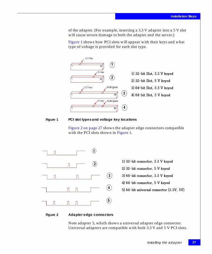
Figure 1 shows how PCI slots will appear with their keys and what type of voltage is provided for each slot type.
Figure 1 PCI slot types and voltage key locations
Figure 2 on page 27 shows the adapter edge connectors compatible with the PCI slots shown in Figure 1.
Figure 2 Adapter edge connectors
Note adapter 5, which shows a universal adapter edge connector. Universal adapters are compatible with both 3.3 V and 5 V PCI slots.
Installing the adapter 27
28
Installation Steps
PCI-X (or PCI Extended) slots increase the speed with which data travels over the bus. PCI-X slots appear identical to a 64-bit PCI slot keyed for 3.3 V. (Refer to number 3 in Figure 1 on page 27 and Figure 2.) PCI-X slots are backwards compatible with 3.3 V PCI adapters and universal adapters. Inserting standard PCI adapters into PCI-X slots will lower the bus speed as they cannot take advantage of the improved performance.
PCI-X 2.0 is the next generation of PCI-X buses. PCI-X 2.0 increases the bus speed again, providing more performance for adapters. PCI-X 2.0 slots also appear identical to a 64-bit PCI slot keyed for 3.3 V. (Refer to number 3 in Figure 1 on page 27 and Figure 2.) PCI-X 2.0 is also fully backward compatible with 3.3 V PCI and PCI-X.
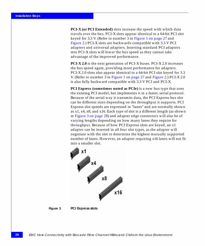
PCI Express (sometimes noted as PCIe) is a new bus type that uses the existing PCI model, but implements it in a faster, serial protocol. Because of the serial way it transmits data, the PCI Express bus slot can be different sizes depending on the throughput it supports. PCI Express slot speeds are expressed in "lanes" and are normally shown as x1, x4, x8, and x16. Each type of slot is a different length (as shown in Figure 3 on page 28) and adapter edge connectors will also be of varying lengths depending on how many lanes they require for throughput. Because of how PCI Express slots are keyed, an x1 adapter can be inserted in all four slot types, as the adapter will negotiate with the slot to determine the highest mutually supported number of lanes. However, an adapter requiring x16 lanes will not fit into a smaller slot.
Figure 3 PCI Express slots
EMC Host Connectivity with Brocade Fibre Channel HBAs and CNAs in the Linux Environment

Installation Steps
Figure 4 shows x1, x4, and x16 lane slots aligned on a mainboard. You can see how the slots are keyed so that low-lane adapters can fit into larger slots.
Figure 4 PCI Express slots aligned
Table 3 shows each of the EMC-supported Brocade adapters, and their respective slot requirements. Be sure to consult both your server user guide and Brocade to ensure that the adapter you want to use is compatible with your server's bus.
a. Gen1 (PCI Express Base Specification 1.0, 1.01a, 1.1), effective data rate is 16 Gb/s.
b. Gen2 (PCI Express Base Specification 2.0), effective data rate is 32 Gb/s.
Always refer to the EMC Support Matrix for the most up-to-date information on which servers support these adapters.
Table 3 Slot requirements of EMC-supported Brocade adapters
Adapter model Protocol PCI spec BUS length Power
Brocade 415 FC PCI ExpressGen1a , Gen2b
x8 lane 3.3V
Brocade 425 FC PCI ExpressGen1a , Gen2b
x8 lane 3.3V, 5V
Brocade 815 FC PCI ExpressGen1a , Gen2b
x8 lane 3.3V
Brocade 825 FC PCI ExpressGen1a , Gen2b
x8 lane 3.3V, 5V
Brocade 1010 FCoE PCI ExpressGen1a , Gen2b
x8 lane 3.3V
Brocade 1020 FCoE PCI ExpressGen1a , Gen2b
x8 lane 3.3V
Installing the adapter 29

30
Installation Steps
EMC Host Connectivity with Brocade Fibre Channel HBAs and CNAs in the Linux Environment

3Invisible Body Tag
This chapter provides information on installing and configuring the BIOS settings..
Note: Review the EMC Support Matrix for the latest information on approved adapters and drivers.
◆ Booting from an external storage array .......................................... 32◆ Installing/updating the Brocade adapter boot BIOS using the
LiveCD................................................................................................. 34◆ Configuring Brocade BIOS for array-based boot .......................... 36
Installing andConfiguring the BIOS
Settings
Installing and Configuring the BIOS Settings 31

32
Installing and Configuring the BIOS Settings
Booting from an external storage arrayBrocade’s software release 1.1 and later supports booting the system from a device on an external storage array. This boot device is a Logical Unit Number (LUN) located on the external storage array. The adapter boot code loads from Brocade adapter memory into system memory and integrates with the host system (server) BIOS during system boot to facilitate booting from array-based LUNs.
The Brocade adapter boot code supports the following host platform environments:
◆ PCI BIOS 2.1 and above, PCI firmware 3.0
Boot code for PCI system
◆ BIOS
Boot code for x86 and x64 platforms
◆ Unified Extensible Firmware Interface (UEFI)
Boot code for UEFI systems
This section provides the following information when booting from an external storage array:
◆ “Verifying the correct BIOS version,” next
◆ “Updating the boot BIOS” on page 33
Verifying the correct BIOS version
You can determine the BIOS version at boot time from the Brocade Banner, which displays during Power-On Self Test (POST) when the system is booted.
◆ If the banner does not display a BIOS, install the BIOS as described in “Installing/updating the Brocade adapter boot BIOS using the LiveCD” on page 34.
◆ If the banner displays the wrong BIOS version,Update the BIOS as described in “Configuring Brocade BIOS for array-based boot” on page 36.
EMC Host Connectivity with Brocade Fibre Channel HBAs and CNAs in the Linux Environment

Installing and Configuring the BIOS Settings
Updating the boot BIOSEither of the following three methods can be used to update the boot BIOS:
◆ “Installing/updating the Brocade adapter boot BIOS using the LiveCD” on page 34
◆ “Configuring Brocade BIOS for array-based boot” on page 36
Booting from an external storage array 33
34
Installing and Configuring the BIOS Settings
Installing/updating the Brocade adapter boot BIOS using the LiveCD
To install or update the Brocade adapter boot BIOS using the LiveCD, complete the following steps.
1. Obtain the latest LiveCD ISO image from the EMC-supported section of the Brocade website at http://www.brocade.com.
2. Create a CD from this image.
3. Boot the server from the CD.
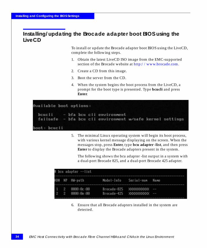
4. When the system begins the boot process from the LiveCD, a prompt for the boot type is presented. Type bcucli and press Enter.
5. The minimal Linux operating system will begin its boot process, with various kernel message displaying on the screen. When the messages stop, press Enter, type bcu adapter -list, and then press Enter to display the Brocade adapters present in the system.
The following shows the bcu adapter -list output in a system with a dual-port Brocade 825, and a dual-port Brocade 425 adapter.
6. Ensure that all Brocade adapters installed in the system are detected.
EMC Host Connectivity with Brocade Fibre Channel HBAs and CNAs in the Linux Environment

Installing and Configuring the BIOS Settings
7. Upload the boot BIOS code to the adapter(s) installed in the system. Type bcu boot --upload bfa_boot_fw -a and press Enter.
8. After the utility completes, reboot the system as instructed.
Installing/updating the Brocade adapter boot BIOS using the LiveCD 35

36
Installing and Configuring the BIOS Settings
Configuring Brocade BIOS for array-based bootThe Brocade BIOS Configuration Utility allows you to perform the following operations on selected adapters:
◆ Enable or disable BIOS to support boot over SAN.
• You must enable BIOS to support boot over SAN for an adapter port. If disabled, the host system cannot boot from array-based LUNs attached to the Brocade adapter(s).
• The default setting for the adapter boot BIOS is enabled on all adapter ports.
◆ Enable one of the following boot options:
• Auto DiscoverHost boots from LUN information provided by the fabric.
• Flash Values
Host boots from LUN information stored in flash memory.
• First LUN
Host boots from the first visible LUN.
◆ Select boot LUNs from discovered targets.
◆ Review adapter properties, such as the following:
• Port speed
• PWWN
• NWNN
• BIOS version
The Brocade adapter BIOS configuration menu is accessed during Power-On Self Test (POST) when the system is booted.
To configure the Brocade adapter boot BIOS settings using the BIOS configuration menu, complete the following steps.
1. Boot the system.
EMC Host Connectivity with Brocade Fibre Channel HBAs and CNAs in the Linux Environment
Installing and Configuring the BIOS Settings
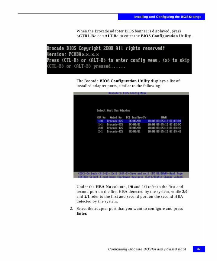
When the Brocade adapter BIOS banner is displayed, press <CTRL-B> or <ALT-B> to enter the BIOS Configuration Utility.
The Brocade BIOS Configuration Utility displays a list of installed adapter ports, similar to the following.
Under the HBA No column, 1/0 and 1/1 refer to the first and second port on the first HBA detected by the system, while 2/0 and 2/1 refer to the first and second port on the second HBA detected by the system.
2. Select the adapter port that you want to configure and press Enter.
Configuring Brocade BIOS for array-based boot 37
38
Installing and Configuring the BIOS Settings
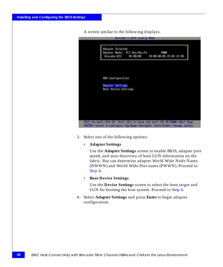
A screen similar to the following displays.
3. Select one of the following options:
• Adapter Settings
Use the Adapter Settings screen to enable BIOS, adapter port speed, and auto discovery of boot LUN information on the fabric. You can determine adapter World Wide Node Name (NWWN) and World Wide Port name (PWWN). Proceed to Step 4.
• Boot Device Settings
Use the Device Settings screen to select the boot target and LUN for booting the host system. Proceed to Step 6.
4. Select Adapter Settings and press Enter to begin adapter configuration.
EMC Host Connectivity with Brocade Fibre Channel HBAs and CNAs in the Linux Environment
Installing and Configuring the BIOS Settings
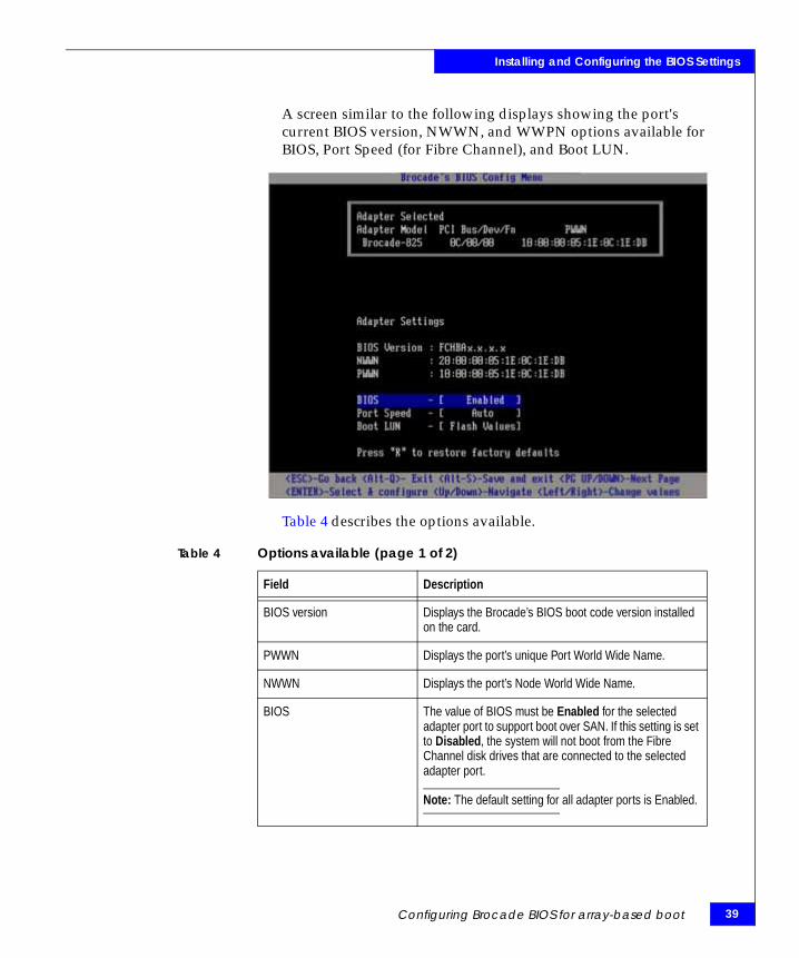
A screen similar to the following displays showing the port's current BIOS version, NWWN, and WWPN options available for BIOS, Port Speed (for Fibre Channel), and Boot LUN.
Table 4 describes the options available.
Table 4 Options available (page 1 of 2)
Field Description
BIOS version Displays the Brocade’s BIOS boot code version installed on the card.
PWWN Displays the port’s unique Port World Wide Name.
NWWN Displays the port’s Node World Wide Name.
BIOS The value of BIOS must be Enabled for the selected adapter port to support boot over SAN. If this setting is set to Disabled, the system will not boot from the Fibre Channel disk drives that are connected to the selected adapter port.
Note: The default setting for all adapter ports is Enabled.
Configuring Brocade BIOS for array-based boot 39

40
Installing and Configuring the BIOS Settings
The BIOS, Port speed, and Boot LUN settings can be modified. Use the following keys to select and change information:
• Up or Down — Scroll to a different field.• Enter — Select a field and configure values• Left and Right — Change a value in the selected field• Alt-S — Save configuration values to adapter flash memory• Alt-Q — Exit the BIOS configuration utility• <ESC> — Go to preceding page• PageUp or PageDown — Go to proceeding or next screen,
respectively
5. To configure boot devices, select Boot Device Settings from the menu described in Step 2, and press Enter.
Port speed (for Fibre Channel) Set the Fibre Channel link speed for adapter port:• Set Auto, 2, 4, or 8 for 815 and 825 adapters.• Set Auto, 1, 2, or 4 for 415 and 425 adapters.Auto allows adapter the port to automatically negotiate link speed with the connected port.
Boot LUN • Auto Discover. When enabled, LUN information, such as the location of boot LUN, is provided by the fabric (refer to “Fabric based boot LUN discovery” on page 35).
• Flash Values. Boot LUN information will be obtained from flash memory. Note that values are saved to flash when you configure and save them through the BIOS Configuration Utility and BCU.
• First LUN. The host boots from the first LUN visible to the adapter that is discovered in the fabric.
Table 4 Options available (page 2 of 2)
Field Description
EMC Host Connectivity with Brocade Fibre Channel HBAs and CNAs in the Linux Environment
Installing and Configuring the BIOS Settings
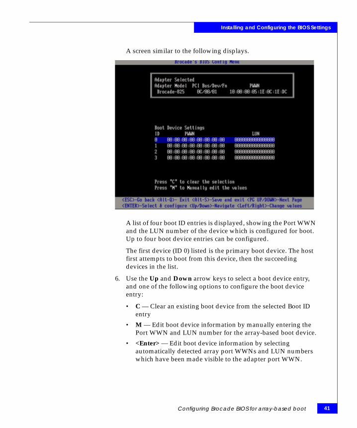
A screen similar to the following displays.
A list of four boot ID entries is displayed, showing the Port WWN and the LUN number of the device which is configured for boot. Up to four boot device entries can be configured.
The first device (ID 0) listed is the primary boot device. The host first attempts to boot from this device, then the succeeding devices in the list.
6. Use the Up and Down arrow keys to select a boot device entry, and one of the following options to configure the boot device entry:
• C — Clear an existing boot device from the selected Boot ID entry
• M — Edit boot device information by manually entering the Port WWN and LUN number for the array-based boot device.
• <Enter> — Edit boot device information by selecting automatically detected array port WWNs and LUN numbers which have been made visible to the adapter port WWN.
Configuring Brocade BIOS for array-based boot 41
42
Installing and Configuring the BIOS Settings
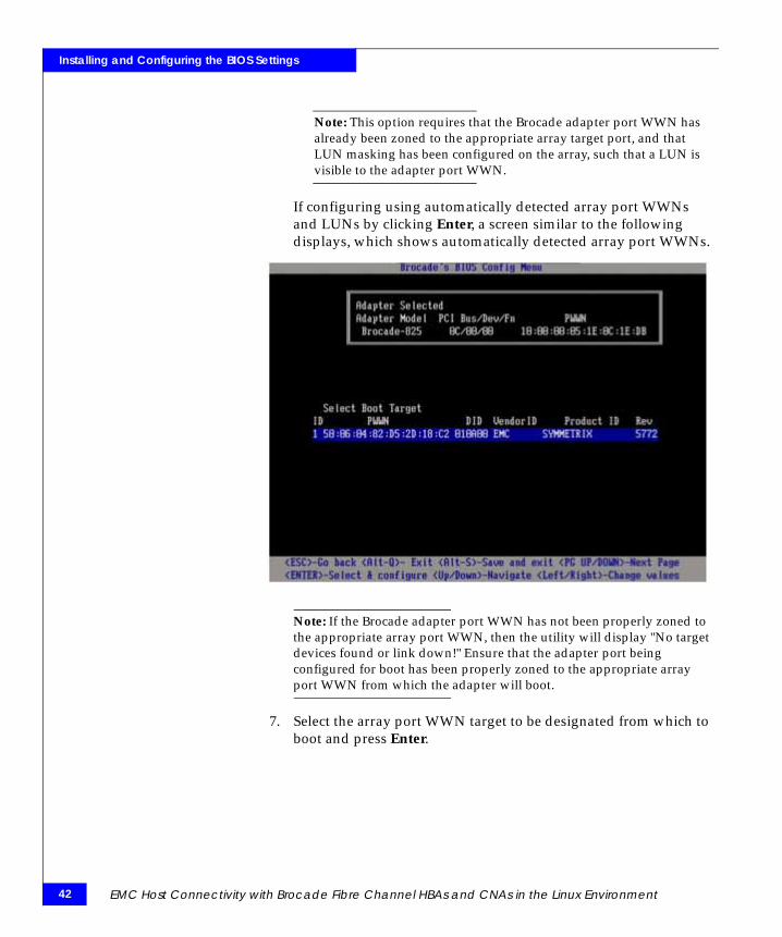
Note: This option requires that the Brocade adapter port WWN has already been zoned to the appropriate array target port, and that LUN masking has been configured on the array, such that a LUN is visible to the adapter port WWN.
If configuring using automatically detected array port WWNs and LUNs by clicking Enter, a screen similar to the following displays, which shows automatically detected array port WWNs.
Note: If the Brocade adapter port WWN has not been properly zoned to the appropriate array port WWN, then the utility will display "No target devices found or link down!" Ensure that the adapter port being configured for boot has been properly zoned to the appropriate array port WWN from which the adapter will boot.
7. Select the array port WWN target to be designated from which to boot and press Enter.
EMC Host Connectivity with Brocade Fibre Channel HBAs and CNAs in the Linux Environment
Installing and Configuring the BIOS Settings
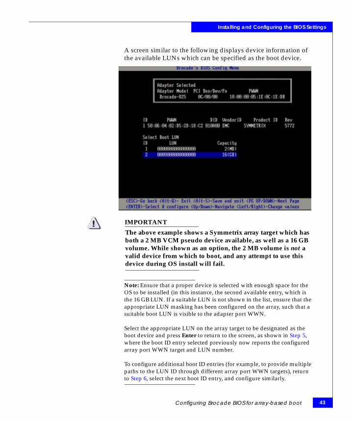
A screen similar to the following displays device information of the available LUNs which can be specified as the boot device.
IMPORTANT!The above example shows a Symmetrix array target which has both a 2 MB VCM pseudo device available, as well as a 16 GB volume. While shown as an option, the 2 MB volume is not a valid device from which to boot, and any attempt to use this device during OS install will fail.
Note: Ensure that a proper device is selected with enough space for the OS to be installed (in this instance, the second available entry, which is the 16 GB LUN. If a suitable LUN is not shown in the list, ensure that the appropriate LUN masking has been configured on the array, such that a suitable boot LUN is visible to the adapter port WWN.
Select the appropriate LUN on the array target to be designated as the boot device and press Enter to return to the screen, as shown in Step 5, where the boot ID entry selected previously now reports the configured array port WWN target and LUN number.
To configure additional boot ID entries (for example, to provide multiple paths to the LUN ID through different array port WWN targets), return to Step 6, select the next boot ID entry, and configure similarly.
Configuring Brocade BIOS for array-based boot 43
44
Installing and Configuring the BIOS Settings
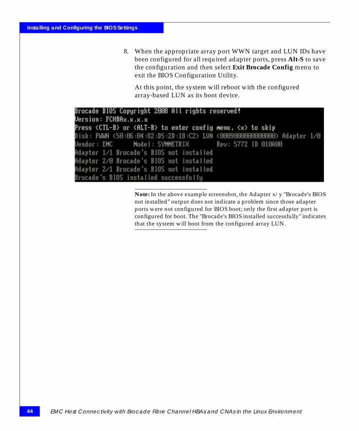
8. When the appropriate array port WWN target and LUN IDs have been configured for all required adapter ports, press Alt-S to save the configuration and then select Exit Brocade Config menu to exit the BIOS Configuration Utility.
At this point, the system will reboot with the configured array-based LUN as its boot device.
Note: In the above example screenshot, the Adapter x/y "Brocade's BIOS not installed" output does not indicate a problem since those adapter ports were not configured for BIOS boot; only the first adapter port is configured for boot. The "Brocade's BIOS installed successfully" indicates that the system will boot from the configured array LUN.
EMC Host Connectivity with Brocade Fibre Channel HBAs and CNAs in the Linux Environment

4Invisible Body Tag
This chapter describes the procedures for installing and configuring a Brocade driver in a Linux Host.
Note: Review the EMC Support Matrix for the latest information on approved adapters and drivers.
◆ Installing the Brocade in-kernel driver ........................................... 46◆ Installing the Brocade out-of-kernel driver.................................... 47
Installing andConfiguring a Brocade
Driver in a Linux Host
Installing and Configuring a Brocade Driver in a Linux Host 45
46
Installing and Configuring a Brocade Driver in a Linux Host
Installing the Brocade in-kernel driverFor the Brocade HBA/CNA to function normally, it is important that the host to have the correct EMC-supported Brocade drivers. Refer to the latest EMC Support Matrix for the most up-today information on drivers.
Installation to a local boot disk or an array-based disk using in-kernel driver
If installing RHEL or SLES to a locally-attached disk drive (such as internal SCSI or SATA RAID controller), or/and an array-based disk visible through the Brocade adapter, no additional steps are required during the install process.
If the Brocade adapter driver is not included in the current RHEL or SLES Linux distributions, the driver must be manually installed after the installation of the OS. For more details, refer to “Installing an out-of-kernel driver and software utilities on a locally attached disk” on page 47.
If the driver is out-of-kernel and the OS is to be installed on an array-based BOOT disk, a Driver Update Disk (DUD) must be loaded during the OS installation. For more details, refer to “Installation to an array-based disk connected to the Brocade adapter with an out-of-kernel driver” on page 54.
EMC Host Connectivity with Brocade Fibre Channel HBAs and CNAs in the Linux Environment

Installing and Configuring a Brocade Driver in a Linux Host
Installing the Brocade out-of-kernel driverFor the Brocade HBA/CNA to function normally, it is important that the host to have the correct EMC-supported Brocade drivers. Refer to the latest EMC Support Matrix for the most up-today information on drivers.
This section contains the following information for installing the Brocade out-of-kernel driver:
◆ “Installing an out-of-kernel driver and software utilities on a locally attached disk” on page 47
◆ “Installation to an array-based disk connected to the Brocade adapter with an out-of-kernel driver” on page 54
◆ “RHEL OS installation to an array-based disk with an out-of-kernel driver” on page 54
◆ “SLES 9 OS installation to an array-based disk with an out-of-kernel driver” on page 55
◆ “SLES 10 or SLES 11OS installation to an array-based disk with an out-of-kernel driver” on page 56
Installing an out-of-kernel driver and software utilities on a locally attached diskWith the Linux OS installed to a local disk, and the Brocade adapter installed in the system, use the Brocade HBA Software Installer to selectively install the Brocade HBA driver, Host Connectivity Manager (HCM) software package to manage and/or configure the Brocade HBA and/or the HCM agent (allowing another system to remotely manage and/or configure the Brocade HBA).
This section reviews the installation of a Brocade HBA driver and software utilities using the GUI-based Brocade HBA Software Installer.
Installing the Brocade out-of-kernel driver 47
48
Installing and Configuring a Brocade Driver in a Linux Host
Using the BrocadeHBA Software Installer
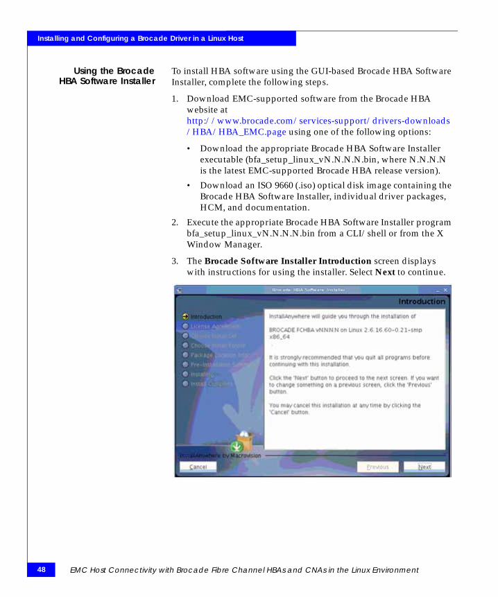
To install HBA software using the GUI-based Brocade HBA Software Installer, complete the following steps.
1. Download EMC-supported software from the Brocade HBA website at http://www.brocade.com/services-support/drivers-downloads/HBA/HBA_EMC.page using one of the following options:
• Download the appropriate Brocade HBA Software Installer executable (bfa_setup_linux_vN.N.N.N.bin, where N.N.N.N is the latest EMC-supported Brocade HBA release version).
• Download an ISO 9660 (.iso) optical disk image containing the Brocade HBA Software Installer, individual driver packages, HCM, and documentation.
2. Execute the appropriate Brocade HBA Software Installer program bfa_setup_linux_vN.N.N.N.bin from a CLI/shell or from the X Window Manager.
3. The Brocade Software Installer Introduction screen displays with instructions for using the installer. Select Next to continue.
EMC Host Connectivity with Brocade Fibre Channel HBAs and CNAs in the Linux Environment
Installing and Configuring a Brocade Driver in a Linux Host
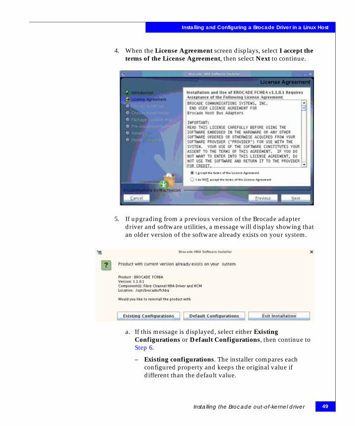
4. When the License Agreement screen displays, select I accept the terms of the License Agreement, then select Next to continue.
5. If upgrading from a previous version of the Brocade adapter driver and software utilities, a message will display showing that an older version of the software already exists on your system.
a. If this message is displayed, select either Existing Configurations or Default Configurations, then continue to Step 6.
– Existing configurations. The installer compares each configured property and keeps the original value if different than the default value.
Installing the Brocade out-of-kernel driver 49

50
Installing and Configuring a Brocade Driver in a Linux Host
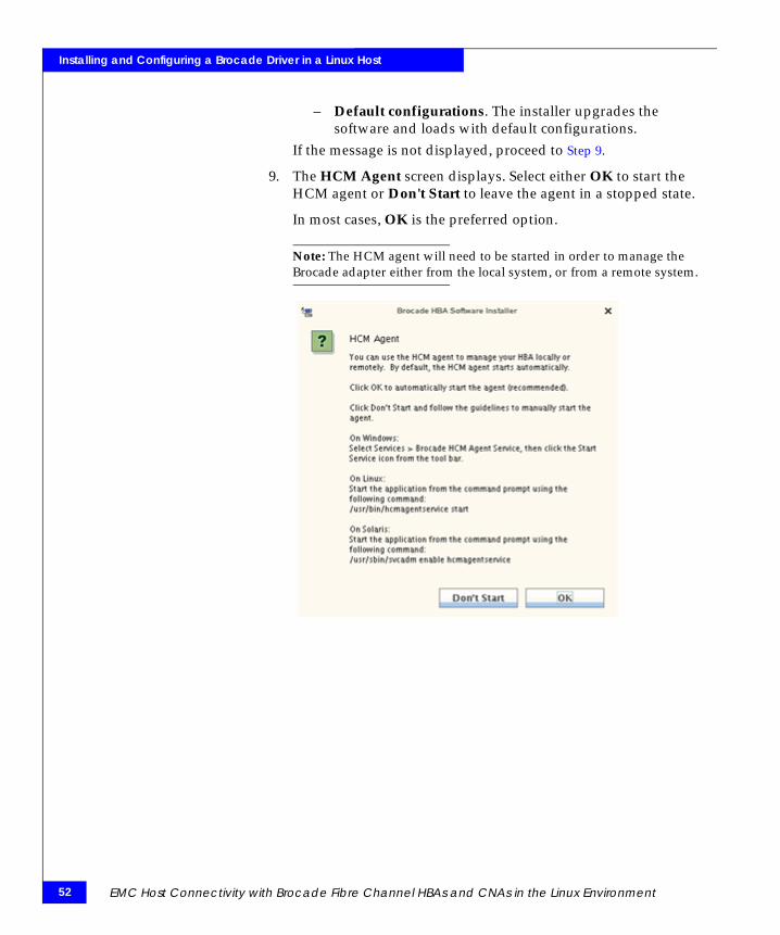
– Default configurations. The installer upgrades the software and loads with default configurations
b. If this message is not displayed, continue to Step 6.
6. When the Choose Install Set screen is displayed, select which software you want to install, then select Next.
Note: The Choose Install Set and Choose Install Folder will not be displayed if upgrading from an older version of the software. If this is the case, continue to Step 9.
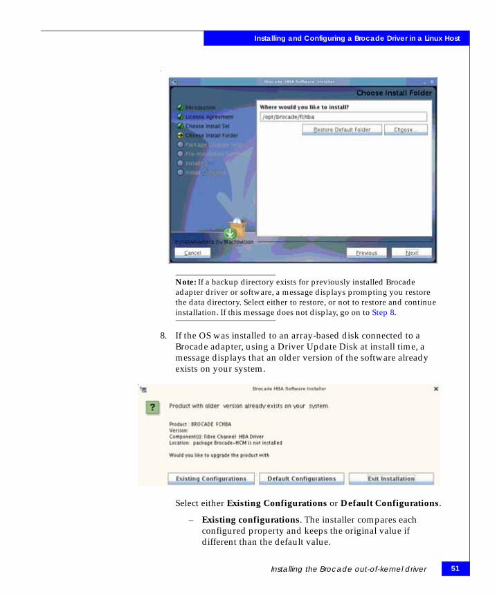
7. If not upgrading from a previous version of the software, the installation prompts for the location to install the Brocade adapter driver and software utilities.
If desired, select Restore Default Folder to enter the default installation folder, or Choose to browse to another location on the system.
Select Next to continue.
EMC Host Connectivity with Brocade Fibre Channel HBAs and CNAs in the Linux Environment
Installing and Configuring a Brocade Driver in a Linux Host
.
Note: If a backup directory exists for previously installed Brocade adapter driver or software, a message displays prompting you restore the data directory. Select either to restore, or not to restore and continue installation. If this message does not display, go on to Step 8.
8. If the OS was installed to an array-based disk connected to a Brocade adapter, using a Driver Update Disk at install time, a message displays that an older version of the software already exists on your system.
Select either Existing Configurations or Default Configurations.
– Existing configurations. The installer compares each configured property and keeps the original value if different than the default value.
Installing the Brocade out-of-kernel driver 51
52
Installing and Configuring a Brocade Driver in a Linux Host
– Default configurations. The installer upgrades the software and loads with default configurations.
If the message is not displayed, proceed to Step 9.
9. The HCM Agent screen displays. Select either OK to start the HCM agent or Don't Start to leave the agent in a stopped state.
In most cases, OK is the preferred option.
Note: The HCM agent will need to be started in order to manage the Brocade adapter either from the local system, or from a remote system.
EMC Host Connectivity with Brocade Fibre Channel HBAs and CNAs in the Linux Environment
Installing and Configuring a Brocade Driver in a Linux Host
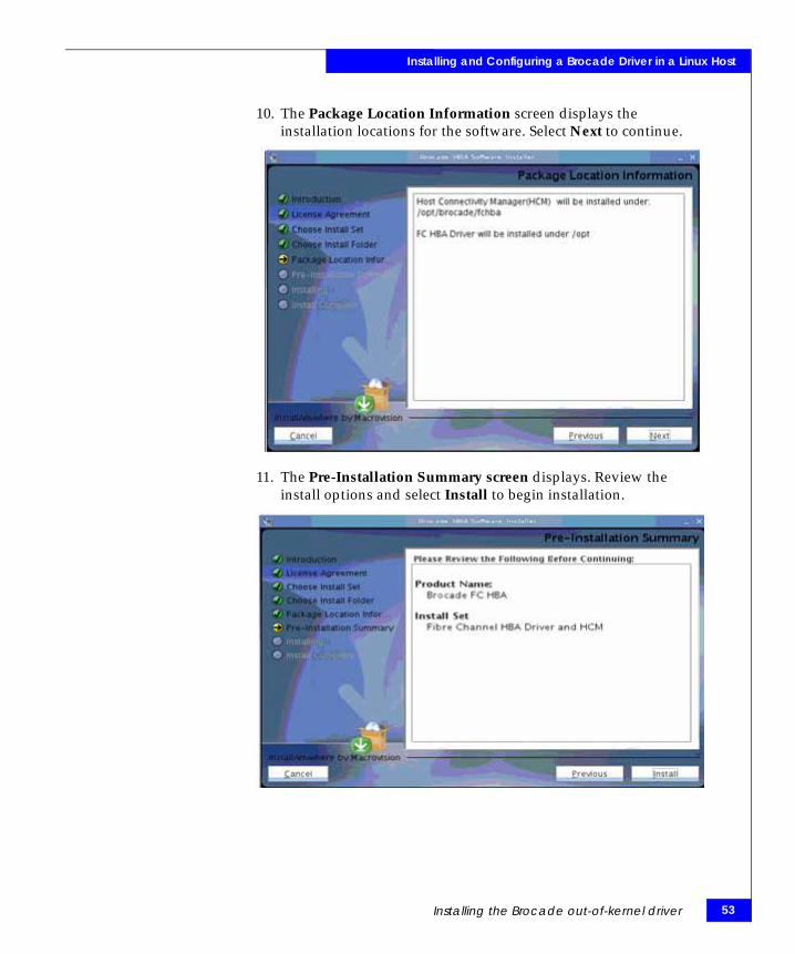
10. The Package Location Information screen displays the installation locations for the software. Select Next to continue.
11. The Pre-Installation Summary screen displays. Review the install options and select Install to begin installation.
Installing the Brocade out-of-kernel driver 53
54
Installing and Configuring a Brocade Driver in a Linux Host
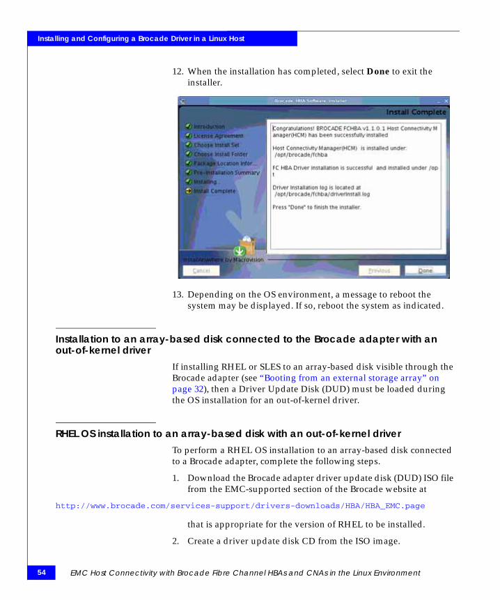
12. When the installation has completed, select Done to exit the installer.
13. Depending on the OS environment, a message to reboot the system may be displayed. If so, reboot the system as indicated.
Installation to an array-based disk connected to the Brocade adapter with an out-of-kernel driver
If installing RHEL or SLES to an array-based disk visible through the Brocade adapter (see “Booting from an external storage array” on page 32), then a Driver Update Disk (DUD) must be loaded during the OS installation for an out-of-kernel driver.
RHEL OS installation to an array-based disk with an out-of-kernel driverTo perform a RHEL OS installation to an array-based disk connected to a Brocade adapter, complete the following steps.
1. Download the Brocade adapter driver update disk (DUD) ISO file from the EMC-supported section of the Brocade website at
http://www.brocade.com/services-support/drivers-downloads/HBA/HBA_EMC.page
that is appropriate for the version of RHEL to be installed.
2. Create a driver update disk CD from the ISO image.
EMC Host Connectivity with Brocade Fibre Channel HBAs and CNAs in the Linux Environment

Installing and Configuring a Brocade Driver in a Linux Host
3. Insert the RHEL product CD #1 or DVD in the CD/DVD drive and boot the system.
4. At the Linux boot: prompt, type linux dd and press Enter.
5. When the Driver Disk message box displays “Do you have a driver disk,” select Yes, then press Enter.
Note: You must load the Brocade adapter driver at this stage so that the system can access the boot LUN for Linux installation.
6. From the Driver Disk Source window, select the driver source hdx (where x is the CD/DVD drive letter), then press Enter.
The Insert Driver Disk window displays.
7. Insert the driver update disk that you created in Step 2 into the CD or DVD drive. Select OK, then press Enter.
The driver loads automatically.
8. When the Disk Driver window prompts for more drivers to install, select No, then press Enter.
9. Insert the Linux Red Hat product CD #1 or DVD in the CD/DVD drive (remove the adapter driver update CD first if necessary), then press Enter.
10. Continue responding to on-screen instructions and refer to your system documentation as necessary to format and complete installation on the array-based target boot LUN.
SLES 9 OS installation to an array-based disk with an out-of-kernel driverTo perform a SLES 9 OS installation to an array-based disk connected to a Brocade adapter, complete the following steps.
1. Download the Brocade adapter driver update disk (DUD) ISO file from the EMC-supported section of the Brocade website at
http://www.brocade.com/services-support/drivers-downloads/HBA/HBA_EMC.page
that is appropriate for SLES 9.
2. Create a driver update disk CD from the ISO image.
3. Insert the SLES product CD #1 or DVD in the CD/DVD drive and boot the system.
Installing the Brocade out-of-kernel driver 55

56
Installing and Configuring a Brocade Driver in a Linux Host
4. When the main installation screen displays, press F6 to load the driver.
A message displays to get your driver update floppy/CD ready.
5. Select the Installation option, then press Enter.
A message displays to insert the driver update floppy/CDROM.
Note: You must load the Brocade adapter driver at this stage so that the system can access the boot LUN for Linux installation.
6. Replace the SLES product CD with the driver update disk that you created in Step 2.
7. Continue responding to on-screen instructions and refer to your system documentation as necessary to format and complete installation on the target boot LUN.
SLES 10 or SLES 11OS installation to an array-based disk with an out-of-kernel driver
To perform a SLES 10 or SLES 11 OS installation to an array-based disk connected to a Brocade adapter, complete the following steps.
1. Download the Brocade adapter driver update disk (DUD) ISO file from the EMC-supported section of the Brocade website at
http://www.brocade.com/services-support/drivers-downloads/HBA/HBA_EMC.page
that is appropriate for SLES 10 or SLES 11.
2. Create a driver update disk CD from the ISO image.
3. Insert the SLES product CD #1 or DVD in the CD/DVD drive and boot the system.
4. When the main installation screen displays, press F6 to load the driver.
5. The system prompts to select Yes, No, or File. Select Yes, and press Enter.
6. When the "Please choose the driver update medium" prompt displays, replace the SLES product CD/DVD with the SLES driver update disk that you created in Step 2.
EMC Host Connectivity with Brocade Fibre Channel HBAs and CNAs in the Linux Environment

Installing and Configuring a Brocade Driver in a Linux Host
Note: You must load the Brocade adapter driver at this stage so that the system can access the boot LUN for Linux installation.
7. Select CD drive (hdx, where x is the CD/DVD drive letter) then press Enter.
The driver update loads to the system.
8. If the driver update was successful, a "Driver Update OK" message displays. Press Enter.
9. If the system prompts you to update another driver, select BACK, then press Enter.
10. When the “Make sure that CD number 1” message displays, insert the SLES product CD #1 or DVD into the CD/DVD drive and select OK.
11. Continue responding to on-screen instructions and refer to your system documentation as necessary to format and complete installation on the target boot LUN.
Installing the Brocade out-of-kernel driver 57

58
Installing and Configuring a Brocade Driver in a Linux Host
EMC Host Connectivity with Brocade Fibre Channel HBAs and CNAs in the Linux Environment

5Invisible Body Tag
This chapter contains information on connecting to the storage array.
◆ Zoning in a fabric environment ............................................................. 60◆ Establishing connectivity to the storage array..................................... 61◆ Verifying connectivity through Brocade HCM.................................... 62
Connecting to theStorage Array
Connecting to the Storage Array 59

60
Connecting to the Storage Array
Zoning in a fabric environmentIn a fabric environment, the user should plan for the switch topology, target-to-hosts mapping, and the zone. The following is an overview of the recommended procedure:
1. Draw the connectivity among the hosts, switch, and storage array to verify the correct fabric configuration.
2. Configure the zone capability in the switch. If connecting to EMC Connectrix™, refer to the Connectrix Enterprise Storage Network System Planning Guide for information on the zone configuration.
EMC Host Connectivity with Brocade Fibre Channel HBAs and CNAs in the Linux Environment

Connecting to the Storage Array
Establishing connectivity to the storage arrayOnce the adapter has been properly configured, connectivity will need to be established between the adapter and the storage array. In the case, where the adapter will be directly connected to the storage array, the cable can just be attached. However, when attaching to an FC or FCoE switch, several additional configuration steps are needed.
These include zoning the port on the adapter to the correct port on the storage array, as well as configuring LUN Masking on the array.
For additional information on how to perform these additional installation steps, refer to the EMC Host Connectivity Guide for Linux, located at http://elabnavigator.EMC.com.
Note: You will need to reload the driver or reboot the server so the new targets and LUNs may be scanned and acquired by the Linux SCSI subsystem.
Establishing connectivity to the storage array 61
62
Connecting to the Storage Array
Verifying connectivity through Brocade HCMTo verify connectivity through Brocade Host Connectivity Manager (HCM), complete the following steps.
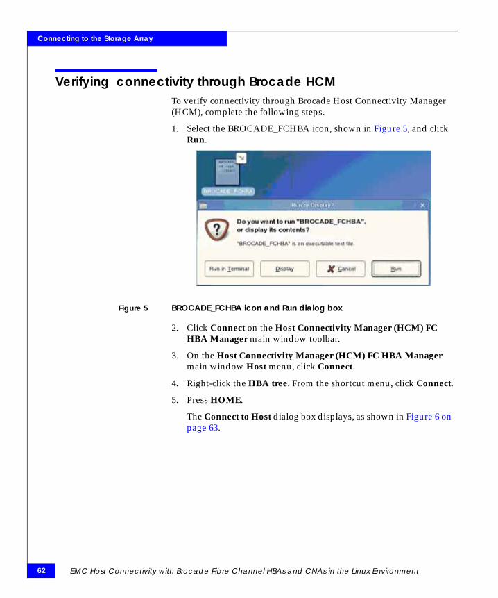
1. Select the BROCADE_FCHBA icon, shown in Figure 5, and click Run.
Figure 5 BROCADE_FCHBA icon and Run dialog box
2. Click Connect on the Host Connectivity Manager (HCM) FC HBA Manager main window toolbar.
3. On the Host Connectivity Manager (HCM) FC HBA Manager main window Host menu, click Connect.
4. Right-click the HBA tree. From the shortcut menu, click Connect.
5. Press HOME.
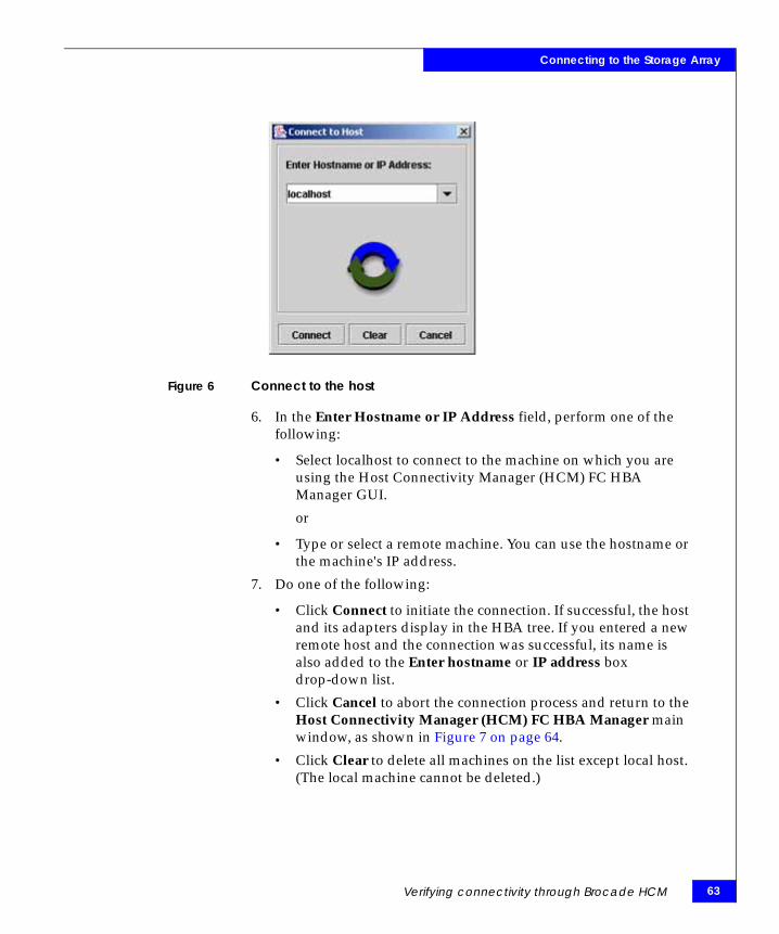
The Connect to Host dialog box displays, as shown in Figure 6 on page 63.
EMC Host Connectivity with Brocade Fibre Channel HBAs and CNAs in the Linux Environment
Connecting to the Storage Array
Figure 6 Connect to the host
6. In the Enter Hostname or IP Address field, perform one of the following:
• Select localhost to connect to the machine on which you are using the Host Connectivity Manager (HCM) FC HBA Manager GUI.
or
• Type or select a remote machine. You can use the hostname or the machine's IP address.
7. Do one of the following:
• Click Connect to initiate the connection. If successful, the host and its adapters display in the HBA tree. If you entered a new remote host and the connection was successful, its name is also added to the Enter hostname or IP address box drop-down list.
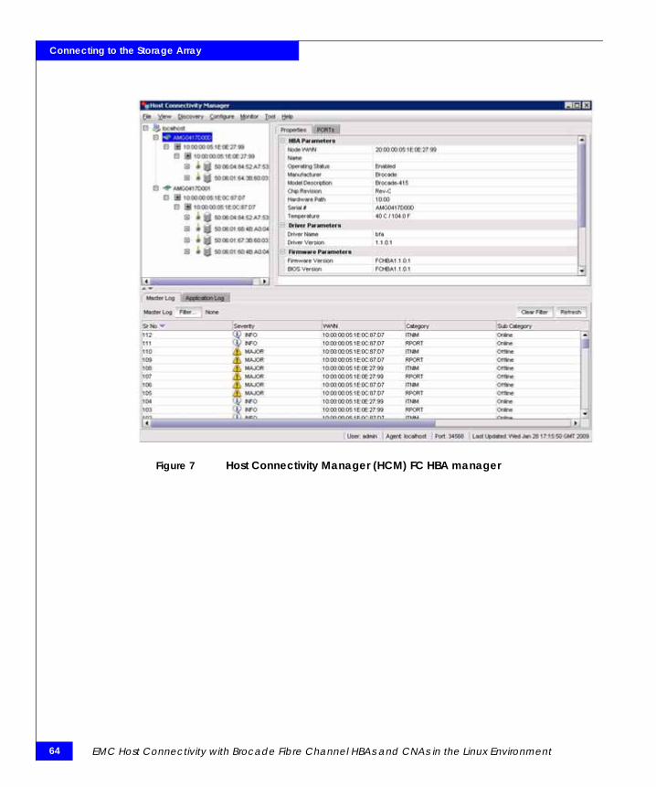
• Click Cancel to abort the connection process and return to the Host Connectivity Manager (HCM) FC HBA Manager main window, as shown in Figure 7 on page 64.
• Click Clear to delete all machines on the list except local host. (The local machine cannot be deleted.)
Verifying connectivity through Brocade HCM 63
64
Connecting to the Storage Array
Figure 7 Host Connectivity Manager (HCM) FC HBA manager
EMC Host Connectivity with Brocade Fibre Channel HBAs and CNAs in the Linux Environment

AInvisible Body Tag
This appendix contains additional information to consider.
◆ EMC-supported Brocade drivers for Linux ................................... 66◆ Linux device-naming convention.................................................... 68
Additional Notes
Additional Notes 65

66
Additional Notes
EMC-supported Brocade drivers for LinuxRefer to the EMC Support Matrix for the most up-to-date information on Brocade driver support.
Table 5 lists the EMC supported Brocade Linux in-kernel drivers.
Table 5 EMC supported Brocade Linux in-kernel drivers
Operating system In-kernel driver version
Supported adapters
4G FC EM- 415EM- 425
8G FC EM-815EM-825
CNAEM-1010EM-1020
RHEL 5.5 2.1.2.0
RHEL 5.6 2.1.2.2
RHEL 5.7 2.3.2.3
RHEL 6.0 2.1.2.1
RHEL 6.1 2.3.2.3
RHEL 6.2 3.0.2.2 (BFA)3.0.2.2r (BNA)
SLES 10 SP3 2.0.0.0
SLES 10 SP4 2.3.2.1
SLES 11 1.1.0.2
SLES 11 SP1 2.1.2.1
EMC Host Connectivity with Brocade Fibre Channel HBAs and CNAs in the Linux Environment
Additional Notes
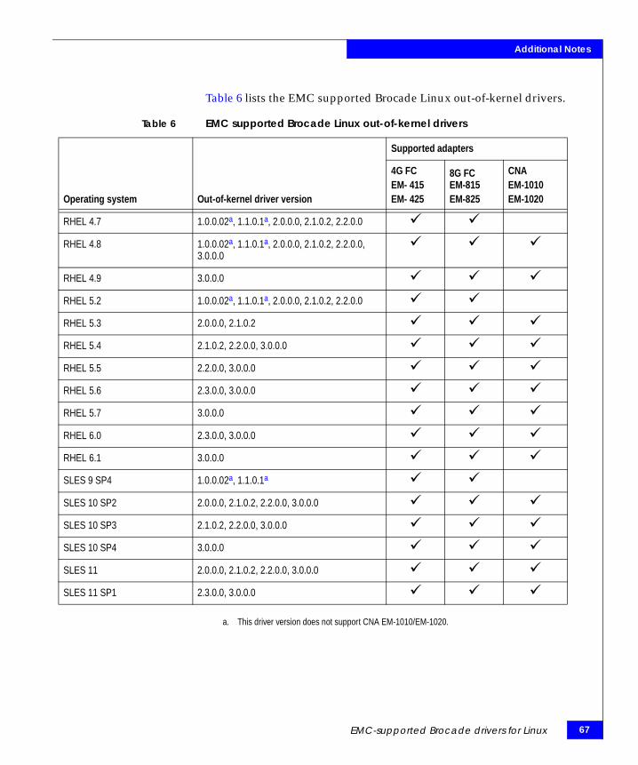
Table 6 lists the EMC supported Brocade Linux out-of-kernel drivers.
a. This driver version does not support CNA EM-1010/EM-1020.
Table 6 EMC supported Brocade Linux out-of-kernel drivers
Operating system Out-of-kernel driver version
Supported adapters
4G FC EM- 415EM- 425
8G FC EM-815EM-825
CNAEM-1010EM-1020
RHEL 4.7 1.0.0.02a, 1.1.0.1a, 2.0.0.0, 2.1.0.2, 2.2.0.0
RHEL 4.8 1.0.0.02a, 1.1.0.1a, 2.0.0.0, 2.1.0.2, 2.2.0.0, 3.0.0.0
RHEL 4.9 3.0.0.0
RHEL 5.2 1.0.0.02a, 1.1.0.1a, 2.0.0.0, 2.1.0.2, 2.2.0.0
RHEL 5.3 2.0.0.0, 2.1.0.2
RHEL 5.4 2.1.0.2, 2.2.0.0, 3.0.0.0
RHEL 5.5 2.2.0.0, 3.0.0.0
RHEL 5.6 2.3.0.0, 3.0.0.0
RHEL 5.7 3.0.0.0
RHEL 6.0 2.3.0.0, 3.0.0.0
RHEL 6.1 3.0.0.0
SLES 9 SP4 1.0.0.02a, 1.1.0.1a
SLES 10 SP2 2.0.0.0, 2.1.0.2, 2.2.0.0, 3.0.0.0
SLES 10 SP3 2.1.0.2, 2.2.0.0, 3.0.0.0
SLES 10 SP4 3.0.0.0
SLES 11 2.0.0.0, 2.1.0.2, 2.2.0.0, 3.0.0.0
SLES 11 SP1 2.3.0.0, 3.0.0.0
EMC-supported Brocade drivers for Linux 67
68
Additional Notes
Linux device-naming conventionThe four high-level device drivers in Linux are:
sd - Direct access (disks)sg - SCSI generic interfacesr - Data CD-ROMsst - Tapes
The sg driver is a character-based device while the other three drivers are block-based devices. The sg driver is used primarily for scanners, CD writers, and printers. The sg device files are dynamically mapped to SCSI IDs/LUNs on the SCSI bus starting with the first SCSI controller.
Block device file names
A native device file name for block devices takes the following form:
/dev/sdLN
where:
◆ L is a letter denoting the physical drive.and Configuring the HBA and Driver.
◆ N is a number denoting the partition on that physical drive.
Note: Usually, the partition number is not included when referring to the entire drive.
Following this format, the filenames are as follows:
/dev/sd[a-d][a-z][1-15]
The Linux kernel reserves 16 major numbers for SCSI devices. Each major number can have zero to 255 minor numbers. These minor numbers include the partitions for a SCSI device. Linux supports one to 15 partitions per disk device. Partitions 1 through 4 are the primary partitions, while partitions 5 and greater are the logical or extended partitions. These limitations are specific to the Intel platform. By default, slices are not used in Linux.
Therefore, the product of 16 major numbers and 16 minor numbers yields 256 SCSI devices. As a result, the kernel is able to scan logical devices ranging from 0 through 255. Red Hat Linux distributions and
EMC Host Connectivity with Brocade Fibre Channel HBAs and CNAs in the Linux Environment
Additional Notes
SuSE SLES 7 support a maximum of 128 SCSI devices as opposed to the SuSE SLES 8 distribution, which supports all 256 SCSI devices. The 256 total of SCSI devices includes any non-EMC storage array devices, such as local disks.
Red Hat distributions
Red Hat Linux distributions can scan LUN numbers from 0 through 255; however, only the first 128 SCSI devices discovered by the system will be mapped to an sd device. Any gaps in devices presented to the system will not result in gaps in the sd device names.
Note: The first device may be a non-zero LUN.
Examples:
◆ If you have allocated devices 0 through 255 to the Linux host, it will be able to scan up to 255; however, only the first 128 devices (0 through 127) will be usable and accessible by the host.
◆ If you have LUNs 128 through 255 assigned to a Linux host, you will be able to scan through and use all of them.
◆ If you have LUNs 256 or above exported to a Linux host, the Linux hosts will neither see nor be able to access those devices with an address over 256.
In total, a Red Hat host could support disk devices from /dev/sda through /dev/sddx.
SuSE distributions
For SuSE distributions prior to SLES 8, the limitations are the same as for Red Hat distributions. SuSE SLES 8 is different in that it supports up to 256 devices by default as it reserves 16 major numbers for SCSI devices.
Each major number is allocated 0 to 255 minor numbers that are used to denote the partitions for a SCSI device. Therefore, a product of 16 major numbers and 16 minor numbers yields up to 256 SCSI devices. As a result, the kernel is able to scan logical devices ranging from 0 through 255. These disk devices would be reported as /dev/sda through /dev/sdiu.
Linux device-naming convention 69

70
Additional Notes
Therefore, if you have allocated LUNs from 0 through 255 to the SLES 8 Linux host, the host can scan and use all 256 logical units. However, just as with Red Hat distributions, if you present logical units over 256 to a Linux host, the host will neither see nor be able to access those devices with an address of over 256.
PowerPath examples
When EMC PowerPath® is installed, keep in mind that there is a limitation of 128 SCSI devices total per system, not per adapter.
◆ Example without PowerPath — If you have two HBAs or a dual channel HBA and you want both ports/HBAs to see and access devices; you must split the 128 devices between the two HBAs. For example, 64 devices would be allocated to each HBA. If you allocate 128 devices to the first HBA, the second HBA will not be able to access any devices. The limitation of 128 SCSI devices is in the Linux SCSI subsystem and is per system, not per adapter.
◆ Example with PowerPath — Keep in mind that if you present 128 LUNs to a Linux host to one HBA, then only that one HBA will be able to see and access devices.
In the case of PowerPath, if you have eight HBAs in a server and plan to have two paths per HBA, you will be left with only eight devices per HBA:
128 LUNs/ (8 HBAs * 2 paths) = 8 devices
EMC Host Connectivity with Brocade Fibre Channel HBAs and CNAs in the Linux Environment