san francisco – oakland bay bridge self-anchored...
TRANSCRIPT

San Francisco – Oakland Bay BridgeSELF-ANCHORED SUSPENSION (SAS) SPAN

22
• Project Overview• Conventional Vs SAS Bridge• SFOBB SAS Features• International Fabrication• Temporary Bridge• Shear Leg Crane• Concrete Works• Quality Program
– Audits– Quality Plans– Mock-ups and Pre-qualifications– NCR Processing– In-process Tests and Inspections– Weld Tracking
San Francisco – Oakland Bay BridgeSELF-ANCHORED SUSPENSION (SAS) SPAN

33
Project Overview

44
October 17, 1989

55
Current East Span

66
Replacement Span
150 Year Service Life
1400 Year Earthquake

77San Francisco-Oakland Bay Bridge (SFOBB)
Self-Anchored Suspension (SAS)
SAS
YBITransition
BID AMT $1.41BFirst Working Date May 18, 2006Estimated Completion Date Spring 2013
West Approach
West Span

88
Existing
View Driving West to San Francisco

99 Bicycle/Pedestrian Facility
1010
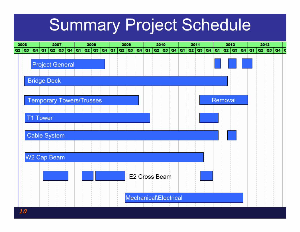
Removal
E2 Cross Beam
Project General
Bridge Deck
Temporary Towers/Trusses
T1 Tower
Cable System
W2 Cap Beam
Mechanical\Electrical
Summary Project Schedule
1111
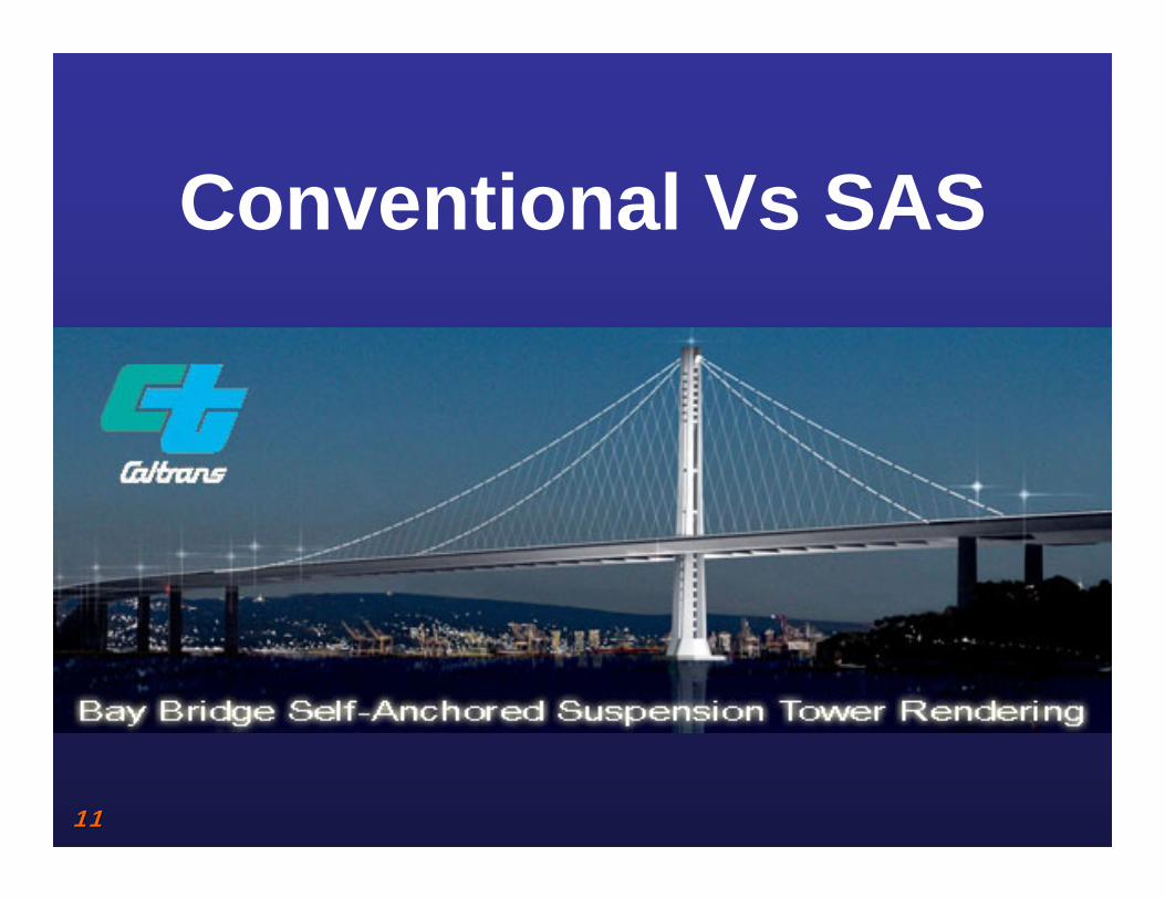
Conventional Vs SAS
1212
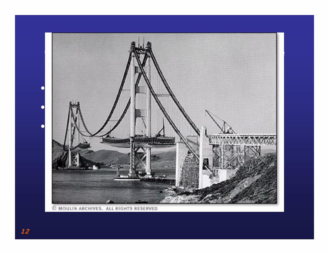
Conventional Suspension Bridge
• Two towers• Two Main cables anchored to land• Deck sections lifted in-place

1313
Self-Anchored Suspension
• Need to build a bridge to build the bridge
• Bridge deck acts as compression member
• Transfer of deck loads to cable is last structural operation performed
1414
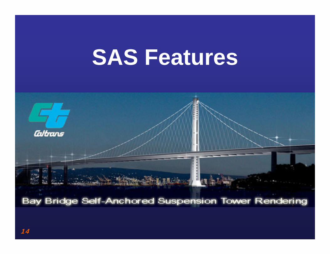
SAS Features

1515
SFOBB SAS
• Tower Height = 160 m• Deck Length =625 m• Superstructure = 43,603,000 kg

1616
T-1 Tower Layout
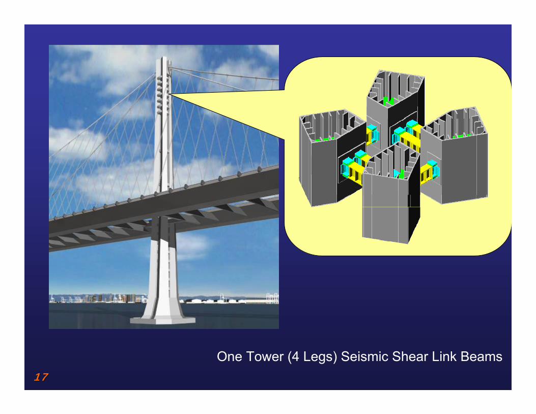
1717One Tower (4 Legs) Seismic Shear Link Beams
1818
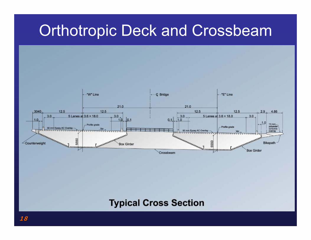
Orthotropic Deck and Crossbeam
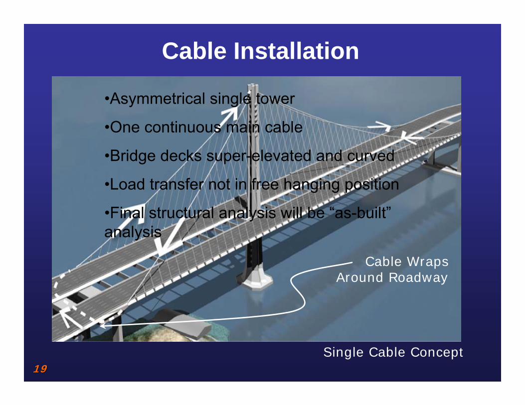
1919Single Cable Concept
Cable Wraps Around Roadway
Cable Installation
•Asymmetrical single tower
•One continuous main cable
•Bridge decks super-elevated and curved
•Load transfer not in free hanging position
•Final structural analysis will be “as-built”analysis
2020
5.4mm Zinc Galvanized Wire
5.4mm Zinc Galvanized Wire
127 Wire PWS Strand with Grease Application of Individual Wire
127 Wire PWS Strand with Grease Application of Individual Wire
17,400 Wire Main Suspension Cable17,400 Wire Main Suspension Cable
Elastic Noxide Primer and PaintElastic Noxide Primer and Paint
S-Wire WrappingS-Wire Wrapping
Zinc Oxide / Zinc Dust PasteZinc Oxide / Zinc Dust Paste
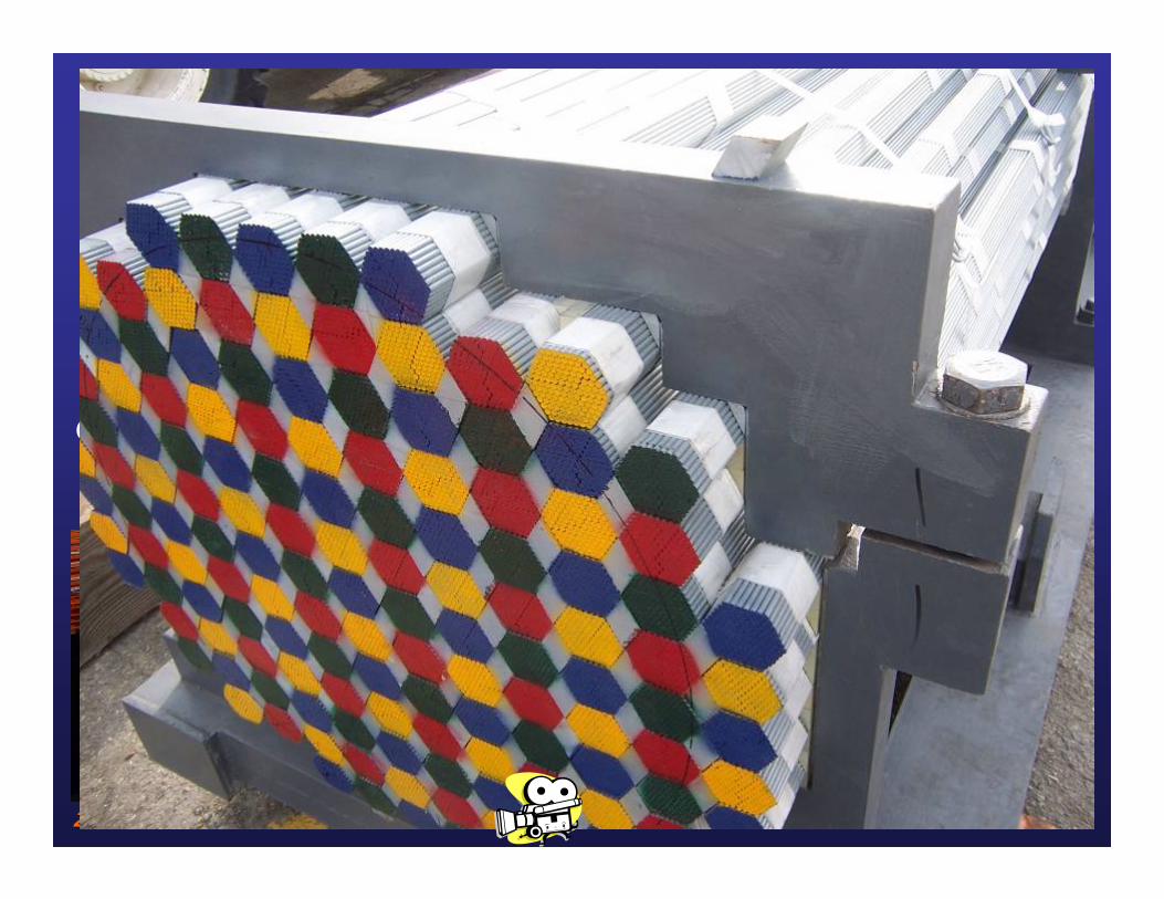
Cable is made up of 137 PPWS
Composition of SAS Cable

2121
SAS Saddle Location (Total 6)SAS Saddle Location (Total 6)(1) Tower Saddle
(2) Splay Saddles
(2) Deviation Saddles
(1) Jacking Saddle
2121

2222
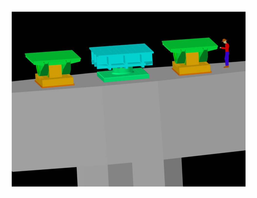
West Deviation and Jacking Saddles at W2
West Deviation and Jacking Saddles at W2
StatusDeveloping pattern for “E” line segment 2 Molding saddle for “E” line segment 1
Hinge K
Deviation SaddleJacking Saddle

2323
Hinge KHinge K
2424
E2 Bearing and Shear Key

2525
Tower Bolted Splice Details

2626
Bolting
• ASTM A490M bolts with Dacromet coating– A490 bolts rarely used on bridges– Coatings not allowed by current standard– No rotational capacity criteria for metric
• Bolting in confined space

2727
International Fabrication

2828
Fabrication Process
Japan
Saddles-Japan Steel WorksKorea
Suspender Cables-Kiswire
Bearings- Hochang Machinery Industries
Shear Key- Hochang Machinery Industries
PWS Cables-Shanghai Pujiang Cable Co
Tower Fabrication - ZPMC
Orthotropic Box Girder Sections - ZPMC
Bikepath - ZPMC
Shanghai
Pipe Beams-Oregon Iron Works
Washington
Misc Steel-D.S Brown & Westmont Industries
Minnesota
So. Calif
SAS SAS -- International Fabrication EffortInternational Fabrication Effort
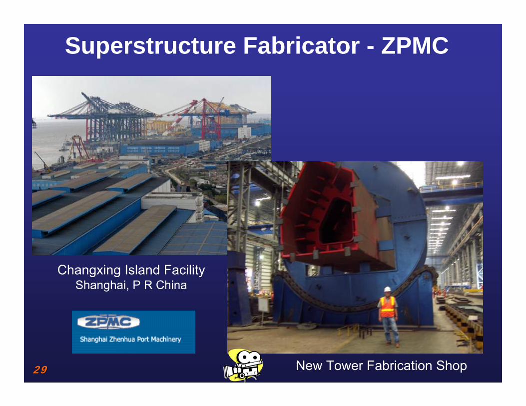
2929 New Tower Fabrication Shop
Superstructure Fabricator - ZPMC
Changxing Island FacilityShanghai, P R China

3030
Tower

3131
Orthotropic Box Girder
U-Rib Bending Machine
Submerged Arc Welding Gantry

3232
Orthotropic Box Girder
OBG Lifts Lined Up
OBG Lift Assembly

3333
Delivery of OBG and Tower Lifts

3434
Saddle FabricationSaddle FabricationJAPAN STEEL WORKS
Casting West Deviation Saddle

3535
Saddle Fabrication Types:Saddle Fabrication Types:
Machining West Deviation Saddle

3636
Shanghai Pujiang Cable Co., Ltd.
PWS Cable Taping
PWS Cable Assembly

3737
Goodwin Steel Castings
Mock-up Casting
Pattern Shop

3838
Xitang, PRC
PWS Cable
Stoke-on-Trent, UK
Cable Bands

3939
Temporary Bridge

4040
Temporary Works
W2E2
CA B D F G
1 2 3 4 5 6 87 109 1211 13 14
H
T1
Facts• 6,500 Mtons of Piling consisting of 48” x 1-1/4 and 42” x 1-1/2”• 4,300 Mtons for Towers• 5,500 Mtons Truss Material• 2,124 Mtons of Driving Frames

4141
Temporary Tower Foundations

4242
Temporary Bridge
4343
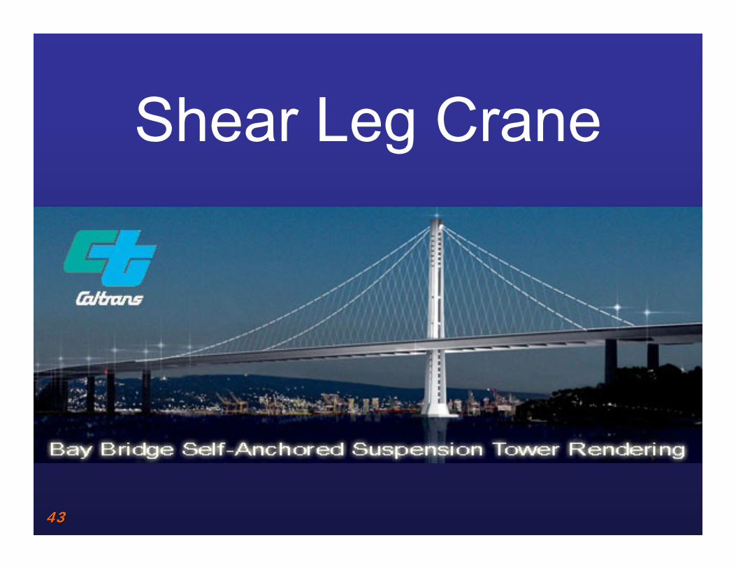
Shear Leg Crane

4444
Shear Leg Crane and Barge
Lifting Capacity: 1700 MtonsBoom Length: 100 MetersSelf Erecting Boom

4545
Shear Leg Crane

4646
Concrete Works

E2 Crossbeam
W2 Cap Beam

4848
W2 Cap Beam Details Elevation

4949
Cable Tie-down Details
5050
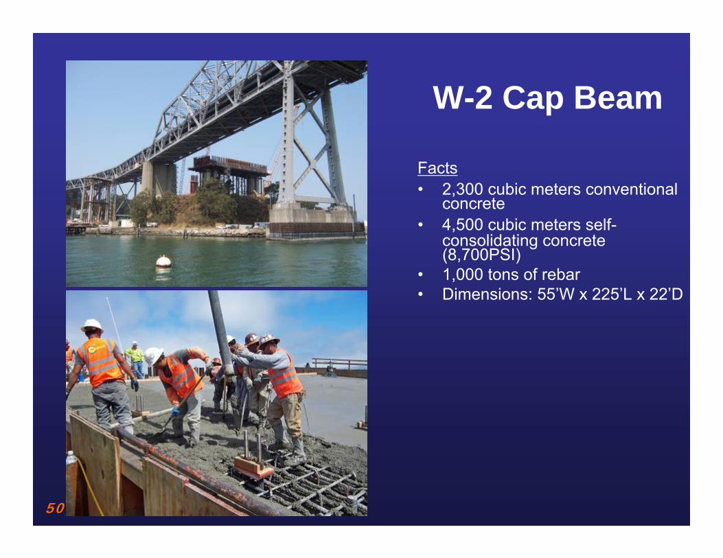
W-2 Cap Beam
Facts• 2,300 cubic meters conventional
concrete• 4,500 cubic meters self-
consolidating concrete (8,700PSI)
• 1,000 tons of rebar• Dimensions: 55’W x 225’L x 22’D

5151
Pier E2 Details
5252
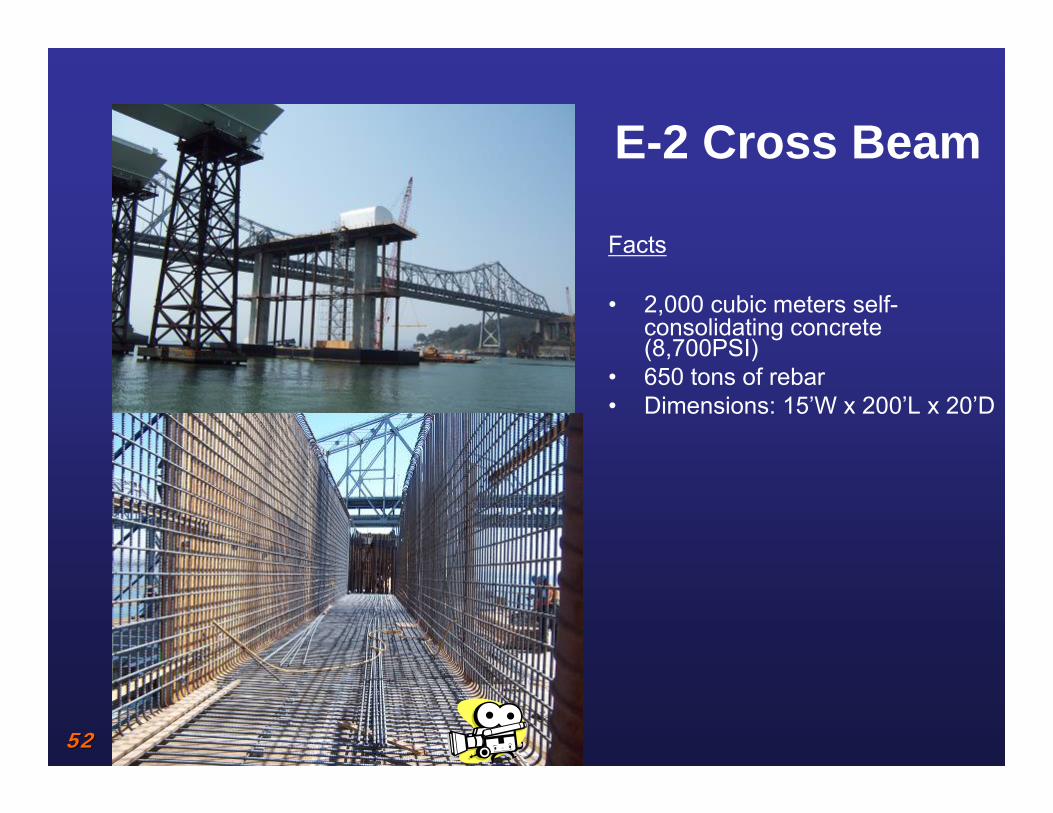
E-2 Cross Beam
Facts
• 2,000 cubic meters self-consolidating concrete (8,700PSI)
• 650 tons of rebar• Dimensions: 15’W x 200’L x 20’D

5353
Quality Program

5454
Facility Audits
5555
Audits (40 performed to-date)• Extensive in-depth facility audits
– Audit checklist from lessons learned– Paperwork approval (English only) before audit– Facility audit
• American standards• Verify capability and control/traceability though out the
process• Extensive international travel• Some doing work for Caltrans on other projects do not
receive a pass for the SAS• Extends to lower tier subcontractors
– Cannot start ANY work until passing an audit– Financial penalties for failing an audit
5656
Quality Programs

5757
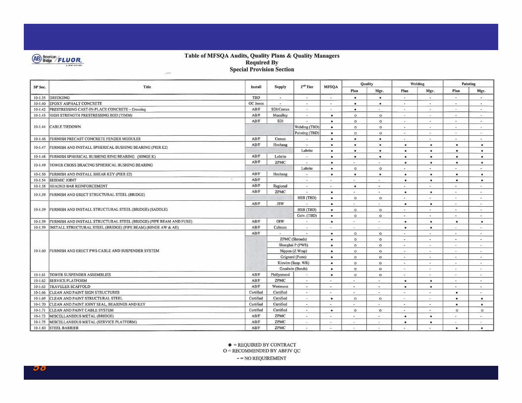
QUALITY PLANS(14 approved to-date)
• CONTRACT DOES NOT REQUIRE ONE COMPREHENSIVE ABFJV QC PROGRAM/MANUAL
• SPECIFIC CONTRACT QUALITY PROGRAM REQUIREMENTS– SEVERAL QC MANAGERS– SEVERAL QC PLANS– OTHER FABRICATION SPECIFIC PLANS (i.e., THERMAL
CONTROL PLAN, PRECAST FENDERS, BEARING LUBRICANT, CABLE BAND SLIP, etc.)
5858

5959
Mock-Upsand
Prequalification
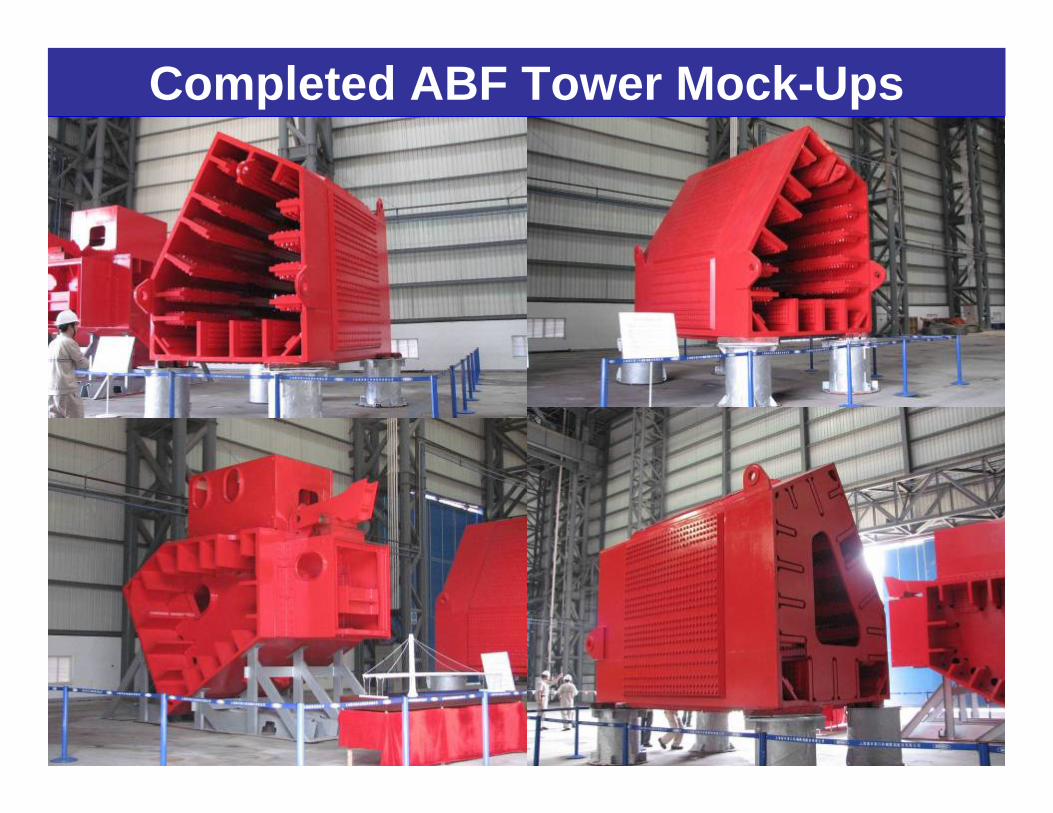
Completed ABF Tower Mock-Ups

6161
Electroslag Weld trials
6262
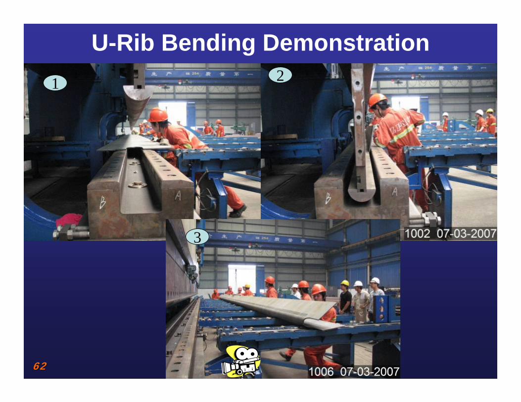
U-Rib Bending Demonstration1 2
3

6363
Cable CompactionCable Band Slip Test
6464
W-2 Cap BeamIntegrated Shop Drawings
1. Prepared Using “Navisworks” Program by ABFJV Personnel (Michael Lewis)
2. Modeling of Approximately 30,000 Elements which includes:a. Reinforcing Steelb. Post Tensioning Ductsc. Embedsd. High Strength Rods for Main Hinge & Deviation Saddles
3. Resolved 30,000 conflicts which was almost one conflict per every element modeled

6565
W-2 Cap BeamIntegrated Shop Drawings

6666
Reinforcing Mechanical Coupler Pre-qualifications

6767
W-2 Cap Beam
Formwork for Mass Concrete Demonstration Pour
SCC Pour Mock-up
Spread Test Performed During Self Consolidating Concrete Pour Mock-up

6868
NCR Processing

6969
NCR Processing
• Transition from serial letters with attachments to on-line document control process
• Lesson Learned – Technology is not the process. There need to be buy-in and commitments from all parties to make the system work
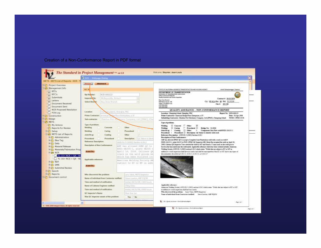
Creation of a Non-Conformance Report in PDF format

The NCR is transmitted to the Contractor

Quick search and status of all the Non-Conformance Reports and Non-Conformance Proposed Resolution reports

7373

7474
In-Process Tests and Inspections

7575
In-Process Tests and Inspections
• Coordination of inspection and testing activities– Numerous sub-consultant contracts– Domestic and international– Coordination with Caltrans

7676
In-Process Tests and Inspections
• Welding Quality Control– Procedure Qualifications– Welding Quality Control Plan
• Only AISC Category 3 facilities can self-perform welding NDT & inspection
– Daily Reports

7777
Welding QC Plan

7878

AMERICAN BRIDGE/FLUOR SFOBB BRIDGE PROJECT
QUALITY ASSURANCE SOFTWAREWELDLINKPRO©

8080

Designed by
Built by

8282
Introduction
• Web based Quality tool developed using Microsoft’s ASP.NET and C# programming language. Designed to be utilized by Fabricator, Contractor and Owner specifically to document the fabrication of the San Francisco Bay Bridge Project.
• Real time reporting of inspections and repairs before, during and after welding by use of hand held devices and wireless network.
• Material traceability through the use of bar code technology and Material Data Log.

8383
Introduction(continued)
• Accountability of welders through tracking repair rates by welder, process, position, joint configuration and cause.
• Insures all required inspections and repairs have been completed in advance of shipment.
• Provides access via the world wide web to unlimited personnel to view the real time inspection and repair status.

8484
Industries
• Bridge• Aerospace • Nuclear • Hydroelectric • Marine• Military • Construction

8585
Highlights
– Material traceability– Weld joint tracking – Welder performance tracking – Weekly Welding Report – Documentation – Benefits – Contact information

8686
Material traceability• Material traceability is accomplished by use
of bar code technology and/or traditional means of tracking items such as heat number and grade.
• Material information is compiled and stored on the Material Data Log as well as the Weld Data Log.
• Filtering allows the user to search by any desired combination of fields.
8787
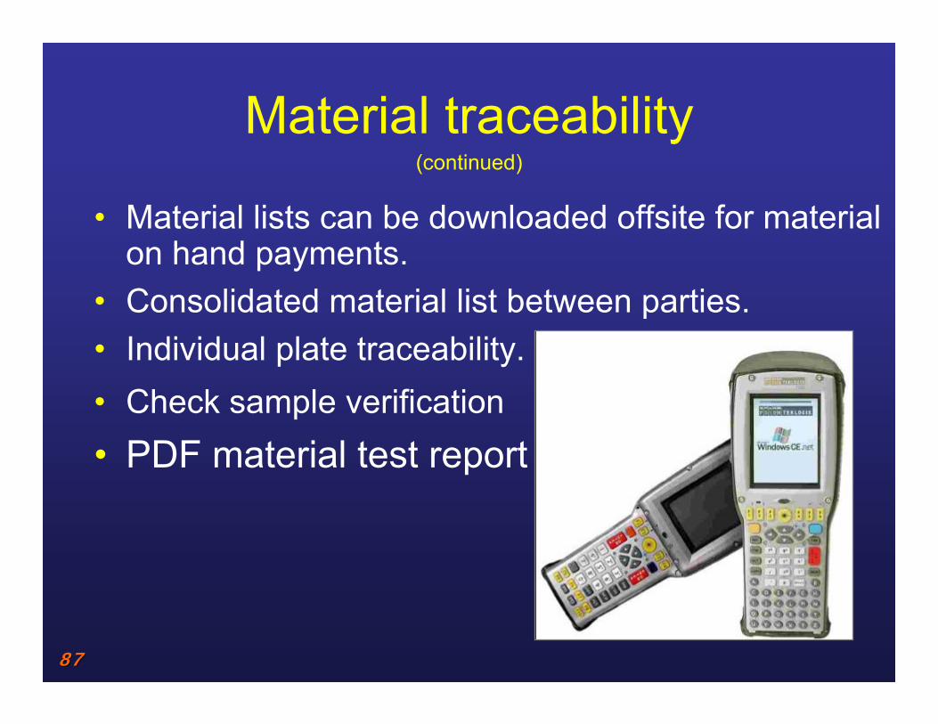
Material traceability (continued)
• Material lists can be downloaded offsite for material on hand payments.
• Consolidated material list between parties.• Individual plate traceability.• Check sample verification• PDF material test report

8888

8989

9090
Highlights
– Material traceability – Weld joint tracking – Welder performance tracking – Weekly Welding Report – Documentation– Benefits – Contact information

9191
Weld Data Log
• A centralized location for each weld joint on the project.
• Created prior to weld joint fit up.• Outlines the required nondestructive testing.• Outlines the required in process inspections
per the contract requirements. • Provides material traceability used to
construct the weld.• Works in conjunction with weld maps.
9292
Weld Data Log(continued)
• Insures proper acceptance criteria is applied.
• Eliminates costly re inspections

9393

9494
Weld Data Log(continued)
• All inspection and repair reports are created via links from this central location.
• Captured data populates the weld reject log and daily production.
• Insures the correct acceptance criteria is applied during inspections.
• Eliminates the need for manual creation of reports reducing reporting errors.

9595
9696
Weld Data Log(continued)
• History of all repairs associated to the weld• Provides the positive proof all required
inspections and repairs have been completed.
• Supports the creation of the weekly welding report.
• Supports and captures revisions to repair reports such as critical weld repairs.
• May be utilized during the review of the weekly welding report

9797

9898
Highlights
– Material traceability – Weld joint tracking– Welder performance – Weekly Welding Report– Documentation– Benefits – Contact information
9999
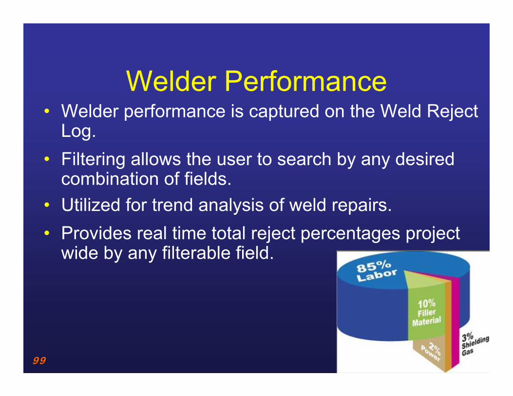
Welder Performance • Welder performance is captured on the Weld Reject
Log.• Filtering allows the user to search by any desired
combination of fields.• Utilized for trend analysis of weld repairs. • Provides real time total reject percentages project
wide by any filterable field.

100100
Welder Performance(continued)
– Inspector– Welder– Repair type – Weld identification – Location in the structure – Position – Process
– Joint type– Repair length– Repair depth– Repair width– Repair percent – Cause

101101
102102
Highlights
– Material traceability – Weld joint tracking– Welder performance tracking – Weekly Welding Report– Documentation– Benefits – Contact information
103103
Weekly Welding Report• Weekly Welding Report is Compiled electronically
following completion of tasks outlined on the Weld Data Log.
• Following review by the Quality Control Manager the Weekly Welding Report is submitted electronically to the Engineer for approval.
• During review by the Engineer the database may be available to verify current status of inspections and repairs.
104104
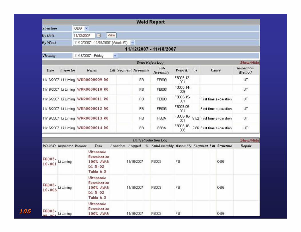
Weekly Welding Report (continued)
– Weekly Welding Report includes:• NDE reports• Critical Weld Repair Reports• Weld Repair Reports • Heat Straightening Reports• Nonconformance Reports• Weld Reject Log • Daily Production report
105105

106106
Highlights
– Material traceability – Weld joint tracking– Welder performance tracking – Weekly Welding Report – Documentation– Benefits– Contact information
107107
Documentation
• Records can be viewed electronically or printed.
• Final acceptance of components is obtained by producing a Data Acceptance Packet.
• Data Acceptance Packets are compiled after completing a query and are produced in PDF format.
108108
Documentation
• Data Acceptance Packet include the following– Nondestructive Testing Reports– Weld Repair Reports – Post Weld Repair NDE Reports– Weld Map– Weld Data Log – Material Test Report– In process inspections as required

109109
Highlights
– Material traceability – Weld joint tracking– Welder performance tracking – Weekly Welding Report – Documentation– Benefits – Contact information

110110
Benefits
• Real time wireless accurate and consistent reporting of inspection and repair results.
• Electronic submittal process reduces the approval time and personnel.
• Increased level of traceability of material, inspections and repairs result in decreased time and involvement by the customer before, during and after fabrication including shipment.
• Eliminates costly re-inspections of previously inspected and accepted welds and components.

111111
Benefits (continued)
• Shared information between all parties at all locations through the use of web based application.
• Onsite reporting increases floor coverage and decreases office time.
• Increased level of accountability of welders and inspectors.
• Localization (bilingual)
• Eliminate redundant tracking by multiple parties.
112112
Benefits (continued)
• Reduced exposure for omitted and duplicate reports.
• Customer satisfaction by providing access to the database during the review and approval of the Weekly Welding Report.
• Reduce costly repairs through trend analysis • May be implemented project wide• Paperless submittal process• Electronic report correlation and PDF printing

113113
Summary• Designed for the “Total Quality Management”
approach this unique tool will greatly enhance traditional Quality Control and Quality Assurance reporting and documentation.
• Web based application opens the door for cooperation between Fabricator, Contractor and Owner.
• Increases accountability for welders, inspectors and reviewers.
• Captures valuable data that can be utilized to establish controls to reduce or eliminate defects.
• Provides complete material traceability from beginning to end.
114114
Highlights
– Material traceability – Weld joint tracking– Welder performance tracking – Weekly Welding Report – Documentation– Benefits – Contact information

115115
Contact information
Inspectech Corporation
8550 W Charleston Blvd #102-148 ◦ Las Vegas, Nevada 89117 ◦ 503-550-9918
www.Inspectechconsulting.com
Further product information on WeldLinkPro can be found at the following website
www.WeldLinkPro.com
Copyright © 2006-2008 Inspectech Corporation All Rights Reserved.