sampling and plan - us environmental protection agency · sampling and analysis plan ... tclp...
TRANSCRIPT

LOWER DUWAMISH WATERWAY
SLIP 4 EARLY ACTION AREA
Sampling and Analysis Plan for Boundary Definition
Addendum Pre‐Design Investigation Sampling
Submitted to US Environmental Protection Agency Region 10 1200 Sixth Avenue Seattle WA 98101
Submitted by City of Seattle King County
Prepared by
7900 SE 28th Street Suite 300 Mercer Island WA 98040
June 8 2006
LOWER DUWAMISH WATERWAY
SLIP 4 EARLY ACTION AREA
Sampling and Analysis Plan for Boundary Definition
Addendum Pre‐Design Investigation Sampling
Submitted to US Environmental Protection Agency Region 10
1200 Sixth Avenue Seattle WA 98101
Submitted by City of Seattle King County
Prepared by
7900 SE 28th Street Suite 300 Mercer Island WA 98040
June 8 2006
Slip 4 Pre‐Design SAP Addendum June 8 2006
TABLE OF CONTENTS
LIST OF FIGUREShelliphelliphelliphelliphelliphelliphelliphelliphelliphelliphelliphelliphelliphelliphelliphelliphelliphelliphelliphelliphelliphelliphelliphelliphelliphelliphelliphelliphellipiv LIST OF TABLEShelliphelliphelliphelliphelliphelliphelliphelliphelliphelliphelliphelliphelliphelliphelliphelliphelliphelliphelliphelliphelliphelliphelliphelliphelliphelliphelliphelliphelliphellipiv ACRONYMS AND ABBREVIATIONShelliphelliphelliphelliphelliphelliphelliphelliphelliphelliphelliphelliphelliphelliphelliphelliphelliphelliphelliphellipv
1 INTRODUCTION 1‐1
2 PRE‐DESIGN DATA GAPS 2‐1 21 SELECTED ALTERNATIVE 2‐1 22 DATA GAPS FOR PRE‐DESIGN INVESTIGATION 2‐2
221 Field Conditions Documentation 2‐3 222 Additional Seep Characterization 2‐4 223 Additional Sediment and Soil Characterization 2‐5
23 SAMPLING DESIGN AND RATIONALE 2‐6 231 Field Conditions Survey 2‐6 232 Seep Water Sampling 2‐7 233 Surface Sediment Sampling 2‐8 234 Subsurface Sediment and Soil Sampling 2‐8
3 FIELD SAMPLING PLAN 3‐1 31 PROJECT ORGANIZATION 3‐1
311 Team Organization and Responsibilities 3‐1 312 Integral Personnel 3‐1
32 FIELD SAMPLING SCHEDULE 3‐2 33 FIELD SURVEY AND SAMPLING METHODS 3‐2
331 Field Conditions Documentation 3‐2 332 Seep Water Sampling 3‐3 333 Sediment and Soil Sampling 3‐4 334 Sample Handling and Transport 3‐7 335 Equipment Decontamination 3‐7 336 Investigation‐Derived Waste 3‐8
34 FIELD QUALITY CONTROL SAMPLES 3‐8 35 LABORATORY ANALYSES 3‐8
4 DATA MANAGEMENT AND REPORTING 4‐1 41 SAMPLE NUMBERING 4‐1 42 LABORATORY DATA 4‐2 43 DATA MANAGEMENT 4‐2 44 DATA REVIEW AND REPORTING SCHEDULE 4‐2
5 REFERENCES 5‐1
Integral Consulting Inc ii
Slip 4 Pre‐Design SAP Addendum June 8 2006
Appendix A Health and Safety Plan Appendix B Standard Operating Procedure Appendix C QAPP Addendum Appendix D Field Forms
Integral Consulting Inc iii
Slip 4 Pre‐Design SAP Addendum June 8 2006
LIST OF FIGURES
Figure 1‐1 Site Location Map Figure 2‐1 Site Features Figure 2‐2 Proposed Sampling Locations
LIST OF TABLES
Table 2‐1 Slip 4 Data Needs for Pre‐Design Investigation Table 2‐2 Slip 4 Proposed Sample Locations for Pre‐Design Investigation
Integral Consulting Inc iv
Slip 4 Pre‐Design SAP Addendum June 8 2006
ACRONYMS AND ABBREVIATIONS ASTM American Society for Testing and Materials bgs below ground surface bml below the mudline CC subsurface core sample DGPS Differential Global Positioning System DOC dissolved organic carbon EAA early action area Ecology Washington Department of Ecology EECA engineering evaluationcost analysis EOF emergency sewer overflow EPA US Environmental Protection Agency EQuIS Environmental Quality Information System FSP field sampling plan GIS geographic information system HSA hollow‐stem auger HSP health and safety plan LDW Lower Duwamish Waterway LDWG Lower Duwamish Waterway Group MLLW mean lower low water NTCRA non‐time‐critical removal action PCBs polychlorinated biphenyls PS pump station QAQC quality assurance and quality control QAPP quality assurance project plan RCRA Resource Conservation and Recovery Act SB subsurface bank soil composite sample SC subsurface core sample SD storm drain SG surface grab sample SOP standard operating procedure SP seep water sample SPT standard penetration test SVOCs semivolatile organic compounds TCLP Toxicity Characteristic Leaching Procedure TSCA Toxic Substances Control Act TOC total organic carbon TPH‐Dx extended diesel‐range total petroleum hydrocarbon TPH‐G gasoline‐range total petroleum hydrocarbon VOCs volatile organic compounds
Integral Consulting Inc v
Slip 4 Pre‐Design SAP Addendum June 8 2006
USCS Unified Soil Classification System UU unconsolidated undrained
Integral Consulting Inc vi
Slip 4 Pre‐Design SAP Addendum June 8 2006
This page intentionally left blank
Integral Consulting Inc vii
Slip 4 Pre‐Design SAP Addendum June 8 2006
1 INTRODUCTION
The City of Seattle and King County are planning a sediment removal action for cleanup of contaminated sediments in the Slip 4 Early Action Area (EAA) of the Lower Duwamish Waterway (LDW) Superfund Site in Seattle Washington (Figure 1‐1) The goal of the removal action is to significantly reduce the unacceptable risks to the aquatic environment that stem from potential exposure to contaminants in sediments in the slip (Integral 2006) Remediation of Slip 4 will also reduce potential human health risks associated with polychlorinated biphenyls (PCBs) in sediment within the LDW (Integral 2006)
An engineering evaluationcost analysis (EECA) for the Slip 4 removal action was submitted to the US Environmental Protection Agency (EPA) in February 2006 (Integral 2006) The EECA presents a proposed removal action boundary documents the development and evaluation of alternatives for conducting the non‐time‐critical removal action (NTCRA) and discusses the rationale for the recommended removal action Following public comment on the EECA EPA in consultation with the Washington Department of Ecology (Ecology) selected the removal alternative to be implemented by the City and King County (USEPA 2006)
This document is an addendum to the Lower Duwamish Waterway Slip 4 Early Action Area Sampling and Analysis Plan for Boundary Definition (Boundary Definition SAP) (Integral 2004b) This Pre‐Design SAP Addendum presents the sampling design and rationale for the collection of data needed to support the design of the removal action alternative (Alternative 2) selected by EPA Section 2 describes the recommended removal alternative identifies the pre‐design data gaps and describes the sampling design and rationale for the pre‐design field sampling plan (FSP) Section 3 contains the FSP which provides specific guidance for field procedures to be followed by Integral and its subcontractors during the field investigation Section 4 summarizes the data management procedures References cited in this report are listed in Section 5
The following documents are provided as appendices to this SAP
bull Health and Safety Plan (HSP) Addendum This document describes the requirements and procedures that will be implemented to ensure the safety of personnel that carry out the field investigation program (Appendix A) This addendum is provided as a supplement to the HSP presented by Integral (2004b)
bull Standard Operating Procedure (SOP) This SOP describes the procedures for using a hollow‐stem auger (HSA) to collect sediment samples with a split‐spoon sampler and a Shelby tube sampler (Appendix B)
Integral Consulting Inc 1‐1
Slip 4 Pre‐Design SAP Addendum June 8 2006
bull Quality Assurance Project Plan (QAPP) Addendum This document describes the organization functional activities and quality assurance and quality control (QAQC) protocols necessary to achieve the program‐specific data quality objectives for sample collection and analysis specified in this SAP (Appendix C) This addendum is provided as a supplement to the QAPP for the Boundary Definition SAP (Integral 2004b)
bull Field Forms These documents consist of boring logs sediment sampling forms and chain‐of‐custody forms (Appendix D)
This Pre‐Design SAP Addendum has been prepared according to USEPA (1988 1998 2002) and Ecology (2003) guidance and is consistent with work being performed for the LDW remedial investigation as described in the Boundary Definition SAP (Integral 2004b)
Integral Consulting Inc 1‐2
Slip 4 Pre‐Design SAP Addendum June 8 2006
2 PRE-DESIGN DATA GAPS
This section summarizes the recommended alternative the data gaps identified for the pre‐design investigation and the design and rationale for the pre‐design FSP
21 SELECTED ALTERNATIVE
Four removal alternatives were presented in the EECA (Integral 2006) Alternative 2 was recommended by the City and King County because it is considered to present the most practical and cost‐effective balance of contaminant removal and containment that ensures long‐term effectiveness provides the greatest habitat benefits and minimizes potential long‐term maintenance requirements (Integral 2006) EPA selected Alternative 2 in the Action Memorandum for a Non‐Time‐Critical Removal Action at the Slip 4 Early Action Area (USEPA 2006) Components of Alternative 2 include
bull Targeted removal by dredging of contaminated sediments at the head of the slip in order to remove near‐surface material with the highest concentrations of contaminants while minimizing changes to mudflat habitat at the head of the slip and accommodating outfall flows
bull Removal of piling and debris
bull Excavation of banks to ensure no net loss of aquatic habitat
bull Disposal of excavated and dredged material in a landfill that meets state and federal requirements for disposal of such material
bull Construction of engineered sediment caps over the entire Slip 4 removal area including engineered slope caps on the affected banks portions of the cap would be thickened and graded to expand and enhance shallow subtidal and intertidal habitat
bull Acquisition of the landownerrsquos permitted use of a berthing area (through purchase by the City of Seattle of property in the inner portion of the slip) because implementation of the removal will eliminate the berthing area
bull Implementation of institutional controls
bull Long‐term monitoring and reporting
bull Removal of sediment accumulations within the lowest segment of the Georgetown flume and potential outfall modifications
To accommodate these actions a portion of the existing Crowley pier may be removed from within the removal action area During project design the City of Seattle and King County will evaluate the most feasible approach to remediate the under‐pier area and to
Integral Consulting Inc 2‐1
Slip 4 Pre‐Design SAP Addendum June 8 2006
implement long‐term maintenance of that remedy The evaluation will include consideration of effectiveness implementability cost and habitat functions
22 DATA GAPS FOR PRE-DESIGN INVESTIGATION
Data needs to be filled in this pre‐design investigation include documentation of structures debris and outfall locations additional seep characterization and additional sediment and soil characterization for removal and cap placement
Additional data will be generated during the design but are outside the scope of this investigation These include
bull Sediment accumulations currently present within the lowest segment of the Georgetown flume (approximately 370 ft of the flume upgradient from the outfall itself) will be assessed Accumulated sediments that have the potential to recontaminate Slip 4 will be removed either as part of this removal action or as a separate action by the City of Seattle Modifications or upgrades to the Georgetown flume outfall structure may also be necessary as part of this removal action to ensure proper function of the outfall structure (ie free‐draining at a low tide) since it is currently at a lower elevation than the sediments immediately adjacent to the outfall Alternatives include designing the cap to accommodate the existing outfall structure raising the elevation of the outfall structure and abandoning the outfall structure Predesign investigations of the flume are being contracted and implemented separately by the City The results of these investigations will be presented in the Slip 4 EAA design documents or in a separate design package for the flume
bull Consistent with EPA and USACE guidance (USEPA 1998) caps constructed in Slip 4 will be engineered to withstand erosive forces (eg from outfall scour and propeller wash) Existing data such as outfall pipe construction details hydrographs vessel characteristics navigation areas etc will be assembled and analyzed during the design phase and no additional field data are required for this design component
bull During the design a structural survey of the Zone 4 bulkhead and Crowleyrsquos pier will be completed to document pre‐construction conditions of these structures If the decision is made to remove a portion of the Crowley pier the structural survey will generate the information required for the design of the pier removal
bull Finally existing bathymetrictopographic data for Slip 4 were collected in September 2004 and include high‐resolution survey data for all project areas including the under‐pier areas These data are sufficient for the design however minor shoaling or erosion may occur prior to construction The design may
Integral Consulting Inc 2‐2
Slip 4 Pre‐Design SAP Addendum June 8 2006
specify another pre‐construction survey to provide baseline bathymetry to be used for calculating payment volumes for the construction contractor
221 Field Conditions Documentation
2211 Structures and Debris
Structures in and adjacent to Slip 4 are illustrated in Figure 2‐1 The dominant structures in Slip 4 are the Crowley pier and berthing area along the western shoreline which are currently used for barge loading and unloading (Integral 2006) Portions of the east shoreline (First South Properties) and the bank at the head of the slip are lined with discontinuous segments of timber piles and wood‐lagging‐supported bulkheads and cinderblock bulkheads Parts of a derelict wooden loading structure remain on the western shoreline between the Crowley pier and the head of the slip (Integral 2006) There is a considerable amount of concrete debris and partially buried logs and piling near the toe of the banks around the head of the slip There is also a series of large timber skids at the head of the slip in the northwest corner The skids are mostly buried by sediment (Integral 2006) Documentation of current site conditions including a more thorough tally of site debris is needed for removal action planning
The information from this field documentation of visible debris will be used in the design to estimate the amounts and types of embedded debris that may be encountered during the dredgingexcavation The Design Analysis Report will evaluate how the debris should be handled and appropriate performance requirements This information (and all other relevant information from site investigations to date) will be provided to the construction contractor for its use in planning appropriate construction approaches to meet the performance requirements that will be specified in the design The specific construction approaches will be documented in the Remedial Action Work Plan subject to EPA approval
Geophysical features within the southern portion of the Zone 5 embankment on Boeing property will also be evaluated and documented This information will be used in developing design details for this transition area
In addition the presence or absence of fine‐grained deposits in the under‐pier riprap area will be assessed to provide information for the under‐pier cap design
2212 Emergency Overflow Outfall Location
Recent storm drain surveys have located numerous private storm drains and piped outfalls along the Slip 4 shoreline (SEA 2004) Five public outfalls are on record as discharging to Slip 4 at the head of the slip (Integral 2006)
Integral Consulting Inc 2‐3
Slip 4 Pre‐Design SAP Addendum June 8 2006
Former Outfall Name
Slip 4 SD (117)
Slip 4 EOFSD2
Current Outfall Name1
King County Airport SD 3PS44 EOF North Boeing Field SD
Outfall Diameter (inches)
60
24
I-5 SD I-5 SD 72
Georgetown flume
East Marginal Way EOF
Georgetown flume East Marginal Way PS EOF
60
36
Notes SD = storm drain EOF = emergency sewer overflow PS = pump station 1 Current outfall names were provided by Schmoyer (2006 pers comm) 2 Overflow from the Slip 4 EOFSD was rerouted to the Slip 4 SD (117) The current outfall names reflect this change
All of the public outfalls except for the East Marginal Way PS EOF have been located in the field The EOF will be located and photographed if possible
Private outfalls will also be located and photographed for design documentation
222 Additional Seep Characterization
Seeps occur in the lower intertidal areas of Slip 4 during low tides These seeps may include both groundwater discharge from nearby uplands as well as drainage of saturated nearshore fill material (Integral 2006) One of the seeps on the east side of Slip 4 (Seep 10 Figure 2‐2) was sampled during the Lower Duwamish Waterway Group (LDWG) survey in 2004 (Windward 2004b)1
The sample of seep discharge collected in 2004 was filtered in the laboratory using a 1‐μm filter and analyzed for mercury semivolatile organic compounds (SVOCs) PCBs (as Aroclors) and chlorinated pesticides The filter size was chosen to remove non‐colloidal particles greater than 1 μm that may have been introduced into the seep water by the sampling method Because the turbidity of the sample from Seep 10 was greater than 5 NTU only filtered samples were analyzed (except for the VOC sample) The sample for other inorganics was filtered through a 045‐μm filter to represent dissolved fraction The volatile organic compound (VOC) sample was not filtered
1 Sufficient water could not be collected at Seep 10 using the mini‐piezometer method As a result seep water was collected by placing a funnel with attached tubing into the flowing seep water channel and flow was directed into the sample container
Integral Consulting Inc 2‐4
Slip 4 Pre‐Design SAP Addendum June 8 2006
PCB concentrations were not detected above the 017‐μgL reporting limit (Windward 2004b) The concentration of one metal copper (at an estimated concentration of 869 J μgL) was greater than the acute and chronic marine water quality criteria (48 and 31 μgL respectively) However this result was qualified as an estimate because copper was detected in the rinsate blank2 In addition copper concentrations (including reporting limits for nondetects) exceeded the water quality criteria at all 18 seeps sampled in the LDW in this investigation (Integral 2006) All other chemicals in the sample from Seep 10 were undetected or less than water quality criteria (Integral 2006) The seep data support the conclusions of previous groundwater studies that although Seep 10 is an area of elevated sediment contaminant concentrations groundwater is not a significant contaminant source to Slip 4 sediments
Analytical data from other seeps in Slip 4 will be used to assess potential contaminant concentrations in these seeps these data may be used in cap design The additional seep samples will be analyzed for PCBs because they are the primary chemicals of concern in Slip 4 sediments
223 Additional Sediment and Soil Characterization
2231 Verification of Removal Boundary
The southwestern extent of the removal boundary in Shoreline Zone 5 is based on sample results collected north of the current removal boundary (Integral 2006) and the presence of engineered riprap south of the removal boundary As requested by EPA additional data characterizing the intertidal surface sediment on the riprap bank of the Boeing property immediately south of the removal boundary are needed to confirm the boundary location
2232 Removal Area Dredging Evaluation
The general physical characteristics of the sediment proposed for dredging need to be characterized which will help in assessing sediment behavior during dredging handling dewatering and disposal
2233 Removal Area Sediment and Bank Soil Characterization for Disposal
Planning for the disposal of material to be removed will require additional characterization of sediment and bank soil within the removal boundary Existing data indicate most or all of the excavated and dredged material will have total PCB concentrations less than 50 mgkg making it potentially suitable for placement in a
2 Sample concentrations between 5 and 10 times the rinsate blank concentration are qualified as estimates (Windward 2004b) The copper concentration at Seep 10 (869 J μgL) is 54 times the associated rinsate blank concentration (161 μgL) and so is qualified as an estimate (ldquoJrdquo)
Integral Consulting Inc 2‐5
Slip 4 Pre‐Design SAP Addendum June 8 2006
Resource Conservation and Recovery Act (RCRA) Subtitle D solid waste landfill (Integral 2006) However additional analyses are needed to determine whether the material will qualify as a Washington State‐regulated dangerous waste Testing to determine the materialrsquos dangerous waste status will require bulk analysis and potentially Toxicity Characteristic Leaching Procedure (TCLP) analyses
In addition federal regulations under the Toxic Substances Control Act (TSCA) regarding the disposal of remediation waste with PCB concentrations ge50 mgkg may apply to sediment in a limited area at the head of the slip in the vicinity of the historical sampling station SL4‐6A Total PCB concentrations of 150 mgkg were detected in the 0ndash60 cm sample interval at this location in 1990 (Landau 1990) Additional sediment samples are needed to determine if a definable area exists where PCB concentrations are greater than 50 mgkg If so the design will evaluate if it is practicable for the material excavated from this area to be segregated during construction (Integral 2006)
2234 Cap Geotechnical Characterization
Capping of in situ surface sediment is planned for the southern portion of the removal area (Integral 2006) Samples for geotechnical analysis will be collected to determine the load‐bearing and consolidation properties of the sediment (Table 2‐1) These data will provide strength and index properties of the underlying sediment and will be used in the design to define any limitations on cap placement rates or thicknesses support slope stability evaluations and predict the expected consolidation of the material beneath the cap
23 SAMPLING DESIGN AND RATIONALE
This section describes the sampling strategy developed to address the identified pre‐design data gaps Additional investigations are needed to characterize overall field conditions surface and subsurface sediment seep water and bank soil The types of samples required the rationale and analyses are listed in Table 2‐1 The proposed subsurface core and bank sample and surface grab sample location coordinates are listed in Table 2‐2
231 Field Conditions Survey
A survey of current field conditions at the slip will be conducted during a very low tide In particular the extent and types of debris visible in the slip will be noted private outfalls will be photographed and attempts will be made to locate the East Marginal Way PS EOF Additionally the locations of seeps observed during the field survey will be noted to identify the seeps to be sampled
Integral Consulting Inc 2‐6
Slip 4 Pre‐Design SAP Addendum June 8 2006
In the under‐pier riprap area the presence or absence of fine‐grained deposits will be assessed to provide information for the under‐pier cap design Three transverse sections from approximately 0 ft mean lower low water (MLLW) to +12 ft MLLW will be visually and photographically documented for presence of fine‐grained material in riprap interstices
Geophysical features within the southern portion of the Zone 5 embankment on Boeing property will be visually evaluate and documented
In addition a structural survey of the Zone 4 bulkhead and Crowleyrsquos pier will be completed to document pre‐construction conditions of these structures This survey will be accomplished at a later date during the design process If the decision is made to remove a portion of the Crowley pier the structural survey will generate the information required for the design
232 Seep Water Sampling
Intertidal seep samples are planned to further quantify any PCB concentrations that may be present in discharges of upland groundwater to the slip The sediment cap can be designed using existing data from the LDW seep survey and established procedures in EPAUSACE (USEPA 1998) guidance for evaluating contaminant transport Based on the results of the LDW seep survey and current knowledge of the surrounding upland areas EPA and Ecology did not believe that additional seep sampling was necessary for source control determinations related to Slip 4 sediments However during development of the EECA the community voiced concerns that additional seep data should be collected (DRCC 2006) Based on the community concern additional seep samples will be collected This information will provide additional data that may be used in the sediment cap design
Seep sampling will consist of the collection of water samples from four to six seeps the locations of which will be selected based on field observations (see Table 2‐1) Seep sampling will be conducted along Zone 2 through 5 (see Figure 2‐2) where seeps are identified The procedures to be used for seep sample collection will generally follow methods used for previous seep sampling (Windward 2004a) discussed in Section 332 below Seep samples will be collected at low tide and submitted for laboratory analysis of PCBs as Aroclors and dissolved organic carbon (DOC) Field water quality parameters (temperature conductivity turbidity dissolved oxygen pH salinity and oxidation‐reduction potential) will be collected from the seep prior to sampling Water quality parameters will also be collected in the adjacent surface water at the time of sampling each seep
Integral Consulting Inc 2‐7
Slip 4 Pre‐Design SAP Addendum June 8 2006
233 Surface Sediment Sampling
Surface sediment data are needed to assess intertidal sediment conditions on the riprap bank of the Boeing property and will be used to verify the location of the removal boundary in that area Four intertidal locations (SG30 31 32 and 33) south of the removal boundary in Shoreline Zone 5 at elevations above 0 ft MLLW will be sampled the approximate locations are illustrated in Figure 2‐2 Analytical parameters for these surface samples will include PCBs as Aroclors and total organic carbon (TOC) (see Table 2‐1)
234 Subsurface Sediment and Soil Sampling
Subsurface sediment and soil data are needed to
1 Characterize removal area sediment physical properties for dredging evaluation
2 Characterize removal area sediment and soil for potential disposal under Washington State Dangerous Waste regulations
3 Characterize removal area sediment near the head of the slip that may require potential disposal under TSCA
4 Evaluate sediment‐bearing capacity and consolidation properties for the cap design
5 Provide data for slope stability (static and seismic) analyses in design
The samples that will address these needs are discussed in this section and presented in Table 2‐1
All subsurface soil samples will be characterized according to the Unified Soil Classification System (USCS) as per current annual American Society for Testing and Materials (ASTM) Methods (ASTM 2003) This visualmanual classification will occur in the field per ASTM D2488 and will be recorded on boring logs except where undisturbed samples for geotechnical characterization are submitted to the laboratory For those samples the laboratory will perform the USCS classification following ASTM D2487
2341 Removal Area Characterization
Shelby tube samples will be collected from HSA borings at three locations in the area to be dredged (Stations SC12 SC13 and SC16 see Figure 2‐2) which includes the historical sampling location SL4‐6A (SC16 Landau 1990) to evaluate sediment physical properties for remedial dredging evaluation and disposal requirements The cores will extend from the surface to 5 ft below the mudline (bml) Samples from three discrete intervals will be collected from each core using a Shelby tube sampler advanced with a barge‐mounted
Integral Consulting Inc 2‐8
Slip 4 Pre‐Design SAP Addendum June 8 2006
HSA drilling rig The samples will be extruded and classified according to the USCS in the field Samples from each interval will be submitted for analysis of geotechnical parameters including water content specific gravity grain‐size distribution Atterberg limits and TOC The target sample intervals are 0ndash2 ft 2ndash4 ft and 4ndash5 ft bml however the actual intervals will be selected in the field so that each sample represents only one type of sediment If the sediment is uniform the target intervals will be used If there is a change in sediment type (ie from plastic silt to sand) the sample intervals will be adjusted
To determine the disposal requirements for the sediment to be dredged one composite sample representing the total lengths of the three cores (SC12 SC13 and SC16 combined) will be collected This sample will be submitted for the following chemical analyses for disposal characterization PCBs SVOCs metals chlorinated pesticides extended diesel‐range total petroleum hydrocarbons (TPH‐Dx) gasoline‐range TPH (TPH‐G) and TOC A sample aliquot will be collected for TCLP analysis of SVOCs metals and chlorinated pesticides and will be archived at the laboratory TCLP analysis will be contingent on the results of dry‐weight analysis TCLP analysis will only need to be performed if the TCLP contaminants in the results from the total analysis are greater than or equal to 20 times the maximum concentration for toxicity characteristic regulatory levels (set forth in Table 1 of 40 CFR 26124) The ldquo20 times rulerdquo is allowable because of the sample dilution that is a component of the TCLP Method 1311 (Section 12 of this method) as is clarified in EPA 540‐R‐94‐005a
To determine the disposal requirements for the bank sediment to be removed one composite sample of soil from the surface to a depth of approximately 3ndash4 ft bgs will be collected from SB21 and one composite sample of soil from similar depths will be collected from SB22 and SB23 The bank borings or test pits will be logged and soils will be classified by the USCS in the field The two composite samples will be submitted for SVOCs metals chlorinated pesticides TPH‐Dx TPH‐G TOC and geotechnical analyses including water content specific gravity grain‐size distribution and Atterberg limits Sample aliquots collected for TCLP analysis of SVOCs metals and chlorinated pesticides will be archived at the laboratory and analysis will be contingent on the results of dry‐weight analysis
Subsurface sediment cores will be collected to determine if there is a definable and separately manageable area with PCB concentrations requiring TSCA disposal near the historical SL4‐6A location Five HSA cores extending from the surface to 5 ft bml will be collected at the historical location SL4‐6A (SC16) and surrounding locations (SC14 SC15 SC17 SC18 see Figure 2‐2) The samples will be collected in Shelby tubes extruded in the field and classified by USCS Composite samples representing the full core length will be collected from each core (ie five samples) and submitted for PCB analysis
Integral Consulting Inc 2‐9
Slip 4 Pre‐Design SAP Addendum June 8 2006
Archived sediment samples from vibracore SC01 collected in April 2004 will be submitted for analysis of the following geotechnical parameters to determine the dredgeability and handling characteristics of the sediment USCS classification water content TOC specific gravity grain‐size distribution and Atterberg limits A total of three archived samples from this core have been selected consisting of the 0ndash2 2ndash4 and 4ndash6 ft sample intervals
2342 Cap Geotechnical Characterization
Samples will be collected to evaluate consolidation of sediments underlying the cap as well as the bearing capacity and slope stability of the underlying sediments These data will be used in cap design An HSA equipped with both a Shelby tube sampler and a split‐spoon sampler will be advanced to 20 ft bml (sampling method to be determined based on observed soil conditions) Samples for geotechnical analysis will be collected in Shelby tubes at Stations SC19 SC20 SC21 and SC22 from 0 to 25 ft 25 to 50 ft and 50 to 75 ft bml The Shelby tubes will be capped in the field and submitted to the lab Split‐spoon samples will be taken from depths of 75 ft to the bottom of the boring at intervals of 25 ft logged in the field per USCS (ASTM D2488) and standard penetration test (SPT) blowcounts will be recorded No chemical or geotechnical analyses of these deeper sample intervals are planned but deeper samples will be archived for potential additional index testing Samples will be handled and shipped as described in Section 334
From each boring location one or two representative subsamples of fine‐grained sediment from the Shelby tubes will be analyzed by consolidation testing and unconsolidated undrained (UU) triaxial shear testing The actual sample intervals for consolidationstrength testing will be selected by the field coordinator when the samples are extruded at the lab and will be based on material characteristics These analyses will be run on an approximate 6‐in interval of sediments
In addition from each boring location one or two representative subsamples from the Shelby tubes will be analyzed for grain‐size distribution USCS classification in the laboratory (ASTM D2487) water content bulk density specific gravity Atterberg limits and TOC The above parameters will be analyzed on 1 or 2 samples per boring location even if it is determined that the sediments are not fine‐grained Additionally if noncohesive sand layers are encountered direct shear testing of those layers may be conducted
Integral Consulting Inc 2‐10
Slip 4 Pre‐Design SAP Addendum June 8 2006
3 FIELD SAMPLING PLAN
The following sections describe the project organization anticipated field event schedule field survey and sampling methods (and other procedures that will be followed during field operations) and the laboratory analyses to be conducted This information augments the field sampling plan provided in the Boundary Definition SAP (Integral 2004b)
31 PROJECT ORGANIZATION
This section presents the organizational structure for sampling and analysis activities associated with the Slip 4 pre‐design investigation including team organization and responsibilities fieldwork data management and laboratory analyses
311 Team Organization and Responsibilities
The organization and responsibilities of the investigation team remain as presented in the Boundary Definition SAP (Integral 2004b)
Ms Karen Keeley US EPA Region 10 is EPArsquos Remedial Project Manager for Slip 4 Ms Keeley is responsible for approving this SAP and any subsequent modifications
Ms Ginna Grepo‐Grove US EPA Region 10 is EPArsquos Quality Assurance Manager for this project Ms Grepo‐Grove will review and provide final approval of the QAPP Addendum and data quality report
Ms Jennie Goldberg is the Project Coordinator and the City of Seattlersquos Project Manager responsible for providing contract direction to Integral
Integral is responsible for implementing the sampling program and preparing the associated reports for US EPA Region 10 on behalf of the City of Seattle and King County
312 Integral Personnel
Integral project personnel for the Pre‐Design SAP Addendum are identified below
Integral Consulting Inc 3‐1
Slip 4 Pre‐Design SAP Addendum June 8 2006
Position Personnel Integral Principal in Charge Project Manager Field CoordinatorSafety Officer Project QA Coordinator Laboratory Coordinator and QA Manager Data Manager
Betsy Day David Schuchardt Jane Sund or Susan FitzGerald Reid Carscadden Maja Tritt Tom Schulz
The organizational structure of the lead sampling and analysis personnel and analytical laboratory is shown in Figure 1 of the QAPP Addendum (Appendix C) Project roles remain as outlined in the Boundary Definition SAP (Integral 2004b) with modifications reflected in Figure 1 of Appendix C
32 FIELD SAMPLING SCHEDULE
Field work for the pre‐design investigations is tentatively scheduled to begin in June 2006 and estimated to be completed in 5 days Many of the field tasks depend on tide levels and will be scheduled accordingly
33 FIELD SURVEY AND SAMPLING METHODS
The Slip 4 pre‐design elements include a field conditions survey seep water sampling intertidal surface sediment sampling subsurface bank soil sampling and subsurface sediment coring The methods to be used for the collection of these field data are described in this section All field documentation station positioning sample handling equipment decontamination waste disposal chain‐of‐custody and QC procedures will follow those described in the Boundary Definition SAP except where noted below (Integral 2004b) All field documentation will be recorded on either boring logs or sample collection forms (Appendix D) All sample locations will be located using a Differential Global Positioning System (DGPS) as described in the Boundary Definition SAP (Integral 2004b)
All field activities will be conducted in accordance with the site‐specific HSP that is provided in Appendix A
331 Field Conditions Documentation
The objectives of the field conditions documentation are to
bull Record visible shoreline and intertidal debris near and at the head of the slip
Integral Consulting Inc 3‐2
Slip 4 Pre‐Design SAP Addendum June 8 2006
bull Attempt to locate the East Marginal Way PS EOF
bull Photograph and document conditions of all public and private outfalls
bull Note locations of intertidal seeps
bull Visually evaluate and document geophysical features within the southern portion of the Zone 5 embankment on Boeing property
bull Document the presenceabsence of fine‐grained deposits within the riprap in the under‐pier area
The site survey will consist of notes regarding the types locations and approximate quantities or areas of intertidal debris the anticipated location of the East Marginal Way PS EOF the locations of intertidal seeps and site photographs Site photos will include overviews and close‐up views of the site conditions noted as appropriate The coordinates of the EOF outfall will be recorded In the under‐pier area three transverse sections from approximately 0 ft MLLW to +12 ft MLLW will be visually and photographically documented for presence of fine‐grained material in riprap interstices
A structural survey of the pier and Zone 4 bulkhead will be completed at a later date
332 Seep Water Sampling
Four to six seep samples will be collected at locations identified in the field conditions survey Seeps with the highest visually apparent flow rates will be targeted for sampling Insufficient flow from some seeps may limit the total number of seep samples that can be collected
Seep water sampling will be conducted generally following the methods of Windward (2004a) Windwardrsquos QAPP identified stainless‐steel PushPoint mini‐piezometers developed and sold by MHE Products as the preferred sampling method and also identified three alternative sampling methods if the piezometers yielded high turbidity or insufficient flow
1 Placement of an appropriate sampling container directly under an actively flowing seep from a moderate‐ to steep‐sloping embankment
2 Placement of a glass funnel Teflonreg sheeting andor Teflonreg tubing as appropriate below seeps where water cannot be collected directly under the flow Pre‐assigned pre‐cleaned funnels sheeting and tubing will be used at each sampling location to avoid contamination from other locations Sampling equipment will be pre‐cleaned by Frontier as described in EPA Method 1669 (USEPA 1996)
Integral Consulting Inc 3‐3
Slip 4 Pre‐Design SAP Addendum June 8 2006
3 Excavating a pit in the sediment lining the pit with a stainless‐steel bowl allowing it to fill with seep water and dipping a pre‐cleaned glass beaker in the bowl to collect the seep water
The actual field sampling results from the Windward (2004a) sampling effort yielded insufficient flow at the seep location in Slip 4 (Seep 10) and the actual sampling method previously used in Slip 4 was the glass funneltubing alternative method described in the second bullet above
For this investigation the piezometer method is not proposed based on the previous experience in Slip 4 The preferred method for this investigation is the third alternative method described above This method is preferred over the funnel and tube method because it allows continuous readings of conventional water quality parameters prior to and during sampling provides a flow‐through cell for accurate measurement of conventional water quality parameters and minimizes sample disturbance such as changes in oxidation‐reduction potential
A small depression will be dug into the sediment immediately downgradient of the seep so that the seep flow will pool in the depression alternatively the flow may be directed into a decontaminated container inserted into the depression Measurements of water quality parameters (temperature conductivity turbidity dissolved oxygen pH salinity and oxidation‐reduction potential) will be collected from the pool of seep discharge the parameter readings will be allowed to equilibrate prior to recording Measurements will be recorded on the water sample collection form (Appendix D) The seep samples will be collected from the depression using a pre‐cleaned glass beaker or a peristaltic pump with attached dedicated disposable tubing Care will be taken to minimize the entrainment of sediment into the collected seep water Samples will be collected at low tide and at a period when minimum salinity is observed in the discharge to obtain a sample that is most representative of groundwater discharge Samples will be filtered in the field using a 1‐μm glass fiber filter Only filtered samples will be collected since any sediment entrained by the sampling method (even at low turbidity readings) could result in a high biased analytical result The filtered samples will be submitted for PCB and DOC analysis
Measurements of water quality parameters (temperature conductivity turbidity dissolved oxygen pH salinity and oxidation‐reduction potential) will also be collected from adjacent surface water at the time of sample collection at each seep
333 Sediment and Soil Sampling
The equipment and procedures that will be used to collect surface and subsurface sediment samples are discussed in the following sections Field documentation of sample collection will be recorded on either boring logs or sedimentsoil collection forms
Integral Consulting Inc 3‐4
Slip 4 Pre‐Design SAP Addendum June 8 2006
(Appendix D) Photographs will be taken of each sampling interval in the subsurface samples as well as from the individual sampling pits
3331 Surface Sediment Sampling
The surface sediment samples (0ndash10 cm) will be collected during low tide from intertidal Stations SG30 through SG33 using stainless‐steel bowls and spoons The surface sediment will be submitted for PCB and TOC analyses
3332 Subsurface Sediment and Soil Sampling
All subsurface soil samples will be characterized according to the USCS The Visual Manual Method (ASTM D2488) will be used in the field and will be recorded on boring logs except where undisturbed samples for geotechnical characterization are submitted to the laboratory For those samples the laboratory will perform the USCS classification following ASTM D2487 Samples will be handled and shipped as described in Section 334
Samples for Removal Area Characterization
Subsurface sediment cores for the dredge area characterization will be collected using Shelby tube samplers advanced through HSA borings from a barge‐mounted drill rig The proposed borehole locations are shown in Figure 2‐2 Samples will be collected from 0 to 5 ft bml at each location according to the SOP for HSAShelby tube sampling (SOP 6 Appendix B) The core intervals will be sampled discretely or composited per the requirements at each station The cores will be subsampled according to two to three different schemes as discussed below
Sediment cores from seven locations will be used to characterize sediment in the area to be dredged The cores will be subsampled into three sample intervals as described in Section 2 These discrete samples will be analyzed for geotechnical parameters as follows
bull Nine subsamples from SC12 SC13 and SC16 will be analyzed for grain‐size distribution water content specific gravity and Atterberg limits
Six samples will be submitted for chemical analysis to evaluate disposal requirements as follows
bull One composite sample representing the entire recovered lengths of cores from SC12 SC13 and SC16 will be submitted for chemical analysis to evaluate whether the material will require disposal as a Washington State Dangerous Waste Analysis of this sample will include PCBs chlorinated pesticides SVOCs metals
Integral Consulting Inc 3‐5
Slip 4 Pre‐Design SAP Addendum June 8 2006
TPH‐Dx TPH‐G TOC and TCLP analysis for SVOCs chlorinated pesticides and metals
bull Five samples each representing the entire recovered lengths of one of five discrete cores from Stations SC14 through SC18 near the head of the slip will be submitted for PCB analysis to determine if segregation of an area potentially requiring disposal under TSCA regulations is practicable
Bank material in the removal areas will be sampled and submitted for chemical analysis to evaluate whether the material will require disposal as a Washington State Dangerous Waste These bank samples will be collected from hand augers andor hand‐dug test pits advanced to approximately 3ndash4 ft bgs
bull One composite sample will be collected from SB21 representing the approximate 0ndash4 ft depth interval to be removed
bull One composite sample will be collected of material from SB22 and SB23 representing the approximate 0ndash4 ft depth interval to be removed
Chemical analysis of these bank samples will include PCBs chlorinated pesticides SVOCs metals TPH‐Dx TPH‐G TOC and TCLP analysis for SVOCs chlorinated pesticides and metals Geotechnical analyses for these samples will include grain‐size distribution water content Atterberg limits and TOC Due to the widespread occurrence of riprap andor buried debris it is anticipated that hand‐dug test pits (advanced using a shovel) will likely be necessary and locations may need to be adjusted in the field The cores or test pits will be logged and classified following ASTM D2488 The test pits will be logged from the excavated test pit sidewall
Cap Geotechnical Characterization
Subsurface sediment cores for capping geotechnical characterization will be collected using Shelby tubes and split‐spoon samplers advanced through HSAs following the SOP for Shelby Tube Sampling (SOP 6 Appendix B) The samples will consist of undisturbed Shelby tubes collected from the intervals described in Section 2 at Stations SC19 SC20 SC21 and SC22 The undisturbed Shelby tubes will be sealed and submitted to the analytical lab and up to two sample intervals from each boring will be analyzed for consolidation testing The sample intervals for lab testing will be determined by the Integral Field Coordinator at the lab Fine‐grained sediment subsamples will be analyzed by consolidation testing and UU triaxial shear grain‐size distribution water content bulk density specific gravity Atterberg limits and TOC The lab will also record the USCS classification of the undisturbed samples
Integral Consulting Inc 3‐6
Slip 4 Pre‐Design SAP Addendum June 8 2006
The deeper sample intervals from these borings (to 20 ft bml) will be continuously sampled using a split‐spoon sampler logged in the field per USCS and SPT blowcounts will be recorded
Archived Samples
Three archived samples from SC01 collected in 2004 will be analyzed for grain‐size distribution USCS classification water content and Atterberg limits
334 Sample Handling and Transport
Sample jars coolers and packaging material will be supplied by the analytical laboratory Details on the numbers and type of sample containers are provided in the QAPP Addendum (Appendix C) Seep water samples bank subsurface soil samples surface sediment samples and disturbed subsurface sediment samples will be handled and transported in accordance with the procedures in the Boundary Definition SAP (Integral 2004b)
Undisturbed Shelby tube samples will be handled following ASTM D3213 Standard Practice for Handling Storing and Preparing Soft Undisturbed Marine Soil This standard covers the methods for projectcruise reporting and handling transporting and storing soft cohesive undisturbed marine soil The tube ends of the undisturbed Shelby tube samples will be sealed in the field as per SOP 6 (see Appendix B) to prevent leakage of pore water The tubes will be maintained in a vertical orientation and transported to the laboratory with minimal disturbance
335 Equipment Decontamination
The handcores will be rinsed with site water and washed with Liqui‐noxTM detergent prior to use and between sampling stations Decontamination of stainless‐steel bowls and spoons will also be performed before using sampling equipment at each station using the following process
bull Rinse with site water bull Wash with Liqui‐noxTM bull Double rinse with distilled water bull Rinse with deionized water bull Rinse with methanol bull Final rinse with deionized water
If a residual petroleum sheen remains on the sampling equipment or is difficult to remove using the standard decontaminations procedures above a final hexane rinse may be added
Integral Consulting Inc 3‐7
Slip 4 Pre‐Design SAP Addendum June 8 2006
Sample equipment will be kept wrapped in aluminum foil until time for use To minimize sample cross‐contamination disposable gloves will be replaced between stations
336 Investigation-Derived Waste
Investigation‐derived waste will be managed as described in the Boundary Definition SAP (Integral 2004b)
34 FIELD QUALITY CONTROL SAMPLES
QC requirements will be instituted during field sampling laboratory analysis and data management to ensure that the data quality objectives from Integral (2004b) are met Detailed information on QAQC procedures limits and reporting are described in detail in the QAPP (Integral 2004b) and QAPP Addendum (Appendix C)
Field QC samples will be collected as specified in the Boundary Definition SAP (Integral 2004b) with the exception that field replicates will only be collected during seep sampling Field QC samples will include field split samples (for surface sediment sampling) and equipment rinsate blanks (for seep sampling and surface sediment sampling) The types and numbers of QC samples that will be collected are listed in Table 4 of the QAPP Addendum (Appendix C)
35 LABORATORY ANALYSES
Laboratory analyses will be performed according to the Boundary Definition QAPP (Integral 2004b) and the QAPP Addendum (Appendix C)
Integral Consulting Inc 3‐8
Slip 4 Pre‐Design SAP Addendum June 8 2006
4 DATA MANAGEMENT AND REPORTING
During field laboratory and data evaluation operations effective data management is the key to providing consistent accurate and defensible data and data products The management and reporting of field and laboratory data will generally follow the procedures outlined by Integral (2004b) Changes or additions to those procedures based on the specific requirements of this FSP are discussed in the following sections
41 SAMPLE NUMBERING
According to Integral (2004b) all samples will be assigned a unique identification code based on a sample designation scheme designed to suit the needs of the field personnel data management and data users Sample identifiers will consist of two components separated by dashes The first component is SL4 to identify the data as originating in Slip 4 The second part will contain the following abbreviations for the sample type followed by the sample number
SB = subsurface bank soil composite sample CC = subsurface sediment core composite sample SC = subsurface core sample SG = surface grab sample SP = seep water sample
All station IDs will be numbered sequentially Surface and subsurface stations will continue the numbering scheme begun during the 2004 sampling (Integral 2004a) Composite core samples and seep samples will each be numbered sequentially starting with 01
Subsurface core samples will also have a letter that is placed after the sample number to designate the sample horizon in the core ldquoArdquo will be used to indicate the top interval (ie 0‐ to 2‐ft horizon) All subsequent (deeper) sample intervals will be indicated in alphabetical order (ldquoBrdquo 2ndash4 ft ldquoCrdquo 4ndash5 ft) Core samples collected from the full length of the core will be indicated by ldquoXrdquo
Seep water samples and composite core samples will be numbered sequentially
Some examples of sample labels include
bull SL4‐SB02 Second composite subsurface bank soil sample the stations comprising this composite will be noted in the field log book
Integral Consulting Inc 4‐1
Slip 4 Pre‐Design SAP Addendum June 8 2006
bull SL4‐CC01 First composite sediment core sample the core stations comprising this composite will be noted in the field log book
bull SL4‐SC14C Core sample from the 4‐ to 5‐ft horizon at Station 14
bull SL4‐SC15X Sample representing the full length of the core collected at Station 15
bull SL4‐SG32 Surface grab sample from intertidal Station 32
bull SL4‐SP01 First seep water sample station
42 LABORATORY DATA
Laboratory data reporting procedures will follow those of the Boundary Definition SAP (Integral 2004b)
43 DATA MANAGEMENT
Data management procedures will follow those of the Boundary Definition SAP Integral will continue to use the Environmental Quality Information System (EQuIS) in conjunction with the ArcView 9 geographic information system (GIS) tools to manage summarize and report the generated data Pre‐design data will be submitted electronically to EPA in the SEDQUAL format
44 DATA REVIEW AND REPORTING SCHEDULE
Data validation procedures will follow those called for in the Boundary Definition SAP (Integral 2004b) The results of this pre‐design investigation sampling will be presented in a Pre‐Design Sampling Data Report that will be an appendix to the 60 Design Documents for the Slip 4 Early Action currently scheduled for fall 2006 Information to be included in the Data Report will include but is not limited to
bull Field methods and any deviations from the SAP bull Field change requests bull Actual sample locations bull Laboratory analysis results bull Data validation reports bull Core logs bull Sample description forms bull Photodocumentation bull Description of geophysical features on Zone 5 embankment bull Location of the East Marginal Way PS EOF outfall
Integral Consulting Inc 4‐2
Slip 4 Pre‐Design SAP Addendum June 8 2006
bull Summary of under‐pier sediment accumulations in riprap interstices bull Engineerrsquos estimate of debris types and quantities
Integral Consulting Inc 4‐3
Slip 4 Pre‐Design SAP Addendum June 8 2006
This page intentionally left blank
Integral Consulting Inc 4‐4
Slip 4 Pre‐Design SAP Addendum June 8 2006
5 REFERENCES
ASTM 2003 Annual Book of ASTM Standards Volume 0408 American Society for Testing and Materials Philadelphia PA
DRCC 2006 Comment Letter Re Draft Lower Duwamish Waterway Slip 4 Early Action Area EECA January 6 2006 Duwamish River Cleanup Coalition Seattle WA
Ecology 2003 Sediment Sampling and Analysis Appendix Guidance on Development of Sediment Sampling and Analysis Plans Meeting the Requirements of the Sediment Management Standards PTI Environmental Services Bellevue WA and Washington Department of Ecology Olympia WA
Ecology 2005 Memorandum Re Slip 4 Upland Soil and Sediment PCB Investigation August 22 2005 Prepared by Sunny Becker Washington Department of Ecology Olympia WA
Integral 2004a Lower Duwamish Waterway Slip 4 Early Action Area Cruise and Data Report Prepared for City of Seattle and King County WA Integral Consulting Inc Mercer Island WA
Integral 2004b Lower Duwamish Waterway Slip 4 Early Action Area Sampling and Analysis Plan for Boundary Definition Prepared for City of Seattle and King County WA Integral Consulting Inc Mercer Island WA
Integral 2006 Lower Duwamish Waterway Slip 4 Early Action Area Engineering EvaluationCost Analysis Prepared for City of Seattle and King County WA Integral Consulting Inc Mercer Island WA
Landau 1990 Environmental Site Assessment First Interstate Bank of Washington Property 7400 8th Ave S amp 7343 E Marginal Way S Prepared for The Boeing Company Seattle WA Landau Associates Inc Edmonds WA
Schmoyer B 2006 Personal Communication (email of January 23 2006 to V Fagerness Integral Consulting Inc Olympia WA regarding modifications to outfall names) Seattle Public Utilities Seattle WA
SEA 2004 Lower Duwamish Waterway Slip 4 Early Action Area Summary of Existing Information and Identification of Data Gaps Prepared for City of Seattle and King County WA Striplin Environmental Associates Olympia WA
Integral Consulting Inc 5‐1
Slip 4 Pre‐Design SAP Addendum June 8 2006
USEPA 1988 Guidance for Conducting Remedial Investigations and Feasibility Studies under CERCLA Interim Final OWSER Directive 93553‐01 EPA 540‐G‐89‐004 US Environmental Protection Agency Office of Emergency and Remedial Response Washington DC
USEPA 1998 Assessment and Remediation of Contaminated Sediments (ARCS) Program Guidance for In‐Situ Subaqueous Capping of Contaminated Sediments EPA 905‐B96‐004 Prepared by US Army Corps of Engineers (Michael Palermo Jan Miller) and Danny D Reible Louisiana State University Great Lakes National Program Office Chicago IL
USEPA 2002 Guidance on Quality Assurance Project Plans EPA QAG‐5 EPA240R‐02009 US Environmental Protection Agency Office of Environmental Information Washington DC
USEPA 2006 Action Memorandum for Non‐Time Critical Removal Action at the Slip 4 Early Action Area of the Lower Duwamish Waterway Superfund Site Seattle Washington dated May 3 2006 US Environmental Protection Agency Region 10 Seattle WA
Windward 2004a Quality Assurance Project Plan Survey and Sampling of Lower Duwamish Waterway Seeps Prepared for Lower Duwamish Waterway Group for submittal to US Environmental Protection Agency and Washington State Department of Ecology Windward Environmental LLC Seattle WA
Windward 2004b Data Report Survey and Sampling of Lower Duwamish Waterway Seeps Prepared for Lower Duwamish Waterway Group for submittal to US Environmental Protection Agency and Washington State Department of Ecology Windward Environmental LLC Seattle WA
Integral Consulting Inc 5‐2
FIGURES
4 5
Slip 4
ChannelSlip 4 Channel
East Marginal
MapD
ocum
ent(
OP
rojec
tsDu
wami
sh_O
LYP
rojec
tsSli
p4_E
ECAS
iteLo
catio
nMap
mxd
) 52
4200
6--1
0141
1AM
Seattle Elliott Bay
Spokane St Bridge
Duwamish Waterway
RM 1
1st Ave S Bridge
RM 3 Slip 4
16th Ave S Bridge
Burien
RM 5
Turning Basin No 3
E Marginal Way Bridge
Tukwila
Figure 1-1Site Location Map
Slip 4 Pre-design SAP Map Feature Sources King County GIS Seattle Public Utilities USACE Ecology and others
18
14
16
12
16
12
12
14
AV
S
8TH
AV
S
Duwamish Waterway
Slip 4
8
14
12
1 0
16
2 0 222 4 2 6
28
3 0
32
20
8
1 4
10
1 2
1 8
24
18
16
2 2
16
14
1 4
1 4
12
1 6
1 8
14
18
14
1 4
10
1 6
1 6
1 8
1 2
1 6
16
1 8
1 8
1 8
8 TH
S OTHELLO ST NP RR
E MARGINAL WY S
Map
Doc
umen
t (O
Pro
ject
sD
uwam
ish_
OLY
Pro
ject
sSl
ip4_
EEC
AFi
gure
_2-5
_Hab
itat_
size
-AP
mxd
)4
112
006
--4
193
8 P
M
0 50 100 150 200 Feet deg NAD83
Slip 4 area Habitat Typesbeach
vegetation
DataQueryArea
Paved edgeBuildings
Bulkhead
shallow subtidal
berths amp docks wriprap
Dredging Areas - Post-1990
riprapmudflat
Figure 2-1 Site Features
Slip 4 Pre-design SAP Map Feature Sources King County GIS Seattle Public Utilities USACE Ecology and others
TABLES
Slip 4 Pre‐Design SAP Addendum June 8 2006
Table 2-1 Slip 4 Data Needs for Pre-Design Investigations Chemical Analyses Geotechnical Analyses
Purpose Matrix Sample Type Sampling Frequency Stations Analytes Samples Laboratory Field4 Samples Notes
Field Conditions Documentation
-- -- -- -- -- -- -- -- -- Debris tally photodocument locate EOF assess under-pier sediment presence document Zone 5 characteristics Structural survey of pier and Zone 4 bulkhead (at later date)
Seep Water Sampling (Bank)
Water Intertidal seep grab1 Estimated 4ndash6 locations field-determined
SP01 through SP06 PCBs DOC 4-6 -- -- NA Filtered samples Collect at low tide per LDW procedures Field WQ parameters measured prior to sampling 1
Intertidal Surface Sediments Verify Intertidal Boundary at Boeing Riprap
Sediment Intertidal surface grab (0-10 cm from spoonbowl)
4 locations south of boundary above 0 ft MLLW
SG30 SG31 SG32 SG33
PCBs TOC 4 -- -- 0 Requested by EPA
Intertidal and Subtidal Subsurface Sediments Sediment Disposal Characterization - TSCA Remediation Waste
Sediment Intertidal HSAShelby tubes 5 ft deep
5 locations near SL4-6A one full-depth composite sample per core
Sediment Disposal Characterization -Washington State Dangeous Waste Dredgeability and Handling
Sediment Intertidal HSAShelby tubes 5 ft deep
3 locations in dredge area including one at SL4-6A Index properties on individual core segments Disposal characterization on one composited sample of all three 5-ft cores
Dredgeability and Handling Sediment Archived cores Archived sediment sample SC-01 0ndash2ft 2ndash4ft 4ndash6 ft
Cap Design - Geotechnical Characterization of Underlying Sediments
Sediment HSA to 20 ft bml 0-25 ft 25-5 ft 5-75 ft Shelby tubes Split spoons to 20 ft
4 locations in cap area From each location analyze one or two representative 6-in intervals of fine-grained material for consolidation and strength Analyze one or two additional intervals for index properties Sampling intervals to be determined in field based on stratigraphy of the sample
SC14 SC15 SC16 SC17 SC18
PCBs 5 -- USCS classification 03 To assess need for segregation of TSCA material gt50 mgkg PCB
SC12 SC13 SC16 On Composite SVOCs inorganics chlorinated pesticides PCBs TOC TPH-G TPH-Dx TCLP (SVOCs inorganics pesticides) 6
1 On individual sample intervals2 water content specific gravity grain size Atterberg limits TOC
USCS classification 9
SC01 (archived) -- -- USCS classification5
water content specific gravity grain size Atterberg limits TOC
-- 3
SC19 SC20 SC21 SC22
-- -- On Shelby tubes Consolidation and UU Triaxial Shear (only fine-grained materials will be analyzed for these parameters) For the following analyses representative subsamples will be analyzed regardless of material type USCS classification5 water content bulk density specific gravity grain size Atterberg limits TOC
On Split Spoons USCS classification
8 Borings to 20 ft bml with both SPT and Shelby sampling Engineer to direct SPTShelby sampling Submit capped Shelby tubes to lab for subsampling Archive representative split spoon samples Up to 2 consolidation and triaxial samples may be submitted per boring on silt or clay units
Integral Consulting Inc 1 of 2
Slip 4 Pre‐Design SAP Addendum June 8 2006
Table 2-1 Slip 4 Data Needs for Pre-Design Investigations Chemical Analyses Geotechnical Analyses
Purpose Matrix Sample Type Sampling Frequency Stations Analytes Samples Laboratory Field4 Samples Notes
Bank Subsurface Soils
Zone 2 Bank ExcavationDisposal Characterization
Bank soils Composite soil sample from hand auger boring or hand-dug test pit
One composite sample from a boring (to 3ndash4 bgs) in Zone 2
SB21 SVOCs inorganics chlorinated pesticides PCBs TOC TPH-G TPH-Dx TCLP (SVOCs inorganics pesticides) 6
1 Water content specific gravity grain size Atterberg limits
USCS classification 1
Zone 3 4 5 Bank Excavation Disposal Characterization
Bank soils Composite soil sample from hand auger borings or hand-dug test pits
One composite sample from borings (to 3ndash4 bgs) in Zone 3 4 and 5
SB22 SB23 SVOCs inorganics chlorinated pesticides PCBs TOC TPH-G TPH-Dx TCLP (SVOCs inorganics pesticides)6
1 Water content specific gravity grain size Atterberg limits
USCS classification 1
Notes surface 1 Field water quality parameters will be measured before sampling at each seep location and in adjacent surface water Parameters include temperature conductivity turbidity dissolved oxygen pH salinity and oxidation-reduction potential 2 Sample target intervals will be from 0ndash2 ft below mudline (bml) 2ndash4 ft bml and 4ndash5 ft bml 3 Geotechnical analyses on samples from SC16 are included under Sediment disposal characterization - Washington State Dangerous Waste 4 USCS classification will be conducted in the field following ASTM D2488 Visual Manual Procedure 5 USCS classification will be conducted by the laboratory following ASTM D2487 6 TCLP aliquots to be archived for potential future analysis -- - not applicable
Integral Consulting Inc 2 of 2
Slip 4 Pre‐Design SAP Addendum June 8 2006
Table 2-2 Slip 4 Proposed Sample Locations for Pre-Design Investigations
Station ID Northing Easting
SC12 1992785071 1273514482 SC13 1993604344 1273429089 SC14 1994268725 1273459595 SC15 1994252542 1273498824 SC16 1994490406 1273482094 SC17 1994657131 1273501524 SC18 199465893 1273468952 SC19 1988678836 1273370448 SC20 1990483314 1273510154 SC21 1992283014 127340771 SC22 1993978931 1273521878 SB21 1994112452 1273410305 SB22 1992791657 1273582561 SB23 1988407995 1273394217 SG30 1988051522 1273345121 SG31 198791841 1273358284 SG32 1987818575 1273352892 SG33 1987902563 1273335606
Notes Horizontal Datum Washington State Plane Coordinate System North Zone (NAD 8391) US feet
Integral Consulting Inc 1
APPENDIX B
STANDARD
OPERATING
PROCEDURES
SOP‐6 Revision 52006
STANDARD OPERATING PROCEDURE 6
Hollow-Stem Auger DrillingSediment Sampling
Scope and Application
Soilsediment cores are collected to evaluate sediment at depths that greatly exceed those achieved by grab or other surface samplers The purpose of this standard operating procedure (SOP) is to define and standardize procedures for core collection using split‐spoon and Shelby tube samplers advanced through hollow‐stem auger borings following American Society for Testing and Materials (ASTM) Method D1586 and Method D1587 respectively The use of Shelby tube samplers or split‐spoon samplers is specified in the Slip 4 Pre‐Design Sampling and Analysis Plan Addendum (Integral 2006) Shelby tubes will be used to recover relatively undisturbed soil samples suitable for laboratory tests of engineering properties such as strength compressibility permeability and density
Required Equipment
bull Sampling and Analysis Plan (SAP)
bull Health and Safety Plan (HSP)
bull Site logbook and boring log
bull Indelible black‐ink pens and markers
bull Camera
bull Hollow‐stem auger drill rig
bull Driller and helper
bull Split‐spoon samplers (typically 2‐in diameter a larger 3‐in diameter 2‐ft‐length split‐spoon may be used to obtain more material from each depth interval)
bull Shelby tube samplers conforming to thin‐walled tube specifications outlined in ASTM D1587 with a 2‐ to 5‐in OD and 5 to 10 times the diameter in length Wax and end caps will also be provided for proper field sealing
bull Photoionization detector (PID)
bull Plastic sheeting
bull 55‐gallon drums (if required)
bull Insulated cooler(s) chain‐of‐custody seals Ziplocreg bags
bull Sample labels and appropriate documentation
Integral Consulting Inc 1
SOP‐6 Revision 52006
bull Assorted geology supplies (eg hand lens grain‐size card scales etc)
bull Decontamination equipment (SOP‐10)
Typical Procedures
1 Ensure underground utilities in vicinity of each boring location have been marked prior to mobilizing drill rig to site
2 Conduct daily site activityhealth and safety briefing
3 Calibrate field instrumentation if applicable
4 Record necessary data in field logbook
5 Obtain photograph(s) of site before drilling
6 Place plastic sheeting andor drums at drilling location to collect cuttings (if necessary)
7 Move equipment and supplies to drilling location
8 Set up decontamination and sampling stations
Split-Spoon Sampling
1 Obtain surface soil samples if required
2 Drill to first sampling depth as described in the SAP
3 Place decontaminated split‐spoon sampler on center rods
4 Drive split‐spoon sampler as described in ASTM Method D‐1586 Drive sampler to 18 inch or to refusal (no progress for 50 blows) Record blow counts on boring log form Retrieve sampler
5 Screen sampler with PID (if required)
6 Describe soil in accordance with ASTM D2488 on the boring log form
7 Composite soil sample as necessary If volatile organic compound (VOC) samples are to be collected collect VOC sample prior to describing soil
8 Continue drilling at next sample location Collect samples as outlined above
9 Label and manage sample containers in accordance with the site‐specific SAP section for shipping and handling of samples
10 Decontaminate sampling equipment in accordance with the site‐specific SAP
11 Document activities in site logbook
12 Backfill or grout borehole as required
Integral Consulting Inc 2
SOP‐6 Revision 52006
13 Move to next location
Shelby Tube Sampling
1 Obtain surface soil samples if required
2 Drill to first sampling depth as described in the SAP
3 Place decontaminated Shelby tube sampler on center rods
4 Drive Shelby tube sampler as described in ASTM Method D1587 Retrieve the sampling tube and remove the disturbed material from the top of the tube In addition remove 1 inch of soil from the base of the tube Place an impervious disk at both ends of the tube seal with a wax plug prior to shipment to the laboratory
5 If Shelby tubes are to be extruded in the field for composite sampling the driller will use a hydraulic extruder to obtain the sample The core is then described in accordance with ASTM Method D2488 on the boring log form Samples will then be composited as necessary for analysis
6 Screen sampler with PID (if required)
7 Label and manage sample containers in accordance with the site‐specific SAP section for shipping and handling of samples The sample tube should be packed in StyrofoamTM plugs or other cushioning material to prevent disturbance of the sample
8 Continue drilling to next sample location Collect samples as outlined above
9 Decontaminate sampling equipment in accordance with the site‐specific SAP section
10 Document activities in site logbook
11 Backfill or grout borehole as required
12 Move to next location
Reference
Integral 2006 Lower Duwamish Waterway Slip 4 Early Action Area Sampling and Analysis Plan for Boundary Definition Addendum Pre‐Design Investigation Sampling Prepared for Seattle City Light and King County Seattle WA Integral Consulting Inc Mercer Island WA
Integral Consulting Inc 3
APPENDIX C
QAPP ADDENDUM
LOWER DUWAMISH WATERWAY
SLIP 4 EARLY ACTION AREA
Quality Assurance Project Plan for Boundary Definition
Addendum Pre‐Design Investigation Sampling
Submitted to US Environmental Protection Agency Region 10
1200 Sixth Avenue Seattle WA 98101
Submitted by City of Seattle King County
Prepared by
7900 SE 28th Street Suite 300 Mercer Island WA 98040
June 8 2006
Pre‐Design QAPP Addendum June 8 2006
A PROJECT MANAGEMENT
A1 TITLE AND APPROVAL SHEET
QUALITY ASSURANCE PROJECT PLAN FOR BOUNDARY DEFINITION
PRE‐DESIGN INVESTIGATION SAMPLING ADDENDUM
LOWER DUWAMISH WATERWAY SLIP 4 EARLY ACTION AREA
SEATTLE WASHINGTON
Quality Assurance Project Plan Approvals
EPA Project Coordinator Karen Keeley Date
EPA QA Manager Ginna Grepo‐Grove Date
City of Seattle Project Manager Jennie Goldberg Date
Integral Principal in Charge Betsy Day Date
Integral Project Manager David Schuchardt Date
Integral Project QA Coordinator Reid Carscadden Date
ARI Project Manager Sue Dunnihoo Date
ARI QA Manager Dave Mitchell Date
Integral Consulting Inc ii
Pre‐Design QAPP Addendum June 8 2006
This page intentionally left blank
Integral Consulting Inc iii
Pre‐Design QAPP Addendum June 8 2006
A2 TABLE OF CONTENTS
A PROJECT MANAGEMENT ii A1 TITLE AND APPROVAL SHEET ii A2 TABLE OF CONTENTS iv A3 DISTRIBUTION LIST vii A4 INTRODUCTION AND PROJECT AND TASK ORGANIZATION1
A41 Introduction1 A42 Project and Task Organization1
A5 PROBLEM DEFINITION AND BACKGROUND1 A6 TASK DESCRIPTION 2 A7 QUALITY OBJECTIVES AND CRITERIA FOR MEASUREMENT DATA3
SECTION B DATA GENERATION AND ACQUISITION5 B1 SAMPLING PROCESS DESIGN 5 B2 SAMPLING METHODS7 B3 SAMPLE HANDLING AND CUSTODY7 B4 ANALYTICAL METHODS7 B5 QUALITY CONTROL 7
B51 Field Quality Control Samples 7
REFERENCES9
Integral Consulting Inc iv
Pre‐Design QAPP Addendum June 8 2006
LIST OF FIGURES Figure A4‐1 Organization Chart
LIST OF TABLES Table A4‐1 Project Team Contact Information Table A6‐1 Estimated Numbers of Pre‐Design Samples by Sample Type Table A6‐2 Target Analytes Methods and Method Reporting Limits for Pre‐Design
Investigation Samples Table A7‐1 Measurement Quality Objectives Table B2‐1 Sample Containers Preservation Holding Times and Sample Volume
Integral Consulting Inc v
Pre‐Design QAPP Addendum June 8 2006
ACRONYMS AND ABBREVIATIONS ARI Analytical Resources Inc ASTM American Society for Testing and Materials bml below the mudline DOC dissolved organic carbon DQOs data quality objectives EDD electronic data deliverables EECA engineering evaluationcost analysis EPA US Environmental Protection Agency EQuIS Environmental Quality Information System LDW Lower Duwamish Waterway MDLs method detection limits MQOs measurement quality objectives MRLs method reporting limits MS mass spectrometry PCB polychlorinated biphenyl PSEP Puget Sound Estuary Program QAPP quality assurance project plan QC quality control SAP sampling and analysis plan SVOCs semivolatile organic compounds TCLP Toxicity Characteristic Leaching Procedure TOC total organic carbon TPH total petroleum hydrocarbon TPH‐Dx extended diesel‐range total petroleum hydrocarbon TPH‐G gasoline‐range total petroleum hydrocarbon TSCA Toxic Substances Control Act USCS Unified Soil Classification System
Integral Consulting Inc vi
Pre‐Design QAPP Addendum June 8 2006
A3 DISTRIBUTION LIST
US EPA Region 10 Remedial Project Manager Karen Keeley
US EPA QA Manager Ginna Grepo‐Grove
City of Seattle Project Coordinator Jennie Goldberg
Integral Principal in Charge Betsy Day
Integral Project Manager David Schuchardt Integral Project QA Coordinator Reid Carscadden
Integral Field Coordinator Jane Sund or Susan FitzGerald
Integral Laboratory Coordinator amp QA Manager Maja Tritt Integral Data Manager Tom Schulz
ARI Project Manager Sue Dunnihoo
ARI QA Manager Dave Mitchell
Integral Consulting Inc vii
Pre‐Design QAPP Addendum June 8 2006
A4 INTRODUCTION AND PROJECT AND TASK ORGANIZATION
A41 Introduction
This quality assurance project plan (QAPP) addendum describes procedures that will be used to complete a pre‐design investigation to characterize seep water sediment and bank soil in the Slip 4 Early Action Area of the Lower Duwamish Waterway (LDW) This addendum supplements the Boundary Definition QAPP (Integral 2004a) The Boundary Definition QAPP describes procedures and requirements for the generation of data of documented acceptable quality that will be used for the pre‐design investigation This Pre‐Design QAPP Addendum addresses procedures that will be used for the pre‐design investigation that are not described in the Boundary Definition QAPP
Supplemental information to Sections A and B of the Boundary Definition QAPP is provided in this Pre‐Design QAPP Addendum Special training and certification and documents and records are described in Sections A8 and A9 respectively of the Boundary Definition QAPP and are not addressed further in this QAPP addendum
Procedures for project assessment and oversight will be completed as described in Section C of the Boundary Definition QAPP
All data for organic inorganic and conventional analytes including total solids used for dry‐weight conversions will be verified and validated Data for geotechnical characteristics do not require validation because of the mechanical nature of these tests Data verification and validation and data quality assessment procedures will be completed as described in Section D of the Boundary Definition QAPP
A42 PROJECT AND TASK ORGANIZATION
The organizational structure for this project is illustrated in Figure A4‐1 Contact information related to the pre‐design investigation is provided in Table A4‐1 of this QAPP addendum Project and quality assurance responsibilities are described in detail in Section 31 of the Boundary Definition sampling and analysis plan (SAP) and Pre‐Design SAP Addendum (Integral 2004b and 2006b respectively)
A5 PROBLEM DEFINITION AND BACKGROUND
The primary objective of this Slip 4 pre‐design investigation is to fill identified data gaps to support the design of the removal action alternative recommended by the City of Seattle and King County as presented in the engineering evaluationcost analysis (EECA) (Integral 2006a) Data will be collected to support the following activities
Integral Consulting Inc 1
Pre‐Design QAPP Addendum June 8 2006
bull Verification of the removal boundary bull Characterization of seep water bull Dredging evaluation of the removal area bull Characterization of removal area sediment and bank soil for disposal bull Geotechnical characterization of the capping area
Sampling activities will include collection of seep samples surface and subsurface sediment samples and subsurface bank samples Details are provided in Sections 21 and 22 of the Pre‐Design SAP Addendum
A6 TASK DESCRIPTION
The tasks to be completed for this project include fieldwork laboratory analyses data quality evaluation data management data analysis and report preparation The Slip 4 pre‐design elements include a field conditions survey seep water sampling intertidal surface sediment sampling subsurface bank soil sampling and subsurface sediment coring The methods to be used for the collection of these samples are described in Section 33 of the Pre‐Design SAP Addendum All field documentation station positioning sample handling equipment decontamination waste disposal chain‐of‐custody and quality control procedures will follow those described in the Boundary Definition SAP (Integral 2004b) except where noted in the Pre‐Design SAP Addendum
Integral will collect the various sediment bank soil and seep water samples and prepare samples for delivery to the laboratory Susan FitzGerald or Jane Sund of Integral will serve as field coordinator and will assume custody of cores and samples as they are collected A list of samples and analyses is provided in Table A6‐1 Sample locations are provided in Figure 2‐2 of the Pre‐Design SAP Addendum (Integral 2006b)
Samples will undergo chemical and geotechnical testing by Analytical Resources Inc (ARI Seattle WA) for analytes listed in Table A6‐2 Analyses will be completed using US Environmental Protection Agency (EPA) American Society for Testing and Materials (ASTM) and Puget Sound Estuary Program (PSEP) methods (USEPA 2003 PSEP 1986 1997ab ASTM 2003) as indicated in Table A6‐2 Full laboratory data reports will be provided in hardcopy and electronic data deliverables (EDDs) will be provided in spreadsheet format as required for importing into the database The Environmental Quality Information System (EQuIS) database application will be used to manage the field and laboratory data Data will also be submitted electronically to EPA in SEDQUAL format
Data verification will be completed by Integral for data generated in the field and by ARI for data generated at the laboratory The accuracy and completeness of the final database will be verified by Integral Data validation and data quality assessment will be
Integral Consulting Inc 2
Pre‐Design QAPP Addendum June 8 2006
completed by an independent validation firm which will be selected at a later date The validation firm will also complete data verification (ie verifying that analytical procedures and calculations were completed correctly and checking transcriptions of the laboratory data) for the first data package for each analysis as part of the full validation that will be completed for these packages
The results of the Pre‐Design SAP Addendum field sampling will be presented in the 60 Design Documents for the Slip 4 Early Action currently scheduled for completion in fall 2006
The start date for field sampling will be determined following EPA approval of the project SAP and QAPP addenda and pending property access permission from property owners Currently it is anticipated that field sampling will begin in June 2006 The field and reporting schedules are discussed further in Sections 32 and 44 respectively of the Pre‐Design SAP Addendum
A7 QUALITY OBJECTIVES AND CRITERIA FOR MEASUREMENT DATA
Data quality objectives (DQOs) for the pre‐design investigation are described in Section A7 of the Boundary Definition QAPP Target method reporting limits (MRLs) and method detection limits (MDLs) for this project are summarized in Table A6‐2 Measurement quality objectives (MQOs) for this project are summarized in Table A7‐1 Analyte concentrations for this project will be reported to the MDL as described in the Boundary Definition QAPP
Integral Consulting Inc 3
Pre‐Design QAPP Addendum June 8 2006
This page intentionally left blank
Integral Consulting Inc 4
Pre‐Design QAPP Addendum June 8 2006
SECTION B DATA GENERATION AND ACQUISITION
B1 SAMPLING PROCESS DESIGN
This section supplements Section B1 of the Boundary Definition QAPP The sampling effort for this study will include the collection of seep water surface sediment subsurface sediment and subsurface bank soil from Slip 4 in the LDW
Seep water will be collected as discrete samples from individual seep locations (to be determined in the field) Water quality parameters (conductivity turbidity temperature dissolved oxygen pH salinity and oxidation‐reduction potential) will be measured in the field at each seep and in adjacent surface water prior to sample collection Seep samples will be filtered in the field through 10‐μm glass filters and submitted for laboratory analysis for polychlorinated biphenyl (PCB) Aroclors and dissolved organic carbon (DOC)
Surface sediment samples will be collected from the 0ndash10 cm interval at four locations and will be analyzed for total organic carbon (TOC) and PCB Aroclors
All subsurface soil samples will be characterized according to the Unified Soil Classification System (USCS) as per current annual American Society for Testing and Materials (ASTM) Methods This visualmanual classification will occur in the field per ASTM D2488 and will be recorded on boring logs except where undisturbed samples for geotechnical characterization are submitted to the laboratory For those samples the laboratory will perform the USCS classification following ASTM D2487 Field USCS classification is not considered an ldquoanalysisrdquo in the QAPP
Sediment cores from 0 to 5 ft below the mudline (bml) will be collected from seven locations to characterize sediment in the area to be dredged Chemical analyses will be required on six samples as follows
bull One composite sample representing the entire 0‐ to 5‐ft lengths of cores from three of the locations will be submitted for chemical analysis to evaluate whether the material will require disposal as a Washington State Dangerous Waste Analysis of this sample will include PCB Aroclors chlorinated pesticides semivolatile organic compounds (SVOCs) metals extended diesel‐range total petroleum hydrocarbons (TPH‐Dx) gasoline‐range TPH (TPH‐G) and TOC An additional aliquot of this sample will be archived for potential future Toxicity Characteristic Leaching Procedure (TCLP) analyses for SVOCs chlorinated pesticides and metals
Integral Consulting Inc 5
Pre‐Design QAPP Addendum June 8 2006
bull Five samples representing the 0‐ to 5‐ft lengths of five discrete cores near the head of the slip will be submitted for PCB Aroclor analysis to determine if segregation of an area potentially requiring disposal under the Toxic Substances Control Act (TSCA) regulations is practicable
The cores will also be subsampled into three sample intervals (0ndash2 ft bml 2ndash4 ft bml and 4ndash5 ft bml) These discrete samples will be analyzed for geotechnical parameters as follows
bull Nine subsamples from three cores (SC12 SC13 and SC16) representing the area to be dredged will be analyzed for grain‐size distribution water content specific gravity Atterberg limits and TOC One of the cores in this group (SC16) is located in the potential TSCA area
bull Three archived samples from SC01 (0ndash2 ft 2ndash4 ft and 4ndash6 ft) collected in 2004 will be analyzed for grain‐size distribution water content USCS classification specific gravity Atterberg limits and TOC
Samples of bank soil from bank removal areas are needed to characterize the material for disposal Two composite samples will be collected using hand auger boring or hand dug test pit one sample from Zone 2 and one sample from Zones 3 4 and 5 These samples will be submitted for chemical and geotechnical analyses Chemical analytes will include PCB Aroclors chlorinated pesticides SVOCs metals TPH‐Dx TPH‐G TOC and TCLP analysis for SVOCs chlorinated pesticides and metals Samples collected for TCLP analysis of SVOCs metals and chlorinated pesticides will be archived at the laboratory and analysis will be contingent on the results of dry‐weight analysis TCLP analysis will only need to be performed when the TCLP contaminants in the results from the total analysis are greater than or equal to 20 times the maximum concentration for toxicity characteristic regulatory levels (set forth in Table 1 of 40 CFR 26124) The ldquo20 times rulerdquo is allowable because of the sample dilution that is a component of the TCLP Method 1311 (Section 12 of this method) as is clarified in EPA 540‐R‐94‐005a Geotechnical analyses will include grain‐size distribution water content specific gravity Atterberg limits and TOC
Sediment samples from four cores will be collected for geotechnical analyses to determine the consolidation properties strength and bearing capacity of the underlying sediments These samples will be analyzed by consolidation testing unconsolidated undrained (UU) triaxial shear grain‐size distribution USCS classification water content bulk density specific gravity Atterberg limits and TOC
Field quality control (QC) samples will be collected for chemical analysis as specified in the QAPP (Integral 2004a) with the exception that field duplicate cores will not be
Integral Consulting Inc 6
Pre‐Design QAPP Addendum June 8 2006
collected Field QC samples are described in Section 36 of the Boundary Definition SAP (Integral 2004b) and Section 34 of the Pre‐Design SAP Addendum (Integral 2006b)
B2 SAMPLING METHODS
This section supplements Section B2 of the Boundary Definition QAPP
Seep samples will be collected using either a funnel or peristaltic pump with attached dedicated disposal tubing Intertidal surface sediment will be collected using stainless‐steel bowls and spoons Subsurface sediment cores for dredge area characterization and for geotechnical evaluation will be collected using Shelby tubes and split‐spoon samplers advanced through hollow‐stem augers using a barge‐mounted drill rig Subsurface bank soil samples will be collected using hand augers or hand‐dug test pits Sampling methods are described in Section 33 of the Pre‐Design SAP Addendum Requirements for sample containers storage temperature and holding times for sediment and seep water samples are summarized in Table B2‐1 of this Pre‐Design QAPP Addendum
B3 SAMPLE HANDLING AND CUSTODY
Sample handling and custody procedures will be completed as described in Section 334 of the Pre‐Design SAP Addendum (Integral 2006b)
B4 ANALYTICAL METHODS
Analyses will be completed according to the methods provided in Table A6‐2 These methods will be modified in some cases as described in the Boundary Definition QAPP Sediment samples will be analyzed for SVOCs by full‐scan mass spectrometry (MS) Selected ion monitoring will not be used because the sensitivity of full‐scan MS is sufficient to meet the study objectives
B5 QUALITY CONTROL
Quality control samples will be prepared in the field and at the laboratories to monitor the bias and precision of the sample collection and analysis procedures Field quality control samples are described below Laboratory quality control will be completed as described in the Boundary Definition QAPP
B51 Field Quality Control Samples
Field QC samples for the pre‐design investigation will include field duplicates (for surface sediment sampling) field replicates (for seep sampling) and equipment rinse blanks (for
Integral Consulting Inc 7
Pre‐Design QAPP Addendum June 8 2006
seep and surface sediment sampling) Field QC samples will be collected at a minimum for seep and surface sediment samples at a frequency of 5 percent of the sample total The procedures for preparing field replicates duplicates and rinse blanks are presented in Section 36 of the Boundary Definition SAP (Integral 2004b) and Section 34 of the Pre‐Design SAP Addendum (Integral 2006b) Validation criteria and procedures for field QC samples are described in Sections D1 and D2 of the Boundary Definition QAPP (Integral 2004a)
Integral Consulting Inc 8
Pre‐Design QAPP Addendum June 8 2006
REFERENCES
ASTM 2003 Annual Book of ASTM Standards Volume 0408 American Society for Testing and Materials Philadelphia PA
Integral 2004a Lower Duwamish Waterway Slip 4 Early Action Area Quality Assurance Project Plan for Boundary Definition Prepared for Seattle City Light and King County Seattle WA Integral Consulting Inc Mercer Island WA
Integral 2004b Lower Duwamish Waterway Slip 4 Early Action Area Sampling and Analysis Plan for Boundary Definition Prepared for City of Seattle and King County WA Integral Consulting Inc Mercer Island WA
Integral 2006a Lower Duwamish Waterway Slip 4 Early Action Area Engineering EvaluationCost Analysis Submitted to US EPA Region 10 City of Seattle King County Seattle WA Integral Consulting Inc Mercer Island WA
Integral 2006b Lower Duwamish Waterway Slip 4 Early Action Area Sampling and Analysis Plan for Boundary Definition Addendum Pre‐Design Investigation Sampling Prepared for Seattle City Light and King County Seattle WA Integral Consulting Inc Mercer Island WA
Plumb Jr RH 1981 Procedures for Handling and Chemical Analysis of Sediment and Water Samples Technical Report EPACE‐81‐1 Prepared by Great Lakes Laboratory State University College at Buffalo Buffalo NY for the US Environmental Protection AgencyUS Army Corps of Engineers Technical Committee on Criteria for Dredged and Fill Material Published by the US Army Engineer Waterways Experiment Station CE Vicksburg MS
PSEP 1986 Puget Sound Estuary Program Recommended Protocols for Measuring Conventional Sediment Variables in Puget Sound Final Report TC‐3991‐04 Prepared for US Environmental Protection Agency Region 10 Seattle WA Tetra Tech and HRA Inc Bellevue WA (minor corrections April 2003)
PSEP 1997a Puget Sound Estuary Program Recommended Guidelines for Measuring Organic Compounds in Puget Sound Water Sediment and Tissue Samples In Recommended Protocols for Measuring Selected Environmental Variables in Puget Sound Puget Sound Action Team Olympia WA
Integral Consulting Inc 9
Pre‐Design QAPP Addendum June 8 2006
PSEP 1997b Puget Sound Estuary Program Recommended Quality Assurance and Quality Control Guidelines for the Collection of Environmental Data in Puget Sound In Recommended Protocols for Measuring Selected Environmental Variables in Puget Sound Puget Sound Action Team Olympia WA
USEPA 2003 SW‐846 On‐line Test Methods for Evaluating Solid Waste ‐PhysicalChemical Methods US Environmental Protection Agency httpwwwepagovepaoswerhazwastetestmainhtm Accessed January 8 2004
Windward 2004 Data Report Survey and Sampling of Lower Duwamish Waterway Seeps Prepared for Lower Duwamish Waterway Group for submittal to US Environmental Protection Agency and Washington State Department of Ecology Windward Environmental LLC Seattle WA
Integral Consulting Inc 10
FIGURE
EPA Region 10
Remedial Project Manager Karen Keeley
Principal In Charge Betsy Day
Project Manager Dave Schuchardt
Integral Laboratory Coordinator
amp QA Manager Maja Tritt
EPA QA Manger Ginna Grepo-Grove
Project QA Coordinator Ried Carscadden
Data Management Tom Schulz
Field Coordinator Jane Sund or Susan FitzGerald
City of Seattle
Project Coordinator Jennie Goldberg
Data Validation Firm
to be determined
Analytical Resources Inc
Project Manager Sue Dunnihoo
Cascade Drilling
Figure A4-1 Organization Chart
TABLES
Slip 4 Pre‐Design QAPP Addendum June 8 2006
Table A4-1 Project Team Contact Information
Organization EPA Region 10
Individual Karen Keeley Ginna Grepo-Grove
Project Role Project Coordinator QA Manager
Phone 206-553-2141 206-553-1632
Fax 206-553-0124 206-553-8210
Email KeeleyKarenepagov Grepo-GroveGinaepagov
City of Seattle Jennie Goldberg SCL Project Coordinator 206-684-3167 206-386-4589 jenniegoldbergseattlegov
Integral Consulting Betsy Day David Schuchardt Reid Carscadden Jane Sund or Susan FitzGerald Ian Stupakoff
Principal in Charge Project Manager Project QA Coordinator
Field Coordinator
Field Staff
206-957-0346 206-957-0350 206-957-0343 503-284-5545 ext15 or 206-957-0352 360-705-3534 360-259-2518
206-230-9601 206-230-9601 206-230-9601 503-284-5755 or 206-230-9601
360-705-3669
bdayintegral-corpcom dschuchardtintegral-corpcom rcarscaddenintegral-corpcom jsundintegral-corpcom sfitzgeraldintegral-corpcom istupakoffintegral-corpcom
Maja Tritt Tom Schulz
Laboratory CoordinatorQA Manager Data Manager
206-957-0353 360-705-3534 ext17
206-230-9601 360-705-3669
mtrittintegral-corpcom tschulzintegral-corpcom
Analytical Resources Inc (ARI)
Sue Dunnihoo Dave Mitchell
Laboratory Project Manager Laboratory QA Manager
206-695-6207 206-695-6205
206-621-7523 206-621-7523
suedarilabscom davemarilabscom
Integral Consulting Inc 1 of 1
Slip 4 Pre‐Design QAPP Addendum June 8 2006
Table A6-1 Estimated Numbers of Pre-Design Samples by Sample Type
Total Number Number of Field Field Equipment of Field
Sample Type and Analysis Samples1 Duplicates2 Replicates2 Rinse Blanks Samples
Seep WaterPCB Aroclors 4ndash6 0 1 1 6ndash8 DOC 4ndash6 0 1 1 6ndash8
Surface Sediment PCB Aroclors 4 1 0 1 6 Total Organic Carbon 4 1 0 NA 5
Subsurface Sediment PCB Aroclors 6 0 0 0 6 SVOCs 1 0 0 0 1 Metals 1 0 0 0 1 Chlorinated Pesticides 1 0 0 0 1 TPH-Dx 1 0 0 0 1 TPH-G 1 0 0 0 1 TCLP SVOCs 3 1 0 0 NA 1 TCLP Metals 3 1 0 0 NA 1 TCLP Chlorinated Pesticides 3 1 0 0 NA 1 Grain-Size Distribution 20 0 0 NA 20 Total Organic Carbon 20 0 0 NA 20 Water Content 20 0 0 NA 20 Bulk Density 8 0 0 NA 8 Specific Gravity 20 0 0 NA 20 Atterberg limits 20 0 0 NA 20 USCS Classification 4 11 0 0 NA 11 Consolidation 8 NA 0 NA 8 UU Triaxial Shear 8 NA 0 NA 8
Subsurface Sediment (Archived Analysis) Grain-Size Distribution 3 0 0 NA 3 Total Organic Carbon 3 0 0 NA 3 Water Content 3 0 0 NA 3 Bulk Density 0 0 0 NA 0 Specific Gravity 3 0 0 NA 3 Atterberg Limits 3 0 0 NA 3 USCS Classification 4 3 0 0 NA 3
Subsurface Bank Soil PCB Aroclors 2 0 0 0 2 SVOCs 2 0 0 0 2 Metals 2 0 0 0 2 Chlorinated Pesticides 2 0 0 0 2 TPH-Dx 2 0 0 0 2 TPH-G 2 0 0 0 2 TCLP SVOCs 3 2 0 0 NA 2 TCLP Metals 3 2 0 0 NA 2 TCLP Chlorinated Pesticides 3 2 0 0 NA 2 Grain-Size Distribution 2 0 0 NA 2
Integral Consulting Inc 1 of 2
Slip 4 Pre‐Design QAPP Addendum June 8 2006
Table A6-1 Estimated Numbers of Pre-Design Samples by Sample Type
Total Number Number of Field Field Equipment of Field
Sample Type and Analysis Samples1 Duplicates2 Replicates2 Rinse Blanks Samples
Total Organic Carbon 2 0 0 NA 2 Water Content 2 0 0 NA 2 Bulk Density 0 0 0 NA 0 Specific Gravity 2 0 0 NA 2 Atterberg Limits 2 0 0 NA 2
Notes DOC = dissolved organic carbon PCB = polychlorinated biphenyls SVOCs = semivolatile organic compounds TCLP = Toxicity Characteristic Leaching Procedure TPH-Dx = total petroleum hydrocarbons diesel- and oil-range1 Numbers are based on the Pre-Design SAP Addendum Integral 2006b Table 2-12 Duplicate replicate and rinsate samples will not be collected for waste disposal characterization samples 3 TCLP samples will be archived for potential future analysis 4 Only laboratory USCS Classification samples by ASTM D2487 are shown
Integral Consulting Inc 2 of 2
Slip 4 Pre‐Design QAPP Addendum June 8 2006
Table A6-2 Target Analytes Methods and Method Reporting Limits for Pre-Design Investigation Samples
Analyte Sample Preparation Method Sample Cleanup Method1 Analysis Method MDL MRL
Seep Water PCB Aroclors (ugL)
Dissolved Organic Carbon (mgL)
ARI Low Level (Modified EPA 3510)
EPA 4151
EPA 3660B (sulfur) EPA 3665A (acid)
EPA 3630C (silica gel) optional2
--
GCECD (EPA 8082)3
Direct combustion (EPA 4151)
0005
0018
001
002
Sediments and Bank Soils Conventional analytes
USCS Classification -- -- ASTM D-2487 -- --Grain Size ( dry wt) TOC ( dry wt)
----
----
PSEP (1986) Plumb (1981)
--0018
01 002
Geotechnical Charactersitics Atterberg limits ( moisture) Specific gravity (gcc) Water content (percent) Bulk density (gcc) Consolidation
----------
----------
ASTM D-4318 ASTM D-854
ASTM D-2216 ASTM D-2937
ASTM D-2435 Method B
----------
01 001 01 01 --
UU Triaxial Shear -- -- ASTM D-2850 -- --
PCB Aroclors (ugkg dry weight) ARI Low Level (EPA 3550B-mod) EPA 3660B (sulfur) optional2
EPA 3665A (acid) optional2 GCECD (EPA 8082)3 04 40
Pesticides (ugkg dry weight) 44rsquo-DDT 44rsquo-DDE 44rsquo-DDD 24rsquo-DDT 24rsquo-DDE 24rsquo-DDD Aldrin alpha-BHC beta-BHC delta-BHC gamma-BHC Oxychlordane alpha-chlordane gamma-chlordane cis-nonachlor
Sonication (EPA 3550B) Sonication (EPA 3550B) Sonication (EPA 3550B) Sonication (EPA 3550B) Sonication (EPA 3550B) Sonication (EPA 3550B) Sonication (EPA 3550B) Sonication (EPA 3550B) Sonication (EPA 3550B) Sonication (EPA 3550B) Sonication (EPA 3550B) Sonication (EPA 3550B) Sonication (EPA 3550B) Sonication (EPA 3550B) Sonication (EPA 3550B)
EPA 3660BEPA3630C EPA 3660BEPA3630C EPA 3660BEPA3630C EPA 3660BEPA3630C EPA 3660BEPA3630C EPA 3660BEPA3630C EPA 3660BEPA3630C EPA 3660BEPA3630C EPA 3660BEPA3630C EPA 3660BEPA3630C EPA 3660BEPA3630C EPA 3660BEPA3630C EPA 3660BEPA3630C EPA 3660BEPA3630C EPA 3660BEPA3630C
EPA 8081A EPA 8081A EPA 8081A EPA 8081A EPA 8081A EPA 8081A EPA 8081A EPA 8081A EPA 8081A EPA 8081A EPA 8081A EPA 8081A EPA 8081A EPA 8081A EPA 8081A
0199 0125 0095 0091 0033 0037 0044 0051 0091 0021 009
0123 0058 012 055
20 20 20 20 20 20 10 10 10 10 10 20 10 10 20
Integral Consulting Inc 1 of 4
Slip 4 Pre‐Design QAPP Addendum June 8 2006
Table A6-2 Target Analytes Methods and Method Reporting Limits for Pre-Design Investigation Samples
Analyte Sample Preparation Method Sample Cleanup Method1 Analysis Method MDL MRL
trans-nonachlor Sonication (EPA 3550B) EPA 3660BEPA3630C EPA 8081A 0024 20 Dieldrin Sonication (EPA 3550B) EPA 3660BEPA3630C EPA 8081A 0085 20 Endosulfan Sonication (EPA 3550B) EPA 3660BEPA3630C EPA 8081A 0063 10 Endosulfan II Sonication (EPA 3550B) EPA 3660BEPA3630C EPA 8081A 0125 20 Endosulfan sulfate Sonication (EPA 3550B) EPA 3660BEPA3630C EPA 8081A 0148 20 Endrin Sonication (EPA 3550B) EPA 3660BEPA3630C EPA 8081A 0082 20 Endrin aldehyde Sonication (EPA 3550B) EPA 3660BEPA3630C EPA 8081A 0184 20 Heptachlor Sonication (EPA 3550B) EPA 3660BEPA3630C EPA 8081A 0073 10 Heptachlor epoxide Sonication (EPA 3550B) EPA 3660BEPA3630C EPA 8081A 0054 10 Hexachlorobenzene Sonication (EPA 3550B) EPA 3660BEPA3630C EPA 8081A 0066 10 Methoxychlor Sonication (EPA 3550B) EPA 3660BEPA3630C EPA 8081A 112 100 Mirex Sonication (EPA 3550B) EPA 3660BEPA3630C EPA 8081A 0013 20 Toxaphene Sonication (EPA 3550B) EPA 3660BEPA3630C EPA 8081A 296 1000
Metals (mgkg) Arsenic EPA 3050 -- EPA 6010B 078 50 Cadmium EPA 3050 -- EPA 6010B 004 02 Chromium EPA 3050 -- EPA 6010B 009 05 Copper EPA 3050 -- EPA 6010B 006 02 Lead EPA 3050 -- EPA 6010B 011 20 Mercury EPA 7471A -- EPA 7471A 0003 005 Silver EPA 3050 -- EPA 6010B 004 03 Zinc EPA 3050 -- EPA 6010B 034 06
Semivolatiles (mgkg) 124-Trichlorobenzene EPA 3550B EPA 3640A EPA 8270C - PSEP (Full scan) 953 20 12-Dichlorobenzene EPA 3550B EPA 3640A EPA 8270C - PSEP (Full scan) 115 20 13-Dichlorobenzene EPA 3550B EPA 3640A EPA 8270C - PSEP (Full scan) 84 20 14-Dichlorobenzene EPA 3550B EPA 3640A EPA 8270C - PSEP (Full scan) 103 20 24-Dimethylphenol EPA 3550B EPA 3640A EPA 8270C - PSEP (Full scan) 63 20 2-Methylnaphthalene EPA 3550B EPA 3640A EPA 8270C - PSEP (Full scan) 183 20 2-Methylphenol EPA 3550B EPA 3640A EPA 8270C - PSEP (Full scan) 679 20 4-Methylphenol EPA 3550B EPA 3640A EPA 8270C - PSEP (Full scan) 73 20 Acenapthene EPA 3550B EPA 3640A EPA 8270C - PSEP (Full scan) 104 20 Acenapththylene EPA 3550B EPA 3640A EPA 8270C - PSEP (Full scan) 938 20 Anthracene EPA 3550B EPA 3640A EPA 8270C - PSEP (Full scan) 795 20 Benz[a]anthracene EPA 3550B EPA 3640A EPA 8270C - PSEP (Full scan) 867 20 Benzo[a]pyrene EPA 3550B EPA 3640A EPA 8270C - PSEP (Full scan) 805 20
Integral Consulting Inc 2 of 4
Slip 4 Pre‐Design QAPP Addendum June 8 2006
Table A6-2 Target Analytes Methods and Method Reporting Limits for Pre-Design Investigation Samples
Analyte Sample Preparation Method Sample Cleanup Method1 Analysis Method MDL MRL
Benzo[b+j+k]fluoranthene EPA 3550B EPA 3640A EPA 8270C - PSEP (Full scan) 863 20 Benzo[ghi]perylene EPA 3550B EPA 3640A EPA 8270C - PSEP (Full scan) 85 20 Benzoic acid EPA 3550B EPA 3640A EPA 8270C - PSEP (Full scan) 89 200 Benzyl alcohol EPA 3550B EPA 3640A EPA 8270C - PSEP (Full scan) 147 20 Bis[2-ethylhexyl]phthalate EPA 3550B EPA 3640A EPA 8270C - PSEP (Full scan) 11 20 Butyl benzyl phthalate EPA 3550B EPA 3640A EPA 8270C - PSEP (Full scan) 91 20 Chrysene EPA 3550B EPA 3640A EPA 8270C - PSEP (Full scan) 97 20 Dibenz[ah]anthracene EPA 3550B EPA 3640A EPA 8270C - PSEP (Full scan) 85 20 Dibenzofuran EPA 3550B EPA 3640A EPA 8270C - PSEP (Full scan) 17 20 Diethyl phthalate EPA 3550B EPA 3640A EPA 8270C - PSEP (Full scan) 106 20 Dimethyl phthalate EPA 3550B EPA 3640A EPA 8270C - PSEP (Full scan) 94 20 Di-n-butyl phthalate EPA 3550B EPA 3640A EPA 8270C - PSEP (Full scan) 66 20 Di-n-octyl phthalate EPA 3550B EPA 3640A EPA 8270C - PSEP (Full scan) 101 20 Fluoranthene EPA 3550B EPA 3640A EPA 8270C - PSEP (Full scan) 86 20 Fluorene EPA 3550B EPA 3640A EPA 8270C - PSEP (Full scan) 116 20 Hexachlorobenzene EPA 3550B EPA 3640A EPA 8270C - PSEP (Full scan) 104 20 Hexachlorobutadiene EPA 3550B EPA 3640A EPA 8270C - PSEP (Full scan) 92 20 Hexachloroethane EPA 3550B EPA 3640A EPA 8270C - PSEP (Full scan) 97 20 Indeno[123-cd]pyrene EPA 3550B EPA 3640A EPA 8270C - PSEP (Full scan) 62 20 Naphthalene EPA 3550B EPA 3640A EPA 8270C - PSEP (Full scan) 117 20 N -nitrosodiphenylamine EPA 3550B EPA 3640A EPA 8270C - PSEP (Full scan) 87 20 Pentachlorophenol EPA 3550B EPA 3640A EPA 8270C - PSEP (Full scan) 473 100 Phenanthrene EPA 3550B EPA 3640A EPA 8270C - PSEP (Full scan) 103 20 Phenol EPA 3550B EPA 3640A EPA 8270C - PSEP (Full scan) 122 20 Pyrene EPA 3550B EPA 3640A EPA 8270C - PSEP (Full scan) 94 20
Total Petroleum Hydrocarbons (mgkg dry weight) Diesel-Range Hydrocarbons NWTPH-Dx EPA 3550B NWTPH-Dx 094 50 Oil-Range Hydrocarbons EPA 3630C silica gel (as needed) 211 100 Gasoline-range hydrocarbons NWTPH-G Methanol extraction NWTPH-G 318 50
Purge and trap
TCLP Metals (mgL) Arsenic EPA 1311 -- EPA 6010B 059 50 Barium EPA 1311 -- EPA 6010B 002 02 Cadmium EPA 1311 -- EPA 6010B 011 05 Chromium EPA 1311 -- EPA 6010B 004 02 Lead EPA 1311 -- EPA 6010B 006 20
Integral Consulting Inc 3 of 4
Slip 4 Pre‐Design QAPP Addendum June 8 2006
Table A6-2 Target Analytes Methods and Method Reporting Limits for Pre-Design Investigation Samples
Analyte Sample Preparation Method Sample Cleanup Method1 Analysis Method MDL MRL
Mercury EPA 1311 -- EPA 7471A 00004 01 Selenium EPA 1311 -- EPA 6010B 004 03 Silver EPA 1311 -- EPA 6010B 017 06
TCLP Semivolatiles (mgL) 14-Dichlorobenzene EPA 1311 followed by EPA 3510C -- EPA 8270C (15) 000217 0005 245-Trichlorophenol EPA 1311 followed by EPA 3510C -- EPA 8270C (15) 000115 0025 246-Trichlorophenol EPA 1311 followed by EPA 3510C -- EPA 8270C (15) 00013 0025 24-Dinitrotoluene EPA 1311 followed by EPA 3510C -- EPA 8270C (15) 000157 0025 Hexachlorobenzene EPA 1311 followed by EPA 3510C -- EPA 8270C (15) 000214 0005 Hexachlorobutadiene EPA 1311 followed by EPA 3510C -- EPA 8270C (15) 00027 0005 Hexachloroethane EPA 1311 followed by EPA 3510C -- EPA 8270C (15) 0002025 0005 Nitrobenzene EPA 1311 followed by EPA 3510C -- EPA 8270C (15) 000243 0005 o -Cresol EPA 1311 followed by EPA 3510C -- EPA 8270C (15) 0000915 0005 p -Cresol and m -Cresol (coelute) EPA 1311 followed by EPA 3510C -- EPA 8270C (15) 0001505 0005 Total cresol (summed from above) -- -- -- -- 0010 Pentachlorophenol EPA 1311 followed by EPA 3510C -- EPA 8270C (15) 00061 0005 Pyridine EPA 1311 followed by EPA 3510C -- EPA 8270C (15) -- 0025
TCLP Pesticides (mgL) Chlordane EPA 1311 followed by EPA 3510C EPA 3630CEPA3630C EPA 8081A (110) 00001 00005 Endrin EPA 1311 followed by EPA 3510C EPA 3630CEPA3630C EPA 8081A (110) 000022 0001 Heptachlor EPA 1311 followed by EPA 3510C EPA 3630CEPA3630C EPA 8081A (110) 000009 00005 Heptachlor epoxide EPA 1311 followed by EPA 3510C EPA 3630CEPA3630C EPA 8081A (110) 000015 00005 Lindane EPA 1311 followed by EPA 3510C EPA 3630CEPA3630C EPA 8081A (110) 000014 00005 Methoxychlor EPA 1311 followed by EPA 3510C EPA 3630CEPA3630C EPA 8081A (110) 000097 0005 Toxaphene EPA 1311 followed by EPA 3510C EPA 3630CEPA3630C EPA 8081A (110) -- 01
1 Gel permeation chromatography is required for organics analyses under PSEP Additional cleanups will be used as required to meet MRLs 2 The need for cleanup to be based on screens and the color of extracts (Windward 2004) 3 If more than one Aroclor is detected in a sample the laboratory will choose unique peaks to quantitate each individual Aroclor (ie a peak can only be used in the quantitation of one Aroclor Windward 2004)
Integral Consulting Inc 4 of 4
Slip 4 Pre‐Design QAPP Addendum June 8 2006
Table A7-1 Measurement Quality Objectives Bias Precision Completeness
Analysis (percent) (RPD) (percent) Conventional Analytes
Grain Size ( dry weight) -- plusmn20 95 TOC ( dry weight) 75-125 plusmn30 95
Inorganic Compounds Metals 75-125 plusmn35 95 TCLP Metals -- plusmn35 95
Organic Compounds Pesticides 50-150 plusmn50 95 PCB Aroclors 50-150 plusmn50 95 Semivolatile organic compounds 50-150 plusmn50 95 Total petroleum hydrocarbons 50-150 plusmn50 95 TCLP Semivolatile organic compounds 50-150 plusmn50 95 TCLP Pesticides 50-150 plusmn50 95
Notes RPD = relative percent difference PCB = polychlorinated biphenyl TCLP = Toxicity Characterization Leaching Procedure TOC = total organic carbon
Integral Consulting Inc 1 of 1
Slip 4 Pre‐Design QAPP Addendum June 8 2006
Table B2-1 Sample Containers Preservation Holding Times and Sample Volume
ApproximateContainer Laboratory
Analysis1 Type2 Container Size Subsample Preservation Holding Time
Sediment Samples for Chemical and Geotechnical Testing on Disturbed Samples 34
TOC WMG 2 oz 2 g 4plusmn2ordmC 14 days Grain size WMG 16 oz 100 g 4plusmn2ordmC 6 months Atterberg Limits and Specific Gravity WMG 16 oz 225 g 4plusmn2ordmC 6 months Pesticides WMG 8 oz 25 g 4plusmn2ordmC 14 days40 days5
Diesel- and Oil-Range Hydrocarbons WMG 8 oz 20 g 4plusmn2ordmC 14 days40 days5
Gasoline-Range Hydrocarbons WMG 2 oz 5 g No headspace 14 days 4plusmn2ordmC
(do not freeze) SVOCs WMG 8 oz 50 g 4plusmn2ordmC 14 days40 days5
Metals WMG 8 oz 10 g 4plusmn2ordmC 6 months6
TCLP Metals (includes mercury) WMG 8 oz 100 g 4plusmn2ordmC 6 months6
TCLP SVOCs WMG 8 oz 100 g 4plusmn2ordmC 14 days TCLP Pesticides WMG 8 oz 100 g 4plusmn2ordmC 14 days
Undisturbed Sediment Samples for Geotechnical Analysis
Bulk Density Shelby tube -- -- 4plusmn2ordmC --Consolidation Shelby tube -- -- 4plusmn2ordmC --UU Triaxial Shear Shelby tube -- -- 4plusmn2ordmC --
Seep Water and Equipment Rinse Blanks for Chemical Analysis
Dissolved Organic Carbon7 AG 250 mL 250 mL H2SO4 to pHlt2 28 days cool 4degC
PCB Aroclors7 AG Two - 1000 mL 1000 mL 4plusmn2ordmC 7 days40 days8
Notes AG = Amber glass HDPE = high density polyethylene -- = not applicable WMG = wide mouth glass jar TCLP = Toxicity Characterization Leaching Procedure 1 The laboratory may modify sample jar sizes or analyte groupings 2 Teflonreg-lined lids will be used for glass sample containers Some samples may be combined with other analytes 3 Undisturbed core segments contained in capped Shelby tubes will be submitted for some geotechnical analyses 4 Geotechnical analysis also conducted on archived sediment cores 5 Holding time is 14 days to extraction and extracts must be analyzed within 40 days from extraction 6 Holding time for mercury is 28 days 7 Rinsates submitted for seep sample equipment (DOC and PCB analyses) will be field filtered through 10-microm glass filters 8 Holding time is 7 days to extraction and extracts must be analyzed within 40 days from extraction
Integral Consulting Inc 1 of 1
APPENDIX D
FORMS
CHAIN OF CUSTODYLABORATORY ANALYSIS REQUEST FORM
Page of Turn Around Requested
Report to Phone Analyses Requested NotesComments
Company Fax
Address Proj Name
City Proj Number
State Sampler
Zipcode
Sample ID Sample
Date Sample
Time Sample Matrix
No Con-tainers
Relinquished Received by Special InstructionsNotes
(Signature) (Signature)
Printed name Printed name
Company Company Number of Coolers
Cooler Temp(s)
Date Time Date Time COC Seals Intact
Bottles Intact
Integral Consulting Inc Core Description and Sample Information
STATION PROJECT___________________________ REPLICATE
Field Log by Processing by Coring by Tide Level from MLLW Depth to Mudline Mudline Elev
Date Time
Total Drive Length Recovered Length Recovery Efficiency
Note All elevations depths and distances in feet Core Description - Core Tube Lengths In-Situ Summary Log
Tube Length
Sample No Visual Description
Photo Number
Interpreted Summary
Sample No Acquisition Notes
_1
_2
_3
_4
_5
_6
_7
_8
_9
_10
_11
_12
_13
_14
_15
_16
_17
_18
_1
_2
_3
_4
_5
_6
_7
_8
_9
_10
_11
_12
_13
_14
_15
_16
_17
_18
Core Tube Field Cut Information Sample Test Information Notes
Sample No
Tube Length Interval
Segment Length Sample NoTests
In-Situ Depth
Int
FIELD CHANGE REQUEST Project Number
Project Number Project Name
Field Change No Page to
CHANGE REQUEST Applicable Reference Description of Change
Reason for Change
Impact on Present and Completed Work
(Field Scientist)
(Field Task Leader)
Requested by Date
Acknowledged by Date
FIELD OPERATIONS MANAGER RECOMMENDATION
Recommended Disposition
(Sampling and Analysis Coordinator)
Recommendation by Date
PROJECT MANAGER APPROVAL
Final Deposition
(CERCLA Coordinator)
ApprovedDisapprove d by Date
CORRECTIVE ACTION RECORD
Page of
Audit Report No Date
Report Originator
Person Responsible for Response
DESCRIPTION OF PROBLEM
Date and Time Problem Recognized By
Date of Actual Occurrence By
Analyte Analytical Method
Cause of Problem
CORRECTIVE ACTION PLANNED
Person Responsible for Corrective Action
Date of Corrective Action
Corrective Action Plan Approval Date
DESCRIPTION OF FOLLOW-UP ACTIVITIES
Person Responsible for Follow-up Activities
Date of Follow-up Activity
Final Corrective Action Approval Date
SURFACE SEDIMENTSOIL COLLECTION FORM Project Name Project No Page
Date Crew
Weather
Sampling Method
Time Station Replicate Acceptable grab F Yes F No
Bottom Depth Penetration Depth RPD Depth Analyses before homogenization F VOC F Sulfides F Other Sample ID Type F cobble F gravel F sand C M F F silt clay F organic matter F woodshell fragments Color F drab olive F gray F black F brown F brown surface Odor F none F slight F moderate F strong F sulfidic F petroleum F other Comments
WATER SAMPLE COLLECTION FORM
Station ID _______________________ Project Name
Sample No _____________________ Project Number
Date______________ Collector
Field Parameters
pH Temperature Conductivity Turbidity Comments
__________ __________ __________ ________ __________________________
Sampling Device
Filter None
Sample Containers Collection Time___________
Tag No Container Type Preservative Analytical Method QA Remarks
Comments
Sample Location Sketch
Samplersrsquo Signature______________________________ Date ________________
- SAP - Appendix_c_qapp_06pdf
-
- Figure_A4-1_Org-Chartpdf
-
- Page 1
-
LOWER DUWAMISH WATERWAY
SLIP 4 EARLY ACTION AREA
Sampling and Analysis Plan for Boundary Definition
Addendum Pre‐Design Investigation Sampling
Submitted to US Environmental Protection Agency Region 10
1200 Sixth Avenue Seattle WA 98101
Submitted by City of Seattle King County
Prepared by
7900 SE 28th Street Suite 300 Mercer Island WA 98040
June 8 2006
Slip 4 Pre‐Design SAP Addendum June 8 2006
TABLE OF CONTENTS
LIST OF FIGUREShelliphelliphelliphelliphelliphelliphelliphelliphelliphelliphelliphelliphelliphelliphelliphelliphelliphelliphelliphelliphelliphelliphelliphelliphelliphelliphelliphelliphellipiv LIST OF TABLEShelliphelliphelliphelliphelliphelliphelliphelliphelliphelliphelliphelliphelliphelliphelliphelliphelliphelliphelliphelliphelliphelliphelliphelliphelliphelliphelliphelliphelliphellipiv ACRONYMS AND ABBREVIATIONShelliphelliphelliphelliphelliphelliphelliphelliphelliphelliphelliphelliphelliphelliphelliphelliphelliphelliphelliphellipv
1 INTRODUCTION 1‐1
2 PRE‐DESIGN DATA GAPS 2‐1 21 SELECTED ALTERNATIVE 2‐1 22 DATA GAPS FOR PRE‐DESIGN INVESTIGATION 2‐2
221 Field Conditions Documentation 2‐3 222 Additional Seep Characterization 2‐4 223 Additional Sediment and Soil Characterization 2‐5
23 SAMPLING DESIGN AND RATIONALE 2‐6 231 Field Conditions Survey 2‐6 232 Seep Water Sampling 2‐7 233 Surface Sediment Sampling 2‐8 234 Subsurface Sediment and Soil Sampling 2‐8
3 FIELD SAMPLING PLAN 3‐1 31 PROJECT ORGANIZATION 3‐1
311 Team Organization and Responsibilities 3‐1 312 Integral Personnel 3‐1
32 FIELD SAMPLING SCHEDULE 3‐2 33 FIELD SURVEY AND SAMPLING METHODS 3‐2
331 Field Conditions Documentation 3‐2 332 Seep Water Sampling 3‐3 333 Sediment and Soil Sampling 3‐4 334 Sample Handling and Transport 3‐7 335 Equipment Decontamination 3‐7 336 Investigation‐Derived Waste 3‐8
34 FIELD QUALITY CONTROL SAMPLES 3‐8 35 LABORATORY ANALYSES 3‐8
4 DATA MANAGEMENT AND REPORTING 4‐1 41 SAMPLE NUMBERING 4‐1 42 LABORATORY DATA 4‐2 43 DATA MANAGEMENT 4‐2 44 DATA REVIEW AND REPORTING SCHEDULE 4‐2
5 REFERENCES 5‐1
Integral Consulting Inc ii
Slip 4 Pre‐Design SAP Addendum June 8 2006
Appendix A Health and Safety Plan Appendix B Standard Operating Procedure Appendix C QAPP Addendum Appendix D Field Forms
Integral Consulting Inc iii
Slip 4 Pre‐Design SAP Addendum June 8 2006
LIST OF FIGURES
Figure 1‐1 Site Location Map Figure 2‐1 Site Features Figure 2‐2 Proposed Sampling Locations
LIST OF TABLES
Table 2‐1 Slip 4 Data Needs for Pre‐Design Investigation Table 2‐2 Slip 4 Proposed Sample Locations for Pre‐Design Investigation
Integral Consulting Inc iv
Slip 4 Pre‐Design SAP Addendum June 8 2006
ACRONYMS AND ABBREVIATIONS ASTM American Society for Testing and Materials bgs below ground surface bml below the mudline CC subsurface core sample DGPS Differential Global Positioning System DOC dissolved organic carbon EAA early action area Ecology Washington Department of Ecology EECA engineering evaluationcost analysis EOF emergency sewer overflow EPA US Environmental Protection Agency EQuIS Environmental Quality Information System FSP field sampling plan GIS geographic information system HSA hollow‐stem auger HSP health and safety plan LDW Lower Duwamish Waterway LDWG Lower Duwamish Waterway Group MLLW mean lower low water NTCRA non‐time‐critical removal action PCBs polychlorinated biphenyls PS pump station QAQC quality assurance and quality control QAPP quality assurance project plan RCRA Resource Conservation and Recovery Act SB subsurface bank soil composite sample SC subsurface core sample SD storm drain SG surface grab sample SOP standard operating procedure SP seep water sample SPT standard penetration test SVOCs semivolatile organic compounds TCLP Toxicity Characteristic Leaching Procedure TSCA Toxic Substances Control Act TOC total organic carbon TPH‐Dx extended diesel‐range total petroleum hydrocarbon TPH‐G gasoline‐range total petroleum hydrocarbon VOCs volatile organic compounds
Integral Consulting Inc v
Slip 4 Pre‐Design SAP Addendum June 8 2006
USCS Unified Soil Classification System UU unconsolidated undrained
Integral Consulting Inc vi
Slip 4 Pre‐Design SAP Addendum June 8 2006
This page intentionally left blank
Integral Consulting Inc vii
Slip 4 Pre‐Design SAP Addendum June 8 2006
1 INTRODUCTION
The City of Seattle and King County are planning a sediment removal action for cleanup of contaminated sediments in the Slip 4 Early Action Area (EAA) of the Lower Duwamish Waterway (LDW) Superfund Site in Seattle Washington (Figure 1‐1) The goal of the removal action is to significantly reduce the unacceptable risks to the aquatic environment that stem from potential exposure to contaminants in sediments in the slip (Integral 2006) Remediation of Slip 4 will also reduce potential human health risks associated with polychlorinated biphenyls (PCBs) in sediment within the LDW (Integral 2006)
An engineering evaluationcost analysis (EECA) for the Slip 4 removal action was submitted to the US Environmental Protection Agency (EPA) in February 2006 (Integral 2006) The EECA presents a proposed removal action boundary documents the development and evaluation of alternatives for conducting the non‐time‐critical removal action (NTCRA) and discusses the rationale for the recommended removal action Following public comment on the EECA EPA in consultation with the Washington Department of Ecology (Ecology) selected the removal alternative to be implemented by the City and King County (USEPA 2006)
This document is an addendum to the Lower Duwamish Waterway Slip 4 Early Action Area Sampling and Analysis Plan for Boundary Definition (Boundary Definition SAP) (Integral 2004b) This Pre‐Design SAP Addendum presents the sampling design and rationale for the collection of data needed to support the design of the removal action alternative (Alternative 2) selected by EPA Section 2 describes the recommended removal alternative identifies the pre‐design data gaps and describes the sampling design and rationale for the pre‐design field sampling plan (FSP) Section 3 contains the FSP which provides specific guidance for field procedures to be followed by Integral and its subcontractors during the field investigation Section 4 summarizes the data management procedures References cited in this report are listed in Section 5
The following documents are provided as appendices to this SAP
bull Health and Safety Plan (HSP) Addendum This document describes the requirements and procedures that will be implemented to ensure the safety of personnel that carry out the field investigation program (Appendix A) This addendum is provided as a supplement to the HSP presented by Integral (2004b)
bull Standard Operating Procedure (SOP) This SOP describes the procedures for using a hollow‐stem auger (HSA) to collect sediment samples with a split‐spoon sampler and a Shelby tube sampler (Appendix B)
Integral Consulting Inc 1‐1
Slip 4 Pre‐Design SAP Addendum June 8 2006
bull Quality Assurance Project Plan (QAPP) Addendum This document describes the organization functional activities and quality assurance and quality control (QAQC) protocols necessary to achieve the program‐specific data quality objectives for sample collection and analysis specified in this SAP (Appendix C) This addendum is provided as a supplement to the QAPP for the Boundary Definition SAP (Integral 2004b)
bull Field Forms These documents consist of boring logs sediment sampling forms and chain‐of‐custody forms (Appendix D)
This Pre‐Design SAP Addendum has been prepared according to USEPA (1988 1998 2002) and Ecology (2003) guidance and is consistent with work being performed for the LDW remedial investigation as described in the Boundary Definition SAP (Integral 2004b)
Integral Consulting Inc 1‐2
Slip 4 Pre‐Design SAP Addendum June 8 2006
2 PRE-DESIGN DATA GAPS
This section summarizes the recommended alternative the data gaps identified for the pre‐design investigation and the design and rationale for the pre‐design FSP
21 SELECTED ALTERNATIVE
Four removal alternatives were presented in the EECA (Integral 2006) Alternative 2 was recommended by the City and King County because it is considered to present the most practical and cost‐effective balance of contaminant removal and containment that ensures long‐term effectiveness provides the greatest habitat benefits and minimizes potential long‐term maintenance requirements (Integral 2006) EPA selected Alternative 2 in the Action Memorandum for a Non‐Time‐Critical Removal Action at the Slip 4 Early Action Area (USEPA 2006) Components of Alternative 2 include
bull Targeted removal by dredging of contaminated sediments at the head of the slip in order to remove near‐surface material with the highest concentrations of contaminants while minimizing changes to mudflat habitat at the head of the slip and accommodating outfall flows
bull Removal of piling and debris
bull Excavation of banks to ensure no net loss of aquatic habitat
bull Disposal of excavated and dredged material in a landfill that meets state and federal requirements for disposal of such material
bull Construction of engineered sediment caps over the entire Slip 4 removal area including engineered slope caps on the affected banks portions of the cap would be thickened and graded to expand and enhance shallow subtidal and intertidal habitat
bull Acquisition of the landownerrsquos permitted use of a berthing area (through purchase by the City of Seattle of property in the inner portion of the slip) because implementation of the removal will eliminate the berthing area
bull Implementation of institutional controls
bull Long‐term monitoring and reporting
bull Removal of sediment accumulations within the lowest segment of the Georgetown flume and potential outfall modifications
To accommodate these actions a portion of the existing Crowley pier may be removed from within the removal action area During project design the City of Seattle and King County will evaluate the most feasible approach to remediate the under‐pier area and to
Integral Consulting Inc 2‐1
Slip 4 Pre‐Design SAP Addendum June 8 2006
implement long‐term maintenance of that remedy The evaluation will include consideration of effectiveness implementability cost and habitat functions
22 DATA GAPS FOR PRE-DESIGN INVESTIGATION
Data needs to be filled in this pre‐design investigation include documentation of structures debris and outfall locations additional seep characterization and additional sediment and soil characterization for removal and cap placement
Additional data will be generated during the design but are outside the scope of this investigation These include
bull Sediment accumulations currently present within the lowest segment of the Georgetown flume (approximately 370 ft of the flume upgradient from the outfall itself) will be assessed Accumulated sediments that have the potential to recontaminate Slip 4 will be removed either as part of this removal action or as a separate action by the City of Seattle Modifications or upgrades to the Georgetown flume outfall structure may also be necessary as part of this removal action to ensure proper function of the outfall structure (ie free‐draining at a low tide) since it is currently at a lower elevation than the sediments immediately adjacent to the outfall Alternatives include designing the cap to accommodate the existing outfall structure raising the elevation of the outfall structure and abandoning the outfall structure Predesign investigations of the flume are being contracted and implemented separately by the City The results of these investigations will be presented in the Slip 4 EAA design documents or in a separate design package for the flume
bull Consistent with EPA and USACE guidance (USEPA 1998) caps constructed in Slip 4 will be engineered to withstand erosive forces (eg from outfall scour and propeller wash) Existing data such as outfall pipe construction details hydrographs vessel characteristics navigation areas etc will be assembled and analyzed during the design phase and no additional field data are required for this design component
bull During the design a structural survey of the Zone 4 bulkhead and Crowleyrsquos pier will be completed to document pre‐construction conditions of these structures If the decision is made to remove a portion of the Crowley pier the structural survey will generate the information required for the design of the pier removal
bull Finally existing bathymetrictopographic data for Slip 4 were collected in September 2004 and include high‐resolution survey data for all project areas including the under‐pier areas These data are sufficient for the design however minor shoaling or erosion may occur prior to construction The design may
Integral Consulting Inc 2‐2
Slip 4 Pre‐Design SAP Addendum June 8 2006
specify another pre‐construction survey to provide baseline bathymetry to be used for calculating payment volumes for the construction contractor
221 Field Conditions Documentation
2211 Structures and Debris
Structures in and adjacent to Slip 4 are illustrated in Figure 2‐1 The dominant structures in Slip 4 are the Crowley pier and berthing area along the western shoreline which are currently used for barge loading and unloading (Integral 2006) Portions of the east shoreline (First South Properties) and the bank at the head of the slip are lined with discontinuous segments of timber piles and wood‐lagging‐supported bulkheads and cinderblock bulkheads Parts of a derelict wooden loading structure remain on the western shoreline between the Crowley pier and the head of the slip (Integral 2006) There is a considerable amount of concrete debris and partially buried logs and piling near the toe of the banks around the head of the slip There is also a series of large timber skids at the head of the slip in the northwest corner The skids are mostly buried by sediment (Integral 2006) Documentation of current site conditions including a more thorough tally of site debris is needed for removal action planning
The information from this field documentation of visible debris will be used in the design to estimate the amounts and types of embedded debris that may be encountered during the dredgingexcavation The Design Analysis Report will evaluate how the debris should be handled and appropriate performance requirements This information (and all other relevant information from site investigations to date) will be provided to the construction contractor for its use in planning appropriate construction approaches to meet the performance requirements that will be specified in the design The specific construction approaches will be documented in the Remedial Action Work Plan subject to EPA approval
Geophysical features within the southern portion of the Zone 5 embankment on Boeing property will also be evaluated and documented This information will be used in developing design details for this transition area
In addition the presence or absence of fine‐grained deposits in the under‐pier riprap area will be assessed to provide information for the under‐pier cap design
2212 Emergency Overflow Outfall Location
Recent storm drain surveys have located numerous private storm drains and piped outfalls along the Slip 4 shoreline (SEA 2004) Five public outfalls are on record as discharging to Slip 4 at the head of the slip (Integral 2006)
Integral Consulting Inc 2‐3
Slip 4 Pre‐Design SAP Addendum June 8 2006
Former Outfall Name
Slip 4 SD (117)
Slip 4 EOFSD2
Current Outfall Name1
King County Airport SD 3PS44 EOF North Boeing Field SD
Outfall Diameter (inches)
60
24
I-5 SD I-5 SD 72
Georgetown flume
East Marginal Way EOF
Georgetown flume East Marginal Way PS EOF
60
36
Notes SD = storm drain EOF = emergency sewer overflow PS = pump station 1 Current outfall names were provided by Schmoyer (2006 pers comm) 2 Overflow from the Slip 4 EOFSD was rerouted to the Slip 4 SD (117) The current outfall names reflect this change
All of the public outfalls except for the East Marginal Way PS EOF have been located in the field The EOF will be located and photographed if possible
Private outfalls will also be located and photographed for design documentation
222 Additional Seep Characterization
Seeps occur in the lower intertidal areas of Slip 4 during low tides These seeps may include both groundwater discharge from nearby uplands as well as drainage of saturated nearshore fill material (Integral 2006) One of the seeps on the east side of Slip 4 (Seep 10 Figure 2‐2) was sampled during the Lower Duwamish Waterway Group (LDWG) survey in 2004 (Windward 2004b)1
The sample of seep discharge collected in 2004 was filtered in the laboratory using a 1‐μm filter and analyzed for mercury semivolatile organic compounds (SVOCs) PCBs (as Aroclors) and chlorinated pesticides The filter size was chosen to remove non‐colloidal particles greater than 1 μm that may have been introduced into the seep water by the sampling method Because the turbidity of the sample from Seep 10 was greater than 5 NTU only filtered samples were analyzed (except for the VOC sample) The sample for other inorganics was filtered through a 045‐μm filter to represent dissolved fraction The volatile organic compound (VOC) sample was not filtered
1 Sufficient water could not be collected at Seep 10 using the mini‐piezometer method As a result seep water was collected by placing a funnel with attached tubing into the flowing seep water channel and flow was directed into the sample container
Integral Consulting Inc 2‐4
Slip 4 Pre‐Design SAP Addendum June 8 2006
PCB concentrations were not detected above the 017‐μgL reporting limit (Windward 2004b) The concentration of one metal copper (at an estimated concentration of 869 J μgL) was greater than the acute and chronic marine water quality criteria (48 and 31 μgL respectively) However this result was qualified as an estimate because copper was detected in the rinsate blank2 In addition copper concentrations (including reporting limits for nondetects) exceeded the water quality criteria at all 18 seeps sampled in the LDW in this investigation (Integral 2006) All other chemicals in the sample from Seep 10 were undetected or less than water quality criteria (Integral 2006) The seep data support the conclusions of previous groundwater studies that although Seep 10 is an area of elevated sediment contaminant concentrations groundwater is not a significant contaminant source to Slip 4 sediments
Analytical data from other seeps in Slip 4 will be used to assess potential contaminant concentrations in these seeps these data may be used in cap design The additional seep samples will be analyzed for PCBs because they are the primary chemicals of concern in Slip 4 sediments
223 Additional Sediment and Soil Characterization
2231 Verification of Removal Boundary
The southwestern extent of the removal boundary in Shoreline Zone 5 is based on sample results collected north of the current removal boundary (Integral 2006) and the presence of engineered riprap south of the removal boundary As requested by EPA additional data characterizing the intertidal surface sediment on the riprap bank of the Boeing property immediately south of the removal boundary are needed to confirm the boundary location
2232 Removal Area Dredging Evaluation
The general physical characteristics of the sediment proposed for dredging need to be characterized which will help in assessing sediment behavior during dredging handling dewatering and disposal
2233 Removal Area Sediment and Bank Soil Characterization for Disposal
Planning for the disposal of material to be removed will require additional characterization of sediment and bank soil within the removal boundary Existing data indicate most or all of the excavated and dredged material will have total PCB concentrations less than 50 mgkg making it potentially suitable for placement in a
2 Sample concentrations between 5 and 10 times the rinsate blank concentration are qualified as estimates (Windward 2004b) The copper concentration at Seep 10 (869 J μgL) is 54 times the associated rinsate blank concentration (161 μgL) and so is qualified as an estimate (ldquoJrdquo)
Integral Consulting Inc 2‐5
Slip 4 Pre‐Design SAP Addendum June 8 2006
Resource Conservation and Recovery Act (RCRA) Subtitle D solid waste landfill (Integral 2006) However additional analyses are needed to determine whether the material will qualify as a Washington State‐regulated dangerous waste Testing to determine the materialrsquos dangerous waste status will require bulk analysis and potentially Toxicity Characteristic Leaching Procedure (TCLP) analyses
In addition federal regulations under the Toxic Substances Control Act (TSCA) regarding the disposal of remediation waste with PCB concentrations ge50 mgkg may apply to sediment in a limited area at the head of the slip in the vicinity of the historical sampling station SL4‐6A Total PCB concentrations of 150 mgkg were detected in the 0ndash60 cm sample interval at this location in 1990 (Landau 1990) Additional sediment samples are needed to determine if a definable area exists where PCB concentrations are greater than 50 mgkg If so the design will evaluate if it is practicable for the material excavated from this area to be segregated during construction (Integral 2006)
2234 Cap Geotechnical Characterization
Capping of in situ surface sediment is planned for the southern portion of the removal area (Integral 2006) Samples for geotechnical analysis will be collected to determine the load‐bearing and consolidation properties of the sediment (Table 2‐1) These data will provide strength and index properties of the underlying sediment and will be used in the design to define any limitations on cap placement rates or thicknesses support slope stability evaluations and predict the expected consolidation of the material beneath the cap
23 SAMPLING DESIGN AND RATIONALE
This section describes the sampling strategy developed to address the identified pre‐design data gaps Additional investigations are needed to characterize overall field conditions surface and subsurface sediment seep water and bank soil The types of samples required the rationale and analyses are listed in Table 2‐1 The proposed subsurface core and bank sample and surface grab sample location coordinates are listed in Table 2‐2
231 Field Conditions Survey
A survey of current field conditions at the slip will be conducted during a very low tide In particular the extent and types of debris visible in the slip will be noted private outfalls will be photographed and attempts will be made to locate the East Marginal Way PS EOF Additionally the locations of seeps observed during the field survey will be noted to identify the seeps to be sampled
Integral Consulting Inc 2‐6
Slip 4 Pre‐Design SAP Addendum June 8 2006
In the under‐pier riprap area the presence or absence of fine‐grained deposits will be assessed to provide information for the under‐pier cap design Three transverse sections from approximately 0 ft mean lower low water (MLLW) to +12 ft MLLW will be visually and photographically documented for presence of fine‐grained material in riprap interstices
Geophysical features within the southern portion of the Zone 5 embankment on Boeing property will be visually evaluate and documented
In addition a structural survey of the Zone 4 bulkhead and Crowleyrsquos pier will be completed to document pre‐construction conditions of these structures This survey will be accomplished at a later date during the design process If the decision is made to remove a portion of the Crowley pier the structural survey will generate the information required for the design
232 Seep Water Sampling
Intertidal seep samples are planned to further quantify any PCB concentrations that may be present in discharges of upland groundwater to the slip The sediment cap can be designed using existing data from the LDW seep survey and established procedures in EPAUSACE (USEPA 1998) guidance for evaluating contaminant transport Based on the results of the LDW seep survey and current knowledge of the surrounding upland areas EPA and Ecology did not believe that additional seep sampling was necessary for source control determinations related to Slip 4 sediments However during development of the EECA the community voiced concerns that additional seep data should be collected (DRCC 2006) Based on the community concern additional seep samples will be collected This information will provide additional data that may be used in the sediment cap design
Seep sampling will consist of the collection of water samples from four to six seeps the locations of which will be selected based on field observations (see Table 2‐1) Seep sampling will be conducted along Zone 2 through 5 (see Figure 2‐2) where seeps are identified The procedures to be used for seep sample collection will generally follow methods used for previous seep sampling (Windward 2004a) discussed in Section 332 below Seep samples will be collected at low tide and submitted for laboratory analysis of PCBs as Aroclors and dissolved organic carbon (DOC) Field water quality parameters (temperature conductivity turbidity dissolved oxygen pH salinity and oxidation‐reduction potential) will be collected from the seep prior to sampling Water quality parameters will also be collected in the adjacent surface water at the time of sampling each seep
Integral Consulting Inc 2‐7
Slip 4 Pre‐Design SAP Addendum June 8 2006
233 Surface Sediment Sampling
Surface sediment data are needed to assess intertidal sediment conditions on the riprap bank of the Boeing property and will be used to verify the location of the removal boundary in that area Four intertidal locations (SG30 31 32 and 33) south of the removal boundary in Shoreline Zone 5 at elevations above 0 ft MLLW will be sampled the approximate locations are illustrated in Figure 2‐2 Analytical parameters for these surface samples will include PCBs as Aroclors and total organic carbon (TOC) (see Table 2‐1)
234 Subsurface Sediment and Soil Sampling
Subsurface sediment and soil data are needed to
1 Characterize removal area sediment physical properties for dredging evaluation
2 Characterize removal area sediment and soil for potential disposal under Washington State Dangerous Waste regulations
3 Characterize removal area sediment near the head of the slip that may require potential disposal under TSCA
4 Evaluate sediment‐bearing capacity and consolidation properties for the cap design
5 Provide data for slope stability (static and seismic) analyses in design
The samples that will address these needs are discussed in this section and presented in Table 2‐1
All subsurface soil samples will be characterized according to the Unified Soil Classification System (USCS) as per current annual American Society for Testing and Materials (ASTM) Methods (ASTM 2003) This visualmanual classification will occur in the field per ASTM D2488 and will be recorded on boring logs except where undisturbed samples for geotechnical characterization are submitted to the laboratory For those samples the laboratory will perform the USCS classification following ASTM D2487
2341 Removal Area Characterization
Shelby tube samples will be collected from HSA borings at three locations in the area to be dredged (Stations SC12 SC13 and SC16 see Figure 2‐2) which includes the historical sampling location SL4‐6A (SC16 Landau 1990) to evaluate sediment physical properties for remedial dredging evaluation and disposal requirements The cores will extend from the surface to 5 ft below the mudline (bml) Samples from three discrete intervals will be collected from each core using a Shelby tube sampler advanced with a barge‐mounted
Integral Consulting Inc 2‐8
Slip 4 Pre‐Design SAP Addendum June 8 2006
HSA drilling rig The samples will be extruded and classified according to the USCS in the field Samples from each interval will be submitted for analysis of geotechnical parameters including water content specific gravity grain‐size distribution Atterberg limits and TOC The target sample intervals are 0ndash2 ft 2ndash4 ft and 4ndash5 ft bml however the actual intervals will be selected in the field so that each sample represents only one type of sediment If the sediment is uniform the target intervals will be used If there is a change in sediment type (ie from plastic silt to sand) the sample intervals will be adjusted
To determine the disposal requirements for the sediment to be dredged one composite sample representing the total lengths of the three cores (SC12 SC13 and SC16 combined) will be collected This sample will be submitted for the following chemical analyses for disposal characterization PCBs SVOCs metals chlorinated pesticides extended diesel‐range total petroleum hydrocarbons (TPH‐Dx) gasoline‐range TPH (TPH‐G) and TOC A sample aliquot will be collected for TCLP analysis of SVOCs metals and chlorinated pesticides and will be archived at the laboratory TCLP analysis will be contingent on the results of dry‐weight analysis TCLP analysis will only need to be performed if the TCLP contaminants in the results from the total analysis are greater than or equal to 20 times the maximum concentration for toxicity characteristic regulatory levels (set forth in Table 1 of 40 CFR 26124) The ldquo20 times rulerdquo is allowable because of the sample dilution that is a component of the TCLP Method 1311 (Section 12 of this method) as is clarified in EPA 540‐R‐94‐005a
To determine the disposal requirements for the bank sediment to be removed one composite sample of soil from the surface to a depth of approximately 3ndash4 ft bgs will be collected from SB21 and one composite sample of soil from similar depths will be collected from SB22 and SB23 The bank borings or test pits will be logged and soils will be classified by the USCS in the field The two composite samples will be submitted for SVOCs metals chlorinated pesticides TPH‐Dx TPH‐G TOC and geotechnical analyses including water content specific gravity grain‐size distribution and Atterberg limits Sample aliquots collected for TCLP analysis of SVOCs metals and chlorinated pesticides will be archived at the laboratory and analysis will be contingent on the results of dry‐weight analysis
Subsurface sediment cores will be collected to determine if there is a definable and separately manageable area with PCB concentrations requiring TSCA disposal near the historical SL4‐6A location Five HSA cores extending from the surface to 5 ft bml will be collected at the historical location SL4‐6A (SC16) and surrounding locations (SC14 SC15 SC17 SC18 see Figure 2‐2) The samples will be collected in Shelby tubes extruded in the field and classified by USCS Composite samples representing the full core length will be collected from each core (ie five samples) and submitted for PCB analysis
Integral Consulting Inc 2‐9
Slip 4 Pre‐Design SAP Addendum June 8 2006
Archived sediment samples from vibracore SC01 collected in April 2004 will be submitted for analysis of the following geotechnical parameters to determine the dredgeability and handling characteristics of the sediment USCS classification water content TOC specific gravity grain‐size distribution and Atterberg limits A total of three archived samples from this core have been selected consisting of the 0ndash2 2ndash4 and 4ndash6 ft sample intervals
2342 Cap Geotechnical Characterization
Samples will be collected to evaluate consolidation of sediments underlying the cap as well as the bearing capacity and slope stability of the underlying sediments These data will be used in cap design An HSA equipped with both a Shelby tube sampler and a split‐spoon sampler will be advanced to 20 ft bml (sampling method to be determined based on observed soil conditions) Samples for geotechnical analysis will be collected in Shelby tubes at Stations SC19 SC20 SC21 and SC22 from 0 to 25 ft 25 to 50 ft and 50 to 75 ft bml The Shelby tubes will be capped in the field and submitted to the lab Split‐spoon samples will be taken from depths of 75 ft to the bottom of the boring at intervals of 25 ft logged in the field per USCS (ASTM D2488) and standard penetration test (SPT) blowcounts will be recorded No chemical or geotechnical analyses of these deeper sample intervals are planned but deeper samples will be archived for potential additional index testing Samples will be handled and shipped as described in Section 334
From each boring location one or two representative subsamples of fine‐grained sediment from the Shelby tubes will be analyzed by consolidation testing and unconsolidated undrained (UU) triaxial shear testing The actual sample intervals for consolidationstrength testing will be selected by the field coordinator when the samples are extruded at the lab and will be based on material characteristics These analyses will be run on an approximate 6‐in interval of sediments
In addition from each boring location one or two representative subsamples from the Shelby tubes will be analyzed for grain‐size distribution USCS classification in the laboratory (ASTM D2487) water content bulk density specific gravity Atterberg limits and TOC The above parameters will be analyzed on 1 or 2 samples per boring location even if it is determined that the sediments are not fine‐grained Additionally if noncohesive sand layers are encountered direct shear testing of those layers may be conducted
Integral Consulting Inc 2‐10
Slip 4 Pre‐Design SAP Addendum June 8 2006
3 FIELD SAMPLING PLAN
The following sections describe the project organization anticipated field event schedule field survey and sampling methods (and other procedures that will be followed during field operations) and the laboratory analyses to be conducted This information augments the field sampling plan provided in the Boundary Definition SAP (Integral 2004b)
31 PROJECT ORGANIZATION
This section presents the organizational structure for sampling and analysis activities associated with the Slip 4 pre‐design investigation including team organization and responsibilities fieldwork data management and laboratory analyses
311 Team Organization and Responsibilities
The organization and responsibilities of the investigation team remain as presented in the Boundary Definition SAP (Integral 2004b)
Ms Karen Keeley US EPA Region 10 is EPArsquos Remedial Project Manager for Slip 4 Ms Keeley is responsible for approving this SAP and any subsequent modifications
Ms Ginna Grepo‐Grove US EPA Region 10 is EPArsquos Quality Assurance Manager for this project Ms Grepo‐Grove will review and provide final approval of the QAPP Addendum and data quality report
Ms Jennie Goldberg is the Project Coordinator and the City of Seattlersquos Project Manager responsible for providing contract direction to Integral
Integral is responsible for implementing the sampling program and preparing the associated reports for US EPA Region 10 on behalf of the City of Seattle and King County
312 Integral Personnel
Integral project personnel for the Pre‐Design SAP Addendum are identified below
Integral Consulting Inc 3‐1
Slip 4 Pre‐Design SAP Addendum June 8 2006
Position Personnel Integral Principal in Charge Project Manager Field CoordinatorSafety Officer Project QA Coordinator Laboratory Coordinator and QA Manager Data Manager
Betsy Day David Schuchardt Jane Sund or Susan FitzGerald Reid Carscadden Maja Tritt Tom Schulz
The organizational structure of the lead sampling and analysis personnel and analytical laboratory is shown in Figure 1 of the QAPP Addendum (Appendix C) Project roles remain as outlined in the Boundary Definition SAP (Integral 2004b) with modifications reflected in Figure 1 of Appendix C
32 FIELD SAMPLING SCHEDULE
Field work for the pre‐design investigations is tentatively scheduled to begin in June 2006 and estimated to be completed in 5 days Many of the field tasks depend on tide levels and will be scheduled accordingly
33 FIELD SURVEY AND SAMPLING METHODS
The Slip 4 pre‐design elements include a field conditions survey seep water sampling intertidal surface sediment sampling subsurface bank soil sampling and subsurface sediment coring The methods to be used for the collection of these field data are described in this section All field documentation station positioning sample handling equipment decontamination waste disposal chain‐of‐custody and QC procedures will follow those described in the Boundary Definition SAP except where noted below (Integral 2004b) All field documentation will be recorded on either boring logs or sample collection forms (Appendix D) All sample locations will be located using a Differential Global Positioning System (DGPS) as described in the Boundary Definition SAP (Integral 2004b)
All field activities will be conducted in accordance with the site‐specific HSP that is provided in Appendix A
331 Field Conditions Documentation
The objectives of the field conditions documentation are to
bull Record visible shoreline and intertidal debris near and at the head of the slip
Integral Consulting Inc 3‐2
Slip 4 Pre‐Design SAP Addendum June 8 2006
bull Attempt to locate the East Marginal Way PS EOF
bull Photograph and document conditions of all public and private outfalls
bull Note locations of intertidal seeps
bull Visually evaluate and document geophysical features within the southern portion of the Zone 5 embankment on Boeing property
bull Document the presenceabsence of fine‐grained deposits within the riprap in the under‐pier area
The site survey will consist of notes regarding the types locations and approximate quantities or areas of intertidal debris the anticipated location of the East Marginal Way PS EOF the locations of intertidal seeps and site photographs Site photos will include overviews and close‐up views of the site conditions noted as appropriate The coordinates of the EOF outfall will be recorded In the under‐pier area three transverse sections from approximately 0 ft MLLW to +12 ft MLLW will be visually and photographically documented for presence of fine‐grained material in riprap interstices
A structural survey of the pier and Zone 4 bulkhead will be completed at a later date
332 Seep Water Sampling
Four to six seep samples will be collected at locations identified in the field conditions survey Seeps with the highest visually apparent flow rates will be targeted for sampling Insufficient flow from some seeps may limit the total number of seep samples that can be collected
Seep water sampling will be conducted generally following the methods of Windward (2004a) Windwardrsquos QAPP identified stainless‐steel PushPoint mini‐piezometers developed and sold by MHE Products as the preferred sampling method and also identified three alternative sampling methods if the piezometers yielded high turbidity or insufficient flow
1 Placement of an appropriate sampling container directly under an actively flowing seep from a moderate‐ to steep‐sloping embankment
2 Placement of a glass funnel Teflonreg sheeting andor Teflonreg tubing as appropriate below seeps where water cannot be collected directly under the flow Pre‐assigned pre‐cleaned funnels sheeting and tubing will be used at each sampling location to avoid contamination from other locations Sampling equipment will be pre‐cleaned by Frontier as described in EPA Method 1669 (USEPA 1996)
Integral Consulting Inc 3‐3
Slip 4 Pre‐Design SAP Addendum June 8 2006
3 Excavating a pit in the sediment lining the pit with a stainless‐steel bowl allowing it to fill with seep water and dipping a pre‐cleaned glass beaker in the bowl to collect the seep water
The actual field sampling results from the Windward (2004a) sampling effort yielded insufficient flow at the seep location in Slip 4 (Seep 10) and the actual sampling method previously used in Slip 4 was the glass funneltubing alternative method described in the second bullet above
For this investigation the piezometer method is not proposed based on the previous experience in Slip 4 The preferred method for this investigation is the third alternative method described above This method is preferred over the funnel and tube method because it allows continuous readings of conventional water quality parameters prior to and during sampling provides a flow‐through cell for accurate measurement of conventional water quality parameters and minimizes sample disturbance such as changes in oxidation‐reduction potential
A small depression will be dug into the sediment immediately downgradient of the seep so that the seep flow will pool in the depression alternatively the flow may be directed into a decontaminated container inserted into the depression Measurements of water quality parameters (temperature conductivity turbidity dissolved oxygen pH salinity and oxidation‐reduction potential) will be collected from the pool of seep discharge the parameter readings will be allowed to equilibrate prior to recording Measurements will be recorded on the water sample collection form (Appendix D) The seep samples will be collected from the depression using a pre‐cleaned glass beaker or a peristaltic pump with attached dedicated disposable tubing Care will be taken to minimize the entrainment of sediment into the collected seep water Samples will be collected at low tide and at a period when minimum salinity is observed in the discharge to obtain a sample that is most representative of groundwater discharge Samples will be filtered in the field using a 1‐μm glass fiber filter Only filtered samples will be collected since any sediment entrained by the sampling method (even at low turbidity readings) could result in a high biased analytical result The filtered samples will be submitted for PCB and DOC analysis
Measurements of water quality parameters (temperature conductivity turbidity dissolved oxygen pH salinity and oxidation‐reduction potential) will also be collected from adjacent surface water at the time of sample collection at each seep
333 Sediment and Soil Sampling
The equipment and procedures that will be used to collect surface and subsurface sediment samples are discussed in the following sections Field documentation of sample collection will be recorded on either boring logs or sedimentsoil collection forms
Integral Consulting Inc 3‐4
Slip 4 Pre‐Design SAP Addendum June 8 2006
(Appendix D) Photographs will be taken of each sampling interval in the subsurface samples as well as from the individual sampling pits
3331 Surface Sediment Sampling
The surface sediment samples (0ndash10 cm) will be collected during low tide from intertidal Stations SG30 through SG33 using stainless‐steel bowls and spoons The surface sediment will be submitted for PCB and TOC analyses
3332 Subsurface Sediment and Soil Sampling
All subsurface soil samples will be characterized according to the USCS The Visual Manual Method (ASTM D2488) will be used in the field and will be recorded on boring logs except where undisturbed samples for geotechnical characterization are submitted to the laboratory For those samples the laboratory will perform the USCS classification following ASTM D2487 Samples will be handled and shipped as described in Section 334
Samples for Removal Area Characterization
Subsurface sediment cores for the dredge area characterization will be collected using Shelby tube samplers advanced through HSA borings from a barge‐mounted drill rig The proposed borehole locations are shown in Figure 2‐2 Samples will be collected from 0 to 5 ft bml at each location according to the SOP for HSAShelby tube sampling (SOP 6 Appendix B) The core intervals will be sampled discretely or composited per the requirements at each station The cores will be subsampled according to two to three different schemes as discussed below
Sediment cores from seven locations will be used to characterize sediment in the area to be dredged The cores will be subsampled into three sample intervals as described in Section 2 These discrete samples will be analyzed for geotechnical parameters as follows
bull Nine subsamples from SC12 SC13 and SC16 will be analyzed for grain‐size distribution water content specific gravity and Atterberg limits
Six samples will be submitted for chemical analysis to evaluate disposal requirements as follows
bull One composite sample representing the entire recovered lengths of cores from SC12 SC13 and SC16 will be submitted for chemical analysis to evaluate whether the material will require disposal as a Washington State Dangerous Waste Analysis of this sample will include PCBs chlorinated pesticides SVOCs metals
Integral Consulting Inc 3‐5
Slip 4 Pre‐Design SAP Addendum June 8 2006
TPH‐Dx TPH‐G TOC and TCLP analysis for SVOCs chlorinated pesticides and metals
bull Five samples each representing the entire recovered lengths of one of five discrete cores from Stations SC14 through SC18 near the head of the slip will be submitted for PCB analysis to determine if segregation of an area potentially requiring disposal under TSCA regulations is practicable
Bank material in the removal areas will be sampled and submitted for chemical analysis to evaluate whether the material will require disposal as a Washington State Dangerous Waste These bank samples will be collected from hand augers andor hand‐dug test pits advanced to approximately 3ndash4 ft bgs
bull One composite sample will be collected from SB21 representing the approximate 0ndash4 ft depth interval to be removed
bull One composite sample will be collected of material from SB22 and SB23 representing the approximate 0ndash4 ft depth interval to be removed
Chemical analysis of these bank samples will include PCBs chlorinated pesticides SVOCs metals TPH‐Dx TPH‐G TOC and TCLP analysis for SVOCs chlorinated pesticides and metals Geotechnical analyses for these samples will include grain‐size distribution water content Atterberg limits and TOC Due to the widespread occurrence of riprap andor buried debris it is anticipated that hand‐dug test pits (advanced using a shovel) will likely be necessary and locations may need to be adjusted in the field The cores or test pits will be logged and classified following ASTM D2488 The test pits will be logged from the excavated test pit sidewall
Cap Geotechnical Characterization
Subsurface sediment cores for capping geotechnical characterization will be collected using Shelby tubes and split‐spoon samplers advanced through HSAs following the SOP for Shelby Tube Sampling (SOP 6 Appendix B) The samples will consist of undisturbed Shelby tubes collected from the intervals described in Section 2 at Stations SC19 SC20 SC21 and SC22 The undisturbed Shelby tubes will be sealed and submitted to the analytical lab and up to two sample intervals from each boring will be analyzed for consolidation testing The sample intervals for lab testing will be determined by the Integral Field Coordinator at the lab Fine‐grained sediment subsamples will be analyzed by consolidation testing and UU triaxial shear grain‐size distribution water content bulk density specific gravity Atterberg limits and TOC The lab will also record the USCS classification of the undisturbed samples
Integral Consulting Inc 3‐6
Slip 4 Pre‐Design SAP Addendum June 8 2006
The deeper sample intervals from these borings (to 20 ft bml) will be continuously sampled using a split‐spoon sampler logged in the field per USCS and SPT blowcounts will be recorded
Archived Samples
Three archived samples from SC01 collected in 2004 will be analyzed for grain‐size distribution USCS classification water content and Atterberg limits
334 Sample Handling and Transport
Sample jars coolers and packaging material will be supplied by the analytical laboratory Details on the numbers and type of sample containers are provided in the QAPP Addendum (Appendix C) Seep water samples bank subsurface soil samples surface sediment samples and disturbed subsurface sediment samples will be handled and transported in accordance with the procedures in the Boundary Definition SAP (Integral 2004b)
Undisturbed Shelby tube samples will be handled following ASTM D3213 Standard Practice for Handling Storing and Preparing Soft Undisturbed Marine Soil This standard covers the methods for projectcruise reporting and handling transporting and storing soft cohesive undisturbed marine soil The tube ends of the undisturbed Shelby tube samples will be sealed in the field as per SOP 6 (see Appendix B) to prevent leakage of pore water The tubes will be maintained in a vertical orientation and transported to the laboratory with minimal disturbance
335 Equipment Decontamination
The handcores will be rinsed with site water and washed with Liqui‐noxTM detergent prior to use and between sampling stations Decontamination of stainless‐steel bowls and spoons will also be performed before using sampling equipment at each station using the following process
bull Rinse with site water bull Wash with Liqui‐noxTM bull Double rinse with distilled water bull Rinse with deionized water bull Rinse with methanol bull Final rinse with deionized water
If a residual petroleum sheen remains on the sampling equipment or is difficult to remove using the standard decontaminations procedures above a final hexane rinse may be added
Integral Consulting Inc 3‐7
Slip 4 Pre‐Design SAP Addendum June 8 2006
Sample equipment will be kept wrapped in aluminum foil until time for use To minimize sample cross‐contamination disposable gloves will be replaced between stations
336 Investigation-Derived Waste
Investigation‐derived waste will be managed as described in the Boundary Definition SAP (Integral 2004b)
34 FIELD QUALITY CONTROL SAMPLES
QC requirements will be instituted during field sampling laboratory analysis and data management to ensure that the data quality objectives from Integral (2004b) are met Detailed information on QAQC procedures limits and reporting are described in detail in the QAPP (Integral 2004b) and QAPP Addendum (Appendix C)
Field QC samples will be collected as specified in the Boundary Definition SAP (Integral 2004b) with the exception that field replicates will only be collected during seep sampling Field QC samples will include field split samples (for surface sediment sampling) and equipment rinsate blanks (for seep sampling and surface sediment sampling) The types and numbers of QC samples that will be collected are listed in Table 4 of the QAPP Addendum (Appendix C)
35 LABORATORY ANALYSES
Laboratory analyses will be performed according to the Boundary Definition QAPP (Integral 2004b) and the QAPP Addendum (Appendix C)
Integral Consulting Inc 3‐8
Slip 4 Pre‐Design SAP Addendum June 8 2006
4 DATA MANAGEMENT AND REPORTING
During field laboratory and data evaluation operations effective data management is the key to providing consistent accurate and defensible data and data products The management and reporting of field and laboratory data will generally follow the procedures outlined by Integral (2004b) Changes or additions to those procedures based on the specific requirements of this FSP are discussed in the following sections
41 SAMPLE NUMBERING
According to Integral (2004b) all samples will be assigned a unique identification code based on a sample designation scheme designed to suit the needs of the field personnel data management and data users Sample identifiers will consist of two components separated by dashes The first component is SL4 to identify the data as originating in Slip 4 The second part will contain the following abbreviations for the sample type followed by the sample number
SB = subsurface bank soil composite sample CC = subsurface sediment core composite sample SC = subsurface core sample SG = surface grab sample SP = seep water sample
All station IDs will be numbered sequentially Surface and subsurface stations will continue the numbering scheme begun during the 2004 sampling (Integral 2004a) Composite core samples and seep samples will each be numbered sequentially starting with 01
Subsurface core samples will also have a letter that is placed after the sample number to designate the sample horizon in the core ldquoArdquo will be used to indicate the top interval (ie 0‐ to 2‐ft horizon) All subsequent (deeper) sample intervals will be indicated in alphabetical order (ldquoBrdquo 2ndash4 ft ldquoCrdquo 4ndash5 ft) Core samples collected from the full length of the core will be indicated by ldquoXrdquo
Seep water samples and composite core samples will be numbered sequentially
Some examples of sample labels include
bull SL4‐SB02 Second composite subsurface bank soil sample the stations comprising this composite will be noted in the field log book
Integral Consulting Inc 4‐1
Slip 4 Pre‐Design SAP Addendum June 8 2006
bull SL4‐CC01 First composite sediment core sample the core stations comprising this composite will be noted in the field log book
bull SL4‐SC14C Core sample from the 4‐ to 5‐ft horizon at Station 14
bull SL4‐SC15X Sample representing the full length of the core collected at Station 15
bull SL4‐SG32 Surface grab sample from intertidal Station 32
bull SL4‐SP01 First seep water sample station
42 LABORATORY DATA
Laboratory data reporting procedures will follow those of the Boundary Definition SAP (Integral 2004b)
43 DATA MANAGEMENT
Data management procedures will follow those of the Boundary Definition SAP Integral will continue to use the Environmental Quality Information System (EQuIS) in conjunction with the ArcView 9 geographic information system (GIS) tools to manage summarize and report the generated data Pre‐design data will be submitted electronically to EPA in the SEDQUAL format
44 DATA REVIEW AND REPORTING SCHEDULE
Data validation procedures will follow those called for in the Boundary Definition SAP (Integral 2004b) The results of this pre‐design investigation sampling will be presented in a Pre‐Design Sampling Data Report that will be an appendix to the 60 Design Documents for the Slip 4 Early Action currently scheduled for fall 2006 Information to be included in the Data Report will include but is not limited to
bull Field methods and any deviations from the SAP bull Field change requests bull Actual sample locations bull Laboratory analysis results bull Data validation reports bull Core logs bull Sample description forms bull Photodocumentation bull Description of geophysical features on Zone 5 embankment bull Location of the East Marginal Way PS EOF outfall
Integral Consulting Inc 4‐2
Slip 4 Pre‐Design SAP Addendum June 8 2006
bull Summary of under‐pier sediment accumulations in riprap interstices bull Engineerrsquos estimate of debris types and quantities
Integral Consulting Inc 4‐3
Slip 4 Pre‐Design SAP Addendum June 8 2006
This page intentionally left blank
Integral Consulting Inc 4‐4
Slip 4 Pre‐Design SAP Addendum June 8 2006
5 REFERENCES
ASTM 2003 Annual Book of ASTM Standards Volume 0408 American Society for Testing and Materials Philadelphia PA
DRCC 2006 Comment Letter Re Draft Lower Duwamish Waterway Slip 4 Early Action Area EECA January 6 2006 Duwamish River Cleanup Coalition Seattle WA
Ecology 2003 Sediment Sampling and Analysis Appendix Guidance on Development of Sediment Sampling and Analysis Plans Meeting the Requirements of the Sediment Management Standards PTI Environmental Services Bellevue WA and Washington Department of Ecology Olympia WA
Ecology 2005 Memorandum Re Slip 4 Upland Soil and Sediment PCB Investigation August 22 2005 Prepared by Sunny Becker Washington Department of Ecology Olympia WA
Integral 2004a Lower Duwamish Waterway Slip 4 Early Action Area Cruise and Data Report Prepared for City of Seattle and King County WA Integral Consulting Inc Mercer Island WA
Integral 2004b Lower Duwamish Waterway Slip 4 Early Action Area Sampling and Analysis Plan for Boundary Definition Prepared for City of Seattle and King County WA Integral Consulting Inc Mercer Island WA
Integral 2006 Lower Duwamish Waterway Slip 4 Early Action Area Engineering EvaluationCost Analysis Prepared for City of Seattle and King County WA Integral Consulting Inc Mercer Island WA
Landau 1990 Environmental Site Assessment First Interstate Bank of Washington Property 7400 8th Ave S amp 7343 E Marginal Way S Prepared for The Boeing Company Seattle WA Landau Associates Inc Edmonds WA
Schmoyer B 2006 Personal Communication (email of January 23 2006 to V Fagerness Integral Consulting Inc Olympia WA regarding modifications to outfall names) Seattle Public Utilities Seattle WA
SEA 2004 Lower Duwamish Waterway Slip 4 Early Action Area Summary of Existing Information and Identification of Data Gaps Prepared for City of Seattle and King County WA Striplin Environmental Associates Olympia WA
Integral Consulting Inc 5‐1
Slip 4 Pre‐Design SAP Addendum June 8 2006
USEPA 1988 Guidance for Conducting Remedial Investigations and Feasibility Studies under CERCLA Interim Final OWSER Directive 93553‐01 EPA 540‐G‐89‐004 US Environmental Protection Agency Office of Emergency and Remedial Response Washington DC
USEPA 1998 Assessment and Remediation of Contaminated Sediments (ARCS) Program Guidance for In‐Situ Subaqueous Capping of Contaminated Sediments EPA 905‐B96‐004 Prepared by US Army Corps of Engineers (Michael Palermo Jan Miller) and Danny D Reible Louisiana State University Great Lakes National Program Office Chicago IL
USEPA 2002 Guidance on Quality Assurance Project Plans EPA QAG‐5 EPA240R‐02009 US Environmental Protection Agency Office of Environmental Information Washington DC
USEPA 2006 Action Memorandum for Non‐Time Critical Removal Action at the Slip 4 Early Action Area of the Lower Duwamish Waterway Superfund Site Seattle Washington dated May 3 2006 US Environmental Protection Agency Region 10 Seattle WA
Windward 2004a Quality Assurance Project Plan Survey and Sampling of Lower Duwamish Waterway Seeps Prepared for Lower Duwamish Waterway Group for submittal to US Environmental Protection Agency and Washington State Department of Ecology Windward Environmental LLC Seattle WA
Windward 2004b Data Report Survey and Sampling of Lower Duwamish Waterway Seeps Prepared for Lower Duwamish Waterway Group for submittal to US Environmental Protection Agency and Washington State Department of Ecology Windward Environmental LLC Seattle WA
Integral Consulting Inc 5‐2
FIGURES
4 5
Slip 4
ChannelSlip 4 Channel
East Marginal
MapD
ocum
ent(
OP
rojec
tsDu
wami
sh_O
LYP
rojec
tsSli
p4_E
ECAS
iteLo
catio
nMap
mxd
) 52
4200
6--1
0141
1AM
Seattle Elliott Bay
Spokane St Bridge
Duwamish Waterway
RM 1
1st Ave S Bridge
RM 3 Slip 4
16th Ave S Bridge
Burien
RM 5
Turning Basin No 3
E Marginal Way Bridge
Tukwila
Figure 1-1Site Location Map
Slip 4 Pre-design SAP Map Feature Sources King County GIS Seattle Public Utilities USACE Ecology and others
18
14
16
12
16
12
12
14
AV
S
8TH
AV
S
Duwamish Waterway
Slip 4
8
14
12
1 0
16
2 0 222 4 2 6
28
3 0
32
20
8
1 4
10
1 2
1 8
24
18
16
2 2
16
14
1 4
1 4
12
1 6
1 8
14
18
14
1 4
10
1 6
1 6
1 8
1 2
1 6
16
1 8
1 8
1 8
8 TH
S OTHELLO ST NP RR
E MARGINAL WY S
Map
Doc
umen
t (O
Pro
ject
sD
uwam
ish_
OLY
Pro
ject
sSl
ip4_
EEC
AFi
gure
_2-5
_Hab
itat_
size
-AP
mxd
)4
112
006
--4
193
8 P
M
0 50 100 150 200 Feet deg NAD83
Slip 4 area Habitat Typesbeach
vegetation
DataQueryArea
Paved edgeBuildings
Bulkhead
shallow subtidal
berths amp docks wriprap
Dredging Areas - Post-1990
riprapmudflat
Figure 2-1 Site Features
Slip 4 Pre-design SAP Map Feature Sources King County GIS Seattle Public Utilities USACE Ecology and others
TABLES
Slip 4 Pre‐Design SAP Addendum June 8 2006
Table 2-1 Slip 4 Data Needs for Pre-Design Investigations Chemical Analyses Geotechnical Analyses
Purpose Matrix Sample Type Sampling Frequency Stations Analytes Samples Laboratory Field4 Samples Notes
Field Conditions Documentation
-- -- -- -- -- -- -- -- -- Debris tally photodocument locate EOF assess under-pier sediment presence document Zone 5 characteristics Structural survey of pier and Zone 4 bulkhead (at later date)
Seep Water Sampling (Bank)
Water Intertidal seep grab1 Estimated 4ndash6 locations field-determined
SP01 through SP06 PCBs DOC 4-6 -- -- NA Filtered samples Collect at low tide per LDW procedures Field WQ parameters measured prior to sampling 1
Intertidal Surface Sediments Verify Intertidal Boundary at Boeing Riprap
Sediment Intertidal surface grab (0-10 cm from spoonbowl)
4 locations south of boundary above 0 ft MLLW
SG30 SG31 SG32 SG33
PCBs TOC 4 -- -- 0 Requested by EPA
Intertidal and Subtidal Subsurface Sediments Sediment Disposal Characterization - TSCA Remediation Waste
Sediment Intertidal HSAShelby tubes 5 ft deep
5 locations near SL4-6A one full-depth composite sample per core
Sediment Disposal Characterization -Washington State Dangeous Waste Dredgeability and Handling
Sediment Intertidal HSAShelby tubes 5 ft deep
3 locations in dredge area including one at SL4-6A Index properties on individual core segments Disposal characterization on one composited sample of all three 5-ft cores
Dredgeability and Handling Sediment Archived cores Archived sediment sample SC-01 0ndash2ft 2ndash4ft 4ndash6 ft
Cap Design - Geotechnical Characterization of Underlying Sediments
Sediment HSA to 20 ft bml 0-25 ft 25-5 ft 5-75 ft Shelby tubes Split spoons to 20 ft
4 locations in cap area From each location analyze one or two representative 6-in intervals of fine-grained material for consolidation and strength Analyze one or two additional intervals for index properties Sampling intervals to be determined in field based on stratigraphy of the sample
SC14 SC15 SC16 SC17 SC18
PCBs 5 -- USCS classification 03 To assess need for segregation of TSCA material gt50 mgkg PCB
SC12 SC13 SC16 On Composite SVOCs inorganics chlorinated pesticides PCBs TOC TPH-G TPH-Dx TCLP (SVOCs inorganics pesticides) 6
1 On individual sample intervals2 water content specific gravity grain size Atterberg limits TOC
USCS classification 9
SC01 (archived) -- -- USCS classification5
water content specific gravity grain size Atterberg limits TOC
-- 3
SC19 SC20 SC21 SC22
-- -- On Shelby tubes Consolidation and UU Triaxial Shear (only fine-grained materials will be analyzed for these parameters) For the following analyses representative subsamples will be analyzed regardless of material type USCS classification5 water content bulk density specific gravity grain size Atterberg limits TOC
On Split Spoons USCS classification
8 Borings to 20 ft bml with both SPT and Shelby sampling Engineer to direct SPTShelby sampling Submit capped Shelby tubes to lab for subsampling Archive representative split spoon samples Up to 2 consolidation and triaxial samples may be submitted per boring on silt or clay units
Integral Consulting Inc 1 of 2
Slip 4 Pre‐Design SAP Addendum June 8 2006
Table 2-1 Slip 4 Data Needs for Pre-Design Investigations Chemical Analyses Geotechnical Analyses
Purpose Matrix Sample Type Sampling Frequency Stations Analytes Samples Laboratory Field4 Samples Notes
Bank Subsurface Soils
Zone 2 Bank ExcavationDisposal Characterization
Bank soils Composite soil sample from hand auger boring or hand-dug test pit
One composite sample from a boring (to 3ndash4 bgs) in Zone 2
SB21 SVOCs inorganics chlorinated pesticides PCBs TOC TPH-G TPH-Dx TCLP (SVOCs inorganics pesticides) 6
1 Water content specific gravity grain size Atterberg limits
USCS classification 1
Zone 3 4 5 Bank Excavation Disposal Characterization
Bank soils Composite soil sample from hand auger borings or hand-dug test pits
One composite sample from borings (to 3ndash4 bgs) in Zone 3 4 and 5
SB22 SB23 SVOCs inorganics chlorinated pesticides PCBs TOC TPH-G TPH-Dx TCLP (SVOCs inorganics pesticides)6
1 Water content specific gravity grain size Atterberg limits
USCS classification 1
Notes surface 1 Field water quality parameters will be measured before sampling at each seep location and in adjacent surface water Parameters include temperature conductivity turbidity dissolved oxygen pH salinity and oxidation-reduction potential 2 Sample target intervals will be from 0ndash2 ft below mudline (bml) 2ndash4 ft bml and 4ndash5 ft bml 3 Geotechnical analyses on samples from SC16 are included under Sediment disposal characterization - Washington State Dangerous Waste 4 USCS classification will be conducted in the field following ASTM D2488 Visual Manual Procedure 5 USCS classification will be conducted by the laboratory following ASTM D2487 6 TCLP aliquots to be archived for potential future analysis -- - not applicable
Integral Consulting Inc 2 of 2
Slip 4 Pre‐Design SAP Addendum June 8 2006
Table 2-2 Slip 4 Proposed Sample Locations for Pre-Design Investigations
Station ID Northing Easting
SC12 1992785071 1273514482 SC13 1993604344 1273429089 SC14 1994268725 1273459595 SC15 1994252542 1273498824 SC16 1994490406 1273482094 SC17 1994657131 1273501524 SC18 199465893 1273468952 SC19 1988678836 1273370448 SC20 1990483314 1273510154 SC21 1992283014 127340771 SC22 1993978931 1273521878 SB21 1994112452 1273410305 SB22 1992791657 1273582561 SB23 1988407995 1273394217 SG30 1988051522 1273345121 SG31 198791841 1273358284 SG32 1987818575 1273352892 SG33 1987902563 1273335606
Notes Horizontal Datum Washington State Plane Coordinate System North Zone (NAD 8391) US feet
Integral Consulting Inc 1
APPENDIX B
STANDARD
OPERATING
PROCEDURES
SOP‐6 Revision 52006
STANDARD OPERATING PROCEDURE 6
Hollow-Stem Auger DrillingSediment Sampling
Scope and Application
Soilsediment cores are collected to evaluate sediment at depths that greatly exceed those achieved by grab or other surface samplers The purpose of this standard operating procedure (SOP) is to define and standardize procedures for core collection using split‐spoon and Shelby tube samplers advanced through hollow‐stem auger borings following American Society for Testing and Materials (ASTM) Method D1586 and Method D1587 respectively The use of Shelby tube samplers or split‐spoon samplers is specified in the Slip 4 Pre‐Design Sampling and Analysis Plan Addendum (Integral 2006) Shelby tubes will be used to recover relatively undisturbed soil samples suitable for laboratory tests of engineering properties such as strength compressibility permeability and density
Required Equipment
bull Sampling and Analysis Plan (SAP)
bull Health and Safety Plan (HSP)
bull Site logbook and boring log
bull Indelible black‐ink pens and markers
bull Camera
bull Hollow‐stem auger drill rig
bull Driller and helper
bull Split‐spoon samplers (typically 2‐in diameter a larger 3‐in diameter 2‐ft‐length split‐spoon may be used to obtain more material from each depth interval)
bull Shelby tube samplers conforming to thin‐walled tube specifications outlined in ASTM D1587 with a 2‐ to 5‐in OD and 5 to 10 times the diameter in length Wax and end caps will also be provided for proper field sealing
bull Photoionization detector (PID)
bull Plastic sheeting
bull 55‐gallon drums (if required)
bull Insulated cooler(s) chain‐of‐custody seals Ziplocreg bags
bull Sample labels and appropriate documentation
Integral Consulting Inc 1
SOP‐6 Revision 52006
bull Assorted geology supplies (eg hand lens grain‐size card scales etc)
bull Decontamination equipment (SOP‐10)
Typical Procedures
1 Ensure underground utilities in vicinity of each boring location have been marked prior to mobilizing drill rig to site
2 Conduct daily site activityhealth and safety briefing
3 Calibrate field instrumentation if applicable
4 Record necessary data in field logbook
5 Obtain photograph(s) of site before drilling
6 Place plastic sheeting andor drums at drilling location to collect cuttings (if necessary)
7 Move equipment and supplies to drilling location
8 Set up decontamination and sampling stations
Split-Spoon Sampling
1 Obtain surface soil samples if required
2 Drill to first sampling depth as described in the SAP
3 Place decontaminated split‐spoon sampler on center rods
4 Drive split‐spoon sampler as described in ASTM Method D‐1586 Drive sampler to 18 inch or to refusal (no progress for 50 blows) Record blow counts on boring log form Retrieve sampler
5 Screen sampler with PID (if required)
6 Describe soil in accordance with ASTM D2488 on the boring log form
7 Composite soil sample as necessary If volatile organic compound (VOC) samples are to be collected collect VOC sample prior to describing soil
8 Continue drilling at next sample location Collect samples as outlined above
9 Label and manage sample containers in accordance with the site‐specific SAP section for shipping and handling of samples
10 Decontaminate sampling equipment in accordance with the site‐specific SAP
11 Document activities in site logbook
12 Backfill or grout borehole as required
Integral Consulting Inc 2
SOP‐6 Revision 52006
13 Move to next location
Shelby Tube Sampling
1 Obtain surface soil samples if required
2 Drill to first sampling depth as described in the SAP
3 Place decontaminated Shelby tube sampler on center rods
4 Drive Shelby tube sampler as described in ASTM Method D1587 Retrieve the sampling tube and remove the disturbed material from the top of the tube In addition remove 1 inch of soil from the base of the tube Place an impervious disk at both ends of the tube seal with a wax plug prior to shipment to the laboratory
5 If Shelby tubes are to be extruded in the field for composite sampling the driller will use a hydraulic extruder to obtain the sample The core is then described in accordance with ASTM Method D2488 on the boring log form Samples will then be composited as necessary for analysis
6 Screen sampler with PID (if required)
7 Label and manage sample containers in accordance with the site‐specific SAP section for shipping and handling of samples The sample tube should be packed in StyrofoamTM plugs or other cushioning material to prevent disturbance of the sample
8 Continue drilling to next sample location Collect samples as outlined above
9 Decontaminate sampling equipment in accordance with the site‐specific SAP section
10 Document activities in site logbook
11 Backfill or grout borehole as required
12 Move to next location
Reference
Integral 2006 Lower Duwamish Waterway Slip 4 Early Action Area Sampling and Analysis Plan for Boundary Definition Addendum Pre‐Design Investigation Sampling Prepared for Seattle City Light and King County Seattle WA Integral Consulting Inc Mercer Island WA
Integral Consulting Inc 3
APPENDIX C
QAPP ADDENDUM
LOWER DUWAMISH WATERWAY
SLIP 4 EARLY ACTION AREA
Quality Assurance Project Plan for Boundary Definition
Addendum Pre‐Design Investigation Sampling
Submitted to US Environmental Protection Agency Region 10
1200 Sixth Avenue Seattle WA 98101
Submitted by City of Seattle King County
Prepared by
7900 SE 28th Street Suite 300 Mercer Island WA 98040
June 8 2006
Pre‐Design QAPP Addendum June 8 2006
A PROJECT MANAGEMENT
A1 TITLE AND APPROVAL SHEET
QUALITY ASSURANCE PROJECT PLAN FOR BOUNDARY DEFINITION
PRE‐DESIGN INVESTIGATION SAMPLING ADDENDUM
LOWER DUWAMISH WATERWAY SLIP 4 EARLY ACTION AREA
SEATTLE WASHINGTON
Quality Assurance Project Plan Approvals
EPA Project Coordinator Karen Keeley Date
EPA QA Manager Ginna Grepo‐Grove Date
City of Seattle Project Manager Jennie Goldberg Date
Integral Principal in Charge Betsy Day Date
Integral Project Manager David Schuchardt Date
Integral Project QA Coordinator Reid Carscadden Date
ARI Project Manager Sue Dunnihoo Date
ARI QA Manager Dave Mitchell Date
Integral Consulting Inc ii
Pre‐Design QAPP Addendum June 8 2006
This page intentionally left blank
Integral Consulting Inc iii
Pre‐Design QAPP Addendum June 8 2006
A2 TABLE OF CONTENTS
A PROJECT MANAGEMENT ii A1 TITLE AND APPROVAL SHEET ii A2 TABLE OF CONTENTS iv A3 DISTRIBUTION LIST vii A4 INTRODUCTION AND PROJECT AND TASK ORGANIZATION1
A41 Introduction1 A42 Project and Task Organization1
A5 PROBLEM DEFINITION AND BACKGROUND1 A6 TASK DESCRIPTION 2 A7 QUALITY OBJECTIVES AND CRITERIA FOR MEASUREMENT DATA3
SECTION B DATA GENERATION AND ACQUISITION5 B1 SAMPLING PROCESS DESIGN 5 B2 SAMPLING METHODS7 B3 SAMPLE HANDLING AND CUSTODY7 B4 ANALYTICAL METHODS7 B5 QUALITY CONTROL 7
B51 Field Quality Control Samples 7
REFERENCES9
Integral Consulting Inc iv
Pre‐Design QAPP Addendum June 8 2006
LIST OF FIGURES Figure A4‐1 Organization Chart
LIST OF TABLES Table A4‐1 Project Team Contact Information Table A6‐1 Estimated Numbers of Pre‐Design Samples by Sample Type Table A6‐2 Target Analytes Methods and Method Reporting Limits for Pre‐Design
Investigation Samples Table A7‐1 Measurement Quality Objectives Table B2‐1 Sample Containers Preservation Holding Times and Sample Volume
Integral Consulting Inc v
Pre‐Design QAPP Addendum June 8 2006
ACRONYMS AND ABBREVIATIONS ARI Analytical Resources Inc ASTM American Society for Testing and Materials bml below the mudline DOC dissolved organic carbon DQOs data quality objectives EDD electronic data deliverables EECA engineering evaluationcost analysis EPA US Environmental Protection Agency EQuIS Environmental Quality Information System LDW Lower Duwamish Waterway MDLs method detection limits MQOs measurement quality objectives MRLs method reporting limits MS mass spectrometry PCB polychlorinated biphenyl PSEP Puget Sound Estuary Program QAPP quality assurance project plan QC quality control SAP sampling and analysis plan SVOCs semivolatile organic compounds TCLP Toxicity Characteristic Leaching Procedure TOC total organic carbon TPH total petroleum hydrocarbon TPH‐Dx extended diesel‐range total petroleum hydrocarbon TPH‐G gasoline‐range total petroleum hydrocarbon TSCA Toxic Substances Control Act USCS Unified Soil Classification System
Integral Consulting Inc vi
Pre‐Design QAPP Addendum June 8 2006
A3 DISTRIBUTION LIST
US EPA Region 10 Remedial Project Manager Karen Keeley
US EPA QA Manager Ginna Grepo‐Grove
City of Seattle Project Coordinator Jennie Goldberg
Integral Principal in Charge Betsy Day
Integral Project Manager David Schuchardt Integral Project QA Coordinator Reid Carscadden
Integral Field Coordinator Jane Sund or Susan FitzGerald
Integral Laboratory Coordinator amp QA Manager Maja Tritt Integral Data Manager Tom Schulz
ARI Project Manager Sue Dunnihoo
ARI QA Manager Dave Mitchell
Integral Consulting Inc vii
Pre‐Design QAPP Addendum June 8 2006
A4 INTRODUCTION AND PROJECT AND TASK ORGANIZATION
A41 Introduction
This quality assurance project plan (QAPP) addendum describes procedures that will be used to complete a pre‐design investigation to characterize seep water sediment and bank soil in the Slip 4 Early Action Area of the Lower Duwamish Waterway (LDW) This addendum supplements the Boundary Definition QAPP (Integral 2004a) The Boundary Definition QAPP describes procedures and requirements for the generation of data of documented acceptable quality that will be used for the pre‐design investigation This Pre‐Design QAPP Addendum addresses procedures that will be used for the pre‐design investigation that are not described in the Boundary Definition QAPP
Supplemental information to Sections A and B of the Boundary Definition QAPP is provided in this Pre‐Design QAPP Addendum Special training and certification and documents and records are described in Sections A8 and A9 respectively of the Boundary Definition QAPP and are not addressed further in this QAPP addendum
Procedures for project assessment and oversight will be completed as described in Section C of the Boundary Definition QAPP
All data for organic inorganic and conventional analytes including total solids used for dry‐weight conversions will be verified and validated Data for geotechnical characteristics do not require validation because of the mechanical nature of these tests Data verification and validation and data quality assessment procedures will be completed as described in Section D of the Boundary Definition QAPP
A42 PROJECT AND TASK ORGANIZATION
The organizational structure for this project is illustrated in Figure A4‐1 Contact information related to the pre‐design investigation is provided in Table A4‐1 of this QAPP addendum Project and quality assurance responsibilities are described in detail in Section 31 of the Boundary Definition sampling and analysis plan (SAP) and Pre‐Design SAP Addendum (Integral 2004b and 2006b respectively)
A5 PROBLEM DEFINITION AND BACKGROUND
The primary objective of this Slip 4 pre‐design investigation is to fill identified data gaps to support the design of the removal action alternative recommended by the City of Seattle and King County as presented in the engineering evaluationcost analysis (EECA) (Integral 2006a) Data will be collected to support the following activities
Integral Consulting Inc 1
Pre‐Design QAPP Addendum June 8 2006
bull Verification of the removal boundary bull Characterization of seep water bull Dredging evaluation of the removal area bull Characterization of removal area sediment and bank soil for disposal bull Geotechnical characterization of the capping area
Sampling activities will include collection of seep samples surface and subsurface sediment samples and subsurface bank samples Details are provided in Sections 21 and 22 of the Pre‐Design SAP Addendum
A6 TASK DESCRIPTION
The tasks to be completed for this project include fieldwork laboratory analyses data quality evaluation data management data analysis and report preparation The Slip 4 pre‐design elements include a field conditions survey seep water sampling intertidal surface sediment sampling subsurface bank soil sampling and subsurface sediment coring The methods to be used for the collection of these samples are described in Section 33 of the Pre‐Design SAP Addendum All field documentation station positioning sample handling equipment decontamination waste disposal chain‐of‐custody and quality control procedures will follow those described in the Boundary Definition SAP (Integral 2004b) except where noted in the Pre‐Design SAP Addendum
Integral will collect the various sediment bank soil and seep water samples and prepare samples for delivery to the laboratory Susan FitzGerald or Jane Sund of Integral will serve as field coordinator and will assume custody of cores and samples as they are collected A list of samples and analyses is provided in Table A6‐1 Sample locations are provided in Figure 2‐2 of the Pre‐Design SAP Addendum (Integral 2006b)
Samples will undergo chemical and geotechnical testing by Analytical Resources Inc (ARI Seattle WA) for analytes listed in Table A6‐2 Analyses will be completed using US Environmental Protection Agency (EPA) American Society for Testing and Materials (ASTM) and Puget Sound Estuary Program (PSEP) methods (USEPA 2003 PSEP 1986 1997ab ASTM 2003) as indicated in Table A6‐2 Full laboratory data reports will be provided in hardcopy and electronic data deliverables (EDDs) will be provided in spreadsheet format as required for importing into the database The Environmental Quality Information System (EQuIS) database application will be used to manage the field and laboratory data Data will also be submitted electronically to EPA in SEDQUAL format
Data verification will be completed by Integral for data generated in the field and by ARI for data generated at the laboratory The accuracy and completeness of the final database will be verified by Integral Data validation and data quality assessment will be
Integral Consulting Inc 2
Pre‐Design QAPP Addendum June 8 2006
completed by an independent validation firm which will be selected at a later date The validation firm will also complete data verification (ie verifying that analytical procedures and calculations were completed correctly and checking transcriptions of the laboratory data) for the first data package for each analysis as part of the full validation that will be completed for these packages
The results of the Pre‐Design SAP Addendum field sampling will be presented in the 60 Design Documents for the Slip 4 Early Action currently scheduled for completion in fall 2006
The start date for field sampling will be determined following EPA approval of the project SAP and QAPP addenda and pending property access permission from property owners Currently it is anticipated that field sampling will begin in June 2006 The field and reporting schedules are discussed further in Sections 32 and 44 respectively of the Pre‐Design SAP Addendum
A7 QUALITY OBJECTIVES AND CRITERIA FOR MEASUREMENT DATA
Data quality objectives (DQOs) for the pre‐design investigation are described in Section A7 of the Boundary Definition QAPP Target method reporting limits (MRLs) and method detection limits (MDLs) for this project are summarized in Table A6‐2 Measurement quality objectives (MQOs) for this project are summarized in Table A7‐1 Analyte concentrations for this project will be reported to the MDL as described in the Boundary Definition QAPP
Integral Consulting Inc 3
Pre‐Design QAPP Addendum June 8 2006
This page intentionally left blank
Integral Consulting Inc 4
Pre‐Design QAPP Addendum June 8 2006
SECTION B DATA GENERATION AND ACQUISITION
B1 SAMPLING PROCESS DESIGN
This section supplements Section B1 of the Boundary Definition QAPP The sampling effort for this study will include the collection of seep water surface sediment subsurface sediment and subsurface bank soil from Slip 4 in the LDW
Seep water will be collected as discrete samples from individual seep locations (to be determined in the field) Water quality parameters (conductivity turbidity temperature dissolved oxygen pH salinity and oxidation‐reduction potential) will be measured in the field at each seep and in adjacent surface water prior to sample collection Seep samples will be filtered in the field through 10‐μm glass filters and submitted for laboratory analysis for polychlorinated biphenyl (PCB) Aroclors and dissolved organic carbon (DOC)
Surface sediment samples will be collected from the 0ndash10 cm interval at four locations and will be analyzed for total organic carbon (TOC) and PCB Aroclors
All subsurface soil samples will be characterized according to the Unified Soil Classification System (USCS) as per current annual American Society for Testing and Materials (ASTM) Methods This visualmanual classification will occur in the field per ASTM D2488 and will be recorded on boring logs except where undisturbed samples for geotechnical characterization are submitted to the laboratory For those samples the laboratory will perform the USCS classification following ASTM D2487 Field USCS classification is not considered an ldquoanalysisrdquo in the QAPP
Sediment cores from 0 to 5 ft below the mudline (bml) will be collected from seven locations to characterize sediment in the area to be dredged Chemical analyses will be required on six samples as follows
bull One composite sample representing the entire 0‐ to 5‐ft lengths of cores from three of the locations will be submitted for chemical analysis to evaluate whether the material will require disposal as a Washington State Dangerous Waste Analysis of this sample will include PCB Aroclors chlorinated pesticides semivolatile organic compounds (SVOCs) metals extended diesel‐range total petroleum hydrocarbons (TPH‐Dx) gasoline‐range TPH (TPH‐G) and TOC An additional aliquot of this sample will be archived for potential future Toxicity Characteristic Leaching Procedure (TCLP) analyses for SVOCs chlorinated pesticides and metals
Integral Consulting Inc 5
Pre‐Design QAPP Addendum June 8 2006
bull Five samples representing the 0‐ to 5‐ft lengths of five discrete cores near the head of the slip will be submitted for PCB Aroclor analysis to determine if segregation of an area potentially requiring disposal under the Toxic Substances Control Act (TSCA) regulations is practicable
The cores will also be subsampled into three sample intervals (0ndash2 ft bml 2ndash4 ft bml and 4ndash5 ft bml) These discrete samples will be analyzed for geotechnical parameters as follows
bull Nine subsamples from three cores (SC12 SC13 and SC16) representing the area to be dredged will be analyzed for grain‐size distribution water content specific gravity Atterberg limits and TOC One of the cores in this group (SC16) is located in the potential TSCA area
bull Three archived samples from SC01 (0ndash2 ft 2ndash4 ft and 4ndash6 ft) collected in 2004 will be analyzed for grain‐size distribution water content USCS classification specific gravity Atterberg limits and TOC
Samples of bank soil from bank removal areas are needed to characterize the material for disposal Two composite samples will be collected using hand auger boring or hand dug test pit one sample from Zone 2 and one sample from Zones 3 4 and 5 These samples will be submitted for chemical and geotechnical analyses Chemical analytes will include PCB Aroclors chlorinated pesticides SVOCs metals TPH‐Dx TPH‐G TOC and TCLP analysis for SVOCs chlorinated pesticides and metals Samples collected for TCLP analysis of SVOCs metals and chlorinated pesticides will be archived at the laboratory and analysis will be contingent on the results of dry‐weight analysis TCLP analysis will only need to be performed when the TCLP contaminants in the results from the total analysis are greater than or equal to 20 times the maximum concentration for toxicity characteristic regulatory levels (set forth in Table 1 of 40 CFR 26124) The ldquo20 times rulerdquo is allowable because of the sample dilution that is a component of the TCLP Method 1311 (Section 12 of this method) as is clarified in EPA 540‐R‐94‐005a Geotechnical analyses will include grain‐size distribution water content specific gravity Atterberg limits and TOC
Sediment samples from four cores will be collected for geotechnical analyses to determine the consolidation properties strength and bearing capacity of the underlying sediments These samples will be analyzed by consolidation testing unconsolidated undrained (UU) triaxial shear grain‐size distribution USCS classification water content bulk density specific gravity Atterberg limits and TOC
Field quality control (QC) samples will be collected for chemical analysis as specified in the QAPP (Integral 2004a) with the exception that field duplicate cores will not be
Integral Consulting Inc 6
Pre‐Design QAPP Addendum June 8 2006
collected Field QC samples are described in Section 36 of the Boundary Definition SAP (Integral 2004b) and Section 34 of the Pre‐Design SAP Addendum (Integral 2006b)
B2 SAMPLING METHODS
This section supplements Section B2 of the Boundary Definition QAPP
Seep samples will be collected using either a funnel or peristaltic pump with attached dedicated disposal tubing Intertidal surface sediment will be collected using stainless‐steel bowls and spoons Subsurface sediment cores for dredge area characterization and for geotechnical evaluation will be collected using Shelby tubes and split‐spoon samplers advanced through hollow‐stem augers using a barge‐mounted drill rig Subsurface bank soil samples will be collected using hand augers or hand‐dug test pits Sampling methods are described in Section 33 of the Pre‐Design SAP Addendum Requirements for sample containers storage temperature and holding times for sediment and seep water samples are summarized in Table B2‐1 of this Pre‐Design QAPP Addendum
B3 SAMPLE HANDLING AND CUSTODY
Sample handling and custody procedures will be completed as described in Section 334 of the Pre‐Design SAP Addendum (Integral 2006b)
B4 ANALYTICAL METHODS
Analyses will be completed according to the methods provided in Table A6‐2 These methods will be modified in some cases as described in the Boundary Definition QAPP Sediment samples will be analyzed for SVOCs by full‐scan mass spectrometry (MS) Selected ion monitoring will not be used because the sensitivity of full‐scan MS is sufficient to meet the study objectives
B5 QUALITY CONTROL
Quality control samples will be prepared in the field and at the laboratories to monitor the bias and precision of the sample collection and analysis procedures Field quality control samples are described below Laboratory quality control will be completed as described in the Boundary Definition QAPP
B51 Field Quality Control Samples
Field QC samples for the pre‐design investigation will include field duplicates (for surface sediment sampling) field replicates (for seep sampling) and equipment rinse blanks (for
Integral Consulting Inc 7
Pre‐Design QAPP Addendum June 8 2006
seep and surface sediment sampling) Field QC samples will be collected at a minimum for seep and surface sediment samples at a frequency of 5 percent of the sample total The procedures for preparing field replicates duplicates and rinse blanks are presented in Section 36 of the Boundary Definition SAP (Integral 2004b) and Section 34 of the Pre‐Design SAP Addendum (Integral 2006b) Validation criteria and procedures for field QC samples are described in Sections D1 and D2 of the Boundary Definition QAPP (Integral 2004a)
Integral Consulting Inc 8
Pre‐Design QAPP Addendum June 8 2006
REFERENCES
ASTM 2003 Annual Book of ASTM Standards Volume 0408 American Society for Testing and Materials Philadelphia PA
Integral 2004a Lower Duwamish Waterway Slip 4 Early Action Area Quality Assurance Project Plan for Boundary Definition Prepared for Seattle City Light and King County Seattle WA Integral Consulting Inc Mercer Island WA
Integral 2004b Lower Duwamish Waterway Slip 4 Early Action Area Sampling and Analysis Plan for Boundary Definition Prepared for City of Seattle and King County WA Integral Consulting Inc Mercer Island WA
Integral 2006a Lower Duwamish Waterway Slip 4 Early Action Area Engineering EvaluationCost Analysis Submitted to US EPA Region 10 City of Seattle King County Seattle WA Integral Consulting Inc Mercer Island WA
Integral 2006b Lower Duwamish Waterway Slip 4 Early Action Area Sampling and Analysis Plan for Boundary Definition Addendum Pre‐Design Investigation Sampling Prepared for Seattle City Light and King County Seattle WA Integral Consulting Inc Mercer Island WA
Plumb Jr RH 1981 Procedures for Handling and Chemical Analysis of Sediment and Water Samples Technical Report EPACE‐81‐1 Prepared by Great Lakes Laboratory State University College at Buffalo Buffalo NY for the US Environmental Protection AgencyUS Army Corps of Engineers Technical Committee on Criteria for Dredged and Fill Material Published by the US Army Engineer Waterways Experiment Station CE Vicksburg MS
PSEP 1986 Puget Sound Estuary Program Recommended Protocols for Measuring Conventional Sediment Variables in Puget Sound Final Report TC‐3991‐04 Prepared for US Environmental Protection Agency Region 10 Seattle WA Tetra Tech and HRA Inc Bellevue WA (minor corrections April 2003)
PSEP 1997a Puget Sound Estuary Program Recommended Guidelines for Measuring Organic Compounds in Puget Sound Water Sediment and Tissue Samples In Recommended Protocols for Measuring Selected Environmental Variables in Puget Sound Puget Sound Action Team Olympia WA
Integral Consulting Inc 9
Pre‐Design QAPP Addendum June 8 2006
PSEP 1997b Puget Sound Estuary Program Recommended Quality Assurance and Quality Control Guidelines for the Collection of Environmental Data in Puget Sound In Recommended Protocols for Measuring Selected Environmental Variables in Puget Sound Puget Sound Action Team Olympia WA
USEPA 2003 SW‐846 On‐line Test Methods for Evaluating Solid Waste ‐PhysicalChemical Methods US Environmental Protection Agency httpwwwepagovepaoswerhazwastetestmainhtm Accessed January 8 2004
Windward 2004 Data Report Survey and Sampling of Lower Duwamish Waterway Seeps Prepared for Lower Duwamish Waterway Group for submittal to US Environmental Protection Agency and Washington State Department of Ecology Windward Environmental LLC Seattle WA
Integral Consulting Inc 10
FIGURE
EPA Region 10
Remedial Project Manager Karen Keeley
Principal In Charge Betsy Day
Project Manager Dave Schuchardt
Integral Laboratory Coordinator
amp QA Manager Maja Tritt
EPA QA Manger Ginna Grepo-Grove
Project QA Coordinator Ried Carscadden
Data Management Tom Schulz
Field Coordinator Jane Sund or Susan FitzGerald
City of Seattle
Project Coordinator Jennie Goldberg
Data Validation Firm
to be determined
Analytical Resources Inc
Project Manager Sue Dunnihoo
Cascade Drilling
Figure A4-1 Organization Chart
TABLES
Slip 4 Pre‐Design QAPP Addendum June 8 2006
Table A4-1 Project Team Contact Information
Organization EPA Region 10
Individual Karen Keeley Ginna Grepo-Grove
Project Role Project Coordinator QA Manager
Phone 206-553-2141 206-553-1632
Fax 206-553-0124 206-553-8210
Email KeeleyKarenepagov Grepo-GroveGinaepagov
City of Seattle Jennie Goldberg SCL Project Coordinator 206-684-3167 206-386-4589 jenniegoldbergseattlegov
Integral Consulting Betsy Day David Schuchardt Reid Carscadden Jane Sund or Susan FitzGerald Ian Stupakoff
Principal in Charge Project Manager Project QA Coordinator
Field Coordinator
Field Staff
206-957-0346 206-957-0350 206-957-0343 503-284-5545 ext15 or 206-957-0352 360-705-3534 360-259-2518
206-230-9601 206-230-9601 206-230-9601 503-284-5755 or 206-230-9601
360-705-3669
bdayintegral-corpcom dschuchardtintegral-corpcom rcarscaddenintegral-corpcom jsundintegral-corpcom sfitzgeraldintegral-corpcom istupakoffintegral-corpcom
Maja Tritt Tom Schulz
Laboratory CoordinatorQA Manager Data Manager
206-957-0353 360-705-3534 ext17
206-230-9601 360-705-3669
mtrittintegral-corpcom tschulzintegral-corpcom
Analytical Resources Inc (ARI)
Sue Dunnihoo Dave Mitchell
Laboratory Project Manager Laboratory QA Manager
206-695-6207 206-695-6205
206-621-7523 206-621-7523
suedarilabscom davemarilabscom
Integral Consulting Inc 1 of 1
Slip 4 Pre‐Design QAPP Addendum June 8 2006
Table A6-1 Estimated Numbers of Pre-Design Samples by Sample Type
Total Number Number of Field Field Equipment of Field
Sample Type and Analysis Samples1 Duplicates2 Replicates2 Rinse Blanks Samples
Seep WaterPCB Aroclors 4ndash6 0 1 1 6ndash8 DOC 4ndash6 0 1 1 6ndash8
Surface Sediment PCB Aroclors 4 1 0 1 6 Total Organic Carbon 4 1 0 NA 5
Subsurface Sediment PCB Aroclors 6 0 0 0 6 SVOCs 1 0 0 0 1 Metals 1 0 0 0 1 Chlorinated Pesticides 1 0 0 0 1 TPH-Dx 1 0 0 0 1 TPH-G 1 0 0 0 1 TCLP SVOCs 3 1 0 0 NA 1 TCLP Metals 3 1 0 0 NA 1 TCLP Chlorinated Pesticides 3 1 0 0 NA 1 Grain-Size Distribution 20 0 0 NA 20 Total Organic Carbon 20 0 0 NA 20 Water Content 20 0 0 NA 20 Bulk Density 8 0 0 NA 8 Specific Gravity 20 0 0 NA 20 Atterberg limits 20 0 0 NA 20 USCS Classification 4 11 0 0 NA 11 Consolidation 8 NA 0 NA 8 UU Triaxial Shear 8 NA 0 NA 8
Subsurface Sediment (Archived Analysis) Grain-Size Distribution 3 0 0 NA 3 Total Organic Carbon 3 0 0 NA 3 Water Content 3 0 0 NA 3 Bulk Density 0 0 0 NA 0 Specific Gravity 3 0 0 NA 3 Atterberg Limits 3 0 0 NA 3 USCS Classification 4 3 0 0 NA 3
Subsurface Bank Soil PCB Aroclors 2 0 0 0 2 SVOCs 2 0 0 0 2 Metals 2 0 0 0 2 Chlorinated Pesticides 2 0 0 0 2 TPH-Dx 2 0 0 0 2 TPH-G 2 0 0 0 2 TCLP SVOCs 3 2 0 0 NA 2 TCLP Metals 3 2 0 0 NA 2 TCLP Chlorinated Pesticides 3 2 0 0 NA 2 Grain-Size Distribution 2 0 0 NA 2
Integral Consulting Inc 1 of 2
Slip 4 Pre‐Design QAPP Addendum June 8 2006
Table A6-1 Estimated Numbers of Pre-Design Samples by Sample Type
Total Number Number of Field Field Equipment of Field
Sample Type and Analysis Samples1 Duplicates2 Replicates2 Rinse Blanks Samples
Total Organic Carbon 2 0 0 NA 2 Water Content 2 0 0 NA 2 Bulk Density 0 0 0 NA 0 Specific Gravity 2 0 0 NA 2 Atterberg Limits 2 0 0 NA 2
Notes DOC = dissolved organic carbon PCB = polychlorinated biphenyls SVOCs = semivolatile organic compounds TCLP = Toxicity Characteristic Leaching Procedure TPH-Dx = total petroleum hydrocarbons diesel- and oil-range1 Numbers are based on the Pre-Design SAP Addendum Integral 2006b Table 2-12 Duplicate replicate and rinsate samples will not be collected for waste disposal characterization samples 3 TCLP samples will be archived for potential future analysis 4 Only laboratory USCS Classification samples by ASTM D2487 are shown
Integral Consulting Inc 2 of 2
Slip 4 Pre‐Design QAPP Addendum June 8 2006
Table A6-2 Target Analytes Methods and Method Reporting Limits for Pre-Design Investigation Samples
Analyte Sample Preparation Method Sample Cleanup Method1 Analysis Method MDL MRL
Seep Water PCB Aroclors (ugL)
Dissolved Organic Carbon (mgL)
ARI Low Level (Modified EPA 3510)
EPA 4151
EPA 3660B (sulfur) EPA 3665A (acid)
EPA 3630C (silica gel) optional2
--
GCECD (EPA 8082)3
Direct combustion (EPA 4151)
0005
0018
001
002
Sediments and Bank Soils Conventional analytes
USCS Classification -- -- ASTM D-2487 -- --Grain Size ( dry wt) TOC ( dry wt)
----
----
PSEP (1986) Plumb (1981)
--0018
01 002
Geotechnical Charactersitics Atterberg limits ( moisture) Specific gravity (gcc) Water content (percent) Bulk density (gcc) Consolidation
----------
----------
ASTM D-4318 ASTM D-854
ASTM D-2216 ASTM D-2937
ASTM D-2435 Method B
----------
01 001 01 01 --
UU Triaxial Shear -- -- ASTM D-2850 -- --
PCB Aroclors (ugkg dry weight) ARI Low Level (EPA 3550B-mod) EPA 3660B (sulfur) optional2
EPA 3665A (acid) optional2 GCECD (EPA 8082)3 04 40
Pesticides (ugkg dry weight) 44rsquo-DDT 44rsquo-DDE 44rsquo-DDD 24rsquo-DDT 24rsquo-DDE 24rsquo-DDD Aldrin alpha-BHC beta-BHC delta-BHC gamma-BHC Oxychlordane alpha-chlordane gamma-chlordane cis-nonachlor
Sonication (EPA 3550B) Sonication (EPA 3550B) Sonication (EPA 3550B) Sonication (EPA 3550B) Sonication (EPA 3550B) Sonication (EPA 3550B) Sonication (EPA 3550B) Sonication (EPA 3550B) Sonication (EPA 3550B) Sonication (EPA 3550B) Sonication (EPA 3550B) Sonication (EPA 3550B) Sonication (EPA 3550B) Sonication (EPA 3550B) Sonication (EPA 3550B)
EPA 3660BEPA3630C EPA 3660BEPA3630C EPA 3660BEPA3630C EPA 3660BEPA3630C EPA 3660BEPA3630C EPA 3660BEPA3630C EPA 3660BEPA3630C EPA 3660BEPA3630C EPA 3660BEPA3630C EPA 3660BEPA3630C EPA 3660BEPA3630C EPA 3660BEPA3630C EPA 3660BEPA3630C EPA 3660BEPA3630C EPA 3660BEPA3630C
EPA 8081A EPA 8081A EPA 8081A EPA 8081A EPA 8081A EPA 8081A EPA 8081A EPA 8081A EPA 8081A EPA 8081A EPA 8081A EPA 8081A EPA 8081A EPA 8081A EPA 8081A
0199 0125 0095 0091 0033 0037 0044 0051 0091 0021 009
0123 0058 012 055
20 20 20 20 20 20 10 10 10 10 10 20 10 10 20
Integral Consulting Inc 1 of 4
Slip 4 Pre‐Design QAPP Addendum June 8 2006
Table A6-2 Target Analytes Methods and Method Reporting Limits for Pre-Design Investigation Samples
Analyte Sample Preparation Method Sample Cleanup Method1 Analysis Method MDL MRL
trans-nonachlor Sonication (EPA 3550B) EPA 3660BEPA3630C EPA 8081A 0024 20 Dieldrin Sonication (EPA 3550B) EPA 3660BEPA3630C EPA 8081A 0085 20 Endosulfan Sonication (EPA 3550B) EPA 3660BEPA3630C EPA 8081A 0063 10 Endosulfan II Sonication (EPA 3550B) EPA 3660BEPA3630C EPA 8081A 0125 20 Endosulfan sulfate Sonication (EPA 3550B) EPA 3660BEPA3630C EPA 8081A 0148 20 Endrin Sonication (EPA 3550B) EPA 3660BEPA3630C EPA 8081A 0082 20 Endrin aldehyde Sonication (EPA 3550B) EPA 3660BEPA3630C EPA 8081A 0184 20 Heptachlor Sonication (EPA 3550B) EPA 3660BEPA3630C EPA 8081A 0073 10 Heptachlor epoxide Sonication (EPA 3550B) EPA 3660BEPA3630C EPA 8081A 0054 10 Hexachlorobenzene Sonication (EPA 3550B) EPA 3660BEPA3630C EPA 8081A 0066 10 Methoxychlor Sonication (EPA 3550B) EPA 3660BEPA3630C EPA 8081A 112 100 Mirex Sonication (EPA 3550B) EPA 3660BEPA3630C EPA 8081A 0013 20 Toxaphene Sonication (EPA 3550B) EPA 3660BEPA3630C EPA 8081A 296 1000
Metals (mgkg) Arsenic EPA 3050 -- EPA 6010B 078 50 Cadmium EPA 3050 -- EPA 6010B 004 02 Chromium EPA 3050 -- EPA 6010B 009 05 Copper EPA 3050 -- EPA 6010B 006 02 Lead EPA 3050 -- EPA 6010B 011 20 Mercury EPA 7471A -- EPA 7471A 0003 005 Silver EPA 3050 -- EPA 6010B 004 03 Zinc EPA 3050 -- EPA 6010B 034 06
Semivolatiles (mgkg) 124-Trichlorobenzene EPA 3550B EPA 3640A EPA 8270C - PSEP (Full scan) 953 20 12-Dichlorobenzene EPA 3550B EPA 3640A EPA 8270C - PSEP (Full scan) 115 20 13-Dichlorobenzene EPA 3550B EPA 3640A EPA 8270C - PSEP (Full scan) 84 20 14-Dichlorobenzene EPA 3550B EPA 3640A EPA 8270C - PSEP (Full scan) 103 20 24-Dimethylphenol EPA 3550B EPA 3640A EPA 8270C - PSEP (Full scan) 63 20 2-Methylnaphthalene EPA 3550B EPA 3640A EPA 8270C - PSEP (Full scan) 183 20 2-Methylphenol EPA 3550B EPA 3640A EPA 8270C - PSEP (Full scan) 679 20 4-Methylphenol EPA 3550B EPA 3640A EPA 8270C - PSEP (Full scan) 73 20 Acenapthene EPA 3550B EPA 3640A EPA 8270C - PSEP (Full scan) 104 20 Acenapththylene EPA 3550B EPA 3640A EPA 8270C - PSEP (Full scan) 938 20 Anthracene EPA 3550B EPA 3640A EPA 8270C - PSEP (Full scan) 795 20 Benz[a]anthracene EPA 3550B EPA 3640A EPA 8270C - PSEP (Full scan) 867 20 Benzo[a]pyrene EPA 3550B EPA 3640A EPA 8270C - PSEP (Full scan) 805 20
Integral Consulting Inc 2 of 4
Slip 4 Pre‐Design QAPP Addendum June 8 2006
Table A6-2 Target Analytes Methods and Method Reporting Limits for Pre-Design Investigation Samples
Analyte Sample Preparation Method Sample Cleanup Method1 Analysis Method MDL MRL
Benzo[b+j+k]fluoranthene EPA 3550B EPA 3640A EPA 8270C - PSEP (Full scan) 863 20 Benzo[ghi]perylene EPA 3550B EPA 3640A EPA 8270C - PSEP (Full scan) 85 20 Benzoic acid EPA 3550B EPA 3640A EPA 8270C - PSEP (Full scan) 89 200 Benzyl alcohol EPA 3550B EPA 3640A EPA 8270C - PSEP (Full scan) 147 20 Bis[2-ethylhexyl]phthalate EPA 3550B EPA 3640A EPA 8270C - PSEP (Full scan) 11 20 Butyl benzyl phthalate EPA 3550B EPA 3640A EPA 8270C - PSEP (Full scan) 91 20 Chrysene EPA 3550B EPA 3640A EPA 8270C - PSEP (Full scan) 97 20 Dibenz[ah]anthracene EPA 3550B EPA 3640A EPA 8270C - PSEP (Full scan) 85 20 Dibenzofuran EPA 3550B EPA 3640A EPA 8270C - PSEP (Full scan) 17 20 Diethyl phthalate EPA 3550B EPA 3640A EPA 8270C - PSEP (Full scan) 106 20 Dimethyl phthalate EPA 3550B EPA 3640A EPA 8270C - PSEP (Full scan) 94 20 Di-n-butyl phthalate EPA 3550B EPA 3640A EPA 8270C - PSEP (Full scan) 66 20 Di-n-octyl phthalate EPA 3550B EPA 3640A EPA 8270C - PSEP (Full scan) 101 20 Fluoranthene EPA 3550B EPA 3640A EPA 8270C - PSEP (Full scan) 86 20 Fluorene EPA 3550B EPA 3640A EPA 8270C - PSEP (Full scan) 116 20 Hexachlorobenzene EPA 3550B EPA 3640A EPA 8270C - PSEP (Full scan) 104 20 Hexachlorobutadiene EPA 3550B EPA 3640A EPA 8270C - PSEP (Full scan) 92 20 Hexachloroethane EPA 3550B EPA 3640A EPA 8270C - PSEP (Full scan) 97 20 Indeno[123-cd]pyrene EPA 3550B EPA 3640A EPA 8270C - PSEP (Full scan) 62 20 Naphthalene EPA 3550B EPA 3640A EPA 8270C - PSEP (Full scan) 117 20 N -nitrosodiphenylamine EPA 3550B EPA 3640A EPA 8270C - PSEP (Full scan) 87 20 Pentachlorophenol EPA 3550B EPA 3640A EPA 8270C - PSEP (Full scan) 473 100 Phenanthrene EPA 3550B EPA 3640A EPA 8270C - PSEP (Full scan) 103 20 Phenol EPA 3550B EPA 3640A EPA 8270C - PSEP (Full scan) 122 20 Pyrene EPA 3550B EPA 3640A EPA 8270C - PSEP (Full scan) 94 20
Total Petroleum Hydrocarbons (mgkg dry weight) Diesel-Range Hydrocarbons NWTPH-Dx EPA 3550B NWTPH-Dx 094 50 Oil-Range Hydrocarbons EPA 3630C silica gel (as needed) 211 100 Gasoline-range hydrocarbons NWTPH-G Methanol extraction NWTPH-G 318 50
Purge and trap
TCLP Metals (mgL) Arsenic EPA 1311 -- EPA 6010B 059 50 Barium EPA 1311 -- EPA 6010B 002 02 Cadmium EPA 1311 -- EPA 6010B 011 05 Chromium EPA 1311 -- EPA 6010B 004 02 Lead EPA 1311 -- EPA 6010B 006 20
Integral Consulting Inc 3 of 4
Slip 4 Pre‐Design QAPP Addendum June 8 2006
Table A6-2 Target Analytes Methods and Method Reporting Limits for Pre-Design Investigation Samples
Analyte Sample Preparation Method Sample Cleanup Method1 Analysis Method MDL MRL
Mercury EPA 1311 -- EPA 7471A 00004 01 Selenium EPA 1311 -- EPA 6010B 004 03 Silver EPA 1311 -- EPA 6010B 017 06
TCLP Semivolatiles (mgL) 14-Dichlorobenzene EPA 1311 followed by EPA 3510C -- EPA 8270C (15) 000217 0005 245-Trichlorophenol EPA 1311 followed by EPA 3510C -- EPA 8270C (15) 000115 0025 246-Trichlorophenol EPA 1311 followed by EPA 3510C -- EPA 8270C (15) 00013 0025 24-Dinitrotoluene EPA 1311 followed by EPA 3510C -- EPA 8270C (15) 000157 0025 Hexachlorobenzene EPA 1311 followed by EPA 3510C -- EPA 8270C (15) 000214 0005 Hexachlorobutadiene EPA 1311 followed by EPA 3510C -- EPA 8270C (15) 00027 0005 Hexachloroethane EPA 1311 followed by EPA 3510C -- EPA 8270C (15) 0002025 0005 Nitrobenzene EPA 1311 followed by EPA 3510C -- EPA 8270C (15) 000243 0005 o -Cresol EPA 1311 followed by EPA 3510C -- EPA 8270C (15) 0000915 0005 p -Cresol and m -Cresol (coelute) EPA 1311 followed by EPA 3510C -- EPA 8270C (15) 0001505 0005 Total cresol (summed from above) -- -- -- -- 0010 Pentachlorophenol EPA 1311 followed by EPA 3510C -- EPA 8270C (15) 00061 0005 Pyridine EPA 1311 followed by EPA 3510C -- EPA 8270C (15) -- 0025
TCLP Pesticides (mgL) Chlordane EPA 1311 followed by EPA 3510C EPA 3630CEPA3630C EPA 8081A (110) 00001 00005 Endrin EPA 1311 followed by EPA 3510C EPA 3630CEPA3630C EPA 8081A (110) 000022 0001 Heptachlor EPA 1311 followed by EPA 3510C EPA 3630CEPA3630C EPA 8081A (110) 000009 00005 Heptachlor epoxide EPA 1311 followed by EPA 3510C EPA 3630CEPA3630C EPA 8081A (110) 000015 00005 Lindane EPA 1311 followed by EPA 3510C EPA 3630CEPA3630C EPA 8081A (110) 000014 00005 Methoxychlor EPA 1311 followed by EPA 3510C EPA 3630CEPA3630C EPA 8081A (110) 000097 0005 Toxaphene EPA 1311 followed by EPA 3510C EPA 3630CEPA3630C EPA 8081A (110) -- 01
1 Gel permeation chromatography is required for organics analyses under PSEP Additional cleanups will be used as required to meet MRLs 2 The need for cleanup to be based on screens and the color of extracts (Windward 2004) 3 If more than one Aroclor is detected in a sample the laboratory will choose unique peaks to quantitate each individual Aroclor (ie a peak can only be used in the quantitation of one Aroclor Windward 2004)
Integral Consulting Inc 4 of 4
Slip 4 Pre‐Design QAPP Addendum June 8 2006
Table A7-1 Measurement Quality Objectives Bias Precision Completeness
Analysis (percent) (RPD) (percent) Conventional Analytes
Grain Size ( dry weight) -- plusmn20 95 TOC ( dry weight) 75-125 plusmn30 95
Inorganic Compounds Metals 75-125 plusmn35 95 TCLP Metals -- plusmn35 95
Organic Compounds Pesticides 50-150 plusmn50 95 PCB Aroclors 50-150 plusmn50 95 Semivolatile organic compounds 50-150 plusmn50 95 Total petroleum hydrocarbons 50-150 plusmn50 95 TCLP Semivolatile organic compounds 50-150 plusmn50 95 TCLP Pesticides 50-150 plusmn50 95
Notes RPD = relative percent difference PCB = polychlorinated biphenyl TCLP = Toxicity Characterization Leaching Procedure TOC = total organic carbon
Integral Consulting Inc 1 of 1
Slip 4 Pre‐Design QAPP Addendum June 8 2006
Table B2-1 Sample Containers Preservation Holding Times and Sample Volume
ApproximateContainer Laboratory
Analysis1 Type2 Container Size Subsample Preservation Holding Time
Sediment Samples for Chemical and Geotechnical Testing on Disturbed Samples 34
TOC WMG 2 oz 2 g 4plusmn2ordmC 14 days Grain size WMG 16 oz 100 g 4plusmn2ordmC 6 months Atterberg Limits and Specific Gravity WMG 16 oz 225 g 4plusmn2ordmC 6 months Pesticides WMG 8 oz 25 g 4plusmn2ordmC 14 days40 days5
Diesel- and Oil-Range Hydrocarbons WMG 8 oz 20 g 4plusmn2ordmC 14 days40 days5
Gasoline-Range Hydrocarbons WMG 2 oz 5 g No headspace 14 days 4plusmn2ordmC
(do not freeze) SVOCs WMG 8 oz 50 g 4plusmn2ordmC 14 days40 days5
Metals WMG 8 oz 10 g 4plusmn2ordmC 6 months6
TCLP Metals (includes mercury) WMG 8 oz 100 g 4plusmn2ordmC 6 months6
TCLP SVOCs WMG 8 oz 100 g 4plusmn2ordmC 14 days TCLP Pesticides WMG 8 oz 100 g 4plusmn2ordmC 14 days
Undisturbed Sediment Samples for Geotechnical Analysis
Bulk Density Shelby tube -- -- 4plusmn2ordmC --Consolidation Shelby tube -- -- 4plusmn2ordmC --UU Triaxial Shear Shelby tube -- -- 4plusmn2ordmC --
Seep Water and Equipment Rinse Blanks for Chemical Analysis
Dissolved Organic Carbon7 AG 250 mL 250 mL H2SO4 to pHlt2 28 days cool 4degC
PCB Aroclors7 AG Two - 1000 mL 1000 mL 4plusmn2ordmC 7 days40 days8
Notes AG = Amber glass HDPE = high density polyethylene -- = not applicable WMG = wide mouth glass jar TCLP = Toxicity Characterization Leaching Procedure 1 The laboratory may modify sample jar sizes or analyte groupings 2 Teflonreg-lined lids will be used for glass sample containers Some samples may be combined with other analytes 3 Undisturbed core segments contained in capped Shelby tubes will be submitted for some geotechnical analyses 4 Geotechnical analysis also conducted on archived sediment cores 5 Holding time is 14 days to extraction and extracts must be analyzed within 40 days from extraction 6 Holding time for mercury is 28 days 7 Rinsates submitted for seep sample equipment (DOC and PCB analyses) will be field filtered through 10-microm glass filters 8 Holding time is 7 days to extraction and extracts must be analyzed within 40 days from extraction
Integral Consulting Inc 1 of 1
APPENDIX D
FORMS
CHAIN OF CUSTODYLABORATORY ANALYSIS REQUEST FORM
Page of Turn Around Requested
Report to Phone Analyses Requested NotesComments
Company Fax
Address Proj Name
City Proj Number
State Sampler
Zipcode
Sample ID Sample
Date Sample
Time Sample Matrix
No Con-tainers
Relinquished Received by Special InstructionsNotes
(Signature) (Signature)
Printed name Printed name
Company Company Number of Coolers
Cooler Temp(s)
Date Time Date Time COC Seals Intact
Bottles Intact
Integral Consulting Inc Core Description and Sample Information
STATION PROJECT___________________________ REPLICATE
Field Log by Processing by Coring by Tide Level from MLLW Depth to Mudline Mudline Elev
Date Time
Total Drive Length Recovered Length Recovery Efficiency
Note All elevations depths and distances in feet Core Description - Core Tube Lengths In-Situ Summary Log
Tube Length
Sample No Visual Description
Photo Number
Interpreted Summary
Sample No Acquisition Notes
_1
_2
_3
_4
_5
_6
_7
_8
_9
_10
_11
_12
_13
_14
_15
_16
_17
_18
_1
_2
_3
_4
_5
_6
_7
_8
_9
_10
_11
_12
_13
_14
_15
_16
_17
_18
Core Tube Field Cut Information Sample Test Information Notes
Sample No
Tube Length Interval
Segment Length Sample NoTests
In-Situ Depth
Int
FIELD CHANGE REQUEST Project Number
Project Number Project Name
Field Change No Page to
CHANGE REQUEST Applicable Reference Description of Change
Reason for Change
Impact on Present and Completed Work
(Field Scientist)
(Field Task Leader)
Requested by Date
Acknowledged by Date
FIELD OPERATIONS MANAGER RECOMMENDATION
Recommended Disposition
(Sampling and Analysis Coordinator)
Recommendation by Date
PROJECT MANAGER APPROVAL
Final Deposition
(CERCLA Coordinator)
ApprovedDisapprove d by Date
CORRECTIVE ACTION RECORD
Page of
Audit Report No Date
Report Originator
Person Responsible for Response
DESCRIPTION OF PROBLEM
Date and Time Problem Recognized By
Date of Actual Occurrence By
Analyte Analytical Method
Cause of Problem
CORRECTIVE ACTION PLANNED
Person Responsible for Corrective Action
Date of Corrective Action
Corrective Action Plan Approval Date
DESCRIPTION OF FOLLOW-UP ACTIVITIES
Person Responsible for Follow-up Activities
Date of Follow-up Activity
Final Corrective Action Approval Date
SURFACE SEDIMENTSOIL COLLECTION FORM Project Name Project No Page
Date Crew
Weather
Sampling Method
Time Station Replicate Acceptable grab F Yes F No
Bottom Depth Penetration Depth RPD Depth Analyses before homogenization F VOC F Sulfides F Other Sample ID Type F cobble F gravel F sand C M F F silt clay F organic matter F woodshell fragments Color F drab olive F gray F black F brown F brown surface Odor F none F slight F moderate F strong F sulfidic F petroleum F other Comments
Time Station Replicate Acceptable grab F Yes F No
Bottom Depth Penetration Depth RPD Depth Analyses before homogenization F VOC F Sulfides F Other Sample ID Type F cobble F gravel F sand C M F F silt clay F organic matter F woodshell fragments Color F drab olive F gray F black F brown F brown surface Odor F none F slight F moderate F strong F sulfidic F petroleum F other Comments
Time Station Replicate Acceptable grab F Yes F No
Bottom Depth Penetration Depth RPD Depth Analyses before homogenization F VOC F Sulfides F Other Sample ID Type F cobble F gravel F sand C M F F silt clay F organic matter F woodshell fragments Color F drab olive F gray F black F brown F brown surface Odor F none F slight F moderate F strong F sulfidic F petroleum F other Comments
Time Station Replicate Acceptable grab F Yes F No
Bottom Depth Penetration Depth RPD Depth Analyses before homogenization F VOC F Sulfides F Other Sample ID Type F cobble F gravel F sand C M F F silt clay F organic matter F woodshell fragments Color F drab olive F gray F black F brown F brown surface Odor F none F slight F moderate F strong F sulfidic F petroleum F other Comments
WATER SAMPLE COLLECTION FORM
Station ID _______________________ Project Name
Sample No _____________________ Project Number
Date______________ Collector
Field Parameters
pH Temperature Conductivity Turbidity Comments
__________ __________ __________ ________ __________________________
Sampling Device
Filter None
Sample Containers Collection Time___________
Tag No Container Type Preservative Analytical Method QA Remarks
Comments
Sample Location Sketch
Samplersrsquo Signature______________________________ Date ________________
- SAP - Appendix_c_qapp_06pdf
-
- Figure_A4-1_Org-Chartpdf
-
- Page 1
-

Slip 4 Pre‐Design SAP Addendum June 8 2006
LIST OF FIGURES
Figure 1‐1 Site Location Map Figure 2‐1 Site Features Figure 2‐2 Proposed Sampling Locations
LIST OF TABLES
Table 2‐1 Slip 4 Data Needs for Pre‐Design Investigation Table 2‐2 Slip 4 Proposed Sample Locations for Pre‐Design Investigation
Integral Consulting Inc iv
Slip 4 Pre‐Design SAP Addendum June 8 2006
ACRONYMS AND ABBREVIATIONS ASTM American Society for Testing and Materials bgs below ground surface bml below the mudline CC subsurface core sample DGPS Differential Global Positioning System DOC dissolved organic carbon EAA early action area Ecology Washington Department of Ecology EECA engineering evaluationcost analysis EOF emergency sewer overflow EPA US Environmental Protection Agency EQuIS Environmental Quality Information System FSP field sampling plan GIS geographic information system HSA hollow‐stem auger HSP health and safety plan LDW Lower Duwamish Waterway LDWG Lower Duwamish Waterway Group MLLW mean lower low water NTCRA non‐time‐critical removal action PCBs polychlorinated biphenyls PS pump station QAQC quality assurance and quality control QAPP quality assurance project plan RCRA Resource Conservation and Recovery Act SB subsurface bank soil composite sample SC subsurface core sample SD storm drain SG surface grab sample SOP standard operating procedure SP seep water sample SPT standard penetration test SVOCs semivolatile organic compounds TCLP Toxicity Characteristic Leaching Procedure TSCA Toxic Substances Control Act TOC total organic carbon TPH‐Dx extended diesel‐range total petroleum hydrocarbon TPH‐G gasoline‐range total petroleum hydrocarbon VOCs volatile organic compounds
Integral Consulting Inc v
Slip 4 Pre‐Design SAP Addendum June 8 2006
USCS Unified Soil Classification System UU unconsolidated undrained
Integral Consulting Inc vi
Slip 4 Pre‐Design SAP Addendum June 8 2006
This page intentionally left blank
Integral Consulting Inc vii
Slip 4 Pre‐Design SAP Addendum June 8 2006
1 INTRODUCTION
The City of Seattle and King County are planning a sediment removal action for cleanup of contaminated sediments in the Slip 4 Early Action Area (EAA) of the Lower Duwamish Waterway (LDW) Superfund Site in Seattle Washington (Figure 1‐1) The goal of the removal action is to significantly reduce the unacceptable risks to the aquatic environment that stem from potential exposure to contaminants in sediments in the slip (Integral 2006) Remediation of Slip 4 will also reduce potential human health risks associated with polychlorinated biphenyls (PCBs) in sediment within the LDW (Integral 2006)
An engineering evaluationcost analysis (EECA) for the Slip 4 removal action was submitted to the US Environmental Protection Agency (EPA) in February 2006 (Integral 2006) The EECA presents a proposed removal action boundary documents the development and evaluation of alternatives for conducting the non‐time‐critical removal action (NTCRA) and discusses the rationale for the recommended removal action Following public comment on the EECA EPA in consultation with the Washington Department of Ecology (Ecology) selected the removal alternative to be implemented by the City and King County (USEPA 2006)
This document is an addendum to the Lower Duwamish Waterway Slip 4 Early Action Area Sampling and Analysis Plan for Boundary Definition (Boundary Definition SAP) (Integral 2004b) This Pre‐Design SAP Addendum presents the sampling design and rationale for the collection of data needed to support the design of the removal action alternative (Alternative 2) selected by EPA Section 2 describes the recommended removal alternative identifies the pre‐design data gaps and describes the sampling design and rationale for the pre‐design field sampling plan (FSP) Section 3 contains the FSP which provides specific guidance for field procedures to be followed by Integral and its subcontractors during the field investigation Section 4 summarizes the data management procedures References cited in this report are listed in Section 5
The following documents are provided as appendices to this SAP
bull Health and Safety Plan (HSP) Addendum This document describes the requirements and procedures that will be implemented to ensure the safety of personnel that carry out the field investigation program (Appendix A) This addendum is provided as a supplement to the HSP presented by Integral (2004b)
bull Standard Operating Procedure (SOP) This SOP describes the procedures for using a hollow‐stem auger (HSA) to collect sediment samples with a split‐spoon sampler and a Shelby tube sampler (Appendix B)
Integral Consulting Inc 1‐1
Slip 4 Pre‐Design SAP Addendum June 8 2006
bull Quality Assurance Project Plan (QAPP) Addendum This document describes the organization functional activities and quality assurance and quality control (QAQC) protocols necessary to achieve the program‐specific data quality objectives for sample collection and analysis specified in this SAP (Appendix C) This addendum is provided as a supplement to the QAPP for the Boundary Definition SAP (Integral 2004b)
bull Field Forms These documents consist of boring logs sediment sampling forms and chain‐of‐custody forms (Appendix D)
This Pre‐Design SAP Addendum has been prepared according to USEPA (1988 1998 2002) and Ecology (2003) guidance and is consistent with work being performed for the LDW remedial investigation as described in the Boundary Definition SAP (Integral 2004b)
Integral Consulting Inc 1‐2
Slip 4 Pre‐Design SAP Addendum June 8 2006
2 PRE-DESIGN DATA GAPS
This section summarizes the recommended alternative the data gaps identified for the pre‐design investigation and the design and rationale for the pre‐design FSP
21 SELECTED ALTERNATIVE
Four removal alternatives were presented in the EECA (Integral 2006) Alternative 2 was recommended by the City and King County because it is considered to present the most practical and cost‐effective balance of contaminant removal and containment that ensures long‐term effectiveness provides the greatest habitat benefits and minimizes potential long‐term maintenance requirements (Integral 2006) EPA selected Alternative 2 in the Action Memorandum for a Non‐Time‐Critical Removal Action at the Slip 4 Early Action Area (USEPA 2006) Components of Alternative 2 include
bull Targeted removal by dredging of contaminated sediments at the head of the slip in order to remove near‐surface material with the highest concentrations of contaminants while minimizing changes to mudflat habitat at the head of the slip and accommodating outfall flows
bull Removal of piling and debris
bull Excavation of banks to ensure no net loss of aquatic habitat
bull Disposal of excavated and dredged material in a landfill that meets state and federal requirements for disposal of such material
bull Construction of engineered sediment caps over the entire Slip 4 removal area including engineered slope caps on the affected banks portions of the cap would be thickened and graded to expand and enhance shallow subtidal and intertidal habitat
bull Acquisition of the landownerrsquos permitted use of a berthing area (through purchase by the City of Seattle of property in the inner portion of the slip) because implementation of the removal will eliminate the berthing area
bull Implementation of institutional controls
bull Long‐term monitoring and reporting
bull Removal of sediment accumulations within the lowest segment of the Georgetown flume and potential outfall modifications
To accommodate these actions a portion of the existing Crowley pier may be removed from within the removal action area During project design the City of Seattle and King County will evaluate the most feasible approach to remediate the under‐pier area and to
Integral Consulting Inc 2‐1
Slip 4 Pre‐Design SAP Addendum June 8 2006
implement long‐term maintenance of that remedy The evaluation will include consideration of effectiveness implementability cost and habitat functions
22 DATA GAPS FOR PRE-DESIGN INVESTIGATION
Data needs to be filled in this pre‐design investigation include documentation of structures debris and outfall locations additional seep characterization and additional sediment and soil characterization for removal and cap placement
Additional data will be generated during the design but are outside the scope of this investigation These include
bull Sediment accumulations currently present within the lowest segment of the Georgetown flume (approximately 370 ft of the flume upgradient from the outfall itself) will be assessed Accumulated sediments that have the potential to recontaminate Slip 4 will be removed either as part of this removal action or as a separate action by the City of Seattle Modifications or upgrades to the Georgetown flume outfall structure may also be necessary as part of this removal action to ensure proper function of the outfall structure (ie free‐draining at a low tide) since it is currently at a lower elevation than the sediments immediately adjacent to the outfall Alternatives include designing the cap to accommodate the existing outfall structure raising the elevation of the outfall structure and abandoning the outfall structure Predesign investigations of the flume are being contracted and implemented separately by the City The results of these investigations will be presented in the Slip 4 EAA design documents or in a separate design package for the flume
bull Consistent with EPA and USACE guidance (USEPA 1998) caps constructed in Slip 4 will be engineered to withstand erosive forces (eg from outfall scour and propeller wash) Existing data such as outfall pipe construction details hydrographs vessel characteristics navigation areas etc will be assembled and analyzed during the design phase and no additional field data are required for this design component
bull During the design a structural survey of the Zone 4 bulkhead and Crowleyrsquos pier will be completed to document pre‐construction conditions of these structures If the decision is made to remove a portion of the Crowley pier the structural survey will generate the information required for the design of the pier removal
bull Finally existing bathymetrictopographic data for Slip 4 were collected in September 2004 and include high‐resolution survey data for all project areas including the under‐pier areas These data are sufficient for the design however minor shoaling or erosion may occur prior to construction The design may
Integral Consulting Inc 2‐2
Slip 4 Pre‐Design SAP Addendum June 8 2006
specify another pre‐construction survey to provide baseline bathymetry to be used for calculating payment volumes for the construction contractor
221 Field Conditions Documentation
2211 Structures and Debris
Structures in and adjacent to Slip 4 are illustrated in Figure 2‐1 The dominant structures in Slip 4 are the Crowley pier and berthing area along the western shoreline which are currently used for barge loading and unloading (Integral 2006) Portions of the east shoreline (First South Properties) and the bank at the head of the slip are lined with discontinuous segments of timber piles and wood‐lagging‐supported bulkheads and cinderblock bulkheads Parts of a derelict wooden loading structure remain on the western shoreline between the Crowley pier and the head of the slip (Integral 2006) There is a considerable amount of concrete debris and partially buried logs and piling near the toe of the banks around the head of the slip There is also a series of large timber skids at the head of the slip in the northwest corner The skids are mostly buried by sediment (Integral 2006) Documentation of current site conditions including a more thorough tally of site debris is needed for removal action planning
The information from this field documentation of visible debris will be used in the design to estimate the amounts and types of embedded debris that may be encountered during the dredgingexcavation The Design Analysis Report will evaluate how the debris should be handled and appropriate performance requirements This information (and all other relevant information from site investigations to date) will be provided to the construction contractor for its use in planning appropriate construction approaches to meet the performance requirements that will be specified in the design The specific construction approaches will be documented in the Remedial Action Work Plan subject to EPA approval
Geophysical features within the southern portion of the Zone 5 embankment on Boeing property will also be evaluated and documented This information will be used in developing design details for this transition area
In addition the presence or absence of fine‐grained deposits in the under‐pier riprap area will be assessed to provide information for the under‐pier cap design
2212 Emergency Overflow Outfall Location
Recent storm drain surveys have located numerous private storm drains and piped outfalls along the Slip 4 shoreline (SEA 2004) Five public outfalls are on record as discharging to Slip 4 at the head of the slip (Integral 2006)
Integral Consulting Inc 2‐3
Slip 4 Pre‐Design SAP Addendum June 8 2006
Former Outfall Name
Slip 4 SD (117)
Slip 4 EOFSD2
Current Outfall Name1
King County Airport SD 3PS44 EOF North Boeing Field SD
Outfall Diameter (inches)
60
24
I-5 SD I-5 SD 72
Georgetown flume
East Marginal Way EOF
Georgetown flume East Marginal Way PS EOF
60
36
Notes SD = storm drain EOF = emergency sewer overflow PS = pump station 1 Current outfall names were provided by Schmoyer (2006 pers comm) 2 Overflow from the Slip 4 EOFSD was rerouted to the Slip 4 SD (117) The current outfall names reflect this change
All of the public outfalls except for the East Marginal Way PS EOF have been located in the field The EOF will be located and photographed if possible
Private outfalls will also be located and photographed for design documentation
222 Additional Seep Characterization
Seeps occur in the lower intertidal areas of Slip 4 during low tides These seeps may include both groundwater discharge from nearby uplands as well as drainage of saturated nearshore fill material (Integral 2006) One of the seeps on the east side of Slip 4 (Seep 10 Figure 2‐2) was sampled during the Lower Duwamish Waterway Group (LDWG) survey in 2004 (Windward 2004b)1
The sample of seep discharge collected in 2004 was filtered in the laboratory using a 1‐μm filter and analyzed for mercury semivolatile organic compounds (SVOCs) PCBs (as Aroclors) and chlorinated pesticides The filter size was chosen to remove non‐colloidal particles greater than 1 μm that may have been introduced into the seep water by the sampling method Because the turbidity of the sample from Seep 10 was greater than 5 NTU only filtered samples were analyzed (except for the VOC sample) The sample for other inorganics was filtered through a 045‐μm filter to represent dissolved fraction The volatile organic compound (VOC) sample was not filtered
1 Sufficient water could not be collected at Seep 10 using the mini‐piezometer method As a result seep water was collected by placing a funnel with attached tubing into the flowing seep water channel and flow was directed into the sample container
Integral Consulting Inc 2‐4
Slip 4 Pre‐Design SAP Addendum June 8 2006
PCB concentrations were not detected above the 017‐μgL reporting limit (Windward 2004b) The concentration of one metal copper (at an estimated concentration of 869 J μgL) was greater than the acute and chronic marine water quality criteria (48 and 31 μgL respectively) However this result was qualified as an estimate because copper was detected in the rinsate blank2 In addition copper concentrations (including reporting limits for nondetects) exceeded the water quality criteria at all 18 seeps sampled in the LDW in this investigation (Integral 2006) All other chemicals in the sample from Seep 10 were undetected or less than water quality criteria (Integral 2006) The seep data support the conclusions of previous groundwater studies that although Seep 10 is an area of elevated sediment contaminant concentrations groundwater is not a significant contaminant source to Slip 4 sediments
Analytical data from other seeps in Slip 4 will be used to assess potential contaminant concentrations in these seeps these data may be used in cap design The additional seep samples will be analyzed for PCBs because they are the primary chemicals of concern in Slip 4 sediments
223 Additional Sediment and Soil Characterization
2231 Verification of Removal Boundary
The southwestern extent of the removal boundary in Shoreline Zone 5 is based on sample results collected north of the current removal boundary (Integral 2006) and the presence of engineered riprap south of the removal boundary As requested by EPA additional data characterizing the intertidal surface sediment on the riprap bank of the Boeing property immediately south of the removal boundary are needed to confirm the boundary location
2232 Removal Area Dredging Evaluation
The general physical characteristics of the sediment proposed for dredging need to be characterized which will help in assessing sediment behavior during dredging handling dewatering and disposal
2233 Removal Area Sediment and Bank Soil Characterization for Disposal
Planning for the disposal of material to be removed will require additional characterization of sediment and bank soil within the removal boundary Existing data indicate most or all of the excavated and dredged material will have total PCB concentrations less than 50 mgkg making it potentially suitable for placement in a
2 Sample concentrations between 5 and 10 times the rinsate blank concentration are qualified as estimates (Windward 2004b) The copper concentration at Seep 10 (869 J μgL) is 54 times the associated rinsate blank concentration (161 μgL) and so is qualified as an estimate (ldquoJrdquo)
Integral Consulting Inc 2‐5
Slip 4 Pre‐Design SAP Addendum June 8 2006
Resource Conservation and Recovery Act (RCRA) Subtitle D solid waste landfill (Integral 2006) However additional analyses are needed to determine whether the material will qualify as a Washington State‐regulated dangerous waste Testing to determine the materialrsquos dangerous waste status will require bulk analysis and potentially Toxicity Characteristic Leaching Procedure (TCLP) analyses
In addition federal regulations under the Toxic Substances Control Act (TSCA) regarding the disposal of remediation waste with PCB concentrations ge50 mgkg may apply to sediment in a limited area at the head of the slip in the vicinity of the historical sampling station SL4‐6A Total PCB concentrations of 150 mgkg were detected in the 0ndash60 cm sample interval at this location in 1990 (Landau 1990) Additional sediment samples are needed to determine if a definable area exists where PCB concentrations are greater than 50 mgkg If so the design will evaluate if it is practicable for the material excavated from this area to be segregated during construction (Integral 2006)
2234 Cap Geotechnical Characterization
Capping of in situ surface sediment is planned for the southern portion of the removal area (Integral 2006) Samples for geotechnical analysis will be collected to determine the load‐bearing and consolidation properties of the sediment (Table 2‐1) These data will provide strength and index properties of the underlying sediment and will be used in the design to define any limitations on cap placement rates or thicknesses support slope stability evaluations and predict the expected consolidation of the material beneath the cap
23 SAMPLING DESIGN AND RATIONALE
This section describes the sampling strategy developed to address the identified pre‐design data gaps Additional investigations are needed to characterize overall field conditions surface and subsurface sediment seep water and bank soil The types of samples required the rationale and analyses are listed in Table 2‐1 The proposed subsurface core and bank sample and surface grab sample location coordinates are listed in Table 2‐2
231 Field Conditions Survey
A survey of current field conditions at the slip will be conducted during a very low tide In particular the extent and types of debris visible in the slip will be noted private outfalls will be photographed and attempts will be made to locate the East Marginal Way PS EOF Additionally the locations of seeps observed during the field survey will be noted to identify the seeps to be sampled
Integral Consulting Inc 2‐6
Slip 4 Pre‐Design SAP Addendum June 8 2006
In the under‐pier riprap area the presence or absence of fine‐grained deposits will be assessed to provide information for the under‐pier cap design Three transverse sections from approximately 0 ft mean lower low water (MLLW) to +12 ft MLLW will be visually and photographically documented for presence of fine‐grained material in riprap interstices
Geophysical features within the southern portion of the Zone 5 embankment on Boeing property will be visually evaluate and documented
In addition a structural survey of the Zone 4 bulkhead and Crowleyrsquos pier will be completed to document pre‐construction conditions of these structures This survey will be accomplished at a later date during the design process If the decision is made to remove a portion of the Crowley pier the structural survey will generate the information required for the design
232 Seep Water Sampling
Intertidal seep samples are planned to further quantify any PCB concentrations that may be present in discharges of upland groundwater to the slip The sediment cap can be designed using existing data from the LDW seep survey and established procedures in EPAUSACE (USEPA 1998) guidance for evaluating contaminant transport Based on the results of the LDW seep survey and current knowledge of the surrounding upland areas EPA and Ecology did not believe that additional seep sampling was necessary for source control determinations related to Slip 4 sediments However during development of the EECA the community voiced concerns that additional seep data should be collected (DRCC 2006) Based on the community concern additional seep samples will be collected This information will provide additional data that may be used in the sediment cap design
Seep sampling will consist of the collection of water samples from four to six seeps the locations of which will be selected based on field observations (see Table 2‐1) Seep sampling will be conducted along Zone 2 through 5 (see Figure 2‐2) where seeps are identified The procedures to be used for seep sample collection will generally follow methods used for previous seep sampling (Windward 2004a) discussed in Section 332 below Seep samples will be collected at low tide and submitted for laboratory analysis of PCBs as Aroclors and dissolved organic carbon (DOC) Field water quality parameters (temperature conductivity turbidity dissolved oxygen pH salinity and oxidation‐reduction potential) will be collected from the seep prior to sampling Water quality parameters will also be collected in the adjacent surface water at the time of sampling each seep
Integral Consulting Inc 2‐7
Slip 4 Pre‐Design SAP Addendum June 8 2006
233 Surface Sediment Sampling
Surface sediment data are needed to assess intertidal sediment conditions on the riprap bank of the Boeing property and will be used to verify the location of the removal boundary in that area Four intertidal locations (SG30 31 32 and 33) south of the removal boundary in Shoreline Zone 5 at elevations above 0 ft MLLW will be sampled the approximate locations are illustrated in Figure 2‐2 Analytical parameters for these surface samples will include PCBs as Aroclors and total organic carbon (TOC) (see Table 2‐1)
234 Subsurface Sediment and Soil Sampling
Subsurface sediment and soil data are needed to
1 Characterize removal area sediment physical properties for dredging evaluation
2 Characterize removal area sediment and soil for potential disposal under Washington State Dangerous Waste regulations
3 Characterize removal area sediment near the head of the slip that may require potential disposal under TSCA
4 Evaluate sediment‐bearing capacity and consolidation properties for the cap design
5 Provide data for slope stability (static and seismic) analyses in design
The samples that will address these needs are discussed in this section and presented in Table 2‐1
All subsurface soil samples will be characterized according to the Unified Soil Classification System (USCS) as per current annual American Society for Testing and Materials (ASTM) Methods (ASTM 2003) This visualmanual classification will occur in the field per ASTM D2488 and will be recorded on boring logs except where undisturbed samples for geotechnical characterization are submitted to the laboratory For those samples the laboratory will perform the USCS classification following ASTM D2487
2341 Removal Area Characterization
Shelby tube samples will be collected from HSA borings at three locations in the area to be dredged (Stations SC12 SC13 and SC16 see Figure 2‐2) which includes the historical sampling location SL4‐6A (SC16 Landau 1990) to evaluate sediment physical properties for remedial dredging evaluation and disposal requirements The cores will extend from the surface to 5 ft below the mudline (bml) Samples from three discrete intervals will be collected from each core using a Shelby tube sampler advanced with a barge‐mounted
Integral Consulting Inc 2‐8
Slip 4 Pre‐Design SAP Addendum June 8 2006
HSA drilling rig The samples will be extruded and classified according to the USCS in the field Samples from each interval will be submitted for analysis of geotechnical parameters including water content specific gravity grain‐size distribution Atterberg limits and TOC The target sample intervals are 0ndash2 ft 2ndash4 ft and 4ndash5 ft bml however the actual intervals will be selected in the field so that each sample represents only one type of sediment If the sediment is uniform the target intervals will be used If there is a change in sediment type (ie from plastic silt to sand) the sample intervals will be adjusted
To determine the disposal requirements for the sediment to be dredged one composite sample representing the total lengths of the three cores (SC12 SC13 and SC16 combined) will be collected This sample will be submitted for the following chemical analyses for disposal characterization PCBs SVOCs metals chlorinated pesticides extended diesel‐range total petroleum hydrocarbons (TPH‐Dx) gasoline‐range TPH (TPH‐G) and TOC A sample aliquot will be collected for TCLP analysis of SVOCs metals and chlorinated pesticides and will be archived at the laboratory TCLP analysis will be contingent on the results of dry‐weight analysis TCLP analysis will only need to be performed if the TCLP contaminants in the results from the total analysis are greater than or equal to 20 times the maximum concentration for toxicity characteristic regulatory levels (set forth in Table 1 of 40 CFR 26124) The ldquo20 times rulerdquo is allowable because of the sample dilution that is a component of the TCLP Method 1311 (Section 12 of this method) as is clarified in EPA 540‐R‐94‐005a
To determine the disposal requirements for the bank sediment to be removed one composite sample of soil from the surface to a depth of approximately 3ndash4 ft bgs will be collected from SB21 and one composite sample of soil from similar depths will be collected from SB22 and SB23 The bank borings or test pits will be logged and soils will be classified by the USCS in the field The two composite samples will be submitted for SVOCs metals chlorinated pesticides TPH‐Dx TPH‐G TOC and geotechnical analyses including water content specific gravity grain‐size distribution and Atterberg limits Sample aliquots collected for TCLP analysis of SVOCs metals and chlorinated pesticides will be archived at the laboratory and analysis will be contingent on the results of dry‐weight analysis
Subsurface sediment cores will be collected to determine if there is a definable and separately manageable area with PCB concentrations requiring TSCA disposal near the historical SL4‐6A location Five HSA cores extending from the surface to 5 ft bml will be collected at the historical location SL4‐6A (SC16) and surrounding locations (SC14 SC15 SC17 SC18 see Figure 2‐2) The samples will be collected in Shelby tubes extruded in the field and classified by USCS Composite samples representing the full core length will be collected from each core (ie five samples) and submitted for PCB analysis
Integral Consulting Inc 2‐9
Slip 4 Pre‐Design SAP Addendum June 8 2006
Archived sediment samples from vibracore SC01 collected in April 2004 will be submitted for analysis of the following geotechnical parameters to determine the dredgeability and handling characteristics of the sediment USCS classification water content TOC specific gravity grain‐size distribution and Atterberg limits A total of three archived samples from this core have been selected consisting of the 0ndash2 2ndash4 and 4ndash6 ft sample intervals
2342 Cap Geotechnical Characterization
Samples will be collected to evaluate consolidation of sediments underlying the cap as well as the bearing capacity and slope stability of the underlying sediments These data will be used in cap design An HSA equipped with both a Shelby tube sampler and a split‐spoon sampler will be advanced to 20 ft bml (sampling method to be determined based on observed soil conditions) Samples for geotechnical analysis will be collected in Shelby tubes at Stations SC19 SC20 SC21 and SC22 from 0 to 25 ft 25 to 50 ft and 50 to 75 ft bml The Shelby tubes will be capped in the field and submitted to the lab Split‐spoon samples will be taken from depths of 75 ft to the bottom of the boring at intervals of 25 ft logged in the field per USCS (ASTM D2488) and standard penetration test (SPT) blowcounts will be recorded No chemical or geotechnical analyses of these deeper sample intervals are planned but deeper samples will be archived for potential additional index testing Samples will be handled and shipped as described in Section 334
From each boring location one or two representative subsamples of fine‐grained sediment from the Shelby tubes will be analyzed by consolidation testing and unconsolidated undrained (UU) triaxial shear testing The actual sample intervals for consolidationstrength testing will be selected by the field coordinator when the samples are extruded at the lab and will be based on material characteristics These analyses will be run on an approximate 6‐in interval of sediments
In addition from each boring location one or two representative subsamples from the Shelby tubes will be analyzed for grain‐size distribution USCS classification in the laboratory (ASTM D2487) water content bulk density specific gravity Atterberg limits and TOC The above parameters will be analyzed on 1 or 2 samples per boring location even if it is determined that the sediments are not fine‐grained Additionally if noncohesive sand layers are encountered direct shear testing of those layers may be conducted
Integral Consulting Inc 2‐10
Slip 4 Pre‐Design SAP Addendum June 8 2006
3 FIELD SAMPLING PLAN
The following sections describe the project organization anticipated field event schedule field survey and sampling methods (and other procedures that will be followed during field operations) and the laboratory analyses to be conducted This information augments the field sampling plan provided in the Boundary Definition SAP (Integral 2004b)
31 PROJECT ORGANIZATION
This section presents the organizational structure for sampling and analysis activities associated with the Slip 4 pre‐design investigation including team organization and responsibilities fieldwork data management and laboratory analyses
311 Team Organization and Responsibilities
The organization and responsibilities of the investigation team remain as presented in the Boundary Definition SAP (Integral 2004b)
Ms Karen Keeley US EPA Region 10 is EPArsquos Remedial Project Manager for Slip 4 Ms Keeley is responsible for approving this SAP and any subsequent modifications
Ms Ginna Grepo‐Grove US EPA Region 10 is EPArsquos Quality Assurance Manager for this project Ms Grepo‐Grove will review and provide final approval of the QAPP Addendum and data quality report
Ms Jennie Goldberg is the Project Coordinator and the City of Seattlersquos Project Manager responsible for providing contract direction to Integral
Integral is responsible for implementing the sampling program and preparing the associated reports for US EPA Region 10 on behalf of the City of Seattle and King County
312 Integral Personnel
Integral project personnel for the Pre‐Design SAP Addendum are identified below
Integral Consulting Inc 3‐1
Slip 4 Pre‐Design SAP Addendum June 8 2006
Position Personnel Integral Principal in Charge Project Manager Field CoordinatorSafety Officer Project QA Coordinator Laboratory Coordinator and QA Manager Data Manager
Betsy Day David Schuchardt Jane Sund or Susan FitzGerald Reid Carscadden Maja Tritt Tom Schulz
The organizational structure of the lead sampling and analysis personnel and analytical laboratory is shown in Figure 1 of the QAPP Addendum (Appendix C) Project roles remain as outlined in the Boundary Definition SAP (Integral 2004b) with modifications reflected in Figure 1 of Appendix C
32 FIELD SAMPLING SCHEDULE
Field work for the pre‐design investigations is tentatively scheduled to begin in June 2006 and estimated to be completed in 5 days Many of the field tasks depend on tide levels and will be scheduled accordingly
33 FIELD SURVEY AND SAMPLING METHODS
The Slip 4 pre‐design elements include a field conditions survey seep water sampling intertidal surface sediment sampling subsurface bank soil sampling and subsurface sediment coring The methods to be used for the collection of these field data are described in this section All field documentation station positioning sample handling equipment decontamination waste disposal chain‐of‐custody and QC procedures will follow those described in the Boundary Definition SAP except where noted below (Integral 2004b) All field documentation will be recorded on either boring logs or sample collection forms (Appendix D) All sample locations will be located using a Differential Global Positioning System (DGPS) as described in the Boundary Definition SAP (Integral 2004b)
All field activities will be conducted in accordance with the site‐specific HSP that is provided in Appendix A
331 Field Conditions Documentation
The objectives of the field conditions documentation are to
bull Record visible shoreline and intertidal debris near and at the head of the slip
Integral Consulting Inc 3‐2
Slip 4 Pre‐Design SAP Addendum June 8 2006
bull Attempt to locate the East Marginal Way PS EOF
bull Photograph and document conditions of all public and private outfalls
bull Note locations of intertidal seeps
bull Visually evaluate and document geophysical features within the southern portion of the Zone 5 embankment on Boeing property
bull Document the presenceabsence of fine‐grained deposits within the riprap in the under‐pier area
The site survey will consist of notes regarding the types locations and approximate quantities or areas of intertidal debris the anticipated location of the East Marginal Way PS EOF the locations of intertidal seeps and site photographs Site photos will include overviews and close‐up views of the site conditions noted as appropriate The coordinates of the EOF outfall will be recorded In the under‐pier area three transverse sections from approximately 0 ft MLLW to +12 ft MLLW will be visually and photographically documented for presence of fine‐grained material in riprap interstices
A structural survey of the pier and Zone 4 bulkhead will be completed at a later date
332 Seep Water Sampling
Four to six seep samples will be collected at locations identified in the field conditions survey Seeps with the highest visually apparent flow rates will be targeted for sampling Insufficient flow from some seeps may limit the total number of seep samples that can be collected
Seep water sampling will be conducted generally following the methods of Windward (2004a) Windwardrsquos QAPP identified stainless‐steel PushPoint mini‐piezometers developed and sold by MHE Products as the preferred sampling method and also identified three alternative sampling methods if the piezometers yielded high turbidity or insufficient flow
1 Placement of an appropriate sampling container directly under an actively flowing seep from a moderate‐ to steep‐sloping embankment
2 Placement of a glass funnel Teflonreg sheeting andor Teflonreg tubing as appropriate below seeps where water cannot be collected directly under the flow Pre‐assigned pre‐cleaned funnels sheeting and tubing will be used at each sampling location to avoid contamination from other locations Sampling equipment will be pre‐cleaned by Frontier as described in EPA Method 1669 (USEPA 1996)
Integral Consulting Inc 3‐3
Slip 4 Pre‐Design SAP Addendum June 8 2006
3 Excavating a pit in the sediment lining the pit with a stainless‐steel bowl allowing it to fill with seep water and dipping a pre‐cleaned glass beaker in the bowl to collect the seep water
The actual field sampling results from the Windward (2004a) sampling effort yielded insufficient flow at the seep location in Slip 4 (Seep 10) and the actual sampling method previously used in Slip 4 was the glass funneltubing alternative method described in the second bullet above
For this investigation the piezometer method is not proposed based on the previous experience in Slip 4 The preferred method for this investigation is the third alternative method described above This method is preferred over the funnel and tube method because it allows continuous readings of conventional water quality parameters prior to and during sampling provides a flow‐through cell for accurate measurement of conventional water quality parameters and minimizes sample disturbance such as changes in oxidation‐reduction potential
A small depression will be dug into the sediment immediately downgradient of the seep so that the seep flow will pool in the depression alternatively the flow may be directed into a decontaminated container inserted into the depression Measurements of water quality parameters (temperature conductivity turbidity dissolved oxygen pH salinity and oxidation‐reduction potential) will be collected from the pool of seep discharge the parameter readings will be allowed to equilibrate prior to recording Measurements will be recorded on the water sample collection form (Appendix D) The seep samples will be collected from the depression using a pre‐cleaned glass beaker or a peristaltic pump with attached dedicated disposable tubing Care will be taken to minimize the entrainment of sediment into the collected seep water Samples will be collected at low tide and at a period when minimum salinity is observed in the discharge to obtain a sample that is most representative of groundwater discharge Samples will be filtered in the field using a 1‐μm glass fiber filter Only filtered samples will be collected since any sediment entrained by the sampling method (even at low turbidity readings) could result in a high biased analytical result The filtered samples will be submitted for PCB and DOC analysis
Measurements of water quality parameters (temperature conductivity turbidity dissolved oxygen pH salinity and oxidation‐reduction potential) will also be collected from adjacent surface water at the time of sample collection at each seep
333 Sediment and Soil Sampling
The equipment and procedures that will be used to collect surface and subsurface sediment samples are discussed in the following sections Field documentation of sample collection will be recorded on either boring logs or sedimentsoil collection forms
Integral Consulting Inc 3‐4
Slip 4 Pre‐Design SAP Addendum June 8 2006
(Appendix D) Photographs will be taken of each sampling interval in the subsurface samples as well as from the individual sampling pits
3331 Surface Sediment Sampling
The surface sediment samples (0ndash10 cm) will be collected during low tide from intertidal Stations SG30 through SG33 using stainless‐steel bowls and spoons The surface sediment will be submitted for PCB and TOC analyses
3332 Subsurface Sediment and Soil Sampling
All subsurface soil samples will be characterized according to the USCS The Visual Manual Method (ASTM D2488) will be used in the field and will be recorded on boring logs except where undisturbed samples for geotechnical characterization are submitted to the laboratory For those samples the laboratory will perform the USCS classification following ASTM D2487 Samples will be handled and shipped as described in Section 334
Samples for Removal Area Characterization
Subsurface sediment cores for the dredge area characterization will be collected using Shelby tube samplers advanced through HSA borings from a barge‐mounted drill rig The proposed borehole locations are shown in Figure 2‐2 Samples will be collected from 0 to 5 ft bml at each location according to the SOP for HSAShelby tube sampling (SOP 6 Appendix B) The core intervals will be sampled discretely or composited per the requirements at each station The cores will be subsampled according to two to three different schemes as discussed below
Sediment cores from seven locations will be used to characterize sediment in the area to be dredged The cores will be subsampled into three sample intervals as described in Section 2 These discrete samples will be analyzed for geotechnical parameters as follows
bull Nine subsamples from SC12 SC13 and SC16 will be analyzed for grain‐size distribution water content specific gravity and Atterberg limits
Six samples will be submitted for chemical analysis to evaluate disposal requirements as follows
bull One composite sample representing the entire recovered lengths of cores from SC12 SC13 and SC16 will be submitted for chemical analysis to evaluate whether the material will require disposal as a Washington State Dangerous Waste Analysis of this sample will include PCBs chlorinated pesticides SVOCs metals
Integral Consulting Inc 3‐5
Slip 4 Pre‐Design SAP Addendum June 8 2006
TPH‐Dx TPH‐G TOC and TCLP analysis for SVOCs chlorinated pesticides and metals
bull Five samples each representing the entire recovered lengths of one of five discrete cores from Stations SC14 through SC18 near the head of the slip will be submitted for PCB analysis to determine if segregation of an area potentially requiring disposal under TSCA regulations is practicable
Bank material in the removal areas will be sampled and submitted for chemical analysis to evaluate whether the material will require disposal as a Washington State Dangerous Waste These bank samples will be collected from hand augers andor hand‐dug test pits advanced to approximately 3ndash4 ft bgs
bull One composite sample will be collected from SB21 representing the approximate 0ndash4 ft depth interval to be removed
bull One composite sample will be collected of material from SB22 and SB23 representing the approximate 0ndash4 ft depth interval to be removed
Chemical analysis of these bank samples will include PCBs chlorinated pesticides SVOCs metals TPH‐Dx TPH‐G TOC and TCLP analysis for SVOCs chlorinated pesticides and metals Geotechnical analyses for these samples will include grain‐size distribution water content Atterberg limits and TOC Due to the widespread occurrence of riprap andor buried debris it is anticipated that hand‐dug test pits (advanced using a shovel) will likely be necessary and locations may need to be adjusted in the field The cores or test pits will be logged and classified following ASTM D2488 The test pits will be logged from the excavated test pit sidewall
Cap Geotechnical Characterization
Subsurface sediment cores for capping geotechnical characterization will be collected using Shelby tubes and split‐spoon samplers advanced through HSAs following the SOP for Shelby Tube Sampling (SOP 6 Appendix B) The samples will consist of undisturbed Shelby tubes collected from the intervals described in Section 2 at Stations SC19 SC20 SC21 and SC22 The undisturbed Shelby tubes will be sealed and submitted to the analytical lab and up to two sample intervals from each boring will be analyzed for consolidation testing The sample intervals for lab testing will be determined by the Integral Field Coordinator at the lab Fine‐grained sediment subsamples will be analyzed by consolidation testing and UU triaxial shear grain‐size distribution water content bulk density specific gravity Atterberg limits and TOC The lab will also record the USCS classification of the undisturbed samples
Integral Consulting Inc 3‐6
Slip 4 Pre‐Design SAP Addendum June 8 2006
The deeper sample intervals from these borings (to 20 ft bml) will be continuously sampled using a split‐spoon sampler logged in the field per USCS and SPT blowcounts will be recorded
Archived Samples
Three archived samples from SC01 collected in 2004 will be analyzed for grain‐size distribution USCS classification water content and Atterberg limits
334 Sample Handling and Transport
Sample jars coolers and packaging material will be supplied by the analytical laboratory Details on the numbers and type of sample containers are provided in the QAPP Addendum (Appendix C) Seep water samples bank subsurface soil samples surface sediment samples and disturbed subsurface sediment samples will be handled and transported in accordance with the procedures in the Boundary Definition SAP (Integral 2004b)
Undisturbed Shelby tube samples will be handled following ASTM D3213 Standard Practice for Handling Storing and Preparing Soft Undisturbed Marine Soil This standard covers the methods for projectcruise reporting and handling transporting and storing soft cohesive undisturbed marine soil The tube ends of the undisturbed Shelby tube samples will be sealed in the field as per SOP 6 (see Appendix B) to prevent leakage of pore water The tubes will be maintained in a vertical orientation and transported to the laboratory with minimal disturbance
335 Equipment Decontamination
The handcores will be rinsed with site water and washed with Liqui‐noxTM detergent prior to use and between sampling stations Decontamination of stainless‐steel bowls and spoons will also be performed before using sampling equipment at each station using the following process
bull Rinse with site water bull Wash with Liqui‐noxTM bull Double rinse with distilled water bull Rinse with deionized water bull Rinse with methanol bull Final rinse with deionized water
If a residual petroleum sheen remains on the sampling equipment or is difficult to remove using the standard decontaminations procedures above a final hexane rinse may be added
Integral Consulting Inc 3‐7
Slip 4 Pre‐Design SAP Addendum June 8 2006
Sample equipment will be kept wrapped in aluminum foil until time for use To minimize sample cross‐contamination disposable gloves will be replaced between stations
336 Investigation-Derived Waste
Investigation‐derived waste will be managed as described in the Boundary Definition SAP (Integral 2004b)
34 FIELD QUALITY CONTROL SAMPLES
QC requirements will be instituted during field sampling laboratory analysis and data management to ensure that the data quality objectives from Integral (2004b) are met Detailed information on QAQC procedures limits and reporting are described in detail in the QAPP (Integral 2004b) and QAPP Addendum (Appendix C)
Field QC samples will be collected as specified in the Boundary Definition SAP (Integral 2004b) with the exception that field replicates will only be collected during seep sampling Field QC samples will include field split samples (for surface sediment sampling) and equipment rinsate blanks (for seep sampling and surface sediment sampling) The types and numbers of QC samples that will be collected are listed in Table 4 of the QAPP Addendum (Appendix C)
35 LABORATORY ANALYSES
Laboratory analyses will be performed according to the Boundary Definition QAPP (Integral 2004b) and the QAPP Addendum (Appendix C)
Integral Consulting Inc 3‐8
Slip 4 Pre‐Design SAP Addendum June 8 2006
4 DATA MANAGEMENT AND REPORTING
During field laboratory and data evaluation operations effective data management is the key to providing consistent accurate and defensible data and data products The management and reporting of field and laboratory data will generally follow the procedures outlined by Integral (2004b) Changes or additions to those procedures based on the specific requirements of this FSP are discussed in the following sections
41 SAMPLE NUMBERING
According to Integral (2004b) all samples will be assigned a unique identification code based on a sample designation scheme designed to suit the needs of the field personnel data management and data users Sample identifiers will consist of two components separated by dashes The first component is SL4 to identify the data as originating in Slip 4 The second part will contain the following abbreviations for the sample type followed by the sample number
SB = subsurface bank soil composite sample CC = subsurface sediment core composite sample SC = subsurface core sample SG = surface grab sample SP = seep water sample
All station IDs will be numbered sequentially Surface and subsurface stations will continue the numbering scheme begun during the 2004 sampling (Integral 2004a) Composite core samples and seep samples will each be numbered sequentially starting with 01
Subsurface core samples will also have a letter that is placed after the sample number to designate the sample horizon in the core ldquoArdquo will be used to indicate the top interval (ie 0‐ to 2‐ft horizon) All subsequent (deeper) sample intervals will be indicated in alphabetical order (ldquoBrdquo 2ndash4 ft ldquoCrdquo 4ndash5 ft) Core samples collected from the full length of the core will be indicated by ldquoXrdquo
Seep water samples and composite core samples will be numbered sequentially
Some examples of sample labels include
bull SL4‐SB02 Second composite subsurface bank soil sample the stations comprising this composite will be noted in the field log book
Integral Consulting Inc 4‐1
Slip 4 Pre‐Design SAP Addendum June 8 2006
bull SL4‐CC01 First composite sediment core sample the core stations comprising this composite will be noted in the field log book
bull SL4‐SC14C Core sample from the 4‐ to 5‐ft horizon at Station 14
bull SL4‐SC15X Sample representing the full length of the core collected at Station 15
bull SL4‐SG32 Surface grab sample from intertidal Station 32
bull SL4‐SP01 First seep water sample station
42 LABORATORY DATA
Laboratory data reporting procedures will follow those of the Boundary Definition SAP (Integral 2004b)
43 DATA MANAGEMENT
Data management procedures will follow those of the Boundary Definition SAP Integral will continue to use the Environmental Quality Information System (EQuIS) in conjunction with the ArcView 9 geographic information system (GIS) tools to manage summarize and report the generated data Pre‐design data will be submitted electronically to EPA in the SEDQUAL format
44 DATA REVIEW AND REPORTING SCHEDULE
Data validation procedures will follow those called for in the Boundary Definition SAP (Integral 2004b) The results of this pre‐design investigation sampling will be presented in a Pre‐Design Sampling Data Report that will be an appendix to the 60 Design Documents for the Slip 4 Early Action currently scheduled for fall 2006 Information to be included in the Data Report will include but is not limited to
bull Field methods and any deviations from the SAP bull Field change requests bull Actual sample locations bull Laboratory analysis results bull Data validation reports bull Core logs bull Sample description forms bull Photodocumentation bull Description of geophysical features on Zone 5 embankment bull Location of the East Marginal Way PS EOF outfall
Integral Consulting Inc 4‐2
Slip 4 Pre‐Design SAP Addendum June 8 2006
bull Summary of under‐pier sediment accumulations in riprap interstices bull Engineerrsquos estimate of debris types and quantities
Integral Consulting Inc 4‐3
Slip 4 Pre‐Design SAP Addendum June 8 2006
This page intentionally left blank
Integral Consulting Inc 4‐4
Slip 4 Pre‐Design SAP Addendum June 8 2006
5 REFERENCES
ASTM 2003 Annual Book of ASTM Standards Volume 0408 American Society for Testing and Materials Philadelphia PA
DRCC 2006 Comment Letter Re Draft Lower Duwamish Waterway Slip 4 Early Action Area EECA January 6 2006 Duwamish River Cleanup Coalition Seattle WA
Ecology 2003 Sediment Sampling and Analysis Appendix Guidance on Development of Sediment Sampling and Analysis Plans Meeting the Requirements of the Sediment Management Standards PTI Environmental Services Bellevue WA and Washington Department of Ecology Olympia WA
Ecology 2005 Memorandum Re Slip 4 Upland Soil and Sediment PCB Investigation August 22 2005 Prepared by Sunny Becker Washington Department of Ecology Olympia WA
Integral 2004a Lower Duwamish Waterway Slip 4 Early Action Area Cruise and Data Report Prepared for City of Seattle and King County WA Integral Consulting Inc Mercer Island WA
Integral 2004b Lower Duwamish Waterway Slip 4 Early Action Area Sampling and Analysis Plan for Boundary Definition Prepared for City of Seattle and King County WA Integral Consulting Inc Mercer Island WA
Integral 2006 Lower Duwamish Waterway Slip 4 Early Action Area Engineering EvaluationCost Analysis Prepared for City of Seattle and King County WA Integral Consulting Inc Mercer Island WA
Landau 1990 Environmental Site Assessment First Interstate Bank of Washington Property 7400 8th Ave S amp 7343 E Marginal Way S Prepared for The Boeing Company Seattle WA Landau Associates Inc Edmonds WA
Schmoyer B 2006 Personal Communication (email of January 23 2006 to V Fagerness Integral Consulting Inc Olympia WA regarding modifications to outfall names) Seattle Public Utilities Seattle WA
SEA 2004 Lower Duwamish Waterway Slip 4 Early Action Area Summary of Existing Information and Identification of Data Gaps Prepared for City of Seattle and King County WA Striplin Environmental Associates Olympia WA
Integral Consulting Inc 5‐1
Slip 4 Pre‐Design SAP Addendum June 8 2006
USEPA 1988 Guidance for Conducting Remedial Investigations and Feasibility Studies under CERCLA Interim Final OWSER Directive 93553‐01 EPA 540‐G‐89‐004 US Environmental Protection Agency Office of Emergency and Remedial Response Washington DC
USEPA 1998 Assessment and Remediation of Contaminated Sediments (ARCS) Program Guidance for In‐Situ Subaqueous Capping of Contaminated Sediments EPA 905‐B96‐004 Prepared by US Army Corps of Engineers (Michael Palermo Jan Miller) and Danny D Reible Louisiana State University Great Lakes National Program Office Chicago IL
USEPA 2002 Guidance on Quality Assurance Project Plans EPA QAG‐5 EPA240R‐02009 US Environmental Protection Agency Office of Environmental Information Washington DC
USEPA 2006 Action Memorandum for Non‐Time Critical Removal Action at the Slip 4 Early Action Area of the Lower Duwamish Waterway Superfund Site Seattle Washington dated May 3 2006 US Environmental Protection Agency Region 10 Seattle WA
Windward 2004a Quality Assurance Project Plan Survey and Sampling of Lower Duwamish Waterway Seeps Prepared for Lower Duwamish Waterway Group for submittal to US Environmental Protection Agency and Washington State Department of Ecology Windward Environmental LLC Seattle WA
Windward 2004b Data Report Survey and Sampling of Lower Duwamish Waterway Seeps Prepared for Lower Duwamish Waterway Group for submittal to US Environmental Protection Agency and Washington State Department of Ecology Windward Environmental LLC Seattle WA
Integral Consulting Inc 5‐2
FIGURES
4 5
Slip 4
ChannelSlip 4 Channel
East Marginal
MapD
ocum
ent(
OP
rojec
tsDu
wami
sh_O
LYP
rojec
tsSli
p4_E
ECAS
iteLo
catio
nMap
mxd
) 52
4200
6--1
0141
1AM
Seattle Elliott Bay
Spokane St Bridge
Duwamish Waterway
RM 1
1st Ave S Bridge
RM 3 Slip 4
16th Ave S Bridge
Burien
RM 5
Turning Basin No 3
E Marginal Way Bridge
Tukwila
Figure 1-1Site Location Map
Slip 4 Pre-design SAP Map Feature Sources King County GIS Seattle Public Utilities USACE Ecology and others
18
14
16
12
16
12
12
14
AV
S
8TH
AV
S
Duwamish Waterway
Slip 4
8
14
12
1 0
16
2 0 222 4 2 6
28
3 0
32
20
8
1 4
10
1 2
1 8
24
18
16
2 2
16
14
1 4
1 4
12
1 6
1 8
14
18
14
1 4
10
1 6
1 6
1 8
1 2
1 6
16
1 8
1 8
1 8
8 TH
S OTHELLO ST NP RR
E MARGINAL WY S
Map
Doc
umen
t (O
Pro
ject
sD
uwam
ish_
OLY
Pro
ject
sSl
ip4_
EEC
AFi
gure
_2-5
_Hab
itat_
size
-AP
mxd
)4
112
006
--4
193
8 P
M
0 50 100 150 200 Feet deg NAD83
Slip 4 area Habitat Typesbeach
vegetation
DataQueryArea
Paved edgeBuildings
Bulkhead
shallow subtidal
berths amp docks wriprap
Dredging Areas - Post-1990
riprapmudflat
Figure 2-1 Site Features
Slip 4 Pre-design SAP Map Feature Sources King County GIS Seattle Public Utilities USACE Ecology and others
TABLES
Slip 4 Pre‐Design SAP Addendum June 8 2006
Table 2-1 Slip 4 Data Needs for Pre-Design Investigations Chemical Analyses Geotechnical Analyses
Purpose Matrix Sample Type Sampling Frequency Stations Analytes Samples Laboratory Field4 Samples Notes
Field Conditions Documentation
-- -- -- -- -- -- -- -- -- Debris tally photodocument locate EOF assess under-pier sediment presence document Zone 5 characteristics Structural survey of pier and Zone 4 bulkhead (at later date)
Seep Water Sampling (Bank)
Water Intertidal seep grab1 Estimated 4ndash6 locations field-determined
SP01 through SP06 PCBs DOC 4-6 -- -- NA Filtered samples Collect at low tide per LDW procedures Field WQ parameters measured prior to sampling 1
Intertidal Surface Sediments Verify Intertidal Boundary at Boeing Riprap
Sediment Intertidal surface grab (0-10 cm from spoonbowl)
4 locations south of boundary above 0 ft MLLW
SG30 SG31 SG32 SG33
PCBs TOC 4 -- -- 0 Requested by EPA
Intertidal and Subtidal Subsurface Sediments Sediment Disposal Characterization - TSCA Remediation Waste
Sediment Intertidal HSAShelby tubes 5 ft deep
5 locations near SL4-6A one full-depth composite sample per core
Sediment Disposal Characterization -Washington State Dangeous Waste Dredgeability and Handling
Sediment Intertidal HSAShelby tubes 5 ft deep
3 locations in dredge area including one at SL4-6A Index properties on individual core segments Disposal characterization on one composited sample of all three 5-ft cores
Dredgeability and Handling Sediment Archived cores Archived sediment sample SC-01 0ndash2ft 2ndash4ft 4ndash6 ft
Cap Design - Geotechnical Characterization of Underlying Sediments
Sediment HSA to 20 ft bml 0-25 ft 25-5 ft 5-75 ft Shelby tubes Split spoons to 20 ft
4 locations in cap area From each location analyze one or two representative 6-in intervals of fine-grained material for consolidation and strength Analyze one or two additional intervals for index properties Sampling intervals to be determined in field based on stratigraphy of the sample
SC14 SC15 SC16 SC17 SC18
PCBs 5 -- USCS classification 03 To assess need for segregation of TSCA material gt50 mgkg PCB
SC12 SC13 SC16 On Composite SVOCs inorganics chlorinated pesticides PCBs TOC TPH-G TPH-Dx TCLP (SVOCs inorganics pesticides) 6
1 On individual sample intervals2 water content specific gravity grain size Atterberg limits TOC
USCS classification 9
SC01 (archived) -- -- USCS classification5
water content specific gravity grain size Atterberg limits TOC
-- 3
SC19 SC20 SC21 SC22
-- -- On Shelby tubes Consolidation and UU Triaxial Shear (only fine-grained materials will be analyzed for these parameters) For the following analyses representative subsamples will be analyzed regardless of material type USCS classification5 water content bulk density specific gravity grain size Atterberg limits TOC
On Split Spoons USCS classification
8 Borings to 20 ft bml with both SPT and Shelby sampling Engineer to direct SPTShelby sampling Submit capped Shelby tubes to lab for subsampling Archive representative split spoon samples Up to 2 consolidation and triaxial samples may be submitted per boring on silt or clay units
Integral Consulting Inc 1 of 2
Slip 4 Pre‐Design SAP Addendum June 8 2006
Table 2-1 Slip 4 Data Needs for Pre-Design Investigations Chemical Analyses Geotechnical Analyses
Purpose Matrix Sample Type Sampling Frequency Stations Analytes Samples Laboratory Field4 Samples Notes
Bank Subsurface Soils
Zone 2 Bank ExcavationDisposal Characterization
Bank soils Composite soil sample from hand auger boring or hand-dug test pit
One composite sample from a boring (to 3ndash4 bgs) in Zone 2
SB21 SVOCs inorganics chlorinated pesticides PCBs TOC TPH-G TPH-Dx TCLP (SVOCs inorganics pesticides) 6
1 Water content specific gravity grain size Atterberg limits
USCS classification 1
Zone 3 4 5 Bank Excavation Disposal Characterization
Bank soils Composite soil sample from hand auger borings or hand-dug test pits
One composite sample from borings (to 3ndash4 bgs) in Zone 3 4 and 5
SB22 SB23 SVOCs inorganics chlorinated pesticides PCBs TOC TPH-G TPH-Dx TCLP (SVOCs inorganics pesticides)6
1 Water content specific gravity grain size Atterberg limits
USCS classification 1
Notes surface 1 Field water quality parameters will be measured before sampling at each seep location and in adjacent surface water Parameters include temperature conductivity turbidity dissolved oxygen pH salinity and oxidation-reduction potential 2 Sample target intervals will be from 0ndash2 ft below mudline (bml) 2ndash4 ft bml and 4ndash5 ft bml 3 Geotechnical analyses on samples from SC16 are included under Sediment disposal characterization - Washington State Dangerous Waste 4 USCS classification will be conducted in the field following ASTM D2488 Visual Manual Procedure 5 USCS classification will be conducted by the laboratory following ASTM D2487 6 TCLP aliquots to be archived for potential future analysis -- - not applicable
Integral Consulting Inc 2 of 2
Slip 4 Pre‐Design SAP Addendum June 8 2006
Table 2-2 Slip 4 Proposed Sample Locations for Pre-Design Investigations
Station ID Northing Easting
SC12 1992785071 1273514482 SC13 1993604344 1273429089 SC14 1994268725 1273459595 SC15 1994252542 1273498824 SC16 1994490406 1273482094 SC17 1994657131 1273501524 SC18 199465893 1273468952 SC19 1988678836 1273370448 SC20 1990483314 1273510154 SC21 1992283014 127340771 SC22 1993978931 1273521878 SB21 1994112452 1273410305 SB22 1992791657 1273582561 SB23 1988407995 1273394217 SG30 1988051522 1273345121 SG31 198791841 1273358284 SG32 1987818575 1273352892 SG33 1987902563 1273335606
Notes Horizontal Datum Washington State Plane Coordinate System North Zone (NAD 8391) US feet
Integral Consulting Inc 1
APPENDIX B
STANDARD
OPERATING
PROCEDURES
SOP‐6 Revision 52006
STANDARD OPERATING PROCEDURE 6
Hollow-Stem Auger DrillingSediment Sampling
Scope and Application
Soilsediment cores are collected to evaluate sediment at depths that greatly exceed those achieved by grab or other surface samplers The purpose of this standard operating procedure (SOP) is to define and standardize procedures for core collection using split‐spoon and Shelby tube samplers advanced through hollow‐stem auger borings following American Society for Testing and Materials (ASTM) Method D1586 and Method D1587 respectively The use of Shelby tube samplers or split‐spoon samplers is specified in the Slip 4 Pre‐Design Sampling and Analysis Plan Addendum (Integral 2006) Shelby tubes will be used to recover relatively undisturbed soil samples suitable for laboratory tests of engineering properties such as strength compressibility permeability and density
Required Equipment
bull Sampling and Analysis Plan (SAP)
bull Health and Safety Plan (HSP)
bull Site logbook and boring log
bull Indelible black‐ink pens and markers
bull Camera
bull Hollow‐stem auger drill rig
bull Driller and helper
bull Split‐spoon samplers (typically 2‐in diameter a larger 3‐in diameter 2‐ft‐length split‐spoon may be used to obtain more material from each depth interval)
bull Shelby tube samplers conforming to thin‐walled tube specifications outlined in ASTM D1587 with a 2‐ to 5‐in OD and 5 to 10 times the diameter in length Wax and end caps will also be provided for proper field sealing
bull Photoionization detector (PID)
bull Plastic sheeting
bull 55‐gallon drums (if required)
bull Insulated cooler(s) chain‐of‐custody seals Ziplocreg bags
bull Sample labels and appropriate documentation
Integral Consulting Inc 1
SOP‐6 Revision 52006
bull Assorted geology supplies (eg hand lens grain‐size card scales etc)
bull Decontamination equipment (SOP‐10)
Typical Procedures
1 Ensure underground utilities in vicinity of each boring location have been marked prior to mobilizing drill rig to site
2 Conduct daily site activityhealth and safety briefing
3 Calibrate field instrumentation if applicable
4 Record necessary data in field logbook
5 Obtain photograph(s) of site before drilling
6 Place plastic sheeting andor drums at drilling location to collect cuttings (if necessary)
7 Move equipment and supplies to drilling location
8 Set up decontamination and sampling stations
Split-Spoon Sampling
1 Obtain surface soil samples if required
2 Drill to first sampling depth as described in the SAP
3 Place decontaminated split‐spoon sampler on center rods
4 Drive split‐spoon sampler as described in ASTM Method D‐1586 Drive sampler to 18 inch or to refusal (no progress for 50 blows) Record blow counts on boring log form Retrieve sampler
5 Screen sampler with PID (if required)
6 Describe soil in accordance with ASTM D2488 on the boring log form
7 Composite soil sample as necessary If volatile organic compound (VOC) samples are to be collected collect VOC sample prior to describing soil
8 Continue drilling at next sample location Collect samples as outlined above
9 Label and manage sample containers in accordance with the site‐specific SAP section for shipping and handling of samples
10 Decontaminate sampling equipment in accordance with the site‐specific SAP
11 Document activities in site logbook
12 Backfill or grout borehole as required
Integral Consulting Inc 2
SOP‐6 Revision 52006
13 Move to next location
Shelby Tube Sampling
1 Obtain surface soil samples if required
2 Drill to first sampling depth as described in the SAP
3 Place decontaminated Shelby tube sampler on center rods
4 Drive Shelby tube sampler as described in ASTM Method D1587 Retrieve the sampling tube and remove the disturbed material from the top of the tube In addition remove 1 inch of soil from the base of the tube Place an impervious disk at both ends of the tube seal with a wax plug prior to shipment to the laboratory
5 If Shelby tubes are to be extruded in the field for composite sampling the driller will use a hydraulic extruder to obtain the sample The core is then described in accordance with ASTM Method D2488 on the boring log form Samples will then be composited as necessary for analysis
6 Screen sampler with PID (if required)
7 Label and manage sample containers in accordance with the site‐specific SAP section for shipping and handling of samples The sample tube should be packed in StyrofoamTM plugs or other cushioning material to prevent disturbance of the sample
8 Continue drilling to next sample location Collect samples as outlined above
9 Decontaminate sampling equipment in accordance with the site‐specific SAP section
10 Document activities in site logbook
11 Backfill or grout borehole as required
12 Move to next location
Reference
Integral 2006 Lower Duwamish Waterway Slip 4 Early Action Area Sampling and Analysis Plan for Boundary Definition Addendum Pre‐Design Investigation Sampling Prepared for Seattle City Light and King County Seattle WA Integral Consulting Inc Mercer Island WA
Integral Consulting Inc 3
APPENDIX C
QAPP ADDENDUM
LOWER DUWAMISH WATERWAY
SLIP 4 EARLY ACTION AREA
Quality Assurance Project Plan for Boundary Definition
Addendum Pre‐Design Investigation Sampling
Submitted to US Environmental Protection Agency Region 10
1200 Sixth Avenue Seattle WA 98101
Submitted by City of Seattle King County
Prepared by
7900 SE 28th Street Suite 300 Mercer Island WA 98040
June 8 2006
Pre‐Design QAPP Addendum June 8 2006
A PROJECT MANAGEMENT
A1 TITLE AND APPROVAL SHEET
QUALITY ASSURANCE PROJECT PLAN FOR BOUNDARY DEFINITION
PRE‐DESIGN INVESTIGATION SAMPLING ADDENDUM
LOWER DUWAMISH WATERWAY SLIP 4 EARLY ACTION AREA
SEATTLE WASHINGTON
Quality Assurance Project Plan Approvals
EPA Project Coordinator Karen Keeley Date
EPA QA Manager Ginna Grepo‐Grove Date
City of Seattle Project Manager Jennie Goldberg Date
Integral Principal in Charge Betsy Day Date
Integral Project Manager David Schuchardt Date
Integral Project QA Coordinator Reid Carscadden Date
ARI Project Manager Sue Dunnihoo Date
ARI QA Manager Dave Mitchell Date
Integral Consulting Inc ii
Pre‐Design QAPP Addendum June 8 2006
This page intentionally left blank
Integral Consulting Inc iii
Pre‐Design QAPP Addendum June 8 2006
A2 TABLE OF CONTENTS
A PROJECT MANAGEMENT ii A1 TITLE AND APPROVAL SHEET ii A2 TABLE OF CONTENTS iv A3 DISTRIBUTION LIST vii A4 INTRODUCTION AND PROJECT AND TASK ORGANIZATION1
A41 Introduction1 A42 Project and Task Organization1
A5 PROBLEM DEFINITION AND BACKGROUND1 A6 TASK DESCRIPTION 2 A7 QUALITY OBJECTIVES AND CRITERIA FOR MEASUREMENT DATA3
SECTION B DATA GENERATION AND ACQUISITION5 B1 SAMPLING PROCESS DESIGN 5 B2 SAMPLING METHODS7 B3 SAMPLE HANDLING AND CUSTODY7 B4 ANALYTICAL METHODS7 B5 QUALITY CONTROL 7
B51 Field Quality Control Samples 7
REFERENCES9
Integral Consulting Inc iv
Pre‐Design QAPP Addendum June 8 2006
LIST OF FIGURES Figure A4‐1 Organization Chart
LIST OF TABLES Table A4‐1 Project Team Contact Information Table A6‐1 Estimated Numbers of Pre‐Design Samples by Sample Type Table A6‐2 Target Analytes Methods and Method Reporting Limits for Pre‐Design
Investigation Samples Table A7‐1 Measurement Quality Objectives Table B2‐1 Sample Containers Preservation Holding Times and Sample Volume
Integral Consulting Inc v
Pre‐Design QAPP Addendum June 8 2006
ACRONYMS AND ABBREVIATIONS ARI Analytical Resources Inc ASTM American Society for Testing and Materials bml below the mudline DOC dissolved organic carbon DQOs data quality objectives EDD electronic data deliverables EECA engineering evaluationcost analysis EPA US Environmental Protection Agency EQuIS Environmental Quality Information System LDW Lower Duwamish Waterway MDLs method detection limits MQOs measurement quality objectives MRLs method reporting limits MS mass spectrometry PCB polychlorinated biphenyl PSEP Puget Sound Estuary Program QAPP quality assurance project plan QC quality control SAP sampling and analysis plan SVOCs semivolatile organic compounds TCLP Toxicity Characteristic Leaching Procedure TOC total organic carbon TPH total petroleum hydrocarbon TPH‐Dx extended diesel‐range total petroleum hydrocarbon TPH‐G gasoline‐range total petroleum hydrocarbon TSCA Toxic Substances Control Act USCS Unified Soil Classification System
Integral Consulting Inc vi
Pre‐Design QAPP Addendum June 8 2006
A3 DISTRIBUTION LIST
US EPA Region 10 Remedial Project Manager Karen Keeley
US EPA QA Manager Ginna Grepo‐Grove
City of Seattle Project Coordinator Jennie Goldberg
Integral Principal in Charge Betsy Day
Integral Project Manager David Schuchardt Integral Project QA Coordinator Reid Carscadden
Integral Field Coordinator Jane Sund or Susan FitzGerald
Integral Laboratory Coordinator amp QA Manager Maja Tritt Integral Data Manager Tom Schulz
ARI Project Manager Sue Dunnihoo
ARI QA Manager Dave Mitchell
Integral Consulting Inc vii
Pre‐Design QAPP Addendum June 8 2006
A4 INTRODUCTION AND PROJECT AND TASK ORGANIZATION
A41 Introduction
This quality assurance project plan (QAPP) addendum describes procedures that will be used to complete a pre‐design investigation to characterize seep water sediment and bank soil in the Slip 4 Early Action Area of the Lower Duwamish Waterway (LDW) This addendum supplements the Boundary Definition QAPP (Integral 2004a) The Boundary Definition QAPP describes procedures and requirements for the generation of data of documented acceptable quality that will be used for the pre‐design investigation This Pre‐Design QAPP Addendum addresses procedures that will be used for the pre‐design investigation that are not described in the Boundary Definition QAPP
Supplemental information to Sections A and B of the Boundary Definition QAPP is provided in this Pre‐Design QAPP Addendum Special training and certification and documents and records are described in Sections A8 and A9 respectively of the Boundary Definition QAPP and are not addressed further in this QAPP addendum
Procedures for project assessment and oversight will be completed as described in Section C of the Boundary Definition QAPP
All data for organic inorganic and conventional analytes including total solids used for dry‐weight conversions will be verified and validated Data for geotechnical characteristics do not require validation because of the mechanical nature of these tests Data verification and validation and data quality assessment procedures will be completed as described in Section D of the Boundary Definition QAPP
A42 PROJECT AND TASK ORGANIZATION
The organizational structure for this project is illustrated in Figure A4‐1 Contact information related to the pre‐design investigation is provided in Table A4‐1 of this QAPP addendum Project and quality assurance responsibilities are described in detail in Section 31 of the Boundary Definition sampling and analysis plan (SAP) and Pre‐Design SAP Addendum (Integral 2004b and 2006b respectively)
A5 PROBLEM DEFINITION AND BACKGROUND
The primary objective of this Slip 4 pre‐design investigation is to fill identified data gaps to support the design of the removal action alternative recommended by the City of Seattle and King County as presented in the engineering evaluationcost analysis (EECA) (Integral 2006a) Data will be collected to support the following activities
Integral Consulting Inc 1
Pre‐Design QAPP Addendum June 8 2006
bull Verification of the removal boundary bull Characterization of seep water bull Dredging evaluation of the removal area bull Characterization of removal area sediment and bank soil for disposal bull Geotechnical characterization of the capping area
Sampling activities will include collection of seep samples surface and subsurface sediment samples and subsurface bank samples Details are provided in Sections 21 and 22 of the Pre‐Design SAP Addendum
A6 TASK DESCRIPTION
The tasks to be completed for this project include fieldwork laboratory analyses data quality evaluation data management data analysis and report preparation The Slip 4 pre‐design elements include a field conditions survey seep water sampling intertidal surface sediment sampling subsurface bank soil sampling and subsurface sediment coring The methods to be used for the collection of these samples are described in Section 33 of the Pre‐Design SAP Addendum All field documentation station positioning sample handling equipment decontamination waste disposal chain‐of‐custody and quality control procedures will follow those described in the Boundary Definition SAP (Integral 2004b) except where noted in the Pre‐Design SAP Addendum
Integral will collect the various sediment bank soil and seep water samples and prepare samples for delivery to the laboratory Susan FitzGerald or Jane Sund of Integral will serve as field coordinator and will assume custody of cores and samples as they are collected A list of samples and analyses is provided in Table A6‐1 Sample locations are provided in Figure 2‐2 of the Pre‐Design SAP Addendum (Integral 2006b)
Samples will undergo chemical and geotechnical testing by Analytical Resources Inc (ARI Seattle WA) for analytes listed in Table A6‐2 Analyses will be completed using US Environmental Protection Agency (EPA) American Society for Testing and Materials (ASTM) and Puget Sound Estuary Program (PSEP) methods (USEPA 2003 PSEP 1986 1997ab ASTM 2003) as indicated in Table A6‐2 Full laboratory data reports will be provided in hardcopy and electronic data deliverables (EDDs) will be provided in spreadsheet format as required for importing into the database The Environmental Quality Information System (EQuIS) database application will be used to manage the field and laboratory data Data will also be submitted electronically to EPA in SEDQUAL format
Data verification will be completed by Integral for data generated in the field and by ARI for data generated at the laboratory The accuracy and completeness of the final database will be verified by Integral Data validation and data quality assessment will be
Integral Consulting Inc 2
Pre‐Design QAPP Addendum June 8 2006
completed by an independent validation firm which will be selected at a later date The validation firm will also complete data verification (ie verifying that analytical procedures and calculations were completed correctly and checking transcriptions of the laboratory data) for the first data package for each analysis as part of the full validation that will be completed for these packages
The results of the Pre‐Design SAP Addendum field sampling will be presented in the 60 Design Documents for the Slip 4 Early Action currently scheduled for completion in fall 2006
The start date for field sampling will be determined following EPA approval of the project SAP and QAPP addenda and pending property access permission from property owners Currently it is anticipated that field sampling will begin in June 2006 The field and reporting schedules are discussed further in Sections 32 and 44 respectively of the Pre‐Design SAP Addendum
A7 QUALITY OBJECTIVES AND CRITERIA FOR MEASUREMENT DATA
Data quality objectives (DQOs) for the pre‐design investigation are described in Section A7 of the Boundary Definition QAPP Target method reporting limits (MRLs) and method detection limits (MDLs) for this project are summarized in Table A6‐2 Measurement quality objectives (MQOs) for this project are summarized in Table A7‐1 Analyte concentrations for this project will be reported to the MDL as described in the Boundary Definition QAPP
Integral Consulting Inc 3
Pre‐Design QAPP Addendum June 8 2006
This page intentionally left blank
Integral Consulting Inc 4
Pre‐Design QAPP Addendum June 8 2006
SECTION B DATA GENERATION AND ACQUISITION
B1 SAMPLING PROCESS DESIGN
This section supplements Section B1 of the Boundary Definition QAPP The sampling effort for this study will include the collection of seep water surface sediment subsurface sediment and subsurface bank soil from Slip 4 in the LDW
Seep water will be collected as discrete samples from individual seep locations (to be determined in the field) Water quality parameters (conductivity turbidity temperature dissolved oxygen pH salinity and oxidation‐reduction potential) will be measured in the field at each seep and in adjacent surface water prior to sample collection Seep samples will be filtered in the field through 10‐μm glass filters and submitted for laboratory analysis for polychlorinated biphenyl (PCB) Aroclors and dissolved organic carbon (DOC)
Surface sediment samples will be collected from the 0ndash10 cm interval at four locations and will be analyzed for total organic carbon (TOC) and PCB Aroclors
All subsurface soil samples will be characterized according to the Unified Soil Classification System (USCS) as per current annual American Society for Testing and Materials (ASTM) Methods This visualmanual classification will occur in the field per ASTM D2488 and will be recorded on boring logs except where undisturbed samples for geotechnical characterization are submitted to the laboratory For those samples the laboratory will perform the USCS classification following ASTM D2487 Field USCS classification is not considered an ldquoanalysisrdquo in the QAPP
Sediment cores from 0 to 5 ft below the mudline (bml) will be collected from seven locations to characterize sediment in the area to be dredged Chemical analyses will be required on six samples as follows
bull One composite sample representing the entire 0‐ to 5‐ft lengths of cores from three of the locations will be submitted for chemical analysis to evaluate whether the material will require disposal as a Washington State Dangerous Waste Analysis of this sample will include PCB Aroclors chlorinated pesticides semivolatile organic compounds (SVOCs) metals extended diesel‐range total petroleum hydrocarbons (TPH‐Dx) gasoline‐range TPH (TPH‐G) and TOC An additional aliquot of this sample will be archived for potential future Toxicity Characteristic Leaching Procedure (TCLP) analyses for SVOCs chlorinated pesticides and metals
Integral Consulting Inc 5
Pre‐Design QAPP Addendum June 8 2006
bull Five samples representing the 0‐ to 5‐ft lengths of five discrete cores near the head of the slip will be submitted for PCB Aroclor analysis to determine if segregation of an area potentially requiring disposal under the Toxic Substances Control Act (TSCA) regulations is practicable
The cores will also be subsampled into three sample intervals (0ndash2 ft bml 2ndash4 ft bml and 4ndash5 ft bml) These discrete samples will be analyzed for geotechnical parameters as follows
bull Nine subsamples from three cores (SC12 SC13 and SC16) representing the area to be dredged will be analyzed for grain‐size distribution water content specific gravity Atterberg limits and TOC One of the cores in this group (SC16) is located in the potential TSCA area
bull Three archived samples from SC01 (0ndash2 ft 2ndash4 ft and 4ndash6 ft) collected in 2004 will be analyzed for grain‐size distribution water content USCS classification specific gravity Atterberg limits and TOC
Samples of bank soil from bank removal areas are needed to characterize the material for disposal Two composite samples will be collected using hand auger boring or hand dug test pit one sample from Zone 2 and one sample from Zones 3 4 and 5 These samples will be submitted for chemical and geotechnical analyses Chemical analytes will include PCB Aroclors chlorinated pesticides SVOCs metals TPH‐Dx TPH‐G TOC and TCLP analysis for SVOCs chlorinated pesticides and metals Samples collected for TCLP analysis of SVOCs metals and chlorinated pesticides will be archived at the laboratory and analysis will be contingent on the results of dry‐weight analysis TCLP analysis will only need to be performed when the TCLP contaminants in the results from the total analysis are greater than or equal to 20 times the maximum concentration for toxicity characteristic regulatory levels (set forth in Table 1 of 40 CFR 26124) The ldquo20 times rulerdquo is allowable because of the sample dilution that is a component of the TCLP Method 1311 (Section 12 of this method) as is clarified in EPA 540‐R‐94‐005a Geotechnical analyses will include grain‐size distribution water content specific gravity Atterberg limits and TOC
Sediment samples from four cores will be collected for geotechnical analyses to determine the consolidation properties strength and bearing capacity of the underlying sediments These samples will be analyzed by consolidation testing unconsolidated undrained (UU) triaxial shear grain‐size distribution USCS classification water content bulk density specific gravity Atterberg limits and TOC
Field quality control (QC) samples will be collected for chemical analysis as specified in the QAPP (Integral 2004a) with the exception that field duplicate cores will not be
Integral Consulting Inc 6
Pre‐Design QAPP Addendum June 8 2006
collected Field QC samples are described in Section 36 of the Boundary Definition SAP (Integral 2004b) and Section 34 of the Pre‐Design SAP Addendum (Integral 2006b)
B2 SAMPLING METHODS
This section supplements Section B2 of the Boundary Definition QAPP
Seep samples will be collected using either a funnel or peristaltic pump with attached dedicated disposal tubing Intertidal surface sediment will be collected using stainless‐steel bowls and spoons Subsurface sediment cores for dredge area characterization and for geotechnical evaluation will be collected using Shelby tubes and split‐spoon samplers advanced through hollow‐stem augers using a barge‐mounted drill rig Subsurface bank soil samples will be collected using hand augers or hand‐dug test pits Sampling methods are described in Section 33 of the Pre‐Design SAP Addendum Requirements for sample containers storage temperature and holding times for sediment and seep water samples are summarized in Table B2‐1 of this Pre‐Design QAPP Addendum
B3 SAMPLE HANDLING AND CUSTODY
Sample handling and custody procedures will be completed as described in Section 334 of the Pre‐Design SAP Addendum (Integral 2006b)
B4 ANALYTICAL METHODS
Analyses will be completed according to the methods provided in Table A6‐2 These methods will be modified in some cases as described in the Boundary Definition QAPP Sediment samples will be analyzed for SVOCs by full‐scan mass spectrometry (MS) Selected ion monitoring will not be used because the sensitivity of full‐scan MS is sufficient to meet the study objectives
B5 QUALITY CONTROL
Quality control samples will be prepared in the field and at the laboratories to monitor the bias and precision of the sample collection and analysis procedures Field quality control samples are described below Laboratory quality control will be completed as described in the Boundary Definition QAPP
B51 Field Quality Control Samples
Field QC samples for the pre‐design investigation will include field duplicates (for surface sediment sampling) field replicates (for seep sampling) and equipment rinse blanks (for
Integral Consulting Inc 7
Pre‐Design QAPP Addendum June 8 2006
seep and surface sediment sampling) Field QC samples will be collected at a minimum for seep and surface sediment samples at a frequency of 5 percent of the sample total The procedures for preparing field replicates duplicates and rinse blanks are presented in Section 36 of the Boundary Definition SAP (Integral 2004b) and Section 34 of the Pre‐Design SAP Addendum (Integral 2006b) Validation criteria and procedures for field QC samples are described in Sections D1 and D2 of the Boundary Definition QAPP (Integral 2004a)
Integral Consulting Inc 8
Pre‐Design QAPP Addendum June 8 2006
REFERENCES
ASTM 2003 Annual Book of ASTM Standards Volume 0408 American Society for Testing and Materials Philadelphia PA
Integral 2004a Lower Duwamish Waterway Slip 4 Early Action Area Quality Assurance Project Plan for Boundary Definition Prepared for Seattle City Light and King County Seattle WA Integral Consulting Inc Mercer Island WA
Integral 2004b Lower Duwamish Waterway Slip 4 Early Action Area Sampling and Analysis Plan for Boundary Definition Prepared for City of Seattle and King County WA Integral Consulting Inc Mercer Island WA
Integral 2006a Lower Duwamish Waterway Slip 4 Early Action Area Engineering EvaluationCost Analysis Submitted to US EPA Region 10 City of Seattle King County Seattle WA Integral Consulting Inc Mercer Island WA
Integral 2006b Lower Duwamish Waterway Slip 4 Early Action Area Sampling and Analysis Plan for Boundary Definition Addendum Pre‐Design Investigation Sampling Prepared for Seattle City Light and King County Seattle WA Integral Consulting Inc Mercer Island WA
Plumb Jr RH 1981 Procedures for Handling and Chemical Analysis of Sediment and Water Samples Technical Report EPACE‐81‐1 Prepared by Great Lakes Laboratory State University College at Buffalo Buffalo NY for the US Environmental Protection AgencyUS Army Corps of Engineers Technical Committee on Criteria for Dredged and Fill Material Published by the US Army Engineer Waterways Experiment Station CE Vicksburg MS
PSEP 1986 Puget Sound Estuary Program Recommended Protocols for Measuring Conventional Sediment Variables in Puget Sound Final Report TC‐3991‐04 Prepared for US Environmental Protection Agency Region 10 Seattle WA Tetra Tech and HRA Inc Bellevue WA (minor corrections April 2003)
PSEP 1997a Puget Sound Estuary Program Recommended Guidelines for Measuring Organic Compounds in Puget Sound Water Sediment and Tissue Samples In Recommended Protocols for Measuring Selected Environmental Variables in Puget Sound Puget Sound Action Team Olympia WA
Integral Consulting Inc 9
Pre‐Design QAPP Addendum June 8 2006
PSEP 1997b Puget Sound Estuary Program Recommended Quality Assurance and Quality Control Guidelines for the Collection of Environmental Data in Puget Sound In Recommended Protocols for Measuring Selected Environmental Variables in Puget Sound Puget Sound Action Team Olympia WA
USEPA 2003 SW‐846 On‐line Test Methods for Evaluating Solid Waste ‐PhysicalChemical Methods US Environmental Protection Agency httpwwwepagovepaoswerhazwastetestmainhtm Accessed January 8 2004
Windward 2004 Data Report Survey and Sampling of Lower Duwamish Waterway Seeps Prepared for Lower Duwamish Waterway Group for submittal to US Environmental Protection Agency and Washington State Department of Ecology Windward Environmental LLC Seattle WA
Integral Consulting Inc 10
FIGURE
EPA Region 10
Remedial Project Manager Karen Keeley
Principal In Charge Betsy Day
Project Manager Dave Schuchardt
Integral Laboratory Coordinator
amp QA Manager Maja Tritt
EPA QA Manger Ginna Grepo-Grove
Project QA Coordinator Ried Carscadden
Data Management Tom Schulz
Field Coordinator Jane Sund or Susan FitzGerald
City of Seattle
Project Coordinator Jennie Goldberg
Data Validation Firm
to be determined
Analytical Resources Inc
Project Manager Sue Dunnihoo
Cascade Drilling
Figure A4-1 Organization Chart
TABLES
Slip 4 Pre‐Design QAPP Addendum June 8 2006
Table A4-1 Project Team Contact Information
Organization EPA Region 10
Individual Karen Keeley Ginna Grepo-Grove
Project Role Project Coordinator QA Manager
Phone 206-553-2141 206-553-1632
Fax 206-553-0124 206-553-8210
Email KeeleyKarenepagov Grepo-GroveGinaepagov
City of Seattle Jennie Goldberg SCL Project Coordinator 206-684-3167 206-386-4589 jenniegoldbergseattlegov
Integral Consulting Betsy Day David Schuchardt Reid Carscadden Jane Sund or Susan FitzGerald Ian Stupakoff
Principal in Charge Project Manager Project QA Coordinator
Field Coordinator
Field Staff
206-957-0346 206-957-0350 206-957-0343 503-284-5545 ext15 or 206-957-0352 360-705-3534 360-259-2518
206-230-9601 206-230-9601 206-230-9601 503-284-5755 or 206-230-9601
360-705-3669
bdayintegral-corpcom dschuchardtintegral-corpcom rcarscaddenintegral-corpcom jsundintegral-corpcom sfitzgeraldintegral-corpcom istupakoffintegral-corpcom
Maja Tritt Tom Schulz
Laboratory CoordinatorQA Manager Data Manager
206-957-0353 360-705-3534 ext17
206-230-9601 360-705-3669
mtrittintegral-corpcom tschulzintegral-corpcom
Analytical Resources Inc (ARI)
Sue Dunnihoo Dave Mitchell
Laboratory Project Manager Laboratory QA Manager
206-695-6207 206-695-6205
206-621-7523 206-621-7523
suedarilabscom davemarilabscom
Integral Consulting Inc 1 of 1
Slip 4 Pre‐Design QAPP Addendum June 8 2006
Table A6-1 Estimated Numbers of Pre-Design Samples by Sample Type
Total Number Number of Field Field Equipment of Field
Sample Type and Analysis Samples1 Duplicates2 Replicates2 Rinse Blanks Samples
Seep WaterPCB Aroclors 4ndash6 0 1 1 6ndash8 DOC 4ndash6 0 1 1 6ndash8
Surface Sediment PCB Aroclors 4 1 0 1 6 Total Organic Carbon 4 1 0 NA 5
Subsurface Sediment PCB Aroclors 6 0 0 0 6 SVOCs 1 0 0 0 1 Metals 1 0 0 0 1 Chlorinated Pesticides 1 0 0 0 1 TPH-Dx 1 0 0 0 1 TPH-G 1 0 0 0 1 TCLP SVOCs 3 1 0 0 NA 1 TCLP Metals 3 1 0 0 NA 1 TCLP Chlorinated Pesticides 3 1 0 0 NA 1 Grain-Size Distribution 20 0 0 NA 20 Total Organic Carbon 20 0 0 NA 20 Water Content 20 0 0 NA 20 Bulk Density 8 0 0 NA 8 Specific Gravity 20 0 0 NA 20 Atterberg limits 20 0 0 NA 20 USCS Classification 4 11 0 0 NA 11 Consolidation 8 NA 0 NA 8 UU Triaxial Shear 8 NA 0 NA 8
Subsurface Sediment (Archived Analysis) Grain-Size Distribution 3 0 0 NA 3 Total Organic Carbon 3 0 0 NA 3 Water Content 3 0 0 NA 3 Bulk Density 0 0 0 NA 0 Specific Gravity 3 0 0 NA 3 Atterberg Limits 3 0 0 NA 3 USCS Classification 4 3 0 0 NA 3
Subsurface Bank Soil PCB Aroclors 2 0 0 0 2 SVOCs 2 0 0 0 2 Metals 2 0 0 0 2 Chlorinated Pesticides 2 0 0 0 2 TPH-Dx 2 0 0 0 2 TPH-G 2 0 0 0 2 TCLP SVOCs 3 2 0 0 NA 2 TCLP Metals 3 2 0 0 NA 2 TCLP Chlorinated Pesticides 3 2 0 0 NA 2 Grain-Size Distribution 2 0 0 NA 2
Integral Consulting Inc 1 of 2
Slip 4 Pre‐Design QAPP Addendum June 8 2006
Table A6-1 Estimated Numbers of Pre-Design Samples by Sample Type
Total Number Number of Field Field Equipment of Field
Sample Type and Analysis Samples1 Duplicates2 Replicates2 Rinse Blanks Samples
Total Organic Carbon 2 0 0 NA 2 Water Content 2 0 0 NA 2 Bulk Density 0 0 0 NA 0 Specific Gravity 2 0 0 NA 2 Atterberg Limits 2 0 0 NA 2
Notes DOC = dissolved organic carbon PCB = polychlorinated biphenyls SVOCs = semivolatile organic compounds TCLP = Toxicity Characteristic Leaching Procedure TPH-Dx = total petroleum hydrocarbons diesel- and oil-range1 Numbers are based on the Pre-Design SAP Addendum Integral 2006b Table 2-12 Duplicate replicate and rinsate samples will not be collected for waste disposal characterization samples 3 TCLP samples will be archived for potential future analysis 4 Only laboratory USCS Classification samples by ASTM D2487 are shown
Integral Consulting Inc 2 of 2
Slip 4 Pre‐Design QAPP Addendum June 8 2006
Table A6-2 Target Analytes Methods and Method Reporting Limits for Pre-Design Investigation Samples
Analyte Sample Preparation Method Sample Cleanup Method1 Analysis Method MDL MRL
Seep Water PCB Aroclors (ugL)
Dissolved Organic Carbon (mgL)
ARI Low Level (Modified EPA 3510)
EPA 4151
EPA 3660B (sulfur) EPA 3665A (acid)
EPA 3630C (silica gel) optional2
--
GCECD (EPA 8082)3
Direct combustion (EPA 4151)
0005
0018
001
002
Sediments and Bank Soils Conventional analytes
USCS Classification -- -- ASTM D-2487 -- --Grain Size ( dry wt) TOC ( dry wt)
----
----
PSEP (1986) Plumb (1981)
--0018
01 002
Geotechnical Charactersitics Atterberg limits ( moisture) Specific gravity (gcc) Water content (percent) Bulk density (gcc) Consolidation
----------
----------
ASTM D-4318 ASTM D-854
ASTM D-2216 ASTM D-2937
ASTM D-2435 Method B
----------
01 001 01 01 --
UU Triaxial Shear -- -- ASTM D-2850 -- --
PCB Aroclors (ugkg dry weight) ARI Low Level (EPA 3550B-mod) EPA 3660B (sulfur) optional2
EPA 3665A (acid) optional2 GCECD (EPA 8082)3 04 40
Pesticides (ugkg dry weight) 44rsquo-DDT 44rsquo-DDE 44rsquo-DDD 24rsquo-DDT 24rsquo-DDE 24rsquo-DDD Aldrin alpha-BHC beta-BHC delta-BHC gamma-BHC Oxychlordane alpha-chlordane gamma-chlordane cis-nonachlor
Sonication (EPA 3550B) Sonication (EPA 3550B) Sonication (EPA 3550B) Sonication (EPA 3550B) Sonication (EPA 3550B) Sonication (EPA 3550B) Sonication (EPA 3550B) Sonication (EPA 3550B) Sonication (EPA 3550B) Sonication (EPA 3550B) Sonication (EPA 3550B) Sonication (EPA 3550B) Sonication (EPA 3550B) Sonication (EPA 3550B) Sonication (EPA 3550B)
EPA 3660BEPA3630C EPA 3660BEPA3630C EPA 3660BEPA3630C EPA 3660BEPA3630C EPA 3660BEPA3630C EPA 3660BEPA3630C EPA 3660BEPA3630C EPA 3660BEPA3630C EPA 3660BEPA3630C EPA 3660BEPA3630C EPA 3660BEPA3630C EPA 3660BEPA3630C EPA 3660BEPA3630C EPA 3660BEPA3630C EPA 3660BEPA3630C
EPA 8081A EPA 8081A EPA 8081A EPA 8081A EPA 8081A EPA 8081A EPA 8081A EPA 8081A EPA 8081A EPA 8081A EPA 8081A EPA 8081A EPA 8081A EPA 8081A EPA 8081A
0199 0125 0095 0091 0033 0037 0044 0051 0091 0021 009
0123 0058 012 055
20 20 20 20 20 20 10 10 10 10 10 20 10 10 20
Integral Consulting Inc 1 of 4
Slip 4 Pre‐Design QAPP Addendum June 8 2006
Table A6-2 Target Analytes Methods and Method Reporting Limits for Pre-Design Investigation Samples
Analyte Sample Preparation Method Sample Cleanup Method1 Analysis Method MDL MRL
trans-nonachlor Sonication (EPA 3550B) EPA 3660BEPA3630C EPA 8081A 0024 20 Dieldrin Sonication (EPA 3550B) EPA 3660BEPA3630C EPA 8081A 0085 20 Endosulfan Sonication (EPA 3550B) EPA 3660BEPA3630C EPA 8081A 0063 10 Endosulfan II Sonication (EPA 3550B) EPA 3660BEPA3630C EPA 8081A 0125 20 Endosulfan sulfate Sonication (EPA 3550B) EPA 3660BEPA3630C EPA 8081A 0148 20 Endrin Sonication (EPA 3550B) EPA 3660BEPA3630C EPA 8081A 0082 20 Endrin aldehyde Sonication (EPA 3550B) EPA 3660BEPA3630C EPA 8081A 0184 20 Heptachlor Sonication (EPA 3550B) EPA 3660BEPA3630C EPA 8081A 0073 10 Heptachlor epoxide Sonication (EPA 3550B) EPA 3660BEPA3630C EPA 8081A 0054 10 Hexachlorobenzene Sonication (EPA 3550B) EPA 3660BEPA3630C EPA 8081A 0066 10 Methoxychlor Sonication (EPA 3550B) EPA 3660BEPA3630C EPA 8081A 112 100 Mirex Sonication (EPA 3550B) EPA 3660BEPA3630C EPA 8081A 0013 20 Toxaphene Sonication (EPA 3550B) EPA 3660BEPA3630C EPA 8081A 296 1000
Metals (mgkg) Arsenic EPA 3050 -- EPA 6010B 078 50 Cadmium EPA 3050 -- EPA 6010B 004 02 Chromium EPA 3050 -- EPA 6010B 009 05 Copper EPA 3050 -- EPA 6010B 006 02 Lead EPA 3050 -- EPA 6010B 011 20 Mercury EPA 7471A -- EPA 7471A 0003 005 Silver EPA 3050 -- EPA 6010B 004 03 Zinc EPA 3050 -- EPA 6010B 034 06
Semivolatiles (mgkg) 124-Trichlorobenzene EPA 3550B EPA 3640A EPA 8270C - PSEP (Full scan) 953 20 12-Dichlorobenzene EPA 3550B EPA 3640A EPA 8270C - PSEP (Full scan) 115 20 13-Dichlorobenzene EPA 3550B EPA 3640A EPA 8270C - PSEP (Full scan) 84 20 14-Dichlorobenzene EPA 3550B EPA 3640A EPA 8270C - PSEP (Full scan) 103 20 24-Dimethylphenol EPA 3550B EPA 3640A EPA 8270C - PSEP (Full scan) 63 20 2-Methylnaphthalene EPA 3550B EPA 3640A EPA 8270C - PSEP (Full scan) 183 20 2-Methylphenol EPA 3550B EPA 3640A EPA 8270C - PSEP (Full scan) 679 20 4-Methylphenol EPA 3550B EPA 3640A EPA 8270C - PSEP (Full scan) 73 20 Acenapthene EPA 3550B EPA 3640A EPA 8270C - PSEP (Full scan) 104 20 Acenapththylene EPA 3550B EPA 3640A EPA 8270C - PSEP (Full scan) 938 20 Anthracene EPA 3550B EPA 3640A EPA 8270C - PSEP (Full scan) 795 20 Benz[a]anthracene EPA 3550B EPA 3640A EPA 8270C - PSEP (Full scan) 867 20 Benzo[a]pyrene EPA 3550B EPA 3640A EPA 8270C - PSEP (Full scan) 805 20
Integral Consulting Inc 2 of 4
Slip 4 Pre‐Design QAPP Addendum June 8 2006
Table A6-2 Target Analytes Methods and Method Reporting Limits for Pre-Design Investigation Samples
Analyte Sample Preparation Method Sample Cleanup Method1 Analysis Method MDL MRL
Benzo[b+j+k]fluoranthene EPA 3550B EPA 3640A EPA 8270C - PSEP (Full scan) 863 20 Benzo[ghi]perylene EPA 3550B EPA 3640A EPA 8270C - PSEP (Full scan) 85 20 Benzoic acid EPA 3550B EPA 3640A EPA 8270C - PSEP (Full scan) 89 200 Benzyl alcohol EPA 3550B EPA 3640A EPA 8270C - PSEP (Full scan) 147 20 Bis[2-ethylhexyl]phthalate EPA 3550B EPA 3640A EPA 8270C - PSEP (Full scan) 11 20 Butyl benzyl phthalate EPA 3550B EPA 3640A EPA 8270C - PSEP (Full scan) 91 20 Chrysene EPA 3550B EPA 3640A EPA 8270C - PSEP (Full scan) 97 20 Dibenz[ah]anthracene EPA 3550B EPA 3640A EPA 8270C - PSEP (Full scan) 85 20 Dibenzofuran EPA 3550B EPA 3640A EPA 8270C - PSEP (Full scan) 17 20 Diethyl phthalate EPA 3550B EPA 3640A EPA 8270C - PSEP (Full scan) 106 20 Dimethyl phthalate EPA 3550B EPA 3640A EPA 8270C - PSEP (Full scan) 94 20 Di-n-butyl phthalate EPA 3550B EPA 3640A EPA 8270C - PSEP (Full scan) 66 20 Di-n-octyl phthalate EPA 3550B EPA 3640A EPA 8270C - PSEP (Full scan) 101 20 Fluoranthene EPA 3550B EPA 3640A EPA 8270C - PSEP (Full scan) 86 20 Fluorene EPA 3550B EPA 3640A EPA 8270C - PSEP (Full scan) 116 20 Hexachlorobenzene EPA 3550B EPA 3640A EPA 8270C - PSEP (Full scan) 104 20 Hexachlorobutadiene EPA 3550B EPA 3640A EPA 8270C - PSEP (Full scan) 92 20 Hexachloroethane EPA 3550B EPA 3640A EPA 8270C - PSEP (Full scan) 97 20 Indeno[123-cd]pyrene EPA 3550B EPA 3640A EPA 8270C - PSEP (Full scan) 62 20 Naphthalene EPA 3550B EPA 3640A EPA 8270C - PSEP (Full scan) 117 20 N -nitrosodiphenylamine EPA 3550B EPA 3640A EPA 8270C - PSEP (Full scan) 87 20 Pentachlorophenol EPA 3550B EPA 3640A EPA 8270C - PSEP (Full scan) 473 100 Phenanthrene EPA 3550B EPA 3640A EPA 8270C - PSEP (Full scan) 103 20 Phenol EPA 3550B EPA 3640A EPA 8270C - PSEP (Full scan) 122 20 Pyrene EPA 3550B EPA 3640A EPA 8270C - PSEP (Full scan) 94 20
Total Petroleum Hydrocarbons (mgkg dry weight) Diesel-Range Hydrocarbons NWTPH-Dx EPA 3550B NWTPH-Dx 094 50 Oil-Range Hydrocarbons EPA 3630C silica gel (as needed) 211 100 Gasoline-range hydrocarbons NWTPH-G Methanol extraction NWTPH-G 318 50
Purge and trap
TCLP Metals (mgL) Arsenic EPA 1311 -- EPA 6010B 059 50 Barium EPA 1311 -- EPA 6010B 002 02 Cadmium EPA 1311 -- EPA 6010B 011 05 Chromium EPA 1311 -- EPA 6010B 004 02 Lead EPA 1311 -- EPA 6010B 006 20
Integral Consulting Inc 3 of 4
Slip 4 Pre‐Design QAPP Addendum June 8 2006
Table A6-2 Target Analytes Methods and Method Reporting Limits for Pre-Design Investigation Samples
Analyte Sample Preparation Method Sample Cleanup Method1 Analysis Method MDL MRL
Mercury EPA 1311 -- EPA 7471A 00004 01 Selenium EPA 1311 -- EPA 6010B 004 03 Silver EPA 1311 -- EPA 6010B 017 06
TCLP Semivolatiles (mgL) 14-Dichlorobenzene EPA 1311 followed by EPA 3510C -- EPA 8270C (15) 000217 0005 245-Trichlorophenol EPA 1311 followed by EPA 3510C -- EPA 8270C (15) 000115 0025 246-Trichlorophenol EPA 1311 followed by EPA 3510C -- EPA 8270C (15) 00013 0025 24-Dinitrotoluene EPA 1311 followed by EPA 3510C -- EPA 8270C (15) 000157 0025 Hexachlorobenzene EPA 1311 followed by EPA 3510C -- EPA 8270C (15) 000214 0005 Hexachlorobutadiene EPA 1311 followed by EPA 3510C -- EPA 8270C (15) 00027 0005 Hexachloroethane EPA 1311 followed by EPA 3510C -- EPA 8270C (15) 0002025 0005 Nitrobenzene EPA 1311 followed by EPA 3510C -- EPA 8270C (15) 000243 0005 o -Cresol EPA 1311 followed by EPA 3510C -- EPA 8270C (15) 0000915 0005 p -Cresol and m -Cresol (coelute) EPA 1311 followed by EPA 3510C -- EPA 8270C (15) 0001505 0005 Total cresol (summed from above) -- -- -- -- 0010 Pentachlorophenol EPA 1311 followed by EPA 3510C -- EPA 8270C (15) 00061 0005 Pyridine EPA 1311 followed by EPA 3510C -- EPA 8270C (15) -- 0025
TCLP Pesticides (mgL) Chlordane EPA 1311 followed by EPA 3510C EPA 3630CEPA3630C EPA 8081A (110) 00001 00005 Endrin EPA 1311 followed by EPA 3510C EPA 3630CEPA3630C EPA 8081A (110) 000022 0001 Heptachlor EPA 1311 followed by EPA 3510C EPA 3630CEPA3630C EPA 8081A (110) 000009 00005 Heptachlor epoxide EPA 1311 followed by EPA 3510C EPA 3630CEPA3630C EPA 8081A (110) 000015 00005 Lindane EPA 1311 followed by EPA 3510C EPA 3630CEPA3630C EPA 8081A (110) 000014 00005 Methoxychlor EPA 1311 followed by EPA 3510C EPA 3630CEPA3630C EPA 8081A (110) 000097 0005 Toxaphene EPA 1311 followed by EPA 3510C EPA 3630CEPA3630C EPA 8081A (110) -- 01
1 Gel permeation chromatography is required for organics analyses under PSEP Additional cleanups will be used as required to meet MRLs 2 The need for cleanup to be based on screens and the color of extracts (Windward 2004) 3 If more than one Aroclor is detected in a sample the laboratory will choose unique peaks to quantitate each individual Aroclor (ie a peak can only be used in the quantitation of one Aroclor Windward 2004)
Integral Consulting Inc 4 of 4
Slip 4 Pre‐Design QAPP Addendum June 8 2006
Table A7-1 Measurement Quality Objectives Bias Precision Completeness
Analysis (percent) (RPD) (percent) Conventional Analytes
Grain Size ( dry weight) -- plusmn20 95 TOC ( dry weight) 75-125 plusmn30 95
Inorganic Compounds Metals 75-125 plusmn35 95 TCLP Metals -- plusmn35 95
Organic Compounds Pesticides 50-150 plusmn50 95 PCB Aroclors 50-150 plusmn50 95 Semivolatile organic compounds 50-150 plusmn50 95 Total petroleum hydrocarbons 50-150 plusmn50 95 TCLP Semivolatile organic compounds 50-150 plusmn50 95 TCLP Pesticides 50-150 plusmn50 95
Notes RPD = relative percent difference PCB = polychlorinated biphenyl TCLP = Toxicity Characterization Leaching Procedure TOC = total organic carbon
Integral Consulting Inc 1 of 1
Slip 4 Pre‐Design QAPP Addendum June 8 2006
Table B2-1 Sample Containers Preservation Holding Times and Sample Volume
ApproximateContainer Laboratory
Analysis1 Type2 Container Size Subsample Preservation Holding Time
Sediment Samples for Chemical and Geotechnical Testing on Disturbed Samples 34
TOC WMG 2 oz 2 g 4plusmn2ordmC 14 days Grain size WMG 16 oz 100 g 4plusmn2ordmC 6 months Atterberg Limits and Specific Gravity WMG 16 oz 225 g 4plusmn2ordmC 6 months Pesticides WMG 8 oz 25 g 4plusmn2ordmC 14 days40 days5
Diesel- and Oil-Range Hydrocarbons WMG 8 oz 20 g 4plusmn2ordmC 14 days40 days5
Gasoline-Range Hydrocarbons WMG 2 oz 5 g No headspace 14 days 4plusmn2ordmC
(do not freeze) SVOCs WMG 8 oz 50 g 4plusmn2ordmC 14 days40 days5
Metals WMG 8 oz 10 g 4plusmn2ordmC 6 months6
TCLP Metals (includes mercury) WMG 8 oz 100 g 4plusmn2ordmC 6 months6
TCLP SVOCs WMG 8 oz 100 g 4plusmn2ordmC 14 days TCLP Pesticides WMG 8 oz 100 g 4plusmn2ordmC 14 days
Undisturbed Sediment Samples for Geotechnical Analysis
Bulk Density Shelby tube -- -- 4plusmn2ordmC --Consolidation Shelby tube -- -- 4plusmn2ordmC --UU Triaxial Shear Shelby tube -- -- 4plusmn2ordmC --
Seep Water and Equipment Rinse Blanks for Chemical Analysis
Dissolved Organic Carbon7 AG 250 mL 250 mL H2SO4 to pHlt2 28 days cool 4degC
PCB Aroclors7 AG Two - 1000 mL 1000 mL 4plusmn2ordmC 7 days40 days8
Notes AG = Amber glass HDPE = high density polyethylene -- = not applicable WMG = wide mouth glass jar TCLP = Toxicity Characterization Leaching Procedure 1 The laboratory may modify sample jar sizes or analyte groupings 2 Teflonreg-lined lids will be used for glass sample containers Some samples may be combined with other analytes 3 Undisturbed core segments contained in capped Shelby tubes will be submitted for some geotechnical analyses 4 Geotechnical analysis also conducted on archived sediment cores 5 Holding time is 14 days to extraction and extracts must be analyzed within 40 days from extraction 6 Holding time for mercury is 28 days 7 Rinsates submitted for seep sample equipment (DOC and PCB analyses) will be field filtered through 10-microm glass filters 8 Holding time is 7 days to extraction and extracts must be analyzed within 40 days from extraction
Integral Consulting Inc 1 of 1
APPENDIX D
FORMS
CHAIN OF CUSTODYLABORATORY ANALYSIS REQUEST FORM
Page of Turn Around Requested
Report to Phone Analyses Requested NotesComments
Company Fax
Address Proj Name
City Proj Number
State Sampler
Zipcode
Sample ID Sample
Date Sample
Time Sample Matrix
No Con-tainers
Relinquished Received by Special InstructionsNotes
(Signature) (Signature)
Printed name Printed name
Company Company Number of Coolers
Cooler Temp(s)
Date Time Date Time COC Seals Intact
Bottles Intact
Integral Consulting Inc Core Description and Sample Information
STATION PROJECT___________________________ REPLICATE
Field Log by Processing by Coring by Tide Level from MLLW Depth to Mudline Mudline Elev
Date Time
Total Drive Length Recovered Length Recovery Efficiency
Note All elevations depths and distances in feet Core Description - Core Tube Lengths In-Situ Summary Log
Tube Length
Sample No Visual Description
Photo Number
Interpreted Summary
Sample No Acquisition Notes
_1
_2
_3
_4
_5
_6
_7
_8
_9
_10
_11
_12
_13
_14
_15
_16
_17
_18
_1
_2
_3
_4
_5
_6
_7
_8
_9
_10
_11
_12
_13
_14
_15
_16
_17
_18
Core Tube Field Cut Information Sample Test Information Notes
Sample No
Tube Length Interval
Segment Length Sample NoTests
In-Situ Depth
Int
FIELD CHANGE REQUEST Project Number
Project Number Project Name
Field Change No Page to
CHANGE REQUEST Applicable Reference Description of Change
Reason for Change
Impact on Present and Completed Work
(Field Scientist)
(Field Task Leader)
Requested by Date
Acknowledged by Date
FIELD OPERATIONS MANAGER RECOMMENDATION
Recommended Disposition
(Sampling and Analysis Coordinator)
Recommendation by Date
PROJECT MANAGER APPROVAL
Final Deposition
(CERCLA Coordinator)
ApprovedDisapprove d by Date
CORRECTIVE ACTION RECORD
Page of
Audit Report No Date
Report Originator
Person Responsible for Response
DESCRIPTION OF PROBLEM
Date and Time Problem Recognized By
Date of Actual Occurrence By
Analyte Analytical Method
Cause of Problem
CORRECTIVE ACTION PLANNED
Person Responsible for Corrective Action
Date of Corrective Action
Corrective Action Plan Approval Date
DESCRIPTION OF FOLLOW-UP ACTIVITIES
Person Responsible for Follow-up Activities
Date of Follow-up Activity
Final Corrective Action Approval Date
SURFACE SEDIMENTSOIL COLLECTION FORM Project Name Project No Page
Date Crew
Weather
Sampling Method
Time Station Replicate Acceptable grab F Yes F No
Bottom Depth Penetration Depth RPD Depth Analyses before homogenization F VOC F Sulfides F Other Sample ID Type F cobble F gravel F sand C M F F silt clay F organic matter F woodshell fragments Color F drab olive F gray F black F brown F brown surface Odor F none F slight F moderate F strong F sulfidic F petroleum F other Comments
Time Station Replicate Acceptable grab F Yes F No
Bottom Depth Penetration Depth RPD Depth Analyses before homogenization F VOC F Sulfides F Other Sample ID Type F cobble F gravel F sand C M F F silt clay F organic matter F woodshell fragments Color F drab olive F gray F black F brown F brown surface Odor F none F slight F moderate F strong F sulfidic F petroleum F other Comments
Time Station Replicate Acceptable grab F Yes F No
Bottom Depth Penetration Depth RPD Depth Analyses before homogenization F VOC F Sulfides F Other Sample ID Type F cobble F gravel F sand C M F F silt clay F organic matter F woodshell fragments Color F drab olive F gray F black F brown F brown surface Odor F none F slight F moderate F strong F sulfidic F petroleum F other Comments
Time Station Replicate Acceptable grab F Yes F No
Bottom Depth Penetration Depth RPD Depth Analyses before homogenization F VOC F Sulfides F Other Sample ID Type F cobble F gravel F sand C M F F silt clay F organic matter F woodshell fragments Color F drab olive F gray F black F brown F brown surface Odor F none F slight F moderate F strong F sulfidic F petroleum F other Comments
WATER SAMPLE COLLECTION FORM
Station ID _______________________ Project Name
Sample No _____________________ Project Number
Date______________ Collector
Field Parameters
pH Temperature Conductivity Turbidity Comments
__________ __________ __________ ________ __________________________
Sampling Device
Filter None
Sample Containers Collection Time___________
Tag No Container Type Preservative Analytical Method QA Remarks
Comments
Sample Location Sketch
Samplersrsquo Signature______________________________ Date ________________
- SAP - Appendix_c_qapp_06pdf
-
- Figure_A4-1_Org-Chartpdf
-
- Page 1
-
Slip 4 Pre‐Design SAP Addendum June 8 2006
ACRONYMS AND ABBREVIATIONS ASTM American Society for Testing and Materials bgs below ground surface bml below the mudline CC subsurface core sample DGPS Differential Global Positioning System DOC dissolved organic carbon EAA early action area Ecology Washington Department of Ecology EECA engineering evaluationcost analysis EOF emergency sewer overflow EPA US Environmental Protection Agency EQuIS Environmental Quality Information System FSP field sampling plan GIS geographic information system HSA hollow‐stem auger HSP health and safety plan LDW Lower Duwamish Waterway LDWG Lower Duwamish Waterway Group MLLW mean lower low water NTCRA non‐time‐critical removal action PCBs polychlorinated biphenyls PS pump station QAQC quality assurance and quality control QAPP quality assurance project plan RCRA Resource Conservation and Recovery Act SB subsurface bank soil composite sample SC subsurface core sample SD storm drain SG surface grab sample SOP standard operating procedure SP seep water sample SPT standard penetration test SVOCs semivolatile organic compounds TCLP Toxicity Characteristic Leaching Procedure TSCA Toxic Substances Control Act TOC total organic carbon TPH‐Dx extended diesel‐range total petroleum hydrocarbon TPH‐G gasoline‐range total petroleum hydrocarbon VOCs volatile organic compounds
Integral Consulting Inc v
Slip 4 Pre‐Design SAP Addendum June 8 2006
USCS Unified Soil Classification System UU unconsolidated undrained
Integral Consulting Inc vi
Slip 4 Pre‐Design SAP Addendum June 8 2006
This page intentionally left blank
Integral Consulting Inc vii
Slip 4 Pre‐Design SAP Addendum June 8 2006
1 INTRODUCTION
The City of Seattle and King County are planning a sediment removal action for cleanup of contaminated sediments in the Slip 4 Early Action Area (EAA) of the Lower Duwamish Waterway (LDW) Superfund Site in Seattle Washington (Figure 1‐1) The goal of the removal action is to significantly reduce the unacceptable risks to the aquatic environment that stem from potential exposure to contaminants in sediments in the slip (Integral 2006) Remediation of Slip 4 will also reduce potential human health risks associated with polychlorinated biphenyls (PCBs) in sediment within the LDW (Integral 2006)
An engineering evaluationcost analysis (EECA) for the Slip 4 removal action was submitted to the US Environmental Protection Agency (EPA) in February 2006 (Integral 2006) The EECA presents a proposed removal action boundary documents the development and evaluation of alternatives for conducting the non‐time‐critical removal action (NTCRA) and discusses the rationale for the recommended removal action Following public comment on the EECA EPA in consultation with the Washington Department of Ecology (Ecology) selected the removal alternative to be implemented by the City and King County (USEPA 2006)
This document is an addendum to the Lower Duwamish Waterway Slip 4 Early Action Area Sampling and Analysis Plan for Boundary Definition (Boundary Definition SAP) (Integral 2004b) This Pre‐Design SAP Addendum presents the sampling design and rationale for the collection of data needed to support the design of the removal action alternative (Alternative 2) selected by EPA Section 2 describes the recommended removal alternative identifies the pre‐design data gaps and describes the sampling design and rationale for the pre‐design field sampling plan (FSP) Section 3 contains the FSP which provides specific guidance for field procedures to be followed by Integral and its subcontractors during the field investigation Section 4 summarizes the data management procedures References cited in this report are listed in Section 5
The following documents are provided as appendices to this SAP
bull Health and Safety Plan (HSP) Addendum This document describes the requirements and procedures that will be implemented to ensure the safety of personnel that carry out the field investigation program (Appendix A) This addendum is provided as a supplement to the HSP presented by Integral (2004b)
bull Standard Operating Procedure (SOP) This SOP describes the procedures for using a hollow‐stem auger (HSA) to collect sediment samples with a split‐spoon sampler and a Shelby tube sampler (Appendix B)
Integral Consulting Inc 1‐1
Slip 4 Pre‐Design SAP Addendum June 8 2006
bull Quality Assurance Project Plan (QAPP) Addendum This document describes the organization functional activities and quality assurance and quality control (QAQC) protocols necessary to achieve the program‐specific data quality objectives for sample collection and analysis specified in this SAP (Appendix C) This addendum is provided as a supplement to the QAPP for the Boundary Definition SAP (Integral 2004b)
bull Field Forms These documents consist of boring logs sediment sampling forms and chain‐of‐custody forms (Appendix D)
This Pre‐Design SAP Addendum has been prepared according to USEPA (1988 1998 2002) and Ecology (2003) guidance and is consistent with work being performed for the LDW remedial investigation as described in the Boundary Definition SAP (Integral 2004b)
Integral Consulting Inc 1‐2
Slip 4 Pre‐Design SAP Addendum June 8 2006
2 PRE-DESIGN DATA GAPS
This section summarizes the recommended alternative the data gaps identified for the pre‐design investigation and the design and rationale for the pre‐design FSP
21 SELECTED ALTERNATIVE
Four removal alternatives were presented in the EECA (Integral 2006) Alternative 2 was recommended by the City and King County because it is considered to present the most practical and cost‐effective balance of contaminant removal and containment that ensures long‐term effectiveness provides the greatest habitat benefits and minimizes potential long‐term maintenance requirements (Integral 2006) EPA selected Alternative 2 in the Action Memorandum for a Non‐Time‐Critical Removal Action at the Slip 4 Early Action Area (USEPA 2006) Components of Alternative 2 include
bull Targeted removal by dredging of contaminated sediments at the head of the slip in order to remove near‐surface material with the highest concentrations of contaminants while minimizing changes to mudflat habitat at the head of the slip and accommodating outfall flows
bull Removal of piling and debris
bull Excavation of banks to ensure no net loss of aquatic habitat
bull Disposal of excavated and dredged material in a landfill that meets state and federal requirements for disposal of such material
bull Construction of engineered sediment caps over the entire Slip 4 removal area including engineered slope caps on the affected banks portions of the cap would be thickened and graded to expand and enhance shallow subtidal and intertidal habitat
bull Acquisition of the landownerrsquos permitted use of a berthing area (through purchase by the City of Seattle of property in the inner portion of the slip) because implementation of the removal will eliminate the berthing area
bull Implementation of institutional controls
bull Long‐term monitoring and reporting
bull Removal of sediment accumulations within the lowest segment of the Georgetown flume and potential outfall modifications
To accommodate these actions a portion of the existing Crowley pier may be removed from within the removal action area During project design the City of Seattle and King County will evaluate the most feasible approach to remediate the under‐pier area and to
Integral Consulting Inc 2‐1
Slip 4 Pre‐Design SAP Addendum June 8 2006
implement long‐term maintenance of that remedy The evaluation will include consideration of effectiveness implementability cost and habitat functions
22 DATA GAPS FOR PRE-DESIGN INVESTIGATION
Data needs to be filled in this pre‐design investigation include documentation of structures debris and outfall locations additional seep characterization and additional sediment and soil characterization for removal and cap placement
Additional data will be generated during the design but are outside the scope of this investigation These include
bull Sediment accumulations currently present within the lowest segment of the Georgetown flume (approximately 370 ft of the flume upgradient from the outfall itself) will be assessed Accumulated sediments that have the potential to recontaminate Slip 4 will be removed either as part of this removal action or as a separate action by the City of Seattle Modifications or upgrades to the Georgetown flume outfall structure may also be necessary as part of this removal action to ensure proper function of the outfall structure (ie free‐draining at a low tide) since it is currently at a lower elevation than the sediments immediately adjacent to the outfall Alternatives include designing the cap to accommodate the existing outfall structure raising the elevation of the outfall structure and abandoning the outfall structure Predesign investigations of the flume are being contracted and implemented separately by the City The results of these investigations will be presented in the Slip 4 EAA design documents or in a separate design package for the flume
bull Consistent with EPA and USACE guidance (USEPA 1998) caps constructed in Slip 4 will be engineered to withstand erosive forces (eg from outfall scour and propeller wash) Existing data such as outfall pipe construction details hydrographs vessel characteristics navigation areas etc will be assembled and analyzed during the design phase and no additional field data are required for this design component
bull During the design a structural survey of the Zone 4 bulkhead and Crowleyrsquos pier will be completed to document pre‐construction conditions of these structures If the decision is made to remove a portion of the Crowley pier the structural survey will generate the information required for the design of the pier removal
bull Finally existing bathymetrictopographic data for Slip 4 were collected in September 2004 and include high‐resolution survey data for all project areas including the under‐pier areas These data are sufficient for the design however minor shoaling or erosion may occur prior to construction The design may
Integral Consulting Inc 2‐2
Slip 4 Pre‐Design SAP Addendum June 8 2006
specify another pre‐construction survey to provide baseline bathymetry to be used for calculating payment volumes for the construction contractor
221 Field Conditions Documentation
2211 Structures and Debris
Structures in and adjacent to Slip 4 are illustrated in Figure 2‐1 The dominant structures in Slip 4 are the Crowley pier and berthing area along the western shoreline which are currently used for barge loading and unloading (Integral 2006) Portions of the east shoreline (First South Properties) and the bank at the head of the slip are lined with discontinuous segments of timber piles and wood‐lagging‐supported bulkheads and cinderblock bulkheads Parts of a derelict wooden loading structure remain on the western shoreline between the Crowley pier and the head of the slip (Integral 2006) There is a considerable amount of concrete debris and partially buried logs and piling near the toe of the banks around the head of the slip There is also a series of large timber skids at the head of the slip in the northwest corner The skids are mostly buried by sediment (Integral 2006) Documentation of current site conditions including a more thorough tally of site debris is needed for removal action planning
The information from this field documentation of visible debris will be used in the design to estimate the amounts and types of embedded debris that may be encountered during the dredgingexcavation The Design Analysis Report will evaluate how the debris should be handled and appropriate performance requirements This information (and all other relevant information from site investigations to date) will be provided to the construction contractor for its use in planning appropriate construction approaches to meet the performance requirements that will be specified in the design The specific construction approaches will be documented in the Remedial Action Work Plan subject to EPA approval
Geophysical features within the southern portion of the Zone 5 embankment on Boeing property will also be evaluated and documented This information will be used in developing design details for this transition area
In addition the presence or absence of fine‐grained deposits in the under‐pier riprap area will be assessed to provide information for the under‐pier cap design
2212 Emergency Overflow Outfall Location
Recent storm drain surveys have located numerous private storm drains and piped outfalls along the Slip 4 shoreline (SEA 2004) Five public outfalls are on record as discharging to Slip 4 at the head of the slip (Integral 2006)
Integral Consulting Inc 2‐3
Slip 4 Pre‐Design SAP Addendum June 8 2006
Former Outfall Name
Slip 4 SD (117)
Slip 4 EOFSD2
Current Outfall Name1
King County Airport SD 3PS44 EOF North Boeing Field SD
Outfall Diameter (inches)
60
24
I-5 SD I-5 SD 72
Georgetown flume
East Marginal Way EOF
Georgetown flume East Marginal Way PS EOF
60
36
Notes SD = storm drain EOF = emergency sewer overflow PS = pump station 1 Current outfall names were provided by Schmoyer (2006 pers comm) 2 Overflow from the Slip 4 EOFSD was rerouted to the Slip 4 SD (117) The current outfall names reflect this change
All of the public outfalls except for the East Marginal Way PS EOF have been located in the field The EOF will be located and photographed if possible
Private outfalls will also be located and photographed for design documentation
222 Additional Seep Characterization
Seeps occur in the lower intertidal areas of Slip 4 during low tides These seeps may include both groundwater discharge from nearby uplands as well as drainage of saturated nearshore fill material (Integral 2006) One of the seeps on the east side of Slip 4 (Seep 10 Figure 2‐2) was sampled during the Lower Duwamish Waterway Group (LDWG) survey in 2004 (Windward 2004b)1
The sample of seep discharge collected in 2004 was filtered in the laboratory using a 1‐μm filter and analyzed for mercury semivolatile organic compounds (SVOCs) PCBs (as Aroclors) and chlorinated pesticides The filter size was chosen to remove non‐colloidal particles greater than 1 μm that may have been introduced into the seep water by the sampling method Because the turbidity of the sample from Seep 10 was greater than 5 NTU only filtered samples were analyzed (except for the VOC sample) The sample for other inorganics was filtered through a 045‐μm filter to represent dissolved fraction The volatile organic compound (VOC) sample was not filtered
1 Sufficient water could not be collected at Seep 10 using the mini‐piezometer method As a result seep water was collected by placing a funnel with attached tubing into the flowing seep water channel and flow was directed into the sample container
Integral Consulting Inc 2‐4
Slip 4 Pre‐Design SAP Addendum June 8 2006
PCB concentrations were not detected above the 017‐μgL reporting limit (Windward 2004b) The concentration of one metal copper (at an estimated concentration of 869 J μgL) was greater than the acute and chronic marine water quality criteria (48 and 31 μgL respectively) However this result was qualified as an estimate because copper was detected in the rinsate blank2 In addition copper concentrations (including reporting limits for nondetects) exceeded the water quality criteria at all 18 seeps sampled in the LDW in this investigation (Integral 2006) All other chemicals in the sample from Seep 10 were undetected or less than water quality criteria (Integral 2006) The seep data support the conclusions of previous groundwater studies that although Seep 10 is an area of elevated sediment contaminant concentrations groundwater is not a significant contaminant source to Slip 4 sediments
Analytical data from other seeps in Slip 4 will be used to assess potential contaminant concentrations in these seeps these data may be used in cap design The additional seep samples will be analyzed for PCBs because they are the primary chemicals of concern in Slip 4 sediments
223 Additional Sediment and Soil Characterization
2231 Verification of Removal Boundary
The southwestern extent of the removal boundary in Shoreline Zone 5 is based on sample results collected north of the current removal boundary (Integral 2006) and the presence of engineered riprap south of the removal boundary As requested by EPA additional data characterizing the intertidal surface sediment on the riprap bank of the Boeing property immediately south of the removal boundary are needed to confirm the boundary location
2232 Removal Area Dredging Evaluation
The general physical characteristics of the sediment proposed for dredging need to be characterized which will help in assessing sediment behavior during dredging handling dewatering and disposal
2233 Removal Area Sediment and Bank Soil Characterization for Disposal
Planning for the disposal of material to be removed will require additional characterization of sediment and bank soil within the removal boundary Existing data indicate most or all of the excavated and dredged material will have total PCB concentrations less than 50 mgkg making it potentially suitable for placement in a
2 Sample concentrations between 5 and 10 times the rinsate blank concentration are qualified as estimates (Windward 2004b) The copper concentration at Seep 10 (869 J μgL) is 54 times the associated rinsate blank concentration (161 μgL) and so is qualified as an estimate (ldquoJrdquo)
Integral Consulting Inc 2‐5
Slip 4 Pre‐Design SAP Addendum June 8 2006
Resource Conservation and Recovery Act (RCRA) Subtitle D solid waste landfill (Integral 2006) However additional analyses are needed to determine whether the material will qualify as a Washington State‐regulated dangerous waste Testing to determine the materialrsquos dangerous waste status will require bulk analysis and potentially Toxicity Characteristic Leaching Procedure (TCLP) analyses
In addition federal regulations under the Toxic Substances Control Act (TSCA) regarding the disposal of remediation waste with PCB concentrations ge50 mgkg may apply to sediment in a limited area at the head of the slip in the vicinity of the historical sampling station SL4‐6A Total PCB concentrations of 150 mgkg were detected in the 0ndash60 cm sample interval at this location in 1990 (Landau 1990) Additional sediment samples are needed to determine if a definable area exists where PCB concentrations are greater than 50 mgkg If so the design will evaluate if it is practicable for the material excavated from this area to be segregated during construction (Integral 2006)
2234 Cap Geotechnical Characterization
Capping of in situ surface sediment is planned for the southern portion of the removal area (Integral 2006) Samples for geotechnical analysis will be collected to determine the load‐bearing and consolidation properties of the sediment (Table 2‐1) These data will provide strength and index properties of the underlying sediment and will be used in the design to define any limitations on cap placement rates or thicknesses support slope stability evaluations and predict the expected consolidation of the material beneath the cap
23 SAMPLING DESIGN AND RATIONALE
This section describes the sampling strategy developed to address the identified pre‐design data gaps Additional investigations are needed to characterize overall field conditions surface and subsurface sediment seep water and bank soil The types of samples required the rationale and analyses are listed in Table 2‐1 The proposed subsurface core and bank sample and surface grab sample location coordinates are listed in Table 2‐2
231 Field Conditions Survey
A survey of current field conditions at the slip will be conducted during a very low tide In particular the extent and types of debris visible in the slip will be noted private outfalls will be photographed and attempts will be made to locate the East Marginal Way PS EOF Additionally the locations of seeps observed during the field survey will be noted to identify the seeps to be sampled
Integral Consulting Inc 2‐6
Slip 4 Pre‐Design SAP Addendum June 8 2006
In the under‐pier riprap area the presence or absence of fine‐grained deposits will be assessed to provide information for the under‐pier cap design Three transverse sections from approximately 0 ft mean lower low water (MLLW) to +12 ft MLLW will be visually and photographically documented for presence of fine‐grained material in riprap interstices
Geophysical features within the southern portion of the Zone 5 embankment on Boeing property will be visually evaluate and documented
In addition a structural survey of the Zone 4 bulkhead and Crowleyrsquos pier will be completed to document pre‐construction conditions of these structures This survey will be accomplished at a later date during the design process If the decision is made to remove a portion of the Crowley pier the structural survey will generate the information required for the design
232 Seep Water Sampling
Intertidal seep samples are planned to further quantify any PCB concentrations that may be present in discharges of upland groundwater to the slip The sediment cap can be designed using existing data from the LDW seep survey and established procedures in EPAUSACE (USEPA 1998) guidance for evaluating contaminant transport Based on the results of the LDW seep survey and current knowledge of the surrounding upland areas EPA and Ecology did not believe that additional seep sampling was necessary for source control determinations related to Slip 4 sediments However during development of the EECA the community voiced concerns that additional seep data should be collected (DRCC 2006) Based on the community concern additional seep samples will be collected This information will provide additional data that may be used in the sediment cap design
Seep sampling will consist of the collection of water samples from four to six seeps the locations of which will be selected based on field observations (see Table 2‐1) Seep sampling will be conducted along Zone 2 through 5 (see Figure 2‐2) where seeps are identified The procedures to be used for seep sample collection will generally follow methods used for previous seep sampling (Windward 2004a) discussed in Section 332 below Seep samples will be collected at low tide and submitted for laboratory analysis of PCBs as Aroclors and dissolved organic carbon (DOC) Field water quality parameters (temperature conductivity turbidity dissolved oxygen pH salinity and oxidation‐reduction potential) will be collected from the seep prior to sampling Water quality parameters will also be collected in the adjacent surface water at the time of sampling each seep
Integral Consulting Inc 2‐7
Slip 4 Pre‐Design SAP Addendum June 8 2006
233 Surface Sediment Sampling
Surface sediment data are needed to assess intertidal sediment conditions on the riprap bank of the Boeing property and will be used to verify the location of the removal boundary in that area Four intertidal locations (SG30 31 32 and 33) south of the removal boundary in Shoreline Zone 5 at elevations above 0 ft MLLW will be sampled the approximate locations are illustrated in Figure 2‐2 Analytical parameters for these surface samples will include PCBs as Aroclors and total organic carbon (TOC) (see Table 2‐1)
234 Subsurface Sediment and Soil Sampling
Subsurface sediment and soil data are needed to
1 Characterize removal area sediment physical properties for dredging evaluation
2 Characterize removal area sediment and soil for potential disposal under Washington State Dangerous Waste regulations
3 Characterize removal area sediment near the head of the slip that may require potential disposal under TSCA
4 Evaluate sediment‐bearing capacity and consolidation properties for the cap design
5 Provide data for slope stability (static and seismic) analyses in design
The samples that will address these needs are discussed in this section and presented in Table 2‐1
All subsurface soil samples will be characterized according to the Unified Soil Classification System (USCS) as per current annual American Society for Testing and Materials (ASTM) Methods (ASTM 2003) This visualmanual classification will occur in the field per ASTM D2488 and will be recorded on boring logs except where undisturbed samples for geotechnical characterization are submitted to the laboratory For those samples the laboratory will perform the USCS classification following ASTM D2487
2341 Removal Area Characterization
Shelby tube samples will be collected from HSA borings at three locations in the area to be dredged (Stations SC12 SC13 and SC16 see Figure 2‐2) which includes the historical sampling location SL4‐6A (SC16 Landau 1990) to evaluate sediment physical properties for remedial dredging evaluation and disposal requirements The cores will extend from the surface to 5 ft below the mudline (bml) Samples from three discrete intervals will be collected from each core using a Shelby tube sampler advanced with a barge‐mounted
Integral Consulting Inc 2‐8
Slip 4 Pre‐Design SAP Addendum June 8 2006
HSA drilling rig The samples will be extruded and classified according to the USCS in the field Samples from each interval will be submitted for analysis of geotechnical parameters including water content specific gravity grain‐size distribution Atterberg limits and TOC The target sample intervals are 0ndash2 ft 2ndash4 ft and 4ndash5 ft bml however the actual intervals will be selected in the field so that each sample represents only one type of sediment If the sediment is uniform the target intervals will be used If there is a change in sediment type (ie from plastic silt to sand) the sample intervals will be adjusted
To determine the disposal requirements for the sediment to be dredged one composite sample representing the total lengths of the three cores (SC12 SC13 and SC16 combined) will be collected This sample will be submitted for the following chemical analyses for disposal characterization PCBs SVOCs metals chlorinated pesticides extended diesel‐range total petroleum hydrocarbons (TPH‐Dx) gasoline‐range TPH (TPH‐G) and TOC A sample aliquot will be collected for TCLP analysis of SVOCs metals and chlorinated pesticides and will be archived at the laboratory TCLP analysis will be contingent on the results of dry‐weight analysis TCLP analysis will only need to be performed if the TCLP contaminants in the results from the total analysis are greater than or equal to 20 times the maximum concentration for toxicity characteristic regulatory levels (set forth in Table 1 of 40 CFR 26124) The ldquo20 times rulerdquo is allowable because of the sample dilution that is a component of the TCLP Method 1311 (Section 12 of this method) as is clarified in EPA 540‐R‐94‐005a
To determine the disposal requirements for the bank sediment to be removed one composite sample of soil from the surface to a depth of approximately 3ndash4 ft bgs will be collected from SB21 and one composite sample of soil from similar depths will be collected from SB22 and SB23 The bank borings or test pits will be logged and soils will be classified by the USCS in the field The two composite samples will be submitted for SVOCs metals chlorinated pesticides TPH‐Dx TPH‐G TOC and geotechnical analyses including water content specific gravity grain‐size distribution and Atterberg limits Sample aliquots collected for TCLP analysis of SVOCs metals and chlorinated pesticides will be archived at the laboratory and analysis will be contingent on the results of dry‐weight analysis
Subsurface sediment cores will be collected to determine if there is a definable and separately manageable area with PCB concentrations requiring TSCA disposal near the historical SL4‐6A location Five HSA cores extending from the surface to 5 ft bml will be collected at the historical location SL4‐6A (SC16) and surrounding locations (SC14 SC15 SC17 SC18 see Figure 2‐2) The samples will be collected in Shelby tubes extruded in the field and classified by USCS Composite samples representing the full core length will be collected from each core (ie five samples) and submitted for PCB analysis
Integral Consulting Inc 2‐9
Slip 4 Pre‐Design SAP Addendum June 8 2006
Archived sediment samples from vibracore SC01 collected in April 2004 will be submitted for analysis of the following geotechnical parameters to determine the dredgeability and handling characteristics of the sediment USCS classification water content TOC specific gravity grain‐size distribution and Atterberg limits A total of three archived samples from this core have been selected consisting of the 0ndash2 2ndash4 and 4ndash6 ft sample intervals
2342 Cap Geotechnical Characterization
Samples will be collected to evaluate consolidation of sediments underlying the cap as well as the bearing capacity and slope stability of the underlying sediments These data will be used in cap design An HSA equipped with both a Shelby tube sampler and a split‐spoon sampler will be advanced to 20 ft bml (sampling method to be determined based on observed soil conditions) Samples for geotechnical analysis will be collected in Shelby tubes at Stations SC19 SC20 SC21 and SC22 from 0 to 25 ft 25 to 50 ft and 50 to 75 ft bml The Shelby tubes will be capped in the field and submitted to the lab Split‐spoon samples will be taken from depths of 75 ft to the bottom of the boring at intervals of 25 ft logged in the field per USCS (ASTM D2488) and standard penetration test (SPT) blowcounts will be recorded No chemical or geotechnical analyses of these deeper sample intervals are planned but deeper samples will be archived for potential additional index testing Samples will be handled and shipped as described in Section 334
From each boring location one or two representative subsamples of fine‐grained sediment from the Shelby tubes will be analyzed by consolidation testing and unconsolidated undrained (UU) triaxial shear testing The actual sample intervals for consolidationstrength testing will be selected by the field coordinator when the samples are extruded at the lab and will be based on material characteristics These analyses will be run on an approximate 6‐in interval of sediments
In addition from each boring location one or two representative subsamples from the Shelby tubes will be analyzed for grain‐size distribution USCS classification in the laboratory (ASTM D2487) water content bulk density specific gravity Atterberg limits and TOC The above parameters will be analyzed on 1 or 2 samples per boring location even if it is determined that the sediments are not fine‐grained Additionally if noncohesive sand layers are encountered direct shear testing of those layers may be conducted
Integral Consulting Inc 2‐10
Slip 4 Pre‐Design SAP Addendum June 8 2006
3 FIELD SAMPLING PLAN
The following sections describe the project organization anticipated field event schedule field survey and sampling methods (and other procedures that will be followed during field operations) and the laboratory analyses to be conducted This information augments the field sampling plan provided in the Boundary Definition SAP (Integral 2004b)
31 PROJECT ORGANIZATION
This section presents the organizational structure for sampling and analysis activities associated with the Slip 4 pre‐design investigation including team organization and responsibilities fieldwork data management and laboratory analyses
311 Team Organization and Responsibilities
The organization and responsibilities of the investigation team remain as presented in the Boundary Definition SAP (Integral 2004b)
Ms Karen Keeley US EPA Region 10 is EPArsquos Remedial Project Manager for Slip 4 Ms Keeley is responsible for approving this SAP and any subsequent modifications
Ms Ginna Grepo‐Grove US EPA Region 10 is EPArsquos Quality Assurance Manager for this project Ms Grepo‐Grove will review and provide final approval of the QAPP Addendum and data quality report
Ms Jennie Goldberg is the Project Coordinator and the City of Seattlersquos Project Manager responsible for providing contract direction to Integral
Integral is responsible for implementing the sampling program and preparing the associated reports for US EPA Region 10 on behalf of the City of Seattle and King County
312 Integral Personnel
Integral project personnel for the Pre‐Design SAP Addendum are identified below
Integral Consulting Inc 3‐1
Slip 4 Pre‐Design SAP Addendum June 8 2006
Position Personnel Integral Principal in Charge Project Manager Field CoordinatorSafety Officer Project QA Coordinator Laboratory Coordinator and QA Manager Data Manager
Betsy Day David Schuchardt Jane Sund or Susan FitzGerald Reid Carscadden Maja Tritt Tom Schulz
The organizational structure of the lead sampling and analysis personnel and analytical laboratory is shown in Figure 1 of the QAPP Addendum (Appendix C) Project roles remain as outlined in the Boundary Definition SAP (Integral 2004b) with modifications reflected in Figure 1 of Appendix C
32 FIELD SAMPLING SCHEDULE
Field work for the pre‐design investigations is tentatively scheduled to begin in June 2006 and estimated to be completed in 5 days Many of the field tasks depend on tide levels and will be scheduled accordingly
33 FIELD SURVEY AND SAMPLING METHODS
The Slip 4 pre‐design elements include a field conditions survey seep water sampling intertidal surface sediment sampling subsurface bank soil sampling and subsurface sediment coring The methods to be used for the collection of these field data are described in this section All field documentation station positioning sample handling equipment decontamination waste disposal chain‐of‐custody and QC procedures will follow those described in the Boundary Definition SAP except where noted below (Integral 2004b) All field documentation will be recorded on either boring logs or sample collection forms (Appendix D) All sample locations will be located using a Differential Global Positioning System (DGPS) as described in the Boundary Definition SAP (Integral 2004b)
All field activities will be conducted in accordance with the site‐specific HSP that is provided in Appendix A
331 Field Conditions Documentation
The objectives of the field conditions documentation are to
bull Record visible shoreline and intertidal debris near and at the head of the slip
Integral Consulting Inc 3‐2
Slip 4 Pre‐Design SAP Addendum June 8 2006
bull Attempt to locate the East Marginal Way PS EOF
bull Photograph and document conditions of all public and private outfalls
bull Note locations of intertidal seeps
bull Visually evaluate and document geophysical features within the southern portion of the Zone 5 embankment on Boeing property
bull Document the presenceabsence of fine‐grained deposits within the riprap in the under‐pier area
The site survey will consist of notes regarding the types locations and approximate quantities or areas of intertidal debris the anticipated location of the East Marginal Way PS EOF the locations of intertidal seeps and site photographs Site photos will include overviews and close‐up views of the site conditions noted as appropriate The coordinates of the EOF outfall will be recorded In the under‐pier area three transverse sections from approximately 0 ft MLLW to +12 ft MLLW will be visually and photographically documented for presence of fine‐grained material in riprap interstices
A structural survey of the pier and Zone 4 bulkhead will be completed at a later date
332 Seep Water Sampling
Four to six seep samples will be collected at locations identified in the field conditions survey Seeps with the highest visually apparent flow rates will be targeted for sampling Insufficient flow from some seeps may limit the total number of seep samples that can be collected
Seep water sampling will be conducted generally following the methods of Windward (2004a) Windwardrsquos QAPP identified stainless‐steel PushPoint mini‐piezometers developed and sold by MHE Products as the preferred sampling method and also identified three alternative sampling methods if the piezometers yielded high turbidity or insufficient flow
1 Placement of an appropriate sampling container directly under an actively flowing seep from a moderate‐ to steep‐sloping embankment
2 Placement of a glass funnel Teflonreg sheeting andor Teflonreg tubing as appropriate below seeps where water cannot be collected directly under the flow Pre‐assigned pre‐cleaned funnels sheeting and tubing will be used at each sampling location to avoid contamination from other locations Sampling equipment will be pre‐cleaned by Frontier as described in EPA Method 1669 (USEPA 1996)
Integral Consulting Inc 3‐3
Slip 4 Pre‐Design SAP Addendum June 8 2006
3 Excavating a pit in the sediment lining the pit with a stainless‐steel bowl allowing it to fill with seep water and dipping a pre‐cleaned glass beaker in the bowl to collect the seep water
The actual field sampling results from the Windward (2004a) sampling effort yielded insufficient flow at the seep location in Slip 4 (Seep 10) and the actual sampling method previously used in Slip 4 was the glass funneltubing alternative method described in the second bullet above
For this investigation the piezometer method is not proposed based on the previous experience in Slip 4 The preferred method for this investigation is the third alternative method described above This method is preferred over the funnel and tube method because it allows continuous readings of conventional water quality parameters prior to and during sampling provides a flow‐through cell for accurate measurement of conventional water quality parameters and minimizes sample disturbance such as changes in oxidation‐reduction potential
A small depression will be dug into the sediment immediately downgradient of the seep so that the seep flow will pool in the depression alternatively the flow may be directed into a decontaminated container inserted into the depression Measurements of water quality parameters (temperature conductivity turbidity dissolved oxygen pH salinity and oxidation‐reduction potential) will be collected from the pool of seep discharge the parameter readings will be allowed to equilibrate prior to recording Measurements will be recorded on the water sample collection form (Appendix D) The seep samples will be collected from the depression using a pre‐cleaned glass beaker or a peristaltic pump with attached dedicated disposable tubing Care will be taken to minimize the entrainment of sediment into the collected seep water Samples will be collected at low tide and at a period when minimum salinity is observed in the discharge to obtain a sample that is most representative of groundwater discharge Samples will be filtered in the field using a 1‐μm glass fiber filter Only filtered samples will be collected since any sediment entrained by the sampling method (even at low turbidity readings) could result in a high biased analytical result The filtered samples will be submitted for PCB and DOC analysis
Measurements of water quality parameters (temperature conductivity turbidity dissolved oxygen pH salinity and oxidation‐reduction potential) will also be collected from adjacent surface water at the time of sample collection at each seep
333 Sediment and Soil Sampling
The equipment and procedures that will be used to collect surface and subsurface sediment samples are discussed in the following sections Field documentation of sample collection will be recorded on either boring logs or sedimentsoil collection forms
Integral Consulting Inc 3‐4
Slip 4 Pre‐Design SAP Addendum June 8 2006
(Appendix D) Photographs will be taken of each sampling interval in the subsurface samples as well as from the individual sampling pits
3331 Surface Sediment Sampling
The surface sediment samples (0ndash10 cm) will be collected during low tide from intertidal Stations SG30 through SG33 using stainless‐steel bowls and spoons The surface sediment will be submitted for PCB and TOC analyses
3332 Subsurface Sediment and Soil Sampling
All subsurface soil samples will be characterized according to the USCS The Visual Manual Method (ASTM D2488) will be used in the field and will be recorded on boring logs except where undisturbed samples for geotechnical characterization are submitted to the laboratory For those samples the laboratory will perform the USCS classification following ASTM D2487 Samples will be handled and shipped as described in Section 334
Samples for Removal Area Characterization
Subsurface sediment cores for the dredge area characterization will be collected using Shelby tube samplers advanced through HSA borings from a barge‐mounted drill rig The proposed borehole locations are shown in Figure 2‐2 Samples will be collected from 0 to 5 ft bml at each location according to the SOP for HSAShelby tube sampling (SOP 6 Appendix B) The core intervals will be sampled discretely or composited per the requirements at each station The cores will be subsampled according to two to three different schemes as discussed below
Sediment cores from seven locations will be used to characterize sediment in the area to be dredged The cores will be subsampled into three sample intervals as described in Section 2 These discrete samples will be analyzed for geotechnical parameters as follows
bull Nine subsamples from SC12 SC13 and SC16 will be analyzed for grain‐size distribution water content specific gravity and Atterberg limits
Six samples will be submitted for chemical analysis to evaluate disposal requirements as follows
bull One composite sample representing the entire recovered lengths of cores from SC12 SC13 and SC16 will be submitted for chemical analysis to evaluate whether the material will require disposal as a Washington State Dangerous Waste Analysis of this sample will include PCBs chlorinated pesticides SVOCs metals
Integral Consulting Inc 3‐5
Slip 4 Pre‐Design SAP Addendum June 8 2006
TPH‐Dx TPH‐G TOC and TCLP analysis for SVOCs chlorinated pesticides and metals
bull Five samples each representing the entire recovered lengths of one of five discrete cores from Stations SC14 through SC18 near the head of the slip will be submitted for PCB analysis to determine if segregation of an area potentially requiring disposal under TSCA regulations is practicable
Bank material in the removal areas will be sampled and submitted for chemical analysis to evaluate whether the material will require disposal as a Washington State Dangerous Waste These bank samples will be collected from hand augers andor hand‐dug test pits advanced to approximately 3ndash4 ft bgs
bull One composite sample will be collected from SB21 representing the approximate 0ndash4 ft depth interval to be removed
bull One composite sample will be collected of material from SB22 and SB23 representing the approximate 0ndash4 ft depth interval to be removed
Chemical analysis of these bank samples will include PCBs chlorinated pesticides SVOCs metals TPH‐Dx TPH‐G TOC and TCLP analysis for SVOCs chlorinated pesticides and metals Geotechnical analyses for these samples will include grain‐size distribution water content Atterberg limits and TOC Due to the widespread occurrence of riprap andor buried debris it is anticipated that hand‐dug test pits (advanced using a shovel) will likely be necessary and locations may need to be adjusted in the field The cores or test pits will be logged and classified following ASTM D2488 The test pits will be logged from the excavated test pit sidewall
Cap Geotechnical Characterization
Subsurface sediment cores for capping geotechnical characterization will be collected using Shelby tubes and split‐spoon samplers advanced through HSAs following the SOP for Shelby Tube Sampling (SOP 6 Appendix B) The samples will consist of undisturbed Shelby tubes collected from the intervals described in Section 2 at Stations SC19 SC20 SC21 and SC22 The undisturbed Shelby tubes will be sealed and submitted to the analytical lab and up to two sample intervals from each boring will be analyzed for consolidation testing The sample intervals for lab testing will be determined by the Integral Field Coordinator at the lab Fine‐grained sediment subsamples will be analyzed by consolidation testing and UU triaxial shear grain‐size distribution water content bulk density specific gravity Atterberg limits and TOC The lab will also record the USCS classification of the undisturbed samples
Integral Consulting Inc 3‐6
Slip 4 Pre‐Design SAP Addendum June 8 2006
The deeper sample intervals from these borings (to 20 ft bml) will be continuously sampled using a split‐spoon sampler logged in the field per USCS and SPT blowcounts will be recorded
Archived Samples
Three archived samples from SC01 collected in 2004 will be analyzed for grain‐size distribution USCS classification water content and Atterberg limits
334 Sample Handling and Transport
Sample jars coolers and packaging material will be supplied by the analytical laboratory Details on the numbers and type of sample containers are provided in the QAPP Addendum (Appendix C) Seep water samples bank subsurface soil samples surface sediment samples and disturbed subsurface sediment samples will be handled and transported in accordance with the procedures in the Boundary Definition SAP (Integral 2004b)
Undisturbed Shelby tube samples will be handled following ASTM D3213 Standard Practice for Handling Storing and Preparing Soft Undisturbed Marine Soil This standard covers the methods for projectcruise reporting and handling transporting and storing soft cohesive undisturbed marine soil The tube ends of the undisturbed Shelby tube samples will be sealed in the field as per SOP 6 (see Appendix B) to prevent leakage of pore water The tubes will be maintained in a vertical orientation and transported to the laboratory with minimal disturbance
335 Equipment Decontamination
The handcores will be rinsed with site water and washed with Liqui‐noxTM detergent prior to use and between sampling stations Decontamination of stainless‐steel bowls and spoons will also be performed before using sampling equipment at each station using the following process
bull Rinse with site water bull Wash with Liqui‐noxTM bull Double rinse with distilled water bull Rinse with deionized water bull Rinse with methanol bull Final rinse with deionized water
If a residual petroleum sheen remains on the sampling equipment or is difficult to remove using the standard decontaminations procedures above a final hexane rinse may be added
Integral Consulting Inc 3‐7
Slip 4 Pre‐Design SAP Addendum June 8 2006
Sample equipment will be kept wrapped in aluminum foil until time for use To minimize sample cross‐contamination disposable gloves will be replaced between stations
336 Investigation-Derived Waste
Investigation‐derived waste will be managed as described in the Boundary Definition SAP (Integral 2004b)
34 FIELD QUALITY CONTROL SAMPLES
QC requirements will be instituted during field sampling laboratory analysis and data management to ensure that the data quality objectives from Integral (2004b) are met Detailed information on QAQC procedures limits and reporting are described in detail in the QAPP (Integral 2004b) and QAPP Addendum (Appendix C)
Field QC samples will be collected as specified in the Boundary Definition SAP (Integral 2004b) with the exception that field replicates will only be collected during seep sampling Field QC samples will include field split samples (for surface sediment sampling) and equipment rinsate blanks (for seep sampling and surface sediment sampling) The types and numbers of QC samples that will be collected are listed in Table 4 of the QAPP Addendum (Appendix C)
35 LABORATORY ANALYSES
Laboratory analyses will be performed according to the Boundary Definition QAPP (Integral 2004b) and the QAPP Addendum (Appendix C)
Integral Consulting Inc 3‐8
Slip 4 Pre‐Design SAP Addendum June 8 2006
4 DATA MANAGEMENT AND REPORTING
During field laboratory and data evaluation operations effective data management is the key to providing consistent accurate and defensible data and data products The management and reporting of field and laboratory data will generally follow the procedures outlined by Integral (2004b) Changes or additions to those procedures based on the specific requirements of this FSP are discussed in the following sections
41 SAMPLE NUMBERING
According to Integral (2004b) all samples will be assigned a unique identification code based on a sample designation scheme designed to suit the needs of the field personnel data management and data users Sample identifiers will consist of two components separated by dashes The first component is SL4 to identify the data as originating in Slip 4 The second part will contain the following abbreviations for the sample type followed by the sample number
SB = subsurface bank soil composite sample CC = subsurface sediment core composite sample SC = subsurface core sample SG = surface grab sample SP = seep water sample
All station IDs will be numbered sequentially Surface and subsurface stations will continue the numbering scheme begun during the 2004 sampling (Integral 2004a) Composite core samples and seep samples will each be numbered sequentially starting with 01
Subsurface core samples will also have a letter that is placed after the sample number to designate the sample horizon in the core ldquoArdquo will be used to indicate the top interval (ie 0‐ to 2‐ft horizon) All subsequent (deeper) sample intervals will be indicated in alphabetical order (ldquoBrdquo 2ndash4 ft ldquoCrdquo 4ndash5 ft) Core samples collected from the full length of the core will be indicated by ldquoXrdquo
Seep water samples and composite core samples will be numbered sequentially
Some examples of sample labels include
bull SL4‐SB02 Second composite subsurface bank soil sample the stations comprising this composite will be noted in the field log book
Integral Consulting Inc 4‐1
Slip 4 Pre‐Design SAP Addendum June 8 2006
bull SL4‐CC01 First composite sediment core sample the core stations comprising this composite will be noted in the field log book
bull SL4‐SC14C Core sample from the 4‐ to 5‐ft horizon at Station 14
bull SL4‐SC15X Sample representing the full length of the core collected at Station 15
bull SL4‐SG32 Surface grab sample from intertidal Station 32
bull SL4‐SP01 First seep water sample station
42 LABORATORY DATA
Laboratory data reporting procedures will follow those of the Boundary Definition SAP (Integral 2004b)
43 DATA MANAGEMENT
Data management procedures will follow those of the Boundary Definition SAP Integral will continue to use the Environmental Quality Information System (EQuIS) in conjunction with the ArcView 9 geographic information system (GIS) tools to manage summarize and report the generated data Pre‐design data will be submitted electronically to EPA in the SEDQUAL format
44 DATA REVIEW AND REPORTING SCHEDULE
Data validation procedures will follow those called for in the Boundary Definition SAP (Integral 2004b) The results of this pre‐design investigation sampling will be presented in a Pre‐Design Sampling Data Report that will be an appendix to the 60 Design Documents for the Slip 4 Early Action currently scheduled for fall 2006 Information to be included in the Data Report will include but is not limited to
bull Field methods and any deviations from the SAP bull Field change requests bull Actual sample locations bull Laboratory analysis results bull Data validation reports bull Core logs bull Sample description forms bull Photodocumentation bull Description of geophysical features on Zone 5 embankment bull Location of the East Marginal Way PS EOF outfall
Integral Consulting Inc 4‐2
Slip 4 Pre‐Design SAP Addendum June 8 2006
bull Summary of under‐pier sediment accumulations in riprap interstices bull Engineerrsquos estimate of debris types and quantities
Integral Consulting Inc 4‐3
Slip 4 Pre‐Design SAP Addendum June 8 2006
This page intentionally left blank
Integral Consulting Inc 4‐4
Slip 4 Pre‐Design SAP Addendum June 8 2006
5 REFERENCES
ASTM 2003 Annual Book of ASTM Standards Volume 0408 American Society for Testing and Materials Philadelphia PA
DRCC 2006 Comment Letter Re Draft Lower Duwamish Waterway Slip 4 Early Action Area EECA January 6 2006 Duwamish River Cleanup Coalition Seattle WA
Ecology 2003 Sediment Sampling and Analysis Appendix Guidance on Development of Sediment Sampling and Analysis Plans Meeting the Requirements of the Sediment Management Standards PTI Environmental Services Bellevue WA and Washington Department of Ecology Olympia WA
Ecology 2005 Memorandum Re Slip 4 Upland Soil and Sediment PCB Investigation August 22 2005 Prepared by Sunny Becker Washington Department of Ecology Olympia WA
Integral 2004a Lower Duwamish Waterway Slip 4 Early Action Area Cruise and Data Report Prepared for City of Seattle and King County WA Integral Consulting Inc Mercer Island WA
Integral 2004b Lower Duwamish Waterway Slip 4 Early Action Area Sampling and Analysis Plan for Boundary Definition Prepared for City of Seattle and King County WA Integral Consulting Inc Mercer Island WA
Integral 2006 Lower Duwamish Waterway Slip 4 Early Action Area Engineering EvaluationCost Analysis Prepared for City of Seattle and King County WA Integral Consulting Inc Mercer Island WA
Landau 1990 Environmental Site Assessment First Interstate Bank of Washington Property 7400 8th Ave S amp 7343 E Marginal Way S Prepared for The Boeing Company Seattle WA Landau Associates Inc Edmonds WA
Schmoyer B 2006 Personal Communication (email of January 23 2006 to V Fagerness Integral Consulting Inc Olympia WA regarding modifications to outfall names) Seattle Public Utilities Seattle WA
SEA 2004 Lower Duwamish Waterway Slip 4 Early Action Area Summary of Existing Information and Identification of Data Gaps Prepared for City of Seattle and King County WA Striplin Environmental Associates Olympia WA
Integral Consulting Inc 5‐1
Slip 4 Pre‐Design SAP Addendum June 8 2006
USEPA 1988 Guidance for Conducting Remedial Investigations and Feasibility Studies under CERCLA Interim Final OWSER Directive 93553‐01 EPA 540‐G‐89‐004 US Environmental Protection Agency Office of Emergency and Remedial Response Washington DC
USEPA 1998 Assessment and Remediation of Contaminated Sediments (ARCS) Program Guidance for In‐Situ Subaqueous Capping of Contaminated Sediments EPA 905‐B96‐004 Prepared by US Army Corps of Engineers (Michael Palermo Jan Miller) and Danny D Reible Louisiana State University Great Lakes National Program Office Chicago IL
USEPA 2002 Guidance on Quality Assurance Project Plans EPA QAG‐5 EPA240R‐02009 US Environmental Protection Agency Office of Environmental Information Washington DC
USEPA 2006 Action Memorandum for Non‐Time Critical Removal Action at the Slip 4 Early Action Area of the Lower Duwamish Waterway Superfund Site Seattle Washington dated May 3 2006 US Environmental Protection Agency Region 10 Seattle WA
Windward 2004a Quality Assurance Project Plan Survey and Sampling of Lower Duwamish Waterway Seeps Prepared for Lower Duwamish Waterway Group for submittal to US Environmental Protection Agency and Washington State Department of Ecology Windward Environmental LLC Seattle WA
Windward 2004b Data Report Survey and Sampling of Lower Duwamish Waterway Seeps Prepared for Lower Duwamish Waterway Group for submittal to US Environmental Protection Agency and Washington State Department of Ecology Windward Environmental LLC Seattle WA
Integral Consulting Inc 5‐2
FIGURES
4 5
Slip 4
ChannelSlip 4 Channel
East Marginal
MapD
ocum
ent(
OP
rojec
tsDu
wami
sh_O
LYP
rojec
tsSli
p4_E
ECAS
iteLo
catio
nMap
mxd
) 52
4200
6--1
0141
1AM
Seattle Elliott Bay
Spokane St Bridge
Duwamish Waterway
RM 1
1st Ave S Bridge
RM 3 Slip 4
16th Ave S Bridge
Burien
RM 5
Turning Basin No 3
E Marginal Way Bridge
Tukwila
Figure 1-1Site Location Map
Slip 4 Pre-design SAP Map Feature Sources King County GIS Seattle Public Utilities USACE Ecology and others
18
14
16
12
16
12
12
14
AV
S
8TH
AV
S
Duwamish Waterway
Slip 4
8
14
12
1 0
16
2 0 222 4 2 6
28
3 0
32
20
8
1 4
10
1 2
1 8
24
18
16
2 2
16
14
1 4
1 4
12
1 6
1 8
14
18
14
1 4
10
1 6
1 6
1 8
1 2
1 6
16
1 8
1 8
1 8
8 TH
S OTHELLO ST NP RR
E MARGINAL WY S
Map
Doc
umen
t (O
Pro
ject
sD
uwam
ish_
OLY
Pro
ject
sSl
ip4_
EEC
AFi
gure
_2-5
_Hab
itat_
size
-AP
mxd
)4
112
006
--4
193
8 P
M
0 50 100 150 200 Feet deg NAD83
Slip 4 area Habitat Typesbeach
vegetation
DataQueryArea
Paved edgeBuildings
Bulkhead
shallow subtidal
berths amp docks wriprap
Dredging Areas - Post-1990
riprapmudflat
Figure 2-1 Site Features
Slip 4 Pre-design SAP Map Feature Sources King County GIS Seattle Public Utilities USACE Ecology and others
TABLES
Slip 4 Pre‐Design SAP Addendum June 8 2006
Table 2-1 Slip 4 Data Needs for Pre-Design Investigations Chemical Analyses Geotechnical Analyses
Purpose Matrix Sample Type Sampling Frequency Stations Analytes Samples Laboratory Field4 Samples Notes
Field Conditions Documentation
-- -- -- -- -- -- -- -- -- Debris tally photodocument locate EOF assess under-pier sediment presence document Zone 5 characteristics Structural survey of pier and Zone 4 bulkhead (at later date)
Seep Water Sampling (Bank)
Water Intertidal seep grab1 Estimated 4ndash6 locations field-determined
SP01 through SP06 PCBs DOC 4-6 -- -- NA Filtered samples Collect at low tide per LDW procedures Field WQ parameters measured prior to sampling 1
Intertidal Surface Sediments Verify Intertidal Boundary at Boeing Riprap
Sediment Intertidal surface grab (0-10 cm from spoonbowl)
4 locations south of boundary above 0 ft MLLW
SG30 SG31 SG32 SG33
PCBs TOC 4 -- -- 0 Requested by EPA
Intertidal and Subtidal Subsurface Sediments Sediment Disposal Characterization - TSCA Remediation Waste
Sediment Intertidal HSAShelby tubes 5 ft deep
5 locations near SL4-6A one full-depth composite sample per core
Sediment Disposal Characterization -Washington State Dangeous Waste Dredgeability and Handling
Sediment Intertidal HSAShelby tubes 5 ft deep
3 locations in dredge area including one at SL4-6A Index properties on individual core segments Disposal characterization on one composited sample of all three 5-ft cores
Dredgeability and Handling Sediment Archived cores Archived sediment sample SC-01 0ndash2ft 2ndash4ft 4ndash6 ft
Cap Design - Geotechnical Characterization of Underlying Sediments
Sediment HSA to 20 ft bml 0-25 ft 25-5 ft 5-75 ft Shelby tubes Split spoons to 20 ft
4 locations in cap area From each location analyze one or two representative 6-in intervals of fine-grained material for consolidation and strength Analyze one or two additional intervals for index properties Sampling intervals to be determined in field based on stratigraphy of the sample
SC14 SC15 SC16 SC17 SC18
PCBs 5 -- USCS classification 03 To assess need for segregation of TSCA material gt50 mgkg PCB
SC12 SC13 SC16 On Composite SVOCs inorganics chlorinated pesticides PCBs TOC TPH-G TPH-Dx TCLP (SVOCs inorganics pesticides) 6
1 On individual sample intervals2 water content specific gravity grain size Atterberg limits TOC
USCS classification 9
SC01 (archived) -- -- USCS classification5
water content specific gravity grain size Atterberg limits TOC
-- 3
SC19 SC20 SC21 SC22
-- -- On Shelby tubes Consolidation and UU Triaxial Shear (only fine-grained materials will be analyzed for these parameters) For the following analyses representative subsamples will be analyzed regardless of material type USCS classification5 water content bulk density specific gravity grain size Atterberg limits TOC
On Split Spoons USCS classification
8 Borings to 20 ft bml with both SPT and Shelby sampling Engineer to direct SPTShelby sampling Submit capped Shelby tubes to lab for subsampling Archive representative split spoon samples Up to 2 consolidation and triaxial samples may be submitted per boring on silt or clay units
Integral Consulting Inc 1 of 2
Slip 4 Pre‐Design SAP Addendum June 8 2006
Table 2-1 Slip 4 Data Needs for Pre-Design Investigations Chemical Analyses Geotechnical Analyses
Purpose Matrix Sample Type Sampling Frequency Stations Analytes Samples Laboratory Field4 Samples Notes
Bank Subsurface Soils
Zone 2 Bank ExcavationDisposal Characterization
Bank soils Composite soil sample from hand auger boring or hand-dug test pit
One composite sample from a boring (to 3ndash4 bgs) in Zone 2
SB21 SVOCs inorganics chlorinated pesticides PCBs TOC TPH-G TPH-Dx TCLP (SVOCs inorganics pesticides) 6
1 Water content specific gravity grain size Atterberg limits
USCS classification 1
Zone 3 4 5 Bank Excavation Disposal Characterization
Bank soils Composite soil sample from hand auger borings or hand-dug test pits
One composite sample from borings (to 3ndash4 bgs) in Zone 3 4 and 5
SB22 SB23 SVOCs inorganics chlorinated pesticides PCBs TOC TPH-G TPH-Dx TCLP (SVOCs inorganics pesticides)6
1 Water content specific gravity grain size Atterberg limits
USCS classification 1
Notes surface 1 Field water quality parameters will be measured before sampling at each seep location and in adjacent surface water Parameters include temperature conductivity turbidity dissolved oxygen pH salinity and oxidation-reduction potential 2 Sample target intervals will be from 0ndash2 ft below mudline (bml) 2ndash4 ft bml and 4ndash5 ft bml 3 Geotechnical analyses on samples from SC16 are included under Sediment disposal characterization - Washington State Dangerous Waste 4 USCS classification will be conducted in the field following ASTM D2488 Visual Manual Procedure 5 USCS classification will be conducted by the laboratory following ASTM D2487 6 TCLP aliquots to be archived for potential future analysis -- - not applicable
Integral Consulting Inc 2 of 2
Slip 4 Pre‐Design SAP Addendum June 8 2006
Table 2-2 Slip 4 Proposed Sample Locations for Pre-Design Investigations
Station ID Northing Easting
SC12 1992785071 1273514482 SC13 1993604344 1273429089 SC14 1994268725 1273459595 SC15 1994252542 1273498824 SC16 1994490406 1273482094 SC17 1994657131 1273501524 SC18 199465893 1273468952 SC19 1988678836 1273370448 SC20 1990483314 1273510154 SC21 1992283014 127340771 SC22 1993978931 1273521878 SB21 1994112452 1273410305 SB22 1992791657 1273582561 SB23 1988407995 1273394217 SG30 1988051522 1273345121 SG31 198791841 1273358284 SG32 1987818575 1273352892 SG33 1987902563 1273335606
Notes Horizontal Datum Washington State Plane Coordinate System North Zone (NAD 8391) US feet
Integral Consulting Inc 1
APPENDIX B
STANDARD
OPERATING
PROCEDURES
SOP‐6 Revision 52006
STANDARD OPERATING PROCEDURE 6
Hollow-Stem Auger DrillingSediment Sampling
Scope and Application
Soilsediment cores are collected to evaluate sediment at depths that greatly exceed those achieved by grab or other surface samplers The purpose of this standard operating procedure (SOP) is to define and standardize procedures for core collection using split‐spoon and Shelby tube samplers advanced through hollow‐stem auger borings following American Society for Testing and Materials (ASTM) Method D1586 and Method D1587 respectively The use of Shelby tube samplers or split‐spoon samplers is specified in the Slip 4 Pre‐Design Sampling and Analysis Plan Addendum (Integral 2006) Shelby tubes will be used to recover relatively undisturbed soil samples suitable for laboratory tests of engineering properties such as strength compressibility permeability and density
Required Equipment
bull Sampling and Analysis Plan (SAP)
bull Health and Safety Plan (HSP)
bull Site logbook and boring log
bull Indelible black‐ink pens and markers
bull Camera
bull Hollow‐stem auger drill rig
bull Driller and helper
bull Split‐spoon samplers (typically 2‐in diameter a larger 3‐in diameter 2‐ft‐length split‐spoon may be used to obtain more material from each depth interval)
bull Shelby tube samplers conforming to thin‐walled tube specifications outlined in ASTM D1587 with a 2‐ to 5‐in OD and 5 to 10 times the diameter in length Wax and end caps will also be provided for proper field sealing
bull Photoionization detector (PID)
bull Plastic sheeting
bull 55‐gallon drums (if required)
bull Insulated cooler(s) chain‐of‐custody seals Ziplocreg bags
bull Sample labels and appropriate documentation
Integral Consulting Inc 1
SOP‐6 Revision 52006
bull Assorted geology supplies (eg hand lens grain‐size card scales etc)
bull Decontamination equipment (SOP‐10)
Typical Procedures
1 Ensure underground utilities in vicinity of each boring location have been marked prior to mobilizing drill rig to site
2 Conduct daily site activityhealth and safety briefing
3 Calibrate field instrumentation if applicable
4 Record necessary data in field logbook
5 Obtain photograph(s) of site before drilling
6 Place plastic sheeting andor drums at drilling location to collect cuttings (if necessary)
7 Move equipment and supplies to drilling location
8 Set up decontamination and sampling stations
Split-Spoon Sampling
1 Obtain surface soil samples if required
2 Drill to first sampling depth as described in the SAP
3 Place decontaminated split‐spoon sampler on center rods
4 Drive split‐spoon sampler as described in ASTM Method D‐1586 Drive sampler to 18 inch or to refusal (no progress for 50 blows) Record blow counts on boring log form Retrieve sampler
5 Screen sampler with PID (if required)
6 Describe soil in accordance with ASTM D2488 on the boring log form
7 Composite soil sample as necessary If volatile organic compound (VOC) samples are to be collected collect VOC sample prior to describing soil
8 Continue drilling at next sample location Collect samples as outlined above
9 Label and manage sample containers in accordance with the site‐specific SAP section for shipping and handling of samples
10 Decontaminate sampling equipment in accordance with the site‐specific SAP
11 Document activities in site logbook
12 Backfill or grout borehole as required
Integral Consulting Inc 2
SOP‐6 Revision 52006
13 Move to next location
Shelby Tube Sampling
1 Obtain surface soil samples if required
2 Drill to first sampling depth as described in the SAP
3 Place decontaminated Shelby tube sampler on center rods
4 Drive Shelby tube sampler as described in ASTM Method D1587 Retrieve the sampling tube and remove the disturbed material from the top of the tube In addition remove 1 inch of soil from the base of the tube Place an impervious disk at both ends of the tube seal with a wax plug prior to shipment to the laboratory
5 If Shelby tubes are to be extruded in the field for composite sampling the driller will use a hydraulic extruder to obtain the sample The core is then described in accordance with ASTM Method D2488 on the boring log form Samples will then be composited as necessary for analysis
6 Screen sampler with PID (if required)
7 Label and manage sample containers in accordance with the site‐specific SAP section for shipping and handling of samples The sample tube should be packed in StyrofoamTM plugs or other cushioning material to prevent disturbance of the sample
8 Continue drilling to next sample location Collect samples as outlined above
9 Decontaminate sampling equipment in accordance with the site‐specific SAP section
10 Document activities in site logbook
11 Backfill or grout borehole as required
12 Move to next location
Reference
Integral 2006 Lower Duwamish Waterway Slip 4 Early Action Area Sampling and Analysis Plan for Boundary Definition Addendum Pre‐Design Investigation Sampling Prepared for Seattle City Light and King County Seattle WA Integral Consulting Inc Mercer Island WA
Integral Consulting Inc 3
APPENDIX C
QAPP ADDENDUM
LOWER DUWAMISH WATERWAY
SLIP 4 EARLY ACTION AREA
Quality Assurance Project Plan for Boundary Definition
Addendum Pre‐Design Investigation Sampling
Submitted to US Environmental Protection Agency Region 10
1200 Sixth Avenue Seattle WA 98101
Submitted by City of Seattle King County
Prepared by
7900 SE 28th Street Suite 300 Mercer Island WA 98040
June 8 2006
Pre‐Design QAPP Addendum June 8 2006
A PROJECT MANAGEMENT
A1 TITLE AND APPROVAL SHEET
QUALITY ASSURANCE PROJECT PLAN FOR BOUNDARY DEFINITION
PRE‐DESIGN INVESTIGATION SAMPLING ADDENDUM
LOWER DUWAMISH WATERWAY SLIP 4 EARLY ACTION AREA
SEATTLE WASHINGTON
Quality Assurance Project Plan Approvals
EPA Project Coordinator Karen Keeley Date
EPA QA Manager Ginna Grepo‐Grove Date
City of Seattle Project Manager Jennie Goldberg Date
Integral Principal in Charge Betsy Day Date
Integral Project Manager David Schuchardt Date
Integral Project QA Coordinator Reid Carscadden Date
ARI Project Manager Sue Dunnihoo Date
ARI QA Manager Dave Mitchell Date
Integral Consulting Inc ii
Pre‐Design QAPP Addendum June 8 2006
This page intentionally left blank
Integral Consulting Inc iii
Pre‐Design QAPP Addendum June 8 2006
A2 TABLE OF CONTENTS
A PROJECT MANAGEMENT ii A1 TITLE AND APPROVAL SHEET ii A2 TABLE OF CONTENTS iv A3 DISTRIBUTION LIST vii A4 INTRODUCTION AND PROJECT AND TASK ORGANIZATION1
A41 Introduction1 A42 Project and Task Organization1
A5 PROBLEM DEFINITION AND BACKGROUND1 A6 TASK DESCRIPTION 2 A7 QUALITY OBJECTIVES AND CRITERIA FOR MEASUREMENT DATA3
SECTION B DATA GENERATION AND ACQUISITION5 B1 SAMPLING PROCESS DESIGN 5 B2 SAMPLING METHODS7 B3 SAMPLE HANDLING AND CUSTODY7 B4 ANALYTICAL METHODS7 B5 QUALITY CONTROL 7
B51 Field Quality Control Samples 7
REFERENCES9
Integral Consulting Inc iv
Pre‐Design QAPP Addendum June 8 2006
LIST OF FIGURES Figure A4‐1 Organization Chart
LIST OF TABLES Table A4‐1 Project Team Contact Information Table A6‐1 Estimated Numbers of Pre‐Design Samples by Sample Type Table A6‐2 Target Analytes Methods and Method Reporting Limits for Pre‐Design
Investigation Samples Table A7‐1 Measurement Quality Objectives Table B2‐1 Sample Containers Preservation Holding Times and Sample Volume
Integral Consulting Inc v
Pre‐Design QAPP Addendum June 8 2006
ACRONYMS AND ABBREVIATIONS ARI Analytical Resources Inc ASTM American Society for Testing and Materials bml below the mudline DOC dissolved organic carbon DQOs data quality objectives EDD electronic data deliverables EECA engineering evaluationcost analysis EPA US Environmental Protection Agency EQuIS Environmental Quality Information System LDW Lower Duwamish Waterway MDLs method detection limits MQOs measurement quality objectives MRLs method reporting limits MS mass spectrometry PCB polychlorinated biphenyl PSEP Puget Sound Estuary Program QAPP quality assurance project plan QC quality control SAP sampling and analysis plan SVOCs semivolatile organic compounds TCLP Toxicity Characteristic Leaching Procedure TOC total organic carbon TPH total petroleum hydrocarbon TPH‐Dx extended diesel‐range total petroleum hydrocarbon TPH‐G gasoline‐range total petroleum hydrocarbon TSCA Toxic Substances Control Act USCS Unified Soil Classification System
Integral Consulting Inc vi
Pre‐Design QAPP Addendum June 8 2006
A3 DISTRIBUTION LIST
US EPA Region 10 Remedial Project Manager Karen Keeley
US EPA QA Manager Ginna Grepo‐Grove
City of Seattle Project Coordinator Jennie Goldberg
Integral Principal in Charge Betsy Day
Integral Project Manager David Schuchardt Integral Project QA Coordinator Reid Carscadden
Integral Field Coordinator Jane Sund or Susan FitzGerald
Integral Laboratory Coordinator amp QA Manager Maja Tritt Integral Data Manager Tom Schulz
ARI Project Manager Sue Dunnihoo
ARI QA Manager Dave Mitchell
Integral Consulting Inc vii
Pre‐Design QAPP Addendum June 8 2006
A4 INTRODUCTION AND PROJECT AND TASK ORGANIZATION
A41 Introduction
This quality assurance project plan (QAPP) addendum describes procedures that will be used to complete a pre‐design investigation to characterize seep water sediment and bank soil in the Slip 4 Early Action Area of the Lower Duwamish Waterway (LDW) This addendum supplements the Boundary Definition QAPP (Integral 2004a) The Boundary Definition QAPP describes procedures and requirements for the generation of data of documented acceptable quality that will be used for the pre‐design investigation This Pre‐Design QAPP Addendum addresses procedures that will be used for the pre‐design investigation that are not described in the Boundary Definition QAPP
Supplemental information to Sections A and B of the Boundary Definition QAPP is provided in this Pre‐Design QAPP Addendum Special training and certification and documents and records are described in Sections A8 and A9 respectively of the Boundary Definition QAPP and are not addressed further in this QAPP addendum
Procedures for project assessment and oversight will be completed as described in Section C of the Boundary Definition QAPP
All data for organic inorganic and conventional analytes including total solids used for dry‐weight conversions will be verified and validated Data for geotechnical characteristics do not require validation because of the mechanical nature of these tests Data verification and validation and data quality assessment procedures will be completed as described in Section D of the Boundary Definition QAPP
A42 PROJECT AND TASK ORGANIZATION
The organizational structure for this project is illustrated in Figure A4‐1 Contact information related to the pre‐design investigation is provided in Table A4‐1 of this QAPP addendum Project and quality assurance responsibilities are described in detail in Section 31 of the Boundary Definition sampling and analysis plan (SAP) and Pre‐Design SAP Addendum (Integral 2004b and 2006b respectively)
A5 PROBLEM DEFINITION AND BACKGROUND
The primary objective of this Slip 4 pre‐design investigation is to fill identified data gaps to support the design of the removal action alternative recommended by the City of Seattle and King County as presented in the engineering evaluationcost analysis (EECA) (Integral 2006a) Data will be collected to support the following activities
Integral Consulting Inc 1
Pre‐Design QAPP Addendum June 8 2006
bull Verification of the removal boundary bull Characterization of seep water bull Dredging evaluation of the removal area bull Characterization of removal area sediment and bank soil for disposal bull Geotechnical characterization of the capping area
Sampling activities will include collection of seep samples surface and subsurface sediment samples and subsurface bank samples Details are provided in Sections 21 and 22 of the Pre‐Design SAP Addendum
A6 TASK DESCRIPTION
The tasks to be completed for this project include fieldwork laboratory analyses data quality evaluation data management data analysis and report preparation The Slip 4 pre‐design elements include a field conditions survey seep water sampling intertidal surface sediment sampling subsurface bank soil sampling and subsurface sediment coring The methods to be used for the collection of these samples are described in Section 33 of the Pre‐Design SAP Addendum All field documentation station positioning sample handling equipment decontamination waste disposal chain‐of‐custody and quality control procedures will follow those described in the Boundary Definition SAP (Integral 2004b) except where noted in the Pre‐Design SAP Addendum
Integral will collect the various sediment bank soil and seep water samples and prepare samples for delivery to the laboratory Susan FitzGerald or Jane Sund of Integral will serve as field coordinator and will assume custody of cores and samples as they are collected A list of samples and analyses is provided in Table A6‐1 Sample locations are provided in Figure 2‐2 of the Pre‐Design SAP Addendum (Integral 2006b)
Samples will undergo chemical and geotechnical testing by Analytical Resources Inc (ARI Seattle WA) for analytes listed in Table A6‐2 Analyses will be completed using US Environmental Protection Agency (EPA) American Society for Testing and Materials (ASTM) and Puget Sound Estuary Program (PSEP) methods (USEPA 2003 PSEP 1986 1997ab ASTM 2003) as indicated in Table A6‐2 Full laboratory data reports will be provided in hardcopy and electronic data deliverables (EDDs) will be provided in spreadsheet format as required for importing into the database The Environmental Quality Information System (EQuIS) database application will be used to manage the field and laboratory data Data will also be submitted electronically to EPA in SEDQUAL format
Data verification will be completed by Integral for data generated in the field and by ARI for data generated at the laboratory The accuracy and completeness of the final database will be verified by Integral Data validation and data quality assessment will be
Integral Consulting Inc 2
Pre‐Design QAPP Addendum June 8 2006
completed by an independent validation firm which will be selected at a later date The validation firm will also complete data verification (ie verifying that analytical procedures and calculations were completed correctly and checking transcriptions of the laboratory data) for the first data package for each analysis as part of the full validation that will be completed for these packages
The results of the Pre‐Design SAP Addendum field sampling will be presented in the 60 Design Documents for the Slip 4 Early Action currently scheduled for completion in fall 2006
The start date for field sampling will be determined following EPA approval of the project SAP and QAPP addenda and pending property access permission from property owners Currently it is anticipated that field sampling will begin in June 2006 The field and reporting schedules are discussed further in Sections 32 and 44 respectively of the Pre‐Design SAP Addendum
A7 QUALITY OBJECTIVES AND CRITERIA FOR MEASUREMENT DATA
Data quality objectives (DQOs) for the pre‐design investigation are described in Section A7 of the Boundary Definition QAPP Target method reporting limits (MRLs) and method detection limits (MDLs) for this project are summarized in Table A6‐2 Measurement quality objectives (MQOs) for this project are summarized in Table A7‐1 Analyte concentrations for this project will be reported to the MDL as described in the Boundary Definition QAPP
Integral Consulting Inc 3
Pre‐Design QAPP Addendum June 8 2006
This page intentionally left blank
Integral Consulting Inc 4
Pre‐Design QAPP Addendum June 8 2006
SECTION B DATA GENERATION AND ACQUISITION
B1 SAMPLING PROCESS DESIGN
This section supplements Section B1 of the Boundary Definition QAPP The sampling effort for this study will include the collection of seep water surface sediment subsurface sediment and subsurface bank soil from Slip 4 in the LDW
Seep water will be collected as discrete samples from individual seep locations (to be determined in the field) Water quality parameters (conductivity turbidity temperature dissolved oxygen pH salinity and oxidation‐reduction potential) will be measured in the field at each seep and in adjacent surface water prior to sample collection Seep samples will be filtered in the field through 10‐μm glass filters and submitted for laboratory analysis for polychlorinated biphenyl (PCB) Aroclors and dissolved organic carbon (DOC)
Surface sediment samples will be collected from the 0ndash10 cm interval at four locations and will be analyzed for total organic carbon (TOC) and PCB Aroclors
All subsurface soil samples will be characterized according to the Unified Soil Classification System (USCS) as per current annual American Society for Testing and Materials (ASTM) Methods This visualmanual classification will occur in the field per ASTM D2488 and will be recorded on boring logs except where undisturbed samples for geotechnical characterization are submitted to the laboratory For those samples the laboratory will perform the USCS classification following ASTM D2487 Field USCS classification is not considered an ldquoanalysisrdquo in the QAPP
Sediment cores from 0 to 5 ft below the mudline (bml) will be collected from seven locations to characterize sediment in the area to be dredged Chemical analyses will be required on six samples as follows
bull One composite sample representing the entire 0‐ to 5‐ft lengths of cores from three of the locations will be submitted for chemical analysis to evaluate whether the material will require disposal as a Washington State Dangerous Waste Analysis of this sample will include PCB Aroclors chlorinated pesticides semivolatile organic compounds (SVOCs) metals extended diesel‐range total petroleum hydrocarbons (TPH‐Dx) gasoline‐range TPH (TPH‐G) and TOC An additional aliquot of this sample will be archived for potential future Toxicity Characteristic Leaching Procedure (TCLP) analyses for SVOCs chlorinated pesticides and metals
Integral Consulting Inc 5
Pre‐Design QAPP Addendum June 8 2006
bull Five samples representing the 0‐ to 5‐ft lengths of five discrete cores near the head of the slip will be submitted for PCB Aroclor analysis to determine if segregation of an area potentially requiring disposal under the Toxic Substances Control Act (TSCA) regulations is practicable
The cores will also be subsampled into three sample intervals (0ndash2 ft bml 2ndash4 ft bml and 4ndash5 ft bml) These discrete samples will be analyzed for geotechnical parameters as follows
bull Nine subsamples from three cores (SC12 SC13 and SC16) representing the area to be dredged will be analyzed for grain‐size distribution water content specific gravity Atterberg limits and TOC One of the cores in this group (SC16) is located in the potential TSCA area
bull Three archived samples from SC01 (0ndash2 ft 2ndash4 ft and 4ndash6 ft) collected in 2004 will be analyzed for grain‐size distribution water content USCS classification specific gravity Atterberg limits and TOC
Samples of bank soil from bank removal areas are needed to characterize the material for disposal Two composite samples will be collected using hand auger boring or hand dug test pit one sample from Zone 2 and one sample from Zones 3 4 and 5 These samples will be submitted for chemical and geotechnical analyses Chemical analytes will include PCB Aroclors chlorinated pesticides SVOCs metals TPH‐Dx TPH‐G TOC and TCLP analysis for SVOCs chlorinated pesticides and metals Samples collected for TCLP analysis of SVOCs metals and chlorinated pesticides will be archived at the laboratory and analysis will be contingent on the results of dry‐weight analysis TCLP analysis will only need to be performed when the TCLP contaminants in the results from the total analysis are greater than or equal to 20 times the maximum concentration for toxicity characteristic regulatory levels (set forth in Table 1 of 40 CFR 26124) The ldquo20 times rulerdquo is allowable because of the sample dilution that is a component of the TCLP Method 1311 (Section 12 of this method) as is clarified in EPA 540‐R‐94‐005a Geotechnical analyses will include grain‐size distribution water content specific gravity Atterberg limits and TOC
Sediment samples from four cores will be collected for geotechnical analyses to determine the consolidation properties strength and bearing capacity of the underlying sediments These samples will be analyzed by consolidation testing unconsolidated undrained (UU) triaxial shear grain‐size distribution USCS classification water content bulk density specific gravity Atterberg limits and TOC
Field quality control (QC) samples will be collected for chemical analysis as specified in the QAPP (Integral 2004a) with the exception that field duplicate cores will not be
Integral Consulting Inc 6
Pre‐Design QAPP Addendum June 8 2006
collected Field QC samples are described in Section 36 of the Boundary Definition SAP (Integral 2004b) and Section 34 of the Pre‐Design SAP Addendum (Integral 2006b)
B2 SAMPLING METHODS
This section supplements Section B2 of the Boundary Definition QAPP
Seep samples will be collected using either a funnel or peristaltic pump with attached dedicated disposal tubing Intertidal surface sediment will be collected using stainless‐steel bowls and spoons Subsurface sediment cores for dredge area characterization and for geotechnical evaluation will be collected using Shelby tubes and split‐spoon samplers advanced through hollow‐stem augers using a barge‐mounted drill rig Subsurface bank soil samples will be collected using hand augers or hand‐dug test pits Sampling methods are described in Section 33 of the Pre‐Design SAP Addendum Requirements for sample containers storage temperature and holding times for sediment and seep water samples are summarized in Table B2‐1 of this Pre‐Design QAPP Addendum
B3 SAMPLE HANDLING AND CUSTODY
Sample handling and custody procedures will be completed as described in Section 334 of the Pre‐Design SAP Addendum (Integral 2006b)
B4 ANALYTICAL METHODS
Analyses will be completed according to the methods provided in Table A6‐2 These methods will be modified in some cases as described in the Boundary Definition QAPP Sediment samples will be analyzed for SVOCs by full‐scan mass spectrometry (MS) Selected ion monitoring will not be used because the sensitivity of full‐scan MS is sufficient to meet the study objectives
B5 QUALITY CONTROL
Quality control samples will be prepared in the field and at the laboratories to monitor the bias and precision of the sample collection and analysis procedures Field quality control samples are described below Laboratory quality control will be completed as described in the Boundary Definition QAPP
B51 Field Quality Control Samples
Field QC samples for the pre‐design investigation will include field duplicates (for surface sediment sampling) field replicates (for seep sampling) and equipment rinse blanks (for
Integral Consulting Inc 7
Pre‐Design QAPP Addendum June 8 2006
seep and surface sediment sampling) Field QC samples will be collected at a minimum for seep and surface sediment samples at a frequency of 5 percent of the sample total The procedures for preparing field replicates duplicates and rinse blanks are presented in Section 36 of the Boundary Definition SAP (Integral 2004b) and Section 34 of the Pre‐Design SAP Addendum (Integral 2006b) Validation criteria and procedures for field QC samples are described in Sections D1 and D2 of the Boundary Definition QAPP (Integral 2004a)
Integral Consulting Inc 8
Pre‐Design QAPP Addendum June 8 2006
REFERENCES
ASTM 2003 Annual Book of ASTM Standards Volume 0408 American Society for Testing and Materials Philadelphia PA
Integral 2004a Lower Duwamish Waterway Slip 4 Early Action Area Quality Assurance Project Plan for Boundary Definition Prepared for Seattle City Light and King County Seattle WA Integral Consulting Inc Mercer Island WA
Integral 2004b Lower Duwamish Waterway Slip 4 Early Action Area Sampling and Analysis Plan for Boundary Definition Prepared for City of Seattle and King County WA Integral Consulting Inc Mercer Island WA
Integral 2006a Lower Duwamish Waterway Slip 4 Early Action Area Engineering EvaluationCost Analysis Submitted to US EPA Region 10 City of Seattle King County Seattle WA Integral Consulting Inc Mercer Island WA
Integral 2006b Lower Duwamish Waterway Slip 4 Early Action Area Sampling and Analysis Plan for Boundary Definition Addendum Pre‐Design Investigation Sampling Prepared for Seattle City Light and King County Seattle WA Integral Consulting Inc Mercer Island WA
Plumb Jr RH 1981 Procedures for Handling and Chemical Analysis of Sediment and Water Samples Technical Report EPACE‐81‐1 Prepared by Great Lakes Laboratory State University College at Buffalo Buffalo NY for the US Environmental Protection AgencyUS Army Corps of Engineers Technical Committee on Criteria for Dredged and Fill Material Published by the US Army Engineer Waterways Experiment Station CE Vicksburg MS
PSEP 1986 Puget Sound Estuary Program Recommended Protocols for Measuring Conventional Sediment Variables in Puget Sound Final Report TC‐3991‐04 Prepared for US Environmental Protection Agency Region 10 Seattle WA Tetra Tech and HRA Inc Bellevue WA (minor corrections April 2003)
PSEP 1997a Puget Sound Estuary Program Recommended Guidelines for Measuring Organic Compounds in Puget Sound Water Sediment and Tissue Samples In Recommended Protocols for Measuring Selected Environmental Variables in Puget Sound Puget Sound Action Team Olympia WA
Integral Consulting Inc 9
Pre‐Design QAPP Addendum June 8 2006
PSEP 1997b Puget Sound Estuary Program Recommended Quality Assurance and Quality Control Guidelines for the Collection of Environmental Data in Puget Sound In Recommended Protocols for Measuring Selected Environmental Variables in Puget Sound Puget Sound Action Team Olympia WA
USEPA 2003 SW‐846 On‐line Test Methods for Evaluating Solid Waste ‐PhysicalChemical Methods US Environmental Protection Agency httpwwwepagovepaoswerhazwastetestmainhtm Accessed January 8 2004
Windward 2004 Data Report Survey and Sampling of Lower Duwamish Waterway Seeps Prepared for Lower Duwamish Waterway Group for submittal to US Environmental Protection Agency and Washington State Department of Ecology Windward Environmental LLC Seattle WA
Integral Consulting Inc 10
FIGURE
EPA Region 10
Remedial Project Manager Karen Keeley
Principal In Charge Betsy Day
Project Manager Dave Schuchardt
Integral Laboratory Coordinator
amp QA Manager Maja Tritt
EPA QA Manger Ginna Grepo-Grove
Project QA Coordinator Ried Carscadden
Data Management Tom Schulz
Field Coordinator Jane Sund or Susan FitzGerald
City of Seattle
Project Coordinator Jennie Goldberg
Data Validation Firm
to be determined
Analytical Resources Inc
Project Manager Sue Dunnihoo
Cascade Drilling
Figure A4-1 Organization Chart
TABLES
Slip 4 Pre‐Design QAPP Addendum June 8 2006
Table A4-1 Project Team Contact Information
Organization EPA Region 10
Individual Karen Keeley Ginna Grepo-Grove
Project Role Project Coordinator QA Manager
Phone 206-553-2141 206-553-1632
Fax 206-553-0124 206-553-8210
Email KeeleyKarenepagov Grepo-GroveGinaepagov
City of Seattle Jennie Goldberg SCL Project Coordinator 206-684-3167 206-386-4589 jenniegoldbergseattlegov
Integral Consulting Betsy Day David Schuchardt Reid Carscadden Jane Sund or Susan FitzGerald Ian Stupakoff
Principal in Charge Project Manager Project QA Coordinator
Field Coordinator
Field Staff
206-957-0346 206-957-0350 206-957-0343 503-284-5545 ext15 or 206-957-0352 360-705-3534 360-259-2518
206-230-9601 206-230-9601 206-230-9601 503-284-5755 or 206-230-9601
360-705-3669
bdayintegral-corpcom dschuchardtintegral-corpcom rcarscaddenintegral-corpcom jsundintegral-corpcom sfitzgeraldintegral-corpcom istupakoffintegral-corpcom
Maja Tritt Tom Schulz
Laboratory CoordinatorQA Manager Data Manager
206-957-0353 360-705-3534 ext17
206-230-9601 360-705-3669
mtrittintegral-corpcom tschulzintegral-corpcom
Analytical Resources Inc (ARI)
Sue Dunnihoo Dave Mitchell
Laboratory Project Manager Laboratory QA Manager
206-695-6207 206-695-6205
206-621-7523 206-621-7523
suedarilabscom davemarilabscom
Integral Consulting Inc 1 of 1
Slip 4 Pre‐Design QAPP Addendum June 8 2006
Table A6-1 Estimated Numbers of Pre-Design Samples by Sample Type
Total Number Number of Field Field Equipment of Field
Sample Type and Analysis Samples1 Duplicates2 Replicates2 Rinse Blanks Samples
Seep WaterPCB Aroclors 4ndash6 0 1 1 6ndash8 DOC 4ndash6 0 1 1 6ndash8
Surface Sediment PCB Aroclors 4 1 0 1 6 Total Organic Carbon 4 1 0 NA 5
Subsurface Sediment PCB Aroclors 6 0 0 0 6 SVOCs 1 0 0 0 1 Metals 1 0 0 0 1 Chlorinated Pesticides 1 0 0 0 1 TPH-Dx 1 0 0 0 1 TPH-G 1 0 0 0 1 TCLP SVOCs 3 1 0 0 NA 1 TCLP Metals 3 1 0 0 NA 1 TCLP Chlorinated Pesticides 3 1 0 0 NA 1 Grain-Size Distribution 20 0 0 NA 20 Total Organic Carbon 20 0 0 NA 20 Water Content 20 0 0 NA 20 Bulk Density 8 0 0 NA 8 Specific Gravity 20 0 0 NA 20 Atterberg limits 20 0 0 NA 20 USCS Classification 4 11 0 0 NA 11 Consolidation 8 NA 0 NA 8 UU Triaxial Shear 8 NA 0 NA 8
Subsurface Sediment (Archived Analysis) Grain-Size Distribution 3 0 0 NA 3 Total Organic Carbon 3 0 0 NA 3 Water Content 3 0 0 NA 3 Bulk Density 0 0 0 NA 0 Specific Gravity 3 0 0 NA 3 Atterberg Limits 3 0 0 NA 3 USCS Classification 4 3 0 0 NA 3
Subsurface Bank Soil PCB Aroclors 2 0 0 0 2 SVOCs 2 0 0 0 2 Metals 2 0 0 0 2 Chlorinated Pesticides 2 0 0 0 2 TPH-Dx 2 0 0 0 2 TPH-G 2 0 0 0 2 TCLP SVOCs 3 2 0 0 NA 2 TCLP Metals 3 2 0 0 NA 2 TCLP Chlorinated Pesticides 3 2 0 0 NA 2 Grain-Size Distribution 2 0 0 NA 2
Integral Consulting Inc 1 of 2
Slip 4 Pre‐Design QAPP Addendum June 8 2006
Table A6-1 Estimated Numbers of Pre-Design Samples by Sample Type
Total Number Number of Field Field Equipment of Field
Sample Type and Analysis Samples1 Duplicates2 Replicates2 Rinse Blanks Samples
Total Organic Carbon 2 0 0 NA 2 Water Content 2 0 0 NA 2 Bulk Density 0 0 0 NA 0 Specific Gravity 2 0 0 NA 2 Atterberg Limits 2 0 0 NA 2
Notes DOC = dissolved organic carbon PCB = polychlorinated biphenyls SVOCs = semivolatile organic compounds TCLP = Toxicity Characteristic Leaching Procedure TPH-Dx = total petroleum hydrocarbons diesel- and oil-range1 Numbers are based on the Pre-Design SAP Addendum Integral 2006b Table 2-12 Duplicate replicate and rinsate samples will not be collected for waste disposal characterization samples 3 TCLP samples will be archived for potential future analysis 4 Only laboratory USCS Classification samples by ASTM D2487 are shown
Integral Consulting Inc 2 of 2
Slip 4 Pre‐Design QAPP Addendum June 8 2006
Table A6-2 Target Analytes Methods and Method Reporting Limits for Pre-Design Investigation Samples
Analyte Sample Preparation Method Sample Cleanup Method1 Analysis Method MDL MRL
Seep Water PCB Aroclors (ugL)
Dissolved Organic Carbon (mgL)
ARI Low Level (Modified EPA 3510)
EPA 4151
EPA 3660B (sulfur) EPA 3665A (acid)
EPA 3630C (silica gel) optional2
--
GCECD (EPA 8082)3
Direct combustion (EPA 4151)
0005
0018
001
002
Sediments and Bank Soils Conventional analytes
USCS Classification -- -- ASTM D-2487 -- --Grain Size ( dry wt) TOC ( dry wt)
----
----
PSEP (1986) Plumb (1981)
--0018
01 002
Geotechnical Charactersitics Atterberg limits ( moisture) Specific gravity (gcc) Water content (percent) Bulk density (gcc) Consolidation
----------
----------
ASTM D-4318 ASTM D-854
ASTM D-2216 ASTM D-2937
ASTM D-2435 Method B
----------
01 001 01 01 --
UU Triaxial Shear -- -- ASTM D-2850 -- --
PCB Aroclors (ugkg dry weight) ARI Low Level (EPA 3550B-mod) EPA 3660B (sulfur) optional2
EPA 3665A (acid) optional2 GCECD (EPA 8082)3 04 40
Pesticides (ugkg dry weight) 44rsquo-DDT 44rsquo-DDE 44rsquo-DDD 24rsquo-DDT 24rsquo-DDE 24rsquo-DDD Aldrin alpha-BHC beta-BHC delta-BHC gamma-BHC Oxychlordane alpha-chlordane gamma-chlordane cis-nonachlor
Sonication (EPA 3550B) Sonication (EPA 3550B) Sonication (EPA 3550B) Sonication (EPA 3550B) Sonication (EPA 3550B) Sonication (EPA 3550B) Sonication (EPA 3550B) Sonication (EPA 3550B) Sonication (EPA 3550B) Sonication (EPA 3550B) Sonication (EPA 3550B) Sonication (EPA 3550B) Sonication (EPA 3550B) Sonication (EPA 3550B) Sonication (EPA 3550B)
EPA 3660BEPA3630C EPA 3660BEPA3630C EPA 3660BEPA3630C EPA 3660BEPA3630C EPA 3660BEPA3630C EPA 3660BEPA3630C EPA 3660BEPA3630C EPA 3660BEPA3630C EPA 3660BEPA3630C EPA 3660BEPA3630C EPA 3660BEPA3630C EPA 3660BEPA3630C EPA 3660BEPA3630C EPA 3660BEPA3630C EPA 3660BEPA3630C
EPA 8081A EPA 8081A EPA 8081A EPA 8081A EPA 8081A EPA 8081A EPA 8081A EPA 8081A EPA 8081A EPA 8081A EPA 8081A EPA 8081A EPA 8081A EPA 8081A EPA 8081A
0199 0125 0095 0091 0033 0037 0044 0051 0091 0021 009
0123 0058 012 055
20 20 20 20 20 20 10 10 10 10 10 20 10 10 20
Integral Consulting Inc 1 of 4
Slip 4 Pre‐Design QAPP Addendum June 8 2006
Table A6-2 Target Analytes Methods and Method Reporting Limits for Pre-Design Investigation Samples
Analyte Sample Preparation Method Sample Cleanup Method1 Analysis Method MDL MRL
trans-nonachlor Sonication (EPA 3550B) EPA 3660BEPA3630C EPA 8081A 0024 20 Dieldrin Sonication (EPA 3550B) EPA 3660BEPA3630C EPA 8081A 0085 20 Endosulfan Sonication (EPA 3550B) EPA 3660BEPA3630C EPA 8081A 0063 10 Endosulfan II Sonication (EPA 3550B) EPA 3660BEPA3630C EPA 8081A 0125 20 Endosulfan sulfate Sonication (EPA 3550B) EPA 3660BEPA3630C EPA 8081A 0148 20 Endrin Sonication (EPA 3550B) EPA 3660BEPA3630C EPA 8081A 0082 20 Endrin aldehyde Sonication (EPA 3550B) EPA 3660BEPA3630C EPA 8081A 0184 20 Heptachlor Sonication (EPA 3550B) EPA 3660BEPA3630C EPA 8081A 0073 10 Heptachlor epoxide Sonication (EPA 3550B) EPA 3660BEPA3630C EPA 8081A 0054 10 Hexachlorobenzene Sonication (EPA 3550B) EPA 3660BEPA3630C EPA 8081A 0066 10 Methoxychlor Sonication (EPA 3550B) EPA 3660BEPA3630C EPA 8081A 112 100 Mirex Sonication (EPA 3550B) EPA 3660BEPA3630C EPA 8081A 0013 20 Toxaphene Sonication (EPA 3550B) EPA 3660BEPA3630C EPA 8081A 296 1000
Metals (mgkg) Arsenic EPA 3050 -- EPA 6010B 078 50 Cadmium EPA 3050 -- EPA 6010B 004 02 Chromium EPA 3050 -- EPA 6010B 009 05 Copper EPA 3050 -- EPA 6010B 006 02 Lead EPA 3050 -- EPA 6010B 011 20 Mercury EPA 7471A -- EPA 7471A 0003 005 Silver EPA 3050 -- EPA 6010B 004 03 Zinc EPA 3050 -- EPA 6010B 034 06
Semivolatiles (mgkg) 124-Trichlorobenzene EPA 3550B EPA 3640A EPA 8270C - PSEP (Full scan) 953 20 12-Dichlorobenzene EPA 3550B EPA 3640A EPA 8270C - PSEP (Full scan) 115 20 13-Dichlorobenzene EPA 3550B EPA 3640A EPA 8270C - PSEP (Full scan) 84 20 14-Dichlorobenzene EPA 3550B EPA 3640A EPA 8270C - PSEP (Full scan) 103 20 24-Dimethylphenol EPA 3550B EPA 3640A EPA 8270C - PSEP (Full scan) 63 20 2-Methylnaphthalene EPA 3550B EPA 3640A EPA 8270C - PSEP (Full scan) 183 20 2-Methylphenol EPA 3550B EPA 3640A EPA 8270C - PSEP (Full scan) 679 20 4-Methylphenol EPA 3550B EPA 3640A EPA 8270C - PSEP (Full scan) 73 20 Acenapthene EPA 3550B EPA 3640A EPA 8270C - PSEP (Full scan) 104 20 Acenapththylene EPA 3550B EPA 3640A EPA 8270C - PSEP (Full scan) 938 20 Anthracene EPA 3550B EPA 3640A EPA 8270C - PSEP (Full scan) 795 20 Benz[a]anthracene EPA 3550B EPA 3640A EPA 8270C - PSEP (Full scan) 867 20 Benzo[a]pyrene EPA 3550B EPA 3640A EPA 8270C - PSEP (Full scan) 805 20
Integral Consulting Inc 2 of 4
Slip 4 Pre‐Design QAPP Addendum June 8 2006
Table A6-2 Target Analytes Methods and Method Reporting Limits for Pre-Design Investigation Samples
Analyte Sample Preparation Method Sample Cleanup Method1 Analysis Method MDL MRL
Benzo[b+j+k]fluoranthene EPA 3550B EPA 3640A EPA 8270C - PSEP (Full scan) 863 20 Benzo[ghi]perylene EPA 3550B EPA 3640A EPA 8270C - PSEP (Full scan) 85 20 Benzoic acid EPA 3550B EPA 3640A EPA 8270C - PSEP (Full scan) 89 200 Benzyl alcohol EPA 3550B EPA 3640A EPA 8270C - PSEP (Full scan) 147 20 Bis[2-ethylhexyl]phthalate EPA 3550B EPA 3640A EPA 8270C - PSEP (Full scan) 11 20 Butyl benzyl phthalate EPA 3550B EPA 3640A EPA 8270C - PSEP (Full scan) 91 20 Chrysene EPA 3550B EPA 3640A EPA 8270C - PSEP (Full scan) 97 20 Dibenz[ah]anthracene EPA 3550B EPA 3640A EPA 8270C - PSEP (Full scan) 85 20 Dibenzofuran EPA 3550B EPA 3640A EPA 8270C - PSEP (Full scan) 17 20 Diethyl phthalate EPA 3550B EPA 3640A EPA 8270C - PSEP (Full scan) 106 20 Dimethyl phthalate EPA 3550B EPA 3640A EPA 8270C - PSEP (Full scan) 94 20 Di-n-butyl phthalate EPA 3550B EPA 3640A EPA 8270C - PSEP (Full scan) 66 20 Di-n-octyl phthalate EPA 3550B EPA 3640A EPA 8270C - PSEP (Full scan) 101 20 Fluoranthene EPA 3550B EPA 3640A EPA 8270C - PSEP (Full scan) 86 20 Fluorene EPA 3550B EPA 3640A EPA 8270C - PSEP (Full scan) 116 20 Hexachlorobenzene EPA 3550B EPA 3640A EPA 8270C - PSEP (Full scan) 104 20 Hexachlorobutadiene EPA 3550B EPA 3640A EPA 8270C - PSEP (Full scan) 92 20 Hexachloroethane EPA 3550B EPA 3640A EPA 8270C - PSEP (Full scan) 97 20 Indeno[123-cd]pyrene EPA 3550B EPA 3640A EPA 8270C - PSEP (Full scan) 62 20 Naphthalene EPA 3550B EPA 3640A EPA 8270C - PSEP (Full scan) 117 20 N -nitrosodiphenylamine EPA 3550B EPA 3640A EPA 8270C - PSEP (Full scan) 87 20 Pentachlorophenol EPA 3550B EPA 3640A EPA 8270C - PSEP (Full scan) 473 100 Phenanthrene EPA 3550B EPA 3640A EPA 8270C - PSEP (Full scan) 103 20 Phenol EPA 3550B EPA 3640A EPA 8270C - PSEP (Full scan) 122 20 Pyrene EPA 3550B EPA 3640A EPA 8270C - PSEP (Full scan) 94 20
Total Petroleum Hydrocarbons (mgkg dry weight) Diesel-Range Hydrocarbons NWTPH-Dx EPA 3550B NWTPH-Dx 094 50 Oil-Range Hydrocarbons EPA 3630C silica gel (as needed) 211 100 Gasoline-range hydrocarbons NWTPH-G Methanol extraction NWTPH-G 318 50
Purge and trap
TCLP Metals (mgL) Arsenic EPA 1311 -- EPA 6010B 059 50 Barium EPA 1311 -- EPA 6010B 002 02 Cadmium EPA 1311 -- EPA 6010B 011 05 Chromium EPA 1311 -- EPA 6010B 004 02 Lead EPA 1311 -- EPA 6010B 006 20
Integral Consulting Inc 3 of 4
Slip 4 Pre‐Design QAPP Addendum June 8 2006
Table A6-2 Target Analytes Methods and Method Reporting Limits for Pre-Design Investigation Samples
Analyte Sample Preparation Method Sample Cleanup Method1 Analysis Method MDL MRL
Mercury EPA 1311 -- EPA 7471A 00004 01 Selenium EPA 1311 -- EPA 6010B 004 03 Silver EPA 1311 -- EPA 6010B 017 06
TCLP Semivolatiles (mgL) 14-Dichlorobenzene EPA 1311 followed by EPA 3510C -- EPA 8270C (15) 000217 0005 245-Trichlorophenol EPA 1311 followed by EPA 3510C -- EPA 8270C (15) 000115 0025 246-Trichlorophenol EPA 1311 followed by EPA 3510C -- EPA 8270C (15) 00013 0025 24-Dinitrotoluene EPA 1311 followed by EPA 3510C -- EPA 8270C (15) 000157 0025 Hexachlorobenzene EPA 1311 followed by EPA 3510C -- EPA 8270C (15) 000214 0005 Hexachlorobutadiene EPA 1311 followed by EPA 3510C -- EPA 8270C (15) 00027 0005 Hexachloroethane EPA 1311 followed by EPA 3510C -- EPA 8270C (15) 0002025 0005 Nitrobenzene EPA 1311 followed by EPA 3510C -- EPA 8270C (15) 000243 0005 o -Cresol EPA 1311 followed by EPA 3510C -- EPA 8270C (15) 0000915 0005 p -Cresol and m -Cresol (coelute) EPA 1311 followed by EPA 3510C -- EPA 8270C (15) 0001505 0005 Total cresol (summed from above) -- -- -- -- 0010 Pentachlorophenol EPA 1311 followed by EPA 3510C -- EPA 8270C (15) 00061 0005 Pyridine EPA 1311 followed by EPA 3510C -- EPA 8270C (15) -- 0025
TCLP Pesticides (mgL) Chlordane EPA 1311 followed by EPA 3510C EPA 3630CEPA3630C EPA 8081A (110) 00001 00005 Endrin EPA 1311 followed by EPA 3510C EPA 3630CEPA3630C EPA 8081A (110) 000022 0001 Heptachlor EPA 1311 followed by EPA 3510C EPA 3630CEPA3630C EPA 8081A (110) 000009 00005 Heptachlor epoxide EPA 1311 followed by EPA 3510C EPA 3630CEPA3630C EPA 8081A (110) 000015 00005 Lindane EPA 1311 followed by EPA 3510C EPA 3630CEPA3630C EPA 8081A (110) 000014 00005 Methoxychlor EPA 1311 followed by EPA 3510C EPA 3630CEPA3630C EPA 8081A (110) 000097 0005 Toxaphene EPA 1311 followed by EPA 3510C EPA 3630CEPA3630C EPA 8081A (110) -- 01
1 Gel permeation chromatography is required for organics analyses under PSEP Additional cleanups will be used as required to meet MRLs 2 The need for cleanup to be based on screens and the color of extracts (Windward 2004) 3 If more than one Aroclor is detected in a sample the laboratory will choose unique peaks to quantitate each individual Aroclor (ie a peak can only be used in the quantitation of one Aroclor Windward 2004)
Integral Consulting Inc 4 of 4
Slip 4 Pre‐Design QAPP Addendum June 8 2006
Table A7-1 Measurement Quality Objectives Bias Precision Completeness
Analysis (percent) (RPD) (percent) Conventional Analytes
Grain Size ( dry weight) -- plusmn20 95 TOC ( dry weight) 75-125 plusmn30 95
Inorganic Compounds Metals 75-125 plusmn35 95 TCLP Metals -- plusmn35 95
Organic Compounds Pesticides 50-150 plusmn50 95 PCB Aroclors 50-150 plusmn50 95 Semivolatile organic compounds 50-150 plusmn50 95 Total petroleum hydrocarbons 50-150 plusmn50 95 TCLP Semivolatile organic compounds 50-150 plusmn50 95 TCLP Pesticides 50-150 plusmn50 95
Notes RPD = relative percent difference PCB = polychlorinated biphenyl TCLP = Toxicity Characterization Leaching Procedure TOC = total organic carbon
Integral Consulting Inc 1 of 1
Slip 4 Pre‐Design QAPP Addendum June 8 2006
Table B2-1 Sample Containers Preservation Holding Times and Sample Volume
ApproximateContainer Laboratory
Analysis1 Type2 Container Size Subsample Preservation Holding Time
Sediment Samples for Chemical and Geotechnical Testing on Disturbed Samples 34
TOC WMG 2 oz 2 g 4plusmn2ordmC 14 days Grain size WMG 16 oz 100 g 4plusmn2ordmC 6 months Atterberg Limits and Specific Gravity WMG 16 oz 225 g 4plusmn2ordmC 6 months Pesticides WMG 8 oz 25 g 4plusmn2ordmC 14 days40 days5
Diesel- and Oil-Range Hydrocarbons WMG 8 oz 20 g 4plusmn2ordmC 14 days40 days5
Gasoline-Range Hydrocarbons WMG 2 oz 5 g No headspace 14 days 4plusmn2ordmC
(do not freeze) SVOCs WMG 8 oz 50 g 4plusmn2ordmC 14 days40 days5
Metals WMG 8 oz 10 g 4plusmn2ordmC 6 months6
TCLP Metals (includes mercury) WMG 8 oz 100 g 4plusmn2ordmC 6 months6
TCLP SVOCs WMG 8 oz 100 g 4plusmn2ordmC 14 days TCLP Pesticides WMG 8 oz 100 g 4plusmn2ordmC 14 days
Undisturbed Sediment Samples for Geotechnical Analysis
Bulk Density Shelby tube -- -- 4plusmn2ordmC --Consolidation Shelby tube -- -- 4plusmn2ordmC --UU Triaxial Shear Shelby tube -- -- 4plusmn2ordmC --
Seep Water and Equipment Rinse Blanks for Chemical Analysis
Dissolved Organic Carbon7 AG 250 mL 250 mL H2SO4 to pHlt2 28 days cool 4degC
PCB Aroclors7 AG Two - 1000 mL 1000 mL 4plusmn2ordmC 7 days40 days8
Notes AG = Amber glass HDPE = high density polyethylene -- = not applicable WMG = wide mouth glass jar TCLP = Toxicity Characterization Leaching Procedure 1 The laboratory may modify sample jar sizes or analyte groupings 2 Teflonreg-lined lids will be used for glass sample containers Some samples may be combined with other analytes 3 Undisturbed core segments contained in capped Shelby tubes will be submitted for some geotechnical analyses 4 Geotechnical analysis also conducted on archived sediment cores 5 Holding time is 14 days to extraction and extracts must be analyzed within 40 days from extraction 6 Holding time for mercury is 28 days 7 Rinsates submitted for seep sample equipment (DOC and PCB analyses) will be field filtered through 10-microm glass filters 8 Holding time is 7 days to extraction and extracts must be analyzed within 40 days from extraction
Integral Consulting Inc 1 of 1
APPENDIX D
FORMS
CHAIN OF CUSTODYLABORATORY ANALYSIS REQUEST FORM
Page of Turn Around Requested
Report to Phone Analyses Requested NotesComments
Company Fax
Address Proj Name
City Proj Number
State Sampler
Zipcode
Sample ID Sample
Date Sample
Time Sample Matrix
No Con-tainers
Relinquished Received by Special InstructionsNotes
(Signature) (Signature)
Printed name Printed name
Company Company Number of Coolers
Cooler Temp(s)
Date Time Date Time COC Seals Intact
Bottles Intact
Integral Consulting Inc Core Description and Sample Information
STATION PROJECT___________________________ REPLICATE
Field Log by Processing by Coring by Tide Level from MLLW Depth to Mudline Mudline Elev
Date Time
Total Drive Length Recovered Length Recovery Efficiency
Note All elevations depths and distances in feet Core Description - Core Tube Lengths In-Situ Summary Log
Tube Length
Sample No Visual Description
Photo Number
Interpreted Summary
Sample No Acquisition Notes
_1
_2
_3
_4
_5
_6
_7
_8
_9
_10
_11
_12
_13
_14
_15
_16
_17
_18
_1
_2
_3
_4
_5
_6
_7
_8
_9
_10
_11
_12
_13
_14
_15
_16
_17
_18
Core Tube Field Cut Information Sample Test Information Notes
Sample No
Tube Length Interval
Segment Length Sample NoTests
In-Situ Depth
Int
FIELD CHANGE REQUEST Project Number
Project Number Project Name
Field Change No Page to
CHANGE REQUEST Applicable Reference Description of Change
Reason for Change
Impact on Present and Completed Work
(Field Scientist)
(Field Task Leader)
Requested by Date
Acknowledged by Date
FIELD OPERATIONS MANAGER RECOMMENDATION
Recommended Disposition
(Sampling and Analysis Coordinator)
Recommendation by Date
PROJECT MANAGER APPROVAL
Final Deposition
(CERCLA Coordinator)
ApprovedDisapprove d by Date
CORRECTIVE ACTION RECORD
Page of
Audit Report No Date
Report Originator
Person Responsible for Response
DESCRIPTION OF PROBLEM
Date and Time Problem Recognized By
Date of Actual Occurrence By
Analyte Analytical Method
Cause of Problem
CORRECTIVE ACTION PLANNED
Person Responsible for Corrective Action
Date of Corrective Action
Corrective Action Plan Approval Date
DESCRIPTION OF FOLLOW-UP ACTIVITIES
Person Responsible for Follow-up Activities
Date of Follow-up Activity
Final Corrective Action Approval Date
SURFACE SEDIMENTSOIL COLLECTION FORM Project Name Project No Page
Date Crew
Weather
Sampling Method
Time Station Replicate Acceptable grab F Yes F No
Bottom Depth Penetration Depth RPD Depth Analyses before homogenization F VOC F Sulfides F Other Sample ID Type F cobble F gravel F sand C M F F silt clay F organic matter F woodshell fragments Color F drab olive F gray F black F brown F brown surface Odor F none F slight F moderate F strong F sulfidic F petroleum F other Comments
Time Station Replicate Acceptable grab F Yes F No
Bottom Depth Penetration Depth RPD Depth Analyses before homogenization F VOC F Sulfides F Other Sample ID Type F cobble F gravel F sand C M F F silt clay F organic matter F woodshell fragments Color F drab olive F gray F black F brown F brown surface Odor F none F slight F moderate F strong F sulfidic F petroleum F other Comments
Time Station Replicate Acceptable grab F Yes F No
Bottom Depth Penetration Depth RPD Depth Analyses before homogenization F VOC F Sulfides F Other Sample ID Type F cobble F gravel F sand C M F F silt clay F organic matter F woodshell fragments Color F drab olive F gray F black F brown F brown surface Odor F none F slight F moderate F strong F sulfidic F petroleum F other Comments
Time Station Replicate Acceptable grab F Yes F No
Bottom Depth Penetration Depth RPD Depth Analyses before homogenization F VOC F Sulfides F Other Sample ID Type F cobble F gravel F sand C M F F silt clay F organic matter F woodshell fragments Color F drab olive F gray F black F brown F brown surface Odor F none F slight F moderate F strong F sulfidic F petroleum F other Comments
WATER SAMPLE COLLECTION FORM
Station ID _______________________ Project Name
Sample No _____________________ Project Number
Date______________ Collector
Field Parameters
pH Temperature Conductivity Turbidity Comments
__________ __________ __________ ________ __________________________
Sampling Device
Filter None
Sample Containers Collection Time___________
Tag No Container Type Preservative Analytical Method QA Remarks
Comments
Sample Location Sketch
Samplersrsquo Signature______________________________ Date ________________
- SAP - Appendix_c_qapp_06pdf
-
- Figure_A4-1_Org-Chartpdf
-
- Page 1
-

Slip 4 Pre‐Design SAP Addendum June 8 2006
USCS Unified Soil Classification System UU unconsolidated undrained
Integral Consulting Inc vi
Slip 4 Pre‐Design SAP Addendum June 8 2006
This page intentionally left blank
Integral Consulting Inc vii
Slip 4 Pre‐Design SAP Addendum June 8 2006
1 INTRODUCTION
The City of Seattle and King County are planning a sediment removal action for cleanup of contaminated sediments in the Slip 4 Early Action Area (EAA) of the Lower Duwamish Waterway (LDW) Superfund Site in Seattle Washington (Figure 1‐1) The goal of the removal action is to significantly reduce the unacceptable risks to the aquatic environment that stem from potential exposure to contaminants in sediments in the slip (Integral 2006) Remediation of Slip 4 will also reduce potential human health risks associated with polychlorinated biphenyls (PCBs) in sediment within the LDW (Integral 2006)
An engineering evaluationcost analysis (EECA) for the Slip 4 removal action was submitted to the US Environmental Protection Agency (EPA) in February 2006 (Integral 2006) The EECA presents a proposed removal action boundary documents the development and evaluation of alternatives for conducting the non‐time‐critical removal action (NTCRA) and discusses the rationale for the recommended removal action Following public comment on the EECA EPA in consultation with the Washington Department of Ecology (Ecology) selected the removal alternative to be implemented by the City and King County (USEPA 2006)
This document is an addendum to the Lower Duwamish Waterway Slip 4 Early Action Area Sampling and Analysis Plan for Boundary Definition (Boundary Definition SAP) (Integral 2004b) This Pre‐Design SAP Addendum presents the sampling design and rationale for the collection of data needed to support the design of the removal action alternative (Alternative 2) selected by EPA Section 2 describes the recommended removal alternative identifies the pre‐design data gaps and describes the sampling design and rationale for the pre‐design field sampling plan (FSP) Section 3 contains the FSP which provides specific guidance for field procedures to be followed by Integral and its subcontractors during the field investigation Section 4 summarizes the data management procedures References cited in this report are listed in Section 5
The following documents are provided as appendices to this SAP
bull Health and Safety Plan (HSP) Addendum This document describes the requirements and procedures that will be implemented to ensure the safety of personnel that carry out the field investigation program (Appendix A) This addendum is provided as a supplement to the HSP presented by Integral (2004b)
bull Standard Operating Procedure (SOP) This SOP describes the procedures for using a hollow‐stem auger (HSA) to collect sediment samples with a split‐spoon sampler and a Shelby tube sampler (Appendix B)
Integral Consulting Inc 1‐1
Slip 4 Pre‐Design SAP Addendum June 8 2006
bull Quality Assurance Project Plan (QAPP) Addendum This document describes the organization functional activities and quality assurance and quality control (QAQC) protocols necessary to achieve the program‐specific data quality objectives for sample collection and analysis specified in this SAP (Appendix C) This addendum is provided as a supplement to the QAPP for the Boundary Definition SAP (Integral 2004b)
bull Field Forms These documents consist of boring logs sediment sampling forms and chain‐of‐custody forms (Appendix D)
This Pre‐Design SAP Addendum has been prepared according to USEPA (1988 1998 2002) and Ecology (2003) guidance and is consistent with work being performed for the LDW remedial investigation as described in the Boundary Definition SAP (Integral 2004b)
Integral Consulting Inc 1‐2
Slip 4 Pre‐Design SAP Addendum June 8 2006
2 PRE-DESIGN DATA GAPS
This section summarizes the recommended alternative the data gaps identified for the pre‐design investigation and the design and rationale for the pre‐design FSP
21 SELECTED ALTERNATIVE
Four removal alternatives were presented in the EECA (Integral 2006) Alternative 2 was recommended by the City and King County because it is considered to present the most practical and cost‐effective balance of contaminant removal and containment that ensures long‐term effectiveness provides the greatest habitat benefits and minimizes potential long‐term maintenance requirements (Integral 2006) EPA selected Alternative 2 in the Action Memorandum for a Non‐Time‐Critical Removal Action at the Slip 4 Early Action Area (USEPA 2006) Components of Alternative 2 include
bull Targeted removal by dredging of contaminated sediments at the head of the slip in order to remove near‐surface material with the highest concentrations of contaminants while minimizing changes to mudflat habitat at the head of the slip and accommodating outfall flows
bull Removal of piling and debris
bull Excavation of banks to ensure no net loss of aquatic habitat
bull Disposal of excavated and dredged material in a landfill that meets state and federal requirements for disposal of such material
bull Construction of engineered sediment caps over the entire Slip 4 removal area including engineered slope caps on the affected banks portions of the cap would be thickened and graded to expand and enhance shallow subtidal and intertidal habitat
bull Acquisition of the landownerrsquos permitted use of a berthing area (through purchase by the City of Seattle of property in the inner portion of the slip) because implementation of the removal will eliminate the berthing area
bull Implementation of institutional controls
bull Long‐term monitoring and reporting
bull Removal of sediment accumulations within the lowest segment of the Georgetown flume and potential outfall modifications
To accommodate these actions a portion of the existing Crowley pier may be removed from within the removal action area During project design the City of Seattle and King County will evaluate the most feasible approach to remediate the under‐pier area and to
Integral Consulting Inc 2‐1
Slip 4 Pre‐Design SAP Addendum June 8 2006
implement long‐term maintenance of that remedy The evaluation will include consideration of effectiveness implementability cost and habitat functions
22 DATA GAPS FOR PRE-DESIGN INVESTIGATION
Data needs to be filled in this pre‐design investigation include documentation of structures debris and outfall locations additional seep characterization and additional sediment and soil characterization for removal and cap placement
Additional data will be generated during the design but are outside the scope of this investigation These include
bull Sediment accumulations currently present within the lowest segment of the Georgetown flume (approximately 370 ft of the flume upgradient from the outfall itself) will be assessed Accumulated sediments that have the potential to recontaminate Slip 4 will be removed either as part of this removal action or as a separate action by the City of Seattle Modifications or upgrades to the Georgetown flume outfall structure may also be necessary as part of this removal action to ensure proper function of the outfall structure (ie free‐draining at a low tide) since it is currently at a lower elevation than the sediments immediately adjacent to the outfall Alternatives include designing the cap to accommodate the existing outfall structure raising the elevation of the outfall structure and abandoning the outfall structure Predesign investigations of the flume are being contracted and implemented separately by the City The results of these investigations will be presented in the Slip 4 EAA design documents or in a separate design package for the flume
bull Consistent with EPA and USACE guidance (USEPA 1998) caps constructed in Slip 4 will be engineered to withstand erosive forces (eg from outfall scour and propeller wash) Existing data such as outfall pipe construction details hydrographs vessel characteristics navigation areas etc will be assembled and analyzed during the design phase and no additional field data are required for this design component
bull During the design a structural survey of the Zone 4 bulkhead and Crowleyrsquos pier will be completed to document pre‐construction conditions of these structures If the decision is made to remove a portion of the Crowley pier the structural survey will generate the information required for the design of the pier removal
bull Finally existing bathymetrictopographic data for Slip 4 were collected in September 2004 and include high‐resolution survey data for all project areas including the under‐pier areas These data are sufficient for the design however minor shoaling or erosion may occur prior to construction The design may
Integral Consulting Inc 2‐2
Slip 4 Pre‐Design SAP Addendum June 8 2006
specify another pre‐construction survey to provide baseline bathymetry to be used for calculating payment volumes for the construction contractor
221 Field Conditions Documentation
2211 Structures and Debris
Structures in and adjacent to Slip 4 are illustrated in Figure 2‐1 The dominant structures in Slip 4 are the Crowley pier and berthing area along the western shoreline which are currently used for barge loading and unloading (Integral 2006) Portions of the east shoreline (First South Properties) and the bank at the head of the slip are lined with discontinuous segments of timber piles and wood‐lagging‐supported bulkheads and cinderblock bulkheads Parts of a derelict wooden loading structure remain on the western shoreline between the Crowley pier and the head of the slip (Integral 2006) There is a considerable amount of concrete debris and partially buried logs and piling near the toe of the banks around the head of the slip There is also a series of large timber skids at the head of the slip in the northwest corner The skids are mostly buried by sediment (Integral 2006) Documentation of current site conditions including a more thorough tally of site debris is needed for removal action planning
The information from this field documentation of visible debris will be used in the design to estimate the amounts and types of embedded debris that may be encountered during the dredgingexcavation The Design Analysis Report will evaluate how the debris should be handled and appropriate performance requirements This information (and all other relevant information from site investigations to date) will be provided to the construction contractor for its use in planning appropriate construction approaches to meet the performance requirements that will be specified in the design The specific construction approaches will be documented in the Remedial Action Work Plan subject to EPA approval
Geophysical features within the southern portion of the Zone 5 embankment on Boeing property will also be evaluated and documented This information will be used in developing design details for this transition area
In addition the presence or absence of fine‐grained deposits in the under‐pier riprap area will be assessed to provide information for the under‐pier cap design
2212 Emergency Overflow Outfall Location
Recent storm drain surveys have located numerous private storm drains and piped outfalls along the Slip 4 shoreline (SEA 2004) Five public outfalls are on record as discharging to Slip 4 at the head of the slip (Integral 2006)
Integral Consulting Inc 2‐3
Slip 4 Pre‐Design SAP Addendum June 8 2006
Former Outfall Name
Slip 4 SD (117)
Slip 4 EOFSD2
Current Outfall Name1
King County Airport SD 3PS44 EOF North Boeing Field SD
Outfall Diameter (inches)
60
24
I-5 SD I-5 SD 72
Georgetown flume
East Marginal Way EOF
Georgetown flume East Marginal Way PS EOF
60
36
Notes SD = storm drain EOF = emergency sewer overflow PS = pump station 1 Current outfall names were provided by Schmoyer (2006 pers comm) 2 Overflow from the Slip 4 EOFSD was rerouted to the Slip 4 SD (117) The current outfall names reflect this change
All of the public outfalls except for the East Marginal Way PS EOF have been located in the field The EOF will be located and photographed if possible
Private outfalls will also be located and photographed for design documentation
222 Additional Seep Characterization
Seeps occur in the lower intertidal areas of Slip 4 during low tides These seeps may include both groundwater discharge from nearby uplands as well as drainage of saturated nearshore fill material (Integral 2006) One of the seeps on the east side of Slip 4 (Seep 10 Figure 2‐2) was sampled during the Lower Duwamish Waterway Group (LDWG) survey in 2004 (Windward 2004b)1
The sample of seep discharge collected in 2004 was filtered in the laboratory using a 1‐μm filter and analyzed for mercury semivolatile organic compounds (SVOCs) PCBs (as Aroclors) and chlorinated pesticides The filter size was chosen to remove non‐colloidal particles greater than 1 μm that may have been introduced into the seep water by the sampling method Because the turbidity of the sample from Seep 10 was greater than 5 NTU only filtered samples were analyzed (except for the VOC sample) The sample for other inorganics was filtered through a 045‐μm filter to represent dissolved fraction The volatile organic compound (VOC) sample was not filtered
1 Sufficient water could not be collected at Seep 10 using the mini‐piezometer method As a result seep water was collected by placing a funnel with attached tubing into the flowing seep water channel and flow was directed into the sample container
Integral Consulting Inc 2‐4
Slip 4 Pre‐Design SAP Addendum June 8 2006
PCB concentrations were not detected above the 017‐μgL reporting limit (Windward 2004b) The concentration of one metal copper (at an estimated concentration of 869 J μgL) was greater than the acute and chronic marine water quality criteria (48 and 31 μgL respectively) However this result was qualified as an estimate because copper was detected in the rinsate blank2 In addition copper concentrations (including reporting limits for nondetects) exceeded the water quality criteria at all 18 seeps sampled in the LDW in this investigation (Integral 2006) All other chemicals in the sample from Seep 10 were undetected or less than water quality criteria (Integral 2006) The seep data support the conclusions of previous groundwater studies that although Seep 10 is an area of elevated sediment contaminant concentrations groundwater is not a significant contaminant source to Slip 4 sediments
Analytical data from other seeps in Slip 4 will be used to assess potential contaminant concentrations in these seeps these data may be used in cap design The additional seep samples will be analyzed for PCBs because they are the primary chemicals of concern in Slip 4 sediments
223 Additional Sediment and Soil Characterization
2231 Verification of Removal Boundary
The southwestern extent of the removal boundary in Shoreline Zone 5 is based on sample results collected north of the current removal boundary (Integral 2006) and the presence of engineered riprap south of the removal boundary As requested by EPA additional data characterizing the intertidal surface sediment on the riprap bank of the Boeing property immediately south of the removal boundary are needed to confirm the boundary location
2232 Removal Area Dredging Evaluation
The general physical characteristics of the sediment proposed for dredging need to be characterized which will help in assessing sediment behavior during dredging handling dewatering and disposal
2233 Removal Area Sediment and Bank Soil Characterization for Disposal
Planning for the disposal of material to be removed will require additional characterization of sediment and bank soil within the removal boundary Existing data indicate most or all of the excavated and dredged material will have total PCB concentrations less than 50 mgkg making it potentially suitable for placement in a
2 Sample concentrations between 5 and 10 times the rinsate blank concentration are qualified as estimates (Windward 2004b) The copper concentration at Seep 10 (869 J μgL) is 54 times the associated rinsate blank concentration (161 μgL) and so is qualified as an estimate (ldquoJrdquo)
Integral Consulting Inc 2‐5
Slip 4 Pre‐Design SAP Addendum June 8 2006
Resource Conservation and Recovery Act (RCRA) Subtitle D solid waste landfill (Integral 2006) However additional analyses are needed to determine whether the material will qualify as a Washington State‐regulated dangerous waste Testing to determine the materialrsquos dangerous waste status will require bulk analysis and potentially Toxicity Characteristic Leaching Procedure (TCLP) analyses
In addition federal regulations under the Toxic Substances Control Act (TSCA) regarding the disposal of remediation waste with PCB concentrations ge50 mgkg may apply to sediment in a limited area at the head of the slip in the vicinity of the historical sampling station SL4‐6A Total PCB concentrations of 150 mgkg were detected in the 0ndash60 cm sample interval at this location in 1990 (Landau 1990) Additional sediment samples are needed to determine if a definable area exists where PCB concentrations are greater than 50 mgkg If so the design will evaluate if it is practicable for the material excavated from this area to be segregated during construction (Integral 2006)
2234 Cap Geotechnical Characterization
Capping of in situ surface sediment is planned for the southern portion of the removal area (Integral 2006) Samples for geotechnical analysis will be collected to determine the load‐bearing and consolidation properties of the sediment (Table 2‐1) These data will provide strength and index properties of the underlying sediment and will be used in the design to define any limitations on cap placement rates or thicknesses support slope stability evaluations and predict the expected consolidation of the material beneath the cap
23 SAMPLING DESIGN AND RATIONALE
This section describes the sampling strategy developed to address the identified pre‐design data gaps Additional investigations are needed to characterize overall field conditions surface and subsurface sediment seep water and bank soil The types of samples required the rationale and analyses are listed in Table 2‐1 The proposed subsurface core and bank sample and surface grab sample location coordinates are listed in Table 2‐2
231 Field Conditions Survey
A survey of current field conditions at the slip will be conducted during a very low tide In particular the extent and types of debris visible in the slip will be noted private outfalls will be photographed and attempts will be made to locate the East Marginal Way PS EOF Additionally the locations of seeps observed during the field survey will be noted to identify the seeps to be sampled
Integral Consulting Inc 2‐6
Slip 4 Pre‐Design SAP Addendum June 8 2006
In the under‐pier riprap area the presence or absence of fine‐grained deposits will be assessed to provide information for the under‐pier cap design Three transverse sections from approximately 0 ft mean lower low water (MLLW) to +12 ft MLLW will be visually and photographically documented for presence of fine‐grained material in riprap interstices
Geophysical features within the southern portion of the Zone 5 embankment on Boeing property will be visually evaluate and documented
In addition a structural survey of the Zone 4 bulkhead and Crowleyrsquos pier will be completed to document pre‐construction conditions of these structures This survey will be accomplished at a later date during the design process If the decision is made to remove a portion of the Crowley pier the structural survey will generate the information required for the design
232 Seep Water Sampling
Intertidal seep samples are planned to further quantify any PCB concentrations that may be present in discharges of upland groundwater to the slip The sediment cap can be designed using existing data from the LDW seep survey and established procedures in EPAUSACE (USEPA 1998) guidance for evaluating contaminant transport Based on the results of the LDW seep survey and current knowledge of the surrounding upland areas EPA and Ecology did not believe that additional seep sampling was necessary for source control determinations related to Slip 4 sediments However during development of the EECA the community voiced concerns that additional seep data should be collected (DRCC 2006) Based on the community concern additional seep samples will be collected This information will provide additional data that may be used in the sediment cap design
Seep sampling will consist of the collection of water samples from four to six seeps the locations of which will be selected based on field observations (see Table 2‐1) Seep sampling will be conducted along Zone 2 through 5 (see Figure 2‐2) where seeps are identified The procedures to be used for seep sample collection will generally follow methods used for previous seep sampling (Windward 2004a) discussed in Section 332 below Seep samples will be collected at low tide and submitted for laboratory analysis of PCBs as Aroclors and dissolved organic carbon (DOC) Field water quality parameters (temperature conductivity turbidity dissolved oxygen pH salinity and oxidation‐reduction potential) will be collected from the seep prior to sampling Water quality parameters will also be collected in the adjacent surface water at the time of sampling each seep
Integral Consulting Inc 2‐7
Slip 4 Pre‐Design SAP Addendum June 8 2006
233 Surface Sediment Sampling
Surface sediment data are needed to assess intertidal sediment conditions on the riprap bank of the Boeing property and will be used to verify the location of the removal boundary in that area Four intertidal locations (SG30 31 32 and 33) south of the removal boundary in Shoreline Zone 5 at elevations above 0 ft MLLW will be sampled the approximate locations are illustrated in Figure 2‐2 Analytical parameters for these surface samples will include PCBs as Aroclors and total organic carbon (TOC) (see Table 2‐1)
234 Subsurface Sediment and Soil Sampling
Subsurface sediment and soil data are needed to
1 Characterize removal area sediment physical properties for dredging evaluation
2 Characterize removal area sediment and soil for potential disposal under Washington State Dangerous Waste regulations
3 Characterize removal area sediment near the head of the slip that may require potential disposal under TSCA
4 Evaluate sediment‐bearing capacity and consolidation properties for the cap design
5 Provide data for slope stability (static and seismic) analyses in design
The samples that will address these needs are discussed in this section and presented in Table 2‐1
All subsurface soil samples will be characterized according to the Unified Soil Classification System (USCS) as per current annual American Society for Testing and Materials (ASTM) Methods (ASTM 2003) This visualmanual classification will occur in the field per ASTM D2488 and will be recorded on boring logs except where undisturbed samples for geotechnical characterization are submitted to the laboratory For those samples the laboratory will perform the USCS classification following ASTM D2487
2341 Removal Area Characterization
Shelby tube samples will be collected from HSA borings at three locations in the area to be dredged (Stations SC12 SC13 and SC16 see Figure 2‐2) which includes the historical sampling location SL4‐6A (SC16 Landau 1990) to evaluate sediment physical properties for remedial dredging evaluation and disposal requirements The cores will extend from the surface to 5 ft below the mudline (bml) Samples from three discrete intervals will be collected from each core using a Shelby tube sampler advanced with a barge‐mounted
Integral Consulting Inc 2‐8
Slip 4 Pre‐Design SAP Addendum June 8 2006
HSA drilling rig The samples will be extruded and classified according to the USCS in the field Samples from each interval will be submitted for analysis of geotechnical parameters including water content specific gravity grain‐size distribution Atterberg limits and TOC The target sample intervals are 0ndash2 ft 2ndash4 ft and 4ndash5 ft bml however the actual intervals will be selected in the field so that each sample represents only one type of sediment If the sediment is uniform the target intervals will be used If there is a change in sediment type (ie from plastic silt to sand) the sample intervals will be adjusted
To determine the disposal requirements for the sediment to be dredged one composite sample representing the total lengths of the three cores (SC12 SC13 and SC16 combined) will be collected This sample will be submitted for the following chemical analyses for disposal characterization PCBs SVOCs metals chlorinated pesticides extended diesel‐range total petroleum hydrocarbons (TPH‐Dx) gasoline‐range TPH (TPH‐G) and TOC A sample aliquot will be collected for TCLP analysis of SVOCs metals and chlorinated pesticides and will be archived at the laboratory TCLP analysis will be contingent on the results of dry‐weight analysis TCLP analysis will only need to be performed if the TCLP contaminants in the results from the total analysis are greater than or equal to 20 times the maximum concentration for toxicity characteristic regulatory levels (set forth in Table 1 of 40 CFR 26124) The ldquo20 times rulerdquo is allowable because of the sample dilution that is a component of the TCLP Method 1311 (Section 12 of this method) as is clarified in EPA 540‐R‐94‐005a
To determine the disposal requirements for the bank sediment to be removed one composite sample of soil from the surface to a depth of approximately 3ndash4 ft bgs will be collected from SB21 and one composite sample of soil from similar depths will be collected from SB22 and SB23 The bank borings or test pits will be logged and soils will be classified by the USCS in the field The two composite samples will be submitted for SVOCs metals chlorinated pesticides TPH‐Dx TPH‐G TOC and geotechnical analyses including water content specific gravity grain‐size distribution and Atterberg limits Sample aliquots collected for TCLP analysis of SVOCs metals and chlorinated pesticides will be archived at the laboratory and analysis will be contingent on the results of dry‐weight analysis
Subsurface sediment cores will be collected to determine if there is a definable and separately manageable area with PCB concentrations requiring TSCA disposal near the historical SL4‐6A location Five HSA cores extending from the surface to 5 ft bml will be collected at the historical location SL4‐6A (SC16) and surrounding locations (SC14 SC15 SC17 SC18 see Figure 2‐2) The samples will be collected in Shelby tubes extruded in the field and classified by USCS Composite samples representing the full core length will be collected from each core (ie five samples) and submitted for PCB analysis
Integral Consulting Inc 2‐9
Slip 4 Pre‐Design SAP Addendum June 8 2006
Archived sediment samples from vibracore SC01 collected in April 2004 will be submitted for analysis of the following geotechnical parameters to determine the dredgeability and handling characteristics of the sediment USCS classification water content TOC specific gravity grain‐size distribution and Atterberg limits A total of three archived samples from this core have been selected consisting of the 0ndash2 2ndash4 and 4ndash6 ft sample intervals
2342 Cap Geotechnical Characterization
Samples will be collected to evaluate consolidation of sediments underlying the cap as well as the bearing capacity and slope stability of the underlying sediments These data will be used in cap design An HSA equipped with both a Shelby tube sampler and a split‐spoon sampler will be advanced to 20 ft bml (sampling method to be determined based on observed soil conditions) Samples for geotechnical analysis will be collected in Shelby tubes at Stations SC19 SC20 SC21 and SC22 from 0 to 25 ft 25 to 50 ft and 50 to 75 ft bml The Shelby tubes will be capped in the field and submitted to the lab Split‐spoon samples will be taken from depths of 75 ft to the bottom of the boring at intervals of 25 ft logged in the field per USCS (ASTM D2488) and standard penetration test (SPT) blowcounts will be recorded No chemical or geotechnical analyses of these deeper sample intervals are planned but deeper samples will be archived for potential additional index testing Samples will be handled and shipped as described in Section 334
From each boring location one or two representative subsamples of fine‐grained sediment from the Shelby tubes will be analyzed by consolidation testing and unconsolidated undrained (UU) triaxial shear testing The actual sample intervals for consolidationstrength testing will be selected by the field coordinator when the samples are extruded at the lab and will be based on material characteristics These analyses will be run on an approximate 6‐in interval of sediments
In addition from each boring location one or two representative subsamples from the Shelby tubes will be analyzed for grain‐size distribution USCS classification in the laboratory (ASTM D2487) water content bulk density specific gravity Atterberg limits and TOC The above parameters will be analyzed on 1 or 2 samples per boring location even if it is determined that the sediments are not fine‐grained Additionally if noncohesive sand layers are encountered direct shear testing of those layers may be conducted
Integral Consulting Inc 2‐10
Slip 4 Pre‐Design SAP Addendum June 8 2006
3 FIELD SAMPLING PLAN
The following sections describe the project organization anticipated field event schedule field survey and sampling methods (and other procedures that will be followed during field operations) and the laboratory analyses to be conducted This information augments the field sampling plan provided in the Boundary Definition SAP (Integral 2004b)
31 PROJECT ORGANIZATION
This section presents the organizational structure for sampling and analysis activities associated with the Slip 4 pre‐design investigation including team organization and responsibilities fieldwork data management and laboratory analyses
311 Team Organization and Responsibilities
The organization and responsibilities of the investigation team remain as presented in the Boundary Definition SAP (Integral 2004b)
Ms Karen Keeley US EPA Region 10 is EPArsquos Remedial Project Manager for Slip 4 Ms Keeley is responsible for approving this SAP and any subsequent modifications
Ms Ginna Grepo‐Grove US EPA Region 10 is EPArsquos Quality Assurance Manager for this project Ms Grepo‐Grove will review and provide final approval of the QAPP Addendum and data quality report
Ms Jennie Goldberg is the Project Coordinator and the City of Seattlersquos Project Manager responsible for providing contract direction to Integral
Integral is responsible for implementing the sampling program and preparing the associated reports for US EPA Region 10 on behalf of the City of Seattle and King County
312 Integral Personnel
Integral project personnel for the Pre‐Design SAP Addendum are identified below
Integral Consulting Inc 3‐1
Slip 4 Pre‐Design SAP Addendum June 8 2006
Position Personnel Integral Principal in Charge Project Manager Field CoordinatorSafety Officer Project QA Coordinator Laboratory Coordinator and QA Manager Data Manager
Betsy Day David Schuchardt Jane Sund or Susan FitzGerald Reid Carscadden Maja Tritt Tom Schulz
The organizational structure of the lead sampling and analysis personnel and analytical laboratory is shown in Figure 1 of the QAPP Addendum (Appendix C) Project roles remain as outlined in the Boundary Definition SAP (Integral 2004b) with modifications reflected in Figure 1 of Appendix C
32 FIELD SAMPLING SCHEDULE
Field work for the pre‐design investigations is tentatively scheduled to begin in June 2006 and estimated to be completed in 5 days Many of the field tasks depend on tide levels and will be scheduled accordingly
33 FIELD SURVEY AND SAMPLING METHODS
The Slip 4 pre‐design elements include a field conditions survey seep water sampling intertidal surface sediment sampling subsurface bank soil sampling and subsurface sediment coring The methods to be used for the collection of these field data are described in this section All field documentation station positioning sample handling equipment decontamination waste disposal chain‐of‐custody and QC procedures will follow those described in the Boundary Definition SAP except where noted below (Integral 2004b) All field documentation will be recorded on either boring logs or sample collection forms (Appendix D) All sample locations will be located using a Differential Global Positioning System (DGPS) as described in the Boundary Definition SAP (Integral 2004b)
All field activities will be conducted in accordance with the site‐specific HSP that is provided in Appendix A
331 Field Conditions Documentation
The objectives of the field conditions documentation are to
bull Record visible shoreline and intertidal debris near and at the head of the slip
Integral Consulting Inc 3‐2
Slip 4 Pre‐Design SAP Addendum June 8 2006
bull Attempt to locate the East Marginal Way PS EOF
bull Photograph and document conditions of all public and private outfalls
bull Note locations of intertidal seeps
bull Visually evaluate and document geophysical features within the southern portion of the Zone 5 embankment on Boeing property
bull Document the presenceabsence of fine‐grained deposits within the riprap in the under‐pier area
The site survey will consist of notes regarding the types locations and approximate quantities or areas of intertidal debris the anticipated location of the East Marginal Way PS EOF the locations of intertidal seeps and site photographs Site photos will include overviews and close‐up views of the site conditions noted as appropriate The coordinates of the EOF outfall will be recorded In the under‐pier area three transverse sections from approximately 0 ft MLLW to +12 ft MLLW will be visually and photographically documented for presence of fine‐grained material in riprap interstices
A structural survey of the pier and Zone 4 bulkhead will be completed at a later date
332 Seep Water Sampling
Four to six seep samples will be collected at locations identified in the field conditions survey Seeps with the highest visually apparent flow rates will be targeted for sampling Insufficient flow from some seeps may limit the total number of seep samples that can be collected
Seep water sampling will be conducted generally following the methods of Windward (2004a) Windwardrsquos QAPP identified stainless‐steel PushPoint mini‐piezometers developed and sold by MHE Products as the preferred sampling method and also identified three alternative sampling methods if the piezometers yielded high turbidity or insufficient flow
1 Placement of an appropriate sampling container directly under an actively flowing seep from a moderate‐ to steep‐sloping embankment
2 Placement of a glass funnel Teflonreg sheeting andor Teflonreg tubing as appropriate below seeps where water cannot be collected directly under the flow Pre‐assigned pre‐cleaned funnels sheeting and tubing will be used at each sampling location to avoid contamination from other locations Sampling equipment will be pre‐cleaned by Frontier as described in EPA Method 1669 (USEPA 1996)
Integral Consulting Inc 3‐3
Slip 4 Pre‐Design SAP Addendum June 8 2006
3 Excavating a pit in the sediment lining the pit with a stainless‐steel bowl allowing it to fill with seep water and dipping a pre‐cleaned glass beaker in the bowl to collect the seep water
The actual field sampling results from the Windward (2004a) sampling effort yielded insufficient flow at the seep location in Slip 4 (Seep 10) and the actual sampling method previously used in Slip 4 was the glass funneltubing alternative method described in the second bullet above
For this investigation the piezometer method is not proposed based on the previous experience in Slip 4 The preferred method for this investigation is the third alternative method described above This method is preferred over the funnel and tube method because it allows continuous readings of conventional water quality parameters prior to and during sampling provides a flow‐through cell for accurate measurement of conventional water quality parameters and minimizes sample disturbance such as changes in oxidation‐reduction potential
A small depression will be dug into the sediment immediately downgradient of the seep so that the seep flow will pool in the depression alternatively the flow may be directed into a decontaminated container inserted into the depression Measurements of water quality parameters (temperature conductivity turbidity dissolved oxygen pH salinity and oxidation‐reduction potential) will be collected from the pool of seep discharge the parameter readings will be allowed to equilibrate prior to recording Measurements will be recorded on the water sample collection form (Appendix D) The seep samples will be collected from the depression using a pre‐cleaned glass beaker or a peristaltic pump with attached dedicated disposable tubing Care will be taken to minimize the entrainment of sediment into the collected seep water Samples will be collected at low tide and at a period when minimum salinity is observed in the discharge to obtain a sample that is most representative of groundwater discharge Samples will be filtered in the field using a 1‐μm glass fiber filter Only filtered samples will be collected since any sediment entrained by the sampling method (even at low turbidity readings) could result in a high biased analytical result The filtered samples will be submitted for PCB and DOC analysis
Measurements of water quality parameters (temperature conductivity turbidity dissolved oxygen pH salinity and oxidation‐reduction potential) will also be collected from adjacent surface water at the time of sample collection at each seep
333 Sediment and Soil Sampling
The equipment and procedures that will be used to collect surface and subsurface sediment samples are discussed in the following sections Field documentation of sample collection will be recorded on either boring logs or sedimentsoil collection forms
Integral Consulting Inc 3‐4
Slip 4 Pre‐Design SAP Addendum June 8 2006
(Appendix D) Photographs will be taken of each sampling interval in the subsurface samples as well as from the individual sampling pits
3331 Surface Sediment Sampling
The surface sediment samples (0ndash10 cm) will be collected during low tide from intertidal Stations SG30 through SG33 using stainless‐steel bowls and spoons The surface sediment will be submitted for PCB and TOC analyses
3332 Subsurface Sediment and Soil Sampling
All subsurface soil samples will be characterized according to the USCS The Visual Manual Method (ASTM D2488) will be used in the field and will be recorded on boring logs except where undisturbed samples for geotechnical characterization are submitted to the laboratory For those samples the laboratory will perform the USCS classification following ASTM D2487 Samples will be handled and shipped as described in Section 334
Samples for Removal Area Characterization
Subsurface sediment cores for the dredge area characterization will be collected using Shelby tube samplers advanced through HSA borings from a barge‐mounted drill rig The proposed borehole locations are shown in Figure 2‐2 Samples will be collected from 0 to 5 ft bml at each location according to the SOP for HSAShelby tube sampling (SOP 6 Appendix B) The core intervals will be sampled discretely or composited per the requirements at each station The cores will be subsampled according to two to three different schemes as discussed below
Sediment cores from seven locations will be used to characterize sediment in the area to be dredged The cores will be subsampled into three sample intervals as described in Section 2 These discrete samples will be analyzed for geotechnical parameters as follows
bull Nine subsamples from SC12 SC13 and SC16 will be analyzed for grain‐size distribution water content specific gravity and Atterberg limits
Six samples will be submitted for chemical analysis to evaluate disposal requirements as follows
bull One composite sample representing the entire recovered lengths of cores from SC12 SC13 and SC16 will be submitted for chemical analysis to evaluate whether the material will require disposal as a Washington State Dangerous Waste Analysis of this sample will include PCBs chlorinated pesticides SVOCs metals
Integral Consulting Inc 3‐5
Slip 4 Pre‐Design SAP Addendum June 8 2006
TPH‐Dx TPH‐G TOC and TCLP analysis for SVOCs chlorinated pesticides and metals
bull Five samples each representing the entire recovered lengths of one of five discrete cores from Stations SC14 through SC18 near the head of the slip will be submitted for PCB analysis to determine if segregation of an area potentially requiring disposal under TSCA regulations is practicable
Bank material in the removal areas will be sampled and submitted for chemical analysis to evaluate whether the material will require disposal as a Washington State Dangerous Waste These bank samples will be collected from hand augers andor hand‐dug test pits advanced to approximately 3ndash4 ft bgs
bull One composite sample will be collected from SB21 representing the approximate 0ndash4 ft depth interval to be removed
bull One composite sample will be collected of material from SB22 and SB23 representing the approximate 0ndash4 ft depth interval to be removed
Chemical analysis of these bank samples will include PCBs chlorinated pesticides SVOCs metals TPH‐Dx TPH‐G TOC and TCLP analysis for SVOCs chlorinated pesticides and metals Geotechnical analyses for these samples will include grain‐size distribution water content Atterberg limits and TOC Due to the widespread occurrence of riprap andor buried debris it is anticipated that hand‐dug test pits (advanced using a shovel) will likely be necessary and locations may need to be adjusted in the field The cores or test pits will be logged and classified following ASTM D2488 The test pits will be logged from the excavated test pit sidewall
Cap Geotechnical Characterization
Subsurface sediment cores for capping geotechnical characterization will be collected using Shelby tubes and split‐spoon samplers advanced through HSAs following the SOP for Shelby Tube Sampling (SOP 6 Appendix B) The samples will consist of undisturbed Shelby tubes collected from the intervals described in Section 2 at Stations SC19 SC20 SC21 and SC22 The undisturbed Shelby tubes will be sealed and submitted to the analytical lab and up to two sample intervals from each boring will be analyzed for consolidation testing The sample intervals for lab testing will be determined by the Integral Field Coordinator at the lab Fine‐grained sediment subsamples will be analyzed by consolidation testing and UU triaxial shear grain‐size distribution water content bulk density specific gravity Atterberg limits and TOC The lab will also record the USCS classification of the undisturbed samples
Integral Consulting Inc 3‐6
Slip 4 Pre‐Design SAP Addendum June 8 2006
The deeper sample intervals from these borings (to 20 ft bml) will be continuously sampled using a split‐spoon sampler logged in the field per USCS and SPT blowcounts will be recorded
Archived Samples
Three archived samples from SC01 collected in 2004 will be analyzed for grain‐size distribution USCS classification water content and Atterberg limits
334 Sample Handling and Transport
Sample jars coolers and packaging material will be supplied by the analytical laboratory Details on the numbers and type of sample containers are provided in the QAPP Addendum (Appendix C) Seep water samples bank subsurface soil samples surface sediment samples and disturbed subsurface sediment samples will be handled and transported in accordance with the procedures in the Boundary Definition SAP (Integral 2004b)
Undisturbed Shelby tube samples will be handled following ASTM D3213 Standard Practice for Handling Storing and Preparing Soft Undisturbed Marine Soil This standard covers the methods for projectcruise reporting and handling transporting and storing soft cohesive undisturbed marine soil The tube ends of the undisturbed Shelby tube samples will be sealed in the field as per SOP 6 (see Appendix B) to prevent leakage of pore water The tubes will be maintained in a vertical orientation and transported to the laboratory with minimal disturbance
335 Equipment Decontamination
The handcores will be rinsed with site water and washed with Liqui‐noxTM detergent prior to use and between sampling stations Decontamination of stainless‐steel bowls and spoons will also be performed before using sampling equipment at each station using the following process
bull Rinse with site water bull Wash with Liqui‐noxTM bull Double rinse with distilled water bull Rinse with deionized water bull Rinse with methanol bull Final rinse with deionized water
If a residual petroleum sheen remains on the sampling equipment or is difficult to remove using the standard decontaminations procedures above a final hexane rinse may be added
Integral Consulting Inc 3‐7
Slip 4 Pre‐Design SAP Addendum June 8 2006
Sample equipment will be kept wrapped in aluminum foil until time for use To minimize sample cross‐contamination disposable gloves will be replaced between stations
336 Investigation-Derived Waste
Investigation‐derived waste will be managed as described in the Boundary Definition SAP (Integral 2004b)
34 FIELD QUALITY CONTROL SAMPLES
QC requirements will be instituted during field sampling laboratory analysis and data management to ensure that the data quality objectives from Integral (2004b) are met Detailed information on QAQC procedures limits and reporting are described in detail in the QAPP (Integral 2004b) and QAPP Addendum (Appendix C)
Field QC samples will be collected as specified in the Boundary Definition SAP (Integral 2004b) with the exception that field replicates will only be collected during seep sampling Field QC samples will include field split samples (for surface sediment sampling) and equipment rinsate blanks (for seep sampling and surface sediment sampling) The types and numbers of QC samples that will be collected are listed in Table 4 of the QAPP Addendum (Appendix C)
35 LABORATORY ANALYSES
Laboratory analyses will be performed according to the Boundary Definition QAPP (Integral 2004b) and the QAPP Addendum (Appendix C)
Integral Consulting Inc 3‐8
Slip 4 Pre‐Design SAP Addendum June 8 2006
4 DATA MANAGEMENT AND REPORTING
During field laboratory and data evaluation operations effective data management is the key to providing consistent accurate and defensible data and data products The management and reporting of field and laboratory data will generally follow the procedures outlined by Integral (2004b) Changes or additions to those procedures based on the specific requirements of this FSP are discussed in the following sections
41 SAMPLE NUMBERING
According to Integral (2004b) all samples will be assigned a unique identification code based on a sample designation scheme designed to suit the needs of the field personnel data management and data users Sample identifiers will consist of two components separated by dashes The first component is SL4 to identify the data as originating in Slip 4 The second part will contain the following abbreviations for the sample type followed by the sample number
SB = subsurface bank soil composite sample CC = subsurface sediment core composite sample SC = subsurface core sample SG = surface grab sample SP = seep water sample
All station IDs will be numbered sequentially Surface and subsurface stations will continue the numbering scheme begun during the 2004 sampling (Integral 2004a) Composite core samples and seep samples will each be numbered sequentially starting with 01
Subsurface core samples will also have a letter that is placed after the sample number to designate the sample horizon in the core ldquoArdquo will be used to indicate the top interval (ie 0‐ to 2‐ft horizon) All subsequent (deeper) sample intervals will be indicated in alphabetical order (ldquoBrdquo 2ndash4 ft ldquoCrdquo 4ndash5 ft) Core samples collected from the full length of the core will be indicated by ldquoXrdquo
Seep water samples and composite core samples will be numbered sequentially
Some examples of sample labels include
bull SL4‐SB02 Second composite subsurface bank soil sample the stations comprising this composite will be noted in the field log book
Integral Consulting Inc 4‐1
Slip 4 Pre‐Design SAP Addendum June 8 2006
bull SL4‐CC01 First composite sediment core sample the core stations comprising this composite will be noted in the field log book
bull SL4‐SC14C Core sample from the 4‐ to 5‐ft horizon at Station 14
bull SL4‐SC15X Sample representing the full length of the core collected at Station 15
bull SL4‐SG32 Surface grab sample from intertidal Station 32
bull SL4‐SP01 First seep water sample station
42 LABORATORY DATA
Laboratory data reporting procedures will follow those of the Boundary Definition SAP (Integral 2004b)
43 DATA MANAGEMENT
Data management procedures will follow those of the Boundary Definition SAP Integral will continue to use the Environmental Quality Information System (EQuIS) in conjunction with the ArcView 9 geographic information system (GIS) tools to manage summarize and report the generated data Pre‐design data will be submitted electronically to EPA in the SEDQUAL format
44 DATA REVIEW AND REPORTING SCHEDULE
Data validation procedures will follow those called for in the Boundary Definition SAP (Integral 2004b) The results of this pre‐design investigation sampling will be presented in a Pre‐Design Sampling Data Report that will be an appendix to the 60 Design Documents for the Slip 4 Early Action currently scheduled for fall 2006 Information to be included in the Data Report will include but is not limited to
bull Field methods and any deviations from the SAP bull Field change requests bull Actual sample locations bull Laboratory analysis results bull Data validation reports bull Core logs bull Sample description forms bull Photodocumentation bull Description of geophysical features on Zone 5 embankment bull Location of the East Marginal Way PS EOF outfall
Integral Consulting Inc 4‐2
Slip 4 Pre‐Design SAP Addendum June 8 2006
bull Summary of under‐pier sediment accumulations in riprap interstices bull Engineerrsquos estimate of debris types and quantities
Integral Consulting Inc 4‐3
Slip 4 Pre‐Design SAP Addendum June 8 2006
This page intentionally left blank
Integral Consulting Inc 4‐4
Slip 4 Pre‐Design SAP Addendum June 8 2006
5 REFERENCES
ASTM 2003 Annual Book of ASTM Standards Volume 0408 American Society for Testing and Materials Philadelphia PA
DRCC 2006 Comment Letter Re Draft Lower Duwamish Waterway Slip 4 Early Action Area EECA January 6 2006 Duwamish River Cleanup Coalition Seattle WA
Ecology 2003 Sediment Sampling and Analysis Appendix Guidance on Development of Sediment Sampling and Analysis Plans Meeting the Requirements of the Sediment Management Standards PTI Environmental Services Bellevue WA and Washington Department of Ecology Olympia WA
Ecology 2005 Memorandum Re Slip 4 Upland Soil and Sediment PCB Investigation August 22 2005 Prepared by Sunny Becker Washington Department of Ecology Olympia WA
Integral 2004a Lower Duwamish Waterway Slip 4 Early Action Area Cruise and Data Report Prepared for City of Seattle and King County WA Integral Consulting Inc Mercer Island WA
Integral 2004b Lower Duwamish Waterway Slip 4 Early Action Area Sampling and Analysis Plan for Boundary Definition Prepared for City of Seattle and King County WA Integral Consulting Inc Mercer Island WA
Integral 2006 Lower Duwamish Waterway Slip 4 Early Action Area Engineering EvaluationCost Analysis Prepared for City of Seattle and King County WA Integral Consulting Inc Mercer Island WA
Landau 1990 Environmental Site Assessment First Interstate Bank of Washington Property 7400 8th Ave S amp 7343 E Marginal Way S Prepared for The Boeing Company Seattle WA Landau Associates Inc Edmonds WA
Schmoyer B 2006 Personal Communication (email of January 23 2006 to V Fagerness Integral Consulting Inc Olympia WA regarding modifications to outfall names) Seattle Public Utilities Seattle WA
SEA 2004 Lower Duwamish Waterway Slip 4 Early Action Area Summary of Existing Information and Identification of Data Gaps Prepared for City of Seattle and King County WA Striplin Environmental Associates Olympia WA
Integral Consulting Inc 5‐1
Slip 4 Pre‐Design SAP Addendum June 8 2006
USEPA 1988 Guidance for Conducting Remedial Investigations and Feasibility Studies under CERCLA Interim Final OWSER Directive 93553‐01 EPA 540‐G‐89‐004 US Environmental Protection Agency Office of Emergency and Remedial Response Washington DC
USEPA 1998 Assessment and Remediation of Contaminated Sediments (ARCS) Program Guidance for In‐Situ Subaqueous Capping of Contaminated Sediments EPA 905‐B96‐004 Prepared by US Army Corps of Engineers (Michael Palermo Jan Miller) and Danny D Reible Louisiana State University Great Lakes National Program Office Chicago IL
USEPA 2002 Guidance on Quality Assurance Project Plans EPA QAG‐5 EPA240R‐02009 US Environmental Protection Agency Office of Environmental Information Washington DC
USEPA 2006 Action Memorandum for Non‐Time Critical Removal Action at the Slip 4 Early Action Area of the Lower Duwamish Waterway Superfund Site Seattle Washington dated May 3 2006 US Environmental Protection Agency Region 10 Seattle WA
Windward 2004a Quality Assurance Project Plan Survey and Sampling of Lower Duwamish Waterway Seeps Prepared for Lower Duwamish Waterway Group for submittal to US Environmental Protection Agency and Washington State Department of Ecology Windward Environmental LLC Seattle WA
Windward 2004b Data Report Survey and Sampling of Lower Duwamish Waterway Seeps Prepared for Lower Duwamish Waterway Group for submittal to US Environmental Protection Agency and Washington State Department of Ecology Windward Environmental LLC Seattle WA
Integral Consulting Inc 5‐2
FIGURES
4 5
Slip 4
ChannelSlip 4 Channel
East Marginal
MapD
ocum
ent(
OP
rojec
tsDu
wami
sh_O
LYP
rojec
tsSli
p4_E
ECAS
iteLo
catio
nMap
mxd
) 52
4200
6--1
0141
1AM
Seattle Elliott Bay
Spokane St Bridge
Duwamish Waterway
RM 1
1st Ave S Bridge
RM 3 Slip 4
16th Ave S Bridge
Burien
RM 5
Turning Basin No 3
E Marginal Way Bridge
Tukwila
Figure 1-1Site Location Map
Slip 4 Pre-design SAP Map Feature Sources King County GIS Seattle Public Utilities USACE Ecology and others
18
14
16
12
16
12
12
14
AV
S
8TH
AV
S
Duwamish Waterway
Slip 4
8
14
12
1 0
16
2 0 222 4 2 6
28
3 0
32
20
8
1 4
10
1 2
1 8
24
18
16
2 2
16
14
1 4
1 4
12
1 6
1 8
14
18
14
1 4
10
1 6
1 6
1 8
1 2
1 6
16
1 8
1 8
1 8
8 TH
S OTHELLO ST NP RR
E MARGINAL WY S
Map
Doc
umen
t (O
Pro
ject
sD
uwam
ish_
OLY
Pro
ject
sSl
ip4_
EEC
AFi
gure
_2-5
_Hab
itat_
size
-AP
mxd
)4
112
006
--4
193
8 P
M
0 50 100 150 200 Feet deg NAD83
Slip 4 area Habitat Typesbeach
vegetation
DataQueryArea
Paved edgeBuildings
Bulkhead
shallow subtidal
berths amp docks wriprap
Dredging Areas - Post-1990
riprapmudflat
Figure 2-1 Site Features
Slip 4 Pre-design SAP Map Feature Sources King County GIS Seattle Public Utilities USACE Ecology and others
TABLES
Slip 4 Pre‐Design SAP Addendum June 8 2006
Table 2-1 Slip 4 Data Needs for Pre-Design Investigations Chemical Analyses Geotechnical Analyses
Purpose Matrix Sample Type Sampling Frequency Stations Analytes Samples Laboratory Field4 Samples Notes
Field Conditions Documentation
-- -- -- -- -- -- -- -- -- Debris tally photodocument locate EOF assess under-pier sediment presence document Zone 5 characteristics Structural survey of pier and Zone 4 bulkhead (at later date)
Seep Water Sampling (Bank)
Water Intertidal seep grab1 Estimated 4ndash6 locations field-determined
SP01 through SP06 PCBs DOC 4-6 -- -- NA Filtered samples Collect at low tide per LDW procedures Field WQ parameters measured prior to sampling 1
Intertidal Surface Sediments Verify Intertidal Boundary at Boeing Riprap
Sediment Intertidal surface grab (0-10 cm from spoonbowl)
4 locations south of boundary above 0 ft MLLW
SG30 SG31 SG32 SG33
PCBs TOC 4 -- -- 0 Requested by EPA
Intertidal and Subtidal Subsurface Sediments Sediment Disposal Characterization - TSCA Remediation Waste
Sediment Intertidal HSAShelby tubes 5 ft deep
5 locations near SL4-6A one full-depth composite sample per core
Sediment Disposal Characterization -Washington State Dangeous Waste Dredgeability and Handling
Sediment Intertidal HSAShelby tubes 5 ft deep
3 locations in dredge area including one at SL4-6A Index properties on individual core segments Disposal characterization on one composited sample of all three 5-ft cores
Dredgeability and Handling Sediment Archived cores Archived sediment sample SC-01 0ndash2ft 2ndash4ft 4ndash6 ft
Cap Design - Geotechnical Characterization of Underlying Sediments
Sediment HSA to 20 ft bml 0-25 ft 25-5 ft 5-75 ft Shelby tubes Split spoons to 20 ft
4 locations in cap area From each location analyze one or two representative 6-in intervals of fine-grained material for consolidation and strength Analyze one or two additional intervals for index properties Sampling intervals to be determined in field based on stratigraphy of the sample
SC14 SC15 SC16 SC17 SC18
PCBs 5 -- USCS classification 03 To assess need for segregation of TSCA material gt50 mgkg PCB
SC12 SC13 SC16 On Composite SVOCs inorganics chlorinated pesticides PCBs TOC TPH-G TPH-Dx TCLP (SVOCs inorganics pesticides) 6
1 On individual sample intervals2 water content specific gravity grain size Atterberg limits TOC
USCS classification 9
SC01 (archived) -- -- USCS classification5
water content specific gravity grain size Atterberg limits TOC
-- 3
SC19 SC20 SC21 SC22
-- -- On Shelby tubes Consolidation and UU Triaxial Shear (only fine-grained materials will be analyzed for these parameters) For the following analyses representative subsamples will be analyzed regardless of material type USCS classification5 water content bulk density specific gravity grain size Atterberg limits TOC
On Split Spoons USCS classification
8 Borings to 20 ft bml with both SPT and Shelby sampling Engineer to direct SPTShelby sampling Submit capped Shelby tubes to lab for subsampling Archive representative split spoon samples Up to 2 consolidation and triaxial samples may be submitted per boring on silt or clay units
Integral Consulting Inc 1 of 2
Slip 4 Pre‐Design SAP Addendum June 8 2006
Table 2-1 Slip 4 Data Needs for Pre-Design Investigations Chemical Analyses Geotechnical Analyses
Purpose Matrix Sample Type Sampling Frequency Stations Analytes Samples Laboratory Field4 Samples Notes
Bank Subsurface Soils
Zone 2 Bank ExcavationDisposal Characterization
Bank soils Composite soil sample from hand auger boring or hand-dug test pit
One composite sample from a boring (to 3ndash4 bgs) in Zone 2
SB21 SVOCs inorganics chlorinated pesticides PCBs TOC TPH-G TPH-Dx TCLP (SVOCs inorganics pesticides) 6
1 Water content specific gravity grain size Atterberg limits
USCS classification 1
Zone 3 4 5 Bank Excavation Disposal Characterization
Bank soils Composite soil sample from hand auger borings or hand-dug test pits
One composite sample from borings (to 3ndash4 bgs) in Zone 3 4 and 5
SB22 SB23 SVOCs inorganics chlorinated pesticides PCBs TOC TPH-G TPH-Dx TCLP (SVOCs inorganics pesticides)6
1 Water content specific gravity grain size Atterberg limits
USCS classification 1
Notes surface 1 Field water quality parameters will be measured before sampling at each seep location and in adjacent surface water Parameters include temperature conductivity turbidity dissolved oxygen pH salinity and oxidation-reduction potential 2 Sample target intervals will be from 0ndash2 ft below mudline (bml) 2ndash4 ft bml and 4ndash5 ft bml 3 Geotechnical analyses on samples from SC16 are included under Sediment disposal characterization - Washington State Dangerous Waste 4 USCS classification will be conducted in the field following ASTM D2488 Visual Manual Procedure 5 USCS classification will be conducted by the laboratory following ASTM D2487 6 TCLP aliquots to be archived for potential future analysis -- - not applicable
Integral Consulting Inc 2 of 2
Slip 4 Pre‐Design SAP Addendum June 8 2006
Table 2-2 Slip 4 Proposed Sample Locations for Pre-Design Investigations
Station ID Northing Easting
SC12 1992785071 1273514482 SC13 1993604344 1273429089 SC14 1994268725 1273459595 SC15 1994252542 1273498824 SC16 1994490406 1273482094 SC17 1994657131 1273501524 SC18 199465893 1273468952 SC19 1988678836 1273370448 SC20 1990483314 1273510154 SC21 1992283014 127340771 SC22 1993978931 1273521878 SB21 1994112452 1273410305 SB22 1992791657 1273582561 SB23 1988407995 1273394217 SG30 1988051522 1273345121 SG31 198791841 1273358284 SG32 1987818575 1273352892 SG33 1987902563 1273335606
Notes Horizontal Datum Washington State Plane Coordinate System North Zone (NAD 8391) US feet
Integral Consulting Inc 1
APPENDIX B
STANDARD
OPERATING
PROCEDURES
SOP‐6 Revision 52006
STANDARD OPERATING PROCEDURE 6
Hollow-Stem Auger DrillingSediment Sampling
Scope and Application
Soilsediment cores are collected to evaluate sediment at depths that greatly exceed those achieved by grab or other surface samplers The purpose of this standard operating procedure (SOP) is to define and standardize procedures for core collection using split‐spoon and Shelby tube samplers advanced through hollow‐stem auger borings following American Society for Testing and Materials (ASTM) Method D1586 and Method D1587 respectively The use of Shelby tube samplers or split‐spoon samplers is specified in the Slip 4 Pre‐Design Sampling and Analysis Plan Addendum (Integral 2006) Shelby tubes will be used to recover relatively undisturbed soil samples suitable for laboratory tests of engineering properties such as strength compressibility permeability and density
Required Equipment
bull Sampling and Analysis Plan (SAP)
bull Health and Safety Plan (HSP)
bull Site logbook and boring log
bull Indelible black‐ink pens and markers
bull Camera
bull Hollow‐stem auger drill rig
bull Driller and helper
bull Split‐spoon samplers (typically 2‐in diameter a larger 3‐in diameter 2‐ft‐length split‐spoon may be used to obtain more material from each depth interval)
bull Shelby tube samplers conforming to thin‐walled tube specifications outlined in ASTM D1587 with a 2‐ to 5‐in OD and 5 to 10 times the diameter in length Wax and end caps will also be provided for proper field sealing
bull Photoionization detector (PID)
bull Plastic sheeting
bull 55‐gallon drums (if required)
bull Insulated cooler(s) chain‐of‐custody seals Ziplocreg bags
bull Sample labels and appropriate documentation
Integral Consulting Inc 1
SOP‐6 Revision 52006
bull Assorted geology supplies (eg hand lens grain‐size card scales etc)
bull Decontamination equipment (SOP‐10)
Typical Procedures
1 Ensure underground utilities in vicinity of each boring location have been marked prior to mobilizing drill rig to site
2 Conduct daily site activityhealth and safety briefing
3 Calibrate field instrumentation if applicable
4 Record necessary data in field logbook
5 Obtain photograph(s) of site before drilling
6 Place plastic sheeting andor drums at drilling location to collect cuttings (if necessary)
7 Move equipment and supplies to drilling location
8 Set up decontamination and sampling stations
Split-Spoon Sampling
1 Obtain surface soil samples if required
2 Drill to first sampling depth as described in the SAP
3 Place decontaminated split‐spoon sampler on center rods
4 Drive split‐spoon sampler as described in ASTM Method D‐1586 Drive sampler to 18 inch or to refusal (no progress for 50 blows) Record blow counts on boring log form Retrieve sampler
5 Screen sampler with PID (if required)
6 Describe soil in accordance with ASTM D2488 on the boring log form
7 Composite soil sample as necessary If volatile organic compound (VOC) samples are to be collected collect VOC sample prior to describing soil
8 Continue drilling at next sample location Collect samples as outlined above
9 Label and manage sample containers in accordance with the site‐specific SAP section for shipping and handling of samples
10 Decontaminate sampling equipment in accordance with the site‐specific SAP
11 Document activities in site logbook
12 Backfill or grout borehole as required
Integral Consulting Inc 2
SOP‐6 Revision 52006
13 Move to next location
Shelby Tube Sampling
1 Obtain surface soil samples if required
2 Drill to first sampling depth as described in the SAP
3 Place decontaminated Shelby tube sampler on center rods
4 Drive Shelby tube sampler as described in ASTM Method D1587 Retrieve the sampling tube and remove the disturbed material from the top of the tube In addition remove 1 inch of soil from the base of the tube Place an impervious disk at both ends of the tube seal with a wax plug prior to shipment to the laboratory
5 If Shelby tubes are to be extruded in the field for composite sampling the driller will use a hydraulic extruder to obtain the sample The core is then described in accordance with ASTM Method D2488 on the boring log form Samples will then be composited as necessary for analysis
6 Screen sampler with PID (if required)
7 Label and manage sample containers in accordance with the site‐specific SAP section for shipping and handling of samples The sample tube should be packed in StyrofoamTM plugs or other cushioning material to prevent disturbance of the sample
8 Continue drilling to next sample location Collect samples as outlined above
9 Decontaminate sampling equipment in accordance with the site‐specific SAP section
10 Document activities in site logbook
11 Backfill or grout borehole as required
12 Move to next location
Reference
Integral 2006 Lower Duwamish Waterway Slip 4 Early Action Area Sampling and Analysis Plan for Boundary Definition Addendum Pre‐Design Investigation Sampling Prepared for Seattle City Light and King County Seattle WA Integral Consulting Inc Mercer Island WA
Integral Consulting Inc 3
APPENDIX C
QAPP ADDENDUM
LOWER DUWAMISH WATERWAY
SLIP 4 EARLY ACTION AREA
Quality Assurance Project Plan for Boundary Definition
Addendum Pre‐Design Investigation Sampling
Submitted to US Environmental Protection Agency Region 10
1200 Sixth Avenue Seattle WA 98101
Submitted by City of Seattle King County
Prepared by
7900 SE 28th Street Suite 300 Mercer Island WA 98040
June 8 2006
Pre‐Design QAPP Addendum June 8 2006
A PROJECT MANAGEMENT
A1 TITLE AND APPROVAL SHEET
QUALITY ASSURANCE PROJECT PLAN FOR BOUNDARY DEFINITION
PRE‐DESIGN INVESTIGATION SAMPLING ADDENDUM
LOWER DUWAMISH WATERWAY SLIP 4 EARLY ACTION AREA
SEATTLE WASHINGTON
Quality Assurance Project Plan Approvals
EPA Project Coordinator Karen Keeley Date
EPA QA Manager Ginna Grepo‐Grove Date
City of Seattle Project Manager Jennie Goldberg Date
Integral Principal in Charge Betsy Day Date
Integral Project Manager David Schuchardt Date
Integral Project QA Coordinator Reid Carscadden Date
ARI Project Manager Sue Dunnihoo Date
ARI QA Manager Dave Mitchell Date
Integral Consulting Inc ii
Pre‐Design QAPP Addendum June 8 2006
This page intentionally left blank
Integral Consulting Inc iii
Pre‐Design QAPP Addendum June 8 2006
A2 TABLE OF CONTENTS
A PROJECT MANAGEMENT ii A1 TITLE AND APPROVAL SHEET ii A2 TABLE OF CONTENTS iv A3 DISTRIBUTION LIST vii A4 INTRODUCTION AND PROJECT AND TASK ORGANIZATION1
A41 Introduction1 A42 Project and Task Organization1
A5 PROBLEM DEFINITION AND BACKGROUND1 A6 TASK DESCRIPTION 2 A7 QUALITY OBJECTIVES AND CRITERIA FOR MEASUREMENT DATA3
SECTION B DATA GENERATION AND ACQUISITION5 B1 SAMPLING PROCESS DESIGN 5 B2 SAMPLING METHODS7 B3 SAMPLE HANDLING AND CUSTODY7 B4 ANALYTICAL METHODS7 B5 QUALITY CONTROL 7
B51 Field Quality Control Samples 7
REFERENCES9
Integral Consulting Inc iv
Pre‐Design QAPP Addendum June 8 2006
LIST OF FIGURES Figure A4‐1 Organization Chart
LIST OF TABLES Table A4‐1 Project Team Contact Information Table A6‐1 Estimated Numbers of Pre‐Design Samples by Sample Type Table A6‐2 Target Analytes Methods and Method Reporting Limits for Pre‐Design
Investigation Samples Table A7‐1 Measurement Quality Objectives Table B2‐1 Sample Containers Preservation Holding Times and Sample Volume
Integral Consulting Inc v
Pre‐Design QAPP Addendum June 8 2006
ACRONYMS AND ABBREVIATIONS ARI Analytical Resources Inc ASTM American Society for Testing and Materials bml below the mudline DOC dissolved organic carbon DQOs data quality objectives EDD electronic data deliverables EECA engineering evaluationcost analysis EPA US Environmental Protection Agency EQuIS Environmental Quality Information System LDW Lower Duwamish Waterway MDLs method detection limits MQOs measurement quality objectives MRLs method reporting limits MS mass spectrometry PCB polychlorinated biphenyl PSEP Puget Sound Estuary Program QAPP quality assurance project plan QC quality control SAP sampling and analysis plan SVOCs semivolatile organic compounds TCLP Toxicity Characteristic Leaching Procedure TOC total organic carbon TPH total petroleum hydrocarbon TPH‐Dx extended diesel‐range total petroleum hydrocarbon TPH‐G gasoline‐range total petroleum hydrocarbon TSCA Toxic Substances Control Act USCS Unified Soil Classification System
Integral Consulting Inc vi
Pre‐Design QAPP Addendum June 8 2006
A3 DISTRIBUTION LIST
US EPA Region 10 Remedial Project Manager Karen Keeley
US EPA QA Manager Ginna Grepo‐Grove
City of Seattle Project Coordinator Jennie Goldberg
Integral Principal in Charge Betsy Day
Integral Project Manager David Schuchardt Integral Project QA Coordinator Reid Carscadden
Integral Field Coordinator Jane Sund or Susan FitzGerald
Integral Laboratory Coordinator amp QA Manager Maja Tritt Integral Data Manager Tom Schulz
ARI Project Manager Sue Dunnihoo
ARI QA Manager Dave Mitchell
Integral Consulting Inc vii
Pre‐Design QAPP Addendum June 8 2006
A4 INTRODUCTION AND PROJECT AND TASK ORGANIZATION
A41 Introduction
This quality assurance project plan (QAPP) addendum describes procedures that will be used to complete a pre‐design investigation to characterize seep water sediment and bank soil in the Slip 4 Early Action Area of the Lower Duwamish Waterway (LDW) This addendum supplements the Boundary Definition QAPP (Integral 2004a) The Boundary Definition QAPP describes procedures and requirements for the generation of data of documented acceptable quality that will be used for the pre‐design investigation This Pre‐Design QAPP Addendum addresses procedures that will be used for the pre‐design investigation that are not described in the Boundary Definition QAPP
Supplemental information to Sections A and B of the Boundary Definition QAPP is provided in this Pre‐Design QAPP Addendum Special training and certification and documents and records are described in Sections A8 and A9 respectively of the Boundary Definition QAPP and are not addressed further in this QAPP addendum
Procedures for project assessment and oversight will be completed as described in Section C of the Boundary Definition QAPP
All data for organic inorganic and conventional analytes including total solids used for dry‐weight conversions will be verified and validated Data for geotechnical characteristics do not require validation because of the mechanical nature of these tests Data verification and validation and data quality assessment procedures will be completed as described in Section D of the Boundary Definition QAPP
A42 PROJECT AND TASK ORGANIZATION
The organizational structure for this project is illustrated in Figure A4‐1 Contact information related to the pre‐design investigation is provided in Table A4‐1 of this QAPP addendum Project and quality assurance responsibilities are described in detail in Section 31 of the Boundary Definition sampling and analysis plan (SAP) and Pre‐Design SAP Addendum (Integral 2004b and 2006b respectively)
A5 PROBLEM DEFINITION AND BACKGROUND
The primary objective of this Slip 4 pre‐design investigation is to fill identified data gaps to support the design of the removal action alternative recommended by the City of Seattle and King County as presented in the engineering evaluationcost analysis (EECA) (Integral 2006a) Data will be collected to support the following activities
Integral Consulting Inc 1
Pre‐Design QAPP Addendum June 8 2006
bull Verification of the removal boundary bull Characterization of seep water bull Dredging evaluation of the removal area bull Characterization of removal area sediment and bank soil for disposal bull Geotechnical characterization of the capping area
Sampling activities will include collection of seep samples surface and subsurface sediment samples and subsurface bank samples Details are provided in Sections 21 and 22 of the Pre‐Design SAP Addendum
A6 TASK DESCRIPTION
The tasks to be completed for this project include fieldwork laboratory analyses data quality evaluation data management data analysis and report preparation The Slip 4 pre‐design elements include a field conditions survey seep water sampling intertidal surface sediment sampling subsurface bank soil sampling and subsurface sediment coring The methods to be used for the collection of these samples are described in Section 33 of the Pre‐Design SAP Addendum All field documentation station positioning sample handling equipment decontamination waste disposal chain‐of‐custody and quality control procedures will follow those described in the Boundary Definition SAP (Integral 2004b) except where noted in the Pre‐Design SAP Addendum
Integral will collect the various sediment bank soil and seep water samples and prepare samples for delivery to the laboratory Susan FitzGerald or Jane Sund of Integral will serve as field coordinator and will assume custody of cores and samples as they are collected A list of samples and analyses is provided in Table A6‐1 Sample locations are provided in Figure 2‐2 of the Pre‐Design SAP Addendum (Integral 2006b)
Samples will undergo chemical and geotechnical testing by Analytical Resources Inc (ARI Seattle WA) for analytes listed in Table A6‐2 Analyses will be completed using US Environmental Protection Agency (EPA) American Society for Testing and Materials (ASTM) and Puget Sound Estuary Program (PSEP) methods (USEPA 2003 PSEP 1986 1997ab ASTM 2003) as indicated in Table A6‐2 Full laboratory data reports will be provided in hardcopy and electronic data deliverables (EDDs) will be provided in spreadsheet format as required for importing into the database The Environmental Quality Information System (EQuIS) database application will be used to manage the field and laboratory data Data will also be submitted electronically to EPA in SEDQUAL format
Data verification will be completed by Integral for data generated in the field and by ARI for data generated at the laboratory The accuracy and completeness of the final database will be verified by Integral Data validation and data quality assessment will be
Integral Consulting Inc 2
Pre‐Design QAPP Addendum June 8 2006
completed by an independent validation firm which will be selected at a later date The validation firm will also complete data verification (ie verifying that analytical procedures and calculations were completed correctly and checking transcriptions of the laboratory data) for the first data package for each analysis as part of the full validation that will be completed for these packages
The results of the Pre‐Design SAP Addendum field sampling will be presented in the 60 Design Documents for the Slip 4 Early Action currently scheduled for completion in fall 2006
The start date for field sampling will be determined following EPA approval of the project SAP and QAPP addenda and pending property access permission from property owners Currently it is anticipated that field sampling will begin in June 2006 The field and reporting schedules are discussed further in Sections 32 and 44 respectively of the Pre‐Design SAP Addendum
A7 QUALITY OBJECTIVES AND CRITERIA FOR MEASUREMENT DATA
Data quality objectives (DQOs) for the pre‐design investigation are described in Section A7 of the Boundary Definition QAPP Target method reporting limits (MRLs) and method detection limits (MDLs) for this project are summarized in Table A6‐2 Measurement quality objectives (MQOs) for this project are summarized in Table A7‐1 Analyte concentrations for this project will be reported to the MDL as described in the Boundary Definition QAPP
Integral Consulting Inc 3
Pre‐Design QAPP Addendum June 8 2006
This page intentionally left blank
Integral Consulting Inc 4
Pre‐Design QAPP Addendum June 8 2006
SECTION B DATA GENERATION AND ACQUISITION
B1 SAMPLING PROCESS DESIGN
This section supplements Section B1 of the Boundary Definition QAPP The sampling effort for this study will include the collection of seep water surface sediment subsurface sediment and subsurface bank soil from Slip 4 in the LDW
Seep water will be collected as discrete samples from individual seep locations (to be determined in the field) Water quality parameters (conductivity turbidity temperature dissolved oxygen pH salinity and oxidation‐reduction potential) will be measured in the field at each seep and in adjacent surface water prior to sample collection Seep samples will be filtered in the field through 10‐μm glass filters and submitted for laboratory analysis for polychlorinated biphenyl (PCB) Aroclors and dissolved organic carbon (DOC)
Surface sediment samples will be collected from the 0ndash10 cm interval at four locations and will be analyzed for total organic carbon (TOC) and PCB Aroclors
All subsurface soil samples will be characterized according to the Unified Soil Classification System (USCS) as per current annual American Society for Testing and Materials (ASTM) Methods This visualmanual classification will occur in the field per ASTM D2488 and will be recorded on boring logs except where undisturbed samples for geotechnical characterization are submitted to the laboratory For those samples the laboratory will perform the USCS classification following ASTM D2487 Field USCS classification is not considered an ldquoanalysisrdquo in the QAPP
Sediment cores from 0 to 5 ft below the mudline (bml) will be collected from seven locations to characterize sediment in the area to be dredged Chemical analyses will be required on six samples as follows
bull One composite sample representing the entire 0‐ to 5‐ft lengths of cores from three of the locations will be submitted for chemical analysis to evaluate whether the material will require disposal as a Washington State Dangerous Waste Analysis of this sample will include PCB Aroclors chlorinated pesticides semivolatile organic compounds (SVOCs) metals extended diesel‐range total petroleum hydrocarbons (TPH‐Dx) gasoline‐range TPH (TPH‐G) and TOC An additional aliquot of this sample will be archived for potential future Toxicity Characteristic Leaching Procedure (TCLP) analyses for SVOCs chlorinated pesticides and metals
Integral Consulting Inc 5
Pre‐Design QAPP Addendum June 8 2006
bull Five samples representing the 0‐ to 5‐ft lengths of five discrete cores near the head of the slip will be submitted for PCB Aroclor analysis to determine if segregation of an area potentially requiring disposal under the Toxic Substances Control Act (TSCA) regulations is practicable
The cores will also be subsampled into three sample intervals (0ndash2 ft bml 2ndash4 ft bml and 4ndash5 ft bml) These discrete samples will be analyzed for geotechnical parameters as follows
bull Nine subsamples from three cores (SC12 SC13 and SC16) representing the area to be dredged will be analyzed for grain‐size distribution water content specific gravity Atterberg limits and TOC One of the cores in this group (SC16) is located in the potential TSCA area
bull Three archived samples from SC01 (0ndash2 ft 2ndash4 ft and 4ndash6 ft) collected in 2004 will be analyzed for grain‐size distribution water content USCS classification specific gravity Atterberg limits and TOC
Samples of bank soil from bank removal areas are needed to characterize the material for disposal Two composite samples will be collected using hand auger boring or hand dug test pit one sample from Zone 2 and one sample from Zones 3 4 and 5 These samples will be submitted for chemical and geotechnical analyses Chemical analytes will include PCB Aroclors chlorinated pesticides SVOCs metals TPH‐Dx TPH‐G TOC and TCLP analysis for SVOCs chlorinated pesticides and metals Samples collected for TCLP analysis of SVOCs metals and chlorinated pesticides will be archived at the laboratory and analysis will be contingent on the results of dry‐weight analysis TCLP analysis will only need to be performed when the TCLP contaminants in the results from the total analysis are greater than or equal to 20 times the maximum concentration for toxicity characteristic regulatory levels (set forth in Table 1 of 40 CFR 26124) The ldquo20 times rulerdquo is allowable because of the sample dilution that is a component of the TCLP Method 1311 (Section 12 of this method) as is clarified in EPA 540‐R‐94‐005a Geotechnical analyses will include grain‐size distribution water content specific gravity Atterberg limits and TOC
Sediment samples from four cores will be collected for geotechnical analyses to determine the consolidation properties strength and bearing capacity of the underlying sediments These samples will be analyzed by consolidation testing unconsolidated undrained (UU) triaxial shear grain‐size distribution USCS classification water content bulk density specific gravity Atterberg limits and TOC
Field quality control (QC) samples will be collected for chemical analysis as specified in the QAPP (Integral 2004a) with the exception that field duplicate cores will not be
Integral Consulting Inc 6
Pre‐Design QAPP Addendum June 8 2006
collected Field QC samples are described in Section 36 of the Boundary Definition SAP (Integral 2004b) and Section 34 of the Pre‐Design SAP Addendum (Integral 2006b)
B2 SAMPLING METHODS
This section supplements Section B2 of the Boundary Definition QAPP
Seep samples will be collected using either a funnel or peristaltic pump with attached dedicated disposal tubing Intertidal surface sediment will be collected using stainless‐steel bowls and spoons Subsurface sediment cores for dredge area characterization and for geotechnical evaluation will be collected using Shelby tubes and split‐spoon samplers advanced through hollow‐stem augers using a barge‐mounted drill rig Subsurface bank soil samples will be collected using hand augers or hand‐dug test pits Sampling methods are described in Section 33 of the Pre‐Design SAP Addendum Requirements for sample containers storage temperature and holding times for sediment and seep water samples are summarized in Table B2‐1 of this Pre‐Design QAPP Addendum
B3 SAMPLE HANDLING AND CUSTODY
Sample handling and custody procedures will be completed as described in Section 334 of the Pre‐Design SAP Addendum (Integral 2006b)
B4 ANALYTICAL METHODS
Analyses will be completed according to the methods provided in Table A6‐2 These methods will be modified in some cases as described in the Boundary Definition QAPP Sediment samples will be analyzed for SVOCs by full‐scan mass spectrometry (MS) Selected ion monitoring will not be used because the sensitivity of full‐scan MS is sufficient to meet the study objectives
B5 QUALITY CONTROL
Quality control samples will be prepared in the field and at the laboratories to monitor the bias and precision of the sample collection and analysis procedures Field quality control samples are described below Laboratory quality control will be completed as described in the Boundary Definition QAPP
B51 Field Quality Control Samples
Field QC samples for the pre‐design investigation will include field duplicates (for surface sediment sampling) field replicates (for seep sampling) and equipment rinse blanks (for
Integral Consulting Inc 7
Pre‐Design QAPP Addendum June 8 2006
seep and surface sediment sampling) Field QC samples will be collected at a minimum for seep and surface sediment samples at a frequency of 5 percent of the sample total The procedures for preparing field replicates duplicates and rinse blanks are presented in Section 36 of the Boundary Definition SAP (Integral 2004b) and Section 34 of the Pre‐Design SAP Addendum (Integral 2006b) Validation criteria and procedures for field QC samples are described in Sections D1 and D2 of the Boundary Definition QAPP (Integral 2004a)
Integral Consulting Inc 8
Pre‐Design QAPP Addendum June 8 2006
REFERENCES
ASTM 2003 Annual Book of ASTM Standards Volume 0408 American Society for Testing and Materials Philadelphia PA
Integral 2004a Lower Duwamish Waterway Slip 4 Early Action Area Quality Assurance Project Plan for Boundary Definition Prepared for Seattle City Light and King County Seattle WA Integral Consulting Inc Mercer Island WA
Integral 2004b Lower Duwamish Waterway Slip 4 Early Action Area Sampling and Analysis Plan for Boundary Definition Prepared for City of Seattle and King County WA Integral Consulting Inc Mercer Island WA
Integral 2006a Lower Duwamish Waterway Slip 4 Early Action Area Engineering EvaluationCost Analysis Submitted to US EPA Region 10 City of Seattle King County Seattle WA Integral Consulting Inc Mercer Island WA
Integral 2006b Lower Duwamish Waterway Slip 4 Early Action Area Sampling and Analysis Plan for Boundary Definition Addendum Pre‐Design Investigation Sampling Prepared for Seattle City Light and King County Seattle WA Integral Consulting Inc Mercer Island WA
Plumb Jr RH 1981 Procedures for Handling and Chemical Analysis of Sediment and Water Samples Technical Report EPACE‐81‐1 Prepared by Great Lakes Laboratory State University College at Buffalo Buffalo NY for the US Environmental Protection AgencyUS Army Corps of Engineers Technical Committee on Criteria for Dredged and Fill Material Published by the US Army Engineer Waterways Experiment Station CE Vicksburg MS
PSEP 1986 Puget Sound Estuary Program Recommended Protocols for Measuring Conventional Sediment Variables in Puget Sound Final Report TC‐3991‐04 Prepared for US Environmental Protection Agency Region 10 Seattle WA Tetra Tech and HRA Inc Bellevue WA (minor corrections April 2003)
PSEP 1997a Puget Sound Estuary Program Recommended Guidelines for Measuring Organic Compounds in Puget Sound Water Sediment and Tissue Samples In Recommended Protocols for Measuring Selected Environmental Variables in Puget Sound Puget Sound Action Team Olympia WA
Integral Consulting Inc 9
Pre‐Design QAPP Addendum June 8 2006
PSEP 1997b Puget Sound Estuary Program Recommended Quality Assurance and Quality Control Guidelines for the Collection of Environmental Data in Puget Sound In Recommended Protocols for Measuring Selected Environmental Variables in Puget Sound Puget Sound Action Team Olympia WA
USEPA 2003 SW‐846 On‐line Test Methods for Evaluating Solid Waste ‐PhysicalChemical Methods US Environmental Protection Agency httpwwwepagovepaoswerhazwastetestmainhtm Accessed January 8 2004
Windward 2004 Data Report Survey and Sampling of Lower Duwamish Waterway Seeps Prepared for Lower Duwamish Waterway Group for submittal to US Environmental Protection Agency and Washington State Department of Ecology Windward Environmental LLC Seattle WA
Integral Consulting Inc 10
FIGURE
EPA Region 10
Remedial Project Manager Karen Keeley
Principal In Charge Betsy Day
Project Manager Dave Schuchardt
Integral Laboratory Coordinator
amp QA Manager Maja Tritt
EPA QA Manger Ginna Grepo-Grove
Project QA Coordinator Ried Carscadden
Data Management Tom Schulz
Field Coordinator Jane Sund or Susan FitzGerald
City of Seattle
Project Coordinator Jennie Goldberg
Data Validation Firm
to be determined
Analytical Resources Inc
Project Manager Sue Dunnihoo
Cascade Drilling
Figure A4-1 Organization Chart
TABLES
Slip 4 Pre‐Design QAPP Addendum June 8 2006
Table A4-1 Project Team Contact Information
Organization EPA Region 10
Individual Karen Keeley Ginna Grepo-Grove
Project Role Project Coordinator QA Manager
Phone 206-553-2141 206-553-1632
Fax 206-553-0124 206-553-8210
Email KeeleyKarenepagov Grepo-GroveGinaepagov
City of Seattle Jennie Goldberg SCL Project Coordinator 206-684-3167 206-386-4589 jenniegoldbergseattlegov
Integral Consulting Betsy Day David Schuchardt Reid Carscadden Jane Sund or Susan FitzGerald Ian Stupakoff
Principal in Charge Project Manager Project QA Coordinator
Field Coordinator
Field Staff
206-957-0346 206-957-0350 206-957-0343 503-284-5545 ext15 or 206-957-0352 360-705-3534 360-259-2518
206-230-9601 206-230-9601 206-230-9601 503-284-5755 or 206-230-9601
360-705-3669
bdayintegral-corpcom dschuchardtintegral-corpcom rcarscaddenintegral-corpcom jsundintegral-corpcom sfitzgeraldintegral-corpcom istupakoffintegral-corpcom
Maja Tritt Tom Schulz
Laboratory CoordinatorQA Manager Data Manager
206-957-0353 360-705-3534 ext17
206-230-9601 360-705-3669
mtrittintegral-corpcom tschulzintegral-corpcom
Analytical Resources Inc (ARI)
Sue Dunnihoo Dave Mitchell
Laboratory Project Manager Laboratory QA Manager
206-695-6207 206-695-6205
206-621-7523 206-621-7523
suedarilabscom davemarilabscom
Integral Consulting Inc 1 of 1
Slip 4 Pre‐Design QAPP Addendum June 8 2006
Table A6-1 Estimated Numbers of Pre-Design Samples by Sample Type
Total Number Number of Field Field Equipment of Field
Sample Type and Analysis Samples1 Duplicates2 Replicates2 Rinse Blanks Samples
Seep WaterPCB Aroclors 4ndash6 0 1 1 6ndash8 DOC 4ndash6 0 1 1 6ndash8
Surface Sediment PCB Aroclors 4 1 0 1 6 Total Organic Carbon 4 1 0 NA 5
Subsurface Sediment PCB Aroclors 6 0 0 0 6 SVOCs 1 0 0 0 1 Metals 1 0 0 0 1 Chlorinated Pesticides 1 0 0 0 1 TPH-Dx 1 0 0 0 1 TPH-G 1 0 0 0 1 TCLP SVOCs 3 1 0 0 NA 1 TCLP Metals 3 1 0 0 NA 1 TCLP Chlorinated Pesticides 3 1 0 0 NA 1 Grain-Size Distribution 20 0 0 NA 20 Total Organic Carbon 20 0 0 NA 20 Water Content 20 0 0 NA 20 Bulk Density 8 0 0 NA 8 Specific Gravity 20 0 0 NA 20 Atterberg limits 20 0 0 NA 20 USCS Classification 4 11 0 0 NA 11 Consolidation 8 NA 0 NA 8 UU Triaxial Shear 8 NA 0 NA 8
Subsurface Sediment (Archived Analysis) Grain-Size Distribution 3 0 0 NA 3 Total Organic Carbon 3 0 0 NA 3 Water Content 3 0 0 NA 3 Bulk Density 0 0 0 NA 0 Specific Gravity 3 0 0 NA 3 Atterberg Limits 3 0 0 NA 3 USCS Classification 4 3 0 0 NA 3
Subsurface Bank Soil PCB Aroclors 2 0 0 0 2 SVOCs 2 0 0 0 2 Metals 2 0 0 0 2 Chlorinated Pesticides 2 0 0 0 2 TPH-Dx 2 0 0 0 2 TPH-G 2 0 0 0 2 TCLP SVOCs 3 2 0 0 NA 2 TCLP Metals 3 2 0 0 NA 2 TCLP Chlorinated Pesticides 3 2 0 0 NA 2 Grain-Size Distribution 2 0 0 NA 2
Integral Consulting Inc 1 of 2
Slip 4 Pre‐Design QAPP Addendum June 8 2006
Table A6-1 Estimated Numbers of Pre-Design Samples by Sample Type
Total Number Number of Field Field Equipment of Field
Sample Type and Analysis Samples1 Duplicates2 Replicates2 Rinse Blanks Samples
Total Organic Carbon 2 0 0 NA 2 Water Content 2 0 0 NA 2 Bulk Density 0 0 0 NA 0 Specific Gravity 2 0 0 NA 2 Atterberg Limits 2 0 0 NA 2
Notes DOC = dissolved organic carbon PCB = polychlorinated biphenyls SVOCs = semivolatile organic compounds TCLP = Toxicity Characteristic Leaching Procedure TPH-Dx = total petroleum hydrocarbons diesel- and oil-range1 Numbers are based on the Pre-Design SAP Addendum Integral 2006b Table 2-12 Duplicate replicate and rinsate samples will not be collected for waste disposal characterization samples 3 TCLP samples will be archived for potential future analysis 4 Only laboratory USCS Classification samples by ASTM D2487 are shown
Integral Consulting Inc 2 of 2
Slip 4 Pre‐Design QAPP Addendum June 8 2006
Table A6-2 Target Analytes Methods and Method Reporting Limits for Pre-Design Investigation Samples
Analyte Sample Preparation Method Sample Cleanup Method1 Analysis Method MDL MRL
Seep Water PCB Aroclors (ugL)
Dissolved Organic Carbon (mgL)
ARI Low Level (Modified EPA 3510)
EPA 4151
EPA 3660B (sulfur) EPA 3665A (acid)
EPA 3630C (silica gel) optional2
--
GCECD (EPA 8082)3
Direct combustion (EPA 4151)
0005
0018
001
002
Sediments and Bank Soils Conventional analytes
USCS Classification -- -- ASTM D-2487 -- --Grain Size ( dry wt) TOC ( dry wt)
----
----
PSEP (1986) Plumb (1981)
--0018
01 002
Geotechnical Charactersitics Atterberg limits ( moisture) Specific gravity (gcc) Water content (percent) Bulk density (gcc) Consolidation
----------
----------
ASTM D-4318 ASTM D-854
ASTM D-2216 ASTM D-2937
ASTM D-2435 Method B
----------
01 001 01 01 --
UU Triaxial Shear -- -- ASTM D-2850 -- --
PCB Aroclors (ugkg dry weight) ARI Low Level (EPA 3550B-mod) EPA 3660B (sulfur) optional2
EPA 3665A (acid) optional2 GCECD (EPA 8082)3 04 40
Pesticides (ugkg dry weight) 44rsquo-DDT 44rsquo-DDE 44rsquo-DDD 24rsquo-DDT 24rsquo-DDE 24rsquo-DDD Aldrin alpha-BHC beta-BHC delta-BHC gamma-BHC Oxychlordane alpha-chlordane gamma-chlordane cis-nonachlor
Sonication (EPA 3550B) Sonication (EPA 3550B) Sonication (EPA 3550B) Sonication (EPA 3550B) Sonication (EPA 3550B) Sonication (EPA 3550B) Sonication (EPA 3550B) Sonication (EPA 3550B) Sonication (EPA 3550B) Sonication (EPA 3550B) Sonication (EPA 3550B) Sonication (EPA 3550B) Sonication (EPA 3550B) Sonication (EPA 3550B) Sonication (EPA 3550B)
EPA 3660BEPA3630C EPA 3660BEPA3630C EPA 3660BEPA3630C EPA 3660BEPA3630C EPA 3660BEPA3630C EPA 3660BEPA3630C EPA 3660BEPA3630C EPA 3660BEPA3630C EPA 3660BEPA3630C EPA 3660BEPA3630C EPA 3660BEPA3630C EPA 3660BEPA3630C EPA 3660BEPA3630C EPA 3660BEPA3630C EPA 3660BEPA3630C
EPA 8081A EPA 8081A EPA 8081A EPA 8081A EPA 8081A EPA 8081A EPA 8081A EPA 8081A EPA 8081A EPA 8081A EPA 8081A EPA 8081A EPA 8081A EPA 8081A EPA 8081A
0199 0125 0095 0091 0033 0037 0044 0051 0091 0021 009
0123 0058 012 055
20 20 20 20 20 20 10 10 10 10 10 20 10 10 20
Integral Consulting Inc 1 of 4
Slip 4 Pre‐Design QAPP Addendum June 8 2006
Table A6-2 Target Analytes Methods and Method Reporting Limits for Pre-Design Investigation Samples
Analyte Sample Preparation Method Sample Cleanup Method1 Analysis Method MDL MRL
trans-nonachlor Sonication (EPA 3550B) EPA 3660BEPA3630C EPA 8081A 0024 20 Dieldrin Sonication (EPA 3550B) EPA 3660BEPA3630C EPA 8081A 0085 20 Endosulfan Sonication (EPA 3550B) EPA 3660BEPA3630C EPA 8081A 0063 10 Endosulfan II Sonication (EPA 3550B) EPA 3660BEPA3630C EPA 8081A 0125 20 Endosulfan sulfate Sonication (EPA 3550B) EPA 3660BEPA3630C EPA 8081A 0148 20 Endrin Sonication (EPA 3550B) EPA 3660BEPA3630C EPA 8081A 0082 20 Endrin aldehyde Sonication (EPA 3550B) EPA 3660BEPA3630C EPA 8081A 0184 20 Heptachlor Sonication (EPA 3550B) EPA 3660BEPA3630C EPA 8081A 0073 10 Heptachlor epoxide Sonication (EPA 3550B) EPA 3660BEPA3630C EPA 8081A 0054 10 Hexachlorobenzene Sonication (EPA 3550B) EPA 3660BEPA3630C EPA 8081A 0066 10 Methoxychlor Sonication (EPA 3550B) EPA 3660BEPA3630C EPA 8081A 112 100 Mirex Sonication (EPA 3550B) EPA 3660BEPA3630C EPA 8081A 0013 20 Toxaphene Sonication (EPA 3550B) EPA 3660BEPA3630C EPA 8081A 296 1000
Metals (mgkg) Arsenic EPA 3050 -- EPA 6010B 078 50 Cadmium EPA 3050 -- EPA 6010B 004 02 Chromium EPA 3050 -- EPA 6010B 009 05 Copper EPA 3050 -- EPA 6010B 006 02 Lead EPA 3050 -- EPA 6010B 011 20 Mercury EPA 7471A -- EPA 7471A 0003 005 Silver EPA 3050 -- EPA 6010B 004 03 Zinc EPA 3050 -- EPA 6010B 034 06
Semivolatiles (mgkg) 124-Trichlorobenzene EPA 3550B EPA 3640A EPA 8270C - PSEP (Full scan) 953 20 12-Dichlorobenzene EPA 3550B EPA 3640A EPA 8270C - PSEP (Full scan) 115 20 13-Dichlorobenzene EPA 3550B EPA 3640A EPA 8270C - PSEP (Full scan) 84 20 14-Dichlorobenzene EPA 3550B EPA 3640A EPA 8270C - PSEP (Full scan) 103 20 24-Dimethylphenol EPA 3550B EPA 3640A EPA 8270C - PSEP (Full scan) 63 20 2-Methylnaphthalene EPA 3550B EPA 3640A EPA 8270C - PSEP (Full scan) 183 20 2-Methylphenol EPA 3550B EPA 3640A EPA 8270C - PSEP (Full scan) 679 20 4-Methylphenol EPA 3550B EPA 3640A EPA 8270C - PSEP (Full scan) 73 20 Acenapthene EPA 3550B EPA 3640A EPA 8270C - PSEP (Full scan) 104 20 Acenapththylene EPA 3550B EPA 3640A EPA 8270C - PSEP (Full scan) 938 20 Anthracene EPA 3550B EPA 3640A EPA 8270C - PSEP (Full scan) 795 20 Benz[a]anthracene EPA 3550B EPA 3640A EPA 8270C - PSEP (Full scan) 867 20 Benzo[a]pyrene EPA 3550B EPA 3640A EPA 8270C - PSEP (Full scan) 805 20
Integral Consulting Inc 2 of 4
Slip 4 Pre‐Design QAPP Addendum June 8 2006
Table A6-2 Target Analytes Methods and Method Reporting Limits for Pre-Design Investigation Samples
Analyte Sample Preparation Method Sample Cleanup Method1 Analysis Method MDL MRL
Benzo[b+j+k]fluoranthene EPA 3550B EPA 3640A EPA 8270C - PSEP (Full scan) 863 20 Benzo[ghi]perylene EPA 3550B EPA 3640A EPA 8270C - PSEP (Full scan) 85 20 Benzoic acid EPA 3550B EPA 3640A EPA 8270C - PSEP (Full scan) 89 200 Benzyl alcohol EPA 3550B EPA 3640A EPA 8270C - PSEP (Full scan) 147 20 Bis[2-ethylhexyl]phthalate EPA 3550B EPA 3640A EPA 8270C - PSEP (Full scan) 11 20 Butyl benzyl phthalate EPA 3550B EPA 3640A EPA 8270C - PSEP (Full scan) 91 20 Chrysene EPA 3550B EPA 3640A EPA 8270C - PSEP (Full scan) 97 20 Dibenz[ah]anthracene EPA 3550B EPA 3640A EPA 8270C - PSEP (Full scan) 85 20 Dibenzofuran EPA 3550B EPA 3640A EPA 8270C - PSEP (Full scan) 17 20 Diethyl phthalate EPA 3550B EPA 3640A EPA 8270C - PSEP (Full scan) 106 20 Dimethyl phthalate EPA 3550B EPA 3640A EPA 8270C - PSEP (Full scan) 94 20 Di-n-butyl phthalate EPA 3550B EPA 3640A EPA 8270C - PSEP (Full scan) 66 20 Di-n-octyl phthalate EPA 3550B EPA 3640A EPA 8270C - PSEP (Full scan) 101 20 Fluoranthene EPA 3550B EPA 3640A EPA 8270C - PSEP (Full scan) 86 20 Fluorene EPA 3550B EPA 3640A EPA 8270C - PSEP (Full scan) 116 20 Hexachlorobenzene EPA 3550B EPA 3640A EPA 8270C - PSEP (Full scan) 104 20 Hexachlorobutadiene EPA 3550B EPA 3640A EPA 8270C - PSEP (Full scan) 92 20 Hexachloroethane EPA 3550B EPA 3640A EPA 8270C - PSEP (Full scan) 97 20 Indeno[123-cd]pyrene EPA 3550B EPA 3640A EPA 8270C - PSEP (Full scan) 62 20 Naphthalene EPA 3550B EPA 3640A EPA 8270C - PSEP (Full scan) 117 20 N -nitrosodiphenylamine EPA 3550B EPA 3640A EPA 8270C - PSEP (Full scan) 87 20 Pentachlorophenol EPA 3550B EPA 3640A EPA 8270C - PSEP (Full scan) 473 100 Phenanthrene EPA 3550B EPA 3640A EPA 8270C - PSEP (Full scan) 103 20 Phenol EPA 3550B EPA 3640A EPA 8270C - PSEP (Full scan) 122 20 Pyrene EPA 3550B EPA 3640A EPA 8270C - PSEP (Full scan) 94 20
Total Petroleum Hydrocarbons (mgkg dry weight) Diesel-Range Hydrocarbons NWTPH-Dx EPA 3550B NWTPH-Dx 094 50 Oil-Range Hydrocarbons EPA 3630C silica gel (as needed) 211 100 Gasoline-range hydrocarbons NWTPH-G Methanol extraction NWTPH-G 318 50
Purge and trap
TCLP Metals (mgL) Arsenic EPA 1311 -- EPA 6010B 059 50 Barium EPA 1311 -- EPA 6010B 002 02 Cadmium EPA 1311 -- EPA 6010B 011 05 Chromium EPA 1311 -- EPA 6010B 004 02 Lead EPA 1311 -- EPA 6010B 006 20
Integral Consulting Inc 3 of 4
Slip 4 Pre‐Design QAPP Addendum June 8 2006
Table A6-2 Target Analytes Methods and Method Reporting Limits for Pre-Design Investigation Samples
Analyte Sample Preparation Method Sample Cleanup Method1 Analysis Method MDL MRL
Mercury EPA 1311 -- EPA 7471A 00004 01 Selenium EPA 1311 -- EPA 6010B 004 03 Silver EPA 1311 -- EPA 6010B 017 06
TCLP Semivolatiles (mgL) 14-Dichlorobenzene EPA 1311 followed by EPA 3510C -- EPA 8270C (15) 000217 0005 245-Trichlorophenol EPA 1311 followed by EPA 3510C -- EPA 8270C (15) 000115 0025 246-Trichlorophenol EPA 1311 followed by EPA 3510C -- EPA 8270C (15) 00013 0025 24-Dinitrotoluene EPA 1311 followed by EPA 3510C -- EPA 8270C (15) 000157 0025 Hexachlorobenzene EPA 1311 followed by EPA 3510C -- EPA 8270C (15) 000214 0005 Hexachlorobutadiene EPA 1311 followed by EPA 3510C -- EPA 8270C (15) 00027 0005 Hexachloroethane EPA 1311 followed by EPA 3510C -- EPA 8270C (15) 0002025 0005 Nitrobenzene EPA 1311 followed by EPA 3510C -- EPA 8270C (15) 000243 0005 o -Cresol EPA 1311 followed by EPA 3510C -- EPA 8270C (15) 0000915 0005 p -Cresol and m -Cresol (coelute) EPA 1311 followed by EPA 3510C -- EPA 8270C (15) 0001505 0005 Total cresol (summed from above) -- -- -- -- 0010 Pentachlorophenol EPA 1311 followed by EPA 3510C -- EPA 8270C (15) 00061 0005 Pyridine EPA 1311 followed by EPA 3510C -- EPA 8270C (15) -- 0025
TCLP Pesticides (mgL) Chlordane EPA 1311 followed by EPA 3510C EPA 3630CEPA3630C EPA 8081A (110) 00001 00005 Endrin EPA 1311 followed by EPA 3510C EPA 3630CEPA3630C EPA 8081A (110) 000022 0001 Heptachlor EPA 1311 followed by EPA 3510C EPA 3630CEPA3630C EPA 8081A (110) 000009 00005 Heptachlor epoxide EPA 1311 followed by EPA 3510C EPA 3630CEPA3630C EPA 8081A (110) 000015 00005 Lindane EPA 1311 followed by EPA 3510C EPA 3630CEPA3630C EPA 8081A (110) 000014 00005 Methoxychlor EPA 1311 followed by EPA 3510C EPA 3630CEPA3630C EPA 8081A (110) 000097 0005 Toxaphene EPA 1311 followed by EPA 3510C EPA 3630CEPA3630C EPA 8081A (110) -- 01
1 Gel permeation chromatography is required for organics analyses under PSEP Additional cleanups will be used as required to meet MRLs 2 The need for cleanup to be based on screens and the color of extracts (Windward 2004) 3 If more than one Aroclor is detected in a sample the laboratory will choose unique peaks to quantitate each individual Aroclor (ie a peak can only be used in the quantitation of one Aroclor Windward 2004)
Integral Consulting Inc 4 of 4
Slip 4 Pre‐Design QAPP Addendum June 8 2006
Table A7-1 Measurement Quality Objectives Bias Precision Completeness
Analysis (percent) (RPD) (percent) Conventional Analytes
Grain Size ( dry weight) -- plusmn20 95 TOC ( dry weight) 75-125 plusmn30 95
Inorganic Compounds Metals 75-125 plusmn35 95 TCLP Metals -- plusmn35 95
Organic Compounds Pesticides 50-150 plusmn50 95 PCB Aroclors 50-150 plusmn50 95 Semivolatile organic compounds 50-150 plusmn50 95 Total petroleum hydrocarbons 50-150 plusmn50 95 TCLP Semivolatile organic compounds 50-150 plusmn50 95 TCLP Pesticides 50-150 plusmn50 95
Notes RPD = relative percent difference PCB = polychlorinated biphenyl TCLP = Toxicity Characterization Leaching Procedure TOC = total organic carbon
Integral Consulting Inc 1 of 1
Slip 4 Pre‐Design QAPP Addendum June 8 2006
Table B2-1 Sample Containers Preservation Holding Times and Sample Volume
ApproximateContainer Laboratory
Analysis1 Type2 Container Size Subsample Preservation Holding Time
Sediment Samples for Chemical and Geotechnical Testing on Disturbed Samples 34
TOC WMG 2 oz 2 g 4plusmn2ordmC 14 days Grain size WMG 16 oz 100 g 4plusmn2ordmC 6 months Atterberg Limits and Specific Gravity WMG 16 oz 225 g 4plusmn2ordmC 6 months Pesticides WMG 8 oz 25 g 4plusmn2ordmC 14 days40 days5
Diesel- and Oil-Range Hydrocarbons WMG 8 oz 20 g 4plusmn2ordmC 14 days40 days5
Gasoline-Range Hydrocarbons WMG 2 oz 5 g No headspace 14 days 4plusmn2ordmC
(do not freeze) SVOCs WMG 8 oz 50 g 4plusmn2ordmC 14 days40 days5
Metals WMG 8 oz 10 g 4plusmn2ordmC 6 months6
TCLP Metals (includes mercury) WMG 8 oz 100 g 4plusmn2ordmC 6 months6
TCLP SVOCs WMG 8 oz 100 g 4plusmn2ordmC 14 days TCLP Pesticides WMG 8 oz 100 g 4plusmn2ordmC 14 days
Undisturbed Sediment Samples for Geotechnical Analysis
Bulk Density Shelby tube -- -- 4plusmn2ordmC --Consolidation Shelby tube -- -- 4plusmn2ordmC --UU Triaxial Shear Shelby tube -- -- 4plusmn2ordmC --
Seep Water and Equipment Rinse Blanks for Chemical Analysis
Dissolved Organic Carbon7 AG 250 mL 250 mL H2SO4 to pHlt2 28 days cool 4degC
PCB Aroclors7 AG Two - 1000 mL 1000 mL 4plusmn2ordmC 7 days40 days8
Notes AG = Amber glass HDPE = high density polyethylene -- = not applicable WMG = wide mouth glass jar TCLP = Toxicity Characterization Leaching Procedure 1 The laboratory may modify sample jar sizes or analyte groupings 2 Teflonreg-lined lids will be used for glass sample containers Some samples may be combined with other analytes 3 Undisturbed core segments contained in capped Shelby tubes will be submitted for some geotechnical analyses 4 Geotechnical analysis also conducted on archived sediment cores 5 Holding time is 14 days to extraction and extracts must be analyzed within 40 days from extraction 6 Holding time for mercury is 28 days 7 Rinsates submitted for seep sample equipment (DOC and PCB analyses) will be field filtered through 10-microm glass filters 8 Holding time is 7 days to extraction and extracts must be analyzed within 40 days from extraction
Integral Consulting Inc 1 of 1
APPENDIX D
FORMS
CHAIN OF CUSTODYLABORATORY ANALYSIS REQUEST FORM
Page of Turn Around Requested
Report to Phone Analyses Requested NotesComments
Company Fax
Address Proj Name
City Proj Number
State Sampler
Zipcode
Sample ID Sample
Date Sample
Time Sample Matrix
No Con-tainers
Relinquished Received by Special InstructionsNotes
(Signature) (Signature)
Printed name Printed name
Company Company Number of Coolers
Cooler Temp(s)
Date Time Date Time COC Seals Intact
Bottles Intact
Integral Consulting Inc Core Description and Sample Information
STATION PROJECT___________________________ REPLICATE
Field Log by Processing by Coring by Tide Level from MLLW Depth to Mudline Mudline Elev
Date Time
Total Drive Length Recovered Length Recovery Efficiency
Note All elevations depths and distances in feet Core Description - Core Tube Lengths In-Situ Summary Log
Tube Length
Sample No Visual Description
Photo Number
Interpreted Summary
Sample No Acquisition Notes
_1
_2
_3
_4
_5
_6
_7
_8
_9
_10
_11
_12
_13
_14
_15
_16
_17
_18
_1
_2
_3
_4
_5
_6
_7
_8
_9
_10
_11
_12
_13
_14
_15
_16
_17
_18
Core Tube Field Cut Information Sample Test Information Notes
Sample No
Tube Length Interval
Segment Length Sample NoTests
In-Situ Depth
Int
FIELD CHANGE REQUEST Project Number
Project Number Project Name
Field Change No Page to
CHANGE REQUEST Applicable Reference Description of Change
Reason for Change
Impact on Present and Completed Work
(Field Scientist)
(Field Task Leader)
Requested by Date
Acknowledged by Date
FIELD OPERATIONS MANAGER RECOMMENDATION
Recommended Disposition
(Sampling and Analysis Coordinator)
Recommendation by Date
PROJECT MANAGER APPROVAL
Final Deposition
(CERCLA Coordinator)
ApprovedDisapprove d by Date
CORRECTIVE ACTION RECORD
Page of
Audit Report No Date
Report Originator
Person Responsible for Response
DESCRIPTION OF PROBLEM
Date and Time Problem Recognized By
Date of Actual Occurrence By
Analyte Analytical Method
Cause of Problem
CORRECTIVE ACTION PLANNED
Person Responsible for Corrective Action
Date of Corrective Action
Corrective Action Plan Approval Date
DESCRIPTION OF FOLLOW-UP ACTIVITIES
Person Responsible for Follow-up Activities
Date of Follow-up Activity
Final Corrective Action Approval Date
SURFACE SEDIMENTSOIL COLLECTION FORM Project Name Project No Page
Date Crew
Weather
Sampling Method
Time Station Replicate Acceptable grab F Yes F No
Bottom Depth Penetration Depth RPD Depth Analyses before homogenization F VOC F Sulfides F Other Sample ID Type F cobble F gravel F sand C M F F silt clay F organic matter F woodshell fragments Color F drab olive F gray F black F brown F brown surface Odor F none F slight F moderate F strong F sulfidic F petroleum F other Comments
Time Station Replicate Acceptable grab F Yes F No
Bottom Depth Penetration Depth RPD Depth Analyses before homogenization F VOC F Sulfides F Other Sample ID Type F cobble F gravel F sand C M F F silt clay F organic matter F woodshell fragments Color F drab olive F gray F black F brown F brown surface Odor F none F slight F moderate F strong F sulfidic F petroleum F other Comments
Time Station Replicate Acceptable grab F Yes F No
Bottom Depth Penetration Depth RPD Depth Analyses before homogenization F VOC F Sulfides F Other Sample ID Type F cobble F gravel F sand C M F F silt clay F organic matter F woodshell fragments Color F drab olive F gray F black F brown F brown surface Odor F none F slight F moderate F strong F sulfidic F petroleum F other Comments
Time Station Replicate Acceptable grab F Yes F No
Bottom Depth Penetration Depth RPD Depth Analyses before homogenization F VOC F Sulfides F Other Sample ID Type F cobble F gravel F sand C M F F silt clay F organic matter F woodshell fragments Color F drab olive F gray F black F brown F brown surface Odor F none F slight F moderate F strong F sulfidic F petroleum F other Comments
WATER SAMPLE COLLECTION FORM
Station ID _______________________ Project Name
Sample No _____________________ Project Number
Date______________ Collector
Field Parameters
pH Temperature Conductivity Turbidity Comments
__________ __________ __________ ________ __________________________
Sampling Device
Filter None
Sample Containers Collection Time___________
Tag No Container Type Preservative Analytical Method QA Remarks
Comments
Sample Location Sketch
Samplersrsquo Signature______________________________ Date ________________
- SAP - Appendix_c_qapp_06pdf
-
- Figure_A4-1_Org-Chartpdf
-
- Page 1
-
Slip 4 Pre‐Design SAP Addendum June 8 2006
This page intentionally left blank
Integral Consulting Inc vii
Slip 4 Pre‐Design SAP Addendum June 8 2006
1 INTRODUCTION
The City of Seattle and King County are planning a sediment removal action for cleanup of contaminated sediments in the Slip 4 Early Action Area (EAA) of the Lower Duwamish Waterway (LDW) Superfund Site in Seattle Washington (Figure 1‐1) The goal of the removal action is to significantly reduce the unacceptable risks to the aquatic environment that stem from potential exposure to contaminants in sediments in the slip (Integral 2006) Remediation of Slip 4 will also reduce potential human health risks associated with polychlorinated biphenyls (PCBs) in sediment within the LDW (Integral 2006)
An engineering evaluationcost analysis (EECA) for the Slip 4 removal action was submitted to the US Environmental Protection Agency (EPA) in February 2006 (Integral 2006) The EECA presents a proposed removal action boundary documents the development and evaluation of alternatives for conducting the non‐time‐critical removal action (NTCRA) and discusses the rationale for the recommended removal action Following public comment on the EECA EPA in consultation with the Washington Department of Ecology (Ecology) selected the removal alternative to be implemented by the City and King County (USEPA 2006)
This document is an addendum to the Lower Duwamish Waterway Slip 4 Early Action Area Sampling and Analysis Plan for Boundary Definition (Boundary Definition SAP) (Integral 2004b) This Pre‐Design SAP Addendum presents the sampling design and rationale for the collection of data needed to support the design of the removal action alternative (Alternative 2) selected by EPA Section 2 describes the recommended removal alternative identifies the pre‐design data gaps and describes the sampling design and rationale for the pre‐design field sampling plan (FSP) Section 3 contains the FSP which provides specific guidance for field procedures to be followed by Integral and its subcontractors during the field investigation Section 4 summarizes the data management procedures References cited in this report are listed in Section 5
The following documents are provided as appendices to this SAP
bull Health and Safety Plan (HSP) Addendum This document describes the requirements and procedures that will be implemented to ensure the safety of personnel that carry out the field investigation program (Appendix A) This addendum is provided as a supplement to the HSP presented by Integral (2004b)
bull Standard Operating Procedure (SOP) This SOP describes the procedures for using a hollow‐stem auger (HSA) to collect sediment samples with a split‐spoon sampler and a Shelby tube sampler (Appendix B)
Integral Consulting Inc 1‐1
Slip 4 Pre‐Design SAP Addendum June 8 2006
bull Quality Assurance Project Plan (QAPP) Addendum This document describes the organization functional activities and quality assurance and quality control (QAQC) protocols necessary to achieve the program‐specific data quality objectives for sample collection and analysis specified in this SAP (Appendix C) This addendum is provided as a supplement to the QAPP for the Boundary Definition SAP (Integral 2004b)
bull Field Forms These documents consist of boring logs sediment sampling forms and chain‐of‐custody forms (Appendix D)
This Pre‐Design SAP Addendum has been prepared according to USEPA (1988 1998 2002) and Ecology (2003) guidance and is consistent with work being performed for the LDW remedial investigation as described in the Boundary Definition SAP (Integral 2004b)
Integral Consulting Inc 1‐2
Slip 4 Pre‐Design SAP Addendum June 8 2006
2 PRE-DESIGN DATA GAPS
This section summarizes the recommended alternative the data gaps identified for the pre‐design investigation and the design and rationale for the pre‐design FSP
21 SELECTED ALTERNATIVE
Four removal alternatives were presented in the EECA (Integral 2006) Alternative 2 was recommended by the City and King County because it is considered to present the most practical and cost‐effective balance of contaminant removal and containment that ensures long‐term effectiveness provides the greatest habitat benefits and minimizes potential long‐term maintenance requirements (Integral 2006) EPA selected Alternative 2 in the Action Memorandum for a Non‐Time‐Critical Removal Action at the Slip 4 Early Action Area (USEPA 2006) Components of Alternative 2 include
bull Targeted removal by dredging of contaminated sediments at the head of the slip in order to remove near‐surface material with the highest concentrations of contaminants while minimizing changes to mudflat habitat at the head of the slip and accommodating outfall flows
bull Removal of piling and debris
bull Excavation of banks to ensure no net loss of aquatic habitat
bull Disposal of excavated and dredged material in a landfill that meets state and federal requirements for disposal of such material
bull Construction of engineered sediment caps over the entire Slip 4 removal area including engineered slope caps on the affected banks portions of the cap would be thickened and graded to expand and enhance shallow subtidal and intertidal habitat
bull Acquisition of the landownerrsquos permitted use of a berthing area (through purchase by the City of Seattle of property in the inner portion of the slip) because implementation of the removal will eliminate the berthing area
bull Implementation of institutional controls
bull Long‐term monitoring and reporting
bull Removal of sediment accumulations within the lowest segment of the Georgetown flume and potential outfall modifications
To accommodate these actions a portion of the existing Crowley pier may be removed from within the removal action area During project design the City of Seattle and King County will evaluate the most feasible approach to remediate the under‐pier area and to
Integral Consulting Inc 2‐1
Slip 4 Pre‐Design SAP Addendum June 8 2006
implement long‐term maintenance of that remedy The evaluation will include consideration of effectiveness implementability cost and habitat functions
22 DATA GAPS FOR PRE-DESIGN INVESTIGATION
Data needs to be filled in this pre‐design investigation include documentation of structures debris and outfall locations additional seep characterization and additional sediment and soil characterization for removal and cap placement
Additional data will be generated during the design but are outside the scope of this investigation These include
bull Sediment accumulations currently present within the lowest segment of the Georgetown flume (approximately 370 ft of the flume upgradient from the outfall itself) will be assessed Accumulated sediments that have the potential to recontaminate Slip 4 will be removed either as part of this removal action or as a separate action by the City of Seattle Modifications or upgrades to the Georgetown flume outfall structure may also be necessary as part of this removal action to ensure proper function of the outfall structure (ie free‐draining at a low tide) since it is currently at a lower elevation than the sediments immediately adjacent to the outfall Alternatives include designing the cap to accommodate the existing outfall structure raising the elevation of the outfall structure and abandoning the outfall structure Predesign investigations of the flume are being contracted and implemented separately by the City The results of these investigations will be presented in the Slip 4 EAA design documents or in a separate design package for the flume
bull Consistent with EPA and USACE guidance (USEPA 1998) caps constructed in Slip 4 will be engineered to withstand erosive forces (eg from outfall scour and propeller wash) Existing data such as outfall pipe construction details hydrographs vessel characteristics navigation areas etc will be assembled and analyzed during the design phase and no additional field data are required for this design component
bull During the design a structural survey of the Zone 4 bulkhead and Crowleyrsquos pier will be completed to document pre‐construction conditions of these structures If the decision is made to remove a portion of the Crowley pier the structural survey will generate the information required for the design of the pier removal
bull Finally existing bathymetrictopographic data for Slip 4 were collected in September 2004 and include high‐resolution survey data for all project areas including the under‐pier areas These data are sufficient for the design however minor shoaling or erosion may occur prior to construction The design may
Integral Consulting Inc 2‐2
Slip 4 Pre‐Design SAP Addendum June 8 2006
specify another pre‐construction survey to provide baseline bathymetry to be used for calculating payment volumes for the construction contractor
221 Field Conditions Documentation
2211 Structures and Debris
Structures in and adjacent to Slip 4 are illustrated in Figure 2‐1 The dominant structures in Slip 4 are the Crowley pier and berthing area along the western shoreline which are currently used for barge loading and unloading (Integral 2006) Portions of the east shoreline (First South Properties) and the bank at the head of the slip are lined with discontinuous segments of timber piles and wood‐lagging‐supported bulkheads and cinderblock bulkheads Parts of a derelict wooden loading structure remain on the western shoreline between the Crowley pier and the head of the slip (Integral 2006) There is a considerable amount of concrete debris and partially buried logs and piling near the toe of the banks around the head of the slip There is also a series of large timber skids at the head of the slip in the northwest corner The skids are mostly buried by sediment (Integral 2006) Documentation of current site conditions including a more thorough tally of site debris is needed for removal action planning
The information from this field documentation of visible debris will be used in the design to estimate the amounts and types of embedded debris that may be encountered during the dredgingexcavation The Design Analysis Report will evaluate how the debris should be handled and appropriate performance requirements This information (and all other relevant information from site investigations to date) will be provided to the construction contractor for its use in planning appropriate construction approaches to meet the performance requirements that will be specified in the design The specific construction approaches will be documented in the Remedial Action Work Plan subject to EPA approval
Geophysical features within the southern portion of the Zone 5 embankment on Boeing property will also be evaluated and documented This information will be used in developing design details for this transition area
In addition the presence or absence of fine‐grained deposits in the under‐pier riprap area will be assessed to provide information for the under‐pier cap design
2212 Emergency Overflow Outfall Location
Recent storm drain surveys have located numerous private storm drains and piped outfalls along the Slip 4 shoreline (SEA 2004) Five public outfalls are on record as discharging to Slip 4 at the head of the slip (Integral 2006)
Integral Consulting Inc 2‐3
Slip 4 Pre‐Design SAP Addendum June 8 2006
Former Outfall Name
Slip 4 SD (117)
Slip 4 EOFSD2
Current Outfall Name1
King County Airport SD 3PS44 EOF North Boeing Field SD
Outfall Diameter (inches)
60
24
I-5 SD I-5 SD 72
Georgetown flume
East Marginal Way EOF
Georgetown flume East Marginal Way PS EOF
60
36
Notes SD = storm drain EOF = emergency sewer overflow PS = pump station 1 Current outfall names were provided by Schmoyer (2006 pers comm) 2 Overflow from the Slip 4 EOFSD was rerouted to the Slip 4 SD (117) The current outfall names reflect this change
All of the public outfalls except for the East Marginal Way PS EOF have been located in the field The EOF will be located and photographed if possible
Private outfalls will also be located and photographed for design documentation
222 Additional Seep Characterization
Seeps occur in the lower intertidal areas of Slip 4 during low tides These seeps may include both groundwater discharge from nearby uplands as well as drainage of saturated nearshore fill material (Integral 2006) One of the seeps on the east side of Slip 4 (Seep 10 Figure 2‐2) was sampled during the Lower Duwamish Waterway Group (LDWG) survey in 2004 (Windward 2004b)1
The sample of seep discharge collected in 2004 was filtered in the laboratory using a 1‐μm filter and analyzed for mercury semivolatile organic compounds (SVOCs) PCBs (as Aroclors) and chlorinated pesticides The filter size was chosen to remove non‐colloidal particles greater than 1 μm that may have been introduced into the seep water by the sampling method Because the turbidity of the sample from Seep 10 was greater than 5 NTU only filtered samples were analyzed (except for the VOC sample) The sample for other inorganics was filtered through a 045‐μm filter to represent dissolved fraction The volatile organic compound (VOC) sample was not filtered
1 Sufficient water could not be collected at Seep 10 using the mini‐piezometer method As a result seep water was collected by placing a funnel with attached tubing into the flowing seep water channel and flow was directed into the sample container
Integral Consulting Inc 2‐4
Slip 4 Pre‐Design SAP Addendum June 8 2006
PCB concentrations were not detected above the 017‐μgL reporting limit (Windward 2004b) The concentration of one metal copper (at an estimated concentration of 869 J μgL) was greater than the acute and chronic marine water quality criteria (48 and 31 μgL respectively) However this result was qualified as an estimate because copper was detected in the rinsate blank2 In addition copper concentrations (including reporting limits for nondetects) exceeded the water quality criteria at all 18 seeps sampled in the LDW in this investigation (Integral 2006) All other chemicals in the sample from Seep 10 were undetected or less than water quality criteria (Integral 2006) The seep data support the conclusions of previous groundwater studies that although Seep 10 is an area of elevated sediment contaminant concentrations groundwater is not a significant contaminant source to Slip 4 sediments
Analytical data from other seeps in Slip 4 will be used to assess potential contaminant concentrations in these seeps these data may be used in cap design The additional seep samples will be analyzed for PCBs because they are the primary chemicals of concern in Slip 4 sediments
223 Additional Sediment and Soil Characterization
2231 Verification of Removal Boundary
The southwestern extent of the removal boundary in Shoreline Zone 5 is based on sample results collected north of the current removal boundary (Integral 2006) and the presence of engineered riprap south of the removal boundary As requested by EPA additional data characterizing the intertidal surface sediment on the riprap bank of the Boeing property immediately south of the removal boundary are needed to confirm the boundary location
2232 Removal Area Dredging Evaluation
The general physical characteristics of the sediment proposed for dredging need to be characterized which will help in assessing sediment behavior during dredging handling dewatering and disposal
2233 Removal Area Sediment and Bank Soil Characterization for Disposal
Planning for the disposal of material to be removed will require additional characterization of sediment and bank soil within the removal boundary Existing data indicate most or all of the excavated and dredged material will have total PCB concentrations less than 50 mgkg making it potentially suitable for placement in a
2 Sample concentrations between 5 and 10 times the rinsate blank concentration are qualified as estimates (Windward 2004b) The copper concentration at Seep 10 (869 J μgL) is 54 times the associated rinsate blank concentration (161 μgL) and so is qualified as an estimate (ldquoJrdquo)
Integral Consulting Inc 2‐5
Slip 4 Pre‐Design SAP Addendum June 8 2006
Resource Conservation and Recovery Act (RCRA) Subtitle D solid waste landfill (Integral 2006) However additional analyses are needed to determine whether the material will qualify as a Washington State‐regulated dangerous waste Testing to determine the materialrsquos dangerous waste status will require bulk analysis and potentially Toxicity Characteristic Leaching Procedure (TCLP) analyses
In addition federal regulations under the Toxic Substances Control Act (TSCA) regarding the disposal of remediation waste with PCB concentrations ge50 mgkg may apply to sediment in a limited area at the head of the slip in the vicinity of the historical sampling station SL4‐6A Total PCB concentrations of 150 mgkg were detected in the 0ndash60 cm sample interval at this location in 1990 (Landau 1990) Additional sediment samples are needed to determine if a definable area exists where PCB concentrations are greater than 50 mgkg If so the design will evaluate if it is practicable for the material excavated from this area to be segregated during construction (Integral 2006)
2234 Cap Geotechnical Characterization
Capping of in situ surface sediment is planned for the southern portion of the removal area (Integral 2006) Samples for geotechnical analysis will be collected to determine the load‐bearing and consolidation properties of the sediment (Table 2‐1) These data will provide strength and index properties of the underlying sediment and will be used in the design to define any limitations on cap placement rates or thicknesses support slope stability evaluations and predict the expected consolidation of the material beneath the cap
23 SAMPLING DESIGN AND RATIONALE
This section describes the sampling strategy developed to address the identified pre‐design data gaps Additional investigations are needed to characterize overall field conditions surface and subsurface sediment seep water and bank soil The types of samples required the rationale and analyses are listed in Table 2‐1 The proposed subsurface core and bank sample and surface grab sample location coordinates are listed in Table 2‐2
231 Field Conditions Survey
A survey of current field conditions at the slip will be conducted during a very low tide In particular the extent and types of debris visible in the slip will be noted private outfalls will be photographed and attempts will be made to locate the East Marginal Way PS EOF Additionally the locations of seeps observed during the field survey will be noted to identify the seeps to be sampled
Integral Consulting Inc 2‐6
Slip 4 Pre‐Design SAP Addendum June 8 2006
In the under‐pier riprap area the presence or absence of fine‐grained deposits will be assessed to provide information for the under‐pier cap design Three transverse sections from approximately 0 ft mean lower low water (MLLW) to +12 ft MLLW will be visually and photographically documented for presence of fine‐grained material in riprap interstices
Geophysical features within the southern portion of the Zone 5 embankment on Boeing property will be visually evaluate and documented
In addition a structural survey of the Zone 4 bulkhead and Crowleyrsquos pier will be completed to document pre‐construction conditions of these structures This survey will be accomplished at a later date during the design process If the decision is made to remove a portion of the Crowley pier the structural survey will generate the information required for the design
232 Seep Water Sampling
Intertidal seep samples are planned to further quantify any PCB concentrations that may be present in discharges of upland groundwater to the slip The sediment cap can be designed using existing data from the LDW seep survey and established procedures in EPAUSACE (USEPA 1998) guidance for evaluating contaminant transport Based on the results of the LDW seep survey and current knowledge of the surrounding upland areas EPA and Ecology did not believe that additional seep sampling was necessary for source control determinations related to Slip 4 sediments However during development of the EECA the community voiced concerns that additional seep data should be collected (DRCC 2006) Based on the community concern additional seep samples will be collected This information will provide additional data that may be used in the sediment cap design
Seep sampling will consist of the collection of water samples from four to six seeps the locations of which will be selected based on field observations (see Table 2‐1) Seep sampling will be conducted along Zone 2 through 5 (see Figure 2‐2) where seeps are identified The procedures to be used for seep sample collection will generally follow methods used for previous seep sampling (Windward 2004a) discussed in Section 332 below Seep samples will be collected at low tide and submitted for laboratory analysis of PCBs as Aroclors and dissolved organic carbon (DOC) Field water quality parameters (temperature conductivity turbidity dissolved oxygen pH salinity and oxidation‐reduction potential) will be collected from the seep prior to sampling Water quality parameters will also be collected in the adjacent surface water at the time of sampling each seep
Integral Consulting Inc 2‐7
Slip 4 Pre‐Design SAP Addendum June 8 2006
233 Surface Sediment Sampling
Surface sediment data are needed to assess intertidal sediment conditions on the riprap bank of the Boeing property and will be used to verify the location of the removal boundary in that area Four intertidal locations (SG30 31 32 and 33) south of the removal boundary in Shoreline Zone 5 at elevations above 0 ft MLLW will be sampled the approximate locations are illustrated in Figure 2‐2 Analytical parameters for these surface samples will include PCBs as Aroclors and total organic carbon (TOC) (see Table 2‐1)
234 Subsurface Sediment and Soil Sampling
Subsurface sediment and soil data are needed to
1 Characterize removal area sediment physical properties for dredging evaluation
2 Characterize removal area sediment and soil for potential disposal under Washington State Dangerous Waste regulations
3 Characterize removal area sediment near the head of the slip that may require potential disposal under TSCA
4 Evaluate sediment‐bearing capacity and consolidation properties for the cap design
5 Provide data for slope stability (static and seismic) analyses in design
The samples that will address these needs are discussed in this section and presented in Table 2‐1
All subsurface soil samples will be characterized according to the Unified Soil Classification System (USCS) as per current annual American Society for Testing and Materials (ASTM) Methods (ASTM 2003) This visualmanual classification will occur in the field per ASTM D2488 and will be recorded on boring logs except where undisturbed samples for geotechnical characterization are submitted to the laboratory For those samples the laboratory will perform the USCS classification following ASTM D2487
2341 Removal Area Characterization
Shelby tube samples will be collected from HSA borings at three locations in the area to be dredged (Stations SC12 SC13 and SC16 see Figure 2‐2) which includes the historical sampling location SL4‐6A (SC16 Landau 1990) to evaluate sediment physical properties for remedial dredging evaluation and disposal requirements The cores will extend from the surface to 5 ft below the mudline (bml) Samples from three discrete intervals will be collected from each core using a Shelby tube sampler advanced with a barge‐mounted
Integral Consulting Inc 2‐8
Slip 4 Pre‐Design SAP Addendum June 8 2006
HSA drilling rig The samples will be extruded and classified according to the USCS in the field Samples from each interval will be submitted for analysis of geotechnical parameters including water content specific gravity grain‐size distribution Atterberg limits and TOC The target sample intervals are 0ndash2 ft 2ndash4 ft and 4ndash5 ft bml however the actual intervals will be selected in the field so that each sample represents only one type of sediment If the sediment is uniform the target intervals will be used If there is a change in sediment type (ie from plastic silt to sand) the sample intervals will be adjusted
To determine the disposal requirements for the sediment to be dredged one composite sample representing the total lengths of the three cores (SC12 SC13 and SC16 combined) will be collected This sample will be submitted for the following chemical analyses for disposal characterization PCBs SVOCs metals chlorinated pesticides extended diesel‐range total petroleum hydrocarbons (TPH‐Dx) gasoline‐range TPH (TPH‐G) and TOC A sample aliquot will be collected for TCLP analysis of SVOCs metals and chlorinated pesticides and will be archived at the laboratory TCLP analysis will be contingent on the results of dry‐weight analysis TCLP analysis will only need to be performed if the TCLP contaminants in the results from the total analysis are greater than or equal to 20 times the maximum concentration for toxicity characteristic regulatory levels (set forth in Table 1 of 40 CFR 26124) The ldquo20 times rulerdquo is allowable because of the sample dilution that is a component of the TCLP Method 1311 (Section 12 of this method) as is clarified in EPA 540‐R‐94‐005a
To determine the disposal requirements for the bank sediment to be removed one composite sample of soil from the surface to a depth of approximately 3ndash4 ft bgs will be collected from SB21 and one composite sample of soil from similar depths will be collected from SB22 and SB23 The bank borings or test pits will be logged and soils will be classified by the USCS in the field The two composite samples will be submitted for SVOCs metals chlorinated pesticides TPH‐Dx TPH‐G TOC and geotechnical analyses including water content specific gravity grain‐size distribution and Atterberg limits Sample aliquots collected for TCLP analysis of SVOCs metals and chlorinated pesticides will be archived at the laboratory and analysis will be contingent on the results of dry‐weight analysis
Subsurface sediment cores will be collected to determine if there is a definable and separately manageable area with PCB concentrations requiring TSCA disposal near the historical SL4‐6A location Five HSA cores extending from the surface to 5 ft bml will be collected at the historical location SL4‐6A (SC16) and surrounding locations (SC14 SC15 SC17 SC18 see Figure 2‐2) The samples will be collected in Shelby tubes extruded in the field and classified by USCS Composite samples representing the full core length will be collected from each core (ie five samples) and submitted for PCB analysis
Integral Consulting Inc 2‐9
Slip 4 Pre‐Design SAP Addendum June 8 2006
Archived sediment samples from vibracore SC01 collected in April 2004 will be submitted for analysis of the following geotechnical parameters to determine the dredgeability and handling characteristics of the sediment USCS classification water content TOC specific gravity grain‐size distribution and Atterberg limits A total of three archived samples from this core have been selected consisting of the 0ndash2 2ndash4 and 4ndash6 ft sample intervals
2342 Cap Geotechnical Characterization
Samples will be collected to evaluate consolidation of sediments underlying the cap as well as the bearing capacity and slope stability of the underlying sediments These data will be used in cap design An HSA equipped with both a Shelby tube sampler and a split‐spoon sampler will be advanced to 20 ft bml (sampling method to be determined based on observed soil conditions) Samples for geotechnical analysis will be collected in Shelby tubes at Stations SC19 SC20 SC21 and SC22 from 0 to 25 ft 25 to 50 ft and 50 to 75 ft bml The Shelby tubes will be capped in the field and submitted to the lab Split‐spoon samples will be taken from depths of 75 ft to the bottom of the boring at intervals of 25 ft logged in the field per USCS (ASTM D2488) and standard penetration test (SPT) blowcounts will be recorded No chemical or geotechnical analyses of these deeper sample intervals are planned but deeper samples will be archived for potential additional index testing Samples will be handled and shipped as described in Section 334
From each boring location one or two representative subsamples of fine‐grained sediment from the Shelby tubes will be analyzed by consolidation testing and unconsolidated undrained (UU) triaxial shear testing The actual sample intervals for consolidationstrength testing will be selected by the field coordinator when the samples are extruded at the lab and will be based on material characteristics These analyses will be run on an approximate 6‐in interval of sediments
In addition from each boring location one or two representative subsamples from the Shelby tubes will be analyzed for grain‐size distribution USCS classification in the laboratory (ASTM D2487) water content bulk density specific gravity Atterberg limits and TOC The above parameters will be analyzed on 1 or 2 samples per boring location even if it is determined that the sediments are not fine‐grained Additionally if noncohesive sand layers are encountered direct shear testing of those layers may be conducted
Integral Consulting Inc 2‐10
Slip 4 Pre‐Design SAP Addendum June 8 2006
3 FIELD SAMPLING PLAN
The following sections describe the project organization anticipated field event schedule field survey and sampling methods (and other procedures that will be followed during field operations) and the laboratory analyses to be conducted This information augments the field sampling plan provided in the Boundary Definition SAP (Integral 2004b)
31 PROJECT ORGANIZATION
This section presents the organizational structure for sampling and analysis activities associated with the Slip 4 pre‐design investigation including team organization and responsibilities fieldwork data management and laboratory analyses
311 Team Organization and Responsibilities
The organization and responsibilities of the investigation team remain as presented in the Boundary Definition SAP (Integral 2004b)
Ms Karen Keeley US EPA Region 10 is EPArsquos Remedial Project Manager for Slip 4 Ms Keeley is responsible for approving this SAP and any subsequent modifications
Ms Ginna Grepo‐Grove US EPA Region 10 is EPArsquos Quality Assurance Manager for this project Ms Grepo‐Grove will review and provide final approval of the QAPP Addendum and data quality report
Ms Jennie Goldberg is the Project Coordinator and the City of Seattlersquos Project Manager responsible for providing contract direction to Integral
Integral is responsible for implementing the sampling program and preparing the associated reports for US EPA Region 10 on behalf of the City of Seattle and King County
312 Integral Personnel
Integral project personnel for the Pre‐Design SAP Addendum are identified below
Integral Consulting Inc 3‐1
Slip 4 Pre‐Design SAP Addendum June 8 2006
Position Personnel Integral Principal in Charge Project Manager Field CoordinatorSafety Officer Project QA Coordinator Laboratory Coordinator and QA Manager Data Manager
Betsy Day David Schuchardt Jane Sund or Susan FitzGerald Reid Carscadden Maja Tritt Tom Schulz
The organizational structure of the lead sampling and analysis personnel and analytical laboratory is shown in Figure 1 of the QAPP Addendum (Appendix C) Project roles remain as outlined in the Boundary Definition SAP (Integral 2004b) with modifications reflected in Figure 1 of Appendix C
32 FIELD SAMPLING SCHEDULE
Field work for the pre‐design investigations is tentatively scheduled to begin in June 2006 and estimated to be completed in 5 days Many of the field tasks depend on tide levels and will be scheduled accordingly
33 FIELD SURVEY AND SAMPLING METHODS
The Slip 4 pre‐design elements include a field conditions survey seep water sampling intertidal surface sediment sampling subsurface bank soil sampling and subsurface sediment coring The methods to be used for the collection of these field data are described in this section All field documentation station positioning sample handling equipment decontamination waste disposal chain‐of‐custody and QC procedures will follow those described in the Boundary Definition SAP except where noted below (Integral 2004b) All field documentation will be recorded on either boring logs or sample collection forms (Appendix D) All sample locations will be located using a Differential Global Positioning System (DGPS) as described in the Boundary Definition SAP (Integral 2004b)
All field activities will be conducted in accordance with the site‐specific HSP that is provided in Appendix A
331 Field Conditions Documentation
The objectives of the field conditions documentation are to
bull Record visible shoreline and intertidal debris near and at the head of the slip
Integral Consulting Inc 3‐2
Slip 4 Pre‐Design SAP Addendum June 8 2006
bull Attempt to locate the East Marginal Way PS EOF
bull Photograph and document conditions of all public and private outfalls
bull Note locations of intertidal seeps
bull Visually evaluate and document geophysical features within the southern portion of the Zone 5 embankment on Boeing property
bull Document the presenceabsence of fine‐grained deposits within the riprap in the under‐pier area
The site survey will consist of notes regarding the types locations and approximate quantities or areas of intertidal debris the anticipated location of the East Marginal Way PS EOF the locations of intertidal seeps and site photographs Site photos will include overviews and close‐up views of the site conditions noted as appropriate The coordinates of the EOF outfall will be recorded In the under‐pier area three transverse sections from approximately 0 ft MLLW to +12 ft MLLW will be visually and photographically documented for presence of fine‐grained material in riprap interstices
A structural survey of the pier and Zone 4 bulkhead will be completed at a later date
332 Seep Water Sampling
Four to six seep samples will be collected at locations identified in the field conditions survey Seeps with the highest visually apparent flow rates will be targeted for sampling Insufficient flow from some seeps may limit the total number of seep samples that can be collected
Seep water sampling will be conducted generally following the methods of Windward (2004a) Windwardrsquos QAPP identified stainless‐steel PushPoint mini‐piezometers developed and sold by MHE Products as the preferred sampling method and also identified three alternative sampling methods if the piezometers yielded high turbidity or insufficient flow
1 Placement of an appropriate sampling container directly under an actively flowing seep from a moderate‐ to steep‐sloping embankment
2 Placement of a glass funnel Teflonreg sheeting andor Teflonreg tubing as appropriate below seeps where water cannot be collected directly under the flow Pre‐assigned pre‐cleaned funnels sheeting and tubing will be used at each sampling location to avoid contamination from other locations Sampling equipment will be pre‐cleaned by Frontier as described in EPA Method 1669 (USEPA 1996)
Integral Consulting Inc 3‐3
Slip 4 Pre‐Design SAP Addendum June 8 2006
3 Excavating a pit in the sediment lining the pit with a stainless‐steel bowl allowing it to fill with seep water and dipping a pre‐cleaned glass beaker in the bowl to collect the seep water
The actual field sampling results from the Windward (2004a) sampling effort yielded insufficient flow at the seep location in Slip 4 (Seep 10) and the actual sampling method previously used in Slip 4 was the glass funneltubing alternative method described in the second bullet above
For this investigation the piezometer method is not proposed based on the previous experience in Slip 4 The preferred method for this investigation is the third alternative method described above This method is preferred over the funnel and tube method because it allows continuous readings of conventional water quality parameters prior to and during sampling provides a flow‐through cell for accurate measurement of conventional water quality parameters and minimizes sample disturbance such as changes in oxidation‐reduction potential
A small depression will be dug into the sediment immediately downgradient of the seep so that the seep flow will pool in the depression alternatively the flow may be directed into a decontaminated container inserted into the depression Measurements of water quality parameters (temperature conductivity turbidity dissolved oxygen pH salinity and oxidation‐reduction potential) will be collected from the pool of seep discharge the parameter readings will be allowed to equilibrate prior to recording Measurements will be recorded on the water sample collection form (Appendix D) The seep samples will be collected from the depression using a pre‐cleaned glass beaker or a peristaltic pump with attached dedicated disposable tubing Care will be taken to minimize the entrainment of sediment into the collected seep water Samples will be collected at low tide and at a period when minimum salinity is observed in the discharge to obtain a sample that is most representative of groundwater discharge Samples will be filtered in the field using a 1‐μm glass fiber filter Only filtered samples will be collected since any sediment entrained by the sampling method (even at low turbidity readings) could result in a high biased analytical result The filtered samples will be submitted for PCB and DOC analysis
Measurements of water quality parameters (temperature conductivity turbidity dissolved oxygen pH salinity and oxidation‐reduction potential) will also be collected from adjacent surface water at the time of sample collection at each seep
333 Sediment and Soil Sampling
The equipment and procedures that will be used to collect surface and subsurface sediment samples are discussed in the following sections Field documentation of sample collection will be recorded on either boring logs or sedimentsoil collection forms
Integral Consulting Inc 3‐4
Slip 4 Pre‐Design SAP Addendum June 8 2006
(Appendix D) Photographs will be taken of each sampling interval in the subsurface samples as well as from the individual sampling pits
3331 Surface Sediment Sampling
The surface sediment samples (0ndash10 cm) will be collected during low tide from intertidal Stations SG30 through SG33 using stainless‐steel bowls and spoons The surface sediment will be submitted for PCB and TOC analyses
3332 Subsurface Sediment and Soil Sampling
All subsurface soil samples will be characterized according to the USCS The Visual Manual Method (ASTM D2488) will be used in the field and will be recorded on boring logs except where undisturbed samples for geotechnical characterization are submitted to the laboratory For those samples the laboratory will perform the USCS classification following ASTM D2487 Samples will be handled and shipped as described in Section 334
Samples for Removal Area Characterization
Subsurface sediment cores for the dredge area characterization will be collected using Shelby tube samplers advanced through HSA borings from a barge‐mounted drill rig The proposed borehole locations are shown in Figure 2‐2 Samples will be collected from 0 to 5 ft bml at each location according to the SOP for HSAShelby tube sampling (SOP 6 Appendix B) The core intervals will be sampled discretely or composited per the requirements at each station The cores will be subsampled according to two to three different schemes as discussed below
Sediment cores from seven locations will be used to characterize sediment in the area to be dredged The cores will be subsampled into three sample intervals as described in Section 2 These discrete samples will be analyzed for geotechnical parameters as follows
bull Nine subsamples from SC12 SC13 and SC16 will be analyzed for grain‐size distribution water content specific gravity and Atterberg limits
Six samples will be submitted for chemical analysis to evaluate disposal requirements as follows
bull One composite sample representing the entire recovered lengths of cores from SC12 SC13 and SC16 will be submitted for chemical analysis to evaluate whether the material will require disposal as a Washington State Dangerous Waste Analysis of this sample will include PCBs chlorinated pesticides SVOCs metals
Integral Consulting Inc 3‐5
Slip 4 Pre‐Design SAP Addendum June 8 2006
TPH‐Dx TPH‐G TOC and TCLP analysis for SVOCs chlorinated pesticides and metals
bull Five samples each representing the entire recovered lengths of one of five discrete cores from Stations SC14 through SC18 near the head of the slip will be submitted for PCB analysis to determine if segregation of an area potentially requiring disposal under TSCA regulations is practicable
Bank material in the removal areas will be sampled and submitted for chemical analysis to evaluate whether the material will require disposal as a Washington State Dangerous Waste These bank samples will be collected from hand augers andor hand‐dug test pits advanced to approximately 3ndash4 ft bgs
bull One composite sample will be collected from SB21 representing the approximate 0ndash4 ft depth interval to be removed
bull One composite sample will be collected of material from SB22 and SB23 representing the approximate 0ndash4 ft depth interval to be removed
Chemical analysis of these bank samples will include PCBs chlorinated pesticides SVOCs metals TPH‐Dx TPH‐G TOC and TCLP analysis for SVOCs chlorinated pesticides and metals Geotechnical analyses for these samples will include grain‐size distribution water content Atterberg limits and TOC Due to the widespread occurrence of riprap andor buried debris it is anticipated that hand‐dug test pits (advanced using a shovel) will likely be necessary and locations may need to be adjusted in the field The cores or test pits will be logged and classified following ASTM D2488 The test pits will be logged from the excavated test pit sidewall
Cap Geotechnical Characterization
Subsurface sediment cores for capping geotechnical characterization will be collected using Shelby tubes and split‐spoon samplers advanced through HSAs following the SOP for Shelby Tube Sampling (SOP 6 Appendix B) The samples will consist of undisturbed Shelby tubes collected from the intervals described in Section 2 at Stations SC19 SC20 SC21 and SC22 The undisturbed Shelby tubes will be sealed and submitted to the analytical lab and up to two sample intervals from each boring will be analyzed for consolidation testing The sample intervals for lab testing will be determined by the Integral Field Coordinator at the lab Fine‐grained sediment subsamples will be analyzed by consolidation testing and UU triaxial shear grain‐size distribution water content bulk density specific gravity Atterberg limits and TOC The lab will also record the USCS classification of the undisturbed samples
Integral Consulting Inc 3‐6
Slip 4 Pre‐Design SAP Addendum June 8 2006
The deeper sample intervals from these borings (to 20 ft bml) will be continuously sampled using a split‐spoon sampler logged in the field per USCS and SPT blowcounts will be recorded
Archived Samples
Three archived samples from SC01 collected in 2004 will be analyzed for grain‐size distribution USCS classification water content and Atterberg limits
334 Sample Handling and Transport
Sample jars coolers and packaging material will be supplied by the analytical laboratory Details on the numbers and type of sample containers are provided in the QAPP Addendum (Appendix C) Seep water samples bank subsurface soil samples surface sediment samples and disturbed subsurface sediment samples will be handled and transported in accordance with the procedures in the Boundary Definition SAP (Integral 2004b)
Undisturbed Shelby tube samples will be handled following ASTM D3213 Standard Practice for Handling Storing and Preparing Soft Undisturbed Marine Soil This standard covers the methods for projectcruise reporting and handling transporting and storing soft cohesive undisturbed marine soil The tube ends of the undisturbed Shelby tube samples will be sealed in the field as per SOP 6 (see Appendix B) to prevent leakage of pore water The tubes will be maintained in a vertical orientation and transported to the laboratory with minimal disturbance
335 Equipment Decontamination
The handcores will be rinsed with site water and washed with Liqui‐noxTM detergent prior to use and between sampling stations Decontamination of stainless‐steel bowls and spoons will also be performed before using sampling equipment at each station using the following process
bull Rinse with site water bull Wash with Liqui‐noxTM bull Double rinse with distilled water bull Rinse with deionized water bull Rinse with methanol bull Final rinse with deionized water
If a residual petroleum sheen remains on the sampling equipment or is difficult to remove using the standard decontaminations procedures above a final hexane rinse may be added
Integral Consulting Inc 3‐7
Slip 4 Pre‐Design SAP Addendum June 8 2006
Sample equipment will be kept wrapped in aluminum foil until time for use To minimize sample cross‐contamination disposable gloves will be replaced between stations
336 Investigation-Derived Waste
Investigation‐derived waste will be managed as described in the Boundary Definition SAP (Integral 2004b)
34 FIELD QUALITY CONTROL SAMPLES
QC requirements will be instituted during field sampling laboratory analysis and data management to ensure that the data quality objectives from Integral (2004b) are met Detailed information on QAQC procedures limits and reporting are described in detail in the QAPP (Integral 2004b) and QAPP Addendum (Appendix C)
Field QC samples will be collected as specified in the Boundary Definition SAP (Integral 2004b) with the exception that field replicates will only be collected during seep sampling Field QC samples will include field split samples (for surface sediment sampling) and equipment rinsate blanks (for seep sampling and surface sediment sampling) The types and numbers of QC samples that will be collected are listed in Table 4 of the QAPP Addendum (Appendix C)
35 LABORATORY ANALYSES
Laboratory analyses will be performed according to the Boundary Definition QAPP (Integral 2004b) and the QAPP Addendum (Appendix C)
Integral Consulting Inc 3‐8
Slip 4 Pre‐Design SAP Addendum June 8 2006
4 DATA MANAGEMENT AND REPORTING
During field laboratory and data evaluation operations effective data management is the key to providing consistent accurate and defensible data and data products The management and reporting of field and laboratory data will generally follow the procedures outlined by Integral (2004b) Changes or additions to those procedures based on the specific requirements of this FSP are discussed in the following sections
41 SAMPLE NUMBERING
According to Integral (2004b) all samples will be assigned a unique identification code based on a sample designation scheme designed to suit the needs of the field personnel data management and data users Sample identifiers will consist of two components separated by dashes The first component is SL4 to identify the data as originating in Slip 4 The second part will contain the following abbreviations for the sample type followed by the sample number
SB = subsurface bank soil composite sample CC = subsurface sediment core composite sample SC = subsurface core sample SG = surface grab sample SP = seep water sample
All station IDs will be numbered sequentially Surface and subsurface stations will continue the numbering scheme begun during the 2004 sampling (Integral 2004a) Composite core samples and seep samples will each be numbered sequentially starting with 01
Subsurface core samples will also have a letter that is placed after the sample number to designate the sample horizon in the core ldquoArdquo will be used to indicate the top interval (ie 0‐ to 2‐ft horizon) All subsequent (deeper) sample intervals will be indicated in alphabetical order (ldquoBrdquo 2ndash4 ft ldquoCrdquo 4ndash5 ft) Core samples collected from the full length of the core will be indicated by ldquoXrdquo
Seep water samples and composite core samples will be numbered sequentially
Some examples of sample labels include
bull SL4‐SB02 Second composite subsurface bank soil sample the stations comprising this composite will be noted in the field log book
Integral Consulting Inc 4‐1
Slip 4 Pre‐Design SAP Addendum June 8 2006
bull SL4‐CC01 First composite sediment core sample the core stations comprising this composite will be noted in the field log book
bull SL4‐SC14C Core sample from the 4‐ to 5‐ft horizon at Station 14
bull SL4‐SC15X Sample representing the full length of the core collected at Station 15
bull SL4‐SG32 Surface grab sample from intertidal Station 32
bull SL4‐SP01 First seep water sample station
42 LABORATORY DATA
Laboratory data reporting procedures will follow those of the Boundary Definition SAP (Integral 2004b)
43 DATA MANAGEMENT
Data management procedures will follow those of the Boundary Definition SAP Integral will continue to use the Environmental Quality Information System (EQuIS) in conjunction with the ArcView 9 geographic information system (GIS) tools to manage summarize and report the generated data Pre‐design data will be submitted electronically to EPA in the SEDQUAL format
44 DATA REVIEW AND REPORTING SCHEDULE
Data validation procedures will follow those called for in the Boundary Definition SAP (Integral 2004b) The results of this pre‐design investigation sampling will be presented in a Pre‐Design Sampling Data Report that will be an appendix to the 60 Design Documents for the Slip 4 Early Action currently scheduled for fall 2006 Information to be included in the Data Report will include but is not limited to
bull Field methods and any deviations from the SAP bull Field change requests bull Actual sample locations bull Laboratory analysis results bull Data validation reports bull Core logs bull Sample description forms bull Photodocumentation bull Description of geophysical features on Zone 5 embankment bull Location of the East Marginal Way PS EOF outfall
Integral Consulting Inc 4‐2
Slip 4 Pre‐Design SAP Addendum June 8 2006
bull Summary of under‐pier sediment accumulations in riprap interstices bull Engineerrsquos estimate of debris types and quantities
Integral Consulting Inc 4‐3
Slip 4 Pre‐Design SAP Addendum June 8 2006
This page intentionally left blank
Integral Consulting Inc 4‐4
Slip 4 Pre‐Design SAP Addendum June 8 2006
5 REFERENCES
ASTM 2003 Annual Book of ASTM Standards Volume 0408 American Society for Testing and Materials Philadelphia PA
DRCC 2006 Comment Letter Re Draft Lower Duwamish Waterway Slip 4 Early Action Area EECA January 6 2006 Duwamish River Cleanup Coalition Seattle WA
Ecology 2003 Sediment Sampling and Analysis Appendix Guidance on Development of Sediment Sampling and Analysis Plans Meeting the Requirements of the Sediment Management Standards PTI Environmental Services Bellevue WA and Washington Department of Ecology Olympia WA
Ecology 2005 Memorandum Re Slip 4 Upland Soil and Sediment PCB Investigation August 22 2005 Prepared by Sunny Becker Washington Department of Ecology Olympia WA
Integral 2004a Lower Duwamish Waterway Slip 4 Early Action Area Cruise and Data Report Prepared for City of Seattle and King County WA Integral Consulting Inc Mercer Island WA
Integral 2004b Lower Duwamish Waterway Slip 4 Early Action Area Sampling and Analysis Plan for Boundary Definition Prepared for City of Seattle and King County WA Integral Consulting Inc Mercer Island WA
Integral 2006 Lower Duwamish Waterway Slip 4 Early Action Area Engineering EvaluationCost Analysis Prepared for City of Seattle and King County WA Integral Consulting Inc Mercer Island WA
Landau 1990 Environmental Site Assessment First Interstate Bank of Washington Property 7400 8th Ave S amp 7343 E Marginal Way S Prepared for The Boeing Company Seattle WA Landau Associates Inc Edmonds WA
Schmoyer B 2006 Personal Communication (email of January 23 2006 to V Fagerness Integral Consulting Inc Olympia WA regarding modifications to outfall names) Seattle Public Utilities Seattle WA
SEA 2004 Lower Duwamish Waterway Slip 4 Early Action Area Summary of Existing Information and Identification of Data Gaps Prepared for City of Seattle and King County WA Striplin Environmental Associates Olympia WA
Integral Consulting Inc 5‐1
Slip 4 Pre‐Design SAP Addendum June 8 2006
USEPA 1988 Guidance for Conducting Remedial Investigations and Feasibility Studies under CERCLA Interim Final OWSER Directive 93553‐01 EPA 540‐G‐89‐004 US Environmental Protection Agency Office of Emergency and Remedial Response Washington DC
USEPA 1998 Assessment and Remediation of Contaminated Sediments (ARCS) Program Guidance for In‐Situ Subaqueous Capping of Contaminated Sediments EPA 905‐B96‐004 Prepared by US Army Corps of Engineers (Michael Palermo Jan Miller) and Danny D Reible Louisiana State University Great Lakes National Program Office Chicago IL
USEPA 2002 Guidance on Quality Assurance Project Plans EPA QAG‐5 EPA240R‐02009 US Environmental Protection Agency Office of Environmental Information Washington DC
USEPA 2006 Action Memorandum for Non‐Time Critical Removal Action at the Slip 4 Early Action Area of the Lower Duwamish Waterway Superfund Site Seattle Washington dated May 3 2006 US Environmental Protection Agency Region 10 Seattle WA
Windward 2004a Quality Assurance Project Plan Survey and Sampling of Lower Duwamish Waterway Seeps Prepared for Lower Duwamish Waterway Group for submittal to US Environmental Protection Agency and Washington State Department of Ecology Windward Environmental LLC Seattle WA
Windward 2004b Data Report Survey and Sampling of Lower Duwamish Waterway Seeps Prepared for Lower Duwamish Waterway Group for submittal to US Environmental Protection Agency and Washington State Department of Ecology Windward Environmental LLC Seattle WA
Integral Consulting Inc 5‐2
FIGURES
4 5
Slip 4
ChannelSlip 4 Channel
East Marginal
MapD
ocum
ent(
OP
rojec
tsDu
wami
sh_O
LYP
rojec
tsSli
p4_E
ECAS
iteLo
catio
nMap
mxd
) 52
4200
6--1
0141
1AM
Seattle Elliott Bay
Spokane St Bridge
Duwamish Waterway
RM 1
1st Ave S Bridge
RM 3 Slip 4
16th Ave S Bridge
Burien
RM 5
Turning Basin No 3
E Marginal Way Bridge
Tukwila
Figure 1-1Site Location Map
Slip 4 Pre-design SAP Map Feature Sources King County GIS Seattle Public Utilities USACE Ecology and others
18
14
16
12
16
12
12
14
AV
S
8TH
AV
S
Duwamish Waterway
Slip 4
8
14
12
1 0
16
2 0 222 4 2 6
28
3 0
32
20
8
1 4
10
1 2
1 8
24
18
16
2 2
16
14
1 4
1 4
12
1 6
1 8
14
18
14
1 4
10
1 6
1 6
1 8
1 2
1 6
16
1 8
1 8
1 8
8 TH
S OTHELLO ST NP RR
E MARGINAL WY S
Map
Doc
umen
t (O
Pro
ject
sD
uwam
ish_
OLY
Pro
ject
sSl
ip4_
EEC
AFi
gure
_2-5
_Hab
itat_
size
-AP
mxd
)4
112
006
--4
193
8 P
M
0 50 100 150 200 Feet deg NAD83
Slip 4 area Habitat Typesbeach
vegetation
DataQueryArea
Paved edgeBuildings
Bulkhead
shallow subtidal
berths amp docks wriprap
Dredging Areas - Post-1990
riprapmudflat
Figure 2-1 Site Features
Slip 4 Pre-design SAP Map Feature Sources King County GIS Seattle Public Utilities USACE Ecology and others
TABLES
Slip 4 Pre‐Design SAP Addendum June 8 2006
Table 2-1 Slip 4 Data Needs for Pre-Design Investigations Chemical Analyses Geotechnical Analyses
Purpose Matrix Sample Type Sampling Frequency Stations Analytes Samples Laboratory Field4 Samples Notes
Field Conditions Documentation
-- -- -- -- -- -- -- -- -- Debris tally photodocument locate EOF assess under-pier sediment presence document Zone 5 characteristics Structural survey of pier and Zone 4 bulkhead (at later date)
Seep Water Sampling (Bank)
Water Intertidal seep grab1 Estimated 4ndash6 locations field-determined
SP01 through SP06 PCBs DOC 4-6 -- -- NA Filtered samples Collect at low tide per LDW procedures Field WQ parameters measured prior to sampling 1
Intertidal Surface Sediments Verify Intertidal Boundary at Boeing Riprap
Sediment Intertidal surface grab (0-10 cm from spoonbowl)
4 locations south of boundary above 0 ft MLLW
SG30 SG31 SG32 SG33
PCBs TOC 4 -- -- 0 Requested by EPA
Intertidal and Subtidal Subsurface Sediments Sediment Disposal Characterization - TSCA Remediation Waste
Sediment Intertidal HSAShelby tubes 5 ft deep
5 locations near SL4-6A one full-depth composite sample per core
Sediment Disposal Characterization -Washington State Dangeous Waste Dredgeability and Handling
Sediment Intertidal HSAShelby tubes 5 ft deep
3 locations in dredge area including one at SL4-6A Index properties on individual core segments Disposal characterization on one composited sample of all three 5-ft cores
Dredgeability and Handling Sediment Archived cores Archived sediment sample SC-01 0ndash2ft 2ndash4ft 4ndash6 ft
Cap Design - Geotechnical Characterization of Underlying Sediments
Sediment HSA to 20 ft bml 0-25 ft 25-5 ft 5-75 ft Shelby tubes Split spoons to 20 ft
4 locations in cap area From each location analyze one or two representative 6-in intervals of fine-grained material for consolidation and strength Analyze one or two additional intervals for index properties Sampling intervals to be determined in field based on stratigraphy of the sample
SC14 SC15 SC16 SC17 SC18
PCBs 5 -- USCS classification 03 To assess need for segregation of TSCA material gt50 mgkg PCB
SC12 SC13 SC16 On Composite SVOCs inorganics chlorinated pesticides PCBs TOC TPH-G TPH-Dx TCLP (SVOCs inorganics pesticides) 6
1 On individual sample intervals2 water content specific gravity grain size Atterberg limits TOC
USCS classification 9
SC01 (archived) -- -- USCS classification5
water content specific gravity grain size Atterberg limits TOC
-- 3
SC19 SC20 SC21 SC22
-- -- On Shelby tubes Consolidation and UU Triaxial Shear (only fine-grained materials will be analyzed for these parameters) For the following analyses representative subsamples will be analyzed regardless of material type USCS classification5 water content bulk density specific gravity grain size Atterberg limits TOC
On Split Spoons USCS classification
8 Borings to 20 ft bml with both SPT and Shelby sampling Engineer to direct SPTShelby sampling Submit capped Shelby tubes to lab for subsampling Archive representative split spoon samples Up to 2 consolidation and triaxial samples may be submitted per boring on silt or clay units
Integral Consulting Inc 1 of 2
Slip 4 Pre‐Design SAP Addendum June 8 2006
Table 2-1 Slip 4 Data Needs for Pre-Design Investigations Chemical Analyses Geotechnical Analyses
Purpose Matrix Sample Type Sampling Frequency Stations Analytes Samples Laboratory Field4 Samples Notes
Bank Subsurface Soils
Zone 2 Bank ExcavationDisposal Characterization
Bank soils Composite soil sample from hand auger boring or hand-dug test pit
One composite sample from a boring (to 3ndash4 bgs) in Zone 2
SB21 SVOCs inorganics chlorinated pesticides PCBs TOC TPH-G TPH-Dx TCLP (SVOCs inorganics pesticides) 6
1 Water content specific gravity grain size Atterberg limits
USCS classification 1
Zone 3 4 5 Bank Excavation Disposal Characterization
Bank soils Composite soil sample from hand auger borings or hand-dug test pits
One composite sample from borings (to 3ndash4 bgs) in Zone 3 4 and 5
SB22 SB23 SVOCs inorganics chlorinated pesticides PCBs TOC TPH-G TPH-Dx TCLP (SVOCs inorganics pesticides)6
1 Water content specific gravity grain size Atterberg limits
USCS classification 1
Notes surface 1 Field water quality parameters will be measured before sampling at each seep location and in adjacent surface water Parameters include temperature conductivity turbidity dissolved oxygen pH salinity and oxidation-reduction potential 2 Sample target intervals will be from 0ndash2 ft below mudline (bml) 2ndash4 ft bml and 4ndash5 ft bml 3 Geotechnical analyses on samples from SC16 are included under Sediment disposal characterization - Washington State Dangerous Waste 4 USCS classification will be conducted in the field following ASTM D2488 Visual Manual Procedure 5 USCS classification will be conducted by the laboratory following ASTM D2487 6 TCLP aliquots to be archived for potential future analysis -- - not applicable
Integral Consulting Inc 2 of 2
Slip 4 Pre‐Design SAP Addendum June 8 2006
Table 2-2 Slip 4 Proposed Sample Locations for Pre-Design Investigations
Station ID Northing Easting
SC12 1992785071 1273514482 SC13 1993604344 1273429089 SC14 1994268725 1273459595 SC15 1994252542 1273498824 SC16 1994490406 1273482094 SC17 1994657131 1273501524 SC18 199465893 1273468952 SC19 1988678836 1273370448 SC20 1990483314 1273510154 SC21 1992283014 127340771 SC22 1993978931 1273521878 SB21 1994112452 1273410305 SB22 1992791657 1273582561 SB23 1988407995 1273394217 SG30 1988051522 1273345121 SG31 198791841 1273358284 SG32 1987818575 1273352892 SG33 1987902563 1273335606
Notes Horizontal Datum Washington State Plane Coordinate System North Zone (NAD 8391) US feet
Integral Consulting Inc 1
APPENDIX B
STANDARD
OPERATING
PROCEDURES
SOP‐6 Revision 52006
STANDARD OPERATING PROCEDURE 6
Hollow-Stem Auger DrillingSediment Sampling
Scope and Application
Soilsediment cores are collected to evaluate sediment at depths that greatly exceed those achieved by grab or other surface samplers The purpose of this standard operating procedure (SOP) is to define and standardize procedures for core collection using split‐spoon and Shelby tube samplers advanced through hollow‐stem auger borings following American Society for Testing and Materials (ASTM) Method D1586 and Method D1587 respectively The use of Shelby tube samplers or split‐spoon samplers is specified in the Slip 4 Pre‐Design Sampling and Analysis Plan Addendum (Integral 2006) Shelby tubes will be used to recover relatively undisturbed soil samples suitable for laboratory tests of engineering properties such as strength compressibility permeability and density
Required Equipment
bull Sampling and Analysis Plan (SAP)
bull Health and Safety Plan (HSP)
bull Site logbook and boring log
bull Indelible black‐ink pens and markers
bull Camera
bull Hollow‐stem auger drill rig
bull Driller and helper
bull Split‐spoon samplers (typically 2‐in diameter a larger 3‐in diameter 2‐ft‐length split‐spoon may be used to obtain more material from each depth interval)
bull Shelby tube samplers conforming to thin‐walled tube specifications outlined in ASTM D1587 with a 2‐ to 5‐in OD and 5 to 10 times the diameter in length Wax and end caps will also be provided for proper field sealing
bull Photoionization detector (PID)
bull Plastic sheeting
bull 55‐gallon drums (if required)
bull Insulated cooler(s) chain‐of‐custody seals Ziplocreg bags
bull Sample labels and appropriate documentation
Integral Consulting Inc 1
SOP‐6 Revision 52006
bull Assorted geology supplies (eg hand lens grain‐size card scales etc)
bull Decontamination equipment (SOP‐10)
Typical Procedures
1 Ensure underground utilities in vicinity of each boring location have been marked prior to mobilizing drill rig to site
2 Conduct daily site activityhealth and safety briefing
3 Calibrate field instrumentation if applicable
4 Record necessary data in field logbook
5 Obtain photograph(s) of site before drilling
6 Place plastic sheeting andor drums at drilling location to collect cuttings (if necessary)
7 Move equipment and supplies to drilling location
8 Set up decontamination and sampling stations
Split-Spoon Sampling
1 Obtain surface soil samples if required
2 Drill to first sampling depth as described in the SAP
3 Place decontaminated split‐spoon sampler on center rods
4 Drive split‐spoon sampler as described in ASTM Method D‐1586 Drive sampler to 18 inch or to refusal (no progress for 50 blows) Record blow counts on boring log form Retrieve sampler
5 Screen sampler with PID (if required)
6 Describe soil in accordance with ASTM D2488 on the boring log form
7 Composite soil sample as necessary If volatile organic compound (VOC) samples are to be collected collect VOC sample prior to describing soil
8 Continue drilling at next sample location Collect samples as outlined above
9 Label and manage sample containers in accordance with the site‐specific SAP section for shipping and handling of samples
10 Decontaminate sampling equipment in accordance with the site‐specific SAP
11 Document activities in site logbook
12 Backfill or grout borehole as required
Integral Consulting Inc 2
SOP‐6 Revision 52006
13 Move to next location
Shelby Tube Sampling
1 Obtain surface soil samples if required
2 Drill to first sampling depth as described in the SAP
3 Place decontaminated Shelby tube sampler on center rods
4 Drive Shelby tube sampler as described in ASTM Method D1587 Retrieve the sampling tube and remove the disturbed material from the top of the tube In addition remove 1 inch of soil from the base of the tube Place an impervious disk at both ends of the tube seal with a wax plug prior to shipment to the laboratory
5 If Shelby tubes are to be extruded in the field for composite sampling the driller will use a hydraulic extruder to obtain the sample The core is then described in accordance with ASTM Method D2488 on the boring log form Samples will then be composited as necessary for analysis
6 Screen sampler with PID (if required)
7 Label and manage sample containers in accordance with the site‐specific SAP section for shipping and handling of samples The sample tube should be packed in StyrofoamTM plugs or other cushioning material to prevent disturbance of the sample
8 Continue drilling to next sample location Collect samples as outlined above
9 Decontaminate sampling equipment in accordance with the site‐specific SAP section
10 Document activities in site logbook
11 Backfill or grout borehole as required
12 Move to next location
Reference
Integral 2006 Lower Duwamish Waterway Slip 4 Early Action Area Sampling and Analysis Plan for Boundary Definition Addendum Pre‐Design Investigation Sampling Prepared for Seattle City Light and King County Seattle WA Integral Consulting Inc Mercer Island WA
Integral Consulting Inc 3
APPENDIX C
QAPP ADDENDUM
LOWER DUWAMISH WATERWAY
SLIP 4 EARLY ACTION AREA
Quality Assurance Project Plan for Boundary Definition
Addendum Pre‐Design Investigation Sampling
Submitted to US Environmental Protection Agency Region 10
1200 Sixth Avenue Seattle WA 98101
Submitted by City of Seattle King County
Prepared by
7900 SE 28th Street Suite 300 Mercer Island WA 98040
June 8 2006
Pre‐Design QAPP Addendum June 8 2006
A PROJECT MANAGEMENT
A1 TITLE AND APPROVAL SHEET
QUALITY ASSURANCE PROJECT PLAN FOR BOUNDARY DEFINITION
PRE‐DESIGN INVESTIGATION SAMPLING ADDENDUM
LOWER DUWAMISH WATERWAY SLIP 4 EARLY ACTION AREA
SEATTLE WASHINGTON
Quality Assurance Project Plan Approvals
EPA Project Coordinator Karen Keeley Date
EPA QA Manager Ginna Grepo‐Grove Date
City of Seattle Project Manager Jennie Goldberg Date
Integral Principal in Charge Betsy Day Date
Integral Project Manager David Schuchardt Date
Integral Project QA Coordinator Reid Carscadden Date
ARI Project Manager Sue Dunnihoo Date
ARI QA Manager Dave Mitchell Date
Integral Consulting Inc ii
Pre‐Design QAPP Addendum June 8 2006
This page intentionally left blank
Integral Consulting Inc iii
Pre‐Design QAPP Addendum June 8 2006
A2 TABLE OF CONTENTS
A PROJECT MANAGEMENT ii A1 TITLE AND APPROVAL SHEET ii A2 TABLE OF CONTENTS iv A3 DISTRIBUTION LIST vii A4 INTRODUCTION AND PROJECT AND TASK ORGANIZATION1
A41 Introduction1 A42 Project and Task Organization1
A5 PROBLEM DEFINITION AND BACKGROUND1 A6 TASK DESCRIPTION 2 A7 QUALITY OBJECTIVES AND CRITERIA FOR MEASUREMENT DATA3
SECTION B DATA GENERATION AND ACQUISITION5 B1 SAMPLING PROCESS DESIGN 5 B2 SAMPLING METHODS7 B3 SAMPLE HANDLING AND CUSTODY7 B4 ANALYTICAL METHODS7 B5 QUALITY CONTROL 7
B51 Field Quality Control Samples 7
REFERENCES9
Integral Consulting Inc iv
Pre‐Design QAPP Addendum June 8 2006
LIST OF FIGURES Figure A4‐1 Organization Chart
LIST OF TABLES Table A4‐1 Project Team Contact Information Table A6‐1 Estimated Numbers of Pre‐Design Samples by Sample Type Table A6‐2 Target Analytes Methods and Method Reporting Limits for Pre‐Design
Investigation Samples Table A7‐1 Measurement Quality Objectives Table B2‐1 Sample Containers Preservation Holding Times and Sample Volume
Integral Consulting Inc v
Pre‐Design QAPP Addendum June 8 2006
ACRONYMS AND ABBREVIATIONS ARI Analytical Resources Inc ASTM American Society for Testing and Materials bml below the mudline DOC dissolved organic carbon DQOs data quality objectives EDD electronic data deliverables EECA engineering evaluationcost analysis EPA US Environmental Protection Agency EQuIS Environmental Quality Information System LDW Lower Duwamish Waterway MDLs method detection limits MQOs measurement quality objectives MRLs method reporting limits MS mass spectrometry PCB polychlorinated biphenyl PSEP Puget Sound Estuary Program QAPP quality assurance project plan QC quality control SAP sampling and analysis plan SVOCs semivolatile organic compounds TCLP Toxicity Characteristic Leaching Procedure TOC total organic carbon TPH total petroleum hydrocarbon TPH‐Dx extended diesel‐range total petroleum hydrocarbon TPH‐G gasoline‐range total petroleum hydrocarbon TSCA Toxic Substances Control Act USCS Unified Soil Classification System
Integral Consulting Inc vi
Pre‐Design QAPP Addendum June 8 2006
A3 DISTRIBUTION LIST
US EPA Region 10 Remedial Project Manager Karen Keeley
US EPA QA Manager Ginna Grepo‐Grove
City of Seattle Project Coordinator Jennie Goldberg
Integral Principal in Charge Betsy Day
Integral Project Manager David Schuchardt Integral Project QA Coordinator Reid Carscadden
Integral Field Coordinator Jane Sund or Susan FitzGerald
Integral Laboratory Coordinator amp QA Manager Maja Tritt Integral Data Manager Tom Schulz
ARI Project Manager Sue Dunnihoo
ARI QA Manager Dave Mitchell
Integral Consulting Inc vii
Pre‐Design QAPP Addendum June 8 2006
A4 INTRODUCTION AND PROJECT AND TASK ORGANIZATION
A41 Introduction
This quality assurance project plan (QAPP) addendum describes procedures that will be used to complete a pre‐design investigation to characterize seep water sediment and bank soil in the Slip 4 Early Action Area of the Lower Duwamish Waterway (LDW) This addendum supplements the Boundary Definition QAPP (Integral 2004a) The Boundary Definition QAPP describes procedures and requirements for the generation of data of documented acceptable quality that will be used for the pre‐design investigation This Pre‐Design QAPP Addendum addresses procedures that will be used for the pre‐design investigation that are not described in the Boundary Definition QAPP
Supplemental information to Sections A and B of the Boundary Definition QAPP is provided in this Pre‐Design QAPP Addendum Special training and certification and documents and records are described in Sections A8 and A9 respectively of the Boundary Definition QAPP and are not addressed further in this QAPP addendum
Procedures for project assessment and oversight will be completed as described in Section C of the Boundary Definition QAPP
All data for organic inorganic and conventional analytes including total solids used for dry‐weight conversions will be verified and validated Data for geotechnical characteristics do not require validation because of the mechanical nature of these tests Data verification and validation and data quality assessment procedures will be completed as described in Section D of the Boundary Definition QAPP
A42 PROJECT AND TASK ORGANIZATION
The organizational structure for this project is illustrated in Figure A4‐1 Contact information related to the pre‐design investigation is provided in Table A4‐1 of this QAPP addendum Project and quality assurance responsibilities are described in detail in Section 31 of the Boundary Definition sampling and analysis plan (SAP) and Pre‐Design SAP Addendum (Integral 2004b and 2006b respectively)
A5 PROBLEM DEFINITION AND BACKGROUND
The primary objective of this Slip 4 pre‐design investigation is to fill identified data gaps to support the design of the removal action alternative recommended by the City of Seattle and King County as presented in the engineering evaluationcost analysis (EECA) (Integral 2006a) Data will be collected to support the following activities
Integral Consulting Inc 1
Pre‐Design QAPP Addendum June 8 2006
bull Verification of the removal boundary bull Characterization of seep water bull Dredging evaluation of the removal area bull Characterization of removal area sediment and bank soil for disposal bull Geotechnical characterization of the capping area
Sampling activities will include collection of seep samples surface and subsurface sediment samples and subsurface bank samples Details are provided in Sections 21 and 22 of the Pre‐Design SAP Addendum
A6 TASK DESCRIPTION
The tasks to be completed for this project include fieldwork laboratory analyses data quality evaluation data management data analysis and report preparation The Slip 4 pre‐design elements include a field conditions survey seep water sampling intertidal surface sediment sampling subsurface bank soil sampling and subsurface sediment coring The methods to be used for the collection of these samples are described in Section 33 of the Pre‐Design SAP Addendum All field documentation station positioning sample handling equipment decontamination waste disposal chain‐of‐custody and quality control procedures will follow those described in the Boundary Definition SAP (Integral 2004b) except where noted in the Pre‐Design SAP Addendum
Integral will collect the various sediment bank soil and seep water samples and prepare samples for delivery to the laboratory Susan FitzGerald or Jane Sund of Integral will serve as field coordinator and will assume custody of cores and samples as they are collected A list of samples and analyses is provided in Table A6‐1 Sample locations are provided in Figure 2‐2 of the Pre‐Design SAP Addendum (Integral 2006b)
Samples will undergo chemical and geotechnical testing by Analytical Resources Inc (ARI Seattle WA) for analytes listed in Table A6‐2 Analyses will be completed using US Environmental Protection Agency (EPA) American Society for Testing and Materials (ASTM) and Puget Sound Estuary Program (PSEP) methods (USEPA 2003 PSEP 1986 1997ab ASTM 2003) as indicated in Table A6‐2 Full laboratory data reports will be provided in hardcopy and electronic data deliverables (EDDs) will be provided in spreadsheet format as required for importing into the database The Environmental Quality Information System (EQuIS) database application will be used to manage the field and laboratory data Data will also be submitted electronically to EPA in SEDQUAL format
Data verification will be completed by Integral for data generated in the field and by ARI for data generated at the laboratory The accuracy and completeness of the final database will be verified by Integral Data validation and data quality assessment will be
Integral Consulting Inc 2
Pre‐Design QAPP Addendum June 8 2006
completed by an independent validation firm which will be selected at a later date The validation firm will also complete data verification (ie verifying that analytical procedures and calculations were completed correctly and checking transcriptions of the laboratory data) for the first data package for each analysis as part of the full validation that will be completed for these packages
The results of the Pre‐Design SAP Addendum field sampling will be presented in the 60 Design Documents for the Slip 4 Early Action currently scheduled for completion in fall 2006
The start date for field sampling will be determined following EPA approval of the project SAP and QAPP addenda and pending property access permission from property owners Currently it is anticipated that field sampling will begin in June 2006 The field and reporting schedules are discussed further in Sections 32 and 44 respectively of the Pre‐Design SAP Addendum
A7 QUALITY OBJECTIVES AND CRITERIA FOR MEASUREMENT DATA
Data quality objectives (DQOs) for the pre‐design investigation are described in Section A7 of the Boundary Definition QAPP Target method reporting limits (MRLs) and method detection limits (MDLs) for this project are summarized in Table A6‐2 Measurement quality objectives (MQOs) for this project are summarized in Table A7‐1 Analyte concentrations for this project will be reported to the MDL as described in the Boundary Definition QAPP
Integral Consulting Inc 3
Pre‐Design QAPP Addendum June 8 2006
This page intentionally left blank
Integral Consulting Inc 4
Pre‐Design QAPP Addendum June 8 2006
SECTION B DATA GENERATION AND ACQUISITION
B1 SAMPLING PROCESS DESIGN
This section supplements Section B1 of the Boundary Definition QAPP The sampling effort for this study will include the collection of seep water surface sediment subsurface sediment and subsurface bank soil from Slip 4 in the LDW
Seep water will be collected as discrete samples from individual seep locations (to be determined in the field) Water quality parameters (conductivity turbidity temperature dissolved oxygen pH salinity and oxidation‐reduction potential) will be measured in the field at each seep and in adjacent surface water prior to sample collection Seep samples will be filtered in the field through 10‐μm glass filters and submitted for laboratory analysis for polychlorinated biphenyl (PCB) Aroclors and dissolved organic carbon (DOC)
Surface sediment samples will be collected from the 0ndash10 cm interval at four locations and will be analyzed for total organic carbon (TOC) and PCB Aroclors
All subsurface soil samples will be characterized according to the Unified Soil Classification System (USCS) as per current annual American Society for Testing and Materials (ASTM) Methods This visualmanual classification will occur in the field per ASTM D2488 and will be recorded on boring logs except where undisturbed samples for geotechnical characterization are submitted to the laboratory For those samples the laboratory will perform the USCS classification following ASTM D2487 Field USCS classification is not considered an ldquoanalysisrdquo in the QAPP
Sediment cores from 0 to 5 ft below the mudline (bml) will be collected from seven locations to characterize sediment in the area to be dredged Chemical analyses will be required on six samples as follows
bull One composite sample representing the entire 0‐ to 5‐ft lengths of cores from three of the locations will be submitted for chemical analysis to evaluate whether the material will require disposal as a Washington State Dangerous Waste Analysis of this sample will include PCB Aroclors chlorinated pesticides semivolatile organic compounds (SVOCs) metals extended diesel‐range total petroleum hydrocarbons (TPH‐Dx) gasoline‐range TPH (TPH‐G) and TOC An additional aliquot of this sample will be archived for potential future Toxicity Characteristic Leaching Procedure (TCLP) analyses for SVOCs chlorinated pesticides and metals
Integral Consulting Inc 5
Pre‐Design QAPP Addendum June 8 2006
bull Five samples representing the 0‐ to 5‐ft lengths of five discrete cores near the head of the slip will be submitted for PCB Aroclor analysis to determine if segregation of an area potentially requiring disposal under the Toxic Substances Control Act (TSCA) regulations is practicable
The cores will also be subsampled into three sample intervals (0ndash2 ft bml 2ndash4 ft bml and 4ndash5 ft bml) These discrete samples will be analyzed for geotechnical parameters as follows
bull Nine subsamples from three cores (SC12 SC13 and SC16) representing the area to be dredged will be analyzed for grain‐size distribution water content specific gravity Atterberg limits and TOC One of the cores in this group (SC16) is located in the potential TSCA area
bull Three archived samples from SC01 (0ndash2 ft 2ndash4 ft and 4ndash6 ft) collected in 2004 will be analyzed for grain‐size distribution water content USCS classification specific gravity Atterberg limits and TOC
Samples of bank soil from bank removal areas are needed to characterize the material for disposal Two composite samples will be collected using hand auger boring or hand dug test pit one sample from Zone 2 and one sample from Zones 3 4 and 5 These samples will be submitted for chemical and geotechnical analyses Chemical analytes will include PCB Aroclors chlorinated pesticides SVOCs metals TPH‐Dx TPH‐G TOC and TCLP analysis for SVOCs chlorinated pesticides and metals Samples collected for TCLP analysis of SVOCs metals and chlorinated pesticides will be archived at the laboratory and analysis will be contingent on the results of dry‐weight analysis TCLP analysis will only need to be performed when the TCLP contaminants in the results from the total analysis are greater than or equal to 20 times the maximum concentration for toxicity characteristic regulatory levels (set forth in Table 1 of 40 CFR 26124) The ldquo20 times rulerdquo is allowable because of the sample dilution that is a component of the TCLP Method 1311 (Section 12 of this method) as is clarified in EPA 540‐R‐94‐005a Geotechnical analyses will include grain‐size distribution water content specific gravity Atterberg limits and TOC
Sediment samples from four cores will be collected for geotechnical analyses to determine the consolidation properties strength and bearing capacity of the underlying sediments These samples will be analyzed by consolidation testing unconsolidated undrained (UU) triaxial shear grain‐size distribution USCS classification water content bulk density specific gravity Atterberg limits and TOC
Field quality control (QC) samples will be collected for chemical analysis as specified in the QAPP (Integral 2004a) with the exception that field duplicate cores will not be
Integral Consulting Inc 6
Pre‐Design QAPP Addendum June 8 2006
collected Field QC samples are described in Section 36 of the Boundary Definition SAP (Integral 2004b) and Section 34 of the Pre‐Design SAP Addendum (Integral 2006b)
B2 SAMPLING METHODS
This section supplements Section B2 of the Boundary Definition QAPP
Seep samples will be collected using either a funnel or peristaltic pump with attached dedicated disposal tubing Intertidal surface sediment will be collected using stainless‐steel bowls and spoons Subsurface sediment cores for dredge area characterization and for geotechnical evaluation will be collected using Shelby tubes and split‐spoon samplers advanced through hollow‐stem augers using a barge‐mounted drill rig Subsurface bank soil samples will be collected using hand augers or hand‐dug test pits Sampling methods are described in Section 33 of the Pre‐Design SAP Addendum Requirements for sample containers storage temperature and holding times for sediment and seep water samples are summarized in Table B2‐1 of this Pre‐Design QAPP Addendum
B3 SAMPLE HANDLING AND CUSTODY
Sample handling and custody procedures will be completed as described in Section 334 of the Pre‐Design SAP Addendum (Integral 2006b)
B4 ANALYTICAL METHODS
Analyses will be completed according to the methods provided in Table A6‐2 These methods will be modified in some cases as described in the Boundary Definition QAPP Sediment samples will be analyzed for SVOCs by full‐scan mass spectrometry (MS) Selected ion monitoring will not be used because the sensitivity of full‐scan MS is sufficient to meet the study objectives
B5 QUALITY CONTROL
Quality control samples will be prepared in the field and at the laboratories to monitor the bias and precision of the sample collection and analysis procedures Field quality control samples are described below Laboratory quality control will be completed as described in the Boundary Definition QAPP
B51 Field Quality Control Samples
Field QC samples for the pre‐design investigation will include field duplicates (for surface sediment sampling) field replicates (for seep sampling) and equipment rinse blanks (for
Integral Consulting Inc 7
Pre‐Design QAPP Addendum June 8 2006
seep and surface sediment sampling) Field QC samples will be collected at a minimum for seep and surface sediment samples at a frequency of 5 percent of the sample total The procedures for preparing field replicates duplicates and rinse blanks are presented in Section 36 of the Boundary Definition SAP (Integral 2004b) and Section 34 of the Pre‐Design SAP Addendum (Integral 2006b) Validation criteria and procedures for field QC samples are described in Sections D1 and D2 of the Boundary Definition QAPP (Integral 2004a)
Integral Consulting Inc 8
Pre‐Design QAPP Addendum June 8 2006
REFERENCES
ASTM 2003 Annual Book of ASTM Standards Volume 0408 American Society for Testing and Materials Philadelphia PA
Integral 2004a Lower Duwamish Waterway Slip 4 Early Action Area Quality Assurance Project Plan for Boundary Definition Prepared for Seattle City Light and King County Seattle WA Integral Consulting Inc Mercer Island WA
Integral 2004b Lower Duwamish Waterway Slip 4 Early Action Area Sampling and Analysis Plan for Boundary Definition Prepared for City of Seattle and King County WA Integral Consulting Inc Mercer Island WA
Integral 2006a Lower Duwamish Waterway Slip 4 Early Action Area Engineering EvaluationCost Analysis Submitted to US EPA Region 10 City of Seattle King County Seattle WA Integral Consulting Inc Mercer Island WA
Integral 2006b Lower Duwamish Waterway Slip 4 Early Action Area Sampling and Analysis Plan for Boundary Definition Addendum Pre‐Design Investigation Sampling Prepared for Seattle City Light and King County Seattle WA Integral Consulting Inc Mercer Island WA
Plumb Jr RH 1981 Procedures for Handling and Chemical Analysis of Sediment and Water Samples Technical Report EPACE‐81‐1 Prepared by Great Lakes Laboratory State University College at Buffalo Buffalo NY for the US Environmental Protection AgencyUS Army Corps of Engineers Technical Committee on Criteria for Dredged and Fill Material Published by the US Army Engineer Waterways Experiment Station CE Vicksburg MS
PSEP 1986 Puget Sound Estuary Program Recommended Protocols for Measuring Conventional Sediment Variables in Puget Sound Final Report TC‐3991‐04 Prepared for US Environmental Protection Agency Region 10 Seattle WA Tetra Tech and HRA Inc Bellevue WA (minor corrections April 2003)
PSEP 1997a Puget Sound Estuary Program Recommended Guidelines for Measuring Organic Compounds in Puget Sound Water Sediment and Tissue Samples In Recommended Protocols for Measuring Selected Environmental Variables in Puget Sound Puget Sound Action Team Olympia WA
Integral Consulting Inc 9
Pre‐Design QAPP Addendum June 8 2006
PSEP 1997b Puget Sound Estuary Program Recommended Quality Assurance and Quality Control Guidelines for the Collection of Environmental Data in Puget Sound In Recommended Protocols for Measuring Selected Environmental Variables in Puget Sound Puget Sound Action Team Olympia WA
USEPA 2003 SW‐846 On‐line Test Methods for Evaluating Solid Waste ‐PhysicalChemical Methods US Environmental Protection Agency httpwwwepagovepaoswerhazwastetestmainhtm Accessed January 8 2004
Windward 2004 Data Report Survey and Sampling of Lower Duwamish Waterway Seeps Prepared for Lower Duwamish Waterway Group for submittal to US Environmental Protection Agency and Washington State Department of Ecology Windward Environmental LLC Seattle WA
Integral Consulting Inc 10
FIGURE
EPA Region 10
Remedial Project Manager Karen Keeley
Principal In Charge Betsy Day
Project Manager Dave Schuchardt
Integral Laboratory Coordinator
amp QA Manager Maja Tritt
EPA QA Manger Ginna Grepo-Grove
Project QA Coordinator Ried Carscadden
Data Management Tom Schulz
Field Coordinator Jane Sund or Susan FitzGerald
City of Seattle
Project Coordinator Jennie Goldberg
Data Validation Firm
to be determined
Analytical Resources Inc
Project Manager Sue Dunnihoo
Cascade Drilling
Figure A4-1 Organization Chart
TABLES
Slip 4 Pre‐Design QAPP Addendum June 8 2006
Table A4-1 Project Team Contact Information
Organization EPA Region 10
Individual Karen Keeley Ginna Grepo-Grove
Project Role Project Coordinator QA Manager
Phone 206-553-2141 206-553-1632
Fax 206-553-0124 206-553-8210
Email KeeleyKarenepagov Grepo-GroveGinaepagov
City of Seattle Jennie Goldberg SCL Project Coordinator 206-684-3167 206-386-4589 jenniegoldbergseattlegov
Integral Consulting Betsy Day David Schuchardt Reid Carscadden Jane Sund or Susan FitzGerald Ian Stupakoff
Principal in Charge Project Manager Project QA Coordinator
Field Coordinator
Field Staff
206-957-0346 206-957-0350 206-957-0343 503-284-5545 ext15 or 206-957-0352 360-705-3534 360-259-2518
206-230-9601 206-230-9601 206-230-9601 503-284-5755 or 206-230-9601
360-705-3669
bdayintegral-corpcom dschuchardtintegral-corpcom rcarscaddenintegral-corpcom jsundintegral-corpcom sfitzgeraldintegral-corpcom istupakoffintegral-corpcom
Maja Tritt Tom Schulz
Laboratory CoordinatorQA Manager Data Manager
206-957-0353 360-705-3534 ext17
206-230-9601 360-705-3669
mtrittintegral-corpcom tschulzintegral-corpcom
Analytical Resources Inc (ARI)
Sue Dunnihoo Dave Mitchell
Laboratory Project Manager Laboratory QA Manager
206-695-6207 206-695-6205
206-621-7523 206-621-7523
suedarilabscom davemarilabscom
Integral Consulting Inc 1 of 1
Slip 4 Pre‐Design QAPP Addendum June 8 2006
Table A6-1 Estimated Numbers of Pre-Design Samples by Sample Type
Total Number Number of Field Field Equipment of Field
Sample Type and Analysis Samples1 Duplicates2 Replicates2 Rinse Blanks Samples
Seep WaterPCB Aroclors 4ndash6 0 1 1 6ndash8 DOC 4ndash6 0 1 1 6ndash8
Surface Sediment PCB Aroclors 4 1 0 1 6 Total Organic Carbon 4 1 0 NA 5
Subsurface Sediment PCB Aroclors 6 0 0 0 6 SVOCs 1 0 0 0 1 Metals 1 0 0 0 1 Chlorinated Pesticides 1 0 0 0 1 TPH-Dx 1 0 0 0 1 TPH-G 1 0 0 0 1 TCLP SVOCs 3 1 0 0 NA 1 TCLP Metals 3 1 0 0 NA 1 TCLP Chlorinated Pesticides 3 1 0 0 NA 1 Grain-Size Distribution 20 0 0 NA 20 Total Organic Carbon 20 0 0 NA 20 Water Content 20 0 0 NA 20 Bulk Density 8 0 0 NA 8 Specific Gravity 20 0 0 NA 20 Atterberg limits 20 0 0 NA 20 USCS Classification 4 11 0 0 NA 11 Consolidation 8 NA 0 NA 8 UU Triaxial Shear 8 NA 0 NA 8
Subsurface Sediment (Archived Analysis) Grain-Size Distribution 3 0 0 NA 3 Total Organic Carbon 3 0 0 NA 3 Water Content 3 0 0 NA 3 Bulk Density 0 0 0 NA 0 Specific Gravity 3 0 0 NA 3 Atterberg Limits 3 0 0 NA 3 USCS Classification 4 3 0 0 NA 3
Subsurface Bank Soil PCB Aroclors 2 0 0 0 2 SVOCs 2 0 0 0 2 Metals 2 0 0 0 2 Chlorinated Pesticides 2 0 0 0 2 TPH-Dx 2 0 0 0 2 TPH-G 2 0 0 0 2 TCLP SVOCs 3 2 0 0 NA 2 TCLP Metals 3 2 0 0 NA 2 TCLP Chlorinated Pesticides 3 2 0 0 NA 2 Grain-Size Distribution 2 0 0 NA 2
Integral Consulting Inc 1 of 2
Slip 4 Pre‐Design QAPP Addendum June 8 2006
Table A6-1 Estimated Numbers of Pre-Design Samples by Sample Type
Total Number Number of Field Field Equipment of Field
Sample Type and Analysis Samples1 Duplicates2 Replicates2 Rinse Blanks Samples
Total Organic Carbon 2 0 0 NA 2 Water Content 2 0 0 NA 2 Bulk Density 0 0 0 NA 0 Specific Gravity 2 0 0 NA 2 Atterberg Limits 2 0 0 NA 2
Notes DOC = dissolved organic carbon PCB = polychlorinated biphenyls SVOCs = semivolatile organic compounds TCLP = Toxicity Characteristic Leaching Procedure TPH-Dx = total petroleum hydrocarbons diesel- and oil-range1 Numbers are based on the Pre-Design SAP Addendum Integral 2006b Table 2-12 Duplicate replicate and rinsate samples will not be collected for waste disposal characterization samples 3 TCLP samples will be archived for potential future analysis 4 Only laboratory USCS Classification samples by ASTM D2487 are shown
Integral Consulting Inc 2 of 2
Slip 4 Pre‐Design QAPP Addendum June 8 2006
Table A6-2 Target Analytes Methods and Method Reporting Limits for Pre-Design Investigation Samples
Analyte Sample Preparation Method Sample Cleanup Method1 Analysis Method MDL MRL
Seep Water PCB Aroclors (ugL)
Dissolved Organic Carbon (mgL)
ARI Low Level (Modified EPA 3510)
EPA 4151
EPA 3660B (sulfur) EPA 3665A (acid)
EPA 3630C (silica gel) optional2
--
GCECD (EPA 8082)3
Direct combustion (EPA 4151)
0005
0018
001
002
Sediments and Bank Soils Conventional analytes
USCS Classification -- -- ASTM D-2487 -- --Grain Size ( dry wt) TOC ( dry wt)
----
----
PSEP (1986) Plumb (1981)
--0018
01 002
Geotechnical Charactersitics Atterberg limits ( moisture) Specific gravity (gcc) Water content (percent) Bulk density (gcc) Consolidation
----------
----------
ASTM D-4318 ASTM D-854
ASTM D-2216 ASTM D-2937
ASTM D-2435 Method B
----------
01 001 01 01 --
UU Triaxial Shear -- -- ASTM D-2850 -- --
PCB Aroclors (ugkg dry weight) ARI Low Level (EPA 3550B-mod) EPA 3660B (sulfur) optional2
EPA 3665A (acid) optional2 GCECD (EPA 8082)3 04 40
Pesticides (ugkg dry weight) 44rsquo-DDT 44rsquo-DDE 44rsquo-DDD 24rsquo-DDT 24rsquo-DDE 24rsquo-DDD Aldrin alpha-BHC beta-BHC delta-BHC gamma-BHC Oxychlordane alpha-chlordane gamma-chlordane cis-nonachlor
Sonication (EPA 3550B) Sonication (EPA 3550B) Sonication (EPA 3550B) Sonication (EPA 3550B) Sonication (EPA 3550B) Sonication (EPA 3550B) Sonication (EPA 3550B) Sonication (EPA 3550B) Sonication (EPA 3550B) Sonication (EPA 3550B) Sonication (EPA 3550B) Sonication (EPA 3550B) Sonication (EPA 3550B) Sonication (EPA 3550B) Sonication (EPA 3550B)
EPA 3660BEPA3630C EPA 3660BEPA3630C EPA 3660BEPA3630C EPA 3660BEPA3630C EPA 3660BEPA3630C EPA 3660BEPA3630C EPA 3660BEPA3630C EPA 3660BEPA3630C EPA 3660BEPA3630C EPA 3660BEPA3630C EPA 3660BEPA3630C EPA 3660BEPA3630C EPA 3660BEPA3630C EPA 3660BEPA3630C EPA 3660BEPA3630C
EPA 8081A EPA 8081A EPA 8081A EPA 8081A EPA 8081A EPA 8081A EPA 8081A EPA 8081A EPA 8081A EPA 8081A EPA 8081A EPA 8081A EPA 8081A EPA 8081A EPA 8081A
0199 0125 0095 0091 0033 0037 0044 0051 0091 0021 009
0123 0058 012 055
20 20 20 20 20 20 10 10 10 10 10 20 10 10 20
Integral Consulting Inc 1 of 4
Slip 4 Pre‐Design QAPP Addendum June 8 2006
Table A6-2 Target Analytes Methods and Method Reporting Limits for Pre-Design Investigation Samples
Analyte Sample Preparation Method Sample Cleanup Method1 Analysis Method MDL MRL
trans-nonachlor Sonication (EPA 3550B) EPA 3660BEPA3630C EPA 8081A 0024 20 Dieldrin Sonication (EPA 3550B) EPA 3660BEPA3630C EPA 8081A 0085 20 Endosulfan Sonication (EPA 3550B) EPA 3660BEPA3630C EPA 8081A 0063 10 Endosulfan II Sonication (EPA 3550B) EPA 3660BEPA3630C EPA 8081A 0125 20 Endosulfan sulfate Sonication (EPA 3550B) EPA 3660BEPA3630C EPA 8081A 0148 20 Endrin Sonication (EPA 3550B) EPA 3660BEPA3630C EPA 8081A 0082 20 Endrin aldehyde Sonication (EPA 3550B) EPA 3660BEPA3630C EPA 8081A 0184 20 Heptachlor Sonication (EPA 3550B) EPA 3660BEPA3630C EPA 8081A 0073 10 Heptachlor epoxide Sonication (EPA 3550B) EPA 3660BEPA3630C EPA 8081A 0054 10 Hexachlorobenzene Sonication (EPA 3550B) EPA 3660BEPA3630C EPA 8081A 0066 10 Methoxychlor Sonication (EPA 3550B) EPA 3660BEPA3630C EPA 8081A 112 100 Mirex Sonication (EPA 3550B) EPA 3660BEPA3630C EPA 8081A 0013 20 Toxaphene Sonication (EPA 3550B) EPA 3660BEPA3630C EPA 8081A 296 1000
Metals (mgkg) Arsenic EPA 3050 -- EPA 6010B 078 50 Cadmium EPA 3050 -- EPA 6010B 004 02 Chromium EPA 3050 -- EPA 6010B 009 05 Copper EPA 3050 -- EPA 6010B 006 02 Lead EPA 3050 -- EPA 6010B 011 20 Mercury EPA 7471A -- EPA 7471A 0003 005 Silver EPA 3050 -- EPA 6010B 004 03 Zinc EPA 3050 -- EPA 6010B 034 06
Semivolatiles (mgkg) 124-Trichlorobenzene EPA 3550B EPA 3640A EPA 8270C - PSEP (Full scan) 953 20 12-Dichlorobenzene EPA 3550B EPA 3640A EPA 8270C - PSEP (Full scan) 115 20 13-Dichlorobenzene EPA 3550B EPA 3640A EPA 8270C - PSEP (Full scan) 84 20 14-Dichlorobenzene EPA 3550B EPA 3640A EPA 8270C - PSEP (Full scan) 103 20 24-Dimethylphenol EPA 3550B EPA 3640A EPA 8270C - PSEP (Full scan) 63 20 2-Methylnaphthalene EPA 3550B EPA 3640A EPA 8270C - PSEP (Full scan) 183 20 2-Methylphenol EPA 3550B EPA 3640A EPA 8270C - PSEP (Full scan) 679 20 4-Methylphenol EPA 3550B EPA 3640A EPA 8270C - PSEP (Full scan) 73 20 Acenapthene EPA 3550B EPA 3640A EPA 8270C - PSEP (Full scan) 104 20 Acenapththylene EPA 3550B EPA 3640A EPA 8270C - PSEP (Full scan) 938 20 Anthracene EPA 3550B EPA 3640A EPA 8270C - PSEP (Full scan) 795 20 Benz[a]anthracene EPA 3550B EPA 3640A EPA 8270C - PSEP (Full scan) 867 20 Benzo[a]pyrene EPA 3550B EPA 3640A EPA 8270C - PSEP (Full scan) 805 20
Integral Consulting Inc 2 of 4
Slip 4 Pre‐Design QAPP Addendum June 8 2006
Table A6-2 Target Analytes Methods and Method Reporting Limits for Pre-Design Investigation Samples
Analyte Sample Preparation Method Sample Cleanup Method1 Analysis Method MDL MRL
Benzo[b+j+k]fluoranthene EPA 3550B EPA 3640A EPA 8270C - PSEP (Full scan) 863 20 Benzo[ghi]perylene EPA 3550B EPA 3640A EPA 8270C - PSEP (Full scan) 85 20 Benzoic acid EPA 3550B EPA 3640A EPA 8270C - PSEP (Full scan) 89 200 Benzyl alcohol EPA 3550B EPA 3640A EPA 8270C - PSEP (Full scan) 147 20 Bis[2-ethylhexyl]phthalate EPA 3550B EPA 3640A EPA 8270C - PSEP (Full scan) 11 20 Butyl benzyl phthalate EPA 3550B EPA 3640A EPA 8270C - PSEP (Full scan) 91 20 Chrysene EPA 3550B EPA 3640A EPA 8270C - PSEP (Full scan) 97 20 Dibenz[ah]anthracene EPA 3550B EPA 3640A EPA 8270C - PSEP (Full scan) 85 20 Dibenzofuran EPA 3550B EPA 3640A EPA 8270C - PSEP (Full scan) 17 20 Diethyl phthalate EPA 3550B EPA 3640A EPA 8270C - PSEP (Full scan) 106 20 Dimethyl phthalate EPA 3550B EPA 3640A EPA 8270C - PSEP (Full scan) 94 20 Di-n-butyl phthalate EPA 3550B EPA 3640A EPA 8270C - PSEP (Full scan) 66 20 Di-n-octyl phthalate EPA 3550B EPA 3640A EPA 8270C - PSEP (Full scan) 101 20 Fluoranthene EPA 3550B EPA 3640A EPA 8270C - PSEP (Full scan) 86 20 Fluorene EPA 3550B EPA 3640A EPA 8270C - PSEP (Full scan) 116 20 Hexachlorobenzene EPA 3550B EPA 3640A EPA 8270C - PSEP (Full scan) 104 20 Hexachlorobutadiene EPA 3550B EPA 3640A EPA 8270C - PSEP (Full scan) 92 20 Hexachloroethane EPA 3550B EPA 3640A EPA 8270C - PSEP (Full scan) 97 20 Indeno[123-cd]pyrene EPA 3550B EPA 3640A EPA 8270C - PSEP (Full scan) 62 20 Naphthalene EPA 3550B EPA 3640A EPA 8270C - PSEP (Full scan) 117 20 N -nitrosodiphenylamine EPA 3550B EPA 3640A EPA 8270C - PSEP (Full scan) 87 20 Pentachlorophenol EPA 3550B EPA 3640A EPA 8270C - PSEP (Full scan) 473 100 Phenanthrene EPA 3550B EPA 3640A EPA 8270C - PSEP (Full scan) 103 20 Phenol EPA 3550B EPA 3640A EPA 8270C - PSEP (Full scan) 122 20 Pyrene EPA 3550B EPA 3640A EPA 8270C - PSEP (Full scan) 94 20
Total Petroleum Hydrocarbons (mgkg dry weight) Diesel-Range Hydrocarbons NWTPH-Dx EPA 3550B NWTPH-Dx 094 50 Oil-Range Hydrocarbons EPA 3630C silica gel (as needed) 211 100 Gasoline-range hydrocarbons NWTPH-G Methanol extraction NWTPH-G 318 50
Purge and trap
TCLP Metals (mgL) Arsenic EPA 1311 -- EPA 6010B 059 50 Barium EPA 1311 -- EPA 6010B 002 02 Cadmium EPA 1311 -- EPA 6010B 011 05 Chromium EPA 1311 -- EPA 6010B 004 02 Lead EPA 1311 -- EPA 6010B 006 20
Integral Consulting Inc 3 of 4
Slip 4 Pre‐Design QAPP Addendum June 8 2006
Table A6-2 Target Analytes Methods and Method Reporting Limits for Pre-Design Investigation Samples
Analyte Sample Preparation Method Sample Cleanup Method1 Analysis Method MDL MRL
Mercury EPA 1311 -- EPA 7471A 00004 01 Selenium EPA 1311 -- EPA 6010B 004 03 Silver EPA 1311 -- EPA 6010B 017 06
TCLP Semivolatiles (mgL) 14-Dichlorobenzene EPA 1311 followed by EPA 3510C -- EPA 8270C (15) 000217 0005 245-Trichlorophenol EPA 1311 followed by EPA 3510C -- EPA 8270C (15) 000115 0025 246-Trichlorophenol EPA 1311 followed by EPA 3510C -- EPA 8270C (15) 00013 0025 24-Dinitrotoluene EPA 1311 followed by EPA 3510C -- EPA 8270C (15) 000157 0025 Hexachlorobenzene EPA 1311 followed by EPA 3510C -- EPA 8270C (15) 000214 0005 Hexachlorobutadiene EPA 1311 followed by EPA 3510C -- EPA 8270C (15) 00027 0005 Hexachloroethane EPA 1311 followed by EPA 3510C -- EPA 8270C (15) 0002025 0005 Nitrobenzene EPA 1311 followed by EPA 3510C -- EPA 8270C (15) 000243 0005 o -Cresol EPA 1311 followed by EPA 3510C -- EPA 8270C (15) 0000915 0005 p -Cresol and m -Cresol (coelute) EPA 1311 followed by EPA 3510C -- EPA 8270C (15) 0001505 0005 Total cresol (summed from above) -- -- -- -- 0010 Pentachlorophenol EPA 1311 followed by EPA 3510C -- EPA 8270C (15) 00061 0005 Pyridine EPA 1311 followed by EPA 3510C -- EPA 8270C (15) -- 0025
TCLP Pesticides (mgL) Chlordane EPA 1311 followed by EPA 3510C EPA 3630CEPA3630C EPA 8081A (110) 00001 00005 Endrin EPA 1311 followed by EPA 3510C EPA 3630CEPA3630C EPA 8081A (110) 000022 0001 Heptachlor EPA 1311 followed by EPA 3510C EPA 3630CEPA3630C EPA 8081A (110) 000009 00005 Heptachlor epoxide EPA 1311 followed by EPA 3510C EPA 3630CEPA3630C EPA 8081A (110) 000015 00005 Lindane EPA 1311 followed by EPA 3510C EPA 3630CEPA3630C EPA 8081A (110) 000014 00005 Methoxychlor EPA 1311 followed by EPA 3510C EPA 3630CEPA3630C EPA 8081A (110) 000097 0005 Toxaphene EPA 1311 followed by EPA 3510C EPA 3630CEPA3630C EPA 8081A (110) -- 01
1 Gel permeation chromatography is required for organics analyses under PSEP Additional cleanups will be used as required to meet MRLs 2 The need for cleanup to be based on screens and the color of extracts (Windward 2004) 3 If more than one Aroclor is detected in a sample the laboratory will choose unique peaks to quantitate each individual Aroclor (ie a peak can only be used in the quantitation of one Aroclor Windward 2004)
Integral Consulting Inc 4 of 4
Slip 4 Pre‐Design QAPP Addendum June 8 2006
Table A7-1 Measurement Quality Objectives Bias Precision Completeness
Analysis (percent) (RPD) (percent) Conventional Analytes
Grain Size ( dry weight) -- plusmn20 95 TOC ( dry weight) 75-125 plusmn30 95
Inorganic Compounds Metals 75-125 plusmn35 95 TCLP Metals -- plusmn35 95
Organic Compounds Pesticides 50-150 plusmn50 95 PCB Aroclors 50-150 plusmn50 95 Semivolatile organic compounds 50-150 plusmn50 95 Total petroleum hydrocarbons 50-150 plusmn50 95 TCLP Semivolatile organic compounds 50-150 plusmn50 95 TCLP Pesticides 50-150 plusmn50 95
Notes RPD = relative percent difference PCB = polychlorinated biphenyl TCLP = Toxicity Characterization Leaching Procedure TOC = total organic carbon
Integral Consulting Inc 1 of 1
Slip 4 Pre‐Design QAPP Addendum June 8 2006
Table B2-1 Sample Containers Preservation Holding Times and Sample Volume
ApproximateContainer Laboratory
Analysis1 Type2 Container Size Subsample Preservation Holding Time
Sediment Samples for Chemical and Geotechnical Testing on Disturbed Samples 34
TOC WMG 2 oz 2 g 4plusmn2ordmC 14 days Grain size WMG 16 oz 100 g 4plusmn2ordmC 6 months Atterberg Limits and Specific Gravity WMG 16 oz 225 g 4plusmn2ordmC 6 months Pesticides WMG 8 oz 25 g 4plusmn2ordmC 14 days40 days5
Diesel- and Oil-Range Hydrocarbons WMG 8 oz 20 g 4plusmn2ordmC 14 days40 days5
Gasoline-Range Hydrocarbons WMG 2 oz 5 g No headspace 14 days 4plusmn2ordmC
(do not freeze) SVOCs WMG 8 oz 50 g 4plusmn2ordmC 14 days40 days5
Metals WMG 8 oz 10 g 4plusmn2ordmC 6 months6
TCLP Metals (includes mercury) WMG 8 oz 100 g 4plusmn2ordmC 6 months6
TCLP SVOCs WMG 8 oz 100 g 4plusmn2ordmC 14 days TCLP Pesticides WMG 8 oz 100 g 4plusmn2ordmC 14 days
Undisturbed Sediment Samples for Geotechnical Analysis
Bulk Density Shelby tube -- -- 4plusmn2ordmC --Consolidation Shelby tube -- -- 4plusmn2ordmC --UU Triaxial Shear Shelby tube -- -- 4plusmn2ordmC --
Seep Water and Equipment Rinse Blanks for Chemical Analysis
Dissolved Organic Carbon7 AG 250 mL 250 mL H2SO4 to pHlt2 28 days cool 4degC
PCB Aroclors7 AG Two - 1000 mL 1000 mL 4plusmn2ordmC 7 days40 days8
Notes AG = Amber glass HDPE = high density polyethylene -- = not applicable WMG = wide mouth glass jar TCLP = Toxicity Characterization Leaching Procedure 1 The laboratory may modify sample jar sizes or analyte groupings 2 Teflonreg-lined lids will be used for glass sample containers Some samples may be combined with other analytes 3 Undisturbed core segments contained in capped Shelby tubes will be submitted for some geotechnical analyses 4 Geotechnical analysis also conducted on archived sediment cores 5 Holding time is 14 days to extraction and extracts must be analyzed within 40 days from extraction 6 Holding time for mercury is 28 days 7 Rinsates submitted for seep sample equipment (DOC and PCB analyses) will be field filtered through 10-microm glass filters 8 Holding time is 7 days to extraction and extracts must be analyzed within 40 days from extraction
Integral Consulting Inc 1 of 1
APPENDIX D
FORMS
CHAIN OF CUSTODYLABORATORY ANALYSIS REQUEST FORM
Page of Turn Around Requested
Report to Phone Analyses Requested NotesComments
Company Fax
Address Proj Name
City Proj Number
State Sampler
Zipcode
Sample ID Sample
Date Sample
Time Sample Matrix
No Con-tainers
Relinquished Received by Special InstructionsNotes
(Signature) (Signature)
Printed name Printed name
Company Company Number of Coolers
Cooler Temp(s)
Date Time Date Time COC Seals Intact
Bottles Intact
Integral Consulting Inc Core Description and Sample Information
STATION PROJECT___________________________ REPLICATE
Field Log by Processing by Coring by Tide Level from MLLW Depth to Mudline Mudline Elev
Date Time
Total Drive Length Recovered Length Recovery Efficiency
Note All elevations depths and distances in feet Core Description - Core Tube Lengths In-Situ Summary Log
Tube Length
Sample No Visual Description
Photo Number
Interpreted Summary
Sample No Acquisition Notes
_1
_2
_3
_4
_5
_6
_7
_8
_9
_10
_11
_12
_13
_14
_15
_16
_17
_18
_1
_2
_3
_4
_5
_6
_7
_8
_9
_10
_11
_12
_13
_14
_15
_16
_17
_18
Core Tube Field Cut Information Sample Test Information Notes
Sample No
Tube Length Interval
Segment Length Sample NoTests
In-Situ Depth
Int
FIELD CHANGE REQUEST Project Number
Project Number Project Name
Field Change No Page to
CHANGE REQUEST Applicable Reference Description of Change
Reason for Change
Impact on Present and Completed Work
(Field Scientist)
(Field Task Leader)
Requested by Date
Acknowledged by Date
FIELD OPERATIONS MANAGER RECOMMENDATION
Recommended Disposition
(Sampling and Analysis Coordinator)
Recommendation by Date
PROJECT MANAGER APPROVAL
Final Deposition
(CERCLA Coordinator)
ApprovedDisapprove d by Date
CORRECTIVE ACTION RECORD
Page of
Audit Report No Date
Report Originator
Person Responsible for Response
DESCRIPTION OF PROBLEM
Date and Time Problem Recognized By
Date of Actual Occurrence By
Analyte Analytical Method
Cause of Problem
CORRECTIVE ACTION PLANNED
Person Responsible for Corrective Action
Date of Corrective Action
Corrective Action Plan Approval Date
DESCRIPTION OF FOLLOW-UP ACTIVITIES
Person Responsible for Follow-up Activities
Date of Follow-up Activity
Final Corrective Action Approval Date
SURFACE SEDIMENTSOIL COLLECTION FORM Project Name Project No Page
Date Crew
Weather
Sampling Method
Time Station Replicate Acceptable grab F Yes F No
Bottom Depth Penetration Depth RPD Depth Analyses before homogenization F VOC F Sulfides F Other Sample ID Type F cobble F gravel F sand C M F F silt clay F organic matter F woodshell fragments Color F drab olive F gray F black F brown F brown surface Odor F none F slight F moderate F strong F sulfidic F petroleum F other Comments
Time Station Replicate Acceptable grab F Yes F No
Bottom Depth Penetration Depth RPD Depth Analyses before homogenization F VOC F Sulfides F Other Sample ID Type F cobble F gravel F sand C M F F silt clay F organic matter F woodshell fragments Color F drab olive F gray F black F brown F brown surface Odor F none F slight F moderate F strong F sulfidic F petroleum F other Comments
Time Station Replicate Acceptable grab F Yes F No
Bottom Depth Penetration Depth RPD Depth Analyses before homogenization F VOC F Sulfides F Other Sample ID Type F cobble F gravel F sand C M F F silt clay F organic matter F woodshell fragments Color F drab olive F gray F black F brown F brown surface Odor F none F slight F moderate F strong F sulfidic F petroleum F other Comments
Time Station Replicate Acceptable grab F Yes F No
Bottom Depth Penetration Depth RPD Depth Analyses before homogenization F VOC F Sulfides F Other Sample ID Type F cobble F gravel F sand C M F F silt clay F organic matter F woodshell fragments Color F drab olive F gray F black F brown F brown surface Odor F none F slight F moderate F strong F sulfidic F petroleum F other Comments
WATER SAMPLE COLLECTION FORM
Station ID _______________________ Project Name
Sample No _____________________ Project Number
Date______________ Collector
Field Parameters
pH Temperature Conductivity Turbidity Comments
__________ __________ __________ ________ __________________________
Sampling Device
Filter None
Sample Containers Collection Time___________
Tag No Container Type Preservative Analytical Method QA Remarks
Comments
Sample Location Sketch
Samplersrsquo Signature______________________________ Date ________________
- SAP - Appendix_c_qapp_06pdf
-
- Figure_A4-1_Org-Chartpdf
-
- Page 1
-

Slip 4 Pre‐Design SAP Addendum June 8 2006
bull Quality Assurance Project Plan (QAPP) Addendum This document describes the organization functional activities and quality assurance and quality control (QAQC) protocols necessary to achieve the program‐specific data quality objectives for sample collection and analysis specified in this SAP (Appendix C) This addendum is provided as a supplement to the QAPP for the Boundary Definition SAP (Integral 2004b)
bull Field Forms These documents consist of boring logs sediment sampling forms and chain‐of‐custody forms (Appendix D)
This Pre‐Design SAP Addendum has been prepared according to USEPA (1988 1998 2002) and Ecology (2003) guidance and is consistent with work being performed for the LDW remedial investigation as described in the Boundary Definition SAP (Integral 2004b)
Integral Consulting Inc 1‐2
Slip 4 Pre‐Design SAP Addendum June 8 2006
2 PRE-DESIGN DATA GAPS
This section summarizes the recommended alternative the data gaps identified for the pre‐design investigation and the design and rationale for the pre‐design FSP
21 SELECTED ALTERNATIVE
Four removal alternatives were presented in the EECA (Integral 2006) Alternative 2 was recommended by the City and King County because it is considered to present the most practical and cost‐effective balance of contaminant removal and containment that ensures long‐term effectiveness provides the greatest habitat benefits and minimizes potential long‐term maintenance requirements (Integral 2006) EPA selected Alternative 2 in the Action Memorandum for a Non‐Time‐Critical Removal Action at the Slip 4 Early Action Area (USEPA 2006) Components of Alternative 2 include
bull Targeted removal by dredging of contaminated sediments at the head of the slip in order to remove near‐surface material with the highest concentrations of contaminants while minimizing changes to mudflat habitat at the head of the slip and accommodating outfall flows
bull Removal of piling and debris
bull Excavation of banks to ensure no net loss of aquatic habitat
bull Disposal of excavated and dredged material in a landfill that meets state and federal requirements for disposal of such material
bull Construction of engineered sediment caps over the entire Slip 4 removal area including engineered slope caps on the affected banks portions of the cap would be thickened and graded to expand and enhance shallow subtidal and intertidal habitat
bull Acquisition of the landownerrsquos permitted use of a berthing area (through purchase by the City of Seattle of property in the inner portion of the slip) because implementation of the removal will eliminate the berthing area
bull Implementation of institutional controls
bull Long‐term monitoring and reporting
bull Removal of sediment accumulations within the lowest segment of the Georgetown flume and potential outfall modifications
To accommodate these actions a portion of the existing Crowley pier may be removed from within the removal action area During project design the City of Seattle and King County will evaluate the most feasible approach to remediate the under‐pier area and to
Integral Consulting Inc 2‐1
Slip 4 Pre‐Design SAP Addendum June 8 2006
implement long‐term maintenance of that remedy The evaluation will include consideration of effectiveness implementability cost and habitat functions
22 DATA GAPS FOR PRE-DESIGN INVESTIGATION
Data needs to be filled in this pre‐design investigation include documentation of structures debris and outfall locations additional seep characterization and additional sediment and soil characterization for removal and cap placement
Additional data will be generated during the design but are outside the scope of this investigation These include
bull Sediment accumulations currently present within the lowest segment of the Georgetown flume (approximately 370 ft of the flume upgradient from the outfall itself) will be assessed Accumulated sediments that have the potential to recontaminate Slip 4 will be removed either as part of this removal action or as a separate action by the City of Seattle Modifications or upgrades to the Georgetown flume outfall structure may also be necessary as part of this removal action to ensure proper function of the outfall structure (ie free‐draining at a low tide) since it is currently at a lower elevation than the sediments immediately adjacent to the outfall Alternatives include designing the cap to accommodate the existing outfall structure raising the elevation of the outfall structure and abandoning the outfall structure Predesign investigations of the flume are being contracted and implemented separately by the City The results of these investigations will be presented in the Slip 4 EAA design documents or in a separate design package for the flume
bull Consistent with EPA and USACE guidance (USEPA 1998) caps constructed in Slip 4 will be engineered to withstand erosive forces (eg from outfall scour and propeller wash) Existing data such as outfall pipe construction details hydrographs vessel characteristics navigation areas etc will be assembled and analyzed during the design phase and no additional field data are required for this design component
bull During the design a structural survey of the Zone 4 bulkhead and Crowleyrsquos pier will be completed to document pre‐construction conditions of these structures If the decision is made to remove a portion of the Crowley pier the structural survey will generate the information required for the design of the pier removal
bull Finally existing bathymetrictopographic data for Slip 4 were collected in September 2004 and include high‐resolution survey data for all project areas including the under‐pier areas These data are sufficient for the design however minor shoaling or erosion may occur prior to construction The design may
Integral Consulting Inc 2‐2
Slip 4 Pre‐Design SAP Addendum June 8 2006
specify another pre‐construction survey to provide baseline bathymetry to be used for calculating payment volumes for the construction contractor
221 Field Conditions Documentation
2211 Structures and Debris
Structures in and adjacent to Slip 4 are illustrated in Figure 2‐1 The dominant structures in Slip 4 are the Crowley pier and berthing area along the western shoreline which are currently used for barge loading and unloading (Integral 2006) Portions of the east shoreline (First South Properties) and the bank at the head of the slip are lined with discontinuous segments of timber piles and wood‐lagging‐supported bulkheads and cinderblock bulkheads Parts of a derelict wooden loading structure remain on the western shoreline between the Crowley pier and the head of the slip (Integral 2006) There is a considerable amount of concrete debris and partially buried logs and piling near the toe of the banks around the head of the slip There is also a series of large timber skids at the head of the slip in the northwest corner The skids are mostly buried by sediment (Integral 2006) Documentation of current site conditions including a more thorough tally of site debris is needed for removal action planning
The information from this field documentation of visible debris will be used in the design to estimate the amounts and types of embedded debris that may be encountered during the dredgingexcavation The Design Analysis Report will evaluate how the debris should be handled and appropriate performance requirements This information (and all other relevant information from site investigations to date) will be provided to the construction contractor for its use in planning appropriate construction approaches to meet the performance requirements that will be specified in the design The specific construction approaches will be documented in the Remedial Action Work Plan subject to EPA approval
Geophysical features within the southern portion of the Zone 5 embankment on Boeing property will also be evaluated and documented This information will be used in developing design details for this transition area
In addition the presence or absence of fine‐grained deposits in the under‐pier riprap area will be assessed to provide information for the under‐pier cap design
2212 Emergency Overflow Outfall Location
Recent storm drain surveys have located numerous private storm drains and piped outfalls along the Slip 4 shoreline (SEA 2004) Five public outfalls are on record as discharging to Slip 4 at the head of the slip (Integral 2006)
Integral Consulting Inc 2‐3
Slip 4 Pre‐Design SAP Addendum June 8 2006
Former Outfall Name
Slip 4 SD (117)
Slip 4 EOFSD2
Current Outfall Name1
King County Airport SD 3PS44 EOF North Boeing Field SD
Outfall Diameter (inches)
60
24
I-5 SD I-5 SD 72
Georgetown flume
East Marginal Way EOF
Georgetown flume East Marginal Way PS EOF
60
36
Notes SD = storm drain EOF = emergency sewer overflow PS = pump station 1 Current outfall names were provided by Schmoyer (2006 pers comm) 2 Overflow from the Slip 4 EOFSD was rerouted to the Slip 4 SD (117) The current outfall names reflect this change
All of the public outfalls except for the East Marginal Way PS EOF have been located in the field The EOF will be located and photographed if possible
Private outfalls will also be located and photographed for design documentation
222 Additional Seep Characterization
Seeps occur in the lower intertidal areas of Slip 4 during low tides These seeps may include both groundwater discharge from nearby uplands as well as drainage of saturated nearshore fill material (Integral 2006) One of the seeps on the east side of Slip 4 (Seep 10 Figure 2‐2) was sampled during the Lower Duwamish Waterway Group (LDWG) survey in 2004 (Windward 2004b)1
The sample of seep discharge collected in 2004 was filtered in the laboratory using a 1‐μm filter and analyzed for mercury semivolatile organic compounds (SVOCs) PCBs (as Aroclors) and chlorinated pesticides The filter size was chosen to remove non‐colloidal particles greater than 1 μm that may have been introduced into the seep water by the sampling method Because the turbidity of the sample from Seep 10 was greater than 5 NTU only filtered samples were analyzed (except for the VOC sample) The sample for other inorganics was filtered through a 045‐μm filter to represent dissolved fraction The volatile organic compound (VOC) sample was not filtered
1 Sufficient water could not be collected at Seep 10 using the mini‐piezometer method As a result seep water was collected by placing a funnel with attached tubing into the flowing seep water channel and flow was directed into the sample container
Integral Consulting Inc 2‐4
Slip 4 Pre‐Design SAP Addendum June 8 2006
PCB concentrations were not detected above the 017‐μgL reporting limit (Windward 2004b) The concentration of one metal copper (at an estimated concentration of 869 J μgL) was greater than the acute and chronic marine water quality criteria (48 and 31 μgL respectively) However this result was qualified as an estimate because copper was detected in the rinsate blank2 In addition copper concentrations (including reporting limits for nondetects) exceeded the water quality criteria at all 18 seeps sampled in the LDW in this investigation (Integral 2006) All other chemicals in the sample from Seep 10 were undetected or less than water quality criteria (Integral 2006) The seep data support the conclusions of previous groundwater studies that although Seep 10 is an area of elevated sediment contaminant concentrations groundwater is not a significant contaminant source to Slip 4 sediments
Analytical data from other seeps in Slip 4 will be used to assess potential contaminant concentrations in these seeps these data may be used in cap design The additional seep samples will be analyzed for PCBs because they are the primary chemicals of concern in Slip 4 sediments
223 Additional Sediment and Soil Characterization
2231 Verification of Removal Boundary
The southwestern extent of the removal boundary in Shoreline Zone 5 is based on sample results collected north of the current removal boundary (Integral 2006) and the presence of engineered riprap south of the removal boundary As requested by EPA additional data characterizing the intertidal surface sediment on the riprap bank of the Boeing property immediately south of the removal boundary are needed to confirm the boundary location
2232 Removal Area Dredging Evaluation
The general physical characteristics of the sediment proposed for dredging need to be characterized which will help in assessing sediment behavior during dredging handling dewatering and disposal
2233 Removal Area Sediment and Bank Soil Characterization for Disposal
Planning for the disposal of material to be removed will require additional characterization of sediment and bank soil within the removal boundary Existing data indicate most or all of the excavated and dredged material will have total PCB concentrations less than 50 mgkg making it potentially suitable for placement in a
2 Sample concentrations between 5 and 10 times the rinsate blank concentration are qualified as estimates (Windward 2004b) The copper concentration at Seep 10 (869 J μgL) is 54 times the associated rinsate blank concentration (161 μgL) and so is qualified as an estimate (ldquoJrdquo)
Integral Consulting Inc 2‐5
Slip 4 Pre‐Design SAP Addendum June 8 2006
Resource Conservation and Recovery Act (RCRA) Subtitle D solid waste landfill (Integral 2006) However additional analyses are needed to determine whether the material will qualify as a Washington State‐regulated dangerous waste Testing to determine the materialrsquos dangerous waste status will require bulk analysis and potentially Toxicity Characteristic Leaching Procedure (TCLP) analyses
In addition federal regulations under the Toxic Substances Control Act (TSCA) regarding the disposal of remediation waste with PCB concentrations ge50 mgkg may apply to sediment in a limited area at the head of the slip in the vicinity of the historical sampling station SL4‐6A Total PCB concentrations of 150 mgkg were detected in the 0ndash60 cm sample interval at this location in 1990 (Landau 1990) Additional sediment samples are needed to determine if a definable area exists where PCB concentrations are greater than 50 mgkg If so the design will evaluate if it is practicable for the material excavated from this area to be segregated during construction (Integral 2006)
2234 Cap Geotechnical Characterization
Capping of in situ surface sediment is planned for the southern portion of the removal area (Integral 2006) Samples for geotechnical analysis will be collected to determine the load‐bearing and consolidation properties of the sediment (Table 2‐1) These data will provide strength and index properties of the underlying sediment and will be used in the design to define any limitations on cap placement rates or thicknesses support slope stability evaluations and predict the expected consolidation of the material beneath the cap
23 SAMPLING DESIGN AND RATIONALE
This section describes the sampling strategy developed to address the identified pre‐design data gaps Additional investigations are needed to characterize overall field conditions surface and subsurface sediment seep water and bank soil The types of samples required the rationale and analyses are listed in Table 2‐1 The proposed subsurface core and bank sample and surface grab sample location coordinates are listed in Table 2‐2
231 Field Conditions Survey
A survey of current field conditions at the slip will be conducted during a very low tide In particular the extent and types of debris visible in the slip will be noted private outfalls will be photographed and attempts will be made to locate the East Marginal Way PS EOF Additionally the locations of seeps observed during the field survey will be noted to identify the seeps to be sampled
Integral Consulting Inc 2‐6
Slip 4 Pre‐Design SAP Addendum June 8 2006
In the under‐pier riprap area the presence or absence of fine‐grained deposits will be assessed to provide information for the under‐pier cap design Three transverse sections from approximately 0 ft mean lower low water (MLLW) to +12 ft MLLW will be visually and photographically documented for presence of fine‐grained material in riprap interstices
Geophysical features within the southern portion of the Zone 5 embankment on Boeing property will be visually evaluate and documented
In addition a structural survey of the Zone 4 bulkhead and Crowleyrsquos pier will be completed to document pre‐construction conditions of these structures This survey will be accomplished at a later date during the design process If the decision is made to remove a portion of the Crowley pier the structural survey will generate the information required for the design
232 Seep Water Sampling
Intertidal seep samples are planned to further quantify any PCB concentrations that may be present in discharges of upland groundwater to the slip The sediment cap can be designed using existing data from the LDW seep survey and established procedures in EPAUSACE (USEPA 1998) guidance for evaluating contaminant transport Based on the results of the LDW seep survey and current knowledge of the surrounding upland areas EPA and Ecology did not believe that additional seep sampling was necessary for source control determinations related to Slip 4 sediments However during development of the EECA the community voiced concerns that additional seep data should be collected (DRCC 2006) Based on the community concern additional seep samples will be collected This information will provide additional data that may be used in the sediment cap design
Seep sampling will consist of the collection of water samples from four to six seeps the locations of which will be selected based on field observations (see Table 2‐1) Seep sampling will be conducted along Zone 2 through 5 (see Figure 2‐2) where seeps are identified The procedures to be used for seep sample collection will generally follow methods used for previous seep sampling (Windward 2004a) discussed in Section 332 below Seep samples will be collected at low tide and submitted for laboratory analysis of PCBs as Aroclors and dissolved organic carbon (DOC) Field water quality parameters (temperature conductivity turbidity dissolved oxygen pH salinity and oxidation‐reduction potential) will be collected from the seep prior to sampling Water quality parameters will also be collected in the adjacent surface water at the time of sampling each seep
Integral Consulting Inc 2‐7
Slip 4 Pre‐Design SAP Addendum June 8 2006
233 Surface Sediment Sampling
Surface sediment data are needed to assess intertidal sediment conditions on the riprap bank of the Boeing property and will be used to verify the location of the removal boundary in that area Four intertidal locations (SG30 31 32 and 33) south of the removal boundary in Shoreline Zone 5 at elevations above 0 ft MLLW will be sampled the approximate locations are illustrated in Figure 2‐2 Analytical parameters for these surface samples will include PCBs as Aroclors and total organic carbon (TOC) (see Table 2‐1)
234 Subsurface Sediment and Soil Sampling
Subsurface sediment and soil data are needed to
1 Characterize removal area sediment physical properties for dredging evaluation
2 Characterize removal area sediment and soil for potential disposal under Washington State Dangerous Waste regulations
3 Characterize removal area sediment near the head of the slip that may require potential disposal under TSCA
4 Evaluate sediment‐bearing capacity and consolidation properties for the cap design
5 Provide data for slope stability (static and seismic) analyses in design
The samples that will address these needs are discussed in this section and presented in Table 2‐1
All subsurface soil samples will be characterized according to the Unified Soil Classification System (USCS) as per current annual American Society for Testing and Materials (ASTM) Methods (ASTM 2003) This visualmanual classification will occur in the field per ASTM D2488 and will be recorded on boring logs except where undisturbed samples for geotechnical characterization are submitted to the laboratory For those samples the laboratory will perform the USCS classification following ASTM D2487
2341 Removal Area Characterization
Shelby tube samples will be collected from HSA borings at three locations in the area to be dredged (Stations SC12 SC13 and SC16 see Figure 2‐2) which includes the historical sampling location SL4‐6A (SC16 Landau 1990) to evaluate sediment physical properties for remedial dredging evaluation and disposal requirements The cores will extend from the surface to 5 ft below the mudline (bml) Samples from three discrete intervals will be collected from each core using a Shelby tube sampler advanced with a barge‐mounted
Integral Consulting Inc 2‐8
Slip 4 Pre‐Design SAP Addendum June 8 2006
HSA drilling rig The samples will be extruded and classified according to the USCS in the field Samples from each interval will be submitted for analysis of geotechnical parameters including water content specific gravity grain‐size distribution Atterberg limits and TOC The target sample intervals are 0ndash2 ft 2ndash4 ft and 4ndash5 ft bml however the actual intervals will be selected in the field so that each sample represents only one type of sediment If the sediment is uniform the target intervals will be used If there is a change in sediment type (ie from plastic silt to sand) the sample intervals will be adjusted
To determine the disposal requirements for the sediment to be dredged one composite sample representing the total lengths of the three cores (SC12 SC13 and SC16 combined) will be collected This sample will be submitted for the following chemical analyses for disposal characterization PCBs SVOCs metals chlorinated pesticides extended diesel‐range total petroleum hydrocarbons (TPH‐Dx) gasoline‐range TPH (TPH‐G) and TOC A sample aliquot will be collected for TCLP analysis of SVOCs metals and chlorinated pesticides and will be archived at the laboratory TCLP analysis will be contingent on the results of dry‐weight analysis TCLP analysis will only need to be performed if the TCLP contaminants in the results from the total analysis are greater than or equal to 20 times the maximum concentration for toxicity characteristic regulatory levels (set forth in Table 1 of 40 CFR 26124) The ldquo20 times rulerdquo is allowable because of the sample dilution that is a component of the TCLP Method 1311 (Section 12 of this method) as is clarified in EPA 540‐R‐94‐005a
To determine the disposal requirements for the bank sediment to be removed one composite sample of soil from the surface to a depth of approximately 3ndash4 ft bgs will be collected from SB21 and one composite sample of soil from similar depths will be collected from SB22 and SB23 The bank borings or test pits will be logged and soils will be classified by the USCS in the field The two composite samples will be submitted for SVOCs metals chlorinated pesticides TPH‐Dx TPH‐G TOC and geotechnical analyses including water content specific gravity grain‐size distribution and Atterberg limits Sample aliquots collected for TCLP analysis of SVOCs metals and chlorinated pesticides will be archived at the laboratory and analysis will be contingent on the results of dry‐weight analysis
Subsurface sediment cores will be collected to determine if there is a definable and separately manageable area with PCB concentrations requiring TSCA disposal near the historical SL4‐6A location Five HSA cores extending from the surface to 5 ft bml will be collected at the historical location SL4‐6A (SC16) and surrounding locations (SC14 SC15 SC17 SC18 see Figure 2‐2) The samples will be collected in Shelby tubes extruded in the field and classified by USCS Composite samples representing the full core length will be collected from each core (ie five samples) and submitted for PCB analysis
Integral Consulting Inc 2‐9
Slip 4 Pre‐Design SAP Addendum June 8 2006
Archived sediment samples from vibracore SC01 collected in April 2004 will be submitted for analysis of the following geotechnical parameters to determine the dredgeability and handling characteristics of the sediment USCS classification water content TOC specific gravity grain‐size distribution and Atterberg limits A total of three archived samples from this core have been selected consisting of the 0ndash2 2ndash4 and 4ndash6 ft sample intervals
2342 Cap Geotechnical Characterization
Samples will be collected to evaluate consolidation of sediments underlying the cap as well as the bearing capacity and slope stability of the underlying sediments These data will be used in cap design An HSA equipped with both a Shelby tube sampler and a split‐spoon sampler will be advanced to 20 ft bml (sampling method to be determined based on observed soil conditions) Samples for geotechnical analysis will be collected in Shelby tubes at Stations SC19 SC20 SC21 and SC22 from 0 to 25 ft 25 to 50 ft and 50 to 75 ft bml The Shelby tubes will be capped in the field and submitted to the lab Split‐spoon samples will be taken from depths of 75 ft to the bottom of the boring at intervals of 25 ft logged in the field per USCS (ASTM D2488) and standard penetration test (SPT) blowcounts will be recorded No chemical or geotechnical analyses of these deeper sample intervals are planned but deeper samples will be archived for potential additional index testing Samples will be handled and shipped as described in Section 334
From each boring location one or two representative subsamples of fine‐grained sediment from the Shelby tubes will be analyzed by consolidation testing and unconsolidated undrained (UU) triaxial shear testing The actual sample intervals for consolidationstrength testing will be selected by the field coordinator when the samples are extruded at the lab and will be based on material characteristics These analyses will be run on an approximate 6‐in interval of sediments
In addition from each boring location one or two representative subsamples from the Shelby tubes will be analyzed for grain‐size distribution USCS classification in the laboratory (ASTM D2487) water content bulk density specific gravity Atterberg limits and TOC The above parameters will be analyzed on 1 or 2 samples per boring location even if it is determined that the sediments are not fine‐grained Additionally if noncohesive sand layers are encountered direct shear testing of those layers may be conducted
Integral Consulting Inc 2‐10
Slip 4 Pre‐Design SAP Addendum June 8 2006
3 FIELD SAMPLING PLAN
The following sections describe the project organization anticipated field event schedule field survey and sampling methods (and other procedures that will be followed during field operations) and the laboratory analyses to be conducted This information augments the field sampling plan provided in the Boundary Definition SAP (Integral 2004b)
31 PROJECT ORGANIZATION
This section presents the organizational structure for sampling and analysis activities associated with the Slip 4 pre‐design investigation including team organization and responsibilities fieldwork data management and laboratory analyses
311 Team Organization and Responsibilities
The organization and responsibilities of the investigation team remain as presented in the Boundary Definition SAP (Integral 2004b)
Ms Karen Keeley US EPA Region 10 is EPArsquos Remedial Project Manager for Slip 4 Ms Keeley is responsible for approving this SAP and any subsequent modifications
Ms Ginna Grepo‐Grove US EPA Region 10 is EPArsquos Quality Assurance Manager for this project Ms Grepo‐Grove will review and provide final approval of the QAPP Addendum and data quality report
Ms Jennie Goldberg is the Project Coordinator and the City of Seattlersquos Project Manager responsible for providing contract direction to Integral
Integral is responsible for implementing the sampling program and preparing the associated reports for US EPA Region 10 on behalf of the City of Seattle and King County
312 Integral Personnel
Integral project personnel for the Pre‐Design SAP Addendum are identified below
Integral Consulting Inc 3‐1
Slip 4 Pre‐Design SAP Addendum June 8 2006
Position Personnel Integral Principal in Charge Project Manager Field CoordinatorSafety Officer Project QA Coordinator Laboratory Coordinator and QA Manager Data Manager
Betsy Day David Schuchardt Jane Sund or Susan FitzGerald Reid Carscadden Maja Tritt Tom Schulz
The organizational structure of the lead sampling and analysis personnel and analytical laboratory is shown in Figure 1 of the QAPP Addendum (Appendix C) Project roles remain as outlined in the Boundary Definition SAP (Integral 2004b) with modifications reflected in Figure 1 of Appendix C
32 FIELD SAMPLING SCHEDULE
Field work for the pre‐design investigations is tentatively scheduled to begin in June 2006 and estimated to be completed in 5 days Many of the field tasks depend on tide levels and will be scheduled accordingly
33 FIELD SURVEY AND SAMPLING METHODS
The Slip 4 pre‐design elements include a field conditions survey seep water sampling intertidal surface sediment sampling subsurface bank soil sampling and subsurface sediment coring The methods to be used for the collection of these field data are described in this section All field documentation station positioning sample handling equipment decontamination waste disposal chain‐of‐custody and QC procedures will follow those described in the Boundary Definition SAP except where noted below (Integral 2004b) All field documentation will be recorded on either boring logs or sample collection forms (Appendix D) All sample locations will be located using a Differential Global Positioning System (DGPS) as described in the Boundary Definition SAP (Integral 2004b)
All field activities will be conducted in accordance with the site‐specific HSP that is provided in Appendix A
331 Field Conditions Documentation
The objectives of the field conditions documentation are to
bull Record visible shoreline and intertidal debris near and at the head of the slip
Integral Consulting Inc 3‐2
Slip 4 Pre‐Design SAP Addendum June 8 2006
bull Attempt to locate the East Marginal Way PS EOF
bull Photograph and document conditions of all public and private outfalls
bull Note locations of intertidal seeps
bull Visually evaluate and document geophysical features within the southern portion of the Zone 5 embankment on Boeing property
bull Document the presenceabsence of fine‐grained deposits within the riprap in the under‐pier area
The site survey will consist of notes regarding the types locations and approximate quantities or areas of intertidal debris the anticipated location of the East Marginal Way PS EOF the locations of intertidal seeps and site photographs Site photos will include overviews and close‐up views of the site conditions noted as appropriate The coordinates of the EOF outfall will be recorded In the under‐pier area three transverse sections from approximately 0 ft MLLW to +12 ft MLLW will be visually and photographically documented for presence of fine‐grained material in riprap interstices
A structural survey of the pier and Zone 4 bulkhead will be completed at a later date
332 Seep Water Sampling
Four to six seep samples will be collected at locations identified in the field conditions survey Seeps with the highest visually apparent flow rates will be targeted for sampling Insufficient flow from some seeps may limit the total number of seep samples that can be collected
Seep water sampling will be conducted generally following the methods of Windward (2004a) Windwardrsquos QAPP identified stainless‐steel PushPoint mini‐piezometers developed and sold by MHE Products as the preferred sampling method and also identified three alternative sampling methods if the piezometers yielded high turbidity or insufficient flow
1 Placement of an appropriate sampling container directly under an actively flowing seep from a moderate‐ to steep‐sloping embankment
2 Placement of a glass funnel Teflonreg sheeting andor Teflonreg tubing as appropriate below seeps where water cannot be collected directly under the flow Pre‐assigned pre‐cleaned funnels sheeting and tubing will be used at each sampling location to avoid contamination from other locations Sampling equipment will be pre‐cleaned by Frontier as described in EPA Method 1669 (USEPA 1996)
Integral Consulting Inc 3‐3
Slip 4 Pre‐Design SAP Addendum June 8 2006
3 Excavating a pit in the sediment lining the pit with a stainless‐steel bowl allowing it to fill with seep water and dipping a pre‐cleaned glass beaker in the bowl to collect the seep water
The actual field sampling results from the Windward (2004a) sampling effort yielded insufficient flow at the seep location in Slip 4 (Seep 10) and the actual sampling method previously used in Slip 4 was the glass funneltubing alternative method described in the second bullet above
For this investigation the piezometer method is not proposed based on the previous experience in Slip 4 The preferred method for this investigation is the third alternative method described above This method is preferred over the funnel and tube method because it allows continuous readings of conventional water quality parameters prior to and during sampling provides a flow‐through cell for accurate measurement of conventional water quality parameters and minimizes sample disturbance such as changes in oxidation‐reduction potential
A small depression will be dug into the sediment immediately downgradient of the seep so that the seep flow will pool in the depression alternatively the flow may be directed into a decontaminated container inserted into the depression Measurements of water quality parameters (temperature conductivity turbidity dissolved oxygen pH salinity and oxidation‐reduction potential) will be collected from the pool of seep discharge the parameter readings will be allowed to equilibrate prior to recording Measurements will be recorded on the water sample collection form (Appendix D) The seep samples will be collected from the depression using a pre‐cleaned glass beaker or a peristaltic pump with attached dedicated disposable tubing Care will be taken to minimize the entrainment of sediment into the collected seep water Samples will be collected at low tide and at a period when minimum salinity is observed in the discharge to obtain a sample that is most representative of groundwater discharge Samples will be filtered in the field using a 1‐μm glass fiber filter Only filtered samples will be collected since any sediment entrained by the sampling method (even at low turbidity readings) could result in a high biased analytical result The filtered samples will be submitted for PCB and DOC analysis
Measurements of water quality parameters (temperature conductivity turbidity dissolved oxygen pH salinity and oxidation‐reduction potential) will also be collected from adjacent surface water at the time of sample collection at each seep
333 Sediment and Soil Sampling
The equipment and procedures that will be used to collect surface and subsurface sediment samples are discussed in the following sections Field documentation of sample collection will be recorded on either boring logs or sedimentsoil collection forms
Integral Consulting Inc 3‐4
Slip 4 Pre‐Design SAP Addendum June 8 2006
(Appendix D) Photographs will be taken of each sampling interval in the subsurface samples as well as from the individual sampling pits
3331 Surface Sediment Sampling
The surface sediment samples (0ndash10 cm) will be collected during low tide from intertidal Stations SG30 through SG33 using stainless‐steel bowls and spoons The surface sediment will be submitted for PCB and TOC analyses
3332 Subsurface Sediment and Soil Sampling
All subsurface soil samples will be characterized according to the USCS The Visual Manual Method (ASTM D2488) will be used in the field and will be recorded on boring logs except where undisturbed samples for geotechnical characterization are submitted to the laboratory For those samples the laboratory will perform the USCS classification following ASTM D2487 Samples will be handled and shipped as described in Section 334
Samples for Removal Area Characterization
Subsurface sediment cores for the dredge area characterization will be collected using Shelby tube samplers advanced through HSA borings from a barge‐mounted drill rig The proposed borehole locations are shown in Figure 2‐2 Samples will be collected from 0 to 5 ft bml at each location according to the SOP for HSAShelby tube sampling (SOP 6 Appendix B) The core intervals will be sampled discretely or composited per the requirements at each station The cores will be subsampled according to two to three different schemes as discussed below
Sediment cores from seven locations will be used to characterize sediment in the area to be dredged The cores will be subsampled into three sample intervals as described in Section 2 These discrete samples will be analyzed for geotechnical parameters as follows
bull Nine subsamples from SC12 SC13 and SC16 will be analyzed for grain‐size distribution water content specific gravity and Atterberg limits
Six samples will be submitted for chemical analysis to evaluate disposal requirements as follows
bull One composite sample representing the entire recovered lengths of cores from SC12 SC13 and SC16 will be submitted for chemical analysis to evaluate whether the material will require disposal as a Washington State Dangerous Waste Analysis of this sample will include PCBs chlorinated pesticides SVOCs metals
Integral Consulting Inc 3‐5
Slip 4 Pre‐Design SAP Addendum June 8 2006
TPH‐Dx TPH‐G TOC and TCLP analysis for SVOCs chlorinated pesticides and metals
bull Five samples each representing the entire recovered lengths of one of five discrete cores from Stations SC14 through SC18 near the head of the slip will be submitted for PCB analysis to determine if segregation of an area potentially requiring disposal under TSCA regulations is practicable
Bank material in the removal areas will be sampled and submitted for chemical analysis to evaluate whether the material will require disposal as a Washington State Dangerous Waste These bank samples will be collected from hand augers andor hand‐dug test pits advanced to approximately 3ndash4 ft bgs
bull One composite sample will be collected from SB21 representing the approximate 0ndash4 ft depth interval to be removed
bull One composite sample will be collected of material from SB22 and SB23 representing the approximate 0ndash4 ft depth interval to be removed
Chemical analysis of these bank samples will include PCBs chlorinated pesticides SVOCs metals TPH‐Dx TPH‐G TOC and TCLP analysis for SVOCs chlorinated pesticides and metals Geotechnical analyses for these samples will include grain‐size distribution water content Atterberg limits and TOC Due to the widespread occurrence of riprap andor buried debris it is anticipated that hand‐dug test pits (advanced using a shovel) will likely be necessary and locations may need to be adjusted in the field The cores or test pits will be logged and classified following ASTM D2488 The test pits will be logged from the excavated test pit sidewall
Cap Geotechnical Characterization
Subsurface sediment cores for capping geotechnical characterization will be collected using Shelby tubes and split‐spoon samplers advanced through HSAs following the SOP for Shelby Tube Sampling (SOP 6 Appendix B) The samples will consist of undisturbed Shelby tubes collected from the intervals described in Section 2 at Stations SC19 SC20 SC21 and SC22 The undisturbed Shelby tubes will be sealed and submitted to the analytical lab and up to two sample intervals from each boring will be analyzed for consolidation testing The sample intervals for lab testing will be determined by the Integral Field Coordinator at the lab Fine‐grained sediment subsamples will be analyzed by consolidation testing and UU triaxial shear grain‐size distribution water content bulk density specific gravity Atterberg limits and TOC The lab will also record the USCS classification of the undisturbed samples
Integral Consulting Inc 3‐6
Slip 4 Pre‐Design SAP Addendum June 8 2006
The deeper sample intervals from these borings (to 20 ft bml) will be continuously sampled using a split‐spoon sampler logged in the field per USCS and SPT blowcounts will be recorded
Archived Samples
Three archived samples from SC01 collected in 2004 will be analyzed for grain‐size distribution USCS classification water content and Atterberg limits
334 Sample Handling and Transport
Sample jars coolers and packaging material will be supplied by the analytical laboratory Details on the numbers and type of sample containers are provided in the QAPP Addendum (Appendix C) Seep water samples bank subsurface soil samples surface sediment samples and disturbed subsurface sediment samples will be handled and transported in accordance with the procedures in the Boundary Definition SAP (Integral 2004b)
Undisturbed Shelby tube samples will be handled following ASTM D3213 Standard Practice for Handling Storing and Preparing Soft Undisturbed Marine Soil This standard covers the methods for projectcruise reporting and handling transporting and storing soft cohesive undisturbed marine soil The tube ends of the undisturbed Shelby tube samples will be sealed in the field as per SOP 6 (see Appendix B) to prevent leakage of pore water The tubes will be maintained in a vertical orientation and transported to the laboratory with minimal disturbance
335 Equipment Decontamination
The handcores will be rinsed with site water and washed with Liqui‐noxTM detergent prior to use and between sampling stations Decontamination of stainless‐steel bowls and spoons will also be performed before using sampling equipment at each station using the following process
bull Rinse with site water bull Wash with Liqui‐noxTM bull Double rinse with distilled water bull Rinse with deionized water bull Rinse with methanol bull Final rinse with deionized water
If a residual petroleum sheen remains on the sampling equipment or is difficult to remove using the standard decontaminations procedures above a final hexane rinse may be added
Integral Consulting Inc 3‐7
Slip 4 Pre‐Design SAP Addendum June 8 2006
Sample equipment will be kept wrapped in aluminum foil until time for use To minimize sample cross‐contamination disposable gloves will be replaced between stations
336 Investigation-Derived Waste
Investigation‐derived waste will be managed as described in the Boundary Definition SAP (Integral 2004b)
34 FIELD QUALITY CONTROL SAMPLES
QC requirements will be instituted during field sampling laboratory analysis and data management to ensure that the data quality objectives from Integral (2004b) are met Detailed information on QAQC procedures limits and reporting are described in detail in the QAPP (Integral 2004b) and QAPP Addendum (Appendix C)
Field QC samples will be collected as specified in the Boundary Definition SAP (Integral 2004b) with the exception that field replicates will only be collected during seep sampling Field QC samples will include field split samples (for surface sediment sampling) and equipment rinsate blanks (for seep sampling and surface sediment sampling) The types and numbers of QC samples that will be collected are listed in Table 4 of the QAPP Addendum (Appendix C)
35 LABORATORY ANALYSES
Laboratory analyses will be performed according to the Boundary Definition QAPP (Integral 2004b) and the QAPP Addendum (Appendix C)
Integral Consulting Inc 3‐8
Slip 4 Pre‐Design SAP Addendum June 8 2006
4 DATA MANAGEMENT AND REPORTING
During field laboratory and data evaluation operations effective data management is the key to providing consistent accurate and defensible data and data products The management and reporting of field and laboratory data will generally follow the procedures outlined by Integral (2004b) Changes or additions to those procedures based on the specific requirements of this FSP are discussed in the following sections
41 SAMPLE NUMBERING
According to Integral (2004b) all samples will be assigned a unique identification code based on a sample designation scheme designed to suit the needs of the field personnel data management and data users Sample identifiers will consist of two components separated by dashes The first component is SL4 to identify the data as originating in Slip 4 The second part will contain the following abbreviations for the sample type followed by the sample number
SB = subsurface bank soil composite sample CC = subsurface sediment core composite sample SC = subsurface core sample SG = surface grab sample SP = seep water sample
All station IDs will be numbered sequentially Surface and subsurface stations will continue the numbering scheme begun during the 2004 sampling (Integral 2004a) Composite core samples and seep samples will each be numbered sequentially starting with 01
Subsurface core samples will also have a letter that is placed after the sample number to designate the sample horizon in the core ldquoArdquo will be used to indicate the top interval (ie 0‐ to 2‐ft horizon) All subsequent (deeper) sample intervals will be indicated in alphabetical order (ldquoBrdquo 2ndash4 ft ldquoCrdquo 4ndash5 ft) Core samples collected from the full length of the core will be indicated by ldquoXrdquo
Seep water samples and composite core samples will be numbered sequentially
Some examples of sample labels include
bull SL4‐SB02 Second composite subsurface bank soil sample the stations comprising this composite will be noted in the field log book
Integral Consulting Inc 4‐1
Slip 4 Pre‐Design SAP Addendum June 8 2006
bull SL4‐CC01 First composite sediment core sample the core stations comprising this composite will be noted in the field log book
bull SL4‐SC14C Core sample from the 4‐ to 5‐ft horizon at Station 14
bull SL4‐SC15X Sample representing the full length of the core collected at Station 15
bull SL4‐SG32 Surface grab sample from intertidal Station 32
bull SL4‐SP01 First seep water sample station
42 LABORATORY DATA
Laboratory data reporting procedures will follow those of the Boundary Definition SAP (Integral 2004b)
43 DATA MANAGEMENT
Data management procedures will follow those of the Boundary Definition SAP Integral will continue to use the Environmental Quality Information System (EQuIS) in conjunction with the ArcView 9 geographic information system (GIS) tools to manage summarize and report the generated data Pre‐design data will be submitted electronically to EPA in the SEDQUAL format
44 DATA REVIEW AND REPORTING SCHEDULE
Data validation procedures will follow those called for in the Boundary Definition SAP (Integral 2004b) The results of this pre‐design investigation sampling will be presented in a Pre‐Design Sampling Data Report that will be an appendix to the 60 Design Documents for the Slip 4 Early Action currently scheduled for fall 2006 Information to be included in the Data Report will include but is not limited to
bull Field methods and any deviations from the SAP bull Field change requests bull Actual sample locations bull Laboratory analysis results bull Data validation reports bull Core logs bull Sample description forms bull Photodocumentation bull Description of geophysical features on Zone 5 embankment bull Location of the East Marginal Way PS EOF outfall
Integral Consulting Inc 4‐2
Slip 4 Pre‐Design SAP Addendum June 8 2006
bull Summary of under‐pier sediment accumulations in riprap interstices bull Engineerrsquos estimate of debris types and quantities
Integral Consulting Inc 4‐3
Slip 4 Pre‐Design SAP Addendum June 8 2006
This page intentionally left blank
Integral Consulting Inc 4‐4
Slip 4 Pre‐Design SAP Addendum June 8 2006
5 REFERENCES
ASTM 2003 Annual Book of ASTM Standards Volume 0408 American Society for Testing and Materials Philadelphia PA
DRCC 2006 Comment Letter Re Draft Lower Duwamish Waterway Slip 4 Early Action Area EECA January 6 2006 Duwamish River Cleanup Coalition Seattle WA
Ecology 2003 Sediment Sampling and Analysis Appendix Guidance on Development of Sediment Sampling and Analysis Plans Meeting the Requirements of the Sediment Management Standards PTI Environmental Services Bellevue WA and Washington Department of Ecology Olympia WA
Ecology 2005 Memorandum Re Slip 4 Upland Soil and Sediment PCB Investigation August 22 2005 Prepared by Sunny Becker Washington Department of Ecology Olympia WA
Integral 2004a Lower Duwamish Waterway Slip 4 Early Action Area Cruise and Data Report Prepared for City of Seattle and King County WA Integral Consulting Inc Mercer Island WA
Integral 2004b Lower Duwamish Waterway Slip 4 Early Action Area Sampling and Analysis Plan for Boundary Definition Prepared for City of Seattle and King County WA Integral Consulting Inc Mercer Island WA
Integral 2006 Lower Duwamish Waterway Slip 4 Early Action Area Engineering EvaluationCost Analysis Prepared for City of Seattle and King County WA Integral Consulting Inc Mercer Island WA
Landau 1990 Environmental Site Assessment First Interstate Bank of Washington Property 7400 8th Ave S amp 7343 E Marginal Way S Prepared for The Boeing Company Seattle WA Landau Associates Inc Edmonds WA
Schmoyer B 2006 Personal Communication (email of January 23 2006 to V Fagerness Integral Consulting Inc Olympia WA regarding modifications to outfall names) Seattle Public Utilities Seattle WA
SEA 2004 Lower Duwamish Waterway Slip 4 Early Action Area Summary of Existing Information and Identification of Data Gaps Prepared for City of Seattle and King County WA Striplin Environmental Associates Olympia WA
Integral Consulting Inc 5‐1
Slip 4 Pre‐Design SAP Addendum June 8 2006
USEPA 1988 Guidance for Conducting Remedial Investigations and Feasibility Studies under CERCLA Interim Final OWSER Directive 93553‐01 EPA 540‐G‐89‐004 US Environmental Protection Agency Office of Emergency and Remedial Response Washington DC
USEPA 1998 Assessment and Remediation of Contaminated Sediments (ARCS) Program Guidance for In‐Situ Subaqueous Capping of Contaminated Sediments EPA 905‐B96‐004 Prepared by US Army Corps of Engineers (Michael Palermo Jan Miller) and Danny D Reible Louisiana State University Great Lakes National Program Office Chicago IL
USEPA 2002 Guidance on Quality Assurance Project Plans EPA QAG‐5 EPA240R‐02009 US Environmental Protection Agency Office of Environmental Information Washington DC
USEPA 2006 Action Memorandum for Non‐Time Critical Removal Action at the Slip 4 Early Action Area of the Lower Duwamish Waterway Superfund Site Seattle Washington dated May 3 2006 US Environmental Protection Agency Region 10 Seattle WA
Windward 2004a Quality Assurance Project Plan Survey and Sampling of Lower Duwamish Waterway Seeps Prepared for Lower Duwamish Waterway Group for submittal to US Environmental Protection Agency and Washington State Department of Ecology Windward Environmental LLC Seattle WA
Windward 2004b Data Report Survey and Sampling of Lower Duwamish Waterway Seeps Prepared for Lower Duwamish Waterway Group for submittal to US Environmental Protection Agency and Washington State Department of Ecology Windward Environmental LLC Seattle WA
Integral Consulting Inc 5‐2
FIGURES
4 5
Slip 4
ChannelSlip 4 Channel
East Marginal
MapD
ocum
ent(
OP
rojec
tsDu
wami
sh_O
LYP
rojec
tsSli
p4_E
ECAS
iteLo
catio
nMap
mxd
) 52
4200
6--1
0141
1AM
Seattle Elliott Bay
Spokane St Bridge
Duwamish Waterway
RM 1
1st Ave S Bridge
RM 3 Slip 4
16th Ave S Bridge
Burien
RM 5
Turning Basin No 3
E Marginal Way Bridge
Tukwila
Figure 1-1Site Location Map
Slip 4 Pre-design SAP Map Feature Sources King County GIS Seattle Public Utilities USACE Ecology and others
18
14
16
12
16
12
12
14
AV
S
8TH
AV
S
Duwamish Waterway
Slip 4
8
14
12
1 0
16
2 0 222 4 2 6
28
3 0
32
20
8
1 4
10
1 2
1 8
24
18
16
2 2
16
14
1 4
1 4
12
1 6
1 8
14
18
14
1 4
10
1 6
1 6
1 8
1 2
1 6
16
1 8
1 8
1 8
8 TH
S OTHELLO ST NP RR
E MARGINAL WY S
Map
Doc
umen
t (O
Pro
ject
sD
uwam
ish_
OLY
Pro
ject
sSl
ip4_
EEC
AFi
gure
_2-5
_Hab
itat_
size
-AP
mxd
)4
112
006
--4
193
8 P
M
0 50 100 150 200 Feet deg NAD83
Slip 4 area Habitat Typesbeach
vegetation
DataQueryArea
Paved edgeBuildings
Bulkhead
shallow subtidal
berths amp docks wriprap
Dredging Areas - Post-1990
riprapmudflat
Figure 2-1 Site Features
Slip 4 Pre-design SAP Map Feature Sources King County GIS Seattle Public Utilities USACE Ecology and others
TABLES
Slip 4 Pre‐Design SAP Addendum June 8 2006
Table 2-1 Slip 4 Data Needs for Pre-Design Investigations Chemical Analyses Geotechnical Analyses
Purpose Matrix Sample Type Sampling Frequency Stations Analytes Samples Laboratory Field4 Samples Notes
Field Conditions Documentation
-- -- -- -- -- -- -- -- -- Debris tally photodocument locate EOF assess under-pier sediment presence document Zone 5 characteristics Structural survey of pier and Zone 4 bulkhead (at later date)
Seep Water Sampling (Bank)
Water Intertidal seep grab1 Estimated 4ndash6 locations field-determined
SP01 through SP06 PCBs DOC 4-6 -- -- NA Filtered samples Collect at low tide per LDW procedures Field WQ parameters measured prior to sampling 1
Intertidal Surface Sediments Verify Intertidal Boundary at Boeing Riprap
Sediment Intertidal surface grab (0-10 cm from spoonbowl)
4 locations south of boundary above 0 ft MLLW
SG30 SG31 SG32 SG33
PCBs TOC 4 -- -- 0 Requested by EPA
Intertidal and Subtidal Subsurface Sediments Sediment Disposal Characterization - TSCA Remediation Waste
Sediment Intertidal HSAShelby tubes 5 ft deep
5 locations near SL4-6A one full-depth composite sample per core
Sediment Disposal Characterization -Washington State Dangeous Waste Dredgeability and Handling
Sediment Intertidal HSAShelby tubes 5 ft deep
3 locations in dredge area including one at SL4-6A Index properties on individual core segments Disposal characterization on one composited sample of all three 5-ft cores
Dredgeability and Handling Sediment Archived cores Archived sediment sample SC-01 0ndash2ft 2ndash4ft 4ndash6 ft
Cap Design - Geotechnical Characterization of Underlying Sediments
Sediment HSA to 20 ft bml 0-25 ft 25-5 ft 5-75 ft Shelby tubes Split spoons to 20 ft
4 locations in cap area From each location analyze one or two representative 6-in intervals of fine-grained material for consolidation and strength Analyze one or two additional intervals for index properties Sampling intervals to be determined in field based on stratigraphy of the sample
SC14 SC15 SC16 SC17 SC18
PCBs 5 -- USCS classification 03 To assess need for segregation of TSCA material gt50 mgkg PCB
SC12 SC13 SC16 On Composite SVOCs inorganics chlorinated pesticides PCBs TOC TPH-G TPH-Dx TCLP (SVOCs inorganics pesticides) 6
1 On individual sample intervals2 water content specific gravity grain size Atterberg limits TOC
USCS classification 9
SC01 (archived) -- -- USCS classification5
water content specific gravity grain size Atterberg limits TOC
-- 3
SC19 SC20 SC21 SC22
-- -- On Shelby tubes Consolidation and UU Triaxial Shear (only fine-grained materials will be analyzed for these parameters) For the following analyses representative subsamples will be analyzed regardless of material type USCS classification5 water content bulk density specific gravity grain size Atterberg limits TOC
On Split Spoons USCS classification
8 Borings to 20 ft bml with both SPT and Shelby sampling Engineer to direct SPTShelby sampling Submit capped Shelby tubes to lab for subsampling Archive representative split spoon samples Up to 2 consolidation and triaxial samples may be submitted per boring on silt or clay units
Integral Consulting Inc 1 of 2
Slip 4 Pre‐Design SAP Addendum June 8 2006
Table 2-1 Slip 4 Data Needs for Pre-Design Investigations Chemical Analyses Geotechnical Analyses
Purpose Matrix Sample Type Sampling Frequency Stations Analytes Samples Laboratory Field4 Samples Notes
Bank Subsurface Soils
Zone 2 Bank ExcavationDisposal Characterization
Bank soils Composite soil sample from hand auger boring or hand-dug test pit
One composite sample from a boring (to 3ndash4 bgs) in Zone 2
SB21 SVOCs inorganics chlorinated pesticides PCBs TOC TPH-G TPH-Dx TCLP (SVOCs inorganics pesticides) 6
1 Water content specific gravity grain size Atterberg limits
USCS classification 1
Zone 3 4 5 Bank Excavation Disposal Characterization
Bank soils Composite soil sample from hand auger borings or hand-dug test pits
One composite sample from borings (to 3ndash4 bgs) in Zone 3 4 and 5
SB22 SB23 SVOCs inorganics chlorinated pesticides PCBs TOC TPH-G TPH-Dx TCLP (SVOCs inorganics pesticides)6
1 Water content specific gravity grain size Atterberg limits
USCS classification 1
Notes surface 1 Field water quality parameters will be measured before sampling at each seep location and in adjacent surface water Parameters include temperature conductivity turbidity dissolved oxygen pH salinity and oxidation-reduction potential 2 Sample target intervals will be from 0ndash2 ft below mudline (bml) 2ndash4 ft bml and 4ndash5 ft bml 3 Geotechnical analyses on samples from SC16 are included under Sediment disposal characterization - Washington State Dangerous Waste 4 USCS classification will be conducted in the field following ASTM D2488 Visual Manual Procedure 5 USCS classification will be conducted by the laboratory following ASTM D2487 6 TCLP aliquots to be archived for potential future analysis -- - not applicable
Integral Consulting Inc 2 of 2
Slip 4 Pre‐Design SAP Addendum June 8 2006
Table 2-2 Slip 4 Proposed Sample Locations for Pre-Design Investigations
Station ID Northing Easting
SC12 1992785071 1273514482 SC13 1993604344 1273429089 SC14 1994268725 1273459595 SC15 1994252542 1273498824 SC16 1994490406 1273482094 SC17 1994657131 1273501524 SC18 199465893 1273468952 SC19 1988678836 1273370448 SC20 1990483314 1273510154 SC21 1992283014 127340771 SC22 1993978931 1273521878 SB21 1994112452 1273410305 SB22 1992791657 1273582561 SB23 1988407995 1273394217 SG30 1988051522 1273345121 SG31 198791841 1273358284 SG32 1987818575 1273352892 SG33 1987902563 1273335606
Notes Horizontal Datum Washington State Plane Coordinate System North Zone (NAD 8391) US feet
Integral Consulting Inc 1
APPENDIX B
STANDARD
OPERATING
PROCEDURES
SOP‐6 Revision 52006
STANDARD OPERATING PROCEDURE 6
Hollow-Stem Auger DrillingSediment Sampling
Scope and Application
Soilsediment cores are collected to evaluate sediment at depths that greatly exceed those achieved by grab or other surface samplers The purpose of this standard operating procedure (SOP) is to define and standardize procedures for core collection using split‐spoon and Shelby tube samplers advanced through hollow‐stem auger borings following American Society for Testing and Materials (ASTM) Method D1586 and Method D1587 respectively The use of Shelby tube samplers or split‐spoon samplers is specified in the Slip 4 Pre‐Design Sampling and Analysis Plan Addendum (Integral 2006) Shelby tubes will be used to recover relatively undisturbed soil samples suitable for laboratory tests of engineering properties such as strength compressibility permeability and density
Required Equipment
bull Sampling and Analysis Plan (SAP)
bull Health and Safety Plan (HSP)
bull Site logbook and boring log
bull Indelible black‐ink pens and markers
bull Camera
bull Hollow‐stem auger drill rig
bull Driller and helper
bull Split‐spoon samplers (typically 2‐in diameter a larger 3‐in diameter 2‐ft‐length split‐spoon may be used to obtain more material from each depth interval)
bull Shelby tube samplers conforming to thin‐walled tube specifications outlined in ASTM D1587 with a 2‐ to 5‐in OD and 5 to 10 times the diameter in length Wax and end caps will also be provided for proper field sealing
bull Photoionization detector (PID)
bull Plastic sheeting
bull 55‐gallon drums (if required)
bull Insulated cooler(s) chain‐of‐custody seals Ziplocreg bags
bull Sample labels and appropriate documentation
Integral Consulting Inc 1
SOP‐6 Revision 52006
bull Assorted geology supplies (eg hand lens grain‐size card scales etc)
bull Decontamination equipment (SOP‐10)
Typical Procedures
1 Ensure underground utilities in vicinity of each boring location have been marked prior to mobilizing drill rig to site
2 Conduct daily site activityhealth and safety briefing
3 Calibrate field instrumentation if applicable
4 Record necessary data in field logbook
5 Obtain photograph(s) of site before drilling
6 Place plastic sheeting andor drums at drilling location to collect cuttings (if necessary)
7 Move equipment and supplies to drilling location
8 Set up decontamination and sampling stations
Split-Spoon Sampling
1 Obtain surface soil samples if required
2 Drill to first sampling depth as described in the SAP
3 Place decontaminated split‐spoon sampler on center rods
4 Drive split‐spoon sampler as described in ASTM Method D‐1586 Drive sampler to 18 inch or to refusal (no progress for 50 blows) Record blow counts on boring log form Retrieve sampler
5 Screen sampler with PID (if required)
6 Describe soil in accordance with ASTM D2488 on the boring log form
7 Composite soil sample as necessary If volatile organic compound (VOC) samples are to be collected collect VOC sample prior to describing soil
8 Continue drilling at next sample location Collect samples as outlined above
9 Label and manage sample containers in accordance with the site‐specific SAP section for shipping and handling of samples
10 Decontaminate sampling equipment in accordance with the site‐specific SAP
11 Document activities in site logbook
12 Backfill or grout borehole as required
Integral Consulting Inc 2
SOP‐6 Revision 52006
13 Move to next location
Shelby Tube Sampling
1 Obtain surface soil samples if required
2 Drill to first sampling depth as described in the SAP
3 Place decontaminated Shelby tube sampler on center rods
4 Drive Shelby tube sampler as described in ASTM Method D1587 Retrieve the sampling tube and remove the disturbed material from the top of the tube In addition remove 1 inch of soil from the base of the tube Place an impervious disk at both ends of the tube seal with a wax plug prior to shipment to the laboratory
5 If Shelby tubes are to be extruded in the field for composite sampling the driller will use a hydraulic extruder to obtain the sample The core is then described in accordance with ASTM Method D2488 on the boring log form Samples will then be composited as necessary for analysis
6 Screen sampler with PID (if required)
7 Label and manage sample containers in accordance with the site‐specific SAP section for shipping and handling of samples The sample tube should be packed in StyrofoamTM plugs or other cushioning material to prevent disturbance of the sample
8 Continue drilling to next sample location Collect samples as outlined above
9 Decontaminate sampling equipment in accordance with the site‐specific SAP section
10 Document activities in site logbook
11 Backfill or grout borehole as required
12 Move to next location
Reference
Integral 2006 Lower Duwamish Waterway Slip 4 Early Action Area Sampling and Analysis Plan for Boundary Definition Addendum Pre‐Design Investigation Sampling Prepared for Seattle City Light and King County Seattle WA Integral Consulting Inc Mercer Island WA
Integral Consulting Inc 3
APPENDIX C
QAPP ADDENDUM
LOWER DUWAMISH WATERWAY
SLIP 4 EARLY ACTION AREA
Quality Assurance Project Plan for Boundary Definition
Addendum Pre‐Design Investigation Sampling
Submitted to US Environmental Protection Agency Region 10
1200 Sixth Avenue Seattle WA 98101
Submitted by City of Seattle King County
Prepared by
7900 SE 28th Street Suite 300 Mercer Island WA 98040
June 8 2006
Pre‐Design QAPP Addendum June 8 2006
A PROJECT MANAGEMENT
A1 TITLE AND APPROVAL SHEET
QUALITY ASSURANCE PROJECT PLAN FOR BOUNDARY DEFINITION
PRE‐DESIGN INVESTIGATION SAMPLING ADDENDUM
LOWER DUWAMISH WATERWAY SLIP 4 EARLY ACTION AREA
SEATTLE WASHINGTON
Quality Assurance Project Plan Approvals
EPA Project Coordinator Karen Keeley Date
EPA QA Manager Ginna Grepo‐Grove Date
City of Seattle Project Manager Jennie Goldberg Date
Integral Principal in Charge Betsy Day Date
Integral Project Manager David Schuchardt Date
Integral Project QA Coordinator Reid Carscadden Date
ARI Project Manager Sue Dunnihoo Date
ARI QA Manager Dave Mitchell Date
Integral Consulting Inc ii
Pre‐Design QAPP Addendum June 8 2006
This page intentionally left blank
Integral Consulting Inc iii
Pre‐Design QAPP Addendum June 8 2006
A2 TABLE OF CONTENTS
A PROJECT MANAGEMENT ii A1 TITLE AND APPROVAL SHEET ii A2 TABLE OF CONTENTS iv A3 DISTRIBUTION LIST vii A4 INTRODUCTION AND PROJECT AND TASK ORGANIZATION1
A41 Introduction1 A42 Project and Task Organization1
A5 PROBLEM DEFINITION AND BACKGROUND1 A6 TASK DESCRIPTION 2 A7 QUALITY OBJECTIVES AND CRITERIA FOR MEASUREMENT DATA3
SECTION B DATA GENERATION AND ACQUISITION5 B1 SAMPLING PROCESS DESIGN 5 B2 SAMPLING METHODS7 B3 SAMPLE HANDLING AND CUSTODY7 B4 ANALYTICAL METHODS7 B5 QUALITY CONTROL 7
B51 Field Quality Control Samples 7
REFERENCES9
Integral Consulting Inc iv
Pre‐Design QAPP Addendum June 8 2006
LIST OF FIGURES Figure A4‐1 Organization Chart
LIST OF TABLES Table A4‐1 Project Team Contact Information Table A6‐1 Estimated Numbers of Pre‐Design Samples by Sample Type Table A6‐2 Target Analytes Methods and Method Reporting Limits for Pre‐Design
Investigation Samples Table A7‐1 Measurement Quality Objectives Table B2‐1 Sample Containers Preservation Holding Times and Sample Volume
Integral Consulting Inc v
Pre‐Design QAPP Addendum June 8 2006
ACRONYMS AND ABBREVIATIONS ARI Analytical Resources Inc ASTM American Society for Testing and Materials bml below the mudline DOC dissolved organic carbon DQOs data quality objectives EDD electronic data deliverables EECA engineering evaluationcost analysis EPA US Environmental Protection Agency EQuIS Environmental Quality Information System LDW Lower Duwamish Waterway MDLs method detection limits MQOs measurement quality objectives MRLs method reporting limits MS mass spectrometry PCB polychlorinated biphenyl PSEP Puget Sound Estuary Program QAPP quality assurance project plan QC quality control SAP sampling and analysis plan SVOCs semivolatile organic compounds TCLP Toxicity Characteristic Leaching Procedure TOC total organic carbon TPH total petroleum hydrocarbon TPH‐Dx extended diesel‐range total petroleum hydrocarbon TPH‐G gasoline‐range total petroleum hydrocarbon TSCA Toxic Substances Control Act USCS Unified Soil Classification System
Integral Consulting Inc vi
Pre‐Design QAPP Addendum June 8 2006
A3 DISTRIBUTION LIST
US EPA Region 10 Remedial Project Manager Karen Keeley
US EPA QA Manager Ginna Grepo‐Grove
City of Seattle Project Coordinator Jennie Goldberg
Integral Principal in Charge Betsy Day
Integral Project Manager David Schuchardt Integral Project QA Coordinator Reid Carscadden
Integral Field Coordinator Jane Sund or Susan FitzGerald
Integral Laboratory Coordinator amp QA Manager Maja Tritt Integral Data Manager Tom Schulz
ARI Project Manager Sue Dunnihoo
ARI QA Manager Dave Mitchell
Integral Consulting Inc vii
Pre‐Design QAPP Addendum June 8 2006
A4 INTRODUCTION AND PROJECT AND TASK ORGANIZATION
A41 Introduction
This quality assurance project plan (QAPP) addendum describes procedures that will be used to complete a pre‐design investigation to characterize seep water sediment and bank soil in the Slip 4 Early Action Area of the Lower Duwamish Waterway (LDW) This addendum supplements the Boundary Definition QAPP (Integral 2004a) The Boundary Definition QAPP describes procedures and requirements for the generation of data of documented acceptable quality that will be used for the pre‐design investigation This Pre‐Design QAPP Addendum addresses procedures that will be used for the pre‐design investigation that are not described in the Boundary Definition QAPP
Supplemental information to Sections A and B of the Boundary Definition QAPP is provided in this Pre‐Design QAPP Addendum Special training and certification and documents and records are described in Sections A8 and A9 respectively of the Boundary Definition QAPP and are not addressed further in this QAPP addendum
Procedures for project assessment and oversight will be completed as described in Section C of the Boundary Definition QAPP
All data for organic inorganic and conventional analytes including total solids used for dry‐weight conversions will be verified and validated Data for geotechnical characteristics do not require validation because of the mechanical nature of these tests Data verification and validation and data quality assessment procedures will be completed as described in Section D of the Boundary Definition QAPP
A42 PROJECT AND TASK ORGANIZATION
The organizational structure for this project is illustrated in Figure A4‐1 Contact information related to the pre‐design investigation is provided in Table A4‐1 of this QAPP addendum Project and quality assurance responsibilities are described in detail in Section 31 of the Boundary Definition sampling and analysis plan (SAP) and Pre‐Design SAP Addendum (Integral 2004b and 2006b respectively)
A5 PROBLEM DEFINITION AND BACKGROUND
The primary objective of this Slip 4 pre‐design investigation is to fill identified data gaps to support the design of the removal action alternative recommended by the City of Seattle and King County as presented in the engineering evaluationcost analysis (EECA) (Integral 2006a) Data will be collected to support the following activities
Integral Consulting Inc 1
Pre‐Design QAPP Addendum June 8 2006
bull Verification of the removal boundary bull Characterization of seep water bull Dredging evaluation of the removal area bull Characterization of removal area sediment and bank soil for disposal bull Geotechnical characterization of the capping area
Sampling activities will include collection of seep samples surface and subsurface sediment samples and subsurface bank samples Details are provided in Sections 21 and 22 of the Pre‐Design SAP Addendum
A6 TASK DESCRIPTION
The tasks to be completed for this project include fieldwork laboratory analyses data quality evaluation data management data analysis and report preparation The Slip 4 pre‐design elements include a field conditions survey seep water sampling intertidal surface sediment sampling subsurface bank soil sampling and subsurface sediment coring The methods to be used for the collection of these samples are described in Section 33 of the Pre‐Design SAP Addendum All field documentation station positioning sample handling equipment decontamination waste disposal chain‐of‐custody and quality control procedures will follow those described in the Boundary Definition SAP (Integral 2004b) except where noted in the Pre‐Design SAP Addendum
Integral will collect the various sediment bank soil and seep water samples and prepare samples for delivery to the laboratory Susan FitzGerald or Jane Sund of Integral will serve as field coordinator and will assume custody of cores and samples as they are collected A list of samples and analyses is provided in Table A6‐1 Sample locations are provided in Figure 2‐2 of the Pre‐Design SAP Addendum (Integral 2006b)
Samples will undergo chemical and geotechnical testing by Analytical Resources Inc (ARI Seattle WA) for analytes listed in Table A6‐2 Analyses will be completed using US Environmental Protection Agency (EPA) American Society for Testing and Materials (ASTM) and Puget Sound Estuary Program (PSEP) methods (USEPA 2003 PSEP 1986 1997ab ASTM 2003) as indicated in Table A6‐2 Full laboratory data reports will be provided in hardcopy and electronic data deliverables (EDDs) will be provided in spreadsheet format as required for importing into the database The Environmental Quality Information System (EQuIS) database application will be used to manage the field and laboratory data Data will also be submitted electronically to EPA in SEDQUAL format
Data verification will be completed by Integral for data generated in the field and by ARI for data generated at the laboratory The accuracy and completeness of the final database will be verified by Integral Data validation and data quality assessment will be
Integral Consulting Inc 2
Pre‐Design QAPP Addendum June 8 2006
completed by an independent validation firm which will be selected at a later date The validation firm will also complete data verification (ie verifying that analytical procedures and calculations were completed correctly and checking transcriptions of the laboratory data) for the first data package for each analysis as part of the full validation that will be completed for these packages
The results of the Pre‐Design SAP Addendum field sampling will be presented in the 60 Design Documents for the Slip 4 Early Action currently scheduled for completion in fall 2006
The start date for field sampling will be determined following EPA approval of the project SAP and QAPP addenda and pending property access permission from property owners Currently it is anticipated that field sampling will begin in June 2006 The field and reporting schedules are discussed further in Sections 32 and 44 respectively of the Pre‐Design SAP Addendum
A7 QUALITY OBJECTIVES AND CRITERIA FOR MEASUREMENT DATA
Data quality objectives (DQOs) for the pre‐design investigation are described in Section A7 of the Boundary Definition QAPP Target method reporting limits (MRLs) and method detection limits (MDLs) for this project are summarized in Table A6‐2 Measurement quality objectives (MQOs) for this project are summarized in Table A7‐1 Analyte concentrations for this project will be reported to the MDL as described in the Boundary Definition QAPP
Integral Consulting Inc 3
Pre‐Design QAPP Addendum June 8 2006
This page intentionally left blank
Integral Consulting Inc 4
Pre‐Design QAPP Addendum June 8 2006
SECTION B DATA GENERATION AND ACQUISITION
B1 SAMPLING PROCESS DESIGN
This section supplements Section B1 of the Boundary Definition QAPP The sampling effort for this study will include the collection of seep water surface sediment subsurface sediment and subsurface bank soil from Slip 4 in the LDW
Seep water will be collected as discrete samples from individual seep locations (to be determined in the field) Water quality parameters (conductivity turbidity temperature dissolved oxygen pH salinity and oxidation‐reduction potential) will be measured in the field at each seep and in adjacent surface water prior to sample collection Seep samples will be filtered in the field through 10‐μm glass filters and submitted for laboratory analysis for polychlorinated biphenyl (PCB) Aroclors and dissolved organic carbon (DOC)
Surface sediment samples will be collected from the 0ndash10 cm interval at four locations and will be analyzed for total organic carbon (TOC) and PCB Aroclors
All subsurface soil samples will be characterized according to the Unified Soil Classification System (USCS) as per current annual American Society for Testing and Materials (ASTM) Methods This visualmanual classification will occur in the field per ASTM D2488 and will be recorded on boring logs except where undisturbed samples for geotechnical characterization are submitted to the laboratory For those samples the laboratory will perform the USCS classification following ASTM D2487 Field USCS classification is not considered an ldquoanalysisrdquo in the QAPP
Sediment cores from 0 to 5 ft below the mudline (bml) will be collected from seven locations to characterize sediment in the area to be dredged Chemical analyses will be required on six samples as follows
bull One composite sample representing the entire 0‐ to 5‐ft lengths of cores from three of the locations will be submitted for chemical analysis to evaluate whether the material will require disposal as a Washington State Dangerous Waste Analysis of this sample will include PCB Aroclors chlorinated pesticides semivolatile organic compounds (SVOCs) metals extended diesel‐range total petroleum hydrocarbons (TPH‐Dx) gasoline‐range TPH (TPH‐G) and TOC An additional aliquot of this sample will be archived for potential future Toxicity Characteristic Leaching Procedure (TCLP) analyses for SVOCs chlorinated pesticides and metals
Integral Consulting Inc 5
Pre‐Design QAPP Addendum June 8 2006
bull Five samples representing the 0‐ to 5‐ft lengths of five discrete cores near the head of the slip will be submitted for PCB Aroclor analysis to determine if segregation of an area potentially requiring disposal under the Toxic Substances Control Act (TSCA) regulations is practicable
The cores will also be subsampled into three sample intervals (0ndash2 ft bml 2ndash4 ft bml and 4ndash5 ft bml) These discrete samples will be analyzed for geotechnical parameters as follows
bull Nine subsamples from three cores (SC12 SC13 and SC16) representing the area to be dredged will be analyzed for grain‐size distribution water content specific gravity Atterberg limits and TOC One of the cores in this group (SC16) is located in the potential TSCA area
bull Three archived samples from SC01 (0ndash2 ft 2ndash4 ft and 4ndash6 ft) collected in 2004 will be analyzed for grain‐size distribution water content USCS classification specific gravity Atterberg limits and TOC
Samples of bank soil from bank removal areas are needed to characterize the material for disposal Two composite samples will be collected using hand auger boring or hand dug test pit one sample from Zone 2 and one sample from Zones 3 4 and 5 These samples will be submitted for chemical and geotechnical analyses Chemical analytes will include PCB Aroclors chlorinated pesticides SVOCs metals TPH‐Dx TPH‐G TOC and TCLP analysis for SVOCs chlorinated pesticides and metals Samples collected for TCLP analysis of SVOCs metals and chlorinated pesticides will be archived at the laboratory and analysis will be contingent on the results of dry‐weight analysis TCLP analysis will only need to be performed when the TCLP contaminants in the results from the total analysis are greater than or equal to 20 times the maximum concentration for toxicity characteristic regulatory levels (set forth in Table 1 of 40 CFR 26124) The ldquo20 times rulerdquo is allowable because of the sample dilution that is a component of the TCLP Method 1311 (Section 12 of this method) as is clarified in EPA 540‐R‐94‐005a Geotechnical analyses will include grain‐size distribution water content specific gravity Atterberg limits and TOC
Sediment samples from four cores will be collected for geotechnical analyses to determine the consolidation properties strength and bearing capacity of the underlying sediments These samples will be analyzed by consolidation testing unconsolidated undrained (UU) triaxial shear grain‐size distribution USCS classification water content bulk density specific gravity Atterberg limits and TOC
Field quality control (QC) samples will be collected for chemical analysis as specified in the QAPP (Integral 2004a) with the exception that field duplicate cores will not be
Integral Consulting Inc 6
Pre‐Design QAPP Addendum June 8 2006
collected Field QC samples are described in Section 36 of the Boundary Definition SAP (Integral 2004b) and Section 34 of the Pre‐Design SAP Addendum (Integral 2006b)
B2 SAMPLING METHODS
This section supplements Section B2 of the Boundary Definition QAPP
Seep samples will be collected using either a funnel or peristaltic pump with attached dedicated disposal tubing Intertidal surface sediment will be collected using stainless‐steel bowls and spoons Subsurface sediment cores for dredge area characterization and for geotechnical evaluation will be collected using Shelby tubes and split‐spoon samplers advanced through hollow‐stem augers using a barge‐mounted drill rig Subsurface bank soil samples will be collected using hand augers or hand‐dug test pits Sampling methods are described in Section 33 of the Pre‐Design SAP Addendum Requirements for sample containers storage temperature and holding times for sediment and seep water samples are summarized in Table B2‐1 of this Pre‐Design QAPP Addendum
B3 SAMPLE HANDLING AND CUSTODY
Sample handling and custody procedures will be completed as described in Section 334 of the Pre‐Design SAP Addendum (Integral 2006b)
B4 ANALYTICAL METHODS
Analyses will be completed according to the methods provided in Table A6‐2 These methods will be modified in some cases as described in the Boundary Definition QAPP Sediment samples will be analyzed for SVOCs by full‐scan mass spectrometry (MS) Selected ion monitoring will not be used because the sensitivity of full‐scan MS is sufficient to meet the study objectives
B5 QUALITY CONTROL
Quality control samples will be prepared in the field and at the laboratories to monitor the bias and precision of the sample collection and analysis procedures Field quality control samples are described below Laboratory quality control will be completed as described in the Boundary Definition QAPP
B51 Field Quality Control Samples
Field QC samples for the pre‐design investigation will include field duplicates (for surface sediment sampling) field replicates (for seep sampling) and equipment rinse blanks (for
Integral Consulting Inc 7
Pre‐Design QAPP Addendum June 8 2006
seep and surface sediment sampling) Field QC samples will be collected at a minimum for seep and surface sediment samples at a frequency of 5 percent of the sample total The procedures for preparing field replicates duplicates and rinse blanks are presented in Section 36 of the Boundary Definition SAP (Integral 2004b) and Section 34 of the Pre‐Design SAP Addendum (Integral 2006b) Validation criteria and procedures for field QC samples are described in Sections D1 and D2 of the Boundary Definition QAPP (Integral 2004a)
Integral Consulting Inc 8
Pre‐Design QAPP Addendum June 8 2006
REFERENCES
ASTM 2003 Annual Book of ASTM Standards Volume 0408 American Society for Testing and Materials Philadelphia PA
Integral 2004a Lower Duwamish Waterway Slip 4 Early Action Area Quality Assurance Project Plan for Boundary Definition Prepared for Seattle City Light and King County Seattle WA Integral Consulting Inc Mercer Island WA
Integral 2004b Lower Duwamish Waterway Slip 4 Early Action Area Sampling and Analysis Plan for Boundary Definition Prepared for City of Seattle and King County WA Integral Consulting Inc Mercer Island WA
Integral 2006a Lower Duwamish Waterway Slip 4 Early Action Area Engineering EvaluationCost Analysis Submitted to US EPA Region 10 City of Seattle King County Seattle WA Integral Consulting Inc Mercer Island WA
Integral 2006b Lower Duwamish Waterway Slip 4 Early Action Area Sampling and Analysis Plan for Boundary Definition Addendum Pre‐Design Investigation Sampling Prepared for Seattle City Light and King County Seattle WA Integral Consulting Inc Mercer Island WA
Plumb Jr RH 1981 Procedures for Handling and Chemical Analysis of Sediment and Water Samples Technical Report EPACE‐81‐1 Prepared by Great Lakes Laboratory State University College at Buffalo Buffalo NY for the US Environmental Protection AgencyUS Army Corps of Engineers Technical Committee on Criteria for Dredged and Fill Material Published by the US Army Engineer Waterways Experiment Station CE Vicksburg MS
PSEP 1986 Puget Sound Estuary Program Recommended Protocols for Measuring Conventional Sediment Variables in Puget Sound Final Report TC‐3991‐04 Prepared for US Environmental Protection Agency Region 10 Seattle WA Tetra Tech and HRA Inc Bellevue WA (minor corrections April 2003)
PSEP 1997a Puget Sound Estuary Program Recommended Guidelines for Measuring Organic Compounds in Puget Sound Water Sediment and Tissue Samples In Recommended Protocols for Measuring Selected Environmental Variables in Puget Sound Puget Sound Action Team Olympia WA
Integral Consulting Inc 9
Pre‐Design QAPP Addendum June 8 2006
PSEP 1997b Puget Sound Estuary Program Recommended Quality Assurance and Quality Control Guidelines for the Collection of Environmental Data in Puget Sound In Recommended Protocols for Measuring Selected Environmental Variables in Puget Sound Puget Sound Action Team Olympia WA
USEPA 2003 SW‐846 On‐line Test Methods for Evaluating Solid Waste ‐PhysicalChemical Methods US Environmental Protection Agency httpwwwepagovepaoswerhazwastetestmainhtm Accessed January 8 2004
Windward 2004 Data Report Survey and Sampling of Lower Duwamish Waterway Seeps Prepared for Lower Duwamish Waterway Group for submittal to US Environmental Protection Agency and Washington State Department of Ecology Windward Environmental LLC Seattle WA
Integral Consulting Inc 10
FIGURE
EPA Region 10
Remedial Project Manager Karen Keeley
Principal In Charge Betsy Day
Project Manager Dave Schuchardt
Integral Laboratory Coordinator
amp QA Manager Maja Tritt
EPA QA Manger Ginna Grepo-Grove
Project QA Coordinator Ried Carscadden
Data Management Tom Schulz
Field Coordinator Jane Sund or Susan FitzGerald
City of Seattle
Project Coordinator Jennie Goldberg
Data Validation Firm
to be determined
Analytical Resources Inc
Project Manager Sue Dunnihoo
Cascade Drilling
Figure A4-1 Organization Chart
TABLES
Slip 4 Pre‐Design QAPP Addendum June 8 2006
Table A4-1 Project Team Contact Information
Organization EPA Region 10
Individual Karen Keeley Ginna Grepo-Grove
Project Role Project Coordinator QA Manager
Phone 206-553-2141 206-553-1632
Fax 206-553-0124 206-553-8210
Email KeeleyKarenepagov Grepo-GroveGinaepagov
City of Seattle Jennie Goldberg SCL Project Coordinator 206-684-3167 206-386-4589 jenniegoldbergseattlegov
Integral Consulting Betsy Day David Schuchardt Reid Carscadden Jane Sund or Susan FitzGerald Ian Stupakoff
Principal in Charge Project Manager Project QA Coordinator
Field Coordinator
Field Staff
206-957-0346 206-957-0350 206-957-0343 503-284-5545 ext15 or 206-957-0352 360-705-3534 360-259-2518
206-230-9601 206-230-9601 206-230-9601 503-284-5755 or 206-230-9601
360-705-3669
bdayintegral-corpcom dschuchardtintegral-corpcom rcarscaddenintegral-corpcom jsundintegral-corpcom sfitzgeraldintegral-corpcom istupakoffintegral-corpcom
Maja Tritt Tom Schulz
Laboratory CoordinatorQA Manager Data Manager
206-957-0353 360-705-3534 ext17
206-230-9601 360-705-3669
mtrittintegral-corpcom tschulzintegral-corpcom
Analytical Resources Inc (ARI)
Sue Dunnihoo Dave Mitchell
Laboratory Project Manager Laboratory QA Manager
206-695-6207 206-695-6205
206-621-7523 206-621-7523
suedarilabscom davemarilabscom
Integral Consulting Inc 1 of 1
Slip 4 Pre‐Design QAPP Addendum June 8 2006
Table A6-1 Estimated Numbers of Pre-Design Samples by Sample Type
Total Number Number of Field Field Equipment of Field
Sample Type and Analysis Samples1 Duplicates2 Replicates2 Rinse Blanks Samples
Seep WaterPCB Aroclors 4ndash6 0 1 1 6ndash8 DOC 4ndash6 0 1 1 6ndash8
Surface Sediment PCB Aroclors 4 1 0 1 6 Total Organic Carbon 4 1 0 NA 5
Subsurface Sediment PCB Aroclors 6 0 0 0 6 SVOCs 1 0 0 0 1 Metals 1 0 0 0 1 Chlorinated Pesticides 1 0 0 0 1 TPH-Dx 1 0 0 0 1 TPH-G 1 0 0 0 1 TCLP SVOCs 3 1 0 0 NA 1 TCLP Metals 3 1 0 0 NA 1 TCLP Chlorinated Pesticides 3 1 0 0 NA 1 Grain-Size Distribution 20 0 0 NA 20 Total Organic Carbon 20 0 0 NA 20 Water Content 20 0 0 NA 20 Bulk Density 8 0 0 NA 8 Specific Gravity 20 0 0 NA 20 Atterberg limits 20 0 0 NA 20 USCS Classification 4 11 0 0 NA 11 Consolidation 8 NA 0 NA 8 UU Triaxial Shear 8 NA 0 NA 8
Subsurface Sediment (Archived Analysis) Grain-Size Distribution 3 0 0 NA 3 Total Organic Carbon 3 0 0 NA 3 Water Content 3 0 0 NA 3 Bulk Density 0 0 0 NA 0 Specific Gravity 3 0 0 NA 3 Atterberg Limits 3 0 0 NA 3 USCS Classification 4 3 0 0 NA 3
Subsurface Bank Soil PCB Aroclors 2 0 0 0 2 SVOCs 2 0 0 0 2 Metals 2 0 0 0 2 Chlorinated Pesticides 2 0 0 0 2 TPH-Dx 2 0 0 0 2 TPH-G 2 0 0 0 2 TCLP SVOCs 3 2 0 0 NA 2 TCLP Metals 3 2 0 0 NA 2 TCLP Chlorinated Pesticides 3 2 0 0 NA 2 Grain-Size Distribution 2 0 0 NA 2
Integral Consulting Inc 1 of 2
Slip 4 Pre‐Design QAPP Addendum June 8 2006
Table A6-1 Estimated Numbers of Pre-Design Samples by Sample Type
Total Number Number of Field Field Equipment of Field
Sample Type and Analysis Samples1 Duplicates2 Replicates2 Rinse Blanks Samples
Total Organic Carbon 2 0 0 NA 2 Water Content 2 0 0 NA 2 Bulk Density 0 0 0 NA 0 Specific Gravity 2 0 0 NA 2 Atterberg Limits 2 0 0 NA 2
Notes DOC = dissolved organic carbon PCB = polychlorinated biphenyls SVOCs = semivolatile organic compounds TCLP = Toxicity Characteristic Leaching Procedure TPH-Dx = total petroleum hydrocarbons diesel- and oil-range1 Numbers are based on the Pre-Design SAP Addendum Integral 2006b Table 2-12 Duplicate replicate and rinsate samples will not be collected for waste disposal characterization samples 3 TCLP samples will be archived for potential future analysis 4 Only laboratory USCS Classification samples by ASTM D2487 are shown
Integral Consulting Inc 2 of 2
Slip 4 Pre‐Design QAPP Addendum June 8 2006
Table A6-2 Target Analytes Methods and Method Reporting Limits for Pre-Design Investigation Samples
Analyte Sample Preparation Method Sample Cleanup Method1 Analysis Method MDL MRL
Seep Water PCB Aroclors (ugL)
Dissolved Organic Carbon (mgL)
ARI Low Level (Modified EPA 3510)
EPA 4151
EPA 3660B (sulfur) EPA 3665A (acid)
EPA 3630C (silica gel) optional2
--
GCECD (EPA 8082)3
Direct combustion (EPA 4151)
0005
0018
001
002
Sediments and Bank Soils Conventional analytes
USCS Classification -- -- ASTM D-2487 -- --Grain Size ( dry wt) TOC ( dry wt)
----
----
PSEP (1986) Plumb (1981)
--0018
01 002
Geotechnical Charactersitics Atterberg limits ( moisture) Specific gravity (gcc) Water content (percent) Bulk density (gcc) Consolidation
----------
----------
ASTM D-4318 ASTM D-854
ASTM D-2216 ASTM D-2937
ASTM D-2435 Method B
----------
01 001 01 01 --
UU Triaxial Shear -- -- ASTM D-2850 -- --
PCB Aroclors (ugkg dry weight) ARI Low Level (EPA 3550B-mod) EPA 3660B (sulfur) optional2
EPA 3665A (acid) optional2 GCECD (EPA 8082)3 04 40
Pesticides (ugkg dry weight) 44rsquo-DDT 44rsquo-DDE 44rsquo-DDD 24rsquo-DDT 24rsquo-DDE 24rsquo-DDD Aldrin alpha-BHC beta-BHC delta-BHC gamma-BHC Oxychlordane alpha-chlordane gamma-chlordane cis-nonachlor
Sonication (EPA 3550B) Sonication (EPA 3550B) Sonication (EPA 3550B) Sonication (EPA 3550B) Sonication (EPA 3550B) Sonication (EPA 3550B) Sonication (EPA 3550B) Sonication (EPA 3550B) Sonication (EPA 3550B) Sonication (EPA 3550B) Sonication (EPA 3550B) Sonication (EPA 3550B) Sonication (EPA 3550B) Sonication (EPA 3550B) Sonication (EPA 3550B)
EPA 3660BEPA3630C EPA 3660BEPA3630C EPA 3660BEPA3630C EPA 3660BEPA3630C EPA 3660BEPA3630C EPA 3660BEPA3630C EPA 3660BEPA3630C EPA 3660BEPA3630C EPA 3660BEPA3630C EPA 3660BEPA3630C EPA 3660BEPA3630C EPA 3660BEPA3630C EPA 3660BEPA3630C EPA 3660BEPA3630C EPA 3660BEPA3630C
EPA 8081A EPA 8081A EPA 8081A EPA 8081A EPA 8081A EPA 8081A EPA 8081A EPA 8081A EPA 8081A EPA 8081A EPA 8081A EPA 8081A EPA 8081A EPA 8081A EPA 8081A
0199 0125 0095 0091 0033 0037 0044 0051 0091 0021 009
0123 0058 012 055
20 20 20 20 20 20 10 10 10 10 10 20 10 10 20
Integral Consulting Inc 1 of 4
Slip 4 Pre‐Design QAPP Addendum June 8 2006
Table A6-2 Target Analytes Methods and Method Reporting Limits for Pre-Design Investigation Samples
Analyte Sample Preparation Method Sample Cleanup Method1 Analysis Method MDL MRL
trans-nonachlor Sonication (EPA 3550B) EPA 3660BEPA3630C EPA 8081A 0024 20 Dieldrin Sonication (EPA 3550B) EPA 3660BEPA3630C EPA 8081A 0085 20 Endosulfan Sonication (EPA 3550B) EPA 3660BEPA3630C EPA 8081A 0063 10 Endosulfan II Sonication (EPA 3550B) EPA 3660BEPA3630C EPA 8081A 0125 20 Endosulfan sulfate Sonication (EPA 3550B) EPA 3660BEPA3630C EPA 8081A 0148 20 Endrin Sonication (EPA 3550B) EPA 3660BEPA3630C EPA 8081A 0082 20 Endrin aldehyde Sonication (EPA 3550B) EPA 3660BEPA3630C EPA 8081A 0184 20 Heptachlor Sonication (EPA 3550B) EPA 3660BEPA3630C EPA 8081A 0073 10 Heptachlor epoxide Sonication (EPA 3550B) EPA 3660BEPA3630C EPA 8081A 0054 10 Hexachlorobenzene Sonication (EPA 3550B) EPA 3660BEPA3630C EPA 8081A 0066 10 Methoxychlor Sonication (EPA 3550B) EPA 3660BEPA3630C EPA 8081A 112 100 Mirex Sonication (EPA 3550B) EPA 3660BEPA3630C EPA 8081A 0013 20 Toxaphene Sonication (EPA 3550B) EPA 3660BEPA3630C EPA 8081A 296 1000
Metals (mgkg) Arsenic EPA 3050 -- EPA 6010B 078 50 Cadmium EPA 3050 -- EPA 6010B 004 02 Chromium EPA 3050 -- EPA 6010B 009 05 Copper EPA 3050 -- EPA 6010B 006 02 Lead EPA 3050 -- EPA 6010B 011 20 Mercury EPA 7471A -- EPA 7471A 0003 005 Silver EPA 3050 -- EPA 6010B 004 03 Zinc EPA 3050 -- EPA 6010B 034 06
Semivolatiles (mgkg) 124-Trichlorobenzene EPA 3550B EPA 3640A EPA 8270C - PSEP (Full scan) 953 20 12-Dichlorobenzene EPA 3550B EPA 3640A EPA 8270C - PSEP (Full scan) 115 20 13-Dichlorobenzene EPA 3550B EPA 3640A EPA 8270C - PSEP (Full scan) 84 20 14-Dichlorobenzene EPA 3550B EPA 3640A EPA 8270C - PSEP (Full scan) 103 20 24-Dimethylphenol EPA 3550B EPA 3640A EPA 8270C - PSEP (Full scan) 63 20 2-Methylnaphthalene EPA 3550B EPA 3640A EPA 8270C - PSEP (Full scan) 183 20 2-Methylphenol EPA 3550B EPA 3640A EPA 8270C - PSEP (Full scan) 679 20 4-Methylphenol EPA 3550B EPA 3640A EPA 8270C - PSEP (Full scan) 73 20 Acenapthene EPA 3550B EPA 3640A EPA 8270C - PSEP (Full scan) 104 20 Acenapththylene EPA 3550B EPA 3640A EPA 8270C - PSEP (Full scan) 938 20 Anthracene EPA 3550B EPA 3640A EPA 8270C - PSEP (Full scan) 795 20 Benz[a]anthracene EPA 3550B EPA 3640A EPA 8270C - PSEP (Full scan) 867 20 Benzo[a]pyrene EPA 3550B EPA 3640A EPA 8270C - PSEP (Full scan) 805 20
Integral Consulting Inc 2 of 4
Slip 4 Pre‐Design QAPP Addendum June 8 2006
Table A6-2 Target Analytes Methods and Method Reporting Limits for Pre-Design Investigation Samples
Analyte Sample Preparation Method Sample Cleanup Method1 Analysis Method MDL MRL
Benzo[b+j+k]fluoranthene EPA 3550B EPA 3640A EPA 8270C - PSEP (Full scan) 863 20 Benzo[ghi]perylene EPA 3550B EPA 3640A EPA 8270C - PSEP (Full scan) 85 20 Benzoic acid EPA 3550B EPA 3640A EPA 8270C - PSEP (Full scan) 89 200 Benzyl alcohol EPA 3550B EPA 3640A EPA 8270C - PSEP (Full scan) 147 20 Bis[2-ethylhexyl]phthalate EPA 3550B EPA 3640A EPA 8270C - PSEP (Full scan) 11 20 Butyl benzyl phthalate EPA 3550B EPA 3640A EPA 8270C - PSEP (Full scan) 91 20 Chrysene EPA 3550B EPA 3640A EPA 8270C - PSEP (Full scan) 97 20 Dibenz[ah]anthracene EPA 3550B EPA 3640A EPA 8270C - PSEP (Full scan) 85 20 Dibenzofuran EPA 3550B EPA 3640A EPA 8270C - PSEP (Full scan) 17 20 Diethyl phthalate EPA 3550B EPA 3640A EPA 8270C - PSEP (Full scan) 106 20 Dimethyl phthalate EPA 3550B EPA 3640A EPA 8270C - PSEP (Full scan) 94 20 Di-n-butyl phthalate EPA 3550B EPA 3640A EPA 8270C - PSEP (Full scan) 66 20 Di-n-octyl phthalate EPA 3550B EPA 3640A EPA 8270C - PSEP (Full scan) 101 20 Fluoranthene EPA 3550B EPA 3640A EPA 8270C - PSEP (Full scan) 86 20 Fluorene EPA 3550B EPA 3640A EPA 8270C - PSEP (Full scan) 116 20 Hexachlorobenzene EPA 3550B EPA 3640A EPA 8270C - PSEP (Full scan) 104 20 Hexachlorobutadiene EPA 3550B EPA 3640A EPA 8270C - PSEP (Full scan) 92 20 Hexachloroethane EPA 3550B EPA 3640A EPA 8270C - PSEP (Full scan) 97 20 Indeno[123-cd]pyrene EPA 3550B EPA 3640A EPA 8270C - PSEP (Full scan) 62 20 Naphthalene EPA 3550B EPA 3640A EPA 8270C - PSEP (Full scan) 117 20 N -nitrosodiphenylamine EPA 3550B EPA 3640A EPA 8270C - PSEP (Full scan) 87 20 Pentachlorophenol EPA 3550B EPA 3640A EPA 8270C - PSEP (Full scan) 473 100 Phenanthrene EPA 3550B EPA 3640A EPA 8270C - PSEP (Full scan) 103 20 Phenol EPA 3550B EPA 3640A EPA 8270C - PSEP (Full scan) 122 20 Pyrene EPA 3550B EPA 3640A EPA 8270C - PSEP (Full scan) 94 20
Total Petroleum Hydrocarbons (mgkg dry weight) Diesel-Range Hydrocarbons NWTPH-Dx EPA 3550B NWTPH-Dx 094 50 Oil-Range Hydrocarbons EPA 3630C silica gel (as needed) 211 100 Gasoline-range hydrocarbons NWTPH-G Methanol extraction NWTPH-G 318 50
Purge and trap
TCLP Metals (mgL) Arsenic EPA 1311 -- EPA 6010B 059 50 Barium EPA 1311 -- EPA 6010B 002 02 Cadmium EPA 1311 -- EPA 6010B 011 05 Chromium EPA 1311 -- EPA 6010B 004 02 Lead EPA 1311 -- EPA 6010B 006 20
Integral Consulting Inc 3 of 4
Slip 4 Pre‐Design QAPP Addendum June 8 2006
Table A6-2 Target Analytes Methods and Method Reporting Limits for Pre-Design Investigation Samples
Analyte Sample Preparation Method Sample Cleanup Method1 Analysis Method MDL MRL
Mercury EPA 1311 -- EPA 7471A 00004 01 Selenium EPA 1311 -- EPA 6010B 004 03 Silver EPA 1311 -- EPA 6010B 017 06
TCLP Semivolatiles (mgL) 14-Dichlorobenzene EPA 1311 followed by EPA 3510C -- EPA 8270C (15) 000217 0005 245-Trichlorophenol EPA 1311 followed by EPA 3510C -- EPA 8270C (15) 000115 0025 246-Trichlorophenol EPA 1311 followed by EPA 3510C -- EPA 8270C (15) 00013 0025 24-Dinitrotoluene EPA 1311 followed by EPA 3510C -- EPA 8270C (15) 000157 0025 Hexachlorobenzene EPA 1311 followed by EPA 3510C -- EPA 8270C (15) 000214 0005 Hexachlorobutadiene EPA 1311 followed by EPA 3510C -- EPA 8270C (15) 00027 0005 Hexachloroethane EPA 1311 followed by EPA 3510C -- EPA 8270C (15) 0002025 0005 Nitrobenzene EPA 1311 followed by EPA 3510C -- EPA 8270C (15) 000243 0005 o -Cresol EPA 1311 followed by EPA 3510C -- EPA 8270C (15) 0000915 0005 p -Cresol and m -Cresol (coelute) EPA 1311 followed by EPA 3510C -- EPA 8270C (15) 0001505 0005 Total cresol (summed from above) -- -- -- -- 0010 Pentachlorophenol EPA 1311 followed by EPA 3510C -- EPA 8270C (15) 00061 0005 Pyridine EPA 1311 followed by EPA 3510C -- EPA 8270C (15) -- 0025
TCLP Pesticides (mgL) Chlordane EPA 1311 followed by EPA 3510C EPA 3630CEPA3630C EPA 8081A (110) 00001 00005 Endrin EPA 1311 followed by EPA 3510C EPA 3630CEPA3630C EPA 8081A (110) 000022 0001 Heptachlor EPA 1311 followed by EPA 3510C EPA 3630CEPA3630C EPA 8081A (110) 000009 00005 Heptachlor epoxide EPA 1311 followed by EPA 3510C EPA 3630CEPA3630C EPA 8081A (110) 000015 00005 Lindane EPA 1311 followed by EPA 3510C EPA 3630CEPA3630C EPA 8081A (110) 000014 00005 Methoxychlor EPA 1311 followed by EPA 3510C EPA 3630CEPA3630C EPA 8081A (110) 000097 0005 Toxaphene EPA 1311 followed by EPA 3510C EPA 3630CEPA3630C EPA 8081A (110) -- 01
1 Gel permeation chromatography is required for organics analyses under PSEP Additional cleanups will be used as required to meet MRLs 2 The need for cleanup to be based on screens and the color of extracts (Windward 2004) 3 If more than one Aroclor is detected in a sample the laboratory will choose unique peaks to quantitate each individual Aroclor (ie a peak can only be used in the quantitation of one Aroclor Windward 2004)
Integral Consulting Inc 4 of 4
Slip 4 Pre‐Design QAPP Addendum June 8 2006
Table A7-1 Measurement Quality Objectives Bias Precision Completeness
Analysis (percent) (RPD) (percent) Conventional Analytes
Grain Size ( dry weight) -- plusmn20 95 TOC ( dry weight) 75-125 plusmn30 95
Inorganic Compounds Metals 75-125 plusmn35 95 TCLP Metals -- plusmn35 95
Organic Compounds Pesticides 50-150 plusmn50 95 PCB Aroclors 50-150 plusmn50 95 Semivolatile organic compounds 50-150 plusmn50 95 Total petroleum hydrocarbons 50-150 plusmn50 95 TCLP Semivolatile organic compounds 50-150 plusmn50 95 TCLP Pesticides 50-150 plusmn50 95
Notes RPD = relative percent difference PCB = polychlorinated biphenyl TCLP = Toxicity Characterization Leaching Procedure TOC = total organic carbon
Integral Consulting Inc 1 of 1
Slip 4 Pre‐Design QAPP Addendum June 8 2006
Table B2-1 Sample Containers Preservation Holding Times and Sample Volume
ApproximateContainer Laboratory
Analysis1 Type2 Container Size Subsample Preservation Holding Time
Sediment Samples for Chemical and Geotechnical Testing on Disturbed Samples 34
TOC WMG 2 oz 2 g 4plusmn2ordmC 14 days Grain size WMG 16 oz 100 g 4plusmn2ordmC 6 months Atterberg Limits and Specific Gravity WMG 16 oz 225 g 4plusmn2ordmC 6 months Pesticides WMG 8 oz 25 g 4plusmn2ordmC 14 days40 days5
Diesel- and Oil-Range Hydrocarbons WMG 8 oz 20 g 4plusmn2ordmC 14 days40 days5
Gasoline-Range Hydrocarbons WMG 2 oz 5 g No headspace 14 days 4plusmn2ordmC
(do not freeze) SVOCs WMG 8 oz 50 g 4plusmn2ordmC 14 days40 days5
Metals WMG 8 oz 10 g 4plusmn2ordmC 6 months6
TCLP Metals (includes mercury) WMG 8 oz 100 g 4plusmn2ordmC 6 months6
TCLP SVOCs WMG 8 oz 100 g 4plusmn2ordmC 14 days TCLP Pesticides WMG 8 oz 100 g 4plusmn2ordmC 14 days
Undisturbed Sediment Samples for Geotechnical Analysis
Bulk Density Shelby tube -- -- 4plusmn2ordmC --Consolidation Shelby tube -- -- 4plusmn2ordmC --UU Triaxial Shear Shelby tube -- -- 4plusmn2ordmC --
Seep Water and Equipment Rinse Blanks for Chemical Analysis
Dissolved Organic Carbon7 AG 250 mL 250 mL H2SO4 to pHlt2 28 days cool 4degC
PCB Aroclors7 AG Two - 1000 mL 1000 mL 4plusmn2ordmC 7 days40 days8
Notes AG = Amber glass HDPE = high density polyethylene -- = not applicable WMG = wide mouth glass jar TCLP = Toxicity Characterization Leaching Procedure 1 The laboratory may modify sample jar sizes or analyte groupings 2 Teflonreg-lined lids will be used for glass sample containers Some samples may be combined with other analytes 3 Undisturbed core segments contained in capped Shelby tubes will be submitted for some geotechnical analyses 4 Geotechnical analysis also conducted on archived sediment cores 5 Holding time is 14 days to extraction and extracts must be analyzed within 40 days from extraction 6 Holding time for mercury is 28 days 7 Rinsates submitted for seep sample equipment (DOC and PCB analyses) will be field filtered through 10-microm glass filters 8 Holding time is 7 days to extraction and extracts must be analyzed within 40 days from extraction
Integral Consulting Inc 1 of 1
APPENDIX D
FORMS
CHAIN OF CUSTODYLABORATORY ANALYSIS REQUEST FORM
Page of Turn Around Requested
Report to Phone Analyses Requested NotesComments
Company Fax
Address Proj Name
City Proj Number
State Sampler
Zipcode
Sample ID Sample
Date Sample
Time Sample Matrix
No Con-tainers
Relinquished Received by Special InstructionsNotes
(Signature) (Signature)
Printed name Printed name
Company Company Number of Coolers
Cooler Temp(s)
Date Time Date Time COC Seals Intact
Bottles Intact
Integral Consulting Inc Core Description and Sample Information
STATION PROJECT___________________________ REPLICATE
Field Log by Processing by Coring by Tide Level from MLLW Depth to Mudline Mudline Elev
Date Time
Total Drive Length Recovered Length Recovery Efficiency
Note All elevations depths and distances in feet Core Description - Core Tube Lengths In-Situ Summary Log
Tube Length
Sample No Visual Description
Photo Number
Interpreted Summary
Sample No Acquisition Notes
_1
_2
_3
_4
_5
_6
_7
_8
_9
_10
_11
_12
_13
_14
_15
_16
_17
_18
_1
_2
_3
_4
_5
_6
_7
_8
_9
_10
_11
_12
_13
_14
_15
_16
_17
_18
Core Tube Field Cut Information Sample Test Information Notes
Sample No
Tube Length Interval
Segment Length Sample NoTests
In-Situ Depth
Int
FIELD CHANGE REQUEST Project Number
Project Number Project Name
Field Change No Page to
CHANGE REQUEST Applicable Reference Description of Change
Reason for Change
Impact on Present and Completed Work
(Field Scientist)
(Field Task Leader)
Requested by Date
Acknowledged by Date
FIELD OPERATIONS MANAGER RECOMMENDATION
Recommended Disposition
(Sampling and Analysis Coordinator)
Recommendation by Date
PROJECT MANAGER APPROVAL
Final Deposition
(CERCLA Coordinator)
ApprovedDisapprove d by Date
CORRECTIVE ACTION RECORD
Page of
Audit Report No Date
Report Originator
Person Responsible for Response
DESCRIPTION OF PROBLEM
Date and Time Problem Recognized By
Date of Actual Occurrence By
Analyte Analytical Method
Cause of Problem
CORRECTIVE ACTION PLANNED
Person Responsible for Corrective Action
Date of Corrective Action
Corrective Action Plan Approval Date
DESCRIPTION OF FOLLOW-UP ACTIVITIES
Person Responsible for Follow-up Activities
Date of Follow-up Activity
Final Corrective Action Approval Date
SURFACE SEDIMENTSOIL COLLECTION FORM Project Name Project No Page
Date Crew
Weather
Sampling Method
Time Station Replicate Acceptable grab F Yes F No
Bottom Depth Penetration Depth RPD Depth Analyses before homogenization F VOC F Sulfides F Other Sample ID Type F cobble F gravel F sand C M F F silt clay F organic matter F woodshell fragments Color F drab olive F gray F black F brown F brown surface Odor F none F slight F moderate F strong F sulfidic F petroleum F other Comments
Time Station Replicate Acceptable grab F Yes F No
Bottom Depth Penetration Depth RPD Depth Analyses before homogenization F VOC F Sulfides F Other Sample ID Type F cobble F gravel F sand C M F F silt clay F organic matter F woodshell fragments Color F drab olive F gray F black F brown F brown surface Odor F none F slight F moderate F strong F sulfidic F petroleum F other Comments
Time Station Replicate Acceptable grab F Yes F No
Bottom Depth Penetration Depth RPD Depth Analyses before homogenization F VOC F Sulfides F Other Sample ID Type F cobble F gravel F sand C M F F silt clay F organic matter F woodshell fragments Color F drab olive F gray F black F brown F brown surface Odor F none F slight F moderate F strong F sulfidic F petroleum F other Comments
Time Station Replicate Acceptable grab F Yes F No
Bottom Depth Penetration Depth RPD Depth Analyses before homogenization F VOC F Sulfides F Other Sample ID Type F cobble F gravel F sand C M F F silt clay F organic matter F woodshell fragments Color F drab olive F gray F black F brown F brown surface Odor F none F slight F moderate F strong F sulfidic F petroleum F other Comments
WATER SAMPLE COLLECTION FORM
Station ID _______________________ Project Name
Sample No _____________________ Project Number
Date______________ Collector
Field Parameters
pH Temperature Conductivity Turbidity Comments
__________ __________ __________ ________ __________________________
Sampling Device
Filter None
Sample Containers Collection Time___________
Tag No Container Type Preservative Analytical Method QA Remarks
Comments
Sample Location Sketch
Samplersrsquo Signature______________________________ Date ________________
- SAP - Appendix_c_qapp_06pdf
-
- Figure_A4-1_Org-Chartpdf
-
- Page 1
-
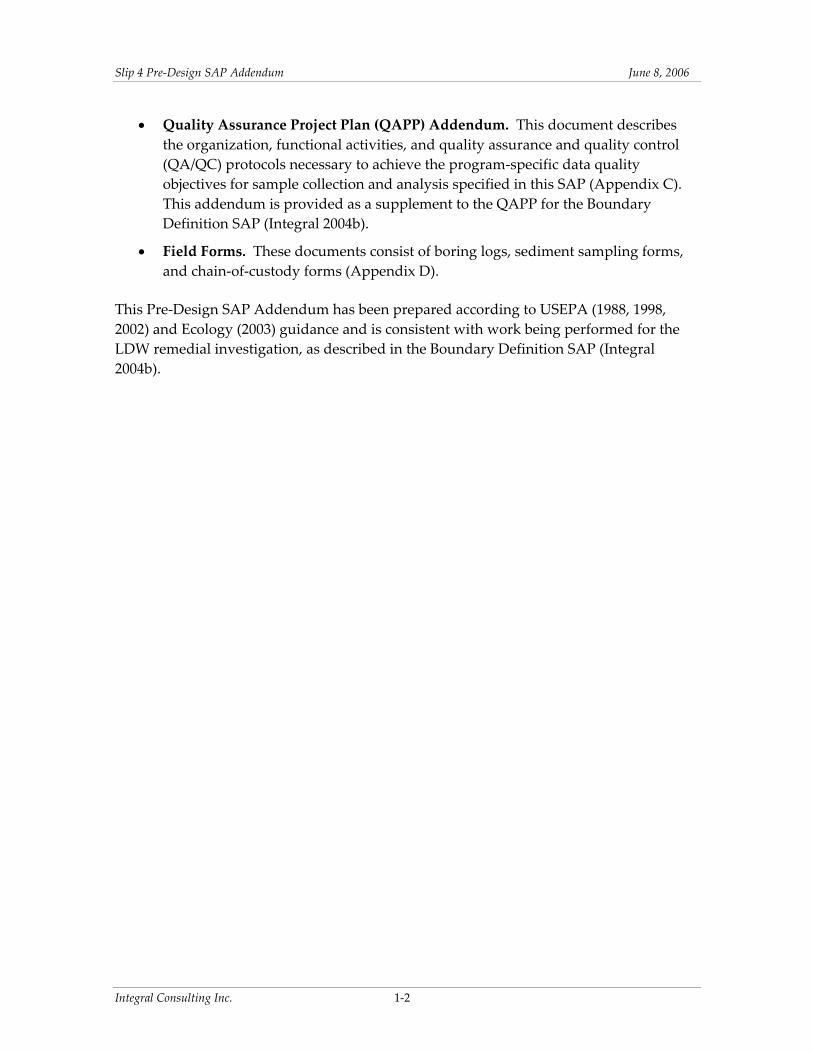
Slip 4 Pre‐Design SAP Addendum June 8 2006
Resource Conservation and Recovery Act (RCRA) Subtitle D solid waste landfill (Integral 2006) However additional analyses are needed to determine whether the material will qualify as a Washington State‐regulated dangerous waste Testing to determine the materialrsquos dangerous waste status will require bulk analysis and potentially Toxicity Characteristic Leaching Procedure (TCLP) analyses
In addition federal regulations under the Toxic Substances Control Act (TSCA) regarding the disposal of remediation waste with PCB concentrations ge50 mgkg may apply to sediment in a limited area at the head of the slip in the vicinity of the historical sampling station SL4‐6A Total PCB concentrations of 150 mgkg were detected in the 0ndash60 cm sample interval at this location in 1990 (Landau 1990) Additional sediment samples are needed to determine if a definable area exists where PCB concentrations are greater than 50 mgkg If so the design will evaluate if it is practicable for the material excavated from this area to be segregated during construction (Integral 2006)
2234 Cap Geotechnical Characterization
Capping of in situ surface sediment is planned for the southern portion of the removal area (Integral 2006) Samples for geotechnical analysis will be collected to determine the load‐bearing and consolidation properties of the sediment (Table 2‐1) These data will provide strength and index properties of the underlying sediment and will be used in the design to define any limitations on cap placement rates or thicknesses support slope stability evaluations and predict the expected consolidation of the material beneath the cap
23 SAMPLING DESIGN AND RATIONALE
This section describes the sampling strategy developed to address the identified pre‐design data gaps Additional investigations are needed to characterize overall field conditions surface and subsurface sediment seep water and bank soil The types of samples required the rationale and analyses are listed in Table 2‐1 The proposed subsurface core and bank sample and surface grab sample location coordinates are listed in Table 2‐2
231 Field Conditions Survey
A survey of current field conditions at the slip will be conducted during a very low tide In particular the extent and types of debris visible in the slip will be noted private outfalls will be photographed and attempts will be made to locate the East Marginal Way PS EOF Additionally the locations of seeps observed during the field survey will be noted to identify the seeps to be sampled
Integral Consulting Inc 2‐6
Slip 4 Pre‐Design SAP Addendum June 8 2006
In the under‐pier riprap area the presence or absence of fine‐grained deposits will be assessed to provide information for the under‐pier cap design Three transverse sections from approximately 0 ft mean lower low water (MLLW) to +12 ft MLLW will be visually and photographically documented for presence of fine‐grained material in riprap interstices
Geophysical features within the southern portion of the Zone 5 embankment on Boeing property will be visually evaluate and documented
In addition a structural survey of the Zone 4 bulkhead and Crowleyrsquos pier will be completed to document pre‐construction conditions of these structures This survey will be accomplished at a later date during the design process If the decision is made to remove a portion of the Crowley pier the structural survey will generate the information required for the design
232 Seep Water Sampling
Intertidal seep samples are planned to further quantify any PCB concentrations that may be present in discharges of upland groundwater to the slip The sediment cap can be designed using existing data from the LDW seep survey and established procedures in EPAUSACE (USEPA 1998) guidance for evaluating contaminant transport Based on the results of the LDW seep survey and current knowledge of the surrounding upland areas EPA and Ecology did not believe that additional seep sampling was necessary for source control determinations related to Slip 4 sediments However during development of the EECA the community voiced concerns that additional seep data should be collected (DRCC 2006) Based on the community concern additional seep samples will be collected This information will provide additional data that may be used in the sediment cap design
Seep sampling will consist of the collection of water samples from four to six seeps the locations of which will be selected based on field observations (see Table 2‐1) Seep sampling will be conducted along Zone 2 through 5 (see Figure 2‐2) where seeps are identified The procedures to be used for seep sample collection will generally follow methods used for previous seep sampling (Windward 2004a) discussed in Section 332 below Seep samples will be collected at low tide and submitted for laboratory analysis of PCBs as Aroclors and dissolved organic carbon (DOC) Field water quality parameters (temperature conductivity turbidity dissolved oxygen pH salinity and oxidation‐reduction potential) will be collected from the seep prior to sampling Water quality parameters will also be collected in the adjacent surface water at the time of sampling each seep
Integral Consulting Inc 2‐7
Slip 4 Pre‐Design SAP Addendum June 8 2006
233 Surface Sediment Sampling
Surface sediment data are needed to assess intertidal sediment conditions on the riprap bank of the Boeing property and will be used to verify the location of the removal boundary in that area Four intertidal locations (SG30 31 32 and 33) south of the removal boundary in Shoreline Zone 5 at elevations above 0 ft MLLW will be sampled the approximate locations are illustrated in Figure 2‐2 Analytical parameters for these surface samples will include PCBs as Aroclors and total organic carbon (TOC) (see Table 2‐1)
234 Subsurface Sediment and Soil Sampling
Subsurface sediment and soil data are needed to
1 Characterize removal area sediment physical properties for dredging evaluation
2 Characterize removal area sediment and soil for potential disposal under Washington State Dangerous Waste regulations
3 Characterize removal area sediment near the head of the slip that may require potential disposal under TSCA
4 Evaluate sediment‐bearing capacity and consolidation properties for the cap design
5 Provide data for slope stability (static and seismic) analyses in design
The samples that will address these needs are discussed in this section and presented in Table 2‐1
All subsurface soil samples will be characterized according to the Unified Soil Classification System (USCS) as per current annual American Society for Testing and Materials (ASTM) Methods (ASTM 2003) This visualmanual classification will occur in the field per ASTM D2488 and will be recorded on boring logs except where undisturbed samples for geotechnical characterization are submitted to the laboratory For those samples the laboratory will perform the USCS classification following ASTM D2487
2341 Removal Area Characterization
Shelby tube samples will be collected from HSA borings at three locations in the area to be dredged (Stations SC12 SC13 and SC16 see Figure 2‐2) which includes the historical sampling location SL4‐6A (SC16 Landau 1990) to evaluate sediment physical properties for remedial dredging evaluation and disposal requirements The cores will extend from the surface to 5 ft below the mudline (bml) Samples from three discrete intervals will be collected from each core using a Shelby tube sampler advanced with a barge‐mounted
Integral Consulting Inc 2‐8
Slip 4 Pre‐Design SAP Addendum June 8 2006
HSA drilling rig The samples will be extruded and classified according to the USCS in the field Samples from each interval will be submitted for analysis of geotechnical parameters including water content specific gravity grain‐size distribution Atterberg limits and TOC The target sample intervals are 0ndash2 ft 2ndash4 ft and 4ndash5 ft bml however the actual intervals will be selected in the field so that each sample represents only one type of sediment If the sediment is uniform the target intervals will be used If there is a change in sediment type (ie from plastic silt to sand) the sample intervals will be adjusted
To determine the disposal requirements for the sediment to be dredged one composite sample representing the total lengths of the three cores (SC12 SC13 and SC16 combined) will be collected This sample will be submitted for the following chemical analyses for disposal characterization PCBs SVOCs metals chlorinated pesticides extended diesel‐range total petroleum hydrocarbons (TPH‐Dx) gasoline‐range TPH (TPH‐G) and TOC A sample aliquot will be collected for TCLP analysis of SVOCs metals and chlorinated pesticides and will be archived at the laboratory TCLP analysis will be contingent on the results of dry‐weight analysis TCLP analysis will only need to be performed if the TCLP contaminants in the results from the total analysis are greater than or equal to 20 times the maximum concentration for toxicity characteristic regulatory levels (set forth in Table 1 of 40 CFR 26124) The ldquo20 times rulerdquo is allowable because of the sample dilution that is a component of the TCLP Method 1311 (Section 12 of this method) as is clarified in EPA 540‐R‐94‐005a
To determine the disposal requirements for the bank sediment to be removed one composite sample of soil from the surface to a depth of approximately 3ndash4 ft bgs will be collected from SB21 and one composite sample of soil from similar depths will be collected from SB22 and SB23 The bank borings or test pits will be logged and soils will be classified by the USCS in the field The two composite samples will be submitted for SVOCs metals chlorinated pesticides TPH‐Dx TPH‐G TOC and geotechnical analyses including water content specific gravity grain‐size distribution and Atterberg limits Sample aliquots collected for TCLP analysis of SVOCs metals and chlorinated pesticides will be archived at the laboratory and analysis will be contingent on the results of dry‐weight analysis
Subsurface sediment cores will be collected to determine if there is a definable and separately manageable area with PCB concentrations requiring TSCA disposal near the historical SL4‐6A location Five HSA cores extending from the surface to 5 ft bml will be collected at the historical location SL4‐6A (SC16) and surrounding locations (SC14 SC15 SC17 SC18 see Figure 2‐2) The samples will be collected in Shelby tubes extruded in the field and classified by USCS Composite samples representing the full core length will be collected from each core (ie five samples) and submitted for PCB analysis
Integral Consulting Inc 2‐9
Slip 4 Pre‐Design SAP Addendum June 8 2006
Archived sediment samples from vibracore SC01 collected in April 2004 will be submitted for analysis of the following geotechnical parameters to determine the dredgeability and handling characteristics of the sediment USCS classification water content TOC specific gravity grain‐size distribution and Atterberg limits A total of three archived samples from this core have been selected consisting of the 0ndash2 2ndash4 and 4ndash6 ft sample intervals
2342 Cap Geotechnical Characterization
Samples will be collected to evaluate consolidation of sediments underlying the cap as well as the bearing capacity and slope stability of the underlying sediments These data will be used in cap design An HSA equipped with both a Shelby tube sampler and a split‐spoon sampler will be advanced to 20 ft bml (sampling method to be determined based on observed soil conditions) Samples for geotechnical analysis will be collected in Shelby tubes at Stations SC19 SC20 SC21 and SC22 from 0 to 25 ft 25 to 50 ft and 50 to 75 ft bml The Shelby tubes will be capped in the field and submitted to the lab Split‐spoon samples will be taken from depths of 75 ft to the bottom of the boring at intervals of 25 ft logged in the field per USCS (ASTM D2488) and standard penetration test (SPT) blowcounts will be recorded No chemical or geotechnical analyses of these deeper sample intervals are planned but deeper samples will be archived for potential additional index testing Samples will be handled and shipped as described in Section 334
From each boring location one or two representative subsamples of fine‐grained sediment from the Shelby tubes will be analyzed by consolidation testing and unconsolidated undrained (UU) triaxial shear testing The actual sample intervals for consolidationstrength testing will be selected by the field coordinator when the samples are extruded at the lab and will be based on material characteristics These analyses will be run on an approximate 6‐in interval of sediments
In addition from each boring location one or two representative subsamples from the Shelby tubes will be analyzed for grain‐size distribution USCS classification in the laboratory (ASTM D2487) water content bulk density specific gravity Atterberg limits and TOC The above parameters will be analyzed on 1 or 2 samples per boring location even if it is determined that the sediments are not fine‐grained Additionally if noncohesive sand layers are encountered direct shear testing of those layers may be conducted
Integral Consulting Inc 2‐10
Slip 4 Pre‐Design SAP Addendum June 8 2006
3 FIELD SAMPLING PLAN
The following sections describe the project organization anticipated field event schedule field survey and sampling methods (and other procedures that will be followed during field operations) and the laboratory analyses to be conducted This information augments the field sampling plan provided in the Boundary Definition SAP (Integral 2004b)
31 PROJECT ORGANIZATION
This section presents the organizational structure for sampling and analysis activities associated with the Slip 4 pre‐design investigation including team organization and responsibilities fieldwork data management and laboratory analyses
311 Team Organization and Responsibilities
The organization and responsibilities of the investigation team remain as presented in the Boundary Definition SAP (Integral 2004b)
Ms Karen Keeley US EPA Region 10 is EPArsquos Remedial Project Manager for Slip 4 Ms Keeley is responsible for approving this SAP and any subsequent modifications
Ms Ginna Grepo‐Grove US EPA Region 10 is EPArsquos Quality Assurance Manager for this project Ms Grepo‐Grove will review and provide final approval of the QAPP Addendum and data quality report
Ms Jennie Goldberg is the Project Coordinator and the City of Seattlersquos Project Manager responsible for providing contract direction to Integral
Integral is responsible for implementing the sampling program and preparing the associated reports for US EPA Region 10 on behalf of the City of Seattle and King County
312 Integral Personnel
Integral project personnel for the Pre‐Design SAP Addendum are identified below
Integral Consulting Inc 3‐1
Slip 4 Pre‐Design SAP Addendum June 8 2006
Position Personnel Integral Principal in Charge Project Manager Field CoordinatorSafety Officer Project QA Coordinator Laboratory Coordinator and QA Manager Data Manager
Betsy Day David Schuchardt Jane Sund or Susan FitzGerald Reid Carscadden Maja Tritt Tom Schulz
The organizational structure of the lead sampling and analysis personnel and analytical laboratory is shown in Figure 1 of the QAPP Addendum (Appendix C) Project roles remain as outlined in the Boundary Definition SAP (Integral 2004b) with modifications reflected in Figure 1 of Appendix C
32 FIELD SAMPLING SCHEDULE
Field work for the pre‐design investigations is tentatively scheduled to begin in June 2006 and estimated to be completed in 5 days Many of the field tasks depend on tide levels and will be scheduled accordingly
33 FIELD SURVEY AND SAMPLING METHODS
The Slip 4 pre‐design elements include a field conditions survey seep water sampling intertidal surface sediment sampling subsurface bank soil sampling and subsurface sediment coring The methods to be used for the collection of these field data are described in this section All field documentation station positioning sample handling equipment decontamination waste disposal chain‐of‐custody and QC procedures will follow those described in the Boundary Definition SAP except where noted below (Integral 2004b) All field documentation will be recorded on either boring logs or sample collection forms (Appendix D) All sample locations will be located using a Differential Global Positioning System (DGPS) as described in the Boundary Definition SAP (Integral 2004b)
All field activities will be conducted in accordance with the site‐specific HSP that is provided in Appendix A
331 Field Conditions Documentation
The objectives of the field conditions documentation are to
bull Record visible shoreline and intertidal debris near and at the head of the slip
Integral Consulting Inc 3‐2
Slip 4 Pre‐Design SAP Addendum June 8 2006
bull Attempt to locate the East Marginal Way PS EOF
bull Photograph and document conditions of all public and private outfalls
bull Note locations of intertidal seeps
bull Visually evaluate and document geophysical features within the southern portion of the Zone 5 embankment on Boeing property
bull Document the presenceabsence of fine‐grained deposits within the riprap in the under‐pier area
The site survey will consist of notes regarding the types locations and approximate quantities or areas of intertidal debris the anticipated location of the East Marginal Way PS EOF the locations of intertidal seeps and site photographs Site photos will include overviews and close‐up views of the site conditions noted as appropriate The coordinates of the EOF outfall will be recorded In the under‐pier area three transverse sections from approximately 0 ft MLLW to +12 ft MLLW will be visually and photographically documented for presence of fine‐grained material in riprap interstices
A structural survey of the pier and Zone 4 bulkhead will be completed at a later date
332 Seep Water Sampling
Four to six seep samples will be collected at locations identified in the field conditions survey Seeps with the highest visually apparent flow rates will be targeted for sampling Insufficient flow from some seeps may limit the total number of seep samples that can be collected
Seep water sampling will be conducted generally following the methods of Windward (2004a) Windwardrsquos QAPP identified stainless‐steel PushPoint mini‐piezometers developed and sold by MHE Products as the preferred sampling method and also identified three alternative sampling methods if the piezometers yielded high turbidity or insufficient flow
1 Placement of an appropriate sampling container directly under an actively flowing seep from a moderate‐ to steep‐sloping embankment
2 Placement of a glass funnel Teflonreg sheeting andor Teflonreg tubing as appropriate below seeps where water cannot be collected directly under the flow Pre‐assigned pre‐cleaned funnels sheeting and tubing will be used at each sampling location to avoid contamination from other locations Sampling equipment will be pre‐cleaned by Frontier as described in EPA Method 1669 (USEPA 1996)
Integral Consulting Inc 3‐3
Slip 4 Pre‐Design SAP Addendum June 8 2006
3 Excavating a pit in the sediment lining the pit with a stainless‐steel bowl allowing it to fill with seep water and dipping a pre‐cleaned glass beaker in the bowl to collect the seep water
The actual field sampling results from the Windward (2004a) sampling effort yielded insufficient flow at the seep location in Slip 4 (Seep 10) and the actual sampling method previously used in Slip 4 was the glass funneltubing alternative method described in the second bullet above
For this investigation the piezometer method is not proposed based on the previous experience in Slip 4 The preferred method for this investigation is the third alternative method described above This method is preferred over the funnel and tube method because it allows continuous readings of conventional water quality parameters prior to and during sampling provides a flow‐through cell for accurate measurement of conventional water quality parameters and minimizes sample disturbance such as changes in oxidation‐reduction potential
A small depression will be dug into the sediment immediately downgradient of the seep so that the seep flow will pool in the depression alternatively the flow may be directed into a decontaminated container inserted into the depression Measurements of water quality parameters (temperature conductivity turbidity dissolved oxygen pH salinity and oxidation‐reduction potential) will be collected from the pool of seep discharge the parameter readings will be allowed to equilibrate prior to recording Measurements will be recorded on the water sample collection form (Appendix D) The seep samples will be collected from the depression using a pre‐cleaned glass beaker or a peristaltic pump with attached dedicated disposable tubing Care will be taken to minimize the entrainment of sediment into the collected seep water Samples will be collected at low tide and at a period when minimum salinity is observed in the discharge to obtain a sample that is most representative of groundwater discharge Samples will be filtered in the field using a 1‐μm glass fiber filter Only filtered samples will be collected since any sediment entrained by the sampling method (even at low turbidity readings) could result in a high biased analytical result The filtered samples will be submitted for PCB and DOC analysis
Measurements of water quality parameters (temperature conductivity turbidity dissolved oxygen pH salinity and oxidation‐reduction potential) will also be collected from adjacent surface water at the time of sample collection at each seep
333 Sediment and Soil Sampling
The equipment and procedures that will be used to collect surface and subsurface sediment samples are discussed in the following sections Field documentation of sample collection will be recorded on either boring logs or sedimentsoil collection forms
Integral Consulting Inc 3‐4
Slip 4 Pre‐Design SAP Addendum June 8 2006
(Appendix D) Photographs will be taken of each sampling interval in the subsurface samples as well as from the individual sampling pits
3331 Surface Sediment Sampling
The surface sediment samples (0ndash10 cm) will be collected during low tide from intertidal Stations SG30 through SG33 using stainless‐steel bowls and spoons The surface sediment will be submitted for PCB and TOC analyses
3332 Subsurface Sediment and Soil Sampling
All subsurface soil samples will be characterized according to the USCS The Visual Manual Method (ASTM D2488) will be used in the field and will be recorded on boring logs except where undisturbed samples for geotechnical characterization are submitted to the laboratory For those samples the laboratory will perform the USCS classification following ASTM D2487 Samples will be handled and shipped as described in Section 334
Samples for Removal Area Characterization
Subsurface sediment cores for the dredge area characterization will be collected using Shelby tube samplers advanced through HSA borings from a barge‐mounted drill rig The proposed borehole locations are shown in Figure 2‐2 Samples will be collected from 0 to 5 ft bml at each location according to the SOP for HSAShelby tube sampling (SOP 6 Appendix B) The core intervals will be sampled discretely or composited per the requirements at each station The cores will be subsampled according to two to three different schemes as discussed below
Sediment cores from seven locations will be used to characterize sediment in the area to be dredged The cores will be subsampled into three sample intervals as described in Section 2 These discrete samples will be analyzed for geotechnical parameters as follows
bull Nine subsamples from SC12 SC13 and SC16 will be analyzed for grain‐size distribution water content specific gravity and Atterberg limits
Six samples will be submitted for chemical analysis to evaluate disposal requirements as follows
bull One composite sample representing the entire recovered lengths of cores from SC12 SC13 and SC16 will be submitted for chemical analysis to evaluate whether the material will require disposal as a Washington State Dangerous Waste Analysis of this sample will include PCBs chlorinated pesticides SVOCs metals
Integral Consulting Inc 3‐5
Slip 4 Pre‐Design SAP Addendum June 8 2006
TPH‐Dx TPH‐G TOC and TCLP analysis for SVOCs chlorinated pesticides and metals
bull Five samples each representing the entire recovered lengths of one of five discrete cores from Stations SC14 through SC18 near the head of the slip will be submitted for PCB analysis to determine if segregation of an area potentially requiring disposal under TSCA regulations is practicable
Bank material in the removal areas will be sampled and submitted for chemical analysis to evaluate whether the material will require disposal as a Washington State Dangerous Waste These bank samples will be collected from hand augers andor hand‐dug test pits advanced to approximately 3ndash4 ft bgs
bull One composite sample will be collected from SB21 representing the approximate 0ndash4 ft depth interval to be removed
bull One composite sample will be collected of material from SB22 and SB23 representing the approximate 0ndash4 ft depth interval to be removed
Chemical analysis of these bank samples will include PCBs chlorinated pesticides SVOCs metals TPH‐Dx TPH‐G TOC and TCLP analysis for SVOCs chlorinated pesticides and metals Geotechnical analyses for these samples will include grain‐size distribution water content Atterberg limits and TOC Due to the widespread occurrence of riprap andor buried debris it is anticipated that hand‐dug test pits (advanced using a shovel) will likely be necessary and locations may need to be adjusted in the field The cores or test pits will be logged and classified following ASTM D2488 The test pits will be logged from the excavated test pit sidewall
Cap Geotechnical Characterization
Subsurface sediment cores for capping geotechnical characterization will be collected using Shelby tubes and split‐spoon samplers advanced through HSAs following the SOP for Shelby Tube Sampling (SOP 6 Appendix B) The samples will consist of undisturbed Shelby tubes collected from the intervals described in Section 2 at Stations SC19 SC20 SC21 and SC22 The undisturbed Shelby tubes will be sealed and submitted to the analytical lab and up to two sample intervals from each boring will be analyzed for consolidation testing The sample intervals for lab testing will be determined by the Integral Field Coordinator at the lab Fine‐grained sediment subsamples will be analyzed by consolidation testing and UU triaxial shear grain‐size distribution water content bulk density specific gravity Atterberg limits and TOC The lab will also record the USCS classification of the undisturbed samples
Integral Consulting Inc 3‐6
Slip 4 Pre‐Design SAP Addendum June 8 2006
The deeper sample intervals from these borings (to 20 ft bml) will be continuously sampled using a split‐spoon sampler logged in the field per USCS and SPT blowcounts will be recorded
Archived Samples
Three archived samples from SC01 collected in 2004 will be analyzed for grain‐size distribution USCS classification water content and Atterberg limits
334 Sample Handling and Transport
Sample jars coolers and packaging material will be supplied by the analytical laboratory Details on the numbers and type of sample containers are provided in the QAPP Addendum (Appendix C) Seep water samples bank subsurface soil samples surface sediment samples and disturbed subsurface sediment samples will be handled and transported in accordance with the procedures in the Boundary Definition SAP (Integral 2004b)
Undisturbed Shelby tube samples will be handled following ASTM D3213 Standard Practice for Handling Storing and Preparing Soft Undisturbed Marine Soil This standard covers the methods for projectcruise reporting and handling transporting and storing soft cohesive undisturbed marine soil The tube ends of the undisturbed Shelby tube samples will be sealed in the field as per SOP 6 (see Appendix B) to prevent leakage of pore water The tubes will be maintained in a vertical orientation and transported to the laboratory with minimal disturbance
335 Equipment Decontamination
The handcores will be rinsed with site water and washed with Liqui‐noxTM detergent prior to use and between sampling stations Decontamination of stainless‐steel bowls and spoons will also be performed before using sampling equipment at each station using the following process
bull Rinse with site water bull Wash with Liqui‐noxTM bull Double rinse with distilled water bull Rinse with deionized water bull Rinse with methanol bull Final rinse with deionized water
If a residual petroleum sheen remains on the sampling equipment or is difficult to remove using the standard decontaminations procedures above a final hexane rinse may be added
Integral Consulting Inc 3‐7
Slip 4 Pre‐Design SAP Addendum June 8 2006
Sample equipment will be kept wrapped in aluminum foil until time for use To minimize sample cross‐contamination disposable gloves will be replaced between stations
336 Investigation-Derived Waste
Investigation‐derived waste will be managed as described in the Boundary Definition SAP (Integral 2004b)
34 FIELD QUALITY CONTROL SAMPLES
QC requirements will be instituted during field sampling laboratory analysis and data management to ensure that the data quality objectives from Integral (2004b) are met Detailed information on QAQC procedures limits and reporting are described in detail in the QAPP (Integral 2004b) and QAPP Addendum (Appendix C)
Field QC samples will be collected as specified in the Boundary Definition SAP (Integral 2004b) with the exception that field replicates will only be collected during seep sampling Field QC samples will include field split samples (for surface sediment sampling) and equipment rinsate blanks (for seep sampling and surface sediment sampling) The types and numbers of QC samples that will be collected are listed in Table 4 of the QAPP Addendum (Appendix C)
35 LABORATORY ANALYSES
Laboratory analyses will be performed according to the Boundary Definition QAPP (Integral 2004b) and the QAPP Addendum (Appendix C)
Integral Consulting Inc 3‐8
Slip 4 Pre‐Design SAP Addendum June 8 2006
4 DATA MANAGEMENT AND REPORTING
During field laboratory and data evaluation operations effective data management is the key to providing consistent accurate and defensible data and data products The management and reporting of field and laboratory data will generally follow the procedures outlined by Integral (2004b) Changes or additions to those procedures based on the specific requirements of this FSP are discussed in the following sections
41 SAMPLE NUMBERING
According to Integral (2004b) all samples will be assigned a unique identification code based on a sample designation scheme designed to suit the needs of the field personnel data management and data users Sample identifiers will consist of two components separated by dashes The first component is SL4 to identify the data as originating in Slip 4 The second part will contain the following abbreviations for the sample type followed by the sample number
SB = subsurface bank soil composite sample CC = subsurface sediment core composite sample SC = subsurface core sample SG = surface grab sample SP = seep water sample
All station IDs will be numbered sequentially Surface and subsurface stations will continue the numbering scheme begun during the 2004 sampling (Integral 2004a) Composite core samples and seep samples will each be numbered sequentially starting with 01
Subsurface core samples will also have a letter that is placed after the sample number to designate the sample horizon in the core ldquoArdquo will be used to indicate the top interval (ie 0‐ to 2‐ft horizon) All subsequent (deeper) sample intervals will be indicated in alphabetical order (ldquoBrdquo 2ndash4 ft ldquoCrdquo 4ndash5 ft) Core samples collected from the full length of the core will be indicated by ldquoXrdquo
Seep water samples and composite core samples will be numbered sequentially
Some examples of sample labels include
bull SL4‐SB02 Second composite subsurface bank soil sample the stations comprising this composite will be noted in the field log book
Integral Consulting Inc 4‐1
Slip 4 Pre‐Design SAP Addendum June 8 2006
bull SL4‐CC01 First composite sediment core sample the core stations comprising this composite will be noted in the field log book
bull SL4‐SC14C Core sample from the 4‐ to 5‐ft horizon at Station 14
bull SL4‐SC15X Sample representing the full length of the core collected at Station 15
bull SL4‐SG32 Surface grab sample from intertidal Station 32
bull SL4‐SP01 First seep water sample station
42 LABORATORY DATA
Laboratory data reporting procedures will follow those of the Boundary Definition SAP (Integral 2004b)
43 DATA MANAGEMENT
Data management procedures will follow those of the Boundary Definition SAP Integral will continue to use the Environmental Quality Information System (EQuIS) in conjunction with the ArcView 9 geographic information system (GIS) tools to manage summarize and report the generated data Pre‐design data will be submitted electronically to EPA in the SEDQUAL format
44 DATA REVIEW AND REPORTING SCHEDULE
Data validation procedures will follow those called for in the Boundary Definition SAP (Integral 2004b) The results of this pre‐design investigation sampling will be presented in a Pre‐Design Sampling Data Report that will be an appendix to the 60 Design Documents for the Slip 4 Early Action currently scheduled for fall 2006 Information to be included in the Data Report will include but is not limited to
bull Field methods and any deviations from the SAP bull Field change requests bull Actual sample locations bull Laboratory analysis results bull Data validation reports bull Core logs bull Sample description forms bull Photodocumentation bull Description of geophysical features on Zone 5 embankment bull Location of the East Marginal Way PS EOF outfall
Integral Consulting Inc 4‐2
Slip 4 Pre‐Design SAP Addendum June 8 2006
bull Summary of under‐pier sediment accumulations in riprap interstices bull Engineerrsquos estimate of debris types and quantities
Integral Consulting Inc 4‐3
Slip 4 Pre‐Design SAP Addendum June 8 2006
This page intentionally left blank
Integral Consulting Inc 4‐4
Slip 4 Pre‐Design SAP Addendum June 8 2006
5 REFERENCES
ASTM 2003 Annual Book of ASTM Standards Volume 0408 American Society for Testing and Materials Philadelphia PA
DRCC 2006 Comment Letter Re Draft Lower Duwamish Waterway Slip 4 Early Action Area EECA January 6 2006 Duwamish River Cleanup Coalition Seattle WA
Ecology 2003 Sediment Sampling and Analysis Appendix Guidance on Development of Sediment Sampling and Analysis Plans Meeting the Requirements of the Sediment Management Standards PTI Environmental Services Bellevue WA and Washington Department of Ecology Olympia WA
Ecology 2005 Memorandum Re Slip 4 Upland Soil and Sediment PCB Investigation August 22 2005 Prepared by Sunny Becker Washington Department of Ecology Olympia WA
Integral 2004a Lower Duwamish Waterway Slip 4 Early Action Area Cruise and Data Report Prepared for City of Seattle and King County WA Integral Consulting Inc Mercer Island WA
Integral 2004b Lower Duwamish Waterway Slip 4 Early Action Area Sampling and Analysis Plan for Boundary Definition Prepared for City of Seattle and King County WA Integral Consulting Inc Mercer Island WA
Integral 2006 Lower Duwamish Waterway Slip 4 Early Action Area Engineering EvaluationCost Analysis Prepared for City of Seattle and King County WA Integral Consulting Inc Mercer Island WA
Landau 1990 Environmental Site Assessment First Interstate Bank of Washington Property 7400 8th Ave S amp 7343 E Marginal Way S Prepared for The Boeing Company Seattle WA Landau Associates Inc Edmonds WA
Schmoyer B 2006 Personal Communication (email of January 23 2006 to V Fagerness Integral Consulting Inc Olympia WA regarding modifications to outfall names) Seattle Public Utilities Seattle WA
SEA 2004 Lower Duwamish Waterway Slip 4 Early Action Area Summary of Existing Information and Identification of Data Gaps Prepared for City of Seattle and King County WA Striplin Environmental Associates Olympia WA
Integral Consulting Inc 5‐1
Slip 4 Pre‐Design SAP Addendum June 8 2006
USEPA 1988 Guidance for Conducting Remedial Investigations and Feasibility Studies under CERCLA Interim Final OWSER Directive 93553‐01 EPA 540‐G‐89‐004 US Environmental Protection Agency Office of Emergency and Remedial Response Washington DC
USEPA 1998 Assessment and Remediation of Contaminated Sediments (ARCS) Program Guidance for In‐Situ Subaqueous Capping of Contaminated Sediments EPA 905‐B96‐004 Prepared by US Army Corps of Engineers (Michael Palermo Jan Miller) and Danny D Reible Louisiana State University Great Lakes National Program Office Chicago IL
USEPA 2002 Guidance on Quality Assurance Project Plans EPA QAG‐5 EPA240R‐02009 US Environmental Protection Agency Office of Environmental Information Washington DC
USEPA 2006 Action Memorandum for Non‐Time Critical Removal Action at the Slip 4 Early Action Area of the Lower Duwamish Waterway Superfund Site Seattle Washington dated May 3 2006 US Environmental Protection Agency Region 10 Seattle WA
Windward 2004a Quality Assurance Project Plan Survey and Sampling of Lower Duwamish Waterway Seeps Prepared for Lower Duwamish Waterway Group for submittal to US Environmental Protection Agency and Washington State Department of Ecology Windward Environmental LLC Seattle WA
Windward 2004b Data Report Survey and Sampling of Lower Duwamish Waterway Seeps Prepared for Lower Duwamish Waterway Group for submittal to US Environmental Protection Agency and Washington State Department of Ecology Windward Environmental LLC Seattle WA
Integral Consulting Inc 5‐2
FIGURES
4 5
Slip 4
ChannelSlip 4 Channel
East Marginal
MapD
ocum
ent(
OP
rojec
tsDu
wami
sh_O
LYP
rojec
tsSli
p4_E
ECAS
iteLo
catio
nMap
mxd
) 52
4200
6--1
0141
1AM
Seattle Elliott Bay
Spokane St Bridge
Duwamish Waterway
RM 1
1st Ave S Bridge
RM 3 Slip 4
16th Ave S Bridge
Burien
RM 5
Turning Basin No 3
E Marginal Way Bridge
Tukwila
Figure 1-1Site Location Map
Slip 4 Pre-design SAP Map Feature Sources King County GIS Seattle Public Utilities USACE Ecology and others
18
14
16
12
16
12
12
14
AV
S
8TH
AV
S
Duwamish Waterway
Slip 4
8
14
12
1 0
16
2 0 222 4 2 6
28
3 0
32
20
8
1 4
10
1 2
1 8
24
18
16
2 2
16
14
1 4
1 4
12
1 6
1 8
14
18
14
1 4
10
1 6
1 6
1 8
1 2
1 6
16
1 8
1 8
1 8
8 TH
S OTHELLO ST NP RR
E MARGINAL WY S
Map
Doc
umen
t (O
Pro
ject
sD
uwam
ish_
OLY
Pro
ject
sSl
ip4_
EEC
AFi
gure
_2-5
_Hab
itat_
size
-AP
mxd
)4
112
006
--4
193
8 P
M
0 50 100 150 200 Feet deg NAD83
Slip 4 area Habitat Typesbeach
vegetation
DataQueryArea
Paved edgeBuildings
Bulkhead
shallow subtidal
berths amp docks wriprap
Dredging Areas - Post-1990
riprapmudflat
Figure 2-1 Site Features
Slip 4 Pre-design SAP Map Feature Sources King County GIS Seattle Public Utilities USACE Ecology and others
TABLES
Slip 4 Pre‐Design SAP Addendum June 8 2006
Table 2-1 Slip 4 Data Needs for Pre-Design Investigations Chemical Analyses Geotechnical Analyses
Purpose Matrix Sample Type Sampling Frequency Stations Analytes Samples Laboratory Field4 Samples Notes
Field Conditions Documentation
-- -- -- -- -- -- -- -- -- Debris tally photodocument locate EOF assess under-pier sediment presence document Zone 5 characteristics Structural survey of pier and Zone 4 bulkhead (at later date)
Seep Water Sampling (Bank)
Water Intertidal seep grab1 Estimated 4ndash6 locations field-determined
SP01 through SP06 PCBs DOC 4-6 -- -- NA Filtered samples Collect at low tide per LDW procedures Field WQ parameters measured prior to sampling 1
Intertidal Surface Sediments Verify Intertidal Boundary at Boeing Riprap
Sediment Intertidal surface grab (0-10 cm from spoonbowl)
4 locations south of boundary above 0 ft MLLW
SG30 SG31 SG32 SG33
PCBs TOC 4 -- -- 0 Requested by EPA
Intertidal and Subtidal Subsurface Sediments Sediment Disposal Characterization - TSCA Remediation Waste
Sediment Intertidal HSAShelby tubes 5 ft deep
5 locations near SL4-6A one full-depth composite sample per core
Sediment Disposal Characterization -Washington State Dangeous Waste Dredgeability and Handling
Sediment Intertidal HSAShelby tubes 5 ft deep
3 locations in dredge area including one at SL4-6A Index properties on individual core segments Disposal characterization on one composited sample of all three 5-ft cores
Dredgeability and Handling Sediment Archived cores Archived sediment sample SC-01 0ndash2ft 2ndash4ft 4ndash6 ft
Cap Design - Geotechnical Characterization of Underlying Sediments
Sediment HSA to 20 ft bml 0-25 ft 25-5 ft 5-75 ft Shelby tubes Split spoons to 20 ft
4 locations in cap area From each location analyze one or two representative 6-in intervals of fine-grained material for consolidation and strength Analyze one or two additional intervals for index properties Sampling intervals to be determined in field based on stratigraphy of the sample
SC14 SC15 SC16 SC17 SC18
PCBs 5 -- USCS classification 03 To assess need for segregation of TSCA material gt50 mgkg PCB
SC12 SC13 SC16 On Composite SVOCs inorganics chlorinated pesticides PCBs TOC TPH-G TPH-Dx TCLP (SVOCs inorganics pesticides) 6
1 On individual sample intervals2 water content specific gravity grain size Atterberg limits TOC
USCS classification 9
SC01 (archived) -- -- USCS classification5
water content specific gravity grain size Atterberg limits TOC
-- 3
SC19 SC20 SC21 SC22
-- -- On Shelby tubes Consolidation and UU Triaxial Shear (only fine-grained materials will be analyzed for these parameters) For the following analyses representative subsamples will be analyzed regardless of material type USCS classification5 water content bulk density specific gravity grain size Atterberg limits TOC
On Split Spoons USCS classification
8 Borings to 20 ft bml with both SPT and Shelby sampling Engineer to direct SPTShelby sampling Submit capped Shelby tubes to lab for subsampling Archive representative split spoon samples Up to 2 consolidation and triaxial samples may be submitted per boring on silt or clay units
Integral Consulting Inc 1 of 2
Slip 4 Pre‐Design SAP Addendum June 8 2006
Table 2-1 Slip 4 Data Needs for Pre-Design Investigations Chemical Analyses Geotechnical Analyses
Purpose Matrix Sample Type Sampling Frequency Stations Analytes Samples Laboratory Field4 Samples Notes
Bank Subsurface Soils
Zone 2 Bank ExcavationDisposal Characterization
Bank soils Composite soil sample from hand auger boring or hand-dug test pit
One composite sample from a boring (to 3ndash4 bgs) in Zone 2
SB21 SVOCs inorganics chlorinated pesticides PCBs TOC TPH-G TPH-Dx TCLP (SVOCs inorganics pesticides) 6
1 Water content specific gravity grain size Atterberg limits
USCS classification 1
Zone 3 4 5 Bank Excavation Disposal Characterization
Bank soils Composite soil sample from hand auger borings or hand-dug test pits
One composite sample from borings (to 3ndash4 bgs) in Zone 3 4 and 5
SB22 SB23 SVOCs inorganics chlorinated pesticides PCBs TOC TPH-G TPH-Dx TCLP (SVOCs inorganics pesticides)6
1 Water content specific gravity grain size Atterberg limits
USCS classification 1
Notes surface 1 Field water quality parameters will be measured before sampling at each seep location and in adjacent surface water Parameters include temperature conductivity turbidity dissolved oxygen pH salinity and oxidation-reduction potential 2 Sample target intervals will be from 0ndash2 ft below mudline (bml) 2ndash4 ft bml and 4ndash5 ft bml 3 Geotechnical analyses on samples from SC16 are included under Sediment disposal characterization - Washington State Dangerous Waste 4 USCS classification will be conducted in the field following ASTM D2488 Visual Manual Procedure 5 USCS classification will be conducted by the laboratory following ASTM D2487 6 TCLP aliquots to be archived for potential future analysis -- - not applicable
Integral Consulting Inc 2 of 2
Slip 4 Pre‐Design SAP Addendum June 8 2006
Table 2-2 Slip 4 Proposed Sample Locations for Pre-Design Investigations
Station ID Northing Easting
SC12 1992785071 1273514482 SC13 1993604344 1273429089 SC14 1994268725 1273459595 SC15 1994252542 1273498824 SC16 1994490406 1273482094 SC17 1994657131 1273501524 SC18 199465893 1273468952 SC19 1988678836 1273370448 SC20 1990483314 1273510154 SC21 1992283014 127340771 SC22 1993978931 1273521878 SB21 1994112452 1273410305 SB22 1992791657 1273582561 SB23 1988407995 1273394217 SG30 1988051522 1273345121 SG31 198791841 1273358284 SG32 1987818575 1273352892 SG33 1987902563 1273335606
Notes Horizontal Datum Washington State Plane Coordinate System North Zone (NAD 8391) US feet
Integral Consulting Inc 1
APPENDIX B
STANDARD
OPERATING
PROCEDURES
SOP‐6 Revision 52006
STANDARD OPERATING PROCEDURE 6
Hollow-Stem Auger DrillingSediment Sampling
Scope and Application
Soilsediment cores are collected to evaluate sediment at depths that greatly exceed those achieved by grab or other surface samplers The purpose of this standard operating procedure (SOP) is to define and standardize procedures for core collection using split‐spoon and Shelby tube samplers advanced through hollow‐stem auger borings following American Society for Testing and Materials (ASTM) Method D1586 and Method D1587 respectively The use of Shelby tube samplers or split‐spoon samplers is specified in the Slip 4 Pre‐Design Sampling and Analysis Plan Addendum (Integral 2006) Shelby tubes will be used to recover relatively undisturbed soil samples suitable for laboratory tests of engineering properties such as strength compressibility permeability and density
Required Equipment
bull Sampling and Analysis Plan (SAP)
bull Health and Safety Plan (HSP)
bull Site logbook and boring log
bull Indelible black‐ink pens and markers
bull Camera
bull Hollow‐stem auger drill rig
bull Driller and helper
bull Split‐spoon samplers (typically 2‐in diameter a larger 3‐in diameter 2‐ft‐length split‐spoon may be used to obtain more material from each depth interval)
bull Shelby tube samplers conforming to thin‐walled tube specifications outlined in ASTM D1587 with a 2‐ to 5‐in OD and 5 to 10 times the diameter in length Wax and end caps will also be provided for proper field sealing
bull Photoionization detector (PID)
bull Plastic sheeting
bull 55‐gallon drums (if required)
bull Insulated cooler(s) chain‐of‐custody seals Ziplocreg bags
bull Sample labels and appropriate documentation
Integral Consulting Inc 1
SOP‐6 Revision 52006
bull Assorted geology supplies (eg hand lens grain‐size card scales etc)
bull Decontamination equipment (SOP‐10)
Typical Procedures
1 Ensure underground utilities in vicinity of each boring location have been marked prior to mobilizing drill rig to site
2 Conduct daily site activityhealth and safety briefing
3 Calibrate field instrumentation if applicable
4 Record necessary data in field logbook
5 Obtain photograph(s) of site before drilling
6 Place plastic sheeting andor drums at drilling location to collect cuttings (if necessary)
7 Move equipment and supplies to drilling location
8 Set up decontamination and sampling stations
Split-Spoon Sampling
1 Obtain surface soil samples if required
2 Drill to first sampling depth as described in the SAP
3 Place decontaminated split‐spoon sampler on center rods
4 Drive split‐spoon sampler as described in ASTM Method D‐1586 Drive sampler to 18 inch or to refusal (no progress for 50 blows) Record blow counts on boring log form Retrieve sampler
5 Screen sampler with PID (if required)
6 Describe soil in accordance with ASTM D2488 on the boring log form
7 Composite soil sample as necessary If volatile organic compound (VOC) samples are to be collected collect VOC sample prior to describing soil
8 Continue drilling at next sample location Collect samples as outlined above
9 Label and manage sample containers in accordance with the site‐specific SAP section for shipping and handling of samples
10 Decontaminate sampling equipment in accordance with the site‐specific SAP
11 Document activities in site logbook
12 Backfill or grout borehole as required
Integral Consulting Inc 2
SOP‐6 Revision 52006
13 Move to next location
Shelby Tube Sampling
1 Obtain surface soil samples if required
2 Drill to first sampling depth as described in the SAP
3 Place decontaminated Shelby tube sampler on center rods
4 Drive Shelby tube sampler as described in ASTM Method D1587 Retrieve the sampling tube and remove the disturbed material from the top of the tube In addition remove 1 inch of soil from the base of the tube Place an impervious disk at both ends of the tube seal with a wax plug prior to shipment to the laboratory
5 If Shelby tubes are to be extruded in the field for composite sampling the driller will use a hydraulic extruder to obtain the sample The core is then described in accordance with ASTM Method D2488 on the boring log form Samples will then be composited as necessary for analysis
6 Screen sampler with PID (if required)
7 Label and manage sample containers in accordance with the site‐specific SAP section for shipping and handling of samples The sample tube should be packed in StyrofoamTM plugs or other cushioning material to prevent disturbance of the sample
8 Continue drilling to next sample location Collect samples as outlined above
9 Decontaminate sampling equipment in accordance with the site‐specific SAP section
10 Document activities in site logbook
11 Backfill or grout borehole as required
12 Move to next location
Reference
Integral 2006 Lower Duwamish Waterway Slip 4 Early Action Area Sampling and Analysis Plan for Boundary Definition Addendum Pre‐Design Investigation Sampling Prepared for Seattle City Light and King County Seattle WA Integral Consulting Inc Mercer Island WA
Integral Consulting Inc 3
APPENDIX C
QAPP ADDENDUM
LOWER DUWAMISH WATERWAY
SLIP 4 EARLY ACTION AREA
Quality Assurance Project Plan for Boundary Definition
Addendum Pre‐Design Investigation Sampling
Submitted to US Environmental Protection Agency Region 10
1200 Sixth Avenue Seattle WA 98101
Submitted by City of Seattle King County
Prepared by
7900 SE 28th Street Suite 300 Mercer Island WA 98040
June 8 2006
Pre‐Design QAPP Addendum June 8 2006
A PROJECT MANAGEMENT
A1 TITLE AND APPROVAL SHEET
QUALITY ASSURANCE PROJECT PLAN FOR BOUNDARY DEFINITION
PRE‐DESIGN INVESTIGATION SAMPLING ADDENDUM
LOWER DUWAMISH WATERWAY SLIP 4 EARLY ACTION AREA
SEATTLE WASHINGTON
Quality Assurance Project Plan Approvals
EPA Project Coordinator Karen Keeley Date
EPA QA Manager Ginna Grepo‐Grove Date
City of Seattle Project Manager Jennie Goldberg Date
Integral Principal in Charge Betsy Day Date
Integral Project Manager David Schuchardt Date
Integral Project QA Coordinator Reid Carscadden Date
ARI Project Manager Sue Dunnihoo Date
ARI QA Manager Dave Mitchell Date
Integral Consulting Inc ii
Pre‐Design QAPP Addendum June 8 2006
This page intentionally left blank
Integral Consulting Inc iii
Pre‐Design QAPP Addendum June 8 2006
A2 TABLE OF CONTENTS
A PROJECT MANAGEMENT ii A1 TITLE AND APPROVAL SHEET ii A2 TABLE OF CONTENTS iv A3 DISTRIBUTION LIST vii A4 INTRODUCTION AND PROJECT AND TASK ORGANIZATION1
A41 Introduction1 A42 Project and Task Organization1
A5 PROBLEM DEFINITION AND BACKGROUND1 A6 TASK DESCRIPTION 2 A7 QUALITY OBJECTIVES AND CRITERIA FOR MEASUREMENT DATA3
SECTION B DATA GENERATION AND ACQUISITION5 B1 SAMPLING PROCESS DESIGN 5 B2 SAMPLING METHODS7 B3 SAMPLE HANDLING AND CUSTODY7 B4 ANALYTICAL METHODS7 B5 QUALITY CONTROL 7
B51 Field Quality Control Samples 7
REFERENCES9
Integral Consulting Inc iv
Pre‐Design QAPP Addendum June 8 2006
LIST OF FIGURES Figure A4‐1 Organization Chart
LIST OF TABLES Table A4‐1 Project Team Contact Information Table A6‐1 Estimated Numbers of Pre‐Design Samples by Sample Type Table A6‐2 Target Analytes Methods and Method Reporting Limits for Pre‐Design
Investigation Samples Table A7‐1 Measurement Quality Objectives Table B2‐1 Sample Containers Preservation Holding Times and Sample Volume
Integral Consulting Inc v
Pre‐Design QAPP Addendum June 8 2006
ACRONYMS AND ABBREVIATIONS ARI Analytical Resources Inc ASTM American Society for Testing and Materials bml below the mudline DOC dissolved organic carbon DQOs data quality objectives EDD electronic data deliverables EECA engineering evaluationcost analysis EPA US Environmental Protection Agency EQuIS Environmental Quality Information System LDW Lower Duwamish Waterway MDLs method detection limits MQOs measurement quality objectives MRLs method reporting limits MS mass spectrometry PCB polychlorinated biphenyl PSEP Puget Sound Estuary Program QAPP quality assurance project plan QC quality control SAP sampling and analysis plan SVOCs semivolatile organic compounds TCLP Toxicity Characteristic Leaching Procedure TOC total organic carbon TPH total petroleum hydrocarbon TPH‐Dx extended diesel‐range total petroleum hydrocarbon TPH‐G gasoline‐range total petroleum hydrocarbon TSCA Toxic Substances Control Act USCS Unified Soil Classification System
Integral Consulting Inc vi
Pre‐Design QAPP Addendum June 8 2006
A3 DISTRIBUTION LIST
US EPA Region 10 Remedial Project Manager Karen Keeley
US EPA QA Manager Ginna Grepo‐Grove
City of Seattle Project Coordinator Jennie Goldberg
Integral Principal in Charge Betsy Day
Integral Project Manager David Schuchardt Integral Project QA Coordinator Reid Carscadden
Integral Field Coordinator Jane Sund or Susan FitzGerald
Integral Laboratory Coordinator amp QA Manager Maja Tritt Integral Data Manager Tom Schulz
ARI Project Manager Sue Dunnihoo
ARI QA Manager Dave Mitchell
Integral Consulting Inc vii
Pre‐Design QAPP Addendum June 8 2006
A4 INTRODUCTION AND PROJECT AND TASK ORGANIZATION
A41 Introduction
This quality assurance project plan (QAPP) addendum describes procedures that will be used to complete a pre‐design investigation to characterize seep water sediment and bank soil in the Slip 4 Early Action Area of the Lower Duwamish Waterway (LDW) This addendum supplements the Boundary Definition QAPP (Integral 2004a) The Boundary Definition QAPP describes procedures and requirements for the generation of data of documented acceptable quality that will be used for the pre‐design investigation This Pre‐Design QAPP Addendum addresses procedures that will be used for the pre‐design investigation that are not described in the Boundary Definition QAPP
Supplemental information to Sections A and B of the Boundary Definition QAPP is provided in this Pre‐Design QAPP Addendum Special training and certification and documents and records are described in Sections A8 and A9 respectively of the Boundary Definition QAPP and are not addressed further in this QAPP addendum
Procedures for project assessment and oversight will be completed as described in Section C of the Boundary Definition QAPP
All data for organic inorganic and conventional analytes including total solids used for dry‐weight conversions will be verified and validated Data for geotechnical characteristics do not require validation because of the mechanical nature of these tests Data verification and validation and data quality assessment procedures will be completed as described in Section D of the Boundary Definition QAPP
A42 PROJECT AND TASK ORGANIZATION
The organizational structure for this project is illustrated in Figure A4‐1 Contact information related to the pre‐design investigation is provided in Table A4‐1 of this QAPP addendum Project and quality assurance responsibilities are described in detail in Section 31 of the Boundary Definition sampling and analysis plan (SAP) and Pre‐Design SAP Addendum (Integral 2004b and 2006b respectively)
A5 PROBLEM DEFINITION AND BACKGROUND
The primary objective of this Slip 4 pre‐design investigation is to fill identified data gaps to support the design of the removal action alternative recommended by the City of Seattle and King County as presented in the engineering evaluationcost analysis (EECA) (Integral 2006a) Data will be collected to support the following activities
Integral Consulting Inc 1
Pre‐Design QAPP Addendum June 8 2006
bull Verification of the removal boundary bull Characterization of seep water bull Dredging evaluation of the removal area bull Characterization of removal area sediment and bank soil for disposal bull Geotechnical characterization of the capping area
Sampling activities will include collection of seep samples surface and subsurface sediment samples and subsurface bank samples Details are provided in Sections 21 and 22 of the Pre‐Design SAP Addendum
A6 TASK DESCRIPTION
The tasks to be completed for this project include fieldwork laboratory analyses data quality evaluation data management data analysis and report preparation The Slip 4 pre‐design elements include a field conditions survey seep water sampling intertidal surface sediment sampling subsurface bank soil sampling and subsurface sediment coring The methods to be used for the collection of these samples are described in Section 33 of the Pre‐Design SAP Addendum All field documentation station positioning sample handling equipment decontamination waste disposal chain‐of‐custody and quality control procedures will follow those described in the Boundary Definition SAP (Integral 2004b) except where noted in the Pre‐Design SAP Addendum
Integral will collect the various sediment bank soil and seep water samples and prepare samples for delivery to the laboratory Susan FitzGerald or Jane Sund of Integral will serve as field coordinator and will assume custody of cores and samples as they are collected A list of samples and analyses is provided in Table A6‐1 Sample locations are provided in Figure 2‐2 of the Pre‐Design SAP Addendum (Integral 2006b)
Samples will undergo chemical and geotechnical testing by Analytical Resources Inc (ARI Seattle WA) for analytes listed in Table A6‐2 Analyses will be completed using US Environmental Protection Agency (EPA) American Society for Testing and Materials (ASTM) and Puget Sound Estuary Program (PSEP) methods (USEPA 2003 PSEP 1986 1997ab ASTM 2003) as indicated in Table A6‐2 Full laboratory data reports will be provided in hardcopy and electronic data deliverables (EDDs) will be provided in spreadsheet format as required for importing into the database The Environmental Quality Information System (EQuIS) database application will be used to manage the field and laboratory data Data will also be submitted electronically to EPA in SEDQUAL format
Data verification will be completed by Integral for data generated in the field and by ARI for data generated at the laboratory The accuracy and completeness of the final database will be verified by Integral Data validation and data quality assessment will be
Integral Consulting Inc 2
Pre‐Design QAPP Addendum June 8 2006
completed by an independent validation firm which will be selected at a later date The validation firm will also complete data verification (ie verifying that analytical procedures and calculations were completed correctly and checking transcriptions of the laboratory data) for the first data package for each analysis as part of the full validation that will be completed for these packages
The results of the Pre‐Design SAP Addendum field sampling will be presented in the 60 Design Documents for the Slip 4 Early Action currently scheduled for completion in fall 2006
The start date for field sampling will be determined following EPA approval of the project SAP and QAPP addenda and pending property access permission from property owners Currently it is anticipated that field sampling will begin in June 2006 The field and reporting schedules are discussed further in Sections 32 and 44 respectively of the Pre‐Design SAP Addendum
A7 QUALITY OBJECTIVES AND CRITERIA FOR MEASUREMENT DATA
Data quality objectives (DQOs) for the pre‐design investigation are described in Section A7 of the Boundary Definition QAPP Target method reporting limits (MRLs) and method detection limits (MDLs) for this project are summarized in Table A6‐2 Measurement quality objectives (MQOs) for this project are summarized in Table A7‐1 Analyte concentrations for this project will be reported to the MDL as described in the Boundary Definition QAPP
Integral Consulting Inc 3
Pre‐Design QAPP Addendum June 8 2006
This page intentionally left blank
Integral Consulting Inc 4
Pre‐Design QAPP Addendum June 8 2006
SECTION B DATA GENERATION AND ACQUISITION
B1 SAMPLING PROCESS DESIGN
This section supplements Section B1 of the Boundary Definition QAPP The sampling effort for this study will include the collection of seep water surface sediment subsurface sediment and subsurface bank soil from Slip 4 in the LDW
Seep water will be collected as discrete samples from individual seep locations (to be determined in the field) Water quality parameters (conductivity turbidity temperature dissolved oxygen pH salinity and oxidation‐reduction potential) will be measured in the field at each seep and in adjacent surface water prior to sample collection Seep samples will be filtered in the field through 10‐μm glass filters and submitted for laboratory analysis for polychlorinated biphenyl (PCB) Aroclors and dissolved organic carbon (DOC)
Surface sediment samples will be collected from the 0ndash10 cm interval at four locations and will be analyzed for total organic carbon (TOC) and PCB Aroclors
All subsurface soil samples will be characterized according to the Unified Soil Classification System (USCS) as per current annual American Society for Testing and Materials (ASTM) Methods This visualmanual classification will occur in the field per ASTM D2488 and will be recorded on boring logs except where undisturbed samples for geotechnical characterization are submitted to the laboratory For those samples the laboratory will perform the USCS classification following ASTM D2487 Field USCS classification is not considered an ldquoanalysisrdquo in the QAPP
Sediment cores from 0 to 5 ft below the mudline (bml) will be collected from seven locations to characterize sediment in the area to be dredged Chemical analyses will be required on six samples as follows
bull One composite sample representing the entire 0‐ to 5‐ft lengths of cores from three of the locations will be submitted for chemical analysis to evaluate whether the material will require disposal as a Washington State Dangerous Waste Analysis of this sample will include PCB Aroclors chlorinated pesticides semivolatile organic compounds (SVOCs) metals extended diesel‐range total petroleum hydrocarbons (TPH‐Dx) gasoline‐range TPH (TPH‐G) and TOC An additional aliquot of this sample will be archived for potential future Toxicity Characteristic Leaching Procedure (TCLP) analyses for SVOCs chlorinated pesticides and metals
Integral Consulting Inc 5
Pre‐Design QAPP Addendum June 8 2006
bull Five samples representing the 0‐ to 5‐ft lengths of five discrete cores near the head of the slip will be submitted for PCB Aroclor analysis to determine if segregation of an area potentially requiring disposal under the Toxic Substances Control Act (TSCA) regulations is practicable
The cores will also be subsampled into three sample intervals (0ndash2 ft bml 2ndash4 ft bml and 4ndash5 ft bml) These discrete samples will be analyzed for geotechnical parameters as follows
bull Nine subsamples from three cores (SC12 SC13 and SC16) representing the area to be dredged will be analyzed for grain‐size distribution water content specific gravity Atterberg limits and TOC One of the cores in this group (SC16) is located in the potential TSCA area
bull Three archived samples from SC01 (0ndash2 ft 2ndash4 ft and 4ndash6 ft) collected in 2004 will be analyzed for grain‐size distribution water content USCS classification specific gravity Atterberg limits and TOC
Samples of bank soil from bank removal areas are needed to characterize the material for disposal Two composite samples will be collected using hand auger boring or hand dug test pit one sample from Zone 2 and one sample from Zones 3 4 and 5 These samples will be submitted for chemical and geotechnical analyses Chemical analytes will include PCB Aroclors chlorinated pesticides SVOCs metals TPH‐Dx TPH‐G TOC and TCLP analysis for SVOCs chlorinated pesticides and metals Samples collected for TCLP analysis of SVOCs metals and chlorinated pesticides will be archived at the laboratory and analysis will be contingent on the results of dry‐weight analysis TCLP analysis will only need to be performed when the TCLP contaminants in the results from the total analysis are greater than or equal to 20 times the maximum concentration for toxicity characteristic regulatory levels (set forth in Table 1 of 40 CFR 26124) The ldquo20 times rulerdquo is allowable because of the sample dilution that is a component of the TCLP Method 1311 (Section 12 of this method) as is clarified in EPA 540‐R‐94‐005a Geotechnical analyses will include grain‐size distribution water content specific gravity Atterberg limits and TOC
Sediment samples from four cores will be collected for geotechnical analyses to determine the consolidation properties strength and bearing capacity of the underlying sediments These samples will be analyzed by consolidation testing unconsolidated undrained (UU) triaxial shear grain‐size distribution USCS classification water content bulk density specific gravity Atterberg limits and TOC
Field quality control (QC) samples will be collected for chemical analysis as specified in the QAPP (Integral 2004a) with the exception that field duplicate cores will not be
Integral Consulting Inc 6
Pre‐Design QAPP Addendum June 8 2006
collected Field QC samples are described in Section 36 of the Boundary Definition SAP (Integral 2004b) and Section 34 of the Pre‐Design SAP Addendum (Integral 2006b)
B2 SAMPLING METHODS
This section supplements Section B2 of the Boundary Definition QAPP
Seep samples will be collected using either a funnel or peristaltic pump with attached dedicated disposal tubing Intertidal surface sediment will be collected using stainless‐steel bowls and spoons Subsurface sediment cores for dredge area characterization and for geotechnical evaluation will be collected using Shelby tubes and split‐spoon samplers advanced through hollow‐stem augers using a barge‐mounted drill rig Subsurface bank soil samples will be collected using hand augers or hand‐dug test pits Sampling methods are described in Section 33 of the Pre‐Design SAP Addendum Requirements for sample containers storage temperature and holding times for sediment and seep water samples are summarized in Table B2‐1 of this Pre‐Design QAPP Addendum
B3 SAMPLE HANDLING AND CUSTODY
Sample handling and custody procedures will be completed as described in Section 334 of the Pre‐Design SAP Addendum (Integral 2006b)
B4 ANALYTICAL METHODS
Analyses will be completed according to the methods provided in Table A6‐2 These methods will be modified in some cases as described in the Boundary Definition QAPP Sediment samples will be analyzed for SVOCs by full‐scan mass spectrometry (MS) Selected ion monitoring will not be used because the sensitivity of full‐scan MS is sufficient to meet the study objectives
B5 QUALITY CONTROL
Quality control samples will be prepared in the field and at the laboratories to monitor the bias and precision of the sample collection and analysis procedures Field quality control samples are described below Laboratory quality control will be completed as described in the Boundary Definition QAPP
B51 Field Quality Control Samples
Field QC samples for the pre‐design investigation will include field duplicates (for surface sediment sampling) field replicates (for seep sampling) and equipment rinse blanks (for
Integral Consulting Inc 7
Pre‐Design QAPP Addendum June 8 2006
seep and surface sediment sampling) Field QC samples will be collected at a minimum for seep and surface sediment samples at a frequency of 5 percent of the sample total The procedures for preparing field replicates duplicates and rinse blanks are presented in Section 36 of the Boundary Definition SAP (Integral 2004b) and Section 34 of the Pre‐Design SAP Addendum (Integral 2006b) Validation criteria and procedures for field QC samples are described in Sections D1 and D2 of the Boundary Definition QAPP (Integral 2004a)
Integral Consulting Inc 8
Pre‐Design QAPP Addendum June 8 2006
REFERENCES
ASTM 2003 Annual Book of ASTM Standards Volume 0408 American Society for Testing and Materials Philadelphia PA
Integral 2004a Lower Duwamish Waterway Slip 4 Early Action Area Quality Assurance Project Plan for Boundary Definition Prepared for Seattle City Light and King County Seattle WA Integral Consulting Inc Mercer Island WA
Integral 2004b Lower Duwamish Waterway Slip 4 Early Action Area Sampling and Analysis Plan for Boundary Definition Prepared for City of Seattle and King County WA Integral Consulting Inc Mercer Island WA
Integral 2006a Lower Duwamish Waterway Slip 4 Early Action Area Engineering EvaluationCost Analysis Submitted to US EPA Region 10 City of Seattle King County Seattle WA Integral Consulting Inc Mercer Island WA
Integral 2006b Lower Duwamish Waterway Slip 4 Early Action Area Sampling and Analysis Plan for Boundary Definition Addendum Pre‐Design Investigation Sampling Prepared for Seattle City Light and King County Seattle WA Integral Consulting Inc Mercer Island WA
Plumb Jr RH 1981 Procedures for Handling and Chemical Analysis of Sediment and Water Samples Technical Report EPACE‐81‐1 Prepared by Great Lakes Laboratory State University College at Buffalo Buffalo NY for the US Environmental Protection AgencyUS Army Corps of Engineers Technical Committee on Criteria for Dredged and Fill Material Published by the US Army Engineer Waterways Experiment Station CE Vicksburg MS
PSEP 1986 Puget Sound Estuary Program Recommended Protocols for Measuring Conventional Sediment Variables in Puget Sound Final Report TC‐3991‐04 Prepared for US Environmental Protection Agency Region 10 Seattle WA Tetra Tech and HRA Inc Bellevue WA (minor corrections April 2003)
PSEP 1997a Puget Sound Estuary Program Recommended Guidelines for Measuring Organic Compounds in Puget Sound Water Sediment and Tissue Samples In Recommended Protocols for Measuring Selected Environmental Variables in Puget Sound Puget Sound Action Team Olympia WA
Integral Consulting Inc 9
Pre‐Design QAPP Addendum June 8 2006
PSEP 1997b Puget Sound Estuary Program Recommended Quality Assurance and Quality Control Guidelines for the Collection of Environmental Data in Puget Sound In Recommended Protocols for Measuring Selected Environmental Variables in Puget Sound Puget Sound Action Team Olympia WA
USEPA 2003 SW‐846 On‐line Test Methods for Evaluating Solid Waste ‐PhysicalChemical Methods US Environmental Protection Agency httpwwwepagovepaoswerhazwastetestmainhtm Accessed January 8 2004
Windward 2004 Data Report Survey and Sampling of Lower Duwamish Waterway Seeps Prepared for Lower Duwamish Waterway Group for submittal to US Environmental Protection Agency and Washington State Department of Ecology Windward Environmental LLC Seattle WA
Integral Consulting Inc 10
FIGURE
EPA Region 10
Remedial Project Manager Karen Keeley
Principal In Charge Betsy Day
Project Manager Dave Schuchardt
Integral Laboratory Coordinator
amp QA Manager Maja Tritt
EPA QA Manger Ginna Grepo-Grove
Project QA Coordinator Ried Carscadden
Data Management Tom Schulz
Field Coordinator Jane Sund or Susan FitzGerald
City of Seattle
Project Coordinator Jennie Goldberg
Data Validation Firm
to be determined
Analytical Resources Inc
Project Manager Sue Dunnihoo
Cascade Drilling
Figure A4-1 Organization Chart
TABLES
Slip 4 Pre‐Design QAPP Addendum June 8 2006
Table A4-1 Project Team Contact Information
Organization EPA Region 10
Individual Karen Keeley Ginna Grepo-Grove
Project Role Project Coordinator QA Manager
Phone 206-553-2141 206-553-1632
Fax 206-553-0124 206-553-8210
Email KeeleyKarenepagov Grepo-GroveGinaepagov
City of Seattle Jennie Goldberg SCL Project Coordinator 206-684-3167 206-386-4589 jenniegoldbergseattlegov
Integral Consulting Betsy Day David Schuchardt Reid Carscadden Jane Sund or Susan FitzGerald Ian Stupakoff
Principal in Charge Project Manager Project QA Coordinator
Field Coordinator
Field Staff
206-957-0346 206-957-0350 206-957-0343 503-284-5545 ext15 or 206-957-0352 360-705-3534 360-259-2518
206-230-9601 206-230-9601 206-230-9601 503-284-5755 or 206-230-9601
360-705-3669
bdayintegral-corpcom dschuchardtintegral-corpcom rcarscaddenintegral-corpcom jsundintegral-corpcom sfitzgeraldintegral-corpcom istupakoffintegral-corpcom
Maja Tritt Tom Schulz
Laboratory CoordinatorQA Manager Data Manager
206-957-0353 360-705-3534 ext17
206-230-9601 360-705-3669
mtrittintegral-corpcom tschulzintegral-corpcom
Analytical Resources Inc (ARI)
Sue Dunnihoo Dave Mitchell
Laboratory Project Manager Laboratory QA Manager
206-695-6207 206-695-6205
206-621-7523 206-621-7523
suedarilabscom davemarilabscom
Integral Consulting Inc 1 of 1
Slip 4 Pre‐Design QAPP Addendum June 8 2006
Table A6-1 Estimated Numbers of Pre-Design Samples by Sample Type
Total Number Number of Field Field Equipment of Field
Sample Type and Analysis Samples1 Duplicates2 Replicates2 Rinse Blanks Samples
Seep WaterPCB Aroclors 4ndash6 0 1 1 6ndash8 DOC 4ndash6 0 1 1 6ndash8
Surface Sediment PCB Aroclors 4 1 0 1 6 Total Organic Carbon 4 1 0 NA 5
Subsurface Sediment PCB Aroclors 6 0 0 0 6 SVOCs 1 0 0 0 1 Metals 1 0 0 0 1 Chlorinated Pesticides 1 0 0 0 1 TPH-Dx 1 0 0 0 1 TPH-G 1 0 0 0 1 TCLP SVOCs 3 1 0 0 NA 1 TCLP Metals 3 1 0 0 NA 1 TCLP Chlorinated Pesticides 3 1 0 0 NA 1 Grain-Size Distribution 20 0 0 NA 20 Total Organic Carbon 20 0 0 NA 20 Water Content 20 0 0 NA 20 Bulk Density 8 0 0 NA 8 Specific Gravity 20 0 0 NA 20 Atterberg limits 20 0 0 NA 20 USCS Classification 4 11 0 0 NA 11 Consolidation 8 NA 0 NA 8 UU Triaxial Shear 8 NA 0 NA 8
Subsurface Sediment (Archived Analysis) Grain-Size Distribution 3 0 0 NA 3 Total Organic Carbon 3 0 0 NA 3 Water Content 3 0 0 NA 3 Bulk Density 0 0 0 NA 0 Specific Gravity 3 0 0 NA 3 Atterberg Limits 3 0 0 NA 3 USCS Classification 4 3 0 0 NA 3
Subsurface Bank Soil PCB Aroclors 2 0 0 0 2 SVOCs 2 0 0 0 2 Metals 2 0 0 0 2 Chlorinated Pesticides 2 0 0 0 2 TPH-Dx 2 0 0 0 2 TPH-G 2 0 0 0 2 TCLP SVOCs 3 2 0 0 NA 2 TCLP Metals 3 2 0 0 NA 2 TCLP Chlorinated Pesticides 3 2 0 0 NA 2 Grain-Size Distribution 2 0 0 NA 2
Integral Consulting Inc 1 of 2
Slip 4 Pre‐Design QAPP Addendum June 8 2006
Table A6-1 Estimated Numbers of Pre-Design Samples by Sample Type
Total Number Number of Field Field Equipment of Field
Sample Type and Analysis Samples1 Duplicates2 Replicates2 Rinse Blanks Samples
Total Organic Carbon 2 0 0 NA 2 Water Content 2 0 0 NA 2 Bulk Density 0 0 0 NA 0 Specific Gravity 2 0 0 NA 2 Atterberg Limits 2 0 0 NA 2
Notes DOC = dissolved organic carbon PCB = polychlorinated biphenyls SVOCs = semivolatile organic compounds TCLP = Toxicity Characteristic Leaching Procedure TPH-Dx = total petroleum hydrocarbons diesel- and oil-range1 Numbers are based on the Pre-Design SAP Addendum Integral 2006b Table 2-12 Duplicate replicate and rinsate samples will not be collected for waste disposal characterization samples 3 TCLP samples will be archived for potential future analysis 4 Only laboratory USCS Classification samples by ASTM D2487 are shown
Integral Consulting Inc 2 of 2
Slip 4 Pre‐Design QAPP Addendum June 8 2006
Table A6-2 Target Analytes Methods and Method Reporting Limits for Pre-Design Investigation Samples
Analyte Sample Preparation Method Sample Cleanup Method1 Analysis Method MDL MRL
Seep Water PCB Aroclors (ugL)
Dissolved Organic Carbon (mgL)
ARI Low Level (Modified EPA 3510)
EPA 4151
EPA 3660B (sulfur) EPA 3665A (acid)
EPA 3630C (silica gel) optional2
--
GCECD (EPA 8082)3
Direct combustion (EPA 4151)
0005
0018
001
002
Sediments and Bank Soils Conventional analytes
USCS Classification -- -- ASTM D-2487 -- --Grain Size ( dry wt) TOC ( dry wt)
----
----
PSEP (1986) Plumb (1981)
--0018
01 002
Geotechnical Charactersitics Atterberg limits ( moisture) Specific gravity (gcc) Water content (percent) Bulk density (gcc) Consolidation
----------
----------
ASTM D-4318 ASTM D-854
ASTM D-2216 ASTM D-2937
ASTM D-2435 Method B
----------
01 001 01 01 --
UU Triaxial Shear -- -- ASTM D-2850 -- --
PCB Aroclors (ugkg dry weight) ARI Low Level (EPA 3550B-mod) EPA 3660B (sulfur) optional2
EPA 3665A (acid) optional2 GCECD (EPA 8082)3 04 40
Pesticides (ugkg dry weight) 44rsquo-DDT 44rsquo-DDE 44rsquo-DDD 24rsquo-DDT 24rsquo-DDE 24rsquo-DDD Aldrin alpha-BHC beta-BHC delta-BHC gamma-BHC Oxychlordane alpha-chlordane gamma-chlordane cis-nonachlor
Sonication (EPA 3550B) Sonication (EPA 3550B) Sonication (EPA 3550B) Sonication (EPA 3550B) Sonication (EPA 3550B) Sonication (EPA 3550B) Sonication (EPA 3550B) Sonication (EPA 3550B) Sonication (EPA 3550B) Sonication (EPA 3550B) Sonication (EPA 3550B) Sonication (EPA 3550B) Sonication (EPA 3550B) Sonication (EPA 3550B) Sonication (EPA 3550B)
EPA 3660BEPA3630C EPA 3660BEPA3630C EPA 3660BEPA3630C EPA 3660BEPA3630C EPA 3660BEPA3630C EPA 3660BEPA3630C EPA 3660BEPA3630C EPA 3660BEPA3630C EPA 3660BEPA3630C EPA 3660BEPA3630C EPA 3660BEPA3630C EPA 3660BEPA3630C EPA 3660BEPA3630C EPA 3660BEPA3630C EPA 3660BEPA3630C
EPA 8081A EPA 8081A EPA 8081A EPA 8081A EPA 8081A EPA 8081A EPA 8081A EPA 8081A EPA 8081A EPA 8081A EPA 8081A EPA 8081A EPA 8081A EPA 8081A EPA 8081A
0199 0125 0095 0091 0033 0037 0044 0051 0091 0021 009
0123 0058 012 055
20 20 20 20 20 20 10 10 10 10 10 20 10 10 20
Integral Consulting Inc 1 of 4
Slip 4 Pre‐Design QAPP Addendum June 8 2006
Table A6-2 Target Analytes Methods and Method Reporting Limits for Pre-Design Investigation Samples
Analyte Sample Preparation Method Sample Cleanup Method1 Analysis Method MDL MRL
trans-nonachlor Sonication (EPA 3550B) EPA 3660BEPA3630C EPA 8081A 0024 20 Dieldrin Sonication (EPA 3550B) EPA 3660BEPA3630C EPA 8081A 0085 20 Endosulfan Sonication (EPA 3550B) EPA 3660BEPA3630C EPA 8081A 0063 10 Endosulfan II Sonication (EPA 3550B) EPA 3660BEPA3630C EPA 8081A 0125 20 Endosulfan sulfate Sonication (EPA 3550B) EPA 3660BEPA3630C EPA 8081A 0148 20 Endrin Sonication (EPA 3550B) EPA 3660BEPA3630C EPA 8081A 0082 20 Endrin aldehyde Sonication (EPA 3550B) EPA 3660BEPA3630C EPA 8081A 0184 20 Heptachlor Sonication (EPA 3550B) EPA 3660BEPA3630C EPA 8081A 0073 10 Heptachlor epoxide Sonication (EPA 3550B) EPA 3660BEPA3630C EPA 8081A 0054 10 Hexachlorobenzene Sonication (EPA 3550B) EPA 3660BEPA3630C EPA 8081A 0066 10 Methoxychlor Sonication (EPA 3550B) EPA 3660BEPA3630C EPA 8081A 112 100 Mirex Sonication (EPA 3550B) EPA 3660BEPA3630C EPA 8081A 0013 20 Toxaphene Sonication (EPA 3550B) EPA 3660BEPA3630C EPA 8081A 296 1000
Metals (mgkg) Arsenic EPA 3050 -- EPA 6010B 078 50 Cadmium EPA 3050 -- EPA 6010B 004 02 Chromium EPA 3050 -- EPA 6010B 009 05 Copper EPA 3050 -- EPA 6010B 006 02 Lead EPA 3050 -- EPA 6010B 011 20 Mercury EPA 7471A -- EPA 7471A 0003 005 Silver EPA 3050 -- EPA 6010B 004 03 Zinc EPA 3050 -- EPA 6010B 034 06
Semivolatiles (mgkg) 124-Trichlorobenzene EPA 3550B EPA 3640A EPA 8270C - PSEP (Full scan) 953 20 12-Dichlorobenzene EPA 3550B EPA 3640A EPA 8270C - PSEP (Full scan) 115 20 13-Dichlorobenzene EPA 3550B EPA 3640A EPA 8270C - PSEP (Full scan) 84 20 14-Dichlorobenzene EPA 3550B EPA 3640A EPA 8270C - PSEP (Full scan) 103 20 24-Dimethylphenol EPA 3550B EPA 3640A EPA 8270C - PSEP (Full scan) 63 20 2-Methylnaphthalene EPA 3550B EPA 3640A EPA 8270C - PSEP (Full scan) 183 20 2-Methylphenol EPA 3550B EPA 3640A EPA 8270C - PSEP (Full scan) 679 20 4-Methylphenol EPA 3550B EPA 3640A EPA 8270C - PSEP (Full scan) 73 20 Acenapthene EPA 3550B EPA 3640A EPA 8270C - PSEP (Full scan) 104 20 Acenapththylene EPA 3550B EPA 3640A EPA 8270C - PSEP (Full scan) 938 20 Anthracene EPA 3550B EPA 3640A EPA 8270C - PSEP (Full scan) 795 20 Benz[a]anthracene EPA 3550B EPA 3640A EPA 8270C - PSEP (Full scan) 867 20 Benzo[a]pyrene EPA 3550B EPA 3640A EPA 8270C - PSEP (Full scan) 805 20
Integral Consulting Inc 2 of 4
Slip 4 Pre‐Design QAPP Addendum June 8 2006
Table A6-2 Target Analytes Methods and Method Reporting Limits for Pre-Design Investigation Samples
Analyte Sample Preparation Method Sample Cleanup Method1 Analysis Method MDL MRL
Benzo[b+j+k]fluoranthene EPA 3550B EPA 3640A EPA 8270C - PSEP (Full scan) 863 20 Benzo[ghi]perylene EPA 3550B EPA 3640A EPA 8270C - PSEP (Full scan) 85 20 Benzoic acid EPA 3550B EPA 3640A EPA 8270C - PSEP (Full scan) 89 200 Benzyl alcohol EPA 3550B EPA 3640A EPA 8270C - PSEP (Full scan) 147 20 Bis[2-ethylhexyl]phthalate EPA 3550B EPA 3640A EPA 8270C - PSEP (Full scan) 11 20 Butyl benzyl phthalate EPA 3550B EPA 3640A EPA 8270C - PSEP (Full scan) 91 20 Chrysene EPA 3550B EPA 3640A EPA 8270C - PSEP (Full scan) 97 20 Dibenz[ah]anthracene EPA 3550B EPA 3640A EPA 8270C - PSEP (Full scan) 85 20 Dibenzofuran EPA 3550B EPA 3640A EPA 8270C - PSEP (Full scan) 17 20 Diethyl phthalate EPA 3550B EPA 3640A EPA 8270C - PSEP (Full scan) 106 20 Dimethyl phthalate EPA 3550B EPA 3640A EPA 8270C - PSEP (Full scan) 94 20 Di-n-butyl phthalate EPA 3550B EPA 3640A EPA 8270C - PSEP (Full scan) 66 20 Di-n-octyl phthalate EPA 3550B EPA 3640A EPA 8270C - PSEP (Full scan) 101 20 Fluoranthene EPA 3550B EPA 3640A EPA 8270C - PSEP (Full scan) 86 20 Fluorene EPA 3550B EPA 3640A EPA 8270C - PSEP (Full scan) 116 20 Hexachlorobenzene EPA 3550B EPA 3640A EPA 8270C - PSEP (Full scan) 104 20 Hexachlorobutadiene EPA 3550B EPA 3640A EPA 8270C - PSEP (Full scan) 92 20 Hexachloroethane EPA 3550B EPA 3640A EPA 8270C - PSEP (Full scan) 97 20 Indeno[123-cd]pyrene EPA 3550B EPA 3640A EPA 8270C - PSEP (Full scan) 62 20 Naphthalene EPA 3550B EPA 3640A EPA 8270C - PSEP (Full scan) 117 20 N -nitrosodiphenylamine EPA 3550B EPA 3640A EPA 8270C - PSEP (Full scan) 87 20 Pentachlorophenol EPA 3550B EPA 3640A EPA 8270C - PSEP (Full scan) 473 100 Phenanthrene EPA 3550B EPA 3640A EPA 8270C - PSEP (Full scan) 103 20 Phenol EPA 3550B EPA 3640A EPA 8270C - PSEP (Full scan) 122 20 Pyrene EPA 3550B EPA 3640A EPA 8270C - PSEP (Full scan) 94 20
Total Petroleum Hydrocarbons (mgkg dry weight) Diesel-Range Hydrocarbons NWTPH-Dx EPA 3550B NWTPH-Dx 094 50 Oil-Range Hydrocarbons EPA 3630C silica gel (as needed) 211 100 Gasoline-range hydrocarbons NWTPH-G Methanol extraction NWTPH-G 318 50
Purge and trap
TCLP Metals (mgL) Arsenic EPA 1311 -- EPA 6010B 059 50 Barium EPA 1311 -- EPA 6010B 002 02 Cadmium EPA 1311 -- EPA 6010B 011 05 Chromium EPA 1311 -- EPA 6010B 004 02 Lead EPA 1311 -- EPA 6010B 006 20
Integral Consulting Inc 3 of 4
Slip 4 Pre‐Design QAPP Addendum June 8 2006
Table A6-2 Target Analytes Methods and Method Reporting Limits for Pre-Design Investigation Samples
Analyte Sample Preparation Method Sample Cleanup Method1 Analysis Method MDL MRL
Mercury EPA 1311 -- EPA 7471A 00004 01 Selenium EPA 1311 -- EPA 6010B 004 03 Silver EPA 1311 -- EPA 6010B 017 06
TCLP Semivolatiles (mgL) 14-Dichlorobenzene EPA 1311 followed by EPA 3510C -- EPA 8270C (15) 000217 0005 245-Trichlorophenol EPA 1311 followed by EPA 3510C -- EPA 8270C (15) 000115 0025 246-Trichlorophenol EPA 1311 followed by EPA 3510C -- EPA 8270C (15) 00013 0025 24-Dinitrotoluene EPA 1311 followed by EPA 3510C -- EPA 8270C (15) 000157 0025 Hexachlorobenzene EPA 1311 followed by EPA 3510C -- EPA 8270C (15) 000214 0005 Hexachlorobutadiene EPA 1311 followed by EPA 3510C -- EPA 8270C (15) 00027 0005 Hexachloroethane EPA 1311 followed by EPA 3510C -- EPA 8270C (15) 0002025 0005 Nitrobenzene EPA 1311 followed by EPA 3510C -- EPA 8270C (15) 000243 0005 o -Cresol EPA 1311 followed by EPA 3510C -- EPA 8270C (15) 0000915 0005 p -Cresol and m -Cresol (coelute) EPA 1311 followed by EPA 3510C -- EPA 8270C (15) 0001505 0005 Total cresol (summed from above) -- -- -- -- 0010 Pentachlorophenol EPA 1311 followed by EPA 3510C -- EPA 8270C (15) 00061 0005 Pyridine EPA 1311 followed by EPA 3510C -- EPA 8270C (15) -- 0025
TCLP Pesticides (mgL) Chlordane EPA 1311 followed by EPA 3510C EPA 3630CEPA3630C EPA 8081A (110) 00001 00005 Endrin EPA 1311 followed by EPA 3510C EPA 3630CEPA3630C EPA 8081A (110) 000022 0001 Heptachlor EPA 1311 followed by EPA 3510C EPA 3630CEPA3630C EPA 8081A (110) 000009 00005 Heptachlor epoxide EPA 1311 followed by EPA 3510C EPA 3630CEPA3630C EPA 8081A (110) 000015 00005 Lindane EPA 1311 followed by EPA 3510C EPA 3630CEPA3630C EPA 8081A (110) 000014 00005 Methoxychlor EPA 1311 followed by EPA 3510C EPA 3630CEPA3630C EPA 8081A (110) 000097 0005 Toxaphene EPA 1311 followed by EPA 3510C EPA 3630CEPA3630C EPA 8081A (110) -- 01
1 Gel permeation chromatography is required for organics analyses under PSEP Additional cleanups will be used as required to meet MRLs 2 The need for cleanup to be based on screens and the color of extracts (Windward 2004) 3 If more than one Aroclor is detected in a sample the laboratory will choose unique peaks to quantitate each individual Aroclor (ie a peak can only be used in the quantitation of one Aroclor Windward 2004)
Integral Consulting Inc 4 of 4
Slip 4 Pre‐Design QAPP Addendum June 8 2006
Table A7-1 Measurement Quality Objectives Bias Precision Completeness
Analysis (percent) (RPD) (percent) Conventional Analytes
Grain Size ( dry weight) -- plusmn20 95 TOC ( dry weight) 75-125 plusmn30 95
Inorganic Compounds Metals 75-125 plusmn35 95 TCLP Metals -- plusmn35 95
Organic Compounds Pesticides 50-150 plusmn50 95 PCB Aroclors 50-150 plusmn50 95 Semivolatile organic compounds 50-150 plusmn50 95 Total petroleum hydrocarbons 50-150 plusmn50 95 TCLP Semivolatile organic compounds 50-150 plusmn50 95 TCLP Pesticides 50-150 plusmn50 95
Notes RPD = relative percent difference PCB = polychlorinated biphenyl TCLP = Toxicity Characterization Leaching Procedure TOC = total organic carbon
Integral Consulting Inc 1 of 1
Slip 4 Pre‐Design QAPP Addendum June 8 2006
Table B2-1 Sample Containers Preservation Holding Times and Sample Volume
ApproximateContainer Laboratory
Analysis1 Type2 Container Size Subsample Preservation Holding Time
Sediment Samples for Chemical and Geotechnical Testing on Disturbed Samples 34
TOC WMG 2 oz 2 g 4plusmn2ordmC 14 days Grain size WMG 16 oz 100 g 4plusmn2ordmC 6 months Atterberg Limits and Specific Gravity WMG 16 oz 225 g 4plusmn2ordmC 6 months Pesticides WMG 8 oz 25 g 4plusmn2ordmC 14 days40 days5
Diesel- and Oil-Range Hydrocarbons WMG 8 oz 20 g 4plusmn2ordmC 14 days40 days5
Gasoline-Range Hydrocarbons WMG 2 oz 5 g No headspace 14 days 4plusmn2ordmC
(do not freeze) SVOCs WMG 8 oz 50 g 4plusmn2ordmC 14 days40 days5
Metals WMG 8 oz 10 g 4plusmn2ordmC 6 months6
TCLP Metals (includes mercury) WMG 8 oz 100 g 4plusmn2ordmC 6 months6
TCLP SVOCs WMG 8 oz 100 g 4plusmn2ordmC 14 days TCLP Pesticides WMG 8 oz 100 g 4plusmn2ordmC 14 days
Undisturbed Sediment Samples for Geotechnical Analysis
Bulk Density Shelby tube -- -- 4plusmn2ordmC --Consolidation Shelby tube -- -- 4plusmn2ordmC --UU Triaxial Shear Shelby tube -- -- 4plusmn2ordmC --
Seep Water and Equipment Rinse Blanks for Chemical Analysis
Dissolved Organic Carbon7 AG 250 mL 250 mL H2SO4 to pHlt2 28 days cool 4degC
PCB Aroclors7 AG Two - 1000 mL 1000 mL 4plusmn2ordmC 7 days40 days8
Notes AG = Amber glass HDPE = high density polyethylene -- = not applicable WMG = wide mouth glass jar TCLP = Toxicity Characterization Leaching Procedure 1 The laboratory may modify sample jar sizes or analyte groupings 2 Teflonreg-lined lids will be used for glass sample containers Some samples may be combined with other analytes 3 Undisturbed core segments contained in capped Shelby tubes will be submitted for some geotechnical analyses 4 Geotechnical analysis also conducted on archived sediment cores 5 Holding time is 14 days to extraction and extracts must be analyzed within 40 days from extraction 6 Holding time for mercury is 28 days 7 Rinsates submitted for seep sample equipment (DOC and PCB analyses) will be field filtered through 10-microm glass filters 8 Holding time is 7 days to extraction and extracts must be analyzed within 40 days from extraction
Integral Consulting Inc 1 of 1
APPENDIX D
FORMS
CHAIN OF CUSTODYLABORATORY ANALYSIS REQUEST FORM
Page of Turn Around Requested
Report to Phone Analyses Requested NotesComments
Company Fax
Address Proj Name
City Proj Number
State Sampler
Zipcode
Sample ID Sample
Date Sample
Time Sample Matrix
No Con-tainers
Relinquished Received by Special InstructionsNotes
(Signature) (Signature)
Printed name Printed name
Company Company Number of Coolers
Cooler Temp(s)
Date Time Date Time COC Seals Intact
Bottles Intact
Integral Consulting Inc Core Description and Sample Information
STATION PROJECT___________________________ REPLICATE
Field Log by Processing by Coring by Tide Level from MLLW Depth to Mudline Mudline Elev
Date Time
Total Drive Length Recovered Length Recovery Efficiency
Note All elevations depths and distances in feet Core Description - Core Tube Lengths In-Situ Summary Log
Tube Length
Sample No Visual Description
Photo Number
Interpreted Summary
Sample No Acquisition Notes
_1
_2
_3
_4
_5
_6
_7
_8
_9
_10
_11
_12
_13
_14
_15
_16
_17
_18
_1
_2
_3
_4
_5
_6
_7
_8
_9
_10
_11
_12
_13
_14
_15
_16
_17
_18
Core Tube Field Cut Information Sample Test Information Notes
Sample No
Tube Length Interval
Segment Length Sample NoTests
In-Situ Depth
Int
FIELD CHANGE REQUEST Project Number
Project Number Project Name
Field Change No Page to
CHANGE REQUEST Applicable Reference Description of Change
Reason for Change
Impact on Present and Completed Work
(Field Scientist)
(Field Task Leader)
Requested by Date
Acknowledged by Date
FIELD OPERATIONS MANAGER RECOMMENDATION
Recommended Disposition
(Sampling and Analysis Coordinator)
Recommendation by Date
PROJECT MANAGER APPROVAL
Final Deposition
(CERCLA Coordinator)
ApprovedDisapprove d by Date
CORRECTIVE ACTION RECORD
Page of
Audit Report No Date
Report Originator
Person Responsible for Response
DESCRIPTION OF PROBLEM
Date and Time Problem Recognized By
Date of Actual Occurrence By
Analyte Analytical Method
Cause of Problem
CORRECTIVE ACTION PLANNED
Person Responsible for Corrective Action
Date of Corrective Action
Corrective Action Plan Approval Date
DESCRIPTION OF FOLLOW-UP ACTIVITIES
Person Responsible for Follow-up Activities
Date of Follow-up Activity
Final Corrective Action Approval Date
SURFACE SEDIMENTSOIL COLLECTION FORM Project Name Project No Page
Date Crew
Weather
Sampling Method
Time Station Replicate Acceptable grab F Yes F No
Bottom Depth Penetration Depth RPD Depth Analyses before homogenization F VOC F Sulfides F Other Sample ID Type F cobble F gravel F sand C M F F silt clay F organic matter F woodshell fragments Color F drab olive F gray F black F brown F brown surface Odor F none F slight F moderate F strong F sulfidic F petroleum F other Comments
Time Station Replicate Acceptable grab F Yes F No
Bottom Depth Penetration Depth RPD Depth Analyses before homogenization F VOC F Sulfides F Other Sample ID Type F cobble F gravel F sand C M F F silt clay F organic matter F woodshell fragments Color F drab olive F gray F black F brown F brown surface Odor F none F slight F moderate F strong F sulfidic F petroleum F other Comments
Time Station Replicate Acceptable grab F Yes F No
Bottom Depth Penetration Depth RPD Depth Analyses before homogenization F VOC F Sulfides F Other Sample ID Type F cobble F gravel F sand C M F F silt clay F organic matter F woodshell fragments Color F drab olive F gray F black F brown F brown surface Odor F none F slight F moderate F strong F sulfidic F petroleum F other Comments
Time Station Replicate Acceptable grab F Yes F No
Bottom Depth Penetration Depth RPD Depth Analyses before homogenization F VOC F Sulfides F Other Sample ID Type F cobble F gravel F sand C M F F silt clay F organic matter F woodshell fragments Color F drab olive F gray F black F brown F brown surface Odor F none F slight F moderate F strong F sulfidic F petroleum F other Comments
WATER SAMPLE COLLECTION FORM
Station ID _______________________ Project Name
Sample No _____________________ Project Number
Date______________ Collector
Field Parameters
pH Temperature Conductivity Turbidity Comments
__________ __________ __________ ________ __________________________
Sampling Device
Filter None
Sample Containers Collection Time___________
Tag No Container Type Preservative Analytical Method QA Remarks
Comments
Sample Location Sketch
Samplersrsquo Signature______________________________ Date ________________
- SAP - Appendix_c_qapp_06pdf
-
- Figure_A4-1_Org-Chartpdf
-
- Page 1
-
Slip 4 Pre‐Design SAP Addendum June 8 2006
233 Surface Sediment Sampling
Surface sediment data are needed to assess intertidal sediment conditions on the riprap bank of the Boeing property and will be used to verify the location of the removal boundary in that area Four intertidal locations (SG30 31 32 and 33) south of the removal boundary in Shoreline Zone 5 at elevations above 0 ft MLLW will be sampled the approximate locations are illustrated in Figure 2‐2 Analytical parameters for these surface samples will include PCBs as Aroclors and total organic carbon (TOC) (see Table 2‐1)
234 Subsurface Sediment and Soil Sampling
Subsurface sediment and soil data are needed to
1 Characterize removal area sediment physical properties for dredging evaluation
2 Characterize removal area sediment and soil for potential disposal under Washington State Dangerous Waste regulations
3 Characterize removal area sediment near the head of the slip that may require potential disposal under TSCA
4 Evaluate sediment‐bearing capacity and consolidation properties for the cap design
5 Provide data for slope stability (static and seismic) analyses in design
The samples that will address these needs are discussed in this section and presented in Table 2‐1
All subsurface soil samples will be characterized according to the Unified Soil Classification System (USCS) as per current annual American Society for Testing and Materials (ASTM) Methods (ASTM 2003) This visualmanual classification will occur in the field per ASTM D2488 and will be recorded on boring logs except where undisturbed samples for geotechnical characterization are submitted to the laboratory For those samples the laboratory will perform the USCS classification following ASTM D2487
2341 Removal Area Characterization
Shelby tube samples will be collected from HSA borings at three locations in the area to be dredged (Stations SC12 SC13 and SC16 see Figure 2‐2) which includes the historical sampling location SL4‐6A (SC16 Landau 1990) to evaluate sediment physical properties for remedial dredging evaluation and disposal requirements The cores will extend from the surface to 5 ft below the mudline (bml) Samples from three discrete intervals will be collected from each core using a Shelby tube sampler advanced with a barge‐mounted
Integral Consulting Inc 2‐8
Slip 4 Pre‐Design SAP Addendum June 8 2006
HSA drilling rig The samples will be extruded and classified according to the USCS in the field Samples from each interval will be submitted for analysis of geotechnical parameters including water content specific gravity grain‐size distribution Atterberg limits and TOC The target sample intervals are 0ndash2 ft 2ndash4 ft and 4ndash5 ft bml however the actual intervals will be selected in the field so that each sample represents only one type of sediment If the sediment is uniform the target intervals will be used If there is a change in sediment type (ie from plastic silt to sand) the sample intervals will be adjusted
To determine the disposal requirements for the sediment to be dredged one composite sample representing the total lengths of the three cores (SC12 SC13 and SC16 combined) will be collected This sample will be submitted for the following chemical analyses for disposal characterization PCBs SVOCs metals chlorinated pesticides extended diesel‐range total petroleum hydrocarbons (TPH‐Dx) gasoline‐range TPH (TPH‐G) and TOC A sample aliquot will be collected for TCLP analysis of SVOCs metals and chlorinated pesticides and will be archived at the laboratory TCLP analysis will be contingent on the results of dry‐weight analysis TCLP analysis will only need to be performed if the TCLP contaminants in the results from the total analysis are greater than or equal to 20 times the maximum concentration for toxicity characteristic regulatory levels (set forth in Table 1 of 40 CFR 26124) The ldquo20 times rulerdquo is allowable because of the sample dilution that is a component of the TCLP Method 1311 (Section 12 of this method) as is clarified in EPA 540‐R‐94‐005a
To determine the disposal requirements for the bank sediment to be removed one composite sample of soil from the surface to a depth of approximately 3ndash4 ft bgs will be collected from SB21 and one composite sample of soil from similar depths will be collected from SB22 and SB23 The bank borings or test pits will be logged and soils will be classified by the USCS in the field The two composite samples will be submitted for SVOCs metals chlorinated pesticides TPH‐Dx TPH‐G TOC and geotechnical analyses including water content specific gravity grain‐size distribution and Atterberg limits Sample aliquots collected for TCLP analysis of SVOCs metals and chlorinated pesticides will be archived at the laboratory and analysis will be contingent on the results of dry‐weight analysis
Subsurface sediment cores will be collected to determine if there is a definable and separately manageable area with PCB concentrations requiring TSCA disposal near the historical SL4‐6A location Five HSA cores extending from the surface to 5 ft bml will be collected at the historical location SL4‐6A (SC16) and surrounding locations (SC14 SC15 SC17 SC18 see Figure 2‐2) The samples will be collected in Shelby tubes extruded in the field and classified by USCS Composite samples representing the full core length will be collected from each core (ie five samples) and submitted for PCB analysis
Integral Consulting Inc 2‐9
Slip 4 Pre‐Design SAP Addendum June 8 2006
Archived sediment samples from vibracore SC01 collected in April 2004 will be submitted for analysis of the following geotechnical parameters to determine the dredgeability and handling characteristics of the sediment USCS classification water content TOC specific gravity grain‐size distribution and Atterberg limits A total of three archived samples from this core have been selected consisting of the 0ndash2 2ndash4 and 4ndash6 ft sample intervals
2342 Cap Geotechnical Characterization
Samples will be collected to evaluate consolidation of sediments underlying the cap as well as the bearing capacity and slope stability of the underlying sediments These data will be used in cap design An HSA equipped with both a Shelby tube sampler and a split‐spoon sampler will be advanced to 20 ft bml (sampling method to be determined based on observed soil conditions) Samples for geotechnical analysis will be collected in Shelby tubes at Stations SC19 SC20 SC21 and SC22 from 0 to 25 ft 25 to 50 ft and 50 to 75 ft bml The Shelby tubes will be capped in the field and submitted to the lab Split‐spoon samples will be taken from depths of 75 ft to the bottom of the boring at intervals of 25 ft logged in the field per USCS (ASTM D2488) and standard penetration test (SPT) blowcounts will be recorded No chemical or geotechnical analyses of these deeper sample intervals are planned but deeper samples will be archived for potential additional index testing Samples will be handled and shipped as described in Section 334
From each boring location one or two representative subsamples of fine‐grained sediment from the Shelby tubes will be analyzed by consolidation testing and unconsolidated undrained (UU) triaxial shear testing The actual sample intervals for consolidationstrength testing will be selected by the field coordinator when the samples are extruded at the lab and will be based on material characteristics These analyses will be run on an approximate 6‐in interval of sediments
In addition from each boring location one or two representative subsamples from the Shelby tubes will be analyzed for grain‐size distribution USCS classification in the laboratory (ASTM D2487) water content bulk density specific gravity Atterberg limits and TOC The above parameters will be analyzed on 1 or 2 samples per boring location even if it is determined that the sediments are not fine‐grained Additionally if noncohesive sand layers are encountered direct shear testing of those layers may be conducted
Integral Consulting Inc 2‐10
Slip 4 Pre‐Design SAP Addendum June 8 2006
3 FIELD SAMPLING PLAN
The following sections describe the project organization anticipated field event schedule field survey and sampling methods (and other procedures that will be followed during field operations) and the laboratory analyses to be conducted This information augments the field sampling plan provided in the Boundary Definition SAP (Integral 2004b)
31 PROJECT ORGANIZATION
This section presents the organizational structure for sampling and analysis activities associated with the Slip 4 pre‐design investigation including team organization and responsibilities fieldwork data management and laboratory analyses
311 Team Organization and Responsibilities
The organization and responsibilities of the investigation team remain as presented in the Boundary Definition SAP (Integral 2004b)
Ms Karen Keeley US EPA Region 10 is EPArsquos Remedial Project Manager for Slip 4 Ms Keeley is responsible for approving this SAP and any subsequent modifications
Ms Ginna Grepo‐Grove US EPA Region 10 is EPArsquos Quality Assurance Manager for this project Ms Grepo‐Grove will review and provide final approval of the QAPP Addendum and data quality report
Ms Jennie Goldberg is the Project Coordinator and the City of Seattlersquos Project Manager responsible for providing contract direction to Integral
Integral is responsible for implementing the sampling program and preparing the associated reports for US EPA Region 10 on behalf of the City of Seattle and King County
312 Integral Personnel
Integral project personnel for the Pre‐Design SAP Addendum are identified below
Integral Consulting Inc 3‐1
Slip 4 Pre‐Design SAP Addendum June 8 2006
Position Personnel Integral Principal in Charge Project Manager Field CoordinatorSafety Officer Project QA Coordinator Laboratory Coordinator and QA Manager Data Manager
Betsy Day David Schuchardt Jane Sund or Susan FitzGerald Reid Carscadden Maja Tritt Tom Schulz
The organizational structure of the lead sampling and analysis personnel and analytical laboratory is shown in Figure 1 of the QAPP Addendum (Appendix C) Project roles remain as outlined in the Boundary Definition SAP (Integral 2004b) with modifications reflected in Figure 1 of Appendix C
32 FIELD SAMPLING SCHEDULE
Field work for the pre‐design investigations is tentatively scheduled to begin in June 2006 and estimated to be completed in 5 days Many of the field tasks depend on tide levels and will be scheduled accordingly
33 FIELD SURVEY AND SAMPLING METHODS
The Slip 4 pre‐design elements include a field conditions survey seep water sampling intertidal surface sediment sampling subsurface bank soil sampling and subsurface sediment coring The methods to be used for the collection of these field data are described in this section All field documentation station positioning sample handling equipment decontamination waste disposal chain‐of‐custody and QC procedures will follow those described in the Boundary Definition SAP except where noted below (Integral 2004b) All field documentation will be recorded on either boring logs or sample collection forms (Appendix D) All sample locations will be located using a Differential Global Positioning System (DGPS) as described in the Boundary Definition SAP (Integral 2004b)
All field activities will be conducted in accordance with the site‐specific HSP that is provided in Appendix A
331 Field Conditions Documentation
The objectives of the field conditions documentation are to
bull Record visible shoreline and intertidal debris near and at the head of the slip
Integral Consulting Inc 3‐2
Slip 4 Pre‐Design SAP Addendum June 8 2006
bull Attempt to locate the East Marginal Way PS EOF
bull Photograph and document conditions of all public and private outfalls
bull Note locations of intertidal seeps
bull Visually evaluate and document geophysical features within the southern portion of the Zone 5 embankment on Boeing property
bull Document the presenceabsence of fine‐grained deposits within the riprap in the under‐pier area
The site survey will consist of notes regarding the types locations and approximate quantities or areas of intertidal debris the anticipated location of the East Marginal Way PS EOF the locations of intertidal seeps and site photographs Site photos will include overviews and close‐up views of the site conditions noted as appropriate The coordinates of the EOF outfall will be recorded In the under‐pier area three transverse sections from approximately 0 ft MLLW to +12 ft MLLW will be visually and photographically documented for presence of fine‐grained material in riprap interstices
A structural survey of the pier and Zone 4 bulkhead will be completed at a later date
332 Seep Water Sampling
Four to six seep samples will be collected at locations identified in the field conditions survey Seeps with the highest visually apparent flow rates will be targeted for sampling Insufficient flow from some seeps may limit the total number of seep samples that can be collected
Seep water sampling will be conducted generally following the methods of Windward (2004a) Windwardrsquos QAPP identified stainless‐steel PushPoint mini‐piezometers developed and sold by MHE Products as the preferred sampling method and also identified three alternative sampling methods if the piezometers yielded high turbidity or insufficient flow
1 Placement of an appropriate sampling container directly under an actively flowing seep from a moderate‐ to steep‐sloping embankment
2 Placement of a glass funnel Teflonreg sheeting andor Teflonreg tubing as appropriate below seeps where water cannot be collected directly under the flow Pre‐assigned pre‐cleaned funnels sheeting and tubing will be used at each sampling location to avoid contamination from other locations Sampling equipment will be pre‐cleaned by Frontier as described in EPA Method 1669 (USEPA 1996)
Integral Consulting Inc 3‐3
Slip 4 Pre‐Design SAP Addendum June 8 2006
3 Excavating a pit in the sediment lining the pit with a stainless‐steel bowl allowing it to fill with seep water and dipping a pre‐cleaned glass beaker in the bowl to collect the seep water
The actual field sampling results from the Windward (2004a) sampling effort yielded insufficient flow at the seep location in Slip 4 (Seep 10) and the actual sampling method previously used in Slip 4 was the glass funneltubing alternative method described in the second bullet above
For this investigation the piezometer method is not proposed based on the previous experience in Slip 4 The preferred method for this investigation is the third alternative method described above This method is preferred over the funnel and tube method because it allows continuous readings of conventional water quality parameters prior to and during sampling provides a flow‐through cell for accurate measurement of conventional water quality parameters and minimizes sample disturbance such as changes in oxidation‐reduction potential
A small depression will be dug into the sediment immediately downgradient of the seep so that the seep flow will pool in the depression alternatively the flow may be directed into a decontaminated container inserted into the depression Measurements of water quality parameters (temperature conductivity turbidity dissolved oxygen pH salinity and oxidation‐reduction potential) will be collected from the pool of seep discharge the parameter readings will be allowed to equilibrate prior to recording Measurements will be recorded on the water sample collection form (Appendix D) The seep samples will be collected from the depression using a pre‐cleaned glass beaker or a peristaltic pump with attached dedicated disposable tubing Care will be taken to minimize the entrainment of sediment into the collected seep water Samples will be collected at low tide and at a period when minimum salinity is observed in the discharge to obtain a sample that is most representative of groundwater discharge Samples will be filtered in the field using a 1‐μm glass fiber filter Only filtered samples will be collected since any sediment entrained by the sampling method (even at low turbidity readings) could result in a high biased analytical result The filtered samples will be submitted for PCB and DOC analysis
Measurements of water quality parameters (temperature conductivity turbidity dissolved oxygen pH salinity and oxidation‐reduction potential) will also be collected from adjacent surface water at the time of sample collection at each seep
333 Sediment and Soil Sampling
The equipment and procedures that will be used to collect surface and subsurface sediment samples are discussed in the following sections Field documentation of sample collection will be recorded on either boring logs or sedimentsoil collection forms
Integral Consulting Inc 3‐4
Slip 4 Pre‐Design SAP Addendum June 8 2006
(Appendix D) Photographs will be taken of each sampling interval in the subsurface samples as well as from the individual sampling pits
3331 Surface Sediment Sampling
The surface sediment samples (0ndash10 cm) will be collected during low tide from intertidal Stations SG30 through SG33 using stainless‐steel bowls and spoons The surface sediment will be submitted for PCB and TOC analyses
3332 Subsurface Sediment and Soil Sampling
All subsurface soil samples will be characterized according to the USCS The Visual Manual Method (ASTM D2488) will be used in the field and will be recorded on boring logs except where undisturbed samples for geotechnical characterization are submitted to the laboratory For those samples the laboratory will perform the USCS classification following ASTM D2487 Samples will be handled and shipped as described in Section 334
Samples for Removal Area Characterization
Subsurface sediment cores for the dredge area characterization will be collected using Shelby tube samplers advanced through HSA borings from a barge‐mounted drill rig The proposed borehole locations are shown in Figure 2‐2 Samples will be collected from 0 to 5 ft bml at each location according to the SOP for HSAShelby tube sampling (SOP 6 Appendix B) The core intervals will be sampled discretely or composited per the requirements at each station The cores will be subsampled according to two to three different schemes as discussed below
Sediment cores from seven locations will be used to characterize sediment in the area to be dredged The cores will be subsampled into three sample intervals as described in Section 2 These discrete samples will be analyzed for geotechnical parameters as follows
bull Nine subsamples from SC12 SC13 and SC16 will be analyzed for grain‐size distribution water content specific gravity and Atterberg limits
Six samples will be submitted for chemical analysis to evaluate disposal requirements as follows
bull One composite sample representing the entire recovered lengths of cores from SC12 SC13 and SC16 will be submitted for chemical analysis to evaluate whether the material will require disposal as a Washington State Dangerous Waste Analysis of this sample will include PCBs chlorinated pesticides SVOCs metals
Integral Consulting Inc 3‐5
Slip 4 Pre‐Design SAP Addendum June 8 2006
TPH‐Dx TPH‐G TOC and TCLP analysis for SVOCs chlorinated pesticides and metals
bull Five samples each representing the entire recovered lengths of one of five discrete cores from Stations SC14 through SC18 near the head of the slip will be submitted for PCB analysis to determine if segregation of an area potentially requiring disposal under TSCA regulations is practicable
Bank material in the removal areas will be sampled and submitted for chemical analysis to evaluate whether the material will require disposal as a Washington State Dangerous Waste These bank samples will be collected from hand augers andor hand‐dug test pits advanced to approximately 3ndash4 ft bgs
bull One composite sample will be collected from SB21 representing the approximate 0ndash4 ft depth interval to be removed
bull One composite sample will be collected of material from SB22 and SB23 representing the approximate 0ndash4 ft depth interval to be removed
Chemical analysis of these bank samples will include PCBs chlorinated pesticides SVOCs metals TPH‐Dx TPH‐G TOC and TCLP analysis for SVOCs chlorinated pesticides and metals Geotechnical analyses for these samples will include grain‐size distribution water content Atterberg limits and TOC Due to the widespread occurrence of riprap andor buried debris it is anticipated that hand‐dug test pits (advanced using a shovel) will likely be necessary and locations may need to be adjusted in the field The cores or test pits will be logged and classified following ASTM D2488 The test pits will be logged from the excavated test pit sidewall
Cap Geotechnical Characterization
Subsurface sediment cores for capping geotechnical characterization will be collected using Shelby tubes and split‐spoon samplers advanced through HSAs following the SOP for Shelby Tube Sampling (SOP 6 Appendix B) The samples will consist of undisturbed Shelby tubes collected from the intervals described in Section 2 at Stations SC19 SC20 SC21 and SC22 The undisturbed Shelby tubes will be sealed and submitted to the analytical lab and up to two sample intervals from each boring will be analyzed for consolidation testing The sample intervals for lab testing will be determined by the Integral Field Coordinator at the lab Fine‐grained sediment subsamples will be analyzed by consolidation testing and UU triaxial shear grain‐size distribution water content bulk density specific gravity Atterberg limits and TOC The lab will also record the USCS classification of the undisturbed samples
Integral Consulting Inc 3‐6
Slip 4 Pre‐Design SAP Addendum June 8 2006
The deeper sample intervals from these borings (to 20 ft bml) will be continuously sampled using a split‐spoon sampler logged in the field per USCS and SPT blowcounts will be recorded
Archived Samples
Three archived samples from SC01 collected in 2004 will be analyzed for grain‐size distribution USCS classification water content and Atterberg limits
334 Sample Handling and Transport
Sample jars coolers and packaging material will be supplied by the analytical laboratory Details on the numbers and type of sample containers are provided in the QAPP Addendum (Appendix C) Seep water samples bank subsurface soil samples surface sediment samples and disturbed subsurface sediment samples will be handled and transported in accordance with the procedures in the Boundary Definition SAP (Integral 2004b)
Undisturbed Shelby tube samples will be handled following ASTM D3213 Standard Practice for Handling Storing and Preparing Soft Undisturbed Marine Soil This standard covers the methods for projectcruise reporting and handling transporting and storing soft cohesive undisturbed marine soil The tube ends of the undisturbed Shelby tube samples will be sealed in the field as per SOP 6 (see Appendix B) to prevent leakage of pore water The tubes will be maintained in a vertical orientation and transported to the laboratory with minimal disturbance
335 Equipment Decontamination
The handcores will be rinsed with site water and washed with Liqui‐noxTM detergent prior to use and between sampling stations Decontamination of stainless‐steel bowls and spoons will also be performed before using sampling equipment at each station using the following process
bull Rinse with site water bull Wash with Liqui‐noxTM bull Double rinse with distilled water bull Rinse with deionized water bull Rinse with methanol bull Final rinse with deionized water
If a residual petroleum sheen remains on the sampling equipment or is difficult to remove using the standard decontaminations procedures above a final hexane rinse may be added
Integral Consulting Inc 3‐7
Slip 4 Pre‐Design SAP Addendum June 8 2006
Sample equipment will be kept wrapped in aluminum foil until time for use To minimize sample cross‐contamination disposable gloves will be replaced between stations
336 Investigation-Derived Waste
Investigation‐derived waste will be managed as described in the Boundary Definition SAP (Integral 2004b)
34 FIELD QUALITY CONTROL SAMPLES
QC requirements will be instituted during field sampling laboratory analysis and data management to ensure that the data quality objectives from Integral (2004b) are met Detailed information on QAQC procedures limits and reporting are described in detail in the QAPP (Integral 2004b) and QAPP Addendum (Appendix C)
Field QC samples will be collected as specified in the Boundary Definition SAP (Integral 2004b) with the exception that field replicates will only be collected during seep sampling Field QC samples will include field split samples (for surface sediment sampling) and equipment rinsate blanks (for seep sampling and surface sediment sampling) The types and numbers of QC samples that will be collected are listed in Table 4 of the QAPP Addendum (Appendix C)
35 LABORATORY ANALYSES
Laboratory analyses will be performed according to the Boundary Definition QAPP (Integral 2004b) and the QAPP Addendum (Appendix C)
Integral Consulting Inc 3‐8
Slip 4 Pre‐Design SAP Addendum June 8 2006
4 DATA MANAGEMENT AND REPORTING
During field laboratory and data evaluation operations effective data management is the key to providing consistent accurate and defensible data and data products The management and reporting of field and laboratory data will generally follow the procedures outlined by Integral (2004b) Changes or additions to those procedures based on the specific requirements of this FSP are discussed in the following sections
41 SAMPLE NUMBERING
According to Integral (2004b) all samples will be assigned a unique identification code based on a sample designation scheme designed to suit the needs of the field personnel data management and data users Sample identifiers will consist of two components separated by dashes The first component is SL4 to identify the data as originating in Slip 4 The second part will contain the following abbreviations for the sample type followed by the sample number
SB = subsurface bank soil composite sample CC = subsurface sediment core composite sample SC = subsurface core sample SG = surface grab sample SP = seep water sample
All station IDs will be numbered sequentially Surface and subsurface stations will continue the numbering scheme begun during the 2004 sampling (Integral 2004a) Composite core samples and seep samples will each be numbered sequentially starting with 01
Subsurface core samples will also have a letter that is placed after the sample number to designate the sample horizon in the core ldquoArdquo will be used to indicate the top interval (ie 0‐ to 2‐ft horizon) All subsequent (deeper) sample intervals will be indicated in alphabetical order (ldquoBrdquo 2ndash4 ft ldquoCrdquo 4ndash5 ft) Core samples collected from the full length of the core will be indicated by ldquoXrdquo
Seep water samples and composite core samples will be numbered sequentially
Some examples of sample labels include
bull SL4‐SB02 Second composite subsurface bank soil sample the stations comprising this composite will be noted in the field log book
Integral Consulting Inc 4‐1
Slip 4 Pre‐Design SAP Addendum June 8 2006
bull SL4‐CC01 First composite sediment core sample the core stations comprising this composite will be noted in the field log book
bull SL4‐SC14C Core sample from the 4‐ to 5‐ft horizon at Station 14
bull SL4‐SC15X Sample representing the full length of the core collected at Station 15
bull SL4‐SG32 Surface grab sample from intertidal Station 32
bull SL4‐SP01 First seep water sample station
42 LABORATORY DATA
Laboratory data reporting procedures will follow those of the Boundary Definition SAP (Integral 2004b)
43 DATA MANAGEMENT
Data management procedures will follow those of the Boundary Definition SAP Integral will continue to use the Environmental Quality Information System (EQuIS) in conjunction with the ArcView 9 geographic information system (GIS) tools to manage summarize and report the generated data Pre‐design data will be submitted electronically to EPA in the SEDQUAL format
44 DATA REVIEW AND REPORTING SCHEDULE
Data validation procedures will follow those called for in the Boundary Definition SAP (Integral 2004b) The results of this pre‐design investigation sampling will be presented in a Pre‐Design Sampling Data Report that will be an appendix to the 60 Design Documents for the Slip 4 Early Action currently scheduled for fall 2006 Information to be included in the Data Report will include but is not limited to
bull Field methods and any deviations from the SAP bull Field change requests bull Actual sample locations bull Laboratory analysis results bull Data validation reports bull Core logs bull Sample description forms bull Photodocumentation bull Description of geophysical features on Zone 5 embankment bull Location of the East Marginal Way PS EOF outfall
Integral Consulting Inc 4‐2
Slip 4 Pre‐Design SAP Addendum June 8 2006
bull Summary of under‐pier sediment accumulations in riprap interstices bull Engineerrsquos estimate of debris types and quantities
Integral Consulting Inc 4‐3
Slip 4 Pre‐Design SAP Addendum June 8 2006
This page intentionally left blank
Integral Consulting Inc 4‐4
Slip 4 Pre‐Design SAP Addendum June 8 2006
5 REFERENCES
ASTM 2003 Annual Book of ASTM Standards Volume 0408 American Society for Testing and Materials Philadelphia PA
DRCC 2006 Comment Letter Re Draft Lower Duwamish Waterway Slip 4 Early Action Area EECA January 6 2006 Duwamish River Cleanup Coalition Seattle WA
Ecology 2003 Sediment Sampling and Analysis Appendix Guidance on Development of Sediment Sampling and Analysis Plans Meeting the Requirements of the Sediment Management Standards PTI Environmental Services Bellevue WA and Washington Department of Ecology Olympia WA
Ecology 2005 Memorandum Re Slip 4 Upland Soil and Sediment PCB Investigation August 22 2005 Prepared by Sunny Becker Washington Department of Ecology Olympia WA
Integral 2004a Lower Duwamish Waterway Slip 4 Early Action Area Cruise and Data Report Prepared for City of Seattle and King County WA Integral Consulting Inc Mercer Island WA
Integral 2004b Lower Duwamish Waterway Slip 4 Early Action Area Sampling and Analysis Plan for Boundary Definition Prepared for City of Seattle and King County WA Integral Consulting Inc Mercer Island WA
Integral 2006 Lower Duwamish Waterway Slip 4 Early Action Area Engineering EvaluationCost Analysis Prepared for City of Seattle and King County WA Integral Consulting Inc Mercer Island WA
Landau 1990 Environmental Site Assessment First Interstate Bank of Washington Property 7400 8th Ave S amp 7343 E Marginal Way S Prepared for The Boeing Company Seattle WA Landau Associates Inc Edmonds WA
Schmoyer B 2006 Personal Communication (email of January 23 2006 to V Fagerness Integral Consulting Inc Olympia WA regarding modifications to outfall names) Seattle Public Utilities Seattle WA
SEA 2004 Lower Duwamish Waterway Slip 4 Early Action Area Summary of Existing Information and Identification of Data Gaps Prepared for City of Seattle and King County WA Striplin Environmental Associates Olympia WA
Integral Consulting Inc 5‐1
Slip 4 Pre‐Design SAP Addendum June 8 2006
USEPA 1988 Guidance for Conducting Remedial Investigations and Feasibility Studies under CERCLA Interim Final OWSER Directive 93553‐01 EPA 540‐G‐89‐004 US Environmental Protection Agency Office of Emergency and Remedial Response Washington DC
USEPA 1998 Assessment and Remediation of Contaminated Sediments (ARCS) Program Guidance for In‐Situ Subaqueous Capping of Contaminated Sediments EPA 905‐B96‐004 Prepared by US Army Corps of Engineers (Michael Palermo Jan Miller) and Danny D Reible Louisiana State University Great Lakes National Program Office Chicago IL
USEPA 2002 Guidance on Quality Assurance Project Plans EPA QAG‐5 EPA240R‐02009 US Environmental Protection Agency Office of Environmental Information Washington DC
USEPA 2006 Action Memorandum for Non‐Time Critical Removal Action at the Slip 4 Early Action Area of the Lower Duwamish Waterway Superfund Site Seattle Washington dated May 3 2006 US Environmental Protection Agency Region 10 Seattle WA
Windward 2004a Quality Assurance Project Plan Survey and Sampling of Lower Duwamish Waterway Seeps Prepared for Lower Duwamish Waterway Group for submittal to US Environmental Protection Agency and Washington State Department of Ecology Windward Environmental LLC Seattle WA
Windward 2004b Data Report Survey and Sampling of Lower Duwamish Waterway Seeps Prepared for Lower Duwamish Waterway Group for submittal to US Environmental Protection Agency and Washington State Department of Ecology Windward Environmental LLC Seattle WA
Integral Consulting Inc 5‐2
FIGURES
4 5
Slip 4
ChannelSlip 4 Channel
East Marginal
MapD
ocum
ent(
OP
rojec
tsDu
wami
sh_O
LYP
rojec
tsSli
p4_E
ECAS
iteLo
catio
nMap
mxd
) 52
4200
6--1
0141
1AM
Seattle Elliott Bay
Spokane St Bridge
Duwamish Waterway
RM 1
1st Ave S Bridge
RM 3 Slip 4
16th Ave S Bridge
Burien
RM 5
Turning Basin No 3
E Marginal Way Bridge
Tukwila
Figure 1-1Site Location Map
Slip 4 Pre-design SAP Map Feature Sources King County GIS Seattle Public Utilities USACE Ecology and others
18
14
16
12
16
12
12
14
AV
S
8TH
AV
S
Duwamish Waterway
Slip 4
8
14
12
1 0
16
2 0 222 4 2 6
28
3 0
32
20
8
1 4
10
1 2
1 8
24
18
16
2 2
16
14
1 4
1 4
12
1 6
1 8
14
18
14
1 4
10
1 6
1 6
1 8
1 2
1 6
16
1 8
1 8
1 8
8 TH
S OTHELLO ST NP RR
E MARGINAL WY S
Map
Doc
umen
t (O
Pro
ject
sD
uwam
ish_
OLY
Pro
ject
sSl
ip4_
EEC
AFi
gure
_2-5
_Hab
itat_
size
-AP
mxd
)4
112
006
--4
193
8 P
M
0 50 100 150 200 Feet deg NAD83
Slip 4 area Habitat Typesbeach
vegetation
DataQueryArea
Paved edgeBuildings
Bulkhead
shallow subtidal
berths amp docks wriprap
Dredging Areas - Post-1990
riprapmudflat
Figure 2-1 Site Features
Slip 4 Pre-design SAP Map Feature Sources King County GIS Seattle Public Utilities USACE Ecology and others
TABLES
Slip 4 Pre‐Design SAP Addendum June 8 2006
Table 2-1 Slip 4 Data Needs for Pre-Design Investigations Chemical Analyses Geotechnical Analyses
Purpose Matrix Sample Type Sampling Frequency Stations Analytes Samples Laboratory Field4 Samples Notes
Field Conditions Documentation
-- -- -- -- -- -- -- -- -- Debris tally photodocument locate EOF assess under-pier sediment presence document Zone 5 characteristics Structural survey of pier and Zone 4 bulkhead (at later date)
Seep Water Sampling (Bank)
Water Intertidal seep grab1 Estimated 4ndash6 locations field-determined
SP01 through SP06 PCBs DOC 4-6 -- -- NA Filtered samples Collect at low tide per LDW procedures Field WQ parameters measured prior to sampling 1
Intertidal Surface Sediments Verify Intertidal Boundary at Boeing Riprap
Sediment Intertidal surface grab (0-10 cm from spoonbowl)
4 locations south of boundary above 0 ft MLLW
SG30 SG31 SG32 SG33
PCBs TOC 4 -- -- 0 Requested by EPA
Intertidal and Subtidal Subsurface Sediments Sediment Disposal Characterization - TSCA Remediation Waste
Sediment Intertidal HSAShelby tubes 5 ft deep
5 locations near SL4-6A one full-depth composite sample per core
Sediment Disposal Characterization -Washington State Dangeous Waste Dredgeability and Handling
Sediment Intertidal HSAShelby tubes 5 ft deep
3 locations in dredge area including one at SL4-6A Index properties on individual core segments Disposal characterization on one composited sample of all three 5-ft cores
Dredgeability and Handling Sediment Archived cores Archived sediment sample SC-01 0ndash2ft 2ndash4ft 4ndash6 ft
Cap Design - Geotechnical Characterization of Underlying Sediments
Sediment HSA to 20 ft bml 0-25 ft 25-5 ft 5-75 ft Shelby tubes Split spoons to 20 ft
4 locations in cap area From each location analyze one or two representative 6-in intervals of fine-grained material for consolidation and strength Analyze one or two additional intervals for index properties Sampling intervals to be determined in field based on stratigraphy of the sample
SC14 SC15 SC16 SC17 SC18
PCBs 5 -- USCS classification 03 To assess need for segregation of TSCA material gt50 mgkg PCB
SC12 SC13 SC16 On Composite SVOCs inorganics chlorinated pesticides PCBs TOC TPH-G TPH-Dx TCLP (SVOCs inorganics pesticides) 6
1 On individual sample intervals2 water content specific gravity grain size Atterberg limits TOC
USCS classification 9
SC01 (archived) -- -- USCS classification5
water content specific gravity grain size Atterberg limits TOC
-- 3
SC19 SC20 SC21 SC22
-- -- On Shelby tubes Consolidation and UU Triaxial Shear (only fine-grained materials will be analyzed for these parameters) For the following analyses representative subsamples will be analyzed regardless of material type USCS classification5 water content bulk density specific gravity grain size Atterberg limits TOC
On Split Spoons USCS classification
8 Borings to 20 ft bml with both SPT and Shelby sampling Engineer to direct SPTShelby sampling Submit capped Shelby tubes to lab for subsampling Archive representative split spoon samples Up to 2 consolidation and triaxial samples may be submitted per boring on silt or clay units
Integral Consulting Inc 1 of 2
Slip 4 Pre‐Design SAP Addendum June 8 2006
Table 2-1 Slip 4 Data Needs for Pre-Design Investigations Chemical Analyses Geotechnical Analyses
Purpose Matrix Sample Type Sampling Frequency Stations Analytes Samples Laboratory Field4 Samples Notes
Bank Subsurface Soils
Zone 2 Bank ExcavationDisposal Characterization
Bank soils Composite soil sample from hand auger boring or hand-dug test pit
One composite sample from a boring (to 3ndash4 bgs) in Zone 2
SB21 SVOCs inorganics chlorinated pesticides PCBs TOC TPH-G TPH-Dx TCLP (SVOCs inorganics pesticides) 6
1 Water content specific gravity grain size Atterberg limits
USCS classification 1
Zone 3 4 5 Bank Excavation Disposal Characterization
Bank soils Composite soil sample from hand auger borings or hand-dug test pits
One composite sample from borings (to 3ndash4 bgs) in Zone 3 4 and 5
SB22 SB23 SVOCs inorganics chlorinated pesticides PCBs TOC TPH-G TPH-Dx TCLP (SVOCs inorganics pesticides)6
1 Water content specific gravity grain size Atterberg limits
USCS classification 1
Notes surface 1 Field water quality parameters will be measured before sampling at each seep location and in adjacent surface water Parameters include temperature conductivity turbidity dissolved oxygen pH salinity and oxidation-reduction potential 2 Sample target intervals will be from 0ndash2 ft below mudline (bml) 2ndash4 ft bml and 4ndash5 ft bml 3 Geotechnical analyses on samples from SC16 are included under Sediment disposal characterization - Washington State Dangerous Waste 4 USCS classification will be conducted in the field following ASTM D2488 Visual Manual Procedure 5 USCS classification will be conducted by the laboratory following ASTM D2487 6 TCLP aliquots to be archived for potential future analysis -- - not applicable
Integral Consulting Inc 2 of 2
Slip 4 Pre‐Design SAP Addendum June 8 2006
Table 2-2 Slip 4 Proposed Sample Locations for Pre-Design Investigations
Station ID Northing Easting
SC12 1992785071 1273514482 SC13 1993604344 1273429089 SC14 1994268725 1273459595 SC15 1994252542 1273498824 SC16 1994490406 1273482094 SC17 1994657131 1273501524 SC18 199465893 1273468952 SC19 1988678836 1273370448 SC20 1990483314 1273510154 SC21 1992283014 127340771 SC22 1993978931 1273521878 SB21 1994112452 1273410305 SB22 1992791657 1273582561 SB23 1988407995 1273394217 SG30 1988051522 1273345121 SG31 198791841 1273358284 SG32 1987818575 1273352892 SG33 1987902563 1273335606
Notes Horizontal Datum Washington State Plane Coordinate System North Zone (NAD 8391) US feet
Integral Consulting Inc 1
APPENDIX B
STANDARD
OPERATING
PROCEDURES
SOP‐6 Revision 52006
STANDARD OPERATING PROCEDURE 6
Hollow-Stem Auger DrillingSediment Sampling
Scope and Application
Soilsediment cores are collected to evaluate sediment at depths that greatly exceed those achieved by grab or other surface samplers The purpose of this standard operating procedure (SOP) is to define and standardize procedures for core collection using split‐spoon and Shelby tube samplers advanced through hollow‐stem auger borings following American Society for Testing and Materials (ASTM) Method D1586 and Method D1587 respectively The use of Shelby tube samplers or split‐spoon samplers is specified in the Slip 4 Pre‐Design Sampling and Analysis Plan Addendum (Integral 2006) Shelby tubes will be used to recover relatively undisturbed soil samples suitable for laboratory tests of engineering properties such as strength compressibility permeability and density
Required Equipment
bull Sampling and Analysis Plan (SAP)
bull Health and Safety Plan (HSP)
bull Site logbook and boring log
bull Indelible black‐ink pens and markers
bull Camera
bull Hollow‐stem auger drill rig
bull Driller and helper
bull Split‐spoon samplers (typically 2‐in diameter a larger 3‐in diameter 2‐ft‐length split‐spoon may be used to obtain more material from each depth interval)
bull Shelby tube samplers conforming to thin‐walled tube specifications outlined in ASTM D1587 with a 2‐ to 5‐in OD and 5 to 10 times the diameter in length Wax and end caps will also be provided for proper field sealing
bull Photoionization detector (PID)
bull Plastic sheeting
bull 55‐gallon drums (if required)
bull Insulated cooler(s) chain‐of‐custody seals Ziplocreg bags
bull Sample labels and appropriate documentation
Integral Consulting Inc 1
SOP‐6 Revision 52006
bull Assorted geology supplies (eg hand lens grain‐size card scales etc)
bull Decontamination equipment (SOP‐10)
Typical Procedures
1 Ensure underground utilities in vicinity of each boring location have been marked prior to mobilizing drill rig to site
2 Conduct daily site activityhealth and safety briefing
3 Calibrate field instrumentation if applicable
4 Record necessary data in field logbook
5 Obtain photograph(s) of site before drilling
6 Place plastic sheeting andor drums at drilling location to collect cuttings (if necessary)
7 Move equipment and supplies to drilling location
8 Set up decontamination and sampling stations
Split-Spoon Sampling
1 Obtain surface soil samples if required
2 Drill to first sampling depth as described in the SAP
3 Place decontaminated split‐spoon sampler on center rods
4 Drive split‐spoon sampler as described in ASTM Method D‐1586 Drive sampler to 18 inch or to refusal (no progress for 50 blows) Record blow counts on boring log form Retrieve sampler
5 Screen sampler with PID (if required)
6 Describe soil in accordance with ASTM D2488 on the boring log form
7 Composite soil sample as necessary If volatile organic compound (VOC) samples are to be collected collect VOC sample prior to describing soil
8 Continue drilling at next sample location Collect samples as outlined above
9 Label and manage sample containers in accordance with the site‐specific SAP section for shipping and handling of samples
10 Decontaminate sampling equipment in accordance with the site‐specific SAP
11 Document activities in site logbook
12 Backfill or grout borehole as required
Integral Consulting Inc 2
SOP‐6 Revision 52006
13 Move to next location
Shelby Tube Sampling
1 Obtain surface soil samples if required
2 Drill to first sampling depth as described in the SAP
3 Place decontaminated Shelby tube sampler on center rods
4 Drive Shelby tube sampler as described in ASTM Method D1587 Retrieve the sampling tube and remove the disturbed material from the top of the tube In addition remove 1 inch of soil from the base of the tube Place an impervious disk at both ends of the tube seal with a wax plug prior to shipment to the laboratory
5 If Shelby tubes are to be extruded in the field for composite sampling the driller will use a hydraulic extruder to obtain the sample The core is then described in accordance with ASTM Method D2488 on the boring log form Samples will then be composited as necessary for analysis
6 Screen sampler with PID (if required)
7 Label and manage sample containers in accordance with the site‐specific SAP section for shipping and handling of samples The sample tube should be packed in StyrofoamTM plugs or other cushioning material to prevent disturbance of the sample
8 Continue drilling to next sample location Collect samples as outlined above
9 Decontaminate sampling equipment in accordance with the site‐specific SAP section
10 Document activities in site logbook
11 Backfill or grout borehole as required
12 Move to next location
Reference
Integral 2006 Lower Duwamish Waterway Slip 4 Early Action Area Sampling and Analysis Plan for Boundary Definition Addendum Pre‐Design Investigation Sampling Prepared for Seattle City Light and King County Seattle WA Integral Consulting Inc Mercer Island WA
Integral Consulting Inc 3
APPENDIX C
QAPP ADDENDUM
LOWER DUWAMISH WATERWAY
SLIP 4 EARLY ACTION AREA
Quality Assurance Project Plan for Boundary Definition
Addendum Pre‐Design Investigation Sampling
Submitted to US Environmental Protection Agency Region 10
1200 Sixth Avenue Seattle WA 98101
Submitted by City of Seattle King County
Prepared by
7900 SE 28th Street Suite 300 Mercer Island WA 98040
June 8 2006
Pre‐Design QAPP Addendum June 8 2006
A PROJECT MANAGEMENT
A1 TITLE AND APPROVAL SHEET
QUALITY ASSURANCE PROJECT PLAN FOR BOUNDARY DEFINITION
PRE‐DESIGN INVESTIGATION SAMPLING ADDENDUM
LOWER DUWAMISH WATERWAY SLIP 4 EARLY ACTION AREA
SEATTLE WASHINGTON
Quality Assurance Project Plan Approvals
EPA Project Coordinator Karen Keeley Date
EPA QA Manager Ginna Grepo‐Grove Date
City of Seattle Project Manager Jennie Goldberg Date
Integral Principal in Charge Betsy Day Date
Integral Project Manager David Schuchardt Date
Integral Project QA Coordinator Reid Carscadden Date
ARI Project Manager Sue Dunnihoo Date
ARI QA Manager Dave Mitchell Date
Integral Consulting Inc ii
Pre‐Design QAPP Addendum June 8 2006
This page intentionally left blank
Integral Consulting Inc iii
Pre‐Design QAPP Addendum June 8 2006
A2 TABLE OF CONTENTS
A PROJECT MANAGEMENT ii A1 TITLE AND APPROVAL SHEET ii A2 TABLE OF CONTENTS iv A3 DISTRIBUTION LIST vii A4 INTRODUCTION AND PROJECT AND TASK ORGANIZATION1
A41 Introduction1 A42 Project and Task Organization1
A5 PROBLEM DEFINITION AND BACKGROUND1 A6 TASK DESCRIPTION 2 A7 QUALITY OBJECTIVES AND CRITERIA FOR MEASUREMENT DATA3
SECTION B DATA GENERATION AND ACQUISITION5 B1 SAMPLING PROCESS DESIGN 5 B2 SAMPLING METHODS7 B3 SAMPLE HANDLING AND CUSTODY7 B4 ANALYTICAL METHODS7 B5 QUALITY CONTROL 7
B51 Field Quality Control Samples 7
REFERENCES9
Integral Consulting Inc iv
Pre‐Design QAPP Addendum June 8 2006
LIST OF FIGURES Figure A4‐1 Organization Chart
LIST OF TABLES Table A4‐1 Project Team Contact Information Table A6‐1 Estimated Numbers of Pre‐Design Samples by Sample Type Table A6‐2 Target Analytes Methods and Method Reporting Limits for Pre‐Design
Investigation Samples Table A7‐1 Measurement Quality Objectives Table B2‐1 Sample Containers Preservation Holding Times and Sample Volume
Integral Consulting Inc v
Pre‐Design QAPP Addendum June 8 2006
ACRONYMS AND ABBREVIATIONS ARI Analytical Resources Inc ASTM American Society for Testing and Materials bml below the mudline DOC dissolved organic carbon DQOs data quality objectives EDD electronic data deliverables EECA engineering evaluationcost analysis EPA US Environmental Protection Agency EQuIS Environmental Quality Information System LDW Lower Duwamish Waterway MDLs method detection limits MQOs measurement quality objectives MRLs method reporting limits MS mass spectrometry PCB polychlorinated biphenyl PSEP Puget Sound Estuary Program QAPP quality assurance project plan QC quality control SAP sampling and analysis plan SVOCs semivolatile organic compounds TCLP Toxicity Characteristic Leaching Procedure TOC total organic carbon TPH total petroleum hydrocarbon TPH‐Dx extended diesel‐range total petroleum hydrocarbon TPH‐G gasoline‐range total petroleum hydrocarbon TSCA Toxic Substances Control Act USCS Unified Soil Classification System
Integral Consulting Inc vi
Pre‐Design QAPP Addendum June 8 2006
A3 DISTRIBUTION LIST
US EPA Region 10 Remedial Project Manager Karen Keeley
US EPA QA Manager Ginna Grepo‐Grove
City of Seattle Project Coordinator Jennie Goldberg
Integral Principal in Charge Betsy Day
Integral Project Manager David Schuchardt Integral Project QA Coordinator Reid Carscadden
Integral Field Coordinator Jane Sund or Susan FitzGerald
Integral Laboratory Coordinator amp QA Manager Maja Tritt Integral Data Manager Tom Schulz
ARI Project Manager Sue Dunnihoo
ARI QA Manager Dave Mitchell
Integral Consulting Inc vii
Pre‐Design QAPP Addendum June 8 2006
A4 INTRODUCTION AND PROJECT AND TASK ORGANIZATION
A41 Introduction
This quality assurance project plan (QAPP) addendum describes procedures that will be used to complete a pre‐design investigation to characterize seep water sediment and bank soil in the Slip 4 Early Action Area of the Lower Duwamish Waterway (LDW) This addendum supplements the Boundary Definition QAPP (Integral 2004a) The Boundary Definition QAPP describes procedures and requirements for the generation of data of documented acceptable quality that will be used for the pre‐design investigation This Pre‐Design QAPP Addendum addresses procedures that will be used for the pre‐design investigation that are not described in the Boundary Definition QAPP
Supplemental information to Sections A and B of the Boundary Definition QAPP is provided in this Pre‐Design QAPP Addendum Special training and certification and documents and records are described in Sections A8 and A9 respectively of the Boundary Definition QAPP and are not addressed further in this QAPP addendum
Procedures for project assessment and oversight will be completed as described in Section C of the Boundary Definition QAPP
All data for organic inorganic and conventional analytes including total solids used for dry‐weight conversions will be verified and validated Data for geotechnical characteristics do not require validation because of the mechanical nature of these tests Data verification and validation and data quality assessment procedures will be completed as described in Section D of the Boundary Definition QAPP
A42 PROJECT AND TASK ORGANIZATION
The organizational structure for this project is illustrated in Figure A4‐1 Contact information related to the pre‐design investigation is provided in Table A4‐1 of this QAPP addendum Project and quality assurance responsibilities are described in detail in Section 31 of the Boundary Definition sampling and analysis plan (SAP) and Pre‐Design SAP Addendum (Integral 2004b and 2006b respectively)
A5 PROBLEM DEFINITION AND BACKGROUND
The primary objective of this Slip 4 pre‐design investigation is to fill identified data gaps to support the design of the removal action alternative recommended by the City of Seattle and King County as presented in the engineering evaluationcost analysis (EECA) (Integral 2006a) Data will be collected to support the following activities
Integral Consulting Inc 1
Pre‐Design QAPP Addendum June 8 2006
bull Verification of the removal boundary bull Characterization of seep water bull Dredging evaluation of the removal area bull Characterization of removal area sediment and bank soil for disposal bull Geotechnical characterization of the capping area
Sampling activities will include collection of seep samples surface and subsurface sediment samples and subsurface bank samples Details are provided in Sections 21 and 22 of the Pre‐Design SAP Addendum
A6 TASK DESCRIPTION
The tasks to be completed for this project include fieldwork laboratory analyses data quality evaluation data management data analysis and report preparation The Slip 4 pre‐design elements include a field conditions survey seep water sampling intertidal surface sediment sampling subsurface bank soil sampling and subsurface sediment coring The methods to be used for the collection of these samples are described in Section 33 of the Pre‐Design SAP Addendum All field documentation station positioning sample handling equipment decontamination waste disposal chain‐of‐custody and quality control procedures will follow those described in the Boundary Definition SAP (Integral 2004b) except where noted in the Pre‐Design SAP Addendum
Integral will collect the various sediment bank soil and seep water samples and prepare samples for delivery to the laboratory Susan FitzGerald or Jane Sund of Integral will serve as field coordinator and will assume custody of cores and samples as they are collected A list of samples and analyses is provided in Table A6‐1 Sample locations are provided in Figure 2‐2 of the Pre‐Design SAP Addendum (Integral 2006b)
Samples will undergo chemical and geotechnical testing by Analytical Resources Inc (ARI Seattle WA) for analytes listed in Table A6‐2 Analyses will be completed using US Environmental Protection Agency (EPA) American Society for Testing and Materials (ASTM) and Puget Sound Estuary Program (PSEP) methods (USEPA 2003 PSEP 1986 1997ab ASTM 2003) as indicated in Table A6‐2 Full laboratory data reports will be provided in hardcopy and electronic data deliverables (EDDs) will be provided in spreadsheet format as required for importing into the database The Environmental Quality Information System (EQuIS) database application will be used to manage the field and laboratory data Data will also be submitted electronically to EPA in SEDQUAL format
Data verification will be completed by Integral for data generated in the field and by ARI for data generated at the laboratory The accuracy and completeness of the final database will be verified by Integral Data validation and data quality assessment will be
Integral Consulting Inc 2
Pre‐Design QAPP Addendum June 8 2006
completed by an independent validation firm which will be selected at a later date The validation firm will also complete data verification (ie verifying that analytical procedures and calculations were completed correctly and checking transcriptions of the laboratory data) for the first data package for each analysis as part of the full validation that will be completed for these packages
The results of the Pre‐Design SAP Addendum field sampling will be presented in the 60 Design Documents for the Slip 4 Early Action currently scheduled for completion in fall 2006
The start date for field sampling will be determined following EPA approval of the project SAP and QAPP addenda and pending property access permission from property owners Currently it is anticipated that field sampling will begin in June 2006 The field and reporting schedules are discussed further in Sections 32 and 44 respectively of the Pre‐Design SAP Addendum
A7 QUALITY OBJECTIVES AND CRITERIA FOR MEASUREMENT DATA
Data quality objectives (DQOs) for the pre‐design investigation are described in Section A7 of the Boundary Definition QAPP Target method reporting limits (MRLs) and method detection limits (MDLs) for this project are summarized in Table A6‐2 Measurement quality objectives (MQOs) for this project are summarized in Table A7‐1 Analyte concentrations for this project will be reported to the MDL as described in the Boundary Definition QAPP
Integral Consulting Inc 3
Pre‐Design QAPP Addendum June 8 2006
This page intentionally left blank
Integral Consulting Inc 4
Pre‐Design QAPP Addendum June 8 2006
SECTION B DATA GENERATION AND ACQUISITION
B1 SAMPLING PROCESS DESIGN
This section supplements Section B1 of the Boundary Definition QAPP The sampling effort for this study will include the collection of seep water surface sediment subsurface sediment and subsurface bank soil from Slip 4 in the LDW
Seep water will be collected as discrete samples from individual seep locations (to be determined in the field) Water quality parameters (conductivity turbidity temperature dissolved oxygen pH salinity and oxidation‐reduction potential) will be measured in the field at each seep and in adjacent surface water prior to sample collection Seep samples will be filtered in the field through 10‐μm glass filters and submitted for laboratory analysis for polychlorinated biphenyl (PCB) Aroclors and dissolved organic carbon (DOC)
Surface sediment samples will be collected from the 0ndash10 cm interval at four locations and will be analyzed for total organic carbon (TOC) and PCB Aroclors
All subsurface soil samples will be characterized according to the Unified Soil Classification System (USCS) as per current annual American Society for Testing and Materials (ASTM) Methods This visualmanual classification will occur in the field per ASTM D2488 and will be recorded on boring logs except where undisturbed samples for geotechnical characterization are submitted to the laboratory For those samples the laboratory will perform the USCS classification following ASTM D2487 Field USCS classification is not considered an ldquoanalysisrdquo in the QAPP
Sediment cores from 0 to 5 ft below the mudline (bml) will be collected from seven locations to characterize sediment in the area to be dredged Chemical analyses will be required on six samples as follows
bull One composite sample representing the entire 0‐ to 5‐ft lengths of cores from three of the locations will be submitted for chemical analysis to evaluate whether the material will require disposal as a Washington State Dangerous Waste Analysis of this sample will include PCB Aroclors chlorinated pesticides semivolatile organic compounds (SVOCs) metals extended diesel‐range total petroleum hydrocarbons (TPH‐Dx) gasoline‐range TPH (TPH‐G) and TOC An additional aliquot of this sample will be archived for potential future Toxicity Characteristic Leaching Procedure (TCLP) analyses for SVOCs chlorinated pesticides and metals
Integral Consulting Inc 5
Pre‐Design QAPP Addendum June 8 2006
bull Five samples representing the 0‐ to 5‐ft lengths of five discrete cores near the head of the slip will be submitted for PCB Aroclor analysis to determine if segregation of an area potentially requiring disposal under the Toxic Substances Control Act (TSCA) regulations is practicable
The cores will also be subsampled into three sample intervals (0ndash2 ft bml 2ndash4 ft bml and 4ndash5 ft bml) These discrete samples will be analyzed for geotechnical parameters as follows
bull Nine subsamples from three cores (SC12 SC13 and SC16) representing the area to be dredged will be analyzed for grain‐size distribution water content specific gravity Atterberg limits and TOC One of the cores in this group (SC16) is located in the potential TSCA area
bull Three archived samples from SC01 (0ndash2 ft 2ndash4 ft and 4ndash6 ft) collected in 2004 will be analyzed for grain‐size distribution water content USCS classification specific gravity Atterberg limits and TOC
Samples of bank soil from bank removal areas are needed to characterize the material for disposal Two composite samples will be collected using hand auger boring or hand dug test pit one sample from Zone 2 and one sample from Zones 3 4 and 5 These samples will be submitted for chemical and geotechnical analyses Chemical analytes will include PCB Aroclors chlorinated pesticides SVOCs metals TPH‐Dx TPH‐G TOC and TCLP analysis for SVOCs chlorinated pesticides and metals Samples collected for TCLP analysis of SVOCs metals and chlorinated pesticides will be archived at the laboratory and analysis will be contingent on the results of dry‐weight analysis TCLP analysis will only need to be performed when the TCLP contaminants in the results from the total analysis are greater than or equal to 20 times the maximum concentration for toxicity characteristic regulatory levels (set forth in Table 1 of 40 CFR 26124) The ldquo20 times rulerdquo is allowable because of the sample dilution that is a component of the TCLP Method 1311 (Section 12 of this method) as is clarified in EPA 540‐R‐94‐005a Geotechnical analyses will include grain‐size distribution water content specific gravity Atterberg limits and TOC
Sediment samples from four cores will be collected for geotechnical analyses to determine the consolidation properties strength and bearing capacity of the underlying sediments These samples will be analyzed by consolidation testing unconsolidated undrained (UU) triaxial shear grain‐size distribution USCS classification water content bulk density specific gravity Atterberg limits and TOC
Field quality control (QC) samples will be collected for chemical analysis as specified in the QAPP (Integral 2004a) with the exception that field duplicate cores will not be
Integral Consulting Inc 6
Pre‐Design QAPP Addendum June 8 2006
collected Field QC samples are described in Section 36 of the Boundary Definition SAP (Integral 2004b) and Section 34 of the Pre‐Design SAP Addendum (Integral 2006b)
B2 SAMPLING METHODS
This section supplements Section B2 of the Boundary Definition QAPP
Seep samples will be collected using either a funnel or peristaltic pump with attached dedicated disposal tubing Intertidal surface sediment will be collected using stainless‐steel bowls and spoons Subsurface sediment cores for dredge area characterization and for geotechnical evaluation will be collected using Shelby tubes and split‐spoon samplers advanced through hollow‐stem augers using a barge‐mounted drill rig Subsurface bank soil samples will be collected using hand augers or hand‐dug test pits Sampling methods are described in Section 33 of the Pre‐Design SAP Addendum Requirements for sample containers storage temperature and holding times for sediment and seep water samples are summarized in Table B2‐1 of this Pre‐Design QAPP Addendum
B3 SAMPLE HANDLING AND CUSTODY
Sample handling and custody procedures will be completed as described in Section 334 of the Pre‐Design SAP Addendum (Integral 2006b)
B4 ANALYTICAL METHODS
Analyses will be completed according to the methods provided in Table A6‐2 These methods will be modified in some cases as described in the Boundary Definition QAPP Sediment samples will be analyzed for SVOCs by full‐scan mass spectrometry (MS) Selected ion monitoring will not be used because the sensitivity of full‐scan MS is sufficient to meet the study objectives
B5 QUALITY CONTROL
Quality control samples will be prepared in the field and at the laboratories to monitor the bias and precision of the sample collection and analysis procedures Field quality control samples are described below Laboratory quality control will be completed as described in the Boundary Definition QAPP
B51 Field Quality Control Samples
Field QC samples for the pre‐design investigation will include field duplicates (for surface sediment sampling) field replicates (for seep sampling) and equipment rinse blanks (for
Integral Consulting Inc 7
Pre‐Design QAPP Addendum June 8 2006
seep and surface sediment sampling) Field QC samples will be collected at a minimum for seep and surface sediment samples at a frequency of 5 percent of the sample total The procedures for preparing field replicates duplicates and rinse blanks are presented in Section 36 of the Boundary Definition SAP (Integral 2004b) and Section 34 of the Pre‐Design SAP Addendum (Integral 2006b) Validation criteria and procedures for field QC samples are described in Sections D1 and D2 of the Boundary Definition QAPP (Integral 2004a)
Integral Consulting Inc 8
Pre‐Design QAPP Addendum June 8 2006
REFERENCES
ASTM 2003 Annual Book of ASTM Standards Volume 0408 American Society for Testing and Materials Philadelphia PA
Integral 2004a Lower Duwamish Waterway Slip 4 Early Action Area Quality Assurance Project Plan for Boundary Definition Prepared for Seattle City Light and King County Seattle WA Integral Consulting Inc Mercer Island WA
Integral 2004b Lower Duwamish Waterway Slip 4 Early Action Area Sampling and Analysis Plan for Boundary Definition Prepared for City of Seattle and King County WA Integral Consulting Inc Mercer Island WA
Integral 2006a Lower Duwamish Waterway Slip 4 Early Action Area Engineering EvaluationCost Analysis Submitted to US EPA Region 10 City of Seattle King County Seattle WA Integral Consulting Inc Mercer Island WA
Integral 2006b Lower Duwamish Waterway Slip 4 Early Action Area Sampling and Analysis Plan for Boundary Definition Addendum Pre‐Design Investigation Sampling Prepared for Seattle City Light and King County Seattle WA Integral Consulting Inc Mercer Island WA
Plumb Jr RH 1981 Procedures for Handling and Chemical Analysis of Sediment and Water Samples Technical Report EPACE‐81‐1 Prepared by Great Lakes Laboratory State University College at Buffalo Buffalo NY for the US Environmental Protection AgencyUS Army Corps of Engineers Technical Committee on Criteria for Dredged and Fill Material Published by the US Army Engineer Waterways Experiment Station CE Vicksburg MS
PSEP 1986 Puget Sound Estuary Program Recommended Protocols for Measuring Conventional Sediment Variables in Puget Sound Final Report TC‐3991‐04 Prepared for US Environmental Protection Agency Region 10 Seattle WA Tetra Tech and HRA Inc Bellevue WA (minor corrections April 2003)
PSEP 1997a Puget Sound Estuary Program Recommended Guidelines for Measuring Organic Compounds in Puget Sound Water Sediment and Tissue Samples In Recommended Protocols for Measuring Selected Environmental Variables in Puget Sound Puget Sound Action Team Olympia WA
Integral Consulting Inc 9
Pre‐Design QAPP Addendum June 8 2006
PSEP 1997b Puget Sound Estuary Program Recommended Quality Assurance and Quality Control Guidelines for the Collection of Environmental Data in Puget Sound In Recommended Protocols for Measuring Selected Environmental Variables in Puget Sound Puget Sound Action Team Olympia WA
USEPA 2003 SW‐846 On‐line Test Methods for Evaluating Solid Waste ‐PhysicalChemical Methods US Environmental Protection Agency httpwwwepagovepaoswerhazwastetestmainhtm Accessed January 8 2004
Windward 2004 Data Report Survey and Sampling of Lower Duwamish Waterway Seeps Prepared for Lower Duwamish Waterway Group for submittal to US Environmental Protection Agency and Washington State Department of Ecology Windward Environmental LLC Seattle WA
Integral Consulting Inc 10
FIGURE
EPA Region 10
Remedial Project Manager Karen Keeley
Principal In Charge Betsy Day
Project Manager Dave Schuchardt
Integral Laboratory Coordinator
amp QA Manager Maja Tritt
EPA QA Manger Ginna Grepo-Grove
Project QA Coordinator Ried Carscadden
Data Management Tom Schulz
Field Coordinator Jane Sund or Susan FitzGerald
City of Seattle
Project Coordinator Jennie Goldberg
Data Validation Firm
to be determined
Analytical Resources Inc
Project Manager Sue Dunnihoo
Cascade Drilling
Figure A4-1 Organization Chart
TABLES
Slip 4 Pre‐Design QAPP Addendum June 8 2006
Table A4-1 Project Team Contact Information
Organization EPA Region 10
Individual Karen Keeley Ginna Grepo-Grove
Project Role Project Coordinator QA Manager
Phone 206-553-2141 206-553-1632
Fax 206-553-0124 206-553-8210
Email KeeleyKarenepagov Grepo-GroveGinaepagov
City of Seattle Jennie Goldberg SCL Project Coordinator 206-684-3167 206-386-4589 jenniegoldbergseattlegov
Integral Consulting Betsy Day David Schuchardt Reid Carscadden Jane Sund or Susan FitzGerald Ian Stupakoff
Principal in Charge Project Manager Project QA Coordinator
Field Coordinator
Field Staff
206-957-0346 206-957-0350 206-957-0343 503-284-5545 ext15 or 206-957-0352 360-705-3534 360-259-2518
206-230-9601 206-230-9601 206-230-9601 503-284-5755 or 206-230-9601
360-705-3669
bdayintegral-corpcom dschuchardtintegral-corpcom rcarscaddenintegral-corpcom jsundintegral-corpcom sfitzgeraldintegral-corpcom istupakoffintegral-corpcom
Maja Tritt Tom Schulz
Laboratory CoordinatorQA Manager Data Manager
206-957-0353 360-705-3534 ext17
206-230-9601 360-705-3669
mtrittintegral-corpcom tschulzintegral-corpcom
Analytical Resources Inc (ARI)
Sue Dunnihoo Dave Mitchell
Laboratory Project Manager Laboratory QA Manager
206-695-6207 206-695-6205
206-621-7523 206-621-7523
suedarilabscom davemarilabscom
Integral Consulting Inc 1 of 1
Slip 4 Pre‐Design QAPP Addendum June 8 2006
Table A6-1 Estimated Numbers of Pre-Design Samples by Sample Type
Total Number Number of Field Field Equipment of Field
Sample Type and Analysis Samples1 Duplicates2 Replicates2 Rinse Blanks Samples
Seep WaterPCB Aroclors 4ndash6 0 1 1 6ndash8 DOC 4ndash6 0 1 1 6ndash8
Surface Sediment PCB Aroclors 4 1 0 1 6 Total Organic Carbon 4 1 0 NA 5
Subsurface Sediment PCB Aroclors 6 0 0 0 6 SVOCs 1 0 0 0 1 Metals 1 0 0 0 1 Chlorinated Pesticides 1 0 0 0 1 TPH-Dx 1 0 0 0 1 TPH-G 1 0 0 0 1 TCLP SVOCs 3 1 0 0 NA 1 TCLP Metals 3 1 0 0 NA 1 TCLP Chlorinated Pesticides 3 1 0 0 NA 1 Grain-Size Distribution 20 0 0 NA 20 Total Organic Carbon 20 0 0 NA 20 Water Content 20 0 0 NA 20 Bulk Density 8 0 0 NA 8 Specific Gravity 20 0 0 NA 20 Atterberg limits 20 0 0 NA 20 USCS Classification 4 11 0 0 NA 11 Consolidation 8 NA 0 NA 8 UU Triaxial Shear 8 NA 0 NA 8
Subsurface Sediment (Archived Analysis) Grain-Size Distribution 3 0 0 NA 3 Total Organic Carbon 3 0 0 NA 3 Water Content 3 0 0 NA 3 Bulk Density 0 0 0 NA 0 Specific Gravity 3 0 0 NA 3 Atterberg Limits 3 0 0 NA 3 USCS Classification 4 3 0 0 NA 3
Subsurface Bank Soil PCB Aroclors 2 0 0 0 2 SVOCs 2 0 0 0 2 Metals 2 0 0 0 2 Chlorinated Pesticides 2 0 0 0 2 TPH-Dx 2 0 0 0 2 TPH-G 2 0 0 0 2 TCLP SVOCs 3 2 0 0 NA 2 TCLP Metals 3 2 0 0 NA 2 TCLP Chlorinated Pesticides 3 2 0 0 NA 2 Grain-Size Distribution 2 0 0 NA 2
Integral Consulting Inc 1 of 2
Slip 4 Pre‐Design QAPP Addendum June 8 2006
Table A6-1 Estimated Numbers of Pre-Design Samples by Sample Type
Total Number Number of Field Field Equipment of Field
Sample Type and Analysis Samples1 Duplicates2 Replicates2 Rinse Blanks Samples
Total Organic Carbon 2 0 0 NA 2 Water Content 2 0 0 NA 2 Bulk Density 0 0 0 NA 0 Specific Gravity 2 0 0 NA 2 Atterberg Limits 2 0 0 NA 2
Notes DOC = dissolved organic carbon PCB = polychlorinated biphenyls SVOCs = semivolatile organic compounds TCLP = Toxicity Characteristic Leaching Procedure TPH-Dx = total petroleum hydrocarbons diesel- and oil-range1 Numbers are based on the Pre-Design SAP Addendum Integral 2006b Table 2-12 Duplicate replicate and rinsate samples will not be collected for waste disposal characterization samples 3 TCLP samples will be archived for potential future analysis 4 Only laboratory USCS Classification samples by ASTM D2487 are shown
Integral Consulting Inc 2 of 2
Slip 4 Pre‐Design QAPP Addendum June 8 2006
Table A6-2 Target Analytes Methods and Method Reporting Limits for Pre-Design Investigation Samples
Analyte Sample Preparation Method Sample Cleanup Method1 Analysis Method MDL MRL
Seep Water PCB Aroclors (ugL)
Dissolved Organic Carbon (mgL)
ARI Low Level (Modified EPA 3510)
EPA 4151
EPA 3660B (sulfur) EPA 3665A (acid)
EPA 3630C (silica gel) optional2
--
GCECD (EPA 8082)3
Direct combustion (EPA 4151)
0005
0018
001
002
Sediments and Bank Soils Conventional analytes
USCS Classification -- -- ASTM D-2487 -- --Grain Size ( dry wt) TOC ( dry wt)
----
----
PSEP (1986) Plumb (1981)
--0018
01 002
Geotechnical Charactersitics Atterberg limits ( moisture) Specific gravity (gcc) Water content (percent) Bulk density (gcc) Consolidation
----------
----------
ASTM D-4318 ASTM D-854
ASTM D-2216 ASTM D-2937
ASTM D-2435 Method B
----------
01 001 01 01 --
UU Triaxial Shear -- -- ASTM D-2850 -- --
PCB Aroclors (ugkg dry weight) ARI Low Level (EPA 3550B-mod) EPA 3660B (sulfur) optional2
EPA 3665A (acid) optional2 GCECD (EPA 8082)3 04 40
Pesticides (ugkg dry weight) 44rsquo-DDT 44rsquo-DDE 44rsquo-DDD 24rsquo-DDT 24rsquo-DDE 24rsquo-DDD Aldrin alpha-BHC beta-BHC delta-BHC gamma-BHC Oxychlordane alpha-chlordane gamma-chlordane cis-nonachlor
Sonication (EPA 3550B) Sonication (EPA 3550B) Sonication (EPA 3550B) Sonication (EPA 3550B) Sonication (EPA 3550B) Sonication (EPA 3550B) Sonication (EPA 3550B) Sonication (EPA 3550B) Sonication (EPA 3550B) Sonication (EPA 3550B) Sonication (EPA 3550B) Sonication (EPA 3550B) Sonication (EPA 3550B) Sonication (EPA 3550B) Sonication (EPA 3550B)
EPA 3660BEPA3630C EPA 3660BEPA3630C EPA 3660BEPA3630C EPA 3660BEPA3630C EPA 3660BEPA3630C EPA 3660BEPA3630C EPA 3660BEPA3630C EPA 3660BEPA3630C EPA 3660BEPA3630C EPA 3660BEPA3630C EPA 3660BEPA3630C EPA 3660BEPA3630C EPA 3660BEPA3630C EPA 3660BEPA3630C EPA 3660BEPA3630C
EPA 8081A EPA 8081A EPA 8081A EPA 8081A EPA 8081A EPA 8081A EPA 8081A EPA 8081A EPA 8081A EPA 8081A EPA 8081A EPA 8081A EPA 8081A EPA 8081A EPA 8081A
0199 0125 0095 0091 0033 0037 0044 0051 0091 0021 009
0123 0058 012 055
20 20 20 20 20 20 10 10 10 10 10 20 10 10 20
Integral Consulting Inc 1 of 4
Slip 4 Pre‐Design QAPP Addendum June 8 2006
Table A6-2 Target Analytes Methods and Method Reporting Limits for Pre-Design Investigation Samples
Analyte Sample Preparation Method Sample Cleanup Method1 Analysis Method MDL MRL
trans-nonachlor Sonication (EPA 3550B) EPA 3660BEPA3630C EPA 8081A 0024 20 Dieldrin Sonication (EPA 3550B) EPA 3660BEPA3630C EPA 8081A 0085 20 Endosulfan Sonication (EPA 3550B) EPA 3660BEPA3630C EPA 8081A 0063 10 Endosulfan II Sonication (EPA 3550B) EPA 3660BEPA3630C EPA 8081A 0125 20 Endosulfan sulfate Sonication (EPA 3550B) EPA 3660BEPA3630C EPA 8081A 0148 20 Endrin Sonication (EPA 3550B) EPA 3660BEPA3630C EPA 8081A 0082 20 Endrin aldehyde Sonication (EPA 3550B) EPA 3660BEPA3630C EPA 8081A 0184 20 Heptachlor Sonication (EPA 3550B) EPA 3660BEPA3630C EPA 8081A 0073 10 Heptachlor epoxide Sonication (EPA 3550B) EPA 3660BEPA3630C EPA 8081A 0054 10 Hexachlorobenzene Sonication (EPA 3550B) EPA 3660BEPA3630C EPA 8081A 0066 10 Methoxychlor Sonication (EPA 3550B) EPA 3660BEPA3630C EPA 8081A 112 100 Mirex Sonication (EPA 3550B) EPA 3660BEPA3630C EPA 8081A 0013 20 Toxaphene Sonication (EPA 3550B) EPA 3660BEPA3630C EPA 8081A 296 1000
Metals (mgkg) Arsenic EPA 3050 -- EPA 6010B 078 50 Cadmium EPA 3050 -- EPA 6010B 004 02 Chromium EPA 3050 -- EPA 6010B 009 05 Copper EPA 3050 -- EPA 6010B 006 02 Lead EPA 3050 -- EPA 6010B 011 20 Mercury EPA 7471A -- EPA 7471A 0003 005 Silver EPA 3050 -- EPA 6010B 004 03 Zinc EPA 3050 -- EPA 6010B 034 06
Semivolatiles (mgkg) 124-Trichlorobenzene EPA 3550B EPA 3640A EPA 8270C - PSEP (Full scan) 953 20 12-Dichlorobenzene EPA 3550B EPA 3640A EPA 8270C - PSEP (Full scan) 115 20 13-Dichlorobenzene EPA 3550B EPA 3640A EPA 8270C - PSEP (Full scan) 84 20 14-Dichlorobenzene EPA 3550B EPA 3640A EPA 8270C - PSEP (Full scan) 103 20 24-Dimethylphenol EPA 3550B EPA 3640A EPA 8270C - PSEP (Full scan) 63 20 2-Methylnaphthalene EPA 3550B EPA 3640A EPA 8270C - PSEP (Full scan) 183 20 2-Methylphenol EPA 3550B EPA 3640A EPA 8270C - PSEP (Full scan) 679 20 4-Methylphenol EPA 3550B EPA 3640A EPA 8270C - PSEP (Full scan) 73 20 Acenapthene EPA 3550B EPA 3640A EPA 8270C - PSEP (Full scan) 104 20 Acenapththylene EPA 3550B EPA 3640A EPA 8270C - PSEP (Full scan) 938 20 Anthracene EPA 3550B EPA 3640A EPA 8270C - PSEP (Full scan) 795 20 Benz[a]anthracene EPA 3550B EPA 3640A EPA 8270C - PSEP (Full scan) 867 20 Benzo[a]pyrene EPA 3550B EPA 3640A EPA 8270C - PSEP (Full scan) 805 20
Integral Consulting Inc 2 of 4
Slip 4 Pre‐Design QAPP Addendum June 8 2006
Table A6-2 Target Analytes Methods and Method Reporting Limits for Pre-Design Investigation Samples
Analyte Sample Preparation Method Sample Cleanup Method1 Analysis Method MDL MRL
Benzo[b+j+k]fluoranthene EPA 3550B EPA 3640A EPA 8270C - PSEP (Full scan) 863 20 Benzo[ghi]perylene EPA 3550B EPA 3640A EPA 8270C - PSEP (Full scan) 85 20 Benzoic acid EPA 3550B EPA 3640A EPA 8270C - PSEP (Full scan) 89 200 Benzyl alcohol EPA 3550B EPA 3640A EPA 8270C - PSEP (Full scan) 147 20 Bis[2-ethylhexyl]phthalate EPA 3550B EPA 3640A EPA 8270C - PSEP (Full scan) 11 20 Butyl benzyl phthalate EPA 3550B EPA 3640A EPA 8270C - PSEP (Full scan) 91 20 Chrysene EPA 3550B EPA 3640A EPA 8270C - PSEP (Full scan) 97 20 Dibenz[ah]anthracene EPA 3550B EPA 3640A EPA 8270C - PSEP (Full scan) 85 20 Dibenzofuran EPA 3550B EPA 3640A EPA 8270C - PSEP (Full scan) 17 20 Diethyl phthalate EPA 3550B EPA 3640A EPA 8270C - PSEP (Full scan) 106 20 Dimethyl phthalate EPA 3550B EPA 3640A EPA 8270C - PSEP (Full scan) 94 20 Di-n-butyl phthalate EPA 3550B EPA 3640A EPA 8270C - PSEP (Full scan) 66 20 Di-n-octyl phthalate EPA 3550B EPA 3640A EPA 8270C - PSEP (Full scan) 101 20 Fluoranthene EPA 3550B EPA 3640A EPA 8270C - PSEP (Full scan) 86 20 Fluorene EPA 3550B EPA 3640A EPA 8270C - PSEP (Full scan) 116 20 Hexachlorobenzene EPA 3550B EPA 3640A EPA 8270C - PSEP (Full scan) 104 20 Hexachlorobutadiene EPA 3550B EPA 3640A EPA 8270C - PSEP (Full scan) 92 20 Hexachloroethane EPA 3550B EPA 3640A EPA 8270C - PSEP (Full scan) 97 20 Indeno[123-cd]pyrene EPA 3550B EPA 3640A EPA 8270C - PSEP (Full scan) 62 20 Naphthalene EPA 3550B EPA 3640A EPA 8270C - PSEP (Full scan) 117 20 N -nitrosodiphenylamine EPA 3550B EPA 3640A EPA 8270C - PSEP (Full scan) 87 20 Pentachlorophenol EPA 3550B EPA 3640A EPA 8270C - PSEP (Full scan) 473 100 Phenanthrene EPA 3550B EPA 3640A EPA 8270C - PSEP (Full scan) 103 20 Phenol EPA 3550B EPA 3640A EPA 8270C - PSEP (Full scan) 122 20 Pyrene EPA 3550B EPA 3640A EPA 8270C - PSEP (Full scan) 94 20
Total Petroleum Hydrocarbons (mgkg dry weight) Diesel-Range Hydrocarbons NWTPH-Dx EPA 3550B NWTPH-Dx 094 50 Oil-Range Hydrocarbons EPA 3630C silica gel (as needed) 211 100 Gasoline-range hydrocarbons NWTPH-G Methanol extraction NWTPH-G 318 50
Purge and trap
TCLP Metals (mgL) Arsenic EPA 1311 -- EPA 6010B 059 50 Barium EPA 1311 -- EPA 6010B 002 02 Cadmium EPA 1311 -- EPA 6010B 011 05 Chromium EPA 1311 -- EPA 6010B 004 02 Lead EPA 1311 -- EPA 6010B 006 20
Integral Consulting Inc 3 of 4
Slip 4 Pre‐Design QAPP Addendum June 8 2006
Table A6-2 Target Analytes Methods and Method Reporting Limits for Pre-Design Investigation Samples
Analyte Sample Preparation Method Sample Cleanup Method1 Analysis Method MDL MRL
Mercury EPA 1311 -- EPA 7471A 00004 01 Selenium EPA 1311 -- EPA 6010B 004 03 Silver EPA 1311 -- EPA 6010B 017 06
TCLP Semivolatiles (mgL) 14-Dichlorobenzene EPA 1311 followed by EPA 3510C -- EPA 8270C (15) 000217 0005 245-Trichlorophenol EPA 1311 followed by EPA 3510C -- EPA 8270C (15) 000115 0025 246-Trichlorophenol EPA 1311 followed by EPA 3510C -- EPA 8270C (15) 00013 0025 24-Dinitrotoluene EPA 1311 followed by EPA 3510C -- EPA 8270C (15) 000157 0025 Hexachlorobenzene EPA 1311 followed by EPA 3510C -- EPA 8270C (15) 000214 0005 Hexachlorobutadiene EPA 1311 followed by EPA 3510C -- EPA 8270C (15) 00027 0005 Hexachloroethane EPA 1311 followed by EPA 3510C -- EPA 8270C (15) 0002025 0005 Nitrobenzene EPA 1311 followed by EPA 3510C -- EPA 8270C (15) 000243 0005 o -Cresol EPA 1311 followed by EPA 3510C -- EPA 8270C (15) 0000915 0005 p -Cresol and m -Cresol (coelute) EPA 1311 followed by EPA 3510C -- EPA 8270C (15) 0001505 0005 Total cresol (summed from above) -- -- -- -- 0010 Pentachlorophenol EPA 1311 followed by EPA 3510C -- EPA 8270C (15) 00061 0005 Pyridine EPA 1311 followed by EPA 3510C -- EPA 8270C (15) -- 0025
TCLP Pesticides (mgL) Chlordane EPA 1311 followed by EPA 3510C EPA 3630CEPA3630C EPA 8081A (110) 00001 00005 Endrin EPA 1311 followed by EPA 3510C EPA 3630CEPA3630C EPA 8081A (110) 000022 0001 Heptachlor EPA 1311 followed by EPA 3510C EPA 3630CEPA3630C EPA 8081A (110) 000009 00005 Heptachlor epoxide EPA 1311 followed by EPA 3510C EPA 3630CEPA3630C EPA 8081A (110) 000015 00005 Lindane EPA 1311 followed by EPA 3510C EPA 3630CEPA3630C EPA 8081A (110) 000014 00005 Methoxychlor EPA 1311 followed by EPA 3510C EPA 3630CEPA3630C EPA 8081A (110) 000097 0005 Toxaphene EPA 1311 followed by EPA 3510C EPA 3630CEPA3630C EPA 8081A (110) -- 01
1 Gel permeation chromatography is required for organics analyses under PSEP Additional cleanups will be used as required to meet MRLs 2 The need for cleanup to be based on screens and the color of extracts (Windward 2004) 3 If more than one Aroclor is detected in a sample the laboratory will choose unique peaks to quantitate each individual Aroclor (ie a peak can only be used in the quantitation of one Aroclor Windward 2004)
Integral Consulting Inc 4 of 4
Slip 4 Pre‐Design QAPP Addendum June 8 2006
Table A7-1 Measurement Quality Objectives Bias Precision Completeness
Analysis (percent) (RPD) (percent) Conventional Analytes
Grain Size ( dry weight) -- plusmn20 95 TOC ( dry weight) 75-125 plusmn30 95
Inorganic Compounds Metals 75-125 plusmn35 95 TCLP Metals -- plusmn35 95
Organic Compounds Pesticides 50-150 plusmn50 95 PCB Aroclors 50-150 plusmn50 95 Semivolatile organic compounds 50-150 plusmn50 95 Total petroleum hydrocarbons 50-150 plusmn50 95 TCLP Semivolatile organic compounds 50-150 plusmn50 95 TCLP Pesticides 50-150 plusmn50 95
Notes RPD = relative percent difference PCB = polychlorinated biphenyl TCLP = Toxicity Characterization Leaching Procedure TOC = total organic carbon
Integral Consulting Inc 1 of 1
Slip 4 Pre‐Design QAPP Addendum June 8 2006
Table B2-1 Sample Containers Preservation Holding Times and Sample Volume
ApproximateContainer Laboratory
Analysis1 Type2 Container Size Subsample Preservation Holding Time
Sediment Samples for Chemical and Geotechnical Testing on Disturbed Samples 34
TOC WMG 2 oz 2 g 4plusmn2ordmC 14 days Grain size WMG 16 oz 100 g 4plusmn2ordmC 6 months Atterberg Limits and Specific Gravity WMG 16 oz 225 g 4plusmn2ordmC 6 months Pesticides WMG 8 oz 25 g 4plusmn2ordmC 14 days40 days5
Diesel- and Oil-Range Hydrocarbons WMG 8 oz 20 g 4plusmn2ordmC 14 days40 days5
Gasoline-Range Hydrocarbons WMG 2 oz 5 g No headspace 14 days 4plusmn2ordmC
(do not freeze) SVOCs WMG 8 oz 50 g 4plusmn2ordmC 14 days40 days5
Metals WMG 8 oz 10 g 4plusmn2ordmC 6 months6
TCLP Metals (includes mercury) WMG 8 oz 100 g 4plusmn2ordmC 6 months6
TCLP SVOCs WMG 8 oz 100 g 4plusmn2ordmC 14 days TCLP Pesticides WMG 8 oz 100 g 4plusmn2ordmC 14 days
Undisturbed Sediment Samples for Geotechnical Analysis
Bulk Density Shelby tube -- -- 4plusmn2ordmC --Consolidation Shelby tube -- -- 4plusmn2ordmC --UU Triaxial Shear Shelby tube -- -- 4plusmn2ordmC --
Seep Water and Equipment Rinse Blanks for Chemical Analysis
Dissolved Organic Carbon7 AG 250 mL 250 mL H2SO4 to pHlt2 28 days cool 4degC
PCB Aroclors7 AG Two - 1000 mL 1000 mL 4plusmn2ordmC 7 days40 days8
Notes AG = Amber glass HDPE = high density polyethylene -- = not applicable WMG = wide mouth glass jar TCLP = Toxicity Characterization Leaching Procedure 1 The laboratory may modify sample jar sizes or analyte groupings 2 Teflonreg-lined lids will be used for glass sample containers Some samples may be combined with other analytes 3 Undisturbed core segments contained in capped Shelby tubes will be submitted for some geotechnical analyses 4 Geotechnical analysis also conducted on archived sediment cores 5 Holding time is 14 days to extraction and extracts must be analyzed within 40 days from extraction 6 Holding time for mercury is 28 days 7 Rinsates submitted for seep sample equipment (DOC and PCB analyses) will be field filtered through 10-microm glass filters 8 Holding time is 7 days to extraction and extracts must be analyzed within 40 days from extraction
Integral Consulting Inc 1 of 1
APPENDIX D
FORMS
CHAIN OF CUSTODYLABORATORY ANALYSIS REQUEST FORM
Page of Turn Around Requested
Report to Phone Analyses Requested NotesComments
Company Fax
Address Proj Name
City Proj Number
State Sampler
Zipcode
Sample ID Sample
Date Sample
Time Sample Matrix
No Con-tainers
Relinquished Received by Special InstructionsNotes
(Signature) (Signature)
Printed name Printed name
Company Company Number of Coolers
Cooler Temp(s)
Date Time Date Time COC Seals Intact
Bottles Intact
Integral Consulting Inc Core Description and Sample Information
STATION PROJECT___________________________ REPLICATE
Field Log by Processing by Coring by Tide Level from MLLW Depth to Mudline Mudline Elev
Date Time
Total Drive Length Recovered Length Recovery Efficiency
Note All elevations depths and distances in feet Core Description - Core Tube Lengths In-Situ Summary Log
Tube Length
Sample No Visual Description
Photo Number
Interpreted Summary
Sample No Acquisition Notes
_1
_2
_3
_4
_5
_6
_7
_8
_9
_10
_11
_12
_13
_14
_15
_16
_17
_18
_1
_2
_3
_4
_5
_6
_7
_8
_9
_10
_11
_12
_13
_14
_15
_16
_17
_18
Core Tube Field Cut Information Sample Test Information Notes
Sample No
Tube Length Interval
Segment Length Sample NoTests
In-Situ Depth
Int
FIELD CHANGE REQUEST Project Number
Project Number Project Name
Field Change No Page to
CHANGE REQUEST Applicable Reference Description of Change
Reason for Change
Impact on Present and Completed Work
(Field Scientist)
(Field Task Leader)
Requested by Date
Acknowledged by Date
FIELD OPERATIONS MANAGER RECOMMENDATION
Recommended Disposition
(Sampling and Analysis Coordinator)
Recommendation by Date
PROJECT MANAGER APPROVAL
Final Deposition
(CERCLA Coordinator)
ApprovedDisapprove d by Date
CORRECTIVE ACTION RECORD
Page of
Audit Report No Date
Report Originator
Person Responsible for Response
DESCRIPTION OF PROBLEM
Date and Time Problem Recognized By
Date of Actual Occurrence By
Analyte Analytical Method
Cause of Problem
CORRECTIVE ACTION PLANNED
Person Responsible for Corrective Action
Date of Corrective Action
Corrective Action Plan Approval Date
DESCRIPTION OF FOLLOW-UP ACTIVITIES
Person Responsible for Follow-up Activities
Date of Follow-up Activity
Final Corrective Action Approval Date
SURFACE SEDIMENTSOIL COLLECTION FORM Project Name Project No Page
Date Crew
Weather
Sampling Method
Time Station Replicate Acceptable grab F Yes F No
Bottom Depth Penetration Depth RPD Depth Analyses before homogenization F VOC F Sulfides F Other Sample ID Type F cobble F gravel F sand C M F F silt clay F organic matter F woodshell fragments Color F drab olive F gray F black F brown F brown surface Odor F none F slight F moderate F strong F sulfidic F petroleum F other Comments
Time Station Replicate Acceptable grab F Yes F No
Bottom Depth Penetration Depth RPD Depth Analyses before homogenization F VOC F Sulfides F Other Sample ID Type F cobble F gravel F sand C M F F silt clay F organic matter F woodshell fragments Color F drab olive F gray F black F brown F brown surface Odor F none F slight F moderate F strong F sulfidic F petroleum F other Comments
Time Station Replicate Acceptable grab F Yes F No
Bottom Depth Penetration Depth RPD Depth Analyses before homogenization F VOC F Sulfides F Other Sample ID Type F cobble F gravel F sand C M F F silt clay F organic matter F woodshell fragments Color F drab olive F gray F black F brown F brown surface Odor F none F slight F moderate F strong F sulfidic F petroleum F other Comments
Time Station Replicate Acceptable grab F Yes F No
Bottom Depth Penetration Depth RPD Depth Analyses before homogenization F VOC F Sulfides F Other Sample ID Type F cobble F gravel F sand C M F F silt clay F organic matter F woodshell fragments Color F drab olive F gray F black F brown F brown surface Odor F none F slight F moderate F strong F sulfidic F petroleum F other Comments
WATER SAMPLE COLLECTION FORM
Station ID _______________________ Project Name
Sample No _____________________ Project Number
Date______________ Collector
Field Parameters
pH Temperature Conductivity Turbidity Comments
__________ __________ __________ ________ __________________________
Sampling Device
Filter None
Sample Containers Collection Time___________
Tag No Container Type Preservative Analytical Method QA Remarks
Comments
Sample Location Sketch
Samplersrsquo Signature______________________________ Date ________________
- SAP - Appendix_c_qapp_06pdf
-
- Figure_A4-1_Org-Chartpdf
-
- Page 1
-

Slip 4 Pre‐Design SAP Addendum June 8 2006
Position Personnel Integral Principal in Charge Project Manager Field CoordinatorSafety Officer Project QA Coordinator Laboratory Coordinator and QA Manager Data Manager
Betsy Day David Schuchardt Jane Sund or Susan FitzGerald Reid Carscadden Maja Tritt Tom Schulz
The organizational structure of the lead sampling and analysis personnel and analytical laboratory is shown in Figure 1 of the QAPP Addendum (Appendix C) Project roles remain as outlined in the Boundary Definition SAP (Integral 2004b) with modifications reflected in Figure 1 of Appendix C
32 FIELD SAMPLING SCHEDULE
Field work for the pre‐design investigations is tentatively scheduled to begin in June 2006 and estimated to be completed in 5 days Many of the field tasks depend on tide levels and will be scheduled accordingly
33 FIELD SURVEY AND SAMPLING METHODS
The Slip 4 pre‐design elements include a field conditions survey seep water sampling intertidal surface sediment sampling subsurface bank soil sampling and subsurface sediment coring The methods to be used for the collection of these field data are described in this section All field documentation station positioning sample handling equipment decontamination waste disposal chain‐of‐custody and QC procedures will follow those described in the Boundary Definition SAP except where noted below (Integral 2004b) All field documentation will be recorded on either boring logs or sample collection forms (Appendix D) All sample locations will be located using a Differential Global Positioning System (DGPS) as described in the Boundary Definition SAP (Integral 2004b)
All field activities will be conducted in accordance with the site‐specific HSP that is provided in Appendix A
331 Field Conditions Documentation
The objectives of the field conditions documentation are to
bull Record visible shoreline and intertidal debris near and at the head of the slip
Integral Consulting Inc 3‐2
Slip 4 Pre‐Design SAP Addendum June 8 2006
bull Attempt to locate the East Marginal Way PS EOF
bull Photograph and document conditions of all public and private outfalls
bull Note locations of intertidal seeps
bull Visually evaluate and document geophysical features within the southern portion of the Zone 5 embankment on Boeing property
bull Document the presenceabsence of fine‐grained deposits within the riprap in the under‐pier area
The site survey will consist of notes regarding the types locations and approximate quantities or areas of intertidal debris the anticipated location of the East Marginal Way PS EOF the locations of intertidal seeps and site photographs Site photos will include overviews and close‐up views of the site conditions noted as appropriate The coordinates of the EOF outfall will be recorded In the under‐pier area three transverse sections from approximately 0 ft MLLW to +12 ft MLLW will be visually and photographically documented for presence of fine‐grained material in riprap interstices
A structural survey of the pier and Zone 4 bulkhead will be completed at a later date
332 Seep Water Sampling
Four to six seep samples will be collected at locations identified in the field conditions survey Seeps with the highest visually apparent flow rates will be targeted for sampling Insufficient flow from some seeps may limit the total number of seep samples that can be collected
Seep water sampling will be conducted generally following the methods of Windward (2004a) Windwardrsquos QAPP identified stainless‐steel PushPoint mini‐piezometers developed and sold by MHE Products as the preferred sampling method and also identified three alternative sampling methods if the piezometers yielded high turbidity or insufficient flow
1 Placement of an appropriate sampling container directly under an actively flowing seep from a moderate‐ to steep‐sloping embankment
2 Placement of a glass funnel Teflonreg sheeting andor Teflonreg tubing as appropriate below seeps where water cannot be collected directly under the flow Pre‐assigned pre‐cleaned funnels sheeting and tubing will be used at each sampling location to avoid contamination from other locations Sampling equipment will be pre‐cleaned by Frontier as described in EPA Method 1669 (USEPA 1996)
Integral Consulting Inc 3‐3
Slip 4 Pre‐Design SAP Addendum June 8 2006
3 Excavating a pit in the sediment lining the pit with a stainless‐steel bowl allowing it to fill with seep water and dipping a pre‐cleaned glass beaker in the bowl to collect the seep water
The actual field sampling results from the Windward (2004a) sampling effort yielded insufficient flow at the seep location in Slip 4 (Seep 10) and the actual sampling method previously used in Slip 4 was the glass funneltubing alternative method described in the second bullet above
For this investigation the piezometer method is not proposed based on the previous experience in Slip 4 The preferred method for this investigation is the third alternative method described above This method is preferred over the funnel and tube method because it allows continuous readings of conventional water quality parameters prior to and during sampling provides a flow‐through cell for accurate measurement of conventional water quality parameters and minimizes sample disturbance such as changes in oxidation‐reduction potential
A small depression will be dug into the sediment immediately downgradient of the seep so that the seep flow will pool in the depression alternatively the flow may be directed into a decontaminated container inserted into the depression Measurements of water quality parameters (temperature conductivity turbidity dissolved oxygen pH salinity and oxidation‐reduction potential) will be collected from the pool of seep discharge the parameter readings will be allowed to equilibrate prior to recording Measurements will be recorded on the water sample collection form (Appendix D) The seep samples will be collected from the depression using a pre‐cleaned glass beaker or a peristaltic pump with attached dedicated disposable tubing Care will be taken to minimize the entrainment of sediment into the collected seep water Samples will be collected at low tide and at a period when minimum salinity is observed in the discharge to obtain a sample that is most representative of groundwater discharge Samples will be filtered in the field using a 1‐μm glass fiber filter Only filtered samples will be collected since any sediment entrained by the sampling method (even at low turbidity readings) could result in a high biased analytical result The filtered samples will be submitted for PCB and DOC analysis
Measurements of water quality parameters (temperature conductivity turbidity dissolved oxygen pH salinity and oxidation‐reduction potential) will also be collected from adjacent surface water at the time of sample collection at each seep
333 Sediment and Soil Sampling
The equipment and procedures that will be used to collect surface and subsurface sediment samples are discussed in the following sections Field documentation of sample collection will be recorded on either boring logs or sedimentsoil collection forms
Integral Consulting Inc 3‐4
Slip 4 Pre‐Design SAP Addendum June 8 2006
(Appendix D) Photographs will be taken of each sampling interval in the subsurface samples as well as from the individual sampling pits
3331 Surface Sediment Sampling
The surface sediment samples (0ndash10 cm) will be collected during low tide from intertidal Stations SG30 through SG33 using stainless‐steel bowls and spoons The surface sediment will be submitted for PCB and TOC analyses
3332 Subsurface Sediment and Soil Sampling
All subsurface soil samples will be characterized according to the USCS The Visual Manual Method (ASTM D2488) will be used in the field and will be recorded on boring logs except where undisturbed samples for geotechnical characterization are submitted to the laboratory For those samples the laboratory will perform the USCS classification following ASTM D2487 Samples will be handled and shipped as described in Section 334
Samples for Removal Area Characterization
Subsurface sediment cores for the dredge area characterization will be collected using Shelby tube samplers advanced through HSA borings from a barge‐mounted drill rig The proposed borehole locations are shown in Figure 2‐2 Samples will be collected from 0 to 5 ft bml at each location according to the SOP for HSAShelby tube sampling (SOP 6 Appendix B) The core intervals will be sampled discretely or composited per the requirements at each station The cores will be subsampled according to two to three different schemes as discussed below
Sediment cores from seven locations will be used to characterize sediment in the area to be dredged The cores will be subsampled into three sample intervals as described in Section 2 These discrete samples will be analyzed for geotechnical parameters as follows
bull Nine subsamples from SC12 SC13 and SC16 will be analyzed for grain‐size distribution water content specific gravity and Atterberg limits
Six samples will be submitted for chemical analysis to evaluate disposal requirements as follows
bull One composite sample representing the entire recovered lengths of cores from SC12 SC13 and SC16 will be submitted for chemical analysis to evaluate whether the material will require disposal as a Washington State Dangerous Waste Analysis of this sample will include PCBs chlorinated pesticides SVOCs metals
Integral Consulting Inc 3‐5
Slip 4 Pre‐Design SAP Addendum June 8 2006
TPH‐Dx TPH‐G TOC and TCLP analysis for SVOCs chlorinated pesticides and metals
bull Five samples each representing the entire recovered lengths of one of five discrete cores from Stations SC14 through SC18 near the head of the slip will be submitted for PCB analysis to determine if segregation of an area potentially requiring disposal under TSCA regulations is practicable
Bank material in the removal areas will be sampled and submitted for chemical analysis to evaluate whether the material will require disposal as a Washington State Dangerous Waste These bank samples will be collected from hand augers andor hand‐dug test pits advanced to approximately 3ndash4 ft bgs
bull One composite sample will be collected from SB21 representing the approximate 0ndash4 ft depth interval to be removed
bull One composite sample will be collected of material from SB22 and SB23 representing the approximate 0ndash4 ft depth interval to be removed
Chemical analysis of these bank samples will include PCBs chlorinated pesticides SVOCs metals TPH‐Dx TPH‐G TOC and TCLP analysis for SVOCs chlorinated pesticides and metals Geotechnical analyses for these samples will include grain‐size distribution water content Atterberg limits and TOC Due to the widespread occurrence of riprap andor buried debris it is anticipated that hand‐dug test pits (advanced using a shovel) will likely be necessary and locations may need to be adjusted in the field The cores or test pits will be logged and classified following ASTM D2488 The test pits will be logged from the excavated test pit sidewall
Cap Geotechnical Characterization
Subsurface sediment cores for capping geotechnical characterization will be collected using Shelby tubes and split‐spoon samplers advanced through HSAs following the SOP for Shelby Tube Sampling (SOP 6 Appendix B) The samples will consist of undisturbed Shelby tubes collected from the intervals described in Section 2 at Stations SC19 SC20 SC21 and SC22 The undisturbed Shelby tubes will be sealed and submitted to the analytical lab and up to two sample intervals from each boring will be analyzed for consolidation testing The sample intervals for lab testing will be determined by the Integral Field Coordinator at the lab Fine‐grained sediment subsamples will be analyzed by consolidation testing and UU triaxial shear grain‐size distribution water content bulk density specific gravity Atterberg limits and TOC The lab will also record the USCS classification of the undisturbed samples
Integral Consulting Inc 3‐6
Slip 4 Pre‐Design SAP Addendum June 8 2006
The deeper sample intervals from these borings (to 20 ft bml) will be continuously sampled using a split‐spoon sampler logged in the field per USCS and SPT blowcounts will be recorded
Archived Samples
Three archived samples from SC01 collected in 2004 will be analyzed for grain‐size distribution USCS classification water content and Atterberg limits
334 Sample Handling and Transport
Sample jars coolers and packaging material will be supplied by the analytical laboratory Details on the numbers and type of sample containers are provided in the QAPP Addendum (Appendix C) Seep water samples bank subsurface soil samples surface sediment samples and disturbed subsurface sediment samples will be handled and transported in accordance with the procedures in the Boundary Definition SAP (Integral 2004b)
Undisturbed Shelby tube samples will be handled following ASTM D3213 Standard Practice for Handling Storing and Preparing Soft Undisturbed Marine Soil This standard covers the methods for projectcruise reporting and handling transporting and storing soft cohesive undisturbed marine soil The tube ends of the undisturbed Shelby tube samples will be sealed in the field as per SOP 6 (see Appendix B) to prevent leakage of pore water The tubes will be maintained in a vertical orientation and transported to the laboratory with minimal disturbance
335 Equipment Decontamination
The handcores will be rinsed with site water and washed with Liqui‐noxTM detergent prior to use and between sampling stations Decontamination of stainless‐steel bowls and spoons will also be performed before using sampling equipment at each station using the following process
bull Rinse with site water bull Wash with Liqui‐noxTM bull Double rinse with distilled water bull Rinse with deionized water bull Rinse with methanol bull Final rinse with deionized water
If a residual petroleum sheen remains on the sampling equipment or is difficult to remove using the standard decontaminations procedures above a final hexane rinse may be added
Integral Consulting Inc 3‐7
Slip 4 Pre‐Design SAP Addendum June 8 2006
Sample equipment will be kept wrapped in aluminum foil until time for use To minimize sample cross‐contamination disposable gloves will be replaced between stations
336 Investigation-Derived Waste
Investigation‐derived waste will be managed as described in the Boundary Definition SAP (Integral 2004b)
34 FIELD QUALITY CONTROL SAMPLES
QC requirements will be instituted during field sampling laboratory analysis and data management to ensure that the data quality objectives from Integral (2004b) are met Detailed information on QAQC procedures limits and reporting are described in detail in the QAPP (Integral 2004b) and QAPP Addendum (Appendix C)
Field QC samples will be collected as specified in the Boundary Definition SAP (Integral 2004b) with the exception that field replicates will only be collected during seep sampling Field QC samples will include field split samples (for surface sediment sampling) and equipment rinsate blanks (for seep sampling and surface sediment sampling) The types and numbers of QC samples that will be collected are listed in Table 4 of the QAPP Addendum (Appendix C)
35 LABORATORY ANALYSES
Laboratory analyses will be performed according to the Boundary Definition QAPP (Integral 2004b) and the QAPP Addendum (Appendix C)
Integral Consulting Inc 3‐8
Slip 4 Pre‐Design SAP Addendum June 8 2006
4 DATA MANAGEMENT AND REPORTING
During field laboratory and data evaluation operations effective data management is the key to providing consistent accurate and defensible data and data products The management and reporting of field and laboratory data will generally follow the procedures outlined by Integral (2004b) Changes or additions to those procedures based on the specific requirements of this FSP are discussed in the following sections
41 SAMPLE NUMBERING
According to Integral (2004b) all samples will be assigned a unique identification code based on a sample designation scheme designed to suit the needs of the field personnel data management and data users Sample identifiers will consist of two components separated by dashes The first component is SL4 to identify the data as originating in Slip 4 The second part will contain the following abbreviations for the sample type followed by the sample number
SB = subsurface bank soil composite sample CC = subsurface sediment core composite sample SC = subsurface core sample SG = surface grab sample SP = seep water sample
All station IDs will be numbered sequentially Surface and subsurface stations will continue the numbering scheme begun during the 2004 sampling (Integral 2004a) Composite core samples and seep samples will each be numbered sequentially starting with 01
Subsurface core samples will also have a letter that is placed after the sample number to designate the sample horizon in the core ldquoArdquo will be used to indicate the top interval (ie 0‐ to 2‐ft horizon) All subsequent (deeper) sample intervals will be indicated in alphabetical order (ldquoBrdquo 2ndash4 ft ldquoCrdquo 4ndash5 ft) Core samples collected from the full length of the core will be indicated by ldquoXrdquo
Seep water samples and composite core samples will be numbered sequentially
Some examples of sample labels include
bull SL4‐SB02 Second composite subsurface bank soil sample the stations comprising this composite will be noted in the field log book
Integral Consulting Inc 4‐1
Slip 4 Pre‐Design SAP Addendum June 8 2006
bull SL4‐CC01 First composite sediment core sample the core stations comprising this composite will be noted in the field log book
bull SL4‐SC14C Core sample from the 4‐ to 5‐ft horizon at Station 14
bull SL4‐SC15X Sample representing the full length of the core collected at Station 15
bull SL4‐SG32 Surface grab sample from intertidal Station 32
bull SL4‐SP01 First seep water sample station
42 LABORATORY DATA
Laboratory data reporting procedures will follow those of the Boundary Definition SAP (Integral 2004b)
43 DATA MANAGEMENT
Data management procedures will follow those of the Boundary Definition SAP Integral will continue to use the Environmental Quality Information System (EQuIS) in conjunction with the ArcView 9 geographic information system (GIS) tools to manage summarize and report the generated data Pre‐design data will be submitted electronically to EPA in the SEDQUAL format
44 DATA REVIEW AND REPORTING SCHEDULE
Data validation procedures will follow those called for in the Boundary Definition SAP (Integral 2004b) The results of this pre‐design investigation sampling will be presented in a Pre‐Design Sampling Data Report that will be an appendix to the 60 Design Documents for the Slip 4 Early Action currently scheduled for fall 2006 Information to be included in the Data Report will include but is not limited to
bull Field methods and any deviations from the SAP bull Field change requests bull Actual sample locations bull Laboratory analysis results bull Data validation reports bull Core logs bull Sample description forms bull Photodocumentation bull Description of geophysical features on Zone 5 embankment bull Location of the East Marginal Way PS EOF outfall
Integral Consulting Inc 4‐2
Slip 4 Pre‐Design SAP Addendum June 8 2006
bull Summary of under‐pier sediment accumulations in riprap interstices bull Engineerrsquos estimate of debris types and quantities
Integral Consulting Inc 4‐3
Slip 4 Pre‐Design SAP Addendum June 8 2006
This page intentionally left blank
Integral Consulting Inc 4‐4
Slip 4 Pre‐Design SAP Addendum June 8 2006
5 REFERENCES
ASTM 2003 Annual Book of ASTM Standards Volume 0408 American Society for Testing and Materials Philadelphia PA
DRCC 2006 Comment Letter Re Draft Lower Duwamish Waterway Slip 4 Early Action Area EECA January 6 2006 Duwamish River Cleanup Coalition Seattle WA
Ecology 2003 Sediment Sampling and Analysis Appendix Guidance on Development of Sediment Sampling and Analysis Plans Meeting the Requirements of the Sediment Management Standards PTI Environmental Services Bellevue WA and Washington Department of Ecology Olympia WA
Ecology 2005 Memorandum Re Slip 4 Upland Soil and Sediment PCB Investigation August 22 2005 Prepared by Sunny Becker Washington Department of Ecology Olympia WA
Integral 2004a Lower Duwamish Waterway Slip 4 Early Action Area Cruise and Data Report Prepared for City of Seattle and King County WA Integral Consulting Inc Mercer Island WA
Integral 2004b Lower Duwamish Waterway Slip 4 Early Action Area Sampling and Analysis Plan for Boundary Definition Prepared for City of Seattle and King County WA Integral Consulting Inc Mercer Island WA
Integral 2006 Lower Duwamish Waterway Slip 4 Early Action Area Engineering EvaluationCost Analysis Prepared for City of Seattle and King County WA Integral Consulting Inc Mercer Island WA
Landau 1990 Environmental Site Assessment First Interstate Bank of Washington Property 7400 8th Ave S amp 7343 E Marginal Way S Prepared for The Boeing Company Seattle WA Landau Associates Inc Edmonds WA
Schmoyer B 2006 Personal Communication (email of January 23 2006 to V Fagerness Integral Consulting Inc Olympia WA regarding modifications to outfall names) Seattle Public Utilities Seattle WA
SEA 2004 Lower Duwamish Waterway Slip 4 Early Action Area Summary of Existing Information and Identification of Data Gaps Prepared for City of Seattle and King County WA Striplin Environmental Associates Olympia WA
Integral Consulting Inc 5‐1
Slip 4 Pre‐Design SAP Addendum June 8 2006
USEPA 1988 Guidance for Conducting Remedial Investigations and Feasibility Studies under CERCLA Interim Final OWSER Directive 93553‐01 EPA 540‐G‐89‐004 US Environmental Protection Agency Office of Emergency and Remedial Response Washington DC
USEPA 1998 Assessment and Remediation of Contaminated Sediments (ARCS) Program Guidance for In‐Situ Subaqueous Capping of Contaminated Sediments EPA 905‐B96‐004 Prepared by US Army Corps of Engineers (Michael Palermo Jan Miller) and Danny D Reible Louisiana State University Great Lakes National Program Office Chicago IL
USEPA 2002 Guidance on Quality Assurance Project Plans EPA QAG‐5 EPA240R‐02009 US Environmental Protection Agency Office of Environmental Information Washington DC
USEPA 2006 Action Memorandum for Non‐Time Critical Removal Action at the Slip 4 Early Action Area of the Lower Duwamish Waterway Superfund Site Seattle Washington dated May 3 2006 US Environmental Protection Agency Region 10 Seattle WA
Windward 2004a Quality Assurance Project Plan Survey and Sampling of Lower Duwamish Waterway Seeps Prepared for Lower Duwamish Waterway Group for submittal to US Environmental Protection Agency and Washington State Department of Ecology Windward Environmental LLC Seattle WA
Windward 2004b Data Report Survey and Sampling of Lower Duwamish Waterway Seeps Prepared for Lower Duwamish Waterway Group for submittal to US Environmental Protection Agency and Washington State Department of Ecology Windward Environmental LLC Seattle WA
Integral Consulting Inc 5‐2
FIGURES
4 5
Slip 4
ChannelSlip 4 Channel
East Marginal
MapD
ocum
ent(
OP
rojec
tsDu
wami
sh_O
LYP
rojec
tsSli
p4_E
ECAS
iteLo
catio
nMap
mxd
) 52
4200
6--1
0141
1AM
Seattle Elliott Bay
Spokane St Bridge
Duwamish Waterway
RM 1
1st Ave S Bridge
RM 3 Slip 4
16th Ave S Bridge
Burien
RM 5
Turning Basin No 3
E Marginal Way Bridge
Tukwila
Figure 1-1Site Location Map
Slip 4 Pre-design SAP Map Feature Sources King County GIS Seattle Public Utilities USACE Ecology and others
18
14
16
12
16
12
12
14
AV
S
8TH
AV
S
Duwamish Waterway
Slip 4
8
14
12
1 0
16
2 0 222 4 2 6
28
3 0
32
20
8
1 4
10
1 2
1 8
24
18
16
2 2
16
14
1 4
1 4
12
1 6
1 8
14
18
14
1 4
10
1 6
1 6
1 8
1 2
1 6
16
1 8
1 8
1 8
8 TH
S OTHELLO ST NP RR
E MARGINAL WY S
Map
Doc
umen
t (O
Pro
ject
sD
uwam
ish_
OLY
Pro
ject
sSl
ip4_
EEC
AFi
gure
_2-5
_Hab
itat_
size
-AP
mxd
)4
112
006
--4
193
8 P
M
0 50 100 150 200 Feet deg NAD83
Slip 4 area Habitat Typesbeach
vegetation
DataQueryArea
Paved edgeBuildings
Bulkhead
shallow subtidal
berths amp docks wriprap
Dredging Areas - Post-1990
riprapmudflat
Figure 2-1 Site Features
Slip 4 Pre-design SAP Map Feature Sources King County GIS Seattle Public Utilities USACE Ecology and others
TABLES
Slip 4 Pre‐Design SAP Addendum June 8 2006
Table 2-1 Slip 4 Data Needs for Pre-Design Investigations Chemical Analyses Geotechnical Analyses
Purpose Matrix Sample Type Sampling Frequency Stations Analytes Samples Laboratory Field4 Samples Notes
Field Conditions Documentation
-- -- -- -- -- -- -- -- -- Debris tally photodocument locate EOF assess under-pier sediment presence document Zone 5 characteristics Structural survey of pier and Zone 4 bulkhead (at later date)
Seep Water Sampling (Bank)
Water Intertidal seep grab1 Estimated 4ndash6 locations field-determined
SP01 through SP06 PCBs DOC 4-6 -- -- NA Filtered samples Collect at low tide per LDW procedures Field WQ parameters measured prior to sampling 1
Intertidal Surface Sediments Verify Intertidal Boundary at Boeing Riprap
Sediment Intertidal surface grab (0-10 cm from spoonbowl)
4 locations south of boundary above 0 ft MLLW
SG30 SG31 SG32 SG33
PCBs TOC 4 -- -- 0 Requested by EPA
Intertidal and Subtidal Subsurface Sediments Sediment Disposal Characterization - TSCA Remediation Waste
Sediment Intertidal HSAShelby tubes 5 ft deep
5 locations near SL4-6A one full-depth composite sample per core
Sediment Disposal Characterization -Washington State Dangeous Waste Dredgeability and Handling
Sediment Intertidal HSAShelby tubes 5 ft deep
3 locations in dredge area including one at SL4-6A Index properties on individual core segments Disposal characterization on one composited sample of all three 5-ft cores
Dredgeability and Handling Sediment Archived cores Archived sediment sample SC-01 0ndash2ft 2ndash4ft 4ndash6 ft
Cap Design - Geotechnical Characterization of Underlying Sediments
Sediment HSA to 20 ft bml 0-25 ft 25-5 ft 5-75 ft Shelby tubes Split spoons to 20 ft
4 locations in cap area From each location analyze one or two representative 6-in intervals of fine-grained material for consolidation and strength Analyze one or two additional intervals for index properties Sampling intervals to be determined in field based on stratigraphy of the sample
SC14 SC15 SC16 SC17 SC18
PCBs 5 -- USCS classification 03 To assess need for segregation of TSCA material gt50 mgkg PCB
SC12 SC13 SC16 On Composite SVOCs inorganics chlorinated pesticides PCBs TOC TPH-G TPH-Dx TCLP (SVOCs inorganics pesticides) 6
1 On individual sample intervals2 water content specific gravity grain size Atterberg limits TOC
USCS classification 9
SC01 (archived) -- -- USCS classification5
water content specific gravity grain size Atterberg limits TOC
-- 3
SC19 SC20 SC21 SC22
-- -- On Shelby tubes Consolidation and UU Triaxial Shear (only fine-grained materials will be analyzed for these parameters) For the following analyses representative subsamples will be analyzed regardless of material type USCS classification5 water content bulk density specific gravity grain size Atterberg limits TOC
On Split Spoons USCS classification
8 Borings to 20 ft bml with both SPT and Shelby sampling Engineer to direct SPTShelby sampling Submit capped Shelby tubes to lab for subsampling Archive representative split spoon samples Up to 2 consolidation and triaxial samples may be submitted per boring on silt or clay units
Integral Consulting Inc 1 of 2
Slip 4 Pre‐Design SAP Addendum June 8 2006
Table 2-1 Slip 4 Data Needs for Pre-Design Investigations Chemical Analyses Geotechnical Analyses
Purpose Matrix Sample Type Sampling Frequency Stations Analytes Samples Laboratory Field4 Samples Notes
Bank Subsurface Soils
Zone 2 Bank ExcavationDisposal Characterization
Bank soils Composite soil sample from hand auger boring or hand-dug test pit
One composite sample from a boring (to 3ndash4 bgs) in Zone 2
SB21 SVOCs inorganics chlorinated pesticides PCBs TOC TPH-G TPH-Dx TCLP (SVOCs inorganics pesticides) 6
1 Water content specific gravity grain size Atterberg limits
USCS classification 1
Zone 3 4 5 Bank Excavation Disposal Characterization
Bank soils Composite soil sample from hand auger borings or hand-dug test pits
One composite sample from borings (to 3ndash4 bgs) in Zone 3 4 and 5
SB22 SB23 SVOCs inorganics chlorinated pesticides PCBs TOC TPH-G TPH-Dx TCLP (SVOCs inorganics pesticides)6
1 Water content specific gravity grain size Atterberg limits
USCS classification 1
Notes surface 1 Field water quality parameters will be measured before sampling at each seep location and in adjacent surface water Parameters include temperature conductivity turbidity dissolved oxygen pH salinity and oxidation-reduction potential 2 Sample target intervals will be from 0ndash2 ft below mudline (bml) 2ndash4 ft bml and 4ndash5 ft bml 3 Geotechnical analyses on samples from SC16 are included under Sediment disposal characterization - Washington State Dangerous Waste 4 USCS classification will be conducted in the field following ASTM D2488 Visual Manual Procedure 5 USCS classification will be conducted by the laboratory following ASTM D2487 6 TCLP aliquots to be archived for potential future analysis -- - not applicable
Integral Consulting Inc 2 of 2
Slip 4 Pre‐Design SAP Addendum June 8 2006
Table 2-2 Slip 4 Proposed Sample Locations for Pre-Design Investigations
Station ID Northing Easting
SC12 1992785071 1273514482 SC13 1993604344 1273429089 SC14 1994268725 1273459595 SC15 1994252542 1273498824 SC16 1994490406 1273482094 SC17 1994657131 1273501524 SC18 199465893 1273468952 SC19 1988678836 1273370448 SC20 1990483314 1273510154 SC21 1992283014 127340771 SC22 1993978931 1273521878 SB21 1994112452 1273410305 SB22 1992791657 1273582561 SB23 1988407995 1273394217 SG30 1988051522 1273345121 SG31 198791841 1273358284 SG32 1987818575 1273352892 SG33 1987902563 1273335606
Notes Horizontal Datum Washington State Plane Coordinate System North Zone (NAD 8391) US feet
Integral Consulting Inc 1
APPENDIX B
STANDARD
OPERATING
PROCEDURES
SOP‐6 Revision 52006
STANDARD OPERATING PROCEDURE 6
Hollow-Stem Auger DrillingSediment Sampling
Scope and Application
Soilsediment cores are collected to evaluate sediment at depths that greatly exceed those achieved by grab or other surface samplers The purpose of this standard operating procedure (SOP) is to define and standardize procedures for core collection using split‐spoon and Shelby tube samplers advanced through hollow‐stem auger borings following American Society for Testing and Materials (ASTM) Method D1586 and Method D1587 respectively The use of Shelby tube samplers or split‐spoon samplers is specified in the Slip 4 Pre‐Design Sampling and Analysis Plan Addendum (Integral 2006) Shelby tubes will be used to recover relatively undisturbed soil samples suitable for laboratory tests of engineering properties such as strength compressibility permeability and density
Required Equipment
bull Sampling and Analysis Plan (SAP)
bull Health and Safety Plan (HSP)
bull Site logbook and boring log
bull Indelible black‐ink pens and markers
bull Camera
bull Hollow‐stem auger drill rig
bull Driller and helper
bull Split‐spoon samplers (typically 2‐in diameter a larger 3‐in diameter 2‐ft‐length split‐spoon may be used to obtain more material from each depth interval)
bull Shelby tube samplers conforming to thin‐walled tube specifications outlined in ASTM D1587 with a 2‐ to 5‐in OD and 5 to 10 times the diameter in length Wax and end caps will also be provided for proper field sealing
bull Photoionization detector (PID)
bull Plastic sheeting
bull 55‐gallon drums (if required)
bull Insulated cooler(s) chain‐of‐custody seals Ziplocreg bags
bull Sample labels and appropriate documentation
Integral Consulting Inc 1
SOP‐6 Revision 52006
bull Assorted geology supplies (eg hand lens grain‐size card scales etc)
bull Decontamination equipment (SOP‐10)
Typical Procedures
1 Ensure underground utilities in vicinity of each boring location have been marked prior to mobilizing drill rig to site
2 Conduct daily site activityhealth and safety briefing
3 Calibrate field instrumentation if applicable
4 Record necessary data in field logbook
5 Obtain photograph(s) of site before drilling
6 Place plastic sheeting andor drums at drilling location to collect cuttings (if necessary)
7 Move equipment and supplies to drilling location
8 Set up decontamination and sampling stations
Split-Spoon Sampling
1 Obtain surface soil samples if required
2 Drill to first sampling depth as described in the SAP
3 Place decontaminated split‐spoon sampler on center rods
4 Drive split‐spoon sampler as described in ASTM Method D‐1586 Drive sampler to 18 inch or to refusal (no progress for 50 blows) Record blow counts on boring log form Retrieve sampler
5 Screen sampler with PID (if required)
6 Describe soil in accordance with ASTM D2488 on the boring log form
7 Composite soil sample as necessary If volatile organic compound (VOC) samples are to be collected collect VOC sample prior to describing soil
8 Continue drilling at next sample location Collect samples as outlined above
9 Label and manage sample containers in accordance with the site‐specific SAP section for shipping and handling of samples
10 Decontaminate sampling equipment in accordance with the site‐specific SAP
11 Document activities in site logbook
12 Backfill or grout borehole as required
Integral Consulting Inc 2
SOP‐6 Revision 52006
13 Move to next location
Shelby Tube Sampling
1 Obtain surface soil samples if required
2 Drill to first sampling depth as described in the SAP
3 Place decontaminated Shelby tube sampler on center rods
4 Drive Shelby tube sampler as described in ASTM Method D1587 Retrieve the sampling tube and remove the disturbed material from the top of the tube In addition remove 1 inch of soil from the base of the tube Place an impervious disk at both ends of the tube seal with a wax plug prior to shipment to the laboratory
5 If Shelby tubes are to be extruded in the field for composite sampling the driller will use a hydraulic extruder to obtain the sample The core is then described in accordance with ASTM Method D2488 on the boring log form Samples will then be composited as necessary for analysis
6 Screen sampler with PID (if required)
7 Label and manage sample containers in accordance with the site‐specific SAP section for shipping and handling of samples The sample tube should be packed in StyrofoamTM plugs or other cushioning material to prevent disturbance of the sample
8 Continue drilling to next sample location Collect samples as outlined above
9 Decontaminate sampling equipment in accordance with the site‐specific SAP section
10 Document activities in site logbook
11 Backfill or grout borehole as required
12 Move to next location
Reference
Integral 2006 Lower Duwamish Waterway Slip 4 Early Action Area Sampling and Analysis Plan for Boundary Definition Addendum Pre‐Design Investigation Sampling Prepared for Seattle City Light and King County Seattle WA Integral Consulting Inc Mercer Island WA
Integral Consulting Inc 3
APPENDIX C
QAPP ADDENDUM
LOWER DUWAMISH WATERWAY
SLIP 4 EARLY ACTION AREA
Quality Assurance Project Plan for Boundary Definition
Addendum Pre‐Design Investigation Sampling
Submitted to US Environmental Protection Agency Region 10
1200 Sixth Avenue Seattle WA 98101
Submitted by City of Seattle King County
Prepared by
7900 SE 28th Street Suite 300 Mercer Island WA 98040
June 8 2006
Pre‐Design QAPP Addendum June 8 2006
A PROJECT MANAGEMENT
A1 TITLE AND APPROVAL SHEET
QUALITY ASSURANCE PROJECT PLAN FOR BOUNDARY DEFINITION
PRE‐DESIGN INVESTIGATION SAMPLING ADDENDUM
LOWER DUWAMISH WATERWAY SLIP 4 EARLY ACTION AREA
SEATTLE WASHINGTON
Quality Assurance Project Plan Approvals
EPA Project Coordinator Karen Keeley Date
EPA QA Manager Ginna Grepo‐Grove Date
City of Seattle Project Manager Jennie Goldberg Date
Integral Principal in Charge Betsy Day Date
Integral Project Manager David Schuchardt Date
Integral Project QA Coordinator Reid Carscadden Date
ARI Project Manager Sue Dunnihoo Date
ARI QA Manager Dave Mitchell Date
Integral Consulting Inc ii
Pre‐Design QAPP Addendum June 8 2006
This page intentionally left blank
Integral Consulting Inc iii
Pre‐Design QAPP Addendum June 8 2006
A2 TABLE OF CONTENTS
A PROJECT MANAGEMENT ii A1 TITLE AND APPROVAL SHEET ii A2 TABLE OF CONTENTS iv A3 DISTRIBUTION LIST vii A4 INTRODUCTION AND PROJECT AND TASK ORGANIZATION1
A41 Introduction1 A42 Project and Task Organization1
A5 PROBLEM DEFINITION AND BACKGROUND1 A6 TASK DESCRIPTION 2 A7 QUALITY OBJECTIVES AND CRITERIA FOR MEASUREMENT DATA3
SECTION B DATA GENERATION AND ACQUISITION5 B1 SAMPLING PROCESS DESIGN 5 B2 SAMPLING METHODS7 B3 SAMPLE HANDLING AND CUSTODY7 B4 ANALYTICAL METHODS7 B5 QUALITY CONTROL 7
B51 Field Quality Control Samples 7
REFERENCES9
Integral Consulting Inc iv
Pre‐Design QAPP Addendum June 8 2006
LIST OF FIGURES Figure A4‐1 Organization Chart
LIST OF TABLES Table A4‐1 Project Team Contact Information Table A6‐1 Estimated Numbers of Pre‐Design Samples by Sample Type Table A6‐2 Target Analytes Methods and Method Reporting Limits for Pre‐Design
Investigation Samples Table A7‐1 Measurement Quality Objectives Table B2‐1 Sample Containers Preservation Holding Times and Sample Volume
Integral Consulting Inc v
Pre‐Design QAPP Addendum June 8 2006
ACRONYMS AND ABBREVIATIONS ARI Analytical Resources Inc ASTM American Society for Testing and Materials bml below the mudline DOC dissolved organic carbon DQOs data quality objectives EDD electronic data deliverables EECA engineering evaluationcost analysis EPA US Environmental Protection Agency EQuIS Environmental Quality Information System LDW Lower Duwamish Waterway MDLs method detection limits MQOs measurement quality objectives MRLs method reporting limits MS mass spectrometry PCB polychlorinated biphenyl PSEP Puget Sound Estuary Program QAPP quality assurance project plan QC quality control SAP sampling and analysis plan SVOCs semivolatile organic compounds TCLP Toxicity Characteristic Leaching Procedure TOC total organic carbon TPH total petroleum hydrocarbon TPH‐Dx extended diesel‐range total petroleum hydrocarbon TPH‐G gasoline‐range total petroleum hydrocarbon TSCA Toxic Substances Control Act USCS Unified Soil Classification System
Integral Consulting Inc vi
Pre‐Design QAPP Addendum June 8 2006
A3 DISTRIBUTION LIST
US EPA Region 10 Remedial Project Manager Karen Keeley
US EPA QA Manager Ginna Grepo‐Grove
City of Seattle Project Coordinator Jennie Goldberg
Integral Principal in Charge Betsy Day
Integral Project Manager David Schuchardt Integral Project QA Coordinator Reid Carscadden
Integral Field Coordinator Jane Sund or Susan FitzGerald
Integral Laboratory Coordinator amp QA Manager Maja Tritt Integral Data Manager Tom Schulz
ARI Project Manager Sue Dunnihoo
ARI QA Manager Dave Mitchell
Integral Consulting Inc vii
Pre‐Design QAPP Addendum June 8 2006
A4 INTRODUCTION AND PROJECT AND TASK ORGANIZATION
A41 Introduction
This quality assurance project plan (QAPP) addendum describes procedures that will be used to complete a pre‐design investigation to characterize seep water sediment and bank soil in the Slip 4 Early Action Area of the Lower Duwamish Waterway (LDW) This addendum supplements the Boundary Definition QAPP (Integral 2004a) The Boundary Definition QAPP describes procedures and requirements for the generation of data of documented acceptable quality that will be used for the pre‐design investigation This Pre‐Design QAPP Addendum addresses procedures that will be used for the pre‐design investigation that are not described in the Boundary Definition QAPP
Supplemental information to Sections A and B of the Boundary Definition QAPP is provided in this Pre‐Design QAPP Addendum Special training and certification and documents and records are described in Sections A8 and A9 respectively of the Boundary Definition QAPP and are not addressed further in this QAPP addendum
Procedures for project assessment and oversight will be completed as described in Section C of the Boundary Definition QAPP
All data for organic inorganic and conventional analytes including total solids used for dry‐weight conversions will be verified and validated Data for geotechnical characteristics do not require validation because of the mechanical nature of these tests Data verification and validation and data quality assessment procedures will be completed as described in Section D of the Boundary Definition QAPP
A42 PROJECT AND TASK ORGANIZATION
The organizational structure for this project is illustrated in Figure A4‐1 Contact information related to the pre‐design investigation is provided in Table A4‐1 of this QAPP addendum Project and quality assurance responsibilities are described in detail in Section 31 of the Boundary Definition sampling and analysis plan (SAP) and Pre‐Design SAP Addendum (Integral 2004b and 2006b respectively)
A5 PROBLEM DEFINITION AND BACKGROUND
The primary objective of this Slip 4 pre‐design investigation is to fill identified data gaps to support the design of the removal action alternative recommended by the City of Seattle and King County as presented in the engineering evaluationcost analysis (EECA) (Integral 2006a) Data will be collected to support the following activities
Integral Consulting Inc 1
Pre‐Design QAPP Addendum June 8 2006
bull Verification of the removal boundary bull Characterization of seep water bull Dredging evaluation of the removal area bull Characterization of removal area sediment and bank soil for disposal bull Geotechnical characterization of the capping area
Sampling activities will include collection of seep samples surface and subsurface sediment samples and subsurface bank samples Details are provided in Sections 21 and 22 of the Pre‐Design SAP Addendum
A6 TASK DESCRIPTION
The tasks to be completed for this project include fieldwork laboratory analyses data quality evaluation data management data analysis and report preparation The Slip 4 pre‐design elements include a field conditions survey seep water sampling intertidal surface sediment sampling subsurface bank soil sampling and subsurface sediment coring The methods to be used for the collection of these samples are described in Section 33 of the Pre‐Design SAP Addendum All field documentation station positioning sample handling equipment decontamination waste disposal chain‐of‐custody and quality control procedures will follow those described in the Boundary Definition SAP (Integral 2004b) except where noted in the Pre‐Design SAP Addendum
Integral will collect the various sediment bank soil and seep water samples and prepare samples for delivery to the laboratory Susan FitzGerald or Jane Sund of Integral will serve as field coordinator and will assume custody of cores and samples as they are collected A list of samples and analyses is provided in Table A6‐1 Sample locations are provided in Figure 2‐2 of the Pre‐Design SAP Addendum (Integral 2006b)
Samples will undergo chemical and geotechnical testing by Analytical Resources Inc (ARI Seattle WA) for analytes listed in Table A6‐2 Analyses will be completed using US Environmental Protection Agency (EPA) American Society for Testing and Materials (ASTM) and Puget Sound Estuary Program (PSEP) methods (USEPA 2003 PSEP 1986 1997ab ASTM 2003) as indicated in Table A6‐2 Full laboratory data reports will be provided in hardcopy and electronic data deliverables (EDDs) will be provided in spreadsheet format as required for importing into the database The Environmental Quality Information System (EQuIS) database application will be used to manage the field and laboratory data Data will also be submitted electronically to EPA in SEDQUAL format
Data verification will be completed by Integral for data generated in the field and by ARI for data generated at the laboratory The accuracy and completeness of the final database will be verified by Integral Data validation and data quality assessment will be
Integral Consulting Inc 2
Pre‐Design QAPP Addendum June 8 2006
completed by an independent validation firm which will be selected at a later date The validation firm will also complete data verification (ie verifying that analytical procedures and calculations were completed correctly and checking transcriptions of the laboratory data) for the first data package for each analysis as part of the full validation that will be completed for these packages
The results of the Pre‐Design SAP Addendum field sampling will be presented in the 60 Design Documents for the Slip 4 Early Action currently scheduled for completion in fall 2006
The start date for field sampling will be determined following EPA approval of the project SAP and QAPP addenda and pending property access permission from property owners Currently it is anticipated that field sampling will begin in June 2006 The field and reporting schedules are discussed further in Sections 32 and 44 respectively of the Pre‐Design SAP Addendum
A7 QUALITY OBJECTIVES AND CRITERIA FOR MEASUREMENT DATA
Data quality objectives (DQOs) for the pre‐design investigation are described in Section A7 of the Boundary Definition QAPP Target method reporting limits (MRLs) and method detection limits (MDLs) for this project are summarized in Table A6‐2 Measurement quality objectives (MQOs) for this project are summarized in Table A7‐1 Analyte concentrations for this project will be reported to the MDL as described in the Boundary Definition QAPP
Integral Consulting Inc 3
Pre‐Design QAPP Addendum June 8 2006
This page intentionally left blank
Integral Consulting Inc 4
Pre‐Design QAPP Addendum June 8 2006
SECTION B DATA GENERATION AND ACQUISITION
B1 SAMPLING PROCESS DESIGN
This section supplements Section B1 of the Boundary Definition QAPP The sampling effort for this study will include the collection of seep water surface sediment subsurface sediment and subsurface bank soil from Slip 4 in the LDW
Seep water will be collected as discrete samples from individual seep locations (to be determined in the field) Water quality parameters (conductivity turbidity temperature dissolved oxygen pH salinity and oxidation‐reduction potential) will be measured in the field at each seep and in adjacent surface water prior to sample collection Seep samples will be filtered in the field through 10‐μm glass filters and submitted for laboratory analysis for polychlorinated biphenyl (PCB) Aroclors and dissolved organic carbon (DOC)
Surface sediment samples will be collected from the 0ndash10 cm interval at four locations and will be analyzed for total organic carbon (TOC) and PCB Aroclors
All subsurface soil samples will be characterized according to the Unified Soil Classification System (USCS) as per current annual American Society for Testing and Materials (ASTM) Methods This visualmanual classification will occur in the field per ASTM D2488 and will be recorded on boring logs except where undisturbed samples for geotechnical characterization are submitted to the laboratory For those samples the laboratory will perform the USCS classification following ASTM D2487 Field USCS classification is not considered an ldquoanalysisrdquo in the QAPP
Sediment cores from 0 to 5 ft below the mudline (bml) will be collected from seven locations to characterize sediment in the area to be dredged Chemical analyses will be required on six samples as follows
bull One composite sample representing the entire 0‐ to 5‐ft lengths of cores from three of the locations will be submitted for chemical analysis to evaluate whether the material will require disposal as a Washington State Dangerous Waste Analysis of this sample will include PCB Aroclors chlorinated pesticides semivolatile organic compounds (SVOCs) metals extended diesel‐range total petroleum hydrocarbons (TPH‐Dx) gasoline‐range TPH (TPH‐G) and TOC An additional aliquot of this sample will be archived for potential future Toxicity Characteristic Leaching Procedure (TCLP) analyses for SVOCs chlorinated pesticides and metals
Integral Consulting Inc 5
Pre‐Design QAPP Addendum June 8 2006
bull Five samples representing the 0‐ to 5‐ft lengths of five discrete cores near the head of the slip will be submitted for PCB Aroclor analysis to determine if segregation of an area potentially requiring disposal under the Toxic Substances Control Act (TSCA) regulations is practicable
The cores will also be subsampled into three sample intervals (0ndash2 ft bml 2ndash4 ft bml and 4ndash5 ft bml) These discrete samples will be analyzed for geotechnical parameters as follows
bull Nine subsamples from three cores (SC12 SC13 and SC16) representing the area to be dredged will be analyzed for grain‐size distribution water content specific gravity Atterberg limits and TOC One of the cores in this group (SC16) is located in the potential TSCA area
bull Three archived samples from SC01 (0ndash2 ft 2ndash4 ft and 4ndash6 ft) collected in 2004 will be analyzed for grain‐size distribution water content USCS classification specific gravity Atterberg limits and TOC
Samples of bank soil from bank removal areas are needed to characterize the material for disposal Two composite samples will be collected using hand auger boring or hand dug test pit one sample from Zone 2 and one sample from Zones 3 4 and 5 These samples will be submitted for chemical and geotechnical analyses Chemical analytes will include PCB Aroclors chlorinated pesticides SVOCs metals TPH‐Dx TPH‐G TOC and TCLP analysis for SVOCs chlorinated pesticides and metals Samples collected for TCLP analysis of SVOCs metals and chlorinated pesticides will be archived at the laboratory and analysis will be contingent on the results of dry‐weight analysis TCLP analysis will only need to be performed when the TCLP contaminants in the results from the total analysis are greater than or equal to 20 times the maximum concentration for toxicity characteristic regulatory levels (set forth in Table 1 of 40 CFR 26124) The ldquo20 times rulerdquo is allowable because of the sample dilution that is a component of the TCLP Method 1311 (Section 12 of this method) as is clarified in EPA 540‐R‐94‐005a Geotechnical analyses will include grain‐size distribution water content specific gravity Atterberg limits and TOC
Sediment samples from four cores will be collected for geotechnical analyses to determine the consolidation properties strength and bearing capacity of the underlying sediments These samples will be analyzed by consolidation testing unconsolidated undrained (UU) triaxial shear grain‐size distribution USCS classification water content bulk density specific gravity Atterberg limits and TOC
Field quality control (QC) samples will be collected for chemical analysis as specified in the QAPP (Integral 2004a) with the exception that field duplicate cores will not be
Integral Consulting Inc 6
Pre‐Design QAPP Addendum June 8 2006
collected Field QC samples are described in Section 36 of the Boundary Definition SAP (Integral 2004b) and Section 34 of the Pre‐Design SAP Addendum (Integral 2006b)
B2 SAMPLING METHODS
This section supplements Section B2 of the Boundary Definition QAPP
Seep samples will be collected using either a funnel or peristaltic pump with attached dedicated disposal tubing Intertidal surface sediment will be collected using stainless‐steel bowls and spoons Subsurface sediment cores for dredge area characterization and for geotechnical evaluation will be collected using Shelby tubes and split‐spoon samplers advanced through hollow‐stem augers using a barge‐mounted drill rig Subsurface bank soil samples will be collected using hand augers or hand‐dug test pits Sampling methods are described in Section 33 of the Pre‐Design SAP Addendum Requirements for sample containers storage temperature and holding times for sediment and seep water samples are summarized in Table B2‐1 of this Pre‐Design QAPP Addendum
B3 SAMPLE HANDLING AND CUSTODY
Sample handling and custody procedures will be completed as described in Section 334 of the Pre‐Design SAP Addendum (Integral 2006b)
B4 ANALYTICAL METHODS
Analyses will be completed according to the methods provided in Table A6‐2 These methods will be modified in some cases as described in the Boundary Definition QAPP Sediment samples will be analyzed for SVOCs by full‐scan mass spectrometry (MS) Selected ion monitoring will not be used because the sensitivity of full‐scan MS is sufficient to meet the study objectives
B5 QUALITY CONTROL
Quality control samples will be prepared in the field and at the laboratories to monitor the bias and precision of the sample collection and analysis procedures Field quality control samples are described below Laboratory quality control will be completed as described in the Boundary Definition QAPP
B51 Field Quality Control Samples
Field QC samples for the pre‐design investigation will include field duplicates (for surface sediment sampling) field replicates (for seep sampling) and equipment rinse blanks (for
Integral Consulting Inc 7
Pre‐Design QAPP Addendum June 8 2006
seep and surface sediment sampling) Field QC samples will be collected at a minimum for seep and surface sediment samples at a frequency of 5 percent of the sample total The procedures for preparing field replicates duplicates and rinse blanks are presented in Section 36 of the Boundary Definition SAP (Integral 2004b) and Section 34 of the Pre‐Design SAP Addendum (Integral 2006b) Validation criteria and procedures for field QC samples are described in Sections D1 and D2 of the Boundary Definition QAPP (Integral 2004a)
Integral Consulting Inc 8
Pre‐Design QAPP Addendum June 8 2006
REFERENCES
ASTM 2003 Annual Book of ASTM Standards Volume 0408 American Society for Testing and Materials Philadelphia PA
Integral 2004a Lower Duwamish Waterway Slip 4 Early Action Area Quality Assurance Project Plan for Boundary Definition Prepared for Seattle City Light and King County Seattle WA Integral Consulting Inc Mercer Island WA
Integral 2004b Lower Duwamish Waterway Slip 4 Early Action Area Sampling and Analysis Plan for Boundary Definition Prepared for City of Seattle and King County WA Integral Consulting Inc Mercer Island WA
Integral 2006a Lower Duwamish Waterway Slip 4 Early Action Area Engineering EvaluationCost Analysis Submitted to US EPA Region 10 City of Seattle King County Seattle WA Integral Consulting Inc Mercer Island WA
Integral 2006b Lower Duwamish Waterway Slip 4 Early Action Area Sampling and Analysis Plan for Boundary Definition Addendum Pre‐Design Investigation Sampling Prepared for Seattle City Light and King County Seattle WA Integral Consulting Inc Mercer Island WA
Plumb Jr RH 1981 Procedures for Handling and Chemical Analysis of Sediment and Water Samples Technical Report EPACE‐81‐1 Prepared by Great Lakes Laboratory State University College at Buffalo Buffalo NY for the US Environmental Protection AgencyUS Army Corps of Engineers Technical Committee on Criteria for Dredged and Fill Material Published by the US Army Engineer Waterways Experiment Station CE Vicksburg MS
PSEP 1986 Puget Sound Estuary Program Recommended Protocols for Measuring Conventional Sediment Variables in Puget Sound Final Report TC‐3991‐04 Prepared for US Environmental Protection Agency Region 10 Seattle WA Tetra Tech and HRA Inc Bellevue WA (minor corrections April 2003)
PSEP 1997a Puget Sound Estuary Program Recommended Guidelines for Measuring Organic Compounds in Puget Sound Water Sediment and Tissue Samples In Recommended Protocols for Measuring Selected Environmental Variables in Puget Sound Puget Sound Action Team Olympia WA
Integral Consulting Inc 9
Pre‐Design QAPP Addendum June 8 2006
PSEP 1997b Puget Sound Estuary Program Recommended Quality Assurance and Quality Control Guidelines for the Collection of Environmental Data in Puget Sound In Recommended Protocols for Measuring Selected Environmental Variables in Puget Sound Puget Sound Action Team Olympia WA
USEPA 2003 SW‐846 On‐line Test Methods for Evaluating Solid Waste ‐PhysicalChemical Methods US Environmental Protection Agency httpwwwepagovepaoswerhazwastetestmainhtm Accessed January 8 2004
Windward 2004 Data Report Survey and Sampling of Lower Duwamish Waterway Seeps Prepared for Lower Duwamish Waterway Group for submittal to US Environmental Protection Agency and Washington State Department of Ecology Windward Environmental LLC Seattle WA
Integral Consulting Inc 10
FIGURE
EPA Region 10
Remedial Project Manager Karen Keeley
Principal In Charge Betsy Day
Project Manager Dave Schuchardt
Integral Laboratory Coordinator
amp QA Manager Maja Tritt
EPA QA Manger Ginna Grepo-Grove
Project QA Coordinator Ried Carscadden
Data Management Tom Schulz
Field Coordinator Jane Sund or Susan FitzGerald
City of Seattle
Project Coordinator Jennie Goldberg
Data Validation Firm
to be determined
Analytical Resources Inc
Project Manager Sue Dunnihoo
Cascade Drilling
Figure A4-1 Organization Chart
TABLES
Slip 4 Pre‐Design QAPP Addendum June 8 2006
Table A4-1 Project Team Contact Information
Organization EPA Region 10
Individual Karen Keeley Ginna Grepo-Grove
Project Role Project Coordinator QA Manager
Phone 206-553-2141 206-553-1632
Fax 206-553-0124 206-553-8210
Email KeeleyKarenepagov Grepo-GroveGinaepagov
City of Seattle Jennie Goldberg SCL Project Coordinator 206-684-3167 206-386-4589 jenniegoldbergseattlegov
Integral Consulting Betsy Day David Schuchardt Reid Carscadden Jane Sund or Susan FitzGerald Ian Stupakoff
Principal in Charge Project Manager Project QA Coordinator
Field Coordinator
Field Staff
206-957-0346 206-957-0350 206-957-0343 503-284-5545 ext15 or 206-957-0352 360-705-3534 360-259-2518
206-230-9601 206-230-9601 206-230-9601 503-284-5755 or 206-230-9601
360-705-3669
bdayintegral-corpcom dschuchardtintegral-corpcom rcarscaddenintegral-corpcom jsundintegral-corpcom sfitzgeraldintegral-corpcom istupakoffintegral-corpcom
Maja Tritt Tom Schulz
Laboratory CoordinatorQA Manager Data Manager
206-957-0353 360-705-3534 ext17
206-230-9601 360-705-3669
mtrittintegral-corpcom tschulzintegral-corpcom
Analytical Resources Inc (ARI)
Sue Dunnihoo Dave Mitchell
Laboratory Project Manager Laboratory QA Manager
206-695-6207 206-695-6205
206-621-7523 206-621-7523
suedarilabscom davemarilabscom
Integral Consulting Inc 1 of 1
Slip 4 Pre‐Design QAPP Addendum June 8 2006
Table A6-1 Estimated Numbers of Pre-Design Samples by Sample Type
Total Number Number of Field Field Equipment of Field
Sample Type and Analysis Samples1 Duplicates2 Replicates2 Rinse Blanks Samples
Seep WaterPCB Aroclors 4ndash6 0 1 1 6ndash8 DOC 4ndash6 0 1 1 6ndash8
Surface Sediment PCB Aroclors 4 1 0 1 6 Total Organic Carbon 4 1 0 NA 5
Subsurface Sediment PCB Aroclors 6 0 0 0 6 SVOCs 1 0 0 0 1 Metals 1 0 0 0 1 Chlorinated Pesticides 1 0 0 0 1 TPH-Dx 1 0 0 0 1 TPH-G 1 0 0 0 1 TCLP SVOCs 3 1 0 0 NA 1 TCLP Metals 3 1 0 0 NA 1 TCLP Chlorinated Pesticides 3 1 0 0 NA 1 Grain-Size Distribution 20 0 0 NA 20 Total Organic Carbon 20 0 0 NA 20 Water Content 20 0 0 NA 20 Bulk Density 8 0 0 NA 8 Specific Gravity 20 0 0 NA 20 Atterberg limits 20 0 0 NA 20 USCS Classification 4 11 0 0 NA 11 Consolidation 8 NA 0 NA 8 UU Triaxial Shear 8 NA 0 NA 8
Subsurface Sediment (Archived Analysis) Grain-Size Distribution 3 0 0 NA 3 Total Organic Carbon 3 0 0 NA 3 Water Content 3 0 0 NA 3 Bulk Density 0 0 0 NA 0 Specific Gravity 3 0 0 NA 3 Atterberg Limits 3 0 0 NA 3 USCS Classification 4 3 0 0 NA 3
Subsurface Bank Soil PCB Aroclors 2 0 0 0 2 SVOCs 2 0 0 0 2 Metals 2 0 0 0 2 Chlorinated Pesticides 2 0 0 0 2 TPH-Dx 2 0 0 0 2 TPH-G 2 0 0 0 2 TCLP SVOCs 3 2 0 0 NA 2 TCLP Metals 3 2 0 0 NA 2 TCLP Chlorinated Pesticides 3 2 0 0 NA 2 Grain-Size Distribution 2 0 0 NA 2
Integral Consulting Inc 1 of 2
Slip 4 Pre‐Design QAPP Addendum June 8 2006
Table A6-1 Estimated Numbers of Pre-Design Samples by Sample Type
Total Number Number of Field Field Equipment of Field
Sample Type and Analysis Samples1 Duplicates2 Replicates2 Rinse Blanks Samples
Total Organic Carbon 2 0 0 NA 2 Water Content 2 0 0 NA 2 Bulk Density 0 0 0 NA 0 Specific Gravity 2 0 0 NA 2 Atterberg Limits 2 0 0 NA 2
Notes DOC = dissolved organic carbon PCB = polychlorinated biphenyls SVOCs = semivolatile organic compounds TCLP = Toxicity Characteristic Leaching Procedure TPH-Dx = total petroleum hydrocarbons diesel- and oil-range1 Numbers are based on the Pre-Design SAP Addendum Integral 2006b Table 2-12 Duplicate replicate and rinsate samples will not be collected for waste disposal characterization samples 3 TCLP samples will be archived for potential future analysis 4 Only laboratory USCS Classification samples by ASTM D2487 are shown
Integral Consulting Inc 2 of 2
Slip 4 Pre‐Design QAPP Addendum June 8 2006
Table A6-2 Target Analytes Methods and Method Reporting Limits for Pre-Design Investigation Samples
Analyte Sample Preparation Method Sample Cleanup Method1 Analysis Method MDL MRL
Seep Water PCB Aroclors (ugL)
Dissolved Organic Carbon (mgL)
ARI Low Level (Modified EPA 3510)
EPA 4151
EPA 3660B (sulfur) EPA 3665A (acid)
EPA 3630C (silica gel) optional2
--
GCECD (EPA 8082)3
Direct combustion (EPA 4151)
0005
0018
001
002
Sediments and Bank Soils Conventional analytes
USCS Classification -- -- ASTM D-2487 -- --Grain Size ( dry wt) TOC ( dry wt)
----
----
PSEP (1986) Plumb (1981)
--0018
01 002
Geotechnical Charactersitics Atterberg limits ( moisture) Specific gravity (gcc) Water content (percent) Bulk density (gcc) Consolidation
----------
----------
ASTM D-4318 ASTM D-854
ASTM D-2216 ASTM D-2937
ASTM D-2435 Method B
----------
01 001 01 01 --
UU Triaxial Shear -- -- ASTM D-2850 -- --
PCB Aroclors (ugkg dry weight) ARI Low Level (EPA 3550B-mod) EPA 3660B (sulfur) optional2
EPA 3665A (acid) optional2 GCECD (EPA 8082)3 04 40
Pesticides (ugkg dry weight) 44rsquo-DDT 44rsquo-DDE 44rsquo-DDD 24rsquo-DDT 24rsquo-DDE 24rsquo-DDD Aldrin alpha-BHC beta-BHC delta-BHC gamma-BHC Oxychlordane alpha-chlordane gamma-chlordane cis-nonachlor
Sonication (EPA 3550B) Sonication (EPA 3550B) Sonication (EPA 3550B) Sonication (EPA 3550B) Sonication (EPA 3550B) Sonication (EPA 3550B) Sonication (EPA 3550B) Sonication (EPA 3550B) Sonication (EPA 3550B) Sonication (EPA 3550B) Sonication (EPA 3550B) Sonication (EPA 3550B) Sonication (EPA 3550B) Sonication (EPA 3550B) Sonication (EPA 3550B)
EPA 3660BEPA3630C EPA 3660BEPA3630C EPA 3660BEPA3630C EPA 3660BEPA3630C EPA 3660BEPA3630C EPA 3660BEPA3630C EPA 3660BEPA3630C EPA 3660BEPA3630C EPA 3660BEPA3630C EPA 3660BEPA3630C EPA 3660BEPA3630C EPA 3660BEPA3630C EPA 3660BEPA3630C EPA 3660BEPA3630C EPA 3660BEPA3630C
EPA 8081A EPA 8081A EPA 8081A EPA 8081A EPA 8081A EPA 8081A EPA 8081A EPA 8081A EPA 8081A EPA 8081A EPA 8081A EPA 8081A EPA 8081A EPA 8081A EPA 8081A
0199 0125 0095 0091 0033 0037 0044 0051 0091 0021 009
0123 0058 012 055
20 20 20 20 20 20 10 10 10 10 10 20 10 10 20
Integral Consulting Inc 1 of 4
Slip 4 Pre‐Design QAPP Addendum June 8 2006
Table A6-2 Target Analytes Methods and Method Reporting Limits for Pre-Design Investigation Samples
Analyte Sample Preparation Method Sample Cleanup Method1 Analysis Method MDL MRL
trans-nonachlor Sonication (EPA 3550B) EPA 3660BEPA3630C EPA 8081A 0024 20 Dieldrin Sonication (EPA 3550B) EPA 3660BEPA3630C EPA 8081A 0085 20 Endosulfan Sonication (EPA 3550B) EPA 3660BEPA3630C EPA 8081A 0063 10 Endosulfan II Sonication (EPA 3550B) EPA 3660BEPA3630C EPA 8081A 0125 20 Endosulfan sulfate Sonication (EPA 3550B) EPA 3660BEPA3630C EPA 8081A 0148 20 Endrin Sonication (EPA 3550B) EPA 3660BEPA3630C EPA 8081A 0082 20 Endrin aldehyde Sonication (EPA 3550B) EPA 3660BEPA3630C EPA 8081A 0184 20 Heptachlor Sonication (EPA 3550B) EPA 3660BEPA3630C EPA 8081A 0073 10 Heptachlor epoxide Sonication (EPA 3550B) EPA 3660BEPA3630C EPA 8081A 0054 10 Hexachlorobenzene Sonication (EPA 3550B) EPA 3660BEPA3630C EPA 8081A 0066 10 Methoxychlor Sonication (EPA 3550B) EPA 3660BEPA3630C EPA 8081A 112 100 Mirex Sonication (EPA 3550B) EPA 3660BEPA3630C EPA 8081A 0013 20 Toxaphene Sonication (EPA 3550B) EPA 3660BEPA3630C EPA 8081A 296 1000
Metals (mgkg) Arsenic EPA 3050 -- EPA 6010B 078 50 Cadmium EPA 3050 -- EPA 6010B 004 02 Chromium EPA 3050 -- EPA 6010B 009 05 Copper EPA 3050 -- EPA 6010B 006 02 Lead EPA 3050 -- EPA 6010B 011 20 Mercury EPA 7471A -- EPA 7471A 0003 005 Silver EPA 3050 -- EPA 6010B 004 03 Zinc EPA 3050 -- EPA 6010B 034 06
Semivolatiles (mgkg) 124-Trichlorobenzene EPA 3550B EPA 3640A EPA 8270C - PSEP (Full scan) 953 20 12-Dichlorobenzene EPA 3550B EPA 3640A EPA 8270C - PSEP (Full scan) 115 20 13-Dichlorobenzene EPA 3550B EPA 3640A EPA 8270C - PSEP (Full scan) 84 20 14-Dichlorobenzene EPA 3550B EPA 3640A EPA 8270C - PSEP (Full scan) 103 20 24-Dimethylphenol EPA 3550B EPA 3640A EPA 8270C - PSEP (Full scan) 63 20 2-Methylnaphthalene EPA 3550B EPA 3640A EPA 8270C - PSEP (Full scan) 183 20 2-Methylphenol EPA 3550B EPA 3640A EPA 8270C - PSEP (Full scan) 679 20 4-Methylphenol EPA 3550B EPA 3640A EPA 8270C - PSEP (Full scan) 73 20 Acenapthene EPA 3550B EPA 3640A EPA 8270C - PSEP (Full scan) 104 20 Acenapththylene EPA 3550B EPA 3640A EPA 8270C - PSEP (Full scan) 938 20 Anthracene EPA 3550B EPA 3640A EPA 8270C - PSEP (Full scan) 795 20 Benz[a]anthracene EPA 3550B EPA 3640A EPA 8270C - PSEP (Full scan) 867 20 Benzo[a]pyrene EPA 3550B EPA 3640A EPA 8270C - PSEP (Full scan) 805 20
Integral Consulting Inc 2 of 4
Slip 4 Pre‐Design QAPP Addendum June 8 2006
Table A6-2 Target Analytes Methods and Method Reporting Limits for Pre-Design Investigation Samples
Analyte Sample Preparation Method Sample Cleanup Method1 Analysis Method MDL MRL
Benzo[b+j+k]fluoranthene EPA 3550B EPA 3640A EPA 8270C - PSEP (Full scan) 863 20 Benzo[ghi]perylene EPA 3550B EPA 3640A EPA 8270C - PSEP (Full scan) 85 20 Benzoic acid EPA 3550B EPA 3640A EPA 8270C - PSEP (Full scan) 89 200 Benzyl alcohol EPA 3550B EPA 3640A EPA 8270C - PSEP (Full scan) 147 20 Bis[2-ethylhexyl]phthalate EPA 3550B EPA 3640A EPA 8270C - PSEP (Full scan) 11 20 Butyl benzyl phthalate EPA 3550B EPA 3640A EPA 8270C - PSEP (Full scan) 91 20 Chrysene EPA 3550B EPA 3640A EPA 8270C - PSEP (Full scan) 97 20 Dibenz[ah]anthracene EPA 3550B EPA 3640A EPA 8270C - PSEP (Full scan) 85 20 Dibenzofuran EPA 3550B EPA 3640A EPA 8270C - PSEP (Full scan) 17 20 Diethyl phthalate EPA 3550B EPA 3640A EPA 8270C - PSEP (Full scan) 106 20 Dimethyl phthalate EPA 3550B EPA 3640A EPA 8270C - PSEP (Full scan) 94 20 Di-n-butyl phthalate EPA 3550B EPA 3640A EPA 8270C - PSEP (Full scan) 66 20 Di-n-octyl phthalate EPA 3550B EPA 3640A EPA 8270C - PSEP (Full scan) 101 20 Fluoranthene EPA 3550B EPA 3640A EPA 8270C - PSEP (Full scan) 86 20 Fluorene EPA 3550B EPA 3640A EPA 8270C - PSEP (Full scan) 116 20 Hexachlorobenzene EPA 3550B EPA 3640A EPA 8270C - PSEP (Full scan) 104 20 Hexachlorobutadiene EPA 3550B EPA 3640A EPA 8270C - PSEP (Full scan) 92 20 Hexachloroethane EPA 3550B EPA 3640A EPA 8270C - PSEP (Full scan) 97 20 Indeno[123-cd]pyrene EPA 3550B EPA 3640A EPA 8270C - PSEP (Full scan) 62 20 Naphthalene EPA 3550B EPA 3640A EPA 8270C - PSEP (Full scan) 117 20 N -nitrosodiphenylamine EPA 3550B EPA 3640A EPA 8270C - PSEP (Full scan) 87 20 Pentachlorophenol EPA 3550B EPA 3640A EPA 8270C - PSEP (Full scan) 473 100 Phenanthrene EPA 3550B EPA 3640A EPA 8270C - PSEP (Full scan) 103 20 Phenol EPA 3550B EPA 3640A EPA 8270C - PSEP (Full scan) 122 20 Pyrene EPA 3550B EPA 3640A EPA 8270C - PSEP (Full scan) 94 20
Total Petroleum Hydrocarbons (mgkg dry weight) Diesel-Range Hydrocarbons NWTPH-Dx EPA 3550B NWTPH-Dx 094 50 Oil-Range Hydrocarbons EPA 3630C silica gel (as needed) 211 100 Gasoline-range hydrocarbons NWTPH-G Methanol extraction NWTPH-G 318 50
Purge and trap
TCLP Metals (mgL) Arsenic EPA 1311 -- EPA 6010B 059 50 Barium EPA 1311 -- EPA 6010B 002 02 Cadmium EPA 1311 -- EPA 6010B 011 05 Chromium EPA 1311 -- EPA 6010B 004 02 Lead EPA 1311 -- EPA 6010B 006 20
Integral Consulting Inc 3 of 4
Slip 4 Pre‐Design QAPP Addendum June 8 2006
Table A6-2 Target Analytes Methods and Method Reporting Limits for Pre-Design Investigation Samples
Analyte Sample Preparation Method Sample Cleanup Method1 Analysis Method MDL MRL
Mercury EPA 1311 -- EPA 7471A 00004 01 Selenium EPA 1311 -- EPA 6010B 004 03 Silver EPA 1311 -- EPA 6010B 017 06
TCLP Semivolatiles (mgL) 14-Dichlorobenzene EPA 1311 followed by EPA 3510C -- EPA 8270C (15) 000217 0005 245-Trichlorophenol EPA 1311 followed by EPA 3510C -- EPA 8270C (15) 000115 0025 246-Trichlorophenol EPA 1311 followed by EPA 3510C -- EPA 8270C (15) 00013 0025 24-Dinitrotoluene EPA 1311 followed by EPA 3510C -- EPA 8270C (15) 000157 0025 Hexachlorobenzene EPA 1311 followed by EPA 3510C -- EPA 8270C (15) 000214 0005 Hexachlorobutadiene EPA 1311 followed by EPA 3510C -- EPA 8270C (15) 00027 0005 Hexachloroethane EPA 1311 followed by EPA 3510C -- EPA 8270C (15) 0002025 0005 Nitrobenzene EPA 1311 followed by EPA 3510C -- EPA 8270C (15) 000243 0005 o -Cresol EPA 1311 followed by EPA 3510C -- EPA 8270C (15) 0000915 0005 p -Cresol and m -Cresol (coelute) EPA 1311 followed by EPA 3510C -- EPA 8270C (15) 0001505 0005 Total cresol (summed from above) -- -- -- -- 0010 Pentachlorophenol EPA 1311 followed by EPA 3510C -- EPA 8270C (15) 00061 0005 Pyridine EPA 1311 followed by EPA 3510C -- EPA 8270C (15) -- 0025
TCLP Pesticides (mgL) Chlordane EPA 1311 followed by EPA 3510C EPA 3630CEPA3630C EPA 8081A (110) 00001 00005 Endrin EPA 1311 followed by EPA 3510C EPA 3630CEPA3630C EPA 8081A (110) 000022 0001 Heptachlor EPA 1311 followed by EPA 3510C EPA 3630CEPA3630C EPA 8081A (110) 000009 00005 Heptachlor epoxide EPA 1311 followed by EPA 3510C EPA 3630CEPA3630C EPA 8081A (110) 000015 00005 Lindane EPA 1311 followed by EPA 3510C EPA 3630CEPA3630C EPA 8081A (110) 000014 00005 Methoxychlor EPA 1311 followed by EPA 3510C EPA 3630CEPA3630C EPA 8081A (110) 000097 0005 Toxaphene EPA 1311 followed by EPA 3510C EPA 3630CEPA3630C EPA 8081A (110) -- 01
1 Gel permeation chromatography is required for organics analyses under PSEP Additional cleanups will be used as required to meet MRLs 2 The need for cleanup to be based on screens and the color of extracts (Windward 2004) 3 If more than one Aroclor is detected in a sample the laboratory will choose unique peaks to quantitate each individual Aroclor (ie a peak can only be used in the quantitation of one Aroclor Windward 2004)
Integral Consulting Inc 4 of 4
Slip 4 Pre‐Design QAPP Addendum June 8 2006
Table A7-1 Measurement Quality Objectives Bias Precision Completeness
Analysis (percent) (RPD) (percent) Conventional Analytes
Grain Size ( dry weight) -- plusmn20 95 TOC ( dry weight) 75-125 plusmn30 95
Inorganic Compounds Metals 75-125 plusmn35 95 TCLP Metals -- plusmn35 95
Organic Compounds Pesticides 50-150 plusmn50 95 PCB Aroclors 50-150 plusmn50 95 Semivolatile organic compounds 50-150 plusmn50 95 Total petroleum hydrocarbons 50-150 plusmn50 95 TCLP Semivolatile organic compounds 50-150 plusmn50 95 TCLP Pesticides 50-150 plusmn50 95
Notes RPD = relative percent difference PCB = polychlorinated biphenyl TCLP = Toxicity Characterization Leaching Procedure TOC = total organic carbon
Integral Consulting Inc 1 of 1
Slip 4 Pre‐Design QAPP Addendum June 8 2006
Table B2-1 Sample Containers Preservation Holding Times and Sample Volume
ApproximateContainer Laboratory
Analysis1 Type2 Container Size Subsample Preservation Holding Time
Sediment Samples for Chemical and Geotechnical Testing on Disturbed Samples 34
TOC WMG 2 oz 2 g 4plusmn2ordmC 14 days Grain size WMG 16 oz 100 g 4plusmn2ordmC 6 months Atterberg Limits and Specific Gravity WMG 16 oz 225 g 4plusmn2ordmC 6 months Pesticides WMG 8 oz 25 g 4plusmn2ordmC 14 days40 days5
Diesel- and Oil-Range Hydrocarbons WMG 8 oz 20 g 4plusmn2ordmC 14 days40 days5
Gasoline-Range Hydrocarbons WMG 2 oz 5 g No headspace 14 days 4plusmn2ordmC
(do not freeze) SVOCs WMG 8 oz 50 g 4plusmn2ordmC 14 days40 days5
Metals WMG 8 oz 10 g 4plusmn2ordmC 6 months6
TCLP Metals (includes mercury) WMG 8 oz 100 g 4plusmn2ordmC 6 months6
TCLP SVOCs WMG 8 oz 100 g 4plusmn2ordmC 14 days TCLP Pesticides WMG 8 oz 100 g 4plusmn2ordmC 14 days
Undisturbed Sediment Samples for Geotechnical Analysis
Bulk Density Shelby tube -- -- 4plusmn2ordmC --Consolidation Shelby tube -- -- 4plusmn2ordmC --UU Triaxial Shear Shelby tube -- -- 4plusmn2ordmC --
Seep Water and Equipment Rinse Blanks for Chemical Analysis
Dissolved Organic Carbon7 AG 250 mL 250 mL H2SO4 to pHlt2 28 days cool 4degC
PCB Aroclors7 AG Two - 1000 mL 1000 mL 4plusmn2ordmC 7 days40 days8
Notes AG = Amber glass HDPE = high density polyethylene -- = not applicable WMG = wide mouth glass jar TCLP = Toxicity Characterization Leaching Procedure 1 The laboratory may modify sample jar sizes or analyte groupings 2 Teflonreg-lined lids will be used for glass sample containers Some samples may be combined with other analytes 3 Undisturbed core segments contained in capped Shelby tubes will be submitted for some geotechnical analyses 4 Geotechnical analysis also conducted on archived sediment cores 5 Holding time is 14 days to extraction and extracts must be analyzed within 40 days from extraction 6 Holding time for mercury is 28 days 7 Rinsates submitted for seep sample equipment (DOC and PCB analyses) will be field filtered through 10-microm glass filters 8 Holding time is 7 days to extraction and extracts must be analyzed within 40 days from extraction
Integral Consulting Inc 1 of 1
APPENDIX D
FORMS
CHAIN OF CUSTODYLABORATORY ANALYSIS REQUEST FORM
Page of Turn Around Requested
Report to Phone Analyses Requested NotesComments
Company Fax
Address Proj Name
City Proj Number
State Sampler
Zipcode
Sample ID Sample
Date Sample
Time Sample Matrix
No Con-tainers
Relinquished Received by Special InstructionsNotes
(Signature) (Signature)
Printed name Printed name
Company Company Number of Coolers
Cooler Temp(s)
Date Time Date Time COC Seals Intact
Bottles Intact
Integral Consulting Inc Core Description and Sample Information
STATION PROJECT___________________________ REPLICATE
Field Log by Processing by Coring by Tide Level from MLLW Depth to Mudline Mudline Elev
Date Time
Total Drive Length Recovered Length Recovery Efficiency
Note All elevations depths and distances in feet Core Description - Core Tube Lengths In-Situ Summary Log
Tube Length
Sample No Visual Description
Photo Number
Interpreted Summary
Sample No Acquisition Notes
_1
_2
_3
_4
_5
_6
_7
_8
_9
_10
_11
_12
_13
_14
_15
_16
_17
_18
_1
_2
_3
_4
_5
_6
_7
_8
_9
_10
_11
_12
_13
_14
_15
_16
_17
_18
Core Tube Field Cut Information Sample Test Information Notes
Sample No
Tube Length Interval
Segment Length Sample NoTests
In-Situ Depth
Int
FIELD CHANGE REQUEST Project Number
Project Number Project Name
Field Change No Page to
CHANGE REQUEST Applicable Reference Description of Change
Reason for Change
Impact on Present and Completed Work
(Field Scientist)
(Field Task Leader)
Requested by Date
Acknowledged by Date
FIELD OPERATIONS MANAGER RECOMMENDATION
Recommended Disposition
(Sampling and Analysis Coordinator)
Recommendation by Date
PROJECT MANAGER APPROVAL
Final Deposition
(CERCLA Coordinator)
ApprovedDisapprove d by Date
CORRECTIVE ACTION RECORD
Page of
Audit Report No Date
Report Originator
Person Responsible for Response
DESCRIPTION OF PROBLEM
Date and Time Problem Recognized By
Date of Actual Occurrence By
Analyte Analytical Method
Cause of Problem
CORRECTIVE ACTION PLANNED
Person Responsible for Corrective Action
Date of Corrective Action
Corrective Action Plan Approval Date
DESCRIPTION OF FOLLOW-UP ACTIVITIES
Person Responsible for Follow-up Activities
Date of Follow-up Activity
Final Corrective Action Approval Date
SURFACE SEDIMENTSOIL COLLECTION FORM Project Name Project No Page
Date Crew
Weather
Sampling Method
Time Station Replicate Acceptable grab F Yes F No
Bottom Depth Penetration Depth RPD Depth Analyses before homogenization F VOC F Sulfides F Other Sample ID Type F cobble F gravel F sand C M F F silt clay F organic matter F woodshell fragments Color F drab olive F gray F black F brown F brown surface Odor F none F slight F moderate F strong F sulfidic F petroleum F other Comments
Time Station Replicate Acceptable grab F Yes F No
Bottom Depth Penetration Depth RPD Depth Analyses before homogenization F VOC F Sulfides F Other Sample ID Type F cobble F gravel F sand C M F F silt clay F organic matter F woodshell fragments Color F drab olive F gray F black F brown F brown surface Odor F none F slight F moderate F strong F sulfidic F petroleum F other Comments
Time Station Replicate Acceptable grab F Yes F No
Bottom Depth Penetration Depth RPD Depth Analyses before homogenization F VOC F Sulfides F Other Sample ID Type F cobble F gravel F sand C M F F silt clay F organic matter F woodshell fragments Color F drab olive F gray F black F brown F brown surface Odor F none F slight F moderate F strong F sulfidic F petroleum F other Comments
Time Station Replicate Acceptable grab F Yes F No
Bottom Depth Penetration Depth RPD Depth Analyses before homogenization F VOC F Sulfides F Other Sample ID Type F cobble F gravel F sand C M F F silt clay F organic matter F woodshell fragments Color F drab olive F gray F black F brown F brown surface Odor F none F slight F moderate F strong F sulfidic F petroleum F other Comments
WATER SAMPLE COLLECTION FORM
Station ID _______________________ Project Name
Sample No _____________________ Project Number
Date______________ Collector
Field Parameters
pH Temperature Conductivity Turbidity Comments
__________ __________ __________ ________ __________________________
Sampling Device
Filter None
Sample Containers Collection Time___________
Tag No Container Type Preservative Analytical Method QA Remarks
Comments
Sample Location Sketch
Samplersrsquo Signature______________________________ Date ________________
- SAP - Appendix_c_qapp_06pdf
-
- Figure_A4-1_Org-Chartpdf
-
- Page 1
-
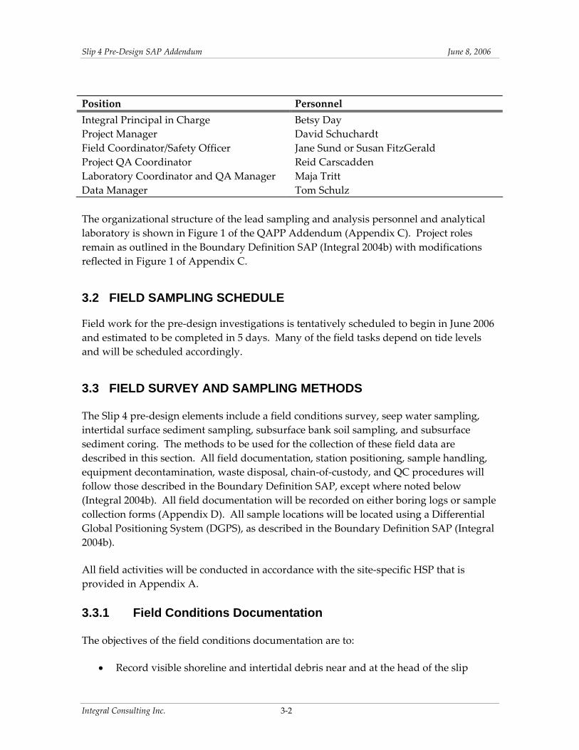
Slip 4 Pre‐Design SAP Addendum June 8 2006
(Appendix D) Photographs will be taken of each sampling interval in the subsurface samples as well as from the individual sampling pits
3331 Surface Sediment Sampling
The surface sediment samples (0ndash10 cm) will be collected during low tide from intertidal Stations SG30 through SG33 using stainless‐steel bowls and spoons The surface sediment will be submitted for PCB and TOC analyses
3332 Subsurface Sediment and Soil Sampling
All subsurface soil samples will be characterized according to the USCS The Visual Manual Method (ASTM D2488) will be used in the field and will be recorded on boring logs except where undisturbed samples for geotechnical characterization are submitted to the laboratory For those samples the laboratory will perform the USCS classification following ASTM D2487 Samples will be handled and shipped as described in Section 334
Samples for Removal Area Characterization
Subsurface sediment cores for the dredge area characterization will be collected using Shelby tube samplers advanced through HSA borings from a barge‐mounted drill rig The proposed borehole locations are shown in Figure 2‐2 Samples will be collected from 0 to 5 ft bml at each location according to the SOP for HSAShelby tube sampling (SOP 6 Appendix B) The core intervals will be sampled discretely or composited per the requirements at each station The cores will be subsampled according to two to three different schemes as discussed below
Sediment cores from seven locations will be used to characterize sediment in the area to be dredged The cores will be subsampled into three sample intervals as described in Section 2 These discrete samples will be analyzed for geotechnical parameters as follows
bull Nine subsamples from SC12 SC13 and SC16 will be analyzed for grain‐size distribution water content specific gravity and Atterberg limits
Six samples will be submitted for chemical analysis to evaluate disposal requirements as follows
bull One composite sample representing the entire recovered lengths of cores from SC12 SC13 and SC16 will be submitted for chemical analysis to evaluate whether the material will require disposal as a Washington State Dangerous Waste Analysis of this sample will include PCBs chlorinated pesticides SVOCs metals
Integral Consulting Inc 3‐5
Slip 4 Pre‐Design SAP Addendum June 8 2006
TPH‐Dx TPH‐G TOC and TCLP analysis for SVOCs chlorinated pesticides and metals
bull Five samples each representing the entire recovered lengths of one of five discrete cores from Stations SC14 through SC18 near the head of the slip will be submitted for PCB analysis to determine if segregation of an area potentially requiring disposal under TSCA regulations is practicable
Bank material in the removal areas will be sampled and submitted for chemical analysis to evaluate whether the material will require disposal as a Washington State Dangerous Waste These bank samples will be collected from hand augers andor hand‐dug test pits advanced to approximately 3ndash4 ft bgs
bull One composite sample will be collected from SB21 representing the approximate 0ndash4 ft depth interval to be removed
bull One composite sample will be collected of material from SB22 and SB23 representing the approximate 0ndash4 ft depth interval to be removed
Chemical analysis of these bank samples will include PCBs chlorinated pesticides SVOCs metals TPH‐Dx TPH‐G TOC and TCLP analysis for SVOCs chlorinated pesticides and metals Geotechnical analyses for these samples will include grain‐size distribution water content Atterberg limits and TOC Due to the widespread occurrence of riprap andor buried debris it is anticipated that hand‐dug test pits (advanced using a shovel) will likely be necessary and locations may need to be adjusted in the field The cores or test pits will be logged and classified following ASTM D2488 The test pits will be logged from the excavated test pit sidewall
Cap Geotechnical Characterization
Subsurface sediment cores for capping geotechnical characterization will be collected using Shelby tubes and split‐spoon samplers advanced through HSAs following the SOP for Shelby Tube Sampling (SOP 6 Appendix B) The samples will consist of undisturbed Shelby tubes collected from the intervals described in Section 2 at Stations SC19 SC20 SC21 and SC22 The undisturbed Shelby tubes will be sealed and submitted to the analytical lab and up to two sample intervals from each boring will be analyzed for consolidation testing The sample intervals for lab testing will be determined by the Integral Field Coordinator at the lab Fine‐grained sediment subsamples will be analyzed by consolidation testing and UU triaxial shear grain‐size distribution water content bulk density specific gravity Atterberg limits and TOC The lab will also record the USCS classification of the undisturbed samples
Integral Consulting Inc 3‐6
Slip 4 Pre‐Design SAP Addendum June 8 2006
The deeper sample intervals from these borings (to 20 ft bml) will be continuously sampled using a split‐spoon sampler logged in the field per USCS and SPT blowcounts will be recorded
Archived Samples
Three archived samples from SC01 collected in 2004 will be analyzed for grain‐size distribution USCS classification water content and Atterberg limits
334 Sample Handling and Transport
Sample jars coolers and packaging material will be supplied by the analytical laboratory Details on the numbers and type of sample containers are provided in the QAPP Addendum (Appendix C) Seep water samples bank subsurface soil samples surface sediment samples and disturbed subsurface sediment samples will be handled and transported in accordance with the procedures in the Boundary Definition SAP (Integral 2004b)
Undisturbed Shelby tube samples will be handled following ASTM D3213 Standard Practice for Handling Storing and Preparing Soft Undisturbed Marine Soil This standard covers the methods for projectcruise reporting and handling transporting and storing soft cohesive undisturbed marine soil The tube ends of the undisturbed Shelby tube samples will be sealed in the field as per SOP 6 (see Appendix B) to prevent leakage of pore water The tubes will be maintained in a vertical orientation and transported to the laboratory with minimal disturbance
335 Equipment Decontamination
The handcores will be rinsed with site water and washed with Liqui‐noxTM detergent prior to use and between sampling stations Decontamination of stainless‐steel bowls and spoons will also be performed before using sampling equipment at each station using the following process
bull Rinse with site water bull Wash with Liqui‐noxTM bull Double rinse with distilled water bull Rinse with deionized water bull Rinse with methanol bull Final rinse with deionized water
If a residual petroleum sheen remains on the sampling equipment or is difficult to remove using the standard decontaminations procedures above a final hexane rinse may be added
Integral Consulting Inc 3‐7
Slip 4 Pre‐Design SAP Addendum June 8 2006
Sample equipment will be kept wrapped in aluminum foil until time for use To minimize sample cross‐contamination disposable gloves will be replaced between stations
336 Investigation-Derived Waste
Investigation‐derived waste will be managed as described in the Boundary Definition SAP (Integral 2004b)
34 FIELD QUALITY CONTROL SAMPLES
QC requirements will be instituted during field sampling laboratory analysis and data management to ensure that the data quality objectives from Integral (2004b) are met Detailed information on QAQC procedures limits and reporting are described in detail in the QAPP (Integral 2004b) and QAPP Addendum (Appendix C)
Field QC samples will be collected as specified in the Boundary Definition SAP (Integral 2004b) with the exception that field replicates will only be collected during seep sampling Field QC samples will include field split samples (for surface sediment sampling) and equipment rinsate blanks (for seep sampling and surface sediment sampling) The types and numbers of QC samples that will be collected are listed in Table 4 of the QAPP Addendum (Appendix C)
35 LABORATORY ANALYSES
Laboratory analyses will be performed according to the Boundary Definition QAPP (Integral 2004b) and the QAPP Addendum (Appendix C)
Integral Consulting Inc 3‐8
Slip 4 Pre‐Design SAP Addendum June 8 2006
4 DATA MANAGEMENT AND REPORTING
During field laboratory and data evaluation operations effective data management is the key to providing consistent accurate and defensible data and data products The management and reporting of field and laboratory data will generally follow the procedures outlined by Integral (2004b) Changes or additions to those procedures based on the specific requirements of this FSP are discussed in the following sections
41 SAMPLE NUMBERING
According to Integral (2004b) all samples will be assigned a unique identification code based on a sample designation scheme designed to suit the needs of the field personnel data management and data users Sample identifiers will consist of two components separated by dashes The first component is SL4 to identify the data as originating in Slip 4 The second part will contain the following abbreviations for the sample type followed by the sample number
SB = subsurface bank soil composite sample CC = subsurface sediment core composite sample SC = subsurface core sample SG = surface grab sample SP = seep water sample
All station IDs will be numbered sequentially Surface and subsurface stations will continue the numbering scheme begun during the 2004 sampling (Integral 2004a) Composite core samples and seep samples will each be numbered sequentially starting with 01
Subsurface core samples will also have a letter that is placed after the sample number to designate the sample horizon in the core ldquoArdquo will be used to indicate the top interval (ie 0‐ to 2‐ft horizon) All subsequent (deeper) sample intervals will be indicated in alphabetical order (ldquoBrdquo 2ndash4 ft ldquoCrdquo 4ndash5 ft) Core samples collected from the full length of the core will be indicated by ldquoXrdquo
Seep water samples and composite core samples will be numbered sequentially
Some examples of sample labels include
bull SL4‐SB02 Second composite subsurface bank soil sample the stations comprising this composite will be noted in the field log book
Integral Consulting Inc 4‐1
Slip 4 Pre‐Design SAP Addendum June 8 2006
bull SL4‐CC01 First composite sediment core sample the core stations comprising this composite will be noted in the field log book
bull SL4‐SC14C Core sample from the 4‐ to 5‐ft horizon at Station 14
bull SL4‐SC15X Sample representing the full length of the core collected at Station 15
bull SL4‐SG32 Surface grab sample from intertidal Station 32
bull SL4‐SP01 First seep water sample station
42 LABORATORY DATA
Laboratory data reporting procedures will follow those of the Boundary Definition SAP (Integral 2004b)
43 DATA MANAGEMENT
Data management procedures will follow those of the Boundary Definition SAP Integral will continue to use the Environmental Quality Information System (EQuIS) in conjunction with the ArcView 9 geographic information system (GIS) tools to manage summarize and report the generated data Pre‐design data will be submitted electronically to EPA in the SEDQUAL format
44 DATA REVIEW AND REPORTING SCHEDULE
Data validation procedures will follow those called for in the Boundary Definition SAP (Integral 2004b) The results of this pre‐design investigation sampling will be presented in a Pre‐Design Sampling Data Report that will be an appendix to the 60 Design Documents for the Slip 4 Early Action currently scheduled for fall 2006 Information to be included in the Data Report will include but is not limited to
bull Field methods and any deviations from the SAP bull Field change requests bull Actual sample locations bull Laboratory analysis results bull Data validation reports bull Core logs bull Sample description forms bull Photodocumentation bull Description of geophysical features on Zone 5 embankment bull Location of the East Marginal Way PS EOF outfall
Integral Consulting Inc 4‐2
Slip 4 Pre‐Design SAP Addendum June 8 2006
bull Summary of under‐pier sediment accumulations in riprap interstices bull Engineerrsquos estimate of debris types and quantities
Integral Consulting Inc 4‐3
Slip 4 Pre‐Design SAP Addendum June 8 2006
This page intentionally left blank
Integral Consulting Inc 4‐4
Slip 4 Pre‐Design SAP Addendum June 8 2006
5 REFERENCES
ASTM 2003 Annual Book of ASTM Standards Volume 0408 American Society for Testing and Materials Philadelphia PA
DRCC 2006 Comment Letter Re Draft Lower Duwamish Waterway Slip 4 Early Action Area EECA January 6 2006 Duwamish River Cleanup Coalition Seattle WA
Ecology 2003 Sediment Sampling and Analysis Appendix Guidance on Development of Sediment Sampling and Analysis Plans Meeting the Requirements of the Sediment Management Standards PTI Environmental Services Bellevue WA and Washington Department of Ecology Olympia WA
Ecology 2005 Memorandum Re Slip 4 Upland Soil and Sediment PCB Investigation August 22 2005 Prepared by Sunny Becker Washington Department of Ecology Olympia WA
Integral 2004a Lower Duwamish Waterway Slip 4 Early Action Area Cruise and Data Report Prepared for City of Seattle and King County WA Integral Consulting Inc Mercer Island WA
Integral 2004b Lower Duwamish Waterway Slip 4 Early Action Area Sampling and Analysis Plan for Boundary Definition Prepared for City of Seattle and King County WA Integral Consulting Inc Mercer Island WA
Integral 2006 Lower Duwamish Waterway Slip 4 Early Action Area Engineering EvaluationCost Analysis Prepared for City of Seattle and King County WA Integral Consulting Inc Mercer Island WA
Landau 1990 Environmental Site Assessment First Interstate Bank of Washington Property 7400 8th Ave S amp 7343 E Marginal Way S Prepared for The Boeing Company Seattle WA Landau Associates Inc Edmonds WA
Schmoyer B 2006 Personal Communication (email of January 23 2006 to V Fagerness Integral Consulting Inc Olympia WA regarding modifications to outfall names) Seattle Public Utilities Seattle WA
SEA 2004 Lower Duwamish Waterway Slip 4 Early Action Area Summary of Existing Information and Identification of Data Gaps Prepared for City of Seattle and King County WA Striplin Environmental Associates Olympia WA
Integral Consulting Inc 5‐1
Slip 4 Pre‐Design SAP Addendum June 8 2006
USEPA 1988 Guidance for Conducting Remedial Investigations and Feasibility Studies under CERCLA Interim Final OWSER Directive 93553‐01 EPA 540‐G‐89‐004 US Environmental Protection Agency Office of Emergency and Remedial Response Washington DC
USEPA 1998 Assessment and Remediation of Contaminated Sediments (ARCS) Program Guidance for In‐Situ Subaqueous Capping of Contaminated Sediments EPA 905‐B96‐004 Prepared by US Army Corps of Engineers (Michael Palermo Jan Miller) and Danny D Reible Louisiana State University Great Lakes National Program Office Chicago IL
USEPA 2002 Guidance on Quality Assurance Project Plans EPA QAG‐5 EPA240R‐02009 US Environmental Protection Agency Office of Environmental Information Washington DC
USEPA 2006 Action Memorandum for Non‐Time Critical Removal Action at the Slip 4 Early Action Area of the Lower Duwamish Waterway Superfund Site Seattle Washington dated May 3 2006 US Environmental Protection Agency Region 10 Seattle WA
Windward 2004a Quality Assurance Project Plan Survey and Sampling of Lower Duwamish Waterway Seeps Prepared for Lower Duwamish Waterway Group for submittal to US Environmental Protection Agency and Washington State Department of Ecology Windward Environmental LLC Seattle WA
Windward 2004b Data Report Survey and Sampling of Lower Duwamish Waterway Seeps Prepared for Lower Duwamish Waterway Group for submittal to US Environmental Protection Agency and Washington State Department of Ecology Windward Environmental LLC Seattle WA
Integral Consulting Inc 5‐2
FIGURES
4 5
Slip 4
ChannelSlip 4 Channel
East Marginal
MapD
ocum
ent(
OP
rojec
tsDu
wami
sh_O
LYP
rojec
tsSli
p4_E
ECAS
iteLo
catio
nMap
mxd
) 52
4200
6--1
0141
1AM
Seattle Elliott Bay
Spokane St Bridge
Duwamish Waterway
RM 1
1st Ave S Bridge
RM 3 Slip 4
16th Ave S Bridge
Burien
RM 5
Turning Basin No 3
E Marginal Way Bridge
Tukwila
Figure 1-1Site Location Map
Slip 4 Pre-design SAP Map Feature Sources King County GIS Seattle Public Utilities USACE Ecology and others
18
14
16
12
16
12
12
14
AV
S
8TH
AV
S
Duwamish Waterway
Slip 4
8
14
12
1 0
16
2 0 222 4 2 6
28
3 0
32
20
8
1 4
10
1 2
1 8
24
18
16
2 2
16
14
1 4
1 4
12
1 6
1 8
14
18
14
1 4
10
1 6
1 6
1 8
1 2
1 6
16
1 8
1 8
1 8
8 TH
S OTHELLO ST NP RR
E MARGINAL WY S
Map
Doc
umen
t (O
Pro
ject
sD
uwam
ish_
OLY
Pro
ject
sSl
ip4_
EEC
AFi
gure
_2-5
_Hab
itat_
size
-AP
mxd
)4
112
006
--4
193
8 P
M
0 50 100 150 200 Feet deg NAD83
Slip 4 area Habitat Typesbeach
vegetation
DataQueryArea
Paved edgeBuildings
Bulkhead
shallow subtidal
berths amp docks wriprap
Dredging Areas - Post-1990
riprapmudflat
Figure 2-1 Site Features
Slip 4 Pre-design SAP Map Feature Sources King County GIS Seattle Public Utilities USACE Ecology and others
TABLES
Slip 4 Pre‐Design SAP Addendum June 8 2006
Table 2-1 Slip 4 Data Needs for Pre-Design Investigations Chemical Analyses Geotechnical Analyses
Purpose Matrix Sample Type Sampling Frequency Stations Analytes Samples Laboratory Field4 Samples Notes
Field Conditions Documentation
-- -- -- -- -- -- -- -- -- Debris tally photodocument locate EOF assess under-pier sediment presence document Zone 5 characteristics Structural survey of pier and Zone 4 bulkhead (at later date)
Seep Water Sampling (Bank)
Water Intertidal seep grab1 Estimated 4ndash6 locations field-determined
SP01 through SP06 PCBs DOC 4-6 -- -- NA Filtered samples Collect at low tide per LDW procedures Field WQ parameters measured prior to sampling 1
Intertidal Surface Sediments Verify Intertidal Boundary at Boeing Riprap
Sediment Intertidal surface grab (0-10 cm from spoonbowl)
4 locations south of boundary above 0 ft MLLW
SG30 SG31 SG32 SG33
PCBs TOC 4 -- -- 0 Requested by EPA
Intertidal and Subtidal Subsurface Sediments Sediment Disposal Characterization - TSCA Remediation Waste
Sediment Intertidal HSAShelby tubes 5 ft deep
5 locations near SL4-6A one full-depth composite sample per core
Sediment Disposal Characterization -Washington State Dangeous Waste Dredgeability and Handling
Sediment Intertidal HSAShelby tubes 5 ft deep
3 locations in dredge area including one at SL4-6A Index properties on individual core segments Disposal characterization on one composited sample of all three 5-ft cores
Dredgeability and Handling Sediment Archived cores Archived sediment sample SC-01 0ndash2ft 2ndash4ft 4ndash6 ft
Cap Design - Geotechnical Characterization of Underlying Sediments
Sediment HSA to 20 ft bml 0-25 ft 25-5 ft 5-75 ft Shelby tubes Split spoons to 20 ft
4 locations in cap area From each location analyze one or two representative 6-in intervals of fine-grained material for consolidation and strength Analyze one or two additional intervals for index properties Sampling intervals to be determined in field based on stratigraphy of the sample
SC14 SC15 SC16 SC17 SC18
PCBs 5 -- USCS classification 03 To assess need for segregation of TSCA material gt50 mgkg PCB
SC12 SC13 SC16 On Composite SVOCs inorganics chlorinated pesticides PCBs TOC TPH-G TPH-Dx TCLP (SVOCs inorganics pesticides) 6
1 On individual sample intervals2 water content specific gravity grain size Atterberg limits TOC
USCS classification 9
SC01 (archived) -- -- USCS classification5
water content specific gravity grain size Atterberg limits TOC
-- 3
SC19 SC20 SC21 SC22
-- -- On Shelby tubes Consolidation and UU Triaxial Shear (only fine-grained materials will be analyzed for these parameters) For the following analyses representative subsamples will be analyzed regardless of material type USCS classification5 water content bulk density specific gravity grain size Atterberg limits TOC
On Split Spoons USCS classification
8 Borings to 20 ft bml with both SPT and Shelby sampling Engineer to direct SPTShelby sampling Submit capped Shelby tubes to lab for subsampling Archive representative split spoon samples Up to 2 consolidation and triaxial samples may be submitted per boring on silt or clay units
Integral Consulting Inc 1 of 2
Slip 4 Pre‐Design SAP Addendum June 8 2006
Table 2-1 Slip 4 Data Needs for Pre-Design Investigations Chemical Analyses Geotechnical Analyses
Purpose Matrix Sample Type Sampling Frequency Stations Analytes Samples Laboratory Field4 Samples Notes
Bank Subsurface Soils
Zone 2 Bank ExcavationDisposal Characterization
Bank soils Composite soil sample from hand auger boring or hand-dug test pit
One composite sample from a boring (to 3ndash4 bgs) in Zone 2
SB21 SVOCs inorganics chlorinated pesticides PCBs TOC TPH-G TPH-Dx TCLP (SVOCs inorganics pesticides) 6
1 Water content specific gravity grain size Atterberg limits
USCS classification 1
Zone 3 4 5 Bank Excavation Disposal Characterization
Bank soils Composite soil sample from hand auger borings or hand-dug test pits
One composite sample from borings (to 3ndash4 bgs) in Zone 3 4 and 5
SB22 SB23 SVOCs inorganics chlorinated pesticides PCBs TOC TPH-G TPH-Dx TCLP (SVOCs inorganics pesticides)6
1 Water content specific gravity grain size Atterberg limits
USCS classification 1
Notes surface 1 Field water quality parameters will be measured before sampling at each seep location and in adjacent surface water Parameters include temperature conductivity turbidity dissolved oxygen pH salinity and oxidation-reduction potential 2 Sample target intervals will be from 0ndash2 ft below mudline (bml) 2ndash4 ft bml and 4ndash5 ft bml 3 Geotechnical analyses on samples from SC16 are included under Sediment disposal characterization - Washington State Dangerous Waste 4 USCS classification will be conducted in the field following ASTM D2488 Visual Manual Procedure 5 USCS classification will be conducted by the laboratory following ASTM D2487 6 TCLP aliquots to be archived for potential future analysis -- - not applicable
Integral Consulting Inc 2 of 2
Slip 4 Pre‐Design SAP Addendum June 8 2006
Table 2-2 Slip 4 Proposed Sample Locations for Pre-Design Investigations
Station ID Northing Easting
SC12 1992785071 1273514482 SC13 1993604344 1273429089 SC14 1994268725 1273459595 SC15 1994252542 1273498824 SC16 1994490406 1273482094 SC17 1994657131 1273501524 SC18 199465893 1273468952 SC19 1988678836 1273370448 SC20 1990483314 1273510154 SC21 1992283014 127340771 SC22 1993978931 1273521878 SB21 1994112452 1273410305 SB22 1992791657 1273582561 SB23 1988407995 1273394217 SG30 1988051522 1273345121 SG31 198791841 1273358284 SG32 1987818575 1273352892 SG33 1987902563 1273335606
Notes Horizontal Datum Washington State Plane Coordinate System North Zone (NAD 8391) US feet
Integral Consulting Inc 1
APPENDIX B
STANDARD
OPERATING
PROCEDURES
SOP‐6 Revision 52006
STANDARD OPERATING PROCEDURE 6
Hollow-Stem Auger DrillingSediment Sampling
Scope and Application
Soilsediment cores are collected to evaluate sediment at depths that greatly exceed those achieved by grab or other surface samplers The purpose of this standard operating procedure (SOP) is to define and standardize procedures for core collection using split‐spoon and Shelby tube samplers advanced through hollow‐stem auger borings following American Society for Testing and Materials (ASTM) Method D1586 and Method D1587 respectively The use of Shelby tube samplers or split‐spoon samplers is specified in the Slip 4 Pre‐Design Sampling and Analysis Plan Addendum (Integral 2006) Shelby tubes will be used to recover relatively undisturbed soil samples suitable for laboratory tests of engineering properties such as strength compressibility permeability and density
Required Equipment
bull Sampling and Analysis Plan (SAP)
bull Health and Safety Plan (HSP)
bull Site logbook and boring log
bull Indelible black‐ink pens and markers
bull Camera
bull Hollow‐stem auger drill rig
bull Driller and helper
bull Split‐spoon samplers (typically 2‐in diameter a larger 3‐in diameter 2‐ft‐length split‐spoon may be used to obtain more material from each depth interval)
bull Shelby tube samplers conforming to thin‐walled tube specifications outlined in ASTM D1587 with a 2‐ to 5‐in OD and 5 to 10 times the diameter in length Wax and end caps will also be provided for proper field sealing
bull Photoionization detector (PID)
bull Plastic sheeting
bull 55‐gallon drums (if required)
bull Insulated cooler(s) chain‐of‐custody seals Ziplocreg bags
bull Sample labels and appropriate documentation
Integral Consulting Inc 1
SOP‐6 Revision 52006
bull Assorted geology supplies (eg hand lens grain‐size card scales etc)
bull Decontamination equipment (SOP‐10)
Typical Procedures
1 Ensure underground utilities in vicinity of each boring location have been marked prior to mobilizing drill rig to site
2 Conduct daily site activityhealth and safety briefing
3 Calibrate field instrumentation if applicable
4 Record necessary data in field logbook
5 Obtain photograph(s) of site before drilling
6 Place plastic sheeting andor drums at drilling location to collect cuttings (if necessary)
7 Move equipment and supplies to drilling location
8 Set up decontamination and sampling stations
Split-Spoon Sampling
1 Obtain surface soil samples if required
2 Drill to first sampling depth as described in the SAP
3 Place decontaminated split‐spoon sampler on center rods
4 Drive split‐spoon sampler as described in ASTM Method D‐1586 Drive sampler to 18 inch or to refusal (no progress for 50 blows) Record blow counts on boring log form Retrieve sampler
5 Screen sampler with PID (if required)
6 Describe soil in accordance with ASTM D2488 on the boring log form
7 Composite soil sample as necessary If volatile organic compound (VOC) samples are to be collected collect VOC sample prior to describing soil
8 Continue drilling at next sample location Collect samples as outlined above
9 Label and manage sample containers in accordance with the site‐specific SAP section for shipping and handling of samples
10 Decontaminate sampling equipment in accordance with the site‐specific SAP
11 Document activities in site logbook
12 Backfill or grout borehole as required
Integral Consulting Inc 2
SOP‐6 Revision 52006
13 Move to next location
Shelby Tube Sampling
1 Obtain surface soil samples if required
2 Drill to first sampling depth as described in the SAP
3 Place decontaminated Shelby tube sampler on center rods
4 Drive Shelby tube sampler as described in ASTM Method D1587 Retrieve the sampling tube and remove the disturbed material from the top of the tube In addition remove 1 inch of soil from the base of the tube Place an impervious disk at both ends of the tube seal with a wax plug prior to shipment to the laboratory
5 If Shelby tubes are to be extruded in the field for composite sampling the driller will use a hydraulic extruder to obtain the sample The core is then described in accordance with ASTM Method D2488 on the boring log form Samples will then be composited as necessary for analysis
6 Screen sampler with PID (if required)
7 Label and manage sample containers in accordance with the site‐specific SAP section for shipping and handling of samples The sample tube should be packed in StyrofoamTM plugs or other cushioning material to prevent disturbance of the sample
8 Continue drilling to next sample location Collect samples as outlined above
9 Decontaminate sampling equipment in accordance with the site‐specific SAP section
10 Document activities in site logbook
11 Backfill or grout borehole as required
12 Move to next location
Reference
Integral 2006 Lower Duwamish Waterway Slip 4 Early Action Area Sampling and Analysis Plan for Boundary Definition Addendum Pre‐Design Investigation Sampling Prepared for Seattle City Light and King County Seattle WA Integral Consulting Inc Mercer Island WA
Integral Consulting Inc 3
APPENDIX C
QAPP ADDENDUM
LOWER DUWAMISH WATERWAY
SLIP 4 EARLY ACTION AREA
Quality Assurance Project Plan for Boundary Definition
Addendum Pre‐Design Investigation Sampling
Submitted to US Environmental Protection Agency Region 10
1200 Sixth Avenue Seattle WA 98101
Submitted by City of Seattle King County
Prepared by
7900 SE 28th Street Suite 300 Mercer Island WA 98040
June 8 2006
Pre‐Design QAPP Addendum June 8 2006
A PROJECT MANAGEMENT
A1 TITLE AND APPROVAL SHEET
QUALITY ASSURANCE PROJECT PLAN FOR BOUNDARY DEFINITION
PRE‐DESIGN INVESTIGATION SAMPLING ADDENDUM
LOWER DUWAMISH WATERWAY SLIP 4 EARLY ACTION AREA
SEATTLE WASHINGTON
Quality Assurance Project Plan Approvals
EPA Project Coordinator Karen Keeley Date
EPA QA Manager Ginna Grepo‐Grove Date
City of Seattle Project Manager Jennie Goldberg Date
Integral Principal in Charge Betsy Day Date
Integral Project Manager David Schuchardt Date
Integral Project QA Coordinator Reid Carscadden Date
ARI Project Manager Sue Dunnihoo Date
ARI QA Manager Dave Mitchell Date
Integral Consulting Inc ii
Pre‐Design QAPP Addendum June 8 2006
This page intentionally left blank
Integral Consulting Inc iii
Pre‐Design QAPP Addendum June 8 2006
A2 TABLE OF CONTENTS
A PROJECT MANAGEMENT ii A1 TITLE AND APPROVAL SHEET ii A2 TABLE OF CONTENTS iv A3 DISTRIBUTION LIST vii A4 INTRODUCTION AND PROJECT AND TASK ORGANIZATION1
A41 Introduction1 A42 Project and Task Organization1
A5 PROBLEM DEFINITION AND BACKGROUND1 A6 TASK DESCRIPTION 2 A7 QUALITY OBJECTIVES AND CRITERIA FOR MEASUREMENT DATA3
SECTION B DATA GENERATION AND ACQUISITION5 B1 SAMPLING PROCESS DESIGN 5 B2 SAMPLING METHODS7 B3 SAMPLE HANDLING AND CUSTODY7 B4 ANALYTICAL METHODS7 B5 QUALITY CONTROL 7
B51 Field Quality Control Samples 7
REFERENCES9
Integral Consulting Inc iv
Pre‐Design QAPP Addendum June 8 2006
LIST OF FIGURES Figure A4‐1 Organization Chart
LIST OF TABLES Table A4‐1 Project Team Contact Information Table A6‐1 Estimated Numbers of Pre‐Design Samples by Sample Type Table A6‐2 Target Analytes Methods and Method Reporting Limits for Pre‐Design
Investigation Samples Table A7‐1 Measurement Quality Objectives Table B2‐1 Sample Containers Preservation Holding Times and Sample Volume
Integral Consulting Inc v
Pre‐Design QAPP Addendum June 8 2006
ACRONYMS AND ABBREVIATIONS ARI Analytical Resources Inc ASTM American Society for Testing and Materials bml below the mudline DOC dissolved organic carbon DQOs data quality objectives EDD electronic data deliverables EECA engineering evaluationcost analysis EPA US Environmental Protection Agency EQuIS Environmental Quality Information System LDW Lower Duwamish Waterway MDLs method detection limits MQOs measurement quality objectives MRLs method reporting limits MS mass spectrometry PCB polychlorinated biphenyl PSEP Puget Sound Estuary Program QAPP quality assurance project plan QC quality control SAP sampling and analysis plan SVOCs semivolatile organic compounds TCLP Toxicity Characteristic Leaching Procedure TOC total organic carbon TPH total petroleum hydrocarbon TPH‐Dx extended diesel‐range total petroleum hydrocarbon TPH‐G gasoline‐range total petroleum hydrocarbon TSCA Toxic Substances Control Act USCS Unified Soil Classification System
Integral Consulting Inc vi
Pre‐Design QAPP Addendum June 8 2006
A3 DISTRIBUTION LIST
US EPA Region 10 Remedial Project Manager Karen Keeley
US EPA QA Manager Ginna Grepo‐Grove
City of Seattle Project Coordinator Jennie Goldberg
Integral Principal in Charge Betsy Day
Integral Project Manager David Schuchardt Integral Project QA Coordinator Reid Carscadden
Integral Field Coordinator Jane Sund or Susan FitzGerald
Integral Laboratory Coordinator amp QA Manager Maja Tritt Integral Data Manager Tom Schulz
ARI Project Manager Sue Dunnihoo
ARI QA Manager Dave Mitchell
Integral Consulting Inc vii
Pre‐Design QAPP Addendum June 8 2006
A4 INTRODUCTION AND PROJECT AND TASK ORGANIZATION
A41 Introduction
This quality assurance project plan (QAPP) addendum describes procedures that will be used to complete a pre‐design investigation to characterize seep water sediment and bank soil in the Slip 4 Early Action Area of the Lower Duwamish Waterway (LDW) This addendum supplements the Boundary Definition QAPP (Integral 2004a) The Boundary Definition QAPP describes procedures and requirements for the generation of data of documented acceptable quality that will be used for the pre‐design investigation This Pre‐Design QAPP Addendum addresses procedures that will be used for the pre‐design investigation that are not described in the Boundary Definition QAPP
Supplemental information to Sections A and B of the Boundary Definition QAPP is provided in this Pre‐Design QAPP Addendum Special training and certification and documents and records are described in Sections A8 and A9 respectively of the Boundary Definition QAPP and are not addressed further in this QAPP addendum
Procedures for project assessment and oversight will be completed as described in Section C of the Boundary Definition QAPP
All data for organic inorganic and conventional analytes including total solids used for dry‐weight conversions will be verified and validated Data for geotechnical characteristics do not require validation because of the mechanical nature of these tests Data verification and validation and data quality assessment procedures will be completed as described in Section D of the Boundary Definition QAPP
A42 PROJECT AND TASK ORGANIZATION
The organizational structure for this project is illustrated in Figure A4‐1 Contact information related to the pre‐design investigation is provided in Table A4‐1 of this QAPP addendum Project and quality assurance responsibilities are described in detail in Section 31 of the Boundary Definition sampling and analysis plan (SAP) and Pre‐Design SAP Addendum (Integral 2004b and 2006b respectively)
A5 PROBLEM DEFINITION AND BACKGROUND
The primary objective of this Slip 4 pre‐design investigation is to fill identified data gaps to support the design of the removal action alternative recommended by the City of Seattle and King County as presented in the engineering evaluationcost analysis (EECA) (Integral 2006a) Data will be collected to support the following activities
Integral Consulting Inc 1
Pre‐Design QAPP Addendum June 8 2006
bull Verification of the removal boundary bull Characterization of seep water bull Dredging evaluation of the removal area bull Characterization of removal area sediment and bank soil for disposal bull Geotechnical characterization of the capping area
Sampling activities will include collection of seep samples surface and subsurface sediment samples and subsurface bank samples Details are provided in Sections 21 and 22 of the Pre‐Design SAP Addendum
A6 TASK DESCRIPTION
The tasks to be completed for this project include fieldwork laboratory analyses data quality evaluation data management data analysis and report preparation The Slip 4 pre‐design elements include a field conditions survey seep water sampling intertidal surface sediment sampling subsurface bank soil sampling and subsurface sediment coring The methods to be used for the collection of these samples are described in Section 33 of the Pre‐Design SAP Addendum All field documentation station positioning sample handling equipment decontamination waste disposal chain‐of‐custody and quality control procedures will follow those described in the Boundary Definition SAP (Integral 2004b) except where noted in the Pre‐Design SAP Addendum
Integral will collect the various sediment bank soil and seep water samples and prepare samples for delivery to the laboratory Susan FitzGerald or Jane Sund of Integral will serve as field coordinator and will assume custody of cores and samples as they are collected A list of samples and analyses is provided in Table A6‐1 Sample locations are provided in Figure 2‐2 of the Pre‐Design SAP Addendum (Integral 2006b)
Samples will undergo chemical and geotechnical testing by Analytical Resources Inc (ARI Seattle WA) for analytes listed in Table A6‐2 Analyses will be completed using US Environmental Protection Agency (EPA) American Society for Testing and Materials (ASTM) and Puget Sound Estuary Program (PSEP) methods (USEPA 2003 PSEP 1986 1997ab ASTM 2003) as indicated in Table A6‐2 Full laboratory data reports will be provided in hardcopy and electronic data deliverables (EDDs) will be provided in spreadsheet format as required for importing into the database The Environmental Quality Information System (EQuIS) database application will be used to manage the field and laboratory data Data will also be submitted electronically to EPA in SEDQUAL format
Data verification will be completed by Integral for data generated in the field and by ARI for data generated at the laboratory The accuracy and completeness of the final database will be verified by Integral Data validation and data quality assessment will be
Integral Consulting Inc 2
Pre‐Design QAPP Addendum June 8 2006
completed by an independent validation firm which will be selected at a later date The validation firm will also complete data verification (ie verifying that analytical procedures and calculations were completed correctly and checking transcriptions of the laboratory data) for the first data package for each analysis as part of the full validation that will be completed for these packages
The results of the Pre‐Design SAP Addendum field sampling will be presented in the 60 Design Documents for the Slip 4 Early Action currently scheduled for completion in fall 2006
The start date for field sampling will be determined following EPA approval of the project SAP and QAPP addenda and pending property access permission from property owners Currently it is anticipated that field sampling will begin in June 2006 The field and reporting schedules are discussed further in Sections 32 and 44 respectively of the Pre‐Design SAP Addendum
A7 QUALITY OBJECTIVES AND CRITERIA FOR MEASUREMENT DATA
Data quality objectives (DQOs) for the pre‐design investigation are described in Section A7 of the Boundary Definition QAPP Target method reporting limits (MRLs) and method detection limits (MDLs) for this project are summarized in Table A6‐2 Measurement quality objectives (MQOs) for this project are summarized in Table A7‐1 Analyte concentrations for this project will be reported to the MDL as described in the Boundary Definition QAPP
Integral Consulting Inc 3
Pre‐Design QAPP Addendum June 8 2006
This page intentionally left blank
Integral Consulting Inc 4
Pre‐Design QAPP Addendum June 8 2006
SECTION B DATA GENERATION AND ACQUISITION
B1 SAMPLING PROCESS DESIGN
This section supplements Section B1 of the Boundary Definition QAPP The sampling effort for this study will include the collection of seep water surface sediment subsurface sediment and subsurface bank soil from Slip 4 in the LDW
Seep water will be collected as discrete samples from individual seep locations (to be determined in the field) Water quality parameters (conductivity turbidity temperature dissolved oxygen pH salinity and oxidation‐reduction potential) will be measured in the field at each seep and in adjacent surface water prior to sample collection Seep samples will be filtered in the field through 10‐μm glass filters and submitted for laboratory analysis for polychlorinated biphenyl (PCB) Aroclors and dissolved organic carbon (DOC)
Surface sediment samples will be collected from the 0ndash10 cm interval at four locations and will be analyzed for total organic carbon (TOC) and PCB Aroclors
All subsurface soil samples will be characterized according to the Unified Soil Classification System (USCS) as per current annual American Society for Testing and Materials (ASTM) Methods This visualmanual classification will occur in the field per ASTM D2488 and will be recorded on boring logs except where undisturbed samples for geotechnical characterization are submitted to the laboratory For those samples the laboratory will perform the USCS classification following ASTM D2487 Field USCS classification is not considered an ldquoanalysisrdquo in the QAPP
Sediment cores from 0 to 5 ft below the mudline (bml) will be collected from seven locations to characterize sediment in the area to be dredged Chemical analyses will be required on six samples as follows
bull One composite sample representing the entire 0‐ to 5‐ft lengths of cores from three of the locations will be submitted for chemical analysis to evaluate whether the material will require disposal as a Washington State Dangerous Waste Analysis of this sample will include PCB Aroclors chlorinated pesticides semivolatile organic compounds (SVOCs) metals extended diesel‐range total petroleum hydrocarbons (TPH‐Dx) gasoline‐range TPH (TPH‐G) and TOC An additional aliquot of this sample will be archived for potential future Toxicity Characteristic Leaching Procedure (TCLP) analyses for SVOCs chlorinated pesticides and metals
Integral Consulting Inc 5
Pre‐Design QAPP Addendum June 8 2006
bull Five samples representing the 0‐ to 5‐ft lengths of five discrete cores near the head of the slip will be submitted for PCB Aroclor analysis to determine if segregation of an area potentially requiring disposal under the Toxic Substances Control Act (TSCA) regulations is practicable
The cores will also be subsampled into three sample intervals (0ndash2 ft bml 2ndash4 ft bml and 4ndash5 ft bml) These discrete samples will be analyzed for geotechnical parameters as follows
bull Nine subsamples from three cores (SC12 SC13 and SC16) representing the area to be dredged will be analyzed for grain‐size distribution water content specific gravity Atterberg limits and TOC One of the cores in this group (SC16) is located in the potential TSCA area
bull Three archived samples from SC01 (0ndash2 ft 2ndash4 ft and 4ndash6 ft) collected in 2004 will be analyzed for grain‐size distribution water content USCS classification specific gravity Atterberg limits and TOC
Samples of bank soil from bank removal areas are needed to characterize the material for disposal Two composite samples will be collected using hand auger boring or hand dug test pit one sample from Zone 2 and one sample from Zones 3 4 and 5 These samples will be submitted for chemical and geotechnical analyses Chemical analytes will include PCB Aroclors chlorinated pesticides SVOCs metals TPH‐Dx TPH‐G TOC and TCLP analysis for SVOCs chlorinated pesticides and metals Samples collected for TCLP analysis of SVOCs metals and chlorinated pesticides will be archived at the laboratory and analysis will be contingent on the results of dry‐weight analysis TCLP analysis will only need to be performed when the TCLP contaminants in the results from the total analysis are greater than or equal to 20 times the maximum concentration for toxicity characteristic regulatory levels (set forth in Table 1 of 40 CFR 26124) The ldquo20 times rulerdquo is allowable because of the sample dilution that is a component of the TCLP Method 1311 (Section 12 of this method) as is clarified in EPA 540‐R‐94‐005a Geotechnical analyses will include grain‐size distribution water content specific gravity Atterberg limits and TOC
Sediment samples from four cores will be collected for geotechnical analyses to determine the consolidation properties strength and bearing capacity of the underlying sediments These samples will be analyzed by consolidation testing unconsolidated undrained (UU) triaxial shear grain‐size distribution USCS classification water content bulk density specific gravity Atterberg limits and TOC
Field quality control (QC) samples will be collected for chemical analysis as specified in the QAPP (Integral 2004a) with the exception that field duplicate cores will not be
Integral Consulting Inc 6
Pre‐Design QAPP Addendum June 8 2006
collected Field QC samples are described in Section 36 of the Boundary Definition SAP (Integral 2004b) and Section 34 of the Pre‐Design SAP Addendum (Integral 2006b)
B2 SAMPLING METHODS
This section supplements Section B2 of the Boundary Definition QAPP
Seep samples will be collected using either a funnel or peristaltic pump with attached dedicated disposal tubing Intertidal surface sediment will be collected using stainless‐steel bowls and spoons Subsurface sediment cores for dredge area characterization and for geotechnical evaluation will be collected using Shelby tubes and split‐spoon samplers advanced through hollow‐stem augers using a barge‐mounted drill rig Subsurface bank soil samples will be collected using hand augers or hand‐dug test pits Sampling methods are described in Section 33 of the Pre‐Design SAP Addendum Requirements for sample containers storage temperature and holding times for sediment and seep water samples are summarized in Table B2‐1 of this Pre‐Design QAPP Addendum
B3 SAMPLE HANDLING AND CUSTODY
Sample handling and custody procedures will be completed as described in Section 334 of the Pre‐Design SAP Addendum (Integral 2006b)
B4 ANALYTICAL METHODS
Analyses will be completed according to the methods provided in Table A6‐2 These methods will be modified in some cases as described in the Boundary Definition QAPP Sediment samples will be analyzed for SVOCs by full‐scan mass spectrometry (MS) Selected ion monitoring will not be used because the sensitivity of full‐scan MS is sufficient to meet the study objectives
B5 QUALITY CONTROL
Quality control samples will be prepared in the field and at the laboratories to monitor the bias and precision of the sample collection and analysis procedures Field quality control samples are described below Laboratory quality control will be completed as described in the Boundary Definition QAPP
B51 Field Quality Control Samples
Field QC samples for the pre‐design investigation will include field duplicates (for surface sediment sampling) field replicates (for seep sampling) and equipment rinse blanks (for
Integral Consulting Inc 7
Pre‐Design QAPP Addendum June 8 2006
seep and surface sediment sampling) Field QC samples will be collected at a minimum for seep and surface sediment samples at a frequency of 5 percent of the sample total The procedures for preparing field replicates duplicates and rinse blanks are presented in Section 36 of the Boundary Definition SAP (Integral 2004b) and Section 34 of the Pre‐Design SAP Addendum (Integral 2006b) Validation criteria and procedures for field QC samples are described in Sections D1 and D2 of the Boundary Definition QAPP (Integral 2004a)
Integral Consulting Inc 8
Pre‐Design QAPP Addendum June 8 2006
REFERENCES
ASTM 2003 Annual Book of ASTM Standards Volume 0408 American Society for Testing and Materials Philadelphia PA
Integral 2004a Lower Duwamish Waterway Slip 4 Early Action Area Quality Assurance Project Plan for Boundary Definition Prepared for Seattle City Light and King County Seattle WA Integral Consulting Inc Mercer Island WA
Integral 2004b Lower Duwamish Waterway Slip 4 Early Action Area Sampling and Analysis Plan for Boundary Definition Prepared for City of Seattle and King County WA Integral Consulting Inc Mercer Island WA
Integral 2006a Lower Duwamish Waterway Slip 4 Early Action Area Engineering EvaluationCost Analysis Submitted to US EPA Region 10 City of Seattle King County Seattle WA Integral Consulting Inc Mercer Island WA
Integral 2006b Lower Duwamish Waterway Slip 4 Early Action Area Sampling and Analysis Plan for Boundary Definition Addendum Pre‐Design Investigation Sampling Prepared for Seattle City Light and King County Seattle WA Integral Consulting Inc Mercer Island WA
Plumb Jr RH 1981 Procedures for Handling and Chemical Analysis of Sediment and Water Samples Technical Report EPACE‐81‐1 Prepared by Great Lakes Laboratory State University College at Buffalo Buffalo NY for the US Environmental Protection AgencyUS Army Corps of Engineers Technical Committee on Criteria for Dredged and Fill Material Published by the US Army Engineer Waterways Experiment Station CE Vicksburg MS
PSEP 1986 Puget Sound Estuary Program Recommended Protocols for Measuring Conventional Sediment Variables in Puget Sound Final Report TC‐3991‐04 Prepared for US Environmental Protection Agency Region 10 Seattle WA Tetra Tech and HRA Inc Bellevue WA (minor corrections April 2003)
PSEP 1997a Puget Sound Estuary Program Recommended Guidelines for Measuring Organic Compounds in Puget Sound Water Sediment and Tissue Samples In Recommended Protocols for Measuring Selected Environmental Variables in Puget Sound Puget Sound Action Team Olympia WA
Integral Consulting Inc 9
Pre‐Design QAPP Addendum June 8 2006
PSEP 1997b Puget Sound Estuary Program Recommended Quality Assurance and Quality Control Guidelines for the Collection of Environmental Data in Puget Sound In Recommended Protocols for Measuring Selected Environmental Variables in Puget Sound Puget Sound Action Team Olympia WA
USEPA 2003 SW‐846 On‐line Test Methods for Evaluating Solid Waste ‐PhysicalChemical Methods US Environmental Protection Agency httpwwwepagovepaoswerhazwastetestmainhtm Accessed January 8 2004
Windward 2004 Data Report Survey and Sampling of Lower Duwamish Waterway Seeps Prepared for Lower Duwamish Waterway Group for submittal to US Environmental Protection Agency and Washington State Department of Ecology Windward Environmental LLC Seattle WA
Integral Consulting Inc 10
FIGURE
EPA Region 10
Remedial Project Manager Karen Keeley
Principal In Charge Betsy Day
Project Manager Dave Schuchardt
Integral Laboratory Coordinator
amp QA Manager Maja Tritt
EPA QA Manger Ginna Grepo-Grove
Project QA Coordinator Ried Carscadden
Data Management Tom Schulz
Field Coordinator Jane Sund or Susan FitzGerald
City of Seattle
Project Coordinator Jennie Goldberg
Data Validation Firm
to be determined
Analytical Resources Inc
Project Manager Sue Dunnihoo
Cascade Drilling
Figure A4-1 Organization Chart
TABLES
Slip 4 Pre‐Design QAPP Addendum June 8 2006
Table A4-1 Project Team Contact Information
Organization EPA Region 10
Individual Karen Keeley Ginna Grepo-Grove
Project Role Project Coordinator QA Manager
Phone 206-553-2141 206-553-1632
Fax 206-553-0124 206-553-8210
Email KeeleyKarenepagov Grepo-GroveGinaepagov
City of Seattle Jennie Goldberg SCL Project Coordinator 206-684-3167 206-386-4589 jenniegoldbergseattlegov
Integral Consulting Betsy Day David Schuchardt Reid Carscadden Jane Sund or Susan FitzGerald Ian Stupakoff
Principal in Charge Project Manager Project QA Coordinator
Field Coordinator
Field Staff
206-957-0346 206-957-0350 206-957-0343 503-284-5545 ext15 or 206-957-0352 360-705-3534 360-259-2518
206-230-9601 206-230-9601 206-230-9601 503-284-5755 or 206-230-9601
360-705-3669
bdayintegral-corpcom dschuchardtintegral-corpcom rcarscaddenintegral-corpcom jsundintegral-corpcom sfitzgeraldintegral-corpcom istupakoffintegral-corpcom
Maja Tritt Tom Schulz
Laboratory CoordinatorQA Manager Data Manager
206-957-0353 360-705-3534 ext17
206-230-9601 360-705-3669
mtrittintegral-corpcom tschulzintegral-corpcom
Analytical Resources Inc (ARI)
Sue Dunnihoo Dave Mitchell
Laboratory Project Manager Laboratory QA Manager
206-695-6207 206-695-6205
206-621-7523 206-621-7523
suedarilabscom davemarilabscom
Integral Consulting Inc 1 of 1
Slip 4 Pre‐Design QAPP Addendum June 8 2006
Table A6-1 Estimated Numbers of Pre-Design Samples by Sample Type
Total Number Number of Field Field Equipment of Field
Sample Type and Analysis Samples1 Duplicates2 Replicates2 Rinse Blanks Samples
Seep WaterPCB Aroclors 4ndash6 0 1 1 6ndash8 DOC 4ndash6 0 1 1 6ndash8
Surface Sediment PCB Aroclors 4 1 0 1 6 Total Organic Carbon 4 1 0 NA 5
Subsurface Sediment PCB Aroclors 6 0 0 0 6 SVOCs 1 0 0 0 1 Metals 1 0 0 0 1 Chlorinated Pesticides 1 0 0 0 1 TPH-Dx 1 0 0 0 1 TPH-G 1 0 0 0 1 TCLP SVOCs 3 1 0 0 NA 1 TCLP Metals 3 1 0 0 NA 1 TCLP Chlorinated Pesticides 3 1 0 0 NA 1 Grain-Size Distribution 20 0 0 NA 20 Total Organic Carbon 20 0 0 NA 20 Water Content 20 0 0 NA 20 Bulk Density 8 0 0 NA 8 Specific Gravity 20 0 0 NA 20 Atterberg limits 20 0 0 NA 20 USCS Classification 4 11 0 0 NA 11 Consolidation 8 NA 0 NA 8 UU Triaxial Shear 8 NA 0 NA 8
Subsurface Sediment (Archived Analysis) Grain-Size Distribution 3 0 0 NA 3 Total Organic Carbon 3 0 0 NA 3 Water Content 3 0 0 NA 3 Bulk Density 0 0 0 NA 0 Specific Gravity 3 0 0 NA 3 Atterberg Limits 3 0 0 NA 3 USCS Classification 4 3 0 0 NA 3
Subsurface Bank Soil PCB Aroclors 2 0 0 0 2 SVOCs 2 0 0 0 2 Metals 2 0 0 0 2 Chlorinated Pesticides 2 0 0 0 2 TPH-Dx 2 0 0 0 2 TPH-G 2 0 0 0 2 TCLP SVOCs 3 2 0 0 NA 2 TCLP Metals 3 2 0 0 NA 2 TCLP Chlorinated Pesticides 3 2 0 0 NA 2 Grain-Size Distribution 2 0 0 NA 2
Integral Consulting Inc 1 of 2
Slip 4 Pre‐Design QAPP Addendum June 8 2006
Table A6-1 Estimated Numbers of Pre-Design Samples by Sample Type
Total Number Number of Field Field Equipment of Field
Sample Type and Analysis Samples1 Duplicates2 Replicates2 Rinse Blanks Samples
Total Organic Carbon 2 0 0 NA 2 Water Content 2 0 0 NA 2 Bulk Density 0 0 0 NA 0 Specific Gravity 2 0 0 NA 2 Atterberg Limits 2 0 0 NA 2
Notes DOC = dissolved organic carbon PCB = polychlorinated biphenyls SVOCs = semivolatile organic compounds TCLP = Toxicity Characteristic Leaching Procedure TPH-Dx = total petroleum hydrocarbons diesel- and oil-range1 Numbers are based on the Pre-Design SAP Addendum Integral 2006b Table 2-12 Duplicate replicate and rinsate samples will not be collected for waste disposal characterization samples 3 TCLP samples will be archived for potential future analysis 4 Only laboratory USCS Classification samples by ASTM D2487 are shown
Integral Consulting Inc 2 of 2
Slip 4 Pre‐Design QAPP Addendum June 8 2006
Table A6-2 Target Analytes Methods and Method Reporting Limits for Pre-Design Investigation Samples
Analyte Sample Preparation Method Sample Cleanup Method1 Analysis Method MDL MRL
Seep Water PCB Aroclors (ugL)
Dissolved Organic Carbon (mgL)
ARI Low Level (Modified EPA 3510)
EPA 4151
EPA 3660B (sulfur) EPA 3665A (acid)
EPA 3630C (silica gel) optional2
--
GCECD (EPA 8082)3
Direct combustion (EPA 4151)
0005
0018
001
002
Sediments and Bank Soils Conventional analytes
USCS Classification -- -- ASTM D-2487 -- --Grain Size ( dry wt) TOC ( dry wt)
----
----
PSEP (1986) Plumb (1981)
--0018
01 002
Geotechnical Charactersitics Atterberg limits ( moisture) Specific gravity (gcc) Water content (percent) Bulk density (gcc) Consolidation
----------
----------
ASTM D-4318 ASTM D-854
ASTM D-2216 ASTM D-2937
ASTM D-2435 Method B
----------
01 001 01 01 --
UU Triaxial Shear -- -- ASTM D-2850 -- --
PCB Aroclors (ugkg dry weight) ARI Low Level (EPA 3550B-mod) EPA 3660B (sulfur) optional2
EPA 3665A (acid) optional2 GCECD (EPA 8082)3 04 40
Pesticides (ugkg dry weight) 44rsquo-DDT 44rsquo-DDE 44rsquo-DDD 24rsquo-DDT 24rsquo-DDE 24rsquo-DDD Aldrin alpha-BHC beta-BHC delta-BHC gamma-BHC Oxychlordane alpha-chlordane gamma-chlordane cis-nonachlor
Sonication (EPA 3550B) Sonication (EPA 3550B) Sonication (EPA 3550B) Sonication (EPA 3550B) Sonication (EPA 3550B) Sonication (EPA 3550B) Sonication (EPA 3550B) Sonication (EPA 3550B) Sonication (EPA 3550B) Sonication (EPA 3550B) Sonication (EPA 3550B) Sonication (EPA 3550B) Sonication (EPA 3550B) Sonication (EPA 3550B) Sonication (EPA 3550B)
EPA 3660BEPA3630C EPA 3660BEPA3630C EPA 3660BEPA3630C EPA 3660BEPA3630C EPA 3660BEPA3630C EPA 3660BEPA3630C EPA 3660BEPA3630C EPA 3660BEPA3630C EPA 3660BEPA3630C EPA 3660BEPA3630C EPA 3660BEPA3630C EPA 3660BEPA3630C EPA 3660BEPA3630C EPA 3660BEPA3630C EPA 3660BEPA3630C
EPA 8081A EPA 8081A EPA 8081A EPA 8081A EPA 8081A EPA 8081A EPA 8081A EPA 8081A EPA 8081A EPA 8081A EPA 8081A EPA 8081A EPA 8081A EPA 8081A EPA 8081A
0199 0125 0095 0091 0033 0037 0044 0051 0091 0021 009
0123 0058 012 055
20 20 20 20 20 20 10 10 10 10 10 20 10 10 20
Integral Consulting Inc 1 of 4
Slip 4 Pre‐Design QAPP Addendum June 8 2006
Table A6-2 Target Analytes Methods and Method Reporting Limits for Pre-Design Investigation Samples
Analyte Sample Preparation Method Sample Cleanup Method1 Analysis Method MDL MRL
trans-nonachlor Sonication (EPA 3550B) EPA 3660BEPA3630C EPA 8081A 0024 20 Dieldrin Sonication (EPA 3550B) EPA 3660BEPA3630C EPA 8081A 0085 20 Endosulfan Sonication (EPA 3550B) EPA 3660BEPA3630C EPA 8081A 0063 10 Endosulfan II Sonication (EPA 3550B) EPA 3660BEPA3630C EPA 8081A 0125 20 Endosulfan sulfate Sonication (EPA 3550B) EPA 3660BEPA3630C EPA 8081A 0148 20 Endrin Sonication (EPA 3550B) EPA 3660BEPA3630C EPA 8081A 0082 20 Endrin aldehyde Sonication (EPA 3550B) EPA 3660BEPA3630C EPA 8081A 0184 20 Heptachlor Sonication (EPA 3550B) EPA 3660BEPA3630C EPA 8081A 0073 10 Heptachlor epoxide Sonication (EPA 3550B) EPA 3660BEPA3630C EPA 8081A 0054 10 Hexachlorobenzene Sonication (EPA 3550B) EPA 3660BEPA3630C EPA 8081A 0066 10 Methoxychlor Sonication (EPA 3550B) EPA 3660BEPA3630C EPA 8081A 112 100 Mirex Sonication (EPA 3550B) EPA 3660BEPA3630C EPA 8081A 0013 20 Toxaphene Sonication (EPA 3550B) EPA 3660BEPA3630C EPA 8081A 296 1000
Metals (mgkg) Arsenic EPA 3050 -- EPA 6010B 078 50 Cadmium EPA 3050 -- EPA 6010B 004 02 Chromium EPA 3050 -- EPA 6010B 009 05 Copper EPA 3050 -- EPA 6010B 006 02 Lead EPA 3050 -- EPA 6010B 011 20 Mercury EPA 7471A -- EPA 7471A 0003 005 Silver EPA 3050 -- EPA 6010B 004 03 Zinc EPA 3050 -- EPA 6010B 034 06
Semivolatiles (mgkg) 124-Trichlorobenzene EPA 3550B EPA 3640A EPA 8270C - PSEP (Full scan) 953 20 12-Dichlorobenzene EPA 3550B EPA 3640A EPA 8270C - PSEP (Full scan) 115 20 13-Dichlorobenzene EPA 3550B EPA 3640A EPA 8270C - PSEP (Full scan) 84 20 14-Dichlorobenzene EPA 3550B EPA 3640A EPA 8270C - PSEP (Full scan) 103 20 24-Dimethylphenol EPA 3550B EPA 3640A EPA 8270C - PSEP (Full scan) 63 20 2-Methylnaphthalene EPA 3550B EPA 3640A EPA 8270C - PSEP (Full scan) 183 20 2-Methylphenol EPA 3550B EPA 3640A EPA 8270C - PSEP (Full scan) 679 20 4-Methylphenol EPA 3550B EPA 3640A EPA 8270C - PSEP (Full scan) 73 20 Acenapthene EPA 3550B EPA 3640A EPA 8270C - PSEP (Full scan) 104 20 Acenapththylene EPA 3550B EPA 3640A EPA 8270C - PSEP (Full scan) 938 20 Anthracene EPA 3550B EPA 3640A EPA 8270C - PSEP (Full scan) 795 20 Benz[a]anthracene EPA 3550B EPA 3640A EPA 8270C - PSEP (Full scan) 867 20 Benzo[a]pyrene EPA 3550B EPA 3640A EPA 8270C - PSEP (Full scan) 805 20
Integral Consulting Inc 2 of 4
Slip 4 Pre‐Design QAPP Addendum June 8 2006
Table A6-2 Target Analytes Methods and Method Reporting Limits for Pre-Design Investigation Samples
Analyte Sample Preparation Method Sample Cleanup Method1 Analysis Method MDL MRL
Benzo[b+j+k]fluoranthene EPA 3550B EPA 3640A EPA 8270C - PSEP (Full scan) 863 20 Benzo[ghi]perylene EPA 3550B EPA 3640A EPA 8270C - PSEP (Full scan) 85 20 Benzoic acid EPA 3550B EPA 3640A EPA 8270C - PSEP (Full scan) 89 200 Benzyl alcohol EPA 3550B EPA 3640A EPA 8270C - PSEP (Full scan) 147 20 Bis[2-ethylhexyl]phthalate EPA 3550B EPA 3640A EPA 8270C - PSEP (Full scan) 11 20 Butyl benzyl phthalate EPA 3550B EPA 3640A EPA 8270C - PSEP (Full scan) 91 20 Chrysene EPA 3550B EPA 3640A EPA 8270C - PSEP (Full scan) 97 20 Dibenz[ah]anthracene EPA 3550B EPA 3640A EPA 8270C - PSEP (Full scan) 85 20 Dibenzofuran EPA 3550B EPA 3640A EPA 8270C - PSEP (Full scan) 17 20 Diethyl phthalate EPA 3550B EPA 3640A EPA 8270C - PSEP (Full scan) 106 20 Dimethyl phthalate EPA 3550B EPA 3640A EPA 8270C - PSEP (Full scan) 94 20 Di-n-butyl phthalate EPA 3550B EPA 3640A EPA 8270C - PSEP (Full scan) 66 20 Di-n-octyl phthalate EPA 3550B EPA 3640A EPA 8270C - PSEP (Full scan) 101 20 Fluoranthene EPA 3550B EPA 3640A EPA 8270C - PSEP (Full scan) 86 20 Fluorene EPA 3550B EPA 3640A EPA 8270C - PSEP (Full scan) 116 20 Hexachlorobenzene EPA 3550B EPA 3640A EPA 8270C - PSEP (Full scan) 104 20 Hexachlorobutadiene EPA 3550B EPA 3640A EPA 8270C - PSEP (Full scan) 92 20 Hexachloroethane EPA 3550B EPA 3640A EPA 8270C - PSEP (Full scan) 97 20 Indeno[123-cd]pyrene EPA 3550B EPA 3640A EPA 8270C - PSEP (Full scan) 62 20 Naphthalene EPA 3550B EPA 3640A EPA 8270C - PSEP (Full scan) 117 20 N -nitrosodiphenylamine EPA 3550B EPA 3640A EPA 8270C - PSEP (Full scan) 87 20 Pentachlorophenol EPA 3550B EPA 3640A EPA 8270C - PSEP (Full scan) 473 100 Phenanthrene EPA 3550B EPA 3640A EPA 8270C - PSEP (Full scan) 103 20 Phenol EPA 3550B EPA 3640A EPA 8270C - PSEP (Full scan) 122 20 Pyrene EPA 3550B EPA 3640A EPA 8270C - PSEP (Full scan) 94 20
Total Petroleum Hydrocarbons (mgkg dry weight) Diesel-Range Hydrocarbons NWTPH-Dx EPA 3550B NWTPH-Dx 094 50 Oil-Range Hydrocarbons EPA 3630C silica gel (as needed) 211 100 Gasoline-range hydrocarbons NWTPH-G Methanol extraction NWTPH-G 318 50
Purge and trap
TCLP Metals (mgL) Arsenic EPA 1311 -- EPA 6010B 059 50 Barium EPA 1311 -- EPA 6010B 002 02 Cadmium EPA 1311 -- EPA 6010B 011 05 Chromium EPA 1311 -- EPA 6010B 004 02 Lead EPA 1311 -- EPA 6010B 006 20
Integral Consulting Inc 3 of 4
Slip 4 Pre‐Design QAPP Addendum June 8 2006
Table A6-2 Target Analytes Methods and Method Reporting Limits for Pre-Design Investigation Samples
Analyte Sample Preparation Method Sample Cleanup Method1 Analysis Method MDL MRL
Mercury EPA 1311 -- EPA 7471A 00004 01 Selenium EPA 1311 -- EPA 6010B 004 03 Silver EPA 1311 -- EPA 6010B 017 06
TCLP Semivolatiles (mgL) 14-Dichlorobenzene EPA 1311 followed by EPA 3510C -- EPA 8270C (15) 000217 0005 245-Trichlorophenol EPA 1311 followed by EPA 3510C -- EPA 8270C (15) 000115 0025 246-Trichlorophenol EPA 1311 followed by EPA 3510C -- EPA 8270C (15) 00013 0025 24-Dinitrotoluene EPA 1311 followed by EPA 3510C -- EPA 8270C (15) 000157 0025 Hexachlorobenzene EPA 1311 followed by EPA 3510C -- EPA 8270C (15) 000214 0005 Hexachlorobutadiene EPA 1311 followed by EPA 3510C -- EPA 8270C (15) 00027 0005 Hexachloroethane EPA 1311 followed by EPA 3510C -- EPA 8270C (15) 0002025 0005 Nitrobenzene EPA 1311 followed by EPA 3510C -- EPA 8270C (15) 000243 0005 o -Cresol EPA 1311 followed by EPA 3510C -- EPA 8270C (15) 0000915 0005 p -Cresol and m -Cresol (coelute) EPA 1311 followed by EPA 3510C -- EPA 8270C (15) 0001505 0005 Total cresol (summed from above) -- -- -- -- 0010 Pentachlorophenol EPA 1311 followed by EPA 3510C -- EPA 8270C (15) 00061 0005 Pyridine EPA 1311 followed by EPA 3510C -- EPA 8270C (15) -- 0025
TCLP Pesticides (mgL) Chlordane EPA 1311 followed by EPA 3510C EPA 3630CEPA3630C EPA 8081A (110) 00001 00005 Endrin EPA 1311 followed by EPA 3510C EPA 3630CEPA3630C EPA 8081A (110) 000022 0001 Heptachlor EPA 1311 followed by EPA 3510C EPA 3630CEPA3630C EPA 8081A (110) 000009 00005 Heptachlor epoxide EPA 1311 followed by EPA 3510C EPA 3630CEPA3630C EPA 8081A (110) 000015 00005 Lindane EPA 1311 followed by EPA 3510C EPA 3630CEPA3630C EPA 8081A (110) 000014 00005 Methoxychlor EPA 1311 followed by EPA 3510C EPA 3630CEPA3630C EPA 8081A (110) 000097 0005 Toxaphene EPA 1311 followed by EPA 3510C EPA 3630CEPA3630C EPA 8081A (110) -- 01
1 Gel permeation chromatography is required for organics analyses under PSEP Additional cleanups will be used as required to meet MRLs 2 The need for cleanup to be based on screens and the color of extracts (Windward 2004) 3 If more than one Aroclor is detected in a sample the laboratory will choose unique peaks to quantitate each individual Aroclor (ie a peak can only be used in the quantitation of one Aroclor Windward 2004)
Integral Consulting Inc 4 of 4
Slip 4 Pre‐Design QAPP Addendum June 8 2006
Table A7-1 Measurement Quality Objectives Bias Precision Completeness
Analysis (percent) (RPD) (percent) Conventional Analytes
Grain Size ( dry weight) -- plusmn20 95 TOC ( dry weight) 75-125 plusmn30 95
Inorganic Compounds Metals 75-125 plusmn35 95 TCLP Metals -- plusmn35 95
Organic Compounds Pesticides 50-150 plusmn50 95 PCB Aroclors 50-150 plusmn50 95 Semivolatile organic compounds 50-150 plusmn50 95 Total petroleum hydrocarbons 50-150 plusmn50 95 TCLP Semivolatile organic compounds 50-150 plusmn50 95 TCLP Pesticides 50-150 plusmn50 95
Notes RPD = relative percent difference PCB = polychlorinated biphenyl TCLP = Toxicity Characterization Leaching Procedure TOC = total organic carbon
Integral Consulting Inc 1 of 1
Slip 4 Pre‐Design QAPP Addendum June 8 2006
Table B2-1 Sample Containers Preservation Holding Times and Sample Volume
ApproximateContainer Laboratory
Analysis1 Type2 Container Size Subsample Preservation Holding Time
Sediment Samples for Chemical and Geotechnical Testing on Disturbed Samples 34
TOC WMG 2 oz 2 g 4plusmn2ordmC 14 days Grain size WMG 16 oz 100 g 4plusmn2ordmC 6 months Atterberg Limits and Specific Gravity WMG 16 oz 225 g 4plusmn2ordmC 6 months Pesticides WMG 8 oz 25 g 4plusmn2ordmC 14 days40 days5
Diesel- and Oil-Range Hydrocarbons WMG 8 oz 20 g 4plusmn2ordmC 14 days40 days5
Gasoline-Range Hydrocarbons WMG 2 oz 5 g No headspace 14 days 4plusmn2ordmC
(do not freeze) SVOCs WMG 8 oz 50 g 4plusmn2ordmC 14 days40 days5
Metals WMG 8 oz 10 g 4plusmn2ordmC 6 months6
TCLP Metals (includes mercury) WMG 8 oz 100 g 4plusmn2ordmC 6 months6
TCLP SVOCs WMG 8 oz 100 g 4plusmn2ordmC 14 days TCLP Pesticides WMG 8 oz 100 g 4plusmn2ordmC 14 days
Undisturbed Sediment Samples for Geotechnical Analysis
Bulk Density Shelby tube -- -- 4plusmn2ordmC --Consolidation Shelby tube -- -- 4plusmn2ordmC --UU Triaxial Shear Shelby tube -- -- 4plusmn2ordmC --
Seep Water and Equipment Rinse Blanks for Chemical Analysis
Dissolved Organic Carbon7 AG 250 mL 250 mL H2SO4 to pHlt2 28 days cool 4degC
PCB Aroclors7 AG Two - 1000 mL 1000 mL 4plusmn2ordmC 7 days40 days8
Notes AG = Amber glass HDPE = high density polyethylene -- = not applicable WMG = wide mouth glass jar TCLP = Toxicity Characterization Leaching Procedure 1 The laboratory may modify sample jar sizes or analyte groupings 2 Teflonreg-lined lids will be used for glass sample containers Some samples may be combined with other analytes 3 Undisturbed core segments contained in capped Shelby tubes will be submitted for some geotechnical analyses 4 Geotechnical analysis also conducted on archived sediment cores 5 Holding time is 14 days to extraction and extracts must be analyzed within 40 days from extraction 6 Holding time for mercury is 28 days 7 Rinsates submitted for seep sample equipment (DOC and PCB analyses) will be field filtered through 10-microm glass filters 8 Holding time is 7 days to extraction and extracts must be analyzed within 40 days from extraction
Integral Consulting Inc 1 of 1
APPENDIX D
FORMS
CHAIN OF CUSTODYLABORATORY ANALYSIS REQUEST FORM
Page of Turn Around Requested
Report to Phone Analyses Requested NotesComments
Company Fax
Address Proj Name
City Proj Number
State Sampler
Zipcode
Sample ID Sample
Date Sample
Time Sample Matrix
No Con-tainers
Relinquished Received by Special InstructionsNotes
(Signature) (Signature)
Printed name Printed name
Company Company Number of Coolers
Cooler Temp(s)
Date Time Date Time COC Seals Intact
Bottles Intact
Integral Consulting Inc Core Description and Sample Information
STATION PROJECT___________________________ REPLICATE
Field Log by Processing by Coring by Tide Level from MLLW Depth to Mudline Mudline Elev
Date Time
Total Drive Length Recovered Length Recovery Efficiency
Note All elevations depths and distances in feet Core Description - Core Tube Lengths In-Situ Summary Log
Tube Length
Sample No Visual Description
Photo Number
Interpreted Summary
Sample No Acquisition Notes
_1
_2
_3
_4
_5
_6
_7
_8
_9
_10
_11
_12
_13
_14
_15
_16
_17
_18
_1
_2
_3
_4
_5
_6
_7
_8
_9
_10
_11
_12
_13
_14
_15
_16
_17
_18
Core Tube Field Cut Information Sample Test Information Notes
Sample No
Tube Length Interval
Segment Length Sample NoTests
In-Situ Depth
Int
FIELD CHANGE REQUEST Project Number
Project Number Project Name
Field Change No Page to
CHANGE REQUEST Applicable Reference Description of Change
Reason for Change
Impact on Present and Completed Work
(Field Scientist)
(Field Task Leader)
Requested by Date
Acknowledged by Date
FIELD OPERATIONS MANAGER RECOMMENDATION
Recommended Disposition
(Sampling and Analysis Coordinator)
Recommendation by Date
PROJECT MANAGER APPROVAL
Final Deposition
(CERCLA Coordinator)
ApprovedDisapprove d by Date
CORRECTIVE ACTION RECORD
Page of
Audit Report No Date
Report Originator
Person Responsible for Response
DESCRIPTION OF PROBLEM
Date and Time Problem Recognized By
Date of Actual Occurrence By
Analyte Analytical Method
Cause of Problem
CORRECTIVE ACTION PLANNED
Person Responsible for Corrective Action
Date of Corrective Action
Corrective Action Plan Approval Date
DESCRIPTION OF FOLLOW-UP ACTIVITIES
Person Responsible for Follow-up Activities
Date of Follow-up Activity
Final Corrective Action Approval Date
SURFACE SEDIMENTSOIL COLLECTION FORM Project Name Project No Page
Date Crew
Weather
Sampling Method
Time Station Replicate Acceptable grab F Yes F No
Bottom Depth Penetration Depth RPD Depth Analyses before homogenization F VOC F Sulfides F Other Sample ID Type F cobble F gravel F sand C M F F silt clay F organic matter F woodshell fragments Color F drab olive F gray F black F brown F brown surface Odor F none F slight F moderate F strong F sulfidic F petroleum F other Comments
Time Station Replicate Acceptable grab F Yes F No
Bottom Depth Penetration Depth RPD Depth Analyses before homogenization F VOC F Sulfides F Other Sample ID Type F cobble F gravel F sand C M F F silt clay F organic matter F woodshell fragments Color F drab olive F gray F black F brown F brown surface Odor F none F slight F moderate F strong F sulfidic F petroleum F other Comments
Time Station Replicate Acceptable grab F Yes F No
Bottom Depth Penetration Depth RPD Depth Analyses before homogenization F VOC F Sulfides F Other Sample ID Type F cobble F gravel F sand C M F F silt clay F organic matter F woodshell fragments Color F drab olive F gray F black F brown F brown surface Odor F none F slight F moderate F strong F sulfidic F petroleum F other Comments
Time Station Replicate Acceptable grab F Yes F No
Bottom Depth Penetration Depth RPD Depth Analyses before homogenization F VOC F Sulfides F Other Sample ID Type F cobble F gravel F sand C M F F silt clay F organic matter F woodshell fragments Color F drab olive F gray F black F brown F brown surface Odor F none F slight F moderate F strong F sulfidic F petroleum F other Comments
WATER SAMPLE COLLECTION FORM
Station ID _______________________ Project Name
Sample No _____________________ Project Number
Date______________ Collector
Field Parameters
pH Temperature Conductivity Turbidity Comments
__________ __________ __________ ________ __________________________
Sampling Device
Filter None
Sample Containers Collection Time___________
Tag No Container Type Preservative Analytical Method QA Remarks
Comments
Sample Location Sketch
Samplersrsquo Signature______________________________ Date ________________
- SAP - Appendix_c_qapp_06pdf
-
- Figure_A4-1_Org-Chartpdf
-
- Page 1
-
Slip 4 Pre‐Design SAP Addendum June 8 2006
TPH‐Dx TPH‐G TOC and TCLP analysis for SVOCs chlorinated pesticides and metals
bull Five samples each representing the entire recovered lengths of one of five discrete cores from Stations SC14 through SC18 near the head of the slip will be submitted for PCB analysis to determine if segregation of an area potentially requiring disposal under TSCA regulations is practicable
Bank material in the removal areas will be sampled and submitted for chemical analysis to evaluate whether the material will require disposal as a Washington State Dangerous Waste These bank samples will be collected from hand augers andor hand‐dug test pits advanced to approximately 3ndash4 ft bgs
bull One composite sample will be collected from SB21 representing the approximate 0ndash4 ft depth interval to be removed
bull One composite sample will be collected of material from SB22 and SB23 representing the approximate 0ndash4 ft depth interval to be removed
Chemical analysis of these bank samples will include PCBs chlorinated pesticides SVOCs metals TPH‐Dx TPH‐G TOC and TCLP analysis for SVOCs chlorinated pesticides and metals Geotechnical analyses for these samples will include grain‐size distribution water content Atterberg limits and TOC Due to the widespread occurrence of riprap andor buried debris it is anticipated that hand‐dug test pits (advanced using a shovel) will likely be necessary and locations may need to be adjusted in the field The cores or test pits will be logged and classified following ASTM D2488 The test pits will be logged from the excavated test pit sidewall
Cap Geotechnical Characterization
Subsurface sediment cores for capping geotechnical characterization will be collected using Shelby tubes and split‐spoon samplers advanced through HSAs following the SOP for Shelby Tube Sampling (SOP 6 Appendix B) The samples will consist of undisturbed Shelby tubes collected from the intervals described in Section 2 at Stations SC19 SC20 SC21 and SC22 The undisturbed Shelby tubes will be sealed and submitted to the analytical lab and up to two sample intervals from each boring will be analyzed for consolidation testing The sample intervals for lab testing will be determined by the Integral Field Coordinator at the lab Fine‐grained sediment subsamples will be analyzed by consolidation testing and UU triaxial shear grain‐size distribution water content bulk density specific gravity Atterberg limits and TOC The lab will also record the USCS classification of the undisturbed samples
Integral Consulting Inc 3‐6
Slip 4 Pre‐Design SAP Addendum June 8 2006
The deeper sample intervals from these borings (to 20 ft bml) will be continuously sampled using a split‐spoon sampler logged in the field per USCS and SPT blowcounts will be recorded
Archived Samples
Three archived samples from SC01 collected in 2004 will be analyzed for grain‐size distribution USCS classification water content and Atterberg limits
334 Sample Handling and Transport
Sample jars coolers and packaging material will be supplied by the analytical laboratory Details on the numbers and type of sample containers are provided in the QAPP Addendum (Appendix C) Seep water samples bank subsurface soil samples surface sediment samples and disturbed subsurface sediment samples will be handled and transported in accordance with the procedures in the Boundary Definition SAP (Integral 2004b)
Undisturbed Shelby tube samples will be handled following ASTM D3213 Standard Practice for Handling Storing and Preparing Soft Undisturbed Marine Soil This standard covers the methods for projectcruise reporting and handling transporting and storing soft cohesive undisturbed marine soil The tube ends of the undisturbed Shelby tube samples will be sealed in the field as per SOP 6 (see Appendix B) to prevent leakage of pore water The tubes will be maintained in a vertical orientation and transported to the laboratory with minimal disturbance
335 Equipment Decontamination
The handcores will be rinsed with site water and washed with Liqui‐noxTM detergent prior to use and between sampling stations Decontamination of stainless‐steel bowls and spoons will also be performed before using sampling equipment at each station using the following process
bull Rinse with site water bull Wash with Liqui‐noxTM bull Double rinse with distilled water bull Rinse with deionized water bull Rinse with methanol bull Final rinse with deionized water
If a residual petroleum sheen remains on the sampling equipment or is difficult to remove using the standard decontaminations procedures above a final hexane rinse may be added
Integral Consulting Inc 3‐7
Slip 4 Pre‐Design SAP Addendum June 8 2006
Sample equipment will be kept wrapped in aluminum foil until time for use To minimize sample cross‐contamination disposable gloves will be replaced between stations
336 Investigation-Derived Waste
Investigation‐derived waste will be managed as described in the Boundary Definition SAP (Integral 2004b)
34 FIELD QUALITY CONTROL SAMPLES
QC requirements will be instituted during field sampling laboratory analysis and data management to ensure that the data quality objectives from Integral (2004b) are met Detailed information on QAQC procedures limits and reporting are described in detail in the QAPP (Integral 2004b) and QAPP Addendum (Appendix C)
Field QC samples will be collected as specified in the Boundary Definition SAP (Integral 2004b) with the exception that field replicates will only be collected during seep sampling Field QC samples will include field split samples (for surface sediment sampling) and equipment rinsate blanks (for seep sampling and surface sediment sampling) The types and numbers of QC samples that will be collected are listed in Table 4 of the QAPP Addendum (Appendix C)
35 LABORATORY ANALYSES
Laboratory analyses will be performed according to the Boundary Definition QAPP (Integral 2004b) and the QAPP Addendum (Appendix C)
Integral Consulting Inc 3‐8
Slip 4 Pre‐Design SAP Addendum June 8 2006
4 DATA MANAGEMENT AND REPORTING
During field laboratory and data evaluation operations effective data management is the key to providing consistent accurate and defensible data and data products The management and reporting of field and laboratory data will generally follow the procedures outlined by Integral (2004b) Changes or additions to those procedures based on the specific requirements of this FSP are discussed in the following sections
41 SAMPLE NUMBERING
According to Integral (2004b) all samples will be assigned a unique identification code based on a sample designation scheme designed to suit the needs of the field personnel data management and data users Sample identifiers will consist of two components separated by dashes The first component is SL4 to identify the data as originating in Slip 4 The second part will contain the following abbreviations for the sample type followed by the sample number
SB = subsurface bank soil composite sample CC = subsurface sediment core composite sample SC = subsurface core sample SG = surface grab sample SP = seep water sample
All station IDs will be numbered sequentially Surface and subsurface stations will continue the numbering scheme begun during the 2004 sampling (Integral 2004a) Composite core samples and seep samples will each be numbered sequentially starting with 01
Subsurface core samples will also have a letter that is placed after the sample number to designate the sample horizon in the core ldquoArdquo will be used to indicate the top interval (ie 0‐ to 2‐ft horizon) All subsequent (deeper) sample intervals will be indicated in alphabetical order (ldquoBrdquo 2ndash4 ft ldquoCrdquo 4ndash5 ft) Core samples collected from the full length of the core will be indicated by ldquoXrdquo
Seep water samples and composite core samples will be numbered sequentially
Some examples of sample labels include
bull SL4‐SB02 Second composite subsurface bank soil sample the stations comprising this composite will be noted in the field log book
Integral Consulting Inc 4‐1
Slip 4 Pre‐Design SAP Addendum June 8 2006
bull SL4‐CC01 First composite sediment core sample the core stations comprising this composite will be noted in the field log book
bull SL4‐SC14C Core sample from the 4‐ to 5‐ft horizon at Station 14
bull SL4‐SC15X Sample representing the full length of the core collected at Station 15
bull SL4‐SG32 Surface grab sample from intertidal Station 32
bull SL4‐SP01 First seep water sample station
42 LABORATORY DATA
Laboratory data reporting procedures will follow those of the Boundary Definition SAP (Integral 2004b)
43 DATA MANAGEMENT
Data management procedures will follow those of the Boundary Definition SAP Integral will continue to use the Environmental Quality Information System (EQuIS) in conjunction with the ArcView 9 geographic information system (GIS) tools to manage summarize and report the generated data Pre‐design data will be submitted electronically to EPA in the SEDQUAL format
44 DATA REVIEW AND REPORTING SCHEDULE
Data validation procedures will follow those called for in the Boundary Definition SAP (Integral 2004b) The results of this pre‐design investigation sampling will be presented in a Pre‐Design Sampling Data Report that will be an appendix to the 60 Design Documents for the Slip 4 Early Action currently scheduled for fall 2006 Information to be included in the Data Report will include but is not limited to
bull Field methods and any deviations from the SAP bull Field change requests bull Actual sample locations bull Laboratory analysis results bull Data validation reports bull Core logs bull Sample description forms bull Photodocumentation bull Description of geophysical features on Zone 5 embankment bull Location of the East Marginal Way PS EOF outfall
Integral Consulting Inc 4‐2
Slip 4 Pre‐Design SAP Addendum June 8 2006
bull Summary of under‐pier sediment accumulations in riprap interstices bull Engineerrsquos estimate of debris types and quantities
Integral Consulting Inc 4‐3
Slip 4 Pre‐Design SAP Addendum June 8 2006
This page intentionally left blank
Integral Consulting Inc 4‐4
Slip 4 Pre‐Design SAP Addendum June 8 2006
5 REFERENCES
ASTM 2003 Annual Book of ASTM Standards Volume 0408 American Society for Testing and Materials Philadelphia PA
DRCC 2006 Comment Letter Re Draft Lower Duwamish Waterway Slip 4 Early Action Area EECA January 6 2006 Duwamish River Cleanup Coalition Seattle WA
Ecology 2003 Sediment Sampling and Analysis Appendix Guidance on Development of Sediment Sampling and Analysis Plans Meeting the Requirements of the Sediment Management Standards PTI Environmental Services Bellevue WA and Washington Department of Ecology Olympia WA
Ecology 2005 Memorandum Re Slip 4 Upland Soil and Sediment PCB Investigation August 22 2005 Prepared by Sunny Becker Washington Department of Ecology Olympia WA
Integral 2004a Lower Duwamish Waterway Slip 4 Early Action Area Cruise and Data Report Prepared for City of Seattle and King County WA Integral Consulting Inc Mercer Island WA
Integral 2004b Lower Duwamish Waterway Slip 4 Early Action Area Sampling and Analysis Plan for Boundary Definition Prepared for City of Seattle and King County WA Integral Consulting Inc Mercer Island WA
Integral 2006 Lower Duwamish Waterway Slip 4 Early Action Area Engineering EvaluationCost Analysis Prepared for City of Seattle and King County WA Integral Consulting Inc Mercer Island WA
Landau 1990 Environmental Site Assessment First Interstate Bank of Washington Property 7400 8th Ave S amp 7343 E Marginal Way S Prepared for The Boeing Company Seattle WA Landau Associates Inc Edmonds WA
Schmoyer B 2006 Personal Communication (email of January 23 2006 to V Fagerness Integral Consulting Inc Olympia WA regarding modifications to outfall names) Seattle Public Utilities Seattle WA
SEA 2004 Lower Duwamish Waterway Slip 4 Early Action Area Summary of Existing Information and Identification of Data Gaps Prepared for City of Seattle and King County WA Striplin Environmental Associates Olympia WA
Integral Consulting Inc 5‐1
Slip 4 Pre‐Design SAP Addendum June 8 2006
USEPA 1988 Guidance for Conducting Remedial Investigations and Feasibility Studies under CERCLA Interim Final OWSER Directive 93553‐01 EPA 540‐G‐89‐004 US Environmental Protection Agency Office of Emergency and Remedial Response Washington DC
USEPA 1998 Assessment and Remediation of Contaminated Sediments (ARCS) Program Guidance for In‐Situ Subaqueous Capping of Contaminated Sediments EPA 905‐B96‐004 Prepared by US Army Corps of Engineers (Michael Palermo Jan Miller) and Danny D Reible Louisiana State University Great Lakes National Program Office Chicago IL
USEPA 2002 Guidance on Quality Assurance Project Plans EPA QAG‐5 EPA240R‐02009 US Environmental Protection Agency Office of Environmental Information Washington DC
USEPA 2006 Action Memorandum for Non‐Time Critical Removal Action at the Slip 4 Early Action Area of the Lower Duwamish Waterway Superfund Site Seattle Washington dated May 3 2006 US Environmental Protection Agency Region 10 Seattle WA
Windward 2004a Quality Assurance Project Plan Survey and Sampling of Lower Duwamish Waterway Seeps Prepared for Lower Duwamish Waterway Group for submittal to US Environmental Protection Agency and Washington State Department of Ecology Windward Environmental LLC Seattle WA
Windward 2004b Data Report Survey and Sampling of Lower Duwamish Waterway Seeps Prepared for Lower Duwamish Waterway Group for submittal to US Environmental Protection Agency and Washington State Department of Ecology Windward Environmental LLC Seattle WA
Integral Consulting Inc 5‐2
FIGURES
4 5
Slip 4
ChannelSlip 4 Channel
East Marginal
MapD
ocum
ent(
OP
rojec
tsDu
wami
sh_O
LYP
rojec
tsSli
p4_E
ECAS
iteLo
catio
nMap
mxd
) 52
4200
6--1
0141
1AM
Seattle Elliott Bay
Spokane St Bridge
Duwamish Waterway
RM 1
1st Ave S Bridge
RM 3 Slip 4
16th Ave S Bridge
Burien
RM 5
Turning Basin No 3
E Marginal Way Bridge
Tukwila
Figure 1-1Site Location Map
Slip 4 Pre-design SAP Map Feature Sources King County GIS Seattle Public Utilities USACE Ecology and others
18
14
16
12
16
12
12
14
AV
S
8TH
AV
S
Duwamish Waterway
Slip 4
8
14
12
1 0
16
2 0 222 4 2 6
28
3 0
32
20
8
1 4
10
1 2
1 8
24
18
16
2 2
16
14
1 4
1 4
12
1 6
1 8
14
18
14
1 4
10
1 6
1 6
1 8
1 2
1 6
16
1 8
1 8
1 8
8 TH
S OTHELLO ST NP RR
E MARGINAL WY S
Map
Doc
umen
t (O
Pro
ject
sD
uwam
ish_
OLY
Pro
ject
sSl
ip4_
EEC
AFi
gure
_2-5
_Hab
itat_
size
-AP
mxd
)4
112
006
--4
193
8 P
M
0 50 100 150 200 Feet deg NAD83
Slip 4 area Habitat Typesbeach
vegetation
DataQueryArea
Paved edgeBuildings
Bulkhead
shallow subtidal
berths amp docks wriprap
Dredging Areas - Post-1990
riprapmudflat
Figure 2-1 Site Features
Slip 4 Pre-design SAP Map Feature Sources King County GIS Seattle Public Utilities USACE Ecology and others
TABLES
Slip 4 Pre‐Design SAP Addendum June 8 2006
Table 2-1 Slip 4 Data Needs for Pre-Design Investigations Chemical Analyses Geotechnical Analyses
Purpose Matrix Sample Type Sampling Frequency Stations Analytes Samples Laboratory Field4 Samples Notes
Field Conditions Documentation
-- -- -- -- -- -- -- -- -- Debris tally photodocument locate EOF assess under-pier sediment presence document Zone 5 characteristics Structural survey of pier and Zone 4 bulkhead (at later date)
Seep Water Sampling (Bank)
Water Intertidal seep grab1 Estimated 4ndash6 locations field-determined
SP01 through SP06 PCBs DOC 4-6 -- -- NA Filtered samples Collect at low tide per LDW procedures Field WQ parameters measured prior to sampling 1
Intertidal Surface Sediments Verify Intertidal Boundary at Boeing Riprap
Sediment Intertidal surface grab (0-10 cm from spoonbowl)
4 locations south of boundary above 0 ft MLLW
SG30 SG31 SG32 SG33
PCBs TOC 4 -- -- 0 Requested by EPA
Intertidal and Subtidal Subsurface Sediments Sediment Disposal Characterization - TSCA Remediation Waste
Sediment Intertidal HSAShelby tubes 5 ft deep
5 locations near SL4-6A one full-depth composite sample per core
Sediment Disposal Characterization -Washington State Dangeous Waste Dredgeability and Handling
Sediment Intertidal HSAShelby tubes 5 ft deep
3 locations in dredge area including one at SL4-6A Index properties on individual core segments Disposal characterization on one composited sample of all three 5-ft cores
Dredgeability and Handling Sediment Archived cores Archived sediment sample SC-01 0ndash2ft 2ndash4ft 4ndash6 ft
Cap Design - Geotechnical Characterization of Underlying Sediments
Sediment HSA to 20 ft bml 0-25 ft 25-5 ft 5-75 ft Shelby tubes Split spoons to 20 ft
4 locations in cap area From each location analyze one or two representative 6-in intervals of fine-grained material for consolidation and strength Analyze one or two additional intervals for index properties Sampling intervals to be determined in field based on stratigraphy of the sample
SC14 SC15 SC16 SC17 SC18
PCBs 5 -- USCS classification 03 To assess need for segregation of TSCA material gt50 mgkg PCB
SC12 SC13 SC16 On Composite SVOCs inorganics chlorinated pesticides PCBs TOC TPH-G TPH-Dx TCLP (SVOCs inorganics pesticides) 6
1 On individual sample intervals2 water content specific gravity grain size Atterberg limits TOC
USCS classification 9
SC01 (archived) -- -- USCS classification5
water content specific gravity grain size Atterberg limits TOC
-- 3
SC19 SC20 SC21 SC22
-- -- On Shelby tubes Consolidation and UU Triaxial Shear (only fine-grained materials will be analyzed for these parameters) For the following analyses representative subsamples will be analyzed regardless of material type USCS classification5 water content bulk density specific gravity grain size Atterberg limits TOC
On Split Spoons USCS classification
8 Borings to 20 ft bml with both SPT and Shelby sampling Engineer to direct SPTShelby sampling Submit capped Shelby tubes to lab for subsampling Archive representative split spoon samples Up to 2 consolidation and triaxial samples may be submitted per boring on silt or clay units
Integral Consulting Inc 1 of 2
Slip 4 Pre‐Design SAP Addendum June 8 2006
Table 2-1 Slip 4 Data Needs for Pre-Design Investigations Chemical Analyses Geotechnical Analyses
Purpose Matrix Sample Type Sampling Frequency Stations Analytes Samples Laboratory Field4 Samples Notes
Bank Subsurface Soils
Zone 2 Bank ExcavationDisposal Characterization
Bank soils Composite soil sample from hand auger boring or hand-dug test pit
One composite sample from a boring (to 3ndash4 bgs) in Zone 2
SB21 SVOCs inorganics chlorinated pesticides PCBs TOC TPH-G TPH-Dx TCLP (SVOCs inorganics pesticides) 6
1 Water content specific gravity grain size Atterberg limits
USCS classification 1
Zone 3 4 5 Bank Excavation Disposal Characterization
Bank soils Composite soil sample from hand auger borings or hand-dug test pits
One composite sample from borings (to 3ndash4 bgs) in Zone 3 4 and 5
SB22 SB23 SVOCs inorganics chlorinated pesticides PCBs TOC TPH-G TPH-Dx TCLP (SVOCs inorganics pesticides)6
1 Water content specific gravity grain size Atterberg limits
USCS classification 1
Notes surface 1 Field water quality parameters will be measured before sampling at each seep location and in adjacent surface water Parameters include temperature conductivity turbidity dissolved oxygen pH salinity and oxidation-reduction potential 2 Sample target intervals will be from 0ndash2 ft below mudline (bml) 2ndash4 ft bml and 4ndash5 ft bml 3 Geotechnical analyses on samples from SC16 are included under Sediment disposal characterization - Washington State Dangerous Waste 4 USCS classification will be conducted in the field following ASTM D2488 Visual Manual Procedure 5 USCS classification will be conducted by the laboratory following ASTM D2487 6 TCLP aliquots to be archived for potential future analysis -- - not applicable
Integral Consulting Inc 2 of 2
Slip 4 Pre‐Design SAP Addendum June 8 2006
Table 2-2 Slip 4 Proposed Sample Locations for Pre-Design Investigations
Station ID Northing Easting
SC12 1992785071 1273514482 SC13 1993604344 1273429089 SC14 1994268725 1273459595 SC15 1994252542 1273498824 SC16 1994490406 1273482094 SC17 1994657131 1273501524 SC18 199465893 1273468952 SC19 1988678836 1273370448 SC20 1990483314 1273510154 SC21 1992283014 127340771 SC22 1993978931 1273521878 SB21 1994112452 1273410305 SB22 1992791657 1273582561 SB23 1988407995 1273394217 SG30 1988051522 1273345121 SG31 198791841 1273358284 SG32 1987818575 1273352892 SG33 1987902563 1273335606
Notes Horizontal Datum Washington State Plane Coordinate System North Zone (NAD 8391) US feet
Integral Consulting Inc 1
APPENDIX B
STANDARD
OPERATING
PROCEDURES
SOP‐6 Revision 52006
STANDARD OPERATING PROCEDURE 6
Hollow-Stem Auger DrillingSediment Sampling
Scope and Application
Soilsediment cores are collected to evaluate sediment at depths that greatly exceed those achieved by grab or other surface samplers The purpose of this standard operating procedure (SOP) is to define and standardize procedures for core collection using split‐spoon and Shelby tube samplers advanced through hollow‐stem auger borings following American Society for Testing and Materials (ASTM) Method D1586 and Method D1587 respectively The use of Shelby tube samplers or split‐spoon samplers is specified in the Slip 4 Pre‐Design Sampling and Analysis Plan Addendum (Integral 2006) Shelby tubes will be used to recover relatively undisturbed soil samples suitable for laboratory tests of engineering properties such as strength compressibility permeability and density
Required Equipment
bull Sampling and Analysis Plan (SAP)
bull Health and Safety Plan (HSP)
bull Site logbook and boring log
bull Indelible black‐ink pens and markers
bull Camera
bull Hollow‐stem auger drill rig
bull Driller and helper
bull Split‐spoon samplers (typically 2‐in diameter a larger 3‐in diameter 2‐ft‐length split‐spoon may be used to obtain more material from each depth interval)
bull Shelby tube samplers conforming to thin‐walled tube specifications outlined in ASTM D1587 with a 2‐ to 5‐in OD and 5 to 10 times the diameter in length Wax and end caps will also be provided for proper field sealing
bull Photoionization detector (PID)
bull Plastic sheeting
bull 55‐gallon drums (if required)
bull Insulated cooler(s) chain‐of‐custody seals Ziplocreg bags
bull Sample labels and appropriate documentation
Integral Consulting Inc 1
SOP‐6 Revision 52006
bull Assorted geology supplies (eg hand lens grain‐size card scales etc)
bull Decontamination equipment (SOP‐10)
Typical Procedures
1 Ensure underground utilities in vicinity of each boring location have been marked prior to mobilizing drill rig to site
2 Conduct daily site activityhealth and safety briefing
3 Calibrate field instrumentation if applicable
4 Record necessary data in field logbook
5 Obtain photograph(s) of site before drilling
6 Place plastic sheeting andor drums at drilling location to collect cuttings (if necessary)
7 Move equipment and supplies to drilling location
8 Set up decontamination and sampling stations
Split-Spoon Sampling
1 Obtain surface soil samples if required
2 Drill to first sampling depth as described in the SAP
3 Place decontaminated split‐spoon sampler on center rods
4 Drive split‐spoon sampler as described in ASTM Method D‐1586 Drive sampler to 18 inch or to refusal (no progress for 50 blows) Record blow counts on boring log form Retrieve sampler
5 Screen sampler with PID (if required)
6 Describe soil in accordance with ASTM D2488 on the boring log form
7 Composite soil sample as necessary If volatile organic compound (VOC) samples are to be collected collect VOC sample prior to describing soil
8 Continue drilling at next sample location Collect samples as outlined above
9 Label and manage sample containers in accordance with the site‐specific SAP section for shipping and handling of samples
10 Decontaminate sampling equipment in accordance with the site‐specific SAP
11 Document activities in site logbook
12 Backfill or grout borehole as required
Integral Consulting Inc 2
SOP‐6 Revision 52006
13 Move to next location
Shelby Tube Sampling
1 Obtain surface soil samples if required
2 Drill to first sampling depth as described in the SAP
3 Place decontaminated Shelby tube sampler on center rods
4 Drive Shelby tube sampler as described in ASTM Method D1587 Retrieve the sampling tube and remove the disturbed material from the top of the tube In addition remove 1 inch of soil from the base of the tube Place an impervious disk at both ends of the tube seal with a wax plug prior to shipment to the laboratory
5 If Shelby tubes are to be extruded in the field for composite sampling the driller will use a hydraulic extruder to obtain the sample The core is then described in accordance with ASTM Method D2488 on the boring log form Samples will then be composited as necessary for analysis
6 Screen sampler with PID (if required)
7 Label and manage sample containers in accordance with the site‐specific SAP section for shipping and handling of samples The sample tube should be packed in StyrofoamTM plugs or other cushioning material to prevent disturbance of the sample
8 Continue drilling to next sample location Collect samples as outlined above
9 Decontaminate sampling equipment in accordance with the site‐specific SAP section
10 Document activities in site logbook
11 Backfill or grout borehole as required
12 Move to next location
Reference
Integral 2006 Lower Duwamish Waterway Slip 4 Early Action Area Sampling and Analysis Plan for Boundary Definition Addendum Pre‐Design Investigation Sampling Prepared for Seattle City Light and King County Seattle WA Integral Consulting Inc Mercer Island WA
Integral Consulting Inc 3
APPENDIX C
QAPP ADDENDUM
LOWER DUWAMISH WATERWAY
SLIP 4 EARLY ACTION AREA
Quality Assurance Project Plan for Boundary Definition
Addendum Pre‐Design Investigation Sampling
Submitted to US Environmental Protection Agency Region 10
1200 Sixth Avenue Seattle WA 98101
Submitted by City of Seattle King County
Prepared by
7900 SE 28th Street Suite 300 Mercer Island WA 98040
June 8 2006
Pre‐Design QAPP Addendum June 8 2006
A PROJECT MANAGEMENT
A1 TITLE AND APPROVAL SHEET
QUALITY ASSURANCE PROJECT PLAN FOR BOUNDARY DEFINITION
PRE‐DESIGN INVESTIGATION SAMPLING ADDENDUM
LOWER DUWAMISH WATERWAY SLIP 4 EARLY ACTION AREA
SEATTLE WASHINGTON
Quality Assurance Project Plan Approvals
EPA Project Coordinator Karen Keeley Date
EPA QA Manager Ginna Grepo‐Grove Date
City of Seattle Project Manager Jennie Goldberg Date
Integral Principal in Charge Betsy Day Date
Integral Project Manager David Schuchardt Date
Integral Project QA Coordinator Reid Carscadden Date
ARI Project Manager Sue Dunnihoo Date
ARI QA Manager Dave Mitchell Date
Integral Consulting Inc ii
Pre‐Design QAPP Addendum June 8 2006
This page intentionally left blank
Integral Consulting Inc iii
Pre‐Design QAPP Addendum June 8 2006
A2 TABLE OF CONTENTS
A PROJECT MANAGEMENT ii A1 TITLE AND APPROVAL SHEET ii A2 TABLE OF CONTENTS iv A3 DISTRIBUTION LIST vii A4 INTRODUCTION AND PROJECT AND TASK ORGANIZATION1
A41 Introduction1 A42 Project and Task Organization1
A5 PROBLEM DEFINITION AND BACKGROUND1 A6 TASK DESCRIPTION 2 A7 QUALITY OBJECTIVES AND CRITERIA FOR MEASUREMENT DATA3
SECTION B DATA GENERATION AND ACQUISITION5 B1 SAMPLING PROCESS DESIGN 5 B2 SAMPLING METHODS7 B3 SAMPLE HANDLING AND CUSTODY7 B4 ANALYTICAL METHODS7 B5 QUALITY CONTROL 7
B51 Field Quality Control Samples 7
REFERENCES9
Integral Consulting Inc iv
Pre‐Design QAPP Addendum June 8 2006
LIST OF FIGURES Figure A4‐1 Organization Chart
LIST OF TABLES Table A4‐1 Project Team Contact Information Table A6‐1 Estimated Numbers of Pre‐Design Samples by Sample Type Table A6‐2 Target Analytes Methods and Method Reporting Limits for Pre‐Design
Investigation Samples Table A7‐1 Measurement Quality Objectives Table B2‐1 Sample Containers Preservation Holding Times and Sample Volume
Integral Consulting Inc v
Pre‐Design QAPP Addendum June 8 2006
ACRONYMS AND ABBREVIATIONS ARI Analytical Resources Inc ASTM American Society for Testing and Materials bml below the mudline DOC dissolved organic carbon DQOs data quality objectives EDD electronic data deliverables EECA engineering evaluationcost analysis EPA US Environmental Protection Agency EQuIS Environmental Quality Information System LDW Lower Duwamish Waterway MDLs method detection limits MQOs measurement quality objectives MRLs method reporting limits MS mass spectrometry PCB polychlorinated biphenyl PSEP Puget Sound Estuary Program QAPP quality assurance project plan QC quality control SAP sampling and analysis plan SVOCs semivolatile organic compounds TCLP Toxicity Characteristic Leaching Procedure TOC total organic carbon TPH total petroleum hydrocarbon TPH‐Dx extended diesel‐range total petroleum hydrocarbon TPH‐G gasoline‐range total petroleum hydrocarbon TSCA Toxic Substances Control Act USCS Unified Soil Classification System
Integral Consulting Inc vi
Pre‐Design QAPP Addendum June 8 2006
A3 DISTRIBUTION LIST
US EPA Region 10 Remedial Project Manager Karen Keeley
US EPA QA Manager Ginna Grepo‐Grove
City of Seattle Project Coordinator Jennie Goldberg
Integral Principal in Charge Betsy Day
Integral Project Manager David Schuchardt Integral Project QA Coordinator Reid Carscadden
Integral Field Coordinator Jane Sund or Susan FitzGerald
Integral Laboratory Coordinator amp QA Manager Maja Tritt Integral Data Manager Tom Schulz
ARI Project Manager Sue Dunnihoo
ARI QA Manager Dave Mitchell
Integral Consulting Inc vii
Pre‐Design QAPP Addendum June 8 2006
A4 INTRODUCTION AND PROJECT AND TASK ORGANIZATION
A41 Introduction
This quality assurance project plan (QAPP) addendum describes procedures that will be used to complete a pre‐design investigation to characterize seep water sediment and bank soil in the Slip 4 Early Action Area of the Lower Duwamish Waterway (LDW) This addendum supplements the Boundary Definition QAPP (Integral 2004a) The Boundary Definition QAPP describes procedures and requirements for the generation of data of documented acceptable quality that will be used for the pre‐design investigation This Pre‐Design QAPP Addendum addresses procedures that will be used for the pre‐design investigation that are not described in the Boundary Definition QAPP
Supplemental information to Sections A and B of the Boundary Definition QAPP is provided in this Pre‐Design QAPP Addendum Special training and certification and documents and records are described in Sections A8 and A9 respectively of the Boundary Definition QAPP and are not addressed further in this QAPP addendum
Procedures for project assessment and oversight will be completed as described in Section C of the Boundary Definition QAPP
All data for organic inorganic and conventional analytes including total solids used for dry‐weight conversions will be verified and validated Data for geotechnical characteristics do not require validation because of the mechanical nature of these tests Data verification and validation and data quality assessment procedures will be completed as described in Section D of the Boundary Definition QAPP
A42 PROJECT AND TASK ORGANIZATION
The organizational structure for this project is illustrated in Figure A4‐1 Contact information related to the pre‐design investigation is provided in Table A4‐1 of this QAPP addendum Project and quality assurance responsibilities are described in detail in Section 31 of the Boundary Definition sampling and analysis plan (SAP) and Pre‐Design SAP Addendum (Integral 2004b and 2006b respectively)
A5 PROBLEM DEFINITION AND BACKGROUND
The primary objective of this Slip 4 pre‐design investigation is to fill identified data gaps to support the design of the removal action alternative recommended by the City of Seattle and King County as presented in the engineering evaluationcost analysis (EECA) (Integral 2006a) Data will be collected to support the following activities
Integral Consulting Inc 1
Pre‐Design QAPP Addendum June 8 2006
bull Verification of the removal boundary bull Characterization of seep water bull Dredging evaluation of the removal area bull Characterization of removal area sediment and bank soil for disposal bull Geotechnical characterization of the capping area
Sampling activities will include collection of seep samples surface and subsurface sediment samples and subsurface bank samples Details are provided in Sections 21 and 22 of the Pre‐Design SAP Addendum
A6 TASK DESCRIPTION
The tasks to be completed for this project include fieldwork laboratory analyses data quality evaluation data management data analysis and report preparation The Slip 4 pre‐design elements include a field conditions survey seep water sampling intertidal surface sediment sampling subsurface bank soil sampling and subsurface sediment coring The methods to be used for the collection of these samples are described in Section 33 of the Pre‐Design SAP Addendum All field documentation station positioning sample handling equipment decontamination waste disposal chain‐of‐custody and quality control procedures will follow those described in the Boundary Definition SAP (Integral 2004b) except where noted in the Pre‐Design SAP Addendum
Integral will collect the various sediment bank soil and seep water samples and prepare samples for delivery to the laboratory Susan FitzGerald or Jane Sund of Integral will serve as field coordinator and will assume custody of cores and samples as they are collected A list of samples and analyses is provided in Table A6‐1 Sample locations are provided in Figure 2‐2 of the Pre‐Design SAP Addendum (Integral 2006b)
Samples will undergo chemical and geotechnical testing by Analytical Resources Inc (ARI Seattle WA) for analytes listed in Table A6‐2 Analyses will be completed using US Environmental Protection Agency (EPA) American Society for Testing and Materials (ASTM) and Puget Sound Estuary Program (PSEP) methods (USEPA 2003 PSEP 1986 1997ab ASTM 2003) as indicated in Table A6‐2 Full laboratory data reports will be provided in hardcopy and electronic data deliverables (EDDs) will be provided in spreadsheet format as required for importing into the database The Environmental Quality Information System (EQuIS) database application will be used to manage the field and laboratory data Data will also be submitted electronically to EPA in SEDQUAL format
Data verification will be completed by Integral for data generated in the field and by ARI for data generated at the laboratory The accuracy and completeness of the final database will be verified by Integral Data validation and data quality assessment will be
Integral Consulting Inc 2
Pre‐Design QAPP Addendum June 8 2006
completed by an independent validation firm which will be selected at a later date The validation firm will also complete data verification (ie verifying that analytical procedures and calculations were completed correctly and checking transcriptions of the laboratory data) for the first data package for each analysis as part of the full validation that will be completed for these packages
The results of the Pre‐Design SAP Addendum field sampling will be presented in the 60 Design Documents for the Slip 4 Early Action currently scheduled for completion in fall 2006
The start date for field sampling will be determined following EPA approval of the project SAP and QAPP addenda and pending property access permission from property owners Currently it is anticipated that field sampling will begin in June 2006 The field and reporting schedules are discussed further in Sections 32 and 44 respectively of the Pre‐Design SAP Addendum
A7 QUALITY OBJECTIVES AND CRITERIA FOR MEASUREMENT DATA
Data quality objectives (DQOs) for the pre‐design investigation are described in Section A7 of the Boundary Definition QAPP Target method reporting limits (MRLs) and method detection limits (MDLs) for this project are summarized in Table A6‐2 Measurement quality objectives (MQOs) for this project are summarized in Table A7‐1 Analyte concentrations for this project will be reported to the MDL as described in the Boundary Definition QAPP
Integral Consulting Inc 3
Pre‐Design QAPP Addendum June 8 2006
This page intentionally left blank
Integral Consulting Inc 4
Pre‐Design QAPP Addendum June 8 2006
SECTION B DATA GENERATION AND ACQUISITION
B1 SAMPLING PROCESS DESIGN
This section supplements Section B1 of the Boundary Definition QAPP The sampling effort for this study will include the collection of seep water surface sediment subsurface sediment and subsurface bank soil from Slip 4 in the LDW
Seep water will be collected as discrete samples from individual seep locations (to be determined in the field) Water quality parameters (conductivity turbidity temperature dissolved oxygen pH salinity and oxidation‐reduction potential) will be measured in the field at each seep and in adjacent surface water prior to sample collection Seep samples will be filtered in the field through 10‐μm glass filters and submitted for laboratory analysis for polychlorinated biphenyl (PCB) Aroclors and dissolved organic carbon (DOC)
Surface sediment samples will be collected from the 0ndash10 cm interval at four locations and will be analyzed for total organic carbon (TOC) and PCB Aroclors
All subsurface soil samples will be characterized according to the Unified Soil Classification System (USCS) as per current annual American Society for Testing and Materials (ASTM) Methods This visualmanual classification will occur in the field per ASTM D2488 and will be recorded on boring logs except where undisturbed samples for geotechnical characterization are submitted to the laboratory For those samples the laboratory will perform the USCS classification following ASTM D2487 Field USCS classification is not considered an ldquoanalysisrdquo in the QAPP
Sediment cores from 0 to 5 ft below the mudline (bml) will be collected from seven locations to characterize sediment in the area to be dredged Chemical analyses will be required on six samples as follows
bull One composite sample representing the entire 0‐ to 5‐ft lengths of cores from three of the locations will be submitted for chemical analysis to evaluate whether the material will require disposal as a Washington State Dangerous Waste Analysis of this sample will include PCB Aroclors chlorinated pesticides semivolatile organic compounds (SVOCs) metals extended diesel‐range total petroleum hydrocarbons (TPH‐Dx) gasoline‐range TPH (TPH‐G) and TOC An additional aliquot of this sample will be archived for potential future Toxicity Characteristic Leaching Procedure (TCLP) analyses for SVOCs chlorinated pesticides and metals
Integral Consulting Inc 5
Pre‐Design QAPP Addendum June 8 2006
bull Five samples representing the 0‐ to 5‐ft lengths of five discrete cores near the head of the slip will be submitted for PCB Aroclor analysis to determine if segregation of an area potentially requiring disposal under the Toxic Substances Control Act (TSCA) regulations is practicable
The cores will also be subsampled into three sample intervals (0ndash2 ft bml 2ndash4 ft bml and 4ndash5 ft bml) These discrete samples will be analyzed for geotechnical parameters as follows
bull Nine subsamples from three cores (SC12 SC13 and SC16) representing the area to be dredged will be analyzed for grain‐size distribution water content specific gravity Atterberg limits and TOC One of the cores in this group (SC16) is located in the potential TSCA area
bull Three archived samples from SC01 (0ndash2 ft 2ndash4 ft and 4ndash6 ft) collected in 2004 will be analyzed for grain‐size distribution water content USCS classification specific gravity Atterberg limits and TOC
Samples of bank soil from bank removal areas are needed to characterize the material for disposal Two composite samples will be collected using hand auger boring or hand dug test pit one sample from Zone 2 and one sample from Zones 3 4 and 5 These samples will be submitted for chemical and geotechnical analyses Chemical analytes will include PCB Aroclors chlorinated pesticides SVOCs metals TPH‐Dx TPH‐G TOC and TCLP analysis for SVOCs chlorinated pesticides and metals Samples collected for TCLP analysis of SVOCs metals and chlorinated pesticides will be archived at the laboratory and analysis will be contingent on the results of dry‐weight analysis TCLP analysis will only need to be performed when the TCLP contaminants in the results from the total analysis are greater than or equal to 20 times the maximum concentration for toxicity characteristic regulatory levels (set forth in Table 1 of 40 CFR 26124) The ldquo20 times rulerdquo is allowable because of the sample dilution that is a component of the TCLP Method 1311 (Section 12 of this method) as is clarified in EPA 540‐R‐94‐005a Geotechnical analyses will include grain‐size distribution water content specific gravity Atterberg limits and TOC
Sediment samples from four cores will be collected for geotechnical analyses to determine the consolidation properties strength and bearing capacity of the underlying sediments These samples will be analyzed by consolidation testing unconsolidated undrained (UU) triaxial shear grain‐size distribution USCS classification water content bulk density specific gravity Atterberg limits and TOC
Field quality control (QC) samples will be collected for chemical analysis as specified in the QAPP (Integral 2004a) with the exception that field duplicate cores will not be
Integral Consulting Inc 6
Pre‐Design QAPP Addendum June 8 2006
collected Field QC samples are described in Section 36 of the Boundary Definition SAP (Integral 2004b) and Section 34 of the Pre‐Design SAP Addendum (Integral 2006b)
B2 SAMPLING METHODS
This section supplements Section B2 of the Boundary Definition QAPP
Seep samples will be collected using either a funnel or peristaltic pump with attached dedicated disposal tubing Intertidal surface sediment will be collected using stainless‐steel bowls and spoons Subsurface sediment cores for dredge area characterization and for geotechnical evaluation will be collected using Shelby tubes and split‐spoon samplers advanced through hollow‐stem augers using a barge‐mounted drill rig Subsurface bank soil samples will be collected using hand augers or hand‐dug test pits Sampling methods are described in Section 33 of the Pre‐Design SAP Addendum Requirements for sample containers storage temperature and holding times for sediment and seep water samples are summarized in Table B2‐1 of this Pre‐Design QAPP Addendum
B3 SAMPLE HANDLING AND CUSTODY
Sample handling and custody procedures will be completed as described in Section 334 of the Pre‐Design SAP Addendum (Integral 2006b)
B4 ANALYTICAL METHODS
Analyses will be completed according to the methods provided in Table A6‐2 These methods will be modified in some cases as described in the Boundary Definition QAPP Sediment samples will be analyzed for SVOCs by full‐scan mass spectrometry (MS) Selected ion monitoring will not be used because the sensitivity of full‐scan MS is sufficient to meet the study objectives
B5 QUALITY CONTROL
Quality control samples will be prepared in the field and at the laboratories to monitor the bias and precision of the sample collection and analysis procedures Field quality control samples are described below Laboratory quality control will be completed as described in the Boundary Definition QAPP
B51 Field Quality Control Samples
Field QC samples for the pre‐design investigation will include field duplicates (for surface sediment sampling) field replicates (for seep sampling) and equipment rinse blanks (for
Integral Consulting Inc 7
Pre‐Design QAPP Addendum June 8 2006
seep and surface sediment sampling) Field QC samples will be collected at a minimum for seep and surface sediment samples at a frequency of 5 percent of the sample total The procedures for preparing field replicates duplicates and rinse blanks are presented in Section 36 of the Boundary Definition SAP (Integral 2004b) and Section 34 of the Pre‐Design SAP Addendum (Integral 2006b) Validation criteria and procedures for field QC samples are described in Sections D1 and D2 of the Boundary Definition QAPP (Integral 2004a)
Integral Consulting Inc 8
Pre‐Design QAPP Addendum June 8 2006
REFERENCES
ASTM 2003 Annual Book of ASTM Standards Volume 0408 American Society for Testing and Materials Philadelphia PA
Integral 2004a Lower Duwamish Waterway Slip 4 Early Action Area Quality Assurance Project Plan for Boundary Definition Prepared for Seattle City Light and King County Seattle WA Integral Consulting Inc Mercer Island WA
Integral 2004b Lower Duwamish Waterway Slip 4 Early Action Area Sampling and Analysis Plan for Boundary Definition Prepared for City of Seattle and King County WA Integral Consulting Inc Mercer Island WA
Integral 2006a Lower Duwamish Waterway Slip 4 Early Action Area Engineering EvaluationCost Analysis Submitted to US EPA Region 10 City of Seattle King County Seattle WA Integral Consulting Inc Mercer Island WA
Integral 2006b Lower Duwamish Waterway Slip 4 Early Action Area Sampling and Analysis Plan for Boundary Definition Addendum Pre‐Design Investigation Sampling Prepared for Seattle City Light and King County Seattle WA Integral Consulting Inc Mercer Island WA
Plumb Jr RH 1981 Procedures for Handling and Chemical Analysis of Sediment and Water Samples Technical Report EPACE‐81‐1 Prepared by Great Lakes Laboratory State University College at Buffalo Buffalo NY for the US Environmental Protection AgencyUS Army Corps of Engineers Technical Committee on Criteria for Dredged and Fill Material Published by the US Army Engineer Waterways Experiment Station CE Vicksburg MS
PSEP 1986 Puget Sound Estuary Program Recommended Protocols for Measuring Conventional Sediment Variables in Puget Sound Final Report TC‐3991‐04 Prepared for US Environmental Protection Agency Region 10 Seattle WA Tetra Tech and HRA Inc Bellevue WA (minor corrections April 2003)
PSEP 1997a Puget Sound Estuary Program Recommended Guidelines for Measuring Organic Compounds in Puget Sound Water Sediment and Tissue Samples In Recommended Protocols for Measuring Selected Environmental Variables in Puget Sound Puget Sound Action Team Olympia WA
Integral Consulting Inc 9
Pre‐Design QAPP Addendum June 8 2006
PSEP 1997b Puget Sound Estuary Program Recommended Quality Assurance and Quality Control Guidelines for the Collection of Environmental Data in Puget Sound In Recommended Protocols for Measuring Selected Environmental Variables in Puget Sound Puget Sound Action Team Olympia WA
USEPA 2003 SW‐846 On‐line Test Methods for Evaluating Solid Waste ‐PhysicalChemical Methods US Environmental Protection Agency httpwwwepagovepaoswerhazwastetestmainhtm Accessed January 8 2004
Windward 2004 Data Report Survey and Sampling of Lower Duwamish Waterway Seeps Prepared for Lower Duwamish Waterway Group for submittal to US Environmental Protection Agency and Washington State Department of Ecology Windward Environmental LLC Seattle WA
Integral Consulting Inc 10
FIGURE
EPA Region 10
Remedial Project Manager Karen Keeley
Principal In Charge Betsy Day
Project Manager Dave Schuchardt
Integral Laboratory Coordinator
amp QA Manager Maja Tritt
EPA QA Manger Ginna Grepo-Grove
Project QA Coordinator Ried Carscadden
Data Management Tom Schulz
Field Coordinator Jane Sund or Susan FitzGerald
City of Seattle
Project Coordinator Jennie Goldberg
Data Validation Firm
to be determined
Analytical Resources Inc
Project Manager Sue Dunnihoo
Cascade Drilling
Figure A4-1 Organization Chart
TABLES
Slip 4 Pre‐Design QAPP Addendum June 8 2006
Table A4-1 Project Team Contact Information
Organization EPA Region 10
Individual Karen Keeley Ginna Grepo-Grove
Project Role Project Coordinator QA Manager
Phone 206-553-2141 206-553-1632
Fax 206-553-0124 206-553-8210
Email KeeleyKarenepagov Grepo-GroveGinaepagov
City of Seattle Jennie Goldberg SCL Project Coordinator 206-684-3167 206-386-4589 jenniegoldbergseattlegov
Integral Consulting Betsy Day David Schuchardt Reid Carscadden Jane Sund or Susan FitzGerald Ian Stupakoff
Principal in Charge Project Manager Project QA Coordinator
Field Coordinator
Field Staff
206-957-0346 206-957-0350 206-957-0343 503-284-5545 ext15 or 206-957-0352 360-705-3534 360-259-2518
206-230-9601 206-230-9601 206-230-9601 503-284-5755 or 206-230-9601
360-705-3669
bdayintegral-corpcom dschuchardtintegral-corpcom rcarscaddenintegral-corpcom jsundintegral-corpcom sfitzgeraldintegral-corpcom istupakoffintegral-corpcom
Maja Tritt Tom Schulz
Laboratory CoordinatorQA Manager Data Manager
206-957-0353 360-705-3534 ext17
206-230-9601 360-705-3669
mtrittintegral-corpcom tschulzintegral-corpcom
Analytical Resources Inc (ARI)
Sue Dunnihoo Dave Mitchell
Laboratory Project Manager Laboratory QA Manager
206-695-6207 206-695-6205
206-621-7523 206-621-7523
suedarilabscom davemarilabscom
Integral Consulting Inc 1 of 1
Slip 4 Pre‐Design QAPP Addendum June 8 2006
Table A6-1 Estimated Numbers of Pre-Design Samples by Sample Type
Total Number Number of Field Field Equipment of Field
Sample Type and Analysis Samples1 Duplicates2 Replicates2 Rinse Blanks Samples
Seep WaterPCB Aroclors 4ndash6 0 1 1 6ndash8 DOC 4ndash6 0 1 1 6ndash8
Surface Sediment PCB Aroclors 4 1 0 1 6 Total Organic Carbon 4 1 0 NA 5
Subsurface Sediment PCB Aroclors 6 0 0 0 6 SVOCs 1 0 0 0 1 Metals 1 0 0 0 1 Chlorinated Pesticides 1 0 0 0 1 TPH-Dx 1 0 0 0 1 TPH-G 1 0 0 0 1 TCLP SVOCs 3 1 0 0 NA 1 TCLP Metals 3 1 0 0 NA 1 TCLP Chlorinated Pesticides 3 1 0 0 NA 1 Grain-Size Distribution 20 0 0 NA 20 Total Organic Carbon 20 0 0 NA 20 Water Content 20 0 0 NA 20 Bulk Density 8 0 0 NA 8 Specific Gravity 20 0 0 NA 20 Atterberg limits 20 0 0 NA 20 USCS Classification 4 11 0 0 NA 11 Consolidation 8 NA 0 NA 8 UU Triaxial Shear 8 NA 0 NA 8
Subsurface Sediment (Archived Analysis) Grain-Size Distribution 3 0 0 NA 3 Total Organic Carbon 3 0 0 NA 3 Water Content 3 0 0 NA 3 Bulk Density 0 0 0 NA 0 Specific Gravity 3 0 0 NA 3 Atterberg Limits 3 0 0 NA 3 USCS Classification 4 3 0 0 NA 3
Subsurface Bank Soil PCB Aroclors 2 0 0 0 2 SVOCs 2 0 0 0 2 Metals 2 0 0 0 2 Chlorinated Pesticides 2 0 0 0 2 TPH-Dx 2 0 0 0 2 TPH-G 2 0 0 0 2 TCLP SVOCs 3 2 0 0 NA 2 TCLP Metals 3 2 0 0 NA 2 TCLP Chlorinated Pesticides 3 2 0 0 NA 2 Grain-Size Distribution 2 0 0 NA 2
Integral Consulting Inc 1 of 2
Slip 4 Pre‐Design QAPP Addendum June 8 2006
Table A6-1 Estimated Numbers of Pre-Design Samples by Sample Type
Total Number Number of Field Field Equipment of Field
Sample Type and Analysis Samples1 Duplicates2 Replicates2 Rinse Blanks Samples
Total Organic Carbon 2 0 0 NA 2 Water Content 2 0 0 NA 2 Bulk Density 0 0 0 NA 0 Specific Gravity 2 0 0 NA 2 Atterberg Limits 2 0 0 NA 2
Notes DOC = dissolved organic carbon PCB = polychlorinated biphenyls SVOCs = semivolatile organic compounds TCLP = Toxicity Characteristic Leaching Procedure TPH-Dx = total petroleum hydrocarbons diesel- and oil-range1 Numbers are based on the Pre-Design SAP Addendum Integral 2006b Table 2-12 Duplicate replicate and rinsate samples will not be collected for waste disposal characterization samples 3 TCLP samples will be archived for potential future analysis 4 Only laboratory USCS Classification samples by ASTM D2487 are shown
Integral Consulting Inc 2 of 2
Slip 4 Pre‐Design QAPP Addendum June 8 2006
Table A6-2 Target Analytes Methods and Method Reporting Limits for Pre-Design Investigation Samples
Analyte Sample Preparation Method Sample Cleanup Method1 Analysis Method MDL MRL
Seep Water PCB Aroclors (ugL)
Dissolved Organic Carbon (mgL)
ARI Low Level (Modified EPA 3510)
EPA 4151
EPA 3660B (sulfur) EPA 3665A (acid)
EPA 3630C (silica gel) optional2
--
GCECD (EPA 8082)3
Direct combustion (EPA 4151)
0005
0018
001
002
Sediments and Bank Soils Conventional analytes
USCS Classification -- -- ASTM D-2487 -- --Grain Size ( dry wt) TOC ( dry wt)
----
----
PSEP (1986) Plumb (1981)
--0018
01 002
Geotechnical Charactersitics Atterberg limits ( moisture) Specific gravity (gcc) Water content (percent) Bulk density (gcc) Consolidation
----------
----------
ASTM D-4318 ASTM D-854
ASTM D-2216 ASTM D-2937
ASTM D-2435 Method B
----------
01 001 01 01 --
UU Triaxial Shear -- -- ASTM D-2850 -- --
PCB Aroclors (ugkg dry weight) ARI Low Level (EPA 3550B-mod) EPA 3660B (sulfur) optional2
EPA 3665A (acid) optional2 GCECD (EPA 8082)3 04 40
Pesticides (ugkg dry weight) 44rsquo-DDT 44rsquo-DDE 44rsquo-DDD 24rsquo-DDT 24rsquo-DDE 24rsquo-DDD Aldrin alpha-BHC beta-BHC delta-BHC gamma-BHC Oxychlordane alpha-chlordane gamma-chlordane cis-nonachlor
Sonication (EPA 3550B) Sonication (EPA 3550B) Sonication (EPA 3550B) Sonication (EPA 3550B) Sonication (EPA 3550B) Sonication (EPA 3550B) Sonication (EPA 3550B) Sonication (EPA 3550B) Sonication (EPA 3550B) Sonication (EPA 3550B) Sonication (EPA 3550B) Sonication (EPA 3550B) Sonication (EPA 3550B) Sonication (EPA 3550B) Sonication (EPA 3550B)
EPA 3660BEPA3630C EPA 3660BEPA3630C EPA 3660BEPA3630C EPA 3660BEPA3630C EPA 3660BEPA3630C EPA 3660BEPA3630C EPA 3660BEPA3630C EPA 3660BEPA3630C EPA 3660BEPA3630C EPA 3660BEPA3630C EPA 3660BEPA3630C EPA 3660BEPA3630C EPA 3660BEPA3630C EPA 3660BEPA3630C EPA 3660BEPA3630C
EPA 8081A EPA 8081A EPA 8081A EPA 8081A EPA 8081A EPA 8081A EPA 8081A EPA 8081A EPA 8081A EPA 8081A EPA 8081A EPA 8081A EPA 8081A EPA 8081A EPA 8081A
0199 0125 0095 0091 0033 0037 0044 0051 0091 0021 009
0123 0058 012 055
20 20 20 20 20 20 10 10 10 10 10 20 10 10 20
Integral Consulting Inc 1 of 4
Slip 4 Pre‐Design QAPP Addendum June 8 2006
Table A6-2 Target Analytes Methods and Method Reporting Limits for Pre-Design Investigation Samples
Analyte Sample Preparation Method Sample Cleanup Method1 Analysis Method MDL MRL
trans-nonachlor Sonication (EPA 3550B) EPA 3660BEPA3630C EPA 8081A 0024 20 Dieldrin Sonication (EPA 3550B) EPA 3660BEPA3630C EPA 8081A 0085 20 Endosulfan Sonication (EPA 3550B) EPA 3660BEPA3630C EPA 8081A 0063 10 Endosulfan II Sonication (EPA 3550B) EPA 3660BEPA3630C EPA 8081A 0125 20 Endosulfan sulfate Sonication (EPA 3550B) EPA 3660BEPA3630C EPA 8081A 0148 20 Endrin Sonication (EPA 3550B) EPA 3660BEPA3630C EPA 8081A 0082 20 Endrin aldehyde Sonication (EPA 3550B) EPA 3660BEPA3630C EPA 8081A 0184 20 Heptachlor Sonication (EPA 3550B) EPA 3660BEPA3630C EPA 8081A 0073 10 Heptachlor epoxide Sonication (EPA 3550B) EPA 3660BEPA3630C EPA 8081A 0054 10 Hexachlorobenzene Sonication (EPA 3550B) EPA 3660BEPA3630C EPA 8081A 0066 10 Methoxychlor Sonication (EPA 3550B) EPA 3660BEPA3630C EPA 8081A 112 100 Mirex Sonication (EPA 3550B) EPA 3660BEPA3630C EPA 8081A 0013 20 Toxaphene Sonication (EPA 3550B) EPA 3660BEPA3630C EPA 8081A 296 1000
Metals (mgkg) Arsenic EPA 3050 -- EPA 6010B 078 50 Cadmium EPA 3050 -- EPA 6010B 004 02 Chromium EPA 3050 -- EPA 6010B 009 05 Copper EPA 3050 -- EPA 6010B 006 02 Lead EPA 3050 -- EPA 6010B 011 20 Mercury EPA 7471A -- EPA 7471A 0003 005 Silver EPA 3050 -- EPA 6010B 004 03 Zinc EPA 3050 -- EPA 6010B 034 06
Semivolatiles (mgkg) 124-Trichlorobenzene EPA 3550B EPA 3640A EPA 8270C - PSEP (Full scan) 953 20 12-Dichlorobenzene EPA 3550B EPA 3640A EPA 8270C - PSEP (Full scan) 115 20 13-Dichlorobenzene EPA 3550B EPA 3640A EPA 8270C - PSEP (Full scan) 84 20 14-Dichlorobenzene EPA 3550B EPA 3640A EPA 8270C - PSEP (Full scan) 103 20 24-Dimethylphenol EPA 3550B EPA 3640A EPA 8270C - PSEP (Full scan) 63 20 2-Methylnaphthalene EPA 3550B EPA 3640A EPA 8270C - PSEP (Full scan) 183 20 2-Methylphenol EPA 3550B EPA 3640A EPA 8270C - PSEP (Full scan) 679 20 4-Methylphenol EPA 3550B EPA 3640A EPA 8270C - PSEP (Full scan) 73 20 Acenapthene EPA 3550B EPA 3640A EPA 8270C - PSEP (Full scan) 104 20 Acenapththylene EPA 3550B EPA 3640A EPA 8270C - PSEP (Full scan) 938 20 Anthracene EPA 3550B EPA 3640A EPA 8270C - PSEP (Full scan) 795 20 Benz[a]anthracene EPA 3550B EPA 3640A EPA 8270C - PSEP (Full scan) 867 20 Benzo[a]pyrene EPA 3550B EPA 3640A EPA 8270C - PSEP (Full scan) 805 20
Integral Consulting Inc 2 of 4
Slip 4 Pre‐Design QAPP Addendum June 8 2006
Table A6-2 Target Analytes Methods and Method Reporting Limits for Pre-Design Investigation Samples
Analyte Sample Preparation Method Sample Cleanup Method1 Analysis Method MDL MRL
Benzo[b+j+k]fluoranthene EPA 3550B EPA 3640A EPA 8270C - PSEP (Full scan) 863 20 Benzo[ghi]perylene EPA 3550B EPA 3640A EPA 8270C - PSEP (Full scan) 85 20 Benzoic acid EPA 3550B EPA 3640A EPA 8270C - PSEP (Full scan) 89 200 Benzyl alcohol EPA 3550B EPA 3640A EPA 8270C - PSEP (Full scan) 147 20 Bis[2-ethylhexyl]phthalate EPA 3550B EPA 3640A EPA 8270C - PSEP (Full scan) 11 20 Butyl benzyl phthalate EPA 3550B EPA 3640A EPA 8270C - PSEP (Full scan) 91 20 Chrysene EPA 3550B EPA 3640A EPA 8270C - PSEP (Full scan) 97 20 Dibenz[ah]anthracene EPA 3550B EPA 3640A EPA 8270C - PSEP (Full scan) 85 20 Dibenzofuran EPA 3550B EPA 3640A EPA 8270C - PSEP (Full scan) 17 20 Diethyl phthalate EPA 3550B EPA 3640A EPA 8270C - PSEP (Full scan) 106 20 Dimethyl phthalate EPA 3550B EPA 3640A EPA 8270C - PSEP (Full scan) 94 20 Di-n-butyl phthalate EPA 3550B EPA 3640A EPA 8270C - PSEP (Full scan) 66 20 Di-n-octyl phthalate EPA 3550B EPA 3640A EPA 8270C - PSEP (Full scan) 101 20 Fluoranthene EPA 3550B EPA 3640A EPA 8270C - PSEP (Full scan) 86 20 Fluorene EPA 3550B EPA 3640A EPA 8270C - PSEP (Full scan) 116 20 Hexachlorobenzene EPA 3550B EPA 3640A EPA 8270C - PSEP (Full scan) 104 20 Hexachlorobutadiene EPA 3550B EPA 3640A EPA 8270C - PSEP (Full scan) 92 20 Hexachloroethane EPA 3550B EPA 3640A EPA 8270C - PSEP (Full scan) 97 20 Indeno[123-cd]pyrene EPA 3550B EPA 3640A EPA 8270C - PSEP (Full scan) 62 20 Naphthalene EPA 3550B EPA 3640A EPA 8270C - PSEP (Full scan) 117 20 N -nitrosodiphenylamine EPA 3550B EPA 3640A EPA 8270C - PSEP (Full scan) 87 20 Pentachlorophenol EPA 3550B EPA 3640A EPA 8270C - PSEP (Full scan) 473 100 Phenanthrene EPA 3550B EPA 3640A EPA 8270C - PSEP (Full scan) 103 20 Phenol EPA 3550B EPA 3640A EPA 8270C - PSEP (Full scan) 122 20 Pyrene EPA 3550B EPA 3640A EPA 8270C - PSEP (Full scan) 94 20
Total Petroleum Hydrocarbons (mgkg dry weight) Diesel-Range Hydrocarbons NWTPH-Dx EPA 3550B NWTPH-Dx 094 50 Oil-Range Hydrocarbons EPA 3630C silica gel (as needed) 211 100 Gasoline-range hydrocarbons NWTPH-G Methanol extraction NWTPH-G 318 50
Purge and trap
TCLP Metals (mgL) Arsenic EPA 1311 -- EPA 6010B 059 50 Barium EPA 1311 -- EPA 6010B 002 02 Cadmium EPA 1311 -- EPA 6010B 011 05 Chromium EPA 1311 -- EPA 6010B 004 02 Lead EPA 1311 -- EPA 6010B 006 20
Integral Consulting Inc 3 of 4
Slip 4 Pre‐Design QAPP Addendum June 8 2006
Table A6-2 Target Analytes Methods and Method Reporting Limits for Pre-Design Investigation Samples
Analyte Sample Preparation Method Sample Cleanup Method1 Analysis Method MDL MRL
Mercury EPA 1311 -- EPA 7471A 00004 01 Selenium EPA 1311 -- EPA 6010B 004 03 Silver EPA 1311 -- EPA 6010B 017 06
TCLP Semivolatiles (mgL) 14-Dichlorobenzene EPA 1311 followed by EPA 3510C -- EPA 8270C (15) 000217 0005 245-Trichlorophenol EPA 1311 followed by EPA 3510C -- EPA 8270C (15) 000115 0025 246-Trichlorophenol EPA 1311 followed by EPA 3510C -- EPA 8270C (15) 00013 0025 24-Dinitrotoluene EPA 1311 followed by EPA 3510C -- EPA 8270C (15) 000157 0025 Hexachlorobenzene EPA 1311 followed by EPA 3510C -- EPA 8270C (15) 000214 0005 Hexachlorobutadiene EPA 1311 followed by EPA 3510C -- EPA 8270C (15) 00027 0005 Hexachloroethane EPA 1311 followed by EPA 3510C -- EPA 8270C (15) 0002025 0005 Nitrobenzene EPA 1311 followed by EPA 3510C -- EPA 8270C (15) 000243 0005 o -Cresol EPA 1311 followed by EPA 3510C -- EPA 8270C (15) 0000915 0005 p -Cresol and m -Cresol (coelute) EPA 1311 followed by EPA 3510C -- EPA 8270C (15) 0001505 0005 Total cresol (summed from above) -- -- -- -- 0010 Pentachlorophenol EPA 1311 followed by EPA 3510C -- EPA 8270C (15) 00061 0005 Pyridine EPA 1311 followed by EPA 3510C -- EPA 8270C (15) -- 0025
TCLP Pesticides (mgL) Chlordane EPA 1311 followed by EPA 3510C EPA 3630CEPA3630C EPA 8081A (110) 00001 00005 Endrin EPA 1311 followed by EPA 3510C EPA 3630CEPA3630C EPA 8081A (110) 000022 0001 Heptachlor EPA 1311 followed by EPA 3510C EPA 3630CEPA3630C EPA 8081A (110) 000009 00005 Heptachlor epoxide EPA 1311 followed by EPA 3510C EPA 3630CEPA3630C EPA 8081A (110) 000015 00005 Lindane EPA 1311 followed by EPA 3510C EPA 3630CEPA3630C EPA 8081A (110) 000014 00005 Methoxychlor EPA 1311 followed by EPA 3510C EPA 3630CEPA3630C EPA 8081A (110) 000097 0005 Toxaphene EPA 1311 followed by EPA 3510C EPA 3630CEPA3630C EPA 8081A (110) -- 01
1 Gel permeation chromatography is required for organics analyses under PSEP Additional cleanups will be used as required to meet MRLs 2 The need for cleanup to be based on screens and the color of extracts (Windward 2004) 3 If more than one Aroclor is detected in a sample the laboratory will choose unique peaks to quantitate each individual Aroclor (ie a peak can only be used in the quantitation of one Aroclor Windward 2004)
Integral Consulting Inc 4 of 4
Slip 4 Pre‐Design QAPP Addendum June 8 2006
Table A7-1 Measurement Quality Objectives Bias Precision Completeness
Analysis (percent) (RPD) (percent) Conventional Analytes
Grain Size ( dry weight) -- plusmn20 95 TOC ( dry weight) 75-125 plusmn30 95
Inorganic Compounds Metals 75-125 plusmn35 95 TCLP Metals -- plusmn35 95
Organic Compounds Pesticides 50-150 plusmn50 95 PCB Aroclors 50-150 plusmn50 95 Semivolatile organic compounds 50-150 plusmn50 95 Total petroleum hydrocarbons 50-150 plusmn50 95 TCLP Semivolatile organic compounds 50-150 plusmn50 95 TCLP Pesticides 50-150 plusmn50 95
Notes RPD = relative percent difference PCB = polychlorinated biphenyl TCLP = Toxicity Characterization Leaching Procedure TOC = total organic carbon
Integral Consulting Inc 1 of 1
Slip 4 Pre‐Design QAPP Addendum June 8 2006
Table B2-1 Sample Containers Preservation Holding Times and Sample Volume
ApproximateContainer Laboratory
Analysis1 Type2 Container Size Subsample Preservation Holding Time
Sediment Samples for Chemical and Geotechnical Testing on Disturbed Samples 34
TOC WMG 2 oz 2 g 4plusmn2ordmC 14 days Grain size WMG 16 oz 100 g 4plusmn2ordmC 6 months Atterberg Limits and Specific Gravity WMG 16 oz 225 g 4plusmn2ordmC 6 months Pesticides WMG 8 oz 25 g 4plusmn2ordmC 14 days40 days5
Diesel- and Oil-Range Hydrocarbons WMG 8 oz 20 g 4plusmn2ordmC 14 days40 days5
Gasoline-Range Hydrocarbons WMG 2 oz 5 g No headspace 14 days 4plusmn2ordmC
(do not freeze) SVOCs WMG 8 oz 50 g 4plusmn2ordmC 14 days40 days5
Metals WMG 8 oz 10 g 4plusmn2ordmC 6 months6
TCLP Metals (includes mercury) WMG 8 oz 100 g 4plusmn2ordmC 6 months6
TCLP SVOCs WMG 8 oz 100 g 4plusmn2ordmC 14 days TCLP Pesticides WMG 8 oz 100 g 4plusmn2ordmC 14 days
Undisturbed Sediment Samples for Geotechnical Analysis
Bulk Density Shelby tube -- -- 4plusmn2ordmC --Consolidation Shelby tube -- -- 4plusmn2ordmC --UU Triaxial Shear Shelby tube -- -- 4plusmn2ordmC --
Seep Water and Equipment Rinse Blanks for Chemical Analysis
Dissolved Organic Carbon7 AG 250 mL 250 mL H2SO4 to pHlt2 28 days cool 4degC
PCB Aroclors7 AG Two - 1000 mL 1000 mL 4plusmn2ordmC 7 days40 days8
Notes AG = Amber glass HDPE = high density polyethylene -- = not applicable WMG = wide mouth glass jar TCLP = Toxicity Characterization Leaching Procedure 1 The laboratory may modify sample jar sizes or analyte groupings 2 Teflonreg-lined lids will be used for glass sample containers Some samples may be combined with other analytes 3 Undisturbed core segments contained in capped Shelby tubes will be submitted for some geotechnical analyses 4 Geotechnical analysis also conducted on archived sediment cores 5 Holding time is 14 days to extraction and extracts must be analyzed within 40 days from extraction 6 Holding time for mercury is 28 days 7 Rinsates submitted for seep sample equipment (DOC and PCB analyses) will be field filtered through 10-microm glass filters 8 Holding time is 7 days to extraction and extracts must be analyzed within 40 days from extraction
Integral Consulting Inc 1 of 1
APPENDIX D
FORMS
CHAIN OF CUSTODYLABORATORY ANALYSIS REQUEST FORM
Page of Turn Around Requested
Report to Phone Analyses Requested NotesComments
Company Fax
Address Proj Name
City Proj Number
State Sampler
Zipcode
Sample ID Sample
Date Sample
Time Sample Matrix
No Con-tainers
Relinquished Received by Special InstructionsNotes
(Signature) (Signature)
Printed name Printed name
Company Company Number of Coolers
Cooler Temp(s)
Date Time Date Time COC Seals Intact
Bottles Intact
Integral Consulting Inc Core Description and Sample Information
STATION PROJECT___________________________ REPLICATE
Field Log by Processing by Coring by Tide Level from MLLW Depth to Mudline Mudline Elev
Date Time
Total Drive Length Recovered Length Recovery Efficiency
Note All elevations depths and distances in feet Core Description - Core Tube Lengths In-Situ Summary Log
Tube Length
Sample No Visual Description
Photo Number
Interpreted Summary
Sample No Acquisition Notes
_1
_2
_3
_4
_5
_6
_7
_8
_9
_10
_11
_12
_13
_14
_15
_16
_17
_18
_1
_2
_3
_4
_5
_6
_7
_8
_9
_10
_11
_12
_13
_14
_15
_16
_17
_18
Core Tube Field Cut Information Sample Test Information Notes
Sample No
Tube Length Interval
Segment Length Sample NoTests
In-Situ Depth
Int
FIELD CHANGE REQUEST Project Number
Project Number Project Name
Field Change No Page to
CHANGE REQUEST Applicable Reference Description of Change
Reason for Change
Impact on Present and Completed Work
(Field Scientist)
(Field Task Leader)
Requested by Date
Acknowledged by Date
FIELD OPERATIONS MANAGER RECOMMENDATION
Recommended Disposition
(Sampling and Analysis Coordinator)
Recommendation by Date
PROJECT MANAGER APPROVAL
Final Deposition
(CERCLA Coordinator)
ApprovedDisapprove d by Date
CORRECTIVE ACTION RECORD
Page of
Audit Report No Date
Report Originator
Person Responsible for Response
DESCRIPTION OF PROBLEM
Date and Time Problem Recognized By
Date of Actual Occurrence By
Analyte Analytical Method
Cause of Problem
CORRECTIVE ACTION PLANNED
Person Responsible for Corrective Action
Date of Corrective Action
Corrective Action Plan Approval Date
DESCRIPTION OF FOLLOW-UP ACTIVITIES
Person Responsible for Follow-up Activities
Date of Follow-up Activity
Final Corrective Action Approval Date
SURFACE SEDIMENTSOIL COLLECTION FORM Project Name Project No Page
Date Crew
Weather
Sampling Method
Time Station Replicate Acceptable grab F Yes F No
Bottom Depth Penetration Depth RPD Depth Analyses before homogenization F VOC F Sulfides F Other Sample ID Type F cobble F gravel F sand C M F F silt clay F organic matter F woodshell fragments Color F drab olive F gray F black F brown F brown surface Odor F none F slight F moderate F strong F sulfidic F petroleum F other Comments
Time Station Replicate Acceptable grab F Yes F No
Bottom Depth Penetration Depth RPD Depth Analyses before homogenization F VOC F Sulfides F Other Sample ID Type F cobble F gravel F sand C M F F silt clay F organic matter F woodshell fragments Color F drab olive F gray F black F brown F brown surface Odor F none F slight F moderate F strong F sulfidic F petroleum F other Comments
Time Station Replicate Acceptable grab F Yes F No
Bottom Depth Penetration Depth RPD Depth Analyses before homogenization F VOC F Sulfides F Other Sample ID Type F cobble F gravel F sand C M F F silt clay F organic matter F woodshell fragments Color F drab olive F gray F black F brown F brown surface Odor F none F slight F moderate F strong F sulfidic F petroleum F other Comments
Time Station Replicate Acceptable grab F Yes F No
Bottom Depth Penetration Depth RPD Depth Analyses before homogenization F VOC F Sulfides F Other Sample ID Type F cobble F gravel F sand C M F F silt clay F organic matter F woodshell fragments Color F drab olive F gray F black F brown F brown surface Odor F none F slight F moderate F strong F sulfidic F petroleum F other Comments
WATER SAMPLE COLLECTION FORM
Station ID _______________________ Project Name
Sample No _____________________ Project Number
Date______________ Collector
Field Parameters
pH Temperature Conductivity Turbidity Comments
__________ __________ __________ ________ __________________________
Sampling Device
Filter None
Sample Containers Collection Time___________
Tag No Container Type Preservative Analytical Method QA Remarks
Comments
Sample Location Sketch
Samplersrsquo Signature______________________________ Date ________________
- SAP - Appendix_c_qapp_06pdf
-
- Figure_A4-1_Org-Chartpdf
-
- Page 1
-

Slip 4 Pre‐Design SAP Addendum June 8 2006
Sample equipment will be kept wrapped in aluminum foil until time for use To minimize sample cross‐contamination disposable gloves will be replaced between stations
336 Investigation-Derived Waste
Investigation‐derived waste will be managed as described in the Boundary Definition SAP (Integral 2004b)
34 FIELD QUALITY CONTROL SAMPLES
QC requirements will be instituted during field sampling laboratory analysis and data management to ensure that the data quality objectives from Integral (2004b) are met Detailed information on QAQC procedures limits and reporting are described in detail in the QAPP (Integral 2004b) and QAPP Addendum (Appendix C)
Field QC samples will be collected as specified in the Boundary Definition SAP (Integral 2004b) with the exception that field replicates will only be collected during seep sampling Field QC samples will include field split samples (for surface sediment sampling) and equipment rinsate blanks (for seep sampling and surface sediment sampling) The types and numbers of QC samples that will be collected are listed in Table 4 of the QAPP Addendum (Appendix C)
35 LABORATORY ANALYSES
Laboratory analyses will be performed according to the Boundary Definition QAPP (Integral 2004b) and the QAPP Addendum (Appendix C)
Integral Consulting Inc 3‐8
Slip 4 Pre‐Design SAP Addendum June 8 2006
4 DATA MANAGEMENT AND REPORTING
During field laboratory and data evaluation operations effective data management is the key to providing consistent accurate and defensible data and data products The management and reporting of field and laboratory data will generally follow the procedures outlined by Integral (2004b) Changes or additions to those procedures based on the specific requirements of this FSP are discussed in the following sections
41 SAMPLE NUMBERING
According to Integral (2004b) all samples will be assigned a unique identification code based on a sample designation scheme designed to suit the needs of the field personnel data management and data users Sample identifiers will consist of two components separated by dashes The first component is SL4 to identify the data as originating in Slip 4 The second part will contain the following abbreviations for the sample type followed by the sample number
SB = subsurface bank soil composite sample CC = subsurface sediment core composite sample SC = subsurface core sample SG = surface grab sample SP = seep water sample
All station IDs will be numbered sequentially Surface and subsurface stations will continue the numbering scheme begun during the 2004 sampling (Integral 2004a) Composite core samples and seep samples will each be numbered sequentially starting with 01
Subsurface core samples will also have a letter that is placed after the sample number to designate the sample horizon in the core ldquoArdquo will be used to indicate the top interval (ie 0‐ to 2‐ft horizon) All subsequent (deeper) sample intervals will be indicated in alphabetical order (ldquoBrdquo 2ndash4 ft ldquoCrdquo 4ndash5 ft) Core samples collected from the full length of the core will be indicated by ldquoXrdquo
Seep water samples and composite core samples will be numbered sequentially
Some examples of sample labels include
bull SL4‐SB02 Second composite subsurface bank soil sample the stations comprising this composite will be noted in the field log book
Integral Consulting Inc 4‐1
Slip 4 Pre‐Design SAP Addendum June 8 2006
bull SL4‐CC01 First composite sediment core sample the core stations comprising this composite will be noted in the field log book
bull SL4‐SC14C Core sample from the 4‐ to 5‐ft horizon at Station 14
bull SL4‐SC15X Sample representing the full length of the core collected at Station 15
bull SL4‐SG32 Surface grab sample from intertidal Station 32
bull SL4‐SP01 First seep water sample station
42 LABORATORY DATA
Laboratory data reporting procedures will follow those of the Boundary Definition SAP (Integral 2004b)
43 DATA MANAGEMENT
Data management procedures will follow those of the Boundary Definition SAP Integral will continue to use the Environmental Quality Information System (EQuIS) in conjunction with the ArcView 9 geographic information system (GIS) tools to manage summarize and report the generated data Pre‐design data will be submitted electronically to EPA in the SEDQUAL format
44 DATA REVIEW AND REPORTING SCHEDULE
Data validation procedures will follow those called for in the Boundary Definition SAP (Integral 2004b) The results of this pre‐design investigation sampling will be presented in a Pre‐Design Sampling Data Report that will be an appendix to the 60 Design Documents for the Slip 4 Early Action currently scheduled for fall 2006 Information to be included in the Data Report will include but is not limited to
bull Field methods and any deviations from the SAP bull Field change requests bull Actual sample locations bull Laboratory analysis results bull Data validation reports bull Core logs bull Sample description forms bull Photodocumentation bull Description of geophysical features on Zone 5 embankment bull Location of the East Marginal Way PS EOF outfall
Integral Consulting Inc 4‐2
Slip 4 Pre‐Design SAP Addendum June 8 2006
bull Summary of under‐pier sediment accumulations in riprap interstices bull Engineerrsquos estimate of debris types and quantities
Integral Consulting Inc 4‐3
Slip 4 Pre‐Design SAP Addendum June 8 2006
This page intentionally left blank
Integral Consulting Inc 4‐4
Slip 4 Pre‐Design SAP Addendum June 8 2006
5 REFERENCES
ASTM 2003 Annual Book of ASTM Standards Volume 0408 American Society for Testing and Materials Philadelphia PA
DRCC 2006 Comment Letter Re Draft Lower Duwamish Waterway Slip 4 Early Action Area EECA January 6 2006 Duwamish River Cleanup Coalition Seattle WA
Ecology 2003 Sediment Sampling and Analysis Appendix Guidance on Development of Sediment Sampling and Analysis Plans Meeting the Requirements of the Sediment Management Standards PTI Environmental Services Bellevue WA and Washington Department of Ecology Olympia WA
Ecology 2005 Memorandum Re Slip 4 Upland Soil and Sediment PCB Investigation August 22 2005 Prepared by Sunny Becker Washington Department of Ecology Olympia WA
Integral 2004a Lower Duwamish Waterway Slip 4 Early Action Area Cruise and Data Report Prepared for City of Seattle and King County WA Integral Consulting Inc Mercer Island WA
Integral 2004b Lower Duwamish Waterway Slip 4 Early Action Area Sampling and Analysis Plan for Boundary Definition Prepared for City of Seattle and King County WA Integral Consulting Inc Mercer Island WA
Integral 2006 Lower Duwamish Waterway Slip 4 Early Action Area Engineering EvaluationCost Analysis Prepared for City of Seattle and King County WA Integral Consulting Inc Mercer Island WA
Landau 1990 Environmental Site Assessment First Interstate Bank of Washington Property 7400 8th Ave S amp 7343 E Marginal Way S Prepared for The Boeing Company Seattle WA Landau Associates Inc Edmonds WA
Schmoyer B 2006 Personal Communication (email of January 23 2006 to V Fagerness Integral Consulting Inc Olympia WA regarding modifications to outfall names) Seattle Public Utilities Seattle WA
SEA 2004 Lower Duwamish Waterway Slip 4 Early Action Area Summary of Existing Information and Identification of Data Gaps Prepared for City of Seattle and King County WA Striplin Environmental Associates Olympia WA
Integral Consulting Inc 5‐1
Slip 4 Pre‐Design SAP Addendum June 8 2006
USEPA 1988 Guidance for Conducting Remedial Investigations and Feasibility Studies under CERCLA Interim Final OWSER Directive 93553‐01 EPA 540‐G‐89‐004 US Environmental Protection Agency Office of Emergency and Remedial Response Washington DC
USEPA 1998 Assessment and Remediation of Contaminated Sediments (ARCS) Program Guidance for In‐Situ Subaqueous Capping of Contaminated Sediments EPA 905‐B96‐004 Prepared by US Army Corps of Engineers (Michael Palermo Jan Miller) and Danny D Reible Louisiana State University Great Lakes National Program Office Chicago IL
USEPA 2002 Guidance on Quality Assurance Project Plans EPA QAG‐5 EPA240R‐02009 US Environmental Protection Agency Office of Environmental Information Washington DC
USEPA 2006 Action Memorandum for Non‐Time Critical Removal Action at the Slip 4 Early Action Area of the Lower Duwamish Waterway Superfund Site Seattle Washington dated May 3 2006 US Environmental Protection Agency Region 10 Seattle WA
Windward 2004a Quality Assurance Project Plan Survey and Sampling of Lower Duwamish Waterway Seeps Prepared for Lower Duwamish Waterway Group for submittal to US Environmental Protection Agency and Washington State Department of Ecology Windward Environmental LLC Seattle WA
Windward 2004b Data Report Survey and Sampling of Lower Duwamish Waterway Seeps Prepared for Lower Duwamish Waterway Group for submittal to US Environmental Protection Agency and Washington State Department of Ecology Windward Environmental LLC Seattle WA
Integral Consulting Inc 5‐2
FIGURES
4 5
Slip 4
ChannelSlip 4 Channel
East Marginal
MapD
ocum
ent(
OP
rojec
tsDu
wami
sh_O
LYP
rojec
tsSli
p4_E
ECAS
iteLo
catio
nMap
mxd
) 52
4200
6--1
0141
1AM
Seattle Elliott Bay
Spokane St Bridge
Duwamish Waterway
RM 1
1st Ave S Bridge
RM 3 Slip 4
16th Ave S Bridge
Burien
RM 5
Turning Basin No 3
E Marginal Way Bridge
Tukwila
Figure 1-1Site Location Map
Slip 4 Pre-design SAP Map Feature Sources King County GIS Seattle Public Utilities USACE Ecology and others
18
14
16
12
16
12
12
14
AV
S
8TH
AV
S
Duwamish Waterway
Slip 4
8
14
12
1 0
16
2 0 222 4 2 6
28
3 0
32
20
8
1 4
10
1 2
1 8
24
18
16
2 2
16
14
1 4
1 4
12
1 6
1 8
14
18
14
1 4
10
1 6
1 6
1 8
1 2
1 6
16
1 8
1 8
1 8
8 TH
S OTHELLO ST NP RR
E MARGINAL WY S
Map
Doc
umen
t (O
Pro
ject
sD
uwam
ish_
OLY
Pro
ject
sSl
ip4_
EEC
AFi
gure
_2-5
_Hab
itat_
size
-AP
mxd
)4
112
006
--4
193
8 P
M
0 50 100 150 200 Feet deg NAD83
Slip 4 area Habitat Typesbeach
vegetation
DataQueryArea
Paved edgeBuildings
Bulkhead
shallow subtidal
berths amp docks wriprap
Dredging Areas - Post-1990
riprapmudflat
Figure 2-1 Site Features
Slip 4 Pre-design SAP Map Feature Sources King County GIS Seattle Public Utilities USACE Ecology and others
TABLES
Slip 4 Pre‐Design SAP Addendum June 8 2006
Table 2-1 Slip 4 Data Needs for Pre-Design Investigations Chemical Analyses Geotechnical Analyses
Purpose Matrix Sample Type Sampling Frequency Stations Analytes Samples Laboratory Field4 Samples Notes
Field Conditions Documentation
-- -- -- -- -- -- -- -- -- Debris tally photodocument locate EOF assess under-pier sediment presence document Zone 5 characteristics Structural survey of pier and Zone 4 bulkhead (at later date)
Seep Water Sampling (Bank)
Water Intertidal seep grab1 Estimated 4ndash6 locations field-determined
SP01 through SP06 PCBs DOC 4-6 -- -- NA Filtered samples Collect at low tide per LDW procedures Field WQ parameters measured prior to sampling 1
Intertidal Surface Sediments Verify Intertidal Boundary at Boeing Riprap
Sediment Intertidal surface grab (0-10 cm from spoonbowl)
4 locations south of boundary above 0 ft MLLW
SG30 SG31 SG32 SG33
PCBs TOC 4 -- -- 0 Requested by EPA
Intertidal and Subtidal Subsurface Sediments Sediment Disposal Characterization - TSCA Remediation Waste
Sediment Intertidal HSAShelby tubes 5 ft deep
5 locations near SL4-6A one full-depth composite sample per core
Sediment Disposal Characterization -Washington State Dangeous Waste Dredgeability and Handling
Sediment Intertidal HSAShelby tubes 5 ft deep
3 locations in dredge area including one at SL4-6A Index properties on individual core segments Disposal characterization on one composited sample of all three 5-ft cores
Dredgeability and Handling Sediment Archived cores Archived sediment sample SC-01 0ndash2ft 2ndash4ft 4ndash6 ft
Cap Design - Geotechnical Characterization of Underlying Sediments
Sediment HSA to 20 ft bml 0-25 ft 25-5 ft 5-75 ft Shelby tubes Split spoons to 20 ft
4 locations in cap area From each location analyze one or two representative 6-in intervals of fine-grained material for consolidation and strength Analyze one or two additional intervals for index properties Sampling intervals to be determined in field based on stratigraphy of the sample
SC14 SC15 SC16 SC17 SC18
PCBs 5 -- USCS classification 03 To assess need for segregation of TSCA material gt50 mgkg PCB
SC12 SC13 SC16 On Composite SVOCs inorganics chlorinated pesticides PCBs TOC TPH-G TPH-Dx TCLP (SVOCs inorganics pesticides) 6
1 On individual sample intervals2 water content specific gravity grain size Atterberg limits TOC
USCS classification 9
SC01 (archived) -- -- USCS classification5
water content specific gravity grain size Atterberg limits TOC
-- 3
SC19 SC20 SC21 SC22
-- -- On Shelby tubes Consolidation and UU Triaxial Shear (only fine-grained materials will be analyzed for these parameters) For the following analyses representative subsamples will be analyzed regardless of material type USCS classification5 water content bulk density specific gravity grain size Atterberg limits TOC
On Split Spoons USCS classification
8 Borings to 20 ft bml with both SPT and Shelby sampling Engineer to direct SPTShelby sampling Submit capped Shelby tubes to lab for subsampling Archive representative split spoon samples Up to 2 consolidation and triaxial samples may be submitted per boring on silt or clay units
Integral Consulting Inc 1 of 2
Slip 4 Pre‐Design SAP Addendum June 8 2006
Table 2-1 Slip 4 Data Needs for Pre-Design Investigations Chemical Analyses Geotechnical Analyses
Purpose Matrix Sample Type Sampling Frequency Stations Analytes Samples Laboratory Field4 Samples Notes
Bank Subsurface Soils
Zone 2 Bank ExcavationDisposal Characterization
Bank soils Composite soil sample from hand auger boring or hand-dug test pit
One composite sample from a boring (to 3ndash4 bgs) in Zone 2
SB21 SVOCs inorganics chlorinated pesticides PCBs TOC TPH-G TPH-Dx TCLP (SVOCs inorganics pesticides) 6
1 Water content specific gravity grain size Atterberg limits
USCS classification 1
Zone 3 4 5 Bank Excavation Disposal Characterization
Bank soils Composite soil sample from hand auger borings or hand-dug test pits
One composite sample from borings (to 3ndash4 bgs) in Zone 3 4 and 5
SB22 SB23 SVOCs inorganics chlorinated pesticides PCBs TOC TPH-G TPH-Dx TCLP (SVOCs inorganics pesticides)6
1 Water content specific gravity grain size Atterberg limits
USCS classification 1
Notes surface 1 Field water quality parameters will be measured before sampling at each seep location and in adjacent surface water Parameters include temperature conductivity turbidity dissolved oxygen pH salinity and oxidation-reduction potential 2 Sample target intervals will be from 0ndash2 ft below mudline (bml) 2ndash4 ft bml and 4ndash5 ft bml 3 Geotechnical analyses on samples from SC16 are included under Sediment disposal characterization - Washington State Dangerous Waste 4 USCS classification will be conducted in the field following ASTM D2488 Visual Manual Procedure 5 USCS classification will be conducted by the laboratory following ASTM D2487 6 TCLP aliquots to be archived for potential future analysis -- - not applicable
Integral Consulting Inc 2 of 2
Slip 4 Pre‐Design SAP Addendum June 8 2006
Table 2-2 Slip 4 Proposed Sample Locations for Pre-Design Investigations
Station ID Northing Easting
SC12 1992785071 1273514482 SC13 1993604344 1273429089 SC14 1994268725 1273459595 SC15 1994252542 1273498824 SC16 1994490406 1273482094 SC17 1994657131 1273501524 SC18 199465893 1273468952 SC19 1988678836 1273370448 SC20 1990483314 1273510154 SC21 1992283014 127340771 SC22 1993978931 1273521878 SB21 1994112452 1273410305 SB22 1992791657 1273582561 SB23 1988407995 1273394217 SG30 1988051522 1273345121 SG31 198791841 1273358284 SG32 1987818575 1273352892 SG33 1987902563 1273335606
Notes Horizontal Datum Washington State Plane Coordinate System North Zone (NAD 8391) US feet
Integral Consulting Inc 1
APPENDIX B
STANDARD
OPERATING
PROCEDURES
SOP‐6 Revision 52006
STANDARD OPERATING PROCEDURE 6
Hollow-Stem Auger DrillingSediment Sampling
Scope and Application
Soilsediment cores are collected to evaluate sediment at depths that greatly exceed those achieved by grab or other surface samplers The purpose of this standard operating procedure (SOP) is to define and standardize procedures for core collection using split‐spoon and Shelby tube samplers advanced through hollow‐stem auger borings following American Society for Testing and Materials (ASTM) Method D1586 and Method D1587 respectively The use of Shelby tube samplers or split‐spoon samplers is specified in the Slip 4 Pre‐Design Sampling and Analysis Plan Addendum (Integral 2006) Shelby tubes will be used to recover relatively undisturbed soil samples suitable for laboratory tests of engineering properties such as strength compressibility permeability and density
Required Equipment
bull Sampling and Analysis Plan (SAP)
bull Health and Safety Plan (HSP)
bull Site logbook and boring log
bull Indelible black‐ink pens and markers
bull Camera
bull Hollow‐stem auger drill rig
bull Driller and helper
bull Split‐spoon samplers (typically 2‐in diameter a larger 3‐in diameter 2‐ft‐length split‐spoon may be used to obtain more material from each depth interval)
bull Shelby tube samplers conforming to thin‐walled tube specifications outlined in ASTM D1587 with a 2‐ to 5‐in OD and 5 to 10 times the diameter in length Wax and end caps will also be provided for proper field sealing
bull Photoionization detector (PID)
bull Plastic sheeting
bull 55‐gallon drums (if required)
bull Insulated cooler(s) chain‐of‐custody seals Ziplocreg bags
bull Sample labels and appropriate documentation
Integral Consulting Inc 1
SOP‐6 Revision 52006
bull Assorted geology supplies (eg hand lens grain‐size card scales etc)
bull Decontamination equipment (SOP‐10)
Typical Procedures
1 Ensure underground utilities in vicinity of each boring location have been marked prior to mobilizing drill rig to site
2 Conduct daily site activityhealth and safety briefing
3 Calibrate field instrumentation if applicable
4 Record necessary data in field logbook
5 Obtain photograph(s) of site before drilling
6 Place plastic sheeting andor drums at drilling location to collect cuttings (if necessary)
7 Move equipment and supplies to drilling location
8 Set up decontamination and sampling stations
Split-Spoon Sampling
1 Obtain surface soil samples if required
2 Drill to first sampling depth as described in the SAP
3 Place decontaminated split‐spoon sampler on center rods
4 Drive split‐spoon sampler as described in ASTM Method D‐1586 Drive sampler to 18 inch or to refusal (no progress for 50 blows) Record blow counts on boring log form Retrieve sampler
5 Screen sampler with PID (if required)
6 Describe soil in accordance with ASTM D2488 on the boring log form
7 Composite soil sample as necessary If volatile organic compound (VOC) samples are to be collected collect VOC sample prior to describing soil
8 Continue drilling at next sample location Collect samples as outlined above
9 Label and manage sample containers in accordance with the site‐specific SAP section for shipping and handling of samples
10 Decontaminate sampling equipment in accordance with the site‐specific SAP
11 Document activities in site logbook
12 Backfill or grout borehole as required
Integral Consulting Inc 2
SOP‐6 Revision 52006
13 Move to next location
Shelby Tube Sampling
1 Obtain surface soil samples if required
2 Drill to first sampling depth as described in the SAP
3 Place decontaminated Shelby tube sampler on center rods
4 Drive Shelby tube sampler as described in ASTM Method D1587 Retrieve the sampling tube and remove the disturbed material from the top of the tube In addition remove 1 inch of soil from the base of the tube Place an impervious disk at both ends of the tube seal with a wax plug prior to shipment to the laboratory
5 If Shelby tubes are to be extruded in the field for composite sampling the driller will use a hydraulic extruder to obtain the sample The core is then described in accordance with ASTM Method D2488 on the boring log form Samples will then be composited as necessary for analysis
6 Screen sampler with PID (if required)
7 Label and manage sample containers in accordance with the site‐specific SAP section for shipping and handling of samples The sample tube should be packed in StyrofoamTM plugs or other cushioning material to prevent disturbance of the sample
8 Continue drilling to next sample location Collect samples as outlined above
9 Decontaminate sampling equipment in accordance with the site‐specific SAP section
10 Document activities in site logbook
11 Backfill or grout borehole as required
12 Move to next location
Reference
Integral 2006 Lower Duwamish Waterway Slip 4 Early Action Area Sampling and Analysis Plan for Boundary Definition Addendum Pre‐Design Investigation Sampling Prepared for Seattle City Light and King County Seattle WA Integral Consulting Inc Mercer Island WA
Integral Consulting Inc 3
APPENDIX C
QAPP ADDENDUM
LOWER DUWAMISH WATERWAY
SLIP 4 EARLY ACTION AREA
Quality Assurance Project Plan for Boundary Definition
Addendum Pre‐Design Investigation Sampling
Submitted to US Environmental Protection Agency Region 10
1200 Sixth Avenue Seattle WA 98101
Submitted by City of Seattle King County
Prepared by
7900 SE 28th Street Suite 300 Mercer Island WA 98040
June 8 2006
Pre‐Design QAPP Addendum June 8 2006
A PROJECT MANAGEMENT
A1 TITLE AND APPROVAL SHEET
QUALITY ASSURANCE PROJECT PLAN FOR BOUNDARY DEFINITION
PRE‐DESIGN INVESTIGATION SAMPLING ADDENDUM
LOWER DUWAMISH WATERWAY SLIP 4 EARLY ACTION AREA
SEATTLE WASHINGTON
Quality Assurance Project Plan Approvals
EPA Project Coordinator Karen Keeley Date
EPA QA Manager Ginna Grepo‐Grove Date
City of Seattle Project Manager Jennie Goldberg Date
Integral Principal in Charge Betsy Day Date
Integral Project Manager David Schuchardt Date
Integral Project QA Coordinator Reid Carscadden Date
ARI Project Manager Sue Dunnihoo Date
ARI QA Manager Dave Mitchell Date
Integral Consulting Inc ii
Pre‐Design QAPP Addendum June 8 2006
This page intentionally left blank
Integral Consulting Inc iii
Pre‐Design QAPP Addendum June 8 2006
A2 TABLE OF CONTENTS
A PROJECT MANAGEMENT ii A1 TITLE AND APPROVAL SHEET ii A2 TABLE OF CONTENTS iv A3 DISTRIBUTION LIST vii A4 INTRODUCTION AND PROJECT AND TASK ORGANIZATION1
A41 Introduction1 A42 Project and Task Organization1
A5 PROBLEM DEFINITION AND BACKGROUND1 A6 TASK DESCRIPTION 2 A7 QUALITY OBJECTIVES AND CRITERIA FOR MEASUREMENT DATA3
SECTION B DATA GENERATION AND ACQUISITION5 B1 SAMPLING PROCESS DESIGN 5 B2 SAMPLING METHODS7 B3 SAMPLE HANDLING AND CUSTODY7 B4 ANALYTICAL METHODS7 B5 QUALITY CONTROL 7
B51 Field Quality Control Samples 7
REFERENCES9
Integral Consulting Inc iv
Pre‐Design QAPP Addendum June 8 2006
LIST OF FIGURES Figure A4‐1 Organization Chart
LIST OF TABLES Table A4‐1 Project Team Contact Information Table A6‐1 Estimated Numbers of Pre‐Design Samples by Sample Type Table A6‐2 Target Analytes Methods and Method Reporting Limits for Pre‐Design
Investigation Samples Table A7‐1 Measurement Quality Objectives Table B2‐1 Sample Containers Preservation Holding Times and Sample Volume
Integral Consulting Inc v
Pre‐Design QAPP Addendum June 8 2006
ACRONYMS AND ABBREVIATIONS ARI Analytical Resources Inc ASTM American Society for Testing and Materials bml below the mudline DOC dissolved organic carbon DQOs data quality objectives EDD electronic data deliverables EECA engineering evaluationcost analysis EPA US Environmental Protection Agency EQuIS Environmental Quality Information System LDW Lower Duwamish Waterway MDLs method detection limits MQOs measurement quality objectives MRLs method reporting limits MS mass spectrometry PCB polychlorinated biphenyl PSEP Puget Sound Estuary Program QAPP quality assurance project plan QC quality control SAP sampling and analysis plan SVOCs semivolatile organic compounds TCLP Toxicity Characteristic Leaching Procedure TOC total organic carbon TPH total petroleum hydrocarbon TPH‐Dx extended diesel‐range total petroleum hydrocarbon TPH‐G gasoline‐range total petroleum hydrocarbon TSCA Toxic Substances Control Act USCS Unified Soil Classification System
Integral Consulting Inc vi
Pre‐Design QAPP Addendum June 8 2006
A3 DISTRIBUTION LIST
US EPA Region 10 Remedial Project Manager Karen Keeley
US EPA QA Manager Ginna Grepo‐Grove
City of Seattle Project Coordinator Jennie Goldberg
Integral Principal in Charge Betsy Day
Integral Project Manager David Schuchardt Integral Project QA Coordinator Reid Carscadden
Integral Field Coordinator Jane Sund or Susan FitzGerald
Integral Laboratory Coordinator amp QA Manager Maja Tritt Integral Data Manager Tom Schulz
ARI Project Manager Sue Dunnihoo
ARI QA Manager Dave Mitchell
Integral Consulting Inc vii
Pre‐Design QAPP Addendum June 8 2006
A4 INTRODUCTION AND PROJECT AND TASK ORGANIZATION
A41 Introduction
This quality assurance project plan (QAPP) addendum describes procedures that will be used to complete a pre‐design investigation to characterize seep water sediment and bank soil in the Slip 4 Early Action Area of the Lower Duwamish Waterway (LDW) This addendum supplements the Boundary Definition QAPP (Integral 2004a) The Boundary Definition QAPP describes procedures and requirements for the generation of data of documented acceptable quality that will be used for the pre‐design investigation This Pre‐Design QAPP Addendum addresses procedures that will be used for the pre‐design investigation that are not described in the Boundary Definition QAPP
Supplemental information to Sections A and B of the Boundary Definition QAPP is provided in this Pre‐Design QAPP Addendum Special training and certification and documents and records are described in Sections A8 and A9 respectively of the Boundary Definition QAPP and are not addressed further in this QAPP addendum
Procedures for project assessment and oversight will be completed as described in Section C of the Boundary Definition QAPP
All data for organic inorganic and conventional analytes including total solids used for dry‐weight conversions will be verified and validated Data for geotechnical characteristics do not require validation because of the mechanical nature of these tests Data verification and validation and data quality assessment procedures will be completed as described in Section D of the Boundary Definition QAPP
A42 PROJECT AND TASK ORGANIZATION
The organizational structure for this project is illustrated in Figure A4‐1 Contact information related to the pre‐design investigation is provided in Table A4‐1 of this QAPP addendum Project and quality assurance responsibilities are described in detail in Section 31 of the Boundary Definition sampling and analysis plan (SAP) and Pre‐Design SAP Addendum (Integral 2004b and 2006b respectively)
A5 PROBLEM DEFINITION AND BACKGROUND
The primary objective of this Slip 4 pre‐design investigation is to fill identified data gaps to support the design of the removal action alternative recommended by the City of Seattle and King County as presented in the engineering evaluationcost analysis (EECA) (Integral 2006a) Data will be collected to support the following activities
Integral Consulting Inc 1
Pre‐Design QAPP Addendum June 8 2006
bull Verification of the removal boundary bull Characterization of seep water bull Dredging evaluation of the removal area bull Characterization of removal area sediment and bank soil for disposal bull Geotechnical characterization of the capping area
Sampling activities will include collection of seep samples surface and subsurface sediment samples and subsurface bank samples Details are provided in Sections 21 and 22 of the Pre‐Design SAP Addendum
A6 TASK DESCRIPTION
The tasks to be completed for this project include fieldwork laboratory analyses data quality evaluation data management data analysis and report preparation The Slip 4 pre‐design elements include a field conditions survey seep water sampling intertidal surface sediment sampling subsurface bank soil sampling and subsurface sediment coring The methods to be used for the collection of these samples are described in Section 33 of the Pre‐Design SAP Addendum All field documentation station positioning sample handling equipment decontamination waste disposal chain‐of‐custody and quality control procedures will follow those described in the Boundary Definition SAP (Integral 2004b) except where noted in the Pre‐Design SAP Addendum
Integral will collect the various sediment bank soil and seep water samples and prepare samples for delivery to the laboratory Susan FitzGerald or Jane Sund of Integral will serve as field coordinator and will assume custody of cores and samples as they are collected A list of samples and analyses is provided in Table A6‐1 Sample locations are provided in Figure 2‐2 of the Pre‐Design SAP Addendum (Integral 2006b)
Samples will undergo chemical and geotechnical testing by Analytical Resources Inc (ARI Seattle WA) for analytes listed in Table A6‐2 Analyses will be completed using US Environmental Protection Agency (EPA) American Society for Testing and Materials (ASTM) and Puget Sound Estuary Program (PSEP) methods (USEPA 2003 PSEP 1986 1997ab ASTM 2003) as indicated in Table A6‐2 Full laboratory data reports will be provided in hardcopy and electronic data deliverables (EDDs) will be provided in spreadsheet format as required for importing into the database The Environmental Quality Information System (EQuIS) database application will be used to manage the field and laboratory data Data will also be submitted electronically to EPA in SEDQUAL format
Data verification will be completed by Integral for data generated in the field and by ARI for data generated at the laboratory The accuracy and completeness of the final database will be verified by Integral Data validation and data quality assessment will be
Integral Consulting Inc 2
Pre‐Design QAPP Addendum June 8 2006
completed by an independent validation firm which will be selected at a later date The validation firm will also complete data verification (ie verifying that analytical procedures and calculations were completed correctly and checking transcriptions of the laboratory data) for the first data package for each analysis as part of the full validation that will be completed for these packages
The results of the Pre‐Design SAP Addendum field sampling will be presented in the 60 Design Documents for the Slip 4 Early Action currently scheduled for completion in fall 2006
The start date for field sampling will be determined following EPA approval of the project SAP and QAPP addenda and pending property access permission from property owners Currently it is anticipated that field sampling will begin in June 2006 The field and reporting schedules are discussed further in Sections 32 and 44 respectively of the Pre‐Design SAP Addendum
A7 QUALITY OBJECTIVES AND CRITERIA FOR MEASUREMENT DATA
Data quality objectives (DQOs) for the pre‐design investigation are described in Section A7 of the Boundary Definition QAPP Target method reporting limits (MRLs) and method detection limits (MDLs) for this project are summarized in Table A6‐2 Measurement quality objectives (MQOs) for this project are summarized in Table A7‐1 Analyte concentrations for this project will be reported to the MDL as described in the Boundary Definition QAPP
Integral Consulting Inc 3
Pre‐Design QAPP Addendum June 8 2006
This page intentionally left blank
Integral Consulting Inc 4
Pre‐Design QAPP Addendum June 8 2006
SECTION B DATA GENERATION AND ACQUISITION
B1 SAMPLING PROCESS DESIGN
This section supplements Section B1 of the Boundary Definition QAPP The sampling effort for this study will include the collection of seep water surface sediment subsurface sediment and subsurface bank soil from Slip 4 in the LDW
Seep water will be collected as discrete samples from individual seep locations (to be determined in the field) Water quality parameters (conductivity turbidity temperature dissolved oxygen pH salinity and oxidation‐reduction potential) will be measured in the field at each seep and in adjacent surface water prior to sample collection Seep samples will be filtered in the field through 10‐μm glass filters and submitted for laboratory analysis for polychlorinated biphenyl (PCB) Aroclors and dissolved organic carbon (DOC)
Surface sediment samples will be collected from the 0ndash10 cm interval at four locations and will be analyzed for total organic carbon (TOC) and PCB Aroclors
All subsurface soil samples will be characterized according to the Unified Soil Classification System (USCS) as per current annual American Society for Testing and Materials (ASTM) Methods This visualmanual classification will occur in the field per ASTM D2488 and will be recorded on boring logs except where undisturbed samples for geotechnical characterization are submitted to the laboratory For those samples the laboratory will perform the USCS classification following ASTM D2487 Field USCS classification is not considered an ldquoanalysisrdquo in the QAPP
Sediment cores from 0 to 5 ft below the mudline (bml) will be collected from seven locations to characterize sediment in the area to be dredged Chemical analyses will be required on six samples as follows
bull One composite sample representing the entire 0‐ to 5‐ft lengths of cores from three of the locations will be submitted for chemical analysis to evaluate whether the material will require disposal as a Washington State Dangerous Waste Analysis of this sample will include PCB Aroclors chlorinated pesticides semivolatile organic compounds (SVOCs) metals extended diesel‐range total petroleum hydrocarbons (TPH‐Dx) gasoline‐range TPH (TPH‐G) and TOC An additional aliquot of this sample will be archived for potential future Toxicity Characteristic Leaching Procedure (TCLP) analyses for SVOCs chlorinated pesticides and metals
Integral Consulting Inc 5
Pre‐Design QAPP Addendum June 8 2006
bull Five samples representing the 0‐ to 5‐ft lengths of five discrete cores near the head of the slip will be submitted for PCB Aroclor analysis to determine if segregation of an area potentially requiring disposal under the Toxic Substances Control Act (TSCA) regulations is practicable
The cores will also be subsampled into three sample intervals (0ndash2 ft bml 2ndash4 ft bml and 4ndash5 ft bml) These discrete samples will be analyzed for geotechnical parameters as follows
bull Nine subsamples from three cores (SC12 SC13 and SC16) representing the area to be dredged will be analyzed for grain‐size distribution water content specific gravity Atterberg limits and TOC One of the cores in this group (SC16) is located in the potential TSCA area
bull Three archived samples from SC01 (0ndash2 ft 2ndash4 ft and 4ndash6 ft) collected in 2004 will be analyzed for grain‐size distribution water content USCS classification specific gravity Atterberg limits and TOC
Samples of bank soil from bank removal areas are needed to characterize the material for disposal Two composite samples will be collected using hand auger boring or hand dug test pit one sample from Zone 2 and one sample from Zones 3 4 and 5 These samples will be submitted for chemical and geotechnical analyses Chemical analytes will include PCB Aroclors chlorinated pesticides SVOCs metals TPH‐Dx TPH‐G TOC and TCLP analysis for SVOCs chlorinated pesticides and metals Samples collected for TCLP analysis of SVOCs metals and chlorinated pesticides will be archived at the laboratory and analysis will be contingent on the results of dry‐weight analysis TCLP analysis will only need to be performed when the TCLP contaminants in the results from the total analysis are greater than or equal to 20 times the maximum concentration for toxicity characteristic regulatory levels (set forth in Table 1 of 40 CFR 26124) The ldquo20 times rulerdquo is allowable because of the sample dilution that is a component of the TCLP Method 1311 (Section 12 of this method) as is clarified in EPA 540‐R‐94‐005a Geotechnical analyses will include grain‐size distribution water content specific gravity Atterberg limits and TOC
Sediment samples from four cores will be collected for geotechnical analyses to determine the consolidation properties strength and bearing capacity of the underlying sediments These samples will be analyzed by consolidation testing unconsolidated undrained (UU) triaxial shear grain‐size distribution USCS classification water content bulk density specific gravity Atterberg limits and TOC
Field quality control (QC) samples will be collected for chemical analysis as specified in the QAPP (Integral 2004a) with the exception that field duplicate cores will not be
Integral Consulting Inc 6
Pre‐Design QAPP Addendum June 8 2006
collected Field QC samples are described in Section 36 of the Boundary Definition SAP (Integral 2004b) and Section 34 of the Pre‐Design SAP Addendum (Integral 2006b)
B2 SAMPLING METHODS
This section supplements Section B2 of the Boundary Definition QAPP
Seep samples will be collected using either a funnel or peristaltic pump with attached dedicated disposal tubing Intertidal surface sediment will be collected using stainless‐steel bowls and spoons Subsurface sediment cores for dredge area characterization and for geotechnical evaluation will be collected using Shelby tubes and split‐spoon samplers advanced through hollow‐stem augers using a barge‐mounted drill rig Subsurface bank soil samples will be collected using hand augers or hand‐dug test pits Sampling methods are described in Section 33 of the Pre‐Design SAP Addendum Requirements for sample containers storage temperature and holding times for sediment and seep water samples are summarized in Table B2‐1 of this Pre‐Design QAPP Addendum
B3 SAMPLE HANDLING AND CUSTODY
Sample handling and custody procedures will be completed as described in Section 334 of the Pre‐Design SAP Addendum (Integral 2006b)
B4 ANALYTICAL METHODS
Analyses will be completed according to the methods provided in Table A6‐2 These methods will be modified in some cases as described in the Boundary Definition QAPP Sediment samples will be analyzed for SVOCs by full‐scan mass spectrometry (MS) Selected ion monitoring will not be used because the sensitivity of full‐scan MS is sufficient to meet the study objectives
B5 QUALITY CONTROL
Quality control samples will be prepared in the field and at the laboratories to monitor the bias and precision of the sample collection and analysis procedures Field quality control samples are described below Laboratory quality control will be completed as described in the Boundary Definition QAPP
B51 Field Quality Control Samples
Field QC samples for the pre‐design investigation will include field duplicates (for surface sediment sampling) field replicates (for seep sampling) and equipment rinse blanks (for
Integral Consulting Inc 7
Pre‐Design QAPP Addendum June 8 2006
seep and surface sediment sampling) Field QC samples will be collected at a minimum for seep and surface sediment samples at a frequency of 5 percent of the sample total The procedures for preparing field replicates duplicates and rinse blanks are presented in Section 36 of the Boundary Definition SAP (Integral 2004b) and Section 34 of the Pre‐Design SAP Addendum (Integral 2006b) Validation criteria and procedures for field QC samples are described in Sections D1 and D2 of the Boundary Definition QAPP (Integral 2004a)
Integral Consulting Inc 8
Pre‐Design QAPP Addendum June 8 2006
REFERENCES
ASTM 2003 Annual Book of ASTM Standards Volume 0408 American Society for Testing and Materials Philadelphia PA
Integral 2004a Lower Duwamish Waterway Slip 4 Early Action Area Quality Assurance Project Plan for Boundary Definition Prepared for Seattle City Light and King County Seattle WA Integral Consulting Inc Mercer Island WA
Integral 2004b Lower Duwamish Waterway Slip 4 Early Action Area Sampling and Analysis Plan for Boundary Definition Prepared for City of Seattle and King County WA Integral Consulting Inc Mercer Island WA
Integral 2006a Lower Duwamish Waterway Slip 4 Early Action Area Engineering EvaluationCost Analysis Submitted to US EPA Region 10 City of Seattle King County Seattle WA Integral Consulting Inc Mercer Island WA
Integral 2006b Lower Duwamish Waterway Slip 4 Early Action Area Sampling and Analysis Plan for Boundary Definition Addendum Pre‐Design Investigation Sampling Prepared for Seattle City Light and King County Seattle WA Integral Consulting Inc Mercer Island WA
Plumb Jr RH 1981 Procedures for Handling and Chemical Analysis of Sediment and Water Samples Technical Report EPACE‐81‐1 Prepared by Great Lakes Laboratory State University College at Buffalo Buffalo NY for the US Environmental Protection AgencyUS Army Corps of Engineers Technical Committee on Criteria for Dredged and Fill Material Published by the US Army Engineer Waterways Experiment Station CE Vicksburg MS
PSEP 1986 Puget Sound Estuary Program Recommended Protocols for Measuring Conventional Sediment Variables in Puget Sound Final Report TC‐3991‐04 Prepared for US Environmental Protection Agency Region 10 Seattle WA Tetra Tech and HRA Inc Bellevue WA (minor corrections April 2003)
PSEP 1997a Puget Sound Estuary Program Recommended Guidelines for Measuring Organic Compounds in Puget Sound Water Sediment and Tissue Samples In Recommended Protocols for Measuring Selected Environmental Variables in Puget Sound Puget Sound Action Team Olympia WA
Integral Consulting Inc 9
Pre‐Design QAPP Addendum June 8 2006
PSEP 1997b Puget Sound Estuary Program Recommended Quality Assurance and Quality Control Guidelines for the Collection of Environmental Data in Puget Sound In Recommended Protocols for Measuring Selected Environmental Variables in Puget Sound Puget Sound Action Team Olympia WA
USEPA 2003 SW‐846 On‐line Test Methods for Evaluating Solid Waste ‐PhysicalChemical Methods US Environmental Protection Agency httpwwwepagovepaoswerhazwastetestmainhtm Accessed January 8 2004
Windward 2004 Data Report Survey and Sampling of Lower Duwamish Waterway Seeps Prepared for Lower Duwamish Waterway Group for submittal to US Environmental Protection Agency and Washington State Department of Ecology Windward Environmental LLC Seattle WA
Integral Consulting Inc 10
FIGURE
EPA Region 10
Remedial Project Manager Karen Keeley
Principal In Charge Betsy Day
Project Manager Dave Schuchardt
Integral Laboratory Coordinator
amp QA Manager Maja Tritt
EPA QA Manger Ginna Grepo-Grove
Project QA Coordinator Ried Carscadden
Data Management Tom Schulz
Field Coordinator Jane Sund or Susan FitzGerald
City of Seattle
Project Coordinator Jennie Goldberg
Data Validation Firm
to be determined
Analytical Resources Inc
Project Manager Sue Dunnihoo
Cascade Drilling
Figure A4-1 Organization Chart
TABLES
Slip 4 Pre‐Design QAPP Addendum June 8 2006
Table A4-1 Project Team Contact Information
Organization EPA Region 10
Individual Karen Keeley Ginna Grepo-Grove
Project Role Project Coordinator QA Manager
Phone 206-553-2141 206-553-1632
Fax 206-553-0124 206-553-8210
Email KeeleyKarenepagov Grepo-GroveGinaepagov
City of Seattle Jennie Goldberg SCL Project Coordinator 206-684-3167 206-386-4589 jenniegoldbergseattlegov
Integral Consulting Betsy Day David Schuchardt Reid Carscadden Jane Sund or Susan FitzGerald Ian Stupakoff
Principal in Charge Project Manager Project QA Coordinator
Field Coordinator
Field Staff
206-957-0346 206-957-0350 206-957-0343 503-284-5545 ext15 or 206-957-0352 360-705-3534 360-259-2518
206-230-9601 206-230-9601 206-230-9601 503-284-5755 or 206-230-9601
360-705-3669
bdayintegral-corpcom dschuchardtintegral-corpcom rcarscaddenintegral-corpcom jsundintegral-corpcom sfitzgeraldintegral-corpcom istupakoffintegral-corpcom
Maja Tritt Tom Schulz
Laboratory CoordinatorQA Manager Data Manager
206-957-0353 360-705-3534 ext17
206-230-9601 360-705-3669
mtrittintegral-corpcom tschulzintegral-corpcom
Analytical Resources Inc (ARI)
Sue Dunnihoo Dave Mitchell
Laboratory Project Manager Laboratory QA Manager
206-695-6207 206-695-6205
206-621-7523 206-621-7523
suedarilabscom davemarilabscom
Integral Consulting Inc 1 of 1
Slip 4 Pre‐Design QAPP Addendum June 8 2006
Table A6-1 Estimated Numbers of Pre-Design Samples by Sample Type
Total Number Number of Field Field Equipment of Field
Sample Type and Analysis Samples1 Duplicates2 Replicates2 Rinse Blanks Samples
Seep WaterPCB Aroclors 4ndash6 0 1 1 6ndash8 DOC 4ndash6 0 1 1 6ndash8
Surface Sediment PCB Aroclors 4 1 0 1 6 Total Organic Carbon 4 1 0 NA 5
Subsurface Sediment PCB Aroclors 6 0 0 0 6 SVOCs 1 0 0 0 1 Metals 1 0 0 0 1 Chlorinated Pesticides 1 0 0 0 1 TPH-Dx 1 0 0 0 1 TPH-G 1 0 0 0 1 TCLP SVOCs 3 1 0 0 NA 1 TCLP Metals 3 1 0 0 NA 1 TCLP Chlorinated Pesticides 3 1 0 0 NA 1 Grain-Size Distribution 20 0 0 NA 20 Total Organic Carbon 20 0 0 NA 20 Water Content 20 0 0 NA 20 Bulk Density 8 0 0 NA 8 Specific Gravity 20 0 0 NA 20 Atterberg limits 20 0 0 NA 20 USCS Classification 4 11 0 0 NA 11 Consolidation 8 NA 0 NA 8 UU Triaxial Shear 8 NA 0 NA 8
Subsurface Sediment (Archived Analysis) Grain-Size Distribution 3 0 0 NA 3 Total Organic Carbon 3 0 0 NA 3 Water Content 3 0 0 NA 3 Bulk Density 0 0 0 NA 0 Specific Gravity 3 0 0 NA 3 Atterberg Limits 3 0 0 NA 3 USCS Classification 4 3 0 0 NA 3
Subsurface Bank Soil PCB Aroclors 2 0 0 0 2 SVOCs 2 0 0 0 2 Metals 2 0 0 0 2 Chlorinated Pesticides 2 0 0 0 2 TPH-Dx 2 0 0 0 2 TPH-G 2 0 0 0 2 TCLP SVOCs 3 2 0 0 NA 2 TCLP Metals 3 2 0 0 NA 2 TCLP Chlorinated Pesticides 3 2 0 0 NA 2 Grain-Size Distribution 2 0 0 NA 2
Integral Consulting Inc 1 of 2
Slip 4 Pre‐Design QAPP Addendum June 8 2006
Table A6-1 Estimated Numbers of Pre-Design Samples by Sample Type
Total Number Number of Field Field Equipment of Field
Sample Type and Analysis Samples1 Duplicates2 Replicates2 Rinse Blanks Samples
Total Organic Carbon 2 0 0 NA 2 Water Content 2 0 0 NA 2 Bulk Density 0 0 0 NA 0 Specific Gravity 2 0 0 NA 2 Atterberg Limits 2 0 0 NA 2
Notes DOC = dissolved organic carbon PCB = polychlorinated biphenyls SVOCs = semivolatile organic compounds TCLP = Toxicity Characteristic Leaching Procedure TPH-Dx = total petroleum hydrocarbons diesel- and oil-range1 Numbers are based on the Pre-Design SAP Addendum Integral 2006b Table 2-12 Duplicate replicate and rinsate samples will not be collected for waste disposal characterization samples 3 TCLP samples will be archived for potential future analysis 4 Only laboratory USCS Classification samples by ASTM D2487 are shown
Integral Consulting Inc 2 of 2
Slip 4 Pre‐Design QAPP Addendum June 8 2006
Table A6-2 Target Analytes Methods and Method Reporting Limits for Pre-Design Investigation Samples
Analyte Sample Preparation Method Sample Cleanup Method1 Analysis Method MDL MRL
Seep Water PCB Aroclors (ugL)
Dissolved Organic Carbon (mgL)
ARI Low Level (Modified EPA 3510)
EPA 4151
EPA 3660B (sulfur) EPA 3665A (acid)
EPA 3630C (silica gel) optional2
--
GCECD (EPA 8082)3
Direct combustion (EPA 4151)
0005
0018
001
002
Sediments and Bank Soils Conventional analytes
USCS Classification -- -- ASTM D-2487 -- --Grain Size ( dry wt) TOC ( dry wt)
----
----
PSEP (1986) Plumb (1981)
--0018
01 002
Geotechnical Charactersitics Atterberg limits ( moisture) Specific gravity (gcc) Water content (percent) Bulk density (gcc) Consolidation
----------
----------
ASTM D-4318 ASTM D-854
ASTM D-2216 ASTM D-2937
ASTM D-2435 Method B
----------
01 001 01 01 --
UU Triaxial Shear -- -- ASTM D-2850 -- --
PCB Aroclors (ugkg dry weight) ARI Low Level (EPA 3550B-mod) EPA 3660B (sulfur) optional2
EPA 3665A (acid) optional2 GCECD (EPA 8082)3 04 40
Pesticides (ugkg dry weight) 44rsquo-DDT 44rsquo-DDE 44rsquo-DDD 24rsquo-DDT 24rsquo-DDE 24rsquo-DDD Aldrin alpha-BHC beta-BHC delta-BHC gamma-BHC Oxychlordane alpha-chlordane gamma-chlordane cis-nonachlor
Sonication (EPA 3550B) Sonication (EPA 3550B) Sonication (EPA 3550B) Sonication (EPA 3550B) Sonication (EPA 3550B) Sonication (EPA 3550B) Sonication (EPA 3550B) Sonication (EPA 3550B) Sonication (EPA 3550B) Sonication (EPA 3550B) Sonication (EPA 3550B) Sonication (EPA 3550B) Sonication (EPA 3550B) Sonication (EPA 3550B) Sonication (EPA 3550B)
EPA 3660BEPA3630C EPA 3660BEPA3630C EPA 3660BEPA3630C EPA 3660BEPA3630C EPA 3660BEPA3630C EPA 3660BEPA3630C EPA 3660BEPA3630C EPA 3660BEPA3630C EPA 3660BEPA3630C EPA 3660BEPA3630C EPA 3660BEPA3630C EPA 3660BEPA3630C EPA 3660BEPA3630C EPA 3660BEPA3630C EPA 3660BEPA3630C
EPA 8081A EPA 8081A EPA 8081A EPA 8081A EPA 8081A EPA 8081A EPA 8081A EPA 8081A EPA 8081A EPA 8081A EPA 8081A EPA 8081A EPA 8081A EPA 8081A EPA 8081A
0199 0125 0095 0091 0033 0037 0044 0051 0091 0021 009
0123 0058 012 055
20 20 20 20 20 20 10 10 10 10 10 20 10 10 20
Integral Consulting Inc 1 of 4
Slip 4 Pre‐Design QAPP Addendum June 8 2006
Table A6-2 Target Analytes Methods and Method Reporting Limits for Pre-Design Investigation Samples
Analyte Sample Preparation Method Sample Cleanup Method1 Analysis Method MDL MRL
trans-nonachlor Sonication (EPA 3550B) EPA 3660BEPA3630C EPA 8081A 0024 20 Dieldrin Sonication (EPA 3550B) EPA 3660BEPA3630C EPA 8081A 0085 20 Endosulfan Sonication (EPA 3550B) EPA 3660BEPA3630C EPA 8081A 0063 10 Endosulfan II Sonication (EPA 3550B) EPA 3660BEPA3630C EPA 8081A 0125 20 Endosulfan sulfate Sonication (EPA 3550B) EPA 3660BEPA3630C EPA 8081A 0148 20 Endrin Sonication (EPA 3550B) EPA 3660BEPA3630C EPA 8081A 0082 20 Endrin aldehyde Sonication (EPA 3550B) EPA 3660BEPA3630C EPA 8081A 0184 20 Heptachlor Sonication (EPA 3550B) EPA 3660BEPA3630C EPA 8081A 0073 10 Heptachlor epoxide Sonication (EPA 3550B) EPA 3660BEPA3630C EPA 8081A 0054 10 Hexachlorobenzene Sonication (EPA 3550B) EPA 3660BEPA3630C EPA 8081A 0066 10 Methoxychlor Sonication (EPA 3550B) EPA 3660BEPA3630C EPA 8081A 112 100 Mirex Sonication (EPA 3550B) EPA 3660BEPA3630C EPA 8081A 0013 20 Toxaphene Sonication (EPA 3550B) EPA 3660BEPA3630C EPA 8081A 296 1000
Metals (mgkg) Arsenic EPA 3050 -- EPA 6010B 078 50 Cadmium EPA 3050 -- EPA 6010B 004 02 Chromium EPA 3050 -- EPA 6010B 009 05 Copper EPA 3050 -- EPA 6010B 006 02 Lead EPA 3050 -- EPA 6010B 011 20 Mercury EPA 7471A -- EPA 7471A 0003 005 Silver EPA 3050 -- EPA 6010B 004 03 Zinc EPA 3050 -- EPA 6010B 034 06
Semivolatiles (mgkg) 124-Trichlorobenzene EPA 3550B EPA 3640A EPA 8270C - PSEP (Full scan) 953 20 12-Dichlorobenzene EPA 3550B EPA 3640A EPA 8270C - PSEP (Full scan) 115 20 13-Dichlorobenzene EPA 3550B EPA 3640A EPA 8270C - PSEP (Full scan) 84 20 14-Dichlorobenzene EPA 3550B EPA 3640A EPA 8270C - PSEP (Full scan) 103 20 24-Dimethylphenol EPA 3550B EPA 3640A EPA 8270C - PSEP (Full scan) 63 20 2-Methylnaphthalene EPA 3550B EPA 3640A EPA 8270C - PSEP (Full scan) 183 20 2-Methylphenol EPA 3550B EPA 3640A EPA 8270C - PSEP (Full scan) 679 20 4-Methylphenol EPA 3550B EPA 3640A EPA 8270C - PSEP (Full scan) 73 20 Acenapthene EPA 3550B EPA 3640A EPA 8270C - PSEP (Full scan) 104 20 Acenapththylene EPA 3550B EPA 3640A EPA 8270C - PSEP (Full scan) 938 20 Anthracene EPA 3550B EPA 3640A EPA 8270C - PSEP (Full scan) 795 20 Benz[a]anthracene EPA 3550B EPA 3640A EPA 8270C - PSEP (Full scan) 867 20 Benzo[a]pyrene EPA 3550B EPA 3640A EPA 8270C - PSEP (Full scan) 805 20
Integral Consulting Inc 2 of 4
Slip 4 Pre‐Design QAPP Addendum June 8 2006
Table A6-2 Target Analytes Methods and Method Reporting Limits for Pre-Design Investigation Samples
Analyte Sample Preparation Method Sample Cleanup Method1 Analysis Method MDL MRL
Benzo[b+j+k]fluoranthene EPA 3550B EPA 3640A EPA 8270C - PSEP (Full scan) 863 20 Benzo[ghi]perylene EPA 3550B EPA 3640A EPA 8270C - PSEP (Full scan) 85 20 Benzoic acid EPA 3550B EPA 3640A EPA 8270C - PSEP (Full scan) 89 200 Benzyl alcohol EPA 3550B EPA 3640A EPA 8270C - PSEP (Full scan) 147 20 Bis[2-ethylhexyl]phthalate EPA 3550B EPA 3640A EPA 8270C - PSEP (Full scan) 11 20 Butyl benzyl phthalate EPA 3550B EPA 3640A EPA 8270C - PSEP (Full scan) 91 20 Chrysene EPA 3550B EPA 3640A EPA 8270C - PSEP (Full scan) 97 20 Dibenz[ah]anthracene EPA 3550B EPA 3640A EPA 8270C - PSEP (Full scan) 85 20 Dibenzofuran EPA 3550B EPA 3640A EPA 8270C - PSEP (Full scan) 17 20 Diethyl phthalate EPA 3550B EPA 3640A EPA 8270C - PSEP (Full scan) 106 20 Dimethyl phthalate EPA 3550B EPA 3640A EPA 8270C - PSEP (Full scan) 94 20 Di-n-butyl phthalate EPA 3550B EPA 3640A EPA 8270C - PSEP (Full scan) 66 20 Di-n-octyl phthalate EPA 3550B EPA 3640A EPA 8270C - PSEP (Full scan) 101 20 Fluoranthene EPA 3550B EPA 3640A EPA 8270C - PSEP (Full scan) 86 20 Fluorene EPA 3550B EPA 3640A EPA 8270C - PSEP (Full scan) 116 20 Hexachlorobenzene EPA 3550B EPA 3640A EPA 8270C - PSEP (Full scan) 104 20 Hexachlorobutadiene EPA 3550B EPA 3640A EPA 8270C - PSEP (Full scan) 92 20 Hexachloroethane EPA 3550B EPA 3640A EPA 8270C - PSEP (Full scan) 97 20 Indeno[123-cd]pyrene EPA 3550B EPA 3640A EPA 8270C - PSEP (Full scan) 62 20 Naphthalene EPA 3550B EPA 3640A EPA 8270C - PSEP (Full scan) 117 20 N -nitrosodiphenylamine EPA 3550B EPA 3640A EPA 8270C - PSEP (Full scan) 87 20 Pentachlorophenol EPA 3550B EPA 3640A EPA 8270C - PSEP (Full scan) 473 100 Phenanthrene EPA 3550B EPA 3640A EPA 8270C - PSEP (Full scan) 103 20 Phenol EPA 3550B EPA 3640A EPA 8270C - PSEP (Full scan) 122 20 Pyrene EPA 3550B EPA 3640A EPA 8270C - PSEP (Full scan) 94 20
Total Petroleum Hydrocarbons (mgkg dry weight) Diesel-Range Hydrocarbons NWTPH-Dx EPA 3550B NWTPH-Dx 094 50 Oil-Range Hydrocarbons EPA 3630C silica gel (as needed) 211 100 Gasoline-range hydrocarbons NWTPH-G Methanol extraction NWTPH-G 318 50
Purge and trap
TCLP Metals (mgL) Arsenic EPA 1311 -- EPA 6010B 059 50 Barium EPA 1311 -- EPA 6010B 002 02 Cadmium EPA 1311 -- EPA 6010B 011 05 Chromium EPA 1311 -- EPA 6010B 004 02 Lead EPA 1311 -- EPA 6010B 006 20
Integral Consulting Inc 3 of 4
Slip 4 Pre‐Design QAPP Addendum June 8 2006
Table A6-2 Target Analytes Methods and Method Reporting Limits for Pre-Design Investigation Samples
Analyte Sample Preparation Method Sample Cleanup Method1 Analysis Method MDL MRL
Mercury EPA 1311 -- EPA 7471A 00004 01 Selenium EPA 1311 -- EPA 6010B 004 03 Silver EPA 1311 -- EPA 6010B 017 06
TCLP Semivolatiles (mgL) 14-Dichlorobenzene EPA 1311 followed by EPA 3510C -- EPA 8270C (15) 000217 0005 245-Trichlorophenol EPA 1311 followed by EPA 3510C -- EPA 8270C (15) 000115 0025 246-Trichlorophenol EPA 1311 followed by EPA 3510C -- EPA 8270C (15) 00013 0025 24-Dinitrotoluene EPA 1311 followed by EPA 3510C -- EPA 8270C (15) 000157 0025 Hexachlorobenzene EPA 1311 followed by EPA 3510C -- EPA 8270C (15) 000214 0005 Hexachlorobutadiene EPA 1311 followed by EPA 3510C -- EPA 8270C (15) 00027 0005 Hexachloroethane EPA 1311 followed by EPA 3510C -- EPA 8270C (15) 0002025 0005 Nitrobenzene EPA 1311 followed by EPA 3510C -- EPA 8270C (15) 000243 0005 o -Cresol EPA 1311 followed by EPA 3510C -- EPA 8270C (15) 0000915 0005 p -Cresol and m -Cresol (coelute) EPA 1311 followed by EPA 3510C -- EPA 8270C (15) 0001505 0005 Total cresol (summed from above) -- -- -- -- 0010 Pentachlorophenol EPA 1311 followed by EPA 3510C -- EPA 8270C (15) 00061 0005 Pyridine EPA 1311 followed by EPA 3510C -- EPA 8270C (15) -- 0025
TCLP Pesticides (mgL) Chlordane EPA 1311 followed by EPA 3510C EPA 3630CEPA3630C EPA 8081A (110) 00001 00005 Endrin EPA 1311 followed by EPA 3510C EPA 3630CEPA3630C EPA 8081A (110) 000022 0001 Heptachlor EPA 1311 followed by EPA 3510C EPA 3630CEPA3630C EPA 8081A (110) 000009 00005 Heptachlor epoxide EPA 1311 followed by EPA 3510C EPA 3630CEPA3630C EPA 8081A (110) 000015 00005 Lindane EPA 1311 followed by EPA 3510C EPA 3630CEPA3630C EPA 8081A (110) 000014 00005 Methoxychlor EPA 1311 followed by EPA 3510C EPA 3630CEPA3630C EPA 8081A (110) 000097 0005 Toxaphene EPA 1311 followed by EPA 3510C EPA 3630CEPA3630C EPA 8081A (110) -- 01
1 Gel permeation chromatography is required for organics analyses under PSEP Additional cleanups will be used as required to meet MRLs 2 The need for cleanup to be based on screens and the color of extracts (Windward 2004) 3 If more than one Aroclor is detected in a sample the laboratory will choose unique peaks to quantitate each individual Aroclor (ie a peak can only be used in the quantitation of one Aroclor Windward 2004)
Integral Consulting Inc 4 of 4
Slip 4 Pre‐Design QAPP Addendum June 8 2006
Table A7-1 Measurement Quality Objectives Bias Precision Completeness
Analysis (percent) (RPD) (percent) Conventional Analytes
Grain Size ( dry weight) -- plusmn20 95 TOC ( dry weight) 75-125 plusmn30 95
Inorganic Compounds Metals 75-125 plusmn35 95 TCLP Metals -- plusmn35 95
Organic Compounds Pesticides 50-150 plusmn50 95 PCB Aroclors 50-150 plusmn50 95 Semivolatile organic compounds 50-150 plusmn50 95 Total petroleum hydrocarbons 50-150 plusmn50 95 TCLP Semivolatile organic compounds 50-150 plusmn50 95 TCLP Pesticides 50-150 plusmn50 95
Notes RPD = relative percent difference PCB = polychlorinated biphenyl TCLP = Toxicity Characterization Leaching Procedure TOC = total organic carbon
Integral Consulting Inc 1 of 1
Slip 4 Pre‐Design QAPP Addendum June 8 2006
Table B2-1 Sample Containers Preservation Holding Times and Sample Volume
ApproximateContainer Laboratory
Analysis1 Type2 Container Size Subsample Preservation Holding Time
Sediment Samples for Chemical and Geotechnical Testing on Disturbed Samples 34
TOC WMG 2 oz 2 g 4plusmn2ordmC 14 days Grain size WMG 16 oz 100 g 4plusmn2ordmC 6 months Atterberg Limits and Specific Gravity WMG 16 oz 225 g 4plusmn2ordmC 6 months Pesticides WMG 8 oz 25 g 4plusmn2ordmC 14 days40 days5
Diesel- and Oil-Range Hydrocarbons WMG 8 oz 20 g 4plusmn2ordmC 14 days40 days5
Gasoline-Range Hydrocarbons WMG 2 oz 5 g No headspace 14 days 4plusmn2ordmC
(do not freeze) SVOCs WMG 8 oz 50 g 4plusmn2ordmC 14 days40 days5
Metals WMG 8 oz 10 g 4plusmn2ordmC 6 months6
TCLP Metals (includes mercury) WMG 8 oz 100 g 4plusmn2ordmC 6 months6
TCLP SVOCs WMG 8 oz 100 g 4plusmn2ordmC 14 days TCLP Pesticides WMG 8 oz 100 g 4plusmn2ordmC 14 days
Undisturbed Sediment Samples for Geotechnical Analysis
Bulk Density Shelby tube -- -- 4plusmn2ordmC --Consolidation Shelby tube -- -- 4plusmn2ordmC --UU Triaxial Shear Shelby tube -- -- 4plusmn2ordmC --
Seep Water and Equipment Rinse Blanks for Chemical Analysis
Dissolved Organic Carbon7 AG 250 mL 250 mL H2SO4 to pHlt2 28 days cool 4degC
PCB Aroclors7 AG Two - 1000 mL 1000 mL 4plusmn2ordmC 7 days40 days8
Notes AG = Amber glass HDPE = high density polyethylene -- = not applicable WMG = wide mouth glass jar TCLP = Toxicity Characterization Leaching Procedure 1 The laboratory may modify sample jar sizes or analyte groupings 2 Teflonreg-lined lids will be used for glass sample containers Some samples may be combined with other analytes 3 Undisturbed core segments contained in capped Shelby tubes will be submitted for some geotechnical analyses 4 Geotechnical analysis also conducted on archived sediment cores 5 Holding time is 14 days to extraction and extracts must be analyzed within 40 days from extraction 6 Holding time for mercury is 28 days 7 Rinsates submitted for seep sample equipment (DOC and PCB analyses) will be field filtered through 10-microm glass filters 8 Holding time is 7 days to extraction and extracts must be analyzed within 40 days from extraction
Integral Consulting Inc 1 of 1
APPENDIX D
FORMS
CHAIN OF CUSTODYLABORATORY ANALYSIS REQUEST FORM
Page of Turn Around Requested
Report to Phone Analyses Requested NotesComments
Company Fax
Address Proj Name
City Proj Number
State Sampler
Zipcode
Sample ID Sample
Date Sample
Time Sample Matrix
No Con-tainers
Relinquished Received by Special InstructionsNotes
(Signature) (Signature)
Printed name Printed name
Company Company Number of Coolers
Cooler Temp(s)
Date Time Date Time COC Seals Intact
Bottles Intact
Integral Consulting Inc Core Description and Sample Information
STATION PROJECT___________________________ REPLICATE
Field Log by Processing by Coring by Tide Level from MLLW Depth to Mudline Mudline Elev
Date Time
Total Drive Length Recovered Length Recovery Efficiency
Note All elevations depths and distances in feet Core Description - Core Tube Lengths In-Situ Summary Log
Tube Length
Sample No Visual Description
Photo Number
Interpreted Summary
Sample No Acquisition Notes
_1
_2
_3
_4
_5
_6
_7
_8
_9
_10
_11
_12
_13
_14
_15
_16
_17
_18
_1
_2
_3
_4
_5
_6
_7
_8
_9
_10
_11
_12
_13
_14
_15
_16
_17
_18
Core Tube Field Cut Information Sample Test Information Notes
Sample No
Tube Length Interval
Segment Length Sample NoTests
In-Situ Depth
Int
FIELD CHANGE REQUEST Project Number
Project Number Project Name
Field Change No Page to
CHANGE REQUEST Applicable Reference Description of Change
Reason for Change
Impact on Present and Completed Work
(Field Scientist)
(Field Task Leader)
Requested by Date
Acknowledged by Date
FIELD OPERATIONS MANAGER RECOMMENDATION
Recommended Disposition
(Sampling and Analysis Coordinator)
Recommendation by Date
PROJECT MANAGER APPROVAL
Final Deposition
(CERCLA Coordinator)
ApprovedDisapprove d by Date
CORRECTIVE ACTION RECORD
Page of
Audit Report No Date
Report Originator
Person Responsible for Response
DESCRIPTION OF PROBLEM
Date and Time Problem Recognized By
Date of Actual Occurrence By
Analyte Analytical Method
Cause of Problem
CORRECTIVE ACTION PLANNED
Person Responsible for Corrective Action
Date of Corrective Action
Corrective Action Plan Approval Date
DESCRIPTION OF FOLLOW-UP ACTIVITIES
Person Responsible for Follow-up Activities
Date of Follow-up Activity
Final Corrective Action Approval Date
SURFACE SEDIMENTSOIL COLLECTION FORM Project Name Project No Page
Date Crew
Weather
Sampling Method
Time Station Replicate Acceptable grab F Yes F No
Bottom Depth Penetration Depth RPD Depth Analyses before homogenization F VOC F Sulfides F Other Sample ID Type F cobble F gravel F sand C M F F silt clay F organic matter F woodshell fragments Color F drab olive F gray F black F brown F brown surface Odor F none F slight F moderate F strong F sulfidic F petroleum F other Comments
Time Station Replicate Acceptable grab F Yes F No
Bottom Depth Penetration Depth RPD Depth Analyses before homogenization F VOC F Sulfides F Other Sample ID Type F cobble F gravel F sand C M F F silt clay F organic matter F woodshell fragments Color F drab olive F gray F black F brown F brown surface Odor F none F slight F moderate F strong F sulfidic F petroleum F other Comments
Time Station Replicate Acceptable grab F Yes F No
Bottom Depth Penetration Depth RPD Depth Analyses before homogenization F VOC F Sulfides F Other Sample ID Type F cobble F gravel F sand C M F F silt clay F organic matter F woodshell fragments Color F drab olive F gray F black F brown F brown surface Odor F none F slight F moderate F strong F sulfidic F petroleum F other Comments
Time Station Replicate Acceptable grab F Yes F No
Bottom Depth Penetration Depth RPD Depth Analyses before homogenization F VOC F Sulfides F Other Sample ID Type F cobble F gravel F sand C M F F silt clay F organic matter F woodshell fragments Color F drab olive F gray F black F brown F brown surface Odor F none F slight F moderate F strong F sulfidic F petroleum F other Comments
WATER SAMPLE COLLECTION FORM
Station ID _______________________ Project Name
Sample No _____________________ Project Number
Date______________ Collector
Field Parameters
pH Temperature Conductivity Turbidity Comments
__________ __________ __________ ________ __________________________
Sampling Device
Filter None
Sample Containers Collection Time___________
Tag No Container Type Preservative Analytical Method QA Remarks
Comments
Sample Location Sketch
Samplersrsquo Signature______________________________ Date ________________
- SAP - Appendix_c_qapp_06pdf
-
- Figure_A4-1_Org-Chartpdf
-
- Page 1
-
Slip 4 Pre‐Design SAP Addendum June 8 2006
4 DATA MANAGEMENT AND REPORTING
During field laboratory and data evaluation operations effective data management is the key to providing consistent accurate and defensible data and data products The management and reporting of field and laboratory data will generally follow the procedures outlined by Integral (2004b) Changes or additions to those procedures based on the specific requirements of this FSP are discussed in the following sections
41 SAMPLE NUMBERING
According to Integral (2004b) all samples will be assigned a unique identification code based on a sample designation scheme designed to suit the needs of the field personnel data management and data users Sample identifiers will consist of two components separated by dashes The first component is SL4 to identify the data as originating in Slip 4 The second part will contain the following abbreviations for the sample type followed by the sample number
SB = subsurface bank soil composite sample CC = subsurface sediment core composite sample SC = subsurface core sample SG = surface grab sample SP = seep water sample
All station IDs will be numbered sequentially Surface and subsurface stations will continue the numbering scheme begun during the 2004 sampling (Integral 2004a) Composite core samples and seep samples will each be numbered sequentially starting with 01
Subsurface core samples will also have a letter that is placed after the sample number to designate the sample horizon in the core ldquoArdquo will be used to indicate the top interval (ie 0‐ to 2‐ft horizon) All subsequent (deeper) sample intervals will be indicated in alphabetical order (ldquoBrdquo 2ndash4 ft ldquoCrdquo 4ndash5 ft) Core samples collected from the full length of the core will be indicated by ldquoXrdquo
Seep water samples and composite core samples will be numbered sequentially
Some examples of sample labels include
bull SL4‐SB02 Second composite subsurface bank soil sample the stations comprising this composite will be noted in the field log book
Integral Consulting Inc 4‐1
Slip 4 Pre‐Design SAP Addendum June 8 2006
bull SL4‐CC01 First composite sediment core sample the core stations comprising this composite will be noted in the field log book
bull SL4‐SC14C Core sample from the 4‐ to 5‐ft horizon at Station 14
bull SL4‐SC15X Sample representing the full length of the core collected at Station 15
bull SL4‐SG32 Surface grab sample from intertidal Station 32
bull SL4‐SP01 First seep water sample station
42 LABORATORY DATA
Laboratory data reporting procedures will follow those of the Boundary Definition SAP (Integral 2004b)
43 DATA MANAGEMENT
Data management procedures will follow those of the Boundary Definition SAP Integral will continue to use the Environmental Quality Information System (EQuIS) in conjunction with the ArcView 9 geographic information system (GIS) tools to manage summarize and report the generated data Pre‐design data will be submitted electronically to EPA in the SEDQUAL format
44 DATA REVIEW AND REPORTING SCHEDULE
Data validation procedures will follow those called for in the Boundary Definition SAP (Integral 2004b) The results of this pre‐design investigation sampling will be presented in a Pre‐Design Sampling Data Report that will be an appendix to the 60 Design Documents for the Slip 4 Early Action currently scheduled for fall 2006 Information to be included in the Data Report will include but is not limited to
bull Field methods and any deviations from the SAP bull Field change requests bull Actual sample locations bull Laboratory analysis results bull Data validation reports bull Core logs bull Sample description forms bull Photodocumentation bull Description of geophysical features on Zone 5 embankment bull Location of the East Marginal Way PS EOF outfall
Integral Consulting Inc 4‐2
Slip 4 Pre‐Design SAP Addendum June 8 2006
bull Summary of under‐pier sediment accumulations in riprap interstices bull Engineerrsquos estimate of debris types and quantities
Integral Consulting Inc 4‐3
Slip 4 Pre‐Design SAP Addendum June 8 2006
This page intentionally left blank
Integral Consulting Inc 4‐4
Slip 4 Pre‐Design SAP Addendum June 8 2006
5 REFERENCES
ASTM 2003 Annual Book of ASTM Standards Volume 0408 American Society for Testing and Materials Philadelphia PA
DRCC 2006 Comment Letter Re Draft Lower Duwamish Waterway Slip 4 Early Action Area EECA January 6 2006 Duwamish River Cleanup Coalition Seattle WA
Ecology 2003 Sediment Sampling and Analysis Appendix Guidance on Development of Sediment Sampling and Analysis Plans Meeting the Requirements of the Sediment Management Standards PTI Environmental Services Bellevue WA and Washington Department of Ecology Olympia WA
Ecology 2005 Memorandum Re Slip 4 Upland Soil and Sediment PCB Investigation August 22 2005 Prepared by Sunny Becker Washington Department of Ecology Olympia WA
Integral 2004a Lower Duwamish Waterway Slip 4 Early Action Area Cruise and Data Report Prepared for City of Seattle and King County WA Integral Consulting Inc Mercer Island WA
Integral 2004b Lower Duwamish Waterway Slip 4 Early Action Area Sampling and Analysis Plan for Boundary Definition Prepared for City of Seattle and King County WA Integral Consulting Inc Mercer Island WA
Integral 2006 Lower Duwamish Waterway Slip 4 Early Action Area Engineering EvaluationCost Analysis Prepared for City of Seattle and King County WA Integral Consulting Inc Mercer Island WA
Landau 1990 Environmental Site Assessment First Interstate Bank of Washington Property 7400 8th Ave S amp 7343 E Marginal Way S Prepared for The Boeing Company Seattle WA Landau Associates Inc Edmonds WA
Schmoyer B 2006 Personal Communication (email of January 23 2006 to V Fagerness Integral Consulting Inc Olympia WA regarding modifications to outfall names) Seattle Public Utilities Seattle WA
SEA 2004 Lower Duwamish Waterway Slip 4 Early Action Area Summary of Existing Information and Identification of Data Gaps Prepared for City of Seattle and King County WA Striplin Environmental Associates Olympia WA
Integral Consulting Inc 5‐1
Slip 4 Pre‐Design SAP Addendum June 8 2006
USEPA 1988 Guidance for Conducting Remedial Investigations and Feasibility Studies under CERCLA Interim Final OWSER Directive 93553‐01 EPA 540‐G‐89‐004 US Environmental Protection Agency Office of Emergency and Remedial Response Washington DC
USEPA 1998 Assessment and Remediation of Contaminated Sediments (ARCS) Program Guidance for In‐Situ Subaqueous Capping of Contaminated Sediments EPA 905‐B96‐004 Prepared by US Army Corps of Engineers (Michael Palermo Jan Miller) and Danny D Reible Louisiana State University Great Lakes National Program Office Chicago IL
USEPA 2002 Guidance on Quality Assurance Project Plans EPA QAG‐5 EPA240R‐02009 US Environmental Protection Agency Office of Environmental Information Washington DC
USEPA 2006 Action Memorandum for Non‐Time Critical Removal Action at the Slip 4 Early Action Area of the Lower Duwamish Waterway Superfund Site Seattle Washington dated May 3 2006 US Environmental Protection Agency Region 10 Seattle WA
Windward 2004a Quality Assurance Project Plan Survey and Sampling of Lower Duwamish Waterway Seeps Prepared for Lower Duwamish Waterway Group for submittal to US Environmental Protection Agency and Washington State Department of Ecology Windward Environmental LLC Seattle WA
Windward 2004b Data Report Survey and Sampling of Lower Duwamish Waterway Seeps Prepared for Lower Duwamish Waterway Group for submittal to US Environmental Protection Agency and Washington State Department of Ecology Windward Environmental LLC Seattle WA
Integral Consulting Inc 5‐2
FIGURES
4 5
Slip 4
ChannelSlip 4 Channel
East Marginal
MapD
ocum
ent(
OP
rojec
tsDu
wami
sh_O
LYP
rojec
tsSli
p4_E
ECAS
iteLo
catio
nMap
mxd
) 52
4200
6--1
0141
1AM
Seattle Elliott Bay
Spokane St Bridge
Duwamish Waterway
RM 1
1st Ave S Bridge
RM 3 Slip 4
16th Ave S Bridge
Burien
RM 5
Turning Basin No 3
E Marginal Way Bridge
Tukwila
Figure 1-1Site Location Map
Slip 4 Pre-design SAP Map Feature Sources King County GIS Seattle Public Utilities USACE Ecology and others
18
14
16
12
16
12
12
14
AV
S
8TH
AV
S
Duwamish Waterway
Slip 4
8
14
12
1 0
16
2 0 222 4 2 6
28
3 0
32
20
8
1 4
10
1 2
1 8
24
18
16
2 2
16
14
1 4
1 4
12
1 6
1 8
14
18
14
1 4
10
1 6
1 6
1 8
1 2
1 6
16
1 8
1 8
1 8
8 TH
S OTHELLO ST NP RR
E MARGINAL WY S
Map
Doc
umen
t (O
Pro
ject
sD
uwam
ish_
OLY
Pro
ject
sSl
ip4_
EEC
AFi
gure
_2-5
_Hab
itat_
size
-AP
mxd
)4
112
006
--4
193
8 P
M
0 50 100 150 200 Feet deg NAD83
Slip 4 area Habitat Typesbeach
vegetation
DataQueryArea
Paved edgeBuildings
Bulkhead
shallow subtidal
berths amp docks wriprap
Dredging Areas - Post-1990
riprapmudflat
Figure 2-1 Site Features
Slip 4 Pre-design SAP Map Feature Sources King County GIS Seattle Public Utilities USACE Ecology and others
TABLES
Slip 4 Pre‐Design SAP Addendum June 8 2006
Table 2-1 Slip 4 Data Needs for Pre-Design Investigations Chemical Analyses Geotechnical Analyses
Purpose Matrix Sample Type Sampling Frequency Stations Analytes Samples Laboratory Field4 Samples Notes
Field Conditions Documentation
-- -- -- -- -- -- -- -- -- Debris tally photodocument locate EOF assess under-pier sediment presence document Zone 5 characteristics Structural survey of pier and Zone 4 bulkhead (at later date)
Seep Water Sampling (Bank)
Water Intertidal seep grab1 Estimated 4ndash6 locations field-determined
SP01 through SP06 PCBs DOC 4-6 -- -- NA Filtered samples Collect at low tide per LDW procedures Field WQ parameters measured prior to sampling 1
Intertidal Surface Sediments Verify Intertidal Boundary at Boeing Riprap
Sediment Intertidal surface grab (0-10 cm from spoonbowl)
4 locations south of boundary above 0 ft MLLW
SG30 SG31 SG32 SG33
PCBs TOC 4 -- -- 0 Requested by EPA
Intertidal and Subtidal Subsurface Sediments Sediment Disposal Characterization - TSCA Remediation Waste
Sediment Intertidal HSAShelby tubes 5 ft deep
5 locations near SL4-6A one full-depth composite sample per core
Sediment Disposal Characterization -Washington State Dangeous Waste Dredgeability and Handling
Sediment Intertidal HSAShelby tubes 5 ft deep
3 locations in dredge area including one at SL4-6A Index properties on individual core segments Disposal characterization on one composited sample of all three 5-ft cores
Dredgeability and Handling Sediment Archived cores Archived sediment sample SC-01 0ndash2ft 2ndash4ft 4ndash6 ft
Cap Design - Geotechnical Characterization of Underlying Sediments
Sediment HSA to 20 ft bml 0-25 ft 25-5 ft 5-75 ft Shelby tubes Split spoons to 20 ft
4 locations in cap area From each location analyze one or two representative 6-in intervals of fine-grained material for consolidation and strength Analyze one or two additional intervals for index properties Sampling intervals to be determined in field based on stratigraphy of the sample
SC14 SC15 SC16 SC17 SC18
PCBs 5 -- USCS classification 03 To assess need for segregation of TSCA material gt50 mgkg PCB
SC12 SC13 SC16 On Composite SVOCs inorganics chlorinated pesticides PCBs TOC TPH-G TPH-Dx TCLP (SVOCs inorganics pesticides) 6
1 On individual sample intervals2 water content specific gravity grain size Atterberg limits TOC
USCS classification 9
SC01 (archived) -- -- USCS classification5
water content specific gravity grain size Atterberg limits TOC
-- 3
SC19 SC20 SC21 SC22
-- -- On Shelby tubes Consolidation and UU Triaxial Shear (only fine-grained materials will be analyzed for these parameters) For the following analyses representative subsamples will be analyzed regardless of material type USCS classification5 water content bulk density specific gravity grain size Atterberg limits TOC
On Split Spoons USCS classification
8 Borings to 20 ft bml with both SPT and Shelby sampling Engineer to direct SPTShelby sampling Submit capped Shelby tubes to lab for subsampling Archive representative split spoon samples Up to 2 consolidation and triaxial samples may be submitted per boring on silt or clay units
Integral Consulting Inc 1 of 2
Slip 4 Pre‐Design SAP Addendum June 8 2006
Table 2-1 Slip 4 Data Needs for Pre-Design Investigations Chemical Analyses Geotechnical Analyses
Purpose Matrix Sample Type Sampling Frequency Stations Analytes Samples Laboratory Field4 Samples Notes
Bank Subsurface Soils
Zone 2 Bank ExcavationDisposal Characterization
Bank soils Composite soil sample from hand auger boring or hand-dug test pit
One composite sample from a boring (to 3ndash4 bgs) in Zone 2
SB21 SVOCs inorganics chlorinated pesticides PCBs TOC TPH-G TPH-Dx TCLP (SVOCs inorganics pesticides) 6
1 Water content specific gravity grain size Atterberg limits
USCS classification 1
Zone 3 4 5 Bank Excavation Disposal Characterization
Bank soils Composite soil sample from hand auger borings or hand-dug test pits
One composite sample from borings (to 3ndash4 bgs) in Zone 3 4 and 5
SB22 SB23 SVOCs inorganics chlorinated pesticides PCBs TOC TPH-G TPH-Dx TCLP (SVOCs inorganics pesticides)6
1 Water content specific gravity grain size Atterberg limits
USCS classification 1
Notes surface 1 Field water quality parameters will be measured before sampling at each seep location and in adjacent surface water Parameters include temperature conductivity turbidity dissolved oxygen pH salinity and oxidation-reduction potential 2 Sample target intervals will be from 0ndash2 ft below mudline (bml) 2ndash4 ft bml and 4ndash5 ft bml 3 Geotechnical analyses on samples from SC16 are included under Sediment disposal characterization - Washington State Dangerous Waste 4 USCS classification will be conducted in the field following ASTM D2488 Visual Manual Procedure 5 USCS classification will be conducted by the laboratory following ASTM D2487 6 TCLP aliquots to be archived for potential future analysis -- - not applicable
Integral Consulting Inc 2 of 2
Slip 4 Pre‐Design SAP Addendum June 8 2006
Table 2-2 Slip 4 Proposed Sample Locations for Pre-Design Investigations
Station ID Northing Easting
SC12 1992785071 1273514482 SC13 1993604344 1273429089 SC14 1994268725 1273459595 SC15 1994252542 1273498824 SC16 1994490406 1273482094 SC17 1994657131 1273501524 SC18 199465893 1273468952 SC19 1988678836 1273370448 SC20 1990483314 1273510154 SC21 1992283014 127340771 SC22 1993978931 1273521878 SB21 1994112452 1273410305 SB22 1992791657 1273582561 SB23 1988407995 1273394217 SG30 1988051522 1273345121 SG31 198791841 1273358284 SG32 1987818575 1273352892 SG33 1987902563 1273335606
Notes Horizontal Datum Washington State Plane Coordinate System North Zone (NAD 8391) US feet
Integral Consulting Inc 1
APPENDIX B
STANDARD
OPERATING
PROCEDURES
SOP‐6 Revision 52006
STANDARD OPERATING PROCEDURE 6
Hollow-Stem Auger DrillingSediment Sampling
Scope and Application
Soilsediment cores are collected to evaluate sediment at depths that greatly exceed those achieved by grab or other surface samplers The purpose of this standard operating procedure (SOP) is to define and standardize procedures for core collection using split‐spoon and Shelby tube samplers advanced through hollow‐stem auger borings following American Society for Testing and Materials (ASTM) Method D1586 and Method D1587 respectively The use of Shelby tube samplers or split‐spoon samplers is specified in the Slip 4 Pre‐Design Sampling and Analysis Plan Addendum (Integral 2006) Shelby tubes will be used to recover relatively undisturbed soil samples suitable for laboratory tests of engineering properties such as strength compressibility permeability and density
Required Equipment
bull Sampling and Analysis Plan (SAP)
bull Health and Safety Plan (HSP)
bull Site logbook and boring log
bull Indelible black‐ink pens and markers
bull Camera
bull Hollow‐stem auger drill rig
bull Driller and helper
bull Split‐spoon samplers (typically 2‐in diameter a larger 3‐in diameter 2‐ft‐length split‐spoon may be used to obtain more material from each depth interval)
bull Shelby tube samplers conforming to thin‐walled tube specifications outlined in ASTM D1587 with a 2‐ to 5‐in OD and 5 to 10 times the diameter in length Wax and end caps will also be provided for proper field sealing
bull Photoionization detector (PID)
bull Plastic sheeting
bull 55‐gallon drums (if required)
bull Insulated cooler(s) chain‐of‐custody seals Ziplocreg bags
bull Sample labels and appropriate documentation
Integral Consulting Inc 1
SOP‐6 Revision 52006
bull Assorted geology supplies (eg hand lens grain‐size card scales etc)
bull Decontamination equipment (SOP‐10)
Typical Procedures
1 Ensure underground utilities in vicinity of each boring location have been marked prior to mobilizing drill rig to site
2 Conduct daily site activityhealth and safety briefing
3 Calibrate field instrumentation if applicable
4 Record necessary data in field logbook
5 Obtain photograph(s) of site before drilling
6 Place plastic sheeting andor drums at drilling location to collect cuttings (if necessary)
7 Move equipment and supplies to drilling location
8 Set up decontamination and sampling stations
Split-Spoon Sampling
1 Obtain surface soil samples if required
2 Drill to first sampling depth as described in the SAP
3 Place decontaminated split‐spoon sampler on center rods
4 Drive split‐spoon sampler as described in ASTM Method D‐1586 Drive sampler to 18 inch or to refusal (no progress for 50 blows) Record blow counts on boring log form Retrieve sampler
5 Screen sampler with PID (if required)
6 Describe soil in accordance with ASTM D2488 on the boring log form
7 Composite soil sample as necessary If volatile organic compound (VOC) samples are to be collected collect VOC sample prior to describing soil
8 Continue drilling at next sample location Collect samples as outlined above
9 Label and manage sample containers in accordance with the site‐specific SAP section for shipping and handling of samples
10 Decontaminate sampling equipment in accordance with the site‐specific SAP
11 Document activities in site logbook
12 Backfill or grout borehole as required
Integral Consulting Inc 2
SOP‐6 Revision 52006
13 Move to next location
Shelby Tube Sampling
1 Obtain surface soil samples if required
2 Drill to first sampling depth as described in the SAP
3 Place decontaminated Shelby tube sampler on center rods
4 Drive Shelby tube sampler as described in ASTM Method D1587 Retrieve the sampling tube and remove the disturbed material from the top of the tube In addition remove 1 inch of soil from the base of the tube Place an impervious disk at both ends of the tube seal with a wax plug prior to shipment to the laboratory
5 If Shelby tubes are to be extruded in the field for composite sampling the driller will use a hydraulic extruder to obtain the sample The core is then described in accordance with ASTM Method D2488 on the boring log form Samples will then be composited as necessary for analysis
6 Screen sampler with PID (if required)
7 Label and manage sample containers in accordance with the site‐specific SAP section for shipping and handling of samples The sample tube should be packed in StyrofoamTM plugs or other cushioning material to prevent disturbance of the sample
8 Continue drilling to next sample location Collect samples as outlined above
9 Decontaminate sampling equipment in accordance with the site‐specific SAP section
10 Document activities in site logbook
11 Backfill or grout borehole as required
12 Move to next location
Reference
Integral 2006 Lower Duwamish Waterway Slip 4 Early Action Area Sampling and Analysis Plan for Boundary Definition Addendum Pre‐Design Investigation Sampling Prepared for Seattle City Light and King County Seattle WA Integral Consulting Inc Mercer Island WA
Integral Consulting Inc 3
APPENDIX C
QAPP ADDENDUM
LOWER DUWAMISH WATERWAY
SLIP 4 EARLY ACTION AREA
Quality Assurance Project Plan for Boundary Definition
Addendum Pre‐Design Investigation Sampling
Submitted to US Environmental Protection Agency Region 10
1200 Sixth Avenue Seattle WA 98101
Submitted by City of Seattle King County
Prepared by
7900 SE 28th Street Suite 300 Mercer Island WA 98040
June 8 2006
Pre‐Design QAPP Addendum June 8 2006
A PROJECT MANAGEMENT
A1 TITLE AND APPROVAL SHEET
QUALITY ASSURANCE PROJECT PLAN FOR BOUNDARY DEFINITION
PRE‐DESIGN INVESTIGATION SAMPLING ADDENDUM
LOWER DUWAMISH WATERWAY SLIP 4 EARLY ACTION AREA
SEATTLE WASHINGTON
Quality Assurance Project Plan Approvals
EPA Project Coordinator Karen Keeley Date
EPA QA Manager Ginna Grepo‐Grove Date
City of Seattle Project Manager Jennie Goldberg Date
Integral Principal in Charge Betsy Day Date
Integral Project Manager David Schuchardt Date
Integral Project QA Coordinator Reid Carscadden Date
ARI Project Manager Sue Dunnihoo Date
ARI QA Manager Dave Mitchell Date
Integral Consulting Inc ii
Pre‐Design QAPP Addendum June 8 2006
This page intentionally left blank
Integral Consulting Inc iii
Pre‐Design QAPP Addendum June 8 2006
A2 TABLE OF CONTENTS
A PROJECT MANAGEMENT ii A1 TITLE AND APPROVAL SHEET ii A2 TABLE OF CONTENTS iv A3 DISTRIBUTION LIST vii A4 INTRODUCTION AND PROJECT AND TASK ORGANIZATION1
A41 Introduction1 A42 Project and Task Organization1
A5 PROBLEM DEFINITION AND BACKGROUND1 A6 TASK DESCRIPTION 2 A7 QUALITY OBJECTIVES AND CRITERIA FOR MEASUREMENT DATA3
SECTION B DATA GENERATION AND ACQUISITION5 B1 SAMPLING PROCESS DESIGN 5 B2 SAMPLING METHODS7 B3 SAMPLE HANDLING AND CUSTODY7 B4 ANALYTICAL METHODS7 B5 QUALITY CONTROL 7
B51 Field Quality Control Samples 7
REFERENCES9
Integral Consulting Inc iv
Pre‐Design QAPP Addendum June 8 2006
LIST OF FIGURES Figure A4‐1 Organization Chart
LIST OF TABLES Table A4‐1 Project Team Contact Information Table A6‐1 Estimated Numbers of Pre‐Design Samples by Sample Type Table A6‐2 Target Analytes Methods and Method Reporting Limits for Pre‐Design
Investigation Samples Table A7‐1 Measurement Quality Objectives Table B2‐1 Sample Containers Preservation Holding Times and Sample Volume
Integral Consulting Inc v
Pre‐Design QAPP Addendum June 8 2006
ACRONYMS AND ABBREVIATIONS ARI Analytical Resources Inc ASTM American Society for Testing and Materials bml below the mudline DOC dissolved organic carbon DQOs data quality objectives EDD electronic data deliverables EECA engineering evaluationcost analysis EPA US Environmental Protection Agency EQuIS Environmental Quality Information System LDW Lower Duwamish Waterway MDLs method detection limits MQOs measurement quality objectives MRLs method reporting limits MS mass spectrometry PCB polychlorinated biphenyl PSEP Puget Sound Estuary Program QAPP quality assurance project plan QC quality control SAP sampling and analysis plan SVOCs semivolatile organic compounds TCLP Toxicity Characteristic Leaching Procedure TOC total organic carbon TPH total petroleum hydrocarbon TPH‐Dx extended diesel‐range total petroleum hydrocarbon TPH‐G gasoline‐range total petroleum hydrocarbon TSCA Toxic Substances Control Act USCS Unified Soil Classification System
Integral Consulting Inc vi
Pre‐Design QAPP Addendum June 8 2006
A3 DISTRIBUTION LIST
US EPA Region 10 Remedial Project Manager Karen Keeley
US EPA QA Manager Ginna Grepo‐Grove
City of Seattle Project Coordinator Jennie Goldberg
Integral Principal in Charge Betsy Day
Integral Project Manager David Schuchardt Integral Project QA Coordinator Reid Carscadden
Integral Field Coordinator Jane Sund or Susan FitzGerald
Integral Laboratory Coordinator amp QA Manager Maja Tritt Integral Data Manager Tom Schulz
ARI Project Manager Sue Dunnihoo
ARI QA Manager Dave Mitchell
Integral Consulting Inc vii
Pre‐Design QAPP Addendum June 8 2006
A4 INTRODUCTION AND PROJECT AND TASK ORGANIZATION
A41 Introduction
This quality assurance project plan (QAPP) addendum describes procedures that will be used to complete a pre‐design investigation to characterize seep water sediment and bank soil in the Slip 4 Early Action Area of the Lower Duwamish Waterway (LDW) This addendum supplements the Boundary Definition QAPP (Integral 2004a) The Boundary Definition QAPP describes procedures and requirements for the generation of data of documented acceptable quality that will be used for the pre‐design investigation This Pre‐Design QAPP Addendum addresses procedures that will be used for the pre‐design investigation that are not described in the Boundary Definition QAPP
Supplemental information to Sections A and B of the Boundary Definition QAPP is provided in this Pre‐Design QAPP Addendum Special training and certification and documents and records are described in Sections A8 and A9 respectively of the Boundary Definition QAPP and are not addressed further in this QAPP addendum
Procedures for project assessment and oversight will be completed as described in Section C of the Boundary Definition QAPP
All data for organic inorganic and conventional analytes including total solids used for dry‐weight conversions will be verified and validated Data for geotechnical characteristics do not require validation because of the mechanical nature of these tests Data verification and validation and data quality assessment procedures will be completed as described in Section D of the Boundary Definition QAPP
A42 PROJECT AND TASK ORGANIZATION
The organizational structure for this project is illustrated in Figure A4‐1 Contact information related to the pre‐design investigation is provided in Table A4‐1 of this QAPP addendum Project and quality assurance responsibilities are described in detail in Section 31 of the Boundary Definition sampling and analysis plan (SAP) and Pre‐Design SAP Addendum (Integral 2004b and 2006b respectively)
A5 PROBLEM DEFINITION AND BACKGROUND
The primary objective of this Slip 4 pre‐design investigation is to fill identified data gaps to support the design of the removal action alternative recommended by the City of Seattle and King County as presented in the engineering evaluationcost analysis (EECA) (Integral 2006a) Data will be collected to support the following activities
Integral Consulting Inc 1
Pre‐Design QAPP Addendum June 8 2006
bull Verification of the removal boundary bull Characterization of seep water bull Dredging evaluation of the removal area bull Characterization of removal area sediment and bank soil for disposal bull Geotechnical characterization of the capping area
Sampling activities will include collection of seep samples surface and subsurface sediment samples and subsurface bank samples Details are provided in Sections 21 and 22 of the Pre‐Design SAP Addendum
A6 TASK DESCRIPTION
The tasks to be completed for this project include fieldwork laboratory analyses data quality evaluation data management data analysis and report preparation The Slip 4 pre‐design elements include a field conditions survey seep water sampling intertidal surface sediment sampling subsurface bank soil sampling and subsurface sediment coring The methods to be used for the collection of these samples are described in Section 33 of the Pre‐Design SAP Addendum All field documentation station positioning sample handling equipment decontamination waste disposal chain‐of‐custody and quality control procedures will follow those described in the Boundary Definition SAP (Integral 2004b) except where noted in the Pre‐Design SAP Addendum
Integral will collect the various sediment bank soil and seep water samples and prepare samples for delivery to the laboratory Susan FitzGerald or Jane Sund of Integral will serve as field coordinator and will assume custody of cores and samples as they are collected A list of samples and analyses is provided in Table A6‐1 Sample locations are provided in Figure 2‐2 of the Pre‐Design SAP Addendum (Integral 2006b)
Samples will undergo chemical and geotechnical testing by Analytical Resources Inc (ARI Seattle WA) for analytes listed in Table A6‐2 Analyses will be completed using US Environmental Protection Agency (EPA) American Society for Testing and Materials (ASTM) and Puget Sound Estuary Program (PSEP) methods (USEPA 2003 PSEP 1986 1997ab ASTM 2003) as indicated in Table A6‐2 Full laboratory data reports will be provided in hardcopy and electronic data deliverables (EDDs) will be provided in spreadsheet format as required for importing into the database The Environmental Quality Information System (EQuIS) database application will be used to manage the field and laboratory data Data will also be submitted electronically to EPA in SEDQUAL format
Data verification will be completed by Integral for data generated in the field and by ARI for data generated at the laboratory The accuracy and completeness of the final database will be verified by Integral Data validation and data quality assessment will be
Integral Consulting Inc 2
Pre‐Design QAPP Addendum June 8 2006
completed by an independent validation firm which will be selected at a later date The validation firm will also complete data verification (ie verifying that analytical procedures and calculations were completed correctly and checking transcriptions of the laboratory data) for the first data package for each analysis as part of the full validation that will be completed for these packages
The results of the Pre‐Design SAP Addendum field sampling will be presented in the 60 Design Documents for the Slip 4 Early Action currently scheduled for completion in fall 2006
The start date for field sampling will be determined following EPA approval of the project SAP and QAPP addenda and pending property access permission from property owners Currently it is anticipated that field sampling will begin in June 2006 The field and reporting schedules are discussed further in Sections 32 and 44 respectively of the Pre‐Design SAP Addendum
A7 QUALITY OBJECTIVES AND CRITERIA FOR MEASUREMENT DATA
Data quality objectives (DQOs) for the pre‐design investigation are described in Section A7 of the Boundary Definition QAPP Target method reporting limits (MRLs) and method detection limits (MDLs) for this project are summarized in Table A6‐2 Measurement quality objectives (MQOs) for this project are summarized in Table A7‐1 Analyte concentrations for this project will be reported to the MDL as described in the Boundary Definition QAPP
Integral Consulting Inc 3
Pre‐Design QAPP Addendum June 8 2006
This page intentionally left blank
Integral Consulting Inc 4
Pre‐Design QAPP Addendum June 8 2006
SECTION B DATA GENERATION AND ACQUISITION
B1 SAMPLING PROCESS DESIGN
This section supplements Section B1 of the Boundary Definition QAPP The sampling effort for this study will include the collection of seep water surface sediment subsurface sediment and subsurface bank soil from Slip 4 in the LDW
Seep water will be collected as discrete samples from individual seep locations (to be determined in the field) Water quality parameters (conductivity turbidity temperature dissolved oxygen pH salinity and oxidation‐reduction potential) will be measured in the field at each seep and in adjacent surface water prior to sample collection Seep samples will be filtered in the field through 10‐μm glass filters and submitted for laboratory analysis for polychlorinated biphenyl (PCB) Aroclors and dissolved organic carbon (DOC)
Surface sediment samples will be collected from the 0ndash10 cm interval at four locations and will be analyzed for total organic carbon (TOC) and PCB Aroclors
All subsurface soil samples will be characterized according to the Unified Soil Classification System (USCS) as per current annual American Society for Testing and Materials (ASTM) Methods This visualmanual classification will occur in the field per ASTM D2488 and will be recorded on boring logs except where undisturbed samples for geotechnical characterization are submitted to the laboratory For those samples the laboratory will perform the USCS classification following ASTM D2487 Field USCS classification is not considered an ldquoanalysisrdquo in the QAPP
Sediment cores from 0 to 5 ft below the mudline (bml) will be collected from seven locations to characterize sediment in the area to be dredged Chemical analyses will be required on six samples as follows
bull One composite sample representing the entire 0‐ to 5‐ft lengths of cores from three of the locations will be submitted for chemical analysis to evaluate whether the material will require disposal as a Washington State Dangerous Waste Analysis of this sample will include PCB Aroclors chlorinated pesticides semivolatile organic compounds (SVOCs) metals extended diesel‐range total petroleum hydrocarbons (TPH‐Dx) gasoline‐range TPH (TPH‐G) and TOC An additional aliquot of this sample will be archived for potential future Toxicity Characteristic Leaching Procedure (TCLP) analyses for SVOCs chlorinated pesticides and metals
Integral Consulting Inc 5
Pre‐Design QAPP Addendum June 8 2006
bull Five samples representing the 0‐ to 5‐ft lengths of five discrete cores near the head of the slip will be submitted for PCB Aroclor analysis to determine if segregation of an area potentially requiring disposal under the Toxic Substances Control Act (TSCA) regulations is practicable
The cores will also be subsampled into three sample intervals (0ndash2 ft bml 2ndash4 ft bml and 4ndash5 ft bml) These discrete samples will be analyzed for geotechnical parameters as follows
bull Nine subsamples from three cores (SC12 SC13 and SC16) representing the area to be dredged will be analyzed for grain‐size distribution water content specific gravity Atterberg limits and TOC One of the cores in this group (SC16) is located in the potential TSCA area
bull Three archived samples from SC01 (0ndash2 ft 2ndash4 ft and 4ndash6 ft) collected in 2004 will be analyzed for grain‐size distribution water content USCS classification specific gravity Atterberg limits and TOC
Samples of bank soil from bank removal areas are needed to characterize the material for disposal Two composite samples will be collected using hand auger boring or hand dug test pit one sample from Zone 2 and one sample from Zones 3 4 and 5 These samples will be submitted for chemical and geotechnical analyses Chemical analytes will include PCB Aroclors chlorinated pesticides SVOCs metals TPH‐Dx TPH‐G TOC and TCLP analysis for SVOCs chlorinated pesticides and metals Samples collected for TCLP analysis of SVOCs metals and chlorinated pesticides will be archived at the laboratory and analysis will be contingent on the results of dry‐weight analysis TCLP analysis will only need to be performed when the TCLP contaminants in the results from the total analysis are greater than or equal to 20 times the maximum concentration for toxicity characteristic regulatory levels (set forth in Table 1 of 40 CFR 26124) The ldquo20 times rulerdquo is allowable because of the sample dilution that is a component of the TCLP Method 1311 (Section 12 of this method) as is clarified in EPA 540‐R‐94‐005a Geotechnical analyses will include grain‐size distribution water content specific gravity Atterberg limits and TOC
Sediment samples from four cores will be collected for geotechnical analyses to determine the consolidation properties strength and bearing capacity of the underlying sediments These samples will be analyzed by consolidation testing unconsolidated undrained (UU) triaxial shear grain‐size distribution USCS classification water content bulk density specific gravity Atterberg limits and TOC
Field quality control (QC) samples will be collected for chemical analysis as specified in the QAPP (Integral 2004a) with the exception that field duplicate cores will not be
Integral Consulting Inc 6
Pre‐Design QAPP Addendum June 8 2006
collected Field QC samples are described in Section 36 of the Boundary Definition SAP (Integral 2004b) and Section 34 of the Pre‐Design SAP Addendum (Integral 2006b)
B2 SAMPLING METHODS
This section supplements Section B2 of the Boundary Definition QAPP
Seep samples will be collected using either a funnel or peristaltic pump with attached dedicated disposal tubing Intertidal surface sediment will be collected using stainless‐steel bowls and spoons Subsurface sediment cores for dredge area characterization and for geotechnical evaluation will be collected using Shelby tubes and split‐spoon samplers advanced through hollow‐stem augers using a barge‐mounted drill rig Subsurface bank soil samples will be collected using hand augers or hand‐dug test pits Sampling methods are described in Section 33 of the Pre‐Design SAP Addendum Requirements for sample containers storage temperature and holding times for sediment and seep water samples are summarized in Table B2‐1 of this Pre‐Design QAPP Addendum
B3 SAMPLE HANDLING AND CUSTODY
Sample handling and custody procedures will be completed as described in Section 334 of the Pre‐Design SAP Addendum (Integral 2006b)
B4 ANALYTICAL METHODS
Analyses will be completed according to the methods provided in Table A6‐2 These methods will be modified in some cases as described in the Boundary Definition QAPP Sediment samples will be analyzed for SVOCs by full‐scan mass spectrometry (MS) Selected ion monitoring will not be used because the sensitivity of full‐scan MS is sufficient to meet the study objectives
B5 QUALITY CONTROL
Quality control samples will be prepared in the field and at the laboratories to monitor the bias and precision of the sample collection and analysis procedures Field quality control samples are described below Laboratory quality control will be completed as described in the Boundary Definition QAPP
B51 Field Quality Control Samples
Field QC samples for the pre‐design investigation will include field duplicates (for surface sediment sampling) field replicates (for seep sampling) and equipment rinse blanks (for
Integral Consulting Inc 7
Pre‐Design QAPP Addendum June 8 2006
seep and surface sediment sampling) Field QC samples will be collected at a minimum for seep and surface sediment samples at a frequency of 5 percent of the sample total The procedures for preparing field replicates duplicates and rinse blanks are presented in Section 36 of the Boundary Definition SAP (Integral 2004b) and Section 34 of the Pre‐Design SAP Addendum (Integral 2006b) Validation criteria and procedures for field QC samples are described in Sections D1 and D2 of the Boundary Definition QAPP (Integral 2004a)
Integral Consulting Inc 8
Pre‐Design QAPP Addendum June 8 2006
REFERENCES
ASTM 2003 Annual Book of ASTM Standards Volume 0408 American Society for Testing and Materials Philadelphia PA
Integral 2004a Lower Duwamish Waterway Slip 4 Early Action Area Quality Assurance Project Plan for Boundary Definition Prepared for Seattle City Light and King County Seattle WA Integral Consulting Inc Mercer Island WA
Integral 2004b Lower Duwamish Waterway Slip 4 Early Action Area Sampling and Analysis Plan for Boundary Definition Prepared for City of Seattle and King County WA Integral Consulting Inc Mercer Island WA
Integral 2006a Lower Duwamish Waterway Slip 4 Early Action Area Engineering EvaluationCost Analysis Submitted to US EPA Region 10 City of Seattle King County Seattle WA Integral Consulting Inc Mercer Island WA
Integral 2006b Lower Duwamish Waterway Slip 4 Early Action Area Sampling and Analysis Plan for Boundary Definition Addendum Pre‐Design Investigation Sampling Prepared for Seattle City Light and King County Seattle WA Integral Consulting Inc Mercer Island WA
Plumb Jr RH 1981 Procedures for Handling and Chemical Analysis of Sediment and Water Samples Technical Report EPACE‐81‐1 Prepared by Great Lakes Laboratory State University College at Buffalo Buffalo NY for the US Environmental Protection AgencyUS Army Corps of Engineers Technical Committee on Criteria for Dredged and Fill Material Published by the US Army Engineer Waterways Experiment Station CE Vicksburg MS
PSEP 1986 Puget Sound Estuary Program Recommended Protocols for Measuring Conventional Sediment Variables in Puget Sound Final Report TC‐3991‐04 Prepared for US Environmental Protection Agency Region 10 Seattle WA Tetra Tech and HRA Inc Bellevue WA (minor corrections April 2003)
PSEP 1997a Puget Sound Estuary Program Recommended Guidelines for Measuring Organic Compounds in Puget Sound Water Sediment and Tissue Samples In Recommended Protocols for Measuring Selected Environmental Variables in Puget Sound Puget Sound Action Team Olympia WA
Integral Consulting Inc 9
Pre‐Design QAPP Addendum June 8 2006
PSEP 1997b Puget Sound Estuary Program Recommended Quality Assurance and Quality Control Guidelines for the Collection of Environmental Data in Puget Sound In Recommended Protocols for Measuring Selected Environmental Variables in Puget Sound Puget Sound Action Team Olympia WA
USEPA 2003 SW‐846 On‐line Test Methods for Evaluating Solid Waste ‐PhysicalChemical Methods US Environmental Protection Agency httpwwwepagovepaoswerhazwastetestmainhtm Accessed January 8 2004
Windward 2004 Data Report Survey and Sampling of Lower Duwamish Waterway Seeps Prepared for Lower Duwamish Waterway Group for submittal to US Environmental Protection Agency and Washington State Department of Ecology Windward Environmental LLC Seattle WA
Integral Consulting Inc 10
FIGURE
EPA Region 10
Remedial Project Manager Karen Keeley
Principal In Charge Betsy Day
Project Manager Dave Schuchardt
Integral Laboratory Coordinator
amp QA Manager Maja Tritt
EPA QA Manger Ginna Grepo-Grove
Project QA Coordinator Ried Carscadden
Data Management Tom Schulz
Field Coordinator Jane Sund or Susan FitzGerald
City of Seattle
Project Coordinator Jennie Goldberg
Data Validation Firm
to be determined
Analytical Resources Inc
Project Manager Sue Dunnihoo
Cascade Drilling
Figure A4-1 Organization Chart
TABLES
Slip 4 Pre‐Design QAPP Addendum June 8 2006
Table A4-1 Project Team Contact Information
Organization EPA Region 10
Individual Karen Keeley Ginna Grepo-Grove
Project Role Project Coordinator QA Manager
Phone 206-553-2141 206-553-1632
Fax 206-553-0124 206-553-8210
Email KeeleyKarenepagov Grepo-GroveGinaepagov
City of Seattle Jennie Goldberg SCL Project Coordinator 206-684-3167 206-386-4589 jenniegoldbergseattlegov
Integral Consulting Betsy Day David Schuchardt Reid Carscadden Jane Sund or Susan FitzGerald Ian Stupakoff
Principal in Charge Project Manager Project QA Coordinator
Field Coordinator
Field Staff
206-957-0346 206-957-0350 206-957-0343 503-284-5545 ext15 or 206-957-0352 360-705-3534 360-259-2518
206-230-9601 206-230-9601 206-230-9601 503-284-5755 or 206-230-9601
360-705-3669
bdayintegral-corpcom dschuchardtintegral-corpcom rcarscaddenintegral-corpcom jsundintegral-corpcom sfitzgeraldintegral-corpcom istupakoffintegral-corpcom
Maja Tritt Tom Schulz
Laboratory CoordinatorQA Manager Data Manager
206-957-0353 360-705-3534 ext17
206-230-9601 360-705-3669
mtrittintegral-corpcom tschulzintegral-corpcom
Analytical Resources Inc (ARI)
Sue Dunnihoo Dave Mitchell
Laboratory Project Manager Laboratory QA Manager
206-695-6207 206-695-6205
206-621-7523 206-621-7523
suedarilabscom davemarilabscom
Integral Consulting Inc 1 of 1
Slip 4 Pre‐Design QAPP Addendum June 8 2006
Table A6-1 Estimated Numbers of Pre-Design Samples by Sample Type
Total Number Number of Field Field Equipment of Field
Sample Type and Analysis Samples1 Duplicates2 Replicates2 Rinse Blanks Samples
Seep WaterPCB Aroclors 4ndash6 0 1 1 6ndash8 DOC 4ndash6 0 1 1 6ndash8
Surface Sediment PCB Aroclors 4 1 0 1 6 Total Organic Carbon 4 1 0 NA 5
Subsurface Sediment PCB Aroclors 6 0 0 0 6 SVOCs 1 0 0 0 1 Metals 1 0 0 0 1 Chlorinated Pesticides 1 0 0 0 1 TPH-Dx 1 0 0 0 1 TPH-G 1 0 0 0 1 TCLP SVOCs 3 1 0 0 NA 1 TCLP Metals 3 1 0 0 NA 1 TCLP Chlorinated Pesticides 3 1 0 0 NA 1 Grain-Size Distribution 20 0 0 NA 20 Total Organic Carbon 20 0 0 NA 20 Water Content 20 0 0 NA 20 Bulk Density 8 0 0 NA 8 Specific Gravity 20 0 0 NA 20 Atterberg limits 20 0 0 NA 20 USCS Classification 4 11 0 0 NA 11 Consolidation 8 NA 0 NA 8 UU Triaxial Shear 8 NA 0 NA 8
Subsurface Sediment (Archived Analysis) Grain-Size Distribution 3 0 0 NA 3 Total Organic Carbon 3 0 0 NA 3 Water Content 3 0 0 NA 3 Bulk Density 0 0 0 NA 0 Specific Gravity 3 0 0 NA 3 Atterberg Limits 3 0 0 NA 3 USCS Classification 4 3 0 0 NA 3
Subsurface Bank Soil PCB Aroclors 2 0 0 0 2 SVOCs 2 0 0 0 2 Metals 2 0 0 0 2 Chlorinated Pesticides 2 0 0 0 2 TPH-Dx 2 0 0 0 2 TPH-G 2 0 0 0 2 TCLP SVOCs 3 2 0 0 NA 2 TCLP Metals 3 2 0 0 NA 2 TCLP Chlorinated Pesticides 3 2 0 0 NA 2 Grain-Size Distribution 2 0 0 NA 2
Integral Consulting Inc 1 of 2
Slip 4 Pre‐Design QAPP Addendum June 8 2006
Table A6-1 Estimated Numbers of Pre-Design Samples by Sample Type
Total Number Number of Field Field Equipment of Field
Sample Type and Analysis Samples1 Duplicates2 Replicates2 Rinse Blanks Samples
Total Organic Carbon 2 0 0 NA 2 Water Content 2 0 0 NA 2 Bulk Density 0 0 0 NA 0 Specific Gravity 2 0 0 NA 2 Atterberg Limits 2 0 0 NA 2
Notes DOC = dissolved organic carbon PCB = polychlorinated biphenyls SVOCs = semivolatile organic compounds TCLP = Toxicity Characteristic Leaching Procedure TPH-Dx = total petroleum hydrocarbons diesel- and oil-range1 Numbers are based on the Pre-Design SAP Addendum Integral 2006b Table 2-12 Duplicate replicate and rinsate samples will not be collected for waste disposal characterization samples 3 TCLP samples will be archived for potential future analysis 4 Only laboratory USCS Classification samples by ASTM D2487 are shown
Integral Consulting Inc 2 of 2
Slip 4 Pre‐Design QAPP Addendum June 8 2006
Table A6-2 Target Analytes Methods and Method Reporting Limits for Pre-Design Investigation Samples
Analyte Sample Preparation Method Sample Cleanup Method1 Analysis Method MDL MRL
Seep Water PCB Aroclors (ugL)
Dissolved Organic Carbon (mgL)
ARI Low Level (Modified EPA 3510)
EPA 4151
EPA 3660B (sulfur) EPA 3665A (acid)
EPA 3630C (silica gel) optional2
--
GCECD (EPA 8082)3
Direct combustion (EPA 4151)
0005
0018
001
002
Sediments and Bank Soils Conventional analytes
USCS Classification -- -- ASTM D-2487 -- --Grain Size ( dry wt) TOC ( dry wt)
----
----
PSEP (1986) Plumb (1981)
--0018
01 002
Geotechnical Charactersitics Atterberg limits ( moisture) Specific gravity (gcc) Water content (percent) Bulk density (gcc) Consolidation
----------
----------
ASTM D-4318 ASTM D-854
ASTM D-2216 ASTM D-2937
ASTM D-2435 Method B
----------
01 001 01 01 --
UU Triaxial Shear -- -- ASTM D-2850 -- --
PCB Aroclors (ugkg dry weight) ARI Low Level (EPA 3550B-mod) EPA 3660B (sulfur) optional2
EPA 3665A (acid) optional2 GCECD (EPA 8082)3 04 40
Pesticides (ugkg dry weight) 44rsquo-DDT 44rsquo-DDE 44rsquo-DDD 24rsquo-DDT 24rsquo-DDE 24rsquo-DDD Aldrin alpha-BHC beta-BHC delta-BHC gamma-BHC Oxychlordane alpha-chlordane gamma-chlordane cis-nonachlor
Sonication (EPA 3550B) Sonication (EPA 3550B) Sonication (EPA 3550B) Sonication (EPA 3550B) Sonication (EPA 3550B) Sonication (EPA 3550B) Sonication (EPA 3550B) Sonication (EPA 3550B) Sonication (EPA 3550B) Sonication (EPA 3550B) Sonication (EPA 3550B) Sonication (EPA 3550B) Sonication (EPA 3550B) Sonication (EPA 3550B) Sonication (EPA 3550B)
EPA 3660BEPA3630C EPA 3660BEPA3630C EPA 3660BEPA3630C EPA 3660BEPA3630C EPA 3660BEPA3630C EPA 3660BEPA3630C EPA 3660BEPA3630C EPA 3660BEPA3630C EPA 3660BEPA3630C EPA 3660BEPA3630C EPA 3660BEPA3630C EPA 3660BEPA3630C EPA 3660BEPA3630C EPA 3660BEPA3630C EPA 3660BEPA3630C
EPA 8081A EPA 8081A EPA 8081A EPA 8081A EPA 8081A EPA 8081A EPA 8081A EPA 8081A EPA 8081A EPA 8081A EPA 8081A EPA 8081A EPA 8081A EPA 8081A EPA 8081A
0199 0125 0095 0091 0033 0037 0044 0051 0091 0021 009
0123 0058 012 055
20 20 20 20 20 20 10 10 10 10 10 20 10 10 20
Integral Consulting Inc 1 of 4
Slip 4 Pre‐Design QAPP Addendum June 8 2006
Table A6-2 Target Analytes Methods and Method Reporting Limits for Pre-Design Investigation Samples
Analyte Sample Preparation Method Sample Cleanup Method1 Analysis Method MDL MRL
trans-nonachlor Sonication (EPA 3550B) EPA 3660BEPA3630C EPA 8081A 0024 20 Dieldrin Sonication (EPA 3550B) EPA 3660BEPA3630C EPA 8081A 0085 20 Endosulfan Sonication (EPA 3550B) EPA 3660BEPA3630C EPA 8081A 0063 10 Endosulfan II Sonication (EPA 3550B) EPA 3660BEPA3630C EPA 8081A 0125 20 Endosulfan sulfate Sonication (EPA 3550B) EPA 3660BEPA3630C EPA 8081A 0148 20 Endrin Sonication (EPA 3550B) EPA 3660BEPA3630C EPA 8081A 0082 20 Endrin aldehyde Sonication (EPA 3550B) EPA 3660BEPA3630C EPA 8081A 0184 20 Heptachlor Sonication (EPA 3550B) EPA 3660BEPA3630C EPA 8081A 0073 10 Heptachlor epoxide Sonication (EPA 3550B) EPA 3660BEPA3630C EPA 8081A 0054 10 Hexachlorobenzene Sonication (EPA 3550B) EPA 3660BEPA3630C EPA 8081A 0066 10 Methoxychlor Sonication (EPA 3550B) EPA 3660BEPA3630C EPA 8081A 112 100 Mirex Sonication (EPA 3550B) EPA 3660BEPA3630C EPA 8081A 0013 20 Toxaphene Sonication (EPA 3550B) EPA 3660BEPA3630C EPA 8081A 296 1000
Metals (mgkg) Arsenic EPA 3050 -- EPA 6010B 078 50 Cadmium EPA 3050 -- EPA 6010B 004 02 Chromium EPA 3050 -- EPA 6010B 009 05 Copper EPA 3050 -- EPA 6010B 006 02 Lead EPA 3050 -- EPA 6010B 011 20 Mercury EPA 7471A -- EPA 7471A 0003 005 Silver EPA 3050 -- EPA 6010B 004 03 Zinc EPA 3050 -- EPA 6010B 034 06
Semivolatiles (mgkg) 124-Trichlorobenzene EPA 3550B EPA 3640A EPA 8270C - PSEP (Full scan) 953 20 12-Dichlorobenzene EPA 3550B EPA 3640A EPA 8270C - PSEP (Full scan) 115 20 13-Dichlorobenzene EPA 3550B EPA 3640A EPA 8270C - PSEP (Full scan) 84 20 14-Dichlorobenzene EPA 3550B EPA 3640A EPA 8270C - PSEP (Full scan) 103 20 24-Dimethylphenol EPA 3550B EPA 3640A EPA 8270C - PSEP (Full scan) 63 20 2-Methylnaphthalene EPA 3550B EPA 3640A EPA 8270C - PSEP (Full scan) 183 20 2-Methylphenol EPA 3550B EPA 3640A EPA 8270C - PSEP (Full scan) 679 20 4-Methylphenol EPA 3550B EPA 3640A EPA 8270C - PSEP (Full scan) 73 20 Acenapthene EPA 3550B EPA 3640A EPA 8270C - PSEP (Full scan) 104 20 Acenapththylene EPA 3550B EPA 3640A EPA 8270C - PSEP (Full scan) 938 20 Anthracene EPA 3550B EPA 3640A EPA 8270C - PSEP (Full scan) 795 20 Benz[a]anthracene EPA 3550B EPA 3640A EPA 8270C - PSEP (Full scan) 867 20 Benzo[a]pyrene EPA 3550B EPA 3640A EPA 8270C - PSEP (Full scan) 805 20
Integral Consulting Inc 2 of 4
Slip 4 Pre‐Design QAPP Addendum June 8 2006
Table A6-2 Target Analytes Methods and Method Reporting Limits for Pre-Design Investigation Samples
Analyte Sample Preparation Method Sample Cleanup Method1 Analysis Method MDL MRL
Benzo[b+j+k]fluoranthene EPA 3550B EPA 3640A EPA 8270C - PSEP (Full scan) 863 20 Benzo[ghi]perylene EPA 3550B EPA 3640A EPA 8270C - PSEP (Full scan) 85 20 Benzoic acid EPA 3550B EPA 3640A EPA 8270C - PSEP (Full scan) 89 200 Benzyl alcohol EPA 3550B EPA 3640A EPA 8270C - PSEP (Full scan) 147 20 Bis[2-ethylhexyl]phthalate EPA 3550B EPA 3640A EPA 8270C - PSEP (Full scan) 11 20 Butyl benzyl phthalate EPA 3550B EPA 3640A EPA 8270C - PSEP (Full scan) 91 20 Chrysene EPA 3550B EPA 3640A EPA 8270C - PSEP (Full scan) 97 20 Dibenz[ah]anthracene EPA 3550B EPA 3640A EPA 8270C - PSEP (Full scan) 85 20 Dibenzofuran EPA 3550B EPA 3640A EPA 8270C - PSEP (Full scan) 17 20 Diethyl phthalate EPA 3550B EPA 3640A EPA 8270C - PSEP (Full scan) 106 20 Dimethyl phthalate EPA 3550B EPA 3640A EPA 8270C - PSEP (Full scan) 94 20 Di-n-butyl phthalate EPA 3550B EPA 3640A EPA 8270C - PSEP (Full scan) 66 20 Di-n-octyl phthalate EPA 3550B EPA 3640A EPA 8270C - PSEP (Full scan) 101 20 Fluoranthene EPA 3550B EPA 3640A EPA 8270C - PSEP (Full scan) 86 20 Fluorene EPA 3550B EPA 3640A EPA 8270C - PSEP (Full scan) 116 20 Hexachlorobenzene EPA 3550B EPA 3640A EPA 8270C - PSEP (Full scan) 104 20 Hexachlorobutadiene EPA 3550B EPA 3640A EPA 8270C - PSEP (Full scan) 92 20 Hexachloroethane EPA 3550B EPA 3640A EPA 8270C - PSEP (Full scan) 97 20 Indeno[123-cd]pyrene EPA 3550B EPA 3640A EPA 8270C - PSEP (Full scan) 62 20 Naphthalene EPA 3550B EPA 3640A EPA 8270C - PSEP (Full scan) 117 20 N -nitrosodiphenylamine EPA 3550B EPA 3640A EPA 8270C - PSEP (Full scan) 87 20 Pentachlorophenol EPA 3550B EPA 3640A EPA 8270C - PSEP (Full scan) 473 100 Phenanthrene EPA 3550B EPA 3640A EPA 8270C - PSEP (Full scan) 103 20 Phenol EPA 3550B EPA 3640A EPA 8270C - PSEP (Full scan) 122 20 Pyrene EPA 3550B EPA 3640A EPA 8270C - PSEP (Full scan) 94 20
Total Petroleum Hydrocarbons (mgkg dry weight) Diesel-Range Hydrocarbons NWTPH-Dx EPA 3550B NWTPH-Dx 094 50 Oil-Range Hydrocarbons EPA 3630C silica gel (as needed) 211 100 Gasoline-range hydrocarbons NWTPH-G Methanol extraction NWTPH-G 318 50
Purge and trap
TCLP Metals (mgL) Arsenic EPA 1311 -- EPA 6010B 059 50 Barium EPA 1311 -- EPA 6010B 002 02 Cadmium EPA 1311 -- EPA 6010B 011 05 Chromium EPA 1311 -- EPA 6010B 004 02 Lead EPA 1311 -- EPA 6010B 006 20
Integral Consulting Inc 3 of 4
Slip 4 Pre‐Design QAPP Addendum June 8 2006
Table A6-2 Target Analytes Methods and Method Reporting Limits for Pre-Design Investigation Samples
Analyte Sample Preparation Method Sample Cleanup Method1 Analysis Method MDL MRL
Mercury EPA 1311 -- EPA 7471A 00004 01 Selenium EPA 1311 -- EPA 6010B 004 03 Silver EPA 1311 -- EPA 6010B 017 06
TCLP Semivolatiles (mgL) 14-Dichlorobenzene EPA 1311 followed by EPA 3510C -- EPA 8270C (15) 000217 0005 245-Trichlorophenol EPA 1311 followed by EPA 3510C -- EPA 8270C (15) 000115 0025 246-Trichlorophenol EPA 1311 followed by EPA 3510C -- EPA 8270C (15) 00013 0025 24-Dinitrotoluene EPA 1311 followed by EPA 3510C -- EPA 8270C (15) 000157 0025 Hexachlorobenzene EPA 1311 followed by EPA 3510C -- EPA 8270C (15) 000214 0005 Hexachlorobutadiene EPA 1311 followed by EPA 3510C -- EPA 8270C (15) 00027 0005 Hexachloroethane EPA 1311 followed by EPA 3510C -- EPA 8270C (15) 0002025 0005 Nitrobenzene EPA 1311 followed by EPA 3510C -- EPA 8270C (15) 000243 0005 o -Cresol EPA 1311 followed by EPA 3510C -- EPA 8270C (15) 0000915 0005 p -Cresol and m -Cresol (coelute) EPA 1311 followed by EPA 3510C -- EPA 8270C (15) 0001505 0005 Total cresol (summed from above) -- -- -- -- 0010 Pentachlorophenol EPA 1311 followed by EPA 3510C -- EPA 8270C (15) 00061 0005 Pyridine EPA 1311 followed by EPA 3510C -- EPA 8270C (15) -- 0025
TCLP Pesticides (mgL) Chlordane EPA 1311 followed by EPA 3510C EPA 3630CEPA3630C EPA 8081A (110) 00001 00005 Endrin EPA 1311 followed by EPA 3510C EPA 3630CEPA3630C EPA 8081A (110) 000022 0001 Heptachlor EPA 1311 followed by EPA 3510C EPA 3630CEPA3630C EPA 8081A (110) 000009 00005 Heptachlor epoxide EPA 1311 followed by EPA 3510C EPA 3630CEPA3630C EPA 8081A (110) 000015 00005 Lindane EPA 1311 followed by EPA 3510C EPA 3630CEPA3630C EPA 8081A (110) 000014 00005 Methoxychlor EPA 1311 followed by EPA 3510C EPA 3630CEPA3630C EPA 8081A (110) 000097 0005 Toxaphene EPA 1311 followed by EPA 3510C EPA 3630CEPA3630C EPA 8081A (110) -- 01
1 Gel permeation chromatography is required for organics analyses under PSEP Additional cleanups will be used as required to meet MRLs 2 The need for cleanup to be based on screens and the color of extracts (Windward 2004) 3 If more than one Aroclor is detected in a sample the laboratory will choose unique peaks to quantitate each individual Aroclor (ie a peak can only be used in the quantitation of one Aroclor Windward 2004)
Integral Consulting Inc 4 of 4
Slip 4 Pre‐Design QAPP Addendum June 8 2006
Table A7-1 Measurement Quality Objectives Bias Precision Completeness
Analysis (percent) (RPD) (percent) Conventional Analytes
Grain Size ( dry weight) -- plusmn20 95 TOC ( dry weight) 75-125 plusmn30 95
Inorganic Compounds Metals 75-125 plusmn35 95 TCLP Metals -- plusmn35 95
Organic Compounds Pesticides 50-150 plusmn50 95 PCB Aroclors 50-150 plusmn50 95 Semivolatile organic compounds 50-150 plusmn50 95 Total petroleum hydrocarbons 50-150 plusmn50 95 TCLP Semivolatile organic compounds 50-150 plusmn50 95 TCLP Pesticides 50-150 plusmn50 95
Notes RPD = relative percent difference PCB = polychlorinated biphenyl TCLP = Toxicity Characterization Leaching Procedure TOC = total organic carbon
Integral Consulting Inc 1 of 1
Slip 4 Pre‐Design QAPP Addendum June 8 2006
Table B2-1 Sample Containers Preservation Holding Times and Sample Volume
ApproximateContainer Laboratory
Analysis1 Type2 Container Size Subsample Preservation Holding Time
Sediment Samples for Chemical and Geotechnical Testing on Disturbed Samples 34
TOC WMG 2 oz 2 g 4plusmn2ordmC 14 days Grain size WMG 16 oz 100 g 4plusmn2ordmC 6 months Atterberg Limits and Specific Gravity WMG 16 oz 225 g 4plusmn2ordmC 6 months Pesticides WMG 8 oz 25 g 4plusmn2ordmC 14 days40 days5
Diesel- and Oil-Range Hydrocarbons WMG 8 oz 20 g 4plusmn2ordmC 14 days40 days5
Gasoline-Range Hydrocarbons WMG 2 oz 5 g No headspace 14 days 4plusmn2ordmC
(do not freeze) SVOCs WMG 8 oz 50 g 4plusmn2ordmC 14 days40 days5
Metals WMG 8 oz 10 g 4plusmn2ordmC 6 months6
TCLP Metals (includes mercury) WMG 8 oz 100 g 4plusmn2ordmC 6 months6
TCLP SVOCs WMG 8 oz 100 g 4plusmn2ordmC 14 days TCLP Pesticides WMG 8 oz 100 g 4plusmn2ordmC 14 days
Undisturbed Sediment Samples for Geotechnical Analysis
Bulk Density Shelby tube -- -- 4plusmn2ordmC --Consolidation Shelby tube -- -- 4plusmn2ordmC --UU Triaxial Shear Shelby tube -- -- 4plusmn2ordmC --
Seep Water and Equipment Rinse Blanks for Chemical Analysis
Dissolved Organic Carbon7 AG 250 mL 250 mL H2SO4 to pHlt2 28 days cool 4degC
PCB Aroclors7 AG Two - 1000 mL 1000 mL 4plusmn2ordmC 7 days40 days8
Notes AG = Amber glass HDPE = high density polyethylene -- = not applicable WMG = wide mouth glass jar TCLP = Toxicity Characterization Leaching Procedure 1 The laboratory may modify sample jar sizes or analyte groupings 2 Teflonreg-lined lids will be used for glass sample containers Some samples may be combined with other analytes 3 Undisturbed core segments contained in capped Shelby tubes will be submitted for some geotechnical analyses 4 Geotechnical analysis also conducted on archived sediment cores 5 Holding time is 14 days to extraction and extracts must be analyzed within 40 days from extraction 6 Holding time for mercury is 28 days 7 Rinsates submitted for seep sample equipment (DOC and PCB analyses) will be field filtered through 10-microm glass filters 8 Holding time is 7 days to extraction and extracts must be analyzed within 40 days from extraction
Integral Consulting Inc 1 of 1
APPENDIX D
FORMS
CHAIN OF CUSTODYLABORATORY ANALYSIS REQUEST FORM
Page of Turn Around Requested
Report to Phone Analyses Requested NotesComments
Company Fax
Address Proj Name
City Proj Number
State Sampler
Zipcode
Sample ID Sample
Date Sample
Time Sample Matrix
No Con-tainers
Relinquished Received by Special InstructionsNotes
(Signature) (Signature)
Printed name Printed name
Company Company Number of Coolers
Cooler Temp(s)
Date Time Date Time COC Seals Intact
Bottles Intact
Integral Consulting Inc Core Description and Sample Information
STATION PROJECT___________________________ REPLICATE
Field Log by Processing by Coring by Tide Level from MLLW Depth to Mudline Mudline Elev
Date Time
Total Drive Length Recovered Length Recovery Efficiency
Note All elevations depths and distances in feet Core Description - Core Tube Lengths In-Situ Summary Log
Tube Length
Sample No Visual Description
Photo Number
Interpreted Summary
Sample No Acquisition Notes
_1
_2
_3
_4
_5
_6
_7
_8
_9
_10
_11
_12
_13
_14
_15
_16
_17
_18
_1
_2
_3
_4
_5
_6
_7
_8
_9
_10
_11
_12
_13
_14
_15
_16
_17
_18
Core Tube Field Cut Information Sample Test Information Notes
Sample No
Tube Length Interval
Segment Length Sample NoTests
In-Situ Depth
Int
FIELD CHANGE REQUEST Project Number
Project Number Project Name
Field Change No Page to
CHANGE REQUEST Applicable Reference Description of Change
Reason for Change
Impact on Present and Completed Work
(Field Scientist)
(Field Task Leader)
Requested by Date
Acknowledged by Date
FIELD OPERATIONS MANAGER RECOMMENDATION
Recommended Disposition
(Sampling and Analysis Coordinator)
Recommendation by Date
PROJECT MANAGER APPROVAL
Final Deposition
(CERCLA Coordinator)
ApprovedDisapprove d by Date
CORRECTIVE ACTION RECORD
Page of
Audit Report No Date
Report Originator
Person Responsible for Response
DESCRIPTION OF PROBLEM
Date and Time Problem Recognized By
Date of Actual Occurrence By
Analyte Analytical Method
Cause of Problem
CORRECTIVE ACTION PLANNED
Person Responsible for Corrective Action
Date of Corrective Action
Corrective Action Plan Approval Date
DESCRIPTION OF FOLLOW-UP ACTIVITIES
Person Responsible for Follow-up Activities
Date of Follow-up Activity
Final Corrective Action Approval Date
SURFACE SEDIMENTSOIL COLLECTION FORM Project Name Project No Page
Date Crew
Weather
Sampling Method
Time Station Replicate Acceptable grab F Yes F No
Bottom Depth Penetration Depth RPD Depth Analyses before homogenization F VOC F Sulfides F Other Sample ID Type F cobble F gravel F sand C M F F silt clay F organic matter F woodshell fragments Color F drab olive F gray F black F brown F brown surface Odor F none F slight F moderate F strong F sulfidic F petroleum F other Comments
Time Station Replicate Acceptable grab F Yes F No
Bottom Depth Penetration Depth RPD Depth Analyses before homogenization F VOC F Sulfides F Other Sample ID Type F cobble F gravel F sand C M F F silt clay F organic matter F woodshell fragments Color F drab olive F gray F black F brown F brown surface Odor F none F slight F moderate F strong F sulfidic F petroleum F other Comments
Time Station Replicate Acceptable grab F Yes F No
Bottom Depth Penetration Depth RPD Depth Analyses before homogenization F VOC F Sulfides F Other Sample ID Type F cobble F gravel F sand C M F F silt clay F organic matter F woodshell fragments Color F drab olive F gray F black F brown F brown surface Odor F none F slight F moderate F strong F sulfidic F petroleum F other Comments
Time Station Replicate Acceptable grab F Yes F No
Bottom Depth Penetration Depth RPD Depth Analyses before homogenization F VOC F Sulfides F Other Sample ID Type F cobble F gravel F sand C M F F silt clay F organic matter F woodshell fragments Color F drab olive F gray F black F brown F brown surface Odor F none F slight F moderate F strong F sulfidic F petroleum F other Comments
WATER SAMPLE COLLECTION FORM
Station ID _______________________ Project Name
Sample No _____________________ Project Number
Date______________ Collector
Field Parameters
pH Temperature Conductivity Turbidity Comments
__________ __________ __________ ________ __________________________
Sampling Device
Filter None
Sample Containers Collection Time___________
Tag No Container Type Preservative Analytical Method QA Remarks
Comments
Sample Location Sketch
Samplersrsquo Signature______________________________ Date ________________
- SAP - Appendix_c_qapp_06pdf
-
- Figure_A4-1_Org-Chartpdf
-
- Page 1
-

Slip 4 Pre‐Design SAP Addendum June 8 2006
This page intentionally left blank
Integral Consulting Inc 4‐4
Slip 4 Pre‐Design SAP Addendum June 8 2006
5 REFERENCES
ASTM 2003 Annual Book of ASTM Standards Volume 0408 American Society for Testing and Materials Philadelphia PA
DRCC 2006 Comment Letter Re Draft Lower Duwamish Waterway Slip 4 Early Action Area EECA January 6 2006 Duwamish River Cleanup Coalition Seattle WA
Ecology 2003 Sediment Sampling and Analysis Appendix Guidance on Development of Sediment Sampling and Analysis Plans Meeting the Requirements of the Sediment Management Standards PTI Environmental Services Bellevue WA and Washington Department of Ecology Olympia WA
Ecology 2005 Memorandum Re Slip 4 Upland Soil and Sediment PCB Investigation August 22 2005 Prepared by Sunny Becker Washington Department of Ecology Olympia WA
Integral 2004a Lower Duwamish Waterway Slip 4 Early Action Area Cruise and Data Report Prepared for City of Seattle and King County WA Integral Consulting Inc Mercer Island WA
Integral 2004b Lower Duwamish Waterway Slip 4 Early Action Area Sampling and Analysis Plan for Boundary Definition Prepared for City of Seattle and King County WA Integral Consulting Inc Mercer Island WA
Integral 2006 Lower Duwamish Waterway Slip 4 Early Action Area Engineering EvaluationCost Analysis Prepared for City of Seattle and King County WA Integral Consulting Inc Mercer Island WA
Landau 1990 Environmental Site Assessment First Interstate Bank of Washington Property 7400 8th Ave S amp 7343 E Marginal Way S Prepared for The Boeing Company Seattle WA Landau Associates Inc Edmonds WA
Schmoyer B 2006 Personal Communication (email of January 23 2006 to V Fagerness Integral Consulting Inc Olympia WA regarding modifications to outfall names) Seattle Public Utilities Seattle WA
SEA 2004 Lower Duwamish Waterway Slip 4 Early Action Area Summary of Existing Information and Identification of Data Gaps Prepared for City of Seattle and King County WA Striplin Environmental Associates Olympia WA
Integral Consulting Inc 5‐1
Slip 4 Pre‐Design SAP Addendum June 8 2006
USEPA 1988 Guidance for Conducting Remedial Investigations and Feasibility Studies under CERCLA Interim Final OWSER Directive 93553‐01 EPA 540‐G‐89‐004 US Environmental Protection Agency Office of Emergency and Remedial Response Washington DC
USEPA 1998 Assessment and Remediation of Contaminated Sediments (ARCS) Program Guidance for In‐Situ Subaqueous Capping of Contaminated Sediments EPA 905‐B96‐004 Prepared by US Army Corps of Engineers (Michael Palermo Jan Miller) and Danny D Reible Louisiana State University Great Lakes National Program Office Chicago IL
USEPA 2002 Guidance on Quality Assurance Project Plans EPA QAG‐5 EPA240R‐02009 US Environmental Protection Agency Office of Environmental Information Washington DC
USEPA 2006 Action Memorandum for Non‐Time Critical Removal Action at the Slip 4 Early Action Area of the Lower Duwamish Waterway Superfund Site Seattle Washington dated May 3 2006 US Environmental Protection Agency Region 10 Seattle WA
Windward 2004a Quality Assurance Project Plan Survey and Sampling of Lower Duwamish Waterway Seeps Prepared for Lower Duwamish Waterway Group for submittal to US Environmental Protection Agency and Washington State Department of Ecology Windward Environmental LLC Seattle WA
Windward 2004b Data Report Survey and Sampling of Lower Duwamish Waterway Seeps Prepared for Lower Duwamish Waterway Group for submittal to US Environmental Protection Agency and Washington State Department of Ecology Windward Environmental LLC Seattle WA
Integral Consulting Inc 5‐2
FIGURES
4 5
Slip 4
ChannelSlip 4 Channel
East Marginal
MapD
ocum
ent(
OP
rojec
tsDu
wami
sh_O
LYP
rojec
tsSli
p4_E
ECAS
iteLo
catio
nMap
mxd
) 52
4200
6--1
0141
1AM
Seattle Elliott Bay
Spokane St Bridge
Duwamish Waterway
RM 1
1st Ave S Bridge
RM 3 Slip 4
16th Ave S Bridge
Burien
RM 5
Turning Basin No 3
E Marginal Way Bridge
Tukwila
Figure 1-1Site Location Map
Slip 4 Pre-design SAP Map Feature Sources King County GIS Seattle Public Utilities USACE Ecology and others
18
14
16
12
16
12
12
14
AV
S
8TH
AV
S
Duwamish Waterway
Slip 4
8
14
12
1 0
16
2 0 222 4 2 6
28
3 0
32
20
8
1 4
10
1 2
1 8
24
18
16
2 2
16
14
1 4
1 4
12
1 6
1 8
14
18
14
1 4
10
1 6
1 6
1 8
1 2
1 6
16
1 8
1 8
1 8
8 TH
S OTHELLO ST NP RR
E MARGINAL WY S
Map
Doc
umen
t (O
Pro
ject
sD
uwam
ish_
OLY
Pro
ject
sSl
ip4_
EEC
AFi
gure
_2-5
_Hab
itat_
size
-AP
mxd
)4
112
006
--4
193
8 P
M
0 50 100 150 200 Feet deg NAD83
Slip 4 area Habitat Typesbeach
vegetation
DataQueryArea
Paved edgeBuildings
Bulkhead
shallow subtidal
berths amp docks wriprap
Dredging Areas - Post-1990
riprapmudflat
Figure 2-1 Site Features
Slip 4 Pre-design SAP Map Feature Sources King County GIS Seattle Public Utilities USACE Ecology and others
TABLES
Slip 4 Pre‐Design SAP Addendum June 8 2006
Table 2-1 Slip 4 Data Needs for Pre-Design Investigations Chemical Analyses Geotechnical Analyses
Purpose Matrix Sample Type Sampling Frequency Stations Analytes Samples Laboratory Field4 Samples Notes
Field Conditions Documentation
-- -- -- -- -- -- -- -- -- Debris tally photodocument locate EOF assess under-pier sediment presence document Zone 5 characteristics Structural survey of pier and Zone 4 bulkhead (at later date)
Seep Water Sampling (Bank)
Water Intertidal seep grab1 Estimated 4ndash6 locations field-determined
SP01 through SP06 PCBs DOC 4-6 -- -- NA Filtered samples Collect at low tide per LDW procedures Field WQ parameters measured prior to sampling 1
Intertidal Surface Sediments Verify Intertidal Boundary at Boeing Riprap
Sediment Intertidal surface grab (0-10 cm from spoonbowl)
4 locations south of boundary above 0 ft MLLW
SG30 SG31 SG32 SG33
PCBs TOC 4 -- -- 0 Requested by EPA
Intertidal and Subtidal Subsurface Sediments Sediment Disposal Characterization - TSCA Remediation Waste
Sediment Intertidal HSAShelby tubes 5 ft deep
5 locations near SL4-6A one full-depth composite sample per core
Sediment Disposal Characterization -Washington State Dangeous Waste Dredgeability and Handling
Sediment Intertidal HSAShelby tubes 5 ft deep
3 locations in dredge area including one at SL4-6A Index properties on individual core segments Disposal characterization on one composited sample of all three 5-ft cores
Dredgeability and Handling Sediment Archived cores Archived sediment sample SC-01 0ndash2ft 2ndash4ft 4ndash6 ft
Cap Design - Geotechnical Characterization of Underlying Sediments
Sediment HSA to 20 ft bml 0-25 ft 25-5 ft 5-75 ft Shelby tubes Split spoons to 20 ft
4 locations in cap area From each location analyze one or two representative 6-in intervals of fine-grained material for consolidation and strength Analyze one or two additional intervals for index properties Sampling intervals to be determined in field based on stratigraphy of the sample
SC14 SC15 SC16 SC17 SC18
PCBs 5 -- USCS classification 03 To assess need for segregation of TSCA material gt50 mgkg PCB
SC12 SC13 SC16 On Composite SVOCs inorganics chlorinated pesticides PCBs TOC TPH-G TPH-Dx TCLP (SVOCs inorganics pesticides) 6
1 On individual sample intervals2 water content specific gravity grain size Atterberg limits TOC
USCS classification 9
SC01 (archived) -- -- USCS classification5
water content specific gravity grain size Atterberg limits TOC
-- 3
SC19 SC20 SC21 SC22
-- -- On Shelby tubes Consolidation and UU Triaxial Shear (only fine-grained materials will be analyzed for these parameters) For the following analyses representative subsamples will be analyzed regardless of material type USCS classification5 water content bulk density specific gravity grain size Atterberg limits TOC
On Split Spoons USCS classification
8 Borings to 20 ft bml with both SPT and Shelby sampling Engineer to direct SPTShelby sampling Submit capped Shelby tubes to lab for subsampling Archive representative split spoon samples Up to 2 consolidation and triaxial samples may be submitted per boring on silt or clay units
Integral Consulting Inc 1 of 2
Slip 4 Pre‐Design SAP Addendum June 8 2006
Table 2-1 Slip 4 Data Needs for Pre-Design Investigations Chemical Analyses Geotechnical Analyses
Purpose Matrix Sample Type Sampling Frequency Stations Analytes Samples Laboratory Field4 Samples Notes
Bank Subsurface Soils
Zone 2 Bank ExcavationDisposal Characterization
Bank soils Composite soil sample from hand auger boring or hand-dug test pit
One composite sample from a boring (to 3ndash4 bgs) in Zone 2
SB21 SVOCs inorganics chlorinated pesticides PCBs TOC TPH-G TPH-Dx TCLP (SVOCs inorganics pesticides) 6
1 Water content specific gravity grain size Atterberg limits
USCS classification 1
Zone 3 4 5 Bank Excavation Disposal Characterization
Bank soils Composite soil sample from hand auger borings or hand-dug test pits
One composite sample from borings (to 3ndash4 bgs) in Zone 3 4 and 5
SB22 SB23 SVOCs inorganics chlorinated pesticides PCBs TOC TPH-G TPH-Dx TCLP (SVOCs inorganics pesticides)6
1 Water content specific gravity grain size Atterberg limits
USCS classification 1
Notes surface 1 Field water quality parameters will be measured before sampling at each seep location and in adjacent surface water Parameters include temperature conductivity turbidity dissolved oxygen pH salinity and oxidation-reduction potential 2 Sample target intervals will be from 0ndash2 ft below mudline (bml) 2ndash4 ft bml and 4ndash5 ft bml 3 Geotechnical analyses on samples from SC16 are included under Sediment disposal characterization - Washington State Dangerous Waste 4 USCS classification will be conducted in the field following ASTM D2488 Visual Manual Procedure 5 USCS classification will be conducted by the laboratory following ASTM D2487 6 TCLP aliquots to be archived for potential future analysis -- - not applicable
Integral Consulting Inc 2 of 2
Slip 4 Pre‐Design SAP Addendum June 8 2006
Table 2-2 Slip 4 Proposed Sample Locations for Pre-Design Investigations
Station ID Northing Easting
SC12 1992785071 1273514482 SC13 1993604344 1273429089 SC14 1994268725 1273459595 SC15 1994252542 1273498824 SC16 1994490406 1273482094 SC17 1994657131 1273501524 SC18 199465893 1273468952 SC19 1988678836 1273370448 SC20 1990483314 1273510154 SC21 1992283014 127340771 SC22 1993978931 1273521878 SB21 1994112452 1273410305 SB22 1992791657 1273582561 SB23 1988407995 1273394217 SG30 1988051522 1273345121 SG31 198791841 1273358284 SG32 1987818575 1273352892 SG33 1987902563 1273335606
Notes Horizontal Datum Washington State Plane Coordinate System North Zone (NAD 8391) US feet
Integral Consulting Inc 1
APPENDIX B
STANDARD
OPERATING
PROCEDURES
SOP‐6 Revision 52006
STANDARD OPERATING PROCEDURE 6
Hollow-Stem Auger DrillingSediment Sampling
Scope and Application
Soilsediment cores are collected to evaluate sediment at depths that greatly exceed those achieved by grab or other surface samplers The purpose of this standard operating procedure (SOP) is to define and standardize procedures for core collection using split‐spoon and Shelby tube samplers advanced through hollow‐stem auger borings following American Society for Testing and Materials (ASTM) Method D1586 and Method D1587 respectively The use of Shelby tube samplers or split‐spoon samplers is specified in the Slip 4 Pre‐Design Sampling and Analysis Plan Addendum (Integral 2006) Shelby tubes will be used to recover relatively undisturbed soil samples suitable for laboratory tests of engineering properties such as strength compressibility permeability and density
Required Equipment
bull Sampling and Analysis Plan (SAP)
bull Health and Safety Plan (HSP)
bull Site logbook and boring log
bull Indelible black‐ink pens and markers
bull Camera
bull Hollow‐stem auger drill rig
bull Driller and helper
bull Split‐spoon samplers (typically 2‐in diameter a larger 3‐in diameter 2‐ft‐length split‐spoon may be used to obtain more material from each depth interval)
bull Shelby tube samplers conforming to thin‐walled tube specifications outlined in ASTM D1587 with a 2‐ to 5‐in OD and 5 to 10 times the diameter in length Wax and end caps will also be provided for proper field sealing
bull Photoionization detector (PID)
bull Plastic sheeting
bull 55‐gallon drums (if required)
bull Insulated cooler(s) chain‐of‐custody seals Ziplocreg bags
bull Sample labels and appropriate documentation
Integral Consulting Inc 1
SOP‐6 Revision 52006
bull Assorted geology supplies (eg hand lens grain‐size card scales etc)
bull Decontamination equipment (SOP‐10)
Typical Procedures
1 Ensure underground utilities in vicinity of each boring location have been marked prior to mobilizing drill rig to site
2 Conduct daily site activityhealth and safety briefing
3 Calibrate field instrumentation if applicable
4 Record necessary data in field logbook
5 Obtain photograph(s) of site before drilling
6 Place plastic sheeting andor drums at drilling location to collect cuttings (if necessary)
7 Move equipment and supplies to drilling location
8 Set up decontamination and sampling stations
Split-Spoon Sampling
1 Obtain surface soil samples if required
2 Drill to first sampling depth as described in the SAP
3 Place decontaminated split‐spoon sampler on center rods
4 Drive split‐spoon sampler as described in ASTM Method D‐1586 Drive sampler to 18 inch or to refusal (no progress for 50 blows) Record blow counts on boring log form Retrieve sampler
5 Screen sampler with PID (if required)
6 Describe soil in accordance with ASTM D2488 on the boring log form
7 Composite soil sample as necessary If volatile organic compound (VOC) samples are to be collected collect VOC sample prior to describing soil
8 Continue drilling at next sample location Collect samples as outlined above
9 Label and manage sample containers in accordance with the site‐specific SAP section for shipping and handling of samples
10 Decontaminate sampling equipment in accordance with the site‐specific SAP
11 Document activities in site logbook
12 Backfill or grout borehole as required
Integral Consulting Inc 2
SOP‐6 Revision 52006
13 Move to next location
Shelby Tube Sampling
1 Obtain surface soil samples if required
2 Drill to first sampling depth as described in the SAP
3 Place decontaminated Shelby tube sampler on center rods
4 Drive Shelby tube sampler as described in ASTM Method D1587 Retrieve the sampling tube and remove the disturbed material from the top of the tube In addition remove 1 inch of soil from the base of the tube Place an impervious disk at both ends of the tube seal with a wax plug prior to shipment to the laboratory
5 If Shelby tubes are to be extruded in the field for composite sampling the driller will use a hydraulic extruder to obtain the sample The core is then described in accordance with ASTM Method D2488 on the boring log form Samples will then be composited as necessary for analysis
6 Screen sampler with PID (if required)
7 Label and manage sample containers in accordance with the site‐specific SAP section for shipping and handling of samples The sample tube should be packed in StyrofoamTM plugs or other cushioning material to prevent disturbance of the sample
8 Continue drilling to next sample location Collect samples as outlined above
9 Decontaminate sampling equipment in accordance with the site‐specific SAP section
10 Document activities in site logbook
11 Backfill or grout borehole as required
12 Move to next location
Reference
Integral 2006 Lower Duwamish Waterway Slip 4 Early Action Area Sampling and Analysis Plan for Boundary Definition Addendum Pre‐Design Investigation Sampling Prepared for Seattle City Light and King County Seattle WA Integral Consulting Inc Mercer Island WA
Integral Consulting Inc 3
APPENDIX C
QAPP ADDENDUM
LOWER DUWAMISH WATERWAY
SLIP 4 EARLY ACTION AREA
Quality Assurance Project Plan for Boundary Definition
Addendum Pre‐Design Investigation Sampling
Submitted to US Environmental Protection Agency Region 10
1200 Sixth Avenue Seattle WA 98101
Submitted by City of Seattle King County
Prepared by
7900 SE 28th Street Suite 300 Mercer Island WA 98040
June 8 2006
Pre‐Design QAPP Addendum June 8 2006
A PROJECT MANAGEMENT
A1 TITLE AND APPROVAL SHEET
QUALITY ASSURANCE PROJECT PLAN FOR BOUNDARY DEFINITION
PRE‐DESIGN INVESTIGATION SAMPLING ADDENDUM
LOWER DUWAMISH WATERWAY SLIP 4 EARLY ACTION AREA
SEATTLE WASHINGTON
Quality Assurance Project Plan Approvals
EPA Project Coordinator Karen Keeley Date
EPA QA Manager Ginna Grepo‐Grove Date
City of Seattle Project Manager Jennie Goldberg Date
Integral Principal in Charge Betsy Day Date
Integral Project Manager David Schuchardt Date
Integral Project QA Coordinator Reid Carscadden Date
ARI Project Manager Sue Dunnihoo Date
ARI QA Manager Dave Mitchell Date
Integral Consulting Inc ii
Pre‐Design QAPP Addendum June 8 2006
This page intentionally left blank
Integral Consulting Inc iii
Pre‐Design QAPP Addendum June 8 2006
A2 TABLE OF CONTENTS
A PROJECT MANAGEMENT ii A1 TITLE AND APPROVAL SHEET ii A2 TABLE OF CONTENTS iv A3 DISTRIBUTION LIST vii A4 INTRODUCTION AND PROJECT AND TASK ORGANIZATION1
A41 Introduction1 A42 Project and Task Organization1
A5 PROBLEM DEFINITION AND BACKGROUND1 A6 TASK DESCRIPTION 2 A7 QUALITY OBJECTIVES AND CRITERIA FOR MEASUREMENT DATA3
SECTION B DATA GENERATION AND ACQUISITION5 B1 SAMPLING PROCESS DESIGN 5 B2 SAMPLING METHODS7 B3 SAMPLE HANDLING AND CUSTODY7 B4 ANALYTICAL METHODS7 B5 QUALITY CONTROL 7
B51 Field Quality Control Samples 7
REFERENCES9
Integral Consulting Inc iv
Pre‐Design QAPP Addendum June 8 2006
LIST OF FIGURES Figure A4‐1 Organization Chart
LIST OF TABLES Table A4‐1 Project Team Contact Information Table A6‐1 Estimated Numbers of Pre‐Design Samples by Sample Type Table A6‐2 Target Analytes Methods and Method Reporting Limits for Pre‐Design
Investigation Samples Table A7‐1 Measurement Quality Objectives Table B2‐1 Sample Containers Preservation Holding Times and Sample Volume
Integral Consulting Inc v
Pre‐Design QAPP Addendum June 8 2006
ACRONYMS AND ABBREVIATIONS ARI Analytical Resources Inc ASTM American Society for Testing and Materials bml below the mudline DOC dissolved organic carbon DQOs data quality objectives EDD electronic data deliverables EECA engineering evaluationcost analysis EPA US Environmental Protection Agency EQuIS Environmental Quality Information System LDW Lower Duwamish Waterway MDLs method detection limits MQOs measurement quality objectives MRLs method reporting limits MS mass spectrometry PCB polychlorinated biphenyl PSEP Puget Sound Estuary Program QAPP quality assurance project plan QC quality control SAP sampling and analysis plan SVOCs semivolatile organic compounds TCLP Toxicity Characteristic Leaching Procedure TOC total organic carbon TPH total petroleum hydrocarbon TPH‐Dx extended diesel‐range total petroleum hydrocarbon TPH‐G gasoline‐range total petroleum hydrocarbon TSCA Toxic Substances Control Act USCS Unified Soil Classification System
Integral Consulting Inc vi
Pre‐Design QAPP Addendum June 8 2006
A3 DISTRIBUTION LIST
US EPA Region 10 Remedial Project Manager Karen Keeley
US EPA QA Manager Ginna Grepo‐Grove
City of Seattle Project Coordinator Jennie Goldberg
Integral Principal in Charge Betsy Day
Integral Project Manager David Schuchardt Integral Project QA Coordinator Reid Carscadden
Integral Field Coordinator Jane Sund or Susan FitzGerald
Integral Laboratory Coordinator amp QA Manager Maja Tritt Integral Data Manager Tom Schulz
ARI Project Manager Sue Dunnihoo
ARI QA Manager Dave Mitchell
Integral Consulting Inc vii
Pre‐Design QAPP Addendum June 8 2006
A4 INTRODUCTION AND PROJECT AND TASK ORGANIZATION
A41 Introduction
This quality assurance project plan (QAPP) addendum describes procedures that will be used to complete a pre‐design investigation to characterize seep water sediment and bank soil in the Slip 4 Early Action Area of the Lower Duwamish Waterway (LDW) This addendum supplements the Boundary Definition QAPP (Integral 2004a) The Boundary Definition QAPP describes procedures and requirements for the generation of data of documented acceptable quality that will be used for the pre‐design investigation This Pre‐Design QAPP Addendum addresses procedures that will be used for the pre‐design investigation that are not described in the Boundary Definition QAPP
Supplemental information to Sections A and B of the Boundary Definition QAPP is provided in this Pre‐Design QAPP Addendum Special training and certification and documents and records are described in Sections A8 and A9 respectively of the Boundary Definition QAPP and are not addressed further in this QAPP addendum
Procedures for project assessment and oversight will be completed as described in Section C of the Boundary Definition QAPP
All data for organic inorganic and conventional analytes including total solids used for dry‐weight conversions will be verified and validated Data for geotechnical characteristics do not require validation because of the mechanical nature of these tests Data verification and validation and data quality assessment procedures will be completed as described in Section D of the Boundary Definition QAPP
A42 PROJECT AND TASK ORGANIZATION
The organizational structure for this project is illustrated in Figure A4‐1 Contact information related to the pre‐design investigation is provided in Table A4‐1 of this QAPP addendum Project and quality assurance responsibilities are described in detail in Section 31 of the Boundary Definition sampling and analysis plan (SAP) and Pre‐Design SAP Addendum (Integral 2004b and 2006b respectively)
A5 PROBLEM DEFINITION AND BACKGROUND
The primary objective of this Slip 4 pre‐design investigation is to fill identified data gaps to support the design of the removal action alternative recommended by the City of Seattle and King County as presented in the engineering evaluationcost analysis (EECA) (Integral 2006a) Data will be collected to support the following activities
Integral Consulting Inc 1
Pre‐Design QAPP Addendum June 8 2006
bull Verification of the removal boundary bull Characterization of seep water bull Dredging evaluation of the removal area bull Characterization of removal area sediment and bank soil for disposal bull Geotechnical characterization of the capping area
Sampling activities will include collection of seep samples surface and subsurface sediment samples and subsurface bank samples Details are provided in Sections 21 and 22 of the Pre‐Design SAP Addendum
A6 TASK DESCRIPTION
The tasks to be completed for this project include fieldwork laboratory analyses data quality evaluation data management data analysis and report preparation The Slip 4 pre‐design elements include a field conditions survey seep water sampling intertidal surface sediment sampling subsurface bank soil sampling and subsurface sediment coring The methods to be used for the collection of these samples are described in Section 33 of the Pre‐Design SAP Addendum All field documentation station positioning sample handling equipment decontamination waste disposal chain‐of‐custody and quality control procedures will follow those described in the Boundary Definition SAP (Integral 2004b) except where noted in the Pre‐Design SAP Addendum
Integral will collect the various sediment bank soil and seep water samples and prepare samples for delivery to the laboratory Susan FitzGerald or Jane Sund of Integral will serve as field coordinator and will assume custody of cores and samples as they are collected A list of samples and analyses is provided in Table A6‐1 Sample locations are provided in Figure 2‐2 of the Pre‐Design SAP Addendum (Integral 2006b)
Samples will undergo chemical and geotechnical testing by Analytical Resources Inc (ARI Seattle WA) for analytes listed in Table A6‐2 Analyses will be completed using US Environmental Protection Agency (EPA) American Society for Testing and Materials (ASTM) and Puget Sound Estuary Program (PSEP) methods (USEPA 2003 PSEP 1986 1997ab ASTM 2003) as indicated in Table A6‐2 Full laboratory data reports will be provided in hardcopy and electronic data deliverables (EDDs) will be provided in spreadsheet format as required for importing into the database The Environmental Quality Information System (EQuIS) database application will be used to manage the field and laboratory data Data will also be submitted electronically to EPA in SEDQUAL format
Data verification will be completed by Integral for data generated in the field and by ARI for data generated at the laboratory The accuracy and completeness of the final database will be verified by Integral Data validation and data quality assessment will be
Integral Consulting Inc 2
Pre‐Design QAPP Addendum June 8 2006
completed by an independent validation firm which will be selected at a later date The validation firm will also complete data verification (ie verifying that analytical procedures and calculations were completed correctly and checking transcriptions of the laboratory data) for the first data package for each analysis as part of the full validation that will be completed for these packages
The results of the Pre‐Design SAP Addendum field sampling will be presented in the 60 Design Documents for the Slip 4 Early Action currently scheduled for completion in fall 2006
The start date for field sampling will be determined following EPA approval of the project SAP and QAPP addenda and pending property access permission from property owners Currently it is anticipated that field sampling will begin in June 2006 The field and reporting schedules are discussed further in Sections 32 and 44 respectively of the Pre‐Design SAP Addendum
A7 QUALITY OBJECTIVES AND CRITERIA FOR MEASUREMENT DATA
Data quality objectives (DQOs) for the pre‐design investigation are described in Section A7 of the Boundary Definition QAPP Target method reporting limits (MRLs) and method detection limits (MDLs) for this project are summarized in Table A6‐2 Measurement quality objectives (MQOs) for this project are summarized in Table A7‐1 Analyte concentrations for this project will be reported to the MDL as described in the Boundary Definition QAPP
Integral Consulting Inc 3
Pre‐Design QAPP Addendum June 8 2006
This page intentionally left blank
Integral Consulting Inc 4
Pre‐Design QAPP Addendum June 8 2006
SECTION B DATA GENERATION AND ACQUISITION
B1 SAMPLING PROCESS DESIGN
This section supplements Section B1 of the Boundary Definition QAPP The sampling effort for this study will include the collection of seep water surface sediment subsurface sediment and subsurface bank soil from Slip 4 in the LDW
Seep water will be collected as discrete samples from individual seep locations (to be determined in the field) Water quality parameters (conductivity turbidity temperature dissolved oxygen pH salinity and oxidation‐reduction potential) will be measured in the field at each seep and in adjacent surface water prior to sample collection Seep samples will be filtered in the field through 10‐μm glass filters and submitted for laboratory analysis for polychlorinated biphenyl (PCB) Aroclors and dissolved organic carbon (DOC)
Surface sediment samples will be collected from the 0ndash10 cm interval at four locations and will be analyzed for total organic carbon (TOC) and PCB Aroclors
All subsurface soil samples will be characterized according to the Unified Soil Classification System (USCS) as per current annual American Society for Testing and Materials (ASTM) Methods This visualmanual classification will occur in the field per ASTM D2488 and will be recorded on boring logs except where undisturbed samples for geotechnical characterization are submitted to the laboratory For those samples the laboratory will perform the USCS classification following ASTM D2487 Field USCS classification is not considered an ldquoanalysisrdquo in the QAPP
Sediment cores from 0 to 5 ft below the mudline (bml) will be collected from seven locations to characterize sediment in the area to be dredged Chemical analyses will be required on six samples as follows
bull One composite sample representing the entire 0‐ to 5‐ft lengths of cores from three of the locations will be submitted for chemical analysis to evaluate whether the material will require disposal as a Washington State Dangerous Waste Analysis of this sample will include PCB Aroclors chlorinated pesticides semivolatile organic compounds (SVOCs) metals extended diesel‐range total petroleum hydrocarbons (TPH‐Dx) gasoline‐range TPH (TPH‐G) and TOC An additional aliquot of this sample will be archived for potential future Toxicity Characteristic Leaching Procedure (TCLP) analyses for SVOCs chlorinated pesticides and metals
Integral Consulting Inc 5
Pre‐Design QAPP Addendum June 8 2006
bull Five samples representing the 0‐ to 5‐ft lengths of five discrete cores near the head of the slip will be submitted for PCB Aroclor analysis to determine if segregation of an area potentially requiring disposal under the Toxic Substances Control Act (TSCA) regulations is practicable
The cores will also be subsampled into three sample intervals (0ndash2 ft bml 2ndash4 ft bml and 4ndash5 ft bml) These discrete samples will be analyzed for geotechnical parameters as follows
bull Nine subsamples from three cores (SC12 SC13 and SC16) representing the area to be dredged will be analyzed for grain‐size distribution water content specific gravity Atterberg limits and TOC One of the cores in this group (SC16) is located in the potential TSCA area
bull Three archived samples from SC01 (0ndash2 ft 2ndash4 ft and 4ndash6 ft) collected in 2004 will be analyzed for grain‐size distribution water content USCS classification specific gravity Atterberg limits and TOC
Samples of bank soil from bank removal areas are needed to characterize the material for disposal Two composite samples will be collected using hand auger boring or hand dug test pit one sample from Zone 2 and one sample from Zones 3 4 and 5 These samples will be submitted for chemical and geotechnical analyses Chemical analytes will include PCB Aroclors chlorinated pesticides SVOCs metals TPH‐Dx TPH‐G TOC and TCLP analysis for SVOCs chlorinated pesticides and metals Samples collected for TCLP analysis of SVOCs metals and chlorinated pesticides will be archived at the laboratory and analysis will be contingent on the results of dry‐weight analysis TCLP analysis will only need to be performed when the TCLP contaminants in the results from the total analysis are greater than or equal to 20 times the maximum concentration for toxicity characteristic regulatory levels (set forth in Table 1 of 40 CFR 26124) The ldquo20 times rulerdquo is allowable because of the sample dilution that is a component of the TCLP Method 1311 (Section 12 of this method) as is clarified in EPA 540‐R‐94‐005a Geotechnical analyses will include grain‐size distribution water content specific gravity Atterberg limits and TOC
Sediment samples from four cores will be collected for geotechnical analyses to determine the consolidation properties strength and bearing capacity of the underlying sediments These samples will be analyzed by consolidation testing unconsolidated undrained (UU) triaxial shear grain‐size distribution USCS classification water content bulk density specific gravity Atterberg limits and TOC
Field quality control (QC) samples will be collected for chemical analysis as specified in the QAPP (Integral 2004a) with the exception that field duplicate cores will not be
Integral Consulting Inc 6
Pre‐Design QAPP Addendum June 8 2006
collected Field QC samples are described in Section 36 of the Boundary Definition SAP (Integral 2004b) and Section 34 of the Pre‐Design SAP Addendum (Integral 2006b)
B2 SAMPLING METHODS
This section supplements Section B2 of the Boundary Definition QAPP
Seep samples will be collected using either a funnel or peristaltic pump with attached dedicated disposal tubing Intertidal surface sediment will be collected using stainless‐steel bowls and spoons Subsurface sediment cores for dredge area characterization and for geotechnical evaluation will be collected using Shelby tubes and split‐spoon samplers advanced through hollow‐stem augers using a barge‐mounted drill rig Subsurface bank soil samples will be collected using hand augers or hand‐dug test pits Sampling methods are described in Section 33 of the Pre‐Design SAP Addendum Requirements for sample containers storage temperature and holding times for sediment and seep water samples are summarized in Table B2‐1 of this Pre‐Design QAPP Addendum
B3 SAMPLE HANDLING AND CUSTODY
Sample handling and custody procedures will be completed as described in Section 334 of the Pre‐Design SAP Addendum (Integral 2006b)
B4 ANALYTICAL METHODS
Analyses will be completed according to the methods provided in Table A6‐2 These methods will be modified in some cases as described in the Boundary Definition QAPP Sediment samples will be analyzed for SVOCs by full‐scan mass spectrometry (MS) Selected ion monitoring will not be used because the sensitivity of full‐scan MS is sufficient to meet the study objectives
B5 QUALITY CONTROL
Quality control samples will be prepared in the field and at the laboratories to monitor the bias and precision of the sample collection and analysis procedures Field quality control samples are described below Laboratory quality control will be completed as described in the Boundary Definition QAPP
B51 Field Quality Control Samples
Field QC samples for the pre‐design investigation will include field duplicates (for surface sediment sampling) field replicates (for seep sampling) and equipment rinse blanks (for
Integral Consulting Inc 7
Pre‐Design QAPP Addendum June 8 2006
seep and surface sediment sampling) Field QC samples will be collected at a minimum for seep and surface sediment samples at a frequency of 5 percent of the sample total The procedures for preparing field replicates duplicates and rinse blanks are presented in Section 36 of the Boundary Definition SAP (Integral 2004b) and Section 34 of the Pre‐Design SAP Addendum (Integral 2006b) Validation criteria and procedures for field QC samples are described in Sections D1 and D2 of the Boundary Definition QAPP (Integral 2004a)
Integral Consulting Inc 8
Pre‐Design QAPP Addendum June 8 2006
REFERENCES
ASTM 2003 Annual Book of ASTM Standards Volume 0408 American Society for Testing and Materials Philadelphia PA
Integral 2004a Lower Duwamish Waterway Slip 4 Early Action Area Quality Assurance Project Plan for Boundary Definition Prepared for Seattle City Light and King County Seattle WA Integral Consulting Inc Mercer Island WA
Integral 2004b Lower Duwamish Waterway Slip 4 Early Action Area Sampling and Analysis Plan for Boundary Definition Prepared for City of Seattle and King County WA Integral Consulting Inc Mercer Island WA
Integral 2006a Lower Duwamish Waterway Slip 4 Early Action Area Engineering EvaluationCost Analysis Submitted to US EPA Region 10 City of Seattle King County Seattle WA Integral Consulting Inc Mercer Island WA
Integral 2006b Lower Duwamish Waterway Slip 4 Early Action Area Sampling and Analysis Plan for Boundary Definition Addendum Pre‐Design Investigation Sampling Prepared for Seattle City Light and King County Seattle WA Integral Consulting Inc Mercer Island WA
Plumb Jr RH 1981 Procedures for Handling and Chemical Analysis of Sediment and Water Samples Technical Report EPACE‐81‐1 Prepared by Great Lakes Laboratory State University College at Buffalo Buffalo NY for the US Environmental Protection AgencyUS Army Corps of Engineers Technical Committee on Criteria for Dredged and Fill Material Published by the US Army Engineer Waterways Experiment Station CE Vicksburg MS
PSEP 1986 Puget Sound Estuary Program Recommended Protocols for Measuring Conventional Sediment Variables in Puget Sound Final Report TC‐3991‐04 Prepared for US Environmental Protection Agency Region 10 Seattle WA Tetra Tech and HRA Inc Bellevue WA (minor corrections April 2003)
PSEP 1997a Puget Sound Estuary Program Recommended Guidelines for Measuring Organic Compounds in Puget Sound Water Sediment and Tissue Samples In Recommended Protocols for Measuring Selected Environmental Variables in Puget Sound Puget Sound Action Team Olympia WA
Integral Consulting Inc 9
Pre‐Design QAPP Addendum June 8 2006
PSEP 1997b Puget Sound Estuary Program Recommended Quality Assurance and Quality Control Guidelines for the Collection of Environmental Data in Puget Sound In Recommended Protocols for Measuring Selected Environmental Variables in Puget Sound Puget Sound Action Team Olympia WA
USEPA 2003 SW‐846 On‐line Test Methods for Evaluating Solid Waste ‐PhysicalChemical Methods US Environmental Protection Agency httpwwwepagovepaoswerhazwastetestmainhtm Accessed January 8 2004
Windward 2004 Data Report Survey and Sampling of Lower Duwamish Waterway Seeps Prepared for Lower Duwamish Waterway Group for submittal to US Environmental Protection Agency and Washington State Department of Ecology Windward Environmental LLC Seattle WA
Integral Consulting Inc 10
FIGURE
EPA Region 10
Remedial Project Manager Karen Keeley
Principal In Charge Betsy Day
Project Manager Dave Schuchardt
Integral Laboratory Coordinator
amp QA Manager Maja Tritt
EPA QA Manger Ginna Grepo-Grove
Project QA Coordinator Ried Carscadden
Data Management Tom Schulz
Field Coordinator Jane Sund or Susan FitzGerald
City of Seattle
Project Coordinator Jennie Goldberg
Data Validation Firm
to be determined
Analytical Resources Inc
Project Manager Sue Dunnihoo
Cascade Drilling
Figure A4-1 Organization Chart
TABLES
Slip 4 Pre‐Design QAPP Addendum June 8 2006
Table A4-1 Project Team Contact Information
Organization EPA Region 10
Individual Karen Keeley Ginna Grepo-Grove
Project Role Project Coordinator QA Manager
Phone 206-553-2141 206-553-1632
Fax 206-553-0124 206-553-8210
Email KeeleyKarenepagov Grepo-GroveGinaepagov
City of Seattle Jennie Goldberg SCL Project Coordinator 206-684-3167 206-386-4589 jenniegoldbergseattlegov
Integral Consulting Betsy Day David Schuchardt Reid Carscadden Jane Sund or Susan FitzGerald Ian Stupakoff
Principal in Charge Project Manager Project QA Coordinator
Field Coordinator
Field Staff
206-957-0346 206-957-0350 206-957-0343 503-284-5545 ext15 or 206-957-0352 360-705-3534 360-259-2518
206-230-9601 206-230-9601 206-230-9601 503-284-5755 or 206-230-9601
360-705-3669
bdayintegral-corpcom dschuchardtintegral-corpcom rcarscaddenintegral-corpcom jsundintegral-corpcom sfitzgeraldintegral-corpcom istupakoffintegral-corpcom
Maja Tritt Tom Schulz
Laboratory CoordinatorQA Manager Data Manager
206-957-0353 360-705-3534 ext17
206-230-9601 360-705-3669
mtrittintegral-corpcom tschulzintegral-corpcom
Analytical Resources Inc (ARI)
Sue Dunnihoo Dave Mitchell
Laboratory Project Manager Laboratory QA Manager
206-695-6207 206-695-6205
206-621-7523 206-621-7523
suedarilabscom davemarilabscom
Integral Consulting Inc 1 of 1
Slip 4 Pre‐Design QAPP Addendum June 8 2006
Table A6-1 Estimated Numbers of Pre-Design Samples by Sample Type
Total Number Number of Field Field Equipment of Field
Sample Type and Analysis Samples1 Duplicates2 Replicates2 Rinse Blanks Samples
Seep WaterPCB Aroclors 4ndash6 0 1 1 6ndash8 DOC 4ndash6 0 1 1 6ndash8
Surface Sediment PCB Aroclors 4 1 0 1 6 Total Organic Carbon 4 1 0 NA 5
Subsurface Sediment PCB Aroclors 6 0 0 0 6 SVOCs 1 0 0 0 1 Metals 1 0 0 0 1 Chlorinated Pesticides 1 0 0 0 1 TPH-Dx 1 0 0 0 1 TPH-G 1 0 0 0 1 TCLP SVOCs 3 1 0 0 NA 1 TCLP Metals 3 1 0 0 NA 1 TCLP Chlorinated Pesticides 3 1 0 0 NA 1 Grain-Size Distribution 20 0 0 NA 20 Total Organic Carbon 20 0 0 NA 20 Water Content 20 0 0 NA 20 Bulk Density 8 0 0 NA 8 Specific Gravity 20 0 0 NA 20 Atterberg limits 20 0 0 NA 20 USCS Classification 4 11 0 0 NA 11 Consolidation 8 NA 0 NA 8 UU Triaxial Shear 8 NA 0 NA 8
Subsurface Sediment (Archived Analysis) Grain-Size Distribution 3 0 0 NA 3 Total Organic Carbon 3 0 0 NA 3 Water Content 3 0 0 NA 3 Bulk Density 0 0 0 NA 0 Specific Gravity 3 0 0 NA 3 Atterberg Limits 3 0 0 NA 3 USCS Classification 4 3 0 0 NA 3
Subsurface Bank Soil PCB Aroclors 2 0 0 0 2 SVOCs 2 0 0 0 2 Metals 2 0 0 0 2 Chlorinated Pesticides 2 0 0 0 2 TPH-Dx 2 0 0 0 2 TPH-G 2 0 0 0 2 TCLP SVOCs 3 2 0 0 NA 2 TCLP Metals 3 2 0 0 NA 2 TCLP Chlorinated Pesticides 3 2 0 0 NA 2 Grain-Size Distribution 2 0 0 NA 2
Integral Consulting Inc 1 of 2
Slip 4 Pre‐Design QAPP Addendum June 8 2006
Table A6-1 Estimated Numbers of Pre-Design Samples by Sample Type
Total Number Number of Field Field Equipment of Field
Sample Type and Analysis Samples1 Duplicates2 Replicates2 Rinse Blanks Samples
Total Organic Carbon 2 0 0 NA 2 Water Content 2 0 0 NA 2 Bulk Density 0 0 0 NA 0 Specific Gravity 2 0 0 NA 2 Atterberg Limits 2 0 0 NA 2
Notes DOC = dissolved organic carbon PCB = polychlorinated biphenyls SVOCs = semivolatile organic compounds TCLP = Toxicity Characteristic Leaching Procedure TPH-Dx = total petroleum hydrocarbons diesel- and oil-range1 Numbers are based on the Pre-Design SAP Addendum Integral 2006b Table 2-12 Duplicate replicate and rinsate samples will not be collected for waste disposal characterization samples 3 TCLP samples will be archived for potential future analysis 4 Only laboratory USCS Classification samples by ASTM D2487 are shown
Integral Consulting Inc 2 of 2
Slip 4 Pre‐Design QAPP Addendum June 8 2006
Table A6-2 Target Analytes Methods and Method Reporting Limits for Pre-Design Investigation Samples
Analyte Sample Preparation Method Sample Cleanup Method1 Analysis Method MDL MRL
Seep Water PCB Aroclors (ugL)
Dissolved Organic Carbon (mgL)
ARI Low Level (Modified EPA 3510)
EPA 4151
EPA 3660B (sulfur) EPA 3665A (acid)
EPA 3630C (silica gel) optional2
--
GCECD (EPA 8082)3
Direct combustion (EPA 4151)
0005
0018
001
002
Sediments and Bank Soils Conventional analytes
USCS Classification -- -- ASTM D-2487 -- --Grain Size ( dry wt) TOC ( dry wt)
----
----
PSEP (1986) Plumb (1981)
--0018
01 002
Geotechnical Charactersitics Atterberg limits ( moisture) Specific gravity (gcc) Water content (percent) Bulk density (gcc) Consolidation
----------
----------
ASTM D-4318 ASTM D-854
ASTM D-2216 ASTM D-2937
ASTM D-2435 Method B
----------
01 001 01 01 --
UU Triaxial Shear -- -- ASTM D-2850 -- --
PCB Aroclors (ugkg dry weight) ARI Low Level (EPA 3550B-mod) EPA 3660B (sulfur) optional2
EPA 3665A (acid) optional2 GCECD (EPA 8082)3 04 40
Pesticides (ugkg dry weight) 44rsquo-DDT 44rsquo-DDE 44rsquo-DDD 24rsquo-DDT 24rsquo-DDE 24rsquo-DDD Aldrin alpha-BHC beta-BHC delta-BHC gamma-BHC Oxychlordane alpha-chlordane gamma-chlordane cis-nonachlor
Sonication (EPA 3550B) Sonication (EPA 3550B) Sonication (EPA 3550B) Sonication (EPA 3550B) Sonication (EPA 3550B) Sonication (EPA 3550B) Sonication (EPA 3550B) Sonication (EPA 3550B) Sonication (EPA 3550B) Sonication (EPA 3550B) Sonication (EPA 3550B) Sonication (EPA 3550B) Sonication (EPA 3550B) Sonication (EPA 3550B) Sonication (EPA 3550B)
EPA 3660BEPA3630C EPA 3660BEPA3630C EPA 3660BEPA3630C EPA 3660BEPA3630C EPA 3660BEPA3630C EPA 3660BEPA3630C EPA 3660BEPA3630C EPA 3660BEPA3630C EPA 3660BEPA3630C EPA 3660BEPA3630C EPA 3660BEPA3630C EPA 3660BEPA3630C EPA 3660BEPA3630C EPA 3660BEPA3630C EPA 3660BEPA3630C
EPA 8081A EPA 8081A EPA 8081A EPA 8081A EPA 8081A EPA 8081A EPA 8081A EPA 8081A EPA 8081A EPA 8081A EPA 8081A EPA 8081A EPA 8081A EPA 8081A EPA 8081A
0199 0125 0095 0091 0033 0037 0044 0051 0091 0021 009
0123 0058 012 055
20 20 20 20 20 20 10 10 10 10 10 20 10 10 20
Integral Consulting Inc 1 of 4
Slip 4 Pre‐Design QAPP Addendum June 8 2006
Table A6-2 Target Analytes Methods and Method Reporting Limits for Pre-Design Investigation Samples
Analyte Sample Preparation Method Sample Cleanup Method1 Analysis Method MDL MRL
trans-nonachlor Sonication (EPA 3550B) EPA 3660BEPA3630C EPA 8081A 0024 20 Dieldrin Sonication (EPA 3550B) EPA 3660BEPA3630C EPA 8081A 0085 20 Endosulfan Sonication (EPA 3550B) EPA 3660BEPA3630C EPA 8081A 0063 10 Endosulfan II Sonication (EPA 3550B) EPA 3660BEPA3630C EPA 8081A 0125 20 Endosulfan sulfate Sonication (EPA 3550B) EPA 3660BEPA3630C EPA 8081A 0148 20 Endrin Sonication (EPA 3550B) EPA 3660BEPA3630C EPA 8081A 0082 20 Endrin aldehyde Sonication (EPA 3550B) EPA 3660BEPA3630C EPA 8081A 0184 20 Heptachlor Sonication (EPA 3550B) EPA 3660BEPA3630C EPA 8081A 0073 10 Heptachlor epoxide Sonication (EPA 3550B) EPA 3660BEPA3630C EPA 8081A 0054 10 Hexachlorobenzene Sonication (EPA 3550B) EPA 3660BEPA3630C EPA 8081A 0066 10 Methoxychlor Sonication (EPA 3550B) EPA 3660BEPA3630C EPA 8081A 112 100 Mirex Sonication (EPA 3550B) EPA 3660BEPA3630C EPA 8081A 0013 20 Toxaphene Sonication (EPA 3550B) EPA 3660BEPA3630C EPA 8081A 296 1000
Metals (mgkg) Arsenic EPA 3050 -- EPA 6010B 078 50 Cadmium EPA 3050 -- EPA 6010B 004 02 Chromium EPA 3050 -- EPA 6010B 009 05 Copper EPA 3050 -- EPA 6010B 006 02 Lead EPA 3050 -- EPA 6010B 011 20 Mercury EPA 7471A -- EPA 7471A 0003 005 Silver EPA 3050 -- EPA 6010B 004 03 Zinc EPA 3050 -- EPA 6010B 034 06
Semivolatiles (mgkg) 124-Trichlorobenzene EPA 3550B EPA 3640A EPA 8270C - PSEP (Full scan) 953 20 12-Dichlorobenzene EPA 3550B EPA 3640A EPA 8270C - PSEP (Full scan) 115 20 13-Dichlorobenzene EPA 3550B EPA 3640A EPA 8270C - PSEP (Full scan) 84 20 14-Dichlorobenzene EPA 3550B EPA 3640A EPA 8270C - PSEP (Full scan) 103 20 24-Dimethylphenol EPA 3550B EPA 3640A EPA 8270C - PSEP (Full scan) 63 20 2-Methylnaphthalene EPA 3550B EPA 3640A EPA 8270C - PSEP (Full scan) 183 20 2-Methylphenol EPA 3550B EPA 3640A EPA 8270C - PSEP (Full scan) 679 20 4-Methylphenol EPA 3550B EPA 3640A EPA 8270C - PSEP (Full scan) 73 20 Acenapthene EPA 3550B EPA 3640A EPA 8270C - PSEP (Full scan) 104 20 Acenapththylene EPA 3550B EPA 3640A EPA 8270C - PSEP (Full scan) 938 20 Anthracene EPA 3550B EPA 3640A EPA 8270C - PSEP (Full scan) 795 20 Benz[a]anthracene EPA 3550B EPA 3640A EPA 8270C - PSEP (Full scan) 867 20 Benzo[a]pyrene EPA 3550B EPA 3640A EPA 8270C - PSEP (Full scan) 805 20
Integral Consulting Inc 2 of 4
Slip 4 Pre‐Design QAPP Addendum June 8 2006
Table A6-2 Target Analytes Methods and Method Reporting Limits for Pre-Design Investigation Samples
Analyte Sample Preparation Method Sample Cleanup Method1 Analysis Method MDL MRL
Benzo[b+j+k]fluoranthene EPA 3550B EPA 3640A EPA 8270C - PSEP (Full scan) 863 20 Benzo[ghi]perylene EPA 3550B EPA 3640A EPA 8270C - PSEP (Full scan) 85 20 Benzoic acid EPA 3550B EPA 3640A EPA 8270C - PSEP (Full scan) 89 200 Benzyl alcohol EPA 3550B EPA 3640A EPA 8270C - PSEP (Full scan) 147 20 Bis[2-ethylhexyl]phthalate EPA 3550B EPA 3640A EPA 8270C - PSEP (Full scan) 11 20 Butyl benzyl phthalate EPA 3550B EPA 3640A EPA 8270C - PSEP (Full scan) 91 20 Chrysene EPA 3550B EPA 3640A EPA 8270C - PSEP (Full scan) 97 20 Dibenz[ah]anthracene EPA 3550B EPA 3640A EPA 8270C - PSEP (Full scan) 85 20 Dibenzofuran EPA 3550B EPA 3640A EPA 8270C - PSEP (Full scan) 17 20 Diethyl phthalate EPA 3550B EPA 3640A EPA 8270C - PSEP (Full scan) 106 20 Dimethyl phthalate EPA 3550B EPA 3640A EPA 8270C - PSEP (Full scan) 94 20 Di-n-butyl phthalate EPA 3550B EPA 3640A EPA 8270C - PSEP (Full scan) 66 20 Di-n-octyl phthalate EPA 3550B EPA 3640A EPA 8270C - PSEP (Full scan) 101 20 Fluoranthene EPA 3550B EPA 3640A EPA 8270C - PSEP (Full scan) 86 20 Fluorene EPA 3550B EPA 3640A EPA 8270C - PSEP (Full scan) 116 20 Hexachlorobenzene EPA 3550B EPA 3640A EPA 8270C - PSEP (Full scan) 104 20 Hexachlorobutadiene EPA 3550B EPA 3640A EPA 8270C - PSEP (Full scan) 92 20 Hexachloroethane EPA 3550B EPA 3640A EPA 8270C - PSEP (Full scan) 97 20 Indeno[123-cd]pyrene EPA 3550B EPA 3640A EPA 8270C - PSEP (Full scan) 62 20 Naphthalene EPA 3550B EPA 3640A EPA 8270C - PSEP (Full scan) 117 20 N -nitrosodiphenylamine EPA 3550B EPA 3640A EPA 8270C - PSEP (Full scan) 87 20 Pentachlorophenol EPA 3550B EPA 3640A EPA 8270C - PSEP (Full scan) 473 100 Phenanthrene EPA 3550B EPA 3640A EPA 8270C - PSEP (Full scan) 103 20 Phenol EPA 3550B EPA 3640A EPA 8270C - PSEP (Full scan) 122 20 Pyrene EPA 3550B EPA 3640A EPA 8270C - PSEP (Full scan) 94 20
Total Petroleum Hydrocarbons (mgkg dry weight) Diesel-Range Hydrocarbons NWTPH-Dx EPA 3550B NWTPH-Dx 094 50 Oil-Range Hydrocarbons EPA 3630C silica gel (as needed) 211 100 Gasoline-range hydrocarbons NWTPH-G Methanol extraction NWTPH-G 318 50
Purge and trap
TCLP Metals (mgL) Arsenic EPA 1311 -- EPA 6010B 059 50 Barium EPA 1311 -- EPA 6010B 002 02 Cadmium EPA 1311 -- EPA 6010B 011 05 Chromium EPA 1311 -- EPA 6010B 004 02 Lead EPA 1311 -- EPA 6010B 006 20
Integral Consulting Inc 3 of 4
Slip 4 Pre‐Design QAPP Addendum June 8 2006
Table A6-2 Target Analytes Methods and Method Reporting Limits for Pre-Design Investigation Samples
Analyte Sample Preparation Method Sample Cleanup Method1 Analysis Method MDL MRL
Mercury EPA 1311 -- EPA 7471A 00004 01 Selenium EPA 1311 -- EPA 6010B 004 03 Silver EPA 1311 -- EPA 6010B 017 06
TCLP Semivolatiles (mgL) 14-Dichlorobenzene EPA 1311 followed by EPA 3510C -- EPA 8270C (15) 000217 0005 245-Trichlorophenol EPA 1311 followed by EPA 3510C -- EPA 8270C (15) 000115 0025 246-Trichlorophenol EPA 1311 followed by EPA 3510C -- EPA 8270C (15) 00013 0025 24-Dinitrotoluene EPA 1311 followed by EPA 3510C -- EPA 8270C (15) 000157 0025 Hexachlorobenzene EPA 1311 followed by EPA 3510C -- EPA 8270C (15) 000214 0005 Hexachlorobutadiene EPA 1311 followed by EPA 3510C -- EPA 8270C (15) 00027 0005 Hexachloroethane EPA 1311 followed by EPA 3510C -- EPA 8270C (15) 0002025 0005 Nitrobenzene EPA 1311 followed by EPA 3510C -- EPA 8270C (15) 000243 0005 o -Cresol EPA 1311 followed by EPA 3510C -- EPA 8270C (15) 0000915 0005 p -Cresol and m -Cresol (coelute) EPA 1311 followed by EPA 3510C -- EPA 8270C (15) 0001505 0005 Total cresol (summed from above) -- -- -- -- 0010 Pentachlorophenol EPA 1311 followed by EPA 3510C -- EPA 8270C (15) 00061 0005 Pyridine EPA 1311 followed by EPA 3510C -- EPA 8270C (15) -- 0025
TCLP Pesticides (mgL) Chlordane EPA 1311 followed by EPA 3510C EPA 3630CEPA3630C EPA 8081A (110) 00001 00005 Endrin EPA 1311 followed by EPA 3510C EPA 3630CEPA3630C EPA 8081A (110) 000022 0001 Heptachlor EPA 1311 followed by EPA 3510C EPA 3630CEPA3630C EPA 8081A (110) 000009 00005 Heptachlor epoxide EPA 1311 followed by EPA 3510C EPA 3630CEPA3630C EPA 8081A (110) 000015 00005 Lindane EPA 1311 followed by EPA 3510C EPA 3630CEPA3630C EPA 8081A (110) 000014 00005 Methoxychlor EPA 1311 followed by EPA 3510C EPA 3630CEPA3630C EPA 8081A (110) 000097 0005 Toxaphene EPA 1311 followed by EPA 3510C EPA 3630CEPA3630C EPA 8081A (110) -- 01
1 Gel permeation chromatography is required for organics analyses under PSEP Additional cleanups will be used as required to meet MRLs 2 The need for cleanup to be based on screens and the color of extracts (Windward 2004) 3 If more than one Aroclor is detected in a sample the laboratory will choose unique peaks to quantitate each individual Aroclor (ie a peak can only be used in the quantitation of one Aroclor Windward 2004)
Integral Consulting Inc 4 of 4
Slip 4 Pre‐Design QAPP Addendum June 8 2006
Table A7-1 Measurement Quality Objectives Bias Precision Completeness
Analysis (percent) (RPD) (percent) Conventional Analytes
Grain Size ( dry weight) -- plusmn20 95 TOC ( dry weight) 75-125 plusmn30 95
Inorganic Compounds Metals 75-125 plusmn35 95 TCLP Metals -- plusmn35 95
Organic Compounds Pesticides 50-150 plusmn50 95 PCB Aroclors 50-150 plusmn50 95 Semivolatile organic compounds 50-150 plusmn50 95 Total petroleum hydrocarbons 50-150 plusmn50 95 TCLP Semivolatile organic compounds 50-150 plusmn50 95 TCLP Pesticides 50-150 plusmn50 95
Notes RPD = relative percent difference PCB = polychlorinated biphenyl TCLP = Toxicity Characterization Leaching Procedure TOC = total organic carbon
Integral Consulting Inc 1 of 1
Slip 4 Pre‐Design QAPP Addendum June 8 2006
Table B2-1 Sample Containers Preservation Holding Times and Sample Volume
ApproximateContainer Laboratory
Analysis1 Type2 Container Size Subsample Preservation Holding Time
Sediment Samples for Chemical and Geotechnical Testing on Disturbed Samples 34
TOC WMG 2 oz 2 g 4plusmn2ordmC 14 days Grain size WMG 16 oz 100 g 4plusmn2ordmC 6 months Atterberg Limits and Specific Gravity WMG 16 oz 225 g 4plusmn2ordmC 6 months Pesticides WMG 8 oz 25 g 4plusmn2ordmC 14 days40 days5
Diesel- and Oil-Range Hydrocarbons WMG 8 oz 20 g 4plusmn2ordmC 14 days40 days5
Gasoline-Range Hydrocarbons WMG 2 oz 5 g No headspace 14 days 4plusmn2ordmC
(do not freeze) SVOCs WMG 8 oz 50 g 4plusmn2ordmC 14 days40 days5
Metals WMG 8 oz 10 g 4plusmn2ordmC 6 months6
TCLP Metals (includes mercury) WMG 8 oz 100 g 4plusmn2ordmC 6 months6
TCLP SVOCs WMG 8 oz 100 g 4plusmn2ordmC 14 days TCLP Pesticides WMG 8 oz 100 g 4plusmn2ordmC 14 days
Undisturbed Sediment Samples for Geotechnical Analysis
Bulk Density Shelby tube -- -- 4plusmn2ordmC --Consolidation Shelby tube -- -- 4plusmn2ordmC --UU Triaxial Shear Shelby tube -- -- 4plusmn2ordmC --
Seep Water and Equipment Rinse Blanks for Chemical Analysis
Dissolved Organic Carbon7 AG 250 mL 250 mL H2SO4 to pHlt2 28 days cool 4degC
PCB Aroclors7 AG Two - 1000 mL 1000 mL 4plusmn2ordmC 7 days40 days8
Notes AG = Amber glass HDPE = high density polyethylene -- = not applicable WMG = wide mouth glass jar TCLP = Toxicity Characterization Leaching Procedure 1 The laboratory may modify sample jar sizes or analyte groupings 2 Teflonreg-lined lids will be used for glass sample containers Some samples may be combined with other analytes 3 Undisturbed core segments contained in capped Shelby tubes will be submitted for some geotechnical analyses 4 Geotechnical analysis also conducted on archived sediment cores 5 Holding time is 14 days to extraction and extracts must be analyzed within 40 days from extraction 6 Holding time for mercury is 28 days 7 Rinsates submitted for seep sample equipment (DOC and PCB analyses) will be field filtered through 10-microm glass filters 8 Holding time is 7 days to extraction and extracts must be analyzed within 40 days from extraction
Integral Consulting Inc 1 of 1
APPENDIX D
FORMS
CHAIN OF CUSTODYLABORATORY ANALYSIS REQUEST FORM
Page of Turn Around Requested
Report to Phone Analyses Requested NotesComments
Company Fax
Address Proj Name
City Proj Number
State Sampler
Zipcode
Sample ID Sample
Date Sample
Time Sample Matrix
No Con-tainers
Relinquished Received by Special InstructionsNotes
(Signature) (Signature)
Printed name Printed name
Company Company Number of Coolers
Cooler Temp(s)
Date Time Date Time COC Seals Intact
Bottles Intact
Integral Consulting Inc Core Description and Sample Information
STATION PROJECT___________________________ REPLICATE
Field Log by Processing by Coring by Tide Level from MLLW Depth to Mudline Mudline Elev
Date Time
Total Drive Length Recovered Length Recovery Efficiency
Note All elevations depths and distances in feet Core Description - Core Tube Lengths In-Situ Summary Log
Tube Length
Sample No Visual Description
Photo Number
Interpreted Summary
Sample No Acquisition Notes
_1
_2
_3
_4
_5
_6
_7
_8
_9
_10
_11
_12
_13
_14
_15
_16
_17
_18
_1
_2
_3
_4
_5
_6
_7
_8
_9
_10
_11
_12
_13
_14
_15
_16
_17
_18
Core Tube Field Cut Information Sample Test Information Notes
Sample No
Tube Length Interval
Segment Length Sample NoTests
In-Situ Depth
Int
FIELD CHANGE REQUEST Project Number
Project Number Project Name
Field Change No Page to
CHANGE REQUEST Applicable Reference Description of Change
Reason for Change
Impact on Present and Completed Work
(Field Scientist)
(Field Task Leader)
Requested by Date
Acknowledged by Date
FIELD OPERATIONS MANAGER RECOMMENDATION
Recommended Disposition
(Sampling and Analysis Coordinator)
Recommendation by Date
PROJECT MANAGER APPROVAL
Final Deposition
(CERCLA Coordinator)
ApprovedDisapprove d by Date
CORRECTIVE ACTION RECORD
Page of
Audit Report No Date
Report Originator
Person Responsible for Response
DESCRIPTION OF PROBLEM
Date and Time Problem Recognized By
Date of Actual Occurrence By
Analyte Analytical Method
Cause of Problem
CORRECTIVE ACTION PLANNED
Person Responsible for Corrective Action
Date of Corrective Action
Corrective Action Plan Approval Date
DESCRIPTION OF FOLLOW-UP ACTIVITIES
Person Responsible for Follow-up Activities
Date of Follow-up Activity
Final Corrective Action Approval Date
SURFACE SEDIMENTSOIL COLLECTION FORM Project Name Project No Page
Date Crew
Weather
Sampling Method
Time Station Replicate Acceptable grab F Yes F No
Bottom Depth Penetration Depth RPD Depth Analyses before homogenization F VOC F Sulfides F Other Sample ID Type F cobble F gravel F sand C M F F silt clay F organic matter F woodshell fragments Color F drab olive F gray F black F brown F brown surface Odor F none F slight F moderate F strong F sulfidic F petroleum F other Comments
Time Station Replicate Acceptable grab F Yes F No
Bottom Depth Penetration Depth RPD Depth Analyses before homogenization F VOC F Sulfides F Other Sample ID Type F cobble F gravel F sand C M F F silt clay F organic matter F woodshell fragments Color F drab olive F gray F black F brown F brown surface Odor F none F slight F moderate F strong F sulfidic F petroleum F other Comments
Time Station Replicate Acceptable grab F Yes F No
Bottom Depth Penetration Depth RPD Depth Analyses before homogenization F VOC F Sulfides F Other Sample ID Type F cobble F gravel F sand C M F F silt clay F organic matter F woodshell fragments Color F drab olive F gray F black F brown F brown surface Odor F none F slight F moderate F strong F sulfidic F petroleum F other Comments
Time Station Replicate Acceptable grab F Yes F No
Bottom Depth Penetration Depth RPD Depth Analyses before homogenization F VOC F Sulfides F Other Sample ID Type F cobble F gravel F sand C M F F silt clay F organic matter F woodshell fragments Color F drab olive F gray F black F brown F brown surface Odor F none F slight F moderate F strong F sulfidic F petroleum F other Comments
WATER SAMPLE COLLECTION FORM
Station ID _______________________ Project Name
Sample No _____________________ Project Number
Date______________ Collector
Field Parameters
pH Temperature Conductivity Turbidity Comments
__________ __________ __________ ________ __________________________
Sampling Device
Filter None
Sample Containers Collection Time___________
Tag No Container Type Preservative Analytical Method QA Remarks
Comments
Sample Location Sketch
Samplersrsquo Signature______________________________ Date ________________
- SAP - Appendix_c_qapp_06pdf
-
- Figure_A4-1_Org-Chartpdf
-
- Page 1
-

Slip 4 Pre‐Design SAP Addendum June 8 2006
USEPA 1988 Guidance for Conducting Remedial Investigations and Feasibility Studies under CERCLA Interim Final OWSER Directive 93553‐01 EPA 540‐G‐89‐004 US Environmental Protection Agency Office of Emergency and Remedial Response Washington DC
USEPA 1998 Assessment and Remediation of Contaminated Sediments (ARCS) Program Guidance for In‐Situ Subaqueous Capping of Contaminated Sediments EPA 905‐B96‐004 Prepared by US Army Corps of Engineers (Michael Palermo Jan Miller) and Danny D Reible Louisiana State University Great Lakes National Program Office Chicago IL
USEPA 2002 Guidance on Quality Assurance Project Plans EPA QAG‐5 EPA240R‐02009 US Environmental Protection Agency Office of Environmental Information Washington DC
USEPA 2006 Action Memorandum for Non‐Time Critical Removal Action at the Slip 4 Early Action Area of the Lower Duwamish Waterway Superfund Site Seattle Washington dated May 3 2006 US Environmental Protection Agency Region 10 Seattle WA
Windward 2004a Quality Assurance Project Plan Survey and Sampling of Lower Duwamish Waterway Seeps Prepared for Lower Duwamish Waterway Group for submittal to US Environmental Protection Agency and Washington State Department of Ecology Windward Environmental LLC Seattle WA
Windward 2004b Data Report Survey and Sampling of Lower Duwamish Waterway Seeps Prepared for Lower Duwamish Waterway Group for submittal to US Environmental Protection Agency and Washington State Department of Ecology Windward Environmental LLC Seattle WA
Integral Consulting Inc 5‐2
FIGURES
4 5
Slip 4
ChannelSlip 4 Channel
East Marginal
MapD
ocum
ent(
OP
rojec
tsDu
wami
sh_O
LYP
rojec
tsSli
p4_E
ECAS
iteLo
catio
nMap
mxd
) 52
4200
6--1
0141
1AM
Seattle Elliott Bay
Spokane St Bridge
Duwamish Waterway
RM 1
1st Ave S Bridge
RM 3 Slip 4
16th Ave S Bridge
Burien
RM 5
Turning Basin No 3
E Marginal Way Bridge
Tukwila
Figure 1-1Site Location Map
Slip 4 Pre-design SAP Map Feature Sources King County GIS Seattle Public Utilities USACE Ecology and others
18
14
16
12
16
12
12
14
AV
S
8TH
AV
S
Duwamish Waterway
Slip 4
8
14
12
1 0
16
2 0 222 4 2 6
28
3 0
32
20
8
1 4
10
1 2
1 8
24
18
16
2 2
16
14
1 4
1 4
12
1 6
1 8
14
18
14
1 4
10
1 6
1 6
1 8
1 2
1 6
16
1 8
1 8
1 8
8 TH
S OTHELLO ST NP RR
E MARGINAL WY S
Map
Doc
umen
t (O
Pro
ject
sD
uwam
ish_
OLY
Pro
ject
sSl
ip4_
EEC
AFi
gure
_2-5
_Hab
itat_
size
-AP
mxd
)4
112
006
--4
193
8 P
M
0 50 100 150 200 Feet deg NAD83
Slip 4 area Habitat Typesbeach
vegetation
DataQueryArea
Paved edgeBuildings
Bulkhead
shallow subtidal
berths amp docks wriprap
Dredging Areas - Post-1990
riprapmudflat
Figure 2-1 Site Features
Slip 4 Pre-design SAP Map Feature Sources King County GIS Seattle Public Utilities USACE Ecology and others
TABLES
Slip 4 Pre‐Design SAP Addendum June 8 2006
Table 2-1 Slip 4 Data Needs for Pre-Design Investigations Chemical Analyses Geotechnical Analyses
Purpose Matrix Sample Type Sampling Frequency Stations Analytes Samples Laboratory Field4 Samples Notes
Field Conditions Documentation
-- -- -- -- -- -- -- -- -- Debris tally photodocument locate EOF assess under-pier sediment presence document Zone 5 characteristics Structural survey of pier and Zone 4 bulkhead (at later date)
Seep Water Sampling (Bank)
Water Intertidal seep grab1 Estimated 4ndash6 locations field-determined
SP01 through SP06 PCBs DOC 4-6 -- -- NA Filtered samples Collect at low tide per LDW procedures Field WQ parameters measured prior to sampling 1
Intertidal Surface Sediments Verify Intertidal Boundary at Boeing Riprap
Sediment Intertidal surface grab (0-10 cm from spoonbowl)
4 locations south of boundary above 0 ft MLLW
SG30 SG31 SG32 SG33
PCBs TOC 4 -- -- 0 Requested by EPA
Intertidal and Subtidal Subsurface Sediments Sediment Disposal Characterization - TSCA Remediation Waste
Sediment Intertidal HSAShelby tubes 5 ft deep
5 locations near SL4-6A one full-depth composite sample per core
Sediment Disposal Characterization -Washington State Dangeous Waste Dredgeability and Handling
Sediment Intertidal HSAShelby tubes 5 ft deep
3 locations in dredge area including one at SL4-6A Index properties on individual core segments Disposal characterization on one composited sample of all three 5-ft cores
Dredgeability and Handling Sediment Archived cores Archived sediment sample SC-01 0ndash2ft 2ndash4ft 4ndash6 ft
Cap Design - Geotechnical Characterization of Underlying Sediments
Sediment HSA to 20 ft bml 0-25 ft 25-5 ft 5-75 ft Shelby tubes Split spoons to 20 ft
4 locations in cap area From each location analyze one or two representative 6-in intervals of fine-grained material for consolidation and strength Analyze one or two additional intervals for index properties Sampling intervals to be determined in field based on stratigraphy of the sample
SC14 SC15 SC16 SC17 SC18
PCBs 5 -- USCS classification 03 To assess need for segregation of TSCA material gt50 mgkg PCB
SC12 SC13 SC16 On Composite SVOCs inorganics chlorinated pesticides PCBs TOC TPH-G TPH-Dx TCLP (SVOCs inorganics pesticides) 6
1 On individual sample intervals2 water content specific gravity grain size Atterberg limits TOC
USCS classification 9
SC01 (archived) -- -- USCS classification5
water content specific gravity grain size Atterberg limits TOC
-- 3
SC19 SC20 SC21 SC22
-- -- On Shelby tubes Consolidation and UU Triaxial Shear (only fine-grained materials will be analyzed for these parameters) For the following analyses representative subsamples will be analyzed regardless of material type USCS classification5 water content bulk density specific gravity grain size Atterberg limits TOC
On Split Spoons USCS classification
8 Borings to 20 ft bml with both SPT and Shelby sampling Engineer to direct SPTShelby sampling Submit capped Shelby tubes to lab for subsampling Archive representative split spoon samples Up to 2 consolidation and triaxial samples may be submitted per boring on silt or clay units
Integral Consulting Inc 1 of 2
Slip 4 Pre‐Design SAP Addendum June 8 2006
Table 2-1 Slip 4 Data Needs for Pre-Design Investigations Chemical Analyses Geotechnical Analyses
Purpose Matrix Sample Type Sampling Frequency Stations Analytes Samples Laboratory Field4 Samples Notes
Bank Subsurface Soils
Zone 2 Bank ExcavationDisposal Characterization
Bank soils Composite soil sample from hand auger boring or hand-dug test pit
One composite sample from a boring (to 3ndash4 bgs) in Zone 2
SB21 SVOCs inorganics chlorinated pesticides PCBs TOC TPH-G TPH-Dx TCLP (SVOCs inorganics pesticides) 6
1 Water content specific gravity grain size Atterberg limits
USCS classification 1
Zone 3 4 5 Bank Excavation Disposal Characterization
Bank soils Composite soil sample from hand auger borings or hand-dug test pits
One composite sample from borings (to 3ndash4 bgs) in Zone 3 4 and 5
SB22 SB23 SVOCs inorganics chlorinated pesticides PCBs TOC TPH-G TPH-Dx TCLP (SVOCs inorganics pesticides)6
1 Water content specific gravity grain size Atterberg limits
USCS classification 1
Notes surface 1 Field water quality parameters will be measured before sampling at each seep location and in adjacent surface water Parameters include temperature conductivity turbidity dissolved oxygen pH salinity and oxidation-reduction potential 2 Sample target intervals will be from 0ndash2 ft below mudline (bml) 2ndash4 ft bml and 4ndash5 ft bml 3 Geotechnical analyses on samples from SC16 are included under Sediment disposal characterization - Washington State Dangerous Waste 4 USCS classification will be conducted in the field following ASTM D2488 Visual Manual Procedure 5 USCS classification will be conducted by the laboratory following ASTM D2487 6 TCLP aliquots to be archived for potential future analysis -- - not applicable
Integral Consulting Inc 2 of 2
Slip 4 Pre‐Design SAP Addendum June 8 2006
Table 2-2 Slip 4 Proposed Sample Locations for Pre-Design Investigations
Station ID Northing Easting
SC12 1992785071 1273514482 SC13 1993604344 1273429089 SC14 1994268725 1273459595 SC15 1994252542 1273498824 SC16 1994490406 1273482094 SC17 1994657131 1273501524 SC18 199465893 1273468952 SC19 1988678836 1273370448 SC20 1990483314 1273510154 SC21 1992283014 127340771 SC22 1993978931 1273521878 SB21 1994112452 1273410305 SB22 1992791657 1273582561 SB23 1988407995 1273394217 SG30 1988051522 1273345121 SG31 198791841 1273358284 SG32 1987818575 1273352892 SG33 1987902563 1273335606
Notes Horizontal Datum Washington State Plane Coordinate System North Zone (NAD 8391) US feet
Integral Consulting Inc 1
APPENDIX B
STANDARD
OPERATING
PROCEDURES
SOP‐6 Revision 52006
STANDARD OPERATING PROCEDURE 6
Hollow-Stem Auger DrillingSediment Sampling
Scope and Application
Soilsediment cores are collected to evaluate sediment at depths that greatly exceed those achieved by grab or other surface samplers The purpose of this standard operating procedure (SOP) is to define and standardize procedures for core collection using split‐spoon and Shelby tube samplers advanced through hollow‐stem auger borings following American Society for Testing and Materials (ASTM) Method D1586 and Method D1587 respectively The use of Shelby tube samplers or split‐spoon samplers is specified in the Slip 4 Pre‐Design Sampling and Analysis Plan Addendum (Integral 2006) Shelby tubes will be used to recover relatively undisturbed soil samples suitable for laboratory tests of engineering properties such as strength compressibility permeability and density
Required Equipment
bull Sampling and Analysis Plan (SAP)
bull Health and Safety Plan (HSP)
bull Site logbook and boring log
bull Indelible black‐ink pens and markers
bull Camera
bull Hollow‐stem auger drill rig
bull Driller and helper
bull Split‐spoon samplers (typically 2‐in diameter a larger 3‐in diameter 2‐ft‐length split‐spoon may be used to obtain more material from each depth interval)
bull Shelby tube samplers conforming to thin‐walled tube specifications outlined in ASTM D1587 with a 2‐ to 5‐in OD and 5 to 10 times the diameter in length Wax and end caps will also be provided for proper field sealing
bull Photoionization detector (PID)
bull Plastic sheeting
bull 55‐gallon drums (if required)
bull Insulated cooler(s) chain‐of‐custody seals Ziplocreg bags
bull Sample labels and appropriate documentation
Integral Consulting Inc 1
SOP‐6 Revision 52006
bull Assorted geology supplies (eg hand lens grain‐size card scales etc)
bull Decontamination equipment (SOP‐10)
Typical Procedures
1 Ensure underground utilities in vicinity of each boring location have been marked prior to mobilizing drill rig to site
2 Conduct daily site activityhealth and safety briefing
3 Calibrate field instrumentation if applicable
4 Record necessary data in field logbook
5 Obtain photograph(s) of site before drilling
6 Place plastic sheeting andor drums at drilling location to collect cuttings (if necessary)
7 Move equipment and supplies to drilling location
8 Set up decontamination and sampling stations
Split-Spoon Sampling
1 Obtain surface soil samples if required
2 Drill to first sampling depth as described in the SAP
3 Place decontaminated split‐spoon sampler on center rods
4 Drive split‐spoon sampler as described in ASTM Method D‐1586 Drive sampler to 18 inch or to refusal (no progress for 50 blows) Record blow counts on boring log form Retrieve sampler
5 Screen sampler with PID (if required)
6 Describe soil in accordance with ASTM D2488 on the boring log form
7 Composite soil sample as necessary If volatile organic compound (VOC) samples are to be collected collect VOC sample prior to describing soil
8 Continue drilling at next sample location Collect samples as outlined above
9 Label and manage sample containers in accordance with the site‐specific SAP section for shipping and handling of samples
10 Decontaminate sampling equipment in accordance with the site‐specific SAP
11 Document activities in site logbook
12 Backfill or grout borehole as required
Integral Consulting Inc 2
SOP‐6 Revision 52006
13 Move to next location
Shelby Tube Sampling
1 Obtain surface soil samples if required
2 Drill to first sampling depth as described in the SAP
3 Place decontaminated Shelby tube sampler on center rods
4 Drive Shelby tube sampler as described in ASTM Method D1587 Retrieve the sampling tube and remove the disturbed material from the top of the tube In addition remove 1 inch of soil from the base of the tube Place an impervious disk at both ends of the tube seal with a wax plug prior to shipment to the laboratory
5 If Shelby tubes are to be extruded in the field for composite sampling the driller will use a hydraulic extruder to obtain the sample The core is then described in accordance with ASTM Method D2488 on the boring log form Samples will then be composited as necessary for analysis
6 Screen sampler with PID (if required)
7 Label and manage sample containers in accordance with the site‐specific SAP section for shipping and handling of samples The sample tube should be packed in StyrofoamTM plugs or other cushioning material to prevent disturbance of the sample
8 Continue drilling to next sample location Collect samples as outlined above
9 Decontaminate sampling equipment in accordance with the site‐specific SAP section
10 Document activities in site logbook
11 Backfill or grout borehole as required
12 Move to next location
Reference
Integral 2006 Lower Duwamish Waterway Slip 4 Early Action Area Sampling and Analysis Plan for Boundary Definition Addendum Pre‐Design Investigation Sampling Prepared for Seattle City Light and King County Seattle WA Integral Consulting Inc Mercer Island WA
Integral Consulting Inc 3
APPENDIX C
QAPP ADDENDUM
LOWER DUWAMISH WATERWAY
SLIP 4 EARLY ACTION AREA
Quality Assurance Project Plan for Boundary Definition
Addendum Pre‐Design Investigation Sampling
Submitted to US Environmental Protection Agency Region 10
1200 Sixth Avenue Seattle WA 98101
Submitted by City of Seattle King County
Prepared by
7900 SE 28th Street Suite 300 Mercer Island WA 98040
June 8 2006
Pre‐Design QAPP Addendum June 8 2006
A PROJECT MANAGEMENT
A1 TITLE AND APPROVAL SHEET
QUALITY ASSURANCE PROJECT PLAN FOR BOUNDARY DEFINITION
PRE‐DESIGN INVESTIGATION SAMPLING ADDENDUM
LOWER DUWAMISH WATERWAY SLIP 4 EARLY ACTION AREA
SEATTLE WASHINGTON
Quality Assurance Project Plan Approvals
EPA Project Coordinator Karen Keeley Date
EPA QA Manager Ginna Grepo‐Grove Date
City of Seattle Project Manager Jennie Goldberg Date
Integral Principal in Charge Betsy Day Date
Integral Project Manager David Schuchardt Date
Integral Project QA Coordinator Reid Carscadden Date
ARI Project Manager Sue Dunnihoo Date
ARI QA Manager Dave Mitchell Date
Integral Consulting Inc ii
Pre‐Design QAPP Addendum June 8 2006
This page intentionally left blank
Integral Consulting Inc iii
Pre‐Design QAPP Addendum June 8 2006
A2 TABLE OF CONTENTS
A PROJECT MANAGEMENT ii A1 TITLE AND APPROVAL SHEET ii A2 TABLE OF CONTENTS iv A3 DISTRIBUTION LIST vii A4 INTRODUCTION AND PROJECT AND TASK ORGANIZATION1
A41 Introduction1 A42 Project and Task Organization1
A5 PROBLEM DEFINITION AND BACKGROUND1 A6 TASK DESCRIPTION 2 A7 QUALITY OBJECTIVES AND CRITERIA FOR MEASUREMENT DATA3
SECTION B DATA GENERATION AND ACQUISITION5 B1 SAMPLING PROCESS DESIGN 5 B2 SAMPLING METHODS7 B3 SAMPLE HANDLING AND CUSTODY7 B4 ANALYTICAL METHODS7 B5 QUALITY CONTROL 7
B51 Field Quality Control Samples 7
REFERENCES9
Integral Consulting Inc iv
Pre‐Design QAPP Addendum June 8 2006
LIST OF FIGURES Figure A4‐1 Organization Chart
LIST OF TABLES Table A4‐1 Project Team Contact Information Table A6‐1 Estimated Numbers of Pre‐Design Samples by Sample Type Table A6‐2 Target Analytes Methods and Method Reporting Limits for Pre‐Design
Investigation Samples Table A7‐1 Measurement Quality Objectives Table B2‐1 Sample Containers Preservation Holding Times and Sample Volume
Integral Consulting Inc v
Pre‐Design QAPP Addendum June 8 2006
ACRONYMS AND ABBREVIATIONS ARI Analytical Resources Inc ASTM American Society for Testing and Materials bml below the mudline DOC dissolved organic carbon DQOs data quality objectives EDD electronic data deliverables EECA engineering evaluationcost analysis EPA US Environmental Protection Agency EQuIS Environmental Quality Information System LDW Lower Duwamish Waterway MDLs method detection limits MQOs measurement quality objectives MRLs method reporting limits MS mass spectrometry PCB polychlorinated biphenyl PSEP Puget Sound Estuary Program QAPP quality assurance project plan QC quality control SAP sampling and analysis plan SVOCs semivolatile organic compounds TCLP Toxicity Characteristic Leaching Procedure TOC total organic carbon TPH total petroleum hydrocarbon TPH‐Dx extended diesel‐range total petroleum hydrocarbon TPH‐G gasoline‐range total petroleum hydrocarbon TSCA Toxic Substances Control Act USCS Unified Soil Classification System
Integral Consulting Inc vi
Pre‐Design QAPP Addendum June 8 2006
A3 DISTRIBUTION LIST
US EPA Region 10 Remedial Project Manager Karen Keeley
US EPA QA Manager Ginna Grepo‐Grove
City of Seattle Project Coordinator Jennie Goldberg
Integral Principal in Charge Betsy Day
Integral Project Manager David Schuchardt Integral Project QA Coordinator Reid Carscadden
Integral Field Coordinator Jane Sund or Susan FitzGerald
Integral Laboratory Coordinator amp QA Manager Maja Tritt Integral Data Manager Tom Schulz
ARI Project Manager Sue Dunnihoo
ARI QA Manager Dave Mitchell
Integral Consulting Inc vii
Pre‐Design QAPP Addendum June 8 2006
A4 INTRODUCTION AND PROJECT AND TASK ORGANIZATION
A41 Introduction
This quality assurance project plan (QAPP) addendum describes procedures that will be used to complete a pre‐design investigation to characterize seep water sediment and bank soil in the Slip 4 Early Action Area of the Lower Duwamish Waterway (LDW) This addendum supplements the Boundary Definition QAPP (Integral 2004a) The Boundary Definition QAPP describes procedures and requirements for the generation of data of documented acceptable quality that will be used for the pre‐design investigation This Pre‐Design QAPP Addendum addresses procedures that will be used for the pre‐design investigation that are not described in the Boundary Definition QAPP
Supplemental information to Sections A and B of the Boundary Definition QAPP is provided in this Pre‐Design QAPP Addendum Special training and certification and documents and records are described in Sections A8 and A9 respectively of the Boundary Definition QAPP and are not addressed further in this QAPP addendum
Procedures for project assessment and oversight will be completed as described in Section C of the Boundary Definition QAPP
All data for organic inorganic and conventional analytes including total solids used for dry‐weight conversions will be verified and validated Data for geotechnical characteristics do not require validation because of the mechanical nature of these tests Data verification and validation and data quality assessment procedures will be completed as described in Section D of the Boundary Definition QAPP
A42 PROJECT AND TASK ORGANIZATION
The organizational structure for this project is illustrated in Figure A4‐1 Contact information related to the pre‐design investigation is provided in Table A4‐1 of this QAPP addendum Project and quality assurance responsibilities are described in detail in Section 31 of the Boundary Definition sampling and analysis plan (SAP) and Pre‐Design SAP Addendum (Integral 2004b and 2006b respectively)
A5 PROBLEM DEFINITION AND BACKGROUND
The primary objective of this Slip 4 pre‐design investigation is to fill identified data gaps to support the design of the removal action alternative recommended by the City of Seattle and King County as presented in the engineering evaluationcost analysis (EECA) (Integral 2006a) Data will be collected to support the following activities
Integral Consulting Inc 1
Pre‐Design QAPP Addendum June 8 2006
bull Verification of the removal boundary bull Characterization of seep water bull Dredging evaluation of the removal area bull Characterization of removal area sediment and bank soil for disposal bull Geotechnical characterization of the capping area
Sampling activities will include collection of seep samples surface and subsurface sediment samples and subsurface bank samples Details are provided in Sections 21 and 22 of the Pre‐Design SAP Addendum
A6 TASK DESCRIPTION
The tasks to be completed for this project include fieldwork laboratory analyses data quality evaluation data management data analysis and report preparation The Slip 4 pre‐design elements include a field conditions survey seep water sampling intertidal surface sediment sampling subsurface bank soil sampling and subsurface sediment coring The methods to be used for the collection of these samples are described in Section 33 of the Pre‐Design SAP Addendum All field documentation station positioning sample handling equipment decontamination waste disposal chain‐of‐custody and quality control procedures will follow those described in the Boundary Definition SAP (Integral 2004b) except where noted in the Pre‐Design SAP Addendum
Integral will collect the various sediment bank soil and seep water samples and prepare samples for delivery to the laboratory Susan FitzGerald or Jane Sund of Integral will serve as field coordinator and will assume custody of cores and samples as they are collected A list of samples and analyses is provided in Table A6‐1 Sample locations are provided in Figure 2‐2 of the Pre‐Design SAP Addendum (Integral 2006b)
Samples will undergo chemical and geotechnical testing by Analytical Resources Inc (ARI Seattle WA) for analytes listed in Table A6‐2 Analyses will be completed using US Environmental Protection Agency (EPA) American Society for Testing and Materials (ASTM) and Puget Sound Estuary Program (PSEP) methods (USEPA 2003 PSEP 1986 1997ab ASTM 2003) as indicated in Table A6‐2 Full laboratory data reports will be provided in hardcopy and electronic data deliverables (EDDs) will be provided in spreadsheet format as required for importing into the database The Environmental Quality Information System (EQuIS) database application will be used to manage the field and laboratory data Data will also be submitted electronically to EPA in SEDQUAL format
Data verification will be completed by Integral for data generated in the field and by ARI for data generated at the laboratory The accuracy and completeness of the final database will be verified by Integral Data validation and data quality assessment will be
Integral Consulting Inc 2
Pre‐Design QAPP Addendum June 8 2006
completed by an independent validation firm which will be selected at a later date The validation firm will also complete data verification (ie verifying that analytical procedures and calculations were completed correctly and checking transcriptions of the laboratory data) for the first data package for each analysis as part of the full validation that will be completed for these packages
The results of the Pre‐Design SAP Addendum field sampling will be presented in the 60 Design Documents for the Slip 4 Early Action currently scheduled for completion in fall 2006
The start date for field sampling will be determined following EPA approval of the project SAP and QAPP addenda and pending property access permission from property owners Currently it is anticipated that field sampling will begin in June 2006 The field and reporting schedules are discussed further in Sections 32 and 44 respectively of the Pre‐Design SAP Addendum
A7 QUALITY OBJECTIVES AND CRITERIA FOR MEASUREMENT DATA
Data quality objectives (DQOs) for the pre‐design investigation are described in Section A7 of the Boundary Definition QAPP Target method reporting limits (MRLs) and method detection limits (MDLs) for this project are summarized in Table A6‐2 Measurement quality objectives (MQOs) for this project are summarized in Table A7‐1 Analyte concentrations for this project will be reported to the MDL as described in the Boundary Definition QAPP
Integral Consulting Inc 3
Pre‐Design QAPP Addendum June 8 2006
This page intentionally left blank
Integral Consulting Inc 4
Pre‐Design QAPP Addendum June 8 2006
SECTION B DATA GENERATION AND ACQUISITION
B1 SAMPLING PROCESS DESIGN
This section supplements Section B1 of the Boundary Definition QAPP The sampling effort for this study will include the collection of seep water surface sediment subsurface sediment and subsurface bank soil from Slip 4 in the LDW
Seep water will be collected as discrete samples from individual seep locations (to be determined in the field) Water quality parameters (conductivity turbidity temperature dissolved oxygen pH salinity and oxidation‐reduction potential) will be measured in the field at each seep and in adjacent surface water prior to sample collection Seep samples will be filtered in the field through 10‐μm glass filters and submitted for laboratory analysis for polychlorinated biphenyl (PCB) Aroclors and dissolved organic carbon (DOC)
Surface sediment samples will be collected from the 0ndash10 cm interval at four locations and will be analyzed for total organic carbon (TOC) and PCB Aroclors
All subsurface soil samples will be characterized according to the Unified Soil Classification System (USCS) as per current annual American Society for Testing and Materials (ASTM) Methods This visualmanual classification will occur in the field per ASTM D2488 and will be recorded on boring logs except where undisturbed samples for geotechnical characterization are submitted to the laboratory For those samples the laboratory will perform the USCS classification following ASTM D2487 Field USCS classification is not considered an ldquoanalysisrdquo in the QAPP
Sediment cores from 0 to 5 ft below the mudline (bml) will be collected from seven locations to characterize sediment in the area to be dredged Chemical analyses will be required on six samples as follows
bull One composite sample representing the entire 0‐ to 5‐ft lengths of cores from three of the locations will be submitted for chemical analysis to evaluate whether the material will require disposal as a Washington State Dangerous Waste Analysis of this sample will include PCB Aroclors chlorinated pesticides semivolatile organic compounds (SVOCs) metals extended diesel‐range total petroleum hydrocarbons (TPH‐Dx) gasoline‐range TPH (TPH‐G) and TOC An additional aliquot of this sample will be archived for potential future Toxicity Characteristic Leaching Procedure (TCLP) analyses for SVOCs chlorinated pesticides and metals
Integral Consulting Inc 5
Pre‐Design QAPP Addendum June 8 2006
bull Five samples representing the 0‐ to 5‐ft lengths of five discrete cores near the head of the slip will be submitted for PCB Aroclor analysis to determine if segregation of an area potentially requiring disposal under the Toxic Substances Control Act (TSCA) regulations is practicable
The cores will also be subsampled into three sample intervals (0ndash2 ft bml 2ndash4 ft bml and 4ndash5 ft bml) These discrete samples will be analyzed for geotechnical parameters as follows
bull Nine subsamples from three cores (SC12 SC13 and SC16) representing the area to be dredged will be analyzed for grain‐size distribution water content specific gravity Atterberg limits and TOC One of the cores in this group (SC16) is located in the potential TSCA area
bull Three archived samples from SC01 (0ndash2 ft 2ndash4 ft and 4ndash6 ft) collected in 2004 will be analyzed for grain‐size distribution water content USCS classification specific gravity Atterberg limits and TOC
Samples of bank soil from bank removal areas are needed to characterize the material for disposal Two composite samples will be collected using hand auger boring or hand dug test pit one sample from Zone 2 and one sample from Zones 3 4 and 5 These samples will be submitted for chemical and geotechnical analyses Chemical analytes will include PCB Aroclors chlorinated pesticides SVOCs metals TPH‐Dx TPH‐G TOC and TCLP analysis for SVOCs chlorinated pesticides and metals Samples collected for TCLP analysis of SVOCs metals and chlorinated pesticides will be archived at the laboratory and analysis will be contingent on the results of dry‐weight analysis TCLP analysis will only need to be performed when the TCLP contaminants in the results from the total analysis are greater than or equal to 20 times the maximum concentration for toxicity characteristic regulatory levels (set forth in Table 1 of 40 CFR 26124) The ldquo20 times rulerdquo is allowable because of the sample dilution that is a component of the TCLP Method 1311 (Section 12 of this method) as is clarified in EPA 540‐R‐94‐005a Geotechnical analyses will include grain‐size distribution water content specific gravity Atterberg limits and TOC
Sediment samples from four cores will be collected for geotechnical analyses to determine the consolidation properties strength and bearing capacity of the underlying sediments These samples will be analyzed by consolidation testing unconsolidated undrained (UU) triaxial shear grain‐size distribution USCS classification water content bulk density specific gravity Atterberg limits and TOC
Field quality control (QC) samples will be collected for chemical analysis as specified in the QAPP (Integral 2004a) with the exception that field duplicate cores will not be
Integral Consulting Inc 6
Pre‐Design QAPP Addendum June 8 2006
collected Field QC samples are described in Section 36 of the Boundary Definition SAP (Integral 2004b) and Section 34 of the Pre‐Design SAP Addendum (Integral 2006b)
B2 SAMPLING METHODS
This section supplements Section B2 of the Boundary Definition QAPP
Seep samples will be collected using either a funnel or peristaltic pump with attached dedicated disposal tubing Intertidal surface sediment will be collected using stainless‐steel bowls and spoons Subsurface sediment cores for dredge area characterization and for geotechnical evaluation will be collected using Shelby tubes and split‐spoon samplers advanced through hollow‐stem augers using a barge‐mounted drill rig Subsurface bank soil samples will be collected using hand augers or hand‐dug test pits Sampling methods are described in Section 33 of the Pre‐Design SAP Addendum Requirements for sample containers storage temperature and holding times for sediment and seep water samples are summarized in Table B2‐1 of this Pre‐Design QAPP Addendum
B3 SAMPLE HANDLING AND CUSTODY
Sample handling and custody procedures will be completed as described in Section 334 of the Pre‐Design SAP Addendum (Integral 2006b)
B4 ANALYTICAL METHODS
Analyses will be completed according to the methods provided in Table A6‐2 These methods will be modified in some cases as described in the Boundary Definition QAPP Sediment samples will be analyzed for SVOCs by full‐scan mass spectrometry (MS) Selected ion monitoring will not be used because the sensitivity of full‐scan MS is sufficient to meet the study objectives
B5 QUALITY CONTROL
Quality control samples will be prepared in the field and at the laboratories to monitor the bias and precision of the sample collection and analysis procedures Field quality control samples are described below Laboratory quality control will be completed as described in the Boundary Definition QAPP
B51 Field Quality Control Samples
Field QC samples for the pre‐design investigation will include field duplicates (for surface sediment sampling) field replicates (for seep sampling) and equipment rinse blanks (for
Integral Consulting Inc 7
Pre‐Design QAPP Addendum June 8 2006
seep and surface sediment sampling) Field QC samples will be collected at a minimum for seep and surface sediment samples at a frequency of 5 percent of the sample total The procedures for preparing field replicates duplicates and rinse blanks are presented in Section 36 of the Boundary Definition SAP (Integral 2004b) and Section 34 of the Pre‐Design SAP Addendum (Integral 2006b) Validation criteria and procedures for field QC samples are described in Sections D1 and D2 of the Boundary Definition QAPP (Integral 2004a)
Integral Consulting Inc 8
Pre‐Design QAPP Addendum June 8 2006
REFERENCES
ASTM 2003 Annual Book of ASTM Standards Volume 0408 American Society for Testing and Materials Philadelphia PA
Integral 2004a Lower Duwamish Waterway Slip 4 Early Action Area Quality Assurance Project Plan for Boundary Definition Prepared for Seattle City Light and King County Seattle WA Integral Consulting Inc Mercer Island WA
Integral 2004b Lower Duwamish Waterway Slip 4 Early Action Area Sampling and Analysis Plan for Boundary Definition Prepared for City of Seattle and King County WA Integral Consulting Inc Mercer Island WA
Integral 2006a Lower Duwamish Waterway Slip 4 Early Action Area Engineering EvaluationCost Analysis Submitted to US EPA Region 10 City of Seattle King County Seattle WA Integral Consulting Inc Mercer Island WA
Integral 2006b Lower Duwamish Waterway Slip 4 Early Action Area Sampling and Analysis Plan for Boundary Definition Addendum Pre‐Design Investigation Sampling Prepared for Seattle City Light and King County Seattle WA Integral Consulting Inc Mercer Island WA
Plumb Jr RH 1981 Procedures for Handling and Chemical Analysis of Sediment and Water Samples Technical Report EPACE‐81‐1 Prepared by Great Lakes Laboratory State University College at Buffalo Buffalo NY for the US Environmental Protection AgencyUS Army Corps of Engineers Technical Committee on Criteria for Dredged and Fill Material Published by the US Army Engineer Waterways Experiment Station CE Vicksburg MS
PSEP 1986 Puget Sound Estuary Program Recommended Protocols for Measuring Conventional Sediment Variables in Puget Sound Final Report TC‐3991‐04 Prepared for US Environmental Protection Agency Region 10 Seattle WA Tetra Tech and HRA Inc Bellevue WA (minor corrections April 2003)
PSEP 1997a Puget Sound Estuary Program Recommended Guidelines for Measuring Organic Compounds in Puget Sound Water Sediment and Tissue Samples In Recommended Protocols for Measuring Selected Environmental Variables in Puget Sound Puget Sound Action Team Olympia WA
Integral Consulting Inc 9
Pre‐Design QAPP Addendum June 8 2006
PSEP 1997b Puget Sound Estuary Program Recommended Quality Assurance and Quality Control Guidelines for the Collection of Environmental Data in Puget Sound In Recommended Protocols for Measuring Selected Environmental Variables in Puget Sound Puget Sound Action Team Olympia WA
USEPA 2003 SW‐846 On‐line Test Methods for Evaluating Solid Waste ‐PhysicalChemical Methods US Environmental Protection Agency httpwwwepagovepaoswerhazwastetestmainhtm Accessed January 8 2004
Windward 2004 Data Report Survey and Sampling of Lower Duwamish Waterway Seeps Prepared for Lower Duwamish Waterway Group for submittal to US Environmental Protection Agency and Washington State Department of Ecology Windward Environmental LLC Seattle WA
Integral Consulting Inc 10
FIGURE
EPA Region 10
Remedial Project Manager Karen Keeley
Principal In Charge Betsy Day
Project Manager Dave Schuchardt
Integral Laboratory Coordinator
amp QA Manager Maja Tritt
EPA QA Manger Ginna Grepo-Grove
Project QA Coordinator Ried Carscadden
Data Management Tom Schulz
Field Coordinator Jane Sund or Susan FitzGerald
City of Seattle
Project Coordinator Jennie Goldberg
Data Validation Firm
to be determined
Analytical Resources Inc
Project Manager Sue Dunnihoo
Cascade Drilling
Figure A4-1 Organization Chart
TABLES
Slip 4 Pre‐Design QAPP Addendum June 8 2006
Table A4-1 Project Team Contact Information
Organization EPA Region 10
Individual Karen Keeley Ginna Grepo-Grove
Project Role Project Coordinator QA Manager
Phone 206-553-2141 206-553-1632
Fax 206-553-0124 206-553-8210
Email KeeleyKarenepagov Grepo-GroveGinaepagov
City of Seattle Jennie Goldberg SCL Project Coordinator 206-684-3167 206-386-4589 jenniegoldbergseattlegov
Integral Consulting Betsy Day David Schuchardt Reid Carscadden Jane Sund or Susan FitzGerald Ian Stupakoff
Principal in Charge Project Manager Project QA Coordinator
Field Coordinator
Field Staff
206-957-0346 206-957-0350 206-957-0343 503-284-5545 ext15 or 206-957-0352 360-705-3534 360-259-2518
206-230-9601 206-230-9601 206-230-9601 503-284-5755 or 206-230-9601
360-705-3669
bdayintegral-corpcom dschuchardtintegral-corpcom rcarscaddenintegral-corpcom jsundintegral-corpcom sfitzgeraldintegral-corpcom istupakoffintegral-corpcom
Maja Tritt Tom Schulz
Laboratory CoordinatorQA Manager Data Manager
206-957-0353 360-705-3534 ext17
206-230-9601 360-705-3669
mtrittintegral-corpcom tschulzintegral-corpcom
Analytical Resources Inc (ARI)
Sue Dunnihoo Dave Mitchell
Laboratory Project Manager Laboratory QA Manager
206-695-6207 206-695-6205
206-621-7523 206-621-7523
suedarilabscom davemarilabscom
Integral Consulting Inc 1 of 1
Slip 4 Pre‐Design QAPP Addendum June 8 2006
Table A6-1 Estimated Numbers of Pre-Design Samples by Sample Type
Total Number Number of Field Field Equipment of Field
Sample Type and Analysis Samples1 Duplicates2 Replicates2 Rinse Blanks Samples
Seep WaterPCB Aroclors 4ndash6 0 1 1 6ndash8 DOC 4ndash6 0 1 1 6ndash8
Surface Sediment PCB Aroclors 4 1 0 1 6 Total Organic Carbon 4 1 0 NA 5
Subsurface Sediment PCB Aroclors 6 0 0 0 6 SVOCs 1 0 0 0 1 Metals 1 0 0 0 1 Chlorinated Pesticides 1 0 0 0 1 TPH-Dx 1 0 0 0 1 TPH-G 1 0 0 0 1 TCLP SVOCs 3 1 0 0 NA 1 TCLP Metals 3 1 0 0 NA 1 TCLP Chlorinated Pesticides 3 1 0 0 NA 1 Grain-Size Distribution 20 0 0 NA 20 Total Organic Carbon 20 0 0 NA 20 Water Content 20 0 0 NA 20 Bulk Density 8 0 0 NA 8 Specific Gravity 20 0 0 NA 20 Atterberg limits 20 0 0 NA 20 USCS Classification 4 11 0 0 NA 11 Consolidation 8 NA 0 NA 8 UU Triaxial Shear 8 NA 0 NA 8
Subsurface Sediment (Archived Analysis) Grain-Size Distribution 3 0 0 NA 3 Total Organic Carbon 3 0 0 NA 3 Water Content 3 0 0 NA 3 Bulk Density 0 0 0 NA 0 Specific Gravity 3 0 0 NA 3 Atterberg Limits 3 0 0 NA 3 USCS Classification 4 3 0 0 NA 3
Subsurface Bank Soil PCB Aroclors 2 0 0 0 2 SVOCs 2 0 0 0 2 Metals 2 0 0 0 2 Chlorinated Pesticides 2 0 0 0 2 TPH-Dx 2 0 0 0 2 TPH-G 2 0 0 0 2 TCLP SVOCs 3 2 0 0 NA 2 TCLP Metals 3 2 0 0 NA 2 TCLP Chlorinated Pesticides 3 2 0 0 NA 2 Grain-Size Distribution 2 0 0 NA 2
Integral Consulting Inc 1 of 2
Slip 4 Pre‐Design QAPP Addendum June 8 2006
Table A6-1 Estimated Numbers of Pre-Design Samples by Sample Type
Total Number Number of Field Field Equipment of Field
Sample Type and Analysis Samples1 Duplicates2 Replicates2 Rinse Blanks Samples
Total Organic Carbon 2 0 0 NA 2 Water Content 2 0 0 NA 2 Bulk Density 0 0 0 NA 0 Specific Gravity 2 0 0 NA 2 Atterberg Limits 2 0 0 NA 2
Notes DOC = dissolved organic carbon PCB = polychlorinated biphenyls SVOCs = semivolatile organic compounds TCLP = Toxicity Characteristic Leaching Procedure TPH-Dx = total petroleum hydrocarbons diesel- and oil-range1 Numbers are based on the Pre-Design SAP Addendum Integral 2006b Table 2-12 Duplicate replicate and rinsate samples will not be collected for waste disposal characterization samples 3 TCLP samples will be archived for potential future analysis 4 Only laboratory USCS Classification samples by ASTM D2487 are shown
Integral Consulting Inc 2 of 2
Slip 4 Pre‐Design QAPP Addendum June 8 2006
Table A6-2 Target Analytes Methods and Method Reporting Limits for Pre-Design Investigation Samples
Analyte Sample Preparation Method Sample Cleanup Method1 Analysis Method MDL MRL
Seep Water PCB Aroclors (ugL)
Dissolved Organic Carbon (mgL)
ARI Low Level (Modified EPA 3510)
EPA 4151
EPA 3660B (sulfur) EPA 3665A (acid)
EPA 3630C (silica gel) optional2
--
GCECD (EPA 8082)3
Direct combustion (EPA 4151)
0005
0018
001
002
Sediments and Bank Soils Conventional analytes
USCS Classification -- -- ASTM D-2487 -- --Grain Size ( dry wt) TOC ( dry wt)
----
----
PSEP (1986) Plumb (1981)
--0018
01 002
Geotechnical Charactersitics Atterberg limits ( moisture) Specific gravity (gcc) Water content (percent) Bulk density (gcc) Consolidation
----------
----------
ASTM D-4318 ASTM D-854
ASTM D-2216 ASTM D-2937
ASTM D-2435 Method B
----------
01 001 01 01 --
UU Triaxial Shear -- -- ASTM D-2850 -- --
PCB Aroclors (ugkg dry weight) ARI Low Level (EPA 3550B-mod) EPA 3660B (sulfur) optional2
EPA 3665A (acid) optional2 GCECD (EPA 8082)3 04 40
Pesticides (ugkg dry weight) 44rsquo-DDT 44rsquo-DDE 44rsquo-DDD 24rsquo-DDT 24rsquo-DDE 24rsquo-DDD Aldrin alpha-BHC beta-BHC delta-BHC gamma-BHC Oxychlordane alpha-chlordane gamma-chlordane cis-nonachlor
Sonication (EPA 3550B) Sonication (EPA 3550B) Sonication (EPA 3550B) Sonication (EPA 3550B) Sonication (EPA 3550B) Sonication (EPA 3550B) Sonication (EPA 3550B) Sonication (EPA 3550B) Sonication (EPA 3550B) Sonication (EPA 3550B) Sonication (EPA 3550B) Sonication (EPA 3550B) Sonication (EPA 3550B) Sonication (EPA 3550B) Sonication (EPA 3550B)
EPA 3660BEPA3630C EPA 3660BEPA3630C EPA 3660BEPA3630C EPA 3660BEPA3630C EPA 3660BEPA3630C EPA 3660BEPA3630C EPA 3660BEPA3630C EPA 3660BEPA3630C EPA 3660BEPA3630C EPA 3660BEPA3630C EPA 3660BEPA3630C EPA 3660BEPA3630C EPA 3660BEPA3630C EPA 3660BEPA3630C EPA 3660BEPA3630C
EPA 8081A EPA 8081A EPA 8081A EPA 8081A EPA 8081A EPA 8081A EPA 8081A EPA 8081A EPA 8081A EPA 8081A EPA 8081A EPA 8081A EPA 8081A EPA 8081A EPA 8081A
0199 0125 0095 0091 0033 0037 0044 0051 0091 0021 009
0123 0058 012 055
20 20 20 20 20 20 10 10 10 10 10 20 10 10 20
Integral Consulting Inc 1 of 4
Slip 4 Pre‐Design QAPP Addendum June 8 2006
Table A6-2 Target Analytes Methods and Method Reporting Limits for Pre-Design Investigation Samples
Analyte Sample Preparation Method Sample Cleanup Method1 Analysis Method MDL MRL
trans-nonachlor Sonication (EPA 3550B) EPA 3660BEPA3630C EPA 8081A 0024 20 Dieldrin Sonication (EPA 3550B) EPA 3660BEPA3630C EPA 8081A 0085 20 Endosulfan Sonication (EPA 3550B) EPA 3660BEPA3630C EPA 8081A 0063 10 Endosulfan II Sonication (EPA 3550B) EPA 3660BEPA3630C EPA 8081A 0125 20 Endosulfan sulfate Sonication (EPA 3550B) EPA 3660BEPA3630C EPA 8081A 0148 20 Endrin Sonication (EPA 3550B) EPA 3660BEPA3630C EPA 8081A 0082 20 Endrin aldehyde Sonication (EPA 3550B) EPA 3660BEPA3630C EPA 8081A 0184 20 Heptachlor Sonication (EPA 3550B) EPA 3660BEPA3630C EPA 8081A 0073 10 Heptachlor epoxide Sonication (EPA 3550B) EPA 3660BEPA3630C EPA 8081A 0054 10 Hexachlorobenzene Sonication (EPA 3550B) EPA 3660BEPA3630C EPA 8081A 0066 10 Methoxychlor Sonication (EPA 3550B) EPA 3660BEPA3630C EPA 8081A 112 100 Mirex Sonication (EPA 3550B) EPA 3660BEPA3630C EPA 8081A 0013 20 Toxaphene Sonication (EPA 3550B) EPA 3660BEPA3630C EPA 8081A 296 1000
Metals (mgkg) Arsenic EPA 3050 -- EPA 6010B 078 50 Cadmium EPA 3050 -- EPA 6010B 004 02 Chromium EPA 3050 -- EPA 6010B 009 05 Copper EPA 3050 -- EPA 6010B 006 02 Lead EPA 3050 -- EPA 6010B 011 20 Mercury EPA 7471A -- EPA 7471A 0003 005 Silver EPA 3050 -- EPA 6010B 004 03 Zinc EPA 3050 -- EPA 6010B 034 06
Semivolatiles (mgkg) 124-Trichlorobenzene EPA 3550B EPA 3640A EPA 8270C - PSEP (Full scan) 953 20 12-Dichlorobenzene EPA 3550B EPA 3640A EPA 8270C - PSEP (Full scan) 115 20 13-Dichlorobenzene EPA 3550B EPA 3640A EPA 8270C - PSEP (Full scan) 84 20 14-Dichlorobenzene EPA 3550B EPA 3640A EPA 8270C - PSEP (Full scan) 103 20 24-Dimethylphenol EPA 3550B EPA 3640A EPA 8270C - PSEP (Full scan) 63 20 2-Methylnaphthalene EPA 3550B EPA 3640A EPA 8270C - PSEP (Full scan) 183 20 2-Methylphenol EPA 3550B EPA 3640A EPA 8270C - PSEP (Full scan) 679 20 4-Methylphenol EPA 3550B EPA 3640A EPA 8270C - PSEP (Full scan) 73 20 Acenapthene EPA 3550B EPA 3640A EPA 8270C - PSEP (Full scan) 104 20 Acenapththylene EPA 3550B EPA 3640A EPA 8270C - PSEP (Full scan) 938 20 Anthracene EPA 3550B EPA 3640A EPA 8270C - PSEP (Full scan) 795 20 Benz[a]anthracene EPA 3550B EPA 3640A EPA 8270C - PSEP (Full scan) 867 20 Benzo[a]pyrene EPA 3550B EPA 3640A EPA 8270C - PSEP (Full scan) 805 20
Integral Consulting Inc 2 of 4
Slip 4 Pre‐Design QAPP Addendum June 8 2006
Table A6-2 Target Analytes Methods and Method Reporting Limits for Pre-Design Investigation Samples
Analyte Sample Preparation Method Sample Cleanup Method1 Analysis Method MDL MRL
Benzo[b+j+k]fluoranthene EPA 3550B EPA 3640A EPA 8270C - PSEP (Full scan) 863 20 Benzo[ghi]perylene EPA 3550B EPA 3640A EPA 8270C - PSEP (Full scan) 85 20 Benzoic acid EPA 3550B EPA 3640A EPA 8270C - PSEP (Full scan) 89 200 Benzyl alcohol EPA 3550B EPA 3640A EPA 8270C - PSEP (Full scan) 147 20 Bis[2-ethylhexyl]phthalate EPA 3550B EPA 3640A EPA 8270C - PSEP (Full scan) 11 20 Butyl benzyl phthalate EPA 3550B EPA 3640A EPA 8270C - PSEP (Full scan) 91 20 Chrysene EPA 3550B EPA 3640A EPA 8270C - PSEP (Full scan) 97 20 Dibenz[ah]anthracene EPA 3550B EPA 3640A EPA 8270C - PSEP (Full scan) 85 20 Dibenzofuran EPA 3550B EPA 3640A EPA 8270C - PSEP (Full scan) 17 20 Diethyl phthalate EPA 3550B EPA 3640A EPA 8270C - PSEP (Full scan) 106 20 Dimethyl phthalate EPA 3550B EPA 3640A EPA 8270C - PSEP (Full scan) 94 20 Di-n-butyl phthalate EPA 3550B EPA 3640A EPA 8270C - PSEP (Full scan) 66 20 Di-n-octyl phthalate EPA 3550B EPA 3640A EPA 8270C - PSEP (Full scan) 101 20 Fluoranthene EPA 3550B EPA 3640A EPA 8270C - PSEP (Full scan) 86 20 Fluorene EPA 3550B EPA 3640A EPA 8270C - PSEP (Full scan) 116 20 Hexachlorobenzene EPA 3550B EPA 3640A EPA 8270C - PSEP (Full scan) 104 20 Hexachlorobutadiene EPA 3550B EPA 3640A EPA 8270C - PSEP (Full scan) 92 20 Hexachloroethane EPA 3550B EPA 3640A EPA 8270C - PSEP (Full scan) 97 20 Indeno[123-cd]pyrene EPA 3550B EPA 3640A EPA 8270C - PSEP (Full scan) 62 20 Naphthalene EPA 3550B EPA 3640A EPA 8270C - PSEP (Full scan) 117 20 N -nitrosodiphenylamine EPA 3550B EPA 3640A EPA 8270C - PSEP (Full scan) 87 20 Pentachlorophenol EPA 3550B EPA 3640A EPA 8270C - PSEP (Full scan) 473 100 Phenanthrene EPA 3550B EPA 3640A EPA 8270C - PSEP (Full scan) 103 20 Phenol EPA 3550B EPA 3640A EPA 8270C - PSEP (Full scan) 122 20 Pyrene EPA 3550B EPA 3640A EPA 8270C - PSEP (Full scan) 94 20
Total Petroleum Hydrocarbons (mgkg dry weight) Diesel-Range Hydrocarbons NWTPH-Dx EPA 3550B NWTPH-Dx 094 50 Oil-Range Hydrocarbons EPA 3630C silica gel (as needed) 211 100 Gasoline-range hydrocarbons NWTPH-G Methanol extraction NWTPH-G 318 50
Purge and trap
TCLP Metals (mgL) Arsenic EPA 1311 -- EPA 6010B 059 50 Barium EPA 1311 -- EPA 6010B 002 02 Cadmium EPA 1311 -- EPA 6010B 011 05 Chromium EPA 1311 -- EPA 6010B 004 02 Lead EPA 1311 -- EPA 6010B 006 20
Integral Consulting Inc 3 of 4
Slip 4 Pre‐Design QAPP Addendum June 8 2006
Table A6-2 Target Analytes Methods and Method Reporting Limits for Pre-Design Investigation Samples
Analyte Sample Preparation Method Sample Cleanup Method1 Analysis Method MDL MRL
Mercury EPA 1311 -- EPA 7471A 00004 01 Selenium EPA 1311 -- EPA 6010B 004 03 Silver EPA 1311 -- EPA 6010B 017 06
TCLP Semivolatiles (mgL) 14-Dichlorobenzene EPA 1311 followed by EPA 3510C -- EPA 8270C (15) 000217 0005 245-Trichlorophenol EPA 1311 followed by EPA 3510C -- EPA 8270C (15) 000115 0025 246-Trichlorophenol EPA 1311 followed by EPA 3510C -- EPA 8270C (15) 00013 0025 24-Dinitrotoluene EPA 1311 followed by EPA 3510C -- EPA 8270C (15) 000157 0025 Hexachlorobenzene EPA 1311 followed by EPA 3510C -- EPA 8270C (15) 000214 0005 Hexachlorobutadiene EPA 1311 followed by EPA 3510C -- EPA 8270C (15) 00027 0005 Hexachloroethane EPA 1311 followed by EPA 3510C -- EPA 8270C (15) 0002025 0005 Nitrobenzene EPA 1311 followed by EPA 3510C -- EPA 8270C (15) 000243 0005 o -Cresol EPA 1311 followed by EPA 3510C -- EPA 8270C (15) 0000915 0005 p -Cresol and m -Cresol (coelute) EPA 1311 followed by EPA 3510C -- EPA 8270C (15) 0001505 0005 Total cresol (summed from above) -- -- -- -- 0010 Pentachlorophenol EPA 1311 followed by EPA 3510C -- EPA 8270C (15) 00061 0005 Pyridine EPA 1311 followed by EPA 3510C -- EPA 8270C (15) -- 0025
TCLP Pesticides (mgL) Chlordane EPA 1311 followed by EPA 3510C EPA 3630CEPA3630C EPA 8081A (110) 00001 00005 Endrin EPA 1311 followed by EPA 3510C EPA 3630CEPA3630C EPA 8081A (110) 000022 0001 Heptachlor EPA 1311 followed by EPA 3510C EPA 3630CEPA3630C EPA 8081A (110) 000009 00005 Heptachlor epoxide EPA 1311 followed by EPA 3510C EPA 3630CEPA3630C EPA 8081A (110) 000015 00005 Lindane EPA 1311 followed by EPA 3510C EPA 3630CEPA3630C EPA 8081A (110) 000014 00005 Methoxychlor EPA 1311 followed by EPA 3510C EPA 3630CEPA3630C EPA 8081A (110) 000097 0005 Toxaphene EPA 1311 followed by EPA 3510C EPA 3630CEPA3630C EPA 8081A (110) -- 01
1 Gel permeation chromatography is required for organics analyses under PSEP Additional cleanups will be used as required to meet MRLs 2 The need for cleanup to be based on screens and the color of extracts (Windward 2004) 3 If more than one Aroclor is detected in a sample the laboratory will choose unique peaks to quantitate each individual Aroclor (ie a peak can only be used in the quantitation of one Aroclor Windward 2004)
Integral Consulting Inc 4 of 4
Slip 4 Pre‐Design QAPP Addendum June 8 2006
Table A7-1 Measurement Quality Objectives Bias Precision Completeness
Analysis (percent) (RPD) (percent) Conventional Analytes
Grain Size ( dry weight) -- plusmn20 95 TOC ( dry weight) 75-125 plusmn30 95
Inorganic Compounds Metals 75-125 plusmn35 95 TCLP Metals -- plusmn35 95
Organic Compounds Pesticides 50-150 plusmn50 95 PCB Aroclors 50-150 plusmn50 95 Semivolatile organic compounds 50-150 plusmn50 95 Total petroleum hydrocarbons 50-150 plusmn50 95 TCLP Semivolatile organic compounds 50-150 plusmn50 95 TCLP Pesticides 50-150 plusmn50 95
Notes RPD = relative percent difference PCB = polychlorinated biphenyl TCLP = Toxicity Characterization Leaching Procedure TOC = total organic carbon
Integral Consulting Inc 1 of 1
Slip 4 Pre‐Design QAPP Addendum June 8 2006
Table B2-1 Sample Containers Preservation Holding Times and Sample Volume
ApproximateContainer Laboratory
Analysis1 Type2 Container Size Subsample Preservation Holding Time
Sediment Samples for Chemical and Geotechnical Testing on Disturbed Samples 34
TOC WMG 2 oz 2 g 4plusmn2ordmC 14 days Grain size WMG 16 oz 100 g 4plusmn2ordmC 6 months Atterberg Limits and Specific Gravity WMG 16 oz 225 g 4plusmn2ordmC 6 months Pesticides WMG 8 oz 25 g 4plusmn2ordmC 14 days40 days5
Diesel- and Oil-Range Hydrocarbons WMG 8 oz 20 g 4plusmn2ordmC 14 days40 days5
Gasoline-Range Hydrocarbons WMG 2 oz 5 g No headspace 14 days 4plusmn2ordmC
(do not freeze) SVOCs WMG 8 oz 50 g 4plusmn2ordmC 14 days40 days5
Metals WMG 8 oz 10 g 4plusmn2ordmC 6 months6
TCLP Metals (includes mercury) WMG 8 oz 100 g 4plusmn2ordmC 6 months6
TCLP SVOCs WMG 8 oz 100 g 4plusmn2ordmC 14 days TCLP Pesticides WMG 8 oz 100 g 4plusmn2ordmC 14 days
Undisturbed Sediment Samples for Geotechnical Analysis
Bulk Density Shelby tube -- -- 4plusmn2ordmC --Consolidation Shelby tube -- -- 4plusmn2ordmC --UU Triaxial Shear Shelby tube -- -- 4plusmn2ordmC --
Seep Water and Equipment Rinse Blanks for Chemical Analysis
Dissolved Organic Carbon7 AG 250 mL 250 mL H2SO4 to pHlt2 28 days cool 4degC
PCB Aroclors7 AG Two - 1000 mL 1000 mL 4plusmn2ordmC 7 days40 days8
Notes AG = Amber glass HDPE = high density polyethylene -- = not applicable WMG = wide mouth glass jar TCLP = Toxicity Characterization Leaching Procedure 1 The laboratory may modify sample jar sizes or analyte groupings 2 Teflonreg-lined lids will be used for glass sample containers Some samples may be combined with other analytes 3 Undisturbed core segments contained in capped Shelby tubes will be submitted for some geotechnical analyses 4 Geotechnical analysis also conducted on archived sediment cores 5 Holding time is 14 days to extraction and extracts must be analyzed within 40 days from extraction 6 Holding time for mercury is 28 days 7 Rinsates submitted for seep sample equipment (DOC and PCB analyses) will be field filtered through 10-microm glass filters 8 Holding time is 7 days to extraction and extracts must be analyzed within 40 days from extraction
Integral Consulting Inc 1 of 1
APPENDIX D
FORMS
CHAIN OF CUSTODYLABORATORY ANALYSIS REQUEST FORM
Page of Turn Around Requested
Report to Phone Analyses Requested NotesComments
Company Fax
Address Proj Name
City Proj Number
State Sampler
Zipcode
Sample ID Sample
Date Sample
Time Sample Matrix
No Con-tainers
Relinquished Received by Special InstructionsNotes
(Signature) (Signature)
Printed name Printed name
Company Company Number of Coolers
Cooler Temp(s)
Date Time Date Time COC Seals Intact
Bottles Intact
Integral Consulting Inc Core Description and Sample Information
STATION PROJECT___________________________ REPLICATE
Field Log by Processing by Coring by Tide Level from MLLW Depth to Mudline Mudline Elev
Date Time
Total Drive Length Recovered Length Recovery Efficiency
Note All elevations depths and distances in feet Core Description - Core Tube Lengths In-Situ Summary Log
Tube Length
Sample No Visual Description
Photo Number
Interpreted Summary
Sample No Acquisition Notes
_1
_2
_3
_4
_5
_6
_7
_8
_9
_10
_11
_12
_13
_14
_15
_16
_17
_18
_1
_2
_3
_4
_5
_6
_7
_8
_9
_10
_11
_12
_13
_14
_15
_16
_17
_18
Core Tube Field Cut Information Sample Test Information Notes
Sample No
Tube Length Interval
Segment Length Sample NoTests
In-Situ Depth
Int
FIELD CHANGE REQUEST Project Number
Project Number Project Name
Field Change No Page to
CHANGE REQUEST Applicable Reference Description of Change
Reason for Change
Impact on Present and Completed Work
(Field Scientist)
(Field Task Leader)
Requested by Date
Acknowledged by Date
FIELD OPERATIONS MANAGER RECOMMENDATION
Recommended Disposition
(Sampling and Analysis Coordinator)
Recommendation by Date
PROJECT MANAGER APPROVAL
Final Deposition
(CERCLA Coordinator)
ApprovedDisapprove d by Date
CORRECTIVE ACTION RECORD
Page of
Audit Report No Date
Report Originator
Person Responsible for Response
DESCRIPTION OF PROBLEM
Date and Time Problem Recognized By
Date of Actual Occurrence By
Analyte Analytical Method
Cause of Problem
CORRECTIVE ACTION PLANNED
Person Responsible for Corrective Action
Date of Corrective Action
Corrective Action Plan Approval Date
DESCRIPTION OF FOLLOW-UP ACTIVITIES
Person Responsible for Follow-up Activities
Date of Follow-up Activity
Final Corrective Action Approval Date
SURFACE SEDIMENTSOIL COLLECTION FORM Project Name Project No Page
Date Crew
Weather
Sampling Method
Time Station Replicate Acceptable grab F Yes F No
Bottom Depth Penetration Depth RPD Depth Analyses before homogenization F VOC F Sulfides F Other Sample ID Type F cobble F gravel F sand C M F F silt clay F organic matter F woodshell fragments Color F drab olive F gray F black F brown F brown surface Odor F none F slight F moderate F strong F sulfidic F petroleum F other Comments
Time Station Replicate Acceptable grab F Yes F No
Bottom Depth Penetration Depth RPD Depth Analyses before homogenization F VOC F Sulfides F Other Sample ID Type F cobble F gravel F sand C M F F silt clay F organic matter F woodshell fragments Color F drab olive F gray F black F brown F brown surface Odor F none F slight F moderate F strong F sulfidic F petroleum F other Comments
Time Station Replicate Acceptable grab F Yes F No
Bottom Depth Penetration Depth RPD Depth Analyses before homogenization F VOC F Sulfides F Other Sample ID Type F cobble F gravel F sand C M F F silt clay F organic matter F woodshell fragments Color F drab olive F gray F black F brown F brown surface Odor F none F slight F moderate F strong F sulfidic F petroleum F other Comments
Time Station Replicate Acceptable grab F Yes F No
Bottom Depth Penetration Depth RPD Depth Analyses before homogenization F VOC F Sulfides F Other Sample ID Type F cobble F gravel F sand C M F F silt clay F organic matter F woodshell fragments Color F drab olive F gray F black F brown F brown surface Odor F none F slight F moderate F strong F sulfidic F petroleum F other Comments
WATER SAMPLE COLLECTION FORM
Station ID _______________________ Project Name
Sample No _____________________ Project Number
Date______________ Collector
Field Parameters
pH Temperature Conductivity Turbidity Comments
__________ __________ __________ ________ __________________________
Sampling Device
Filter None
Sample Containers Collection Time___________
Tag No Container Type Preservative Analytical Method QA Remarks
Comments
Sample Location Sketch
Samplersrsquo Signature______________________________ Date ________________
- SAP - Appendix_c_qapp_06pdf
-
- Figure_A4-1_Org-Chartpdf
-
- Page 1
-

18
14
16
12
16
12
12
14
AV
S
8TH
AV
S
Duwamish Waterway
Slip 4
8
14
12
1 0
16
2 0 222 4 2 6
28
3 0
32
20
8
1 4
10
1 2
1 8
24
18
16
2 2
16
14
1 4
1 4
12
1 6
1 8
14
18
14
1 4
10
1 6
1 6
1 8
1 2
1 6
16
1 8
1 8
1 8
8 TH
S OTHELLO ST NP RR
E MARGINAL WY S
Map
Doc
umen
t (O
Pro
ject
sD
uwam
ish_
OLY
Pro
ject
sSl
ip4_
EEC
AFi
gure
_2-5
_Hab
itat_
size
-AP
mxd
)4
112
006
--4
193
8 P
M
0 50 100 150 200 Feet deg NAD83
Slip 4 area Habitat Typesbeach
vegetation
DataQueryArea
Paved edgeBuildings
Bulkhead
shallow subtidal
berths amp docks wriprap
Dredging Areas - Post-1990
riprapmudflat
Figure 2-1 Site Features
Slip 4 Pre-design SAP Map Feature Sources King County GIS Seattle Public Utilities USACE Ecology and others
TABLES
Slip 4 Pre‐Design SAP Addendum June 8 2006
Table 2-1 Slip 4 Data Needs for Pre-Design Investigations Chemical Analyses Geotechnical Analyses
Purpose Matrix Sample Type Sampling Frequency Stations Analytes Samples Laboratory Field4 Samples Notes
Field Conditions Documentation
-- -- -- -- -- -- -- -- -- Debris tally photodocument locate EOF assess under-pier sediment presence document Zone 5 characteristics Structural survey of pier and Zone 4 bulkhead (at later date)
Seep Water Sampling (Bank)
Water Intertidal seep grab1 Estimated 4ndash6 locations field-determined
SP01 through SP06 PCBs DOC 4-6 -- -- NA Filtered samples Collect at low tide per LDW procedures Field WQ parameters measured prior to sampling 1
Intertidal Surface Sediments Verify Intertidal Boundary at Boeing Riprap
Sediment Intertidal surface grab (0-10 cm from spoonbowl)
4 locations south of boundary above 0 ft MLLW
SG30 SG31 SG32 SG33
PCBs TOC 4 -- -- 0 Requested by EPA
Intertidal and Subtidal Subsurface Sediments Sediment Disposal Characterization - TSCA Remediation Waste
Sediment Intertidal HSAShelby tubes 5 ft deep
5 locations near SL4-6A one full-depth composite sample per core
Sediment Disposal Characterization -Washington State Dangeous Waste Dredgeability and Handling
Sediment Intertidal HSAShelby tubes 5 ft deep
3 locations in dredge area including one at SL4-6A Index properties on individual core segments Disposal characterization on one composited sample of all three 5-ft cores
Dredgeability and Handling Sediment Archived cores Archived sediment sample SC-01 0ndash2ft 2ndash4ft 4ndash6 ft
Cap Design - Geotechnical Characterization of Underlying Sediments
Sediment HSA to 20 ft bml 0-25 ft 25-5 ft 5-75 ft Shelby tubes Split spoons to 20 ft
4 locations in cap area From each location analyze one or two representative 6-in intervals of fine-grained material for consolidation and strength Analyze one or two additional intervals for index properties Sampling intervals to be determined in field based on stratigraphy of the sample
SC14 SC15 SC16 SC17 SC18
PCBs 5 -- USCS classification 03 To assess need for segregation of TSCA material gt50 mgkg PCB
SC12 SC13 SC16 On Composite SVOCs inorganics chlorinated pesticides PCBs TOC TPH-G TPH-Dx TCLP (SVOCs inorganics pesticides) 6
1 On individual sample intervals2 water content specific gravity grain size Atterberg limits TOC
USCS classification 9
SC01 (archived) -- -- USCS classification5
water content specific gravity grain size Atterberg limits TOC
-- 3
SC19 SC20 SC21 SC22
-- -- On Shelby tubes Consolidation and UU Triaxial Shear (only fine-grained materials will be analyzed for these parameters) For the following analyses representative subsamples will be analyzed regardless of material type USCS classification5 water content bulk density specific gravity grain size Atterberg limits TOC
On Split Spoons USCS classification
8 Borings to 20 ft bml with both SPT and Shelby sampling Engineer to direct SPTShelby sampling Submit capped Shelby tubes to lab for subsampling Archive representative split spoon samples Up to 2 consolidation and triaxial samples may be submitted per boring on silt or clay units
Integral Consulting Inc 1 of 2
Slip 4 Pre‐Design SAP Addendum June 8 2006
Table 2-1 Slip 4 Data Needs for Pre-Design Investigations Chemical Analyses Geotechnical Analyses
Purpose Matrix Sample Type Sampling Frequency Stations Analytes Samples Laboratory Field4 Samples Notes
Bank Subsurface Soils
Zone 2 Bank ExcavationDisposal Characterization
Bank soils Composite soil sample from hand auger boring or hand-dug test pit
One composite sample from a boring (to 3ndash4 bgs) in Zone 2
SB21 SVOCs inorganics chlorinated pesticides PCBs TOC TPH-G TPH-Dx TCLP (SVOCs inorganics pesticides) 6
1 Water content specific gravity grain size Atterberg limits
USCS classification 1
Zone 3 4 5 Bank Excavation Disposal Characterization
Bank soils Composite soil sample from hand auger borings or hand-dug test pits
One composite sample from borings (to 3ndash4 bgs) in Zone 3 4 and 5
SB22 SB23 SVOCs inorganics chlorinated pesticides PCBs TOC TPH-G TPH-Dx TCLP (SVOCs inorganics pesticides)6
1 Water content specific gravity grain size Atterberg limits
USCS classification 1
Notes surface 1 Field water quality parameters will be measured before sampling at each seep location and in adjacent surface water Parameters include temperature conductivity turbidity dissolved oxygen pH salinity and oxidation-reduction potential 2 Sample target intervals will be from 0ndash2 ft below mudline (bml) 2ndash4 ft bml and 4ndash5 ft bml 3 Geotechnical analyses on samples from SC16 are included under Sediment disposal characterization - Washington State Dangerous Waste 4 USCS classification will be conducted in the field following ASTM D2488 Visual Manual Procedure 5 USCS classification will be conducted by the laboratory following ASTM D2487 6 TCLP aliquots to be archived for potential future analysis -- - not applicable
Integral Consulting Inc 2 of 2
Slip 4 Pre‐Design SAP Addendum June 8 2006
Table 2-2 Slip 4 Proposed Sample Locations for Pre-Design Investigations
Station ID Northing Easting
SC12 1992785071 1273514482 SC13 1993604344 1273429089 SC14 1994268725 1273459595 SC15 1994252542 1273498824 SC16 1994490406 1273482094 SC17 1994657131 1273501524 SC18 199465893 1273468952 SC19 1988678836 1273370448 SC20 1990483314 1273510154 SC21 1992283014 127340771 SC22 1993978931 1273521878 SB21 1994112452 1273410305 SB22 1992791657 1273582561 SB23 1988407995 1273394217 SG30 1988051522 1273345121 SG31 198791841 1273358284 SG32 1987818575 1273352892 SG33 1987902563 1273335606
Notes Horizontal Datum Washington State Plane Coordinate System North Zone (NAD 8391) US feet
Integral Consulting Inc 1
APPENDIX B
STANDARD
OPERATING
PROCEDURES
SOP‐6 Revision 52006
STANDARD OPERATING PROCEDURE 6
Hollow-Stem Auger DrillingSediment Sampling
Scope and Application
Soilsediment cores are collected to evaluate sediment at depths that greatly exceed those achieved by grab or other surface samplers The purpose of this standard operating procedure (SOP) is to define and standardize procedures for core collection using split‐spoon and Shelby tube samplers advanced through hollow‐stem auger borings following American Society for Testing and Materials (ASTM) Method D1586 and Method D1587 respectively The use of Shelby tube samplers or split‐spoon samplers is specified in the Slip 4 Pre‐Design Sampling and Analysis Plan Addendum (Integral 2006) Shelby tubes will be used to recover relatively undisturbed soil samples suitable for laboratory tests of engineering properties such as strength compressibility permeability and density
Required Equipment
bull Sampling and Analysis Plan (SAP)
bull Health and Safety Plan (HSP)
bull Site logbook and boring log
bull Indelible black‐ink pens and markers
bull Camera
bull Hollow‐stem auger drill rig
bull Driller and helper
bull Split‐spoon samplers (typically 2‐in diameter a larger 3‐in diameter 2‐ft‐length split‐spoon may be used to obtain more material from each depth interval)
bull Shelby tube samplers conforming to thin‐walled tube specifications outlined in ASTM D1587 with a 2‐ to 5‐in OD and 5 to 10 times the diameter in length Wax and end caps will also be provided for proper field sealing
bull Photoionization detector (PID)
bull Plastic sheeting
bull 55‐gallon drums (if required)
bull Insulated cooler(s) chain‐of‐custody seals Ziplocreg bags
bull Sample labels and appropriate documentation
Integral Consulting Inc 1
SOP‐6 Revision 52006
bull Assorted geology supplies (eg hand lens grain‐size card scales etc)
bull Decontamination equipment (SOP‐10)
Typical Procedures
1 Ensure underground utilities in vicinity of each boring location have been marked prior to mobilizing drill rig to site
2 Conduct daily site activityhealth and safety briefing
3 Calibrate field instrumentation if applicable
4 Record necessary data in field logbook
5 Obtain photograph(s) of site before drilling
6 Place plastic sheeting andor drums at drilling location to collect cuttings (if necessary)
7 Move equipment and supplies to drilling location
8 Set up decontamination and sampling stations
Split-Spoon Sampling
1 Obtain surface soil samples if required
2 Drill to first sampling depth as described in the SAP
3 Place decontaminated split‐spoon sampler on center rods
4 Drive split‐spoon sampler as described in ASTM Method D‐1586 Drive sampler to 18 inch or to refusal (no progress for 50 blows) Record blow counts on boring log form Retrieve sampler
5 Screen sampler with PID (if required)
6 Describe soil in accordance with ASTM D2488 on the boring log form
7 Composite soil sample as necessary If volatile organic compound (VOC) samples are to be collected collect VOC sample prior to describing soil
8 Continue drilling at next sample location Collect samples as outlined above
9 Label and manage sample containers in accordance with the site‐specific SAP section for shipping and handling of samples
10 Decontaminate sampling equipment in accordance with the site‐specific SAP
11 Document activities in site logbook
12 Backfill or grout borehole as required
Integral Consulting Inc 2
SOP‐6 Revision 52006
13 Move to next location
Shelby Tube Sampling
1 Obtain surface soil samples if required
2 Drill to first sampling depth as described in the SAP
3 Place decontaminated Shelby tube sampler on center rods
4 Drive Shelby tube sampler as described in ASTM Method D1587 Retrieve the sampling tube and remove the disturbed material from the top of the tube In addition remove 1 inch of soil from the base of the tube Place an impervious disk at both ends of the tube seal with a wax plug prior to shipment to the laboratory
5 If Shelby tubes are to be extruded in the field for composite sampling the driller will use a hydraulic extruder to obtain the sample The core is then described in accordance with ASTM Method D2488 on the boring log form Samples will then be composited as necessary for analysis
6 Screen sampler with PID (if required)
7 Label and manage sample containers in accordance with the site‐specific SAP section for shipping and handling of samples The sample tube should be packed in StyrofoamTM plugs or other cushioning material to prevent disturbance of the sample
8 Continue drilling to next sample location Collect samples as outlined above
9 Decontaminate sampling equipment in accordance with the site‐specific SAP section
10 Document activities in site logbook
11 Backfill or grout borehole as required
12 Move to next location
Reference
Integral 2006 Lower Duwamish Waterway Slip 4 Early Action Area Sampling and Analysis Plan for Boundary Definition Addendum Pre‐Design Investigation Sampling Prepared for Seattle City Light and King County Seattle WA Integral Consulting Inc Mercer Island WA
Integral Consulting Inc 3
APPENDIX C
QAPP ADDENDUM
LOWER DUWAMISH WATERWAY
SLIP 4 EARLY ACTION AREA
Quality Assurance Project Plan for Boundary Definition
Addendum Pre‐Design Investigation Sampling
Submitted to US Environmental Protection Agency Region 10
1200 Sixth Avenue Seattle WA 98101
Submitted by City of Seattle King County
Prepared by
7900 SE 28th Street Suite 300 Mercer Island WA 98040
June 8 2006
Pre‐Design QAPP Addendum June 8 2006
A PROJECT MANAGEMENT
A1 TITLE AND APPROVAL SHEET
QUALITY ASSURANCE PROJECT PLAN FOR BOUNDARY DEFINITION
PRE‐DESIGN INVESTIGATION SAMPLING ADDENDUM
LOWER DUWAMISH WATERWAY SLIP 4 EARLY ACTION AREA
SEATTLE WASHINGTON
Quality Assurance Project Plan Approvals
EPA Project Coordinator Karen Keeley Date
EPA QA Manager Ginna Grepo‐Grove Date
City of Seattle Project Manager Jennie Goldberg Date
Integral Principal in Charge Betsy Day Date
Integral Project Manager David Schuchardt Date
Integral Project QA Coordinator Reid Carscadden Date
ARI Project Manager Sue Dunnihoo Date
ARI QA Manager Dave Mitchell Date
Integral Consulting Inc ii
Pre‐Design QAPP Addendum June 8 2006
This page intentionally left blank
Integral Consulting Inc iii
Pre‐Design QAPP Addendum June 8 2006
A2 TABLE OF CONTENTS
A PROJECT MANAGEMENT ii A1 TITLE AND APPROVAL SHEET ii A2 TABLE OF CONTENTS iv A3 DISTRIBUTION LIST vii A4 INTRODUCTION AND PROJECT AND TASK ORGANIZATION1
A41 Introduction1 A42 Project and Task Organization1
A5 PROBLEM DEFINITION AND BACKGROUND1 A6 TASK DESCRIPTION 2 A7 QUALITY OBJECTIVES AND CRITERIA FOR MEASUREMENT DATA3
SECTION B DATA GENERATION AND ACQUISITION5 B1 SAMPLING PROCESS DESIGN 5 B2 SAMPLING METHODS7 B3 SAMPLE HANDLING AND CUSTODY7 B4 ANALYTICAL METHODS7 B5 QUALITY CONTROL 7
B51 Field Quality Control Samples 7
REFERENCES9
Integral Consulting Inc iv
Pre‐Design QAPP Addendum June 8 2006
LIST OF FIGURES Figure A4‐1 Organization Chart
LIST OF TABLES Table A4‐1 Project Team Contact Information Table A6‐1 Estimated Numbers of Pre‐Design Samples by Sample Type Table A6‐2 Target Analytes Methods and Method Reporting Limits for Pre‐Design
Investigation Samples Table A7‐1 Measurement Quality Objectives Table B2‐1 Sample Containers Preservation Holding Times and Sample Volume
Integral Consulting Inc v
Pre‐Design QAPP Addendum June 8 2006
ACRONYMS AND ABBREVIATIONS ARI Analytical Resources Inc ASTM American Society for Testing and Materials bml below the mudline DOC dissolved organic carbon DQOs data quality objectives EDD electronic data deliverables EECA engineering evaluationcost analysis EPA US Environmental Protection Agency EQuIS Environmental Quality Information System LDW Lower Duwamish Waterway MDLs method detection limits MQOs measurement quality objectives MRLs method reporting limits MS mass spectrometry PCB polychlorinated biphenyl PSEP Puget Sound Estuary Program QAPP quality assurance project plan QC quality control SAP sampling and analysis plan SVOCs semivolatile organic compounds TCLP Toxicity Characteristic Leaching Procedure TOC total organic carbon TPH total petroleum hydrocarbon TPH‐Dx extended diesel‐range total petroleum hydrocarbon TPH‐G gasoline‐range total petroleum hydrocarbon TSCA Toxic Substances Control Act USCS Unified Soil Classification System
Integral Consulting Inc vi
Pre‐Design QAPP Addendum June 8 2006
A3 DISTRIBUTION LIST
US EPA Region 10 Remedial Project Manager Karen Keeley
US EPA QA Manager Ginna Grepo‐Grove
City of Seattle Project Coordinator Jennie Goldberg
Integral Principal in Charge Betsy Day
Integral Project Manager David Schuchardt Integral Project QA Coordinator Reid Carscadden
Integral Field Coordinator Jane Sund or Susan FitzGerald
Integral Laboratory Coordinator amp QA Manager Maja Tritt Integral Data Manager Tom Schulz
ARI Project Manager Sue Dunnihoo
ARI QA Manager Dave Mitchell
Integral Consulting Inc vii
Pre‐Design QAPP Addendum June 8 2006
A4 INTRODUCTION AND PROJECT AND TASK ORGANIZATION
A41 Introduction
This quality assurance project plan (QAPP) addendum describes procedures that will be used to complete a pre‐design investigation to characterize seep water sediment and bank soil in the Slip 4 Early Action Area of the Lower Duwamish Waterway (LDW) This addendum supplements the Boundary Definition QAPP (Integral 2004a) The Boundary Definition QAPP describes procedures and requirements for the generation of data of documented acceptable quality that will be used for the pre‐design investigation This Pre‐Design QAPP Addendum addresses procedures that will be used for the pre‐design investigation that are not described in the Boundary Definition QAPP
Supplemental information to Sections A and B of the Boundary Definition QAPP is provided in this Pre‐Design QAPP Addendum Special training and certification and documents and records are described in Sections A8 and A9 respectively of the Boundary Definition QAPP and are not addressed further in this QAPP addendum
Procedures for project assessment and oversight will be completed as described in Section C of the Boundary Definition QAPP
All data for organic inorganic and conventional analytes including total solids used for dry‐weight conversions will be verified and validated Data for geotechnical characteristics do not require validation because of the mechanical nature of these tests Data verification and validation and data quality assessment procedures will be completed as described in Section D of the Boundary Definition QAPP
A42 PROJECT AND TASK ORGANIZATION
The organizational structure for this project is illustrated in Figure A4‐1 Contact information related to the pre‐design investigation is provided in Table A4‐1 of this QAPP addendum Project and quality assurance responsibilities are described in detail in Section 31 of the Boundary Definition sampling and analysis plan (SAP) and Pre‐Design SAP Addendum (Integral 2004b and 2006b respectively)
A5 PROBLEM DEFINITION AND BACKGROUND
The primary objective of this Slip 4 pre‐design investigation is to fill identified data gaps to support the design of the removal action alternative recommended by the City of Seattle and King County as presented in the engineering evaluationcost analysis (EECA) (Integral 2006a) Data will be collected to support the following activities
Integral Consulting Inc 1
Pre‐Design QAPP Addendum June 8 2006
bull Verification of the removal boundary bull Characterization of seep water bull Dredging evaluation of the removal area bull Characterization of removal area sediment and bank soil for disposal bull Geotechnical characterization of the capping area
Sampling activities will include collection of seep samples surface and subsurface sediment samples and subsurface bank samples Details are provided in Sections 21 and 22 of the Pre‐Design SAP Addendum
A6 TASK DESCRIPTION
The tasks to be completed for this project include fieldwork laboratory analyses data quality evaluation data management data analysis and report preparation The Slip 4 pre‐design elements include a field conditions survey seep water sampling intertidal surface sediment sampling subsurface bank soil sampling and subsurface sediment coring The methods to be used for the collection of these samples are described in Section 33 of the Pre‐Design SAP Addendum All field documentation station positioning sample handling equipment decontamination waste disposal chain‐of‐custody and quality control procedures will follow those described in the Boundary Definition SAP (Integral 2004b) except where noted in the Pre‐Design SAP Addendum
Integral will collect the various sediment bank soil and seep water samples and prepare samples for delivery to the laboratory Susan FitzGerald or Jane Sund of Integral will serve as field coordinator and will assume custody of cores and samples as they are collected A list of samples and analyses is provided in Table A6‐1 Sample locations are provided in Figure 2‐2 of the Pre‐Design SAP Addendum (Integral 2006b)
Samples will undergo chemical and geotechnical testing by Analytical Resources Inc (ARI Seattle WA) for analytes listed in Table A6‐2 Analyses will be completed using US Environmental Protection Agency (EPA) American Society for Testing and Materials (ASTM) and Puget Sound Estuary Program (PSEP) methods (USEPA 2003 PSEP 1986 1997ab ASTM 2003) as indicated in Table A6‐2 Full laboratory data reports will be provided in hardcopy and electronic data deliverables (EDDs) will be provided in spreadsheet format as required for importing into the database The Environmental Quality Information System (EQuIS) database application will be used to manage the field and laboratory data Data will also be submitted electronically to EPA in SEDQUAL format
Data verification will be completed by Integral for data generated in the field and by ARI for data generated at the laboratory The accuracy and completeness of the final database will be verified by Integral Data validation and data quality assessment will be
Integral Consulting Inc 2
Pre‐Design QAPP Addendum June 8 2006
completed by an independent validation firm which will be selected at a later date The validation firm will also complete data verification (ie verifying that analytical procedures and calculations were completed correctly and checking transcriptions of the laboratory data) for the first data package for each analysis as part of the full validation that will be completed for these packages
The results of the Pre‐Design SAP Addendum field sampling will be presented in the 60 Design Documents for the Slip 4 Early Action currently scheduled for completion in fall 2006
The start date for field sampling will be determined following EPA approval of the project SAP and QAPP addenda and pending property access permission from property owners Currently it is anticipated that field sampling will begin in June 2006 The field and reporting schedules are discussed further in Sections 32 and 44 respectively of the Pre‐Design SAP Addendum
A7 QUALITY OBJECTIVES AND CRITERIA FOR MEASUREMENT DATA
Data quality objectives (DQOs) for the pre‐design investigation are described in Section A7 of the Boundary Definition QAPP Target method reporting limits (MRLs) and method detection limits (MDLs) for this project are summarized in Table A6‐2 Measurement quality objectives (MQOs) for this project are summarized in Table A7‐1 Analyte concentrations for this project will be reported to the MDL as described in the Boundary Definition QAPP
Integral Consulting Inc 3
Pre‐Design QAPP Addendum June 8 2006
This page intentionally left blank
Integral Consulting Inc 4
Pre‐Design QAPP Addendum June 8 2006
SECTION B DATA GENERATION AND ACQUISITION
B1 SAMPLING PROCESS DESIGN
This section supplements Section B1 of the Boundary Definition QAPP The sampling effort for this study will include the collection of seep water surface sediment subsurface sediment and subsurface bank soil from Slip 4 in the LDW
Seep water will be collected as discrete samples from individual seep locations (to be determined in the field) Water quality parameters (conductivity turbidity temperature dissolved oxygen pH salinity and oxidation‐reduction potential) will be measured in the field at each seep and in adjacent surface water prior to sample collection Seep samples will be filtered in the field through 10‐μm glass filters and submitted for laboratory analysis for polychlorinated biphenyl (PCB) Aroclors and dissolved organic carbon (DOC)
Surface sediment samples will be collected from the 0ndash10 cm interval at four locations and will be analyzed for total organic carbon (TOC) and PCB Aroclors
All subsurface soil samples will be characterized according to the Unified Soil Classification System (USCS) as per current annual American Society for Testing and Materials (ASTM) Methods This visualmanual classification will occur in the field per ASTM D2488 and will be recorded on boring logs except where undisturbed samples for geotechnical characterization are submitted to the laboratory For those samples the laboratory will perform the USCS classification following ASTM D2487 Field USCS classification is not considered an ldquoanalysisrdquo in the QAPP
Sediment cores from 0 to 5 ft below the mudline (bml) will be collected from seven locations to characterize sediment in the area to be dredged Chemical analyses will be required on six samples as follows
bull One composite sample representing the entire 0‐ to 5‐ft lengths of cores from three of the locations will be submitted for chemical analysis to evaluate whether the material will require disposal as a Washington State Dangerous Waste Analysis of this sample will include PCB Aroclors chlorinated pesticides semivolatile organic compounds (SVOCs) metals extended diesel‐range total petroleum hydrocarbons (TPH‐Dx) gasoline‐range TPH (TPH‐G) and TOC An additional aliquot of this sample will be archived for potential future Toxicity Characteristic Leaching Procedure (TCLP) analyses for SVOCs chlorinated pesticides and metals
Integral Consulting Inc 5
Pre‐Design QAPP Addendum June 8 2006
bull Five samples representing the 0‐ to 5‐ft lengths of five discrete cores near the head of the slip will be submitted for PCB Aroclor analysis to determine if segregation of an area potentially requiring disposal under the Toxic Substances Control Act (TSCA) regulations is practicable
The cores will also be subsampled into three sample intervals (0ndash2 ft bml 2ndash4 ft bml and 4ndash5 ft bml) These discrete samples will be analyzed for geotechnical parameters as follows
bull Nine subsamples from three cores (SC12 SC13 and SC16) representing the area to be dredged will be analyzed for grain‐size distribution water content specific gravity Atterberg limits and TOC One of the cores in this group (SC16) is located in the potential TSCA area
bull Three archived samples from SC01 (0ndash2 ft 2ndash4 ft and 4ndash6 ft) collected in 2004 will be analyzed for grain‐size distribution water content USCS classification specific gravity Atterberg limits and TOC
Samples of bank soil from bank removal areas are needed to characterize the material for disposal Two composite samples will be collected using hand auger boring or hand dug test pit one sample from Zone 2 and one sample from Zones 3 4 and 5 These samples will be submitted for chemical and geotechnical analyses Chemical analytes will include PCB Aroclors chlorinated pesticides SVOCs metals TPH‐Dx TPH‐G TOC and TCLP analysis for SVOCs chlorinated pesticides and metals Samples collected for TCLP analysis of SVOCs metals and chlorinated pesticides will be archived at the laboratory and analysis will be contingent on the results of dry‐weight analysis TCLP analysis will only need to be performed when the TCLP contaminants in the results from the total analysis are greater than or equal to 20 times the maximum concentration for toxicity characteristic regulatory levels (set forth in Table 1 of 40 CFR 26124) The ldquo20 times rulerdquo is allowable because of the sample dilution that is a component of the TCLP Method 1311 (Section 12 of this method) as is clarified in EPA 540‐R‐94‐005a Geotechnical analyses will include grain‐size distribution water content specific gravity Atterberg limits and TOC
Sediment samples from four cores will be collected for geotechnical analyses to determine the consolidation properties strength and bearing capacity of the underlying sediments These samples will be analyzed by consolidation testing unconsolidated undrained (UU) triaxial shear grain‐size distribution USCS classification water content bulk density specific gravity Atterberg limits and TOC
Field quality control (QC) samples will be collected for chemical analysis as specified in the QAPP (Integral 2004a) with the exception that field duplicate cores will not be
Integral Consulting Inc 6
Pre‐Design QAPP Addendum June 8 2006
collected Field QC samples are described in Section 36 of the Boundary Definition SAP (Integral 2004b) and Section 34 of the Pre‐Design SAP Addendum (Integral 2006b)
B2 SAMPLING METHODS
This section supplements Section B2 of the Boundary Definition QAPP
Seep samples will be collected using either a funnel or peristaltic pump with attached dedicated disposal tubing Intertidal surface sediment will be collected using stainless‐steel bowls and spoons Subsurface sediment cores for dredge area characterization and for geotechnical evaluation will be collected using Shelby tubes and split‐spoon samplers advanced through hollow‐stem augers using a barge‐mounted drill rig Subsurface bank soil samples will be collected using hand augers or hand‐dug test pits Sampling methods are described in Section 33 of the Pre‐Design SAP Addendum Requirements for sample containers storage temperature and holding times for sediment and seep water samples are summarized in Table B2‐1 of this Pre‐Design QAPP Addendum
B3 SAMPLE HANDLING AND CUSTODY
Sample handling and custody procedures will be completed as described in Section 334 of the Pre‐Design SAP Addendum (Integral 2006b)
B4 ANALYTICAL METHODS
Analyses will be completed according to the methods provided in Table A6‐2 These methods will be modified in some cases as described in the Boundary Definition QAPP Sediment samples will be analyzed for SVOCs by full‐scan mass spectrometry (MS) Selected ion monitoring will not be used because the sensitivity of full‐scan MS is sufficient to meet the study objectives
B5 QUALITY CONTROL
Quality control samples will be prepared in the field and at the laboratories to monitor the bias and precision of the sample collection and analysis procedures Field quality control samples are described below Laboratory quality control will be completed as described in the Boundary Definition QAPP
B51 Field Quality Control Samples
Field QC samples for the pre‐design investigation will include field duplicates (for surface sediment sampling) field replicates (for seep sampling) and equipment rinse blanks (for
Integral Consulting Inc 7
Pre‐Design QAPP Addendum June 8 2006
seep and surface sediment sampling) Field QC samples will be collected at a minimum for seep and surface sediment samples at a frequency of 5 percent of the sample total The procedures for preparing field replicates duplicates and rinse blanks are presented in Section 36 of the Boundary Definition SAP (Integral 2004b) and Section 34 of the Pre‐Design SAP Addendum (Integral 2006b) Validation criteria and procedures for field QC samples are described in Sections D1 and D2 of the Boundary Definition QAPP (Integral 2004a)
Integral Consulting Inc 8
Pre‐Design QAPP Addendum June 8 2006
REFERENCES
ASTM 2003 Annual Book of ASTM Standards Volume 0408 American Society for Testing and Materials Philadelphia PA
Integral 2004a Lower Duwamish Waterway Slip 4 Early Action Area Quality Assurance Project Plan for Boundary Definition Prepared for Seattle City Light and King County Seattle WA Integral Consulting Inc Mercer Island WA
Integral 2004b Lower Duwamish Waterway Slip 4 Early Action Area Sampling and Analysis Plan for Boundary Definition Prepared for City of Seattle and King County WA Integral Consulting Inc Mercer Island WA
Integral 2006a Lower Duwamish Waterway Slip 4 Early Action Area Engineering EvaluationCost Analysis Submitted to US EPA Region 10 City of Seattle King County Seattle WA Integral Consulting Inc Mercer Island WA
Integral 2006b Lower Duwamish Waterway Slip 4 Early Action Area Sampling and Analysis Plan for Boundary Definition Addendum Pre‐Design Investigation Sampling Prepared for Seattle City Light and King County Seattle WA Integral Consulting Inc Mercer Island WA
Plumb Jr RH 1981 Procedures for Handling and Chemical Analysis of Sediment and Water Samples Technical Report EPACE‐81‐1 Prepared by Great Lakes Laboratory State University College at Buffalo Buffalo NY for the US Environmental Protection AgencyUS Army Corps of Engineers Technical Committee on Criteria for Dredged and Fill Material Published by the US Army Engineer Waterways Experiment Station CE Vicksburg MS
PSEP 1986 Puget Sound Estuary Program Recommended Protocols for Measuring Conventional Sediment Variables in Puget Sound Final Report TC‐3991‐04 Prepared for US Environmental Protection Agency Region 10 Seattle WA Tetra Tech and HRA Inc Bellevue WA (minor corrections April 2003)
PSEP 1997a Puget Sound Estuary Program Recommended Guidelines for Measuring Organic Compounds in Puget Sound Water Sediment and Tissue Samples In Recommended Protocols for Measuring Selected Environmental Variables in Puget Sound Puget Sound Action Team Olympia WA
Integral Consulting Inc 9
Pre‐Design QAPP Addendum June 8 2006
PSEP 1997b Puget Sound Estuary Program Recommended Quality Assurance and Quality Control Guidelines for the Collection of Environmental Data in Puget Sound In Recommended Protocols for Measuring Selected Environmental Variables in Puget Sound Puget Sound Action Team Olympia WA
USEPA 2003 SW‐846 On‐line Test Methods for Evaluating Solid Waste ‐PhysicalChemical Methods US Environmental Protection Agency httpwwwepagovepaoswerhazwastetestmainhtm Accessed January 8 2004
Windward 2004 Data Report Survey and Sampling of Lower Duwamish Waterway Seeps Prepared for Lower Duwamish Waterway Group for submittal to US Environmental Protection Agency and Washington State Department of Ecology Windward Environmental LLC Seattle WA
Integral Consulting Inc 10
FIGURE
EPA Region 10
Remedial Project Manager Karen Keeley
Principal In Charge Betsy Day
Project Manager Dave Schuchardt
Integral Laboratory Coordinator
amp QA Manager Maja Tritt
EPA QA Manger Ginna Grepo-Grove
Project QA Coordinator Ried Carscadden
Data Management Tom Schulz
Field Coordinator Jane Sund or Susan FitzGerald
City of Seattle
Project Coordinator Jennie Goldberg
Data Validation Firm
to be determined
Analytical Resources Inc
Project Manager Sue Dunnihoo
Cascade Drilling
Figure A4-1 Organization Chart
TABLES
Slip 4 Pre‐Design QAPP Addendum June 8 2006
Table A4-1 Project Team Contact Information
Organization EPA Region 10
Individual Karen Keeley Ginna Grepo-Grove
Project Role Project Coordinator QA Manager
Phone 206-553-2141 206-553-1632
Fax 206-553-0124 206-553-8210
Email KeeleyKarenepagov Grepo-GroveGinaepagov
City of Seattle Jennie Goldberg SCL Project Coordinator 206-684-3167 206-386-4589 jenniegoldbergseattlegov
Integral Consulting Betsy Day David Schuchardt Reid Carscadden Jane Sund or Susan FitzGerald Ian Stupakoff
Principal in Charge Project Manager Project QA Coordinator
Field Coordinator
Field Staff
206-957-0346 206-957-0350 206-957-0343 503-284-5545 ext15 or 206-957-0352 360-705-3534 360-259-2518
206-230-9601 206-230-9601 206-230-9601 503-284-5755 or 206-230-9601
360-705-3669
bdayintegral-corpcom dschuchardtintegral-corpcom rcarscaddenintegral-corpcom jsundintegral-corpcom sfitzgeraldintegral-corpcom istupakoffintegral-corpcom
Maja Tritt Tom Schulz
Laboratory CoordinatorQA Manager Data Manager
206-957-0353 360-705-3534 ext17
206-230-9601 360-705-3669
mtrittintegral-corpcom tschulzintegral-corpcom
Analytical Resources Inc (ARI)
Sue Dunnihoo Dave Mitchell
Laboratory Project Manager Laboratory QA Manager
206-695-6207 206-695-6205
206-621-7523 206-621-7523
suedarilabscom davemarilabscom
Integral Consulting Inc 1 of 1
Slip 4 Pre‐Design QAPP Addendum June 8 2006
Table A6-1 Estimated Numbers of Pre-Design Samples by Sample Type
Total Number Number of Field Field Equipment of Field
Sample Type and Analysis Samples1 Duplicates2 Replicates2 Rinse Blanks Samples
Seep WaterPCB Aroclors 4ndash6 0 1 1 6ndash8 DOC 4ndash6 0 1 1 6ndash8
Surface Sediment PCB Aroclors 4 1 0 1 6 Total Organic Carbon 4 1 0 NA 5
Subsurface Sediment PCB Aroclors 6 0 0 0 6 SVOCs 1 0 0 0 1 Metals 1 0 0 0 1 Chlorinated Pesticides 1 0 0 0 1 TPH-Dx 1 0 0 0 1 TPH-G 1 0 0 0 1 TCLP SVOCs 3 1 0 0 NA 1 TCLP Metals 3 1 0 0 NA 1 TCLP Chlorinated Pesticides 3 1 0 0 NA 1 Grain-Size Distribution 20 0 0 NA 20 Total Organic Carbon 20 0 0 NA 20 Water Content 20 0 0 NA 20 Bulk Density 8 0 0 NA 8 Specific Gravity 20 0 0 NA 20 Atterberg limits 20 0 0 NA 20 USCS Classification 4 11 0 0 NA 11 Consolidation 8 NA 0 NA 8 UU Triaxial Shear 8 NA 0 NA 8
Subsurface Sediment (Archived Analysis) Grain-Size Distribution 3 0 0 NA 3 Total Organic Carbon 3 0 0 NA 3 Water Content 3 0 0 NA 3 Bulk Density 0 0 0 NA 0 Specific Gravity 3 0 0 NA 3 Atterberg Limits 3 0 0 NA 3 USCS Classification 4 3 0 0 NA 3
Subsurface Bank Soil PCB Aroclors 2 0 0 0 2 SVOCs 2 0 0 0 2 Metals 2 0 0 0 2 Chlorinated Pesticides 2 0 0 0 2 TPH-Dx 2 0 0 0 2 TPH-G 2 0 0 0 2 TCLP SVOCs 3 2 0 0 NA 2 TCLP Metals 3 2 0 0 NA 2 TCLP Chlorinated Pesticides 3 2 0 0 NA 2 Grain-Size Distribution 2 0 0 NA 2
Integral Consulting Inc 1 of 2
Slip 4 Pre‐Design QAPP Addendum June 8 2006
Table A6-1 Estimated Numbers of Pre-Design Samples by Sample Type
Total Number Number of Field Field Equipment of Field
Sample Type and Analysis Samples1 Duplicates2 Replicates2 Rinse Blanks Samples
Total Organic Carbon 2 0 0 NA 2 Water Content 2 0 0 NA 2 Bulk Density 0 0 0 NA 0 Specific Gravity 2 0 0 NA 2 Atterberg Limits 2 0 0 NA 2
Notes DOC = dissolved organic carbon PCB = polychlorinated biphenyls SVOCs = semivolatile organic compounds TCLP = Toxicity Characteristic Leaching Procedure TPH-Dx = total petroleum hydrocarbons diesel- and oil-range1 Numbers are based on the Pre-Design SAP Addendum Integral 2006b Table 2-12 Duplicate replicate and rinsate samples will not be collected for waste disposal characterization samples 3 TCLP samples will be archived for potential future analysis 4 Only laboratory USCS Classification samples by ASTM D2487 are shown
Integral Consulting Inc 2 of 2
Slip 4 Pre‐Design QAPP Addendum June 8 2006
Table A6-2 Target Analytes Methods and Method Reporting Limits for Pre-Design Investigation Samples
Analyte Sample Preparation Method Sample Cleanup Method1 Analysis Method MDL MRL
Seep Water PCB Aroclors (ugL)
Dissolved Organic Carbon (mgL)
ARI Low Level (Modified EPA 3510)
EPA 4151
EPA 3660B (sulfur) EPA 3665A (acid)
EPA 3630C (silica gel) optional2
--
GCECD (EPA 8082)3
Direct combustion (EPA 4151)
0005
0018
001
002
Sediments and Bank Soils Conventional analytes
USCS Classification -- -- ASTM D-2487 -- --Grain Size ( dry wt) TOC ( dry wt)
----
----
PSEP (1986) Plumb (1981)
--0018
01 002
Geotechnical Charactersitics Atterberg limits ( moisture) Specific gravity (gcc) Water content (percent) Bulk density (gcc) Consolidation
----------
----------
ASTM D-4318 ASTM D-854
ASTM D-2216 ASTM D-2937
ASTM D-2435 Method B
----------
01 001 01 01 --
UU Triaxial Shear -- -- ASTM D-2850 -- --
PCB Aroclors (ugkg dry weight) ARI Low Level (EPA 3550B-mod) EPA 3660B (sulfur) optional2
EPA 3665A (acid) optional2 GCECD (EPA 8082)3 04 40
Pesticides (ugkg dry weight) 44rsquo-DDT 44rsquo-DDE 44rsquo-DDD 24rsquo-DDT 24rsquo-DDE 24rsquo-DDD Aldrin alpha-BHC beta-BHC delta-BHC gamma-BHC Oxychlordane alpha-chlordane gamma-chlordane cis-nonachlor
Sonication (EPA 3550B) Sonication (EPA 3550B) Sonication (EPA 3550B) Sonication (EPA 3550B) Sonication (EPA 3550B) Sonication (EPA 3550B) Sonication (EPA 3550B) Sonication (EPA 3550B) Sonication (EPA 3550B) Sonication (EPA 3550B) Sonication (EPA 3550B) Sonication (EPA 3550B) Sonication (EPA 3550B) Sonication (EPA 3550B) Sonication (EPA 3550B)
EPA 3660BEPA3630C EPA 3660BEPA3630C EPA 3660BEPA3630C EPA 3660BEPA3630C EPA 3660BEPA3630C EPA 3660BEPA3630C EPA 3660BEPA3630C EPA 3660BEPA3630C EPA 3660BEPA3630C EPA 3660BEPA3630C EPA 3660BEPA3630C EPA 3660BEPA3630C EPA 3660BEPA3630C EPA 3660BEPA3630C EPA 3660BEPA3630C
EPA 8081A EPA 8081A EPA 8081A EPA 8081A EPA 8081A EPA 8081A EPA 8081A EPA 8081A EPA 8081A EPA 8081A EPA 8081A EPA 8081A EPA 8081A EPA 8081A EPA 8081A
0199 0125 0095 0091 0033 0037 0044 0051 0091 0021 009
0123 0058 012 055
20 20 20 20 20 20 10 10 10 10 10 20 10 10 20
Integral Consulting Inc 1 of 4
Slip 4 Pre‐Design QAPP Addendum June 8 2006
Table A6-2 Target Analytes Methods and Method Reporting Limits for Pre-Design Investigation Samples
Analyte Sample Preparation Method Sample Cleanup Method1 Analysis Method MDL MRL
trans-nonachlor Sonication (EPA 3550B) EPA 3660BEPA3630C EPA 8081A 0024 20 Dieldrin Sonication (EPA 3550B) EPA 3660BEPA3630C EPA 8081A 0085 20 Endosulfan Sonication (EPA 3550B) EPA 3660BEPA3630C EPA 8081A 0063 10 Endosulfan II Sonication (EPA 3550B) EPA 3660BEPA3630C EPA 8081A 0125 20 Endosulfan sulfate Sonication (EPA 3550B) EPA 3660BEPA3630C EPA 8081A 0148 20 Endrin Sonication (EPA 3550B) EPA 3660BEPA3630C EPA 8081A 0082 20 Endrin aldehyde Sonication (EPA 3550B) EPA 3660BEPA3630C EPA 8081A 0184 20 Heptachlor Sonication (EPA 3550B) EPA 3660BEPA3630C EPA 8081A 0073 10 Heptachlor epoxide Sonication (EPA 3550B) EPA 3660BEPA3630C EPA 8081A 0054 10 Hexachlorobenzene Sonication (EPA 3550B) EPA 3660BEPA3630C EPA 8081A 0066 10 Methoxychlor Sonication (EPA 3550B) EPA 3660BEPA3630C EPA 8081A 112 100 Mirex Sonication (EPA 3550B) EPA 3660BEPA3630C EPA 8081A 0013 20 Toxaphene Sonication (EPA 3550B) EPA 3660BEPA3630C EPA 8081A 296 1000
Metals (mgkg) Arsenic EPA 3050 -- EPA 6010B 078 50 Cadmium EPA 3050 -- EPA 6010B 004 02 Chromium EPA 3050 -- EPA 6010B 009 05 Copper EPA 3050 -- EPA 6010B 006 02 Lead EPA 3050 -- EPA 6010B 011 20 Mercury EPA 7471A -- EPA 7471A 0003 005 Silver EPA 3050 -- EPA 6010B 004 03 Zinc EPA 3050 -- EPA 6010B 034 06
Semivolatiles (mgkg) 124-Trichlorobenzene EPA 3550B EPA 3640A EPA 8270C - PSEP (Full scan) 953 20 12-Dichlorobenzene EPA 3550B EPA 3640A EPA 8270C - PSEP (Full scan) 115 20 13-Dichlorobenzene EPA 3550B EPA 3640A EPA 8270C - PSEP (Full scan) 84 20 14-Dichlorobenzene EPA 3550B EPA 3640A EPA 8270C - PSEP (Full scan) 103 20 24-Dimethylphenol EPA 3550B EPA 3640A EPA 8270C - PSEP (Full scan) 63 20 2-Methylnaphthalene EPA 3550B EPA 3640A EPA 8270C - PSEP (Full scan) 183 20 2-Methylphenol EPA 3550B EPA 3640A EPA 8270C - PSEP (Full scan) 679 20 4-Methylphenol EPA 3550B EPA 3640A EPA 8270C - PSEP (Full scan) 73 20 Acenapthene EPA 3550B EPA 3640A EPA 8270C - PSEP (Full scan) 104 20 Acenapththylene EPA 3550B EPA 3640A EPA 8270C - PSEP (Full scan) 938 20 Anthracene EPA 3550B EPA 3640A EPA 8270C - PSEP (Full scan) 795 20 Benz[a]anthracene EPA 3550B EPA 3640A EPA 8270C - PSEP (Full scan) 867 20 Benzo[a]pyrene EPA 3550B EPA 3640A EPA 8270C - PSEP (Full scan) 805 20
Integral Consulting Inc 2 of 4
Slip 4 Pre‐Design QAPP Addendum June 8 2006
Table A6-2 Target Analytes Methods and Method Reporting Limits for Pre-Design Investigation Samples
Analyte Sample Preparation Method Sample Cleanup Method1 Analysis Method MDL MRL
Benzo[b+j+k]fluoranthene EPA 3550B EPA 3640A EPA 8270C - PSEP (Full scan) 863 20 Benzo[ghi]perylene EPA 3550B EPA 3640A EPA 8270C - PSEP (Full scan) 85 20 Benzoic acid EPA 3550B EPA 3640A EPA 8270C - PSEP (Full scan) 89 200 Benzyl alcohol EPA 3550B EPA 3640A EPA 8270C - PSEP (Full scan) 147 20 Bis[2-ethylhexyl]phthalate EPA 3550B EPA 3640A EPA 8270C - PSEP (Full scan) 11 20 Butyl benzyl phthalate EPA 3550B EPA 3640A EPA 8270C - PSEP (Full scan) 91 20 Chrysene EPA 3550B EPA 3640A EPA 8270C - PSEP (Full scan) 97 20 Dibenz[ah]anthracene EPA 3550B EPA 3640A EPA 8270C - PSEP (Full scan) 85 20 Dibenzofuran EPA 3550B EPA 3640A EPA 8270C - PSEP (Full scan) 17 20 Diethyl phthalate EPA 3550B EPA 3640A EPA 8270C - PSEP (Full scan) 106 20 Dimethyl phthalate EPA 3550B EPA 3640A EPA 8270C - PSEP (Full scan) 94 20 Di-n-butyl phthalate EPA 3550B EPA 3640A EPA 8270C - PSEP (Full scan) 66 20 Di-n-octyl phthalate EPA 3550B EPA 3640A EPA 8270C - PSEP (Full scan) 101 20 Fluoranthene EPA 3550B EPA 3640A EPA 8270C - PSEP (Full scan) 86 20 Fluorene EPA 3550B EPA 3640A EPA 8270C - PSEP (Full scan) 116 20 Hexachlorobenzene EPA 3550B EPA 3640A EPA 8270C - PSEP (Full scan) 104 20 Hexachlorobutadiene EPA 3550B EPA 3640A EPA 8270C - PSEP (Full scan) 92 20 Hexachloroethane EPA 3550B EPA 3640A EPA 8270C - PSEP (Full scan) 97 20 Indeno[123-cd]pyrene EPA 3550B EPA 3640A EPA 8270C - PSEP (Full scan) 62 20 Naphthalene EPA 3550B EPA 3640A EPA 8270C - PSEP (Full scan) 117 20 N -nitrosodiphenylamine EPA 3550B EPA 3640A EPA 8270C - PSEP (Full scan) 87 20 Pentachlorophenol EPA 3550B EPA 3640A EPA 8270C - PSEP (Full scan) 473 100 Phenanthrene EPA 3550B EPA 3640A EPA 8270C - PSEP (Full scan) 103 20 Phenol EPA 3550B EPA 3640A EPA 8270C - PSEP (Full scan) 122 20 Pyrene EPA 3550B EPA 3640A EPA 8270C - PSEP (Full scan) 94 20
Total Petroleum Hydrocarbons (mgkg dry weight) Diesel-Range Hydrocarbons NWTPH-Dx EPA 3550B NWTPH-Dx 094 50 Oil-Range Hydrocarbons EPA 3630C silica gel (as needed) 211 100 Gasoline-range hydrocarbons NWTPH-G Methanol extraction NWTPH-G 318 50
Purge and trap
TCLP Metals (mgL) Arsenic EPA 1311 -- EPA 6010B 059 50 Barium EPA 1311 -- EPA 6010B 002 02 Cadmium EPA 1311 -- EPA 6010B 011 05 Chromium EPA 1311 -- EPA 6010B 004 02 Lead EPA 1311 -- EPA 6010B 006 20
Integral Consulting Inc 3 of 4
Slip 4 Pre‐Design QAPP Addendum June 8 2006
Table A6-2 Target Analytes Methods and Method Reporting Limits for Pre-Design Investigation Samples
Analyte Sample Preparation Method Sample Cleanup Method1 Analysis Method MDL MRL
Mercury EPA 1311 -- EPA 7471A 00004 01 Selenium EPA 1311 -- EPA 6010B 004 03 Silver EPA 1311 -- EPA 6010B 017 06
TCLP Semivolatiles (mgL) 14-Dichlorobenzene EPA 1311 followed by EPA 3510C -- EPA 8270C (15) 000217 0005 245-Trichlorophenol EPA 1311 followed by EPA 3510C -- EPA 8270C (15) 000115 0025 246-Trichlorophenol EPA 1311 followed by EPA 3510C -- EPA 8270C (15) 00013 0025 24-Dinitrotoluene EPA 1311 followed by EPA 3510C -- EPA 8270C (15) 000157 0025 Hexachlorobenzene EPA 1311 followed by EPA 3510C -- EPA 8270C (15) 000214 0005 Hexachlorobutadiene EPA 1311 followed by EPA 3510C -- EPA 8270C (15) 00027 0005 Hexachloroethane EPA 1311 followed by EPA 3510C -- EPA 8270C (15) 0002025 0005 Nitrobenzene EPA 1311 followed by EPA 3510C -- EPA 8270C (15) 000243 0005 o -Cresol EPA 1311 followed by EPA 3510C -- EPA 8270C (15) 0000915 0005 p -Cresol and m -Cresol (coelute) EPA 1311 followed by EPA 3510C -- EPA 8270C (15) 0001505 0005 Total cresol (summed from above) -- -- -- -- 0010 Pentachlorophenol EPA 1311 followed by EPA 3510C -- EPA 8270C (15) 00061 0005 Pyridine EPA 1311 followed by EPA 3510C -- EPA 8270C (15) -- 0025
TCLP Pesticides (mgL) Chlordane EPA 1311 followed by EPA 3510C EPA 3630CEPA3630C EPA 8081A (110) 00001 00005 Endrin EPA 1311 followed by EPA 3510C EPA 3630CEPA3630C EPA 8081A (110) 000022 0001 Heptachlor EPA 1311 followed by EPA 3510C EPA 3630CEPA3630C EPA 8081A (110) 000009 00005 Heptachlor epoxide EPA 1311 followed by EPA 3510C EPA 3630CEPA3630C EPA 8081A (110) 000015 00005 Lindane EPA 1311 followed by EPA 3510C EPA 3630CEPA3630C EPA 8081A (110) 000014 00005 Methoxychlor EPA 1311 followed by EPA 3510C EPA 3630CEPA3630C EPA 8081A (110) 000097 0005 Toxaphene EPA 1311 followed by EPA 3510C EPA 3630CEPA3630C EPA 8081A (110) -- 01
1 Gel permeation chromatography is required for organics analyses under PSEP Additional cleanups will be used as required to meet MRLs 2 The need for cleanup to be based on screens and the color of extracts (Windward 2004) 3 If more than one Aroclor is detected in a sample the laboratory will choose unique peaks to quantitate each individual Aroclor (ie a peak can only be used in the quantitation of one Aroclor Windward 2004)
Integral Consulting Inc 4 of 4
Slip 4 Pre‐Design QAPP Addendum June 8 2006
Table A7-1 Measurement Quality Objectives Bias Precision Completeness
Analysis (percent) (RPD) (percent) Conventional Analytes
Grain Size ( dry weight) -- plusmn20 95 TOC ( dry weight) 75-125 plusmn30 95
Inorganic Compounds Metals 75-125 plusmn35 95 TCLP Metals -- plusmn35 95
Organic Compounds Pesticides 50-150 plusmn50 95 PCB Aroclors 50-150 plusmn50 95 Semivolatile organic compounds 50-150 plusmn50 95 Total petroleum hydrocarbons 50-150 plusmn50 95 TCLP Semivolatile organic compounds 50-150 plusmn50 95 TCLP Pesticides 50-150 plusmn50 95
Notes RPD = relative percent difference PCB = polychlorinated biphenyl TCLP = Toxicity Characterization Leaching Procedure TOC = total organic carbon
Integral Consulting Inc 1 of 1
Slip 4 Pre‐Design QAPP Addendum June 8 2006
Table B2-1 Sample Containers Preservation Holding Times and Sample Volume
ApproximateContainer Laboratory
Analysis1 Type2 Container Size Subsample Preservation Holding Time
Sediment Samples for Chemical and Geotechnical Testing on Disturbed Samples 34
TOC WMG 2 oz 2 g 4plusmn2ordmC 14 days Grain size WMG 16 oz 100 g 4plusmn2ordmC 6 months Atterberg Limits and Specific Gravity WMG 16 oz 225 g 4plusmn2ordmC 6 months Pesticides WMG 8 oz 25 g 4plusmn2ordmC 14 days40 days5
Diesel- and Oil-Range Hydrocarbons WMG 8 oz 20 g 4plusmn2ordmC 14 days40 days5
Gasoline-Range Hydrocarbons WMG 2 oz 5 g No headspace 14 days 4plusmn2ordmC
(do not freeze) SVOCs WMG 8 oz 50 g 4plusmn2ordmC 14 days40 days5
Metals WMG 8 oz 10 g 4plusmn2ordmC 6 months6
TCLP Metals (includes mercury) WMG 8 oz 100 g 4plusmn2ordmC 6 months6
TCLP SVOCs WMG 8 oz 100 g 4plusmn2ordmC 14 days TCLP Pesticides WMG 8 oz 100 g 4plusmn2ordmC 14 days
Undisturbed Sediment Samples for Geotechnical Analysis
Bulk Density Shelby tube -- -- 4plusmn2ordmC --Consolidation Shelby tube -- -- 4plusmn2ordmC --UU Triaxial Shear Shelby tube -- -- 4plusmn2ordmC --
Seep Water and Equipment Rinse Blanks for Chemical Analysis
Dissolved Organic Carbon7 AG 250 mL 250 mL H2SO4 to pHlt2 28 days cool 4degC
PCB Aroclors7 AG Two - 1000 mL 1000 mL 4plusmn2ordmC 7 days40 days8
Notes AG = Amber glass HDPE = high density polyethylene -- = not applicable WMG = wide mouth glass jar TCLP = Toxicity Characterization Leaching Procedure 1 The laboratory may modify sample jar sizes or analyte groupings 2 Teflonreg-lined lids will be used for glass sample containers Some samples may be combined with other analytes 3 Undisturbed core segments contained in capped Shelby tubes will be submitted for some geotechnical analyses 4 Geotechnical analysis also conducted on archived sediment cores 5 Holding time is 14 days to extraction and extracts must be analyzed within 40 days from extraction 6 Holding time for mercury is 28 days 7 Rinsates submitted for seep sample equipment (DOC and PCB analyses) will be field filtered through 10-microm glass filters 8 Holding time is 7 days to extraction and extracts must be analyzed within 40 days from extraction
Integral Consulting Inc 1 of 1
APPENDIX D
FORMS
CHAIN OF CUSTODYLABORATORY ANALYSIS REQUEST FORM
Page of Turn Around Requested
Report to Phone Analyses Requested NotesComments
Company Fax
Address Proj Name
City Proj Number
State Sampler
Zipcode
Sample ID Sample
Date Sample
Time Sample Matrix
No Con-tainers
Relinquished Received by Special InstructionsNotes
(Signature) (Signature)
Printed name Printed name
Company Company Number of Coolers
Cooler Temp(s)
Date Time Date Time COC Seals Intact
Bottles Intact
Integral Consulting Inc Core Description and Sample Information
STATION PROJECT___________________________ REPLICATE
Field Log by Processing by Coring by Tide Level from MLLW Depth to Mudline Mudline Elev
Date Time
Total Drive Length Recovered Length Recovery Efficiency
Note All elevations depths and distances in feet Core Description - Core Tube Lengths In-Situ Summary Log
Tube Length
Sample No Visual Description
Photo Number
Interpreted Summary
Sample No Acquisition Notes
_1
_2
_3
_4
_5
_6
_7
_8
_9
_10
_11
_12
_13
_14
_15
_16
_17
_18
_1
_2
_3
_4
_5
_6
_7
_8
_9
_10
_11
_12
_13
_14
_15
_16
_17
_18
Core Tube Field Cut Information Sample Test Information Notes
Sample No
Tube Length Interval
Segment Length Sample NoTests
In-Situ Depth
Int
FIELD CHANGE REQUEST Project Number
Project Number Project Name
Field Change No Page to
CHANGE REQUEST Applicable Reference Description of Change
Reason for Change
Impact on Present and Completed Work
(Field Scientist)
(Field Task Leader)
Requested by Date
Acknowledged by Date
FIELD OPERATIONS MANAGER RECOMMENDATION
Recommended Disposition
(Sampling and Analysis Coordinator)
Recommendation by Date
PROJECT MANAGER APPROVAL
Final Deposition
(CERCLA Coordinator)
ApprovedDisapprove d by Date
CORRECTIVE ACTION RECORD
Page of
Audit Report No Date
Report Originator
Person Responsible for Response
DESCRIPTION OF PROBLEM
Date and Time Problem Recognized By
Date of Actual Occurrence By
Analyte Analytical Method
Cause of Problem
CORRECTIVE ACTION PLANNED
Person Responsible for Corrective Action
Date of Corrective Action
Corrective Action Plan Approval Date
DESCRIPTION OF FOLLOW-UP ACTIVITIES
Person Responsible for Follow-up Activities
Date of Follow-up Activity
Final Corrective Action Approval Date
SURFACE SEDIMENTSOIL COLLECTION FORM Project Name Project No Page
Date Crew
Weather
Sampling Method
Time Station Replicate Acceptable grab F Yes F No
Bottom Depth Penetration Depth RPD Depth Analyses before homogenization F VOC F Sulfides F Other Sample ID Type F cobble F gravel F sand C M F F silt clay F organic matter F woodshell fragments Color F drab olive F gray F black F brown F brown surface Odor F none F slight F moderate F strong F sulfidic F petroleum F other Comments
Time Station Replicate Acceptable grab F Yes F No
Bottom Depth Penetration Depth RPD Depth Analyses before homogenization F VOC F Sulfides F Other Sample ID Type F cobble F gravel F sand C M F F silt clay F organic matter F woodshell fragments Color F drab olive F gray F black F brown F brown surface Odor F none F slight F moderate F strong F sulfidic F petroleum F other Comments
Time Station Replicate Acceptable grab F Yes F No
Bottom Depth Penetration Depth RPD Depth Analyses before homogenization F VOC F Sulfides F Other Sample ID Type F cobble F gravel F sand C M F F silt clay F organic matter F woodshell fragments Color F drab olive F gray F black F brown F brown surface Odor F none F slight F moderate F strong F sulfidic F petroleum F other Comments
Time Station Replicate Acceptable grab F Yes F No
Bottom Depth Penetration Depth RPD Depth Analyses before homogenization F VOC F Sulfides F Other Sample ID Type F cobble F gravel F sand C M F F silt clay F organic matter F woodshell fragments Color F drab olive F gray F black F brown F brown surface Odor F none F slight F moderate F strong F sulfidic F petroleum F other Comments
WATER SAMPLE COLLECTION FORM
Station ID _______________________ Project Name
Sample No _____________________ Project Number
Date______________ Collector
Field Parameters
pH Temperature Conductivity Turbidity Comments
__________ __________ __________ ________ __________________________
Sampling Device
Filter None
Sample Containers Collection Time___________
Tag No Container Type Preservative Analytical Method QA Remarks
Comments
Sample Location Sketch
Samplersrsquo Signature______________________________ Date ________________
- SAP - Appendix_c_qapp_06pdf
-
- Figure_A4-1_Org-Chartpdf
-
- Page 1
-

TABLES
Slip 4 Pre‐Design SAP Addendum June 8 2006
Table 2-1 Slip 4 Data Needs for Pre-Design Investigations Chemical Analyses Geotechnical Analyses
Purpose Matrix Sample Type Sampling Frequency Stations Analytes Samples Laboratory Field4 Samples Notes
Field Conditions Documentation
-- -- -- -- -- -- -- -- -- Debris tally photodocument locate EOF assess under-pier sediment presence document Zone 5 characteristics Structural survey of pier and Zone 4 bulkhead (at later date)
Seep Water Sampling (Bank)
Water Intertidal seep grab1 Estimated 4ndash6 locations field-determined
SP01 through SP06 PCBs DOC 4-6 -- -- NA Filtered samples Collect at low tide per LDW procedures Field WQ parameters measured prior to sampling 1
Intertidal Surface Sediments Verify Intertidal Boundary at Boeing Riprap
Sediment Intertidal surface grab (0-10 cm from spoonbowl)
4 locations south of boundary above 0 ft MLLW
SG30 SG31 SG32 SG33
PCBs TOC 4 -- -- 0 Requested by EPA
Intertidal and Subtidal Subsurface Sediments Sediment Disposal Characterization - TSCA Remediation Waste
Sediment Intertidal HSAShelby tubes 5 ft deep
5 locations near SL4-6A one full-depth composite sample per core
Sediment Disposal Characterization -Washington State Dangeous Waste Dredgeability and Handling
Sediment Intertidal HSAShelby tubes 5 ft deep
3 locations in dredge area including one at SL4-6A Index properties on individual core segments Disposal characterization on one composited sample of all three 5-ft cores
Dredgeability and Handling Sediment Archived cores Archived sediment sample SC-01 0ndash2ft 2ndash4ft 4ndash6 ft
Cap Design - Geotechnical Characterization of Underlying Sediments
Sediment HSA to 20 ft bml 0-25 ft 25-5 ft 5-75 ft Shelby tubes Split spoons to 20 ft
4 locations in cap area From each location analyze one or two representative 6-in intervals of fine-grained material for consolidation and strength Analyze one or two additional intervals for index properties Sampling intervals to be determined in field based on stratigraphy of the sample
SC14 SC15 SC16 SC17 SC18
PCBs 5 -- USCS classification 03 To assess need for segregation of TSCA material gt50 mgkg PCB
SC12 SC13 SC16 On Composite SVOCs inorganics chlorinated pesticides PCBs TOC TPH-G TPH-Dx TCLP (SVOCs inorganics pesticides) 6
1 On individual sample intervals2 water content specific gravity grain size Atterberg limits TOC
USCS classification 9
SC01 (archived) -- -- USCS classification5
water content specific gravity grain size Atterberg limits TOC
-- 3
SC19 SC20 SC21 SC22
-- -- On Shelby tubes Consolidation and UU Triaxial Shear (only fine-grained materials will be analyzed for these parameters) For the following analyses representative subsamples will be analyzed regardless of material type USCS classification5 water content bulk density specific gravity grain size Atterberg limits TOC
On Split Spoons USCS classification
8 Borings to 20 ft bml with both SPT and Shelby sampling Engineer to direct SPTShelby sampling Submit capped Shelby tubes to lab for subsampling Archive representative split spoon samples Up to 2 consolidation and triaxial samples may be submitted per boring on silt or clay units
Integral Consulting Inc 1 of 2
Slip 4 Pre‐Design SAP Addendum June 8 2006
Table 2-1 Slip 4 Data Needs for Pre-Design Investigations Chemical Analyses Geotechnical Analyses
Purpose Matrix Sample Type Sampling Frequency Stations Analytes Samples Laboratory Field4 Samples Notes
Bank Subsurface Soils
Zone 2 Bank ExcavationDisposal Characterization
Bank soils Composite soil sample from hand auger boring or hand-dug test pit
One composite sample from a boring (to 3ndash4 bgs) in Zone 2
SB21 SVOCs inorganics chlorinated pesticides PCBs TOC TPH-G TPH-Dx TCLP (SVOCs inorganics pesticides) 6
1 Water content specific gravity grain size Atterberg limits
USCS classification 1
Zone 3 4 5 Bank Excavation Disposal Characterization
Bank soils Composite soil sample from hand auger borings or hand-dug test pits
One composite sample from borings (to 3ndash4 bgs) in Zone 3 4 and 5
SB22 SB23 SVOCs inorganics chlorinated pesticides PCBs TOC TPH-G TPH-Dx TCLP (SVOCs inorganics pesticides)6
1 Water content specific gravity grain size Atterberg limits
USCS classification 1
Notes surface 1 Field water quality parameters will be measured before sampling at each seep location and in adjacent surface water Parameters include temperature conductivity turbidity dissolved oxygen pH salinity and oxidation-reduction potential 2 Sample target intervals will be from 0ndash2 ft below mudline (bml) 2ndash4 ft bml and 4ndash5 ft bml 3 Geotechnical analyses on samples from SC16 are included under Sediment disposal characterization - Washington State Dangerous Waste 4 USCS classification will be conducted in the field following ASTM D2488 Visual Manual Procedure 5 USCS classification will be conducted by the laboratory following ASTM D2487 6 TCLP aliquots to be archived for potential future analysis -- - not applicable
Integral Consulting Inc 2 of 2
Slip 4 Pre‐Design SAP Addendum June 8 2006
Table 2-2 Slip 4 Proposed Sample Locations for Pre-Design Investigations
Station ID Northing Easting
SC12 1992785071 1273514482 SC13 1993604344 1273429089 SC14 1994268725 1273459595 SC15 1994252542 1273498824 SC16 1994490406 1273482094 SC17 1994657131 1273501524 SC18 199465893 1273468952 SC19 1988678836 1273370448 SC20 1990483314 1273510154 SC21 1992283014 127340771 SC22 1993978931 1273521878 SB21 1994112452 1273410305 SB22 1992791657 1273582561 SB23 1988407995 1273394217 SG30 1988051522 1273345121 SG31 198791841 1273358284 SG32 1987818575 1273352892 SG33 1987902563 1273335606
Notes Horizontal Datum Washington State Plane Coordinate System North Zone (NAD 8391) US feet
Integral Consulting Inc 1
APPENDIX B
STANDARD
OPERATING
PROCEDURES
SOP‐6 Revision 52006
STANDARD OPERATING PROCEDURE 6
Hollow-Stem Auger DrillingSediment Sampling
Scope and Application
Soilsediment cores are collected to evaluate sediment at depths that greatly exceed those achieved by grab or other surface samplers The purpose of this standard operating procedure (SOP) is to define and standardize procedures for core collection using split‐spoon and Shelby tube samplers advanced through hollow‐stem auger borings following American Society for Testing and Materials (ASTM) Method D1586 and Method D1587 respectively The use of Shelby tube samplers or split‐spoon samplers is specified in the Slip 4 Pre‐Design Sampling and Analysis Plan Addendum (Integral 2006) Shelby tubes will be used to recover relatively undisturbed soil samples suitable for laboratory tests of engineering properties such as strength compressibility permeability and density
Required Equipment
bull Sampling and Analysis Plan (SAP)
bull Health and Safety Plan (HSP)
bull Site logbook and boring log
bull Indelible black‐ink pens and markers
bull Camera
bull Hollow‐stem auger drill rig
bull Driller and helper
bull Split‐spoon samplers (typically 2‐in diameter a larger 3‐in diameter 2‐ft‐length split‐spoon may be used to obtain more material from each depth interval)
bull Shelby tube samplers conforming to thin‐walled tube specifications outlined in ASTM D1587 with a 2‐ to 5‐in OD and 5 to 10 times the diameter in length Wax and end caps will also be provided for proper field sealing
bull Photoionization detector (PID)
bull Plastic sheeting
bull 55‐gallon drums (if required)
bull Insulated cooler(s) chain‐of‐custody seals Ziplocreg bags
bull Sample labels and appropriate documentation
Integral Consulting Inc 1
SOP‐6 Revision 52006
bull Assorted geology supplies (eg hand lens grain‐size card scales etc)
bull Decontamination equipment (SOP‐10)
Typical Procedures
1 Ensure underground utilities in vicinity of each boring location have been marked prior to mobilizing drill rig to site
2 Conduct daily site activityhealth and safety briefing
3 Calibrate field instrumentation if applicable
4 Record necessary data in field logbook
5 Obtain photograph(s) of site before drilling
6 Place plastic sheeting andor drums at drilling location to collect cuttings (if necessary)
7 Move equipment and supplies to drilling location
8 Set up decontamination and sampling stations
Split-Spoon Sampling
1 Obtain surface soil samples if required
2 Drill to first sampling depth as described in the SAP
3 Place decontaminated split‐spoon sampler on center rods
4 Drive split‐spoon sampler as described in ASTM Method D‐1586 Drive sampler to 18 inch or to refusal (no progress for 50 blows) Record blow counts on boring log form Retrieve sampler
5 Screen sampler with PID (if required)
6 Describe soil in accordance with ASTM D2488 on the boring log form
7 Composite soil sample as necessary If volatile organic compound (VOC) samples are to be collected collect VOC sample prior to describing soil
8 Continue drilling at next sample location Collect samples as outlined above
9 Label and manage sample containers in accordance with the site‐specific SAP section for shipping and handling of samples
10 Decontaminate sampling equipment in accordance with the site‐specific SAP
11 Document activities in site logbook
12 Backfill or grout borehole as required
Integral Consulting Inc 2
SOP‐6 Revision 52006
13 Move to next location
Shelby Tube Sampling
1 Obtain surface soil samples if required
2 Drill to first sampling depth as described in the SAP
3 Place decontaminated Shelby tube sampler on center rods
4 Drive Shelby tube sampler as described in ASTM Method D1587 Retrieve the sampling tube and remove the disturbed material from the top of the tube In addition remove 1 inch of soil from the base of the tube Place an impervious disk at both ends of the tube seal with a wax plug prior to shipment to the laboratory
5 If Shelby tubes are to be extruded in the field for composite sampling the driller will use a hydraulic extruder to obtain the sample The core is then described in accordance with ASTM Method D2488 on the boring log form Samples will then be composited as necessary for analysis
6 Screen sampler with PID (if required)
7 Label and manage sample containers in accordance with the site‐specific SAP section for shipping and handling of samples The sample tube should be packed in StyrofoamTM plugs or other cushioning material to prevent disturbance of the sample
8 Continue drilling to next sample location Collect samples as outlined above
9 Decontaminate sampling equipment in accordance with the site‐specific SAP section
10 Document activities in site logbook
11 Backfill or grout borehole as required
12 Move to next location
Reference
Integral 2006 Lower Duwamish Waterway Slip 4 Early Action Area Sampling and Analysis Plan for Boundary Definition Addendum Pre‐Design Investigation Sampling Prepared for Seattle City Light and King County Seattle WA Integral Consulting Inc Mercer Island WA
Integral Consulting Inc 3
APPENDIX C
QAPP ADDENDUM
LOWER DUWAMISH WATERWAY
SLIP 4 EARLY ACTION AREA
Quality Assurance Project Plan for Boundary Definition
Addendum Pre‐Design Investigation Sampling
Submitted to US Environmental Protection Agency Region 10
1200 Sixth Avenue Seattle WA 98101
Submitted by City of Seattle King County
Prepared by
7900 SE 28th Street Suite 300 Mercer Island WA 98040
June 8 2006
Pre‐Design QAPP Addendum June 8 2006
A PROJECT MANAGEMENT
A1 TITLE AND APPROVAL SHEET
QUALITY ASSURANCE PROJECT PLAN FOR BOUNDARY DEFINITION
PRE‐DESIGN INVESTIGATION SAMPLING ADDENDUM
LOWER DUWAMISH WATERWAY SLIP 4 EARLY ACTION AREA
SEATTLE WASHINGTON
Quality Assurance Project Plan Approvals
EPA Project Coordinator Karen Keeley Date
EPA QA Manager Ginna Grepo‐Grove Date
City of Seattle Project Manager Jennie Goldberg Date
Integral Principal in Charge Betsy Day Date
Integral Project Manager David Schuchardt Date
Integral Project QA Coordinator Reid Carscadden Date
ARI Project Manager Sue Dunnihoo Date
ARI QA Manager Dave Mitchell Date
Integral Consulting Inc ii
Pre‐Design QAPP Addendum June 8 2006
This page intentionally left blank
Integral Consulting Inc iii
Pre‐Design QAPP Addendum June 8 2006
A2 TABLE OF CONTENTS
A PROJECT MANAGEMENT ii A1 TITLE AND APPROVAL SHEET ii A2 TABLE OF CONTENTS iv A3 DISTRIBUTION LIST vii A4 INTRODUCTION AND PROJECT AND TASK ORGANIZATION1
A41 Introduction1 A42 Project and Task Organization1
A5 PROBLEM DEFINITION AND BACKGROUND1 A6 TASK DESCRIPTION 2 A7 QUALITY OBJECTIVES AND CRITERIA FOR MEASUREMENT DATA3
SECTION B DATA GENERATION AND ACQUISITION5 B1 SAMPLING PROCESS DESIGN 5 B2 SAMPLING METHODS7 B3 SAMPLE HANDLING AND CUSTODY7 B4 ANALYTICAL METHODS7 B5 QUALITY CONTROL 7
B51 Field Quality Control Samples 7
REFERENCES9
Integral Consulting Inc iv
Pre‐Design QAPP Addendum June 8 2006
LIST OF FIGURES Figure A4‐1 Organization Chart
LIST OF TABLES Table A4‐1 Project Team Contact Information Table A6‐1 Estimated Numbers of Pre‐Design Samples by Sample Type Table A6‐2 Target Analytes Methods and Method Reporting Limits for Pre‐Design
Investigation Samples Table A7‐1 Measurement Quality Objectives Table B2‐1 Sample Containers Preservation Holding Times and Sample Volume
Integral Consulting Inc v
Pre‐Design QAPP Addendum June 8 2006
ACRONYMS AND ABBREVIATIONS ARI Analytical Resources Inc ASTM American Society for Testing and Materials bml below the mudline DOC dissolved organic carbon DQOs data quality objectives EDD electronic data deliverables EECA engineering evaluationcost analysis EPA US Environmental Protection Agency EQuIS Environmental Quality Information System LDW Lower Duwamish Waterway MDLs method detection limits MQOs measurement quality objectives MRLs method reporting limits MS mass spectrometry PCB polychlorinated biphenyl PSEP Puget Sound Estuary Program QAPP quality assurance project plan QC quality control SAP sampling and analysis plan SVOCs semivolatile organic compounds TCLP Toxicity Characteristic Leaching Procedure TOC total organic carbon TPH total petroleum hydrocarbon TPH‐Dx extended diesel‐range total petroleum hydrocarbon TPH‐G gasoline‐range total petroleum hydrocarbon TSCA Toxic Substances Control Act USCS Unified Soil Classification System
Integral Consulting Inc vi
Pre‐Design QAPP Addendum June 8 2006
A3 DISTRIBUTION LIST
US EPA Region 10 Remedial Project Manager Karen Keeley
US EPA QA Manager Ginna Grepo‐Grove
City of Seattle Project Coordinator Jennie Goldberg
Integral Principal in Charge Betsy Day
Integral Project Manager David Schuchardt Integral Project QA Coordinator Reid Carscadden
Integral Field Coordinator Jane Sund or Susan FitzGerald
Integral Laboratory Coordinator amp QA Manager Maja Tritt Integral Data Manager Tom Schulz
ARI Project Manager Sue Dunnihoo
ARI QA Manager Dave Mitchell
Integral Consulting Inc vii
Pre‐Design QAPP Addendum June 8 2006
A4 INTRODUCTION AND PROJECT AND TASK ORGANIZATION
A41 Introduction
This quality assurance project plan (QAPP) addendum describes procedures that will be used to complete a pre‐design investigation to characterize seep water sediment and bank soil in the Slip 4 Early Action Area of the Lower Duwamish Waterway (LDW) This addendum supplements the Boundary Definition QAPP (Integral 2004a) The Boundary Definition QAPP describes procedures and requirements for the generation of data of documented acceptable quality that will be used for the pre‐design investigation This Pre‐Design QAPP Addendum addresses procedures that will be used for the pre‐design investigation that are not described in the Boundary Definition QAPP
Supplemental information to Sections A and B of the Boundary Definition QAPP is provided in this Pre‐Design QAPP Addendum Special training and certification and documents and records are described in Sections A8 and A9 respectively of the Boundary Definition QAPP and are not addressed further in this QAPP addendum
Procedures for project assessment and oversight will be completed as described in Section C of the Boundary Definition QAPP
All data for organic inorganic and conventional analytes including total solids used for dry‐weight conversions will be verified and validated Data for geotechnical characteristics do not require validation because of the mechanical nature of these tests Data verification and validation and data quality assessment procedures will be completed as described in Section D of the Boundary Definition QAPP
A42 PROJECT AND TASK ORGANIZATION
The organizational structure for this project is illustrated in Figure A4‐1 Contact information related to the pre‐design investigation is provided in Table A4‐1 of this QAPP addendum Project and quality assurance responsibilities are described in detail in Section 31 of the Boundary Definition sampling and analysis plan (SAP) and Pre‐Design SAP Addendum (Integral 2004b and 2006b respectively)
A5 PROBLEM DEFINITION AND BACKGROUND
The primary objective of this Slip 4 pre‐design investigation is to fill identified data gaps to support the design of the removal action alternative recommended by the City of Seattle and King County as presented in the engineering evaluationcost analysis (EECA) (Integral 2006a) Data will be collected to support the following activities
Integral Consulting Inc 1
Pre‐Design QAPP Addendum June 8 2006
bull Verification of the removal boundary bull Characterization of seep water bull Dredging evaluation of the removal area bull Characterization of removal area sediment and bank soil for disposal bull Geotechnical characterization of the capping area
Sampling activities will include collection of seep samples surface and subsurface sediment samples and subsurface bank samples Details are provided in Sections 21 and 22 of the Pre‐Design SAP Addendum
A6 TASK DESCRIPTION
The tasks to be completed for this project include fieldwork laboratory analyses data quality evaluation data management data analysis and report preparation The Slip 4 pre‐design elements include a field conditions survey seep water sampling intertidal surface sediment sampling subsurface bank soil sampling and subsurface sediment coring The methods to be used for the collection of these samples are described in Section 33 of the Pre‐Design SAP Addendum All field documentation station positioning sample handling equipment decontamination waste disposal chain‐of‐custody and quality control procedures will follow those described in the Boundary Definition SAP (Integral 2004b) except where noted in the Pre‐Design SAP Addendum
Integral will collect the various sediment bank soil and seep water samples and prepare samples for delivery to the laboratory Susan FitzGerald or Jane Sund of Integral will serve as field coordinator and will assume custody of cores and samples as they are collected A list of samples and analyses is provided in Table A6‐1 Sample locations are provided in Figure 2‐2 of the Pre‐Design SAP Addendum (Integral 2006b)
Samples will undergo chemical and geotechnical testing by Analytical Resources Inc (ARI Seattle WA) for analytes listed in Table A6‐2 Analyses will be completed using US Environmental Protection Agency (EPA) American Society for Testing and Materials (ASTM) and Puget Sound Estuary Program (PSEP) methods (USEPA 2003 PSEP 1986 1997ab ASTM 2003) as indicated in Table A6‐2 Full laboratory data reports will be provided in hardcopy and electronic data deliverables (EDDs) will be provided in spreadsheet format as required for importing into the database The Environmental Quality Information System (EQuIS) database application will be used to manage the field and laboratory data Data will also be submitted electronically to EPA in SEDQUAL format
Data verification will be completed by Integral for data generated in the field and by ARI for data generated at the laboratory The accuracy and completeness of the final database will be verified by Integral Data validation and data quality assessment will be
Integral Consulting Inc 2
Pre‐Design QAPP Addendum June 8 2006
completed by an independent validation firm which will be selected at a later date The validation firm will also complete data verification (ie verifying that analytical procedures and calculations were completed correctly and checking transcriptions of the laboratory data) for the first data package for each analysis as part of the full validation that will be completed for these packages
The results of the Pre‐Design SAP Addendum field sampling will be presented in the 60 Design Documents for the Slip 4 Early Action currently scheduled for completion in fall 2006
The start date for field sampling will be determined following EPA approval of the project SAP and QAPP addenda and pending property access permission from property owners Currently it is anticipated that field sampling will begin in June 2006 The field and reporting schedules are discussed further in Sections 32 and 44 respectively of the Pre‐Design SAP Addendum
A7 QUALITY OBJECTIVES AND CRITERIA FOR MEASUREMENT DATA
Data quality objectives (DQOs) for the pre‐design investigation are described in Section A7 of the Boundary Definition QAPP Target method reporting limits (MRLs) and method detection limits (MDLs) for this project are summarized in Table A6‐2 Measurement quality objectives (MQOs) for this project are summarized in Table A7‐1 Analyte concentrations for this project will be reported to the MDL as described in the Boundary Definition QAPP
Integral Consulting Inc 3
Pre‐Design QAPP Addendum June 8 2006
This page intentionally left blank
Integral Consulting Inc 4
Pre‐Design QAPP Addendum June 8 2006
SECTION B DATA GENERATION AND ACQUISITION
B1 SAMPLING PROCESS DESIGN
This section supplements Section B1 of the Boundary Definition QAPP The sampling effort for this study will include the collection of seep water surface sediment subsurface sediment and subsurface bank soil from Slip 4 in the LDW
Seep water will be collected as discrete samples from individual seep locations (to be determined in the field) Water quality parameters (conductivity turbidity temperature dissolved oxygen pH salinity and oxidation‐reduction potential) will be measured in the field at each seep and in adjacent surface water prior to sample collection Seep samples will be filtered in the field through 10‐μm glass filters and submitted for laboratory analysis for polychlorinated biphenyl (PCB) Aroclors and dissolved organic carbon (DOC)
Surface sediment samples will be collected from the 0ndash10 cm interval at four locations and will be analyzed for total organic carbon (TOC) and PCB Aroclors
All subsurface soil samples will be characterized according to the Unified Soil Classification System (USCS) as per current annual American Society for Testing and Materials (ASTM) Methods This visualmanual classification will occur in the field per ASTM D2488 and will be recorded on boring logs except where undisturbed samples for geotechnical characterization are submitted to the laboratory For those samples the laboratory will perform the USCS classification following ASTM D2487 Field USCS classification is not considered an ldquoanalysisrdquo in the QAPP
Sediment cores from 0 to 5 ft below the mudline (bml) will be collected from seven locations to characterize sediment in the area to be dredged Chemical analyses will be required on six samples as follows
bull One composite sample representing the entire 0‐ to 5‐ft lengths of cores from three of the locations will be submitted for chemical analysis to evaluate whether the material will require disposal as a Washington State Dangerous Waste Analysis of this sample will include PCB Aroclors chlorinated pesticides semivolatile organic compounds (SVOCs) metals extended diesel‐range total petroleum hydrocarbons (TPH‐Dx) gasoline‐range TPH (TPH‐G) and TOC An additional aliquot of this sample will be archived for potential future Toxicity Characteristic Leaching Procedure (TCLP) analyses for SVOCs chlorinated pesticides and metals
Integral Consulting Inc 5
Pre‐Design QAPP Addendum June 8 2006
bull Five samples representing the 0‐ to 5‐ft lengths of five discrete cores near the head of the slip will be submitted for PCB Aroclor analysis to determine if segregation of an area potentially requiring disposal under the Toxic Substances Control Act (TSCA) regulations is practicable
The cores will also be subsampled into three sample intervals (0ndash2 ft bml 2ndash4 ft bml and 4ndash5 ft bml) These discrete samples will be analyzed for geotechnical parameters as follows
bull Nine subsamples from three cores (SC12 SC13 and SC16) representing the area to be dredged will be analyzed for grain‐size distribution water content specific gravity Atterberg limits and TOC One of the cores in this group (SC16) is located in the potential TSCA area
bull Three archived samples from SC01 (0ndash2 ft 2ndash4 ft and 4ndash6 ft) collected in 2004 will be analyzed for grain‐size distribution water content USCS classification specific gravity Atterberg limits and TOC
Samples of bank soil from bank removal areas are needed to characterize the material for disposal Two composite samples will be collected using hand auger boring or hand dug test pit one sample from Zone 2 and one sample from Zones 3 4 and 5 These samples will be submitted for chemical and geotechnical analyses Chemical analytes will include PCB Aroclors chlorinated pesticides SVOCs metals TPH‐Dx TPH‐G TOC and TCLP analysis for SVOCs chlorinated pesticides and metals Samples collected for TCLP analysis of SVOCs metals and chlorinated pesticides will be archived at the laboratory and analysis will be contingent on the results of dry‐weight analysis TCLP analysis will only need to be performed when the TCLP contaminants in the results from the total analysis are greater than or equal to 20 times the maximum concentration for toxicity characteristic regulatory levels (set forth in Table 1 of 40 CFR 26124) The ldquo20 times rulerdquo is allowable because of the sample dilution that is a component of the TCLP Method 1311 (Section 12 of this method) as is clarified in EPA 540‐R‐94‐005a Geotechnical analyses will include grain‐size distribution water content specific gravity Atterberg limits and TOC
Sediment samples from four cores will be collected for geotechnical analyses to determine the consolidation properties strength and bearing capacity of the underlying sediments These samples will be analyzed by consolidation testing unconsolidated undrained (UU) triaxial shear grain‐size distribution USCS classification water content bulk density specific gravity Atterberg limits and TOC
Field quality control (QC) samples will be collected for chemical analysis as specified in the QAPP (Integral 2004a) with the exception that field duplicate cores will not be
Integral Consulting Inc 6
Pre‐Design QAPP Addendum June 8 2006
collected Field QC samples are described in Section 36 of the Boundary Definition SAP (Integral 2004b) and Section 34 of the Pre‐Design SAP Addendum (Integral 2006b)
B2 SAMPLING METHODS
This section supplements Section B2 of the Boundary Definition QAPP
Seep samples will be collected using either a funnel or peristaltic pump with attached dedicated disposal tubing Intertidal surface sediment will be collected using stainless‐steel bowls and spoons Subsurface sediment cores for dredge area characterization and for geotechnical evaluation will be collected using Shelby tubes and split‐spoon samplers advanced through hollow‐stem augers using a barge‐mounted drill rig Subsurface bank soil samples will be collected using hand augers or hand‐dug test pits Sampling methods are described in Section 33 of the Pre‐Design SAP Addendum Requirements for sample containers storage temperature and holding times for sediment and seep water samples are summarized in Table B2‐1 of this Pre‐Design QAPP Addendum
B3 SAMPLE HANDLING AND CUSTODY
Sample handling and custody procedures will be completed as described in Section 334 of the Pre‐Design SAP Addendum (Integral 2006b)
B4 ANALYTICAL METHODS
Analyses will be completed according to the methods provided in Table A6‐2 These methods will be modified in some cases as described in the Boundary Definition QAPP Sediment samples will be analyzed for SVOCs by full‐scan mass spectrometry (MS) Selected ion monitoring will not be used because the sensitivity of full‐scan MS is sufficient to meet the study objectives
B5 QUALITY CONTROL
Quality control samples will be prepared in the field and at the laboratories to monitor the bias and precision of the sample collection and analysis procedures Field quality control samples are described below Laboratory quality control will be completed as described in the Boundary Definition QAPP
B51 Field Quality Control Samples
Field QC samples for the pre‐design investigation will include field duplicates (for surface sediment sampling) field replicates (for seep sampling) and equipment rinse blanks (for
Integral Consulting Inc 7
Pre‐Design QAPP Addendum June 8 2006
seep and surface sediment sampling) Field QC samples will be collected at a minimum for seep and surface sediment samples at a frequency of 5 percent of the sample total The procedures for preparing field replicates duplicates and rinse blanks are presented in Section 36 of the Boundary Definition SAP (Integral 2004b) and Section 34 of the Pre‐Design SAP Addendum (Integral 2006b) Validation criteria and procedures for field QC samples are described in Sections D1 and D2 of the Boundary Definition QAPP (Integral 2004a)
Integral Consulting Inc 8
Pre‐Design QAPP Addendum June 8 2006
REFERENCES
ASTM 2003 Annual Book of ASTM Standards Volume 0408 American Society for Testing and Materials Philadelphia PA
Integral 2004a Lower Duwamish Waterway Slip 4 Early Action Area Quality Assurance Project Plan for Boundary Definition Prepared for Seattle City Light and King County Seattle WA Integral Consulting Inc Mercer Island WA
Integral 2004b Lower Duwamish Waterway Slip 4 Early Action Area Sampling and Analysis Plan for Boundary Definition Prepared for City of Seattle and King County WA Integral Consulting Inc Mercer Island WA
Integral 2006a Lower Duwamish Waterway Slip 4 Early Action Area Engineering EvaluationCost Analysis Submitted to US EPA Region 10 City of Seattle King County Seattle WA Integral Consulting Inc Mercer Island WA
Integral 2006b Lower Duwamish Waterway Slip 4 Early Action Area Sampling and Analysis Plan for Boundary Definition Addendum Pre‐Design Investigation Sampling Prepared for Seattle City Light and King County Seattle WA Integral Consulting Inc Mercer Island WA
Plumb Jr RH 1981 Procedures for Handling and Chemical Analysis of Sediment and Water Samples Technical Report EPACE‐81‐1 Prepared by Great Lakes Laboratory State University College at Buffalo Buffalo NY for the US Environmental Protection AgencyUS Army Corps of Engineers Technical Committee on Criteria for Dredged and Fill Material Published by the US Army Engineer Waterways Experiment Station CE Vicksburg MS
PSEP 1986 Puget Sound Estuary Program Recommended Protocols for Measuring Conventional Sediment Variables in Puget Sound Final Report TC‐3991‐04 Prepared for US Environmental Protection Agency Region 10 Seattle WA Tetra Tech and HRA Inc Bellevue WA (minor corrections April 2003)
PSEP 1997a Puget Sound Estuary Program Recommended Guidelines for Measuring Organic Compounds in Puget Sound Water Sediment and Tissue Samples In Recommended Protocols for Measuring Selected Environmental Variables in Puget Sound Puget Sound Action Team Olympia WA
Integral Consulting Inc 9
Pre‐Design QAPP Addendum June 8 2006
PSEP 1997b Puget Sound Estuary Program Recommended Quality Assurance and Quality Control Guidelines for the Collection of Environmental Data in Puget Sound In Recommended Protocols for Measuring Selected Environmental Variables in Puget Sound Puget Sound Action Team Olympia WA
USEPA 2003 SW‐846 On‐line Test Methods for Evaluating Solid Waste ‐PhysicalChemical Methods US Environmental Protection Agency httpwwwepagovepaoswerhazwastetestmainhtm Accessed January 8 2004
Windward 2004 Data Report Survey and Sampling of Lower Duwamish Waterway Seeps Prepared for Lower Duwamish Waterway Group for submittal to US Environmental Protection Agency and Washington State Department of Ecology Windward Environmental LLC Seattle WA
Integral Consulting Inc 10
FIGURE
EPA Region 10
Remedial Project Manager Karen Keeley
Principal In Charge Betsy Day
Project Manager Dave Schuchardt
Integral Laboratory Coordinator
amp QA Manager Maja Tritt
EPA QA Manger Ginna Grepo-Grove
Project QA Coordinator Ried Carscadden
Data Management Tom Schulz
Field Coordinator Jane Sund or Susan FitzGerald
City of Seattle
Project Coordinator Jennie Goldberg
Data Validation Firm
to be determined
Analytical Resources Inc
Project Manager Sue Dunnihoo
Cascade Drilling
Figure A4-1 Organization Chart
TABLES
Slip 4 Pre‐Design QAPP Addendum June 8 2006
Table A4-1 Project Team Contact Information
Organization EPA Region 10
Individual Karen Keeley Ginna Grepo-Grove
Project Role Project Coordinator QA Manager
Phone 206-553-2141 206-553-1632
Fax 206-553-0124 206-553-8210
Email KeeleyKarenepagov Grepo-GroveGinaepagov
City of Seattle Jennie Goldberg SCL Project Coordinator 206-684-3167 206-386-4589 jenniegoldbergseattlegov
Integral Consulting Betsy Day David Schuchardt Reid Carscadden Jane Sund or Susan FitzGerald Ian Stupakoff
Principal in Charge Project Manager Project QA Coordinator
Field Coordinator
Field Staff
206-957-0346 206-957-0350 206-957-0343 503-284-5545 ext15 or 206-957-0352 360-705-3534 360-259-2518
206-230-9601 206-230-9601 206-230-9601 503-284-5755 or 206-230-9601
360-705-3669
bdayintegral-corpcom dschuchardtintegral-corpcom rcarscaddenintegral-corpcom jsundintegral-corpcom sfitzgeraldintegral-corpcom istupakoffintegral-corpcom
Maja Tritt Tom Schulz
Laboratory CoordinatorQA Manager Data Manager
206-957-0353 360-705-3534 ext17
206-230-9601 360-705-3669
mtrittintegral-corpcom tschulzintegral-corpcom
Analytical Resources Inc (ARI)
Sue Dunnihoo Dave Mitchell
Laboratory Project Manager Laboratory QA Manager
206-695-6207 206-695-6205
206-621-7523 206-621-7523
suedarilabscom davemarilabscom
Integral Consulting Inc 1 of 1
Slip 4 Pre‐Design QAPP Addendum June 8 2006
Table A6-1 Estimated Numbers of Pre-Design Samples by Sample Type
Total Number Number of Field Field Equipment of Field
Sample Type and Analysis Samples1 Duplicates2 Replicates2 Rinse Blanks Samples
Seep WaterPCB Aroclors 4ndash6 0 1 1 6ndash8 DOC 4ndash6 0 1 1 6ndash8
Surface Sediment PCB Aroclors 4 1 0 1 6 Total Organic Carbon 4 1 0 NA 5
Subsurface Sediment PCB Aroclors 6 0 0 0 6 SVOCs 1 0 0 0 1 Metals 1 0 0 0 1 Chlorinated Pesticides 1 0 0 0 1 TPH-Dx 1 0 0 0 1 TPH-G 1 0 0 0 1 TCLP SVOCs 3 1 0 0 NA 1 TCLP Metals 3 1 0 0 NA 1 TCLP Chlorinated Pesticides 3 1 0 0 NA 1 Grain-Size Distribution 20 0 0 NA 20 Total Organic Carbon 20 0 0 NA 20 Water Content 20 0 0 NA 20 Bulk Density 8 0 0 NA 8 Specific Gravity 20 0 0 NA 20 Atterberg limits 20 0 0 NA 20 USCS Classification 4 11 0 0 NA 11 Consolidation 8 NA 0 NA 8 UU Triaxial Shear 8 NA 0 NA 8
Subsurface Sediment (Archived Analysis) Grain-Size Distribution 3 0 0 NA 3 Total Organic Carbon 3 0 0 NA 3 Water Content 3 0 0 NA 3 Bulk Density 0 0 0 NA 0 Specific Gravity 3 0 0 NA 3 Atterberg Limits 3 0 0 NA 3 USCS Classification 4 3 0 0 NA 3
Subsurface Bank Soil PCB Aroclors 2 0 0 0 2 SVOCs 2 0 0 0 2 Metals 2 0 0 0 2 Chlorinated Pesticides 2 0 0 0 2 TPH-Dx 2 0 0 0 2 TPH-G 2 0 0 0 2 TCLP SVOCs 3 2 0 0 NA 2 TCLP Metals 3 2 0 0 NA 2 TCLP Chlorinated Pesticides 3 2 0 0 NA 2 Grain-Size Distribution 2 0 0 NA 2
Integral Consulting Inc 1 of 2
Slip 4 Pre‐Design QAPP Addendum June 8 2006
Table A6-1 Estimated Numbers of Pre-Design Samples by Sample Type
Total Number Number of Field Field Equipment of Field
Sample Type and Analysis Samples1 Duplicates2 Replicates2 Rinse Blanks Samples
Total Organic Carbon 2 0 0 NA 2 Water Content 2 0 0 NA 2 Bulk Density 0 0 0 NA 0 Specific Gravity 2 0 0 NA 2 Atterberg Limits 2 0 0 NA 2
Notes DOC = dissolved organic carbon PCB = polychlorinated biphenyls SVOCs = semivolatile organic compounds TCLP = Toxicity Characteristic Leaching Procedure TPH-Dx = total petroleum hydrocarbons diesel- and oil-range1 Numbers are based on the Pre-Design SAP Addendum Integral 2006b Table 2-12 Duplicate replicate and rinsate samples will not be collected for waste disposal characterization samples 3 TCLP samples will be archived for potential future analysis 4 Only laboratory USCS Classification samples by ASTM D2487 are shown
Integral Consulting Inc 2 of 2
Slip 4 Pre‐Design QAPP Addendum June 8 2006
Table A6-2 Target Analytes Methods and Method Reporting Limits for Pre-Design Investigation Samples
Analyte Sample Preparation Method Sample Cleanup Method1 Analysis Method MDL MRL
Seep Water PCB Aroclors (ugL)
Dissolved Organic Carbon (mgL)
ARI Low Level (Modified EPA 3510)
EPA 4151
EPA 3660B (sulfur) EPA 3665A (acid)
EPA 3630C (silica gel) optional2
--
GCECD (EPA 8082)3
Direct combustion (EPA 4151)
0005
0018
001
002
Sediments and Bank Soils Conventional analytes
USCS Classification -- -- ASTM D-2487 -- --Grain Size ( dry wt) TOC ( dry wt)
----
----
PSEP (1986) Plumb (1981)
--0018
01 002
Geotechnical Charactersitics Atterberg limits ( moisture) Specific gravity (gcc) Water content (percent) Bulk density (gcc) Consolidation
----------
----------
ASTM D-4318 ASTM D-854
ASTM D-2216 ASTM D-2937
ASTM D-2435 Method B
----------
01 001 01 01 --
UU Triaxial Shear -- -- ASTM D-2850 -- --
PCB Aroclors (ugkg dry weight) ARI Low Level (EPA 3550B-mod) EPA 3660B (sulfur) optional2
EPA 3665A (acid) optional2 GCECD (EPA 8082)3 04 40
Pesticides (ugkg dry weight) 44rsquo-DDT 44rsquo-DDE 44rsquo-DDD 24rsquo-DDT 24rsquo-DDE 24rsquo-DDD Aldrin alpha-BHC beta-BHC delta-BHC gamma-BHC Oxychlordane alpha-chlordane gamma-chlordane cis-nonachlor
Sonication (EPA 3550B) Sonication (EPA 3550B) Sonication (EPA 3550B) Sonication (EPA 3550B) Sonication (EPA 3550B) Sonication (EPA 3550B) Sonication (EPA 3550B) Sonication (EPA 3550B) Sonication (EPA 3550B) Sonication (EPA 3550B) Sonication (EPA 3550B) Sonication (EPA 3550B) Sonication (EPA 3550B) Sonication (EPA 3550B) Sonication (EPA 3550B)
EPA 3660BEPA3630C EPA 3660BEPA3630C EPA 3660BEPA3630C EPA 3660BEPA3630C EPA 3660BEPA3630C EPA 3660BEPA3630C EPA 3660BEPA3630C EPA 3660BEPA3630C EPA 3660BEPA3630C EPA 3660BEPA3630C EPA 3660BEPA3630C EPA 3660BEPA3630C EPA 3660BEPA3630C EPA 3660BEPA3630C EPA 3660BEPA3630C
EPA 8081A EPA 8081A EPA 8081A EPA 8081A EPA 8081A EPA 8081A EPA 8081A EPA 8081A EPA 8081A EPA 8081A EPA 8081A EPA 8081A EPA 8081A EPA 8081A EPA 8081A
0199 0125 0095 0091 0033 0037 0044 0051 0091 0021 009
0123 0058 012 055
20 20 20 20 20 20 10 10 10 10 10 20 10 10 20
Integral Consulting Inc 1 of 4
Slip 4 Pre‐Design QAPP Addendum June 8 2006
Table A6-2 Target Analytes Methods and Method Reporting Limits for Pre-Design Investigation Samples
Analyte Sample Preparation Method Sample Cleanup Method1 Analysis Method MDL MRL
trans-nonachlor Sonication (EPA 3550B) EPA 3660BEPA3630C EPA 8081A 0024 20 Dieldrin Sonication (EPA 3550B) EPA 3660BEPA3630C EPA 8081A 0085 20 Endosulfan Sonication (EPA 3550B) EPA 3660BEPA3630C EPA 8081A 0063 10 Endosulfan II Sonication (EPA 3550B) EPA 3660BEPA3630C EPA 8081A 0125 20 Endosulfan sulfate Sonication (EPA 3550B) EPA 3660BEPA3630C EPA 8081A 0148 20 Endrin Sonication (EPA 3550B) EPA 3660BEPA3630C EPA 8081A 0082 20 Endrin aldehyde Sonication (EPA 3550B) EPA 3660BEPA3630C EPA 8081A 0184 20 Heptachlor Sonication (EPA 3550B) EPA 3660BEPA3630C EPA 8081A 0073 10 Heptachlor epoxide Sonication (EPA 3550B) EPA 3660BEPA3630C EPA 8081A 0054 10 Hexachlorobenzene Sonication (EPA 3550B) EPA 3660BEPA3630C EPA 8081A 0066 10 Methoxychlor Sonication (EPA 3550B) EPA 3660BEPA3630C EPA 8081A 112 100 Mirex Sonication (EPA 3550B) EPA 3660BEPA3630C EPA 8081A 0013 20 Toxaphene Sonication (EPA 3550B) EPA 3660BEPA3630C EPA 8081A 296 1000
Metals (mgkg) Arsenic EPA 3050 -- EPA 6010B 078 50 Cadmium EPA 3050 -- EPA 6010B 004 02 Chromium EPA 3050 -- EPA 6010B 009 05 Copper EPA 3050 -- EPA 6010B 006 02 Lead EPA 3050 -- EPA 6010B 011 20 Mercury EPA 7471A -- EPA 7471A 0003 005 Silver EPA 3050 -- EPA 6010B 004 03 Zinc EPA 3050 -- EPA 6010B 034 06
Semivolatiles (mgkg) 124-Trichlorobenzene EPA 3550B EPA 3640A EPA 8270C - PSEP (Full scan) 953 20 12-Dichlorobenzene EPA 3550B EPA 3640A EPA 8270C - PSEP (Full scan) 115 20 13-Dichlorobenzene EPA 3550B EPA 3640A EPA 8270C - PSEP (Full scan) 84 20 14-Dichlorobenzene EPA 3550B EPA 3640A EPA 8270C - PSEP (Full scan) 103 20 24-Dimethylphenol EPA 3550B EPA 3640A EPA 8270C - PSEP (Full scan) 63 20 2-Methylnaphthalene EPA 3550B EPA 3640A EPA 8270C - PSEP (Full scan) 183 20 2-Methylphenol EPA 3550B EPA 3640A EPA 8270C - PSEP (Full scan) 679 20 4-Methylphenol EPA 3550B EPA 3640A EPA 8270C - PSEP (Full scan) 73 20 Acenapthene EPA 3550B EPA 3640A EPA 8270C - PSEP (Full scan) 104 20 Acenapththylene EPA 3550B EPA 3640A EPA 8270C - PSEP (Full scan) 938 20 Anthracene EPA 3550B EPA 3640A EPA 8270C - PSEP (Full scan) 795 20 Benz[a]anthracene EPA 3550B EPA 3640A EPA 8270C - PSEP (Full scan) 867 20 Benzo[a]pyrene EPA 3550B EPA 3640A EPA 8270C - PSEP (Full scan) 805 20
Integral Consulting Inc 2 of 4
Slip 4 Pre‐Design QAPP Addendum June 8 2006
Table A6-2 Target Analytes Methods and Method Reporting Limits for Pre-Design Investigation Samples
Analyte Sample Preparation Method Sample Cleanup Method1 Analysis Method MDL MRL
Benzo[b+j+k]fluoranthene EPA 3550B EPA 3640A EPA 8270C - PSEP (Full scan) 863 20 Benzo[ghi]perylene EPA 3550B EPA 3640A EPA 8270C - PSEP (Full scan) 85 20 Benzoic acid EPA 3550B EPA 3640A EPA 8270C - PSEP (Full scan) 89 200 Benzyl alcohol EPA 3550B EPA 3640A EPA 8270C - PSEP (Full scan) 147 20 Bis[2-ethylhexyl]phthalate EPA 3550B EPA 3640A EPA 8270C - PSEP (Full scan) 11 20 Butyl benzyl phthalate EPA 3550B EPA 3640A EPA 8270C - PSEP (Full scan) 91 20 Chrysene EPA 3550B EPA 3640A EPA 8270C - PSEP (Full scan) 97 20 Dibenz[ah]anthracene EPA 3550B EPA 3640A EPA 8270C - PSEP (Full scan) 85 20 Dibenzofuran EPA 3550B EPA 3640A EPA 8270C - PSEP (Full scan) 17 20 Diethyl phthalate EPA 3550B EPA 3640A EPA 8270C - PSEP (Full scan) 106 20 Dimethyl phthalate EPA 3550B EPA 3640A EPA 8270C - PSEP (Full scan) 94 20 Di-n-butyl phthalate EPA 3550B EPA 3640A EPA 8270C - PSEP (Full scan) 66 20 Di-n-octyl phthalate EPA 3550B EPA 3640A EPA 8270C - PSEP (Full scan) 101 20 Fluoranthene EPA 3550B EPA 3640A EPA 8270C - PSEP (Full scan) 86 20 Fluorene EPA 3550B EPA 3640A EPA 8270C - PSEP (Full scan) 116 20 Hexachlorobenzene EPA 3550B EPA 3640A EPA 8270C - PSEP (Full scan) 104 20 Hexachlorobutadiene EPA 3550B EPA 3640A EPA 8270C - PSEP (Full scan) 92 20 Hexachloroethane EPA 3550B EPA 3640A EPA 8270C - PSEP (Full scan) 97 20 Indeno[123-cd]pyrene EPA 3550B EPA 3640A EPA 8270C - PSEP (Full scan) 62 20 Naphthalene EPA 3550B EPA 3640A EPA 8270C - PSEP (Full scan) 117 20 N -nitrosodiphenylamine EPA 3550B EPA 3640A EPA 8270C - PSEP (Full scan) 87 20 Pentachlorophenol EPA 3550B EPA 3640A EPA 8270C - PSEP (Full scan) 473 100 Phenanthrene EPA 3550B EPA 3640A EPA 8270C - PSEP (Full scan) 103 20 Phenol EPA 3550B EPA 3640A EPA 8270C - PSEP (Full scan) 122 20 Pyrene EPA 3550B EPA 3640A EPA 8270C - PSEP (Full scan) 94 20
Total Petroleum Hydrocarbons (mgkg dry weight) Diesel-Range Hydrocarbons NWTPH-Dx EPA 3550B NWTPH-Dx 094 50 Oil-Range Hydrocarbons EPA 3630C silica gel (as needed) 211 100 Gasoline-range hydrocarbons NWTPH-G Methanol extraction NWTPH-G 318 50
Purge and trap
TCLP Metals (mgL) Arsenic EPA 1311 -- EPA 6010B 059 50 Barium EPA 1311 -- EPA 6010B 002 02 Cadmium EPA 1311 -- EPA 6010B 011 05 Chromium EPA 1311 -- EPA 6010B 004 02 Lead EPA 1311 -- EPA 6010B 006 20
Integral Consulting Inc 3 of 4
Slip 4 Pre‐Design QAPP Addendum June 8 2006
Table A6-2 Target Analytes Methods and Method Reporting Limits for Pre-Design Investigation Samples
Analyte Sample Preparation Method Sample Cleanup Method1 Analysis Method MDL MRL
Mercury EPA 1311 -- EPA 7471A 00004 01 Selenium EPA 1311 -- EPA 6010B 004 03 Silver EPA 1311 -- EPA 6010B 017 06
TCLP Semivolatiles (mgL) 14-Dichlorobenzene EPA 1311 followed by EPA 3510C -- EPA 8270C (15) 000217 0005 245-Trichlorophenol EPA 1311 followed by EPA 3510C -- EPA 8270C (15) 000115 0025 246-Trichlorophenol EPA 1311 followed by EPA 3510C -- EPA 8270C (15) 00013 0025 24-Dinitrotoluene EPA 1311 followed by EPA 3510C -- EPA 8270C (15) 000157 0025 Hexachlorobenzene EPA 1311 followed by EPA 3510C -- EPA 8270C (15) 000214 0005 Hexachlorobutadiene EPA 1311 followed by EPA 3510C -- EPA 8270C (15) 00027 0005 Hexachloroethane EPA 1311 followed by EPA 3510C -- EPA 8270C (15) 0002025 0005 Nitrobenzene EPA 1311 followed by EPA 3510C -- EPA 8270C (15) 000243 0005 o -Cresol EPA 1311 followed by EPA 3510C -- EPA 8270C (15) 0000915 0005 p -Cresol and m -Cresol (coelute) EPA 1311 followed by EPA 3510C -- EPA 8270C (15) 0001505 0005 Total cresol (summed from above) -- -- -- -- 0010 Pentachlorophenol EPA 1311 followed by EPA 3510C -- EPA 8270C (15) 00061 0005 Pyridine EPA 1311 followed by EPA 3510C -- EPA 8270C (15) -- 0025
TCLP Pesticides (mgL) Chlordane EPA 1311 followed by EPA 3510C EPA 3630CEPA3630C EPA 8081A (110) 00001 00005 Endrin EPA 1311 followed by EPA 3510C EPA 3630CEPA3630C EPA 8081A (110) 000022 0001 Heptachlor EPA 1311 followed by EPA 3510C EPA 3630CEPA3630C EPA 8081A (110) 000009 00005 Heptachlor epoxide EPA 1311 followed by EPA 3510C EPA 3630CEPA3630C EPA 8081A (110) 000015 00005 Lindane EPA 1311 followed by EPA 3510C EPA 3630CEPA3630C EPA 8081A (110) 000014 00005 Methoxychlor EPA 1311 followed by EPA 3510C EPA 3630CEPA3630C EPA 8081A (110) 000097 0005 Toxaphene EPA 1311 followed by EPA 3510C EPA 3630CEPA3630C EPA 8081A (110) -- 01
1 Gel permeation chromatography is required for organics analyses under PSEP Additional cleanups will be used as required to meet MRLs 2 The need for cleanup to be based on screens and the color of extracts (Windward 2004) 3 If more than one Aroclor is detected in a sample the laboratory will choose unique peaks to quantitate each individual Aroclor (ie a peak can only be used in the quantitation of one Aroclor Windward 2004)
Integral Consulting Inc 4 of 4
Slip 4 Pre‐Design QAPP Addendum June 8 2006
Table A7-1 Measurement Quality Objectives Bias Precision Completeness
Analysis (percent) (RPD) (percent) Conventional Analytes
Grain Size ( dry weight) -- plusmn20 95 TOC ( dry weight) 75-125 plusmn30 95
Inorganic Compounds Metals 75-125 plusmn35 95 TCLP Metals -- plusmn35 95
Organic Compounds Pesticides 50-150 plusmn50 95 PCB Aroclors 50-150 plusmn50 95 Semivolatile organic compounds 50-150 plusmn50 95 Total petroleum hydrocarbons 50-150 plusmn50 95 TCLP Semivolatile organic compounds 50-150 plusmn50 95 TCLP Pesticides 50-150 plusmn50 95
Notes RPD = relative percent difference PCB = polychlorinated biphenyl TCLP = Toxicity Characterization Leaching Procedure TOC = total organic carbon
Integral Consulting Inc 1 of 1
Slip 4 Pre‐Design QAPP Addendum June 8 2006
Table B2-1 Sample Containers Preservation Holding Times and Sample Volume
ApproximateContainer Laboratory
Analysis1 Type2 Container Size Subsample Preservation Holding Time
Sediment Samples for Chemical and Geotechnical Testing on Disturbed Samples 34
TOC WMG 2 oz 2 g 4plusmn2ordmC 14 days Grain size WMG 16 oz 100 g 4plusmn2ordmC 6 months Atterberg Limits and Specific Gravity WMG 16 oz 225 g 4plusmn2ordmC 6 months Pesticides WMG 8 oz 25 g 4plusmn2ordmC 14 days40 days5
Diesel- and Oil-Range Hydrocarbons WMG 8 oz 20 g 4plusmn2ordmC 14 days40 days5
Gasoline-Range Hydrocarbons WMG 2 oz 5 g No headspace 14 days 4plusmn2ordmC
(do not freeze) SVOCs WMG 8 oz 50 g 4plusmn2ordmC 14 days40 days5
Metals WMG 8 oz 10 g 4plusmn2ordmC 6 months6
TCLP Metals (includes mercury) WMG 8 oz 100 g 4plusmn2ordmC 6 months6
TCLP SVOCs WMG 8 oz 100 g 4plusmn2ordmC 14 days TCLP Pesticides WMG 8 oz 100 g 4plusmn2ordmC 14 days
Undisturbed Sediment Samples for Geotechnical Analysis
Bulk Density Shelby tube -- -- 4plusmn2ordmC --Consolidation Shelby tube -- -- 4plusmn2ordmC --UU Triaxial Shear Shelby tube -- -- 4plusmn2ordmC --
Seep Water and Equipment Rinse Blanks for Chemical Analysis
Dissolved Organic Carbon7 AG 250 mL 250 mL H2SO4 to pHlt2 28 days cool 4degC
PCB Aroclors7 AG Two - 1000 mL 1000 mL 4plusmn2ordmC 7 days40 days8
Notes AG = Amber glass HDPE = high density polyethylene -- = not applicable WMG = wide mouth glass jar TCLP = Toxicity Characterization Leaching Procedure 1 The laboratory may modify sample jar sizes or analyte groupings 2 Teflonreg-lined lids will be used for glass sample containers Some samples may be combined with other analytes 3 Undisturbed core segments contained in capped Shelby tubes will be submitted for some geotechnical analyses 4 Geotechnical analysis also conducted on archived sediment cores 5 Holding time is 14 days to extraction and extracts must be analyzed within 40 days from extraction 6 Holding time for mercury is 28 days 7 Rinsates submitted for seep sample equipment (DOC and PCB analyses) will be field filtered through 10-microm glass filters 8 Holding time is 7 days to extraction and extracts must be analyzed within 40 days from extraction
Integral Consulting Inc 1 of 1
APPENDIX D
FORMS
CHAIN OF CUSTODYLABORATORY ANALYSIS REQUEST FORM
Page of Turn Around Requested
Report to Phone Analyses Requested NotesComments
Company Fax
Address Proj Name
City Proj Number
State Sampler
Zipcode
Sample ID Sample
Date Sample
Time Sample Matrix
No Con-tainers
Relinquished Received by Special InstructionsNotes
(Signature) (Signature)
Printed name Printed name
Company Company Number of Coolers
Cooler Temp(s)
Date Time Date Time COC Seals Intact
Bottles Intact
Integral Consulting Inc Core Description and Sample Information
STATION PROJECT___________________________ REPLICATE
Field Log by Processing by Coring by Tide Level from MLLW Depth to Mudline Mudline Elev
Date Time
Total Drive Length Recovered Length Recovery Efficiency
Note All elevations depths and distances in feet Core Description - Core Tube Lengths In-Situ Summary Log
Tube Length
Sample No Visual Description
Photo Number
Interpreted Summary
Sample No Acquisition Notes
_1
_2
_3
_4
_5
_6
_7
_8
_9
_10
_11
_12
_13
_14
_15
_16
_17
_18
_1
_2
_3
_4
_5
_6
_7
_8
_9
_10
_11
_12
_13
_14
_15
_16
_17
_18
Core Tube Field Cut Information Sample Test Information Notes
Sample No
Tube Length Interval
Segment Length Sample NoTests
In-Situ Depth
Int
FIELD CHANGE REQUEST Project Number
Project Number Project Name
Field Change No Page to
CHANGE REQUEST Applicable Reference Description of Change
Reason for Change
Impact on Present and Completed Work
(Field Scientist)
(Field Task Leader)
Requested by Date
Acknowledged by Date
FIELD OPERATIONS MANAGER RECOMMENDATION
Recommended Disposition
(Sampling and Analysis Coordinator)
Recommendation by Date
PROJECT MANAGER APPROVAL
Final Deposition
(CERCLA Coordinator)
ApprovedDisapprove d by Date
CORRECTIVE ACTION RECORD
Page of
Audit Report No Date
Report Originator
Person Responsible for Response
DESCRIPTION OF PROBLEM
Date and Time Problem Recognized By
Date of Actual Occurrence By
Analyte Analytical Method
Cause of Problem
CORRECTIVE ACTION PLANNED
Person Responsible for Corrective Action
Date of Corrective Action
Corrective Action Plan Approval Date
DESCRIPTION OF FOLLOW-UP ACTIVITIES
Person Responsible for Follow-up Activities
Date of Follow-up Activity
Final Corrective Action Approval Date
SURFACE SEDIMENTSOIL COLLECTION FORM Project Name Project No Page
Date Crew
Weather
Sampling Method
Time Station Replicate Acceptable grab F Yes F No
Bottom Depth Penetration Depth RPD Depth Analyses before homogenization F VOC F Sulfides F Other Sample ID Type F cobble F gravel F sand C M F F silt clay F organic matter F woodshell fragments Color F drab olive F gray F black F brown F brown surface Odor F none F slight F moderate F strong F sulfidic F petroleum F other Comments
Time Station Replicate Acceptable grab F Yes F No
Bottom Depth Penetration Depth RPD Depth Analyses before homogenization F VOC F Sulfides F Other Sample ID Type F cobble F gravel F sand C M F F silt clay F organic matter F woodshell fragments Color F drab olive F gray F black F brown F brown surface Odor F none F slight F moderate F strong F sulfidic F petroleum F other Comments
Time Station Replicate Acceptable grab F Yes F No
Bottom Depth Penetration Depth RPD Depth Analyses before homogenization F VOC F Sulfides F Other Sample ID Type F cobble F gravel F sand C M F F silt clay F organic matter F woodshell fragments Color F drab olive F gray F black F brown F brown surface Odor F none F slight F moderate F strong F sulfidic F petroleum F other Comments
Time Station Replicate Acceptable grab F Yes F No
Bottom Depth Penetration Depth RPD Depth Analyses before homogenization F VOC F Sulfides F Other Sample ID Type F cobble F gravel F sand C M F F silt clay F organic matter F woodshell fragments Color F drab olive F gray F black F brown F brown surface Odor F none F slight F moderate F strong F sulfidic F petroleum F other Comments
WATER SAMPLE COLLECTION FORM
Station ID _______________________ Project Name
Sample No _____________________ Project Number
Date______________ Collector
Field Parameters
pH Temperature Conductivity Turbidity Comments
__________ __________ __________ ________ __________________________
Sampling Device
Filter None
Sample Containers Collection Time___________
Tag No Container Type Preservative Analytical Method QA Remarks
Comments
Sample Location Sketch
Samplersrsquo Signature______________________________ Date ________________
- SAP - Appendix_c_qapp_06pdf
-
- Figure_A4-1_Org-Chartpdf
-
- Page 1
-

Slip 4 Pre‐Design SAP Addendum June 8 2006
Table 2-1 Slip 4 Data Needs for Pre-Design Investigations Chemical Analyses Geotechnical Analyses
Purpose Matrix Sample Type Sampling Frequency Stations Analytes Samples Laboratory Field4 Samples Notes
Field Conditions Documentation
-- -- -- -- -- -- -- -- -- Debris tally photodocument locate EOF assess under-pier sediment presence document Zone 5 characteristics Structural survey of pier and Zone 4 bulkhead (at later date)
Seep Water Sampling (Bank)
Water Intertidal seep grab1 Estimated 4ndash6 locations field-determined
SP01 through SP06 PCBs DOC 4-6 -- -- NA Filtered samples Collect at low tide per LDW procedures Field WQ parameters measured prior to sampling 1
Intertidal Surface Sediments Verify Intertidal Boundary at Boeing Riprap
Sediment Intertidal surface grab (0-10 cm from spoonbowl)
4 locations south of boundary above 0 ft MLLW
SG30 SG31 SG32 SG33
PCBs TOC 4 -- -- 0 Requested by EPA
Intertidal and Subtidal Subsurface Sediments Sediment Disposal Characterization - TSCA Remediation Waste
Sediment Intertidal HSAShelby tubes 5 ft deep
5 locations near SL4-6A one full-depth composite sample per core
Sediment Disposal Characterization -Washington State Dangeous Waste Dredgeability and Handling
Sediment Intertidal HSAShelby tubes 5 ft deep
3 locations in dredge area including one at SL4-6A Index properties on individual core segments Disposal characterization on one composited sample of all three 5-ft cores
Dredgeability and Handling Sediment Archived cores Archived sediment sample SC-01 0ndash2ft 2ndash4ft 4ndash6 ft
Cap Design - Geotechnical Characterization of Underlying Sediments
Sediment HSA to 20 ft bml 0-25 ft 25-5 ft 5-75 ft Shelby tubes Split spoons to 20 ft
4 locations in cap area From each location analyze one or two representative 6-in intervals of fine-grained material for consolidation and strength Analyze one or two additional intervals for index properties Sampling intervals to be determined in field based on stratigraphy of the sample
SC14 SC15 SC16 SC17 SC18
PCBs 5 -- USCS classification 03 To assess need for segregation of TSCA material gt50 mgkg PCB
SC12 SC13 SC16 On Composite SVOCs inorganics chlorinated pesticides PCBs TOC TPH-G TPH-Dx TCLP (SVOCs inorganics pesticides) 6
1 On individual sample intervals2 water content specific gravity grain size Atterberg limits TOC
USCS classification 9
SC01 (archived) -- -- USCS classification5
water content specific gravity grain size Atterberg limits TOC
-- 3
SC19 SC20 SC21 SC22
-- -- On Shelby tubes Consolidation and UU Triaxial Shear (only fine-grained materials will be analyzed for these parameters) For the following analyses representative subsamples will be analyzed regardless of material type USCS classification5 water content bulk density specific gravity grain size Atterberg limits TOC
On Split Spoons USCS classification
8 Borings to 20 ft bml with both SPT and Shelby sampling Engineer to direct SPTShelby sampling Submit capped Shelby tubes to lab for subsampling Archive representative split spoon samples Up to 2 consolidation and triaxial samples may be submitted per boring on silt or clay units
Integral Consulting Inc 1 of 2
Slip 4 Pre‐Design SAP Addendum June 8 2006
Table 2-1 Slip 4 Data Needs for Pre-Design Investigations Chemical Analyses Geotechnical Analyses
Purpose Matrix Sample Type Sampling Frequency Stations Analytes Samples Laboratory Field4 Samples Notes
Bank Subsurface Soils
Zone 2 Bank ExcavationDisposal Characterization
Bank soils Composite soil sample from hand auger boring or hand-dug test pit
One composite sample from a boring (to 3ndash4 bgs) in Zone 2
SB21 SVOCs inorganics chlorinated pesticides PCBs TOC TPH-G TPH-Dx TCLP (SVOCs inorganics pesticides) 6
1 Water content specific gravity grain size Atterberg limits
USCS classification 1
Zone 3 4 5 Bank Excavation Disposal Characterization
Bank soils Composite soil sample from hand auger borings or hand-dug test pits
One composite sample from borings (to 3ndash4 bgs) in Zone 3 4 and 5
SB22 SB23 SVOCs inorganics chlorinated pesticides PCBs TOC TPH-G TPH-Dx TCLP (SVOCs inorganics pesticides)6
1 Water content specific gravity grain size Atterberg limits
USCS classification 1
Notes surface 1 Field water quality parameters will be measured before sampling at each seep location and in adjacent surface water Parameters include temperature conductivity turbidity dissolved oxygen pH salinity and oxidation-reduction potential 2 Sample target intervals will be from 0ndash2 ft below mudline (bml) 2ndash4 ft bml and 4ndash5 ft bml 3 Geotechnical analyses on samples from SC16 are included under Sediment disposal characterization - Washington State Dangerous Waste 4 USCS classification will be conducted in the field following ASTM D2488 Visual Manual Procedure 5 USCS classification will be conducted by the laboratory following ASTM D2487 6 TCLP aliquots to be archived for potential future analysis -- - not applicable
Integral Consulting Inc 2 of 2
Slip 4 Pre‐Design SAP Addendum June 8 2006
Table 2-2 Slip 4 Proposed Sample Locations for Pre-Design Investigations
Station ID Northing Easting
SC12 1992785071 1273514482 SC13 1993604344 1273429089 SC14 1994268725 1273459595 SC15 1994252542 1273498824 SC16 1994490406 1273482094 SC17 1994657131 1273501524 SC18 199465893 1273468952 SC19 1988678836 1273370448 SC20 1990483314 1273510154 SC21 1992283014 127340771 SC22 1993978931 1273521878 SB21 1994112452 1273410305 SB22 1992791657 1273582561 SB23 1988407995 1273394217 SG30 1988051522 1273345121 SG31 198791841 1273358284 SG32 1987818575 1273352892 SG33 1987902563 1273335606
Notes Horizontal Datum Washington State Plane Coordinate System North Zone (NAD 8391) US feet
Integral Consulting Inc 1
APPENDIX B
STANDARD
OPERATING
PROCEDURES
SOP‐6 Revision 52006
STANDARD OPERATING PROCEDURE 6
Hollow-Stem Auger DrillingSediment Sampling
Scope and Application
Soilsediment cores are collected to evaluate sediment at depths that greatly exceed those achieved by grab or other surface samplers The purpose of this standard operating procedure (SOP) is to define and standardize procedures for core collection using split‐spoon and Shelby tube samplers advanced through hollow‐stem auger borings following American Society for Testing and Materials (ASTM) Method D1586 and Method D1587 respectively The use of Shelby tube samplers or split‐spoon samplers is specified in the Slip 4 Pre‐Design Sampling and Analysis Plan Addendum (Integral 2006) Shelby tubes will be used to recover relatively undisturbed soil samples suitable for laboratory tests of engineering properties such as strength compressibility permeability and density
Required Equipment
bull Sampling and Analysis Plan (SAP)
bull Health and Safety Plan (HSP)
bull Site logbook and boring log
bull Indelible black‐ink pens and markers
bull Camera
bull Hollow‐stem auger drill rig
bull Driller and helper
bull Split‐spoon samplers (typically 2‐in diameter a larger 3‐in diameter 2‐ft‐length split‐spoon may be used to obtain more material from each depth interval)
bull Shelby tube samplers conforming to thin‐walled tube specifications outlined in ASTM D1587 with a 2‐ to 5‐in OD and 5 to 10 times the diameter in length Wax and end caps will also be provided for proper field sealing
bull Photoionization detector (PID)
bull Plastic sheeting
bull 55‐gallon drums (if required)
bull Insulated cooler(s) chain‐of‐custody seals Ziplocreg bags
bull Sample labels and appropriate documentation
Integral Consulting Inc 1
SOP‐6 Revision 52006
bull Assorted geology supplies (eg hand lens grain‐size card scales etc)
bull Decontamination equipment (SOP‐10)
Typical Procedures
1 Ensure underground utilities in vicinity of each boring location have been marked prior to mobilizing drill rig to site
2 Conduct daily site activityhealth and safety briefing
3 Calibrate field instrumentation if applicable
4 Record necessary data in field logbook
5 Obtain photograph(s) of site before drilling
6 Place plastic sheeting andor drums at drilling location to collect cuttings (if necessary)
7 Move equipment and supplies to drilling location
8 Set up decontamination and sampling stations
Split-Spoon Sampling
1 Obtain surface soil samples if required
2 Drill to first sampling depth as described in the SAP
3 Place decontaminated split‐spoon sampler on center rods
4 Drive split‐spoon sampler as described in ASTM Method D‐1586 Drive sampler to 18 inch or to refusal (no progress for 50 blows) Record blow counts on boring log form Retrieve sampler
5 Screen sampler with PID (if required)
6 Describe soil in accordance with ASTM D2488 on the boring log form
7 Composite soil sample as necessary If volatile organic compound (VOC) samples are to be collected collect VOC sample prior to describing soil
8 Continue drilling at next sample location Collect samples as outlined above
9 Label and manage sample containers in accordance with the site‐specific SAP section for shipping and handling of samples
10 Decontaminate sampling equipment in accordance with the site‐specific SAP
11 Document activities in site logbook
12 Backfill or grout borehole as required
Integral Consulting Inc 2
SOP‐6 Revision 52006
13 Move to next location
Shelby Tube Sampling
1 Obtain surface soil samples if required
2 Drill to first sampling depth as described in the SAP
3 Place decontaminated Shelby tube sampler on center rods
4 Drive Shelby tube sampler as described in ASTM Method D1587 Retrieve the sampling tube and remove the disturbed material from the top of the tube In addition remove 1 inch of soil from the base of the tube Place an impervious disk at both ends of the tube seal with a wax plug prior to shipment to the laboratory
5 If Shelby tubes are to be extruded in the field for composite sampling the driller will use a hydraulic extruder to obtain the sample The core is then described in accordance with ASTM Method D2488 on the boring log form Samples will then be composited as necessary for analysis
6 Screen sampler with PID (if required)
7 Label and manage sample containers in accordance with the site‐specific SAP section for shipping and handling of samples The sample tube should be packed in StyrofoamTM plugs or other cushioning material to prevent disturbance of the sample
8 Continue drilling to next sample location Collect samples as outlined above
9 Decontaminate sampling equipment in accordance with the site‐specific SAP section
10 Document activities in site logbook
11 Backfill or grout borehole as required
12 Move to next location
Reference
Integral 2006 Lower Duwamish Waterway Slip 4 Early Action Area Sampling and Analysis Plan for Boundary Definition Addendum Pre‐Design Investigation Sampling Prepared for Seattle City Light and King County Seattle WA Integral Consulting Inc Mercer Island WA
Integral Consulting Inc 3
APPENDIX C
QAPP ADDENDUM
LOWER DUWAMISH WATERWAY
SLIP 4 EARLY ACTION AREA
Quality Assurance Project Plan for Boundary Definition
Addendum Pre‐Design Investigation Sampling
Submitted to US Environmental Protection Agency Region 10
1200 Sixth Avenue Seattle WA 98101
Submitted by City of Seattle King County
Prepared by
7900 SE 28th Street Suite 300 Mercer Island WA 98040
June 8 2006
Pre‐Design QAPP Addendum June 8 2006
A PROJECT MANAGEMENT
A1 TITLE AND APPROVAL SHEET
QUALITY ASSURANCE PROJECT PLAN FOR BOUNDARY DEFINITION
PRE‐DESIGN INVESTIGATION SAMPLING ADDENDUM
LOWER DUWAMISH WATERWAY SLIP 4 EARLY ACTION AREA
SEATTLE WASHINGTON
Quality Assurance Project Plan Approvals
EPA Project Coordinator Karen Keeley Date
EPA QA Manager Ginna Grepo‐Grove Date
City of Seattle Project Manager Jennie Goldberg Date
Integral Principal in Charge Betsy Day Date
Integral Project Manager David Schuchardt Date
Integral Project QA Coordinator Reid Carscadden Date
ARI Project Manager Sue Dunnihoo Date
ARI QA Manager Dave Mitchell Date
Integral Consulting Inc ii
Pre‐Design QAPP Addendum June 8 2006
This page intentionally left blank
Integral Consulting Inc iii
Pre‐Design QAPP Addendum June 8 2006
A2 TABLE OF CONTENTS
A PROJECT MANAGEMENT ii A1 TITLE AND APPROVAL SHEET ii A2 TABLE OF CONTENTS iv A3 DISTRIBUTION LIST vii A4 INTRODUCTION AND PROJECT AND TASK ORGANIZATION1
A41 Introduction1 A42 Project and Task Organization1
A5 PROBLEM DEFINITION AND BACKGROUND1 A6 TASK DESCRIPTION 2 A7 QUALITY OBJECTIVES AND CRITERIA FOR MEASUREMENT DATA3
SECTION B DATA GENERATION AND ACQUISITION5 B1 SAMPLING PROCESS DESIGN 5 B2 SAMPLING METHODS7 B3 SAMPLE HANDLING AND CUSTODY7 B4 ANALYTICAL METHODS7 B5 QUALITY CONTROL 7
B51 Field Quality Control Samples 7
REFERENCES9
Integral Consulting Inc iv
Pre‐Design QAPP Addendum June 8 2006
LIST OF FIGURES Figure A4‐1 Organization Chart
LIST OF TABLES Table A4‐1 Project Team Contact Information Table A6‐1 Estimated Numbers of Pre‐Design Samples by Sample Type Table A6‐2 Target Analytes Methods and Method Reporting Limits for Pre‐Design
Investigation Samples Table A7‐1 Measurement Quality Objectives Table B2‐1 Sample Containers Preservation Holding Times and Sample Volume
Integral Consulting Inc v
Pre‐Design QAPP Addendum June 8 2006
ACRONYMS AND ABBREVIATIONS ARI Analytical Resources Inc ASTM American Society for Testing and Materials bml below the mudline DOC dissolved organic carbon DQOs data quality objectives EDD electronic data deliverables EECA engineering evaluationcost analysis EPA US Environmental Protection Agency EQuIS Environmental Quality Information System LDW Lower Duwamish Waterway MDLs method detection limits MQOs measurement quality objectives MRLs method reporting limits MS mass spectrometry PCB polychlorinated biphenyl PSEP Puget Sound Estuary Program QAPP quality assurance project plan QC quality control SAP sampling and analysis plan SVOCs semivolatile organic compounds TCLP Toxicity Characteristic Leaching Procedure TOC total organic carbon TPH total petroleum hydrocarbon TPH‐Dx extended diesel‐range total petroleum hydrocarbon TPH‐G gasoline‐range total petroleum hydrocarbon TSCA Toxic Substances Control Act USCS Unified Soil Classification System
Integral Consulting Inc vi
Pre‐Design QAPP Addendum June 8 2006
A3 DISTRIBUTION LIST
US EPA Region 10 Remedial Project Manager Karen Keeley
US EPA QA Manager Ginna Grepo‐Grove
City of Seattle Project Coordinator Jennie Goldberg
Integral Principal in Charge Betsy Day
Integral Project Manager David Schuchardt Integral Project QA Coordinator Reid Carscadden
Integral Field Coordinator Jane Sund or Susan FitzGerald
Integral Laboratory Coordinator amp QA Manager Maja Tritt Integral Data Manager Tom Schulz
ARI Project Manager Sue Dunnihoo
ARI QA Manager Dave Mitchell
Integral Consulting Inc vii
Pre‐Design QAPP Addendum June 8 2006
A4 INTRODUCTION AND PROJECT AND TASK ORGANIZATION
A41 Introduction
This quality assurance project plan (QAPP) addendum describes procedures that will be used to complete a pre‐design investigation to characterize seep water sediment and bank soil in the Slip 4 Early Action Area of the Lower Duwamish Waterway (LDW) This addendum supplements the Boundary Definition QAPP (Integral 2004a) The Boundary Definition QAPP describes procedures and requirements for the generation of data of documented acceptable quality that will be used for the pre‐design investigation This Pre‐Design QAPP Addendum addresses procedures that will be used for the pre‐design investigation that are not described in the Boundary Definition QAPP
Supplemental information to Sections A and B of the Boundary Definition QAPP is provided in this Pre‐Design QAPP Addendum Special training and certification and documents and records are described in Sections A8 and A9 respectively of the Boundary Definition QAPP and are not addressed further in this QAPP addendum
Procedures for project assessment and oversight will be completed as described in Section C of the Boundary Definition QAPP
All data for organic inorganic and conventional analytes including total solids used for dry‐weight conversions will be verified and validated Data for geotechnical characteristics do not require validation because of the mechanical nature of these tests Data verification and validation and data quality assessment procedures will be completed as described in Section D of the Boundary Definition QAPP
A42 PROJECT AND TASK ORGANIZATION
The organizational structure for this project is illustrated in Figure A4‐1 Contact information related to the pre‐design investigation is provided in Table A4‐1 of this QAPP addendum Project and quality assurance responsibilities are described in detail in Section 31 of the Boundary Definition sampling and analysis plan (SAP) and Pre‐Design SAP Addendum (Integral 2004b and 2006b respectively)
A5 PROBLEM DEFINITION AND BACKGROUND
The primary objective of this Slip 4 pre‐design investigation is to fill identified data gaps to support the design of the removal action alternative recommended by the City of Seattle and King County as presented in the engineering evaluationcost analysis (EECA) (Integral 2006a) Data will be collected to support the following activities
Integral Consulting Inc 1
Pre‐Design QAPP Addendum June 8 2006
bull Verification of the removal boundary bull Characterization of seep water bull Dredging evaluation of the removal area bull Characterization of removal area sediment and bank soil for disposal bull Geotechnical characterization of the capping area
Sampling activities will include collection of seep samples surface and subsurface sediment samples and subsurface bank samples Details are provided in Sections 21 and 22 of the Pre‐Design SAP Addendum
A6 TASK DESCRIPTION
The tasks to be completed for this project include fieldwork laboratory analyses data quality evaluation data management data analysis and report preparation The Slip 4 pre‐design elements include a field conditions survey seep water sampling intertidal surface sediment sampling subsurface bank soil sampling and subsurface sediment coring The methods to be used for the collection of these samples are described in Section 33 of the Pre‐Design SAP Addendum All field documentation station positioning sample handling equipment decontamination waste disposal chain‐of‐custody and quality control procedures will follow those described in the Boundary Definition SAP (Integral 2004b) except where noted in the Pre‐Design SAP Addendum
Integral will collect the various sediment bank soil and seep water samples and prepare samples for delivery to the laboratory Susan FitzGerald or Jane Sund of Integral will serve as field coordinator and will assume custody of cores and samples as they are collected A list of samples and analyses is provided in Table A6‐1 Sample locations are provided in Figure 2‐2 of the Pre‐Design SAP Addendum (Integral 2006b)
Samples will undergo chemical and geotechnical testing by Analytical Resources Inc (ARI Seattle WA) for analytes listed in Table A6‐2 Analyses will be completed using US Environmental Protection Agency (EPA) American Society for Testing and Materials (ASTM) and Puget Sound Estuary Program (PSEP) methods (USEPA 2003 PSEP 1986 1997ab ASTM 2003) as indicated in Table A6‐2 Full laboratory data reports will be provided in hardcopy and electronic data deliverables (EDDs) will be provided in spreadsheet format as required for importing into the database The Environmental Quality Information System (EQuIS) database application will be used to manage the field and laboratory data Data will also be submitted electronically to EPA in SEDQUAL format
Data verification will be completed by Integral for data generated in the field and by ARI for data generated at the laboratory The accuracy and completeness of the final database will be verified by Integral Data validation and data quality assessment will be
Integral Consulting Inc 2
Pre‐Design QAPP Addendum June 8 2006
completed by an independent validation firm which will be selected at a later date The validation firm will also complete data verification (ie verifying that analytical procedures and calculations were completed correctly and checking transcriptions of the laboratory data) for the first data package for each analysis as part of the full validation that will be completed for these packages
The results of the Pre‐Design SAP Addendum field sampling will be presented in the 60 Design Documents for the Slip 4 Early Action currently scheduled for completion in fall 2006
The start date for field sampling will be determined following EPA approval of the project SAP and QAPP addenda and pending property access permission from property owners Currently it is anticipated that field sampling will begin in June 2006 The field and reporting schedules are discussed further in Sections 32 and 44 respectively of the Pre‐Design SAP Addendum
A7 QUALITY OBJECTIVES AND CRITERIA FOR MEASUREMENT DATA
Data quality objectives (DQOs) for the pre‐design investigation are described in Section A7 of the Boundary Definition QAPP Target method reporting limits (MRLs) and method detection limits (MDLs) for this project are summarized in Table A6‐2 Measurement quality objectives (MQOs) for this project are summarized in Table A7‐1 Analyte concentrations for this project will be reported to the MDL as described in the Boundary Definition QAPP
Integral Consulting Inc 3
Pre‐Design QAPP Addendum June 8 2006
This page intentionally left blank
Integral Consulting Inc 4
Pre‐Design QAPP Addendum June 8 2006
SECTION B DATA GENERATION AND ACQUISITION
B1 SAMPLING PROCESS DESIGN
This section supplements Section B1 of the Boundary Definition QAPP The sampling effort for this study will include the collection of seep water surface sediment subsurface sediment and subsurface bank soil from Slip 4 in the LDW
Seep water will be collected as discrete samples from individual seep locations (to be determined in the field) Water quality parameters (conductivity turbidity temperature dissolved oxygen pH salinity and oxidation‐reduction potential) will be measured in the field at each seep and in adjacent surface water prior to sample collection Seep samples will be filtered in the field through 10‐μm glass filters and submitted for laboratory analysis for polychlorinated biphenyl (PCB) Aroclors and dissolved organic carbon (DOC)
Surface sediment samples will be collected from the 0ndash10 cm interval at four locations and will be analyzed for total organic carbon (TOC) and PCB Aroclors
All subsurface soil samples will be characterized according to the Unified Soil Classification System (USCS) as per current annual American Society for Testing and Materials (ASTM) Methods This visualmanual classification will occur in the field per ASTM D2488 and will be recorded on boring logs except where undisturbed samples for geotechnical characterization are submitted to the laboratory For those samples the laboratory will perform the USCS classification following ASTM D2487 Field USCS classification is not considered an ldquoanalysisrdquo in the QAPP
Sediment cores from 0 to 5 ft below the mudline (bml) will be collected from seven locations to characterize sediment in the area to be dredged Chemical analyses will be required on six samples as follows
bull One composite sample representing the entire 0‐ to 5‐ft lengths of cores from three of the locations will be submitted for chemical analysis to evaluate whether the material will require disposal as a Washington State Dangerous Waste Analysis of this sample will include PCB Aroclors chlorinated pesticides semivolatile organic compounds (SVOCs) metals extended diesel‐range total petroleum hydrocarbons (TPH‐Dx) gasoline‐range TPH (TPH‐G) and TOC An additional aliquot of this sample will be archived for potential future Toxicity Characteristic Leaching Procedure (TCLP) analyses for SVOCs chlorinated pesticides and metals
Integral Consulting Inc 5
Pre‐Design QAPP Addendum June 8 2006
bull Five samples representing the 0‐ to 5‐ft lengths of five discrete cores near the head of the slip will be submitted for PCB Aroclor analysis to determine if segregation of an area potentially requiring disposal under the Toxic Substances Control Act (TSCA) regulations is practicable
The cores will also be subsampled into three sample intervals (0ndash2 ft bml 2ndash4 ft bml and 4ndash5 ft bml) These discrete samples will be analyzed for geotechnical parameters as follows
bull Nine subsamples from three cores (SC12 SC13 and SC16) representing the area to be dredged will be analyzed for grain‐size distribution water content specific gravity Atterberg limits and TOC One of the cores in this group (SC16) is located in the potential TSCA area
bull Three archived samples from SC01 (0ndash2 ft 2ndash4 ft and 4ndash6 ft) collected in 2004 will be analyzed for grain‐size distribution water content USCS classification specific gravity Atterberg limits and TOC
Samples of bank soil from bank removal areas are needed to characterize the material for disposal Two composite samples will be collected using hand auger boring or hand dug test pit one sample from Zone 2 and one sample from Zones 3 4 and 5 These samples will be submitted for chemical and geotechnical analyses Chemical analytes will include PCB Aroclors chlorinated pesticides SVOCs metals TPH‐Dx TPH‐G TOC and TCLP analysis for SVOCs chlorinated pesticides and metals Samples collected for TCLP analysis of SVOCs metals and chlorinated pesticides will be archived at the laboratory and analysis will be contingent on the results of dry‐weight analysis TCLP analysis will only need to be performed when the TCLP contaminants in the results from the total analysis are greater than or equal to 20 times the maximum concentration for toxicity characteristic regulatory levels (set forth in Table 1 of 40 CFR 26124) The ldquo20 times rulerdquo is allowable because of the sample dilution that is a component of the TCLP Method 1311 (Section 12 of this method) as is clarified in EPA 540‐R‐94‐005a Geotechnical analyses will include grain‐size distribution water content specific gravity Atterberg limits and TOC
Sediment samples from four cores will be collected for geotechnical analyses to determine the consolidation properties strength and bearing capacity of the underlying sediments These samples will be analyzed by consolidation testing unconsolidated undrained (UU) triaxial shear grain‐size distribution USCS classification water content bulk density specific gravity Atterberg limits and TOC
Field quality control (QC) samples will be collected for chemical analysis as specified in the QAPP (Integral 2004a) with the exception that field duplicate cores will not be
Integral Consulting Inc 6
Pre‐Design QAPP Addendum June 8 2006
collected Field QC samples are described in Section 36 of the Boundary Definition SAP (Integral 2004b) and Section 34 of the Pre‐Design SAP Addendum (Integral 2006b)
B2 SAMPLING METHODS
This section supplements Section B2 of the Boundary Definition QAPP
Seep samples will be collected using either a funnel or peristaltic pump with attached dedicated disposal tubing Intertidal surface sediment will be collected using stainless‐steel bowls and spoons Subsurface sediment cores for dredge area characterization and for geotechnical evaluation will be collected using Shelby tubes and split‐spoon samplers advanced through hollow‐stem augers using a barge‐mounted drill rig Subsurface bank soil samples will be collected using hand augers or hand‐dug test pits Sampling methods are described in Section 33 of the Pre‐Design SAP Addendum Requirements for sample containers storage temperature and holding times for sediment and seep water samples are summarized in Table B2‐1 of this Pre‐Design QAPP Addendum
B3 SAMPLE HANDLING AND CUSTODY
Sample handling and custody procedures will be completed as described in Section 334 of the Pre‐Design SAP Addendum (Integral 2006b)
B4 ANALYTICAL METHODS
Analyses will be completed according to the methods provided in Table A6‐2 These methods will be modified in some cases as described in the Boundary Definition QAPP Sediment samples will be analyzed for SVOCs by full‐scan mass spectrometry (MS) Selected ion monitoring will not be used because the sensitivity of full‐scan MS is sufficient to meet the study objectives
B5 QUALITY CONTROL
Quality control samples will be prepared in the field and at the laboratories to monitor the bias and precision of the sample collection and analysis procedures Field quality control samples are described below Laboratory quality control will be completed as described in the Boundary Definition QAPP
B51 Field Quality Control Samples
Field QC samples for the pre‐design investigation will include field duplicates (for surface sediment sampling) field replicates (for seep sampling) and equipment rinse blanks (for
Integral Consulting Inc 7
Pre‐Design QAPP Addendum June 8 2006
seep and surface sediment sampling) Field QC samples will be collected at a minimum for seep and surface sediment samples at a frequency of 5 percent of the sample total The procedures for preparing field replicates duplicates and rinse blanks are presented in Section 36 of the Boundary Definition SAP (Integral 2004b) and Section 34 of the Pre‐Design SAP Addendum (Integral 2006b) Validation criteria and procedures for field QC samples are described in Sections D1 and D2 of the Boundary Definition QAPP (Integral 2004a)
Integral Consulting Inc 8
Pre‐Design QAPP Addendum June 8 2006
REFERENCES
ASTM 2003 Annual Book of ASTM Standards Volume 0408 American Society for Testing and Materials Philadelphia PA
Integral 2004a Lower Duwamish Waterway Slip 4 Early Action Area Quality Assurance Project Plan for Boundary Definition Prepared for Seattle City Light and King County Seattle WA Integral Consulting Inc Mercer Island WA
Integral 2004b Lower Duwamish Waterway Slip 4 Early Action Area Sampling and Analysis Plan for Boundary Definition Prepared for City of Seattle and King County WA Integral Consulting Inc Mercer Island WA
Integral 2006a Lower Duwamish Waterway Slip 4 Early Action Area Engineering EvaluationCost Analysis Submitted to US EPA Region 10 City of Seattle King County Seattle WA Integral Consulting Inc Mercer Island WA
Integral 2006b Lower Duwamish Waterway Slip 4 Early Action Area Sampling and Analysis Plan for Boundary Definition Addendum Pre‐Design Investigation Sampling Prepared for Seattle City Light and King County Seattle WA Integral Consulting Inc Mercer Island WA
Plumb Jr RH 1981 Procedures for Handling and Chemical Analysis of Sediment and Water Samples Technical Report EPACE‐81‐1 Prepared by Great Lakes Laboratory State University College at Buffalo Buffalo NY for the US Environmental Protection AgencyUS Army Corps of Engineers Technical Committee on Criteria for Dredged and Fill Material Published by the US Army Engineer Waterways Experiment Station CE Vicksburg MS
PSEP 1986 Puget Sound Estuary Program Recommended Protocols for Measuring Conventional Sediment Variables in Puget Sound Final Report TC‐3991‐04 Prepared for US Environmental Protection Agency Region 10 Seattle WA Tetra Tech and HRA Inc Bellevue WA (minor corrections April 2003)
PSEP 1997a Puget Sound Estuary Program Recommended Guidelines for Measuring Organic Compounds in Puget Sound Water Sediment and Tissue Samples In Recommended Protocols for Measuring Selected Environmental Variables in Puget Sound Puget Sound Action Team Olympia WA
Integral Consulting Inc 9
Pre‐Design QAPP Addendum June 8 2006
PSEP 1997b Puget Sound Estuary Program Recommended Quality Assurance and Quality Control Guidelines for the Collection of Environmental Data in Puget Sound In Recommended Protocols for Measuring Selected Environmental Variables in Puget Sound Puget Sound Action Team Olympia WA
USEPA 2003 SW‐846 On‐line Test Methods for Evaluating Solid Waste ‐PhysicalChemical Methods US Environmental Protection Agency httpwwwepagovepaoswerhazwastetestmainhtm Accessed January 8 2004
Windward 2004 Data Report Survey and Sampling of Lower Duwamish Waterway Seeps Prepared for Lower Duwamish Waterway Group for submittal to US Environmental Protection Agency and Washington State Department of Ecology Windward Environmental LLC Seattle WA
Integral Consulting Inc 10
FIGURE
EPA Region 10
Remedial Project Manager Karen Keeley
Principal In Charge Betsy Day
Project Manager Dave Schuchardt
Integral Laboratory Coordinator
amp QA Manager Maja Tritt
EPA QA Manger Ginna Grepo-Grove
Project QA Coordinator Ried Carscadden
Data Management Tom Schulz
Field Coordinator Jane Sund or Susan FitzGerald
City of Seattle
Project Coordinator Jennie Goldberg
Data Validation Firm
to be determined
Analytical Resources Inc
Project Manager Sue Dunnihoo
Cascade Drilling
Figure A4-1 Organization Chart
TABLES
Slip 4 Pre‐Design QAPP Addendum June 8 2006
Table A4-1 Project Team Contact Information
Organization EPA Region 10
Individual Karen Keeley Ginna Grepo-Grove
Project Role Project Coordinator QA Manager
Phone 206-553-2141 206-553-1632
Fax 206-553-0124 206-553-8210
Email KeeleyKarenepagov Grepo-GroveGinaepagov
City of Seattle Jennie Goldberg SCL Project Coordinator 206-684-3167 206-386-4589 jenniegoldbergseattlegov
Integral Consulting Betsy Day David Schuchardt Reid Carscadden Jane Sund or Susan FitzGerald Ian Stupakoff
Principal in Charge Project Manager Project QA Coordinator
Field Coordinator
Field Staff
206-957-0346 206-957-0350 206-957-0343 503-284-5545 ext15 or 206-957-0352 360-705-3534 360-259-2518
206-230-9601 206-230-9601 206-230-9601 503-284-5755 or 206-230-9601
360-705-3669
bdayintegral-corpcom dschuchardtintegral-corpcom rcarscaddenintegral-corpcom jsundintegral-corpcom sfitzgeraldintegral-corpcom istupakoffintegral-corpcom
Maja Tritt Tom Schulz
Laboratory CoordinatorQA Manager Data Manager
206-957-0353 360-705-3534 ext17
206-230-9601 360-705-3669
mtrittintegral-corpcom tschulzintegral-corpcom
Analytical Resources Inc (ARI)
Sue Dunnihoo Dave Mitchell
Laboratory Project Manager Laboratory QA Manager
206-695-6207 206-695-6205
206-621-7523 206-621-7523
suedarilabscom davemarilabscom
Integral Consulting Inc 1 of 1
Slip 4 Pre‐Design QAPP Addendum June 8 2006
Table A6-1 Estimated Numbers of Pre-Design Samples by Sample Type
Total Number Number of Field Field Equipment of Field
Sample Type and Analysis Samples1 Duplicates2 Replicates2 Rinse Blanks Samples
Seep WaterPCB Aroclors 4ndash6 0 1 1 6ndash8 DOC 4ndash6 0 1 1 6ndash8
Surface Sediment PCB Aroclors 4 1 0 1 6 Total Organic Carbon 4 1 0 NA 5
Subsurface Sediment PCB Aroclors 6 0 0 0 6 SVOCs 1 0 0 0 1 Metals 1 0 0 0 1 Chlorinated Pesticides 1 0 0 0 1 TPH-Dx 1 0 0 0 1 TPH-G 1 0 0 0 1 TCLP SVOCs 3 1 0 0 NA 1 TCLP Metals 3 1 0 0 NA 1 TCLP Chlorinated Pesticides 3 1 0 0 NA 1 Grain-Size Distribution 20 0 0 NA 20 Total Organic Carbon 20 0 0 NA 20 Water Content 20 0 0 NA 20 Bulk Density 8 0 0 NA 8 Specific Gravity 20 0 0 NA 20 Atterberg limits 20 0 0 NA 20 USCS Classification 4 11 0 0 NA 11 Consolidation 8 NA 0 NA 8 UU Triaxial Shear 8 NA 0 NA 8
Subsurface Sediment (Archived Analysis) Grain-Size Distribution 3 0 0 NA 3 Total Organic Carbon 3 0 0 NA 3 Water Content 3 0 0 NA 3 Bulk Density 0 0 0 NA 0 Specific Gravity 3 0 0 NA 3 Atterberg Limits 3 0 0 NA 3 USCS Classification 4 3 0 0 NA 3
Subsurface Bank Soil PCB Aroclors 2 0 0 0 2 SVOCs 2 0 0 0 2 Metals 2 0 0 0 2 Chlorinated Pesticides 2 0 0 0 2 TPH-Dx 2 0 0 0 2 TPH-G 2 0 0 0 2 TCLP SVOCs 3 2 0 0 NA 2 TCLP Metals 3 2 0 0 NA 2 TCLP Chlorinated Pesticides 3 2 0 0 NA 2 Grain-Size Distribution 2 0 0 NA 2
Integral Consulting Inc 1 of 2
Slip 4 Pre‐Design QAPP Addendum June 8 2006
Table A6-1 Estimated Numbers of Pre-Design Samples by Sample Type
Total Number Number of Field Field Equipment of Field
Sample Type and Analysis Samples1 Duplicates2 Replicates2 Rinse Blanks Samples
Total Organic Carbon 2 0 0 NA 2 Water Content 2 0 0 NA 2 Bulk Density 0 0 0 NA 0 Specific Gravity 2 0 0 NA 2 Atterberg Limits 2 0 0 NA 2
Notes DOC = dissolved organic carbon PCB = polychlorinated biphenyls SVOCs = semivolatile organic compounds TCLP = Toxicity Characteristic Leaching Procedure TPH-Dx = total petroleum hydrocarbons diesel- and oil-range1 Numbers are based on the Pre-Design SAP Addendum Integral 2006b Table 2-12 Duplicate replicate and rinsate samples will not be collected for waste disposal characterization samples 3 TCLP samples will be archived for potential future analysis 4 Only laboratory USCS Classification samples by ASTM D2487 are shown
Integral Consulting Inc 2 of 2
Slip 4 Pre‐Design QAPP Addendum June 8 2006
Table A6-2 Target Analytes Methods and Method Reporting Limits for Pre-Design Investigation Samples
Analyte Sample Preparation Method Sample Cleanup Method1 Analysis Method MDL MRL
Seep Water PCB Aroclors (ugL)
Dissolved Organic Carbon (mgL)
ARI Low Level (Modified EPA 3510)
EPA 4151
EPA 3660B (sulfur) EPA 3665A (acid)
EPA 3630C (silica gel) optional2
--
GCECD (EPA 8082)3
Direct combustion (EPA 4151)
0005
0018
001
002
Sediments and Bank Soils Conventional analytes
USCS Classification -- -- ASTM D-2487 -- --Grain Size ( dry wt) TOC ( dry wt)
----
----
PSEP (1986) Plumb (1981)
--0018
01 002
Geotechnical Charactersitics Atterberg limits ( moisture) Specific gravity (gcc) Water content (percent) Bulk density (gcc) Consolidation
----------
----------
ASTM D-4318 ASTM D-854
ASTM D-2216 ASTM D-2937
ASTM D-2435 Method B
----------
01 001 01 01 --
UU Triaxial Shear -- -- ASTM D-2850 -- --
PCB Aroclors (ugkg dry weight) ARI Low Level (EPA 3550B-mod) EPA 3660B (sulfur) optional2
EPA 3665A (acid) optional2 GCECD (EPA 8082)3 04 40
Pesticides (ugkg dry weight) 44rsquo-DDT 44rsquo-DDE 44rsquo-DDD 24rsquo-DDT 24rsquo-DDE 24rsquo-DDD Aldrin alpha-BHC beta-BHC delta-BHC gamma-BHC Oxychlordane alpha-chlordane gamma-chlordane cis-nonachlor
Sonication (EPA 3550B) Sonication (EPA 3550B) Sonication (EPA 3550B) Sonication (EPA 3550B) Sonication (EPA 3550B) Sonication (EPA 3550B) Sonication (EPA 3550B) Sonication (EPA 3550B) Sonication (EPA 3550B) Sonication (EPA 3550B) Sonication (EPA 3550B) Sonication (EPA 3550B) Sonication (EPA 3550B) Sonication (EPA 3550B) Sonication (EPA 3550B)
EPA 3660BEPA3630C EPA 3660BEPA3630C EPA 3660BEPA3630C EPA 3660BEPA3630C EPA 3660BEPA3630C EPA 3660BEPA3630C EPA 3660BEPA3630C EPA 3660BEPA3630C EPA 3660BEPA3630C EPA 3660BEPA3630C EPA 3660BEPA3630C EPA 3660BEPA3630C EPA 3660BEPA3630C EPA 3660BEPA3630C EPA 3660BEPA3630C
EPA 8081A EPA 8081A EPA 8081A EPA 8081A EPA 8081A EPA 8081A EPA 8081A EPA 8081A EPA 8081A EPA 8081A EPA 8081A EPA 8081A EPA 8081A EPA 8081A EPA 8081A
0199 0125 0095 0091 0033 0037 0044 0051 0091 0021 009
0123 0058 012 055
20 20 20 20 20 20 10 10 10 10 10 20 10 10 20
Integral Consulting Inc 1 of 4
Slip 4 Pre‐Design QAPP Addendum June 8 2006
Table A6-2 Target Analytes Methods and Method Reporting Limits for Pre-Design Investigation Samples
Analyte Sample Preparation Method Sample Cleanup Method1 Analysis Method MDL MRL
trans-nonachlor Sonication (EPA 3550B) EPA 3660BEPA3630C EPA 8081A 0024 20 Dieldrin Sonication (EPA 3550B) EPA 3660BEPA3630C EPA 8081A 0085 20 Endosulfan Sonication (EPA 3550B) EPA 3660BEPA3630C EPA 8081A 0063 10 Endosulfan II Sonication (EPA 3550B) EPA 3660BEPA3630C EPA 8081A 0125 20 Endosulfan sulfate Sonication (EPA 3550B) EPA 3660BEPA3630C EPA 8081A 0148 20 Endrin Sonication (EPA 3550B) EPA 3660BEPA3630C EPA 8081A 0082 20 Endrin aldehyde Sonication (EPA 3550B) EPA 3660BEPA3630C EPA 8081A 0184 20 Heptachlor Sonication (EPA 3550B) EPA 3660BEPA3630C EPA 8081A 0073 10 Heptachlor epoxide Sonication (EPA 3550B) EPA 3660BEPA3630C EPA 8081A 0054 10 Hexachlorobenzene Sonication (EPA 3550B) EPA 3660BEPA3630C EPA 8081A 0066 10 Methoxychlor Sonication (EPA 3550B) EPA 3660BEPA3630C EPA 8081A 112 100 Mirex Sonication (EPA 3550B) EPA 3660BEPA3630C EPA 8081A 0013 20 Toxaphene Sonication (EPA 3550B) EPA 3660BEPA3630C EPA 8081A 296 1000
Metals (mgkg) Arsenic EPA 3050 -- EPA 6010B 078 50 Cadmium EPA 3050 -- EPA 6010B 004 02 Chromium EPA 3050 -- EPA 6010B 009 05 Copper EPA 3050 -- EPA 6010B 006 02 Lead EPA 3050 -- EPA 6010B 011 20 Mercury EPA 7471A -- EPA 7471A 0003 005 Silver EPA 3050 -- EPA 6010B 004 03 Zinc EPA 3050 -- EPA 6010B 034 06
Semivolatiles (mgkg) 124-Trichlorobenzene EPA 3550B EPA 3640A EPA 8270C - PSEP (Full scan) 953 20 12-Dichlorobenzene EPA 3550B EPA 3640A EPA 8270C - PSEP (Full scan) 115 20 13-Dichlorobenzene EPA 3550B EPA 3640A EPA 8270C - PSEP (Full scan) 84 20 14-Dichlorobenzene EPA 3550B EPA 3640A EPA 8270C - PSEP (Full scan) 103 20 24-Dimethylphenol EPA 3550B EPA 3640A EPA 8270C - PSEP (Full scan) 63 20 2-Methylnaphthalene EPA 3550B EPA 3640A EPA 8270C - PSEP (Full scan) 183 20 2-Methylphenol EPA 3550B EPA 3640A EPA 8270C - PSEP (Full scan) 679 20 4-Methylphenol EPA 3550B EPA 3640A EPA 8270C - PSEP (Full scan) 73 20 Acenapthene EPA 3550B EPA 3640A EPA 8270C - PSEP (Full scan) 104 20 Acenapththylene EPA 3550B EPA 3640A EPA 8270C - PSEP (Full scan) 938 20 Anthracene EPA 3550B EPA 3640A EPA 8270C - PSEP (Full scan) 795 20 Benz[a]anthracene EPA 3550B EPA 3640A EPA 8270C - PSEP (Full scan) 867 20 Benzo[a]pyrene EPA 3550B EPA 3640A EPA 8270C - PSEP (Full scan) 805 20
Integral Consulting Inc 2 of 4
Slip 4 Pre‐Design QAPP Addendum June 8 2006
Table A6-2 Target Analytes Methods and Method Reporting Limits for Pre-Design Investigation Samples
Analyte Sample Preparation Method Sample Cleanup Method1 Analysis Method MDL MRL
Benzo[b+j+k]fluoranthene EPA 3550B EPA 3640A EPA 8270C - PSEP (Full scan) 863 20 Benzo[ghi]perylene EPA 3550B EPA 3640A EPA 8270C - PSEP (Full scan) 85 20 Benzoic acid EPA 3550B EPA 3640A EPA 8270C - PSEP (Full scan) 89 200 Benzyl alcohol EPA 3550B EPA 3640A EPA 8270C - PSEP (Full scan) 147 20 Bis[2-ethylhexyl]phthalate EPA 3550B EPA 3640A EPA 8270C - PSEP (Full scan) 11 20 Butyl benzyl phthalate EPA 3550B EPA 3640A EPA 8270C - PSEP (Full scan) 91 20 Chrysene EPA 3550B EPA 3640A EPA 8270C - PSEP (Full scan) 97 20 Dibenz[ah]anthracene EPA 3550B EPA 3640A EPA 8270C - PSEP (Full scan) 85 20 Dibenzofuran EPA 3550B EPA 3640A EPA 8270C - PSEP (Full scan) 17 20 Diethyl phthalate EPA 3550B EPA 3640A EPA 8270C - PSEP (Full scan) 106 20 Dimethyl phthalate EPA 3550B EPA 3640A EPA 8270C - PSEP (Full scan) 94 20 Di-n-butyl phthalate EPA 3550B EPA 3640A EPA 8270C - PSEP (Full scan) 66 20 Di-n-octyl phthalate EPA 3550B EPA 3640A EPA 8270C - PSEP (Full scan) 101 20 Fluoranthene EPA 3550B EPA 3640A EPA 8270C - PSEP (Full scan) 86 20 Fluorene EPA 3550B EPA 3640A EPA 8270C - PSEP (Full scan) 116 20 Hexachlorobenzene EPA 3550B EPA 3640A EPA 8270C - PSEP (Full scan) 104 20 Hexachlorobutadiene EPA 3550B EPA 3640A EPA 8270C - PSEP (Full scan) 92 20 Hexachloroethane EPA 3550B EPA 3640A EPA 8270C - PSEP (Full scan) 97 20 Indeno[123-cd]pyrene EPA 3550B EPA 3640A EPA 8270C - PSEP (Full scan) 62 20 Naphthalene EPA 3550B EPA 3640A EPA 8270C - PSEP (Full scan) 117 20 N -nitrosodiphenylamine EPA 3550B EPA 3640A EPA 8270C - PSEP (Full scan) 87 20 Pentachlorophenol EPA 3550B EPA 3640A EPA 8270C - PSEP (Full scan) 473 100 Phenanthrene EPA 3550B EPA 3640A EPA 8270C - PSEP (Full scan) 103 20 Phenol EPA 3550B EPA 3640A EPA 8270C - PSEP (Full scan) 122 20 Pyrene EPA 3550B EPA 3640A EPA 8270C - PSEP (Full scan) 94 20
Total Petroleum Hydrocarbons (mgkg dry weight) Diesel-Range Hydrocarbons NWTPH-Dx EPA 3550B NWTPH-Dx 094 50 Oil-Range Hydrocarbons EPA 3630C silica gel (as needed) 211 100 Gasoline-range hydrocarbons NWTPH-G Methanol extraction NWTPH-G 318 50
Purge and trap
TCLP Metals (mgL) Arsenic EPA 1311 -- EPA 6010B 059 50 Barium EPA 1311 -- EPA 6010B 002 02 Cadmium EPA 1311 -- EPA 6010B 011 05 Chromium EPA 1311 -- EPA 6010B 004 02 Lead EPA 1311 -- EPA 6010B 006 20
Integral Consulting Inc 3 of 4
Slip 4 Pre‐Design QAPP Addendum June 8 2006
Table A6-2 Target Analytes Methods and Method Reporting Limits for Pre-Design Investigation Samples
Analyte Sample Preparation Method Sample Cleanup Method1 Analysis Method MDL MRL
Mercury EPA 1311 -- EPA 7471A 00004 01 Selenium EPA 1311 -- EPA 6010B 004 03 Silver EPA 1311 -- EPA 6010B 017 06
TCLP Semivolatiles (mgL) 14-Dichlorobenzene EPA 1311 followed by EPA 3510C -- EPA 8270C (15) 000217 0005 245-Trichlorophenol EPA 1311 followed by EPA 3510C -- EPA 8270C (15) 000115 0025 246-Trichlorophenol EPA 1311 followed by EPA 3510C -- EPA 8270C (15) 00013 0025 24-Dinitrotoluene EPA 1311 followed by EPA 3510C -- EPA 8270C (15) 000157 0025 Hexachlorobenzene EPA 1311 followed by EPA 3510C -- EPA 8270C (15) 000214 0005 Hexachlorobutadiene EPA 1311 followed by EPA 3510C -- EPA 8270C (15) 00027 0005 Hexachloroethane EPA 1311 followed by EPA 3510C -- EPA 8270C (15) 0002025 0005 Nitrobenzene EPA 1311 followed by EPA 3510C -- EPA 8270C (15) 000243 0005 o -Cresol EPA 1311 followed by EPA 3510C -- EPA 8270C (15) 0000915 0005 p -Cresol and m -Cresol (coelute) EPA 1311 followed by EPA 3510C -- EPA 8270C (15) 0001505 0005 Total cresol (summed from above) -- -- -- -- 0010 Pentachlorophenol EPA 1311 followed by EPA 3510C -- EPA 8270C (15) 00061 0005 Pyridine EPA 1311 followed by EPA 3510C -- EPA 8270C (15) -- 0025
TCLP Pesticides (mgL) Chlordane EPA 1311 followed by EPA 3510C EPA 3630CEPA3630C EPA 8081A (110) 00001 00005 Endrin EPA 1311 followed by EPA 3510C EPA 3630CEPA3630C EPA 8081A (110) 000022 0001 Heptachlor EPA 1311 followed by EPA 3510C EPA 3630CEPA3630C EPA 8081A (110) 000009 00005 Heptachlor epoxide EPA 1311 followed by EPA 3510C EPA 3630CEPA3630C EPA 8081A (110) 000015 00005 Lindane EPA 1311 followed by EPA 3510C EPA 3630CEPA3630C EPA 8081A (110) 000014 00005 Methoxychlor EPA 1311 followed by EPA 3510C EPA 3630CEPA3630C EPA 8081A (110) 000097 0005 Toxaphene EPA 1311 followed by EPA 3510C EPA 3630CEPA3630C EPA 8081A (110) -- 01
1 Gel permeation chromatography is required for organics analyses under PSEP Additional cleanups will be used as required to meet MRLs 2 The need for cleanup to be based on screens and the color of extracts (Windward 2004) 3 If more than one Aroclor is detected in a sample the laboratory will choose unique peaks to quantitate each individual Aroclor (ie a peak can only be used in the quantitation of one Aroclor Windward 2004)
Integral Consulting Inc 4 of 4
Slip 4 Pre‐Design QAPP Addendum June 8 2006
Table A7-1 Measurement Quality Objectives Bias Precision Completeness
Analysis (percent) (RPD) (percent) Conventional Analytes
Grain Size ( dry weight) -- plusmn20 95 TOC ( dry weight) 75-125 plusmn30 95
Inorganic Compounds Metals 75-125 plusmn35 95 TCLP Metals -- plusmn35 95
Organic Compounds Pesticides 50-150 plusmn50 95 PCB Aroclors 50-150 plusmn50 95 Semivolatile organic compounds 50-150 plusmn50 95 Total petroleum hydrocarbons 50-150 plusmn50 95 TCLP Semivolatile organic compounds 50-150 plusmn50 95 TCLP Pesticides 50-150 plusmn50 95
Notes RPD = relative percent difference PCB = polychlorinated biphenyl TCLP = Toxicity Characterization Leaching Procedure TOC = total organic carbon
Integral Consulting Inc 1 of 1
Slip 4 Pre‐Design QAPP Addendum June 8 2006
Table B2-1 Sample Containers Preservation Holding Times and Sample Volume
ApproximateContainer Laboratory
Analysis1 Type2 Container Size Subsample Preservation Holding Time
Sediment Samples for Chemical and Geotechnical Testing on Disturbed Samples 34
TOC WMG 2 oz 2 g 4plusmn2ordmC 14 days Grain size WMG 16 oz 100 g 4plusmn2ordmC 6 months Atterberg Limits and Specific Gravity WMG 16 oz 225 g 4plusmn2ordmC 6 months Pesticides WMG 8 oz 25 g 4plusmn2ordmC 14 days40 days5
Diesel- and Oil-Range Hydrocarbons WMG 8 oz 20 g 4plusmn2ordmC 14 days40 days5
Gasoline-Range Hydrocarbons WMG 2 oz 5 g No headspace 14 days 4plusmn2ordmC
(do not freeze) SVOCs WMG 8 oz 50 g 4plusmn2ordmC 14 days40 days5
Metals WMG 8 oz 10 g 4plusmn2ordmC 6 months6
TCLP Metals (includes mercury) WMG 8 oz 100 g 4plusmn2ordmC 6 months6
TCLP SVOCs WMG 8 oz 100 g 4plusmn2ordmC 14 days TCLP Pesticides WMG 8 oz 100 g 4plusmn2ordmC 14 days
Undisturbed Sediment Samples for Geotechnical Analysis
Bulk Density Shelby tube -- -- 4plusmn2ordmC --Consolidation Shelby tube -- -- 4plusmn2ordmC --UU Triaxial Shear Shelby tube -- -- 4plusmn2ordmC --
Seep Water and Equipment Rinse Blanks for Chemical Analysis
Dissolved Organic Carbon7 AG 250 mL 250 mL H2SO4 to pHlt2 28 days cool 4degC
PCB Aroclors7 AG Two - 1000 mL 1000 mL 4plusmn2ordmC 7 days40 days8
Notes AG = Amber glass HDPE = high density polyethylene -- = not applicable WMG = wide mouth glass jar TCLP = Toxicity Characterization Leaching Procedure 1 The laboratory may modify sample jar sizes or analyte groupings 2 Teflonreg-lined lids will be used for glass sample containers Some samples may be combined with other analytes 3 Undisturbed core segments contained in capped Shelby tubes will be submitted for some geotechnical analyses 4 Geotechnical analysis also conducted on archived sediment cores 5 Holding time is 14 days to extraction and extracts must be analyzed within 40 days from extraction 6 Holding time for mercury is 28 days 7 Rinsates submitted for seep sample equipment (DOC and PCB analyses) will be field filtered through 10-microm glass filters 8 Holding time is 7 days to extraction and extracts must be analyzed within 40 days from extraction
Integral Consulting Inc 1 of 1
APPENDIX D
FORMS
CHAIN OF CUSTODYLABORATORY ANALYSIS REQUEST FORM
Page of Turn Around Requested
Report to Phone Analyses Requested NotesComments
Company Fax
Address Proj Name
City Proj Number
State Sampler
Zipcode
Sample ID Sample
Date Sample
Time Sample Matrix
No Con-tainers
Relinquished Received by Special InstructionsNotes
(Signature) (Signature)
Printed name Printed name
Company Company Number of Coolers
Cooler Temp(s)
Date Time Date Time COC Seals Intact
Bottles Intact
Integral Consulting Inc Core Description and Sample Information
STATION PROJECT___________________________ REPLICATE
Field Log by Processing by Coring by Tide Level from MLLW Depth to Mudline Mudline Elev
Date Time
Total Drive Length Recovered Length Recovery Efficiency
Note All elevations depths and distances in feet Core Description - Core Tube Lengths In-Situ Summary Log
Tube Length
Sample No Visual Description
Photo Number
Interpreted Summary
Sample No Acquisition Notes
_1
_2
_3
_4
_5
_6
_7
_8
_9
_10
_11
_12
_13
_14
_15
_16
_17
_18
_1
_2
_3
_4
_5
_6
_7
_8
_9
_10
_11
_12
_13
_14
_15
_16
_17
_18
Core Tube Field Cut Information Sample Test Information Notes
Sample No
Tube Length Interval
Segment Length Sample NoTests
In-Situ Depth
Int
FIELD CHANGE REQUEST Project Number
Project Number Project Name
Field Change No Page to
CHANGE REQUEST Applicable Reference Description of Change
Reason for Change
Impact on Present and Completed Work
(Field Scientist)
(Field Task Leader)
Requested by Date
Acknowledged by Date
FIELD OPERATIONS MANAGER RECOMMENDATION
Recommended Disposition
(Sampling and Analysis Coordinator)
Recommendation by Date
PROJECT MANAGER APPROVAL
Final Deposition
(CERCLA Coordinator)
ApprovedDisapprove d by Date
CORRECTIVE ACTION RECORD
Page of
Audit Report No Date
Report Originator
Person Responsible for Response
DESCRIPTION OF PROBLEM
Date and Time Problem Recognized By
Date of Actual Occurrence By
Analyte Analytical Method
Cause of Problem
CORRECTIVE ACTION PLANNED
Person Responsible for Corrective Action
Date of Corrective Action
Corrective Action Plan Approval Date
DESCRIPTION OF FOLLOW-UP ACTIVITIES
Person Responsible for Follow-up Activities
Date of Follow-up Activity
Final Corrective Action Approval Date
SURFACE SEDIMENTSOIL COLLECTION FORM Project Name Project No Page
Date Crew
Weather
Sampling Method
Time Station Replicate Acceptable grab F Yes F No
Bottom Depth Penetration Depth RPD Depth Analyses before homogenization F VOC F Sulfides F Other Sample ID Type F cobble F gravel F sand C M F F silt clay F organic matter F woodshell fragments Color F drab olive F gray F black F brown F brown surface Odor F none F slight F moderate F strong F sulfidic F petroleum F other Comments
Time Station Replicate Acceptable grab F Yes F No
Bottom Depth Penetration Depth RPD Depth Analyses before homogenization F VOC F Sulfides F Other Sample ID Type F cobble F gravel F sand C M F F silt clay F organic matter F woodshell fragments Color F drab olive F gray F black F brown F brown surface Odor F none F slight F moderate F strong F sulfidic F petroleum F other Comments
Time Station Replicate Acceptable grab F Yes F No
Bottom Depth Penetration Depth RPD Depth Analyses before homogenization F VOC F Sulfides F Other Sample ID Type F cobble F gravel F sand C M F F silt clay F organic matter F woodshell fragments Color F drab olive F gray F black F brown F brown surface Odor F none F slight F moderate F strong F sulfidic F petroleum F other Comments
Time Station Replicate Acceptable grab F Yes F No
Bottom Depth Penetration Depth RPD Depth Analyses before homogenization F VOC F Sulfides F Other Sample ID Type F cobble F gravel F sand C M F F silt clay F organic matter F woodshell fragments Color F drab olive F gray F black F brown F brown surface Odor F none F slight F moderate F strong F sulfidic F petroleum F other Comments
WATER SAMPLE COLLECTION FORM
Station ID _______________________ Project Name
Sample No _____________________ Project Number
Date______________ Collector
Field Parameters
pH Temperature Conductivity Turbidity Comments
__________ __________ __________ ________ __________________________
Sampling Device
Filter None
Sample Containers Collection Time___________
Tag No Container Type Preservative Analytical Method QA Remarks
Comments
Sample Location Sketch
Samplersrsquo Signature______________________________ Date ________________
- SAP - Appendix_c_qapp_06pdf
-
- Figure_A4-1_Org-Chartpdf
-
- Page 1
-
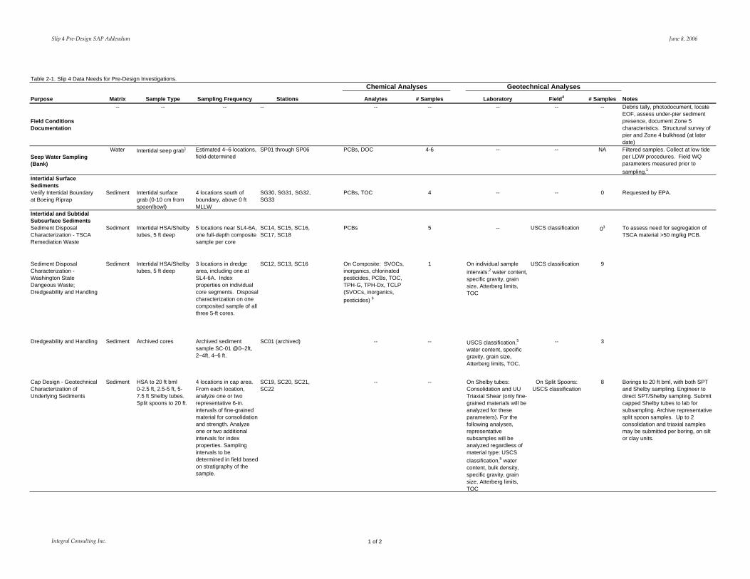
Slip 4 Pre‐Design SAP Addendum June 8 2006
Table 2-1 Slip 4 Data Needs for Pre-Design Investigations Chemical Analyses Geotechnical Analyses
Purpose Matrix Sample Type Sampling Frequency Stations Analytes Samples Laboratory Field4 Samples Notes
Bank Subsurface Soils
Zone 2 Bank ExcavationDisposal Characterization
Bank soils Composite soil sample from hand auger boring or hand-dug test pit
One composite sample from a boring (to 3ndash4 bgs) in Zone 2
SB21 SVOCs inorganics chlorinated pesticides PCBs TOC TPH-G TPH-Dx TCLP (SVOCs inorganics pesticides) 6
1 Water content specific gravity grain size Atterberg limits
USCS classification 1
Zone 3 4 5 Bank Excavation Disposal Characterization
Bank soils Composite soil sample from hand auger borings or hand-dug test pits
One composite sample from borings (to 3ndash4 bgs) in Zone 3 4 and 5
SB22 SB23 SVOCs inorganics chlorinated pesticides PCBs TOC TPH-G TPH-Dx TCLP (SVOCs inorganics pesticides)6
1 Water content specific gravity grain size Atterberg limits
USCS classification 1
Notes surface 1 Field water quality parameters will be measured before sampling at each seep location and in adjacent surface water Parameters include temperature conductivity turbidity dissolved oxygen pH salinity and oxidation-reduction potential 2 Sample target intervals will be from 0ndash2 ft below mudline (bml) 2ndash4 ft bml and 4ndash5 ft bml 3 Geotechnical analyses on samples from SC16 are included under Sediment disposal characterization - Washington State Dangerous Waste 4 USCS classification will be conducted in the field following ASTM D2488 Visual Manual Procedure 5 USCS classification will be conducted by the laboratory following ASTM D2487 6 TCLP aliquots to be archived for potential future analysis -- - not applicable
Integral Consulting Inc 2 of 2
Slip 4 Pre‐Design SAP Addendum June 8 2006
Table 2-2 Slip 4 Proposed Sample Locations for Pre-Design Investigations
Station ID Northing Easting
SC12 1992785071 1273514482 SC13 1993604344 1273429089 SC14 1994268725 1273459595 SC15 1994252542 1273498824 SC16 1994490406 1273482094 SC17 1994657131 1273501524 SC18 199465893 1273468952 SC19 1988678836 1273370448 SC20 1990483314 1273510154 SC21 1992283014 127340771 SC22 1993978931 1273521878 SB21 1994112452 1273410305 SB22 1992791657 1273582561 SB23 1988407995 1273394217 SG30 1988051522 1273345121 SG31 198791841 1273358284 SG32 1987818575 1273352892 SG33 1987902563 1273335606
Notes Horizontal Datum Washington State Plane Coordinate System North Zone (NAD 8391) US feet
Integral Consulting Inc 1
APPENDIX B
STANDARD
OPERATING
PROCEDURES
SOP‐6 Revision 52006
STANDARD OPERATING PROCEDURE 6
Hollow-Stem Auger DrillingSediment Sampling
Scope and Application
Soilsediment cores are collected to evaluate sediment at depths that greatly exceed those achieved by grab or other surface samplers The purpose of this standard operating procedure (SOP) is to define and standardize procedures for core collection using split‐spoon and Shelby tube samplers advanced through hollow‐stem auger borings following American Society for Testing and Materials (ASTM) Method D1586 and Method D1587 respectively The use of Shelby tube samplers or split‐spoon samplers is specified in the Slip 4 Pre‐Design Sampling and Analysis Plan Addendum (Integral 2006) Shelby tubes will be used to recover relatively undisturbed soil samples suitable for laboratory tests of engineering properties such as strength compressibility permeability and density
Required Equipment
bull Sampling and Analysis Plan (SAP)
bull Health and Safety Plan (HSP)
bull Site logbook and boring log
bull Indelible black‐ink pens and markers
bull Camera
bull Hollow‐stem auger drill rig
bull Driller and helper
bull Split‐spoon samplers (typically 2‐in diameter a larger 3‐in diameter 2‐ft‐length split‐spoon may be used to obtain more material from each depth interval)
bull Shelby tube samplers conforming to thin‐walled tube specifications outlined in ASTM D1587 with a 2‐ to 5‐in OD and 5 to 10 times the diameter in length Wax and end caps will also be provided for proper field sealing
bull Photoionization detector (PID)
bull Plastic sheeting
bull 55‐gallon drums (if required)
bull Insulated cooler(s) chain‐of‐custody seals Ziplocreg bags
bull Sample labels and appropriate documentation
Integral Consulting Inc 1
SOP‐6 Revision 52006
bull Assorted geology supplies (eg hand lens grain‐size card scales etc)
bull Decontamination equipment (SOP‐10)
Typical Procedures
1 Ensure underground utilities in vicinity of each boring location have been marked prior to mobilizing drill rig to site
2 Conduct daily site activityhealth and safety briefing
3 Calibrate field instrumentation if applicable
4 Record necessary data in field logbook
5 Obtain photograph(s) of site before drilling
6 Place plastic sheeting andor drums at drilling location to collect cuttings (if necessary)
7 Move equipment and supplies to drilling location
8 Set up decontamination and sampling stations
Split-Spoon Sampling
1 Obtain surface soil samples if required
2 Drill to first sampling depth as described in the SAP
3 Place decontaminated split‐spoon sampler on center rods
4 Drive split‐spoon sampler as described in ASTM Method D‐1586 Drive sampler to 18 inch or to refusal (no progress for 50 blows) Record blow counts on boring log form Retrieve sampler
5 Screen sampler with PID (if required)
6 Describe soil in accordance with ASTM D2488 on the boring log form
7 Composite soil sample as necessary If volatile organic compound (VOC) samples are to be collected collect VOC sample prior to describing soil
8 Continue drilling at next sample location Collect samples as outlined above
9 Label and manage sample containers in accordance with the site‐specific SAP section for shipping and handling of samples
10 Decontaminate sampling equipment in accordance with the site‐specific SAP
11 Document activities in site logbook
12 Backfill or grout borehole as required
Integral Consulting Inc 2
SOP‐6 Revision 52006
13 Move to next location
Shelby Tube Sampling
1 Obtain surface soil samples if required
2 Drill to first sampling depth as described in the SAP
3 Place decontaminated Shelby tube sampler on center rods
4 Drive Shelby tube sampler as described in ASTM Method D1587 Retrieve the sampling tube and remove the disturbed material from the top of the tube In addition remove 1 inch of soil from the base of the tube Place an impervious disk at both ends of the tube seal with a wax plug prior to shipment to the laboratory
5 If Shelby tubes are to be extruded in the field for composite sampling the driller will use a hydraulic extruder to obtain the sample The core is then described in accordance with ASTM Method D2488 on the boring log form Samples will then be composited as necessary for analysis
6 Screen sampler with PID (if required)
7 Label and manage sample containers in accordance with the site‐specific SAP section for shipping and handling of samples The sample tube should be packed in StyrofoamTM plugs or other cushioning material to prevent disturbance of the sample
8 Continue drilling to next sample location Collect samples as outlined above
9 Decontaminate sampling equipment in accordance with the site‐specific SAP section
10 Document activities in site logbook
11 Backfill or grout borehole as required
12 Move to next location
Reference
Integral 2006 Lower Duwamish Waterway Slip 4 Early Action Area Sampling and Analysis Plan for Boundary Definition Addendum Pre‐Design Investigation Sampling Prepared for Seattle City Light and King County Seattle WA Integral Consulting Inc Mercer Island WA
Integral Consulting Inc 3
APPENDIX C
QAPP ADDENDUM
LOWER DUWAMISH WATERWAY
SLIP 4 EARLY ACTION AREA
Quality Assurance Project Plan for Boundary Definition
Addendum Pre‐Design Investigation Sampling
Submitted to US Environmental Protection Agency Region 10
1200 Sixth Avenue Seattle WA 98101
Submitted by City of Seattle King County
Prepared by
7900 SE 28th Street Suite 300 Mercer Island WA 98040
June 8 2006
Pre‐Design QAPP Addendum June 8 2006
A PROJECT MANAGEMENT
A1 TITLE AND APPROVAL SHEET
QUALITY ASSURANCE PROJECT PLAN FOR BOUNDARY DEFINITION
PRE‐DESIGN INVESTIGATION SAMPLING ADDENDUM
LOWER DUWAMISH WATERWAY SLIP 4 EARLY ACTION AREA
SEATTLE WASHINGTON
Quality Assurance Project Plan Approvals
EPA Project Coordinator Karen Keeley Date
EPA QA Manager Ginna Grepo‐Grove Date
City of Seattle Project Manager Jennie Goldberg Date
Integral Principal in Charge Betsy Day Date
Integral Project Manager David Schuchardt Date
Integral Project QA Coordinator Reid Carscadden Date
ARI Project Manager Sue Dunnihoo Date
ARI QA Manager Dave Mitchell Date
Integral Consulting Inc ii
Pre‐Design QAPP Addendum June 8 2006
This page intentionally left blank
Integral Consulting Inc iii
Pre‐Design QAPP Addendum June 8 2006
A2 TABLE OF CONTENTS
A PROJECT MANAGEMENT ii A1 TITLE AND APPROVAL SHEET ii A2 TABLE OF CONTENTS iv A3 DISTRIBUTION LIST vii A4 INTRODUCTION AND PROJECT AND TASK ORGANIZATION1
A41 Introduction1 A42 Project and Task Organization1
A5 PROBLEM DEFINITION AND BACKGROUND1 A6 TASK DESCRIPTION 2 A7 QUALITY OBJECTIVES AND CRITERIA FOR MEASUREMENT DATA3
SECTION B DATA GENERATION AND ACQUISITION5 B1 SAMPLING PROCESS DESIGN 5 B2 SAMPLING METHODS7 B3 SAMPLE HANDLING AND CUSTODY7 B4 ANALYTICAL METHODS7 B5 QUALITY CONTROL 7
B51 Field Quality Control Samples 7
REFERENCES9
Integral Consulting Inc iv
Pre‐Design QAPP Addendum June 8 2006
LIST OF FIGURES Figure A4‐1 Organization Chart
LIST OF TABLES Table A4‐1 Project Team Contact Information Table A6‐1 Estimated Numbers of Pre‐Design Samples by Sample Type Table A6‐2 Target Analytes Methods and Method Reporting Limits for Pre‐Design
Investigation Samples Table A7‐1 Measurement Quality Objectives Table B2‐1 Sample Containers Preservation Holding Times and Sample Volume
Integral Consulting Inc v
Pre‐Design QAPP Addendum June 8 2006
ACRONYMS AND ABBREVIATIONS ARI Analytical Resources Inc ASTM American Society for Testing and Materials bml below the mudline DOC dissolved organic carbon DQOs data quality objectives EDD electronic data deliverables EECA engineering evaluationcost analysis EPA US Environmental Protection Agency EQuIS Environmental Quality Information System LDW Lower Duwamish Waterway MDLs method detection limits MQOs measurement quality objectives MRLs method reporting limits MS mass spectrometry PCB polychlorinated biphenyl PSEP Puget Sound Estuary Program QAPP quality assurance project plan QC quality control SAP sampling and analysis plan SVOCs semivolatile organic compounds TCLP Toxicity Characteristic Leaching Procedure TOC total organic carbon TPH total petroleum hydrocarbon TPH‐Dx extended diesel‐range total petroleum hydrocarbon TPH‐G gasoline‐range total petroleum hydrocarbon TSCA Toxic Substances Control Act USCS Unified Soil Classification System
Integral Consulting Inc vi
Pre‐Design QAPP Addendum June 8 2006
A3 DISTRIBUTION LIST
US EPA Region 10 Remedial Project Manager Karen Keeley
US EPA QA Manager Ginna Grepo‐Grove
City of Seattle Project Coordinator Jennie Goldberg
Integral Principal in Charge Betsy Day
Integral Project Manager David Schuchardt Integral Project QA Coordinator Reid Carscadden
Integral Field Coordinator Jane Sund or Susan FitzGerald
Integral Laboratory Coordinator amp QA Manager Maja Tritt Integral Data Manager Tom Schulz
ARI Project Manager Sue Dunnihoo
ARI QA Manager Dave Mitchell
Integral Consulting Inc vii
Pre‐Design QAPP Addendum June 8 2006
A4 INTRODUCTION AND PROJECT AND TASK ORGANIZATION
A41 Introduction
This quality assurance project plan (QAPP) addendum describes procedures that will be used to complete a pre‐design investigation to characterize seep water sediment and bank soil in the Slip 4 Early Action Area of the Lower Duwamish Waterway (LDW) This addendum supplements the Boundary Definition QAPP (Integral 2004a) The Boundary Definition QAPP describes procedures and requirements for the generation of data of documented acceptable quality that will be used for the pre‐design investigation This Pre‐Design QAPP Addendum addresses procedures that will be used for the pre‐design investigation that are not described in the Boundary Definition QAPP
Supplemental information to Sections A and B of the Boundary Definition QAPP is provided in this Pre‐Design QAPP Addendum Special training and certification and documents and records are described in Sections A8 and A9 respectively of the Boundary Definition QAPP and are not addressed further in this QAPP addendum
Procedures for project assessment and oversight will be completed as described in Section C of the Boundary Definition QAPP
All data for organic inorganic and conventional analytes including total solids used for dry‐weight conversions will be verified and validated Data for geotechnical characteristics do not require validation because of the mechanical nature of these tests Data verification and validation and data quality assessment procedures will be completed as described in Section D of the Boundary Definition QAPP
A42 PROJECT AND TASK ORGANIZATION
The organizational structure for this project is illustrated in Figure A4‐1 Contact information related to the pre‐design investigation is provided in Table A4‐1 of this QAPP addendum Project and quality assurance responsibilities are described in detail in Section 31 of the Boundary Definition sampling and analysis plan (SAP) and Pre‐Design SAP Addendum (Integral 2004b and 2006b respectively)
A5 PROBLEM DEFINITION AND BACKGROUND
The primary objective of this Slip 4 pre‐design investigation is to fill identified data gaps to support the design of the removal action alternative recommended by the City of Seattle and King County as presented in the engineering evaluationcost analysis (EECA) (Integral 2006a) Data will be collected to support the following activities
Integral Consulting Inc 1
Pre‐Design QAPP Addendum June 8 2006
bull Verification of the removal boundary bull Characterization of seep water bull Dredging evaluation of the removal area bull Characterization of removal area sediment and bank soil for disposal bull Geotechnical characterization of the capping area
Sampling activities will include collection of seep samples surface and subsurface sediment samples and subsurface bank samples Details are provided in Sections 21 and 22 of the Pre‐Design SAP Addendum
A6 TASK DESCRIPTION
The tasks to be completed for this project include fieldwork laboratory analyses data quality evaluation data management data analysis and report preparation The Slip 4 pre‐design elements include a field conditions survey seep water sampling intertidal surface sediment sampling subsurface bank soil sampling and subsurface sediment coring The methods to be used for the collection of these samples are described in Section 33 of the Pre‐Design SAP Addendum All field documentation station positioning sample handling equipment decontamination waste disposal chain‐of‐custody and quality control procedures will follow those described in the Boundary Definition SAP (Integral 2004b) except where noted in the Pre‐Design SAP Addendum
Integral will collect the various sediment bank soil and seep water samples and prepare samples for delivery to the laboratory Susan FitzGerald or Jane Sund of Integral will serve as field coordinator and will assume custody of cores and samples as they are collected A list of samples and analyses is provided in Table A6‐1 Sample locations are provided in Figure 2‐2 of the Pre‐Design SAP Addendum (Integral 2006b)
Samples will undergo chemical and geotechnical testing by Analytical Resources Inc (ARI Seattle WA) for analytes listed in Table A6‐2 Analyses will be completed using US Environmental Protection Agency (EPA) American Society for Testing and Materials (ASTM) and Puget Sound Estuary Program (PSEP) methods (USEPA 2003 PSEP 1986 1997ab ASTM 2003) as indicated in Table A6‐2 Full laboratory data reports will be provided in hardcopy and electronic data deliverables (EDDs) will be provided in spreadsheet format as required for importing into the database The Environmental Quality Information System (EQuIS) database application will be used to manage the field and laboratory data Data will also be submitted electronically to EPA in SEDQUAL format
Data verification will be completed by Integral for data generated in the field and by ARI for data generated at the laboratory The accuracy and completeness of the final database will be verified by Integral Data validation and data quality assessment will be
Integral Consulting Inc 2
Pre‐Design QAPP Addendum June 8 2006
completed by an independent validation firm which will be selected at a later date The validation firm will also complete data verification (ie verifying that analytical procedures and calculations were completed correctly and checking transcriptions of the laboratory data) for the first data package for each analysis as part of the full validation that will be completed for these packages
The results of the Pre‐Design SAP Addendum field sampling will be presented in the 60 Design Documents for the Slip 4 Early Action currently scheduled for completion in fall 2006
The start date for field sampling will be determined following EPA approval of the project SAP and QAPP addenda and pending property access permission from property owners Currently it is anticipated that field sampling will begin in June 2006 The field and reporting schedules are discussed further in Sections 32 and 44 respectively of the Pre‐Design SAP Addendum
A7 QUALITY OBJECTIVES AND CRITERIA FOR MEASUREMENT DATA
Data quality objectives (DQOs) for the pre‐design investigation are described in Section A7 of the Boundary Definition QAPP Target method reporting limits (MRLs) and method detection limits (MDLs) for this project are summarized in Table A6‐2 Measurement quality objectives (MQOs) for this project are summarized in Table A7‐1 Analyte concentrations for this project will be reported to the MDL as described in the Boundary Definition QAPP
Integral Consulting Inc 3
Pre‐Design QAPP Addendum June 8 2006
This page intentionally left blank
Integral Consulting Inc 4
Pre‐Design QAPP Addendum June 8 2006
SECTION B DATA GENERATION AND ACQUISITION
B1 SAMPLING PROCESS DESIGN
This section supplements Section B1 of the Boundary Definition QAPP The sampling effort for this study will include the collection of seep water surface sediment subsurface sediment and subsurface bank soil from Slip 4 in the LDW
Seep water will be collected as discrete samples from individual seep locations (to be determined in the field) Water quality parameters (conductivity turbidity temperature dissolved oxygen pH salinity and oxidation‐reduction potential) will be measured in the field at each seep and in adjacent surface water prior to sample collection Seep samples will be filtered in the field through 10‐μm glass filters and submitted for laboratory analysis for polychlorinated biphenyl (PCB) Aroclors and dissolved organic carbon (DOC)
Surface sediment samples will be collected from the 0ndash10 cm interval at four locations and will be analyzed for total organic carbon (TOC) and PCB Aroclors
All subsurface soil samples will be characterized according to the Unified Soil Classification System (USCS) as per current annual American Society for Testing and Materials (ASTM) Methods This visualmanual classification will occur in the field per ASTM D2488 and will be recorded on boring logs except where undisturbed samples for geotechnical characterization are submitted to the laboratory For those samples the laboratory will perform the USCS classification following ASTM D2487 Field USCS classification is not considered an ldquoanalysisrdquo in the QAPP
Sediment cores from 0 to 5 ft below the mudline (bml) will be collected from seven locations to characterize sediment in the area to be dredged Chemical analyses will be required on six samples as follows
bull One composite sample representing the entire 0‐ to 5‐ft lengths of cores from three of the locations will be submitted for chemical analysis to evaluate whether the material will require disposal as a Washington State Dangerous Waste Analysis of this sample will include PCB Aroclors chlorinated pesticides semivolatile organic compounds (SVOCs) metals extended diesel‐range total petroleum hydrocarbons (TPH‐Dx) gasoline‐range TPH (TPH‐G) and TOC An additional aliquot of this sample will be archived for potential future Toxicity Characteristic Leaching Procedure (TCLP) analyses for SVOCs chlorinated pesticides and metals
Integral Consulting Inc 5
Pre‐Design QAPP Addendum June 8 2006
bull Five samples representing the 0‐ to 5‐ft lengths of five discrete cores near the head of the slip will be submitted for PCB Aroclor analysis to determine if segregation of an area potentially requiring disposal under the Toxic Substances Control Act (TSCA) regulations is practicable
The cores will also be subsampled into three sample intervals (0ndash2 ft bml 2ndash4 ft bml and 4ndash5 ft bml) These discrete samples will be analyzed for geotechnical parameters as follows
bull Nine subsamples from three cores (SC12 SC13 and SC16) representing the area to be dredged will be analyzed for grain‐size distribution water content specific gravity Atterberg limits and TOC One of the cores in this group (SC16) is located in the potential TSCA area
bull Three archived samples from SC01 (0ndash2 ft 2ndash4 ft and 4ndash6 ft) collected in 2004 will be analyzed for grain‐size distribution water content USCS classification specific gravity Atterberg limits and TOC
Samples of bank soil from bank removal areas are needed to characterize the material for disposal Two composite samples will be collected using hand auger boring or hand dug test pit one sample from Zone 2 and one sample from Zones 3 4 and 5 These samples will be submitted for chemical and geotechnical analyses Chemical analytes will include PCB Aroclors chlorinated pesticides SVOCs metals TPH‐Dx TPH‐G TOC and TCLP analysis for SVOCs chlorinated pesticides and metals Samples collected for TCLP analysis of SVOCs metals and chlorinated pesticides will be archived at the laboratory and analysis will be contingent on the results of dry‐weight analysis TCLP analysis will only need to be performed when the TCLP contaminants in the results from the total analysis are greater than or equal to 20 times the maximum concentration for toxicity characteristic regulatory levels (set forth in Table 1 of 40 CFR 26124) The ldquo20 times rulerdquo is allowable because of the sample dilution that is a component of the TCLP Method 1311 (Section 12 of this method) as is clarified in EPA 540‐R‐94‐005a Geotechnical analyses will include grain‐size distribution water content specific gravity Atterberg limits and TOC
Sediment samples from four cores will be collected for geotechnical analyses to determine the consolidation properties strength and bearing capacity of the underlying sediments These samples will be analyzed by consolidation testing unconsolidated undrained (UU) triaxial shear grain‐size distribution USCS classification water content bulk density specific gravity Atterberg limits and TOC
Field quality control (QC) samples will be collected for chemical analysis as specified in the QAPP (Integral 2004a) with the exception that field duplicate cores will not be
Integral Consulting Inc 6
Pre‐Design QAPP Addendum June 8 2006
collected Field QC samples are described in Section 36 of the Boundary Definition SAP (Integral 2004b) and Section 34 of the Pre‐Design SAP Addendum (Integral 2006b)
B2 SAMPLING METHODS
This section supplements Section B2 of the Boundary Definition QAPP
Seep samples will be collected using either a funnel or peristaltic pump with attached dedicated disposal tubing Intertidal surface sediment will be collected using stainless‐steel bowls and spoons Subsurface sediment cores for dredge area characterization and for geotechnical evaluation will be collected using Shelby tubes and split‐spoon samplers advanced through hollow‐stem augers using a barge‐mounted drill rig Subsurface bank soil samples will be collected using hand augers or hand‐dug test pits Sampling methods are described in Section 33 of the Pre‐Design SAP Addendum Requirements for sample containers storage temperature and holding times for sediment and seep water samples are summarized in Table B2‐1 of this Pre‐Design QAPP Addendum
B3 SAMPLE HANDLING AND CUSTODY
Sample handling and custody procedures will be completed as described in Section 334 of the Pre‐Design SAP Addendum (Integral 2006b)
B4 ANALYTICAL METHODS
Analyses will be completed according to the methods provided in Table A6‐2 These methods will be modified in some cases as described in the Boundary Definition QAPP Sediment samples will be analyzed for SVOCs by full‐scan mass spectrometry (MS) Selected ion monitoring will not be used because the sensitivity of full‐scan MS is sufficient to meet the study objectives
B5 QUALITY CONTROL
Quality control samples will be prepared in the field and at the laboratories to monitor the bias and precision of the sample collection and analysis procedures Field quality control samples are described below Laboratory quality control will be completed as described in the Boundary Definition QAPP
B51 Field Quality Control Samples
Field QC samples for the pre‐design investigation will include field duplicates (for surface sediment sampling) field replicates (for seep sampling) and equipment rinse blanks (for
Integral Consulting Inc 7
Pre‐Design QAPP Addendum June 8 2006
seep and surface sediment sampling) Field QC samples will be collected at a minimum for seep and surface sediment samples at a frequency of 5 percent of the sample total The procedures for preparing field replicates duplicates and rinse blanks are presented in Section 36 of the Boundary Definition SAP (Integral 2004b) and Section 34 of the Pre‐Design SAP Addendum (Integral 2006b) Validation criteria and procedures for field QC samples are described in Sections D1 and D2 of the Boundary Definition QAPP (Integral 2004a)
Integral Consulting Inc 8
Pre‐Design QAPP Addendum June 8 2006
REFERENCES
ASTM 2003 Annual Book of ASTM Standards Volume 0408 American Society for Testing and Materials Philadelphia PA
Integral 2004a Lower Duwamish Waterway Slip 4 Early Action Area Quality Assurance Project Plan for Boundary Definition Prepared for Seattle City Light and King County Seattle WA Integral Consulting Inc Mercer Island WA
Integral 2004b Lower Duwamish Waterway Slip 4 Early Action Area Sampling and Analysis Plan for Boundary Definition Prepared for City of Seattle and King County WA Integral Consulting Inc Mercer Island WA
Integral 2006a Lower Duwamish Waterway Slip 4 Early Action Area Engineering EvaluationCost Analysis Submitted to US EPA Region 10 City of Seattle King County Seattle WA Integral Consulting Inc Mercer Island WA
Integral 2006b Lower Duwamish Waterway Slip 4 Early Action Area Sampling and Analysis Plan for Boundary Definition Addendum Pre‐Design Investigation Sampling Prepared for Seattle City Light and King County Seattle WA Integral Consulting Inc Mercer Island WA
Plumb Jr RH 1981 Procedures for Handling and Chemical Analysis of Sediment and Water Samples Technical Report EPACE‐81‐1 Prepared by Great Lakes Laboratory State University College at Buffalo Buffalo NY for the US Environmental Protection AgencyUS Army Corps of Engineers Technical Committee on Criteria for Dredged and Fill Material Published by the US Army Engineer Waterways Experiment Station CE Vicksburg MS
PSEP 1986 Puget Sound Estuary Program Recommended Protocols for Measuring Conventional Sediment Variables in Puget Sound Final Report TC‐3991‐04 Prepared for US Environmental Protection Agency Region 10 Seattle WA Tetra Tech and HRA Inc Bellevue WA (minor corrections April 2003)
PSEP 1997a Puget Sound Estuary Program Recommended Guidelines for Measuring Organic Compounds in Puget Sound Water Sediment and Tissue Samples In Recommended Protocols for Measuring Selected Environmental Variables in Puget Sound Puget Sound Action Team Olympia WA
Integral Consulting Inc 9
Pre‐Design QAPP Addendum June 8 2006
PSEP 1997b Puget Sound Estuary Program Recommended Quality Assurance and Quality Control Guidelines for the Collection of Environmental Data in Puget Sound In Recommended Protocols for Measuring Selected Environmental Variables in Puget Sound Puget Sound Action Team Olympia WA
USEPA 2003 SW‐846 On‐line Test Methods for Evaluating Solid Waste ‐PhysicalChemical Methods US Environmental Protection Agency httpwwwepagovepaoswerhazwastetestmainhtm Accessed January 8 2004
Windward 2004 Data Report Survey and Sampling of Lower Duwamish Waterway Seeps Prepared for Lower Duwamish Waterway Group for submittal to US Environmental Protection Agency and Washington State Department of Ecology Windward Environmental LLC Seattle WA
Integral Consulting Inc 10
FIGURE
EPA Region 10
Remedial Project Manager Karen Keeley
Principal In Charge Betsy Day
Project Manager Dave Schuchardt
Integral Laboratory Coordinator
amp QA Manager Maja Tritt
EPA QA Manger Ginna Grepo-Grove
Project QA Coordinator Ried Carscadden
Data Management Tom Schulz
Field Coordinator Jane Sund or Susan FitzGerald
City of Seattle
Project Coordinator Jennie Goldberg
Data Validation Firm
to be determined
Analytical Resources Inc
Project Manager Sue Dunnihoo
Cascade Drilling
Figure A4-1 Organization Chart
TABLES
Slip 4 Pre‐Design QAPP Addendum June 8 2006
Table A4-1 Project Team Contact Information
Organization EPA Region 10
Individual Karen Keeley Ginna Grepo-Grove
Project Role Project Coordinator QA Manager
Phone 206-553-2141 206-553-1632
Fax 206-553-0124 206-553-8210
Email KeeleyKarenepagov Grepo-GroveGinaepagov
City of Seattle Jennie Goldberg SCL Project Coordinator 206-684-3167 206-386-4589 jenniegoldbergseattlegov
Integral Consulting Betsy Day David Schuchardt Reid Carscadden Jane Sund or Susan FitzGerald Ian Stupakoff
Principal in Charge Project Manager Project QA Coordinator
Field Coordinator
Field Staff
206-957-0346 206-957-0350 206-957-0343 503-284-5545 ext15 or 206-957-0352 360-705-3534 360-259-2518
206-230-9601 206-230-9601 206-230-9601 503-284-5755 or 206-230-9601
360-705-3669
bdayintegral-corpcom dschuchardtintegral-corpcom rcarscaddenintegral-corpcom jsundintegral-corpcom sfitzgeraldintegral-corpcom istupakoffintegral-corpcom
Maja Tritt Tom Schulz
Laboratory CoordinatorQA Manager Data Manager
206-957-0353 360-705-3534 ext17
206-230-9601 360-705-3669
mtrittintegral-corpcom tschulzintegral-corpcom
Analytical Resources Inc (ARI)
Sue Dunnihoo Dave Mitchell
Laboratory Project Manager Laboratory QA Manager
206-695-6207 206-695-6205
206-621-7523 206-621-7523
suedarilabscom davemarilabscom
Integral Consulting Inc 1 of 1
Slip 4 Pre‐Design QAPP Addendum June 8 2006
Table A6-1 Estimated Numbers of Pre-Design Samples by Sample Type
Total Number Number of Field Field Equipment of Field
Sample Type and Analysis Samples1 Duplicates2 Replicates2 Rinse Blanks Samples
Seep WaterPCB Aroclors 4ndash6 0 1 1 6ndash8 DOC 4ndash6 0 1 1 6ndash8
Surface Sediment PCB Aroclors 4 1 0 1 6 Total Organic Carbon 4 1 0 NA 5
Subsurface Sediment PCB Aroclors 6 0 0 0 6 SVOCs 1 0 0 0 1 Metals 1 0 0 0 1 Chlorinated Pesticides 1 0 0 0 1 TPH-Dx 1 0 0 0 1 TPH-G 1 0 0 0 1 TCLP SVOCs 3 1 0 0 NA 1 TCLP Metals 3 1 0 0 NA 1 TCLP Chlorinated Pesticides 3 1 0 0 NA 1 Grain-Size Distribution 20 0 0 NA 20 Total Organic Carbon 20 0 0 NA 20 Water Content 20 0 0 NA 20 Bulk Density 8 0 0 NA 8 Specific Gravity 20 0 0 NA 20 Atterberg limits 20 0 0 NA 20 USCS Classification 4 11 0 0 NA 11 Consolidation 8 NA 0 NA 8 UU Triaxial Shear 8 NA 0 NA 8
Subsurface Sediment (Archived Analysis) Grain-Size Distribution 3 0 0 NA 3 Total Organic Carbon 3 0 0 NA 3 Water Content 3 0 0 NA 3 Bulk Density 0 0 0 NA 0 Specific Gravity 3 0 0 NA 3 Atterberg Limits 3 0 0 NA 3 USCS Classification 4 3 0 0 NA 3
Subsurface Bank Soil PCB Aroclors 2 0 0 0 2 SVOCs 2 0 0 0 2 Metals 2 0 0 0 2 Chlorinated Pesticides 2 0 0 0 2 TPH-Dx 2 0 0 0 2 TPH-G 2 0 0 0 2 TCLP SVOCs 3 2 0 0 NA 2 TCLP Metals 3 2 0 0 NA 2 TCLP Chlorinated Pesticides 3 2 0 0 NA 2 Grain-Size Distribution 2 0 0 NA 2
Integral Consulting Inc 1 of 2
Slip 4 Pre‐Design QAPP Addendum June 8 2006
Table A6-1 Estimated Numbers of Pre-Design Samples by Sample Type
Total Number Number of Field Field Equipment of Field
Sample Type and Analysis Samples1 Duplicates2 Replicates2 Rinse Blanks Samples
Total Organic Carbon 2 0 0 NA 2 Water Content 2 0 0 NA 2 Bulk Density 0 0 0 NA 0 Specific Gravity 2 0 0 NA 2 Atterberg Limits 2 0 0 NA 2
Notes DOC = dissolved organic carbon PCB = polychlorinated biphenyls SVOCs = semivolatile organic compounds TCLP = Toxicity Characteristic Leaching Procedure TPH-Dx = total petroleum hydrocarbons diesel- and oil-range1 Numbers are based on the Pre-Design SAP Addendum Integral 2006b Table 2-12 Duplicate replicate and rinsate samples will not be collected for waste disposal characterization samples 3 TCLP samples will be archived for potential future analysis 4 Only laboratory USCS Classification samples by ASTM D2487 are shown
Integral Consulting Inc 2 of 2
Slip 4 Pre‐Design QAPP Addendum June 8 2006
Table A6-2 Target Analytes Methods and Method Reporting Limits for Pre-Design Investigation Samples
Analyte Sample Preparation Method Sample Cleanup Method1 Analysis Method MDL MRL
Seep Water PCB Aroclors (ugL)
Dissolved Organic Carbon (mgL)
ARI Low Level (Modified EPA 3510)
EPA 4151
EPA 3660B (sulfur) EPA 3665A (acid)
EPA 3630C (silica gel) optional2
--
GCECD (EPA 8082)3
Direct combustion (EPA 4151)
0005
0018
001
002
Sediments and Bank Soils Conventional analytes
USCS Classification -- -- ASTM D-2487 -- --Grain Size ( dry wt) TOC ( dry wt)
----
----
PSEP (1986) Plumb (1981)
--0018
01 002
Geotechnical Charactersitics Atterberg limits ( moisture) Specific gravity (gcc) Water content (percent) Bulk density (gcc) Consolidation
----------
----------
ASTM D-4318 ASTM D-854
ASTM D-2216 ASTM D-2937
ASTM D-2435 Method B
----------
01 001 01 01 --
UU Triaxial Shear -- -- ASTM D-2850 -- --
PCB Aroclors (ugkg dry weight) ARI Low Level (EPA 3550B-mod) EPA 3660B (sulfur) optional2
EPA 3665A (acid) optional2 GCECD (EPA 8082)3 04 40
Pesticides (ugkg dry weight) 44rsquo-DDT 44rsquo-DDE 44rsquo-DDD 24rsquo-DDT 24rsquo-DDE 24rsquo-DDD Aldrin alpha-BHC beta-BHC delta-BHC gamma-BHC Oxychlordane alpha-chlordane gamma-chlordane cis-nonachlor
Sonication (EPA 3550B) Sonication (EPA 3550B) Sonication (EPA 3550B) Sonication (EPA 3550B) Sonication (EPA 3550B) Sonication (EPA 3550B) Sonication (EPA 3550B) Sonication (EPA 3550B) Sonication (EPA 3550B) Sonication (EPA 3550B) Sonication (EPA 3550B) Sonication (EPA 3550B) Sonication (EPA 3550B) Sonication (EPA 3550B) Sonication (EPA 3550B)
EPA 3660BEPA3630C EPA 3660BEPA3630C EPA 3660BEPA3630C EPA 3660BEPA3630C EPA 3660BEPA3630C EPA 3660BEPA3630C EPA 3660BEPA3630C EPA 3660BEPA3630C EPA 3660BEPA3630C EPA 3660BEPA3630C EPA 3660BEPA3630C EPA 3660BEPA3630C EPA 3660BEPA3630C EPA 3660BEPA3630C EPA 3660BEPA3630C
EPA 8081A EPA 8081A EPA 8081A EPA 8081A EPA 8081A EPA 8081A EPA 8081A EPA 8081A EPA 8081A EPA 8081A EPA 8081A EPA 8081A EPA 8081A EPA 8081A EPA 8081A
0199 0125 0095 0091 0033 0037 0044 0051 0091 0021 009
0123 0058 012 055
20 20 20 20 20 20 10 10 10 10 10 20 10 10 20
Integral Consulting Inc 1 of 4
Slip 4 Pre‐Design QAPP Addendum June 8 2006
Table A6-2 Target Analytes Methods and Method Reporting Limits for Pre-Design Investigation Samples
Analyte Sample Preparation Method Sample Cleanup Method1 Analysis Method MDL MRL
trans-nonachlor Sonication (EPA 3550B) EPA 3660BEPA3630C EPA 8081A 0024 20 Dieldrin Sonication (EPA 3550B) EPA 3660BEPA3630C EPA 8081A 0085 20 Endosulfan Sonication (EPA 3550B) EPA 3660BEPA3630C EPA 8081A 0063 10 Endosulfan II Sonication (EPA 3550B) EPA 3660BEPA3630C EPA 8081A 0125 20 Endosulfan sulfate Sonication (EPA 3550B) EPA 3660BEPA3630C EPA 8081A 0148 20 Endrin Sonication (EPA 3550B) EPA 3660BEPA3630C EPA 8081A 0082 20 Endrin aldehyde Sonication (EPA 3550B) EPA 3660BEPA3630C EPA 8081A 0184 20 Heptachlor Sonication (EPA 3550B) EPA 3660BEPA3630C EPA 8081A 0073 10 Heptachlor epoxide Sonication (EPA 3550B) EPA 3660BEPA3630C EPA 8081A 0054 10 Hexachlorobenzene Sonication (EPA 3550B) EPA 3660BEPA3630C EPA 8081A 0066 10 Methoxychlor Sonication (EPA 3550B) EPA 3660BEPA3630C EPA 8081A 112 100 Mirex Sonication (EPA 3550B) EPA 3660BEPA3630C EPA 8081A 0013 20 Toxaphene Sonication (EPA 3550B) EPA 3660BEPA3630C EPA 8081A 296 1000
Metals (mgkg) Arsenic EPA 3050 -- EPA 6010B 078 50 Cadmium EPA 3050 -- EPA 6010B 004 02 Chromium EPA 3050 -- EPA 6010B 009 05 Copper EPA 3050 -- EPA 6010B 006 02 Lead EPA 3050 -- EPA 6010B 011 20 Mercury EPA 7471A -- EPA 7471A 0003 005 Silver EPA 3050 -- EPA 6010B 004 03 Zinc EPA 3050 -- EPA 6010B 034 06
Semivolatiles (mgkg) 124-Trichlorobenzene EPA 3550B EPA 3640A EPA 8270C - PSEP (Full scan) 953 20 12-Dichlorobenzene EPA 3550B EPA 3640A EPA 8270C - PSEP (Full scan) 115 20 13-Dichlorobenzene EPA 3550B EPA 3640A EPA 8270C - PSEP (Full scan) 84 20 14-Dichlorobenzene EPA 3550B EPA 3640A EPA 8270C - PSEP (Full scan) 103 20 24-Dimethylphenol EPA 3550B EPA 3640A EPA 8270C - PSEP (Full scan) 63 20 2-Methylnaphthalene EPA 3550B EPA 3640A EPA 8270C - PSEP (Full scan) 183 20 2-Methylphenol EPA 3550B EPA 3640A EPA 8270C - PSEP (Full scan) 679 20 4-Methylphenol EPA 3550B EPA 3640A EPA 8270C - PSEP (Full scan) 73 20 Acenapthene EPA 3550B EPA 3640A EPA 8270C - PSEP (Full scan) 104 20 Acenapththylene EPA 3550B EPA 3640A EPA 8270C - PSEP (Full scan) 938 20 Anthracene EPA 3550B EPA 3640A EPA 8270C - PSEP (Full scan) 795 20 Benz[a]anthracene EPA 3550B EPA 3640A EPA 8270C - PSEP (Full scan) 867 20 Benzo[a]pyrene EPA 3550B EPA 3640A EPA 8270C - PSEP (Full scan) 805 20
Integral Consulting Inc 2 of 4
Slip 4 Pre‐Design QAPP Addendum June 8 2006
Table A6-2 Target Analytes Methods and Method Reporting Limits for Pre-Design Investigation Samples
Analyte Sample Preparation Method Sample Cleanup Method1 Analysis Method MDL MRL
Benzo[b+j+k]fluoranthene EPA 3550B EPA 3640A EPA 8270C - PSEP (Full scan) 863 20 Benzo[ghi]perylene EPA 3550B EPA 3640A EPA 8270C - PSEP (Full scan) 85 20 Benzoic acid EPA 3550B EPA 3640A EPA 8270C - PSEP (Full scan) 89 200 Benzyl alcohol EPA 3550B EPA 3640A EPA 8270C - PSEP (Full scan) 147 20 Bis[2-ethylhexyl]phthalate EPA 3550B EPA 3640A EPA 8270C - PSEP (Full scan) 11 20 Butyl benzyl phthalate EPA 3550B EPA 3640A EPA 8270C - PSEP (Full scan) 91 20 Chrysene EPA 3550B EPA 3640A EPA 8270C - PSEP (Full scan) 97 20 Dibenz[ah]anthracene EPA 3550B EPA 3640A EPA 8270C - PSEP (Full scan) 85 20 Dibenzofuran EPA 3550B EPA 3640A EPA 8270C - PSEP (Full scan) 17 20 Diethyl phthalate EPA 3550B EPA 3640A EPA 8270C - PSEP (Full scan) 106 20 Dimethyl phthalate EPA 3550B EPA 3640A EPA 8270C - PSEP (Full scan) 94 20 Di-n-butyl phthalate EPA 3550B EPA 3640A EPA 8270C - PSEP (Full scan) 66 20 Di-n-octyl phthalate EPA 3550B EPA 3640A EPA 8270C - PSEP (Full scan) 101 20 Fluoranthene EPA 3550B EPA 3640A EPA 8270C - PSEP (Full scan) 86 20 Fluorene EPA 3550B EPA 3640A EPA 8270C - PSEP (Full scan) 116 20 Hexachlorobenzene EPA 3550B EPA 3640A EPA 8270C - PSEP (Full scan) 104 20 Hexachlorobutadiene EPA 3550B EPA 3640A EPA 8270C - PSEP (Full scan) 92 20 Hexachloroethane EPA 3550B EPA 3640A EPA 8270C - PSEP (Full scan) 97 20 Indeno[123-cd]pyrene EPA 3550B EPA 3640A EPA 8270C - PSEP (Full scan) 62 20 Naphthalene EPA 3550B EPA 3640A EPA 8270C - PSEP (Full scan) 117 20 N -nitrosodiphenylamine EPA 3550B EPA 3640A EPA 8270C - PSEP (Full scan) 87 20 Pentachlorophenol EPA 3550B EPA 3640A EPA 8270C - PSEP (Full scan) 473 100 Phenanthrene EPA 3550B EPA 3640A EPA 8270C - PSEP (Full scan) 103 20 Phenol EPA 3550B EPA 3640A EPA 8270C - PSEP (Full scan) 122 20 Pyrene EPA 3550B EPA 3640A EPA 8270C - PSEP (Full scan) 94 20
Total Petroleum Hydrocarbons (mgkg dry weight) Diesel-Range Hydrocarbons NWTPH-Dx EPA 3550B NWTPH-Dx 094 50 Oil-Range Hydrocarbons EPA 3630C silica gel (as needed) 211 100 Gasoline-range hydrocarbons NWTPH-G Methanol extraction NWTPH-G 318 50
Purge and trap
TCLP Metals (mgL) Arsenic EPA 1311 -- EPA 6010B 059 50 Barium EPA 1311 -- EPA 6010B 002 02 Cadmium EPA 1311 -- EPA 6010B 011 05 Chromium EPA 1311 -- EPA 6010B 004 02 Lead EPA 1311 -- EPA 6010B 006 20
Integral Consulting Inc 3 of 4
Slip 4 Pre‐Design QAPP Addendum June 8 2006
Table A6-2 Target Analytes Methods and Method Reporting Limits for Pre-Design Investigation Samples
Analyte Sample Preparation Method Sample Cleanup Method1 Analysis Method MDL MRL
Mercury EPA 1311 -- EPA 7471A 00004 01 Selenium EPA 1311 -- EPA 6010B 004 03 Silver EPA 1311 -- EPA 6010B 017 06
TCLP Semivolatiles (mgL) 14-Dichlorobenzene EPA 1311 followed by EPA 3510C -- EPA 8270C (15) 000217 0005 245-Trichlorophenol EPA 1311 followed by EPA 3510C -- EPA 8270C (15) 000115 0025 246-Trichlorophenol EPA 1311 followed by EPA 3510C -- EPA 8270C (15) 00013 0025 24-Dinitrotoluene EPA 1311 followed by EPA 3510C -- EPA 8270C (15) 000157 0025 Hexachlorobenzene EPA 1311 followed by EPA 3510C -- EPA 8270C (15) 000214 0005 Hexachlorobutadiene EPA 1311 followed by EPA 3510C -- EPA 8270C (15) 00027 0005 Hexachloroethane EPA 1311 followed by EPA 3510C -- EPA 8270C (15) 0002025 0005 Nitrobenzene EPA 1311 followed by EPA 3510C -- EPA 8270C (15) 000243 0005 o -Cresol EPA 1311 followed by EPA 3510C -- EPA 8270C (15) 0000915 0005 p -Cresol and m -Cresol (coelute) EPA 1311 followed by EPA 3510C -- EPA 8270C (15) 0001505 0005 Total cresol (summed from above) -- -- -- -- 0010 Pentachlorophenol EPA 1311 followed by EPA 3510C -- EPA 8270C (15) 00061 0005 Pyridine EPA 1311 followed by EPA 3510C -- EPA 8270C (15) -- 0025
TCLP Pesticides (mgL) Chlordane EPA 1311 followed by EPA 3510C EPA 3630CEPA3630C EPA 8081A (110) 00001 00005 Endrin EPA 1311 followed by EPA 3510C EPA 3630CEPA3630C EPA 8081A (110) 000022 0001 Heptachlor EPA 1311 followed by EPA 3510C EPA 3630CEPA3630C EPA 8081A (110) 000009 00005 Heptachlor epoxide EPA 1311 followed by EPA 3510C EPA 3630CEPA3630C EPA 8081A (110) 000015 00005 Lindane EPA 1311 followed by EPA 3510C EPA 3630CEPA3630C EPA 8081A (110) 000014 00005 Methoxychlor EPA 1311 followed by EPA 3510C EPA 3630CEPA3630C EPA 8081A (110) 000097 0005 Toxaphene EPA 1311 followed by EPA 3510C EPA 3630CEPA3630C EPA 8081A (110) -- 01
1 Gel permeation chromatography is required for organics analyses under PSEP Additional cleanups will be used as required to meet MRLs 2 The need for cleanup to be based on screens and the color of extracts (Windward 2004) 3 If more than one Aroclor is detected in a sample the laboratory will choose unique peaks to quantitate each individual Aroclor (ie a peak can only be used in the quantitation of one Aroclor Windward 2004)
Integral Consulting Inc 4 of 4
Slip 4 Pre‐Design QAPP Addendum June 8 2006
Table A7-1 Measurement Quality Objectives Bias Precision Completeness
Analysis (percent) (RPD) (percent) Conventional Analytes
Grain Size ( dry weight) -- plusmn20 95 TOC ( dry weight) 75-125 plusmn30 95
Inorganic Compounds Metals 75-125 plusmn35 95 TCLP Metals -- plusmn35 95
Organic Compounds Pesticides 50-150 plusmn50 95 PCB Aroclors 50-150 plusmn50 95 Semivolatile organic compounds 50-150 plusmn50 95 Total petroleum hydrocarbons 50-150 plusmn50 95 TCLP Semivolatile organic compounds 50-150 plusmn50 95 TCLP Pesticides 50-150 plusmn50 95
Notes RPD = relative percent difference PCB = polychlorinated biphenyl TCLP = Toxicity Characterization Leaching Procedure TOC = total organic carbon
Integral Consulting Inc 1 of 1
Slip 4 Pre‐Design QAPP Addendum June 8 2006
Table B2-1 Sample Containers Preservation Holding Times and Sample Volume
ApproximateContainer Laboratory
Analysis1 Type2 Container Size Subsample Preservation Holding Time
Sediment Samples for Chemical and Geotechnical Testing on Disturbed Samples 34
TOC WMG 2 oz 2 g 4plusmn2ordmC 14 days Grain size WMG 16 oz 100 g 4plusmn2ordmC 6 months Atterberg Limits and Specific Gravity WMG 16 oz 225 g 4plusmn2ordmC 6 months Pesticides WMG 8 oz 25 g 4plusmn2ordmC 14 days40 days5
Diesel- and Oil-Range Hydrocarbons WMG 8 oz 20 g 4plusmn2ordmC 14 days40 days5
Gasoline-Range Hydrocarbons WMG 2 oz 5 g No headspace 14 days 4plusmn2ordmC
(do not freeze) SVOCs WMG 8 oz 50 g 4plusmn2ordmC 14 days40 days5
Metals WMG 8 oz 10 g 4plusmn2ordmC 6 months6
TCLP Metals (includes mercury) WMG 8 oz 100 g 4plusmn2ordmC 6 months6
TCLP SVOCs WMG 8 oz 100 g 4plusmn2ordmC 14 days TCLP Pesticides WMG 8 oz 100 g 4plusmn2ordmC 14 days
Undisturbed Sediment Samples for Geotechnical Analysis
Bulk Density Shelby tube -- -- 4plusmn2ordmC --Consolidation Shelby tube -- -- 4plusmn2ordmC --UU Triaxial Shear Shelby tube -- -- 4plusmn2ordmC --
Seep Water and Equipment Rinse Blanks for Chemical Analysis
Dissolved Organic Carbon7 AG 250 mL 250 mL H2SO4 to pHlt2 28 days cool 4degC
PCB Aroclors7 AG Two - 1000 mL 1000 mL 4plusmn2ordmC 7 days40 days8
Notes AG = Amber glass HDPE = high density polyethylene -- = not applicable WMG = wide mouth glass jar TCLP = Toxicity Characterization Leaching Procedure 1 The laboratory may modify sample jar sizes or analyte groupings 2 Teflonreg-lined lids will be used for glass sample containers Some samples may be combined with other analytes 3 Undisturbed core segments contained in capped Shelby tubes will be submitted for some geotechnical analyses 4 Geotechnical analysis also conducted on archived sediment cores 5 Holding time is 14 days to extraction and extracts must be analyzed within 40 days from extraction 6 Holding time for mercury is 28 days 7 Rinsates submitted for seep sample equipment (DOC and PCB analyses) will be field filtered through 10-microm glass filters 8 Holding time is 7 days to extraction and extracts must be analyzed within 40 days from extraction
Integral Consulting Inc 1 of 1
APPENDIX D
FORMS
CHAIN OF CUSTODYLABORATORY ANALYSIS REQUEST FORM
Page of Turn Around Requested
Report to Phone Analyses Requested NotesComments
Company Fax
Address Proj Name
City Proj Number
State Sampler
Zipcode
Sample ID Sample
Date Sample
Time Sample Matrix
No Con-tainers
Relinquished Received by Special InstructionsNotes
(Signature) (Signature)
Printed name Printed name
Company Company Number of Coolers
Cooler Temp(s)
Date Time Date Time COC Seals Intact
Bottles Intact
Integral Consulting Inc Core Description and Sample Information
STATION PROJECT___________________________ REPLICATE
Field Log by Processing by Coring by Tide Level from MLLW Depth to Mudline Mudline Elev
Date Time
Total Drive Length Recovered Length Recovery Efficiency
Note All elevations depths and distances in feet Core Description - Core Tube Lengths In-Situ Summary Log
Tube Length
Sample No Visual Description
Photo Number
Interpreted Summary
Sample No Acquisition Notes
_1
_2
_3
_4
_5
_6
_7
_8
_9
_10
_11
_12
_13
_14
_15
_16
_17
_18
_1
_2
_3
_4
_5
_6
_7
_8
_9
_10
_11
_12
_13
_14
_15
_16
_17
_18
Core Tube Field Cut Information Sample Test Information Notes
Sample No
Tube Length Interval
Segment Length Sample NoTests
In-Situ Depth
Int
FIELD CHANGE REQUEST Project Number
Project Number Project Name
Field Change No Page to
CHANGE REQUEST Applicable Reference Description of Change
Reason for Change
Impact on Present and Completed Work
(Field Scientist)
(Field Task Leader)
Requested by Date
Acknowledged by Date
FIELD OPERATIONS MANAGER RECOMMENDATION
Recommended Disposition
(Sampling and Analysis Coordinator)
Recommendation by Date
PROJECT MANAGER APPROVAL
Final Deposition
(CERCLA Coordinator)
ApprovedDisapprove d by Date
CORRECTIVE ACTION RECORD
Page of
Audit Report No Date
Report Originator
Person Responsible for Response
DESCRIPTION OF PROBLEM
Date and Time Problem Recognized By
Date of Actual Occurrence By
Analyte Analytical Method
Cause of Problem
CORRECTIVE ACTION PLANNED
Person Responsible for Corrective Action
Date of Corrective Action
Corrective Action Plan Approval Date
DESCRIPTION OF FOLLOW-UP ACTIVITIES
Person Responsible for Follow-up Activities
Date of Follow-up Activity
Final Corrective Action Approval Date
SURFACE SEDIMENTSOIL COLLECTION FORM Project Name Project No Page
Date Crew
Weather
Sampling Method
Time Station Replicate Acceptable grab F Yes F No
Bottom Depth Penetration Depth RPD Depth Analyses before homogenization F VOC F Sulfides F Other Sample ID Type F cobble F gravel F sand C M F F silt clay F organic matter F woodshell fragments Color F drab olive F gray F black F brown F brown surface Odor F none F slight F moderate F strong F sulfidic F petroleum F other Comments
Time Station Replicate Acceptable grab F Yes F No
Bottom Depth Penetration Depth RPD Depth Analyses before homogenization F VOC F Sulfides F Other Sample ID Type F cobble F gravel F sand C M F F silt clay F organic matter F woodshell fragments Color F drab olive F gray F black F brown F brown surface Odor F none F slight F moderate F strong F sulfidic F petroleum F other Comments
Time Station Replicate Acceptable grab F Yes F No
Bottom Depth Penetration Depth RPD Depth Analyses before homogenization F VOC F Sulfides F Other Sample ID Type F cobble F gravel F sand C M F F silt clay F organic matter F woodshell fragments Color F drab olive F gray F black F brown F brown surface Odor F none F slight F moderate F strong F sulfidic F petroleum F other Comments
Time Station Replicate Acceptable grab F Yes F No
Bottom Depth Penetration Depth RPD Depth Analyses before homogenization F VOC F Sulfides F Other Sample ID Type F cobble F gravel F sand C M F F silt clay F organic matter F woodshell fragments Color F drab olive F gray F black F brown F brown surface Odor F none F slight F moderate F strong F sulfidic F petroleum F other Comments
WATER SAMPLE COLLECTION FORM
Station ID _______________________ Project Name
Sample No _____________________ Project Number
Date______________ Collector
Field Parameters
pH Temperature Conductivity Turbidity Comments
__________ __________ __________ ________ __________________________
Sampling Device
Filter None
Sample Containers Collection Time___________
Tag No Container Type Preservative Analytical Method QA Remarks
Comments
Sample Location Sketch
Samplersrsquo Signature______________________________ Date ________________
- SAP - Appendix_c_qapp_06pdf
-
- Figure_A4-1_Org-Chartpdf
-
- Page 1
-

Slip 4 Pre‐Design SAP Addendum June 8 2006
Table 2-2 Slip 4 Proposed Sample Locations for Pre-Design Investigations
Station ID Northing Easting
SC12 1992785071 1273514482 SC13 1993604344 1273429089 SC14 1994268725 1273459595 SC15 1994252542 1273498824 SC16 1994490406 1273482094 SC17 1994657131 1273501524 SC18 199465893 1273468952 SC19 1988678836 1273370448 SC20 1990483314 1273510154 SC21 1992283014 127340771 SC22 1993978931 1273521878 SB21 1994112452 1273410305 SB22 1992791657 1273582561 SB23 1988407995 1273394217 SG30 1988051522 1273345121 SG31 198791841 1273358284 SG32 1987818575 1273352892 SG33 1987902563 1273335606
Notes Horizontal Datum Washington State Plane Coordinate System North Zone (NAD 8391) US feet
Integral Consulting Inc 1
APPENDIX B
STANDARD
OPERATING
PROCEDURES
SOP‐6 Revision 52006
STANDARD OPERATING PROCEDURE 6
Hollow-Stem Auger DrillingSediment Sampling
Scope and Application
Soilsediment cores are collected to evaluate sediment at depths that greatly exceed those achieved by grab or other surface samplers The purpose of this standard operating procedure (SOP) is to define and standardize procedures for core collection using split‐spoon and Shelby tube samplers advanced through hollow‐stem auger borings following American Society for Testing and Materials (ASTM) Method D1586 and Method D1587 respectively The use of Shelby tube samplers or split‐spoon samplers is specified in the Slip 4 Pre‐Design Sampling and Analysis Plan Addendum (Integral 2006) Shelby tubes will be used to recover relatively undisturbed soil samples suitable for laboratory tests of engineering properties such as strength compressibility permeability and density
Required Equipment
bull Sampling and Analysis Plan (SAP)
bull Health and Safety Plan (HSP)
bull Site logbook and boring log
bull Indelible black‐ink pens and markers
bull Camera
bull Hollow‐stem auger drill rig
bull Driller and helper
bull Split‐spoon samplers (typically 2‐in diameter a larger 3‐in diameter 2‐ft‐length split‐spoon may be used to obtain more material from each depth interval)
bull Shelby tube samplers conforming to thin‐walled tube specifications outlined in ASTM D1587 with a 2‐ to 5‐in OD and 5 to 10 times the diameter in length Wax and end caps will also be provided for proper field sealing
bull Photoionization detector (PID)
bull Plastic sheeting
bull 55‐gallon drums (if required)
bull Insulated cooler(s) chain‐of‐custody seals Ziplocreg bags
bull Sample labels and appropriate documentation
Integral Consulting Inc 1
SOP‐6 Revision 52006
bull Assorted geology supplies (eg hand lens grain‐size card scales etc)
bull Decontamination equipment (SOP‐10)
Typical Procedures
1 Ensure underground utilities in vicinity of each boring location have been marked prior to mobilizing drill rig to site
2 Conduct daily site activityhealth and safety briefing
3 Calibrate field instrumentation if applicable
4 Record necessary data in field logbook
5 Obtain photograph(s) of site before drilling
6 Place plastic sheeting andor drums at drilling location to collect cuttings (if necessary)
7 Move equipment and supplies to drilling location
8 Set up decontamination and sampling stations
Split-Spoon Sampling
1 Obtain surface soil samples if required
2 Drill to first sampling depth as described in the SAP
3 Place decontaminated split‐spoon sampler on center rods
4 Drive split‐spoon sampler as described in ASTM Method D‐1586 Drive sampler to 18 inch or to refusal (no progress for 50 blows) Record blow counts on boring log form Retrieve sampler
5 Screen sampler with PID (if required)
6 Describe soil in accordance with ASTM D2488 on the boring log form
7 Composite soil sample as necessary If volatile organic compound (VOC) samples are to be collected collect VOC sample prior to describing soil
8 Continue drilling at next sample location Collect samples as outlined above
9 Label and manage sample containers in accordance with the site‐specific SAP section for shipping and handling of samples
10 Decontaminate sampling equipment in accordance with the site‐specific SAP
11 Document activities in site logbook
12 Backfill or grout borehole as required
Integral Consulting Inc 2
SOP‐6 Revision 52006
13 Move to next location
Shelby Tube Sampling
1 Obtain surface soil samples if required
2 Drill to first sampling depth as described in the SAP
3 Place decontaminated Shelby tube sampler on center rods
4 Drive Shelby tube sampler as described in ASTM Method D1587 Retrieve the sampling tube and remove the disturbed material from the top of the tube In addition remove 1 inch of soil from the base of the tube Place an impervious disk at both ends of the tube seal with a wax plug prior to shipment to the laboratory
5 If Shelby tubes are to be extruded in the field for composite sampling the driller will use a hydraulic extruder to obtain the sample The core is then described in accordance with ASTM Method D2488 on the boring log form Samples will then be composited as necessary for analysis
6 Screen sampler with PID (if required)
7 Label and manage sample containers in accordance with the site‐specific SAP section for shipping and handling of samples The sample tube should be packed in StyrofoamTM plugs or other cushioning material to prevent disturbance of the sample
8 Continue drilling to next sample location Collect samples as outlined above
9 Decontaminate sampling equipment in accordance with the site‐specific SAP section
10 Document activities in site logbook
11 Backfill or grout borehole as required
12 Move to next location
Reference
Integral 2006 Lower Duwamish Waterway Slip 4 Early Action Area Sampling and Analysis Plan for Boundary Definition Addendum Pre‐Design Investigation Sampling Prepared for Seattle City Light and King County Seattle WA Integral Consulting Inc Mercer Island WA
Integral Consulting Inc 3
APPENDIX C
QAPP ADDENDUM
LOWER DUWAMISH WATERWAY
SLIP 4 EARLY ACTION AREA
Quality Assurance Project Plan for Boundary Definition
Addendum Pre‐Design Investigation Sampling
Submitted to US Environmental Protection Agency Region 10
1200 Sixth Avenue Seattle WA 98101
Submitted by City of Seattle King County
Prepared by
7900 SE 28th Street Suite 300 Mercer Island WA 98040
June 8 2006
Pre‐Design QAPP Addendum June 8 2006
A PROJECT MANAGEMENT
A1 TITLE AND APPROVAL SHEET
QUALITY ASSURANCE PROJECT PLAN FOR BOUNDARY DEFINITION
PRE‐DESIGN INVESTIGATION SAMPLING ADDENDUM
LOWER DUWAMISH WATERWAY SLIP 4 EARLY ACTION AREA
SEATTLE WASHINGTON
Quality Assurance Project Plan Approvals
EPA Project Coordinator Karen Keeley Date
EPA QA Manager Ginna Grepo‐Grove Date
City of Seattle Project Manager Jennie Goldberg Date
Integral Principal in Charge Betsy Day Date
Integral Project Manager David Schuchardt Date
Integral Project QA Coordinator Reid Carscadden Date
ARI Project Manager Sue Dunnihoo Date
ARI QA Manager Dave Mitchell Date
Integral Consulting Inc ii
Pre‐Design QAPP Addendum June 8 2006
This page intentionally left blank
Integral Consulting Inc iii
Pre‐Design QAPP Addendum June 8 2006
A2 TABLE OF CONTENTS
A PROJECT MANAGEMENT ii A1 TITLE AND APPROVAL SHEET ii A2 TABLE OF CONTENTS iv A3 DISTRIBUTION LIST vii A4 INTRODUCTION AND PROJECT AND TASK ORGANIZATION1
A41 Introduction1 A42 Project and Task Organization1
A5 PROBLEM DEFINITION AND BACKGROUND1 A6 TASK DESCRIPTION 2 A7 QUALITY OBJECTIVES AND CRITERIA FOR MEASUREMENT DATA3
SECTION B DATA GENERATION AND ACQUISITION5 B1 SAMPLING PROCESS DESIGN 5 B2 SAMPLING METHODS7 B3 SAMPLE HANDLING AND CUSTODY7 B4 ANALYTICAL METHODS7 B5 QUALITY CONTROL 7
B51 Field Quality Control Samples 7
REFERENCES9
Integral Consulting Inc iv
Pre‐Design QAPP Addendum June 8 2006
LIST OF FIGURES Figure A4‐1 Organization Chart
LIST OF TABLES Table A4‐1 Project Team Contact Information Table A6‐1 Estimated Numbers of Pre‐Design Samples by Sample Type Table A6‐2 Target Analytes Methods and Method Reporting Limits for Pre‐Design
Investigation Samples Table A7‐1 Measurement Quality Objectives Table B2‐1 Sample Containers Preservation Holding Times and Sample Volume
Integral Consulting Inc v
Pre‐Design QAPP Addendum June 8 2006
ACRONYMS AND ABBREVIATIONS ARI Analytical Resources Inc ASTM American Society for Testing and Materials bml below the mudline DOC dissolved organic carbon DQOs data quality objectives EDD electronic data deliverables EECA engineering evaluationcost analysis EPA US Environmental Protection Agency EQuIS Environmental Quality Information System LDW Lower Duwamish Waterway MDLs method detection limits MQOs measurement quality objectives MRLs method reporting limits MS mass spectrometry PCB polychlorinated biphenyl PSEP Puget Sound Estuary Program QAPP quality assurance project plan QC quality control SAP sampling and analysis plan SVOCs semivolatile organic compounds TCLP Toxicity Characteristic Leaching Procedure TOC total organic carbon TPH total petroleum hydrocarbon TPH‐Dx extended diesel‐range total petroleum hydrocarbon TPH‐G gasoline‐range total petroleum hydrocarbon TSCA Toxic Substances Control Act USCS Unified Soil Classification System
Integral Consulting Inc vi
Pre‐Design QAPP Addendum June 8 2006
A3 DISTRIBUTION LIST
US EPA Region 10 Remedial Project Manager Karen Keeley
US EPA QA Manager Ginna Grepo‐Grove
City of Seattle Project Coordinator Jennie Goldberg
Integral Principal in Charge Betsy Day
Integral Project Manager David Schuchardt Integral Project QA Coordinator Reid Carscadden
Integral Field Coordinator Jane Sund or Susan FitzGerald
Integral Laboratory Coordinator amp QA Manager Maja Tritt Integral Data Manager Tom Schulz
ARI Project Manager Sue Dunnihoo
ARI QA Manager Dave Mitchell
Integral Consulting Inc vii
Pre‐Design QAPP Addendum June 8 2006
A4 INTRODUCTION AND PROJECT AND TASK ORGANIZATION
A41 Introduction
This quality assurance project plan (QAPP) addendum describes procedures that will be used to complete a pre‐design investigation to characterize seep water sediment and bank soil in the Slip 4 Early Action Area of the Lower Duwamish Waterway (LDW) This addendum supplements the Boundary Definition QAPP (Integral 2004a) The Boundary Definition QAPP describes procedures and requirements for the generation of data of documented acceptable quality that will be used for the pre‐design investigation This Pre‐Design QAPP Addendum addresses procedures that will be used for the pre‐design investigation that are not described in the Boundary Definition QAPP
Supplemental information to Sections A and B of the Boundary Definition QAPP is provided in this Pre‐Design QAPP Addendum Special training and certification and documents and records are described in Sections A8 and A9 respectively of the Boundary Definition QAPP and are not addressed further in this QAPP addendum
Procedures for project assessment and oversight will be completed as described in Section C of the Boundary Definition QAPP
All data for organic inorganic and conventional analytes including total solids used for dry‐weight conversions will be verified and validated Data for geotechnical characteristics do not require validation because of the mechanical nature of these tests Data verification and validation and data quality assessment procedures will be completed as described in Section D of the Boundary Definition QAPP
A42 PROJECT AND TASK ORGANIZATION
The organizational structure for this project is illustrated in Figure A4‐1 Contact information related to the pre‐design investigation is provided in Table A4‐1 of this QAPP addendum Project and quality assurance responsibilities are described in detail in Section 31 of the Boundary Definition sampling and analysis plan (SAP) and Pre‐Design SAP Addendum (Integral 2004b and 2006b respectively)
A5 PROBLEM DEFINITION AND BACKGROUND
The primary objective of this Slip 4 pre‐design investigation is to fill identified data gaps to support the design of the removal action alternative recommended by the City of Seattle and King County as presented in the engineering evaluationcost analysis (EECA) (Integral 2006a) Data will be collected to support the following activities
Integral Consulting Inc 1
Pre‐Design QAPP Addendum June 8 2006
bull Verification of the removal boundary bull Characterization of seep water bull Dredging evaluation of the removal area bull Characterization of removal area sediment and bank soil for disposal bull Geotechnical characterization of the capping area
Sampling activities will include collection of seep samples surface and subsurface sediment samples and subsurface bank samples Details are provided in Sections 21 and 22 of the Pre‐Design SAP Addendum
A6 TASK DESCRIPTION
The tasks to be completed for this project include fieldwork laboratory analyses data quality evaluation data management data analysis and report preparation The Slip 4 pre‐design elements include a field conditions survey seep water sampling intertidal surface sediment sampling subsurface bank soil sampling and subsurface sediment coring The methods to be used for the collection of these samples are described in Section 33 of the Pre‐Design SAP Addendum All field documentation station positioning sample handling equipment decontamination waste disposal chain‐of‐custody and quality control procedures will follow those described in the Boundary Definition SAP (Integral 2004b) except where noted in the Pre‐Design SAP Addendum
Integral will collect the various sediment bank soil and seep water samples and prepare samples for delivery to the laboratory Susan FitzGerald or Jane Sund of Integral will serve as field coordinator and will assume custody of cores and samples as they are collected A list of samples and analyses is provided in Table A6‐1 Sample locations are provided in Figure 2‐2 of the Pre‐Design SAP Addendum (Integral 2006b)
Samples will undergo chemical and geotechnical testing by Analytical Resources Inc (ARI Seattle WA) for analytes listed in Table A6‐2 Analyses will be completed using US Environmental Protection Agency (EPA) American Society for Testing and Materials (ASTM) and Puget Sound Estuary Program (PSEP) methods (USEPA 2003 PSEP 1986 1997ab ASTM 2003) as indicated in Table A6‐2 Full laboratory data reports will be provided in hardcopy and electronic data deliverables (EDDs) will be provided in spreadsheet format as required for importing into the database The Environmental Quality Information System (EQuIS) database application will be used to manage the field and laboratory data Data will also be submitted electronically to EPA in SEDQUAL format
Data verification will be completed by Integral for data generated in the field and by ARI for data generated at the laboratory The accuracy and completeness of the final database will be verified by Integral Data validation and data quality assessment will be
Integral Consulting Inc 2
Pre‐Design QAPP Addendum June 8 2006
completed by an independent validation firm which will be selected at a later date The validation firm will also complete data verification (ie verifying that analytical procedures and calculations were completed correctly and checking transcriptions of the laboratory data) for the first data package for each analysis as part of the full validation that will be completed for these packages
The results of the Pre‐Design SAP Addendum field sampling will be presented in the 60 Design Documents for the Slip 4 Early Action currently scheduled for completion in fall 2006
The start date for field sampling will be determined following EPA approval of the project SAP and QAPP addenda and pending property access permission from property owners Currently it is anticipated that field sampling will begin in June 2006 The field and reporting schedules are discussed further in Sections 32 and 44 respectively of the Pre‐Design SAP Addendum
A7 QUALITY OBJECTIVES AND CRITERIA FOR MEASUREMENT DATA
Data quality objectives (DQOs) for the pre‐design investigation are described in Section A7 of the Boundary Definition QAPP Target method reporting limits (MRLs) and method detection limits (MDLs) for this project are summarized in Table A6‐2 Measurement quality objectives (MQOs) for this project are summarized in Table A7‐1 Analyte concentrations for this project will be reported to the MDL as described in the Boundary Definition QAPP
Integral Consulting Inc 3
Pre‐Design QAPP Addendum June 8 2006
This page intentionally left blank
Integral Consulting Inc 4
Pre‐Design QAPP Addendum June 8 2006
SECTION B DATA GENERATION AND ACQUISITION
B1 SAMPLING PROCESS DESIGN
This section supplements Section B1 of the Boundary Definition QAPP The sampling effort for this study will include the collection of seep water surface sediment subsurface sediment and subsurface bank soil from Slip 4 in the LDW
Seep water will be collected as discrete samples from individual seep locations (to be determined in the field) Water quality parameters (conductivity turbidity temperature dissolved oxygen pH salinity and oxidation‐reduction potential) will be measured in the field at each seep and in adjacent surface water prior to sample collection Seep samples will be filtered in the field through 10‐μm glass filters and submitted for laboratory analysis for polychlorinated biphenyl (PCB) Aroclors and dissolved organic carbon (DOC)
Surface sediment samples will be collected from the 0ndash10 cm interval at four locations and will be analyzed for total organic carbon (TOC) and PCB Aroclors
All subsurface soil samples will be characterized according to the Unified Soil Classification System (USCS) as per current annual American Society for Testing and Materials (ASTM) Methods This visualmanual classification will occur in the field per ASTM D2488 and will be recorded on boring logs except where undisturbed samples for geotechnical characterization are submitted to the laboratory For those samples the laboratory will perform the USCS classification following ASTM D2487 Field USCS classification is not considered an ldquoanalysisrdquo in the QAPP
Sediment cores from 0 to 5 ft below the mudline (bml) will be collected from seven locations to characterize sediment in the area to be dredged Chemical analyses will be required on six samples as follows
bull One composite sample representing the entire 0‐ to 5‐ft lengths of cores from three of the locations will be submitted for chemical analysis to evaluate whether the material will require disposal as a Washington State Dangerous Waste Analysis of this sample will include PCB Aroclors chlorinated pesticides semivolatile organic compounds (SVOCs) metals extended diesel‐range total petroleum hydrocarbons (TPH‐Dx) gasoline‐range TPH (TPH‐G) and TOC An additional aliquot of this sample will be archived for potential future Toxicity Characteristic Leaching Procedure (TCLP) analyses for SVOCs chlorinated pesticides and metals
Integral Consulting Inc 5
Pre‐Design QAPP Addendum June 8 2006
bull Five samples representing the 0‐ to 5‐ft lengths of five discrete cores near the head of the slip will be submitted for PCB Aroclor analysis to determine if segregation of an area potentially requiring disposal under the Toxic Substances Control Act (TSCA) regulations is practicable
The cores will also be subsampled into three sample intervals (0ndash2 ft bml 2ndash4 ft bml and 4ndash5 ft bml) These discrete samples will be analyzed for geotechnical parameters as follows
bull Nine subsamples from three cores (SC12 SC13 and SC16) representing the area to be dredged will be analyzed for grain‐size distribution water content specific gravity Atterberg limits and TOC One of the cores in this group (SC16) is located in the potential TSCA area
bull Three archived samples from SC01 (0ndash2 ft 2ndash4 ft and 4ndash6 ft) collected in 2004 will be analyzed for grain‐size distribution water content USCS classification specific gravity Atterberg limits and TOC
Samples of bank soil from bank removal areas are needed to characterize the material for disposal Two composite samples will be collected using hand auger boring or hand dug test pit one sample from Zone 2 and one sample from Zones 3 4 and 5 These samples will be submitted for chemical and geotechnical analyses Chemical analytes will include PCB Aroclors chlorinated pesticides SVOCs metals TPH‐Dx TPH‐G TOC and TCLP analysis for SVOCs chlorinated pesticides and metals Samples collected for TCLP analysis of SVOCs metals and chlorinated pesticides will be archived at the laboratory and analysis will be contingent on the results of dry‐weight analysis TCLP analysis will only need to be performed when the TCLP contaminants in the results from the total analysis are greater than or equal to 20 times the maximum concentration for toxicity characteristic regulatory levels (set forth in Table 1 of 40 CFR 26124) The ldquo20 times rulerdquo is allowable because of the sample dilution that is a component of the TCLP Method 1311 (Section 12 of this method) as is clarified in EPA 540‐R‐94‐005a Geotechnical analyses will include grain‐size distribution water content specific gravity Atterberg limits and TOC
Sediment samples from four cores will be collected for geotechnical analyses to determine the consolidation properties strength and bearing capacity of the underlying sediments These samples will be analyzed by consolidation testing unconsolidated undrained (UU) triaxial shear grain‐size distribution USCS classification water content bulk density specific gravity Atterberg limits and TOC
Field quality control (QC) samples will be collected for chemical analysis as specified in the QAPP (Integral 2004a) with the exception that field duplicate cores will not be
Integral Consulting Inc 6
Pre‐Design QAPP Addendum June 8 2006
collected Field QC samples are described in Section 36 of the Boundary Definition SAP (Integral 2004b) and Section 34 of the Pre‐Design SAP Addendum (Integral 2006b)
B2 SAMPLING METHODS
This section supplements Section B2 of the Boundary Definition QAPP
Seep samples will be collected using either a funnel or peristaltic pump with attached dedicated disposal tubing Intertidal surface sediment will be collected using stainless‐steel bowls and spoons Subsurface sediment cores for dredge area characterization and for geotechnical evaluation will be collected using Shelby tubes and split‐spoon samplers advanced through hollow‐stem augers using a barge‐mounted drill rig Subsurface bank soil samples will be collected using hand augers or hand‐dug test pits Sampling methods are described in Section 33 of the Pre‐Design SAP Addendum Requirements for sample containers storage temperature and holding times for sediment and seep water samples are summarized in Table B2‐1 of this Pre‐Design QAPP Addendum
B3 SAMPLE HANDLING AND CUSTODY
Sample handling and custody procedures will be completed as described in Section 334 of the Pre‐Design SAP Addendum (Integral 2006b)
B4 ANALYTICAL METHODS
Analyses will be completed according to the methods provided in Table A6‐2 These methods will be modified in some cases as described in the Boundary Definition QAPP Sediment samples will be analyzed for SVOCs by full‐scan mass spectrometry (MS) Selected ion monitoring will not be used because the sensitivity of full‐scan MS is sufficient to meet the study objectives
B5 QUALITY CONTROL
Quality control samples will be prepared in the field and at the laboratories to monitor the bias and precision of the sample collection and analysis procedures Field quality control samples are described below Laboratory quality control will be completed as described in the Boundary Definition QAPP
B51 Field Quality Control Samples
Field QC samples for the pre‐design investigation will include field duplicates (for surface sediment sampling) field replicates (for seep sampling) and equipment rinse blanks (for
Integral Consulting Inc 7
Pre‐Design QAPP Addendum June 8 2006
seep and surface sediment sampling) Field QC samples will be collected at a minimum for seep and surface sediment samples at a frequency of 5 percent of the sample total The procedures for preparing field replicates duplicates and rinse blanks are presented in Section 36 of the Boundary Definition SAP (Integral 2004b) and Section 34 of the Pre‐Design SAP Addendum (Integral 2006b) Validation criteria and procedures for field QC samples are described in Sections D1 and D2 of the Boundary Definition QAPP (Integral 2004a)
Integral Consulting Inc 8
Pre‐Design QAPP Addendum June 8 2006
REFERENCES
ASTM 2003 Annual Book of ASTM Standards Volume 0408 American Society for Testing and Materials Philadelphia PA
Integral 2004a Lower Duwamish Waterway Slip 4 Early Action Area Quality Assurance Project Plan for Boundary Definition Prepared for Seattle City Light and King County Seattle WA Integral Consulting Inc Mercer Island WA
Integral 2004b Lower Duwamish Waterway Slip 4 Early Action Area Sampling and Analysis Plan for Boundary Definition Prepared for City of Seattle and King County WA Integral Consulting Inc Mercer Island WA
Integral 2006a Lower Duwamish Waterway Slip 4 Early Action Area Engineering EvaluationCost Analysis Submitted to US EPA Region 10 City of Seattle King County Seattle WA Integral Consulting Inc Mercer Island WA
Integral 2006b Lower Duwamish Waterway Slip 4 Early Action Area Sampling and Analysis Plan for Boundary Definition Addendum Pre‐Design Investigation Sampling Prepared for Seattle City Light and King County Seattle WA Integral Consulting Inc Mercer Island WA
Plumb Jr RH 1981 Procedures for Handling and Chemical Analysis of Sediment and Water Samples Technical Report EPACE‐81‐1 Prepared by Great Lakes Laboratory State University College at Buffalo Buffalo NY for the US Environmental Protection AgencyUS Army Corps of Engineers Technical Committee on Criteria for Dredged and Fill Material Published by the US Army Engineer Waterways Experiment Station CE Vicksburg MS
PSEP 1986 Puget Sound Estuary Program Recommended Protocols for Measuring Conventional Sediment Variables in Puget Sound Final Report TC‐3991‐04 Prepared for US Environmental Protection Agency Region 10 Seattle WA Tetra Tech and HRA Inc Bellevue WA (minor corrections April 2003)
PSEP 1997a Puget Sound Estuary Program Recommended Guidelines for Measuring Organic Compounds in Puget Sound Water Sediment and Tissue Samples In Recommended Protocols for Measuring Selected Environmental Variables in Puget Sound Puget Sound Action Team Olympia WA
Integral Consulting Inc 9
Pre‐Design QAPP Addendum June 8 2006
PSEP 1997b Puget Sound Estuary Program Recommended Quality Assurance and Quality Control Guidelines for the Collection of Environmental Data in Puget Sound In Recommended Protocols for Measuring Selected Environmental Variables in Puget Sound Puget Sound Action Team Olympia WA
USEPA 2003 SW‐846 On‐line Test Methods for Evaluating Solid Waste ‐PhysicalChemical Methods US Environmental Protection Agency httpwwwepagovepaoswerhazwastetestmainhtm Accessed January 8 2004
Windward 2004 Data Report Survey and Sampling of Lower Duwamish Waterway Seeps Prepared for Lower Duwamish Waterway Group for submittal to US Environmental Protection Agency and Washington State Department of Ecology Windward Environmental LLC Seattle WA
Integral Consulting Inc 10
FIGURE
EPA Region 10
Remedial Project Manager Karen Keeley
Principal In Charge Betsy Day
Project Manager Dave Schuchardt
Integral Laboratory Coordinator
amp QA Manager Maja Tritt
EPA QA Manger Ginna Grepo-Grove
Project QA Coordinator Ried Carscadden
Data Management Tom Schulz
Field Coordinator Jane Sund or Susan FitzGerald
City of Seattle
Project Coordinator Jennie Goldberg
Data Validation Firm
to be determined
Analytical Resources Inc
Project Manager Sue Dunnihoo
Cascade Drilling
Figure A4-1 Organization Chart
TABLES
Slip 4 Pre‐Design QAPP Addendum June 8 2006
Table A4-1 Project Team Contact Information
Organization EPA Region 10
Individual Karen Keeley Ginna Grepo-Grove
Project Role Project Coordinator QA Manager
Phone 206-553-2141 206-553-1632
Fax 206-553-0124 206-553-8210
Email KeeleyKarenepagov Grepo-GroveGinaepagov
City of Seattle Jennie Goldberg SCL Project Coordinator 206-684-3167 206-386-4589 jenniegoldbergseattlegov
Integral Consulting Betsy Day David Schuchardt Reid Carscadden Jane Sund or Susan FitzGerald Ian Stupakoff
Principal in Charge Project Manager Project QA Coordinator
Field Coordinator
Field Staff
206-957-0346 206-957-0350 206-957-0343 503-284-5545 ext15 or 206-957-0352 360-705-3534 360-259-2518
206-230-9601 206-230-9601 206-230-9601 503-284-5755 or 206-230-9601
360-705-3669
bdayintegral-corpcom dschuchardtintegral-corpcom rcarscaddenintegral-corpcom jsundintegral-corpcom sfitzgeraldintegral-corpcom istupakoffintegral-corpcom
Maja Tritt Tom Schulz
Laboratory CoordinatorQA Manager Data Manager
206-957-0353 360-705-3534 ext17
206-230-9601 360-705-3669
mtrittintegral-corpcom tschulzintegral-corpcom
Analytical Resources Inc (ARI)
Sue Dunnihoo Dave Mitchell
Laboratory Project Manager Laboratory QA Manager
206-695-6207 206-695-6205
206-621-7523 206-621-7523
suedarilabscom davemarilabscom
Integral Consulting Inc 1 of 1
Slip 4 Pre‐Design QAPP Addendum June 8 2006
Table A6-1 Estimated Numbers of Pre-Design Samples by Sample Type
Total Number Number of Field Field Equipment of Field
Sample Type and Analysis Samples1 Duplicates2 Replicates2 Rinse Blanks Samples
Seep WaterPCB Aroclors 4ndash6 0 1 1 6ndash8 DOC 4ndash6 0 1 1 6ndash8
Surface Sediment PCB Aroclors 4 1 0 1 6 Total Organic Carbon 4 1 0 NA 5
Subsurface Sediment PCB Aroclors 6 0 0 0 6 SVOCs 1 0 0 0 1 Metals 1 0 0 0 1 Chlorinated Pesticides 1 0 0 0 1 TPH-Dx 1 0 0 0 1 TPH-G 1 0 0 0 1 TCLP SVOCs 3 1 0 0 NA 1 TCLP Metals 3 1 0 0 NA 1 TCLP Chlorinated Pesticides 3 1 0 0 NA 1 Grain-Size Distribution 20 0 0 NA 20 Total Organic Carbon 20 0 0 NA 20 Water Content 20 0 0 NA 20 Bulk Density 8 0 0 NA 8 Specific Gravity 20 0 0 NA 20 Atterberg limits 20 0 0 NA 20 USCS Classification 4 11 0 0 NA 11 Consolidation 8 NA 0 NA 8 UU Triaxial Shear 8 NA 0 NA 8
Subsurface Sediment (Archived Analysis) Grain-Size Distribution 3 0 0 NA 3 Total Organic Carbon 3 0 0 NA 3 Water Content 3 0 0 NA 3 Bulk Density 0 0 0 NA 0 Specific Gravity 3 0 0 NA 3 Atterberg Limits 3 0 0 NA 3 USCS Classification 4 3 0 0 NA 3
Subsurface Bank Soil PCB Aroclors 2 0 0 0 2 SVOCs 2 0 0 0 2 Metals 2 0 0 0 2 Chlorinated Pesticides 2 0 0 0 2 TPH-Dx 2 0 0 0 2 TPH-G 2 0 0 0 2 TCLP SVOCs 3 2 0 0 NA 2 TCLP Metals 3 2 0 0 NA 2 TCLP Chlorinated Pesticides 3 2 0 0 NA 2 Grain-Size Distribution 2 0 0 NA 2
Integral Consulting Inc 1 of 2
Slip 4 Pre‐Design QAPP Addendum June 8 2006
Table A6-1 Estimated Numbers of Pre-Design Samples by Sample Type
Total Number Number of Field Field Equipment of Field
Sample Type and Analysis Samples1 Duplicates2 Replicates2 Rinse Blanks Samples
Total Organic Carbon 2 0 0 NA 2 Water Content 2 0 0 NA 2 Bulk Density 0 0 0 NA 0 Specific Gravity 2 0 0 NA 2 Atterberg Limits 2 0 0 NA 2
Notes DOC = dissolved organic carbon PCB = polychlorinated biphenyls SVOCs = semivolatile organic compounds TCLP = Toxicity Characteristic Leaching Procedure TPH-Dx = total petroleum hydrocarbons diesel- and oil-range1 Numbers are based on the Pre-Design SAP Addendum Integral 2006b Table 2-12 Duplicate replicate and rinsate samples will not be collected for waste disposal characterization samples 3 TCLP samples will be archived for potential future analysis 4 Only laboratory USCS Classification samples by ASTM D2487 are shown
Integral Consulting Inc 2 of 2
Slip 4 Pre‐Design QAPP Addendum June 8 2006
Table A6-2 Target Analytes Methods and Method Reporting Limits for Pre-Design Investigation Samples
Analyte Sample Preparation Method Sample Cleanup Method1 Analysis Method MDL MRL
Seep Water PCB Aroclors (ugL)
Dissolved Organic Carbon (mgL)
ARI Low Level (Modified EPA 3510)
EPA 4151
EPA 3660B (sulfur) EPA 3665A (acid)
EPA 3630C (silica gel) optional2
--
GCECD (EPA 8082)3
Direct combustion (EPA 4151)
0005
0018
001
002
Sediments and Bank Soils Conventional analytes
USCS Classification -- -- ASTM D-2487 -- --Grain Size ( dry wt) TOC ( dry wt)
----
----
PSEP (1986) Plumb (1981)
--0018
01 002
Geotechnical Charactersitics Atterberg limits ( moisture) Specific gravity (gcc) Water content (percent) Bulk density (gcc) Consolidation
----------
----------
ASTM D-4318 ASTM D-854
ASTM D-2216 ASTM D-2937
ASTM D-2435 Method B
----------
01 001 01 01 --
UU Triaxial Shear -- -- ASTM D-2850 -- --
PCB Aroclors (ugkg dry weight) ARI Low Level (EPA 3550B-mod) EPA 3660B (sulfur) optional2
EPA 3665A (acid) optional2 GCECD (EPA 8082)3 04 40
Pesticides (ugkg dry weight) 44rsquo-DDT 44rsquo-DDE 44rsquo-DDD 24rsquo-DDT 24rsquo-DDE 24rsquo-DDD Aldrin alpha-BHC beta-BHC delta-BHC gamma-BHC Oxychlordane alpha-chlordane gamma-chlordane cis-nonachlor
Sonication (EPA 3550B) Sonication (EPA 3550B) Sonication (EPA 3550B) Sonication (EPA 3550B) Sonication (EPA 3550B) Sonication (EPA 3550B) Sonication (EPA 3550B) Sonication (EPA 3550B) Sonication (EPA 3550B) Sonication (EPA 3550B) Sonication (EPA 3550B) Sonication (EPA 3550B) Sonication (EPA 3550B) Sonication (EPA 3550B) Sonication (EPA 3550B)
EPA 3660BEPA3630C EPA 3660BEPA3630C EPA 3660BEPA3630C EPA 3660BEPA3630C EPA 3660BEPA3630C EPA 3660BEPA3630C EPA 3660BEPA3630C EPA 3660BEPA3630C EPA 3660BEPA3630C EPA 3660BEPA3630C EPA 3660BEPA3630C EPA 3660BEPA3630C EPA 3660BEPA3630C EPA 3660BEPA3630C EPA 3660BEPA3630C
EPA 8081A EPA 8081A EPA 8081A EPA 8081A EPA 8081A EPA 8081A EPA 8081A EPA 8081A EPA 8081A EPA 8081A EPA 8081A EPA 8081A EPA 8081A EPA 8081A EPA 8081A
0199 0125 0095 0091 0033 0037 0044 0051 0091 0021 009
0123 0058 012 055
20 20 20 20 20 20 10 10 10 10 10 20 10 10 20
Integral Consulting Inc 1 of 4
Slip 4 Pre‐Design QAPP Addendum June 8 2006
Table A6-2 Target Analytes Methods and Method Reporting Limits for Pre-Design Investigation Samples
Analyte Sample Preparation Method Sample Cleanup Method1 Analysis Method MDL MRL
trans-nonachlor Sonication (EPA 3550B) EPA 3660BEPA3630C EPA 8081A 0024 20 Dieldrin Sonication (EPA 3550B) EPA 3660BEPA3630C EPA 8081A 0085 20 Endosulfan Sonication (EPA 3550B) EPA 3660BEPA3630C EPA 8081A 0063 10 Endosulfan II Sonication (EPA 3550B) EPA 3660BEPA3630C EPA 8081A 0125 20 Endosulfan sulfate Sonication (EPA 3550B) EPA 3660BEPA3630C EPA 8081A 0148 20 Endrin Sonication (EPA 3550B) EPA 3660BEPA3630C EPA 8081A 0082 20 Endrin aldehyde Sonication (EPA 3550B) EPA 3660BEPA3630C EPA 8081A 0184 20 Heptachlor Sonication (EPA 3550B) EPA 3660BEPA3630C EPA 8081A 0073 10 Heptachlor epoxide Sonication (EPA 3550B) EPA 3660BEPA3630C EPA 8081A 0054 10 Hexachlorobenzene Sonication (EPA 3550B) EPA 3660BEPA3630C EPA 8081A 0066 10 Methoxychlor Sonication (EPA 3550B) EPA 3660BEPA3630C EPA 8081A 112 100 Mirex Sonication (EPA 3550B) EPA 3660BEPA3630C EPA 8081A 0013 20 Toxaphene Sonication (EPA 3550B) EPA 3660BEPA3630C EPA 8081A 296 1000
Metals (mgkg) Arsenic EPA 3050 -- EPA 6010B 078 50 Cadmium EPA 3050 -- EPA 6010B 004 02 Chromium EPA 3050 -- EPA 6010B 009 05 Copper EPA 3050 -- EPA 6010B 006 02 Lead EPA 3050 -- EPA 6010B 011 20 Mercury EPA 7471A -- EPA 7471A 0003 005 Silver EPA 3050 -- EPA 6010B 004 03 Zinc EPA 3050 -- EPA 6010B 034 06
Semivolatiles (mgkg) 124-Trichlorobenzene EPA 3550B EPA 3640A EPA 8270C - PSEP (Full scan) 953 20 12-Dichlorobenzene EPA 3550B EPA 3640A EPA 8270C - PSEP (Full scan) 115 20 13-Dichlorobenzene EPA 3550B EPA 3640A EPA 8270C - PSEP (Full scan) 84 20 14-Dichlorobenzene EPA 3550B EPA 3640A EPA 8270C - PSEP (Full scan) 103 20 24-Dimethylphenol EPA 3550B EPA 3640A EPA 8270C - PSEP (Full scan) 63 20 2-Methylnaphthalene EPA 3550B EPA 3640A EPA 8270C - PSEP (Full scan) 183 20 2-Methylphenol EPA 3550B EPA 3640A EPA 8270C - PSEP (Full scan) 679 20 4-Methylphenol EPA 3550B EPA 3640A EPA 8270C - PSEP (Full scan) 73 20 Acenapthene EPA 3550B EPA 3640A EPA 8270C - PSEP (Full scan) 104 20 Acenapththylene EPA 3550B EPA 3640A EPA 8270C - PSEP (Full scan) 938 20 Anthracene EPA 3550B EPA 3640A EPA 8270C - PSEP (Full scan) 795 20 Benz[a]anthracene EPA 3550B EPA 3640A EPA 8270C - PSEP (Full scan) 867 20 Benzo[a]pyrene EPA 3550B EPA 3640A EPA 8270C - PSEP (Full scan) 805 20
Integral Consulting Inc 2 of 4
Slip 4 Pre‐Design QAPP Addendum June 8 2006
Table A6-2 Target Analytes Methods and Method Reporting Limits for Pre-Design Investigation Samples
Analyte Sample Preparation Method Sample Cleanup Method1 Analysis Method MDL MRL
Benzo[b+j+k]fluoranthene EPA 3550B EPA 3640A EPA 8270C - PSEP (Full scan) 863 20 Benzo[ghi]perylene EPA 3550B EPA 3640A EPA 8270C - PSEP (Full scan) 85 20 Benzoic acid EPA 3550B EPA 3640A EPA 8270C - PSEP (Full scan) 89 200 Benzyl alcohol EPA 3550B EPA 3640A EPA 8270C - PSEP (Full scan) 147 20 Bis[2-ethylhexyl]phthalate EPA 3550B EPA 3640A EPA 8270C - PSEP (Full scan) 11 20 Butyl benzyl phthalate EPA 3550B EPA 3640A EPA 8270C - PSEP (Full scan) 91 20 Chrysene EPA 3550B EPA 3640A EPA 8270C - PSEP (Full scan) 97 20 Dibenz[ah]anthracene EPA 3550B EPA 3640A EPA 8270C - PSEP (Full scan) 85 20 Dibenzofuran EPA 3550B EPA 3640A EPA 8270C - PSEP (Full scan) 17 20 Diethyl phthalate EPA 3550B EPA 3640A EPA 8270C - PSEP (Full scan) 106 20 Dimethyl phthalate EPA 3550B EPA 3640A EPA 8270C - PSEP (Full scan) 94 20 Di-n-butyl phthalate EPA 3550B EPA 3640A EPA 8270C - PSEP (Full scan) 66 20 Di-n-octyl phthalate EPA 3550B EPA 3640A EPA 8270C - PSEP (Full scan) 101 20 Fluoranthene EPA 3550B EPA 3640A EPA 8270C - PSEP (Full scan) 86 20 Fluorene EPA 3550B EPA 3640A EPA 8270C - PSEP (Full scan) 116 20 Hexachlorobenzene EPA 3550B EPA 3640A EPA 8270C - PSEP (Full scan) 104 20 Hexachlorobutadiene EPA 3550B EPA 3640A EPA 8270C - PSEP (Full scan) 92 20 Hexachloroethane EPA 3550B EPA 3640A EPA 8270C - PSEP (Full scan) 97 20 Indeno[123-cd]pyrene EPA 3550B EPA 3640A EPA 8270C - PSEP (Full scan) 62 20 Naphthalene EPA 3550B EPA 3640A EPA 8270C - PSEP (Full scan) 117 20 N -nitrosodiphenylamine EPA 3550B EPA 3640A EPA 8270C - PSEP (Full scan) 87 20 Pentachlorophenol EPA 3550B EPA 3640A EPA 8270C - PSEP (Full scan) 473 100 Phenanthrene EPA 3550B EPA 3640A EPA 8270C - PSEP (Full scan) 103 20 Phenol EPA 3550B EPA 3640A EPA 8270C - PSEP (Full scan) 122 20 Pyrene EPA 3550B EPA 3640A EPA 8270C - PSEP (Full scan) 94 20
Total Petroleum Hydrocarbons (mgkg dry weight) Diesel-Range Hydrocarbons NWTPH-Dx EPA 3550B NWTPH-Dx 094 50 Oil-Range Hydrocarbons EPA 3630C silica gel (as needed) 211 100 Gasoline-range hydrocarbons NWTPH-G Methanol extraction NWTPH-G 318 50
Purge and trap
TCLP Metals (mgL) Arsenic EPA 1311 -- EPA 6010B 059 50 Barium EPA 1311 -- EPA 6010B 002 02 Cadmium EPA 1311 -- EPA 6010B 011 05 Chromium EPA 1311 -- EPA 6010B 004 02 Lead EPA 1311 -- EPA 6010B 006 20
Integral Consulting Inc 3 of 4
Slip 4 Pre‐Design QAPP Addendum June 8 2006
Table A6-2 Target Analytes Methods and Method Reporting Limits for Pre-Design Investigation Samples
Analyte Sample Preparation Method Sample Cleanup Method1 Analysis Method MDL MRL
Mercury EPA 1311 -- EPA 7471A 00004 01 Selenium EPA 1311 -- EPA 6010B 004 03 Silver EPA 1311 -- EPA 6010B 017 06
TCLP Semivolatiles (mgL) 14-Dichlorobenzene EPA 1311 followed by EPA 3510C -- EPA 8270C (15) 000217 0005 245-Trichlorophenol EPA 1311 followed by EPA 3510C -- EPA 8270C (15) 000115 0025 246-Trichlorophenol EPA 1311 followed by EPA 3510C -- EPA 8270C (15) 00013 0025 24-Dinitrotoluene EPA 1311 followed by EPA 3510C -- EPA 8270C (15) 000157 0025 Hexachlorobenzene EPA 1311 followed by EPA 3510C -- EPA 8270C (15) 000214 0005 Hexachlorobutadiene EPA 1311 followed by EPA 3510C -- EPA 8270C (15) 00027 0005 Hexachloroethane EPA 1311 followed by EPA 3510C -- EPA 8270C (15) 0002025 0005 Nitrobenzene EPA 1311 followed by EPA 3510C -- EPA 8270C (15) 000243 0005 o -Cresol EPA 1311 followed by EPA 3510C -- EPA 8270C (15) 0000915 0005 p -Cresol and m -Cresol (coelute) EPA 1311 followed by EPA 3510C -- EPA 8270C (15) 0001505 0005 Total cresol (summed from above) -- -- -- -- 0010 Pentachlorophenol EPA 1311 followed by EPA 3510C -- EPA 8270C (15) 00061 0005 Pyridine EPA 1311 followed by EPA 3510C -- EPA 8270C (15) -- 0025
TCLP Pesticides (mgL) Chlordane EPA 1311 followed by EPA 3510C EPA 3630CEPA3630C EPA 8081A (110) 00001 00005 Endrin EPA 1311 followed by EPA 3510C EPA 3630CEPA3630C EPA 8081A (110) 000022 0001 Heptachlor EPA 1311 followed by EPA 3510C EPA 3630CEPA3630C EPA 8081A (110) 000009 00005 Heptachlor epoxide EPA 1311 followed by EPA 3510C EPA 3630CEPA3630C EPA 8081A (110) 000015 00005 Lindane EPA 1311 followed by EPA 3510C EPA 3630CEPA3630C EPA 8081A (110) 000014 00005 Methoxychlor EPA 1311 followed by EPA 3510C EPA 3630CEPA3630C EPA 8081A (110) 000097 0005 Toxaphene EPA 1311 followed by EPA 3510C EPA 3630CEPA3630C EPA 8081A (110) -- 01
1 Gel permeation chromatography is required for organics analyses under PSEP Additional cleanups will be used as required to meet MRLs 2 The need for cleanup to be based on screens and the color of extracts (Windward 2004) 3 If more than one Aroclor is detected in a sample the laboratory will choose unique peaks to quantitate each individual Aroclor (ie a peak can only be used in the quantitation of one Aroclor Windward 2004)
Integral Consulting Inc 4 of 4
Slip 4 Pre‐Design QAPP Addendum June 8 2006
Table A7-1 Measurement Quality Objectives Bias Precision Completeness
Analysis (percent) (RPD) (percent) Conventional Analytes
Grain Size ( dry weight) -- plusmn20 95 TOC ( dry weight) 75-125 plusmn30 95
Inorganic Compounds Metals 75-125 plusmn35 95 TCLP Metals -- plusmn35 95
Organic Compounds Pesticides 50-150 plusmn50 95 PCB Aroclors 50-150 plusmn50 95 Semivolatile organic compounds 50-150 plusmn50 95 Total petroleum hydrocarbons 50-150 plusmn50 95 TCLP Semivolatile organic compounds 50-150 plusmn50 95 TCLP Pesticides 50-150 plusmn50 95
Notes RPD = relative percent difference PCB = polychlorinated biphenyl TCLP = Toxicity Characterization Leaching Procedure TOC = total organic carbon
Integral Consulting Inc 1 of 1
Slip 4 Pre‐Design QAPP Addendum June 8 2006
Table B2-1 Sample Containers Preservation Holding Times and Sample Volume
ApproximateContainer Laboratory
Analysis1 Type2 Container Size Subsample Preservation Holding Time
Sediment Samples for Chemical and Geotechnical Testing on Disturbed Samples 34
TOC WMG 2 oz 2 g 4plusmn2ordmC 14 days Grain size WMG 16 oz 100 g 4plusmn2ordmC 6 months Atterberg Limits and Specific Gravity WMG 16 oz 225 g 4plusmn2ordmC 6 months Pesticides WMG 8 oz 25 g 4plusmn2ordmC 14 days40 days5
Diesel- and Oil-Range Hydrocarbons WMG 8 oz 20 g 4plusmn2ordmC 14 days40 days5
Gasoline-Range Hydrocarbons WMG 2 oz 5 g No headspace 14 days 4plusmn2ordmC
(do not freeze) SVOCs WMG 8 oz 50 g 4plusmn2ordmC 14 days40 days5
Metals WMG 8 oz 10 g 4plusmn2ordmC 6 months6
TCLP Metals (includes mercury) WMG 8 oz 100 g 4plusmn2ordmC 6 months6
TCLP SVOCs WMG 8 oz 100 g 4plusmn2ordmC 14 days TCLP Pesticides WMG 8 oz 100 g 4plusmn2ordmC 14 days
Undisturbed Sediment Samples for Geotechnical Analysis
Bulk Density Shelby tube -- -- 4plusmn2ordmC --Consolidation Shelby tube -- -- 4plusmn2ordmC --UU Triaxial Shear Shelby tube -- -- 4plusmn2ordmC --
Seep Water and Equipment Rinse Blanks for Chemical Analysis
Dissolved Organic Carbon7 AG 250 mL 250 mL H2SO4 to pHlt2 28 days cool 4degC
PCB Aroclors7 AG Two - 1000 mL 1000 mL 4plusmn2ordmC 7 days40 days8
Notes AG = Amber glass HDPE = high density polyethylene -- = not applicable WMG = wide mouth glass jar TCLP = Toxicity Characterization Leaching Procedure 1 The laboratory may modify sample jar sizes or analyte groupings 2 Teflonreg-lined lids will be used for glass sample containers Some samples may be combined with other analytes 3 Undisturbed core segments contained in capped Shelby tubes will be submitted for some geotechnical analyses 4 Geotechnical analysis also conducted on archived sediment cores 5 Holding time is 14 days to extraction and extracts must be analyzed within 40 days from extraction 6 Holding time for mercury is 28 days 7 Rinsates submitted for seep sample equipment (DOC and PCB analyses) will be field filtered through 10-microm glass filters 8 Holding time is 7 days to extraction and extracts must be analyzed within 40 days from extraction
Integral Consulting Inc 1 of 1
APPENDIX D
FORMS
CHAIN OF CUSTODYLABORATORY ANALYSIS REQUEST FORM
Page of Turn Around Requested
Report to Phone Analyses Requested NotesComments
Company Fax
Address Proj Name
City Proj Number
State Sampler
Zipcode
Sample ID Sample
Date Sample
Time Sample Matrix
No Con-tainers
Relinquished Received by Special InstructionsNotes
(Signature) (Signature)
Printed name Printed name
Company Company Number of Coolers
Cooler Temp(s)
Date Time Date Time COC Seals Intact
Bottles Intact
Integral Consulting Inc Core Description and Sample Information
STATION PROJECT___________________________ REPLICATE
Field Log by Processing by Coring by Tide Level from MLLW Depth to Mudline Mudline Elev
Date Time
Total Drive Length Recovered Length Recovery Efficiency
Note All elevations depths and distances in feet Core Description - Core Tube Lengths In-Situ Summary Log
Tube Length
Sample No Visual Description
Photo Number
Interpreted Summary
Sample No Acquisition Notes
_1
_2
_3
_4
_5
_6
_7
_8
_9
_10
_11
_12
_13
_14
_15
_16
_17
_18
_1
_2
_3
_4
_5
_6
_7
_8
_9
_10
_11
_12
_13
_14
_15
_16
_17
_18
Core Tube Field Cut Information Sample Test Information Notes
Sample No
Tube Length Interval
Segment Length Sample NoTests
In-Situ Depth
Int
FIELD CHANGE REQUEST Project Number
Project Number Project Name
Field Change No Page to
CHANGE REQUEST Applicable Reference Description of Change
Reason for Change
Impact on Present and Completed Work
(Field Scientist)
(Field Task Leader)
Requested by Date
Acknowledged by Date
FIELD OPERATIONS MANAGER RECOMMENDATION
Recommended Disposition
(Sampling and Analysis Coordinator)
Recommendation by Date
PROJECT MANAGER APPROVAL
Final Deposition
(CERCLA Coordinator)
ApprovedDisapprove d by Date
CORRECTIVE ACTION RECORD
Page of
Audit Report No Date
Report Originator
Person Responsible for Response
DESCRIPTION OF PROBLEM
Date and Time Problem Recognized By
Date of Actual Occurrence By
Analyte Analytical Method
Cause of Problem
CORRECTIVE ACTION PLANNED
Person Responsible for Corrective Action
Date of Corrective Action
Corrective Action Plan Approval Date
DESCRIPTION OF FOLLOW-UP ACTIVITIES
Person Responsible for Follow-up Activities
Date of Follow-up Activity
Final Corrective Action Approval Date
SURFACE SEDIMENTSOIL COLLECTION FORM Project Name Project No Page
Date Crew
Weather
Sampling Method
Time Station Replicate Acceptable grab F Yes F No
Bottom Depth Penetration Depth RPD Depth Analyses before homogenization F VOC F Sulfides F Other Sample ID Type F cobble F gravel F sand C M F F silt clay F organic matter F woodshell fragments Color F drab olive F gray F black F brown F brown surface Odor F none F slight F moderate F strong F sulfidic F petroleum F other Comments
Time Station Replicate Acceptable grab F Yes F No
Bottom Depth Penetration Depth RPD Depth Analyses before homogenization F VOC F Sulfides F Other Sample ID Type F cobble F gravel F sand C M F F silt clay F organic matter F woodshell fragments Color F drab olive F gray F black F brown F brown surface Odor F none F slight F moderate F strong F sulfidic F petroleum F other Comments
Time Station Replicate Acceptable grab F Yes F No
Bottom Depth Penetration Depth RPD Depth Analyses before homogenization F VOC F Sulfides F Other Sample ID Type F cobble F gravel F sand C M F F silt clay F organic matter F woodshell fragments Color F drab olive F gray F black F brown F brown surface Odor F none F slight F moderate F strong F sulfidic F petroleum F other Comments
Time Station Replicate Acceptable grab F Yes F No
Bottom Depth Penetration Depth RPD Depth Analyses before homogenization F VOC F Sulfides F Other Sample ID Type F cobble F gravel F sand C M F F silt clay F organic matter F woodshell fragments Color F drab olive F gray F black F brown F brown surface Odor F none F slight F moderate F strong F sulfidic F petroleum F other Comments
WATER SAMPLE COLLECTION FORM
Station ID _______________________ Project Name
Sample No _____________________ Project Number
Date______________ Collector
Field Parameters
pH Temperature Conductivity Turbidity Comments
__________ __________ __________ ________ __________________________
Sampling Device
Filter None
Sample Containers Collection Time___________
Tag No Container Type Preservative Analytical Method QA Remarks
Comments
Sample Location Sketch
Samplersrsquo Signature______________________________ Date ________________
- SAP - Appendix_c_qapp_06pdf
-
- Figure_A4-1_Org-Chartpdf
-
- Page 1
-

SOP‐6 Revision 52006
13 Move to next location
Shelby Tube Sampling
1 Obtain surface soil samples if required
2 Drill to first sampling depth as described in the SAP
3 Place decontaminated Shelby tube sampler on center rods
4 Drive Shelby tube sampler as described in ASTM Method D1587 Retrieve the sampling tube and remove the disturbed material from the top of the tube In addition remove 1 inch of soil from the base of the tube Place an impervious disk at both ends of the tube seal with a wax plug prior to shipment to the laboratory
5 If Shelby tubes are to be extruded in the field for composite sampling the driller will use a hydraulic extruder to obtain the sample The core is then described in accordance with ASTM Method D2488 on the boring log form Samples will then be composited as necessary for analysis
6 Screen sampler with PID (if required)
7 Label and manage sample containers in accordance with the site‐specific SAP section for shipping and handling of samples The sample tube should be packed in StyrofoamTM plugs or other cushioning material to prevent disturbance of the sample
8 Continue drilling to next sample location Collect samples as outlined above
9 Decontaminate sampling equipment in accordance with the site‐specific SAP section
10 Document activities in site logbook
11 Backfill or grout borehole as required
12 Move to next location
Reference
Integral 2006 Lower Duwamish Waterway Slip 4 Early Action Area Sampling and Analysis Plan for Boundary Definition Addendum Pre‐Design Investigation Sampling Prepared for Seattle City Light and King County Seattle WA Integral Consulting Inc Mercer Island WA
Integral Consulting Inc 3
APPENDIX C
QAPP ADDENDUM
LOWER DUWAMISH WATERWAY
SLIP 4 EARLY ACTION AREA
Quality Assurance Project Plan for Boundary Definition
Addendum Pre‐Design Investigation Sampling
Submitted to US Environmental Protection Agency Region 10
1200 Sixth Avenue Seattle WA 98101
Submitted by City of Seattle King County
Prepared by
7900 SE 28th Street Suite 300 Mercer Island WA 98040
June 8 2006
Pre‐Design QAPP Addendum June 8 2006
A PROJECT MANAGEMENT
A1 TITLE AND APPROVAL SHEET
QUALITY ASSURANCE PROJECT PLAN FOR BOUNDARY DEFINITION
PRE‐DESIGN INVESTIGATION SAMPLING ADDENDUM
LOWER DUWAMISH WATERWAY SLIP 4 EARLY ACTION AREA
SEATTLE WASHINGTON
Quality Assurance Project Plan Approvals
EPA Project Coordinator Karen Keeley Date
EPA QA Manager Ginna Grepo‐Grove Date
City of Seattle Project Manager Jennie Goldberg Date
Integral Principal in Charge Betsy Day Date
Integral Project Manager David Schuchardt Date
Integral Project QA Coordinator Reid Carscadden Date
ARI Project Manager Sue Dunnihoo Date
ARI QA Manager Dave Mitchell Date
Integral Consulting Inc ii
Pre‐Design QAPP Addendum June 8 2006
This page intentionally left blank
Integral Consulting Inc iii
Pre‐Design QAPP Addendum June 8 2006
A2 TABLE OF CONTENTS
A PROJECT MANAGEMENT ii A1 TITLE AND APPROVAL SHEET ii A2 TABLE OF CONTENTS iv A3 DISTRIBUTION LIST vii A4 INTRODUCTION AND PROJECT AND TASK ORGANIZATION1
A41 Introduction1 A42 Project and Task Organization1
A5 PROBLEM DEFINITION AND BACKGROUND1 A6 TASK DESCRIPTION 2 A7 QUALITY OBJECTIVES AND CRITERIA FOR MEASUREMENT DATA3
SECTION B DATA GENERATION AND ACQUISITION5 B1 SAMPLING PROCESS DESIGN 5 B2 SAMPLING METHODS7 B3 SAMPLE HANDLING AND CUSTODY7 B4 ANALYTICAL METHODS7 B5 QUALITY CONTROL 7
B51 Field Quality Control Samples 7
REFERENCES9
Integral Consulting Inc iv
Pre‐Design QAPP Addendum June 8 2006
LIST OF FIGURES Figure A4‐1 Organization Chart
LIST OF TABLES Table A4‐1 Project Team Contact Information Table A6‐1 Estimated Numbers of Pre‐Design Samples by Sample Type Table A6‐2 Target Analytes Methods and Method Reporting Limits for Pre‐Design
Investigation Samples Table A7‐1 Measurement Quality Objectives Table B2‐1 Sample Containers Preservation Holding Times and Sample Volume
Integral Consulting Inc v
Pre‐Design QAPP Addendum June 8 2006
ACRONYMS AND ABBREVIATIONS ARI Analytical Resources Inc ASTM American Society for Testing and Materials bml below the mudline DOC dissolved organic carbon DQOs data quality objectives EDD electronic data deliverables EECA engineering evaluationcost analysis EPA US Environmental Protection Agency EQuIS Environmental Quality Information System LDW Lower Duwamish Waterway MDLs method detection limits MQOs measurement quality objectives MRLs method reporting limits MS mass spectrometry PCB polychlorinated biphenyl PSEP Puget Sound Estuary Program QAPP quality assurance project plan QC quality control SAP sampling and analysis plan SVOCs semivolatile organic compounds TCLP Toxicity Characteristic Leaching Procedure TOC total organic carbon TPH total petroleum hydrocarbon TPH‐Dx extended diesel‐range total petroleum hydrocarbon TPH‐G gasoline‐range total petroleum hydrocarbon TSCA Toxic Substances Control Act USCS Unified Soil Classification System
Integral Consulting Inc vi
Pre‐Design QAPP Addendum June 8 2006
A3 DISTRIBUTION LIST
US EPA Region 10 Remedial Project Manager Karen Keeley
US EPA QA Manager Ginna Grepo‐Grove
City of Seattle Project Coordinator Jennie Goldberg
Integral Principal in Charge Betsy Day
Integral Project Manager David Schuchardt Integral Project QA Coordinator Reid Carscadden
Integral Field Coordinator Jane Sund or Susan FitzGerald
Integral Laboratory Coordinator amp QA Manager Maja Tritt Integral Data Manager Tom Schulz
ARI Project Manager Sue Dunnihoo
ARI QA Manager Dave Mitchell
Integral Consulting Inc vii
Pre‐Design QAPP Addendum June 8 2006
A4 INTRODUCTION AND PROJECT AND TASK ORGANIZATION
A41 Introduction
This quality assurance project plan (QAPP) addendum describes procedures that will be used to complete a pre‐design investigation to characterize seep water sediment and bank soil in the Slip 4 Early Action Area of the Lower Duwamish Waterway (LDW) This addendum supplements the Boundary Definition QAPP (Integral 2004a) The Boundary Definition QAPP describes procedures and requirements for the generation of data of documented acceptable quality that will be used for the pre‐design investigation This Pre‐Design QAPP Addendum addresses procedures that will be used for the pre‐design investigation that are not described in the Boundary Definition QAPP
Supplemental information to Sections A and B of the Boundary Definition QAPP is provided in this Pre‐Design QAPP Addendum Special training and certification and documents and records are described in Sections A8 and A9 respectively of the Boundary Definition QAPP and are not addressed further in this QAPP addendum
Procedures for project assessment and oversight will be completed as described in Section C of the Boundary Definition QAPP
All data for organic inorganic and conventional analytes including total solids used for dry‐weight conversions will be verified and validated Data for geotechnical characteristics do not require validation because of the mechanical nature of these tests Data verification and validation and data quality assessment procedures will be completed as described in Section D of the Boundary Definition QAPP
A42 PROJECT AND TASK ORGANIZATION
The organizational structure for this project is illustrated in Figure A4‐1 Contact information related to the pre‐design investigation is provided in Table A4‐1 of this QAPP addendum Project and quality assurance responsibilities are described in detail in Section 31 of the Boundary Definition sampling and analysis plan (SAP) and Pre‐Design SAP Addendum (Integral 2004b and 2006b respectively)
A5 PROBLEM DEFINITION AND BACKGROUND
The primary objective of this Slip 4 pre‐design investigation is to fill identified data gaps to support the design of the removal action alternative recommended by the City of Seattle and King County as presented in the engineering evaluationcost analysis (EECA) (Integral 2006a) Data will be collected to support the following activities
Integral Consulting Inc 1
Pre‐Design QAPP Addendum June 8 2006
bull Verification of the removal boundary bull Characterization of seep water bull Dredging evaluation of the removal area bull Characterization of removal area sediment and bank soil for disposal bull Geotechnical characterization of the capping area
Sampling activities will include collection of seep samples surface and subsurface sediment samples and subsurface bank samples Details are provided in Sections 21 and 22 of the Pre‐Design SAP Addendum
A6 TASK DESCRIPTION
The tasks to be completed for this project include fieldwork laboratory analyses data quality evaluation data management data analysis and report preparation The Slip 4 pre‐design elements include a field conditions survey seep water sampling intertidal surface sediment sampling subsurface bank soil sampling and subsurface sediment coring The methods to be used for the collection of these samples are described in Section 33 of the Pre‐Design SAP Addendum All field documentation station positioning sample handling equipment decontamination waste disposal chain‐of‐custody and quality control procedures will follow those described in the Boundary Definition SAP (Integral 2004b) except where noted in the Pre‐Design SAP Addendum
Integral will collect the various sediment bank soil and seep water samples and prepare samples for delivery to the laboratory Susan FitzGerald or Jane Sund of Integral will serve as field coordinator and will assume custody of cores and samples as they are collected A list of samples and analyses is provided in Table A6‐1 Sample locations are provided in Figure 2‐2 of the Pre‐Design SAP Addendum (Integral 2006b)
Samples will undergo chemical and geotechnical testing by Analytical Resources Inc (ARI Seattle WA) for analytes listed in Table A6‐2 Analyses will be completed using US Environmental Protection Agency (EPA) American Society for Testing and Materials (ASTM) and Puget Sound Estuary Program (PSEP) methods (USEPA 2003 PSEP 1986 1997ab ASTM 2003) as indicated in Table A6‐2 Full laboratory data reports will be provided in hardcopy and electronic data deliverables (EDDs) will be provided in spreadsheet format as required for importing into the database The Environmental Quality Information System (EQuIS) database application will be used to manage the field and laboratory data Data will also be submitted electronically to EPA in SEDQUAL format
Data verification will be completed by Integral for data generated in the field and by ARI for data generated at the laboratory The accuracy and completeness of the final database will be verified by Integral Data validation and data quality assessment will be
Integral Consulting Inc 2
Pre‐Design QAPP Addendum June 8 2006
completed by an independent validation firm which will be selected at a later date The validation firm will also complete data verification (ie verifying that analytical procedures and calculations were completed correctly and checking transcriptions of the laboratory data) for the first data package for each analysis as part of the full validation that will be completed for these packages
The results of the Pre‐Design SAP Addendum field sampling will be presented in the 60 Design Documents for the Slip 4 Early Action currently scheduled for completion in fall 2006
The start date for field sampling will be determined following EPA approval of the project SAP and QAPP addenda and pending property access permission from property owners Currently it is anticipated that field sampling will begin in June 2006 The field and reporting schedules are discussed further in Sections 32 and 44 respectively of the Pre‐Design SAP Addendum
A7 QUALITY OBJECTIVES AND CRITERIA FOR MEASUREMENT DATA
Data quality objectives (DQOs) for the pre‐design investigation are described in Section A7 of the Boundary Definition QAPP Target method reporting limits (MRLs) and method detection limits (MDLs) for this project are summarized in Table A6‐2 Measurement quality objectives (MQOs) for this project are summarized in Table A7‐1 Analyte concentrations for this project will be reported to the MDL as described in the Boundary Definition QAPP
Integral Consulting Inc 3
Pre‐Design QAPP Addendum June 8 2006
This page intentionally left blank
Integral Consulting Inc 4
Pre‐Design QAPP Addendum June 8 2006
SECTION B DATA GENERATION AND ACQUISITION
B1 SAMPLING PROCESS DESIGN
This section supplements Section B1 of the Boundary Definition QAPP The sampling effort for this study will include the collection of seep water surface sediment subsurface sediment and subsurface bank soil from Slip 4 in the LDW
Seep water will be collected as discrete samples from individual seep locations (to be determined in the field) Water quality parameters (conductivity turbidity temperature dissolved oxygen pH salinity and oxidation‐reduction potential) will be measured in the field at each seep and in adjacent surface water prior to sample collection Seep samples will be filtered in the field through 10‐μm glass filters and submitted for laboratory analysis for polychlorinated biphenyl (PCB) Aroclors and dissolved organic carbon (DOC)
Surface sediment samples will be collected from the 0ndash10 cm interval at four locations and will be analyzed for total organic carbon (TOC) and PCB Aroclors
All subsurface soil samples will be characterized according to the Unified Soil Classification System (USCS) as per current annual American Society for Testing and Materials (ASTM) Methods This visualmanual classification will occur in the field per ASTM D2488 and will be recorded on boring logs except where undisturbed samples for geotechnical characterization are submitted to the laboratory For those samples the laboratory will perform the USCS classification following ASTM D2487 Field USCS classification is not considered an ldquoanalysisrdquo in the QAPP
Sediment cores from 0 to 5 ft below the mudline (bml) will be collected from seven locations to characterize sediment in the area to be dredged Chemical analyses will be required on six samples as follows
bull One composite sample representing the entire 0‐ to 5‐ft lengths of cores from three of the locations will be submitted for chemical analysis to evaluate whether the material will require disposal as a Washington State Dangerous Waste Analysis of this sample will include PCB Aroclors chlorinated pesticides semivolatile organic compounds (SVOCs) metals extended diesel‐range total petroleum hydrocarbons (TPH‐Dx) gasoline‐range TPH (TPH‐G) and TOC An additional aliquot of this sample will be archived for potential future Toxicity Characteristic Leaching Procedure (TCLP) analyses for SVOCs chlorinated pesticides and metals
Integral Consulting Inc 5
Pre‐Design QAPP Addendum June 8 2006
bull Five samples representing the 0‐ to 5‐ft lengths of five discrete cores near the head of the slip will be submitted for PCB Aroclor analysis to determine if segregation of an area potentially requiring disposal under the Toxic Substances Control Act (TSCA) regulations is practicable
The cores will also be subsampled into three sample intervals (0ndash2 ft bml 2ndash4 ft bml and 4ndash5 ft bml) These discrete samples will be analyzed for geotechnical parameters as follows
bull Nine subsamples from three cores (SC12 SC13 and SC16) representing the area to be dredged will be analyzed for grain‐size distribution water content specific gravity Atterberg limits and TOC One of the cores in this group (SC16) is located in the potential TSCA area
bull Three archived samples from SC01 (0ndash2 ft 2ndash4 ft and 4ndash6 ft) collected in 2004 will be analyzed for grain‐size distribution water content USCS classification specific gravity Atterberg limits and TOC
Samples of bank soil from bank removal areas are needed to characterize the material for disposal Two composite samples will be collected using hand auger boring or hand dug test pit one sample from Zone 2 and one sample from Zones 3 4 and 5 These samples will be submitted for chemical and geotechnical analyses Chemical analytes will include PCB Aroclors chlorinated pesticides SVOCs metals TPH‐Dx TPH‐G TOC and TCLP analysis for SVOCs chlorinated pesticides and metals Samples collected for TCLP analysis of SVOCs metals and chlorinated pesticides will be archived at the laboratory and analysis will be contingent on the results of dry‐weight analysis TCLP analysis will only need to be performed when the TCLP contaminants in the results from the total analysis are greater than or equal to 20 times the maximum concentration for toxicity characteristic regulatory levels (set forth in Table 1 of 40 CFR 26124) The ldquo20 times rulerdquo is allowable because of the sample dilution that is a component of the TCLP Method 1311 (Section 12 of this method) as is clarified in EPA 540‐R‐94‐005a Geotechnical analyses will include grain‐size distribution water content specific gravity Atterberg limits and TOC
Sediment samples from four cores will be collected for geotechnical analyses to determine the consolidation properties strength and bearing capacity of the underlying sediments These samples will be analyzed by consolidation testing unconsolidated undrained (UU) triaxial shear grain‐size distribution USCS classification water content bulk density specific gravity Atterberg limits and TOC
Field quality control (QC) samples will be collected for chemical analysis as specified in the QAPP (Integral 2004a) with the exception that field duplicate cores will not be
Integral Consulting Inc 6
Pre‐Design QAPP Addendum June 8 2006
collected Field QC samples are described in Section 36 of the Boundary Definition SAP (Integral 2004b) and Section 34 of the Pre‐Design SAP Addendum (Integral 2006b)
B2 SAMPLING METHODS
This section supplements Section B2 of the Boundary Definition QAPP
Seep samples will be collected using either a funnel or peristaltic pump with attached dedicated disposal tubing Intertidal surface sediment will be collected using stainless‐steel bowls and spoons Subsurface sediment cores for dredge area characterization and for geotechnical evaluation will be collected using Shelby tubes and split‐spoon samplers advanced through hollow‐stem augers using a barge‐mounted drill rig Subsurface bank soil samples will be collected using hand augers or hand‐dug test pits Sampling methods are described in Section 33 of the Pre‐Design SAP Addendum Requirements for sample containers storage temperature and holding times for sediment and seep water samples are summarized in Table B2‐1 of this Pre‐Design QAPP Addendum
B3 SAMPLE HANDLING AND CUSTODY
Sample handling and custody procedures will be completed as described in Section 334 of the Pre‐Design SAP Addendum (Integral 2006b)
B4 ANALYTICAL METHODS
Analyses will be completed according to the methods provided in Table A6‐2 These methods will be modified in some cases as described in the Boundary Definition QAPP Sediment samples will be analyzed for SVOCs by full‐scan mass spectrometry (MS) Selected ion monitoring will not be used because the sensitivity of full‐scan MS is sufficient to meet the study objectives
B5 QUALITY CONTROL
Quality control samples will be prepared in the field and at the laboratories to monitor the bias and precision of the sample collection and analysis procedures Field quality control samples are described below Laboratory quality control will be completed as described in the Boundary Definition QAPP
B51 Field Quality Control Samples
Field QC samples for the pre‐design investigation will include field duplicates (for surface sediment sampling) field replicates (for seep sampling) and equipment rinse blanks (for
Integral Consulting Inc 7
Pre‐Design QAPP Addendum June 8 2006
seep and surface sediment sampling) Field QC samples will be collected at a minimum for seep and surface sediment samples at a frequency of 5 percent of the sample total The procedures for preparing field replicates duplicates and rinse blanks are presented in Section 36 of the Boundary Definition SAP (Integral 2004b) and Section 34 of the Pre‐Design SAP Addendum (Integral 2006b) Validation criteria and procedures for field QC samples are described in Sections D1 and D2 of the Boundary Definition QAPP (Integral 2004a)
Integral Consulting Inc 8
Pre‐Design QAPP Addendum June 8 2006
REFERENCES
ASTM 2003 Annual Book of ASTM Standards Volume 0408 American Society for Testing and Materials Philadelphia PA
Integral 2004a Lower Duwamish Waterway Slip 4 Early Action Area Quality Assurance Project Plan for Boundary Definition Prepared for Seattle City Light and King County Seattle WA Integral Consulting Inc Mercer Island WA
Integral 2004b Lower Duwamish Waterway Slip 4 Early Action Area Sampling and Analysis Plan for Boundary Definition Prepared for City of Seattle and King County WA Integral Consulting Inc Mercer Island WA
Integral 2006a Lower Duwamish Waterway Slip 4 Early Action Area Engineering EvaluationCost Analysis Submitted to US EPA Region 10 City of Seattle King County Seattle WA Integral Consulting Inc Mercer Island WA
Integral 2006b Lower Duwamish Waterway Slip 4 Early Action Area Sampling and Analysis Plan for Boundary Definition Addendum Pre‐Design Investigation Sampling Prepared for Seattle City Light and King County Seattle WA Integral Consulting Inc Mercer Island WA
Plumb Jr RH 1981 Procedures for Handling and Chemical Analysis of Sediment and Water Samples Technical Report EPACE‐81‐1 Prepared by Great Lakes Laboratory State University College at Buffalo Buffalo NY for the US Environmental Protection AgencyUS Army Corps of Engineers Technical Committee on Criteria for Dredged and Fill Material Published by the US Army Engineer Waterways Experiment Station CE Vicksburg MS
PSEP 1986 Puget Sound Estuary Program Recommended Protocols for Measuring Conventional Sediment Variables in Puget Sound Final Report TC‐3991‐04 Prepared for US Environmental Protection Agency Region 10 Seattle WA Tetra Tech and HRA Inc Bellevue WA (minor corrections April 2003)
PSEP 1997a Puget Sound Estuary Program Recommended Guidelines for Measuring Organic Compounds in Puget Sound Water Sediment and Tissue Samples In Recommended Protocols for Measuring Selected Environmental Variables in Puget Sound Puget Sound Action Team Olympia WA
Integral Consulting Inc 9
Pre‐Design QAPP Addendum June 8 2006
PSEP 1997b Puget Sound Estuary Program Recommended Quality Assurance and Quality Control Guidelines for the Collection of Environmental Data in Puget Sound In Recommended Protocols for Measuring Selected Environmental Variables in Puget Sound Puget Sound Action Team Olympia WA
USEPA 2003 SW‐846 On‐line Test Methods for Evaluating Solid Waste ‐PhysicalChemical Methods US Environmental Protection Agency httpwwwepagovepaoswerhazwastetestmainhtm Accessed January 8 2004
Windward 2004 Data Report Survey and Sampling of Lower Duwamish Waterway Seeps Prepared for Lower Duwamish Waterway Group for submittal to US Environmental Protection Agency and Washington State Department of Ecology Windward Environmental LLC Seattle WA
Integral Consulting Inc 10
FIGURE
EPA Region 10
Remedial Project Manager Karen Keeley
Principal In Charge Betsy Day
Project Manager Dave Schuchardt
Integral Laboratory Coordinator
amp QA Manager Maja Tritt
EPA QA Manger Ginna Grepo-Grove
Project QA Coordinator Ried Carscadden
Data Management Tom Schulz
Field Coordinator Jane Sund or Susan FitzGerald
City of Seattle
Project Coordinator Jennie Goldberg
Data Validation Firm
to be determined
Analytical Resources Inc
Project Manager Sue Dunnihoo
Cascade Drilling
Figure A4-1 Organization Chart
TABLES
Slip 4 Pre‐Design QAPP Addendum June 8 2006
Table A4-1 Project Team Contact Information
Organization EPA Region 10
Individual Karen Keeley Ginna Grepo-Grove
Project Role Project Coordinator QA Manager
Phone 206-553-2141 206-553-1632
Fax 206-553-0124 206-553-8210
Email KeeleyKarenepagov Grepo-GroveGinaepagov
City of Seattle Jennie Goldberg SCL Project Coordinator 206-684-3167 206-386-4589 jenniegoldbergseattlegov
Integral Consulting Betsy Day David Schuchardt Reid Carscadden Jane Sund or Susan FitzGerald Ian Stupakoff
Principal in Charge Project Manager Project QA Coordinator
Field Coordinator
Field Staff
206-957-0346 206-957-0350 206-957-0343 503-284-5545 ext15 or 206-957-0352 360-705-3534 360-259-2518
206-230-9601 206-230-9601 206-230-9601 503-284-5755 or 206-230-9601
360-705-3669
bdayintegral-corpcom dschuchardtintegral-corpcom rcarscaddenintegral-corpcom jsundintegral-corpcom sfitzgeraldintegral-corpcom istupakoffintegral-corpcom
Maja Tritt Tom Schulz
Laboratory CoordinatorQA Manager Data Manager
206-957-0353 360-705-3534 ext17
206-230-9601 360-705-3669
mtrittintegral-corpcom tschulzintegral-corpcom
Analytical Resources Inc (ARI)
Sue Dunnihoo Dave Mitchell
Laboratory Project Manager Laboratory QA Manager
206-695-6207 206-695-6205
206-621-7523 206-621-7523
suedarilabscom davemarilabscom
Integral Consulting Inc 1 of 1
Slip 4 Pre‐Design QAPP Addendum June 8 2006
Table A6-1 Estimated Numbers of Pre-Design Samples by Sample Type
Total Number Number of Field Field Equipment of Field
Sample Type and Analysis Samples1 Duplicates2 Replicates2 Rinse Blanks Samples
Seep WaterPCB Aroclors 4ndash6 0 1 1 6ndash8 DOC 4ndash6 0 1 1 6ndash8
Surface Sediment PCB Aroclors 4 1 0 1 6 Total Organic Carbon 4 1 0 NA 5
Subsurface Sediment PCB Aroclors 6 0 0 0 6 SVOCs 1 0 0 0 1 Metals 1 0 0 0 1 Chlorinated Pesticides 1 0 0 0 1 TPH-Dx 1 0 0 0 1 TPH-G 1 0 0 0 1 TCLP SVOCs 3 1 0 0 NA 1 TCLP Metals 3 1 0 0 NA 1 TCLP Chlorinated Pesticides 3 1 0 0 NA 1 Grain-Size Distribution 20 0 0 NA 20 Total Organic Carbon 20 0 0 NA 20 Water Content 20 0 0 NA 20 Bulk Density 8 0 0 NA 8 Specific Gravity 20 0 0 NA 20 Atterberg limits 20 0 0 NA 20 USCS Classification 4 11 0 0 NA 11 Consolidation 8 NA 0 NA 8 UU Triaxial Shear 8 NA 0 NA 8
Subsurface Sediment (Archived Analysis) Grain-Size Distribution 3 0 0 NA 3 Total Organic Carbon 3 0 0 NA 3 Water Content 3 0 0 NA 3 Bulk Density 0 0 0 NA 0 Specific Gravity 3 0 0 NA 3 Atterberg Limits 3 0 0 NA 3 USCS Classification 4 3 0 0 NA 3
Subsurface Bank Soil PCB Aroclors 2 0 0 0 2 SVOCs 2 0 0 0 2 Metals 2 0 0 0 2 Chlorinated Pesticides 2 0 0 0 2 TPH-Dx 2 0 0 0 2 TPH-G 2 0 0 0 2 TCLP SVOCs 3 2 0 0 NA 2 TCLP Metals 3 2 0 0 NA 2 TCLP Chlorinated Pesticides 3 2 0 0 NA 2 Grain-Size Distribution 2 0 0 NA 2
Integral Consulting Inc 1 of 2
Slip 4 Pre‐Design QAPP Addendum June 8 2006
Table A6-1 Estimated Numbers of Pre-Design Samples by Sample Type
Total Number Number of Field Field Equipment of Field
Sample Type and Analysis Samples1 Duplicates2 Replicates2 Rinse Blanks Samples
Total Organic Carbon 2 0 0 NA 2 Water Content 2 0 0 NA 2 Bulk Density 0 0 0 NA 0 Specific Gravity 2 0 0 NA 2 Atterberg Limits 2 0 0 NA 2
Notes DOC = dissolved organic carbon PCB = polychlorinated biphenyls SVOCs = semivolatile organic compounds TCLP = Toxicity Characteristic Leaching Procedure TPH-Dx = total petroleum hydrocarbons diesel- and oil-range1 Numbers are based on the Pre-Design SAP Addendum Integral 2006b Table 2-12 Duplicate replicate and rinsate samples will not be collected for waste disposal characterization samples 3 TCLP samples will be archived for potential future analysis 4 Only laboratory USCS Classification samples by ASTM D2487 are shown
Integral Consulting Inc 2 of 2
Slip 4 Pre‐Design QAPP Addendum June 8 2006
Table A6-2 Target Analytes Methods and Method Reporting Limits for Pre-Design Investigation Samples
Analyte Sample Preparation Method Sample Cleanup Method1 Analysis Method MDL MRL
Seep Water PCB Aroclors (ugL)
Dissolved Organic Carbon (mgL)
ARI Low Level (Modified EPA 3510)
EPA 4151
EPA 3660B (sulfur) EPA 3665A (acid)
EPA 3630C (silica gel) optional2
--
GCECD (EPA 8082)3
Direct combustion (EPA 4151)
0005
0018
001
002
Sediments and Bank Soils Conventional analytes
USCS Classification -- -- ASTM D-2487 -- --Grain Size ( dry wt) TOC ( dry wt)
----
----
PSEP (1986) Plumb (1981)
--0018
01 002
Geotechnical Charactersitics Atterberg limits ( moisture) Specific gravity (gcc) Water content (percent) Bulk density (gcc) Consolidation
----------
----------
ASTM D-4318 ASTM D-854
ASTM D-2216 ASTM D-2937
ASTM D-2435 Method B
----------
01 001 01 01 --
UU Triaxial Shear -- -- ASTM D-2850 -- --
PCB Aroclors (ugkg dry weight) ARI Low Level (EPA 3550B-mod) EPA 3660B (sulfur) optional2
EPA 3665A (acid) optional2 GCECD (EPA 8082)3 04 40
Pesticides (ugkg dry weight) 44rsquo-DDT 44rsquo-DDE 44rsquo-DDD 24rsquo-DDT 24rsquo-DDE 24rsquo-DDD Aldrin alpha-BHC beta-BHC delta-BHC gamma-BHC Oxychlordane alpha-chlordane gamma-chlordane cis-nonachlor
Sonication (EPA 3550B) Sonication (EPA 3550B) Sonication (EPA 3550B) Sonication (EPA 3550B) Sonication (EPA 3550B) Sonication (EPA 3550B) Sonication (EPA 3550B) Sonication (EPA 3550B) Sonication (EPA 3550B) Sonication (EPA 3550B) Sonication (EPA 3550B) Sonication (EPA 3550B) Sonication (EPA 3550B) Sonication (EPA 3550B) Sonication (EPA 3550B)
EPA 3660BEPA3630C EPA 3660BEPA3630C EPA 3660BEPA3630C EPA 3660BEPA3630C EPA 3660BEPA3630C EPA 3660BEPA3630C EPA 3660BEPA3630C EPA 3660BEPA3630C EPA 3660BEPA3630C EPA 3660BEPA3630C EPA 3660BEPA3630C EPA 3660BEPA3630C EPA 3660BEPA3630C EPA 3660BEPA3630C EPA 3660BEPA3630C
EPA 8081A EPA 8081A EPA 8081A EPA 8081A EPA 8081A EPA 8081A EPA 8081A EPA 8081A EPA 8081A EPA 8081A EPA 8081A EPA 8081A EPA 8081A EPA 8081A EPA 8081A
0199 0125 0095 0091 0033 0037 0044 0051 0091 0021 009
0123 0058 012 055
20 20 20 20 20 20 10 10 10 10 10 20 10 10 20
Integral Consulting Inc 1 of 4
Slip 4 Pre‐Design QAPP Addendum June 8 2006
Table A6-2 Target Analytes Methods and Method Reporting Limits for Pre-Design Investigation Samples
Analyte Sample Preparation Method Sample Cleanup Method1 Analysis Method MDL MRL
trans-nonachlor Sonication (EPA 3550B) EPA 3660BEPA3630C EPA 8081A 0024 20 Dieldrin Sonication (EPA 3550B) EPA 3660BEPA3630C EPA 8081A 0085 20 Endosulfan Sonication (EPA 3550B) EPA 3660BEPA3630C EPA 8081A 0063 10 Endosulfan II Sonication (EPA 3550B) EPA 3660BEPA3630C EPA 8081A 0125 20 Endosulfan sulfate Sonication (EPA 3550B) EPA 3660BEPA3630C EPA 8081A 0148 20 Endrin Sonication (EPA 3550B) EPA 3660BEPA3630C EPA 8081A 0082 20 Endrin aldehyde Sonication (EPA 3550B) EPA 3660BEPA3630C EPA 8081A 0184 20 Heptachlor Sonication (EPA 3550B) EPA 3660BEPA3630C EPA 8081A 0073 10 Heptachlor epoxide Sonication (EPA 3550B) EPA 3660BEPA3630C EPA 8081A 0054 10 Hexachlorobenzene Sonication (EPA 3550B) EPA 3660BEPA3630C EPA 8081A 0066 10 Methoxychlor Sonication (EPA 3550B) EPA 3660BEPA3630C EPA 8081A 112 100 Mirex Sonication (EPA 3550B) EPA 3660BEPA3630C EPA 8081A 0013 20 Toxaphene Sonication (EPA 3550B) EPA 3660BEPA3630C EPA 8081A 296 1000
Metals (mgkg) Arsenic EPA 3050 -- EPA 6010B 078 50 Cadmium EPA 3050 -- EPA 6010B 004 02 Chromium EPA 3050 -- EPA 6010B 009 05 Copper EPA 3050 -- EPA 6010B 006 02 Lead EPA 3050 -- EPA 6010B 011 20 Mercury EPA 7471A -- EPA 7471A 0003 005 Silver EPA 3050 -- EPA 6010B 004 03 Zinc EPA 3050 -- EPA 6010B 034 06
Semivolatiles (mgkg) 124-Trichlorobenzene EPA 3550B EPA 3640A EPA 8270C - PSEP (Full scan) 953 20 12-Dichlorobenzene EPA 3550B EPA 3640A EPA 8270C - PSEP (Full scan) 115 20 13-Dichlorobenzene EPA 3550B EPA 3640A EPA 8270C - PSEP (Full scan) 84 20 14-Dichlorobenzene EPA 3550B EPA 3640A EPA 8270C - PSEP (Full scan) 103 20 24-Dimethylphenol EPA 3550B EPA 3640A EPA 8270C - PSEP (Full scan) 63 20 2-Methylnaphthalene EPA 3550B EPA 3640A EPA 8270C - PSEP (Full scan) 183 20 2-Methylphenol EPA 3550B EPA 3640A EPA 8270C - PSEP (Full scan) 679 20 4-Methylphenol EPA 3550B EPA 3640A EPA 8270C - PSEP (Full scan) 73 20 Acenapthene EPA 3550B EPA 3640A EPA 8270C - PSEP (Full scan) 104 20 Acenapththylene EPA 3550B EPA 3640A EPA 8270C - PSEP (Full scan) 938 20 Anthracene EPA 3550B EPA 3640A EPA 8270C - PSEP (Full scan) 795 20 Benz[a]anthracene EPA 3550B EPA 3640A EPA 8270C - PSEP (Full scan) 867 20 Benzo[a]pyrene EPA 3550B EPA 3640A EPA 8270C - PSEP (Full scan) 805 20
Integral Consulting Inc 2 of 4
Slip 4 Pre‐Design QAPP Addendum June 8 2006
Table A6-2 Target Analytes Methods and Method Reporting Limits for Pre-Design Investigation Samples
Analyte Sample Preparation Method Sample Cleanup Method1 Analysis Method MDL MRL
Benzo[b+j+k]fluoranthene EPA 3550B EPA 3640A EPA 8270C - PSEP (Full scan) 863 20 Benzo[ghi]perylene EPA 3550B EPA 3640A EPA 8270C - PSEP (Full scan) 85 20 Benzoic acid EPA 3550B EPA 3640A EPA 8270C - PSEP (Full scan) 89 200 Benzyl alcohol EPA 3550B EPA 3640A EPA 8270C - PSEP (Full scan) 147 20 Bis[2-ethylhexyl]phthalate EPA 3550B EPA 3640A EPA 8270C - PSEP (Full scan) 11 20 Butyl benzyl phthalate EPA 3550B EPA 3640A EPA 8270C - PSEP (Full scan) 91 20 Chrysene EPA 3550B EPA 3640A EPA 8270C - PSEP (Full scan) 97 20 Dibenz[ah]anthracene EPA 3550B EPA 3640A EPA 8270C - PSEP (Full scan) 85 20 Dibenzofuran EPA 3550B EPA 3640A EPA 8270C - PSEP (Full scan) 17 20 Diethyl phthalate EPA 3550B EPA 3640A EPA 8270C - PSEP (Full scan) 106 20 Dimethyl phthalate EPA 3550B EPA 3640A EPA 8270C - PSEP (Full scan) 94 20 Di-n-butyl phthalate EPA 3550B EPA 3640A EPA 8270C - PSEP (Full scan) 66 20 Di-n-octyl phthalate EPA 3550B EPA 3640A EPA 8270C - PSEP (Full scan) 101 20 Fluoranthene EPA 3550B EPA 3640A EPA 8270C - PSEP (Full scan) 86 20 Fluorene EPA 3550B EPA 3640A EPA 8270C - PSEP (Full scan) 116 20 Hexachlorobenzene EPA 3550B EPA 3640A EPA 8270C - PSEP (Full scan) 104 20 Hexachlorobutadiene EPA 3550B EPA 3640A EPA 8270C - PSEP (Full scan) 92 20 Hexachloroethane EPA 3550B EPA 3640A EPA 8270C - PSEP (Full scan) 97 20 Indeno[123-cd]pyrene EPA 3550B EPA 3640A EPA 8270C - PSEP (Full scan) 62 20 Naphthalene EPA 3550B EPA 3640A EPA 8270C - PSEP (Full scan) 117 20 N -nitrosodiphenylamine EPA 3550B EPA 3640A EPA 8270C - PSEP (Full scan) 87 20 Pentachlorophenol EPA 3550B EPA 3640A EPA 8270C - PSEP (Full scan) 473 100 Phenanthrene EPA 3550B EPA 3640A EPA 8270C - PSEP (Full scan) 103 20 Phenol EPA 3550B EPA 3640A EPA 8270C - PSEP (Full scan) 122 20 Pyrene EPA 3550B EPA 3640A EPA 8270C - PSEP (Full scan) 94 20
Total Petroleum Hydrocarbons (mgkg dry weight) Diesel-Range Hydrocarbons NWTPH-Dx EPA 3550B NWTPH-Dx 094 50 Oil-Range Hydrocarbons EPA 3630C silica gel (as needed) 211 100 Gasoline-range hydrocarbons NWTPH-G Methanol extraction NWTPH-G 318 50
Purge and trap
TCLP Metals (mgL) Arsenic EPA 1311 -- EPA 6010B 059 50 Barium EPA 1311 -- EPA 6010B 002 02 Cadmium EPA 1311 -- EPA 6010B 011 05 Chromium EPA 1311 -- EPA 6010B 004 02 Lead EPA 1311 -- EPA 6010B 006 20
Integral Consulting Inc 3 of 4
Slip 4 Pre‐Design QAPP Addendum June 8 2006
Table A6-2 Target Analytes Methods and Method Reporting Limits for Pre-Design Investigation Samples
Analyte Sample Preparation Method Sample Cleanup Method1 Analysis Method MDL MRL
Mercury EPA 1311 -- EPA 7471A 00004 01 Selenium EPA 1311 -- EPA 6010B 004 03 Silver EPA 1311 -- EPA 6010B 017 06
TCLP Semivolatiles (mgL) 14-Dichlorobenzene EPA 1311 followed by EPA 3510C -- EPA 8270C (15) 000217 0005 245-Trichlorophenol EPA 1311 followed by EPA 3510C -- EPA 8270C (15) 000115 0025 246-Trichlorophenol EPA 1311 followed by EPA 3510C -- EPA 8270C (15) 00013 0025 24-Dinitrotoluene EPA 1311 followed by EPA 3510C -- EPA 8270C (15) 000157 0025 Hexachlorobenzene EPA 1311 followed by EPA 3510C -- EPA 8270C (15) 000214 0005 Hexachlorobutadiene EPA 1311 followed by EPA 3510C -- EPA 8270C (15) 00027 0005 Hexachloroethane EPA 1311 followed by EPA 3510C -- EPA 8270C (15) 0002025 0005 Nitrobenzene EPA 1311 followed by EPA 3510C -- EPA 8270C (15) 000243 0005 o -Cresol EPA 1311 followed by EPA 3510C -- EPA 8270C (15) 0000915 0005 p -Cresol and m -Cresol (coelute) EPA 1311 followed by EPA 3510C -- EPA 8270C (15) 0001505 0005 Total cresol (summed from above) -- -- -- -- 0010 Pentachlorophenol EPA 1311 followed by EPA 3510C -- EPA 8270C (15) 00061 0005 Pyridine EPA 1311 followed by EPA 3510C -- EPA 8270C (15) -- 0025
TCLP Pesticides (mgL) Chlordane EPA 1311 followed by EPA 3510C EPA 3630CEPA3630C EPA 8081A (110) 00001 00005 Endrin EPA 1311 followed by EPA 3510C EPA 3630CEPA3630C EPA 8081A (110) 000022 0001 Heptachlor EPA 1311 followed by EPA 3510C EPA 3630CEPA3630C EPA 8081A (110) 000009 00005 Heptachlor epoxide EPA 1311 followed by EPA 3510C EPA 3630CEPA3630C EPA 8081A (110) 000015 00005 Lindane EPA 1311 followed by EPA 3510C EPA 3630CEPA3630C EPA 8081A (110) 000014 00005 Methoxychlor EPA 1311 followed by EPA 3510C EPA 3630CEPA3630C EPA 8081A (110) 000097 0005 Toxaphene EPA 1311 followed by EPA 3510C EPA 3630CEPA3630C EPA 8081A (110) -- 01
1 Gel permeation chromatography is required for organics analyses under PSEP Additional cleanups will be used as required to meet MRLs 2 The need for cleanup to be based on screens and the color of extracts (Windward 2004) 3 If more than one Aroclor is detected in a sample the laboratory will choose unique peaks to quantitate each individual Aroclor (ie a peak can only be used in the quantitation of one Aroclor Windward 2004)
Integral Consulting Inc 4 of 4
Slip 4 Pre‐Design QAPP Addendum June 8 2006
Table A7-1 Measurement Quality Objectives Bias Precision Completeness
Analysis (percent) (RPD) (percent) Conventional Analytes
Grain Size ( dry weight) -- plusmn20 95 TOC ( dry weight) 75-125 plusmn30 95
Inorganic Compounds Metals 75-125 plusmn35 95 TCLP Metals -- plusmn35 95
Organic Compounds Pesticides 50-150 plusmn50 95 PCB Aroclors 50-150 plusmn50 95 Semivolatile organic compounds 50-150 plusmn50 95 Total petroleum hydrocarbons 50-150 plusmn50 95 TCLP Semivolatile organic compounds 50-150 plusmn50 95 TCLP Pesticides 50-150 plusmn50 95
Notes RPD = relative percent difference PCB = polychlorinated biphenyl TCLP = Toxicity Characterization Leaching Procedure TOC = total organic carbon
Integral Consulting Inc 1 of 1
Slip 4 Pre‐Design QAPP Addendum June 8 2006
Table B2-1 Sample Containers Preservation Holding Times and Sample Volume
ApproximateContainer Laboratory
Analysis1 Type2 Container Size Subsample Preservation Holding Time
Sediment Samples for Chemical and Geotechnical Testing on Disturbed Samples 34
TOC WMG 2 oz 2 g 4plusmn2ordmC 14 days Grain size WMG 16 oz 100 g 4plusmn2ordmC 6 months Atterberg Limits and Specific Gravity WMG 16 oz 225 g 4plusmn2ordmC 6 months Pesticides WMG 8 oz 25 g 4plusmn2ordmC 14 days40 days5
Diesel- and Oil-Range Hydrocarbons WMG 8 oz 20 g 4plusmn2ordmC 14 days40 days5
Gasoline-Range Hydrocarbons WMG 2 oz 5 g No headspace 14 days 4plusmn2ordmC
(do not freeze) SVOCs WMG 8 oz 50 g 4plusmn2ordmC 14 days40 days5
Metals WMG 8 oz 10 g 4plusmn2ordmC 6 months6
TCLP Metals (includes mercury) WMG 8 oz 100 g 4plusmn2ordmC 6 months6
TCLP SVOCs WMG 8 oz 100 g 4plusmn2ordmC 14 days TCLP Pesticides WMG 8 oz 100 g 4plusmn2ordmC 14 days
Undisturbed Sediment Samples for Geotechnical Analysis
Bulk Density Shelby tube -- -- 4plusmn2ordmC --Consolidation Shelby tube -- -- 4plusmn2ordmC --UU Triaxial Shear Shelby tube -- -- 4plusmn2ordmC --
Seep Water and Equipment Rinse Blanks for Chemical Analysis
Dissolved Organic Carbon7 AG 250 mL 250 mL H2SO4 to pHlt2 28 days cool 4degC
PCB Aroclors7 AG Two - 1000 mL 1000 mL 4plusmn2ordmC 7 days40 days8
Notes AG = Amber glass HDPE = high density polyethylene -- = not applicable WMG = wide mouth glass jar TCLP = Toxicity Characterization Leaching Procedure 1 The laboratory may modify sample jar sizes or analyte groupings 2 Teflonreg-lined lids will be used for glass sample containers Some samples may be combined with other analytes 3 Undisturbed core segments contained in capped Shelby tubes will be submitted for some geotechnical analyses 4 Geotechnical analysis also conducted on archived sediment cores 5 Holding time is 14 days to extraction and extracts must be analyzed within 40 days from extraction 6 Holding time for mercury is 28 days 7 Rinsates submitted for seep sample equipment (DOC and PCB analyses) will be field filtered through 10-microm glass filters 8 Holding time is 7 days to extraction and extracts must be analyzed within 40 days from extraction
Integral Consulting Inc 1 of 1
APPENDIX D
FORMS
CHAIN OF CUSTODYLABORATORY ANALYSIS REQUEST FORM
Page of Turn Around Requested
Report to Phone Analyses Requested NotesComments
Company Fax
Address Proj Name
City Proj Number
State Sampler
Zipcode
Sample ID Sample
Date Sample
Time Sample Matrix
No Con-tainers
Relinquished Received by Special InstructionsNotes
(Signature) (Signature)
Printed name Printed name
Company Company Number of Coolers
Cooler Temp(s)
Date Time Date Time COC Seals Intact
Bottles Intact
Integral Consulting Inc Core Description and Sample Information
STATION PROJECT___________________________ REPLICATE
Field Log by Processing by Coring by Tide Level from MLLW Depth to Mudline Mudline Elev
Date Time
Total Drive Length Recovered Length Recovery Efficiency
Note All elevations depths and distances in feet Core Description - Core Tube Lengths In-Situ Summary Log
Tube Length
Sample No Visual Description
Photo Number
Interpreted Summary
Sample No Acquisition Notes
_1
_2
_3
_4
_5
_6
_7
_8
_9
_10
_11
_12
_13
_14
_15
_16
_17
_18
_1
_2
_3
_4
_5
_6
_7
_8
_9
_10
_11
_12
_13
_14
_15
_16
_17
_18
Core Tube Field Cut Information Sample Test Information Notes
Sample No
Tube Length Interval
Segment Length Sample NoTests
In-Situ Depth
Int
FIELD CHANGE REQUEST Project Number
Project Number Project Name
Field Change No Page to
CHANGE REQUEST Applicable Reference Description of Change
Reason for Change
Impact on Present and Completed Work
(Field Scientist)
(Field Task Leader)
Requested by Date
Acknowledged by Date
FIELD OPERATIONS MANAGER RECOMMENDATION
Recommended Disposition
(Sampling and Analysis Coordinator)
Recommendation by Date
PROJECT MANAGER APPROVAL
Final Deposition
(CERCLA Coordinator)
ApprovedDisapprove d by Date
CORRECTIVE ACTION RECORD
Page of
Audit Report No Date
Report Originator
Person Responsible for Response
DESCRIPTION OF PROBLEM
Date and Time Problem Recognized By
Date of Actual Occurrence By
Analyte Analytical Method
Cause of Problem
CORRECTIVE ACTION PLANNED
Person Responsible for Corrective Action
Date of Corrective Action
Corrective Action Plan Approval Date
DESCRIPTION OF FOLLOW-UP ACTIVITIES
Person Responsible for Follow-up Activities
Date of Follow-up Activity
Final Corrective Action Approval Date
SURFACE SEDIMENTSOIL COLLECTION FORM Project Name Project No Page
Date Crew
Weather
Sampling Method
Time Station Replicate Acceptable grab F Yes F No
Bottom Depth Penetration Depth RPD Depth Analyses before homogenization F VOC F Sulfides F Other Sample ID Type F cobble F gravel F sand C M F F silt clay F organic matter F woodshell fragments Color F drab olive F gray F black F brown F brown surface Odor F none F slight F moderate F strong F sulfidic F petroleum F other Comments
Time Station Replicate Acceptable grab F Yes F No
Bottom Depth Penetration Depth RPD Depth Analyses before homogenization F VOC F Sulfides F Other Sample ID Type F cobble F gravel F sand C M F F silt clay F organic matter F woodshell fragments Color F drab olive F gray F black F brown F brown surface Odor F none F slight F moderate F strong F sulfidic F petroleum F other Comments
Time Station Replicate Acceptable grab F Yes F No
Bottom Depth Penetration Depth RPD Depth Analyses before homogenization F VOC F Sulfides F Other Sample ID Type F cobble F gravel F sand C M F F silt clay F organic matter F woodshell fragments Color F drab olive F gray F black F brown F brown surface Odor F none F slight F moderate F strong F sulfidic F petroleum F other Comments
Time Station Replicate Acceptable grab F Yes F No
Bottom Depth Penetration Depth RPD Depth Analyses before homogenization F VOC F Sulfides F Other Sample ID Type F cobble F gravel F sand C M F F silt clay F organic matter F woodshell fragments Color F drab olive F gray F black F brown F brown surface Odor F none F slight F moderate F strong F sulfidic F petroleum F other Comments
WATER SAMPLE COLLECTION FORM
Station ID _______________________ Project Name
Sample No _____________________ Project Number
Date______________ Collector
Field Parameters
pH Temperature Conductivity Turbidity Comments
__________ __________ __________ ________ __________________________
Sampling Device
Filter None
Sample Containers Collection Time___________
Tag No Container Type Preservative Analytical Method QA Remarks
Comments
Sample Location Sketch
Samplersrsquo Signature______________________________ Date ________________
- SAP - Appendix_c_qapp_06pdf
-
- Figure_A4-1_Org-Chartpdf
-
- Page 1
-
Pre‐Design QAPP Addendum June 8 2006
A PROJECT MANAGEMENT
A1 TITLE AND APPROVAL SHEET
QUALITY ASSURANCE PROJECT PLAN FOR BOUNDARY DEFINITION
PRE‐DESIGN INVESTIGATION SAMPLING ADDENDUM
LOWER DUWAMISH WATERWAY SLIP 4 EARLY ACTION AREA
SEATTLE WASHINGTON
Quality Assurance Project Plan Approvals
EPA Project Coordinator Karen Keeley Date
EPA QA Manager Ginna Grepo‐Grove Date
City of Seattle Project Manager Jennie Goldberg Date
Integral Principal in Charge Betsy Day Date
Integral Project Manager David Schuchardt Date
Integral Project QA Coordinator Reid Carscadden Date
ARI Project Manager Sue Dunnihoo Date
ARI QA Manager Dave Mitchell Date
Integral Consulting Inc ii
Pre‐Design QAPP Addendum June 8 2006
This page intentionally left blank
Integral Consulting Inc iii
Pre‐Design QAPP Addendum June 8 2006
A2 TABLE OF CONTENTS
A PROJECT MANAGEMENT ii A1 TITLE AND APPROVAL SHEET ii A2 TABLE OF CONTENTS iv A3 DISTRIBUTION LIST vii A4 INTRODUCTION AND PROJECT AND TASK ORGANIZATION1
A41 Introduction1 A42 Project and Task Organization1
A5 PROBLEM DEFINITION AND BACKGROUND1 A6 TASK DESCRIPTION 2 A7 QUALITY OBJECTIVES AND CRITERIA FOR MEASUREMENT DATA3
SECTION B DATA GENERATION AND ACQUISITION5 B1 SAMPLING PROCESS DESIGN 5 B2 SAMPLING METHODS7 B3 SAMPLE HANDLING AND CUSTODY7 B4 ANALYTICAL METHODS7 B5 QUALITY CONTROL 7
B51 Field Quality Control Samples 7
REFERENCES9
Integral Consulting Inc iv
Pre‐Design QAPP Addendum June 8 2006
LIST OF FIGURES Figure A4‐1 Organization Chart
LIST OF TABLES Table A4‐1 Project Team Contact Information Table A6‐1 Estimated Numbers of Pre‐Design Samples by Sample Type Table A6‐2 Target Analytes Methods and Method Reporting Limits for Pre‐Design
Investigation Samples Table A7‐1 Measurement Quality Objectives Table B2‐1 Sample Containers Preservation Holding Times and Sample Volume
Integral Consulting Inc v
Pre‐Design QAPP Addendum June 8 2006
ACRONYMS AND ABBREVIATIONS ARI Analytical Resources Inc ASTM American Society for Testing and Materials bml below the mudline DOC dissolved organic carbon DQOs data quality objectives EDD electronic data deliverables EECA engineering evaluationcost analysis EPA US Environmental Protection Agency EQuIS Environmental Quality Information System LDW Lower Duwamish Waterway MDLs method detection limits MQOs measurement quality objectives MRLs method reporting limits MS mass spectrometry PCB polychlorinated biphenyl PSEP Puget Sound Estuary Program QAPP quality assurance project plan QC quality control SAP sampling and analysis plan SVOCs semivolatile organic compounds TCLP Toxicity Characteristic Leaching Procedure TOC total organic carbon TPH total petroleum hydrocarbon TPH‐Dx extended diesel‐range total petroleum hydrocarbon TPH‐G gasoline‐range total petroleum hydrocarbon TSCA Toxic Substances Control Act USCS Unified Soil Classification System
Integral Consulting Inc vi
Pre‐Design QAPP Addendum June 8 2006
A3 DISTRIBUTION LIST
US EPA Region 10 Remedial Project Manager Karen Keeley
US EPA QA Manager Ginna Grepo‐Grove
City of Seattle Project Coordinator Jennie Goldberg
Integral Principal in Charge Betsy Day
Integral Project Manager David Schuchardt Integral Project QA Coordinator Reid Carscadden
Integral Field Coordinator Jane Sund or Susan FitzGerald
Integral Laboratory Coordinator amp QA Manager Maja Tritt Integral Data Manager Tom Schulz
ARI Project Manager Sue Dunnihoo
ARI QA Manager Dave Mitchell
Integral Consulting Inc vii
Pre‐Design QAPP Addendum June 8 2006
A4 INTRODUCTION AND PROJECT AND TASK ORGANIZATION
A41 Introduction
This quality assurance project plan (QAPP) addendum describes procedures that will be used to complete a pre‐design investigation to characterize seep water sediment and bank soil in the Slip 4 Early Action Area of the Lower Duwamish Waterway (LDW) This addendum supplements the Boundary Definition QAPP (Integral 2004a) The Boundary Definition QAPP describes procedures and requirements for the generation of data of documented acceptable quality that will be used for the pre‐design investigation This Pre‐Design QAPP Addendum addresses procedures that will be used for the pre‐design investigation that are not described in the Boundary Definition QAPP
Supplemental information to Sections A and B of the Boundary Definition QAPP is provided in this Pre‐Design QAPP Addendum Special training and certification and documents and records are described in Sections A8 and A9 respectively of the Boundary Definition QAPP and are not addressed further in this QAPP addendum
Procedures for project assessment and oversight will be completed as described in Section C of the Boundary Definition QAPP
All data for organic inorganic and conventional analytes including total solids used for dry‐weight conversions will be verified and validated Data for geotechnical characteristics do not require validation because of the mechanical nature of these tests Data verification and validation and data quality assessment procedures will be completed as described in Section D of the Boundary Definition QAPP
A42 PROJECT AND TASK ORGANIZATION
The organizational structure for this project is illustrated in Figure A4‐1 Contact information related to the pre‐design investigation is provided in Table A4‐1 of this QAPP addendum Project and quality assurance responsibilities are described in detail in Section 31 of the Boundary Definition sampling and analysis plan (SAP) and Pre‐Design SAP Addendum (Integral 2004b and 2006b respectively)
A5 PROBLEM DEFINITION AND BACKGROUND
The primary objective of this Slip 4 pre‐design investigation is to fill identified data gaps to support the design of the removal action alternative recommended by the City of Seattle and King County as presented in the engineering evaluationcost analysis (EECA) (Integral 2006a) Data will be collected to support the following activities
Integral Consulting Inc 1
Pre‐Design QAPP Addendum June 8 2006
bull Verification of the removal boundary bull Characterization of seep water bull Dredging evaluation of the removal area bull Characterization of removal area sediment and bank soil for disposal bull Geotechnical characterization of the capping area
Sampling activities will include collection of seep samples surface and subsurface sediment samples and subsurface bank samples Details are provided in Sections 21 and 22 of the Pre‐Design SAP Addendum
A6 TASK DESCRIPTION
The tasks to be completed for this project include fieldwork laboratory analyses data quality evaluation data management data analysis and report preparation The Slip 4 pre‐design elements include a field conditions survey seep water sampling intertidal surface sediment sampling subsurface bank soil sampling and subsurface sediment coring The methods to be used for the collection of these samples are described in Section 33 of the Pre‐Design SAP Addendum All field documentation station positioning sample handling equipment decontamination waste disposal chain‐of‐custody and quality control procedures will follow those described in the Boundary Definition SAP (Integral 2004b) except where noted in the Pre‐Design SAP Addendum
Integral will collect the various sediment bank soil and seep water samples and prepare samples for delivery to the laboratory Susan FitzGerald or Jane Sund of Integral will serve as field coordinator and will assume custody of cores and samples as they are collected A list of samples and analyses is provided in Table A6‐1 Sample locations are provided in Figure 2‐2 of the Pre‐Design SAP Addendum (Integral 2006b)
Samples will undergo chemical and geotechnical testing by Analytical Resources Inc (ARI Seattle WA) for analytes listed in Table A6‐2 Analyses will be completed using US Environmental Protection Agency (EPA) American Society for Testing and Materials (ASTM) and Puget Sound Estuary Program (PSEP) methods (USEPA 2003 PSEP 1986 1997ab ASTM 2003) as indicated in Table A6‐2 Full laboratory data reports will be provided in hardcopy and electronic data deliverables (EDDs) will be provided in spreadsheet format as required for importing into the database The Environmental Quality Information System (EQuIS) database application will be used to manage the field and laboratory data Data will also be submitted electronically to EPA in SEDQUAL format
Data verification will be completed by Integral for data generated in the field and by ARI for data generated at the laboratory The accuracy and completeness of the final database will be verified by Integral Data validation and data quality assessment will be
Integral Consulting Inc 2
Pre‐Design QAPP Addendum June 8 2006
completed by an independent validation firm which will be selected at a later date The validation firm will also complete data verification (ie verifying that analytical procedures and calculations were completed correctly and checking transcriptions of the laboratory data) for the first data package for each analysis as part of the full validation that will be completed for these packages
The results of the Pre‐Design SAP Addendum field sampling will be presented in the 60 Design Documents for the Slip 4 Early Action currently scheduled for completion in fall 2006
The start date for field sampling will be determined following EPA approval of the project SAP and QAPP addenda and pending property access permission from property owners Currently it is anticipated that field sampling will begin in June 2006 The field and reporting schedules are discussed further in Sections 32 and 44 respectively of the Pre‐Design SAP Addendum
A7 QUALITY OBJECTIVES AND CRITERIA FOR MEASUREMENT DATA
Data quality objectives (DQOs) for the pre‐design investigation are described in Section A7 of the Boundary Definition QAPP Target method reporting limits (MRLs) and method detection limits (MDLs) for this project are summarized in Table A6‐2 Measurement quality objectives (MQOs) for this project are summarized in Table A7‐1 Analyte concentrations for this project will be reported to the MDL as described in the Boundary Definition QAPP
Integral Consulting Inc 3
Pre‐Design QAPP Addendum June 8 2006
This page intentionally left blank
Integral Consulting Inc 4
Pre‐Design QAPP Addendum June 8 2006
SECTION B DATA GENERATION AND ACQUISITION
B1 SAMPLING PROCESS DESIGN
This section supplements Section B1 of the Boundary Definition QAPP The sampling effort for this study will include the collection of seep water surface sediment subsurface sediment and subsurface bank soil from Slip 4 in the LDW
Seep water will be collected as discrete samples from individual seep locations (to be determined in the field) Water quality parameters (conductivity turbidity temperature dissolved oxygen pH salinity and oxidation‐reduction potential) will be measured in the field at each seep and in adjacent surface water prior to sample collection Seep samples will be filtered in the field through 10‐μm glass filters and submitted for laboratory analysis for polychlorinated biphenyl (PCB) Aroclors and dissolved organic carbon (DOC)
Surface sediment samples will be collected from the 0ndash10 cm interval at four locations and will be analyzed for total organic carbon (TOC) and PCB Aroclors
All subsurface soil samples will be characterized according to the Unified Soil Classification System (USCS) as per current annual American Society for Testing and Materials (ASTM) Methods This visualmanual classification will occur in the field per ASTM D2488 and will be recorded on boring logs except where undisturbed samples for geotechnical characterization are submitted to the laboratory For those samples the laboratory will perform the USCS classification following ASTM D2487 Field USCS classification is not considered an ldquoanalysisrdquo in the QAPP
Sediment cores from 0 to 5 ft below the mudline (bml) will be collected from seven locations to characterize sediment in the area to be dredged Chemical analyses will be required on six samples as follows
bull One composite sample representing the entire 0‐ to 5‐ft lengths of cores from three of the locations will be submitted for chemical analysis to evaluate whether the material will require disposal as a Washington State Dangerous Waste Analysis of this sample will include PCB Aroclors chlorinated pesticides semivolatile organic compounds (SVOCs) metals extended diesel‐range total petroleum hydrocarbons (TPH‐Dx) gasoline‐range TPH (TPH‐G) and TOC An additional aliquot of this sample will be archived for potential future Toxicity Characteristic Leaching Procedure (TCLP) analyses for SVOCs chlorinated pesticides and metals
Integral Consulting Inc 5
Pre‐Design QAPP Addendum June 8 2006
bull Five samples representing the 0‐ to 5‐ft lengths of five discrete cores near the head of the slip will be submitted for PCB Aroclor analysis to determine if segregation of an area potentially requiring disposal under the Toxic Substances Control Act (TSCA) regulations is practicable
The cores will also be subsampled into three sample intervals (0ndash2 ft bml 2ndash4 ft bml and 4ndash5 ft bml) These discrete samples will be analyzed for geotechnical parameters as follows
bull Nine subsamples from three cores (SC12 SC13 and SC16) representing the area to be dredged will be analyzed for grain‐size distribution water content specific gravity Atterberg limits and TOC One of the cores in this group (SC16) is located in the potential TSCA area
bull Three archived samples from SC01 (0ndash2 ft 2ndash4 ft and 4ndash6 ft) collected in 2004 will be analyzed for grain‐size distribution water content USCS classification specific gravity Atterberg limits and TOC
Samples of bank soil from bank removal areas are needed to characterize the material for disposal Two composite samples will be collected using hand auger boring or hand dug test pit one sample from Zone 2 and one sample from Zones 3 4 and 5 These samples will be submitted for chemical and geotechnical analyses Chemical analytes will include PCB Aroclors chlorinated pesticides SVOCs metals TPH‐Dx TPH‐G TOC and TCLP analysis for SVOCs chlorinated pesticides and metals Samples collected for TCLP analysis of SVOCs metals and chlorinated pesticides will be archived at the laboratory and analysis will be contingent on the results of dry‐weight analysis TCLP analysis will only need to be performed when the TCLP contaminants in the results from the total analysis are greater than or equal to 20 times the maximum concentration for toxicity characteristic regulatory levels (set forth in Table 1 of 40 CFR 26124) The ldquo20 times rulerdquo is allowable because of the sample dilution that is a component of the TCLP Method 1311 (Section 12 of this method) as is clarified in EPA 540‐R‐94‐005a Geotechnical analyses will include grain‐size distribution water content specific gravity Atterberg limits and TOC
Sediment samples from four cores will be collected for geotechnical analyses to determine the consolidation properties strength and bearing capacity of the underlying sediments These samples will be analyzed by consolidation testing unconsolidated undrained (UU) triaxial shear grain‐size distribution USCS classification water content bulk density specific gravity Atterberg limits and TOC
Field quality control (QC) samples will be collected for chemical analysis as specified in the QAPP (Integral 2004a) with the exception that field duplicate cores will not be
Integral Consulting Inc 6
Pre‐Design QAPP Addendum June 8 2006
collected Field QC samples are described in Section 36 of the Boundary Definition SAP (Integral 2004b) and Section 34 of the Pre‐Design SAP Addendum (Integral 2006b)
B2 SAMPLING METHODS
This section supplements Section B2 of the Boundary Definition QAPP
Seep samples will be collected using either a funnel or peristaltic pump with attached dedicated disposal tubing Intertidal surface sediment will be collected using stainless‐steel bowls and spoons Subsurface sediment cores for dredge area characterization and for geotechnical evaluation will be collected using Shelby tubes and split‐spoon samplers advanced through hollow‐stem augers using a barge‐mounted drill rig Subsurface bank soil samples will be collected using hand augers or hand‐dug test pits Sampling methods are described in Section 33 of the Pre‐Design SAP Addendum Requirements for sample containers storage temperature and holding times for sediment and seep water samples are summarized in Table B2‐1 of this Pre‐Design QAPP Addendum
B3 SAMPLE HANDLING AND CUSTODY
Sample handling and custody procedures will be completed as described in Section 334 of the Pre‐Design SAP Addendum (Integral 2006b)
B4 ANALYTICAL METHODS
Analyses will be completed according to the methods provided in Table A6‐2 These methods will be modified in some cases as described in the Boundary Definition QAPP Sediment samples will be analyzed for SVOCs by full‐scan mass spectrometry (MS) Selected ion monitoring will not be used because the sensitivity of full‐scan MS is sufficient to meet the study objectives
B5 QUALITY CONTROL
Quality control samples will be prepared in the field and at the laboratories to monitor the bias and precision of the sample collection and analysis procedures Field quality control samples are described below Laboratory quality control will be completed as described in the Boundary Definition QAPP
B51 Field Quality Control Samples
Field QC samples for the pre‐design investigation will include field duplicates (for surface sediment sampling) field replicates (for seep sampling) and equipment rinse blanks (for
Integral Consulting Inc 7
Pre‐Design QAPP Addendum June 8 2006
seep and surface sediment sampling) Field QC samples will be collected at a minimum for seep and surface sediment samples at a frequency of 5 percent of the sample total The procedures for preparing field replicates duplicates and rinse blanks are presented in Section 36 of the Boundary Definition SAP (Integral 2004b) and Section 34 of the Pre‐Design SAP Addendum (Integral 2006b) Validation criteria and procedures for field QC samples are described in Sections D1 and D2 of the Boundary Definition QAPP (Integral 2004a)
Integral Consulting Inc 8
Pre‐Design QAPP Addendum June 8 2006
REFERENCES
ASTM 2003 Annual Book of ASTM Standards Volume 0408 American Society for Testing and Materials Philadelphia PA
Integral 2004a Lower Duwamish Waterway Slip 4 Early Action Area Quality Assurance Project Plan for Boundary Definition Prepared for Seattle City Light and King County Seattle WA Integral Consulting Inc Mercer Island WA
Integral 2004b Lower Duwamish Waterway Slip 4 Early Action Area Sampling and Analysis Plan for Boundary Definition Prepared for City of Seattle and King County WA Integral Consulting Inc Mercer Island WA
Integral 2006a Lower Duwamish Waterway Slip 4 Early Action Area Engineering EvaluationCost Analysis Submitted to US EPA Region 10 City of Seattle King County Seattle WA Integral Consulting Inc Mercer Island WA
Integral 2006b Lower Duwamish Waterway Slip 4 Early Action Area Sampling and Analysis Plan for Boundary Definition Addendum Pre‐Design Investigation Sampling Prepared for Seattle City Light and King County Seattle WA Integral Consulting Inc Mercer Island WA
Plumb Jr RH 1981 Procedures for Handling and Chemical Analysis of Sediment and Water Samples Technical Report EPACE‐81‐1 Prepared by Great Lakes Laboratory State University College at Buffalo Buffalo NY for the US Environmental Protection AgencyUS Army Corps of Engineers Technical Committee on Criteria for Dredged and Fill Material Published by the US Army Engineer Waterways Experiment Station CE Vicksburg MS
PSEP 1986 Puget Sound Estuary Program Recommended Protocols for Measuring Conventional Sediment Variables in Puget Sound Final Report TC‐3991‐04 Prepared for US Environmental Protection Agency Region 10 Seattle WA Tetra Tech and HRA Inc Bellevue WA (minor corrections April 2003)
PSEP 1997a Puget Sound Estuary Program Recommended Guidelines for Measuring Organic Compounds in Puget Sound Water Sediment and Tissue Samples In Recommended Protocols for Measuring Selected Environmental Variables in Puget Sound Puget Sound Action Team Olympia WA
Integral Consulting Inc 9
Pre‐Design QAPP Addendum June 8 2006
PSEP 1997b Puget Sound Estuary Program Recommended Quality Assurance and Quality Control Guidelines for the Collection of Environmental Data in Puget Sound In Recommended Protocols for Measuring Selected Environmental Variables in Puget Sound Puget Sound Action Team Olympia WA
USEPA 2003 SW‐846 On‐line Test Methods for Evaluating Solid Waste ‐PhysicalChemical Methods US Environmental Protection Agency httpwwwepagovepaoswerhazwastetestmainhtm Accessed January 8 2004
Windward 2004 Data Report Survey and Sampling of Lower Duwamish Waterway Seeps Prepared for Lower Duwamish Waterway Group for submittal to US Environmental Protection Agency and Washington State Department of Ecology Windward Environmental LLC Seattle WA
Integral Consulting Inc 10
FIGURE
EPA Region 10
Remedial Project Manager Karen Keeley
Principal In Charge Betsy Day
Project Manager Dave Schuchardt
Integral Laboratory Coordinator
amp QA Manager Maja Tritt
EPA QA Manger Ginna Grepo-Grove
Project QA Coordinator Ried Carscadden
Data Management Tom Schulz
Field Coordinator Jane Sund or Susan FitzGerald
City of Seattle
Project Coordinator Jennie Goldberg
Data Validation Firm
to be determined
Analytical Resources Inc
Project Manager Sue Dunnihoo
Cascade Drilling
Figure A4-1 Organization Chart
TABLES
Slip 4 Pre‐Design QAPP Addendum June 8 2006
Table A4-1 Project Team Contact Information
Organization EPA Region 10
Individual Karen Keeley Ginna Grepo-Grove
Project Role Project Coordinator QA Manager
Phone 206-553-2141 206-553-1632
Fax 206-553-0124 206-553-8210
Email KeeleyKarenepagov Grepo-GroveGinaepagov
City of Seattle Jennie Goldberg SCL Project Coordinator 206-684-3167 206-386-4589 jenniegoldbergseattlegov
Integral Consulting Betsy Day David Schuchardt Reid Carscadden Jane Sund or Susan FitzGerald Ian Stupakoff
Principal in Charge Project Manager Project QA Coordinator
Field Coordinator
Field Staff
206-957-0346 206-957-0350 206-957-0343 503-284-5545 ext15 or 206-957-0352 360-705-3534 360-259-2518
206-230-9601 206-230-9601 206-230-9601 503-284-5755 or 206-230-9601
360-705-3669
bdayintegral-corpcom dschuchardtintegral-corpcom rcarscaddenintegral-corpcom jsundintegral-corpcom sfitzgeraldintegral-corpcom istupakoffintegral-corpcom
Maja Tritt Tom Schulz
Laboratory CoordinatorQA Manager Data Manager
206-957-0353 360-705-3534 ext17
206-230-9601 360-705-3669
mtrittintegral-corpcom tschulzintegral-corpcom
Analytical Resources Inc (ARI)
Sue Dunnihoo Dave Mitchell
Laboratory Project Manager Laboratory QA Manager
206-695-6207 206-695-6205
206-621-7523 206-621-7523
suedarilabscom davemarilabscom
Integral Consulting Inc 1 of 1
Slip 4 Pre‐Design QAPP Addendum June 8 2006
Table A6-1 Estimated Numbers of Pre-Design Samples by Sample Type
Total Number Number of Field Field Equipment of Field
Sample Type and Analysis Samples1 Duplicates2 Replicates2 Rinse Blanks Samples
Seep WaterPCB Aroclors 4ndash6 0 1 1 6ndash8 DOC 4ndash6 0 1 1 6ndash8
Surface Sediment PCB Aroclors 4 1 0 1 6 Total Organic Carbon 4 1 0 NA 5
Subsurface Sediment PCB Aroclors 6 0 0 0 6 SVOCs 1 0 0 0 1 Metals 1 0 0 0 1 Chlorinated Pesticides 1 0 0 0 1 TPH-Dx 1 0 0 0 1 TPH-G 1 0 0 0 1 TCLP SVOCs 3 1 0 0 NA 1 TCLP Metals 3 1 0 0 NA 1 TCLP Chlorinated Pesticides 3 1 0 0 NA 1 Grain-Size Distribution 20 0 0 NA 20 Total Organic Carbon 20 0 0 NA 20 Water Content 20 0 0 NA 20 Bulk Density 8 0 0 NA 8 Specific Gravity 20 0 0 NA 20 Atterberg limits 20 0 0 NA 20 USCS Classification 4 11 0 0 NA 11 Consolidation 8 NA 0 NA 8 UU Triaxial Shear 8 NA 0 NA 8
Subsurface Sediment (Archived Analysis) Grain-Size Distribution 3 0 0 NA 3 Total Organic Carbon 3 0 0 NA 3 Water Content 3 0 0 NA 3 Bulk Density 0 0 0 NA 0 Specific Gravity 3 0 0 NA 3 Atterberg Limits 3 0 0 NA 3 USCS Classification 4 3 0 0 NA 3
Subsurface Bank Soil PCB Aroclors 2 0 0 0 2 SVOCs 2 0 0 0 2 Metals 2 0 0 0 2 Chlorinated Pesticides 2 0 0 0 2 TPH-Dx 2 0 0 0 2 TPH-G 2 0 0 0 2 TCLP SVOCs 3 2 0 0 NA 2 TCLP Metals 3 2 0 0 NA 2 TCLP Chlorinated Pesticides 3 2 0 0 NA 2 Grain-Size Distribution 2 0 0 NA 2
Integral Consulting Inc 1 of 2
Slip 4 Pre‐Design QAPP Addendum June 8 2006
Table A6-1 Estimated Numbers of Pre-Design Samples by Sample Type
Total Number Number of Field Field Equipment of Field
Sample Type and Analysis Samples1 Duplicates2 Replicates2 Rinse Blanks Samples
Total Organic Carbon 2 0 0 NA 2 Water Content 2 0 0 NA 2 Bulk Density 0 0 0 NA 0 Specific Gravity 2 0 0 NA 2 Atterberg Limits 2 0 0 NA 2
Notes DOC = dissolved organic carbon PCB = polychlorinated biphenyls SVOCs = semivolatile organic compounds TCLP = Toxicity Characteristic Leaching Procedure TPH-Dx = total petroleum hydrocarbons diesel- and oil-range1 Numbers are based on the Pre-Design SAP Addendum Integral 2006b Table 2-12 Duplicate replicate and rinsate samples will not be collected for waste disposal characterization samples 3 TCLP samples will be archived for potential future analysis 4 Only laboratory USCS Classification samples by ASTM D2487 are shown
Integral Consulting Inc 2 of 2
Slip 4 Pre‐Design QAPP Addendum June 8 2006
Table A6-2 Target Analytes Methods and Method Reporting Limits for Pre-Design Investigation Samples
Analyte Sample Preparation Method Sample Cleanup Method1 Analysis Method MDL MRL
Seep Water PCB Aroclors (ugL)
Dissolved Organic Carbon (mgL)
ARI Low Level (Modified EPA 3510)
EPA 4151
EPA 3660B (sulfur) EPA 3665A (acid)
EPA 3630C (silica gel) optional2
--
GCECD (EPA 8082)3
Direct combustion (EPA 4151)
0005
0018
001
002
Sediments and Bank Soils Conventional analytes
USCS Classification -- -- ASTM D-2487 -- --Grain Size ( dry wt) TOC ( dry wt)
----
----
PSEP (1986) Plumb (1981)
--0018
01 002
Geotechnical Charactersitics Atterberg limits ( moisture) Specific gravity (gcc) Water content (percent) Bulk density (gcc) Consolidation
----------
----------
ASTM D-4318 ASTM D-854
ASTM D-2216 ASTM D-2937
ASTM D-2435 Method B
----------
01 001 01 01 --
UU Triaxial Shear -- -- ASTM D-2850 -- --
PCB Aroclors (ugkg dry weight) ARI Low Level (EPA 3550B-mod) EPA 3660B (sulfur) optional2
EPA 3665A (acid) optional2 GCECD (EPA 8082)3 04 40
Pesticides (ugkg dry weight) 44rsquo-DDT 44rsquo-DDE 44rsquo-DDD 24rsquo-DDT 24rsquo-DDE 24rsquo-DDD Aldrin alpha-BHC beta-BHC delta-BHC gamma-BHC Oxychlordane alpha-chlordane gamma-chlordane cis-nonachlor
Sonication (EPA 3550B) Sonication (EPA 3550B) Sonication (EPA 3550B) Sonication (EPA 3550B) Sonication (EPA 3550B) Sonication (EPA 3550B) Sonication (EPA 3550B) Sonication (EPA 3550B) Sonication (EPA 3550B) Sonication (EPA 3550B) Sonication (EPA 3550B) Sonication (EPA 3550B) Sonication (EPA 3550B) Sonication (EPA 3550B) Sonication (EPA 3550B)
EPA 3660BEPA3630C EPA 3660BEPA3630C EPA 3660BEPA3630C EPA 3660BEPA3630C EPA 3660BEPA3630C EPA 3660BEPA3630C EPA 3660BEPA3630C EPA 3660BEPA3630C EPA 3660BEPA3630C EPA 3660BEPA3630C EPA 3660BEPA3630C EPA 3660BEPA3630C EPA 3660BEPA3630C EPA 3660BEPA3630C EPA 3660BEPA3630C
EPA 8081A EPA 8081A EPA 8081A EPA 8081A EPA 8081A EPA 8081A EPA 8081A EPA 8081A EPA 8081A EPA 8081A EPA 8081A EPA 8081A EPA 8081A EPA 8081A EPA 8081A
0199 0125 0095 0091 0033 0037 0044 0051 0091 0021 009
0123 0058 012 055
20 20 20 20 20 20 10 10 10 10 10 20 10 10 20
Integral Consulting Inc 1 of 4
Slip 4 Pre‐Design QAPP Addendum June 8 2006
Table A6-2 Target Analytes Methods and Method Reporting Limits for Pre-Design Investigation Samples
Analyte Sample Preparation Method Sample Cleanup Method1 Analysis Method MDL MRL
trans-nonachlor Sonication (EPA 3550B) EPA 3660BEPA3630C EPA 8081A 0024 20 Dieldrin Sonication (EPA 3550B) EPA 3660BEPA3630C EPA 8081A 0085 20 Endosulfan Sonication (EPA 3550B) EPA 3660BEPA3630C EPA 8081A 0063 10 Endosulfan II Sonication (EPA 3550B) EPA 3660BEPA3630C EPA 8081A 0125 20 Endosulfan sulfate Sonication (EPA 3550B) EPA 3660BEPA3630C EPA 8081A 0148 20 Endrin Sonication (EPA 3550B) EPA 3660BEPA3630C EPA 8081A 0082 20 Endrin aldehyde Sonication (EPA 3550B) EPA 3660BEPA3630C EPA 8081A 0184 20 Heptachlor Sonication (EPA 3550B) EPA 3660BEPA3630C EPA 8081A 0073 10 Heptachlor epoxide Sonication (EPA 3550B) EPA 3660BEPA3630C EPA 8081A 0054 10 Hexachlorobenzene Sonication (EPA 3550B) EPA 3660BEPA3630C EPA 8081A 0066 10 Methoxychlor Sonication (EPA 3550B) EPA 3660BEPA3630C EPA 8081A 112 100 Mirex Sonication (EPA 3550B) EPA 3660BEPA3630C EPA 8081A 0013 20 Toxaphene Sonication (EPA 3550B) EPA 3660BEPA3630C EPA 8081A 296 1000
Metals (mgkg) Arsenic EPA 3050 -- EPA 6010B 078 50 Cadmium EPA 3050 -- EPA 6010B 004 02 Chromium EPA 3050 -- EPA 6010B 009 05 Copper EPA 3050 -- EPA 6010B 006 02 Lead EPA 3050 -- EPA 6010B 011 20 Mercury EPA 7471A -- EPA 7471A 0003 005 Silver EPA 3050 -- EPA 6010B 004 03 Zinc EPA 3050 -- EPA 6010B 034 06
Semivolatiles (mgkg) 124-Trichlorobenzene EPA 3550B EPA 3640A EPA 8270C - PSEP (Full scan) 953 20 12-Dichlorobenzene EPA 3550B EPA 3640A EPA 8270C - PSEP (Full scan) 115 20 13-Dichlorobenzene EPA 3550B EPA 3640A EPA 8270C - PSEP (Full scan) 84 20 14-Dichlorobenzene EPA 3550B EPA 3640A EPA 8270C - PSEP (Full scan) 103 20 24-Dimethylphenol EPA 3550B EPA 3640A EPA 8270C - PSEP (Full scan) 63 20 2-Methylnaphthalene EPA 3550B EPA 3640A EPA 8270C - PSEP (Full scan) 183 20 2-Methylphenol EPA 3550B EPA 3640A EPA 8270C - PSEP (Full scan) 679 20 4-Methylphenol EPA 3550B EPA 3640A EPA 8270C - PSEP (Full scan) 73 20 Acenapthene EPA 3550B EPA 3640A EPA 8270C - PSEP (Full scan) 104 20 Acenapththylene EPA 3550B EPA 3640A EPA 8270C - PSEP (Full scan) 938 20 Anthracene EPA 3550B EPA 3640A EPA 8270C - PSEP (Full scan) 795 20 Benz[a]anthracene EPA 3550B EPA 3640A EPA 8270C - PSEP (Full scan) 867 20 Benzo[a]pyrene EPA 3550B EPA 3640A EPA 8270C - PSEP (Full scan) 805 20
Integral Consulting Inc 2 of 4
Slip 4 Pre‐Design QAPP Addendum June 8 2006
Table A6-2 Target Analytes Methods and Method Reporting Limits for Pre-Design Investigation Samples
Analyte Sample Preparation Method Sample Cleanup Method1 Analysis Method MDL MRL
Benzo[b+j+k]fluoranthene EPA 3550B EPA 3640A EPA 8270C - PSEP (Full scan) 863 20 Benzo[ghi]perylene EPA 3550B EPA 3640A EPA 8270C - PSEP (Full scan) 85 20 Benzoic acid EPA 3550B EPA 3640A EPA 8270C - PSEP (Full scan) 89 200 Benzyl alcohol EPA 3550B EPA 3640A EPA 8270C - PSEP (Full scan) 147 20 Bis[2-ethylhexyl]phthalate EPA 3550B EPA 3640A EPA 8270C - PSEP (Full scan) 11 20 Butyl benzyl phthalate EPA 3550B EPA 3640A EPA 8270C - PSEP (Full scan) 91 20 Chrysene EPA 3550B EPA 3640A EPA 8270C - PSEP (Full scan) 97 20 Dibenz[ah]anthracene EPA 3550B EPA 3640A EPA 8270C - PSEP (Full scan) 85 20 Dibenzofuran EPA 3550B EPA 3640A EPA 8270C - PSEP (Full scan) 17 20 Diethyl phthalate EPA 3550B EPA 3640A EPA 8270C - PSEP (Full scan) 106 20 Dimethyl phthalate EPA 3550B EPA 3640A EPA 8270C - PSEP (Full scan) 94 20 Di-n-butyl phthalate EPA 3550B EPA 3640A EPA 8270C - PSEP (Full scan) 66 20 Di-n-octyl phthalate EPA 3550B EPA 3640A EPA 8270C - PSEP (Full scan) 101 20 Fluoranthene EPA 3550B EPA 3640A EPA 8270C - PSEP (Full scan) 86 20 Fluorene EPA 3550B EPA 3640A EPA 8270C - PSEP (Full scan) 116 20 Hexachlorobenzene EPA 3550B EPA 3640A EPA 8270C - PSEP (Full scan) 104 20 Hexachlorobutadiene EPA 3550B EPA 3640A EPA 8270C - PSEP (Full scan) 92 20 Hexachloroethane EPA 3550B EPA 3640A EPA 8270C - PSEP (Full scan) 97 20 Indeno[123-cd]pyrene EPA 3550B EPA 3640A EPA 8270C - PSEP (Full scan) 62 20 Naphthalene EPA 3550B EPA 3640A EPA 8270C - PSEP (Full scan) 117 20 N -nitrosodiphenylamine EPA 3550B EPA 3640A EPA 8270C - PSEP (Full scan) 87 20 Pentachlorophenol EPA 3550B EPA 3640A EPA 8270C - PSEP (Full scan) 473 100 Phenanthrene EPA 3550B EPA 3640A EPA 8270C - PSEP (Full scan) 103 20 Phenol EPA 3550B EPA 3640A EPA 8270C - PSEP (Full scan) 122 20 Pyrene EPA 3550B EPA 3640A EPA 8270C - PSEP (Full scan) 94 20
Total Petroleum Hydrocarbons (mgkg dry weight) Diesel-Range Hydrocarbons NWTPH-Dx EPA 3550B NWTPH-Dx 094 50 Oil-Range Hydrocarbons EPA 3630C silica gel (as needed) 211 100 Gasoline-range hydrocarbons NWTPH-G Methanol extraction NWTPH-G 318 50
Purge and trap
TCLP Metals (mgL) Arsenic EPA 1311 -- EPA 6010B 059 50 Barium EPA 1311 -- EPA 6010B 002 02 Cadmium EPA 1311 -- EPA 6010B 011 05 Chromium EPA 1311 -- EPA 6010B 004 02 Lead EPA 1311 -- EPA 6010B 006 20
Integral Consulting Inc 3 of 4
Slip 4 Pre‐Design QAPP Addendum June 8 2006
Table A6-2 Target Analytes Methods and Method Reporting Limits for Pre-Design Investigation Samples
Analyte Sample Preparation Method Sample Cleanup Method1 Analysis Method MDL MRL
Mercury EPA 1311 -- EPA 7471A 00004 01 Selenium EPA 1311 -- EPA 6010B 004 03 Silver EPA 1311 -- EPA 6010B 017 06
TCLP Semivolatiles (mgL) 14-Dichlorobenzene EPA 1311 followed by EPA 3510C -- EPA 8270C (15) 000217 0005 245-Trichlorophenol EPA 1311 followed by EPA 3510C -- EPA 8270C (15) 000115 0025 246-Trichlorophenol EPA 1311 followed by EPA 3510C -- EPA 8270C (15) 00013 0025 24-Dinitrotoluene EPA 1311 followed by EPA 3510C -- EPA 8270C (15) 000157 0025 Hexachlorobenzene EPA 1311 followed by EPA 3510C -- EPA 8270C (15) 000214 0005 Hexachlorobutadiene EPA 1311 followed by EPA 3510C -- EPA 8270C (15) 00027 0005 Hexachloroethane EPA 1311 followed by EPA 3510C -- EPA 8270C (15) 0002025 0005 Nitrobenzene EPA 1311 followed by EPA 3510C -- EPA 8270C (15) 000243 0005 o -Cresol EPA 1311 followed by EPA 3510C -- EPA 8270C (15) 0000915 0005 p -Cresol and m -Cresol (coelute) EPA 1311 followed by EPA 3510C -- EPA 8270C (15) 0001505 0005 Total cresol (summed from above) -- -- -- -- 0010 Pentachlorophenol EPA 1311 followed by EPA 3510C -- EPA 8270C (15) 00061 0005 Pyridine EPA 1311 followed by EPA 3510C -- EPA 8270C (15) -- 0025
TCLP Pesticides (mgL) Chlordane EPA 1311 followed by EPA 3510C EPA 3630CEPA3630C EPA 8081A (110) 00001 00005 Endrin EPA 1311 followed by EPA 3510C EPA 3630CEPA3630C EPA 8081A (110) 000022 0001 Heptachlor EPA 1311 followed by EPA 3510C EPA 3630CEPA3630C EPA 8081A (110) 000009 00005 Heptachlor epoxide EPA 1311 followed by EPA 3510C EPA 3630CEPA3630C EPA 8081A (110) 000015 00005 Lindane EPA 1311 followed by EPA 3510C EPA 3630CEPA3630C EPA 8081A (110) 000014 00005 Methoxychlor EPA 1311 followed by EPA 3510C EPA 3630CEPA3630C EPA 8081A (110) 000097 0005 Toxaphene EPA 1311 followed by EPA 3510C EPA 3630CEPA3630C EPA 8081A (110) -- 01
1 Gel permeation chromatography is required for organics analyses under PSEP Additional cleanups will be used as required to meet MRLs 2 The need for cleanup to be based on screens and the color of extracts (Windward 2004) 3 If more than one Aroclor is detected in a sample the laboratory will choose unique peaks to quantitate each individual Aroclor (ie a peak can only be used in the quantitation of one Aroclor Windward 2004)
Integral Consulting Inc 4 of 4
Slip 4 Pre‐Design QAPP Addendum June 8 2006
Table A7-1 Measurement Quality Objectives Bias Precision Completeness
Analysis (percent) (RPD) (percent) Conventional Analytes
Grain Size ( dry weight) -- plusmn20 95 TOC ( dry weight) 75-125 plusmn30 95
Inorganic Compounds Metals 75-125 plusmn35 95 TCLP Metals -- plusmn35 95
Organic Compounds Pesticides 50-150 plusmn50 95 PCB Aroclors 50-150 plusmn50 95 Semivolatile organic compounds 50-150 plusmn50 95 Total petroleum hydrocarbons 50-150 plusmn50 95 TCLP Semivolatile organic compounds 50-150 plusmn50 95 TCLP Pesticides 50-150 plusmn50 95
Notes RPD = relative percent difference PCB = polychlorinated biphenyl TCLP = Toxicity Characterization Leaching Procedure TOC = total organic carbon
Integral Consulting Inc 1 of 1
Slip 4 Pre‐Design QAPP Addendum June 8 2006
Table B2-1 Sample Containers Preservation Holding Times and Sample Volume
ApproximateContainer Laboratory
Analysis1 Type2 Container Size Subsample Preservation Holding Time
Sediment Samples for Chemical and Geotechnical Testing on Disturbed Samples 34
TOC WMG 2 oz 2 g 4plusmn2ordmC 14 days Grain size WMG 16 oz 100 g 4plusmn2ordmC 6 months Atterberg Limits and Specific Gravity WMG 16 oz 225 g 4plusmn2ordmC 6 months Pesticides WMG 8 oz 25 g 4plusmn2ordmC 14 days40 days5
Diesel- and Oil-Range Hydrocarbons WMG 8 oz 20 g 4plusmn2ordmC 14 days40 days5
Gasoline-Range Hydrocarbons WMG 2 oz 5 g No headspace 14 days 4plusmn2ordmC
(do not freeze) SVOCs WMG 8 oz 50 g 4plusmn2ordmC 14 days40 days5
Metals WMG 8 oz 10 g 4plusmn2ordmC 6 months6
TCLP Metals (includes mercury) WMG 8 oz 100 g 4plusmn2ordmC 6 months6
TCLP SVOCs WMG 8 oz 100 g 4plusmn2ordmC 14 days TCLP Pesticides WMG 8 oz 100 g 4plusmn2ordmC 14 days
Undisturbed Sediment Samples for Geotechnical Analysis
Bulk Density Shelby tube -- -- 4plusmn2ordmC --Consolidation Shelby tube -- -- 4plusmn2ordmC --UU Triaxial Shear Shelby tube -- -- 4plusmn2ordmC --
Seep Water and Equipment Rinse Blanks for Chemical Analysis
Dissolved Organic Carbon7 AG 250 mL 250 mL H2SO4 to pHlt2 28 days cool 4degC
PCB Aroclors7 AG Two - 1000 mL 1000 mL 4plusmn2ordmC 7 days40 days8
Notes AG = Amber glass HDPE = high density polyethylene -- = not applicable WMG = wide mouth glass jar TCLP = Toxicity Characterization Leaching Procedure 1 The laboratory may modify sample jar sizes or analyte groupings 2 Teflonreg-lined lids will be used for glass sample containers Some samples may be combined with other analytes 3 Undisturbed core segments contained in capped Shelby tubes will be submitted for some geotechnical analyses 4 Geotechnical analysis also conducted on archived sediment cores 5 Holding time is 14 days to extraction and extracts must be analyzed within 40 days from extraction 6 Holding time for mercury is 28 days 7 Rinsates submitted for seep sample equipment (DOC and PCB analyses) will be field filtered through 10-microm glass filters 8 Holding time is 7 days to extraction and extracts must be analyzed within 40 days from extraction
Integral Consulting Inc 1 of 1
APPENDIX D
FORMS
CHAIN OF CUSTODYLABORATORY ANALYSIS REQUEST FORM
Page of Turn Around Requested
Report to Phone Analyses Requested NotesComments
Company Fax
Address Proj Name
City Proj Number
State Sampler
Zipcode
Sample ID Sample
Date Sample
Time Sample Matrix
No Con-tainers
Relinquished Received by Special InstructionsNotes
(Signature) (Signature)
Printed name Printed name
Company Company Number of Coolers
Cooler Temp(s)
Date Time Date Time COC Seals Intact
Bottles Intact
Integral Consulting Inc Core Description and Sample Information
STATION PROJECT___________________________ REPLICATE
Field Log by Processing by Coring by Tide Level from MLLW Depth to Mudline Mudline Elev
Date Time
Total Drive Length Recovered Length Recovery Efficiency
Note All elevations depths and distances in feet Core Description - Core Tube Lengths In-Situ Summary Log
Tube Length
Sample No Visual Description
Photo Number
Interpreted Summary
Sample No Acquisition Notes
_1
_2
_3
_4
_5
_6
_7
_8
_9
_10
_11
_12
_13
_14
_15
_16
_17
_18
_1
_2
_3
_4
_5
_6
_7
_8
_9
_10
_11
_12
_13
_14
_15
_16
_17
_18
Core Tube Field Cut Information Sample Test Information Notes
Sample No
Tube Length Interval
Segment Length Sample NoTests
In-Situ Depth
Int
FIELD CHANGE REQUEST Project Number
Project Number Project Name
Field Change No Page to
CHANGE REQUEST Applicable Reference Description of Change
Reason for Change
Impact on Present and Completed Work
(Field Scientist)
(Field Task Leader)
Requested by Date
Acknowledged by Date
FIELD OPERATIONS MANAGER RECOMMENDATION
Recommended Disposition
(Sampling and Analysis Coordinator)
Recommendation by Date
PROJECT MANAGER APPROVAL
Final Deposition
(CERCLA Coordinator)
ApprovedDisapprove d by Date
CORRECTIVE ACTION RECORD
Page of
Audit Report No Date
Report Originator
Person Responsible for Response
DESCRIPTION OF PROBLEM
Date and Time Problem Recognized By
Date of Actual Occurrence By
Analyte Analytical Method
Cause of Problem
CORRECTIVE ACTION PLANNED
Person Responsible for Corrective Action
Date of Corrective Action
Corrective Action Plan Approval Date
DESCRIPTION OF FOLLOW-UP ACTIVITIES
Person Responsible for Follow-up Activities
Date of Follow-up Activity
Final Corrective Action Approval Date
SURFACE SEDIMENTSOIL COLLECTION FORM Project Name Project No Page
Date Crew
Weather
Sampling Method
Time Station Replicate Acceptable grab F Yes F No
Bottom Depth Penetration Depth RPD Depth Analyses before homogenization F VOC F Sulfides F Other Sample ID Type F cobble F gravel F sand C M F F silt clay F organic matter F woodshell fragments Color F drab olive F gray F black F brown F brown surface Odor F none F slight F moderate F strong F sulfidic F petroleum F other Comments
Time Station Replicate Acceptable grab F Yes F No
Bottom Depth Penetration Depth RPD Depth Analyses before homogenization F VOC F Sulfides F Other Sample ID Type F cobble F gravel F sand C M F F silt clay F organic matter F woodshell fragments Color F drab olive F gray F black F brown F brown surface Odor F none F slight F moderate F strong F sulfidic F petroleum F other Comments
Time Station Replicate Acceptable grab F Yes F No
Bottom Depth Penetration Depth RPD Depth Analyses before homogenization F VOC F Sulfides F Other Sample ID Type F cobble F gravel F sand C M F F silt clay F organic matter F woodshell fragments Color F drab olive F gray F black F brown F brown surface Odor F none F slight F moderate F strong F sulfidic F petroleum F other Comments
Time Station Replicate Acceptable grab F Yes F No
Bottom Depth Penetration Depth RPD Depth Analyses before homogenization F VOC F Sulfides F Other Sample ID Type F cobble F gravel F sand C M F F silt clay F organic matter F woodshell fragments Color F drab olive F gray F black F brown F brown surface Odor F none F slight F moderate F strong F sulfidic F petroleum F other Comments
WATER SAMPLE COLLECTION FORM
Station ID _______________________ Project Name
Sample No _____________________ Project Number
Date______________ Collector
Field Parameters
pH Temperature Conductivity Turbidity Comments
__________ __________ __________ ________ __________________________
Sampling Device
Filter None
Sample Containers Collection Time___________
Tag No Container Type Preservative Analytical Method QA Remarks
Comments
Sample Location Sketch
Samplersrsquo Signature______________________________ Date ________________
- SAP - Appendix_c_qapp_06pdf
-
- Figure_A4-1_Org-Chartpdf
-
- Page 1
-

Pre‐Design QAPP Addendum June 8 2006
This page intentionally left blank
Integral Consulting Inc iii
Pre‐Design QAPP Addendum June 8 2006
A2 TABLE OF CONTENTS
A PROJECT MANAGEMENT ii A1 TITLE AND APPROVAL SHEET ii A2 TABLE OF CONTENTS iv A3 DISTRIBUTION LIST vii A4 INTRODUCTION AND PROJECT AND TASK ORGANIZATION1
A41 Introduction1 A42 Project and Task Organization1
A5 PROBLEM DEFINITION AND BACKGROUND1 A6 TASK DESCRIPTION 2 A7 QUALITY OBJECTIVES AND CRITERIA FOR MEASUREMENT DATA3
SECTION B DATA GENERATION AND ACQUISITION5 B1 SAMPLING PROCESS DESIGN 5 B2 SAMPLING METHODS7 B3 SAMPLE HANDLING AND CUSTODY7 B4 ANALYTICAL METHODS7 B5 QUALITY CONTROL 7
B51 Field Quality Control Samples 7
REFERENCES9
Integral Consulting Inc iv
Pre‐Design QAPP Addendum June 8 2006
LIST OF FIGURES Figure A4‐1 Organization Chart
LIST OF TABLES Table A4‐1 Project Team Contact Information Table A6‐1 Estimated Numbers of Pre‐Design Samples by Sample Type Table A6‐2 Target Analytes Methods and Method Reporting Limits for Pre‐Design
Investigation Samples Table A7‐1 Measurement Quality Objectives Table B2‐1 Sample Containers Preservation Holding Times and Sample Volume
Integral Consulting Inc v
Pre‐Design QAPP Addendum June 8 2006
ACRONYMS AND ABBREVIATIONS ARI Analytical Resources Inc ASTM American Society for Testing and Materials bml below the mudline DOC dissolved organic carbon DQOs data quality objectives EDD electronic data deliverables EECA engineering evaluationcost analysis EPA US Environmental Protection Agency EQuIS Environmental Quality Information System LDW Lower Duwamish Waterway MDLs method detection limits MQOs measurement quality objectives MRLs method reporting limits MS mass spectrometry PCB polychlorinated biphenyl PSEP Puget Sound Estuary Program QAPP quality assurance project plan QC quality control SAP sampling and analysis plan SVOCs semivolatile organic compounds TCLP Toxicity Characteristic Leaching Procedure TOC total organic carbon TPH total petroleum hydrocarbon TPH‐Dx extended diesel‐range total petroleum hydrocarbon TPH‐G gasoline‐range total petroleum hydrocarbon TSCA Toxic Substances Control Act USCS Unified Soil Classification System
Integral Consulting Inc vi
Pre‐Design QAPP Addendum June 8 2006
A3 DISTRIBUTION LIST
US EPA Region 10 Remedial Project Manager Karen Keeley
US EPA QA Manager Ginna Grepo‐Grove
City of Seattle Project Coordinator Jennie Goldberg
Integral Principal in Charge Betsy Day
Integral Project Manager David Schuchardt Integral Project QA Coordinator Reid Carscadden
Integral Field Coordinator Jane Sund or Susan FitzGerald
Integral Laboratory Coordinator amp QA Manager Maja Tritt Integral Data Manager Tom Schulz
ARI Project Manager Sue Dunnihoo
ARI QA Manager Dave Mitchell
Integral Consulting Inc vii
Pre‐Design QAPP Addendum June 8 2006
A4 INTRODUCTION AND PROJECT AND TASK ORGANIZATION
A41 Introduction
This quality assurance project plan (QAPP) addendum describes procedures that will be used to complete a pre‐design investigation to characterize seep water sediment and bank soil in the Slip 4 Early Action Area of the Lower Duwamish Waterway (LDW) This addendum supplements the Boundary Definition QAPP (Integral 2004a) The Boundary Definition QAPP describes procedures and requirements for the generation of data of documented acceptable quality that will be used for the pre‐design investigation This Pre‐Design QAPP Addendum addresses procedures that will be used for the pre‐design investigation that are not described in the Boundary Definition QAPP
Supplemental information to Sections A and B of the Boundary Definition QAPP is provided in this Pre‐Design QAPP Addendum Special training and certification and documents and records are described in Sections A8 and A9 respectively of the Boundary Definition QAPP and are not addressed further in this QAPP addendum
Procedures for project assessment and oversight will be completed as described in Section C of the Boundary Definition QAPP
All data for organic inorganic and conventional analytes including total solids used for dry‐weight conversions will be verified and validated Data for geotechnical characteristics do not require validation because of the mechanical nature of these tests Data verification and validation and data quality assessment procedures will be completed as described in Section D of the Boundary Definition QAPP
A42 PROJECT AND TASK ORGANIZATION
The organizational structure for this project is illustrated in Figure A4‐1 Contact information related to the pre‐design investigation is provided in Table A4‐1 of this QAPP addendum Project and quality assurance responsibilities are described in detail in Section 31 of the Boundary Definition sampling and analysis plan (SAP) and Pre‐Design SAP Addendum (Integral 2004b and 2006b respectively)
A5 PROBLEM DEFINITION AND BACKGROUND
The primary objective of this Slip 4 pre‐design investigation is to fill identified data gaps to support the design of the removal action alternative recommended by the City of Seattle and King County as presented in the engineering evaluationcost analysis (EECA) (Integral 2006a) Data will be collected to support the following activities
Integral Consulting Inc 1
Pre‐Design QAPP Addendum June 8 2006
bull Verification of the removal boundary bull Characterization of seep water bull Dredging evaluation of the removal area bull Characterization of removal area sediment and bank soil for disposal bull Geotechnical characterization of the capping area
Sampling activities will include collection of seep samples surface and subsurface sediment samples and subsurface bank samples Details are provided in Sections 21 and 22 of the Pre‐Design SAP Addendum
A6 TASK DESCRIPTION
The tasks to be completed for this project include fieldwork laboratory analyses data quality evaluation data management data analysis and report preparation The Slip 4 pre‐design elements include a field conditions survey seep water sampling intertidal surface sediment sampling subsurface bank soil sampling and subsurface sediment coring The methods to be used for the collection of these samples are described in Section 33 of the Pre‐Design SAP Addendum All field documentation station positioning sample handling equipment decontamination waste disposal chain‐of‐custody and quality control procedures will follow those described in the Boundary Definition SAP (Integral 2004b) except where noted in the Pre‐Design SAP Addendum
Integral will collect the various sediment bank soil and seep water samples and prepare samples for delivery to the laboratory Susan FitzGerald or Jane Sund of Integral will serve as field coordinator and will assume custody of cores and samples as they are collected A list of samples and analyses is provided in Table A6‐1 Sample locations are provided in Figure 2‐2 of the Pre‐Design SAP Addendum (Integral 2006b)
Samples will undergo chemical and geotechnical testing by Analytical Resources Inc (ARI Seattle WA) for analytes listed in Table A6‐2 Analyses will be completed using US Environmental Protection Agency (EPA) American Society for Testing and Materials (ASTM) and Puget Sound Estuary Program (PSEP) methods (USEPA 2003 PSEP 1986 1997ab ASTM 2003) as indicated in Table A6‐2 Full laboratory data reports will be provided in hardcopy and electronic data deliverables (EDDs) will be provided in spreadsheet format as required for importing into the database The Environmental Quality Information System (EQuIS) database application will be used to manage the field and laboratory data Data will also be submitted electronically to EPA in SEDQUAL format
Data verification will be completed by Integral for data generated in the field and by ARI for data generated at the laboratory The accuracy and completeness of the final database will be verified by Integral Data validation and data quality assessment will be
Integral Consulting Inc 2
Pre‐Design QAPP Addendum June 8 2006
completed by an independent validation firm which will be selected at a later date The validation firm will also complete data verification (ie verifying that analytical procedures and calculations were completed correctly and checking transcriptions of the laboratory data) for the first data package for each analysis as part of the full validation that will be completed for these packages
The results of the Pre‐Design SAP Addendum field sampling will be presented in the 60 Design Documents for the Slip 4 Early Action currently scheduled for completion in fall 2006
The start date for field sampling will be determined following EPA approval of the project SAP and QAPP addenda and pending property access permission from property owners Currently it is anticipated that field sampling will begin in June 2006 The field and reporting schedules are discussed further in Sections 32 and 44 respectively of the Pre‐Design SAP Addendum
A7 QUALITY OBJECTIVES AND CRITERIA FOR MEASUREMENT DATA
Data quality objectives (DQOs) for the pre‐design investigation are described in Section A7 of the Boundary Definition QAPP Target method reporting limits (MRLs) and method detection limits (MDLs) for this project are summarized in Table A6‐2 Measurement quality objectives (MQOs) for this project are summarized in Table A7‐1 Analyte concentrations for this project will be reported to the MDL as described in the Boundary Definition QAPP
Integral Consulting Inc 3
Pre‐Design QAPP Addendum June 8 2006
This page intentionally left blank
Integral Consulting Inc 4
Pre‐Design QAPP Addendum June 8 2006
SECTION B DATA GENERATION AND ACQUISITION
B1 SAMPLING PROCESS DESIGN
This section supplements Section B1 of the Boundary Definition QAPP The sampling effort for this study will include the collection of seep water surface sediment subsurface sediment and subsurface bank soil from Slip 4 in the LDW
Seep water will be collected as discrete samples from individual seep locations (to be determined in the field) Water quality parameters (conductivity turbidity temperature dissolved oxygen pH salinity and oxidation‐reduction potential) will be measured in the field at each seep and in adjacent surface water prior to sample collection Seep samples will be filtered in the field through 10‐μm glass filters and submitted for laboratory analysis for polychlorinated biphenyl (PCB) Aroclors and dissolved organic carbon (DOC)
Surface sediment samples will be collected from the 0ndash10 cm interval at four locations and will be analyzed for total organic carbon (TOC) and PCB Aroclors
All subsurface soil samples will be characterized according to the Unified Soil Classification System (USCS) as per current annual American Society for Testing and Materials (ASTM) Methods This visualmanual classification will occur in the field per ASTM D2488 and will be recorded on boring logs except where undisturbed samples for geotechnical characterization are submitted to the laboratory For those samples the laboratory will perform the USCS classification following ASTM D2487 Field USCS classification is not considered an ldquoanalysisrdquo in the QAPP
Sediment cores from 0 to 5 ft below the mudline (bml) will be collected from seven locations to characterize sediment in the area to be dredged Chemical analyses will be required on six samples as follows
bull One composite sample representing the entire 0‐ to 5‐ft lengths of cores from three of the locations will be submitted for chemical analysis to evaluate whether the material will require disposal as a Washington State Dangerous Waste Analysis of this sample will include PCB Aroclors chlorinated pesticides semivolatile organic compounds (SVOCs) metals extended diesel‐range total petroleum hydrocarbons (TPH‐Dx) gasoline‐range TPH (TPH‐G) and TOC An additional aliquot of this sample will be archived for potential future Toxicity Characteristic Leaching Procedure (TCLP) analyses for SVOCs chlorinated pesticides and metals
Integral Consulting Inc 5
Pre‐Design QAPP Addendum June 8 2006
bull Five samples representing the 0‐ to 5‐ft lengths of five discrete cores near the head of the slip will be submitted for PCB Aroclor analysis to determine if segregation of an area potentially requiring disposal under the Toxic Substances Control Act (TSCA) regulations is practicable
The cores will also be subsampled into three sample intervals (0ndash2 ft bml 2ndash4 ft bml and 4ndash5 ft bml) These discrete samples will be analyzed for geotechnical parameters as follows
bull Nine subsamples from three cores (SC12 SC13 and SC16) representing the area to be dredged will be analyzed for grain‐size distribution water content specific gravity Atterberg limits and TOC One of the cores in this group (SC16) is located in the potential TSCA area
bull Three archived samples from SC01 (0ndash2 ft 2ndash4 ft and 4ndash6 ft) collected in 2004 will be analyzed for grain‐size distribution water content USCS classification specific gravity Atterberg limits and TOC
Samples of bank soil from bank removal areas are needed to characterize the material for disposal Two composite samples will be collected using hand auger boring or hand dug test pit one sample from Zone 2 and one sample from Zones 3 4 and 5 These samples will be submitted for chemical and geotechnical analyses Chemical analytes will include PCB Aroclors chlorinated pesticides SVOCs metals TPH‐Dx TPH‐G TOC and TCLP analysis for SVOCs chlorinated pesticides and metals Samples collected for TCLP analysis of SVOCs metals and chlorinated pesticides will be archived at the laboratory and analysis will be contingent on the results of dry‐weight analysis TCLP analysis will only need to be performed when the TCLP contaminants in the results from the total analysis are greater than or equal to 20 times the maximum concentration for toxicity characteristic regulatory levels (set forth in Table 1 of 40 CFR 26124) The ldquo20 times rulerdquo is allowable because of the sample dilution that is a component of the TCLP Method 1311 (Section 12 of this method) as is clarified in EPA 540‐R‐94‐005a Geotechnical analyses will include grain‐size distribution water content specific gravity Atterberg limits and TOC
Sediment samples from four cores will be collected for geotechnical analyses to determine the consolidation properties strength and bearing capacity of the underlying sediments These samples will be analyzed by consolidation testing unconsolidated undrained (UU) triaxial shear grain‐size distribution USCS classification water content bulk density specific gravity Atterberg limits and TOC
Field quality control (QC) samples will be collected for chemical analysis as specified in the QAPP (Integral 2004a) with the exception that field duplicate cores will not be
Integral Consulting Inc 6
Pre‐Design QAPP Addendum June 8 2006
collected Field QC samples are described in Section 36 of the Boundary Definition SAP (Integral 2004b) and Section 34 of the Pre‐Design SAP Addendum (Integral 2006b)
B2 SAMPLING METHODS
This section supplements Section B2 of the Boundary Definition QAPP
Seep samples will be collected using either a funnel or peristaltic pump with attached dedicated disposal tubing Intertidal surface sediment will be collected using stainless‐steel bowls and spoons Subsurface sediment cores for dredge area characterization and for geotechnical evaluation will be collected using Shelby tubes and split‐spoon samplers advanced through hollow‐stem augers using a barge‐mounted drill rig Subsurface bank soil samples will be collected using hand augers or hand‐dug test pits Sampling methods are described in Section 33 of the Pre‐Design SAP Addendum Requirements for sample containers storage temperature and holding times for sediment and seep water samples are summarized in Table B2‐1 of this Pre‐Design QAPP Addendum
B3 SAMPLE HANDLING AND CUSTODY
Sample handling and custody procedures will be completed as described in Section 334 of the Pre‐Design SAP Addendum (Integral 2006b)
B4 ANALYTICAL METHODS
Analyses will be completed according to the methods provided in Table A6‐2 These methods will be modified in some cases as described in the Boundary Definition QAPP Sediment samples will be analyzed for SVOCs by full‐scan mass spectrometry (MS) Selected ion monitoring will not be used because the sensitivity of full‐scan MS is sufficient to meet the study objectives
B5 QUALITY CONTROL
Quality control samples will be prepared in the field and at the laboratories to monitor the bias and precision of the sample collection and analysis procedures Field quality control samples are described below Laboratory quality control will be completed as described in the Boundary Definition QAPP
B51 Field Quality Control Samples
Field QC samples for the pre‐design investigation will include field duplicates (for surface sediment sampling) field replicates (for seep sampling) and equipment rinse blanks (for
Integral Consulting Inc 7
Pre‐Design QAPP Addendum June 8 2006
seep and surface sediment sampling) Field QC samples will be collected at a minimum for seep and surface sediment samples at a frequency of 5 percent of the sample total The procedures for preparing field replicates duplicates and rinse blanks are presented in Section 36 of the Boundary Definition SAP (Integral 2004b) and Section 34 of the Pre‐Design SAP Addendum (Integral 2006b) Validation criteria and procedures for field QC samples are described in Sections D1 and D2 of the Boundary Definition QAPP (Integral 2004a)
Integral Consulting Inc 8
Pre‐Design QAPP Addendum June 8 2006
REFERENCES
ASTM 2003 Annual Book of ASTM Standards Volume 0408 American Society for Testing and Materials Philadelphia PA
Integral 2004a Lower Duwamish Waterway Slip 4 Early Action Area Quality Assurance Project Plan for Boundary Definition Prepared for Seattle City Light and King County Seattle WA Integral Consulting Inc Mercer Island WA
Integral 2004b Lower Duwamish Waterway Slip 4 Early Action Area Sampling and Analysis Plan for Boundary Definition Prepared for City of Seattle and King County WA Integral Consulting Inc Mercer Island WA
Integral 2006a Lower Duwamish Waterway Slip 4 Early Action Area Engineering EvaluationCost Analysis Submitted to US EPA Region 10 City of Seattle King County Seattle WA Integral Consulting Inc Mercer Island WA
Integral 2006b Lower Duwamish Waterway Slip 4 Early Action Area Sampling and Analysis Plan for Boundary Definition Addendum Pre‐Design Investigation Sampling Prepared for Seattle City Light and King County Seattle WA Integral Consulting Inc Mercer Island WA
Plumb Jr RH 1981 Procedures for Handling and Chemical Analysis of Sediment and Water Samples Technical Report EPACE‐81‐1 Prepared by Great Lakes Laboratory State University College at Buffalo Buffalo NY for the US Environmental Protection AgencyUS Army Corps of Engineers Technical Committee on Criteria for Dredged and Fill Material Published by the US Army Engineer Waterways Experiment Station CE Vicksburg MS
PSEP 1986 Puget Sound Estuary Program Recommended Protocols for Measuring Conventional Sediment Variables in Puget Sound Final Report TC‐3991‐04 Prepared for US Environmental Protection Agency Region 10 Seattle WA Tetra Tech and HRA Inc Bellevue WA (minor corrections April 2003)
PSEP 1997a Puget Sound Estuary Program Recommended Guidelines for Measuring Organic Compounds in Puget Sound Water Sediment and Tissue Samples In Recommended Protocols for Measuring Selected Environmental Variables in Puget Sound Puget Sound Action Team Olympia WA
Integral Consulting Inc 9
Pre‐Design QAPP Addendum June 8 2006
PSEP 1997b Puget Sound Estuary Program Recommended Quality Assurance and Quality Control Guidelines for the Collection of Environmental Data in Puget Sound In Recommended Protocols for Measuring Selected Environmental Variables in Puget Sound Puget Sound Action Team Olympia WA
USEPA 2003 SW‐846 On‐line Test Methods for Evaluating Solid Waste ‐PhysicalChemical Methods US Environmental Protection Agency httpwwwepagovepaoswerhazwastetestmainhtm Accessed January 8 2004
Windward 2004 Data Report Survey and Sampling of Lower Duwamish Waterway Seeps Prepared for Lower Duwamish Waterway Group for submittal to US Environmental Protection Agency and Washington State Department of Ecology Windward Environmental LLC Seattle WA
Integral Consulting Inc 10
FIGURE
EPA Region 10
Remedial Project Manager Karen Keeley
Principal In Charge Betsy Day
Project Manager Dave Schuchardt
Integral Laboratory Coordinator
amp QA Manager Maja Tritt
EPA QA Manger Ginna Grepo-Grove
Project QA Coordinator Ried Carscadden
Data Management Tom Schulz
Field Coordinator Jane Sund or Susan FitzGerald
City of Seattle
Project Coordinator Jennie Goldberg
Data Validation Firm
to be determined
Analytical Resources Inc
Project Manager Sue Dunnihoo
Cascade Drilling
Figure A4-1 Organization Chart
TABLES
Slip 4 Pre‐Design QAPP Addendum June 8 2006
Table A4-1 Project Team Contact Information
Organization EPA Region 10
Individual Karen Keeley Ginna Grepo-Grove
Project Role Project Coordinator QA Manager
Phone 206-553-2141 206-553-1632
Fax 206-553-0124 206-553-8210
Email KeeleyKarenepagov Grepo-GroveGinaepagov
City of Seattle Jennie Goldberg SCL Project Coordinator 206-684-3167 206-386-4589 jenniegoldbergseattlegov
Integral Consulting Betsy Day David Schuchardt Reid Carscadden Jane Sund or Susan FitzGerald Ian Stupakoff
Principal in Charge Project Manager Project QA Coordinator
Field Coordinator
Field Staff
206-957-0346 206-957-0350 206-957-0343 503-284-5545 ext15 or 206-957-0352 360-705-3534 360-259-2518
206-230-9601 206-230-9601 206-230-9601 503-284-5755 or 206-230-9601
360-705-3669
bdayintegral-corpcom dschuchardtintegral-corpcom rcarscaddenintegral-corpcom jsundintegral-corpcom sfitzgeraldintegral-corpcom istupakoffintegral-corpcom
Maja Tritt Tom Schulz
Laboratory CoordinatorQA Manager Data Manager
206-957-0353 360-705-3534 ext17
206-230-9601 360-705-3669
mtrittintegral-corpcom tschulzintegral-corpcom
Analytical Resources Inc (ARI)
Sue Dunnihoo Dave Mitchell
Laboratory Project Manager Laboratory QA Manager
206-695-6207 206-695-6205
206-621-7523 206-621-7523
suedarilabscom davemarilabscom
Integral Consulting Inc 1 of 1
Slip 4 Pre‐Design QAPP Addendum June 8 2006
Table A6-1 Estimated Numbers of Pre-Design Samples by Sample Type
Total Number Number of Field Field Equipment of Field
Sample Type and Analysis Samples1 Duplicates2 Replicates2 Rinse Blanks Samples
Seep WaterPCB Aroclors 4ndash6 0 1 1 6ndash8 DOC 4ndash6 0 1 1 6ndash8
Surface Sediment PCB Aroclors 4 1 0 1 6 Total Organic Carbon 4 1 0 NA 5
Subsurface Sediment PCB Aroclors 6 0 0 0 6 SVOCs 1 0 0 0 1 Metals 1 0 0 0 1 Chlorinated Pesticides 1 0 0 0 1 TPH-Dx 1 0 0 0 1 TPH-G 1 0 0 0 1 TCLP SVOCs 3 1 0 0 NA 1 TCLP Metals 3 1 0 0 NA 1 TCLP Chlorinated Pesticides 3 1 0 0 NA 1 Grain-Size Distribution 20 0 0 NA 20 Total Organic Carbon 20 0 0 NA 20 Water Content 20 0 0 NA 20 Bulk Density 8 0 0 NA 8 Specific Gravity 20 0 0 NA 20 Atterberg limits 20 0 0 NA 20 USCS Classification 4 11 0 0 NA 11 Consolidation 8 NA 0 NA 8 UU Triaxial Shear 8 NA 0 NA 8
Subsurface Sediment (Archived Analysis) Grain-Size Distribution 3 0 0 NA 3 Total Organic Carbon 3 0 0 NA 3 Water Content 3 0 0 NA 3 Bulk Density 0 0 0 NA 0 Specific Gravity 3 0 0 NA 3 Atterberg Limits 3 0 0 NA 3 USCS Classification 4 3 0 0 NA 3
Subsurface Bank Soil PCB Aroclors 2 0 0 0 2 SVOCs 2 0 0 0 2 Metals 2 0 0 0 2 Chlorinated Pesticides 2 0 0 0 2 TPH-Dx 2 0 0 0 2 TPH-G 2 0 0 0 2 TCLP SVOCs 3 2 0 0 NA 2 TCLP Metals 3 2 0 0 NA 2 TCLP Chlorinated Pesticides 3 2 0 0 NA 2 Grain-Size Distribution 2 0 0 NA 2
Integral Consulting Inc 1 of 2
Slip 4 Pre‐Design QAPP Addendum June 8 2006
Table A6-1 Estimated Numbers of Pre-Design Samples by Sample Type
Total Number Number of Field Field Equipment of Field
Sample Type and Analysis Samples1 Duplicates2 Replicates2 Rinse Blanks Samples
Total Organic Carbon 2 0 0 NA 2 Water Content 2 0 0 NA 2 Bulk Density 0 0 0 NA 0 Specific Gravity 2 0 0 NA 2 Atterberg Limits 2 0 0 NA 2
Notes DOC = dissolved organic carbon PCB = polychlorinated biphenyls SVOCs = semivolatile organic compounds TCLP = Toxicity Characteristic Leaching Procedure TPH-Dx = total petroleum hydrocarbons diesel- and oil-range1 Numbers are based on the Pre-Design SAP Addendum Integral 2006b Table 2-12 Duplicate replicate and rinsate samples will not be collected for waste disposal characterization samples 3 TCLP samples will be archived for potential future analysis 4 Only laboratory USCS Classification samples by ASTM D2487 are shown
Integral Consulting Inc 2 of 2
Slip 4 Pre‐Design QAPP Addendum June 8 2006
Table A6-2 Target Analytes Methods and Method Reporting Limits for Pre-Design Investigation Samples
Analyte Sample Preparation Method Sample Cleanup Method1 Analysis Method MDL MRL
Seep Water PCB Aroclors (ugL)
Dissolved Organic Carbon (mgL)
ARI Low Level (Modified EPA 3510)
EPA 4151
EPA 3660B (sulfur) EPA 3665A (acid)
EPA 3630C (silica gel) optional2
--
GCECD (EPA 8082)3
Direct combustion (EPA 4151)
0005
0018
001
002
Sediments and Bank Soils Conventional analytes
USCS Classification -- -- ASTM D-2487 -- --Grain Size ( dry wt) TOC ( dry wt)
----
----
PSEP (1986) Plumb (1981)
--0018
01 002
Geotechnical Charactersitics Atterberg limits ( moisture) Specific gravity (gcc) Water content (percent) Bulk density (gcc) Consolidation
----------
----------
ASTM D-4318 ASTM D-854
ASTM D-2216 ASTM D-2937
ASTM D-2435 Method B
----------
01 001 01 01 --
UU Triaxial Shear -- -- ASTM D-2850 -- --
PCB Aroclors (ugkg dry weight) ARI Low Level (EPA 3550B-mod) EPA 3660B (sulfur) optional2
EPA 3665A (acid) optional2 GCECD (EPA 8082)3 04 40
Pesticides (ugkg dry weight) 44rsquo-DDT 44rsquo-DDE 44rsquo-DDD 24rsquo-DDT 24rsquo-DDE 24rsquo-DDD Aldrin alpha-BHC beta-BHC delta-BHC gamma-BHC Oxychlordane alpha-chlordane gamma-chlordane cis-nonachlor
Sonication (EPA 3550B) Sonication (EPA 3550B) Sonication (EPA 3550B) Sonication (EPA 3550B) Sonication (EPA 3550B) Sonication (EPA 3550B) Sonication (EPA 3550B) Sonication (EPA 3550B) Sonication (EPA 3550B) Sonication (EPA 3550B) Sonication (EPA 3550B) Sonication (EPA 3550B) Sonication (EPA 3550B) Sonication (EPA 3550B) Sonication (EPA 3550B)
EPA 3660BEPA3630C EPA 3660BEPA3630C EPA 3660BEPA3630C EPA 3660BEPA3630C EPA 3660BEPA3630C EPA 3660BEPA3630C EPA 3660BEPA3630C EPA 3660BEPA3630C EPA 3660BEPA3630C EPA 3660BEPA3630C EPA 3660BEPA3630C EPA 3660BEPA3630C EPA 3660BEPA3630C EPA 3660BEPA3630C EPA 3660BEPA3630C
EPA 8081A EPA 8081A EPA 8081A EPA 8081A EPA 8081A EPA 8081A EPA 8081A EPA 8081A EPA 8081A EPA 8081A EPA 8081A EPA 8081A EPA 8081A EPA 8081A EPA 8081A
0199 0125 0095 0091 0033 0037 0044 0051 0091 0021 009
0123 0058 012 055
20 20 20 20 20 20 10 10 10 10 10 20 10 10 20
Integral Consulting Inc 1 of 4
Slip 4 Pre‐Design QAPP Addendum June 8 2006
Table A6-2 Target Analytes Methods and Method Reporting Limits for Pre-Design Investigation Samples
Analyte Sample Preparation Method Sample Cleanup Method1 Analysis Method MDL MRL
trans-nonachlor Sonication (EPA 3550B) EPA 3660BEPA3630C EPA 8081A 0024 20 Dieldrin Sonication (EPA 3550B) EPA 3660BEPA3630C EPA 8081A 0085 20 Endosulfan Sonication (EPA 3550B) EPA 3660BEPA3630C EPA 8081A 0063 10 Endosulfan II Sonication (EPA 3550B) EPA 3660BEPA3630C EPA 8081A 0125 20 Endosulfan sulfate Sonication (EPA 3550B) EPA 3660BEPA3630C EPA 8081A 0148 20 Endrin Sonication (EPA 3550B) EPA 3660BEPA3630C EPA 8081A 0082 20 Endrin aldehyde Sonication (EPA 3550B) EPA 3660BEPA3630C EPA 8081A 0184 20 Heptachlor Sonication (EPA 3550B) EPA 3660BEPA3630C EPA 8081A 0073 10 Heptachlor epoxide Sonication (EPA 3550B) EPA 3660BEPA3630C EPA 8081A 0054 10 Hexachlorobenzene Sonication (EPA 3550B) EPA 3660BEPA3630C EPA 8081A 0066 10 Methoxychlor Sonication (EPA 3550B) EPA 3660BEPA3630C EPA 8081A 112 100 Mirex Sonication (EPA 3550B) EPA 3660BEPA3630C EPA 8081A 0013 20 Toxaphene Sonication (EPA 3550B) EPA 3660BEPA3630C EPA 8081A 296 1000
Metals (mgkg) Arsenic EPA 3050 -- EPA 6010B 078 50 Cadmium EPA 3050 -- EPA 6010B 004 02 Chromium EPA 3050 -- EPA 6010B 009 05 Copper EPA 3050 -- EPA 6010B 006 02 Lead EPA 3050 -- EPA 6010B 011 20 Mercury EPA 7471A -- EPA 7471A 0003 005 Silver EPA 3050 -- EPA 6010B 004 03 Zinc EPA 3050 -- EPA 6010B 034 06
Semivolatiles (mgkg) 124-Trichlorobenzene EPA 3550B EPA 3640A EPA 8270C - PSEP (Full scan) 953 20 12-Dichlorobenzene EPA 3550B EPA 3640A EPA 8270C - PSEP (Full scan) 115 20 13-Dichlorobenzene EPA 3550B EPA 3640A EPA 8270C - PSEP (Full scan) 84 20 14-Dichlorobenzene EPA 3550B EPA 3640A EPA 8270C - PSEP (Full scan) 103 20 24-Dimethylphenol EPA 3550B EPA 3640A EPA 8270C - PSEP (Full scan) 63 20 2-Methylnaphthalene EPA 3550B EPA 3640A EPA 8270C - PSEP (Full scan) 183 20 2-Methylphenol EPA 3550B EPA 3640A EPA 8270C - PSEP (Full scan) 679 20 4-Methylphenol EPA 3550B EPA 3640A EPA 8270C - PSEP (Full scan) 73 20 Acenapthene EPA 3550B EPA 3640A EPA 8270C - PSEP (Full scan) 104 20 Acenapththylene EPA 3550B EPA 3640A EPA 8270C - PSEP (Full scan) 938 20 Anthracene EPA 3550B EPA 3640A EPA 8270C - PSEP (Full scan) 795 20 Benz[a]anthracene EPA 3550B EPA 3640A EPA 8270C - PSEP (Full scan) 867 20 Benzo[a]pyrene EPA 3550B EPA 3640A EPA 8270C - PSEP (Full scan) 805 20
Integral Consulting Inc 2 of 4
Slip 4 Pre‐Design QAPP Addendum June 8 2006
Table A6-2 Target Analytes Methods and Method Reporting Limits for Pre-Design Investigation Samples
Analyte Sample Preparation Method Sample Cleanup Method1 Analysis Method MDL MRL
Benzo[b+j+k]fluoranthene EPA 3550B EPA 3640A EPA 8270C - PSEP (Full scan) 863 20 Benzo[ghi]perylene EPA 3550B EPA 3640A EPA 8270C - PSEP (Full scan) 85 20 Benzoic acid EPA 3550B EPA 3640A EPA 8270C - PSEP (Full scan) 89 200 Benzyl alcohol EPA 3550B EPA 3640A EPA 8270C - PSEP (Full scan) 147 20 Bis[2-ethylhexyl]phthalate EPA 3550B EPA 3640A EPA 8270C - PSEP (Full scan) 11 20 Butyl benzyl phthalate EPA 3550B EPA 3640A EPA 8270C - PSEP (Full scan) 91 20 Chrysene EPA 3550B EPA 3640A EPA 8270C - PSEP (Full scan) 97 20 Dibenz[ah]anthracene EPA 3550B EPA 3640A EPA 8270C - PSEP (Full scan) 85 20 Dibenzofuran EPA 3550B EPA 3640A EPA 8270C - PSEP (Full scan) 17 20 Diethyl phthalate EPA 3550B EPA 3640A EPA 8270C - PSEP (Full scan) 106 20 Dimethyl phthalate EPA 3550B EPA 3640A EPA 8270C - PSEP (Full scan) 94 20 Di-n-butyl phthalate EPA 3550B EPA 3640A EPA 8270C - PSEP (Full scan) 66 20 Di-n-octyl phthalate EPA 3550B EPA 3640A EPA 8270C - PSEP (Full scan) 101 20 Fluoranthene EPA 3550B EPA 3640A EPA 8270C - PSEP (Full scan) 86 20 Fluorene EPA 3550B EPA 3640A EPA 8270C - PSEP (Full scan) 116 20 Hexachlorobenzene EPA 3550B EPA 3640A EPA 8270C - PSEP (Full scan) 104 20 Hexachlorobutadiene EPA 3550B EPA 3640A EPA 8270C - PSEP (Full scan) 92 20 Hexachloroethane EPA 3550B EPA 3640A EPA 8270C - PSEP (Full scan) 97 20 Indeno[123-cd]pyrene EPA 3550B EPA 3640A EPA 8270C - PSEP (Full scan) 62 20 Naphthalene EPA 3550B EPA 3640A EPA 8270C - PSEP (Full scan) 117 20 N -nitrosodiphenylamine EPA 3550B EPA 3640A EPA 8270C - PSEP (Full scan) 87 20 Pentachlorophenol EPA 3550B EPA 3640A EPA 8270C - PSEP (Full scan) 473 100 Phenanthrene EPA 3550B EPA 3640A EPA 8270C - PSEP (Full scan) 103 20 Phenol EPA 3550B EPA 3640A EPA 8270C - PSEP (Full scan) 122 20 Pyrene EPA 3550B EPA 3640A EPA 8270C - PSEP (Full scan) 94 20
Total Petroleum Hydrocarbons (mgkg dry weight) Diesel-Range Hydrocarbons NWTPH-Dx EPA 3550B NWTPH-Dx 094 50 Oil-Range Hydrocarbons EPA 3630C silica gel (as needed) 211 100 Gasoline-range hydrocarbons NWTPH-G Methanol extraction NWTPH-G 318 50
Purge and trap
TCLP Metals (mgL) Arsenic EPA 1311 -- EPA 6010B 059 50 Barium EPA 1311 -- EPA 6010B 002 02 Cadmium EPA 1311 -- EPA 6010B 011 05 Chromium EPA 1311 -- EPA 6010B 004 02 Lead EPA 1311 -- EPA 6010B 006 20
Integral Consulting Inc 3 of 4
Slip 4 Pre‐Design QAPP Addendum June 8 2006
Table A6-2 Target Analytes Methods and Method Reporting Limits for Pre-Design Investigation Samples
Analyte Sample Preparation Method Sample Cleanup Method1 Analysis Method MDL MRL
Mercury EPA 1311 -- EPA 7471A 00004 01 Selenium EPA 1311 -- EPA 6010B 004 03 Silver EPA 1311 -- EPA 6010B 017 06
TCLP Semivolatiles (mgL) 14-Dichlorobenzene EPA 1311 followed by EPA 3510C -- EPA 8270C (15) 000217 0005 245-Trichlorophenol EPA 1311 followed by EPA 3510C -- EPA 8270C (15) 000115 0025 246-Trichlorophenol EPA 1311 followed by EPA 3510C -- EPA 8270C (15) 00013 0025 24-Dinitrotoluene EPA 1311 followed by EPA 3510C -- EPA 8270C (15) 000157 0025 Hexachlorobenzene EPA 1311 followed by EPA 3510C -- EPA 8270C (15) 000214 0005 Hexachlorobutadiene EPA 1311 followed by EPA 3510C -- EPA 8270C (15) 00027 0005 Hexachloroethane EPA 1311 followed by EPA 3510C -- EPA 8270C (15) 0002025 0005 Nitrobenzene EPA 1311 followed by EPA 3510C -- EPA 8270C (15) 000243 0005 o -Cresol EPA 1311 followed by EPA 3510C -- EPA 8270C (15) 0000915 0005 p -Cresol and m -Cresol (coelute) EPA 1311 followed by EPA 3510C -- EPA 8270C (15) 0001505 0005 Total cresol (summed from above) -- -- -- -- 0010 Pentachlorophenol EPA 1311 followed by EPA 3510C -- EPA 8270C (15) 00061 0005 Pyridine EPA 1311 followed by EPA 3510C -- EPA 8270C (15) -- 0025
TCLP Pesticides (mgL) Chlordane EPA 1311 followed by EPA 3510C EPA 3630CEPA3630C EPA 8081A (110) 00001 00005 Endrin EPA 1311 followed by EPA 3510C EPA 3630CEPA3630C EPA 8081A (110) 000022 0001 Heptachlor EPA 1311 followed by EPA 3510C EPA 3630CEPA3630C EPA 8081A (110) 000009 00005 Heptachlor epoxide EPA 1311 followed by EPA 3510C EPA 3630CEPA3630C EPA 8081A (110) 000015 00005 Lindane EPA 1311 followed by EPA 3510C EPA 3630CEPA3630C EPA 8081A (110) 000014 00005 Methoxychlor EPA 1311 followed by EPA 3510C EPA 3630CEPA3630C EPA 8081A (110) 000097 0005 Toxaphene EPA 1311 followed by EPA 3510C EPA 3630CEPA3630C EPA 8081A (110) -- 01
1 Gel permeation chromatography is required for organics analyses under PSEP Additional cleanups will be used as required to meet MRLs 2 The need for cleanup to be based on screens and the color of extracts (Windward 2004) 3 If more than one Aroclor is detected in a sample the laboratory will choose unique peaks to quantitate each individual Aroclor (ie a peak can only be used in the quantitation of one Aroclor Windward 2004)
Integral Consulting Inc 4 of 4
Slip 4 Pre‐Design QAPP Addendum June 8 2006
Table A7-1 Measurement Quality Objectives Bias Precision Completeness
Analysis (percent) (RPD) (percent) Conventional Analytes
Grain Size ( dry weight) -- plusmn20 95 TOC ( dry weight) 75-125 plusmn30 95
Inorganic Compounds Metals 75-125 plusmn35 95 TCLP Metals -- plusmn35 95
Organic Compounds Pesticides 50-150 plusmn50 95 PCB Aroclors 50-150 plusmn50 95 Semivolatile organic compounds 50-150 plusmn50 95 Total petroleum hydrocarbons 50-150 plusmn50 95 TCLP Semivolatile organic compounds 50-150 plusmn50 95 TCLP Pesticides 50-150 plusmn50 95
Notes RPD = relative percent difference PCB = polychlorinated biphenyl TCLP = Toxicity Characterization Leaching Procedure TOC = total organic carbon
Integral Consulting Inc 1 of 1
Slip 4 Pre‐Design QAPP Addendum June 8 2006
Table B2-1 Sample Containers Preservation Holding Times and Sample Volume
ApproximateContainer Laboratory
Analysis1 Type2 Container Size Subsample Preservation Holding Time
Sediment Samples for Chemical and Geotechnical Testing on Disturbed Samples 34
TOC WMG 2 oz 2 g 4plusmn2ordmC 14 days Grain size WMG 16 oz 100 g 4plusmn2ordmC 6 months Atterberg Limits and Specific Gravity WMG 16 oz 225 g 4plusmn2ordmC 6 months Pesticides WMG 8 oz 25 g 4plusmn2ordmC 14 days40 days5
Diesel- and Oil-Range Hydrocarbons WMG 8 oz 20 g 4plusmn2ordmC 14 days40 days5
Gasoline-Range Hydrocarbons WMG 2 oz 5 g No headspace 14 days 4plusmn2ordmC
(do not freeze) SVOCs WMG 8 oz 50 g 4plusmn2ordmC 14 days40 days5
Metals WMG 8 oz 10 g 4plusmn2ordmC 6 months6
TCLP Metals (includes mercury) WMG 8 oz 100 g 4plusmn2ordmC 6 months6
TCLP SVOCs WMG 8 oz 100 g 4plusmn2ordmC 14 days TCLP Pesticides WMG 8 oz 100 g 4plusmn2ordmC 14 days
Undisturbed Sediment Samples for Geotechnical Analysis
Bulk Density Shelby tube -- -- 4plusmn2ordmC --Consolidation Shelby tube -- -- 4plusmn2ordmC --UU Triaxial Shear Shelby tube -- -- 4plusmn2ordmC --
Seep Water and Equipment Rinse Blanks for Chemical Analysis
Dissolved Organic Carbon7 AG 250 mL 250 mL H2SO4 to pHlt2 28 days cool 4degC
PCB Aroclors7 AG Two - 1000 mL 1000 mL 4plusmn2ordmC 7 days40 days8
Notes AG = Amber glass HDPE = high density polyethylene -- = not applicable WMG = wide mouth glass jar TCLP = Toxicity Characterization Leaching Procedure 1 The laboratory may modify sample jar sizes or analyte groupings 2 Teflonreg-lined lids will be used for glass sample containers Some samples may be combined with other analytes 3 Undisturbed core segments contained in capped Shelby tubes will be submitted for some geotechnical analyses 4 Geotechnical analysis also conducted on archived sediment cores 5 Holding time is 14 days to extraction and extracts must be analyzed within 40 days from extraction 6 Holding time for mercury is 28 days 7 Rinsates submitted for seep sample equipment (DOC and PCB analyses) will be field filtered through 10-microm glass filters 8 Holding time is 7 days to extraction and extracts must be analyzed within 40 days from extraction
Integral Consulting Inc 1 of 1
APPENDIX D
FORMS
CHAIN OF CUSTODYLABORATORY ANALYSIS REQUEST FORM
Page of Turn Around Requested
Report to Phone Analyses Requested NotesComments
Company Fax
Address Proj Name
City Proj Number
State Sampler
Zipcode
Sample ID Sample
Date Sample
Time Sample Matrix
No Con-tainers
Relinquished Received by Special InstructionsNotes
(Signature) (Signature)
Printed name Printed name
Company Company Number of Coolers
Cooler Temp(s)
Date Time Date Time COC Seals Intact
Bottles Intact
Integral Consulting Inc Core Description and Sample Information
STATION PROJECT___________________________ REPLICATE
Field Log by Processing by Coring by Tide Level from MLLW Depth to Mudline Mudline Elev
Date Time
Total Drive Length Recovered Length Recovery Efficiency
Note All elevations depths and distances in feet Core Description - Core Tube Lengths In-Situ Summary Log
Tube Length
Sample No Visual Description
Photo Number
Interpreted Summary
Sample No Acquisition Notes
_1
_2
_3
_4
_5
_6
_7
_8
_9
_10
_11
_12
_13
_14
_15
_16
_17
_18
_1
_2
_3
_4
_5
_6
_7
_8
_9
_10
_11
_12
_13
_14
_15
_16
_17
_18
Core Tube Field Cut Information Sample Test Information Notes
Sample No
Tube Length Interval
Segment Length Sample NoTests
In-Situ Depth
Int
FIELD CHANGE REQUEST Project Number
Project Number Project Name
Field Change No Page to
CHANGE REQUEST Applicable Reference Description of Change
Reason for Change
Impact on Present and Completed Work
(Field Scientist)
(Field Task Leader)
Requested by Date
Acknowledged by Date
FIELD OPERATIONS MANAGER RECOMMENDATION
Recommended Disposition
(Sampling and Analysis Coordinator)
Recommendation by Date
PROJECT MANAGER APPROVAL
Final Deposition
(CERCLA Coordinator)
ApprovedDisapprove d by Date
CORRECTIVE ACTION RECORD
Page of
Audit Report No Date
Report Originator
Person Responsible for Response
DESCRIPTION OF PROBLEM
Date and Time Problem Recognized By
Date of Actual Occurrence By
Analyte Analytical Method
Cause of Problem
CORRECTIVE ACTION PLANNED
Person Responsible for Corrective Action
Date of Corrective Action
Corrective Action Plan Approval Date
DESCRIPTION OF FOLLOW-UP ACTIVITIES
Person Responsible for Follow-up Activities
Date of Follow-up Activity
Final Corrective Action Approval Date
SURFACE SEDIMENTSOIL COLLECTION FORM Project Name Project No Page
Date Crew
Weather
Sampling Method
Time Station Replicate Acceptable grab F Yes F No
Bottom Depth Penetration Depth RPD Depth Analyses before homogenization F VOC F Sulfides F Other Sample ID Type F cobble F gravel F sand C M F F silt clay F organic matter F woodshell fragments Color F drab olive F gray F black F brown F brown surface Odor F none F slight F moderate F strong F sulfidic F petroleum F other Comments
Time Station Replicate Acceptable grab F Yes F No
Bottom Depth Penetration Depth RPD Depth Analyses before homogenization F VOC F Sulfides F Other Sample ID Type F cobble F gravel F sand C M F F silt clay F organic matter F woodshell fragments Color F drab olive F gray F black F brown F brown surface Odor F none F slight F moderate F strong F sulfidic F petroleum F other Comments
Time Station Replicate Acceptable grab F Yes F No
Bottom Depth Penetration Depth RPD Depth Analyses before homogenization F VOC F Sulfides F Other Sample ID Type F cobble F gravel F sand C M F F silt clay F organic matter F woodshell fragments Color F drab olive F gray F black F brown F brown surface Odor F none F slight F moderate F strong F sulfidic F petroleum F other Comments
Time Station Replicate Acceptable grab F Yes F No
Bottom Depth Penetration Depth RPD Depth Analyses before homogenization F VOC F Sulfides F Other Sample ID Type F cobble F gravel F sand C M F F silt clay F organic matter F woodshell fragments Color F drab olive F gray F black F brown F brown surface Odor F none F slight F moderate F strong F sulfidic F petroleum F other Comments
WATER SAMPLE COLLECTION FORM
Station ID _______________________ Project Name
Sample No _____________________ Project Number
Date______________ Collector
Field Parameters
pH Temperature Conductivity Turbidity Comments
__________ __________ __________ ________ __________________________
Sampling Device
Filter None
Sample Containers Collection Time___________
Tag No Container Type Preservative Analytical Method QA Remarks
Comments
Sample Location Sketch
Samplersrsquo Signature______________________________ Date ________________
- SAP - Appendix_c_qapp_06pdf
-
- Figure_A4-1_Org-Chartpdf
-
- Page 1
-

Pre‐Design QAPP Addendum June 8 2006
A3 DISTRIBUTION LIST
US EPA Region 10 Remedial Project Manager Karen Keeley
US EPA QA Manager Ginna Grepo‐Grove
City of Seattle Project Coordinator Jennie Goldberg
Integral Principal in Charge Betsy Day
Integral Project Manager David Schuchardt Integral Project QA Coordinator Reid Carscadden
Integral Field Coordinator Jane Sund or Susan FitzGerald
Integral Laboratory Coordinator amp QA Manager Maja Tritt Integral Data Manager Tom Schulz
ARI Project Manager Sue Dunnihoo
ARI QA Manager Dave Mitchell
Integral Consulting Inc vii
Pre‐Design QAPP Addendum June 8 2006
A4 INTRODUCTION AND PROJECT AND TASK ORGANIZATION
A41 Introduction
This quality assurance project plan (QAPP) addendum describes procedures that will be used to complete a pre‐design investigation to characterize seep water sediment and bank soil in the Slip 4 Early Action Area of the Lower Duwamish Waterway (LDW) This addendum supplements the Boundary Definition QAPP (Integral 2004a) The Boundary Definition QAPP describes procedures and requirements for the generation of data of documented acceptable quality that will be used for the pre‐design investigation This Pre‐Design QAPP Addendum addresses procedures that will be used for the pre‐design investigation that are not described in the Boundary Definition QAPP
Supplemental information to Sections A and B of the Boundary Definition QAPP is provided in this Pre‐Design QAPP Addendum Special training and certification and documents and records are described in Sections A8 and A9 respectively of the Boundary Definition QAPP and are not addressed further in this QAPP addendum
Procedures for project assessment and oversight will be completed as described in Section C of the Boundary Definition QAPP
All data for organic inorganic and conventional analytes including total solids used for dry‐weight conversions will be verified and validated Data for geotechnical characteristics do not require validation because of the mechanical nature of these tests Data verification and validation and data quality assessment procedures will be completed as described in Section D of the Boundary Definition QAPP
A42 PROJECT AND TASK ORGANIZATION
The organizational structure for this project is illustrated in Figure A4‐1 Contact information related to the pre‐design investigation is provided in Table A4‐1 of this QAPP addendum Project and quality assurance responsibilities are described in detail in Section 31 of the Boundary Definition sampling and analysis plan (SAP) and Pre‐Design SAP Addendum (Integral 2004b and 2006b respectively)
A5 PROBLEM DEFINITION AND BACKGROUND
The primary objective of this Slip 4 pre‐design investigation is to fill identified data gaps to support the design of the removal action alternative recommended by the City of Seattle and King County as presented in the engineering evaluationcost analysis (EECA) (Integral 2006a) Data will be collected to support the following activities
Integral Consulting Inc 1
Pre‐Design QAPP Addendum June 8 2006
bull Verification of the removal boundary bull Characterization of seep water bull Dredging evaluation of the removal area bull Characterization of removal area sediment and bank soil for disposal bull Geotechnical characterization of the capping area
Sampling activities will include collection of seep samples surface and subsurface sediment samples and subsurface bank samples Details are provided in Sections 21 and 22 of the Pre‐Design SAP Addendum
A6 TASK DESCRIPTION
The tasks to be completed for this project include fieldwork laboratory analyses data quality evaluation data management data analysis and report preparation The Slip 4 pre‐design elements include a field conditions survey seep water sampling intertidal surface sediment sampling subsurface bank soil sampling and subsurface sediment coring The methods to be used for the collection of these samples are described in Section 33 of the Pre‐Design SAP Addendum All field documentation station positioning sample handling equipment decontamination waste disposal chain‐of‐custody and quality control procedures will follow those described in the Boundary Definition SAP (Integral 2004b) except where noted in the Pre‐Design SAP Addendum
Integral will collect the various sediment bank soil and seep water samples and prepare samples for delivery to the laboratory Susan FitzGerald or Jane Sund of Integral will serve as field coordinator and will assume custody of cores and samples as they are collected A list of samples and analyses is provided in Table A6‐1 Sample locations are provided in Figure 2‐2 of the Pre‐Design SAP Addendum (Integral 2006b)
Samples will undergo chemical and geotechnical testing by Analytical Resources Inc (ARI Seattle WA) for analytes listed in Table A6‐2 Analyses will be completed using US Environmental Protection Agency (EPA) American Society for Testing and Materials (ASTM) and Puget Sound Estuary Program (PSEP) methods (USEPA 2003 PSEP 1986 1997ab ASTM 2003) as indicated in Table A6‐2 Full laboratory data reports will be provided in hardcopy and electronic data deliverables (EDDs) will be provided in spreadsheet format as required for importing into the database The Environmental Quality Information System (EQuIS) database application will be used to manage the field and laboratory data Data will also be submitted electronically to EPA in SEDQUAL format
Data verification will be completed by Integral for data generated in the field and by ARI for data generated at the laboratory The accuracy and completeness of the final database will be verified by Integral Data validation and data quality assessment will be
Integral Consulting Inc 2
Pre‐Design QAPP Addendum June 8 2006
completed by an independent validation firm which will be selected at a later date The validation firm will also complete data verification (ie verifying that analytical procedures and calculations were completed correctly and checking transcriptions of the laboratory data) for the first data package for each analysis as part of the full validation that will be completed for these packages
The results of the Pre‐Design SAP Addendum field sampling will be presented in the 60 Design Documents for the Slip 4 Early Action currently scheduled for completion in fall 2006
The start date for field sampling will be determined following EPA approval of the project SAP and QAPP addenda and pending property access permission from property owners Currently it is anticipated that field sampling will begin in June 2006 The field and reporting schedules are discussed further in Sections 32 and 44 respectively of the Pre‐Design SAP Addendum
A7 QUALITY OBJECTIVES AND CRITERIA FOR MEASUREMENT DATA
Data quality objectives (DQOs) for the pre‐design investigation are described in Section A7 of the Boundary Definition QAPP Target method reporting limits (MRLs) and method detection limits (MDLs) for this project are summarized in Table A6‐2 Measurement quality objectives (MQOs) for this project are summarized in Table A7‐1 Analyte concentrations for this project will be reported to the MDL as described in the Boundary Definition QAPP
Integral Consulting Inc 3
Pre‐Design QAPP Addendum June 8 2006
This page intentionally left blank
Integral Consulting Inc 4
Pre‐Design QAPP Addendum June 8 2006
SECTION B DATA GENERATION AND ACQUISITION
B1 SAMPLING PROCESS DESIGN
This section supplements Section B1 of the Boundary Definition QAPP The sampling effort for this study will include the collection of seep water surface sediment subsurface sediment and subsurface bank soil from Slip 4 in the LDW
Seep water will be collected as discrete samples from individual seep locations (to be determined in the field) Water quality parameters (conductivity turbidity temperature dissolved oxygen pH salinity and oxidation‐reduction potential) will be measured in the field at each seep and in adjacent surface water prior to sample collection Seep samples will be filtered in the field through 10‐μm glass filters and submitted for laboratory analysis for polychlorinated biphenyl (PCB) Aroclors and dissolved organic carbon (DOC)
Surface sediment samples will be collected from the 0ndash10 cm interval at four locations and will be analyzed for total organic carbon (TOC) and PCB Aroclors
All subsurface soil samples will be characterized according to the Unified Soil Classification System (USCS) as per current annual American Society for Testing and Materials (ASTM) Methods This visualmanual classification will occur in the field per ASTM D2488 and will be recorded on boring logs except where undisturbed samples for geotechnical characterization are submitted to the laboratory For those samples the laboratory will perform the USCS classification following ASTM D2487 Field USCS classification is not considered an ldquoanalysisrdquo in the QAPP
Sediment cores from 0 to 5 ft below the mudline (bml) will be collected from seven locations to characterize sediment in the area to be dredged Chemical analyses will be required on six samples as follows
bull One composite sample representing the entire 0‐ to 5‐ft lengths of cores from three of the locations will be submitted for chemical analysis to evaluate whether the material will require disposal as a Washington State Dangerous Waste Analysis of this sample will include PCB Aroclors chlorinated pesticides semivolatile organic compounds (SVOCs) metals extended diesel‐range total petroleum hydrocarbons (TPH‐Dx) gasoline‐range TPH (TPH‐G) and TOC An additional aliquot of this sample will be archived for potential future Toxicity Characteristic Leaching Procedure (TCLP) analyses for SVOCs chlorinated pesticides and metals
Integral Consulting Inc 5
Pre‐Design QAPP Addendum June 8 2006
bull Five samples representing the 0‐ to 5‐ft lengths of five discrete cores near the head of the slip will be submitted for PCB Aroclor analysis to determine if segregation of an area potentially requiring disposal under the Toxic Substances Control Act (TSCA) regulations is practicable
The cores will also be subsampled into three sample intervals (0ndash2 ft bml 2ndash4 ft bml and 4ndash5 ft bml) These discrete samples will be analyzed for geotechnical parameters as follows
bull Nine subsamples from three cores (SC12 SC13 and SC16) representing the area to be dredged will be analyzed for grain‐size distribution water content specific gravity Atterberg limits and TOC One of the cores in this group (SC16) is located in the potential TSCA area
bull Three archived samples from SC01 (0ndash2 ft 2ndash4 ft and 4ndash6 ft) collected in 2004 will be analyzed for grain‐size distribution water content USCS classification specific gravity Atterberg limits and TOC
Samples of bank soil from bank removal areas are needed to characterize the material for disposal Two composite samples will be collected using hand auger boring or hand dug test pit one sample from Zone 2 and one sample from Zones 3 4 and 5 These samples will be submitted for chemical and geotechnical analyses Chemical analytes will include PCB Aroclors chlorinated pesticides SVOCs metals TPH‐Dx TPH‐G TOC and TCLP analysis for SVOCs chlorinated pesticides and metals Samples collected for TCLP analysis of SVOCs metals and chlorinated pesticides will be archived at the laboratory and analysis will be contingent on the results of dry‐weight analysis TCLP analysis will only need to be performed when the TCLP contaminants in the results from the total analysis are greater than or equal to 20 times the maximum concentration for toxicity characteristic regulatory levels (set forth in Table 1 of 40 CFR 26124) The ldquo20 times rulerdquo is allowable because of the sample dilution that is a component of the TCLP Method 1311 (Section 12 of this method) as is clarified in EPA 540‐R‐94‐005a Geotechnical analyses will include grain‐size distribution water content specific gravity Atterberg limits and TOC
Sediment samples from four cores will be collected for geotechnical analyses to determine the consolidation properties strength and bearing capacity of the underlying sediments These samples will be analyzed by consolidation testing unconsolidated undrained (UU) triaxial shear grain‐size distribution USCS classification water content bulk density specific gravity Atterberg limits and TOC
Field quality control (QC) samples will be collected for chemical analysis as specified in the QAPP (Integral 2004a) with the exception that field duplicate cores will not be
Integral Consulting Inc 6
Pre‐Design QAPP Addendum June 8 2006
collected Field QC samples are described in Section 36 of the Boundary Definition SAP (Integral 2004b) and Section 34 of the Pre‐Design SAP Addendum (Integral 2006b)
B2 SAMPLING METHODS
This section supplements Section B2 of the Boundary Definition QAPP
Seep samples will be collected using either a funnel or peristaltic pump with attached dedicated disposal tubing Intertidal surface sediment will be collected using stainless‐steel bowls and spoons Subsurface sediment cores for dredge area characterization and for geotechnical evaluation will be collected using Shelby tubes and split‐spoon samplers advanced through hollow‐stem augers using a barge‐mounted drill rig Subsurface bank soil samples will be collected using hand augers or hand‐dug test pits Sampling methods are described in Section 33 of the Pre‐Design SAP Addendum Requirements for sample containers storage temperature and holding times for sediment and seep water samples are summarized in Table B2‐1 of this Pre‐Design QAPP Addendum
B3 SAMPLE HANDLING AND CUSTODY
Sample handling and custody procedures will be completed as described in Section 334 of the Pre‐Design SAP Addendum (Integral 2006b)
B4 ANALYTICAL METHODS
Analyses will be completed according to the methods provided in Table A6‐2 These methods will be modified in some cases as described in the Boundary Definition QAPP Sediment samples will be analyzed for SVOCs by full‐scan mass spectrometry (MS) Selected ion monitoring will not be used because the sensitivity of full‐scan MS is sufficient to meet the study objectives
B5 QUALITY CONTROL
Quality control samples will be prepared in the field and at the laboratories to monitor the bias and precision of the sample collection and analysis procedures Field quality control samples are described below Laboratory quality control will be completed as described in the Boundary Definition QAPP
B51 Field Quality Control Samples
Field QC samples for the pre‐design investigation will include field duplicates (for surface sediment sampling) field replicates (for seep sampling) and equipment rinse blanks (for
Integral Consulting Inc 7
Pre‐Design QAPP Addendum June 8 2006
seep and surface sediment sampling) Field QC samples will be collected at a minimum for seep and surface sediment samples at a frequency of 5 percent of the sample total The procedures for preparing field replicates duplicates and rinse blanks are presented in Section 36 of the Boundary Definition SAP (Integral 2004b) and Section 34 of the Pre‐Design SAP Addendum (Integral 2006b) Validation criteria and procedures for field QC samples are described in Sections D1 and D2 of the Boundary Definition QAPP (Integral 2004a)
Integral Consulting Inc 8
Pre‐Design QAPP Addendum June 8 2006
REFERENCES
ASTM 2003 Annual Book of ASTM Standards Volume 0408 American Society for Testing and Materials Philadelphia PA
Integral 2004a Lower Duwamish Waterway Slip 4 Early Action Area Quality Assurance Project Plan for Boundary Definition Prepared for Seattle City Light and King County Seattle WA Integral Consulting Inc Mercer Island WA
Integral 2004b Lower Duwamish Waterway Slip 4 Early Action Area Sampling and Analysis Plan for Boundary Definition Prepared for City of Seattle and King County WA Integral Consulting Inc Mercer Island WA
Integral 2006a Lower Duwamish Waterway Slip 4 Early Action Area Engineering EvaluationCost Analysis Submitted to US EPA Region 10 City of Seattle King County Seattle WA Integral Consulting Inc Mercer Island WA
Integral 2006b Lower Duwamish Waterway Slip 4 Early Action Area Sampling and Analysis Plan for Boundary Definition Addendum Pre‐Design Investigation Sampling Prepared for Seattle City Light and King County Seattle WA Integral Consulting Inc Mercer Island WA
Plumb Jr RH 1981 Procedures for Handling and Chemical Analysis of Sediment and Water Samples Technical Report EPACE‐81‐1 Prepared by Great Lakes Laboratory State University College at Buffalo Buffalo NY for the US Environmental Protection AgencyUS Army Corps of Engineers Technical Committee on Criteria for Dredged and Fill Material Published by the US Army Engineer Waterways Experiment Station CE Vicksburg MS
PSEP 1986 Puget Sound Estuary Program Recommended Protocols for Measuring Conventional Sediment Variables in Puget Sound Final Report TC‐3991‐04 Prepared for US Environmental Protection Agency Region 10 Seattle WA Tetra Tech and HRA Inc Bellevue WA (minor corrections April 2003)
PSEP 1997a Puget Sound Estuary Program Recommended Guidelines for Measuring Organic Compounds in Puget Sound Water Sediment and Tissue Samples In Recommended Protocols for Measuring Selected Environmental Variables in Puget Sound Puget Sound Action Team Olympia WA
Integral Consulting Inc 9
Pre‐Design QAPP Addendum June 8 2006
PSEP 1997b Puget Sound Estuary Program Recommended Quality Assurance and Quality Control Guidelines for the Collection of Environmental Data in Puget Sound In Recommended Protocols for Measuring Selected Environmental Variables in Puget Sound Puget Sound Action Team Olympia WA
USEPA 2003 SW‐846 On‐line Test Methods for Evaluating Solid Waste ‐PhysicalChemical Methods US Environmental Protection Agency httpwwwepagovepaoswerhazwastetestmainhtm Accessed January 8 2004
Windward 2004 Data Report Survey and Sampling of Lower Duwamish Waterway Seeps Prepared for Lower Duwamish Waterway Group for submittal to US Environmental Protection Agency and Washington State Department of Ecology Windward Environmental LLC Seattle WA
Integral Consulting Inc 10
FIGURE
EPA Region 10
Remedial Project Manager Karen Keeley
Principal In Charge Betsy Day
Project Manager Dave Schuchardt
Integral Laboratory Coordinator
amp QA Manager Maja Tritt
EPA QA Manger Ginna Grepo-Grove
Project QA Coordinator Ried Carscadden
Data Management Tom Schulz
Field Coordinator Jane Sund or Susan FitzGerald
City of Seattle
Project Coordinator Jennie Goldberg
Data Validation Firm
to be determined
Analytical Resources Inc
Project Manager Sue Dunnihoo
Cascade Drilling
Figure A4-1 Organization Chart
TABLES
Slip 4 Pre‐Design QAPP Addendum June 8 2006
Table A4-1 Project Team Contact Information
Organization EPA Region 10
Individual Karen Keeley Ginna Grepo-Grove
Project Role Project Coordinator QA Manager
Phone 206-553-2141 206-553-1632
Fax 206-553-0124 206-553-8210
Email KeeleyKarenepagov Grepo-GroveGinaepagov
City of Seattle Jennie Goldberg SCL Project Coordinator 206-684-3167 206-386-4589 jenniegoldbergseattlegov
Integral Consulting Betsy Day David Schuchardt Reid Carscadden Jane Sund or Susan FitzGerald Ian Stupakoff
Principal in Charge Project Manager Project QA Coordinator
Field Coordinator
Field Staff
206-957-0346 206-957-0350 206-957-0343 503-284-5545 ext15 or 206-957-0352 360-705-3534 360-259-2518
206-230-9601 206-230-9601 206-230-9601 503-284-5755 or 206-230-9601
360-705-3669
bdayintegral-corpcom dschuchardtintegral-corpcom rcarscaddenintegral-corpcom jsundintegral-corpcom sfitzgeraldintegral-corpcom istupakoffintegral-corpcom
Maja Tritt Tom Schulz
Laboratory CoordinatorQA Manager Data Manager
206-957-0353 360-705-3534 ext17
206-230-9601 360-705-3669
mtrittintegral-corpcom tschulzintegral-corpcom
Analytical Resources Inc (ARI)
Sue Dunnihoo Dave Mitchell
Laboratory Project Manager Laboratory QA Manager
206-695-6207 206-695-6205
206-621-7523 206-621-7523
suedarilabscom davemarilabscom
Integral Consulting Inc 1 of 1
Slip 4 Pre‐Design QAPP Addendum June 8 2006
Table A6-1 Estimated Numbers of Pre-Design Samples by Sample Type
Total Number Number of Field Field Equipment of Field
Sample Type and Analysis Samples1 Duplicates2 Replicates2 Rinse Blanks Samples
Seep WaterPCB Aroclors 4ndash6 0 1 1 6ndash8 DOC 4ndash6 0 1 1 6ndash8
Surface Sediment PCB Aroclors 4 1 0 1 6 Total Organic Carbon 4 1 0 NA 5
Subsurface Sediment PCB Aroclors 6 0 0 0 6 SVOCs 1 0 0 0 1 Metals 1 0 0 0 1 Chlorinated Pesticides 1 0 0 0 1 TPH-Dx 1 0 0 0 1 TPH-G 1 0 0 0 1 TCLP SVOCs 3 1 0 0 NA 1 TCLP Metals 3 1 0 0 NA 1 TCLP Chlorinated Pesticides 3 1 0 0 NA 1 Grain-Size Distribution 20 0 0 NA 20 Total Organic Carbon 20 0 0 NA 20 Water Content 20 0 0 NA 20 Bulk Density 8 0 0 NA 8 Specific Gravity 20 0 0 NA 20 Atterberg limits 20 0 0 NA 20 USCS Classification 4 11 0 0 NA 11 Consolidation 8 NA 0 NA 8 UU Triaxial Shear 8 NA 0 NA 8
Subsurface Sediment (Archived Analysis) Grain-Size Distribution 3 0 0 NA 3 Total Organic Carbon 3 0 0 NA 3 Water Content 3 0 0 NA 3 Bulk Density 0 0 0 NA 0 Specific Gravity 3 0 0 NA 3 Atterberg Limits 3 0 0 NA 3 USCS Classification 4 3 0 0 NA 3
Subsurface Bank Soil PCB Aroclors 2 0 0 0 2 SVOCs 2 0 0 0 2 Metals 2 0 0 0 2 Chlorinated Pesticides 2 0 0 0 2 TPH-Dx 2 0 0 0 2 TPH-G 2 0 0 0 2 TCLP SVOCs 3 2 0 0 NA 2 TCLP Metals 3 2 0 0 NA 2 TCLP Chlorinated Pesticides 3 2 0 0 NA 2 Grain-Size Distribution 2 0 0 NA 2
Integral Consulting Inc 1 of 2
Slip 4 Pre‐Design QAPP Addendum June 8 2006
Table A6-1 Estimated Numbers of Pre-Design Samples by Sample Type
Total Number Number of Field Field Equipment of Field
Sample Type and Analysis Samples1 Duplicates2 Replicates2 Rinse Blanks Samples
Total Organic Carbon 2 0 0 NA 2 Water Content 2 0 0 NA 2 Bulk Density 0 0 0 NA 0 Specific Gravity 2 0 0 NA 2 Atterberg Limits 2 0 0 NA 2
Notes DOC = dissolved organic carbon PCB = polychlorinated biphenyls SVOCs = semivolatile organic compounds TCLP = Toxicity Characteristic Leaching Procedure TPH-Dx = total petroleum hydrocarbons diesel- and oil-range1 Numbers are based on the Pre-Design SAP Addendum Integral 2006b Table 2-12 Duplicate replicate and rinsate samples will not be collected for waste disposal characterization samples 3 TCLP samples will be archived for potential future analysis 4 Only laboratory USCS Classification samples by ASTM D2487 are shown
Integral Consulting Inc 2 of 2
Slip 4 Pre‐Design QAPP Addendum June 8 2006
Table A6-2 Target Analytes Methods and Method Reporting Limits for Pre-Design Investigation Samples
Analyte Sample Preparation Method Sample Cleanup Method1 Analysis Method MDL MRL
Seep Water PCB Aroclors (ugL)
Dissolved Organic Carbon (mgL)
ARI Low Level (Modified EPA 3510)
EPA 4151
EPA 3660B (sulfur) EPA 3665A (acid)
EPA 3630C (silica gel) optional2
--
GCECD (EPA 8082)3
Direct combustion (EPA 4151)
0005
0018
001
002
Sediments and Bank Soils Conventional analytes
USCS Classification -- -- ASTM D-2487 -- --Grain Size ( dry wt) TOC ( dry wt)
----
----
PSEP (1986) Plumb (1981)
--0018
01 002
Geotechnical Charactersitics Atterberg limits ( moisture) Specific gravity (gcc) Water content (percent) Bulk density (gcc) Consolidation
----------
----------
ASTM D-4318 ASTM D-854
ASTM D-2216 ASTM D-2937
ASTM D-2435 Method B
----------
01 001 01 01 --
UU Triaxial Shear -- -- ASTM D-2850 -- --
PCB Aroclors (ugkg dry weight) ARI Low Level (EPA 3550B-mod) EPA 3660B (sulfur) optional2
EPA 3665A (acid) optional2 GCECD (EPA 8082)3 04 40
Pesticides (ugkg dry weight) 44rsquo-DDT 44rsquo-DDE 44rsquo-DDD 24rsquo-DDT 24rsquo-DDE 24rsquo-DDD Aldrin alpha-BHC beta-BHC delta-BHC gamma-BHC Oxychlordane alpha-chlordane gamma-chlordane cis-nonachlor
Sonication (EPA 3550B) Sonication (EPA 3550B) Sonication (EPA 3550B) Sonication (EPA 3550B) Sonication (EPA 3550B) Sonication (EPA 3550B) Sonication (EPA 3550B) Sonication (EPA 3550B) Sonication (EPA 3550B) Sonication (EPA 3550B) Sonication (EPA 3550B) Sonication (EPA 3550B) Sonication (EPA 3550B) Sonication (EPA 3550B) Sonication (EPA 3550B)
EPA 3660BEPA3630C EPA 3660BEPA3630C EPA 3660BEPA3630C EPA 3660BEPA3630C EPA 3660BEPA3630C EPA 3660BEPA3630C EPA 3660BEPA3630C EPA 3660BEPA3630C EPA 3660BEPA3630C EPA 3660BEPA3630C EPA 3660BEPA3630C EPA 3660BEPA3630C EPA 3660BEPA3630C EPA 3660BEPA3630C EPA 3660BEPA3630C
EPA 8081A EPA 8081A EPA 8081A EPA 8081A EPA 8081A EPA 8081A EPA 8081A EPA 8081A EPA 8081A EPA 8081A EPA 8081A EPA 8081A EPA 8081A EPA 8081A EPA 8081A
0199 0125 0095 0091 0033 0037 0044 0051 0091 0021 009
0123 0058 012 055
20 20 20 20 20 20 10 10 10 10 10 20 10 10 20
Integral Consulting Inc 1 of 4
Slip 4 Pre‐Design QAPP Addendum June 8 2006
Table A6-2 Target Analytes Methods and Method Reporting Limits for Pre-Design Investigation Samples
Analyte Sample Preparation Method Sample Cleanup Method1 Analysis Method MDL MRL
trans-nonachlor Sonication (EPA 3550B) EPA 3660BEPA3630C EPA 8081A 0024 20 Dieldrin Sonication (EPA 3550B) EPA 3660BEPA3630C EPA 8081A 0085 20 Endosulfan Sonication (EPA 3550B) EPA 3660BEPA3630C EPA 8081A 0063 10 Endosulfan II Sonication (EPA 3550B) EPA 3660BEPA3630C EPA 8081A 0125 20 Endosulfan sulfate Sonication (EPA 3550B) EPA 3660BEPA3630C EPA 8081A 0148 20 Endrin Sonication (EPA 3550B) EPA 3660BEPA3630C EPA 8081A 0082 20 Endrin aldehyde Sonication (EPA 3550B) EPA 3660BEPA3630C EPA 8081A 0184 20 Heptachlor Sonication (EPA 3550B) EPA 3660BEPA3630C EPA 8081A 0073 10 Heptachlor epoxide Sonication (EPA 3550B) EPA 3660BEPA3630C EPA 8081A 0054 10 Hexachlorobenzene Sonication (EPA 3550B) EPA 3660BEPA3630C EPA 8081A 0066 10 Methoxychlor Sonication (EPA 3550B) EPA 3660BEPA3630C EPA 8081A 112 100 Mirex Sonication (EPA 3550B) EPA 3660BEPA3630C EPA 8081A 0013 20 Toxaphene Sonication (EPA 3550B) EPA 3660BEPA3630C EPA 8081A 296 1000
Metals (mgkg) Arsenic EPA 3050 -- EPA 6010B 078 50 Cadmium EPA 3050 -- EPA 6010B 004 02 Chromium EPA 3050 -- EPA 6010B 009 05 Copper EPA 3050 -- EPA 6010B 006 02 Lead EPA 3050 -- EPA 6010B 011 20 Mercury EPA 7471A -- EPA 7471A 0003 005 Silver EPA 3050 -- EPA 6010B 004 03 Zinc EPA 3050 -- EPA 6010B 034 06
Semivolatiles (mgkg) 124-Trichlorobenzene EPA 3550B EPA 3640A EPA 8270C - PSEP (Full scan) 953 20 12-Dichlorobenzene EPA 3550B EPA 3640A EPA 8270C - PSEP (Full scan) 115 20 13-Dichlorobenzene EPA 3550B EPA 3640A EPA 8270C - PSEP (Full scan) 84 20 14-Dichlorobenzene EPA 3550B EPA 3640A EPA 8270C - PSEP (Full scan) 103 20 24-Dimethylphenol EPA 3550B EPA 3640A EPA 8270C - PSEP (Full scan) 63 20 2-Methylnaphthalene EPA 3550B EPA 3640A EPA 8270C - PSEP (Full scan) 183 20 2-Methylphenol EPA 3550B EPA 3640A EPA 8270C - PSEP (Full scan) 679 20 4-Methylphenol EPA 3550B EPA 3640A EPA 8270C - PSEP (Full scan) 73 20 Acenapthene EPA 3550B EPA 3640A EPA 8270C - PSEP (Full scan) 104 20 Acenapththylene EPA 3550B EPA 3640A EPA 8270C - PSEP (Full scan) 938 20 Anthracene EPA 3550B EPA 3640A EPA 8270C - PSEP (Full scan) 795 20 Benz[a]anthracene EPA 3550B EPA 3640A EPA 8270C - PSEP (Full scan) 867 20 Benzo[a]pyrene EPA 3550B EPA 3640A EPA 8270C - PSEP (Full scan) 805 20
Integral Consulting Inc 2 of 4
Slip 4 Pre‐Design QAPP Addendum June 8 2006
Table A6-2 Target Analytes Methods and Method Reporting Limits for Pre-Design Investigation Samples
Analyte Sample Preparation Method Sample Cleanup Method1 Analysis Method MDL MRL
Benzo[b+j+k]fluoranthene EPA 3550B EPA 3640A EPA 8270C - PSEP (Full scan) 863 20 Benzo[ghi]perylene EPA 3550B EPA 3640A EPA 8270C - PSEP (Full scan) 85 20 Benzoic acid EPA 3550B EPA 3640A EPA 8270C - PSEP (Full scan) 89 200 Benzyl alcohol EPA 3550B EPA 3640A EPA 8270C - PSEP (Full scan) 147 20 Bis[2-ethylhexyl]phthalate EPA 3550B EPA 3640A EPA 8270C - PSEP (Full scan) 11 20 Butyl benzyl phthalate EPA 3550B EPA 3640A EPA 8270C - PSEP (Full scan) 91 20 Chrysene EPA 3550B EPA 3640A EPA 8270C - PSEP (Full scan) 97 20 Dibenz[ah]anthracene EPA 3550B EPA 3640A EPA 8270C - PSEP (Full scan) 85 20 Dibenzofuran EPA 3550B EPA 3640A EPA 8270C - PSEP (Full scan) 17 20 Diethyl phthalate EPA 3550B EPA 3640A EPA 8270C - PSEP (Full scan) 106 20 Dimethyl phthalate EPA 3550B EPA 3640A EPA 8270C - PSEP (Full scan) 94 20 Di-n-butyl phthalate EPA 3550B EPA 3640A EPA 8270C - PSEP (Full scan) 66 20 Di-n-octyl phthalate EPA 3550B EPA 3640A EPA 8270C - PSEP (Full scan) 101 20 Fluoranthene EPA 3550B EPA 3640A EPA 8270C - PSEP (Full scan) 86 20 Fluorene EPA 3550B EPA 3640A EPA 8270C - PSEP (Full scan) 116 20 Hexachlorobenzene EPA 3550B EPA 3640A EPA 8270C - PSEP (Full scan) 104 20 Hexachlorobutadiene EPA 3550B EPA 3640A EPA 8270C - PSEP (Full scan) 92 20 Hexachloroethane EPA 3550B EPA 3640A EPA 8270C - PSEP (Full scan) 97 20 Indeno[123-cd]pyrene EPA 3550B EPA 3640A EPA 8270C - PSEP (Full scan) 62 20 Naphthalene EPA 3550B EPA 3640A EPA 8270C - PSEP (Full scan) 117 20 N -nitrosodiphenylamine EPA 3550B EPA 3640A EPA 8270C - PSEP (Full scan) 87 20 Pentachlorophenol EPA 3550B EPA 3640A EPA 8270C - PSEP (Full scan) 473 100 Phenanthrene EPA 3550B EPA 3640A EPA 8270C - PSEP (Full scan) 103 20 Phenol EPA 3550B EPA 3640A EPA 8270C - PSEP (Full scan) 122 20 Pyrene EPA 3550B EPA 3640A EPA 8270C - PSEP (Full scan) 94 20
Total Petroleum Hydrocarbons (mgkg dry weight) Diesel-Range Hydrocarbons NWTPH-Dx EPA 3550B NWTPH-Dx 094 50 Oil-Range Hydrocarbons EPA 3630C silica gel (as needed) 211 100 Gasoline-range hydrocarbons NWTPH-G Methanol extraction NWTPH-G 318 50
Purge and trap
TCLP Metals (mgL) Arsenic EPA 1311 -- EPA 6010B 059 50 Barium EPA 1311 -- EPA 6010B 002 02 Cadmium EPA 1311 -- EPA 6010B 011 05 Chromium EPA 1311 -- EPA 6010B 004 02 Lead EPA 1311 -- EPA 6010B 006 20
Integral Consulting Inc 3 of 4
Slip 4 Pre‐Design QAPP Addendum June 8 2006
Table A6-2 Target Analytes Methods and Method Reporting Limits for Pre-Design Investigation Samples
Analyte Sample Preparation Method Sample Cleanup Method1 Analysis Method MDL MRL
Mercury EPA 1311 -- EPA 7471A 00004 01 Selenium EPA 1311 -- EPA 6010B 004 03 Silver EPA 1311 -- EPA 6010B 017 06
TCLP Semivolatiles (mgL) 14-Dichlorobenzene EPA 1311 followed by EPA 3510C -- EPA 8270C (15) 000217 0005 245-Trichlorophenol EPA 1311 followed by EPA 3510C -- EPA 8270C (15) 000115 0025 246-Trichlorophenol EPA 1311 followed by EPA 3510C -- EPA 8270C (15) 00013 0025 24-Dinitrotoluene EPA 1311 followed by EPA 3510C -- EPA 8270C (15) 000157 0025 Hexachlorobenzene EPA 1311 followed by EPA 3510C -- EPA 8270C (15) 000214 0005 Hexachlorobutadiene EPA 1311 followed by EPA 3510C -- EPA 8270C (15) 00027 0005 Hexachloroethane EPA 1311 followed by EPA 3510C -- EPA 8270C (15) 0002025 0005 Nitrobenzene EPA 1311 followed by EPA 3510C -- EPA 8270C (15) 000243 0005 o -Cresol EPA 1311 followed by EPA 3510C -- EPA 8270C (15) 0000915 0005 p -Cresol and m -Cresol (coelute) EPA 1311 followed by EPA 3510C -- EPA 8270C (15) 0001505 0005 Total cresol (summed from above) -- -- -- -- 0010 Pentachlorophenol EPA 1311 followed by EPA 3510C -- EPA 8270C (15) 00061 0005 Pyridine EPA 1311 followed by EPA 3510C -- EPA 8270C (15) -- 0025
TCLP Pesticides (mgL) Chlordane EPA 1311 followed by EPA 3510C EPA 3630CEPA3630C EPA 8081A (110) 00001 00005 Endrin EPA 1311 followed by EPA 3510C EPA 3630CEPA3630C EPA 8081A (110) 000022 0001 Heptachlor EPA 1311 followed by EPA 3510C EPA 3630CEPA3630C EPA 8081A (110) 000009 00005 Heptachlor epoxide EPA 1311 followed by EPA 3510C EPA 3630CEPA3630C EPA 8081A (110) 000015 00005 Lindane EPA 1311 followed by EPA 3510C EPA 3630CEPA3630C EPA 8081A (110) 000014 00005 Methoxychlor EPA 1311 followed by EPA 3510C EPA 3630CEPA3630C EPA 8081A (110) 000097 0005 Toxaphene EPA 1311 followed by EPA 3510C EPA 3630CEPA3630C EPA 8081A (110) -- 01
1 Gel permeation chromatography is required for organics analyses under PSEP Additional cleanups will be used as required to meet MRLs 2 The need for cleanup to be based on screens and the color of extracts (Windward 2004) 3 If more than one Aroclor is detected in a sample the laboratory will choose unique peaks to quantitate each individual Aroclor (ie a peak can only be used in the quantitation of one Aroclor Windward 2004)
Integral Consulting Inc 4 of 4
Slip 4 Pre‐Design QAPP Addendum June 8 2006
Table A7-1 Measurement Quality Objectives Bias Precision Completeness
Analysis (percent) (RPD) (percent) Conventional Analytes
Grain Size ( dry weight) -- plusmn20 95 TOC ( dry weight) 75-125 plusmn30 95
Inorganic Compounds Metals 75-125 plusmn35 95 TCLP Metals -- plusmn35 95
Organic Compounds Pesticides 50-150 plusmn50 95 PCB Aroclors 50-150 plusmn50 95 Semivolatile organic compounds 50-150 plusmn50 95 Total petroleum hydrocarbons 50-150 plusmn50 95 TCLP Semivolatile organic compounds 50-150 plusmn50 95 TCLP Pesticides 50-150 plusmn50 95
Notes RPD = relative percent difference PCB = polychlorinated biphenyl TCLP = Toxicity Characterization Leaching Procedure TOC = total organic carbon
Integral Consulting Inc 1 of 1
Slip 4 Pre‐Design QAPP Addendum June 8 2006
Table B2-1 Sample Containers Preservation Holding Times and Sample Volume
ApproximateContainer Laboratory
Analysis1 Type2 Container Size Subsample Preservation Holding Time
Sediment Samples for Chemical and Geotechnical Testing on Disturbed Samples 34
TOC WMG 2 oz 2 g 4plusmn2ordmC 14 days Grain size WMG 16 oz 100 g 4plusmn2ordmC 6 months Atterberg Limits and Specific Gravity WMG 16 oz 225 g 4plusmn2ordmC 6 months Pesticides WMG 8 oz 25 g 4plusmn2ordmC 14 days40 days5
Diesel- and Oil-Range Hydrocarbons WMG 8 oz 20 g 4plusmn2ordmC 14 days40 days5
Gasoline-Range Hydrocarbons WMG 2 oz 5 g No headspace 14 days 4plusmn2ordmC
(do not freeze) SVOCs WMG 8 oz 50 g 4plusmn2ordmC 14 days40 days5
Metals WMG 8 oz 10 g 4plusmn2ordmC 6 months6
TCLP Metals (includes mercury) WMG 8 oz 100 g 4plusmn2ordmC 6 months6
TCLP SVOCs WMG 8 oz 100 g 4plusmn2ordmC 14 days TCLP Pesticides WMG 8 oz 100 g 4plusmn2ordmC 14 days
Undisturbed Sediment Samples for Geotechnical Analysis
Bulk Density Shelby tube -- -- 4plusmn2ordmC --Consolidation Shelby tube -- -- 4plusmn2ordmC --UU Triaxial Shear Shelby tube -- -- 4plusmn2ordmC --
Seep Water and Equipment Rinse Blanks for Chemical Analysis
Dissolved Organic Carbon7 AG 250 mL 250 mL H2SO4 to pHlt2 28 days cool 4degC
PCB Aroclors7 AG Two - 1000 mL 1000 mL 4plusmn2ordmC 7 days40 days8
Notes AG = Amber glass HDPE = high density polyethylene -- = not applicable WMG = wide mouth glass jar TCLP = Toxicity Characterization Leaching Procedure 1 The laboratory may modify sample jar sizes or analyte groupings 2 Teflonreg-lined lids will be used for glass sample containers Some samples may be combined with other analytes 3 Undisturbed core segments contained in capped Shelby tubes will be submitted for some geotechnical analyses 4 Geotechnical analysis also conducted on archived sediment cores 5 Holding time is 14 days to extraction and extracts must be analyzed within 40 days from extraction 6 Holding time for mercury is 28 days 7 Rinsates submitted for seep sample equipment (DOC and PCB analyses) will be field filtered through 10-microm glass filters 8 Holding time is 7 days to extraction and extracts must be analyzed within 40 days from extraction
Integral Consulting Inc 1 of 1
APPENDIX D
FORMS
CHAIN OF CUSTODYLABORATORY ANALYSIS REQUEST FORM
Page of Turn Around Requested
Report to Phone Analyses Requested NotesComments
Company Fax
Address Proj Name
City Proj Number
State Sampler
Zipcode
Sample ID Sample
Date Sample
Time Sample Matrix
No Con-tainers
Relinquished Received by Special InstructionsNotes
(Signature) (Signature)
Printed name Printed name
Company Company Number of Coolers
Cooler Temp(s)
Date Time Date Time COC Seals Intact
Bottles Intact
Integral Consulting Inc Core Description and Sample Information
STATION PROJECT___________________________ REPLICATE
Field Log by Processing by Coring by Tide Level from MLLW Depth to Mudline Mudline Elev
Date Time
Total Drive Length Recovered Length Recovery Efficiency
Note All elevations depths and distances in feet Core Description - Core Tube Lengths In-Situ Summary Log
Tube Length
Sample No Visual Description
Photo Number
Interpreted Summary
Sample No Acquisition Notes
_1
_2
_3
_4
_5
_6
_7
_8
_9
_10
_11
_12
_13
_14
_15
_16
_17
_18
_1
_2
_3
_4
_5
_6
_7
_8
_9
_10
_11
_12
_13
_14
_15
_16
_17
_18
Core Tube Field Cut Information Sample Test Information Notes
Sample No
Tube Length Interval
Segment Length Sample NoTests
In-Situ Depth
Int
FIELD CHANGE REQUEST Project Number
Project Number Project Name
Field Change No Page to
CHANGE REQUEST Applicable Reference Description of Change
Reason for Change
Impact on Present and Completed Work
(Field Scientist)
(Field Task Leader)
Requested by Date
Acknowledged by Date
FIELD OPERATIONS MANAGER RECOMMENDATION
Recommended Disposition
(Sampling and Analysis Coordinator)
Recommendation by Date
PROJECT MANAGER APPROVAL
Final Deposition
(CERCLA Coordinator)
ApprovedDisapprove d by Date
CORRECTIVE ACTION RECORD
Page of
Audit Report No Date
Report Originator
Person Responsible for Response
DESCRIPTION OF PROBLEM
Date and Time Problem Recognized By
Date of Actual Occurrence By
Analyte Analytical Method
Cause of Problem
CORRECTIVE ACTION PLANNED
Person Responsible for Corrective Action
Date of Corrective Action
Corrective Action Plan Approval Date
DESCRIPTION OF FOLLOW-UP ACTIVITIES
Person Responsible for Follow-up Activities
Date of Follow-up Activity
Final Corrective Action Approval Date
SURFACE SEDIMENTSOIL COLLECTION FORM Project Name Project No Page
Date Crew
Weather
Sampling Method
Time Station Replicate Acceptable grab F Yes F No
Bottom Depth Penetration Depth RPD Depth Analyses before homogenization F VOC F Sulfides F Other Sample ID Type F cobble F gravel F sand C M F F silt clay F organic matter F woodshell fragments Color F drab olive F gray F black F brown F brown surface Odor F none F slight F moderate F strong F sulfidic F petroleum F other Comments
Time Station Replicate Acceptable grab F Yes F No
Bottom Depth Penetration Depth RPD Depth Analyses before homogenization F VOC F Sulfides F Other Sample ID Type F cobble F gravel F sand C M F F silt clay F organic matter F woodshell fragments Color F drab olive F gray F black F brown F brown surface Odor F none F slight F moderate F strong F sulfidic F petroleum F other Comments
Time Station Replicate Acceptable grab F Yes F No
Bottom Depth Penetration Depth RPD Depth Analyses before homogenization F VOC F Sulfides F Other Sample ID Type F cobble F gravel F sand C M F F silt clay F organic matter F woodshell fragments Color F drab olive F gray F black F brown F brown surface Odor F none F slight F moderate F strong F sulfidic F petroleum F other Comments
Time Station Replicate Acceptable grab F Yes F No
Bottom Depth Penetration Depth RPD Depth Analyses before homogenization F VOC F Sulfides F Other Sample ID Type F cobble F gravel F sand C M F F silt clay F organic matter F woodshell fragments Color F drab olive F gray F black F brown F brown surface Odor F none F slight F moderate F strong F sulfidic F petroleum F other Comments
WATER SAMPLE COLLECTION FORM
Station ID _______________________ Project Name
Sample No _____________________ Project Number
Date______________ Collector
Field Parameters
pH Temperature Conductivity Turbidity Comments
__________ __________ __________ ________ __________________________
Sampling Device
Filter None
Sample Containers Collection Time___________
Tag No Container Type Preservative Analytical Method QA Remarks
Comments
Sample Location Sketch
Samplersrsquo Signature______________________________ Date ________________
- SAP - Appendix_c_qapp_06pdf
-
- Figure_A4-1_Org-Chartpdf
-
- Page 1
-
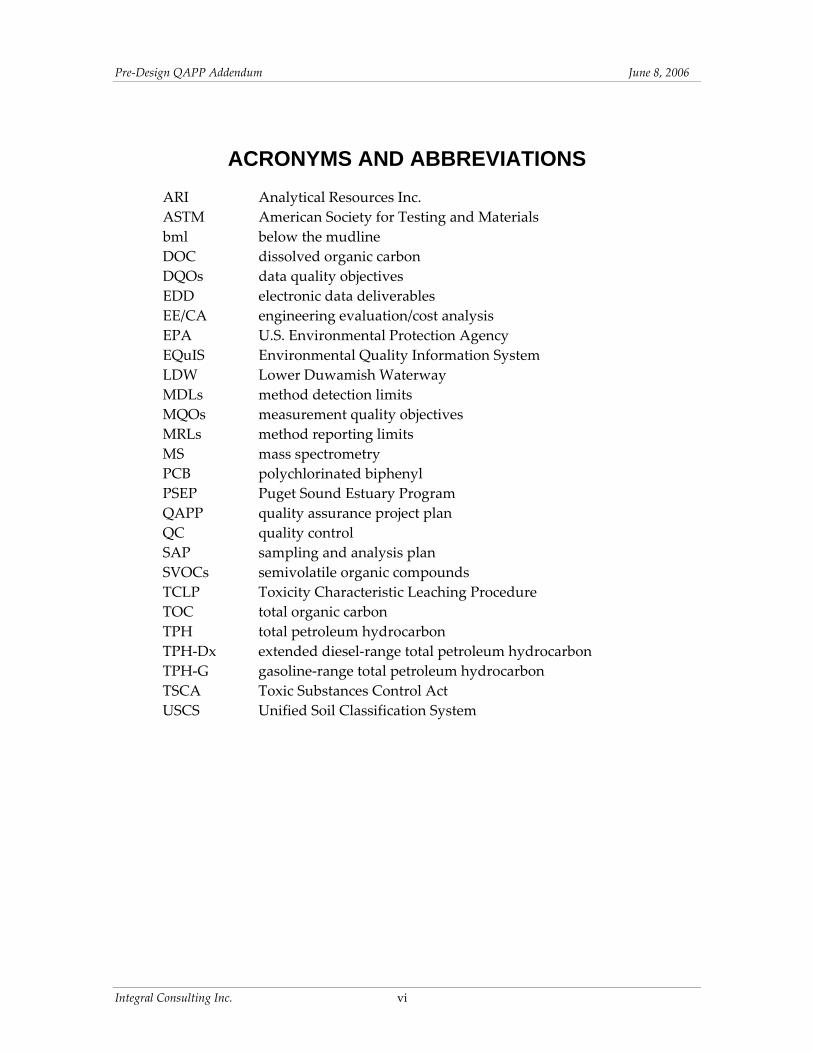
Pre‐Design QAPP Addendum June 8 2006
completed by an independent validation firm which will be selected at a later date The validation firm will also complete data verification (ie verifying that analytical procedures and calculations were completed correctly and checking transcriptions of the laboratory data) for the first data package for each analysis as part of the full validation that will be completed for these packages
The results of the Pre‐Design SAP Addendum field sampling will be presented in the 60 Design Documents for the Slip 4 Early Action currently scheduled for completion in fall 2006
The start date for field sampling will be determined following EPA approval of the project SAP and QAPP addenda and pending property access permission from property owners Currently it is anticipated that field sampling will begin in June 2006 The field and reporting schedules are discussed further in Sections 32 and 44 respectively of the Pre‐Design SAP Addendum
A7 QUALITY OBJECTIVES AND CRITERIA FOR MEASUREMENT DATA
Data quality objectives (DQOs) for the pre‐design investigation are described in Section A7 of the Boundary Definition QAPP Target method reporting limits (MRLs) and method detection limits (MDLs) for this project are summarized in Table A6‐2 Measurement quality objectives (MQOs) for this project are summarized in Table A7‐1 Analyte concentrations for this project will be reported to the MDL as described in the Boundary Definition QAPP
Integral Consulting Inc 3
Pre‐Design QAPP Addendum June 8 2006
This page intentionally left blank
Integral Consulting Inc 4
Pre‐Design QAPP Addendum June 8 2006
SECTION B DATA GENERATION AND ACQUISITION
B1 SAMPLING PROCESS DESIGN
This section supplements Section B1 of the Boundary Definition QAPP The sampling effort for this study will include the collection of seep water surface sediment subsurface sediment and subsurface bank soil from Slip 4 in the LDW
Seep water will be collected as discrete samples from individual seep locations (to be determined in the field) Water quality parameters (conductivity turbidity temperature dissolved oxygen pH salinity and oxidation‐reduction potential) will be measured in the field at each seep and in adjacent surface water prior to sample collection Seep samples will be filtered in the field through 10‐μm glass filters and submitted for laboratory analysis for polychlorinated biphenyl (PCB) Aroclors and dissolved organic carbon (DOC)
Surface sediment samples will be collected from the 0ndash10 cm interval at four locations and will be analyzed for total organic carbon (TOC) and PCB Aroclors
All subsurface soil samples will be characterized according to the Unified Soil Classification System (USCS) as per current annual American Society for Testing and Materials (ASTM) Methods This visualmanual classification will occur in the field per ASTM D2488 and will be recorded on boring logs except where undisturbed samples for geotechnical characterization are submitted to the laboratory For those samples the laboratory will perform the USCS classification following ASTM D2487 Field USCS classification is not considered an ldquoanalysisrdquo in the QAPP
Sediment cores from 0 to 5 ft below the mudline (bml) will be collected from seven locations to characterize sediment in the area to be dredged Chemical analyses will be required on six samples as follows
bull One composite sample representing the entire 0‐ to 5‐ft lengths of cores from three of the locations will be submitted for chemical analysis to evaluate whether the material will require disposal as a Washington State Dangerous Waste Analysis of this sample will include PCB Aroclors chlorinated pesticides semivolatile organic compounds (SVOCs) metals extended diesel‐range total petroleum hydrocarbons (TPH‐Dx) gasoline‐range TPH (TPH‐G) and TOC An additional aliquot of this sample will be archived for potential future Toxicity Characteristic Leaching Procedure (TCLP) analyses for SVOCs chlorinated pesticides and metals
Integral Consulting Inc 5
Pre‐Design QAPP Addendum June 8 2006
bull Five samples representing the 0‐ to 5‐ft lengths of five discrete cores near the head of the slip will be submitted for PCB Aroclor analysis to determine if segregation of an area potentially requiring disposal under the Toxic Substances Control Act (TSCA) regulations is practicable
The cores will also be subsampled into three sample intervals (0ndash2 ft bml 2ndash4 ft bml and 4ndash5 ft bml) These discrete samples will be analyzed for geotechnical parameters as follows
bull Nine subsamples from three cores (SC12 SC13 and SC16) representing the area to be dredged will be analyzed for grain‐size distribution water content specific gravity Atterberg limits and TOC One of the cores in this group (SC16) is located in the potential TSCA area
bull Three archived samples from SC01 (0ndash2 ft 2ndash4 ft and 4ndash6 ft) collected in 2004 will be analyzed for grain‐size distribution water content USCS classification specific gravity Atterberg limits and TOC
Samples of bank soil from bank removal areas are needed to characterize the material for disposal Two composite samples will be collected using hand auger boring or hand dug test pit one sample from Zone 2 and one sample from Zones 3 4 and 5 These samples will be submitted for chemical and geotechnical analyses Chemical analytes will include PCB Aroclors chlorinated pesticides SVOCs metals TPH‐Dx TPH‐G TOC and TCLP analysis for SVOCs chlorinated pesticides and metals Samples collected for TCLP analysis of SVOCs metals and chlorinated pesticides will be archived at the laboratory and analysis will be contingent on the results of dry‐weight analysis TCLP analysis will only need to be performed when the TCLP contaminants in the results from the total analysis are greater than or equal to 20 times the maximum concentration for toxicity characteristic regulatory levels (set forth in Table 1 of 40 CFR 26124) The ldquo20 times rulerdquo is allowable because of the sample dilution that is a component of the TCLP Method 1311 (Section 12 of this method) as is clarified in EPA 540‐R‐94‐005a Geotechnical analyses will include grain‐size distribution water content specific gravity Atterberg limits and TOC
Sediment samples from four cores will be collected for geotechnical analyses to determine the consolidation properties strength and bearing capacity of the underlying sediments These samples will be analyzed by consolidation testing unconsolidated undrained (UU) triaxial shear grain‐size distribution USCS classification water content bulk density specific gravity Atterberg limits and TOC
Field quality control (QC) samples will be collected for chemical analysis as specified in the QAPP (Integral 2004a) with the exception that field duplicate cores will not be
Integral Consulting Inc 6
Pre‐Design QAPP Addendum June 8 2006
collected Field QC samples are described in Section 36 of the Boundary Definition SAP (Integral 2004b) and Section 34 of the Pre‐Design SAP Addendum (Integral 2006b)
B2 SAMPLING METHODS
This section supplements Section B2 of the Boundary Definition QAPP
Seep samples will be collected using either a funnel or peristaltic pump with attached dedicated disposal tubing Intertidal surface sediment will be collected using stainless‐steel bowls and spoons Subsurface sediment cores for dredge area characterization and for geotechnical evaluation will be collected using Shelby tubes and split‐spoon samplers advanced through hollow‐stem augers using a barge‐mounted drill rig Subsurface bank soil samples will be collected using hand augers or hand‐dug test pits Sampling methods are described in Section 33 of the Pre‐Design SAP Addendum Requirements for sample containers storage temperature and holding times for sediment and seep water samples are summarized in Table B2‐1 of this Pre‐Design QAPP Addendum
B3 SAMPLE HANDLING AND CUSTODY
Sample handling and custody procedures will be completed as described in Section 334 of the Pre‐Design SAP Addendum (Integral 2006b)
B4 ANALYTICAL METHODS
Analyses will be completed according to the methods provided in Table A6‐2 These methods will be modified in some cases as described in the Boundary Definition QAPP Sediment samples will be analyzed for SVOCs by full‐scan mass spectrometry (MS) Selected ion monitoring will not be used because the sensitivity of full‐scan MS is sufficient to meet the study objectives
B5 QUALITY CONTROL
Quality control samples will be prepared in the field and at the laboratories to monitor the bias and precision of the sample collection and analysis procedures Field quality control samples are described below Laboratory quality control will be completed as described in the Boundary Definition QAPP
B51 Field Quality Control Samples
Field QC samples for the pre‐design investigation will include field duplicates (for surface sediment sampling) field replicates (for seep sampling) and equipment rinse blanks (for
Integral Consulting Inc 7
Pre‐Design QAPP Addendum June 8 2006
seep and surface sediment sampling) Field QC samples will be collected at a minimum for seep and surface sediment samples at a frequency of 5 percent of the sample total The procedures for preparing field replicates duplicates and rinse blanks are presented in Section 36 of the Boundary Definition SAP (Integral 2004b) and Section 34 of the Pre‐Design SAP Addendum (Integral 2006b) Validation criteria and procedures for field QC samples are described in Sections D1 and D2 of the Boundary Definition QAPP (Integral 2004a)
Integral Consulting Inc 8
Pre‐Design QAPP Addendum June 8 2006
REFERENCES
ASTM 2003 Annual Book of ASTM Standards Volume 0408 American Society for Testing and Materials Philadelphia PA
Integral 2004a Lower Duwamish Waterway Slip 4 Early Action Area Quality Assurance Project Plan for Boundary Definition Prepared for Seattle City Light and King County Seattle WA Integral Consulting Inc Mercer Island WA
Integral 2004b Lower Duwamish Waterway Slip 4 Early Action Area Sampling and Analysis Plan for Boundary Definition Prepared for City of Seattle and King County WA Integral Consulting Inc Mercer Island WA
Integral 2006a Lower Duwamish Waterway Slip 4 Early Action Area Engineering EvaluationCost Analysis Submitted to US EPA Region 10 City of Seattle King County Seattle WA Integral Consulting Inc Mercer Island WA
Integral 2006b Lower Duwamish Waterway Slip 4 Early Action Area Sampling and Analysis Plan for Boundary Definition Addendum Pre‐Design Investigation Sampling Prepared for Seattle City Light and King County Seattle WA Integral Consulting Inc Mercer Island WA
Plumb Jr RH 1981 Procedures for Handling and Chemical Analysis of Sediment and Water Samples Technical Report EPACE‐81‐1 Prepared by Great Lakes Laboratory State University College at Buffalo Buffalo NY for the US Environmental Protection AgencyUS Army Corps of Engineers Technical Committee on Criteria for Dredged and Fill Material Published by the US Army Engineer Waterways Experiment Station CE Vicksburg MS
PSEP 1986 Puget Sound Estuary Program Recommended Protocols for Measuring Conventional Sediment Variables in Puget Sound Final Report TC‐3991‐04 Prepared for US Environmental Protection Agency Region 10 Seattle WA Tetra Tech and HRA Inc Bellevue WA (minor corrections April 2003)
PSEP 1997a Puget Sound Estuary Program Recommended Guidelines for Measuring Organic Compounds in Puget Sound Water Sediment and Tissue Samples In Recommended Protocols for Measuring Selected Environmental Variables in Puget Sound Puget Sound Action Team Olympia WA
Integral Consulting Inc 9
Pre‐Design QAPP Addendum June 8 2006
PSEP 1997b Puget Sound Estuary Program Recommended Quality Assurance and Quality Control Guidelines for the Collection of Environmental Data in Puget Sound In Recommended Protocols for Measuring Selected Environmental Variables in Puget Sound Puget Sound Action Team Olympia WA
USEPA 2003 SW‐846 On‐line Test Methods for Evaluating Solid Waste ‐PhysicalChemical Methods US Environmental Protection Agency httpwwwepagovepaoswerhazwastetestmainhtm Accessed January 8 2004
Windward 2004 Data Report Survey and Sampling of Lower Duwamish Waterway Seeps Prepared for Lower Duwamish Waterway Group for submittal to US Environmental Protection Agency and Washington State Department of Ecology Windward Environmental LLC Seattle WA
Integral Consulting Inc 10
FIGURE
EPA Region 10
Remedial Project Manager Karen Keeley
Principal In Charge Betsy Day
Project Manager Dave Schuchardt
Integral Laboratory Coordinator
amp QA Manager Maja Tritt
EPA QA Manger Ginna Grepo-Grove
Project QA Coordinator Ried Carscadden
Data Management Tom Schulz
Field Coordinator Jane Sund or Susan FitzGerald
City of Seattle
Project Coordinator Jennie Goldberg
Data Validation Firm
to be determined
Analytical Resources Inc
Project Manager Sue Dunnihoo
Cascade Drilling
Figure A4-1 Organization Chart
TABLES
Slip 4 Pre‐Design QAPP Addendum June 8 2006
Table A4-1 Project Team Contact Information
Organization EPA Region 10
Individual Karen Keeley Ginna Grepo-Grove
Project Role Project Coordinator QA Manager
Phone 206-553-2141 206-553-1632
Fax 206-553-0124 206-553-8210
Email KeeleyKarenepagov Grepo-GroveGinaepagov
City of Seattle Jennie Goldberg SCL Project Coordinator 206-684-3167 206-386-4589 jenniegoldbergseattlegov
Integral Consulting Betsy Day David Schuchardt Reid Carscadden Jane Sund or Susan FitzGerald Ian Stupakoff
Principal in Charge Project Manager Project QA Coordinator
Field Coordinator
Field Staff
206-957-0346 206-957-0350 206-957-0343 503-284-5545 ext15 or 206-957-0352 360-705-3534 360-259-2518
206-230-9601 206-230-9601 206-230-9601 503-284-5755 or 206-230-9601
360-705-3669
bdayintegral-corpcom dschuchardtintegral-corpcom rcarscaddenintegral-corpcom jsundintegral-corpcom sfitzgeraldintegral-corpcom istupakoffintegral-corpcom
Maja Tritt Tom Schulz
Laboratory CoordinatorQA Manager Data Manager
206-957-0353 360-705-3534 ext17
206-230-9601 360-705-3669
mtrittintegral-corpcom tschulzintegral-corpcom
Analytical Resources Inc (ARI)
Sue Dunnihoo Dave Mitchell
Laboratory Project Manager Laboratory QA Manager
206-695-6207 206-695-6205
206-621-7523 206-621-7523
suedarilabscom davemarilabscom
Integral Consulting Inc 1 of 1
Slip 4 Pre‐Design QAPP Addendum June 8 2006
Table A6-1 Estimated Numbers of Pre-Design Samples by Sample Type
Total Number Number of Field Field Equipment of Field
Sample Type and Analysis Samples1 Duplicates2 Replicates2 Rinse Blanks Samples
Seep WaterPCB Aroclors 4ndash6 0 1 1 6ndash8 DOC 4ndash6 0 1 1 6ndash8
Surface Sediment PCB Aroclors 4 1 0 1 6 Total Organic Carbon 4 1 0 NA 5
Subsurface Sediment PCB Aroclors 6 0 0 0 6 SVOCs 1 0 0 0 1 Metals 1 0 0 0 1 Chlorinated Pesticides 1 0 0 0 1 TPH-Dx 1 0 0 0 1 TPH-G 1 0 0 0 1 TCLP SVOCs 3 1 0 0 NA 1 TCLP Metals 3 1 0 0 NA 1 TCLP Chlorinated Pesticides 3 1 0 0 NA 1 Grain-Size Distribution 20 0 0 NA 20 Total Organic Carbon 20 0 0 NA 20 Water Content 20 0 0 NA 20 Bulk Density 8 0 0 NA 8 Specific Gravity 20 0 0 NA 20 Atterberg limits 20 0 0 NA 20 USCS Classification 4 11 0 0 NA 11 Consolidation 8 NA 0 NA 8 UU Triaxial Shear 8 NA 0 NA 8
Subsurface Sediment (Archived Analysis) Grain-Size Distribution 3 0 0 NA 3 Total Organic Carbon 3 0 0 NA 3 Water Content 3 0 0 NA 3 Bulk Density 0 0 0 NA 0 Specific Gravity 3 0 0 NA 3 Atterberg Limits 3 0 0 NA 3 USCS Classification 4 3 0 0 NA 3
Subsurface Bank Soil PCB Aroclors 2 0 0 0 2 SVOCs 2 0 0 0 2 Metals 2 0 0 0 2 Chlorinated Pesticides 2 0 0 0 2 TPH-Dx 2 0 0 0 2 TPH-G 2 0 0 0 2 TCLP SVOCs 3 2 0 0 NA 2 TCLP Metals 3 2 0 0 NA 2 TCLP Chlorinated Pesticides 3 2 0 0 NA 2 Grain-Size Distribution 2 0 0 NA 2
Integral Consulting Inc 1 of 2
Slip 4 Pre‐Design QAPP Addendum June 8 2006
Table A6-1 Estimated Numbers of Pre-Design Samples by Sample Type
Total Number Number of Field Field Equipment of Field
Sample Type and Analysis Samples1 Duplicates2 Replicates2 Rinse Blanks Samples
Total Organic Carbon 2 0 0 NA 2 Water Content 2 0 0 NA 2 Bulk Density 0 0 0 NA 0 Specific Gravity 2 0 0 NA 2 Atterberg Limits 2 0 0 NA 2
Notes DOC = dissolved organic carbon PCB = polychlorinated biphenyls SVOCs = semivolatile organic compounds TCLP = Toxicity Characteristic Leaching Procedure TPH-Dx = total petroleum hydrocarbons diesel- and oil-range1 Numbers are based on the Pre-Design SAP Addendum Integral 2006b Table 2-12 Duplicate replicate and rinsate samples will not be collected for waste disposal characterization samples 3 TCLP samples will be archived for potential future analysis 4 Only laboratory USCS Classification samples by ASTM D2487 are shown
Integral Consulting Inc 2 of 2
Slip 4 Pre‐Design QAPP Addendum June 8 2006
Table A6-2 Target Analytes Methods and Method Reporting Limits for Pre-Design Investigation Samples
Analyte Sample Preparation Method Sample Cleanup Method1 Analysis Method MDL MRL
Seep Water PCB Aroclors (ugL)
Dissolved Organic Carbon (mgL)
ARI Low Level (Modified EPA 3510)
EPA 4151
EPA 3660B (sulfur) EPA 3665A (acid)
EPA 3630C (silica gel) optional2
--
GCECD (EPA 8082)3
Direct combustion (EPA 4151)
0005
0018
001
002
Sediments and Bank Soils Conventional analytes
USCS Classification -- -- ASTM D-2487 -- --Grain Size ( dry wt) TOC ( dry wt)
----
----
PSEP (1986) Plumb (1981)
--0018
01 002
Geotechnical Charactersitics Atterberg limits ( moisture) Specific gravity (gcc) Water content (percent) Bulk density (gcc) Consolidation
----------
----------
ASTM D-4318 ASTM D-854
ASTM D-2216 ASTM D-2937
ASTM D-2435 Method B
----------
01 001 01 01 --
UU Triaxial Shear -- -- ASTM D-2850 -- --
PCB Aroclors (ugkg dry weight) ARI Low Level (EPA 3550B-mod) EPA 3660B (sulfur) optional2
EPA 3665A (acid) optional2 GCECD (EPA 8082)3 04 40
Pesticides (ugkg dry weight) 44rsquo-DDT 44rsquo-DDE 44rsquo-DDD 24rsquo-DDT 24rsquo-DDE 24rsquo-DDD Aldrin alpha-BHC beta-BHC delta-BHC gamma-BHC Oxychlordane alpha-chlordane gamma-chlordane cis-nonachlor
Sonication (EPA 3550B) Sonication (EPA 3550B) Sonication (EPA 3550B) Sonication (EPA 3550B) Sonication (EPA 3550B) Sonication (EPA 3550B) Sonication (EPA 3550B) Sonication (EPA 3550B) Sonication (EPA 3550B) Sonication (EPA 3550B) Sonication (EPA 3550B) Sonication (EPA 3550B) Sonication (EPA 3550B) Sonication (EPA 3550B) Sonication (EPA 3550B)
EPA 3660BEPA3630C EPA 3660BEPA3630C EPA 3660BEPA3630C EPA 3660BEPA3630C EPA 3660BEPA3630C EPA 3660BEPA3630C EPA 3660BEPA3630C EPA 3660BEPA3630C EPA 3660BEPA3630C EPA 3660BEPA3630C EPA 3660BEPA3630C EPA 3660BEPA3630C EPA 3660BEPA3630C EPA 3660BEPA3630C EPA 3660BEPA3630C
EPA 8081A EPA 8081A EPA 8081A EPA 8081A EPA 8081A EPA 8081A EPA 8081A EPA 8081A EPA 8081A EPA 8081A EPA 8081A EPA 8081A EPA 8081A EPA 8081A EPA 8081A
0199 0125 0095 0091 0033 0037 0044 0051 0091 0021 009
0123 0058 012 055
20 20 20 20 20 20 10 10 10 10 10 20 10 10 20
Integral Consulting Inc 1 of 4
Slip 4 Pre‐Design QAPP Addendum June 8 2006
Table A6-2 Target Analytes Methods and Method Reporting Limits for Pre-Design Investigation Samples
Analyte Sample Preparation Method Sample Cleanup Method1 Analysis Method MDL MRL
trans-nonachlor Sonication (EPA 3550B) EPA 3660BEPA3630C EPA 8081A 0024 20 Dieldrin Sonication (EPA 3550B) EPA 3660BEPA3630C EPA 8081A 0085 20 Endosulfan Sonication (EPA 3550B) EPA 3660BEPA3630C EPA 8081A 0063 10 Endosulfan II Sonication (EPA 3550B) EPA 3660BEPA3630C EPA 8081A 0125 20 Endosulfan sulfate Sonication (EPA 3550B) EPA 3660BEPA3630C EPA 8081A 0148 20 Endrin Sonication (EPA 3550B) EPA 3660BEPA3630C EPA 8081A 0082 20 Endrin aldehyde Sonication (EPA 3550B) EPA 3660BEPA3630C EPA 8081A 0184 20 Heptachlor Sonication (EPA 3550B) EPA 3660BEPA3630C EPA 8081A 0073 10 Heptachlor epoxide Sonication (EPA 3550B) EPA 3660BEPA3630C EPA 8081A 0054 10 Hexachlorobenzene Sonication (EPA 3550B) EPA 3660BEPA3630C EPA 8081A 0066 10 Methoxychlor Sonication (EPA 3550B) EPA 3660BEPA3630C EPA 8081A 112 100 Mirex Sonication (EPA 3550B) EPA 3660BEPA3630C EPA 8081A 0013 20 Toxaphene Sonication (EPA 3550B) EPA 3660BEPA3630C EPA 8081A 296 1000
Metals (mgkg) Arsenic EPA 3050 -- EPA 6010B 078 50 Cadmium EPA 3050 -- EPA 6010B 004 02 Chromium EPA 3050 -- EPA 6010B 009 05 Copper EPA 3050 -- EPA 6010B 006 02 Lead EPA 3050 -- EPA 6010B 011 20 Mercury EPA 7471A -- EPA 7471A 0003 005 Silver EPA 3050 -- EPA 6010B 004 03 Zinc EPA 3050 -- EPA 6010B 034 06
Semivolatiles (mgkg) 124-Trichlorobenzene EPA 3550B EPA 3640A EPA 8270C - PSEP (Full scan) 953 20 12-Dichlorobenzene EPA 3550B EPA 3640A EPA 8270C - PSEP (Full scan) 115 20 13-Dichlorobenzene EPA 3550B EPA 3640A EPA 8270C - PSEP (Full scan) 84 20 14-Dichlorobenzene EPA 3550B EPA 3640A EPA 8270C - PSEP (Full scan) 103 20 24-Dimethylphenol EPA 3550B EPA 3640A EPA 8270C - PSEP (Full scan) 63 20 2-Methylnaphthalene EPA 3550B EPA 3640A EPA 8270C - PSEP (Full scan) 183 20 2-Methylphenol EPA 3550B EPA 3640A EPA 8270C - PSEP (Full scan) 679 20 4-Methylphenol EPA 3550B EPA 3640A EPA 8270C - PSEP (Full scan) 73 20 Acenapthene EPA 3550B EPA 3640A EPA 8270C - PSEP (Full scan) 104 20 Acenapththylene EPA 3550B EPA 3640A EPA 8270C - PSEP (Full scan) 938 20 Anthracene EPA 3550B EPA 3640A EPA 8270C - PSEP (Full scan) 795 20 Benz[a]anthracene EPA 3550B EPA 3640A EPA 8270C - PSEP (Full scan) 867 20 Benzo[a]pyrene EPA 3550B EPA 3640A EPA 8270C - PSEP (Full scan) 805 20
Integral Consulting Inc 2 of 4
Slip 4 Pre‐Design QAPP Addendum June 8 2006
Table A6-2 Target Analytes Methods and Method Reporting Limits for Pre-Design Investigation Samples
Analyte Sample Preparation Method Sample Cleanup Method1 Analysis Method MDL MRL
Benzo[b+j+k]fluoranthene EPA 3550B EPA 3640A EPA 8270C - PSEP (Full scan) 863 20 Benzo[ghi]perylene EPA 3550B EPA 3640A EPA 8270C - PSEP (Full scan) 85 20 Benzoic acid EPA 3550B EPA 3640A EPA 8270C - PSEP (Full scan) 89 200 Benzyl alcohol EPA 3550B EPA 3640A EPA 8270C - PSEP (Full scan) 147 20 Bis[2-ethylhexyl]phthalate EPA 3550B EPA 3640A EPA 8270C - PSEP (Full scan) 11 20 Butyl benzyl phthalate EPA 3550B EPA 3640A EPA 8270C - PSEP (Full scan) 91 20 Chrysene EPA 3550B EPA 3640A EPA 8270C - PSEP (Full scan) 97 20 Dibenz[ah]anthracene EPA 3550B EPA 3640A EPA 8270C - PSEP (Full scan) 85 20 Dibenzofuran EPA 3550B EPA 3640A EPA 8270C - PSEP (Full scan) 17 20 Diethyl phthalate EPA 3550B EPA 3640A EPA 8270C - PSEP (Full scan) 106 20 Dimethyl phthalate EPA 3550B EPA 3640A EPA 8270C - PSEP (Full scan) 94 20 Di-n-butyl phthalate EPA 3550B EPA 3640A EPA 8270C - PSEP (Full scan) 66 20 Di-n-octyl phthalate EPA 3550B EPA 3640A EPA 8270C - PSEP (Full scan) 101 20 Fluoranthene EPA 3550B EPA 3640A EPA 8270C - PSEP (Full scan) 86 20 Fluorene EPA 3550B EPA 3640A EPA 8270C - PSEP (Full scan) 116 20 Hexachlorobenzene EPA 3550B EPA 3640A EPA 8270C - PSEP (Full scan) 104 20 Hexachlorobutadiene EPA 3550B EPA 3640A EPA 8270C - PSEP (Full scan) 92 20 Hexachloroethane EPA 3550B EPA 3640A EPA 8270C - PSEP (Full scan) 97 20 Indeno[123-cd]pyrene EPA 3550B EPA 3640A EPA 8270C - PSEP (Full scan) 62 20 Naphthalene EPA 3550B EPA 3640A EPA 8270C - PSEP (Full scan) 117 20 N -nitrosodiphenylamine EPA 3550B EPA 3640A EPA 8270C - PSEP (Full scan) 87 20 Pentachlorophenol EPA 3550B EPA 3640A EPA 8270C - PSEP (Full scan) 473 100 Phenanthrene EPA 3550B EPA 3640A EPA 8270C - PSEP (Full scan) 103 20 Phenol EPA 3550B EPA 3640A EPA 8270C - PSEP (Full scan) 122 20 Pyrene EPA 3550B EPA 3640A EPA 8270C - PSEP (Full scan) 94 20
Total Petroleum Hydrocarbons (mgkg dry weight) Diesel-Range Hydrocarbons NWTPH-Dx EPA 3550B NWTPH-Dx 094 50 Oil-Range Hydrocarbons EPA 3630C silica gel (as needed) 211 100 Gasoline-range hydrocarbons NWTPH-G Methanol extraction NWTPH-G 318 50
Purge and trap
TCLP Metals (mgL) Arsenic EPA 1311 -- EPA 6010B 059 50 Barium EPA 1311 -- EPA 6010B 002 02 Cadmium EPA 1311 -- EPA 6010B 011 05 Chromium EPA 1311 -- EPA 6010B 004 02 Lead EPA 1311 -- EPA 6010B 006 20
Integral Consulting Inc 3 of 4
Slip 4 Pre‐Design QAPP Addendum June 8 2006
Table A6-2 Target Analytes Methods and Method Reporting Limits for Pre-Design Investigation Samples
Analyte Sample Preparation Method Sample Cleanup Method1 Analysis Method MDL MRL
Mercury EPA 1311 -- EPA 7471A 00004 01 Selenium EPA 1311 -- EPA 6010B 004 03 Silver EPA 1311 -- EPA 6010B 017 06
TCLP Semivolatiles (mgL) 14-Dichlorobenzene EPA 1311 followed by EPA 3510C -- EPA 8270C (15) 000217 0005 245-Trichlorophenol EPA 1311 followed by EPA 3510C -- EPA 8270C (15) 000115 0025 246-Trichlorophenol EPA 1311 followed by EPA 3510C -- EPA 8270C (15) 00013 0025 24-Dinitrotoluene EPA 1311 followed by EPA 3510C -- EPA 8270C (15) 000157 0025 Hexachlorobenzene EPA 1311 followed by EPA 3510C -- EPA 8270C (15) 000214 0005 Hexachlorobutadiene EPA 1311 followed by EPA 3510C -- EPA 8270C (15) 00027 0005 Hexachloroethane EPA 1311 followed by EPA 3510C -- EPA 8270C (15) 0002025 0005 Nitrobenzene EPA 1311 followed by EPA 3510C -- EPA 8270C (15) 000243 0005 o -Cresol EPA 1311 followed by EPA 3510C -- EPA 8270C (15) 0000915 0005 p -Cresol and m -Cresol (coelute) EPA 1311 followed by EPA 3510C -- EPA 8270C (15) 0001505 0005 Total cresol (summed from above) -- -- -- -- 0010 Pentachlorophenol EPA 1311 followed by EPA 3510C -- EPA 8270C (15) 00061 0005 Pyridine EPA 1311 followed by EPA 3510C -- EPA 8270C (15) -- 0025
TCLP Pesticides (mgL) Chlordane EPA 1311 followed by EPA 3510C EPA 3630CEPA3630C EPA 8081A (110) 00001 00005 Endrin EPA 1311 followed by EPA 3510C EPA 3630CEPA3630C EPA 8081A (110) 000022 0001 Heptachlor EPA 1311 followed by EPA 3510C EPA 3630CEPA3630C EPA 8081A (110) 000009 00005 Heptachlor epoxide EPA 1311 followed by EPA 3510C EPA 3630CEPA3630C EPA 8081A (110) 000015 00005 Lindane EPA 1311 followed by EPA 3510C EPA 3630CEPA3630C EPA 8081A (110) 000014 00005 Methoxychlor EPA 1311 followed by EPA 3510C EPA 3630CEPA3630C EPA 8081A (110) 000097 0005 Toxaphene EPA 1311 followed by EPA 3510C EPA 3630CEPA3630C EPA 8081A (110) -- 01
1 Gel permeation chromatography is required for organics analyses under PSEP Additional cleanups will be used as required to meet MRLs 2 The need for cleanup to be based on screens and the color of extracts (Windward 2004) 3 If more than one Aroclor is detected in a sample the laboratory will choose unique peaks to quantitate each individual Aroclor (ie a peak can only be used in the quantitation of one Aroclor Windward 2004)
Integral Consulting Inc 4 of 4
Slip 4 Pre‐Design QAPP Addendum June 8 2006
Table A7-1 Measurement Quality Objectives Bias Precision Completeness
Analysis (percent) (RPD) (percent) Conventional Analytes
Grain Size ( dry weight) -- plusmn20 95 TOC ( dry weight) 75-125 plusmn30 95
Inorganic Compounds Metals 75-125 plusmn35 95 TCLP Metals -- plusmn35 95
Organic Compounds Pesticides 50-150 plusmn50 95 PCB Aroclors 50-150 plusmn50 95 Semivolatile organic compounds 50-150 plusmn50 95 Total petroleum hydrocarbons 50-150 plusmn50 95 TCLP Semivolatile organic compounds 50-150 plusmn50 95 TCLP Pesticides 50-150 plusmn50 95
Notes RPD = relative percent difference PCB = polychlorinated biphenyl TCLP = Toxicity Characterization Leaching Procedure TOC = total organic carbon
Integral Consulting Inc 1 of 1
Slip 4 Pre‐Design QAPP Addendum June 8 2006
Table B2-1 Sample Containers Preservation Holding Times and Sample Volume
ApproximateContainer Laboratory
Analysis1 Type2 Container Size Subsample Preservation Holding Time
Sediment Samples for Chemical and Geotechnical Testing on Disturbed Samples 34
TOC WMG 2 oz 2 g 4plusmn2ordmC 14 days Grain size WMG 16 oz 100 g 4plusmn2ordmC 6 months Atterberg Limits and Specific Gravity WMG 16 oz 225 g 4plusmn2ordmC 6 months Pesticides WMG 8 oz 25 g 4plusmn2ordmC 14 days40 days5
Diesel- and Oil-Range Hydrocarbons WMG 8 oz 20 g 4plusmn2ordmC 14 days40 days5
Gasoline-Range Hydrocarbons WMG 2 oz 5 g No headspace 14 days 4plusmn2ordmC
(do not freeze) SVOCs WMG 8 oz 50 g 4plusmn2ordmC 14 days40 days5
Metals WMG 8 oz 10 g 4plusmn2ordmC 6 months6
TCLP Metals (includes mercury) WMG 8 oz 100 g 4plusmn2ordmC 6 months6
TCLP SVOCs WMG 8 oz 100 g 4plusmn2ordmC 14 days TCLP Pesticides WMG 8 oz 100 g 4plusmn2ordmC 14 days
Undisturbed Sediment Samples for Geotechnical Analysis
Bulk Density Shelby tube -- -- 4plusmn2ordmC --Consolidation Shelby tube -- -- 4plusmn2ordmC --UU Triaxial Shear Shelby tube -- -- 4plusmn2ordmC --
Seep Water and Equipment Rinse Blanks for Chemical Analysis
Dissolved Organic Carbon7 AG 250 mL 250 mL H2SO4 to pHlt2 28 days cool 4degC
PCB Aroclors7 AG Two - 1000 mL 1000 mL 4plusmn2ordmC 7 days40 days8
Notes AG = Amber glass HDPE = high density polyethylene -- = not applicable WMG = wide mouth glass jar TCLP = Toxicity Characterization Leaching Procedure 1 The laboratory may modify sample jar sizes or analyte groupings 2 Teflonreg-lined lids will be used for glass sample containers Some samples may be combined with other analytes 3 Undisturbed core segments contained in capped Shelby tubes will be submitted for some geotechnical analyses 4 Geotechnical analysis also conducted on archived sediment cores 5 Holding time is 14 days to extraction and extracts must be analyzed within 40 days from extraction 6 Holding time for mercury is 28 days 7 Rinsates submitted for seep sample equipment (DOC and PCB analyses) will be field filtered through 10-microm glass filters 8 Holding time is 7 days to extraction and extracts must be analyzed within 40 days from extraction
Integral Consulting Inc 1 of 1
APPENDIX D
FORMS
CHAIN OF CUSTODYLABORATORY ANALYSIS REQUEST FORM
Page of Turn Around Requested
Report to Phone Analyses Requested NotesComments
Company Fax
Address Proj Name
City Proj Number
State Sampler
Zipcode
Sample ID Sample
Date Sample
Time Sample Matrix
No Con-tainers
Relinquished Received by Special InstructionsNotes
(Signature) (Signature)
Printed name Printed name
Company Company Number of Coolers
Cooler Temp(s)
Date Time Date Time COC Seals Intact
Bottles Intact
Integral Consulting Inc Core Description and Sample Information
STATION PROJECT___________________________ REPLICATE
Field Log by Processing by Coring by Tide Level from MLLW Depth to Mudline Mudline Elev
Date Time
Total Drive Length Recovered Length Recovery Efficiency
Note All elevations depths and distances in feet Core Description - Core Tube Lengths In-Situ Summary Log
Tube Length
Sample No Visual Description
Photo Number
Interpreted Summary
Sample No Acquisition Notes
_1
_2
_3
_4
_5
_6
_7
_8
_9
_10
_11
_12
_13
_14
_15
_16
_17
_18
_1
_2
_3
_4
_5
_6
_7
_8
_9
_10
_11
_12
_13
_14
_15
_16
_17
_18
Core Tube Field Cut Information Sample Test Information Notes
Sample No
Tube Length Interval
Segment Length Sample NoTests
In-Situ Depth
Int
FIELD CHANGE REQUEST Project Number
Project Number Project Name
Field Change No Page to
CHANGE REQUEST Applicable Reference Description of Change
Reason for Change
Impact on Present and Completed Work
(Field Scientist)
(Field Task Leader)
Requested by Date
Acknowledged by Date
FIELD OPERATIONS MANAGER RECOMMENDATION
Recommended Disposition
(Sampling and Analysis Coordinator)
Recommendation by Date
PROJECT MANAGER APPROVAL
Final Deposition
(CERCLA Coordinator)
ApprovedDisapprove d by Date
CORRECTIVE ACTION RECORD
Page of
Audit Report No Date
Report Originator
Person Responsible for Response
DESCRIPTION OF PROBLEM
Date and Time Problem Recognized By
Date of Actual Occurrence By
Analyte Analytical Method
Cause of Problem
CORRECTIVE ACTION PLANNED
Person Responsible for Corrective Action
Date of Corrective Action
Corrective Action Plan Approval Date
DESCRIPTION OF FOLLOW-UP ACTIVITIES
Person Responsible for Follow-up Activities
Date of Follow-up Activity
Final Corrective Action Approval Date
SURFACE SEDIMENTSOIL COLLECTION FORM Project Name Project No Page
Date Crew
Weather
Sampling Method
Time Station Replicate Acceptable grab F Yes F No
Bottom Depth Penetration Depth RPD Depth Analyses before homogenization F VOC F Sulfides F Other Sample ID Type F cobble F gravel F sand C M F F silt clay F organic matter F woodshell fragments Color F drab olive F gray F black F brown F brown surface Odor F none F slight F moderate F strong F sulfidic F petroleum F other Comments
Time Station Replicate Acceptable grab F Yes F No
Bottom Depth Penetration Depth RPD Depth Analyses before homogenization F VOC F Sulfides F Other Sample ID Type F cobble F gravel F sand C M F F silt clay F organic matter F woodshell fragments Color F drab olive F gray F black F brown F brown surface Odor F none F slight F moderate F strong F sulfidic F petroleum F other Comments
Time Station Replicate Acceptable grab F Yes F No
Bottom Depth Penetration Depth RPD Depth Analyses before homogenization F VOC F Sulfides F Other Sample ID Type F cobble F gravel F sand C M F F silt clay F organic matter F woodshell fragments Color F drab olive F gray F black F brown F brown surface Odor F none F slight F moderate F strong F sulfidic F petroleum F other Comments
Time Station Replicate Acceptable grab F Yes F No
Bottom Depth Penetration Depth RPD Depth Analyses before homogenization F VOC F Sulfides F Other Sample ID Type F cobble F gravel F sand C M F F silt clay F organic matter F woodshell fragments Color F drab olive F gray F black F brown F brown surface Odor F none F slight F moderate F strong F sulfidic F petroleum F other Comments
WATER SAMPLE COLLECTION FORM
Station ID _______________________ Project Name
Sample No _____________________ Project Number
Date______________ Collector
Field Parameters
pH Temperature Conductivity Turbidity Comments
__________ __________ __________ ________ __________________________
Sampling Device
Filter None
Sample Containers Collection Time___________
Tag No Container Type Preservative Analytical Method QA Remarks
Comments
Sample Location Sketch
Samplersrsquo Signature______________________________ Date ________________
- SAP - Appendix_c_qapp_06pdf
-
- Figure_A4-1_Org-Chartpdf
-
- Page 1
-
Pre‐Design QAPP Addendum June 8 2006
This page intentionally left blank
Integral Consulting Inc 4
Pre‐Design QAPP Addendum June 8 2006
SECTION B DATA GENERATION AND ACQUISITION
B1 SAMPLING PROCESS DESIGN
This section supplements Section B1 of the Boundary Definition QAPP The sampling effort for this study will include the collection of seep water surface sediment subsurface sediment and subsurface bank soil from Slip 4 in the LDW
Seep water will be collected as discrete samples from individual seep locations (to be determined in the field) Water quality parameters (conductivity turbidity temperature dissolved oxygen pH salinity and oxidation‐reduction potential) will be measured in the field at each seep and in adjacent surface water prior to sample collection Seep samples will be filtered in the field through 10‐μm glass filters and submitted for laboratory analysis for polychlorinated biphenyl (PCB) Aroclors and dissolved organic carbon (DOC)
Surface sediment samples will be collected from the 0ndash10 cm interval at four locations and will be analyzed for total organic carbon (TOC) and PCB Aroclors
All subsurface soil samples will be characterized according to the Unified Soil Classification System (USCS) as per current annual American Society for Testing and Materials (ASTM) Methods This visualmanual classification will occur in the field per ASTM D2488 and will be recorded on boring logs except where undisturbed samples for geotechnical characterization are submitted to the laboratory For those samples the laboratory will perform the USCS classification following ASTM D2487 Field USCS classification is not considered an ldquoanalysisrdquo in the QAPP
Sediment cores from 0 to 5 ft below the mudline (bml) will be collected from seven locations to characterize sediment in the area to be dredged Chemical analyses will be required on six samples as follows
bull One composite sample representing the entire 0‐ to 5‐ft lengths of cores from three of the locations will be submitted for chemical analysis to evaluate whether the material will require disposal as a Washington State Dangerous Waste Analysis of this sample will include PCB Aroclors chlorinated pesticides semivolatile organic compounds (SVOCs) metals extended diesel‐range total petroleum hydrocarbons (TPH‐Dx) gasoline‐range TPH (TPH‐G) and TOC An additional aliquot of this sample will be archived for potential future Toxicity Characteristic Leaching Procedure (TCLP) analyses for SVOCs chlorinated pesticides and metals
Integral Consulting Inc 5
Pre‐Design QAPP Addendum June 8 2006
bull Five samples representing the 0‐ to 5‐ft lengths of five discrete cores near the head of the slip will be submitted for PCB Aroclor analysis to determine if segregation of an area potentially requiring disposal under the Toxic Substances Control Act (TSCA) regulations is practicable
The cores will also be subsampled into three sample intervals (0ndash2 ft bml 2ndash4 ft bml and 4ndash5 ft bml) These discrete samples will be analyzed for geotechnical parameters as follows
bull Nine subsamples from three cores (SC12 SC13 and SC16) representing the area to be dredged will be analyzed for grain‐size distribution water content specific gravity Atterberg limits and TOC One of the cores in this group (SC16) is located in the potential TSCA area
bull Three archived samples from SC01 (0ndash2 ft 2ndash4 ft and 4ndash6 ft) collected in 2004 will be analyzed for grain‐size distribution water content USCS classification specific gravity Atterberg limits and TOC
Samples of bank soil from bank removal areas are needed to characterize the material for disposal Two composite samples will be collected using hand auger boring or hand dug test pit one sample from Zone 2 and one sample from Zones 3 4 and 5 These samples will be submitted for chemical and geotechnical analyses Chemical analytes will include PCB Aroclors chlorinated pesticides SVOCs metals TPH‐Dx TPH‐G TOC and TCLP analysis for SVOCs chlorinated pesticides and metals Samples collected for TCLP analysis of SVOCs metals and chlorinated pesticides will be archived at the laboratory and analysis will be contingent on the results of dry‐weight analysis TCLP analysis will only need to be performed when the TCLP contaminants in the results from the total analysis are greater than or equal to 20 times the maximum concentration for toxicity characteristic regulatory levels (set forth in Table 1 of 40 CFR 26124) The ldquo20 times rulerdquo is allowable because of the sample dilution that is a component of the TCLP Method 1311 (Section 12 of this method) as is clarified in EPA 540‐R‐94‐005a Geotechnical analyses will include grain‐size distribution water content specific gravity Atterberg limits and TOC
Sediment samples from four cores will be collected for geotechnical analyses to determine the consolidation properties strength and bearing capacity of the underlying sediments These samples will be analyzed by consolidation testing unconsolidated undrained (UU) triaxial shear grain‐size distribution USCS classification water content bulk density specific gravity Atterberg limits and TOC
Field quality control (QC) samples will be collected for chemical analysis as specified in the QAPP (Integral 2004a) with the exception that field duplicate cores will not be
Integral Consulting Inc 6
Pre‐Design QAPP Addendum June 8 2006
collected Field QC samples are described in Section 36 of the Boundary Definition SAP (Integral 2004b) and Section 34 of the Pre‐Design SAP Addendum (Integral 2006b)
B2 SAMPLING METHODS
This section supplements Section B2 of the Boundary Definition QAPP
Seep samples will be collected using either a funnel or peristaltic pump with attached dedicated disposal tubing Intertidal surface sediment will be collected using stainless‐steel bowls and spoons Subsurface sediment cores for dredge area characterization and for geotechnical evaluation will be collected using Shelby tubes and split‐spoon samplers advanced through hollow‐stem augers using a barge‐mounted drill rig Subsurface bank soil samples will be collected using hand augers or hand‐dug test pits Sampling methods are described in Section 33 of the Pre‐Design SAP Addendum Requirements for sample containers storage temperature and holding times for sediment and seep water samples are summarized in Table B2‐1 of this Pre‐Design QAPP Addendum
B3 SAMPLE HANDLING AND CUSTODY
Sample handling and custody procedures will be completed as described in Section 334 of the Pre‐Design SAP Addendum (Integral 2006b)
B4 ANALYTICAL METHODS
Analyses will be completed according to the methods provided in Table A6‐2 These methods will be modified in some cases as described in the Boundary Definition QAPP Sediment samples will be analyzed for SVOCs by full‐scan mass spectrometry (MS) Selected ion monitoring will not be used because the sensitivity of full‐scan MS is sufficient to meet the study objectives
B5 QUALITY CONTROL
Quality control samples will be prepared in the field and at the laboratories to monitor the bias and precision of the sample collection and analysis procedures Field quality control samples are described below Laboratory quality control will be completed as described in the Boundary Definition QAPP
B51 Field Quality Control Samples
Field QC samples for the pre‐design investigation will include field duplicates (for surface sediment sampling) field replicates (for seep sampling) and equipment rinse blanks (for
Integral Consulting Inc 7
Pre‐Design QAPP Addendum June 8 2006
seep and surface sediment sampling) Field QC samples will be collected at a minimum for seep and surface sediment samples at a frequency of 5 percent of the sample total The procedures for preparing field replicates duplicates and rinse blanks are presented in Section 36 of the Boundary Definition SAP (Integral 2004b) and Section 34 of the Pre‐Design SAP Addendum (Integral 2006b) Validation criteria and procedures for field QC samples are described in Sections D1 and D2 of the Boundary Definition QAPP (Integral 2004a)
Integral Consulting Inc 8
Pre‐Design QAPP Addendum June 8 2006
REFERENCES
ASTM 2003 Annual Book of ASTM Standards Volume 0408 American Society for Testing and Materials Philadelphia PA
Integral 2004a Lower Duwamish Waterway Slip 4 Early Action Area Quality Assurance Project Plan for Boundary Definition Prepared for Seattle City Light and King County Seattle WA Integral Consulting Inc Mercer Island WA
Integral 2004b Lower Duwamish Waterway Slip 4 Early Action Area Sampling and Analysis Plan for Boundary Definition Prepared for City of Seattle and King County WA Integral Consulting Inc Mercer Island WA
Integral 2006a Lower Duwamish Waterway Slip 4 Early Action Area Engineering EvaluationCost Analysis Submitted to US EPA Region 10 City of Seattle King County Seattle WA Integral Consulting Inc Mercer Island WA
Integral 2006b Lower Duwamish Waterway Slip 4 Early Action Area Sampling and Analysis Plan for Boundary Definition Addendum Pre‐Design Investigation Sampling Prepared for Seattle City Light and King County Seattle WA Integral Consulting Inc Mercer Island WA
Plumb Jr RH 1981 Procedures for Handling and Chemical Analysis of Sediment and Water Samples Technical Report EPACE‐81‐1 Prepared by Great Lakes Laboratory State University College at Buffalo Buffalo NY for the US Environmental Protection AgencyUS Army Corps of Engineers Technical Committee on Criteria for Dredged and Fill Material Published by the US Army Engineer Waterways Experiment Station CE Vicksburg MS
PSEP 1986 Puget Sound Estuary Program Recommended Protocols for Measuring Conventional Sediment Variables in Puget Sound Final Report TC‐3991‐04 Prepared for US Environmental Protection Agency Region 10 Seattle WA Tetra Tech and HRA Inc Bellevue WA (minor corrections April 2003)
PSEP 1997a Puget Sound Estuary Program Recommended Guidelines for Measuring Organic Compounds in Puget Sound Water Sediment and Tissue Samples In Recommended Protocols for Measuring Selected Environmental Variables in Puget Sound Puget Sound Action Team Olympia WA
Integral Consulting Inc 9
Pre‐Design QAPP Addendum June 8 2006
PSEP 1997b Puget Sound Estuary Program Recommended Quality Assurance and Quality Control Guidelines for the Collection of Environmental Data in Puget Sound In Recommended Protocols for Measuring Selected Environmental Variables in Puget Sound Puget Sound Action Team Olympia WA
USEPA 2003 SW‐846 On‐line Test Methods for Evaluating Solid Waste ‐PhysicalChemical Methods US Environmental Protection Agency httpwwwepagovepaoswerhazwastetestmainhtm Accessed January 8 2004
Windward 2004 Data Report Survey and Sampling of Lower Duwamish Waterway Seeps Prepared for Lower Duwamish Waterway Group for submittal to US Environmental Protection Agency and Washington State Department of Ecology Windward Environmental LLC Seattle WA
Integral Consulting Inc 10
FIGURE
EPA Region 10
Remedial Project Manager Karen Keeley
Principal In Charge Betsy Day
Project Manager Dave Schuchardt
Integral Laboratory Coordinator
amp QA Manager Maja Tritt
EPA QA Manger Ginna Grepo-Grove
Project QA Coordinator Ried Carscadden
Data Management Tom Schulz
Field Coordinator Jane Sund or Susan FitzGerald
City of Seattle
Project Coordinator Jennie Goldberg
Data Validation Firm
to be determined
Analytical Resources Inc
Project Manager Sue Dunnihoo
Cascade Drilling
Figure A4-1 Organization Chart
TABLES
Slip 4 Pre‐Design QAPP Addendum June 8 2006
Table A4-1 Project Team Contact Information
Organization EPA Region 10
Individual Karen Keeley Ginna Grepo-Grove
Project Role Project Coordinator QA Manager
Phone 206-553-2141 206-553-1632
Fax 206-553-0124 206-553-8210
Email KeeleyKarenepagov Grepo-GroveGinaepagov
City of Seattle Jennie Goldberg SCL Project Coordinator 206-684-3167 206-386-4589 jenniegoldbergseattlegov
Integral Consulting Betsy Day David Schuchardt Reid Carscadden Jane Sund or Susan FitzGerald Ian Stupakoff
Principal in Charge Project Manager Project QA Coordinator
Field Coordinator
Field Staff
206-957-0346 206-957-0350 206-957-0343 503-284-5545 ext15 or 206-957-0352 360-705-3534 360-259-2518
206-230-9601 206-230-9601 206-230-9601 503-284-5755 or 206-230-9601
360-705-3669
bdayintegral-corpcom dschuchardtintegral-corpcom rcarscaddenintegral-corpcom jsundintegral-corpcom sfitzgeraldintegral-corpcom istupakoffintegral-corpcom
Maja Tritt Tom Schulz
Laboratory CoordinatorQA Manager Data Manager
206-957-0353 360-705-3534 ext17
206-230-9601 360-705-3669
mtrittintegral-corpcom tschulzintegral-corpcom
Analytical Resources Inc (ARI)
Sue Dunnihoo Dave Mitchell
Laboratory Project Manager Laboratory QA Manager
206-695-6207 206-695-6205
206-621-7523 206-621-7523
suedarilabscom davemarilabscom
Integral Consulting Inc 1 of 1
Slip 4 Pre‐Design QAPP Addendum June 8 2006
Table A6-1 Estimated Numbers of Pre-Design Samples by Sample Type
Total Number Number of Field Field Equipment of Field
Sample Type and Analysis Samples1 Duplicates2 Replicates2 Rinse Blanks Samples
Seep WaterPCB Aroclors 4ndash6 0 1 1 6ndash8 DOC 4ndash6 0 1 1 6ndash8
Surface Sediment PCB Aroclors 4 1 0 1 6 Total Organic Carbon 4 1 0 NA 5
Subsurface Sediment PCB Aroclors 6 0 0 0 6 SVOCs 1 0 0 0 1 Metals 1 0 0 0 1 Chlorinated Pesticides 1 0 0 0 1 TPH-Dx 1 0 0 0 1 TPH-G 1 0 0 0 1 TCLP SVOCs 3 1 0 0 NA 1 TCLP Metals 3 1 0 0 NA 1 TCLP Chlorinated Pesticides 3 1 0 0 NA 1 Grain-Size Distribution 20 0 0 NA 20 Total Organic Carbon 20 0 0 NA 20 Water Content 20 0 0 NA 20 Bulk Density 8 0 0 NA 8 Specific Gravity 20 0 0 NA 20 Atterberg limits 20 0 0 NA 20 USCS Classification 4 11 0 0 NA 11 Consolidation 8 NA 0 NA 8 UU Triaxial Shear 8 NA 0 NA 8
Subsurface Sediment (Archived Analysis) Grain-Size Distribution 3 0 0 NA 3 Total Organic Carbon 3 0 0 NA 3 Water Content 3 0 0 NA 3 Bulk Density 0 0 0 NA 0 Specific Gravity 3 0 0 NA 3 Atterberg Limits 3 0 0 NA 3 USCS Classification 4 3 0 0 NA 3
Subsurface Bank Soil PCB Aroclors 2 0 0 0 2 SVOCs 2 0 0 0 2 Metals 2 0 0 0 2 Chlorinated Pesticides 2 0 0 0 2 TPH-Dx 2 0 0 0 2 TPH-G 2 0 0 0 2 TCLP SVOCs 3 2 0 0 NA 2 TCLP Metals 3 2 0 0 NA 2 TCLP Chlorinated Pesticides 3 2 0 0 NA 2 Grain-Size Distribution 2 0 0 NA 2
Integral Consulting Inc 1 of 2
Slip 4 Pre‐Design QAPP Addendum June 8 2006
Table A6-1 Estimated Numbers of Pre-Design Samples by Sample Type
Total Number Number of Field Field Equipment of Field
Sample Type and Analysis Samples1 Duplicates2 Replicates2 Rinse Blanks Samples
Total Organic Carbon 2 0 0 NA 2 Water Content 2 0 0 NA 2 Bulk Density 0 0 0 NA 0 Specific Gravity 2 0 0 NA 2 Atterberg Limits 2 0 0 NA 2
Notes DOC = dissolved organic carbon PCB = polychlorinated biphenyls SVOCs = semivolatile organic compounds TCLP = Toxicity Characteristic Leaching Procedure TPH-Dx = total petroleum hydrocarbons diesel- and oil-range1 Numbers are based on the Pre-Design SAP Addendum Integral 2006b Table 2-12 Duplicate replicate and rinsate samples will not be collected for waste disposal characterization samples 3 TCLP samples will be archived for potential future analysis 4 Only laboratory USCS Classification samples by ASTM D2487 are shown
Integral Consulting Inc 2 of 2
Slip 4 Pre‐Design QAPP Addendum June 8 2006
Table A6-2 Target Analytes Methods and Method Reporting Limits for Pre-Design Investigation Samples
Analyte Sample Preparation Method Sample Cleanup Method1 Analysis Method MDL MRL
Seep Water PCB Aroclors (ugL)
Dissolved Organic Carbon (mgL)
ARI Low Level (Modified EPA 3510)
EPA 4151
EPA 3660B (sulfur) EPA 3665A (acid)
EPA 3630C (silica gel) optional2
--
GCECD (EPA 8082)3
Direct combustion (EPA 4151)
0005
0018
001
002
Sediments and Bank Soils Conventional analytes
USCS Classification -- -- ASTM D-2487 -- --Grain Size ( dry wt) TOC ( dry wt)
----
----
PSEP (1986) Plumb (1981)
--0018
01 002
Geotechnical Charactersitics Atterberg limits ( moisture) Specific gravity (gcc) Water content (percent) Bulk density (gcc) Consolidation
----------
----------
ASTM D-4318 ASTM D-854
ASTM D-2216 ASTM D-2937
ASTM D-2435 Method B
----------
01 001 01 01 --
UU Triaxial Shear -- -- ASTM D-2850 -- --
PCB Aroclors (ugkg dry weight) ARI Low Level (EPA 3550B-mod) EPA 3660B (sulfur) optional2
EPA 3665A (acid) optional2 GCECD (EPA 8082)3 04 40
Pesticides (ugkg dry weight) 44rsquo-DDT 44rsquo-DDE 44rsquo-DDD 24rsquo-DDT 24rsquo-DDE 24rsquo-DDD Aldrin alpha-BHC beta-BHC delta-BHC gamma-BHC Oxychlordane alpha-chlordane gamma-chlordane cis-nonachlor
Sonication (EPA 3550B) Sonication (EPA 3550B) Sonication (EPA 3550B) Sonication (EPA 3550B) Sonication (EPA 3550B) Sonication (EPA 3550B) Sonication (EPA 3550B) Sonication (EPA 3550B) Sonication (EPA 3550B) Sonication (EPA 3550B) Sonication (EPA 3550B) Sonication (EPA 3550B) Sonication (EPA 3550B) Sonication (EPA 3550B) Sonication (EPA 3550B)
EPA 3660BEPA3630C EPA 3660BEPA3630C EPA 3660BEPA3630C EPA 3660BEPA3630C EPA 3660BEPA3630C EPA 3660BEPA3630C EPA 3660BEPA3630C EPA 3660BEPA3630C EPA 3660BEPA3630C EPA 3660BEPA3630C EPA 3660BEPA3630C EPA 3660BEPA3630C EPA 3660BEPA3630C EPA 3660BEPA3630C EPA 3660BEPA3630C
EPA 8081A EPA 8081A EPA 8081A EPA 8081A EPA 8081A EPA 8081A EPA 8081A EPA 8081A EPA 8081A EPA 8081A EPA 8081A EPA 8081A EPA 8081A EPA 8081A EPA 8081A
0199 0125 0095 0091 0033 0037 0044 0051 0091 0021 009
0123 0058 012 055
20 20 20 20 20 20 10 10 10 10 10 20 10 10 20
Integral Consulting Inc 1 of 4
Slip 4 Pre‐Design QAPP Addendum June 8 2006
Table A6-2 Target Analytes Methods and Method Reporting Limits for Pre-Design Investigation Samples
Analyte Sample Preparation Method Sample Cleanup Method1 Analysis Method MDL MRL
trans-nonachlor Sonication (EPA 3550B) EPA 3660BEPA3630C EPA 8081A 0024 20 Dieldrin Sonication (EPA 3550B) EPA 3660BEPA3630C EPA 8081A 0085 20 Endosulfan Sonication (EPA 3550B) EPA 3660BEPA3630C EPA 8081A 0063 10 Endosulfan II Sonication (EPA 3550B) EPA 3660BEPA3630C EPA 8081A 0125 20 Endosulfan sulfate Sonication (EPA 3550B) EPA 3660BEPA3630C EPA 8081A 0148 20 Endrin Sonication (EPA 3550B) EPA 3660BEPA3630C EPA 8081A 0082 20 Endrin aldehyde Sonication (EPA 3550B) EPA 3660BEPA3630C EPA 8081A 0184 20 Heptachlor Sonication (EPA 3550B) EPA 3660BEPA3630C EPA 8081A 0073 10 Heptachlor epoxide Sonication (EPA 3550B) EPA 3660BEPA3630C EPA 8081A 0054 10 Hexachlorobenzene Sonication (EPA 3550B) EPA 3660BEPA3630C EPA 8081A 0066 10 Methoxychlor Sonication (EPA 3550B) EPA 3660BEPA3630C EPA 8081A 112 100 Mirex Sonication (EPA 3550B) EPA 3660BEPA3630C EPA 8081A 0013 20 Toxaphene Sonication (EPA 3550B) EPA 3660BEPA3630C EPA 8081A 296 1000
Metals (mgkg) Arsenic EPA 3050 -- EPA 6010B 078 50 Cadmium EPA 3050 -- EPA 6010B 004 02 Chromium EPA 3050 -- EPA 6010B 009 05 Copper EPA 3050 -- EPA 6010B 006 02 Lead EPA 3050 -- EPA 6010B 011 20 Mercury EPA 7471A -- EPA 7471A 0003 005 Silver EPA 3050 -- EPA 6010B 004 03 Zinc EPA 3050 -- EPA 6010B 034 06
Semivolatiles (mgkg) 124-Trichlorobenzene EPA 3550B EPA 3640A EPA 8270C - PSEP (Full scan) 953 20 12-Dichlorobenzene EPA 3550B EPA 3640A EPA 8270C - PSEP (Full scan) 115 20 13-Dichlorobenzene EPA 3550B EPA 3640A EPA 8270C - PSEP (Full scan) 84 20 14-Dichlorobenzene EPA 3550B EPA 3640A EPA 8270C - PSEP (Full scan) 103 20 24-Dimethylphenol EPA 3550B EPA 3640A EPA 8270C - PSEP (Full scan) 63 20 2-Methylnaphthalene EPA 3550B EPA 3640A EPA 8270C - PSEP (Full scan) 183 20 2-Methylphenol EPA 3550B EPA 3640A EPA 8270C - PSEP (Full scan) 679 20 4-Methylphenol EPA 3550B EPA 3640A EPA 8270C - PSEP (Full scan) 73 20 Acenapthene EPA 3550B EPA 3640A EPA 8270C - PSEP (Full scan) 104 20 Acenapththylene EPA 3550B EPA 3640A EPA 8270C - PSEP (Full scan) 938 20 Anthracene EPA 3550B EPA 3640A EPA 8270C - PSEP (Full scan) 795 20 Benz[a]anthracene EPA 3550B EPA 3640A EPA 8270C - PSEP (Full scan) 867 20 Benzo[a]pyrene EPA 3550B EPA 3640A EPA 8270C - PSEP (Full scan) 805 20
Integral Consulting Inc 2 of 4
Slip 4 Pre‐Design QAPP Addendum June 8 2006
Table A6-2 Target Analytes Methods and Method Reporting Limits for Pre-Design Investigation Samples
Analyte Sample Preparation Method Sample Cleanup Method1 Analysis Method MDL MRL
Benzo[b+j+k]fluoranthene EPA 3550B EPA 3640A EPA 8270C - PSEP (Full scan) 863 20 Benzo[ghi]perylene EPA 3550B EPA 3640A EPA 8270C - PSEP (Full scan) 85 20 Benzoic acid EPA 3550B EPA 3640A EPA 8270C - PSEP (Full scan) 89 200 Benzyl alcohol EPA 3550B EPA 3640A EPA 8270C - PSEP (Full scan) 147 20 Bis[2-ethylhexyl]phthalate EPA 3550B EPA 3640A EPA 8270C - PSEP (Full scan) 11 20 Butyl benzyl phthalate EPA 3550B EPA 3640A EPA 8270C - PSEP (Full scan) 91 20 Chrysene EPA 3550B EPA 3640A EPA 8270C - PSEP (Full scan) 97 20 Dibenz[ah]anthracene EPA 3550B EPA 3640A EPA 8270C - PSEP (Full scan) 85 20 Dibenzofuran EPA 3550B EPA 3640A EPA 8270C - PSEP (Full scan) 17 20 Diethyl phthalate EPA 3550B EPA 3640A EPA 8270C - PSEP (Full scan) 106 20 Dimethyl phthalate EPA 3550B EPA 3640A EPA 8270C - PSEP (Full scan) 94 20 Di-n-butyl phthalate EPA 3550B EPA 3640A EPA 8270C - PSEP (Full scan) 66 20 Di-n-octyl phthalate EPA 3550B EPA 3640A EPA 8270C - PSEP (Full scan) 101 20 Fluoranthene EPA 3550B EPA 3640A EPA 8270C - PSEP (Full scan) 86 20 Fluorene EPA 3550B EPA 3640A EPA 8270C - PSEP (Full scan) 116 20 Hexachlorobenzene EPA 3550B EPA 3640A EPA 8270C - PSEP (Full scan) 104 20 Hexachlorobutadiene EPA 3550B EPA 3640A EPA 8270C - PSEP (Full scan) 92 20 Hexachloroethane EPA 3550B EPA 3640A EPA 8270C - PSEP (Full scan) 97 20 Indeno[123-cd]pyrene EPA 3550B EPA 3640A EPA 8270C - PSEP (Full scan) 62 20 Naphthalene EPA 3550B EPA 3640A EPA 8270C - PSEP (Full scan) 117 20 N -nitrosodiphenylamine EPA 3550B EPA 3640A EPA 8270C - PSEP (Full scan) 87 20 Pentachlorophenol EPA 3550B EPA 3640A EPA 8270C - PSEP (Full scan) 473 100 Phenanthrene EPA 3550B EPA 3640A EPA 8270C - PSEP (Full scan) 103 20 Phenol EPA 3550B EPA 3640A EPA 8270C - PSEP (Full scan) 122 20 Pyrene EPA 3550B EPA 3640A EPA 8270C - PSEP (Full scan) 94 20
Total Petroleum Hydrocarbons (mgkg dry weight) Diesel-Range Hydrocarbons NWTPH-Dx EPA 3550B NWTPH-Dx 094 50 Oil-Range Hydrocarbons EPA 3630C silica gel (as needed) 211 100 Gasoline-range hydrocarbons NWTPH-G Methanol extraction NWTPH-G 318 50
Purge and trap
TCLP Metals (mgL) Arsenic EPA 1311 -- EPA 6010B 059 50 Barium EPA 1311 -- EPA 6010B 002 02 Cadmium EPA 1311 -- EPA 6010B 011 05 Chromium EPA 1311 -- EPA 6010B 004 02 Lead EPA 1311 -- EPA 6010B 006 20
Integral Consulting Inc 3 of 4
Slip 4 Pre‐Design QAPP Addendum June 8 2006
Table A6-2 Target Analytes Methods and Method Reporting Limits for Pre-Design Investigation Samples
Analyte Sample Preparation Method Sample Cleanup Method1 Analysis Method MDL MRL
Mercury EPA 1311 -- EPA 7471A 00004 01 Selenium EPA 1311 -- EPA 6010B 004 03 Silver EPA 1311 -- EPA 6010B 017 06
TCLP Semivolatiles (mgL) 14-Dichlorobenzene EPA 1311 followed by EPA 3510C -- EPA 8270C (15) 000217 0005 245-Trichlorophenol EPA 1311 followed by EPA 3510C -- EPA 8270C (15) 000115 0025 246-Trichlorophenol EPA 1311 followed by EPA 3510C -- EPA 8270C (15) 00013 0025 24-Dinitrotoluene EPA 1311 followed by EPA 3510C -- EPA 8270C (15) 000157 0025 Hexachlorobenzene EPA 1311 followed by EPA 3510C -- EPA 8270C (15) 000214 0005 Hexachlorobutadiene EPA 1311 followed by EPA 3510C -- EPA 8270C (15) 00027 0005 Hexachloroethane EPA 1311 followed by EPA 3510C -- EPA 8270C (15) 0002025 0005 Nitrobenzene EPA 1311 followed by EPA 3510C -- EPA 8270C (15) 000243 0005 o -Cresol EPA 1311 followed by EPA 3510C -- EPA 8270C (15) 0000915 0005 p -Cresol and m -Cresol (coelute) EPA 1311 followed by EPA 3510C -- EPA 8270C (15) 0001505 0005 Total cresol (summed from above) -- -- -- -- 0010 Pentachlorophenol EPA 1311 followed by EPA 3510C -- EPA 8270C (15) 00061 0005 Pyridine EPA 1311 followed by EPA 3510C -- EPA 8270C (15) -- 0025
TCLP Pesticides (mgL) Chlordane EPA 1311 followed by EPA 3510C EPA 3630CEPA3630C EPA 8081A (110) 00001 00005 Endrin EPA 1311 followed by EPA 3510C EPA 3630CEPA3630C EPA 8081A (110) 000022 0001 Heptachlor EPA 1311 followed by EPA 3510C EPA 3630CEPA3630C EPA 8081A (110) 000009 00005 Heptachlor epoxide EPA 1311 followed by EPA 3510C EPA 3630CEPA3630C EPA 8081A (110) 000015 00005 Lindane EPA 1311 followed by EPA 3510C EPA 3630CEPA3630C EPA 8081A (110) 000014 00005 Methoxychlor EPA 1311 followed by EPA 3510C EPA 3630CEPA3630C EPA 8081A (110) 000097 0005 Toxaphene EPA 1311 followed by EPA 3510C EPA 3630CEPA3630C EPA 8081A (110) -- 01
1 Gel permeation chromatography is required for organics analyses under PSEP Additional cleanups will be used as required to meet MRLs 2 The need for cleanup to be based on screens and the color of extracts (Windward 2004) 3 If more than one Aroclor is detected in a sample the laboratory will choose unique peaks to quantitate each individual Aroclor (ie a peak can only be used in the quantitation of one Aroclor Windward 2004)
Integral Consulting Inc 4 of 4
Slip 4 Pre‐Design QAPP Addendum June 8 2006
Table A7-1 Measurement Quality Objectives Bias Precision Completeness
Analysis (percent) (RPD) (percent) Conventional Analytes
Grain Size ( dry weight) -- plusmn20 95 TOC ( dry weight) 75-125 plusmn30 95
Inorganic Compounds Metals 75-125 plusmn35 95 TCLP Metals -- plusmn35 95
Organic Compounds Pesticides 50-150 plusmn50 95 PCB Aroclors 50-150 plusmn50 95 Semivolatile organic compounds 50-150 plusmn50 95 Total petroleum hydrocarbons 50-150 plusmn50 95 TCLP Semivolatile organic compounds 50-150 plusmn50 95 TCLP Pesticides 50-150 plusmn50 95
Notes RPD = relative percent difference PCB = polychlorinated biphenyl TCLP = Toxicity Characterization Leaching Procedure TOC = total organic carbon
Integral Consulting Inc 1 of 1
Slip 4 Pre‐Design QAPP Addendum June 8 2006
Table B2-1 Sample Containers Preservation Holding Times and Sample Volume
ApproximateContainer Laboratory
Analysis1 Type2 Container Size Subsample Preservation Holding Time
Sediment Samples for Chemical and Geotechnical Testing on Disturbed Samples 34
TOC WMG 2 oz 2 g 4plusmn2ordmC 14 days Grain size WMG 16 oz 100 g 4plusmn2ordmC 6 months Atterberg Limits and Specific Gravity WMG 16 oz 225 g 4plusmn2ordmC 6 months Pesticides WMG 8 oz 25 g 4plusmn2ordmC 14 days40 days5
Diesel- and Oil-Range Hydrocarbons WMG 8 oz 20 g 4plusmn2ordmC 14 days40 days5
Gasoline-Range Hydrocarbons WMG 2 oz 5 g No headspace 14 days 4plusmn2ordmC
(do not freeze) SVOCs WMG 8 oz 50 g 4plusmn2ordmC 14 days40 days5
Metals WMG 8 oz 10 g 4plusmn2ordmC 6 months6
TCLP Metals (includes mercury) WMG 8 oz 100 g 4plusmn2ordmC 6 months6
TCLP SVOCs WMG 8 oz 100 g 4plusmn2ordmC 14 days TCLP Pesticides WMG 8 oz 100 g 4plusmn2ordmC 14 days
Undisturbed Sediment Samples for Geotechnical Analysis
Bulk Density Shelby tube -- -- 4plusmn2ordmC --Consolidation Shelby tube -- -- 4plusmn2ordmC --UU Triaxial Shear Shelby tube -- -- 4plusmn2ordmC --
Seep Water and Equipment Rinse Blanks for Chemical Analysis
Dissolved Organic Carbon7 AG 250 mL 250 mL H2SO4 to pHlt2 28 days cool 4degC
PCB Aroclors7 AG Two - 1000 mL 1000 mL 4plusmn2ordmC 7 days40 days8
Notes AG = Amber glass HDPE = high density polyethylene -- = not applicable WMG = wide mouth glass jar TCLP = Toxicity Characterization Leaching Procedure 1 The laboratory may modify sample jar sizes or analyte groupings 2 Teflonreg-lined lids will be used for glass sample containers Some samples may be combined with other analytes 3 Undisturbed core segments contained in capped Shelby tubes will be submitted for some geotechnical analyses 4 Geotechnical analysis also conducted on archived sediment cores 5 Holding time is 14 days to extraction and extracts must be analyzed within 40 days from extraction 6 Holding time for mercury is 28 days 7 Rinsates submitted for seep sample equipment (DOC and PCB analyses) will be field filtered through 10-microm glass filters 8 Holding time is 7 days to extraction and extracts must be analyzed within 40 days from extraction
Integral Consulting Inc 1 of 1
APPENDIX D
FORMS
CHAIN OF CUSTODYLABORATORY ANALYSIS REQUEST FORM
Page of Turn Around Requested
Report to Phone Analyses Requested NotesComments
Company Fax
Address Proj Name
City Proj Number
State Sampler
Zipcode
Sample ID Sample
Date Sample
Time Sample Matrix
No Con-tainers
Relinquished Received by Special InstructionsNotes
(Signature) (Signature)
Printed name Printed name
Company Company Number of Coolers
Cooler Temp(s)
Date Time Date Time COC Seals Intact
Bottles Intact
Integral Consulting Inc Core Description and Sample Information
STATION PROJECT___________________________ REPLICATE
Field Log by Processing by Coring by Tide Level from MLLW Depth to Mudline Mudline Elev
Date Time
Total Drive Length Recovered Length Recovery Efficiency
Note All elevations depths and distances in feet Core Description - Core Tube Lengths In-Situ Summary Log
Tube Length
Sample No Visual Description
Photo Number
Interpreted Summary
Sample No Acquisition Notes
_1
_2
_3
_4
_5
_6
_7
_8
_9
_10
_11
_12
_13
_14
_15
_16
_17
_18
_1
_2
_3
_4
_5
_6
_7
_8
_9
_10
_11
_12
_13
_14
_15
_16
_17
_18
Core Tube Field Cut Information Sample Test Information Notes
Sample No
Tube Length Interval
Segment Length Sample NoTests
In-Situ Depth
Int
FIELD CHANGE REQUEST Project Number
Project Number Project Name
Field Change No Page to
CHANGE REQUEST Applicable Reference Description of Change
Reason for Change
Impact on Present and Completed Work
(Field Scientist)
(Field Task Leader)
Requested by Date
Acknowledged by Date
FIELD OPERATIONS MANAGER RECOMMENDATION
Recommended Disposition
(Sampling and Analysis Coordinator)
Recommendation by Date
PROJECT MANAGER APPROVAL
Final Deposition
(CERCLA Coordinator)
ApprovedDisapprove d by Date
CORRECTIVE ACTION RECORD
Page of
Audit Report No Date
Report Originator
Person Responsible for Response
DESCRIPTION OF PROBLEM
Date and Time Problem Recognized By
Date of Actual Occurrence By
Analyte Analytical Method
Cause of Problem
CORRECTIVE ACTION PLANNED
Person Responsible for Corrective Action
Date of Corrective Action
Corrective Action Plan Approval Date
DESCRIPTION OF FOLLOW-UP ACTIVITIES
Person Responsible for Follow-up Activities
Date of Follow-up Activity
Final Corrective Action Approval Date
SURFACE SEDIMENTSOIL COLLECTION FORM Project Name Project No Page
Date Crew
Weather
Sampling Method
Time Station Replicate Acceptable grab F Yes F No
Bottom Depth Penetration Depth RPD Depth Analyses before homogenization F VOC F Sulfides F Other Sample ID Type F cobble F gravel F sand C M F F silt clay F organic matter F woodshell fragments Color F drab olive F gray F black F brown F brown surface Odor F none F slight F moderate F strong F sulfidic F petroleum F other Comments
Time Station Replicate Acceptable grab F Yes F No
Bottom Depth Penetration Depth RPD Depth Analyses before homogenization F VOC F Sulfides F Other Sample ID Type F cobble F gravel F sand C M F F silt clay F organic matter F woodshell fragments Color F drab olive F gray F black F brown F brown surface Odor F none F slight F moderate F strong F sulfidic F petroleum F other Comments
Time Station Replicate Acceptable grab F Yes F No
Bottom Depth Penetration Depth RPD Depth Analyses before homogenization F VOC F Sulfides F Other Sample ID Type F cobble F gravel F sand C M F F silt clay F organic matter F woodshell fragments Color F drab olive F gray F black F brown F brown surface Odor F none F slight F moderate F strong F sulfidic F petroleum F other Comments
Time Station Replicate Acceptable grab F Yes F No
Bottom Depth Penetration Depth RPD Depth Analyses before homogenization F VOC F Sulfides F Other Sample ID Type F cobble F gravel F sand C M F F silt clay F organic matter F woodshell fragments Color F drab olive F gray F black F brown F brown surface Odor F none F slight F moderate F strong F sulfidic F petroleum F other Comments
WATER SAMPLE COLLECTION FORM
Station ID _______________________ Project Name
Sample No _____________________ Project Number
Date______________ Collector
Field Parameters
pH Temperature Conductivity Turbidity Comments
__________ __________ __________ ________ __________________________
Sampling Device
Filter None
Sample Containers Collection Time___________
Tag No Container Type Preservative Analytical Method QA Remarks
Comments
Sample Location Sketch
Samplersrsquo Signature______________________________ Date ________________
- SAP - Appendix_c_qapp_06pdf
-
- Figure_A4-1_Org-Chartpdf
-
- Page 1
-

Pre‐Design QAPP Addendum June 8 2006
REFERENCES
ASTM 2003 Annual Book of ASTM Standards Volume 0408 American Society for Testing and Materials Philadelphia PA
Integral 2004a Lower Duwamish Waterway Slip 4 Early Action Area Quality Assurance Project Plan for Boundary Definition Prepared for Seattle City Light and King County Seattle WA Integral Consulting Inc Mercer Island WA
Integral 2004b Lower Duwamish Waterway Slip 4 Early Action Area Sampling and Analysis Plan for Boundary Definition Prepared for City of Seattle and King County WA Integral Consulting Inc Mercer Island WA
Integral 2006a Lower Duwamish Waterway Slip 4 Early Action Area Engineering EvaluationCost Analysis Submitted to US EPA Region 10 City of Seattle King County Seattle WA Integral Consulting Inc Mercer Island WA
Integral 2006b Lower Duwamish Waterway Slip 4 Early Action Area Sampling and Analysis Plan for Boundary Definition Addendum Pre‐Design Investigation Sampling Prepared for Seattle City Light and King County Seattle WA Integral Consulting Inc Mercer Island WA
Plumb Jr RH 1981 Procedures for Handling and Chemical Analysis of Sediment and Water Samples Technical Report EPACE‐81‐1 Prepared by Great Lakes Laboratory State University College at Buffalo Buffalo NY for the US Environmental Protection AgencyUS Army Corps of Engineers Technical Committee on Criteria for Dredged and Fill Material Published by the US Army Engineer Waterways Experiment Station CE Vicksburg MS
PSEP 1986 Puget Sound Estuary Program Recommended Protocols for Measuring Conventional Sediment Variables in Puget Sound Final Report TC‐3991‐04 Prepared for US Environmental Protection Agency Region 10 Seattle WA Tetra Tech and HRA Inc Bellevue WA (minor corrections April 2003)
PSEP 1997a Puget Sound Estuary Program Recommended Guidelines for Measuring Organic Compounds in Puget Sound Water Sediment and Tissue Samples In Recommended Protocols for Measuring Selected Environmental Variables in Puget Sound Puget Sound Action Team Olympia WA
Integral Consulting Inc 9
Pre‐Design QAPP Addendum June 8 2006
PSEP 1997b Puget Sound Estuary Program Recommended Quality Assurance and Quality Control Guidelines for the Collection of Environmental Data in Puget Sound In Recommended Protocols for Measuring Selected Environmental Variables in Puget Sound Puget Sound Action Team Olympia WA
USEPA 2003 SW‐846 On‐line Test Methods for Evaluating Solid Waste ‐PhysicalChemical Methods US Environmental Protection Agency httpwwwepagovepaoswerhazwastetestmainhtm Accessed January 8 2004
Windward 2004 Data Report Survey and Sampling of Lower Duwamish Waterway Seeps Prepared for Lower Duwamish Waterway Group for submittal to US Environmental Protection Agency and Washington State Department of Ecology Windward Environmental LLC Seattle WA
Integral Consulting Inc 10
FIGURE
EPA Region 10
Remedial Project Manager Karen Keeley
Principal In Charge Betsy Day
Project Manager Dave Schuchardt
Integral Laboratory Coordinator
amp QA Manager Maja Tritt
EPA QA Manger Ginna Grepo-Grove
Project QA Coordinator Ried Carscadden
Data Management Tom Schulz
Field Coordinator Jane Sund or Susan FitzGerald
City of Seattle
Project Coordinator Jennie Goldberg
Data Validation Firm
to be determined
Analytical Resources Inc
Project Manager Sue Dunnihoo
Cascade Drilling
Figure A4-1 Organization Chart
TABLES
Slip 4 Pre‐Design QAPP Addendum June 8 2006
Table A4-1 Project Team Contact Information
Organization EPA Region 10
Individual Karen Keeley Ginna Grepo-Grove
Project Role Project Coordinator QA Manager
Phone 206-553-2141 206-553-1632
Fax 206-553-0124 206-553-8210
Email KeeleyKarenepagov Grepo-GroveGinaepagov
City of Seattle Jennie Goldberg SCL Project Coordinator 206-684-3167 206-386-4589 jenniegoldbergseattlegov
Integral Consulting Betsy Day David Schuchardt Reid Carscadden Jane Sund or Susan FitzGerald Ian Stupakoff
Principal in Charge Project Manager Project QA Coordinator
Field Coordinator
Field Staff
206-957-0346 206-957-0350 206-957-0343 503-284-5545 ext15 or 206-957-0352 360-705-3534 360-259-2518
206-230-9601 206-230-9601 206-230-9601 503-284-5755 or 206-230-9601
360-705-3669
bdayintegral-corpcom dschuchardtintegral-corpcom rcarscaddenintegral-corpcom jsundintegral-corpcom sfitzgeraldintegral-corpcom istupakoffintegral-corpcom
Maja Tritt Tom Schulz
Laboratory CoordinatorQA Manager Data Manager
206-957-0353 360-705-3534 ext17
206-230-9601 360-705-3669
mtrittintegral-corpcom tschulzintegral-corpcom
Analytical Resources Inc (ARI)
Sue Dunnihoo Dave Mitchell
Laboratory Project Manager Laboratory QA Manager
206-695-6207 206-695-6205
206-621-7523 206-621-7523
suedarilabscom davemarilabscom
Integral Consulting Inc 1 of 1
Slip 4 Pre‐Design QAPP Addendum June 8 2006
Table A6-1 Estimated Numbers of Pre-Design Samples by Sample Type
Total Number Number of Field Field Equipment of Field
Sample Type and Analysis Samples1 Duplicates2 Replicates2 Rinse Blanks Samples
Seep WaterPCB Aroclors 4ndash6 0 1 1 6ndash8 DOC 4ndash6 0 1 1 6ndash8
Surface Sediment PCB Aroclors 4 1 0 1 6 Total Organic Carbon 4 1 0 NA 5
Subsurface Sediment PCB Aroclors 6 0 0 0 6 SVOCs 1 0 0 0 1 Metals 1 0 0 0 1 Chlorinated Pesticides 1 0 0 0 1 TPH-Dx 1 0 0 0 1 TPH-G 1 0 0 0 1 TCLP SVOCs 3 1 0 0 NA 1 TCLP Metals 3 1 0 0 NA 1 TCLP Chlorinated Pesticides 3 1 0 0 NA 1 Grain-Size Distribution 20 0 0 NA 20 Total Organic Carbon 20 0 0 NA 20 Water Content 20 0 0 NA 20 Bulk Density 8 0 0 NA 8 Specific Gravity 20 0 0 NA 20 Atterberg limits 20 0 0 NA 20 USCS Classification 4 11 0 0 NA 11 Consolidation 8 NA 0 NA 8 UU Triaxial Shear 8 NA 0 NA 8
Subsurface Sediment (Archived Analysis) Grain-Size Distribution 3 0 0 NA 3 Total Organic Carbon 3 0 0 NA 3 Water Content 3 0 0 NA 3 Bulk Density 0 0 0 NA 0 Specific Gravity 3 0 0 NA 3 Atterberg Limits 3 0 0 NA 3 USCS Classification 4 3 0 0 NA 3
Subsurface Bank Soil PCB Aroclors 2 0 0 0 2 SVOCs 2 0 0 0 2 Metals 2 0 0 0 2 Chlorinated Pesticides 2 0 0 0 2 TPH-Dx 2 0 0 0 2 TPH-G 2 0 0 0 2 TCLP SVOCs 3 2 0 0 NA 2 TCLP Metals 3 2 0 0 NA 2 TCLP Chlorinated Pesticides 3 2 0 0 NA 2 Grain-Size Distribution 2 0 0 NA 2
Integral Consulting Inc 1 of 2
Slip 4 Pre‐Design QAPP Addendum June 8 2006
Table A6-1 Estimated Numbers of Pre-Design Samples by Sample Type
Total Number Number of Field Field Equipment of Field
Sample Type and Analysis Samples1 Duplicates2 Replicates2 Rinse Blanks Samples
Total Organic Carbon 2 0 0 NA 2 Water Content 2 0 0 NA 2 Bulk Density 0 0 0 NA 0 Specific Gravity 2 0 0 NA 2 Atterberg Limits 2 0 0 NA 2
Notes DOC = dissolved organic carbon PCB = polychlorinated biphenyls SVOCs = semivolatile organic compounds TCLP = Toxicity Characteristic Leaching Procedure TPH-Dx = total petroleum hydrocarbons diesel- and oil-range1 Numbers are based on the Pre-Design SAP Addendum Integral 2006b Table 2-12 Duplicate replicate and rinsate samples will not be collected for waste disposal characterization samples 3 TCLP samples will be archived for potential future analysis 4 Only laboratory USCS Classification samples by ASTM D2487 are shown
Integral Consulting Inc 2 of 2
Slip 4 Pre‐Design QAPP Addendum June 8 2006
Table A6-2 Target Analytes Methods and Method Reporting Limits for Pre-Design Investigation Samples
Analyte Sample Preparation Method Sample Cleanup Method1 Analysis Method MDL MRL
Seep Water PCB Aroclors (ugL)
Dissolved Organic Carbon (mgL)
ARI Low Level (Modified EPA 3510)
EPA 4151
EPA 3660B (sulfur) EPA 3665A (acid)
EPA 3630C (silica gel) optional2
--
GCECD (EPA 8082)3
Direct combustion (EPA 4151)
0005
0018
001
002
Sediments and Bank Soils Conventional analytes
USCS Classification -- -- ASTM D-2487 -- --Grain Size ( dry wt) TOC ( dry wt)
----
----
PSEP (1986) Plumb (1981)
--0018
01 002
Geotechnical Charactersitics Atterberg limits ( moisture) Specific gravity (gcc) Water content (percent) Bulk density (gcc) Consolidation
----------
----------
ASTM D-4318 ASTM D-854
ASTM D-2216 ASTM D-2937
ASTM D-2435 Method B
----------
01 001 01 01 --
UU Triaxial Shear -- -- ASTM D-2850 -- --
PCB Aroclors (ugkg dry weight) ARI Low Level (EPA 3550B-mod) EPA 3660B (sulfur) optional2
EPA 3665A (acid) optional2 GCECD (EPA 8082)3 04 40
Pesticides (ugkg dry weight) 44rsquo-DDT 44rsquo-DDE 44rsquo-DDD 24rsquo-DDT 24rsquo-DDE 24rsquo-DDD Aldrin alpha-BHC beta-BHC delta-BHC gamma-BHC Oxychlordane alpha-chlordane gamma-chlordane cis-nonachlor
Sonication (EPA 3550B) Sonication (EPA 3550B) Sonication (EPA 3550B) Sonication (EPA 3550B) Sonication (EPA 3550B) Sonication (EPA 3550B) Sonication (EPA 3550B) Sonication (EPA 3550B) Sonication (EPA 3550B) Sonication (EPA 3550B) Sonication (EPA 3550B) Sonication (EPA 3550B) Sonication (EPA 3550B) Sonication (EPA 3550B) Sonication (EPA 3550B)
EPA 3660BEPA3630C EPA 3660BEPA3630C EPA 3660BEPA3630C EPA 3660BEPA3630C EPA 3660BEPA3630C EPA 3660BEPA3630C EPA 3660BEPA3630C EPA 3660BEPA3630C EPA 3660BEPA3630C EPA 3660BEPA3630C EPA 3660BEPA3630C EPA 3660BEPA3630C EPA 3660BEPA3630C EPA 3660BEPA3630C EPA 3660BEPA3630C
EPA 8081A EPA 8081A EPA 8081A EPA 8081A EPA 8081A EPA 8081A EPA 8081A EPA 8081A EPA 8081A EPA 8081A EPA 8081A EPA 8081A EPA 8081A EPA 8081A EPA 8081A
0199 0125 0095 0091 0033 0037 0044 0051 0091 0021 009
0123 0058 012 055
20 20 20 20 20 20 10 10 10 10 10 20 10 10 20
Integral Consulting Inc 1 of 4
Slip 4 Pre‐Design QAPP Addendum June 8 2006
Table A6-2 Target Analytes Methods and Method Reporting Limits for Pre-Design Investigation Samples
Analyte Sample Preparation Method Sample Cleanup Method1 Analysis Method MDL MRL
trans-nonachlor Sonication (EPA 3550B) EPA 3660BEPA3630C EPA 8081A 0024 20 Dieldrin Sonication (EPA 3550B) EPA 3660BEPA3630C EPA 8081A 0085 20 Endosulfan Sonication (EPA 3550B) EPA 3660BEPA3630C EPA 8081A 0063 10 Endosulfan II Sonication (EPA 3550B) EPA 3660BEPA3630C EPA 8081A 0125 20 Endosulfan sulfate Sonication (EPA 3550B) EPA 3660BEPA3630C EPA 8081A 0148 20 Endrin Sonication (EPA 3550B) EPA 3660BEPA3630C EPA 8081A 0082 20 Endrin aldehyde Sonication (EPA 3550B) EPA 3660BEPA3630C EPA 8081A 0184 20 Heptachlor Sonication (EPA 3550B) EPA 3660BEPA3630C EPA 8081A 0073 10 Heptachlor epoxide Sonication (EPA 3550B) EPA 3660BEPA3630C EPA 8081A 0054 10 Hexachlorobenzene Sonication (EPA 3550B) EPA 3660BEPA3630C EPA 8081A 0066 10 Methoxychlor Sonication (EPA 3550B) EPA 3660BEPA3630C EPA 8081A 112 100 Mirex Sonication (EPA 3550B) EPA 3660BEPA3630C EPA 8081A 0013 20 Toxaphene Sonication (EPA 3550B) EPA 3660BEPA3630C EPA 8081A 296 1000
Metals (mgkg) Arsenic EPA 3050 -- EPA 6010B 078 50 Cadmium EPA 3050 -- EPA 6010B 004 02 Chromium EPA 3050 -- EPA 6010B 009 05 Copper EPA 3050 -- EPA 6010B 006 02 Lead EPA 3050 -- EPA 6010B 011 20 Mercury EPA 7471A -- EPA 7471A 0003 005 Silver EPA 3050 -- EPA 6010B 004 03 Zinc EPA 3050 -- EPA 6010B 034 06
Semivolatiles (mgkg) 124-Trichlorobenzene EPA 3550B EPA 3640A EPA 8270C - PSEP (Full scan) 953 20 12-Dichlorobenzene EPA 3550B EPA 3640A EPA 8270C - PSEP (Full scan) 115 20 13-Dichlorobenzene EPA 3550B EPA 3640A EPA 8270C - PSEP (Full scan) 84 20 14-Dichlorobenzene EPA 3550B EPA 3640A EPA 8270C - PSEP (Full scan) 103 20 24-Dimethylphenol EPA 3550B EPA 3640A EPA 8270C - PSEP (Full scan) 63 20 2-Methylnaphthalene EPA 3550B EPA 3640A EPA 8270C - PSEP (Full scan) 183 20 2-Methylphenol EPA 3550B EPA 3640A EPA 8270C - PSEP (Full scan) 679 20 4-Methylphenol EPA 3550B EPA 3640A EPA 8270C - PSEP (Full scan) 73 20 Acenapthene EPA 3550B EPA 3640A EPA 8270C - PSEP (Full scan) 104 20 Acenapththylene EPA 3550B EPA 3640A EPA 8270C - PSEP (Full scan) 938 20 Anthracene EPA 3550B EPA 3640A EPA 8270C - PSEP (Full scan) 795 20 Benz[a]anthracene EPA 3550B EPA 3640A EPA 8270C - PSEP (Full scan) 867 20 Benzo[a]pyrene EPA 3550B EPA 3640A EPA 8270C - PSEP (Full scan) 805 20
Integral Consulting Inc 2 of 4
Slip 4 Pre‐Design QAPP Addendum June 8 2006
Table A6-2 Target Analytes Methods and Method Reporting Limits for Pre-Design Investigation Samples
Analyte Sample Preparation Method Sample Cleanup Method1 Analysis Method MDL MRL
Benzo[b+j+k]fluoranthene EPA 3550B EPA 3640A EPA 8270C - PSEP (Full scan) 863 20 Benzo[ghi]perylene EPA 3550B EPA 3640A EPA 8270C - PSEP (Full scan) 85 20 Benzoic acid EPA 3550B EPA 3640A EPA 8270C - PSEP (Full scan) 89 200 Benzyl alcohol EPA 3550B EPA 3640A EPA 8270C - PSEP (Full scan) 147 20 Bis[2-ethylhexyl]phthalate EPA 3550B EPA 3640A EPA 8270C - PSEP (Full scan) 11 20 Butyl benzyl phthalate EPA 3550B EPA 3640A EPA 8270C - PSEP (Full scan) 91 20 Chrysene EPA 3550B EPA 3640A EPA 8270C - PSEP (Full scan) 97 20 Dibenz[ah]anthracene EPA 3550B EPA 3640A EPA 8270C - PSEP (Full scan) 85 20 Dibenzofuran EPA 3550B EPA 3640A EPA 8270C - PSEP (Full scan) 17 20 Diethyl phthalate EPA 3550B EPA 3640A EPA 8270C - PSEP (Full scan) 106 20 Dimethyl phthalate EPA 3550B EPA 3640A EPA 8270C - PSEP (Full scan) 94 20 Di-n-butyl phthalate EPA 3550B EPA 3640A EPA 8270C - PSEP (Full scan) 66 20 Di-n-octyl phthalate EPA 3550B EPA 3640A EPA 8270C - PSEP (Full scan) 101 20 Fluoranthene EPA 3550B EPA 3640A EPA 8270C - PSEP (Full scan) 86 20 Fluorene EPA 3550B EPA 3640A EPA 8270C - PSEP (Full scan) 116 20 Hexachlorobenzene EPA 3550B EPA 3640A EPA 8270C - PSEP (Full scan) 104 20 Hexachlorobutadiene EPA 3550B EPA 3640A EPA 8270C - PSEP (Full scan) 92 20 Hexachloroethane EPA 3550B EPA 3640A EPA 8270C - PSEP (Full scan) 97 20 Indeno[123-cd]pyrene EPA 3550B EPA 3640A EPA 8270C - PSEP (Full scan) 62 20 Naphthalene EPA 3550B EPA 3640A EPA 8270C - PSEP (Full scan) 117 20 N -nitrosodiphenylamine EPA 3550B EPA 3640A EPA 8270C - PSEP (Full scan) 87 20 Pentachlorophenol EPA 3550B EPA 3640A EPA 8270C - PSEP (Full scan) 473 100 Phenanthrene EPA 3550B EPA 3640A EPA 8270C - PSEP (Full scan) 103 20 Phenol EPA 3550B EPA 3640A EPA 8270C - PSEP (Full scan) 122 20 Pyrene EPA 3550B EPA 3640A EPA 8270C - PSEP (Full scan) 94 20
Total Petroleum Hydrocarbons (mgkg dry weight) Diesel-Range Hydrocarbons NWTPH-Dx EPA 3550B NWTPH-Dx 094 50 Oil-Range Hydrocarbons EPA 3630C silica gel (as needed) 211 100 Gasoline-range hydrocarbons NWTPH-G Methanol extraction NWTPH-G 318 50
Purge and trap
TCLP Metals (mgL) Arsenic EPA 1311 -- EPA 6010B 059 50 Barium EPA 1311 -- EPA 6010B 002 02 Cadmium EPA 1311 -- EPA 6010B 011 05 Chromium EPA 1311 -- EPA 6010B 004 02 Lead EPA 1311 -- EPA 6010B 006 20
Integral Consulting Inc 3 of 4
Slip 4 Pre‐Design QAPP Addendum June 8 2006
Table A6-2 Target Analytes Methods and Method Reporting Limits for Pre-Design Investigation Samples
Analyte Sample Preparation Method Sample Cleanup Method1 Analysis Method MDL MRL
Mercury EPA 1311 -- EPA 7471A 00004 01 Selenium EPA 1311 -- EPA 6010B 004 03 Silver EPA 1311 -- EPA 6010B 017 06
TCLP Semivolatiles (mgL) 14-Dichlorobenzene EPA 1311 followed by EPA 3510C -- EPA 8270C (15) 000217 0005 245-Trichlorophenol EPA 1311 followed by EPA 3510C -- EPA 8270C (15) 000115 0025 246-Trichlorophenol EPA 1311 followed by EPA 3510C -- EPA 8270C (15) 00013 0025 24-Dinitrotoluene EPA 1311 followed by EPA 3510C -- EPA 8270C (15) 000157 0025 Hexachlorobenzene EPA 1311 followed by EPA 3510C -- EPA 8270C (15) 000214 0005 Hexachlorobutadiene EPA 1311 followed by EPA 3510C -- EPA 8270C (15) 00027 0005 Hexachloroethane EPA 1311 followed by EPA 3510C -- EPA 8270C (15) 0002025 0005 Nitrobenzene EPA 1311 followed by EPA 3510C -- EPA 8270C (15) 000243 0005 o -Cresol EPA 1311 followed by EPA 3510C -- EPA 8270C (15) 0000915 0005 p -Cresol and m -Cresol (coelute) EPA 1311 followed by EPA 3510C -- EPA 8270C (15) 0001505 0005 Total cresol (summed from above) -- -- -- -- 0010 Pentachlorophenol EPA 1311 followed by EPA 3510C -- EPA 8270C (15) 00061 0005 Pyridine EPA 1311 followed by EPA 3510C -- EPA 8270C (15) -- 0025
TCLP Pesticides (mgL) Chlordane EPA 1311 followed by EPA 3510C EPA 3630CEPA3630C EPA 8081A (110) 00001 00005 Endrin EPA 1311 followed by EPA 3510C EPA 3630CEPA3630C EPA 8081A (110) 000022 0001 Heptachlor EPA 1311 followed by EPA 3510C EPA 3630CEPA3630C EPA 8081A (110) 000009 00005 Heptachlor epoxide EPA 1311 followed by EPA 3510C EPA 3630CEPA3630C EPA 8081A (110) 000015 00005 Lindane EPA 1311 followed by EPA 3510C EPA 3630CEPA3630C EPA 8081A (110) 000014 00005 Methoxychlor EPA 1311 followed by EPA 3510C EPA 3630CEPA3630C EPA 8081A (110) 000097 0005 Toxaphene EPA 1311 followed by EPA 3510C EPA 3630CEPA3630C EPA 8081A (110) -- 01
1 Gel permeation chromatography is required for organics analyses under PSEP Additional cleanups will be used as required to meet MRLs 2 The need for cleanup to be based on screens and the color of extracts (Windward 2004) 3 If more than one Aroclor is detected in a sample the laboratory will choose unique peaks to quantitate each individual Aroclor (ie a peak can only be used in the quantitation of one Aroclor Windward 2004)
Integral Consulting Inc 4 of 4
Slip 4 Pre‐Design QAPP Addendum June 8 2006
Table A7-1 Measurement Quality Objectives Bias Precision Completeness
Analysis (percent) (RPD) (percent) Conventional Analytes
Grain Size ( dry weight) -- plusmn20 95 TOC ( dry weight) 75-125 plusmn30 95
Inorganic Compounds Metals 75-125 plusmn35 95 TCLP Metals -- plusmn35 95
Organic Compounds Pesticides 50-150 plusmn50 95 PCB Aroclors 50-150 plusmn50 95 Semivolatile organic compounds 50-150 plusmn50 95 Total petroleum hydrocarbons 50-150 plusmn50 95 TCLP Semivolatile organic compounds 50-150 plusmn50 95 TCLP Pesticides 50-150 plusmn50 95
Notes RPD = relative percent difference PCB = polychlorinated biphenyl TCLP = Toxicity Characterization Leaching Procedure TOC = total organic carbon
Integral Consulting Inc 1 of 1
Slip 4 Pre‐Design QAPP Addendum June 8 2006
Table B2-1 Sample Containers Preservation Holding Times and Sample Volume
ApproximateContainer Laboratory
Analysis1 Type2 Container Size Subsample Preservation Holding Time
Sediment Samples for Chemical and Geotechnical Testing on Disturbed Samples 34
TOC WMG 2 oz 2 g 4plusmn2ordmC 14 days Grain size WMG 16 oz 100 g 4plusmn2ordmC 6 months Atterberg Limits and Specific Gravity WMG 16 oz 225 g 4plusmn2ordmC 6 months Pesticides WMG 8 oz 25 g 4plusmn2ordmC 14 days40 days5
Diesel- and Oil-Range Hydrocarbons WMG 8 oz 20 g 4plusmn2ordmC 14 days40 days5
Gasoline-Range Hydrocarbons WMG 2 oz 5 g No headspace 14 days 4plusmn2ordmC
(do not freeze) SVOCs WMG 8 oz 50 g 4plusmn2ordmC 14 days40 days5
Metals WMG 8 oz 10 g 4plusmn2ordmC 6 months6
TCLP Metals (includes mercury) WMG 8 oz 100 g 4plusmn2ordmC 6 months6
TCLP SVOCs WMG 8 oz 100 g 4plusmn2ordmC 14 days TCLP Pesticides WMG 8 oz 100 g 4plusmn2ordmC 14 days
Undisturbed Sediment Samples for Geotechnical Analysis
Bulk Density Shelby tube -- -- 4plusmn2ordmC --Consolidation Shelby tube -- -- 4plusmn2ordmC --UU Triaxial Shear Shelby tube -- -- 4plusmn2ordmC --
Seep Water and Equipment Rinse Blanks for Chemical Analysis
Dissolved Organic Carbon7 AG 250 mL 250 mL H2SO4 to pHlt2 28 days cool 4degC
PCB Aroclors7 AG Two - 1000 mL 1000 mL 4plusmn2ordmC 7 days40 days8
Notes AG = Amber glass HDPE = high density polyethylene -- = not applicable WMG = wide mouth glass jar TCLP = Toxicity Characterization Leaching Procedure 1 The laboratory may modify sample jar sizes or analyte groupings 2 Teflonreg-lined lids will be used for glass sample containers Some samples may be combined with other analytes 3 Undisturbed core segments contained in capped Shelby tubes will be submitted for some geotechnical analyses 4 Geotechnical analysis also conducted on archived sediment cores 5 Holding time is 14 days to extraction and extracts must be analyzed within 40 days from extraction 6 Holding time for mercury is 28 days 7 Rinsates submitted for seep sample equipment (DOC and PCB analyses) will be field filtered through 10-microm glass filters 8 Holding time is 7 days to extraction and extracts must be analyzed within 40 days from extraction
Integral Consulting Inc 1 of 1
APPENDIX D
FORMS
CHAIN OF CUSTODYLABORATORY ANALYSIS REQUEST FORM
Page of Turn Around Requested
Report to Phone Analyses Requested NotesComments
Company Fax
Address Proj Name
City Proj Number
State Sampler
Zipcode
Sample ID Sample
Date Sample
Time Sample Matrix
No Con-tainers
Relinquished Received by Special InstructionsNotes
(Signature) (Signature)
Printed name Printed name
Company Company Number of Coolers
Cooler Temp(s)
Date Time Date Time COC Seals Intact
Bottles Intact
Integral Consulting Inc Core Description and Sample Information
STATION PROJECT___________________________ REPLICATE
Field Log by Processing by Coring by Tide Level from MLLW Depth to Mudline Mudline Elev
Date Time
Total Drive Length Recovered Length Recovery Efficiency
Note All elevations depths and distances in feet Core Description - Core Tube Lengths In-Situ Summary Log
Tube Length
Sample No Visual Description
Photo Number
Interpreted Summary
Sample No Acquisition Notes
_1
_2
_3
_4
_5
_6
_7
_8
_9
_10
_11
_12
_13
_14
_15
_16
_17
_18
_1
_2
_3
_4
_5
_6
_7
_8
_9
_10
_11
_12
_13
_14
_15
_16
_17
_18
Core Tube Field Cut Information Sample Test Information Notes
Sample No
Tube Length Interval
Segment Length Sample NoTests
In-Situ Depth
Int
FIELD CHANGE REQUEST Project Number
Project Number Project Name
Field Change No Page to
CHANGE REQUEST Applicable Reference Description of Change
Reason for Change
Impact on Present and Completed Work
(Field Scientist)
(Field Task Leader)
Requested by Date
Acknowledged by Date
FIELD OPERATIONS MANAGER RECOMMENDATION
Recommended Disposition
(Sampling and Analysis Coordinator)
Recommendation by Date
PROJECT MANAGER APPROVAL
Final Deposition
(CERCLA Coordinator)
ApprovedDisapprove d by Date
CORRECTIVE ACTION RECORD
Page of
Audit Report No Date
Report Originator
Person Responsible for Response
DESCRIPTION OF PROBLEM
Date and Time Problem Recognized By
Date of Actual Occurrence By
Analyte Analytical Method
Cause of Problem
CORRECTIVE ACTION PLANNED
Person Responsible for Corrective Action
Date of Corrective Action
Corrective Action Plan Approval Date
DESCRIPTION OF FOLLOW-UP ACTIVITIES
Person Responsible for Follow-up Activities
Date of Follow-up Activity
Final Corrective Action Approval Date
SURFACE SEDIMENTSOIL COLLECTION FORM Project Name Project No Page
Date Crew
Weather
Sampling Method
Time Station Replicate Acceptable grab F Yes F No
Bottom Depth Penetration Depth RPD Depth Analyses before homogenization F VOC F Sulfides F Other Sample ID Type F cobble F gravel F sand C M F F silt clay F organic matter F woodshell fragments Color F drab olive F gray F black F brown F brown surface Odor F none F slight F moderate F strong F sulfidic F petroleum F other Comments
Time Station Replicate Acceptable grab F Yes F No
Bottom Depth Penetration Depth RPD Depth Analyses before homogenization F VOC F Sulfides F Other Sample ID Type F cobble F gravel F sand C M F F silt clay F organic matter F woodshell fragments Color F drab olive F gray F black F brown F brown surface Odor F none F slight F moderate F strong F sulfidic F petroleum F other Comments
Time Station Replicate Acceptable grab F Yes F No
Bottom Depth Penetration Depth RPD Depth Analyses before homogenization F VOC F Sulfides F Other Sample ID Type F cobble F gravel F sand C M F F silt clay F organic matter F woodshell fragments Color F drab olive F gray F black F brown F brown surface Odor F none F slight F moderate F strong F sulfidic F petroleum F other Comments
Time Station Replicate Acceptable grab F Yes F No
Bottom Depth Penetration Depth RPD Depth Analyses before homogenization F VOC F Sulfides F Other Sample ID Type F cobble F gravel F sand C M F F silt clay F organic matter F woodshell fragments Color F drab olive F gray F black F brown F brown surface Odor F none F slight F moderate F strong F sulfidic F petroleum F other Comments
WATER SAMPLE COLLECTION FORM
Station ID _______________________ Project Name
Sample No _____________________ Project Number
Date______________ Collector
Field Parameters
pH Temperature Conductivity Turbidity Comments
__________ __________ __________ ________ __________________________
Sampling Device
Filter None
Sample Containers Collection Time___________
Tag No Container Type Preservative Analytical Method QA Remarks
Comments
Sample Location Sketch
Samplersrsquo Signature______________________________ Date ________________
- SAP - Appendix_c_qapp_06pdf
-
- Figure_A4-1_Org-Chartpdf
-
- Page 1
-

Slip 4 Pre‐Design QAPP Addendum June 8 2006
Table A4-1 Project Team Contact Information
Organization EPA Region 10
Individual Karen Keeley Ginna Grepo-Grove
Project Role Project Coordinator QA Manager
Phone 206-553-2141 206-553-1632
Fax 206-553-0124 206-553-8210
Email KeeleyKarenepagov Grepo-GroveGinaepagov
City of Seattle Jennie Goldberg SCL Project Coordinator 206-684-3167 206-386-4589 jenniegoldbergseattlegov
Integral Consulting Betsy Day David Schuchardt Reid Carscadden Jane Sund or Susan FitzGerald Ian Stupakoff
Principal in Charge Project Manager Project QA Coordinator
Field Coordinator
Field Staff
206-957-0346 206-957-0350 206-957-0343 503-284-5545 ext15 or 206-957-0352 360-705-3534 360-259-2518
206-230-9601 206-230-9601 206-230-9601 503-284-5755 or 206-230-9601
360-705-3669
bdayintegral-corpcom dschuchardtintegral-corpcom rcarscaddenintegral-corpcom jsundintegral-corpcom sfitzgeraldintegral-corpcom istupakoffintegral-corpcom
Maja Tritt Tom Schulz
Laboratory CoordinatorQA Manager Data Manager
206-957-0353 360-705-3534 ext17
206-230-9601 360-705-3669
mtrittintegral-corpcom tschulzintegral-corpcom
Analytical Resources Inc (ARI)
Sue Dunnihoo Dave Mitchell
Laboratory Project Manager Laboratory QA Manager
206-695-6207 206-695-6205
206-621-7523 206-621-7523
suedarilabscom davemarilabscom
Integral Consulting Inc 1 of 1
Slip 4 Pre‐Design QAPP Addendum June 8 2006
Table A6-1 Estimated Numbers of Pre-Design Samples by Sample Type
Total Number Number of Field Field Equipment of Field
Sample Type and Analysis Samples1 Duplicates2 Replicates2 Rinse Blanks Samples
Seep WaterPCB Aroclors 4ndash6 0 1 1 6ndash8 DOC 4ndash6 0 1 1 6ndash8
Surface Sediment PCB Aroclors 4 1 0 1 6 Total Organic Carbon 4 1 0 NA 5
Subsurface Sediment PCB Aroclors 6 0 0 0 6 SVOCs 1 0 0 0 1 Metals 1 0 0 0 1 Chlorinated Pesticides 1 0 0 0 1 TPH-Dx 1 0 0 0 1 TPH-G 1 0 0 0 1 TCLP SVOCs 3 1 0 0 NA 1 TCLP Metals 3 1 0 0 NA 1 TCLP Chlorinated Pesticides 3 1 0 0 NA 1 Grain-Size Distribution 20 0 0 NA 20 Total Organic Carbon 20 0 0 NA 20 Water Content 20 0 0 NA 20 Bulk Density 8 0 0 NA 8 Specific Gravity 20 0 0 NA 20 Atterberg limits 20 0 0 NA 20 USCS Classification 4 11 0 0 NA 11 Consolidation 8 NA 0 NA 8 UU Triaxial Shear 8 NA 0 NA 8
Subsurface Sediment (Archived Analysis) Grain-Size Distribution 3 0 0 NA 3 Total Organic Carbon 3 0 0 NA 3 Water Content 3 0 0 NA 3 Bulk Density 0 0 0 NA 0 Specific Gravity 3 0 0 NA 3 Atterberg Limits 3 0 0 NA 3 USCS Classification 4 3 0 0 NA 3
Subsurface Bank Soil PCB Aroclors 2 0 0 0 2 SVOCs 2 0 0 0 2 Metals 2 0 0 0 2 Chlorinated Pesticides 2 0 0 0 2 TPH-Dx 2 0 0 0 2 TPH-G 2 0 0 0 2 TCLP SVOCs 3 2 0 0 NA 2 TCLP Metals 3 2 0 0 NA 2 TCLP Chlorinated Pesticides 3 2 0 0 NA 2 Grain-Size Distribution 2 0 0 NA 2
Integral Consulting Inc 1 of 2
Slip 4 Pre‐Design QAPP Addendum June 8 2006
Table A6-1 Estimated Numbers of Pre-Design Samples by Sample Type
Total Number Number of Field Field Equipment of Field
Sample Type and Analysis Samples1 Duplicates2 Replicates2 Rinse Blanks Samples
Total Organic Carbon 2 0 0 NA 2 Water Content 2 0 0 NA 2 Bulk Density 0 0 0 NA 0 Specific Gravity 2 0 0 NA 2 Atterberg Limits 2 0 0 NA 2
Notes DOC = dissolved organic carbon PCB = polychlorinated biphenyls SVOCs = semivolatile organic compounds TCLP = Toxicity Characteristic Leaching Procedure TPH-Dx = total petroleum hydrocarbons diesel- and oil-range1 Numbers are based on the Pre-Design SAP Addendum Integral 2006b Table 2-12 Duplicate replicate and rinsate samples will not be collected for waste disposal characterization samples 3 TCLP samples will be archived for potential future analysis 4 Only laboratory USCS Classification samples by ASTM D2487 are shown
Integral Consulting Inc 2 of 2
Slip 4 Pre‐Design QAPP Addendum June 8 2006
Table A6-2 Target Analytes Methods and Method Reporting Limits for Pre-Design Investigation Samples
Analyte Sample Preparation Method Sample Cleanup Method1 Analysis Method MDL MRL
Seep Water PCB Aroclors (ugL)
Dissolved Organic Carbon (mgL)
ARI Low Level (Modified EPA 3510)
EPA 4151
EPA 3660B (sulfur) EPA 3665A (acid)
EPA 3630C (silica gel) optional2
--
GCECD (EPA 8082)3
Direct combustion (EPA 4151)
0005
0018
001
002
Sediments and Bank Soils Conventional analytes
USCS Classification -- -- ASTM D-2487 -- --Grain Size ( dry wt) TOC ( dry wt)
----
----
PSEP (1986) Plumb (1981)
--0018
01 002
Geotechnical Charactersitics Atterberg limits ( moisture) Specific gravity (gcc) Water content (percent) Bulk density (gcc) Consolidation
----------
----------
ASTM D-4318 ASTM D-854
ASTM D-2216 ASTM D-2937
ASTM D-2435 Method B
----------
01 001 01 01 --
UU Triaxial Shear -- -- ASTM D-2850 -- --
PCB Aroclors (ugkg dry weight) ARI Low Level (EPA 3550B-mod) EPA 3660B (sulfur) optional2
EPA 3665A (acid) optional2 GCECD (EPA 8082)3 04 40
Pesticides (ugkg dry weight) 44rsquo-DDT 44rsquo-DDE 44rsquo-DDD 24rsquo-DDT 24rsquo-DDE 24rsquo-DDD Aldrin alpha-BHC beta-BHC delta-BHC gamma-BHC Oxychlordane alpha-chlordane gamma-chlordane cis-nonachlor
Sonication (EPA 3550B) Sonication (EPA 3550B) Sonication (EPA 3550B) Sonication (EPA 3550B) Sonication (EPA 3550B) Sonication (EPA 3550B) Sonication (EPA 3550B) Sonication (EPA 3550B) Sonication (EPA 3550B) Sonication (EPA 3550B) Sonication (EPA 3550B) Sonication (EPA 3550B) Sonication (EPA 3550B) Sonication (EPA 3550B) Sonication (EPA 3550B)
EPA 3660BEPA3630C EPA 3660BEPA3630C EPA 3660BEPA3630C EPA 3660BEPA3630C EPA 3660BEPA3630C EPA 3660BEPA3630C EPA 3660BEPA3630C EPA 3660BEPA3630C EPA 3660BEPA3630C EPA 3660BEPA3630C EPA 3660BEPA3630C EPA 3660BEPA3630C EPA 3660BEPA3630C EPA 3660BEPA3630C EPA 3660BEPA3630C
EPA 8081A EPA 8081A EPA 8081A EPA 8081A EPA 8081A EPA 8081A EPA 8081A EPA 8081A EPA 8081A EPA 8081A EPA 8081A EPA 8081A EPA 8081A EPA 8081A EPA 8081A
0199 0125 0095 0091 0033 0037 0044 0051 0091 0021 009
0123 0058 012 055
20 20 20 20 20 20 10 10 10 10 10 20 10 10 20
Integral Consulting Inc 1 of 4
Slip 4 Pre‐Design QAPP Addendum June 8 2006
Table A6-2 Target Analytes Methods and Method Reporting Limits for Pre-Design Investigation Samples
Analyte Sample Preparation Method Sample Cleanup Method1 Analysis Method MDL MRL
trans-nonachlor Sonication (EPA 3550B) EPA 3660BEPA3630C EPA 8081A 0024 20 Dieldrin Sonication (EPA 3550B) EPA 3660BEPA3630C EPA 8081A 0085 20 Endosulfan Sonication (EPA 3550B) EPA 3660BEPA3630C EPA 8081A 0063 10 Endosulfan II Sonication (EPA 3550B) EPA 3660BEPA3630C EPA 8081A 0125 20 Endosulfan sulfate Sonication (EPA 3550B) EPA 3660BEPA3630C EPA 8081A 0148 20 Endrin Sonication (EPA 3550B) EPA 3660BEPA3630C EPA 8081A 0082 20 Endrin aldehyde Sonication (EPA 3550B) EPA 3660BEPA3630C EPA 8081A 0184 20 Heptachlor Sonication (EPA 3550B) EPA 3660BEPA3630C EPA 8081A 0073 10 Heptachlor epoxide Sonication (EPA 3550B) EPA 3660BEPA3630C EPA 8081A 0054 10 Hexachlorobenzene Sonication (EPA 3550B) EPA 3660BEPA3630C EPA 8081A 0066 10 Methoxychlor Sonication (EPA 3550B) EPA 3660BEPA3630C EPA 8081A 112 100 Mirex Sonication (EPA 3550B) EPA 3660BEPA3630C EPA 8081A 0013 20 Toxaphene Sonication (EPA 3550B) EPA 3660BEPA3630C EPA 8081A 296 1000
Metals (mgkg) Arsenic EPA 3050 -- EPA 6010B 078 50 Cadmium EPA 3050 -- EPA 6010B 004 02 Chromium EPA 3050 -- EPA 6010B 009 05 Copper EPA 3050 -- EPA 6010B 006 02 Lead EPA 3050 -- EPA 6010B 011 20 Mercury EPA 7471A -- EPA 7471A 0003 005 Silver EPA 3050 -- EPA 6010B 004 03 Zinc EPA 3050 -- EPA 6010B 034 06
Semivolatiles (mgkg) 124-Trichlorobenzene EPA 3550B EPA 3640A EPA 8270C - PSEP (Full scan) 953 20 12-Dichlorobenzene EPA 3550B EPA 3640A EPA 8270C - PSEP (Full scan) 115 20 13-Dichlorobenzene EPA 3550B EPA 3640A EPA 8270C - PSEP (Full scan) 84 20 14-Dichlorobenzene EPA 3550B EPA 3640A EPA 8270C - PSEP (Full scan) 103 20 24-Dimethylphenol EPA 3550B EPA 3640A EPA 8270C - PSEP (Full scan) 63 20 2-Methylnaphthalene EPA 3550B EPA 3640A EPA 8270C - PSEP (Full scan) 183 20 2-Methylphenol EPA 3550B EPA 3640A EPA 8270C - PSEP (Full scan) 679 20 4-Methylphenol EPA 3550B EPA 3640A EPA 8270C - PSEP (Full scan) 73 20 Acenapthene EPA 3550B EPA 3640A EPA 8270C - PSEP (Full scan) 104 20 Acenapththylene EPA 3550B EPA 3640A EPA 8270C - PSEP (Full scan) 938 20 Anthracene EPA 3550B EPA 3640A EPA 8270C - PSEP (Full scan) 795 20 Benz[a]anthracene EPA 3550B EPA 3640A EPA 8270C - PSEP (Full scan) 867 20 Benzo[a]pyrene EPA 3550B EPA 3640A EPA 8270C - PSEP (Full scan) 805 20
Integral Consulting Inc 2 of 4
Slip 4 Pre‐Design QAPP Addendum June 8 2006
Table A6-2 Target Analytes Methods and Method Reporting Limits for Pre-Design Investigation Samples
Analyte Sample Preparation Method Sample Cleanup Method1 Analysis Method MDL MRL
Benzo[b+j+k]fluoranthene EPA 3550B EPA 3640A EPA 8270C - PSEP (Full scan) 863 20 Benzo[ghi]perylene EPA 3550B EPA 3640A EPA 8270C - PSEP (Full scan) 85 20 Benzoic acid EPA 3550B EPA 3640A EPA 8270C - PSEP (Full scan) 89 200 Benzyl alcohol EPA 3550B EPA 3640A EPA 8270C - PSEP (Full scan) 147 20 Bis[2-ethylhexyl]phthalate EPA 3550B EPA 3640A EPA 8270C - PSEP (Full scan) 11 20 Butyl benzyl phthalate EPA 3550B EPA 3640A EPA 8270C - PSEP (Full scan) 91 20 Chrysene EPA 3550B EPA 3640A EPA 8270C - PSEP (Full scan) 97 20 Dibenz[ah]anthracene EPA 3550B EPA 3640A EPA 8270C - PSEP (Full scan) 85 20 Dibenzofuran EPA 3550B EPA 3640A EPA 8270C - PSEP (Full scan) 17 20 Diethyl phthalate EPA 3550B EPA 3640A EPA 8270C - PSEP (Full scan) 106 20 Dimethyl phthalate EPA 3550B EPA 3640A EPA 8270C - PSEP (Full scan) 94 20 Di-n-butyl phthalate EPA 3550B EPA 3640A EPA 8270C - PSEP (Full scan) 66 20 Di-n-octyl phthalate EPA 3550B EPA 3640A EPA 8270C - PSEP (Full scan) 101 20 Fluoranthene EPA 3550B EPA 3640A EPA 8270C - PSEP (Full scan) 86 20 Fluorene EPA 3550B EPA 3640A EPA 8270C - PSEP (Full scan) 116 20 Hexachlorobenzene EPA 3550B EPA 3640A EPA 8270C - PSEP (Full scan) 104 20 Hexachlorobutadiene EPA 3550B EPA 3640A EPA 8270C - PSEP (Full scan) 92 20 Hexachloroethane EPA 3550B EPA 3640A EPA 8270C - PSEP (Full scan) 97 20 Indeno[123-cd]pyrene EPA 3550B EPA 3640A EPA 8270C - PSEP (Full scan) 62 20 Naphthalene EPA 3550B EPA 3640A EPA 8270C - PSEP (Full scan) 117 20 N -nitrosodiphenylamine EPA 3550B EPA 3640A EPA 8270C - PSEP (Full scan) 87 20 Pentachlorophenol EPA 3550B EPA 3640A EPA 8270C - PSEP (Full scan) 473 100 Phenanthrene EPA 3550B EPA 3640A EPA 8270C - PSEP (Full scan) 103 20 Phenol EPA 3550B EPA 3640A EPA 8270C - PSEP (Full scan) 122 20 Pyrene EPA 3550B EPA 3640A EPA 8270C - PSEP (Full scan) 94 20
Total Petroleum Hydrocarbons (mgkg dry weight) Diesel-Range Hydrocarbons NWTPH-Dx EPA 3550B NWTPH-Dx 094 50 Oil-Range Hydrocarbons EPA 3630C silica gel (as needed) 211 100 Gasoline-range hydrocarbons NWTPH-G Methanol extraction NWTPH-G 318 50
Purge and trap
TCLP Metals (mgL) Arsenic EPA 1311 -- EPA 6010B 059 50 Barium EPA 1311 -- EPA 6010B 002 02 Cadmium EPA 1311 -- EPA 6010B 011 05 Chromium EPA 1311 -- EPA 6010B 004 02 Lead EPA 1311 -- EPA 6010B 006 20
Integral Consulting Inc 3 of 4
Slip 4 Pre‐Design QAPP Addendum June 8 2006
Table A6-2 Target Analytes Methods and Method Reporting Limits for Pre-Design Investigation Samples
Analyte Sample Preparation Method Sample Cleanup Method1 Analysis Method MDL MRL
Mercury EPA 1311 -- EPA 7471A 00004 01 Selenium EPA 1311 -- EPA 6010B 004 03 Silver EPA 1311 -- EPA 6010B 017 06
TCLP Semivolatiles (mgL) 14-Dichlorobenzene EPA 1311 followed by EPA 3510C -- EPA 8270C (15) 000217 0005 245-Trichlorophenol EPA 1311 followed by EPA 3510C -- EPA 8270C (15) 000115 0025 246-Trichlorophenol EPA 1311 followed by EPA 3510C -- EPA 8270C (15) 00013 0025 24-Dinitrotoluene EPA 1311 followed by EPA 3510C -- EPA 8270C (15) 000157 0025 Hexachlorobenzene EPA 1311 followed by EPA 3510C -- EPA 8270C (15) 000214 0005 Hexachlorobutadiene EPA 1311 followed by EPA 3510C -- EPA 8270C (15) 00027 0005 Hexachloroethane EPA 1311 followed by EPA 3510C -- EPA 8270C (15) 0002025 0005 Nitrobenzene EPA 1311 followed by EPA 3510C -- EPA 8270C (15) 000243 0005 o -Cresol EPA 1311 followed by EPA 3510C -- EPA 8270C (15) 0000915 0005 p -Cresol and m -Cresol (coelute) EPA 1311 followed by EPA 3510C -- EPA 8270C (15) 0001505 0005 Total cresol (summed from above) -- -- -- -- 0010 Pentachlorophenol EPA 1311 followed by EPA 3510C -- EPA 8270C (15) 00061 0005 Pyridine EPA 1311 followed by EPA 3510C -- EPA 8270C (15) -- 0025
TCLP Pesticides (mgL) Chlordane EPA 1311 followed by EPA 3510C EPA 3630CEPA3630C EPA 8081A (110) 00001 00005 Endrin EPA 1311 followed by EPA 3510C EPA 3630CEPA3630C EPA 8081A (110) 000022 0001 Heptachlor EPA 1311 followed by EPA 3510C EPA 3630CEPA3630C EPA 8081A (110) 000009 00005 Heptachlor epoxide EPA 1311 followed by EPA 3510C EPA 3630CEPA3630C EPA 8081A (110) 000015 00005 Lindane EPA 1311 followed by EPA 3510C EPA 3630CEPA3630C EPA 8081A (110) 000014 00005 Methoxychlor EPA 1311 followed by EPA 3510C EPA 3630CEPA3630C EPA 8081A (110) 000097 0005 Toxaphene EPA 1311 followed by EPA 3510C EPA 3630CEPA3630C EPA 8081A (110) -- 01
1 Gel permeation chromatography is required for organics analyses under PSEP Additional cleanups will be used as required to meet MRLs 2 The need for cleanup to be based on screens and the color of extracts (Windward 2004) 3 If more than one Aroclor is detected in a sample the laboratory will choose unique peaks to quantitate each individual Aroclor (ie a peak can only be used in the quantitation of one Aroclor Windward 2004)
Integral Consulting Inc 4 of 4
Slip 4 Pre‐Design QAPP Addendum June 8 2006
Table A7-1 Measurement Quality Objectives Bias Precision Completeness
Analysis (percent) (RPD) (percent) Conventional Analytes
Grain Size ( dry weight) -- plusmn20 95 TOC ( dry weight) 75-125 plusmn30 95
Inorganic Compounds Metals 75-125 plusmn35 95 TCLP Metals -- plusmn35 95
Organic Compounds Pesticides 50-150 plusmn50 95 PCB Aroclors 50-150 plusmn50 95 Semivolatile organic compounds 50-150 plusmn50 95 Total petroleum hydrocarbons 50-150 plusmn50 95 TCLP Semivolatile organic compounds 50-150 plusmn50 95 TCLP Pesticides 50-150 plusmn50 95
Notes RPD = relative percent difference PCB = polychlorinated biphenyl TCLP = Toxicity Characterization Leaching Procedure TOC = total organic carbon
Integral Consulting Inc 1 of 1
Slip 4 Pre‐Design QAPP Addendum June 8 2006
Table B2-1 Sample Containers Preservation Holding Times and Sample Volume
ApproximateContainer Laboratory
Analysis1 Type2 Container Size Subsample Preservation Holding Time
Sediment Samples for Chemical and Geotechnical Testing on Disturbed Samples 34
TOC WMG 2 oz 2 g 4plusmn2ordmC 14 days Grain size WMG 16 oz 100 g 4plusmn2ordmC 6 months Atterberg Limits and Specific Gravity WMG 16 oz 225 g 4plusmn2ordmC 6 months Pesticides WMG 8 oz 25 g 4plusmn2ordmC 14 days40 days5
Diesel- and Oil-Range Hydrocarbons WMG 8 oz 20 g 4plusmn2ordmC 14 days40 days5
Gasoline-Range Hydrocarbons WMG 2 oz 5 g No headspace 14 days 4plusmn2ordmC
(do not freeze) SVOCs WMG 8 oz 50 g 4plusmn2ordmC 14 days40 days5
Metals WMG 8 oz 10 g 4plusmn2ordmC 6 months6
TCLP Metals (includes mercury) WMG 8 oz 100 g 4plusmn2ordmC 6 months6
TCLP SVOCs WMG 8 oz 100 g 4plusmn2ordmC 14 days TCLP Pesticides WMG 8 oz 100 g 4plusmn2ordmC 14 days
Undisturbed Sediment Samples for Geotechnical Analysis
Bulk Density Shelby tube -- -- 4plusmn2ordmC --Consolidation Shelby tube -- -- 4plusmn2ordmC --UU Triaxial Shear Shelby tube -- -- 4plusmn2ordmC --
Seep Water and Equipment Rinse Blanks for Chemical Analysis
Dissolved Organic Carbon7 AG 250 mL 250 mL H2SO4 to pHlt2 28 days cool 4degC
PCB Aroclors7 AG Two - 1000 mL 1000 mL 4plusmn2ordmC 7 days40 days8
Notes AG = Amber glass HDPE = high density polyethylene -- = not applicable WMG = wide mouth glass jar TCLP = Toxicity Characterization Leaching Procedure 1 The laboratory may modify sample jar sizes or analyte groupings 2 Teflonreg-lined lids will be used for glass sample containers Some samples may be combined with other analytes 3 Undisturbed core segments contained in capped Shelby tubes will be submitted for some geotechnical analyses 4 Geotechnical analysis also conducted on archived sediment cores 5 Holding time is 14 days to extraction and extracts must be analyzed within 40 days from extraction 6 Holding time for mercury is 28 days 7 Rinsates submitted for seep sample equipment (DOC and PCB analyses) will be field filtered through 10-microm glass filters 8 Holding time is 7 days to extraction and extracts must be analyzed within 40 days from extraction
Integral Consulting Inc 1 of 1
APPENDIX D
FORMS
CHAIN OF CUSTODYLABORATORY ANALYSIS REQUEST FORM
Page of Turn Around Requested
Report to Phone Analyses Requested NotesComments
Company Fax
Address Proj Name
City Proj Number
State Sampler
Zipcode
Sample ID Sample
Date Sample
Time Sample Matrix
No Con-tainers
Relinquished Received by Special InstructionsNotes
(Signature) (Signature)
Printed name Printed name
Company Company Number of Coolers
Cooler Temp(s)
Date Time Date Time COC Seals Intact
Bottles Intact
Integral Consulting Inc Core Description and Sample Information
STATION PROJECT___________________________ REPLICATE
Field Log by Processing by Coring by Tide Level from MLLW Depth to Mudline Mudline Elev
Date Time
Total Drive Length Recovered Length Recovery Efficiency
Note All elevations depths and distances in feet Core Description - Core Tube Lengths In-Situ Summary Log
Tube Length
Sample No Visual Description
Photo Number
Interpreted Summary
Sample No Acquisition Notes
_1
_2
_3
_4
_5
_6
_7
_8
_9
_10
_11
_12
_13
_14
_15
_16
_17
_18
_1
_2
_3
_4
_5
_6
_7
_8
_9
_10
_11
_12
_13
_14
_15
_16
_17
_18
Core Tube Field Cut Information Sample Test Information Notes
Sample No
Tube Length Interval
Segment Length Sample NoTests
In-Situ Depth
Int
FIELD CHANGE REQUEST Project Number
Project Number Project Name
Field Change No Page to
CHANGE REQUEST Applicable Reference Description of Change
Reason for Change
Impact on Present and Completed Work
(Field Scientist)
(Field Task Leader)
Requested by Date
Acknowledged by Date
FIELD OPERATIONS MANAGER RECOMMENDATION
Recommended Disposition
(Sampling and Analysis Coordinator)
Recommendation by Date
PROJECT MANAGER APPROVAL
Final Deposition
(CERCLA Coordinator)
ApprovedDisapprove d by Date
CORRECTIVE ACTION RECORD
Page of
Audit Report No Date
Report Originator
Person Responsible for Response
DESCRIPTION OF PROBLEM
Date and Time Problem Recognized By
Date of Actual Occurrence By
Analyte Analytical Method
Cause of Problem
CORRECTIVE ACTION PLANNED
Person Responsible for Corrective Action
Date of Corrective Action
Corrective Action Plan Approval Date
DESCRIPTION OF FOLLOW-UP ACTIVITIES
Person Responsible for Follow-up Activities
Date of Follow-up Activity
Final Corrective Action Approval Date
SURFACE SEDIMENTSOIL COLLECTION FORM Project Name Project No Page
Date Crew
Weather
Sampling Method
Time Station Replicate Acceptable grab F Yes F No
Bottom Depth Penetration Depth RPD Depth Analyses before homogenization F VOC F Sulfides F Other Sample ID Type F cobble F gravel F sand C M F F silt clay F organic matter F woodshell fragments Color F drab olive F gray F black F brown F brown surface Odor F none F slight F moderate F strong F sulfidic F petroleum F other Comments
Time Station Replicate Acceptable grab F Yes F No
Bottom Depth Penetration Depth RPD Depth Analyses before homogenization F VOC F Sulfides F Other Sample ID Type F cobble F gravel F sand C M F F silt clay F organic matter F woodshell fragments Color F drab olive F gray F black F brown F brown surface Odor F none F slight F moderate F strong F sulfidic F petroleum F other Comments
Time Station Replicate Acceptable grab F Yes F No
Bottom Depth Penetration Depth RPD Depth Analyses before homogenization F VOC F Sulfides F Other Sample ID Type F cobble F gravel F sand C M F F silt clay F organic matter F woodshell fragments Color F drab olive F gray F black F brown F brown surface Odor F none F slight F moderate F strong F sulfidic F petroleum F other Comments
Time Station Replicate Acceptable grab F Yes F No
Bottom Depth Penetration Depth RPD Depth Analyses before homogenization F VOC F Sulfides F Other Sample ID Type F cobble F gravel F sand C M F F silt clay F organic matter F woodshell fragments Color F drab olive F gray F black F brown F brown surface Odor F none F slight F moderate F strong F sulfidic F petroleum F other Comments
WATER SAMPLE COLLECTION FORM
Station ID _______________________ Project Name
Sample No _____________________ Project Number
Date______________ Collector
Field Parameters
pH Temperature Conductivity Turbidity Comments
__________ __________ __________ ________ __________________________
Sampling Device
Filter None
Sample Containers Collection Time___________
Tag No Container Type Preservative Analytical Method QA Remarks
Comments
Sample Location Sketch
Samplersrsquo Signature______________________________ Date ________________
- SAP - Appendix_c_qapp_06pdf
-
- Figure_A4-1_Org-Chartpdf
-
- Page 1
-
Slip 4 Pre‐Design QAPP Addendum June 8 2006
Table A6-1 Estimated Numbers of Pre-Design Samples by Sample Type
Total Number Number of Field Field Equipment of Field
Sample Type and Analysis Samples1 Duplicates2 Replicates2 Rinse Blanks Samples
Seep WaterPCB Aroclors 4ndash6 0 1 1 6ndash8 DOC 4ndash6 0 1 1 6ndash8
Surface Sediment PCB Aroclors 4 1 0 1 6 Total Organic Carbon 4 1 0 NA 5
Subsurface Sediment PCB Aroclors 6 0 0 0 6 SVOCs 1 0 0 0 1 Metals 1 0 0 0 1 Chlorinated Pesticides 1 0 0 0 1 TPH-Dx 1 0 0 0 1 TPH-G 1 0 0 0 1 TCLP SVOCs 3 1 0 0 NA 1 TCLP Metals 3 1 0 0 NA 1 TCLP Chlorinated Pesticides 3 1 0 0 NA 1 Grain-Size Distribution 20 0 0 NA 20 Total Organic Carbon 20 0 0 NA 20 Water Content 20 0 0 NA 20 Bulk Density 8 0 0 NA 8 Specific Gravity 20 0 0 NA 20 Atterberg limits 20 0 0 NA 20 USCS Classification 4 11 0 0 NA 11 Consolidation 8 NA 0 NA 8 UU Triaxial Shear 8 NA 0 NA 8
Subsurface Sediment (Archived Analysis) Grain-Size Distribution 3 0 0 NA 3 Total Organic Carbon 3 0 0 NA 3 Water Content 3 0 0 NA 3 Bulk Density 0 0 0 NA 0 Specific Gravity 3 0 0 NA 3 Atterberg Limits 3 0 0 NA 3 USCS Classification 4 3 0 0 NA 3
Subsurface Bank Soil PCB Aroclors 2 0 0 0 2 SVOCs 2 0 0 0 2 Metals 2 0 0 0 2 Chlorinated Pesticides 2 0 0 0 2 TPH-Dx 2 0 0 0 2 TPH-G 2 0 0 0 2 TCLP SVOCs 3 2 0 0 NA 2 TCLP Metals 3 2 0 0 NA 2 TCLP Chlorinated Pesticides 3 2 0 0 NA 2 Grain-Size Distribution 2 0 0 NA 2
Integral Consulting Inc 1 of 2
Slip 4 Pre‐Design QAPP Addendum June 8 2006
Table A6-1 Estimated Numbers of Pre-Design Samples by Sample Type
Total Number Number of Field Field Equipment of Field
Sample Type and Analysis Samples1 Duplicates2 Replicates2 Rinse Blanks Samples
Total Organic Carbon 2 0 0 NA 2 Water Content 2 0 0 NA 2 Bulk Density 0 0 0 NA 0 Specific Gravity 2 0 0 NA 2 Atterberg Limits 2 0 0 NA 2
Notes DOC = dissolved organic carbon PCB = polychlorinated biphenyls SVOCs = semivolatile organic compounds TCLP = Toxicity Characteristic Leaching Procedure TPH-Dx = total petroleum hydrocarbons diesel- and oil-range1 Numbers are based on the Pre-Design SAP Addendum Integral 2006b Table 2-12 Duplicate replicate and rinsate samples will not be collected for waste disposal characterization samples 3 TCLP samples will be archived for potential future analysis 4 Only laboratory USCS Classification samples by ASTM D2487 are shown
Integral Consulting Inc 2 of 2
Slip 4 Pre‐Design QAPP Addendum June 8 2006
Table A6-2 Target Analytes Methods and Method Reporting Limits for Pre-Design Investigation Samples
Analyte Sample Preparation Method Sample Cleanup Method1 Analysis Method MDL MRL
Seep Water PCB Aroclors (ugL)
Dissolved Organic Carbon (mgL)
ARI Low Level (Modified EPA 3510)
EPA 4151
EPA 3660B (sulfur) EPA 3665A (acid)
EPA 3630C (silica gel) optional2
--
GCECD (EPA 8082)3
Direct combustion (EPA 4151)
0005
0018
001
002
Sediments and Bank Soils Conventional analytes
USCS Classification -- -- ASTM D-2487 -- --Grain Size ( dry wt) TOC ( dry wt)
----
----
PSEP (1986) Plumb (1981)
--0018
01 002
Geotechnical Charactersitics Atterberg limits ( moisture) Specific gravity (gcc) Water content (percent) Bulk density (gcc) Consolidation
----------
----------
ASTM D-4318 ASTM D-854
ASTM D-2216 ASTM D-2937
ASTM D-2435 Method B
----------
01 001 01 01 --
UU Triaxial Shear -- -- ASTM D-2850 -- --
PCB Aroclors (ugkg dry weight) ARI Low Level (EPA 3550B-mod) EPA 3660B (sulfur) optional2
EPA 3665A (acid) optional2 GCECD (EPA 8082)3 04 40
Pesticides (ugkg dry weight) 44rsquo-DDT 44rsquo-DDE 44rsquo-DDD 24rsquo-DDT 24rsquo-DDE 24rsquo-DDD Aldrin alpha-BHC beta-BHC delta-BHC gamma-BHC Oxychlordane alpha-chlordane gamma-chlordane cis-nonachlor
Sonication (EPA 3550B) Sonication (EPA 3550B) Sonication (EPA 3550B) Sonication (EPA 3550B) Sonication (EPA 3550B) Sonication (EPA 3550B) Sonication (EPA 3550B) Sonication (EPA 3550B) Sonication (EPA 3550B) Sonication (EPA 3550B) Sonication (EPA 3550B) Sonication (EPA 3550B) Sonication (EPA 3550B) Sonication (EPA 3550B) Sonication (EPA 3550B)
EPA 3660BEPA3630C EPA 3660BEPA3630C EPA 3660BEPA3630C EPA 3660BEPA3630C EPA 3660BEPA3630C EPA 3660BEPA3630C EPA 3660BEPA3630C EPA 3660BEPA3630C EPA 3660BEPA3630C EPA 3660BEPA3630C EPA 3660BEPA3630C EPA 3660BEPA3630C EPA 3660BEPA3630C EPA 3660BEPA3630C EPA 3660BEPA3630C
EPA 8081A EPA 8081A EPA 8081A EPA 8081A EPA 8081A EPA 8081A EPA 8081A EPA 8081A EPA 8081A EPA 8081A EPA 8081A EPA 8081A EPA 8081A EPA 8081A EPA 8081A
0199 0125 0095 0091 0033 0037 0044 0051 0091 0021 009
0123 0058 012 055
20 20 20 20 20 20 10 10 10 10 10 20 10 10 20
Integral Consulting Inc 1 of 4
Slip 4 Pre‐Design QAPP Addendum June 8 2006
Table A6-2 Target Analytes Methods and Method Reporting Limits for Pre-Design Investigation Samples
Analyte Sample Preparation Method Sample Cleanup Method1 Analysis Method MDL MRL
trans-nonachlor Sonication (EPA 3550B) EPA 3660BEPA3630C EPA 8081A 0024 20 Dieldrin Sonication (EPA 3550B) EPA 3660BEPA3630C EPA 8081A 0085 20 Endosulfan Sonication (EPA 3550B) EPA 3660BEPA3630C EPA 8081A 0063 10 Endosulfan II Sonication (EPA 3550B) EPA 3660BEPA3630C EPA 8081A 0125 20 Endosulfan sulfate Sonication (EPA 3550B) EPA 3660BEPA3630C EPA 8081A 0148 20 Endrin Sonication (EPA 3550B) EPA 3660BEPA3630C EPA 8081A 0082 20 Endrin aldehyde Sonication (EPA 3550B) EPA 3660BEPA3630C EPA 8081A 0184 20 Heptachlor Sonication (EPA 3550B) EPA 3660BEPA3630C EPA 8081A 0073 10 Heptachlor epoxide Sonication (EPA 3550B) EPA 3660BEPA3630C EPA 8081A 0054 10 Hexachlorobenzene Sonication (EPA 3550B) EPA 3660BEPA3630C EPA 8081A 0066 10 Methoxychlor Sonication (EPA 3550B) EPA 3660BEPA3630C EPA 8081A 112 100 Mirex Sonication (EPA 3550B) EPA 3660BEPA3630C EPA 8081A 0013 20 Toxaphene Sonication (EPA 3550B) EPA 3660BEPA3630C EPA 8081A 296 1000
Metals (mgkg) Arsenic EPA 3050 -- EPA 6010B 078 50 Cadmium EPA 3050 -- EPA 6010B 004 02 Chromium EPA 3050 -- EPA 6010B 009 05 Copper EPA 3050 -- EPA 6010B 006 02 Lead EPA 3050 -- EPA 6010B 011 20 Mercury EPA 7471A -- EPA 7471A 0003 005 Silver EPA 3050 -- EPA 6010B 004 03 Zinc EPA 3050 -- EPA 6010B 034 06
Semivolatiles (mgkg) 124-Trichlorobenzene EPA 3550B EPA 3640A EPA 8270C - PSEP (Full scan) 953 20 12-Dichlorobenzene EPA 3550B EPA 3640A EPA 8270C - PSEP (Full scan) 115 20 13-Dichlorobenzene EPA 3550B EPA 3640A EPA 8270C - PSEP (Full scan) 84 20 14-Dichlorobenzene EPA 3550B EPA 3640A EPA 8270C - PSEP (Full scan) 103 20 24-Dimethylphenol EPA 3550B EPA 3640A EPA 8270C - PSEP (Full scan) 63 20 2-Methylnaphthalene EPA 3550B EPA 3640A EPA 8270C - PSEP (Full scan) 183 20 2-Methylphenol EPA 3550B EPA 3640A EPA 8270C - PSEP (Full scan) 679 20 4-Methylphenol EPA 3550B EPA 3640A EPA 8270C - PSEP (Full scan) 73 20 Acenapthene EPA 3550B EPA 3640A EPA 8270C - PSEP (Full scan) 104 20 Acenapththylene EPA 3550B EPA 3640A EPA 8270C - PSEP (Full scan) 938 20 Anthracene EPA 3550B EPA 3640A EPA 8270C - PSEP (Full scan) 795 20 Benz[a]anthracene EPA 3550B EPA 3640A EPA 8270C - PSEP (Full scan) 867 20 Benzo[a]pyrene EPA 3550B EPA 3640A EPA 8270C - PSEP (Full scan) 805 20
Integral Consulting Inc 2 of 4
Slip 4 Pre‐Design QAPP Addendum June 8 2006
Table A6-2 Target Analytes Methods and Method Reporting Limits for Pre-Design Investigation Samples
Analyte Sample Preparation Method Sample Cleanup Method1 Analysis Method MDL MRL
Benzo[b+j+k]fluoranthene EPA 3550B EPA 3640A EPA 8270C - PSEP (Full scan) 863 20 Benzo[ghi]perylene EPA 3550B EPA 3640A EPA 8270C - PSEP (Full scan) 85 20 Benzoic acid EPA 3550B EPA 3640A EPA 8270C - PSEP (Full scan) 89 200 Benzyl alcohol EPA 3550B EPA 3640A EPA 8270C - PSEP (Full scan) 147 20 Bis[2-ethylhexyl]phthalate EPA 3550B EPA 3640A EPA 8270C - PSEP (Full scan) 11 20 Butyl benzyl phthalate EPA 3550B EPA 3640A EPA 8270C - PSEP (Full scan) 91 20 Chrysene EPA 3550B EPA 3640A EPA 8270C - PSEP (Full scan) 97 20 Dibenz[ah]anthracene EPA 3550B EPA 3640A EPA 8270C - PSEP (Full scan) 85 20 Dibenzofuran EPA 3550B EPA 3640A EPA 8270C - PSEP (Full scan) 17 20 Diethyl phthalate EPA 3550B EPA 3640A EPA 8270C - PSEP (Full scan) 106 20 Dimethyl phthalate EPA 3550B EPA 3640A EPA 8270C - PSEP (Full scan) 94 20 Di-n-butyl phthalate EPA 3550B EPA 3640A EPA 8270C - PSEP (Full scan) 66 20 Di-n-octyl phthalate EPA 3550B EPA 3640A EPA 8270C - PSEP (Full scan) 101 20 Fluoranthene EPA 3550B EPA 3640A EPA 8270C - PSEP (Full scan) 86 20 Fluorene EPA 3550B EPA 3640A EPA 8270C - PSEP (Full scan) 116 20 Hexachlorobenzene EPA 3550B EPA 3640A EPA 8270C - PSEP (Full scan) 104 20 Hexachlorobutadiene EPA 3550B EPA 3640A EPA 8270C - PSEP (Full scan) 92 20 Hexachloroethane EPA 3550B EPA 3640A EPA 8270C - PSEP (Full scan) 97 20 Indeno[123-cd]pyrene EPA 3550B EPA 3640A EPA 8270C - PSEP (Full scan) 62 20 Naphthalene EPA 3550B EPA 3640A EPA 8270C - PSEP (Full scan) 117 20 N -nitrosodiphenylamine EPA 3550B EPA 3640A EPA 8270C - PSEP (Full scan) 87 20 Pentachlorophenol EPA 3550B EPA 3640A EPA 8270C - PSEP (Full scan) 473 100 Phenanthrene EPA 3550B EPA 3640A EPA 8270C - PSEP (Full scan) 103 20 Phenol EPA 3550B EPA 3640A EPA 8270C - PSEP (Full scan) 122 20 Pyrene EPA 3550B EPA 3640A EPA 8270C - PSEP (Full scan) 94 20
Total Petroleum Hydrocarbons (mgkg dry weight) Diesel-Range Hydrocarbons NWTPH-Dx EPA 3550B NWTPH-Dx 094 50 Oil-Range Hydrocarbons EPA 3630C silica gel (as needed) 211 100 Gasoline-range hydrocarbons NWTPH-G Methanol extraction NWTPH-G 318 50
Purge and trap
TCLP Metals (mgL) Arsenic EPA 1311 -- EPA 6010B 059 50 Barium EPA 1311 -- EPA 6010B 002 02 Cadmium EPA 1311 -- EPA 6010B 011 05 Chromium EPA 1311 -- EPA 6010B 004 02 Lead EPA 1311 -- EPA 6010B 006 20
Integral Consulting Inc 3 of 4
Slip 4 Pre‐Design QAPP Addendum June 8 2006
Table A6-2 Target Analytes Methods and Method Reporting Limits for Pre-Design Investigation Samples
Analyte Sample Preparation Method Sample Cleanup Method1 Analysis Method MDL MRL
Mercury EPA 1311 -- EPA 7471A 00004 01 Selenium EPA 1311 -- EPA 6010B 004 03 Silver EPA 1311 -- EPA 6010B 017 06
TCLP Semivolatiles (mgL) 14-Dichlorobenzene EPA 1311 followed by EPA 3510C -- EPA 8270C (15) 000217 0005 245-Trichlorophenol EPA 1311 followed by EPA 3510C -- EPA 8270C (15) 000115 0025 246-Trichlorophenol EPA 1311 followed by EPA 3510C -- EPA 8270C (15) 00013 0025 24-Dinitrotoluene EPA 1311 followed by EPA 3510C -- EPA 8270C (15) 000157 0025 Hexachlorobenzene EPA 1311 followed by EPA 3510C -- EPA 8270C (15) 000214 0005 Hexachlorobutadiene EPA 1311 followed by EPA 3510C -- EPA 8270C (15) 00027 0005 Hexachloroethane EPA 1311 followed by EPA 3510C -- EPA 8270C (15) 0002025 0005 Nitrobenzene EPA 1311 followed by EPA 3510C -- EPA 8270C (15) 000243 0005 o -Cresol EPA 1311 followed by EPA 3510C -- EPA 8270C (15) 0000915 0005 p -Cresol and m -Cresol (coelute) EPA 1311 followed by EPA 3510C -- EPA 8270C (15) 0001505 0005 Total cresol (summed from above) -- -- -- -- 0010 Pentachlorophenol EPA 1311 followed by EPA 3510C -- EPA 8270C (15) 00061 0005 Pyridine EPA 1311 followed by EPA 3510C -- EPA 8270C (15) -- 0025
TCLP Pesticides (mgL) Chlordane EPA 1311 followed by EPA 3510C EPA 3630CEPA3630C EPA 8081A (110) 00001 00005 Endrin EPA 1311 followed by EPA 3510C EPA 3630CEPA3630C EPA 8081A (110) 000022 0001 Heptachlor EPA 1311 followed by EPA 3510C EPA 3630CEPA3630C EPA 8081A (110) 000009 00005 Heptachlor epoxide EPA 1311 followed by EPA 3510C EPA 3630CEPA3630C EPA 8081A (110) 000015 00005 Lindane EPA 1311 followed by EPA 3510C EPA 3630CEPA3630C EPA 8081A (110) 000014 00005 Methoxychlor EPA 1311 followed by EPA 3510C EPA 3630CEPA3630C EPA 8081A (110) 000097 0005 Toxaphene EPA 1311 followed by EPA 3510C EPA 3630CEPA3630C EPA 8081A (110) -- 01
1 Gel permeation chromatography is required for organics analyses under PSEP Additional cleanups will be used as required to meet MRLs 2 The need for cleanup to be based on screens and the color of extracts (Windward 2004) 3 If more than one Aroclor is detected in a sample the laboratory will choose unique peaks to quantitate each individual Aroclor (ie a peak can only be used in the quantitation of one Aroclor Windward 2004)
Integral Consulting Inc 4 of 4
Slip 4 Pre‐Design QAPP Addendum June 8 2006
Table A7-1 Measurement Quality Objectives Bias Precision Completeness
Analysis (percent) (RPD) (percent) Conventional Analytes
Grain Size ( dry weight) -- plusmn20 95 TOC ( dry weight) 75-125 plusmn30 95
Inorganic Compounds Metals 75-125 plusmn35 95 TCLP Metals -- plusmn35 95
Organic Compounds Pesticides 50-150 plusmn50 95 PCB Aroclors 50-150 plusmn50 95 Semivolatile organic compounds 50-150 plusmn50 95 Total petroleum hydrocarbons 50-150 plusmn50 95 TCLP Semivolatile organic compounds 50-150 plusmn50 95 TCLP Pesticides 50-150 plusmn50 95
Notes RPD = relative percent difference PCB = polychlorinated biphenyl TCLP = Toxicity Characterization Leaching Procedure TOC = total organic carbon
Integral Consulting Inc 1 of 1
Slip 4 Pre‐Design QAPP Addendum June 8 2006
Table B2-1 Sample Containers Preservation Holding Times and Sample Volume
ApproximateContainer Laboratory
Analysis1 Type2 Container Size Subsample Preservation Holding Time
Sediment Samples for Chemical and Geotechnical Testing on Disturbed Samples 34
TOC WMG 2 oz 2 g 4plusmn2ordmC 14 days Grain size WMG 16 oz 100 g 4plusmn2ordmC 6 months Atterberg Limits and Specific Gravity WMG 16 oz 225 g 4plusmn2ordmC 6 months Pesticides WMG 8 oz 25 g 4plusmn2ordmC 14 days40 days5
Diesel- and Oil-Range Hydrocarbons WMG 8 oz 20 g 4plusmn2ordmC 14 days40 days5
Gasoline-Range Hydrocarbons WMG 2 oz 5 g No headspace 14 days 4plusmn2ordmC
(do not freeze) SVOCs WMG 8 oz 50 g 4plusmn2ordmC 14 days40 days5
Metals WMG 8 oz 10 g 4plusmn2ordmC 6 months6
TCLP Metals (includes mercury) WMG 8 oz 100 g 4plusmn2ordmC 6 months6
TCLP SVOCs WMG 8 oz 100 g 4plusmn2ordmC 14 days TCLP Pesticides WMG 8 oz 100 g 4plusmn2ordmC 14 days
Undisturbed Sediment Samples for Geotechnical Analysis
Bulk Density Shelby tube -- -- 4plusmn2ordmC --Consolidation Shelby tube -- -- 4plusmn2ordmC --UU Triaxial Shear Shelby tube -- -- 4plusmn2ordmC --
Seep Water and Equipment Rinse Blanks for Chemical Analysis
Dissolved Organic Carbon7 AG 250 mL 250 mL H2SO4 to pHlt2 28 days cool 4degC
PCB Aroclors7 AG Two - 1000 mL 1000 mL 4plusmn2ordmC 7 days40 days8
Notes AG = Amber glass HDPE = high density polyethylene -- = not applicable WMG = wide mouth glass jar TCLP = Toxicity Characterization Leaching Procedure 1 The laboratory may modify sample jar sizes or analyte groupings 2 Teflonreg-lined lids will be used for glass sample containers Some samples may be combined with other analytes 3 Undisturbed core segments contained in capped Shelby tubes will be submitted for some geotechnical analyses 4 Geotechnical analysis also conducted on archived sediment cores 5 Holding time is 14 days to extraction and extracts must be analyzed within 40 days from extraction 6 Holding time for mercury is 28 days 7 Rinsates submitted for seep sample equipment (DOC and PCB analyses) will be field filtered through 10-microm glass filters 8 Holding time is 7 days to extraction and extracts must be analyzed within 40 days from extraction
Integral Consulting Inc 1 of 1
APPENDIX D
FORMS
CHAIN OF CUSTODYLABORATORY ANALYSIS REQUEST FORM
Page of Turn Around Requested
Report to Phone Analyses Requested NotesComments
Company Fax
Address Proj Name
City Proj Number
State Sampler
Zipcode
Sample ID Sample
Date Sample
Time Sample Matrix
No Con-tainers
Relinquished Received by Special InstructionsNotes
(Signature) (Signature)
Printed name Printed name
Company Company Number of Coolers
Cooler Temp(s)
Date Time Date Time COC Seals Intact
Bottles Intact
Integral Consulting Inc Core Description and Sample Information
STATION PROJECT___________________________ REPLICATE
Field Log by Processing by Coring by Tide Level from MLLW Depth to Mudline Mudline Elev
Date Time
Total Drive Length Recovered Length Recovery Efficiency
Note All elevations depths and distances in feet Core Description - Core Tube Lengths In-Situ Summary Log
Tube Length
Sample No Visual Description
Photo Number
Interpreted Summary
Sample No Acquisition Notes
_1
_2
_3
_4
_5
_6
_7
_8
_9
_10
_11
_12
_13
_14
_15
_16
_17
_18
_1
_2
_3
_4
_5
_6
_7
_8
_9
_10
_11
_12
_13
_14
_15
_16
_17
_18
Core Tube Field Cut Information Sample Test Information Notes
Sample No
Tube Length Interval
Segment Length Sample NoTests
In-Situ Depth
Int
FIELD CHANGE REQUEST Project Number
Project Number Project Name
Field Change No Page to
CHANGE REQUEST Applicable Reference Description of Change
Reason for Change
Impact on Present and Completed Work
(Field Scientist)
(Field Task Leader)
Requested by Date
Acknowledged by Date
FIELD OPERATIONS MANAGER RECOMMENDATION
Recommended Disposition
(Sampling and Analysis Coordinator)
Recommendation by Date
PROJECT MANAGER APPROVAL
Final Deposition
(CERCLA Coordinator)
ApprovedDisapprove d by Date
CORRECTIVE ACTION RECORD
Page of
Audit Report No Date
Report Originator
Person Responsible for Response
DESCRIPTION OF PROBLEM
Date and Time Problem Recognized By
Date of Actual Occurrence By
Analyte Analytical Method
Cause of Problem
CORRECTIVE ACTION PLANNED
Person Responsible for Corrective Action
Date of Corrective Action
Corrective Action Plan Approval Date
DESCRIPTION OF FOLLOW-UP ACTIVITIES
Person Responsible for Follow-up Activities
Date of Follow-up Activity
Final Corrective Action Approval Date
SURFACE SEDIMENTSOIL COLLECTION FORM Project Name Project No Page
Date Crew
Weather
Sampling Method
Time Station Replicate Acceptable grab F Yes F No
Bottom Depth Penetration Depth RPD Depth Analyses before homogenization F VOC F Sulfides F Other Sample ID Type F cobble F gravel F sand C M F F silt clay F organic matter F woodshell fragments Color F drab olive F gray F black F brown F brown surface Odor F none F slight F moderate F strong F sulfidic F petroleum F other Comments
Time Station Replicate Acceptable grab F Yes F No
Bottom Depth Penetration Depth RPD Depth Analyses before homogenization F VOC F Sulfides F Other Sample ID Type F cobble F gravel F sand C M F F silt clay F organic matter F woodshell fragments Color F drab olive F gray F black F brown F brown surface Odor F none F slight F moderate F strong F sulfidic F petroleum F other Comments
Time Station Replicate Acceptable grab F Yes F No
Bottom Depth Penetration Depth RPD Depth Analyses before homogenization F VOC F Sulfides F Other Sample ID Type F cobble F gravel F sand C M F F silt clay F organic matter F woodshell fragments Color F drab olive F gray F black F brown F brown surface Odor F none F slight F moderate F strong F sulfidic F petroleum F other Comments
Time Station Replicate Acceptable grab F Yes F No
Bottom Depth Penetration Depth RPD Depth Analyses before homogenization F VOC F Sulfides F Other Sample ID Type F cobble F gravel F sand C M F F silt clay F organic matter F woodshell fragments Color F drab olive F gray F black F brown F brown surface Odor F none F slight F moderate F strong F sulfidic F petroleum F other Comments
WATER SAMPLE COLLECTION FORM
Station ID _______________________ Project Name
Sample No _____________________ Project Number
Date______________ Collector
Field Parameters
pH Temperature Conductivity Turbidity Comments
__________ __________ __________ ________ __________________________
Sampling Device
Filter None
Sample Containers Collection Time___________
Tag No Container Type Preservative Analytical Method QA Remarks
Comments
Sample Location Sketch
Samplersrsquo Signature______________________________ Date ________________
- SAP - Appendix_c_qapp_06pdf
-
- Figure_A4-1_Org-Chartpdf
-
- Page 1
-

Slip 4 Pre‐Design QAPP Addendum June 8 2006
Table A6-2 Target Analytes Methods and Method Reporting Limits for Pre-Design Investigation Samples
Analyte Sample Preparation Method Sample Cleanup Method1 Analysis Method MDL MRL
trans-nonachlor Sonication (EPA 3550B) EPA 3660BEPA3630C EPA 8081A 0024 20 Dieldrin Sonication (EPA 3550B) EPA 3660BEPA3630C EPA 8081A 0085 20 Endosulfan Sonication (EPA 3550B) EPA 3660BEPA3630C EPA 8081A 0063 10 Endosulfan II Sonication (EPA 3550B) EPA 3660BEPA3630C EPA 8081A 0125 20 Endosulfan sulfate Sonication (EPA 3550B) EPA 3660BEPA3630C EPA 8081A 0148 20 Endrin Sonication (EPA 3550B) EPA 3660BEPA3630C EPA 8081A 0082 20 Endrin aldehyde Sonication (EPA 3550B) EPA 3660BEPA3630C EPA 8081A 0184 20 Heptachlor Sonication (EPA 3550B) EPA 3660BEPA3630C EPA 8081A 0073 10 Heptachlor epoxide Sonication (EPA 3550B) EPA 3660BEPA3630C EPA 8081A 0054 10 Hexachlorobenzene Sonication (EPA 3550B) EPA 3660BEPA3630C EPA 8081A 0066 10 Methoxychlor Sonication (EPA 3550B) EPA 3660BEPA3630C EPA 8081A 112 100 Mirex Sonication (EPA 3550B) EPA 3660BEPA3630C EPA 8081A 0013 20 Toxaphene Sonication (EPA 3550B) EPA 3660BEPA3630C EPA 8081A 296 1000
Metals (mgkg) Arsenic EPA 3050 -- EPA 6010B 078 50 Cadmium EPA 3050 -- EPA 6010B 004 02 Chromium EPA 3050 -- EPA 6010B 009 05 Copper EPA 3050 -- EPA 6010B 006 02 Lead EPA 3050 -- EPA 6010B 011 20 Mercury EPA 7471A -- EPA 7471A 0003 005 Silver EPA 3050 -- EPA 6010B 004 03 Zinc EPA 3050 -- EPA 6010B 034 06
Semivolatiles (mgkg) 124-Trichlorobenzene EPA 3550B EPA 3640A EPA 8270C - PSEP (Full scan) 953 20 12-Dichlorobenzene EPA 3550B EPA 3640A EPA 8270C - PSEP (Full scan) 115 20 13-Dichlorobenzene EPA 3550B EPA 3640A EPA 8270C - PSEP (Full scan) 84 20 14-Dichlorobenzene EPA 3550B EPA 3640A EPA 8270C - PSEP (Full scan) 103 20 24-Dimethylphenol EPA 3550B EPA 3640A EPA 8270C - PSEP (Full scan) 63 20 2-Methylnaphthalene EPA 3550B EPA 3640A EPA 8270C - PSEP (Full scan) 183 20 2-Methylphenol EPA 3550B EPA 3640A EPA 8270C - PSEP (Full scan) 679 20 4-Methylphenol EPA 3550B EPA 3640A EPA 8270C - PSEP (Full scan) 73 20 Acenapthene EPA 3550B EPA 3640A EPA 8270C - PSEP (Full scan) 104 20 Acenapththylene EPA 3550B EPA 3640A EPA 8270C - PSEP (Full scan) 938 20 Anthracene EPA 3550B EPA 3640A EPA 8270C - PSEP (Full scan) 795 20 Benz[a]anthracene EPA 3550B EPA 3640A EPA 8270C - PSEP (Full scan) 867 20 Benzo[a]pyrene EPA 3550B EPA 3640A EPA 8270C - PSEP (Full scan) 805 20
Integral Consulting Inc 2 of 4
Slip 4 Pre‐Design QAPP Addendum June 8 2006
Table A6-2 Target Analytes Methods and Method Reporting Limits for Pre-Design Investigation Samples
Analyte Sample Preparation Method Sample Cleanup Method1 Analysis Method MDL MRL
Benzo[b+j+k]fluoranthene EPA 3550B EPA 3640A EPA 8270C - PSEP (Full scan) 863 20 Benzo[ghi]perylene EPA 3550B EPA 3640A EPA 8270C - PSEP (Full scan) 85 20 Benzoic acid EPA 3550B EPA 3640A EPA 8270C - PSEP (Full scan) 89 200 Benzyl alcohol EPA 3550B EPA 3640A EPA 8270C - PSEP (Full scan) 147 20 Bis[2-ethylhexyl]phthalate EPA 3550B EPA 3640A EPA 8270C - PSEP (Full scan) 11 20 Butyl benzyl phthalate EPA 3550B EPA 3640A EPA 8270C - PSEP (Full scan) 91 20 Chrysene EPA 3550B EPA 3640A EPA 8270C - PSEP (Full scan) 97 20 Dibenz[ah]anthracene EPA 3550B EPA 3640A EPA 8270C - PSEP (Full scan) 85 20 Dibenzofuran EPA 3550B EPA 3640A EPA 8270C - PSEP (Full scan) 17 20 Diethyl phthalate EPA 3550B EPA 3640A EPA 8270C - PSEP (Full scan) 106 20 Dimethyl phthalate EPA 3550B EPA 3640A EPA 8270C - PSEP (Full scan) 94 20 Di-n-butyl phthalate EPA 3550B EPA 3640A EPA 8270C - PSEP (Full scan) 66 20 Di-n-octyl phthalate EPA 3550B EPA 3640A EPA 8270C - PSEP (Full scan) 101 20 Fluoranthene EPA 3550B EPA 3640A EPA 8270C - PSEP (Full scan) 86 20 Fluorene EPA 3550B EPA 3640A EPA 8270C - PSEP (Full scan) 116 20 Hexachlorobenzene EPA 3550B EPA 3640A EPA 8270C - PSEP (Full scan) 104 20 Hexachlorobutadiene EPA 3550B EPA 3640A EPA 8270C - PSEP (Full scan) 92 20 Hexachloroethane EPA 3550B EPA 3640A EPA 8270C - PSEP (Full scan) 97 20 Indeno[123-cd]pyrene EPA 3550B EPA 3640A EPA 8270C - PSEP (Full scan) 62 20 Naphthalene EPA 3550B EPA 3640A EPA 8270C - PSEP (Full scan) 117 20 N -nitrosodiphenylamine EPA 3550B EPA 3640A EPA 8270C - PSEP (Full scan) 87 20 Pentachlorophenol EPA 3550B EPA 3640A EPA 8270C - PSEP (Full scan) 473 100 Phenanthrene EPA 3550B EPA 3640A EPA 8270C - PSEP (Full scan) 103 20 Phenol EPA 3550B EPA 3640A EPA 8270C - PSEP (Full scan) 122 20 Pyrene EPA 3550B EPA 3640A EPA 8270C - PSEP (Full scan) 94 20
Total Petroleum Hydrocarbons (mgkg dry weight) Diesel-Range Hydrocarbons NWTPH-Dx EPA 3550B NWTPH-Dx 094 50 Oil-Range Hydrocarbons EPA 3630C silica gel (as needed) 211 100 Gasoline-range hydrocarbons NWTPH-G Methanol extraction NWTPH-G 318 50
Purge and trap
TCLP Metals (mgL) Arsenic EPA 1311 -- EPA 6010B 059 50 Barium EPA 1311 -- EPA 6010B 002 02 Cadmium EPA 1311 -- EPA 6010B 011 05 Chromium EPA 1311 -- EPA 6010B 004 02 Lead EPA 1311 -- EPA 6010B 006 20
Integral Consulting Inc 3 of 4
Slip 4 Pre‐Design QAPP Addendum June 8 2006
Table A6-2 Target Analytes Methods and Method Reporting Limits for Pre-Design Investigation Samples
Analyte Sample Preparation Method Sample Cleanup Method1 Analysis Method MDL MRL
Mercury EPA 1311 -- EPA 7471A 00004 01 Selenium EPA 1311 -- EPA 6010B 004 03 Silver EPA 1311 -- EPA 6010B 017 06
TCLP Semivolatiles (mgL) 14-Dichlorobenzene EPA 1311 followed by EPA 3510C -- EPA 8270C (15) 000217 0005 245-Trichlorophenol EPA 1311 followed by EPA 3510C -- EPA 8270C (15) 000115 0025 246-Trichlorophenol EPA 1311 followed by EPA 3510C -- EPA 8270C (15) 00013 0025 24-Dinitrotoluene EPA 1311 followed by EPA 3510C -- EPA 8270C (15) 000157 0025 Hexachlorobenzene EPA 1311 followed by EPA 3510C -- EPA 8270C (15) 000214 0005 Hexachlorobutadiene EPA 1311 followed by EPA 3510C -- EPA 8270C (15) 00027 0005 Hexachloroethane EPA 1311 followed by EPA 3510C -- EPA 8270C (15) 0002025 0005 Nitrobenzene EPA 1311 followed by EPA 3510C -- EPA 8270C (15) 000243 0005 o -Cresol EPA 1311 followed by EPA 3510C -- EPA 8270C (15) 0000915 0005 p -Cresol and m -Cresol (coelute) EPA 1311 followed by EPA 3510C -- EPA 8270C (15) 0001505 0005 Total cresol (summed from above) -- -- -- -- 0010 Pentachlorophenol EPA 1311 followed by EPA 3510C -- EPA 8270C (15) 00061 0005 Pyridine EPA 1311 followed by EPA 3510C -- EPA 8270C (15) -- 0025
TCLP Pesticides (mgL) Chlordane EPA 1311 followed by EPA 3510C EPA 3630CEPA3630C EPA 8081A (110) 00001 00005 Endrin EPA 1311 followed by EPA 3510C EPA 3630CEPA3630C EPA 8081A (110) 000022 0001 Heptachlor EPA 1311 followed by EPA 3510C EPA 3630CEPA3630C EPA 8081A (110) 000009 00005 Heptachlor epoxide EPA 1311 followed by EPA 3510C EPA 3630CEPA3630C EPA 8081A (110) 000015 00005 Lindane EPA 1311 followed by EPA 3510C EPA 3630CEPA3630C EPA 8081A (110) 000014 00005 Methoxychlor EPA 1311 followed by EPA 3510C EPA 3630CEPA3630C EPA 8081A (110) 000097 0005 Toxaphene EPA 1311 followed by EPA 3510C EPA 3630CEPA3630C EPA 8081A (110) -- 01
1 Gel permeation chromatography is required for organics analyses under PSEP Additional cleanups will be used as required to meet MRLs 2 The need for cleanup to be based on screens and the color of extracts (Windward 2004) 3 If more than one Aroclor is detected in a sample the laboratory will choose unique peaks to quantitate each individual Aroclor (ie a peak can only be used in the quantitation of one Aroclor Windward 2004)
Integral Consulting Inc 4 of 4
Slip 4 Pre‐Design QAPP Addendum June 8 2006
Table A7-1 Measurement Quality Objectives Bias Precision Completeness
Analysis (percent) (RPD) (percent) Conventional Analytes
Grain Size ( dry weight) -- plusmn20 95 TOC ( dry weight) 75-125 plusmn30 95
Inorganic Compounds Metals 75-125 plusmn35 95 TCLP Metals -- plusmn35 95
Organic Compounds Pesticides 50-150 plusmn50 95 PCB Aroclors 50-150 plusmn50 95 Semivolatile organic compounds 50-150 plusmn50 95 Total petroleum hydrocarbons 50-150 plusmn50 95 TCLP Semivolatile organic compounds 50-150 plusmn50 95 TCLP Pesticides 50-150 plusmn50 95
Notes RPD = relative percent difference PCB = polychlorinated biphenyl TCLP = Toxicity Characterization Leaching Procedure TOC = total organic carbon
Integral Consulting Inc 1 of 1
Slip 4 Pre‐Design QAPP Addendum June 8 2006
Table B2-1 Sample Containers Preservation Holding Times and Sample Volume
ApproximateContainer Laboratory
Analysis1 Type2 Container Size Subsample Preservation Holding Time
Sediment Samples for Chemical and Geotechnical Testing on Disturbed Samples 34
TOC WMG 2 oz 2 g 4plusmn2ordmC 14 days Grain size WMG 16 oz 100 g 4plusmn2ordmC 6 months Atterberg Limits and Specific Gravity WMG 16 oz 225 g 4plusmn2ordmC 6 months Pesticides WMG 8 oz 25 g 4plusmn2ordmC 14 days40 days5
Diesel- and Oil-Range Hydrocarbons WMG 8 oz 20 g 4plusmn2ordmC 14 days40 days5
Gasoline-Range Hydrocarbons WMG 2 oz 5 g No headspace 14 days 4plusmn2ordmC
(do not freeze) SVOCs WMG 8 oz 50 g 4plusmn2ordmC 14 days40 days5
Metals WMG 8 oz 10 g 4plusmn2ordmC 6 months6
TCLP Metals (includes mercury) WMG 8 oz 100 g 4plusmn2ordmC 6 months6
TCLP SVOCs WMG 8 oz 100 g 4plusmn2ordmC 14 days TCLP Pesticides WMG 8 oz 100 g 4plusmn2ordmC 14 days
Undisturbed Sediment Samples for Geotechnical Analysis
Bulk Density Shelby tube -- -- 4plusmn2ordmC --Consolidation Shelby tube -- -- 4plusmn2ordmC --UU Triaxial Shear Shelby tube -- -- 4plusmn2ordmC --
Seep Water and Equipment Rinse Blanks for Chemical Analysis
Dissolved Organic Carbon7 AG 250 mL 250 mL H2SO4 to pHlt2 28 days cool 4degC
PCB Aroclors7 AG Two - 1000 mL 1000 mL 4plusmn2ordmC 7 days40 days8
Notes AG = Amber glass HDPE = high density polyethylene -- = not applicable WMG = wide mouth glass jar TCLP = Toxicity Characterization Leaching Procedure 1 The laboratory may modify sample jar sizes or analyte groupings 2 Teflonreg-lined lids will be used for glass sample containers Some samples may be combined with other analytes 3 Undisturbed core segments contained in capped Shelby tubes will be submitted for some geotechnical analyses 4 Geotechnical analysis also conducted on archived sediment cores 5 Holding time is 14 days to extraction and extracts must be analyzed within 40 days from extraction 6 Holding time for mercury is 28 days 7 Rinsates submitted for seep sample equipment (DOC and PCB analyses) will be field filtered through 10-microm glass filters 8 Holding time is 7 days to extraction and extracts must be analyzed within 40 days from extraction
Integral Consulting Inc 1 of 1
APPENDIX D
FORMS
CHAIN OF CUSTODYLABORATORY ANALYSIS REQUEST FORM
Page of Turn Around Requested
Report to Phone Analyses Requested NotesComments
Company Fax
Address Proj Name
City Proj Number
State Sampler
Zipcode
Sample ID Sample
Date Sample
Time Sample Matrix
No Con-tainers
Relinquished Received by Special InstructionsNotes
(Signature) (Signature)
Printed name Printed name
Company Company Number of Coolers
Cooler Temp(s)
Date Time Date Time COC Seals Intact
Bottles Intact
Integral Consulting Inc Core Description and Sample Information
STATION PROJECT___________________________ REPLICATE
Field Log by Processing by Coring by Tide Level from MLLW Depth to Mudline Mudline Elev
Date Time
Total Drive Length Recovered Length Recovery Efficiency
Note All elevations depths and distances in feet Core Description - Core Tube Lengths In-Situ Summary Log
Tube Length
Sample No Visual Description
Photo Number
Interpreted Summary
Sample No Acquisition Notes
_1
_2
_3
_4
_5
_6
_7
_8
_9
_10
_11
_12
_13
_14
_15
_16
_17
_18
_1
_2
_3
_4
_5
_6
_7
_8
_9
_10
_11
_12
_13
_14
_15
_16
_17
_18
Core Tube Field Cut Information Sample Test Information Notes
Sample No
Tube Length Interval
Segment Length Sample NoTests
In-Situ Depth
Int
FIELD CHANGE REQUEST Project Number
Project Number Project Name
Field Change No Page to
CHANGE REQUEST Applicable Reference Description of Change
Reason for Change
Impact on Present and Completed Work
(Field Scientist)
(Field Task Leader)
Requested by Date
Acknowledged by Date
FIELD OPERATIONS MANAGER RECOMMENDATION
Recommended Disposition
(Sampling and Analysis Coordinator)
Recommendation by Date
PROJECT MANAGER APPROVAL
Final Deposition
(CERCLA Coordinator)
ApprovedDisapprove d by Date
CORRECTIVE ACTION RECORD
Page of
Audit Report No Date
Report Originator
Person Responsible for Response
DESCRIPTION OF PROBLEM
Date and Time Problem Recognized By
Date of Actual Occurrence By
Analyte Analytical Method
Cause of Problem
CORRECTIVE ACTION PLANNED
Person Responsible for Corrective Action
Date of Corrective Action
Corrective Action Plan Approval Date
DESCRIPTION OF FOLLOW-UP ACTIVITIES
Person Responsible for Follow-up Activities
Date of Follow-up Activity
Final Corrective Action Approval Date
SURFACE SEDIMENTSOIL COLLECTION FORM Project Name Project No Page
Date Crew
Weather
Sampling Method
Time Station Replicate Acceptable grab F Yes F No
Bottom Depth Penetration Depth RPD Depth Analyses before homogenization F VOC F Sulfides F Other Sample ID Type F cobble F gravel F sand C M F F silt clay F organic matter F woodshell fragments Color F drab olive F gray F black F brown F brown surface Odor F none F slight F moderate F strong F sulfidic F petroleum F other Comments
Time Station Replicate Acceptable grab F Yes F No
Bottom Depth Penetration Depth RPD Depth Analyses before homogenization F VOC F Sulfides F Other Sample ID Type F cobble F gravel F sand C M F F silt clay F organic matter F woodshell fragments Color F drab olive F gray F black F brown F brown surface Odor F none F slight F moderate F strong F sulfidic F petroleum F other Comments
Time Station Replicate Acceptable grab F Yes F No
Bottom Depth Penetration Depth RPD Depth Analyses before homogenization F VOC F Sulfides F Other Sample ID Type F cobble F gravel F sand C M F F silt clay F organic matter F woodshell fragments Color F drab olive F gray F black F brown F brown surface Odor F none F slight F moderate F strong F sulfidic F petroleum F other Comments
Time Station Replicate Acceptable grab F Yes F No
Bottom Depth Penetration Depth RPD Depth Analyses before homogenization F VOC F Sulfides F Other Sample ID Type F cobble F gravel F sand C M F F silt clay F organic matter F woodshell fragments Color F drab olive F gray F black F brown F brown surface Odor F none F slight F moderate F strong F sulfidic F petroleum F other Comments
WATER SAMPLE COLLECTION FORM
Station ID _______________________ Project Name
Sample No _____________________ Project Number
Date______________ Collector
Field Parameters
pH Temperature Conductivity Turbidity Comments
__________ __________ __________ ________ __________________________
Sampling Device
Filter None
Sample Containers Collection Time___________
Tag No Container Type Preservative Analytical Method QA Remarks
Comments
Sample Location Sketch
Samplersrsquo Signature______________________________ Date ________________
- SAP - Appendix_c_qapp_06pdf
-
- Figure_A4-1_Org-Chartpdf
-
- Page 1
-
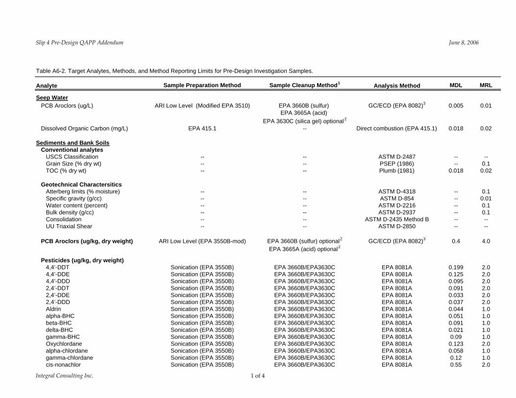
Slip 4 Pre‐Design QAPP Addendum June 8 2006
Table A6-2 Target Analytes Methods and Method Reporting Limits for Pre-Design Investigation Samples
Analyte Sample Preparation Method Sample Cleanup Method1 Analysis Method MDL MRL
Mercury EPA 1311 -- EPA 7471A 00004 01 Selenium EPA 1311 -- EPA 6010B 004 03 Silver EPA 1311 -- EPA 6010B 017 06
TCLP Semivolatiles (mgL) 14-Dichlorobenzene EPA 1311 followed by EPA 3510C -- EPA 8270C (15) 000217 0005 245-Trichlorophenol EPA 1311 followed by EPA 3510C -- EPA 8270C (15) 000115 0025 246-Trichlorophenol EPA 1311 followed by EPA 3510C -- EPA 8270C (15) 00013 0025 24-Dinitrotoluene EPA 1311 followed by EPA 3510C -- EPA 8270C (15) 000157 0025 Hexachlorobenzene EPA 1311 followed by EPA 3510C -- EPA 8270C (15) 000214 0005 Hexachlorobutadiene EPA 1311 followed by EPA 3510C -- EPA 8270C (15) 00027 0005 Hexachloroethane EPA 1311 followed by EPA 3510C -- EPA 8270C (15) 0002025 0005 Nitrobenzene EPA 1311 followed by EPA 3510C -- EPA 8270C (15) 000243 0005 o -Cresol EPA 1311 followed by EPA 3510C -- EPA 8270C (15) 0000915 0005 p -Cresol and m -Cresol (coelute) EPA 1311 followed by EPA 3510C -- EPA 8270C (15) 0001505 0005 Total cresol (summed from above) -- -- -- -- 0010 Pentachlorophenol EPA 1311 followed by EPA 3510C -- EPA 8270C (15) 00061 0005 Pyridine EPA 1311 followed by EPA 3510C -- EPA 8270C (15) -- 0025
TCLP Pesticides (mgL) Chlordane EPA 1311 followed by EPA 3510C EPA 3630CEPA3630C EPA 8081A (110) 00001 00005 Endrin EPA 1311 followed by EPA 3510C EPA 3630CEPA3630C EPA 8081A (110) 000022 0001 Heptachlor EPA 1311 followed by EPA 3510C EPA 3630CEPA3630C EPA 8081A (110) 000009 00005 Heptachlor epoxide EPA 1311 followed by EPA 3510C EPA 3630CEPA3630C EPA 8081A (110) 000015 00005 Lindane EPA 1311 followed by EPA 3510C EPA 3630CEPA3630C EPA 8081A (110) 000014 00005 Methoxychlor EPA 1311 followed by EPA 3510C EPA 3630CEPA3630C EPA 8081A (110) 000097 0005 Toxaphene EPA 1311 followed by EPA 3510C EPA 3630CEPA3630C EPA 8081A (110) -- 01
1 Gel permeation chromatography is required for organics analyses under PSEP Additional cleanups will be used as required to meet MRLs 2 The need for cleanup to be based on screens and the color of extracts (Windward 2004) 3 If more than one Aroclor is detected in a sample the laboratory will choose unique peaks to quantitate each individual Aroclor (ie a peak can only be used in the quantitation of one Aroclor Windward 2004)
Integral Consulting Inc 4 of 4
Slip 4 Pre‐Design QAPP Addendum June 8 2006
Table A7-1 Measurement Quality Objectives Bias Precision Completeness
Analysis (percent) (RPD) (percent) Conventional Analytes
Grain Size ( dry weight) -- plusmn20 95 TOC ( dry weight) 75-125 plusmn30 95
Inorganic Compounds Metals 75-125 plusmn35 95 TCLP Metals -- plusmn35 95
Organic Compounds Pesticides 50-150 plusmn50 95 PCB Aroclors 50-150 plusmn50 95 Semivolatile organic compounds 50-150 plusmn50 95 Total petroleum hydrocarbons 50-150 plusmn50 95 TCLP Semivolatile organic compounds 50-150 plusmn50 95 TCLP Pesticides 50-150 plusmn50 95
Notes RPD = relative percent difference PCB = polychlorinated biphenyl TCLP = Toxicity Characterization Leaching Procedure TOC = total organic carbon
Integral Consulting Inc 1 of 1
Slip 4 Pre‐Design QAPP Addendum June 8 2006
Table B2-1 Sample Containers Preservation Holding Times and Sample Volume
ApproximateContainer Laboratory
Analysis1 Type2 Container Size Subsample Preservation Holding Time
Sediment Samples for Chemical and Geotechnical Testing on Disturbed Samples 34
TOC WMG 2 oz 2 g 4plusmn2ordmC 14 days Grain size WMG 16 oz 100 g 4plusmn2ordmC 6 months Atterberg Limits and Specific Gravity WMG 16 oz 225 g 4plusmn2ordmC 6 months Pesticides WMG 8 oz 25 g 4plusmn2ordmC 14 days40 days5
Diesel- and Oil-Range Hydrocarbons WMG 8 oz 20 g 4plusmn2ordmC 14 days40 days5
Gasoline-Range Hydrocarbons WMG 2 oz 5 g No headspace 14 days 4plusmn2ordmC
(do not freeze) SVOCs WMG 8 oz 50 g 4plusmn2ordmC 14 days40 days5
Metals WMG 8 oz 10 g 4plusmn2ordmC 6 months6
TCLP Metals (includes mercury) WMG 8 oz 100 g 4plusmn2ordmC 6 months6
TCLP SVOCs WMG 8 oz 100 g 4plusmn2ordmC 14 days TCLP Pesticides WMG 8 oz 100 g 4plusmn2ordmC 14 days
Undisturbed Sediment Samples for Geotechnical Analysis
Bulk Density Shelby tube -- -- 4plusmn2ordmC --Consolidation Shelby tube -- -- 4plusmn2ordmC --UU Triaxial Shear Shelby tube -- -- 4plusmn2ordmC --
Seep Water and Equipment Rinse Blanks for Chemical Analysis
Dissolved Organic Carbon7 AG 250 mL 250 mL H2SO4 to pHlt2 28 days cool 4degC
PCB Aroclors7 AG Two - 1000 mL 1000 mL 4plusmn2ordmC 7 days40 days8
Notes AG = Amber glass HDPE = high density polyethylene -- = not applicable WMG = wide mouth glass jar TCLP = Toxicity Characterization Leaching Procedure 1 The laboratory may modify sample jar sizes or analyte groupings 2 Teflonreg-lined lids will be used for glass sample containers Some samples may be combined with other analytes 3 Undisturbed core segments contained in capped Shelby tubes will be submitted for some geotechnical analyses 4 Geotechnical analysis also conducted on archived sediment cores 5 Holding time is 14 days to extraction and extracts must be analyzed within 40 days from extraction 6 Holding time for mercury is 28 days 7 Rinsates submitted for seep sample equipment (DOC and PCB analyses) will be field filtered through 10-microm glass filters 8 Holding time is 7 days to extraction and extracts must be analyzed within 40 days from extraction
Integral Consulting Inc 1 of 1
APPENDIX D
FORMS
CHAIN OF CUSTODYLABORATORY ANALYSIS REQUEST FORM
Page of Turn Around Requested
Report to Phone Analyses Requested NotesComments
Company Fax
Address Proj Name
City Proj Number
State Sampler
Zipcode
Sample ID Sample
Date Sample
Time Sample Matrix
No Con-tainers
Relinquished Received by Special InstructionsNotes
(Signature) (Signature)
Printed name Printed name
Company Company Number of Coolers
Cooler Temp(s)
Date Time Date Time COC Seals Intact
Bottles Intact
Integral Consulting Inc Core Description and Sample Information
STATION PROJECT___________________________ REPLICATE
Field Log by Processing by Coring by Tide Level from MLLW Depth to Mudline Mudline Elev
Date Time
Total Drive Length Recovered Length Recovery Efficiency
Note All elevations depths and distances in feet Core Description - Core Tube Lengths In-Situ Summary Log
Tube Length
Sample No Visual Description
Photo Number
Interpreted Summary
Sample No Acquisition Notes
_1
_2
_3
_4
_5
_6
_7
_8
_9
_10
_11
_12
_13
_14
_15
_16
_17
_18
_1
_2
_3
_4
_5
_6
_7
_8
_9
_10
_11
_12
_13
_14
_15
_16
_17
_18
Core Tube Field Cut Information Sample Test Information Notes
Sample No
Tube Length Interval
Segment Length Sample NoTests
In-Situ Depth
Int
FIELD CHANGE REQUEST Project Number
Project Number Project Name
Field Change No Page to
CHANGE REQUEST Applicable Reference Description of Change
Reason for Change
Impact on Present and Completed Work
(Field Scientist)
(Field Task Leader)
Requested by Date
Acknowledged by Date
FIELD OPERATIONS MANAGER RECOMMENDATION
Recommended Disposition
(Sampling and Analysis Coordinator)
Recommendation by Date
PROJECT MANAGER APPROVAL
Final Deposition
(CERCLA Coordinator)
ApprovedDisapprove d by Date
CORRECTIVE ACTION RECORD
Page of
Audit Report No Date
Report Originator
Person Responsible for Response
DESCRIPTION OF PROBLEM
Date and Time Problem Recognized By
Date of Actual Occurrence By
Analyte Analytical Method
Cause of Problem
CORRECTIVE ACTION PLANNED
Person Responsible for Corrective Action
Date of Corrective Action
Corrective Action Plan Approval Date
DESCRIPTION OF FOLLOW-UP ACTIVITIES
Person Responsible for Follow-up Activities
Date of Follow-up Activity
Final Corrective Action Approval Date
SURFACE SEDIMENTSOIL COLLECTION FORM Project Name Project No Page
Date Crew
Weather
Sampling Method
Time Station Replicate Acceptable grab F Yes F No
Bottom Depth Penetration Depth RPD Depth Analyses before homogenization F VOC F Sulfides F Other Sample ID Type F cobble F gravel F sand C M F F silt clay F organic matter F woodshell fragments Color F drab olive F gray F black F brown F brown surface Odor F none F slight F moderate F strong F sulfidic F petroleum F other Comments
Time Station Replicate Acceptable grab F Yes F No
Bottom Depth Penetration Depth RPD Depth Analyses before homogenization F VOC F Sulfides F Other Sample ID Type F cobble F gravel F sand C M F F silt clay F organic matter F woodshell fragments Color F drab olive F gray F black F brown F brown surface Odor F none F slight F moderate F strong F sulfidic F petroleum F other Comments
Time Station Replicate Acceptable grab F Yes F No
Bottom Depth Penetration Depth RPD Depth Analyses before homogenization F VOC F Sulfides F Other Sample ID Type F cobble F gravel F sand C M F F silt clay F organic matter F woodshell fragments Color F drab olive F gray F black F brown F brown surface Odor F none F slight F moderate F strong F sulfidic F petroleum F other Comments
Time Station Replicate Acceptable grab F Yes F No
Bottom Depth Penetration Depth RPD Depth Analyses before homogenization F VOC F Sulfides F Other Sample ID Type F cobble F gravel F sand C M F F silt clay F organic matter F woodshell fragments Color F drab olive F gray F black F brown F brown surface Odor F none F slight F moderate F strong F sulfidic F petroleum F other Comments
WATER SAMPLE COLLECTION FORM
Station ID _______________________ Project Name
Sample No _____________________ Project Number
Date______________ Collector
Field Parameters
pH Temperature Conductivity Turbidity Comments
__________ __________ __________ ________ __________________________
Sampling Device
Filter None
Sample Containers Collection Time___________
Tag No Container Type Preservative Analytical Method QA Remarks
Comments
Sample Location Sketch
Samplersrsquo Signature______________________________ Date ________________
- SAP - Appendix_c_qapp_06pdf
-
- Figure_A4-1_Org-Chartpdf
-
- Page 1
-
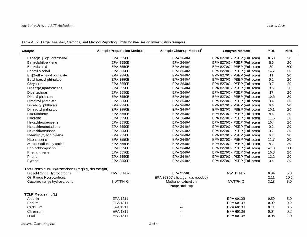
Slip 4 Pre‐Design QAPP Addendum June 8 2006
Table B2-1 Sample Containers Preservation Holding Times and Sample Volume
ApproximateContainer Laboratory
Analysis1 Type2 Container Size Subsample Preservation Holding Time
Sediment Samples for Chemical and Geotechnical Testing on Disturbed Samples 34
TOC WMG 2 oz 2 g 4plusmn2ordmC 14 days Grain size WMG 16 oz 100 g 4plusmn2ordmC 6 months Atterberg Limits and Specific Gravity WMG 16 oz 225 g 4plusmn2ordmC 6 months Pesticides WMG 8 oz 25 g 4plusmn2ordmC 14 days40 days5
Diesel- and Oil-Range Hydrocarbons WMG 8 oz 20 g 4plusmn2ordmC 14 days40 days5
Gasoline-Range Hydrocarbons WMG 2 oz 5 g No headspace 14 days 4plusmn2ordmC
(do not freeze) SVOCs WMG 8 oz 50 g 4plusmn2ordmC 14 days40 days5
Metals WMG 8 oz 10 g 4plusmn2ordmC 6 months6
TCLP Metals (includes mercury) WMG 8 oz 100 g 4plusmn2ordmC 6 months6
TCLP SVOCs WMG 8 oz 100 g 4plusmn2ordmC 14 days TCLP Pesticides WMG 8 oz 100 g 4plusmn2ordmC 14 days
Undisturbed Sediment Samples for Geotechnical Analysis
Bulk Density Shelby tube -- -- 4plusmn2ordmC --Consolidation Shelby tube -- -- 4plusmn2ordmC --UU Triaxial Shear Shelby tube -- -- 4plusmn2ordmC --
Seep Water and Equipment Rinse Blanks for Chemical Analysis
Dissolved Organic Carbon7 AG 250 mL 250 mL H2SO4 to pHlt2 28 days cool 4degC
PCB Aroclors7 AG Two - 1000 mL 1000 mL 4plusmn2ordmC 7 days40 days8
Notes AG = Amber glass HDPE = high density polyethylene -- = not applicable WMG = wide mouth glass jar TCLP = Toxicity Characterization Leaching Procedure 1 The laboratory may modify sample jar sizes or analyte groupings 2 Teflonreg-lined lids will be used for glass sample containers Some samples may be combined with other analytes 3 Undisturbed core segments contained in capped Shelby tubes will be submitted for some geotechnical analyses 4 Geotechnical analysis also conducted on archived sediment cores 5 Holding time is 14 days to extraction and extracts must be analyzed within 40 days from extraction 6 Holding time for mercury is 28 days 7 Rinsates submitted for seep sample equipment (DOC and PCB analyses) will be field filtered through 10-microm glass filters 8 Holding time is 7 days to extraction and extracts must be analyzed within 40 days from extraction
Integral Consulting Inc 1 of 1
APPENDIX D
FORMS
CHAIN OF CUSTODYLABORATORY ANALYSIS REQUEST FORM
Page of Turn Around Requested
Report to Phone Analyses Requested NotesComments
Company Fax
Address Proj Name
City Proj Number
State Sampler
Zipcode
Sample ID Sample
Date Sample
Time Sample Matrix
No Con-tainers
Relinquished Received by Special InstructionsNotes
(Signature) (Signature)
Printed name Printed name
Company Company Number of Coolers
Cooler Temp(s)
Date Time Date Time COC Seals Intact
Bottles Intact
Integral Consulting Inc Core Description and Sample Information
STATION PROJECT___________________________ REPLICATE
Field Log by Processing by Coring by Tide Level from MLLW Depth to Mudline Mudline Elev
Date Time
Total Drive Length Recovered Length Recovery Efficiency
Note All elevations depths and distances in feet Core Description - Core Tube Lengths In-Situ Summary Log
Tube Length
Sample No Visual Description
Photo Number
Interpreted Summary
Sample No Acquisition Notes
_1
_2
_3
_4
_5
_6
_7
_8
_9
_10
_11
_12
_13
_14
_15
_16
_17
_18
_1
_2
_3
_4
_5
_6
_7
_8
_9
_10
_11
_12
_13
_14
_15
_16
_17
_18
Core Tube Field Cut Information Sample Test Information Notes
Sample No
Tube Length Interval
Segment Length Sample NoTests
In-Situ Depth
Int
FIELD CHANGE REQUEST Project Number
Project Number Project Name
Field Change No Page to
CHANGE REQUEST Applicable Reference Description of Change
Reason for Change
Impact on Present and Completed Work
(Field Scientist)
(Field Task Leader)
Requested by Date
Acknowledged by Date
FIELD OPERATIONS MANAGER RECOMMENDATION
Recommended Disposition
(Sampling and Analysis Coordinator)
Recommendation by Date
PROJECT MANAGER APPROVAL
Final Deposition
(CERCLA Coordinator)
ApprovedDisapprove d by Date
CORRECTIVE ACTION RECORD
Page of
Audit Report No Date
Report Originator
Person Responsible for Response
DESCRIPTION OF PROBLEM
Date and Time Problem Recognized By
Date of Actual Occurrence By
Analyte Analytical Method
Cause of Problem
CORRECTIVE ACTION PLANNED
Person Responsible for Corrective Action
Date of Corrective Action
Corrective Action Plan Approval Date
DESCRIPTION OF FOLLOW-UP ACTIVITIES
Person Responsible for Follow-up Activities
Date of Follow-up Activity
Final Corrective Action Approval Date
SURFACE SEDIMENTSOIL COLLECTION FORM Project Name Project No Page
Date Crew
Weather
Sampling Method
Time Station Replicate Acceptable grab F Yes F No
Bottom Depth Penetration Depth RPD Depth Analyses before homogenization F VOC F Sulfides F Other Sample ID Type F cobble F gravel F sand C M F F silt clay F organic matter F woodshell fragments Color F drab olive F gray F black F brown F brown surface Odor F none F slight F moderate F strong F sulfidic F petroleum F other Comments
Time Station Replicate Acceptable grab F Yes F No
Bottom Depth Penetration Depth RPD Depth Analyses before homogenization F VOC F Sulfides F Other Sample ID Type F cobble F gravel F sand C M F F silt clay F organic matter F woodshell fragments Color F drab olive F gray F black F brown F brown surface Odor F none F slight F moderate F strong F sulfidic F petroleum F other Comments
Time Station Replicate Acceptable grab F Yes F No
Bottom Depth Penetration Depth RPD Depth Analyses before homogenization F VOC F Sulfides F Other Sample ID Type F cobble F gravel F sand C M F F silt clay F organic matter F woodshell fragments Color F drab olive F gray F black F brown F brown surface Odor F none F slight F moderate F strong F sulfidic F petroleum F other Comments
Time Station Replicate Acceptable grab F Yes F No
Bottom Depth Penetration Depth RPD Depth Analyses before homogenization F VOC F Sulfides F Other Sample ID Type F cobble F gravel F sand C M F F silt clay F organic matter F woodshell fragments Color F drab olive F gray F black F brown F brown surface Odor F none F slight F moderate F strong F sulfidic F petroleum F other Comments
WATER SAMPLE COLLECTION FORM
Station ID _______________________ Project Name
Sample No _____________________ Project Number
Date______________ Collector
Field Parameters
pH Temperature Conductivity Turbidity Comments
__________ __________ __________ ________ __________________________
Sampling Device
Filter None
Sample Containers Collection Time___________
Tag No Container Type Preservative Analytical Method QA Remarks
Comments
Sample Location Sketch
Samplersrsquo Signature______________________________ Date ________________
- SAP - Appendix_c_qapp_06pdf
-
- Figure_A4-1_Org-Chartpdf
-
- Page 1
-