safety methodology for the operation of a continuous
TRANSCRIPT
HAL Id: ineris-00976188https://hal-ineris.archives-ouvertes.fr/ineris-00976188
Submitted on 9 Apr 2014
HAL is a multi-disciplinary open accessarchive for the deposit and dissemination of sci-entific research documents, whether they are pub-lished or not. The documents may come fromteaching and research institutions in France orabroad, or from public or private research centers.
L’archive ouverte pluridisciplinaire HAL, estdestinée au dépôt et à la diffusion de documentsscientifiques de niveau recherche, publiés ou non,émanant des établissements d’enseignement et derecherche français ou étrangers, des laboratoirespublics ou privés.
Safety methodology for the operation of a continuousintensified reactor
Wassila Benaissa, Sébastien Elgue, Nadine Gabas, Michel Cabassud, DouglasCarson, Michel Demissy
To cite this version:Wassila Benaissa, Sébastien Elgue, Nadine Gabas, Michel Cabassud, Douglas Carson, et al.. Safetymethodology for the operation of a continuous intensified reactor. 12. International Symposiumon Loss Prevention and Safety Promotion in the Process Industry, May 2007, Edimbourg, UnitedKingdom. pp.6. �ineris-00976188�
SAFETY METHODOLOGY FOR THE OPERATION OF A CONTINUOUSINTENSIFIED REACTOR
Wassila Benaissa1,2, Nadine Gabas1, Michel Cabassud1, Michel Demissy2 and Douglas Carson2
Laboratoire de Génie Chimique, UMR 5503 CNRS-INPT-UPS, BP1301, 5 rue Paulin Talabot,31106 Toulouse Cedex 1, France; e-mail: [email protected], [email protected],[email protected], (Institut National de l'Environnement Industriel et des Risques), Parc Technologique ALATA ,
BP 2, 60550 Verneuil-en-Halatte, France; e-mail: [email protected], [email protected]
Today the chemical industry has to deal with new challenges. In addition to producing more andfaster we must produce safer and cleaner. Thusly, new perspectives have emerged to improve pro-duction processes. Green chemistry is certainly one of the most relevant examples but not the only:process intensification and safety also focus on finding creative ways to reduce the use of toxicchemicals and minimize the human and environmental impact. Indeed significant progress hasbeen reached in the development of new reactor technologies: today, miniaturised and continuousprocesses are being developed to attain better heat transfer and safer conditions compared to tra-ditional batch or semi-batch operations. This makes it possible to attain a better chemistry byemploying higher concentrations using less solvent and reaction volumes. In this field, new proto-types of "heat-exchanger/reactors" are a good illustration: built like a plate heat exchanger, addi-tive plates are inserted in order to carry out chemical synthesis. But these new concepts of reactordesign are less familiar than traditional ones, and research is necessary not only to assess their feasi-bilit y and potential but also to develop specific operating protocols.
The present paper deals with the establishment of a new methodology in order to transpose anexothermic reaction from a batch process to a continuous intensified one in terms of safety. Thepropionic anhydride esterification has been chosen to illustrate the different steps which have tobe completed: the methodology first starts with a risk assessment using bibliographic sourcesand calorimetric tools. The bibliography study provides information about the chemical hazardsand the synthesis while the thermodynamic and kinetic behaviours of the reaction are characterisedby experimental data obtained in a reaction calorimeter. The hazard and operability study (HAZOP)is then applied to the intensified process in order to identify potential hazards and to provide anumber of runaway scenarios. Afterwards a dedicated software model has been used to assessthe feasibility of the reaction in the "heat-exchanger/reactor" but also to estimate the temperatureand concentration profiles during synthesis and to determine optimal operating conditions for safecontrol. Using these conditions the reaction has been carried out in the reactor. The good agreementbetween experimental results and the simulation validates the model to describe the behaviour ofthe process during standard run. In the last part of the method the behaviour of the process is simu-lated following probable malfunctions: the adiabatic temperature rise is calculated along the spatialcoordinates of the reactor as well as the time to maximum rate after reactor shut down. Finally, thedynamic evolution of the temperature profiles is obtained by simulation for the different runawayscenarios extracted from the HAZOP study.
KEYWORDS: process safety, intensification, modelling, heat-exchanger/reactor, runaway scenario,intrinsically safer
INTRODUCTIO NToday, the chemical industry has to deal with newchallenges. In addition to produce more and faster, saferand cleaner production must be performed. Thus, alterna-tives have emerged to improve chemical processes. Greenchemistry is certainly one of the most relevant examplebut not the only one. Process intensification can be con-sidered as a method that allows to prevent and reducerisks related to major industrial accidents. Indeed signifi-cant progress has been reached in the development of newreactor technologies: today, miniaturised and continuous
processes are being developed to attain better heat transferand safer conditions compared to traditional batch orsemi-batch operations. These performances authorise tomodify operating conditions by employing higher concen-trations and using less solvent and reaction volumes. Inthis field, new prototypes of "heat-exchanger/reactors"are a good illustration: built like a plate heat-exchanger,internal plates are designed in order to carry out chemicalsynthesis. But these new concepts of reactor designbeing less familiar than traditional ones, research workis necessary not only to assess their feasibility and
potentialities but also to evaluate their efficiency andintrinsic characteristics.
One of the first prototype of "heat-exchanger/reactor" was provided by Alf a Laval Vicarb, called OpenPlate Reactor (OPR). The OPR is composed of severalblocks. Each block is made of one reactive plate, wherethe reactants, products and catalyst of the reactions continu-ously flow, surrounded by two plates containing the utilityfluid, permitting to heat or to cool the reaction mixture(Devatine, 2003). In parallel to experimental characteris-ation of this device, a simulation software tool has beendeveloped (Elgue, 2005). The simulation framework isbased on a complex dynamic model taking into accountthe specificities of the reactor. One of the applications ofthis software is to reproduce and predict the process beha-viour solely by specifying the operating conditions. Theesterification of propionic anhydride by 2-butanol waschosen as a reference synthesis. It has some characteristicswhich make it very interesting (exothermic, relativelysimple to carry out, liquid homogeneous phase) and akinetic model has already been determined (Galvan, 1996)and validated (Benaissa, 2005). After having determinedthe operating conditions, the feasibility of the transpositionof this reaction into the continuous reactor OPR was provedexperimentally (Benaissa, 2006a). Simulation and exper-imental results were in good agreement and this studygave the opportunity, in one hand to formalise steps inorder to transpose an exothermic reaction into a continuousintensified reactor and on the other hand to validate thesimulator. In addition to previous studies (Prat, 2005),these results showed that this new concept of chemicalreactor offers enhanced thermal performances duringnormal operation. An HAZOP analysis carried out on theOPR pilot plant highlighted accidental scenarios for whichthe consequences were not clearly identified (Benaissa,2006b). One major scenario is the stoppage of bothprocess and utility flows. It appears that there is no tool topredict the evolution of the process behaviour after failurewhich can be applied to continuous intensified reactor.
The aim of this work is therefore to propose a method-ology in order to study the thermal consequences of flows
failure in this type of technology. The heat-exchanger/reactor OPR and the esterification of anhydride propionicby 2-butanol are chosen to apply the procedure.
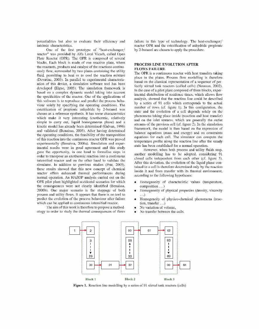
PROCESS LIN E EVOLUTIO N AFTERFLOW S FAILUR EThe OPR is a continuous reactor with heat transfers takingplace in the plates. Process flow modelling is thereforebased on the classical representation of a sequence of per-fectly stirred tank reactors (called cells) (Neuman, 2002).In the case of a pilot plant composed of three blocks, exper-imental distribution of residence times, which allows flowanalysis, showed that the reaction line could be describedby a series of 91 cells which corresponds to the actualnumber of rows (cf. figure 1). In this configuration, thestate and the evolution of a cell depends solely on thephenomena taking place inside (reaction and heat transfer)and on the inlet streams, which are generally the outletstreams of the previous cell (cf. figure 2). In the simulationframework, the model is then based on the expression ofbalance equations (mass and energy) and on constraintsequations for each cell. The simulator can compute thetemperature profile along the reaction line after the steadystate has been established for a normal operation.
However, when both process and utility fluids stop,another modelling has to be adopted, considering 91closed cells independent from each other (cf. figure 3).After this deviation, the evolution of the liquid phase con-tained in a cell is therefore determined only by the reactioninside it and from transfer with its thermal environment,according to the following hypotheses:
• Homogeneity of characteristic values (temperature,composition ...)
• Homogeneity of physical properties (density, viscosity
• Homogeneity of physico-chemical phenomena (reac-tion, transfer .. .)
• No variation of volume,• No transfer between the cells.
29
30 31
60
59•
33
32
— 61 62
63
•89
90 91
Block 1 Block 2 Block 3
Figure 1. Reaction line modelling by a series of 91 stirred tank reactors (cells)
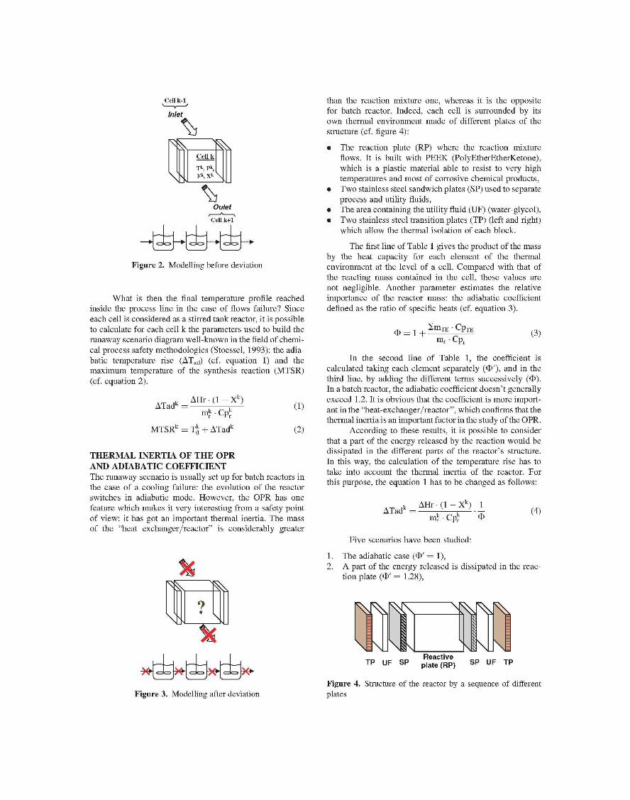
Figure 2. Modelling before deviation
What is then the final temperature profile reachedinside the process line in the case of flows failure? Sinceeach cell is considered as a stirred tank reactor, it is possibleto calculate for each cell k the parameters used to build therunaway scenario diagram well-known in the field of chemi-cal process safety methodologies (Stoessel, 1993): the adia-batic temperature rise (DTad) (cf. equation 1) and themaximum temperature of the synthesis reaction (MTSR)(cf. equation 2).
DHr • (1 - Xk)DTadk =
MTSRk = Tk þ DTadk
(1)
(2)
THERMA L INERTI A OF THE OPRAND ADIABATI C COEFFICIEN TThe runaway scenario is usually set up for batch reactors inthe case of a cooling failure: the evolution of the reactorswitches in adiabatic mode. However, the OPR has onefeature which makes it very interesting from a safety pointof view: it has got an important thermal inertia. The massof the "heat exchanger/reactor" is considerably greater
than the reaction mixture one, whereas it is the oppositefor batch reactor. Indeed, each cell is surrounded by itsown thermal environment made of different plates of thestructure (cf. figure 4):
• The reaction plate (RP) where the reaction mixtureflows. It is built with PEEK (PolyEtherEtherKetone),which is a plastic material able to resist to very hightemperatures and most of corrosive chemical products,
• Two stainless steel sandwich plates (SP) used to separateprocess and utility fluids,
• The area containing the utility fluid (UF) (water-glycol),• Two stainless steel transition plates (TP) (left and right)
which allow the thermal isolation of each block.
The first line of Table 1 gives the product of the massby the heat capacity for each element of the thermalenvironment at the level of a cell. Compared with that ofthe reacting mass contained in the cell, these values arenot negligible. Another parameter estimates the relativeimportance of the reactor mass: the adiabatic coefficientdefined as the ratio of specific heats (cf. equation 3).
SmTE • C P TE
m r • C pr(3)
In the second line of Table 1, the coefficient iscalculated taking each element separately (F0), and in thethird line, by adding the different terms successively (F).In a batch reactor, the adiabatic coefficient doesn't generallyexceed 1.2. It is obvious that the coefficient is more import-ant in the "heat-exchanger/reactor", which confirms that thethermal inertia is an important factor in the study of the OPR.
According to these results, it is possible to considerthat a part of the energy released by the reaction would bedissipated in the different parts of the reactor's structure.In this way, the calculation of the temperature rise has totake into account the thermal inertia of the reactor. Forthis purpose, the equation 1 has to be changed as follows:
(4)k
mkr • C pk
Five scenarios have been studied:
1. The adiabatic case (F0 = 1),2. A part of the energy released is dissipated in the reac-
tion plate (F0 = 1.28),
Reactiveplate (RP) SP UF TP
Figure 3. Modelling after deviationFigure 4. Structure of the reactor by a sequence of differentplates
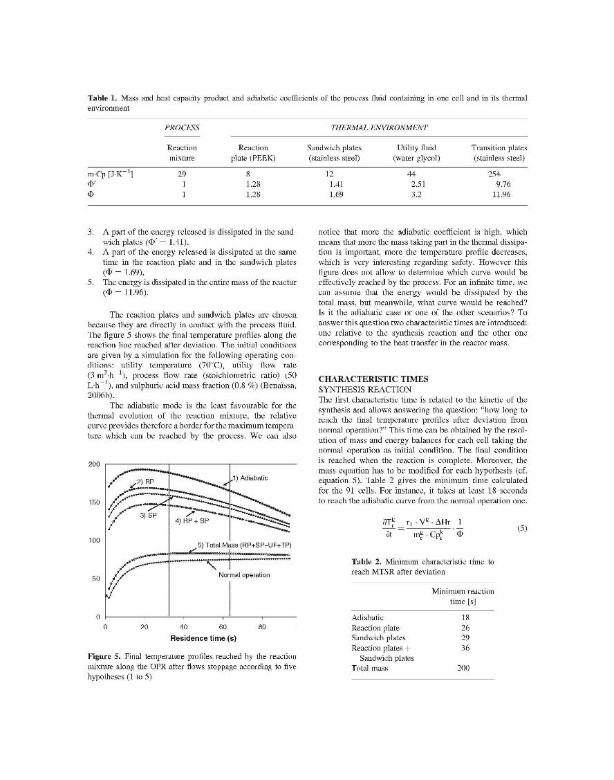
Table 1. Mass and heat capacity product and adiabatic coefficients of the process fluid containing in one cell and in its thermalenvironment
PROCESS
Reactionmixture
THERMAL ENVIRONMENT
Reactionplate (PEEK)
Sandwich plates(stainless steel)
Utilit y fluid(water glycol)
Transition plates(stainless steel)
m.Cp [J.K21] 2911
81.281.28
121.411.69
442.513.2
2549.76
11.96
3. A part of the energy released is dissipated in the sand-wich plates (F0 — 1.41),
4. A part of the energy released is dissipated at the sametime in the reaction plate and in the sandwich plates(F = 1.69),
5. The energy is dissipated in the entire mass of the reactor(F = 11.96).
The reaction plates and sandwich plates are chosenbecause they are directly in contact with the process fluid.The figure 5 shows the final temperature profiles along thereaction line reached after deviation. The initial conditionsare given by a simulation for the following operating con-ditions: utility temperature (708C), utility flow rate(3 m3-h h), process flow rate (stoichiometric ratio) (50L-h ), and sulphuric acid mass fraction (0.8 %) (Benai'ssa,2006b).
The adiabatic mode is the least favourable for thethermal evolution of the reaction mixture, the relativecurve provides therefore a border for the maximum tempera-ture which can be reached by the process. We can also
200
150
1005) Total Mass (RP+SP+UF+TP)
20 40 60 80Residenc e tim e (s)
Figure 5. Final temperature profiles reached by the reactionmixture along the OPR after flows stoppage according to fivehypotheses (1 to 5)
notice that more the adiabatic coefficient is high, whichmeans that more the mass taking part in the thermal dissipa-tion is important, more the temperature profile decreases,which is very interesting regarding safety. However thisfigure does not allow to determine which curve would beeffectively reached by the process. For an infinite time, wecan assume that the energy would be dissipated by thetotal mass, but meanwhile, what curve would be reached?Is it the adiabatic case or one of the other scenarios? Toanswer this question two characteristic times are introduced:one relative to the synthesis reaction and the other onecorresponding to the heat transfer in the reactor mass.
CHARACTERISTI C TIME SSYNTHESIS REACTIONThe first characteristic time is related to the kinetic of thesynthesis and allows answering the question: "how long toreach the final temperature profiles after deviation fromnormal operation?" This time can be obtained by the resol-ution of mass and energy balances for each cell taking thenormal operation as initial condition. The final conditionis reached when the reaction is complete. Moreover, themass equation has to be modified for each hypothesis (cf.equation 5). Table 2 gives the minimum time calculatedfor the 91 cells. For instance, it takes at least 18 secondsto reach the adiabatic curve from the normal operation one.
9T|f
~9t~
• V k • D Hr 1
• Cpkr(5)
Table 2. Minimum characteristic time toreach MTSR after deviation
AdiabaticReaction plateSandwich platesReaction plates þ
Sandwich platesTotal mass
Minimum reactiontime [s]
18262936
200

Table 3. Heat transfer characteristic times for each part of thereactor's structure
Heat transfer time [s]
Reaction plateSandwich plates
120.03
HEAT TRANSFER INSIDE THE OPRThe second time is related to the heat transfer inside thereactor mass and allows answering the question: "Howlong to diffuse the energy in the different element of thestructure?" In fact, when both fluids stop, the transfermode is primarily conductive, each part of the structurebehaves then like a resistance to the transfer. These resist-ances are characterized using the Biot number and theprinciples of the diffusion in solids (Peczalski, 2001). Con-sidering a solid at an initial temperature immerged in a fluidat constant temperature different from solid temperature, thecharacteristic time is defined as the time needed for the solidto reach the fluid temperature (Mc Cabe, 1993). This time isdependant on the thickness of the solid and on its physico-chemical properties. Table 3 gives the times calculated forthe reaction plate and the sandwich plates.
CHOICE OF A SCENARIOThe two characteristic times have to be compared. We canobserve that the heat transfer times are considerablysmaller (sandwich plates) or of the same order of magnitude(reaction plate) than that obtain for the reaction time. There-fore, we can consider the fourth assumption as acceptable.That would mean that in comparison with the adiabaticscenario, the maximum temperature would decrease up to608C (cf figure 5). Thus, the thermal inertia of the "heat-exchanger /reactor" allows it to be intrinsically safer.
CONCLUSIO NThe calculation of two characteristic times shows that partof the energy released by the reaction would be dissipatedat the same time in the plates closer to the reactionmixture: the reaction plate and sandwich plates. Thisapproach reveals an intrinsically safer behaviour of theOPR. This method has to be confronted with experimentalstudies relative on one hand to heat transfer in each plateand on the other hand to experiments with the OPR pilotplant in degraded mode. This result has also to be consideredas a guide for the design of new intensified reactors.
NOTATIONS
F:m:MTSR:
Heat capacity of the reactionmixture [J.mol -K ]flowrate [m3.s21]mass (kg)Maximum temperature of the synthesisreaction in the cell number k [8C]
P: pressure [Pa]r1: reaction rateT: temperature [8C]T0: Steady state temperature reached
during the normal operation inthe cell number k [8C]
X: Steady state conversion reached duringnormal operation in the cell k
A Hr: Heat of the reaction [J.mol21]
GREEK LETTERSA Tadk: Adiabatic temperature rise
in the cell number k [8C]
ABBREVIATIONSPS:RP:TP:UF:
SUBSCRIPTSr:TE:
sandwich platereaction platetransition plateutilit y fluid
reaction mixturethermal environment
SUPERSCRIPTSk: cell index
REFERENCESBenaissa, W., Elgue, S., Gabas, N., Cabassud, M. and Carson, D.,
2005, Transposition of an exothermic reaction to a continuousintensified reactor, Sustainable (Bio)Chemical Process Tech-nology, Jansens/Stankiewicz/Green, 69-77.
Benaissa, W., 2006a, Développement d'une méthodologie pourla conduite en sécurité d'un réacteur continu intensifié, PhDThesis, Institut National Polytechnique de Toulouse, France.
Benaissa, W., Elgue, S., Gabas, N., Cabassud, M., and Carson,D., 2006b, Hazard identification and risk assessment in anintensified "heat exchanger/reactor", CISAP-2, ChemicalEngineering Transactions, 9:133-138.
Devatine, A., Prat, L., Cognet, P., Cabassud, M., Gourdon, C.and Chopard, F., 2003, Process Intensification: performancesevaluation of a new concept <JC open plate reactor 3> , 4t h
European Congress of Chemical Engineering, Grenade,Espagne.
Elgue, S., Devatine, A., Prat, L., Cognet, P., Cabassud, M.,Gourdon, C. and Chopard, F., 2005, Dynamic simulationof a novel intensified reactor, Computer and ChemicalEngineering, submitted.
Galvan, I.M., Zaldivar, J.M., Hernandez, H. and E.Molga,1996, The use of neural networks for fitting complexkinetic data, Computers & Chemical Engineering,20(12):1451-1465.

Mac Cabe, W.L., Smith, J.C. and Harriott, O., 1993, Unit Prat, L., Devatine, A., Cognet, P., Cabassud, M., Gourdon, C.,operations of chemical engineering, MacGraw-Hill, Elgue, S. and Chopard, F., 2005, Performance evaluation ofNew York. a novel concept <JC Open Plate Reactor 3> applied to
Neuman, E.B, 2002, Chemical reactor design, optimization, highly exothermic reactions, Chem. Eng. Technol.,and scaleup, McGraw-Hill. 28:1028-1034.
Peczalski, R., and Laurent, M., 2001, Outils simplifiés de Stoessel, F., 1993, "What is your thermal risk?", Chemicalcalcul, Techniques de l'Ingénieur, F2005. Engineering Progress, 89(10):68-75.