a design methodology for continuous fiber …
TRANSCRIPT

A DESIGN METHODOLOGY FOR CONTINUOUS FIBER ADDITIVE
MANUFACTURING USING ADVANCED COMPUTER AIDED
ENGINEERING TECHNIQUES
by
NICHOLAS VENTER
Presented to the Faculty of the Graduate School of
The University of Texas at Arlington in Partial Fulfillment
of the Requirements
for the Degree of
MASTER OF SCIENCE IN MECHANICAL ENGINEERING
THE UNIVERSITY OF TEXAS AT ARLINGTON
December 2017

ii
Copyright © by Nicholas Venter 2017
All Rights Reserved

iii
Acknowledgements
I first want to thank Dr. Taylor for mentoring and guiding me through my
coursework for the past few years. Additional thanks go to Dr. Adnan and Dr. Dancila for
their support and feedback.
My thanks also go to my friends and family, who have been so supportive of me
in my academic pursuits. I want to extend my gratitude to my grandparents, my father,
Bernard, and my brother, Joshua. I especially want to thank my mother, Cheryl, and
dedicate this work to her. I’m a better person because of her.
December 20, 2017

iv
Abstract
A DESIGN METHODOLOGY FOR CONTINUOUS FIBER ADDITIVE
MANUFACTURING USING ADVANCED COMPUTER AIDED
ENGINEERING TECHNIQUES
Nicholas Venter, MS
The University of Texas at Arlington, 2017
Supervising Professor: Robert Taylor
A design methodology for Continuous Carbon Fiber Additive Manufacturing
(CCFAM) developed using Computer Aided Engineering (CAE) techniques takes
advantage of both the mechanical strength of composite materials and the Fused Filament
Fabrication (FFF) method. By performing topology optimization and Finite Element
Analysis (FEA) on a load-bearing part, engineers can design much lighter optimized parts
that are just as strong as those produced using FFF. This weight reduction is achieved by
relying on the mechanical strength of continuous carbon fibers printed alongside a
traditional thermoplastic matrix. The FFF additive manufacturing method enables the
production of complex shapes, which can match the load-driven, organic geometries
derived from topology optimization and other advanced CAE techniques. The efficacy of
this design methodology has been demonstrated in a design case study of a motor mount
for a vertical take-off and landing drone.
v
Table of Contents
Acknowledgements .............................................................................................................iii
Abstract .............................................................................................................................. iv
List of Illustrations .............................................................................................................. vi
List of Tables ......................................................................................................................vii
Introduction .......................................................................................................... 1
Background .......................................................................................................... 2
2.1 Additive Manufacturing ............................................................................................. 2
2.2 Composites ............................................................................................................. 11
2.3 Composites in Additive Manufacturing ................................................................... 17
2.4 Continuous Fiber Reinforced Polymer 3D Printing ................................................. 22
Methodology ...................................................................................................... 29
3.1 Process Requirements ........................................................................................... 29
3.2 Process Limitations ................................................................................................ 38
3.3 Design Case Study Introduction ............................................................................. 41
Design Specifics ................................................................................................ 42
4.1 Problem Setup and Modeling Guidelines ............................................................... 42
4.2 Analysis .................................................................................................................. 45
4.3 Optimization ............................................................................................................ 49
4.4 Results .................................................................................................................... 50
Conclusion ......................................................................................................... 54
Appendix A: Altair and Eiger Software Screenshots ................................................ 57
Appendix B: Printer and materials ............................................................................ 61

vi
List of Illustrations
Figure 2-1 FFF Process Diagram [4] .................................................................................. 5
Figure 2-2 FFF Discretization [34] ...................................................................................... 7
Figure 2-3 Heat sink Designs Created using a metal 3D printer [10] ............................... 10
Figure 2-4 Biocompatible titanium hip replacement [10] ................................................... 11
Figure 2-1 Hand Layup Example: Applying a ply to tooling [13] ....................................... 13
Figure 2-2 Wet Layup Composite Part Manufacturing [14] ............................................... 14
Figure 2-1 Continuous Carbon Fiber 3D printed part ....................................................... 23
Figure 2-2 Wet nylon (top) vs dry nylon (bottom) ............................................................. 24
Figure 2-3 Onyx Parts [20] [21] ......................................................................................... 27
Figure 3-1 Printing a carbon fiber layer ............................................................................. 35
Figure 3-2 Eiger Support Settings ..................................................................................... 39
Figure 4-1 Motor mount loading condition ........................................................................ 43
Figure 4-2 Optimization and analysis setup ...................................................................... 45
Figure 4-3 Deflection Results from Analysis ..................................................................... 49

vii
List of Tables
Table 3-1 FFF and CFRP Material Comparison [25] [26] [27] .......................................... 36
Table 4-1 Design Comparison .......................................................................................... 51

1
Introduction
Manufacturing methods continue to change as innovative technologies are
developed and old methods are supplanted by them. The basic guidelines and principles
of good manufacturing, however, remain constant as engineers seek to optimize designs
based on customer desires and their derived engineering requirements. A design that
accomplishes a perfect balance between manufacturability, design requirements, and
cost is rare, though every engineer and designer strives to achieve it with each new
project. With the constant advancements in global knowledge, specifically with
manufacturing technology and design techniques, design methodologies are constantly
improving.
As new manufacturing technologies enter the industry, they bring with them their
own set of design constraints, advantages and disadvantages. The full potential of these
technologies cannot be realized until best-practice guidelines have been established.
Additive manufacturing is still recognized as a fairly new technology. Fused Filament
Fabrication (FFF) in particular is used mainly for rapid prototyping. This means that the
parts are built according to designs made with another manufacturing method in mind;
the printed parts are being tested for ease-of-assembly, handling, fit and form. In order to
fully utilize additive manufacturing methods, a design methodology must be established
for producing consistent end-use parts. Developing these design methods requires a
deep understanding of the technology and includes studies that cover the materials used
as well as the effect that process parameters have on material properties [1].
Design methodologies are still being developed for many 3D printing methods,
though several of them have generally accepted rules for producing good quality parts.
The advent of Continuous Fiber Reinforced Polymer (CFRP) 3D printing has brought
much-needed strong mechanical properties to the world of FFF. As such, it is more

2
important than ever to develop a design methodology for producing parts that can fully
take advantage of the manufacturing upside presented by FFF [2], instead of under-
utilizing the technology by only producing prototypes.
This document outlines one such design methodology. It follows part design from
conceptualization, including required loads and boundary conditions, to analysis and
optimization for those loads and finally to final manufacture of the part. This methodology
takes advantage of the manufacturing capabilities of FFF, namely the ability to produce
complex load-driven geometries. These geometries have the advantage of being
stiffened by continuous fibers in specified layers throughout the part. This allows for
additional weight and cost savings in the final design without compromising part strength.
Background
2.1 Additive Manufacturing
Additive manufacturing methods (commonly referred to as 3D printing) offer a
new way to manufacture parts. Instead of traditional subtractive manufacturing methods
in which raw materials are machined into the desired geometries then assembled using
various joining techniques, additive manufacturing techniques add material only as it is
required to build the part. The result is less wasted material and the engineering freedom
to produce far more elaborate geometries. Using additive manufacturing, internal features
and complex, previously non-viable geometries can easily be manufactured [3]. Using
traditional machining methods limits the operator to working on only what they can see
and reach with the tools they have available. They are limited to exactly what size hole
they can drill, bore or ream, the exact size of their cuts, and how much material is
removed based on a given operation. If they want more or less to be removed, for
example, a different tool size is required. If certain internal geometries are to be produced

3
with a specific shape and specific internal open volume, then traditional subtractive
manufacturing may be inadequate to achieving the manufacturing goals because of the
limitations of subtractive manufacturing. There are of course, ways to circumvent these
issues with traditional manufacturing techniques. For specific internal geometries, the
part may be built in stages from multiple joined sections instead of from a solid piece.
This then requires joiners, adhesive or some other mechanism to ensure the part stays
together in its intended shape. These additional joining mechanisms may be undesirable
as they increase the required number of steps, which leads to increased costs and
proclivity for error [5].
Part production can be easier and more time-effective using additive
manufacturing for rapid prototyping and even sometimes for end-use parts. By avoiding
the need for assembly, the time spent in post-processing can be dramatically reduced.
Rapid prototyping is often used for fit-and-form testing in production which speeds up the
design process and cuts down on error by having a physical part that one can test in an
assembly. The more exciting part of additive manufacturing, however, is the possibility of
designing and manufacturing end-use parts. For the Fused Filament Fabrication (FFF)
method, one of the challenges faced in producing end-use load-bearing parts is that the
materials used are relatively weak. Thermoplastic materials ABS and PLA are commonly
used but they lack the required strength and stiffness for many applications. This
naturally limits the usefulness of the process. Some additive manufacturing processes
take advantage of other materials with stronger properties and the Continuous Carbon
Fiber Reinforced Polymer (CFRP) additive manufacturing method is one such process [6.
The most important manufacturing method to understand when discussing CFRP
3D printing is Fused Filament Fabrication (FFF). There are dozens of different
manufacturing techniques all lumped under the terms “3D printing”, “additive

4
manufacturing”, and “rapid prototyping”. Broadly, they refer to the manufacturing
techniques that add material to shape a part, typically in layers, until the final geometry is
realized. Usually what comes to mind when one thinks of 3D printing are the material
extrusion processes Fused Deposition Modeling (FDM) which is also called Fused
Filament Fabrication (FFF). These processes utilize thermoplastic, amorphous polymer
as a filament (typically Acrylonitrile Butadiene Styrene, ABS, or Polylactic Acid, PLA).
This filament is kept in a spool near the printer which is mechanically fed, usually through
a Bowden tube, to the carriage (gantry) which contains a stepper motor, heating element,
and extruder. The filament passes through the heating element, which brings it into its
glass transition temperature in a range reaching up to its melting temperature, and is
extruded through the nozzle by the rest of the material pushing the melted filament from
behind as it’s fed by the stepper motor. The material is extruded out of the nozzle as the
gantry moves in the xy-plane of the printer to trace the outer profile of the part and then a
raster pattern is used to produce the infill. Once the profile for a given layer has
successfully printed, the printer will either move the carriage up in the z-axis or the print
bed down in the z-axis, effectively moving the printing layer up by one. In this way, the
part can be built layer-by-layer until the final form is complete. This process can be seen
detailed in Figure 1.

5
Figure 2-1 FFF Process Diagram [4]
This method comes with a number of advantages. The most obvious advantage
is the design freedom that this process allows [5]. Although almost any geometry can be
created with this process, many require support material. With supporting material
produced alongside build material to prevent drooping and part failure, complex
geometries including internal features can be created. This design freedom allows the
user to take full advantage of Computer Aided Engineering (CAE) tools. The Finite
Element Method (FEM) has long been used as a tool in design for structural analysis
problems, accurately producing stress and deflection solutions. Other CAE tools, namely
topology, shape and size optimizations, use finite element analysis solutions and
optimization algorithms to propose organic, design-driven, and lightweight design
solutions [6].

6
For simple geometries, FFF uses only as much material as is required to produce
the part. Compared to other machining techniques, which cut away unneeded material,
additive manufacturing has relatively little waste. For more complex geometry, support
structures may be required. The G-code instructions can be altered based on a set of
restrictions and parameters, however, to reduce the required amount of support material.
This requires an amount of user experience, else the operator runs the risk of a failed
print, or over-using support. The raster pattern and infill density are both user-set
parameters that can be changed by the designer depending on the application. Parts that
require a certain amount of structural strength and stiffness may require high infill density,
while others can benefit from the reduced weight that a low infill density setting will
provide, for example.
Many of the process constraints come from the hardware used. For example, the
accuracy of the print is limited by the stepper motors used and the operator’s calibration
settings. Print time increases linearly as part tolerances decrease. The industry average
FFF print tolerance averages at 0.2 mm, but can range anywhere from 0.05 mm to 0.5
mm. The resolution of the print is limited by the nozzle size and process parameters (i.e.
printing speed) [3].
Despite the numerous advantages both in manufacturing and in the design
freedom this process allows, there are several drawbacks as well. For one, the part is
built in layers. This means the strength of the part is fundamentally weaker in the z-axis
(in out-of-plane loading) because it is then reliant on the bond between layers of material
[7]. Another drawback is that for any curved or sloped surfaces in the part, if they occur in
the z-direction (meaning that the slope must be expressed in the part over the course of
several layers), then the part will inherently include a discretization or “stair stepping”
effect. This will result in a lower quality surface finish for the sloped layers, which can

7
have negative effects on the end-use part. Fortunately the primary benefit of additive
manufacturing, the design freedom and ability to create complex geometries, can be
used to overcome many of its shortcomings. For example, part orientation, generating
supports, and other parameter changes including infill density, print speed, bead width
and layer height can all be adjusted to minimize or entirely eliminate the negative effects
of the process on a given part. See Figure 2-2 for a model of discretization in FFF.
Figure 2-2 FFF Discretization [34]
.STL files are generated by discretizing a solid model with triangular elements.
These triangular elements cannot fully match a curving or circular geometry, so the .STL
file places the triangles inside the curve to approximate it. When this .STL attempts to
recreate the model in slicing or printing software, if the wall thickness is correctly the
same size as the minimum wall thickness based on bead width, the print will include thin
walls, or may not print material in that area at all because of the discretization effect from
the triangular elements removing material from the model. To fix this, a finer .STL

8
configuration with more triangular elements can be used. Otherwise, slightly increasing
the wall thickness in the solid model and generating a new .STL file can also solve this
problem.
In the printing software (Eiger, KISSlicer, polyprinter, etc.) The part is sliced
according to the user settings previously discussed. These slices are the layer-by-layer
hot-end and gantry movement instructions. These instructions are saved as a .gcode or
.x3g file and relayed to the printer. The printer reads these files and sends the resulting
commands to the appropriate stepper motors and heating elements which will then carry
out the instructions for printing the part.
The FFF method can also be used to print metal parts, which yields a great
increase in strength and stiffness. However, more expensive hardware is required than
that used for thermoplastic filament. The nozzle must be heated up to the appropriate
extruding temperature for whatever material is being used and metals naturally have a
higher melting temperature than thermoplastics. They behave differently from
thermoplastics when extruded at this temperature as well. Instead of a continuous stream
of molten filament, many metal printers will extrude a discontinuous stream of very small
droplets of molten metal [8]. This style of metal 3D printing doesn’t have the same
geometry constraints as Powder Bed Fusion (PBF) techniques.
Powder Bed Fusion techniques use a laser or electron beam to melt, or sinter,
small metal particles. When printing, the part is self-supported by the metal powder.
However, that means that any internal geometries require an opening to allow any
superfluous powder to escape. FFF metal 3D printing doesn’t have this limitation. In fact,
it can produce similarly complex part geometries to FFF thermoplastic printers by making
use of supports in a similar fashion.

9
For PBF, the most common design issue to overcome is part porosity. When
sintering tiny powdered particles of metal, there will inevitably be part porosity where the
particles didn’t perfectly fuse together. Any porosity in a part reduces the part’s strength,
not only because there are small pockets that don’t have material when they should, but
also because those small pockets introduce stress concentrations. These stress
concentrations exacerbate the problem, by driving stresses to the sections of the part that
weren’t properly fused during the sintering process.
Another method is Direct Energy Deposition (DED), which sends a spray of
particles out of a nozzle which are then struck by a laser to build the part layer-by-layer.
This doesn’t have the advantage of being self-supported by a powder bed that PBF
techniques do. This method is good for producing very quick low-quality parts. It is also
useful for using as a kind of spot-repair for any failed parts [9], but isn’t as useful for
producing end-use parts.
Metal 3D printers are good at producing strong, lightweight metal parts quickly.
They are better for small production runs; for larger runs, other methods are more
desirable. It should be noted that, though they are similar, metal 3D printing and
thermoplastic 3D printing are not interchangeable processes. Metal 3D printing requires
more foresight and is generally considered the more complex of the two. Also, the fact
that metal 3D printing techniques exist does not mean that they are always the best
option for a strong part. Often, traditional CNC techniques are just as good or better when
producing a part of sufficiently simple geometry. This can be used to work-around the
unique requirements for metal 3D printers, namely cooling and excess heat
considerations as well as support generation. Supports generated during metal FFF are
often made of metal as well. This makes post-processing extremely labor intensive, and

10
often requires additional machining after the print to remove supports and obtain a
reasonable surface finish.
Another consideration is that longer metal 3DP prints are more likely to fail.
During the process, the metal is repeatedly heated and cooled, which creates a lot of
internal stresses in the part. These stresses cannot be relieved during the printing
process. The main draw of additive manufacturing is the ability to produce complex part
geometries, but this can be detrimental when the part is subjected to these internal
stresses, which continue to increase as the build continues. These stresses cause
warping , which can surpass a minimum acceptable threshold in deviation from the
intended geometry and be considered a failed part. One way to avoid this is to design
cooling channels into the part, but this places another set of design constraints on the
engineer. At the moment, CNC techniques are considered more cost effective and
quicker than metal 3D printing [10].
Figure 2-3 Heat sink Designs Created using a metal 3D printer [10]

11
Figure 2-4 Biocompatible titanium hip replacement [10]
2.2 Composites
Designing composite parts has the advantage of many different potential
manufacturing methods to choose from. These parts are characterized by very high
stiffness and decreased weight when compared to metal parts. However, the material
properties of composite parts are anisotropic, meaning that although they can be strong
in a given direction, they are often much, much weaker in the transverse direction or out-
of-plane directions [11]. This is a function of the fiber orientation and layering method
used to build the part. There are design techniques that can be used to compensate for
this directionality in composite parts, namely alternating fiber direction in successive
plies, or making use of short or chopped fiber mats instead.
The hand layup method for manufacturing composite parts makes use of prepreg
tape, which is rolled out from a spool and cut it to size for each layer required. The layers
are shaped and applied to tooling that to produce the desired geometry. This is then
cured in an autoclave. This method produces strong, lightweight, stiff parts that are useful
in any number of practical applications. However, the process from beginning to end is

12
time consuming and the materials used are expensive for both the designers and the
manufacturers [12].
Composite parts are similar to 3D printed parts in that they are often built up in
layers. Instead of extruding the material through a nozzle, however, the common layup
method uses pre-impregnated (prepreg) tape which has parallel fibers encased in resin.
This tape is cut to size and placed on tooling in the appropriate layup sequence in layers.
While the methods and materials are different, the principle of building a part up in layers
to achieve the desired geometry is very similar between layup and FFF. The layup
process includes no only building the part on tooling layer-by-layer, but also ensuring that
other components are correctly installed including a properly sealed vacuum bag. Once
the lay-up process is complete, the entire assembly is placed in an autoclave. The
autoclave controls both the temperature and pressure applied to the part. This cures the
part and results in a completed composite part ready to use [12].
Prepreg carbon fiber part production is very common. This process involves
utilizing a layup process with pre-impregnated tape. This prepreg consists of thousands
of fibers which are pre-impregnated with resin and bundles into tows. These tows are
then arranged in a single unidirectional ply (tape), or woven into a mat. The tape (or mat)
is cut to size and oriented in such a way that the desired plies are attained. These plies
are placed in the appropriate layup sequence, which is a product of the design
requirements, then placed on tooling to obtain the desired geometry of the part. This is
achieved by manipulating each ply into the correct shape by hand and firmly attaching
them to the previous layer or mold surface. Figure 2-1 shows one such example of the
manufacturer attempting to lay a carbon fiber ply onto tooling that matches the desired
shape of the final part.

13
Figure 2-1 Hand Layup Example: Applying a ply to tooling [13]
This method produces high-quality parts that can have relatively complex
features. It also boasts lower start-up costs than other composite manufacturing
processes. However, production volume is low by necessity and the cost of materials and
labour is high. The adaptability of the design makes up for this, limited only by the skill of
the manufacturer and the complexity of the tooling required, which must itself be
manufactured. Improvements to this process are fairly difficult to come by. In order to
improve production rates and reduce part variability and cost, it is up to the engineer to
design the part such that it is easier to manufacture using this process.
After the layup process is complete, the resulting part is placed in an autoclave,
which heats the part to the appropriate temperature and applies the appropriate pressure
to cure it. The final part is then removed from the autoclave and separated from the
tooling. Barring any additional post-processing, the part is ready to use. This process
yields extremely strong and stiff parts that are far lighter than many equivalent metal part
designs.. They end up being very expensive, however, due to the material and
manufacturing cost. In return, engineers can make use of their high specific strength and
specific stiffness, while understanding the limitations of anisotropic load-bearing parts.

14
Wet layup doesn’t use the same prepreg tape as traditional layup. Instead, dry
fibers are placed on tooling as required and then covered in wet resin. The resin is used
to produce an impregnated composite material. This is done by using rollers, brushes or
other tools to force resin into the fibers (which are often in the form of a fabric for this
manufacturing method). Room-temperature curing resins can be used to simplify the
process even further. This method yields parts with similarly high values for material
properties when compared to prepreg hand layup. Figure 2-2 shows the basic layup
pattern and manufacturing techniques used for this process.
Figure 2-2 Wet Layup Composite Part Manufacturing [14]
One of the main advantages of wet layup is that it has been in use for many
years, so the process is fairly well documented. It has fairly simple manufacturing
principles that can be easily taught. The tooling required is often low cost and room
temperature curing resins eliminate the need for an expensive autoclave. There is a wide
variety of materials that can be used for this method and the parts it produces can obtain
very high fiber contents.
However, the success of this process is entirely dependent on the skills of the
manufacturer. The laminator must check each part for proper resin mixing. If the end part
has a low resin content, the laminate may have dry fibers, which affects the end-product

15
quality of the part. The material properties may also suffer from voids in the part, which
may be critically detrimental for load-bearing parts. Additionally, the available resins are
limited if there is a requirement of being workable by hand. The viscosity will need to be
below a certain value to achieve the desired shapes working by hand. This is often
achieved by diluting the resin, which may compromise the mechanical and thermal
properties of the end part.
Chopped fibers are commonly found in mats that use the same hand layup
process as the one used for prepreg hand layup. Chopped fiber parts take advantage of
short fibers to build composite parts in a way that is less anisotropic than parts built using
long strands of continuous fiber. They are generally easier to manufacture and design
with, while maintaining high weight-to-stiffness ratios. This material exhibits a wide range
of uses. The properties, however, can be affected by the nature of the material itself. The
short fibers are randomly oriented, so they are treated as quasi-isotropic, with averaged
material properties being used [16].
The nature of the randomly oriented fibers makes it much easier during
manufacture to achieve near-perfect coverage of the fibers in resin. This eliminates the
possibility of dry fibers found using other methods, which can be detrimental to the
structural capabilities of the part. Short fiber composites are the easiest to manufacture,
especially when compared to its long-fiber counterparts. However, since the fibers are so
short, this composite type offers the smallest increase in mechanical properties for the
material. They are often manufactured by forming the short fiber composite material into
the final parts with a mold or during extrusion.
One composite manufacturing method, Automated Fiber Placement (AFP),
appears very similar to CFRP 3D printing. However, this process has its own set of
limitations and advantages. The process involves parallel fiber tow lines being placed

16
next to each other on a tool that matches the final shape of the part. These fibers can be
placed in specific orientations on the tooling such that the load paths traveling through
the part follow the stiffer sections, which offers an opportunity for an extra layer of
optimization in design for this process. The fibers are placed on the part in layers until it
reaches the desired thickness. The part is then placed in an autoclave to cure, much like
traditional layup composite manufacturing techniques. This technique has some obvious
advantages over traditional hand layup, namely that the possible part size is much larger.
Also, since the process is automated, the part can be built automatically after setup,
which reduces required man-hours spent actually building the part; after setup, the
machine takes care of the rest.
There are some limitations, however. For example, the geometry of the part is
limited by the tooling. The tooling itself must be manufactured at some point, which
means it is fundamentally constrained by those manufacturing methods. Additionally,
complex geometries, including internal features made all at once in a single process are
difficult to achieve and require an extra level of design (joining). The fact that the part
must be cured in an autoclave may also limit actual applications as the cost of an
autoclave large enough to fit massive parts can greatly increase expected costs. If an
autoclave large enough to accommodate the part can be acquired, however, this process
has the ability to manufacture parts that are much larger than the CFRP 3D printer, which
is limited by the size of the build platform and z-axis height [16].
Automated fiber placement uses a machine that acts similarly to the continuous
carbon fiber 3D printer. It places a prepreg tape in layers on tooling which is heated then
consolidated using a roller or shoe as it’s placed down. In this way, you can build up layer
by layer until the final part geometry of an end-use part is achieved. This method has the
advantage of laying down multiple fibers at a time in any order. However, it doesn’t have

17
the option to place layers without fiber, which decreases design freedom. It also can
produce parts that are very large, which reduces the need for joining operations in the
final assembly (depending on the application). The size and shape is constrained by the
tooling and also by the fact that the end-part must be able to fit into an autoclave for
curing.
2.3 Composites in Additive Manufacturing
The continuous carbon fiber 3D printing method uses the basics of FFF (FDM)
additive manufacturing (rapid prototyping) technologies to build parts layer by layer using
CFRP material. The CFRP material can make use of a number of different materials for
the matrix and fibers, but one common combination uses a nylon filament matrix
impregnated by placing carbon fiber strands in the layers and locations where they are
required. This method takes advantage of the properties of composite parts and of
additive manufacturing by allowing the user to control the location and orientation of the
carbon fiber which, in conjunction with FEM analysis and optimization methods can allow
for reduced costs and material usage. By using two vastly different materials, composites
are made stronger, stiffer, and tougher than either of the two materials would be
separately. The nylon provides toughness and a path for loads to travel along to reach
the stiffer and stronger carbon fiber layers. The carbon fibers provide the part’s strength
and stiffness that composites are known for. Additionally, this combination yields much
lighter parts than those produced using metals that have similar properties.
One massive difference between traditional, subtractive manufactured parts and
composite parts is that traditionally manufactured metal parts can be treated as isotropic
(meaning that they have the same mechanical and thermal properties in every direction),
while composites must be considered anisotropic. This means that the strength, stiffness
and other properties are dependent on the direction the load is applied which places a

18
number of design restrictions on the engineer. This anisotropic nature is true not only for
composites, but also for parts built using FFF [17]. Understanding how a part will react to
various loading and boundary conditions is crucial to designing a successful composite
part. For certain load paths, the part can be extremely stronger by relying on the fiber to
carry the loads. Conversely, for other loading conditions it can be extremely weak as it
may rely on the matrix as well. Because the material properties of the material is
dependent on the loading direction, the designer must realize that relying on the matrix
material to carry a load can lead to part failure by way of delamination or fiber breakage.
Even if the fiber is discounted, FFF produces anisotropic parts as a function of the build
process [17].
The anisotropic nature of composite materials present engineers with the
opportunity to realize tremendous upside, namely in their ability to produce stiff, strong
parts that are lighter than similar parts produced from metal. By 3D printing composite
parts, the user can realize additional upside inherent to additive manufacturing methods.
Additive manufacturing produces parts that can take advantage of complex geometries
and grant a large amount of design freedom to engineers. Being able to print stronger
materials greatly increases the capability of the process. 3D printing structural, load-
bearing parts has always been difficult due to the limited capabilities of available
materials. Because of this, ABS or PLA 3D printed load-bearing parts have all the
capability of printing complex geometries, but are required to increase the volume of
material in the design to achieve reasonable strength for the part. The advent of
composite 3D printers means that stronger materials can be used to alter geometry by
removing now-unnecessary material, while maintaining requisite stiffness [18]. The main
disadvantage of composite parts is that the materials are far more expensive than more
conventional FFF materials (ABS and PLA).

19
Prepreg hand layup is a common composite manufacturing method. CFRP 3D
printers can be used to produce parts that would be difficult or impossible to manufacture
using well-established hand layup techniques [2]. While hand layup (dry and wet) are
both limited by the skill of the manufacturer, CFRP 3D printers will consistently produce
high quality parts according to user-defined settings. The skill of the user for CFRP 3D
printing has more to do with designing for additive manufacturing and understanding the
limitations of the hardware than it does having the physical capabilities and long-term
experience required for hand layup. The geometry of parts made by laying plies up
against tooling are also limited. Tooling places a greater limit on part geometry than it
might appear to at first glance. The tooling itself must be machined, or otherwise
produced. Also, there is no way to get good-quality internal or flowing geometries using
this method. In this way, the CFRP 3D printing method can produce much more
customizable parts with the ability to place individual layers of fibers in a mostly-nylon
part as well as produce more elaborate geometric patterns.
The same advantages hold true for wet layup methods. One important note to
make is that dry fibers are not a common problem with the CFRP 3D printing method.
Instead of the operator using their hands or simple tools to attempt to get an even,
complete coating of resin, the FFF 3D printer simply moves the tool to place matrix
material on every uncovered fiber; it would take a failure of the machine (i.e. a breakdown
or clogged nozzle) to mistakenly place thermoplastic. The reliability of FFF printing
cannot be underestimated when discussing its applications in industry. Other
manufacturing methods may have a relatively high rate of failed parts and require years
of process optimization and refinement using a statistical approach before obtaining
reasonable failure rates. FFF, however, will consistently produce identical parts after the
correct process parameters and printer settings have been decided on. In short, once a

20
print has been successfully manufactured, it is a simple matter to produce an identical
copy of that print. When the print does fail, it is usually the cause of user error. For
example, if the incorrect material is loaded into the machine, but the temperature for the
heating element isn’t updated, it is common for the material to either overheat, burn, and
clog the nozzle or for the underheated un-melted material to become stuck. Since the
thermoplastics used in FFF are hydrophilic, use of old material that has taken in moisture
may also result in a poor print. If the wrong support structure is selected, it is possible for
the part to shift during printing, which can result in misprints or warped parts. Finally,
incorrect orientation of the part or inappropriate use of support material can lead to over-
supported parts (which wastes material and is especially relevant in higher volume print
runs), or under-supported parts which are likely to fail. Each of these causes of failure
can be attributed to an incorrect set up by the operator and are ultimately avoidable.
Once the correct settings are decided upon, applied to the software, and proven to work,
successive prints will rarely fail.
The Fused Filament Fabrication (FFF) method provides the opportunity for
designers to achieve part designs that are designed specifically to accommodate the
load-paths that are generated for a part under a given load [19]. Producing these
optimized, organic and naturally flowing geometries is extremely challenging for
traditional machining methods. In the past, engineers have been required to make
compromises in their part design to accommodate the fact that the design would actually
have to be manufactured. However, with the ability to manufacture just about any
geometry using the FFF method, engineering design freedom has expanded to
unprecedented levels. The search for stronger materials than the common
thermoplastics, ABS and nylon, has been spurred by this design freedom. At the
moment, instead of being constrained by manufacturability, engineers are constrained in

21
this method by the rather poor mechanical properties of parts made out of thermoplastics.
Load-bearing materials like 3D printed metals as well as CFRP and even microfiber
filaments are important for the long-term development of this manufacturing technology. It
allows for parts that have the requisite mechanical and thermal properties to be
manufactured in such a way that the shape of the part takes advantage of the optimized
solution that follows natural load-paths through the part.
The advantages of FFF metal 3D printers are namely that the metals produced
are fully dense and that the process can effectively produce precise internal features [10].
While the process is generally considered to be complicated to design for, once the
appropriate geometry and process parameters are achieved, FFF metal 3DP is extremely
consistent. In any manufacturing application, there are an expected number of failed
parts. This process, however, very rarely fails for a proven print if it is set up correctly.
This predictability is a massive asset in manufacturing. Main disadvantages of this
method include high cost and long processing times. Parts will often take several
iterations before the right process parameters and part geometry are attained. The fine-
tuning period greatly increases the time-to-market for mass-production using this
technology. Two markets that are interested in this type of technology are the automotive
and aerospace industries, where speed and cost aren’t usually prohibiting factors.
Metal 3D printers are also constrained by their lack of available materials. This is
because each printer requires a very specific set of process parameters depending on
the material used. These parameters are different for every material; there is no one-to-
one correlation between two materials. As such, finding the correct settings for a printer
requires a great deal of trial-and-error research. Available materials that are the most
consistent in industry right now are stainless steel, aluminum, titanium, cobalt chrome
and Inconel alloy. The material chosen depends entirely on the application and

22
availability. The surface finish on these parts is quite poor due to the layer-by-layer
approach, similar to thermoplastic parts. The supports generated using this process must
also be removed; CNC machining is a common next-step for metal printed parts both to
remove supports and to machine in any fine features.. The parts usually require
additional operations on the surface. After the build, then, metal 3DP parts will require
additional post-processing and finishing to obtain a reasonably surface finish.
2.4 Continuous Fiber Reinforced Polymer 3D Printing
Continuous Carbon Fiber Reinforced Polymer (CFRP) 3D printing takes
advantage of the speed and flexibility of additive manufacturing with the added benefit of
having the freedom to choose which layers to place fibers and which to leave as matrix
material only. This can be used to attain requisite stiffness in a part while designing to
minimize carbon fiber use to reduce cost. Other benefits include being able to print
complex geometries with internal features thanks to the FFF method [18]. The carbon
fiber itself has a length limitation because, unlike with nylon, ABS and PLA, the fiber must
be cut to length at the end of each printed layer. The minimum length limitation is
constrained by the location of the cutting mechanism (which is located on the gantry for
the Mark Two). The overall process has the same limitations as many additive
manufacturing methods as well as the anisotropic nature shared by other composite
manufacturing processes. One such limitation is that composite parts are notoriously
weak in out-of-plane loading because the stiffness from the fibers only exists in a 2D
plane (they cannot be placed in the z-direction). This same through-the-thickness
weakness is shared by the Mark Two as a function of the additive manufacturing method,
which also places the fibers and resin in layers. The out-of-plane stiffness for the Mark
Two is also fairly low as the part is only held together in that loading condition by the
bonds between layers. These layer bonds are much weaker than the material properties

23
of either the fiber or the matrix. The carbon fiber can be placed in alternating fiber
orientations as with conventional composite parts, so in that way transverse loads can be
treated in a comparable manner to traditional prepreg layup parts.
The Mark Two Continuous Carbon Fiber 3D Printer presents a novel
manufacturing technology that allows designers to take advantage of composite parts by
using the fused filament fabrication additive manufacturing process, namely the complex,
organic and load-driven geometries generated using finite element method optimization
techniques.
Figure 2-1 Continuous Carbon Fiber 3D printed part
The Mark Two Continuous Carbon Fiber 3D Printer utilizes the material extrusion
process (FFF) to take advantage of being able to place continuous lengths of carbon fiber
in the part for added stiffness and create Carbon Fiber Reinforced Plastic (CFRP) parts.
Any composite, by definition, requires two materials: a matrix and a fiber. To
accommodate this requirement, this printer makes use of a two nozzle design. One
nozzle prints nylon while the other is used to place the carbon fiber filament. For each
layer, in order to cease printing the nylon, a command is simply sent to the stepper motor

24
to stop printing. There is a blade that is used to cut the carbon fiber to length for each
layer, which naturally limits the minimum allowable length of fiber to the distance from the
tip of the nozzle to the blade. The fiber is naturally easy to break as a thin filament, but
must be placed side-by-side, doubling back on its length for some fiber configuration
settings. The nylon used for the matrix material is hydrophilic, so it must be kept in a dry-
box. The nylon travels from the dry-box to the printer encased in a Bowden tube. The
nylon is, however, exposed to air at the stepper motor and on the carriage near the
nozzle, meaning that it can still take in moisture at those locations. Before printing with
the nylon, it is important to perform a purge if the printer has not recently been used. This
purge will expel any wet nylon filament from the Bowden tube and only the dry nylon will
be used to print.
Figure 2-2 Wet nylon (top) vs dry nylon (bottom)
One important note to make for the CFRP method is that the strength of the parts
is reliant on the length of the parts. As the size of the part increases, its strength will
naturally decrease [23]. The rule of mixing for this particular method has also been found

25
to be lacking; it doesn’t properly describe the behavior of CFRP parts. Fiber discontinuity
is also a common issue that must be dealt with using this method. The printing pattern is
to blame, as when the fiber layers are set in “contour” mode, the concentric rings begin
on the outer contour first, and print moving inward [23]. There is no way to print so that
the position where the fiber begins will perfectly meet and become continuous with the
point where the fiber ends. By necessity, the process causes the print head to shift
inwards after each contour to continue printing on the same layer. When printing in the
“isotropic” mode, the print head must go out and around in a small loop, meaning at the
ends the fibers aren’t perfectly straight and parallel to one another, but enter return raster
at a slight angle before correcting and becoming parallel again. This loop on the head is a
product of this hairpin turn.
This method is not limited to only carbon fiber and nylon materials. Markforged’s
machine can also print Kevlar, fiberglass, and their own propriety short-chopped fiber
blend called Onyx. The Kevlar and fiberglass materials are similar to the carbon fiber in
that they can be printed as the fiber with nylon as the composite [18]. This plug-and-play
interchangeability is a positive mark towards the efficacy of this process as it allows great
flexibility in material selection and design. Onyx, their proprietary short-chopped fiber
impregnated polymer, seems to be printable just as it is without the need of a cutting
blade. Printing chopped fiber parts is fundamentally different from printing with a
continuous carbon fiber as it is not limited by the orientation of the fiber in each layer, so
the transverse stiffness in a layer will be just as strong as the stiffness in the primary
loading direction. The material is still anisotropic, however, as the material properties of
the part in the through-the-thickness direction will still be weaker than the in-plane
material properties. Other continuous fiber printers may also use the more common FFF

26
materials PLA and ABS, but these are not currently available with the Mark Two. This is a
restriction of the software (Eiger), not the process itself.
Short fiber composites present a different side to composite manufacturing that is
less anisotropic than traditional continuous fiber composites. They can be manufactured
in a few ways, namely by using chopped fiber strand mats or by extrusion. Short fiber
composites must be built in layers similar to how other composite parts are
manufactured. This means that they aren’t perfectly anisotropic, which would give this
composite type a massive advantage over others. Additionally, the randomly oriented
short fibers give the part random mechanical properties, within a reasonable range. This
means that short fiber composites require extensive testing and process refinement to
consistently produce parts that can carry the desired loads. This material type works
perfectly with the FFF 3D printing method because short fiber material can be extruded
out of a nozzle. One advancement in this area uses microfibers instead of short chopped
fibers, and can print a part layer-by-layer to completion using FFF. The parts produced
are discretized in layers, meaning that, as with other 3D printed materials, the resulting
parts are weak in certain loading conditions. The material does increase the strength of
the base matrix material that is impregnated with the microfibers, which increases the
number of possible applications for this manufacturing method. In short, microfiber
impregnated matrix material that can be extruded in the FFF method provides
tremendous opportunity for designing parts that are stiffer and more lightweight than was
previously possible with thermoplastic polymer 3D printers.
Similar to short fiber composites, microfiber composites can produce parts after
being extruded into a given shape. This material works perfectly for additive
manufacturing processes, specifically for FFF. This material is made of nylon that
contains carbon fiber produced as very small microfibers. The resulting material is

27
stronger, tougher, stiffer, and more heat resistant than regular nylon. The fact that it can
be manufactured using the FFF method is great for the additive manufacturing sphere;
stronger materials with little engineering drawback are very desirable. The drawback to
this material, however, is the cost. It is much more expensive that nylon filament, as one
can imagine.
This material is also useful for the continuous carbon fiber 3D printer. Not only
can it print parts with better thermal and mechanical properties than nylon on its own, it
can also be combined with fiberglass, carbon fiber, or Kevlar fibers that the continuous
carbon fiber 3D printer can. This will only further improve the quality of the mechanical
properties in the part. The drawback, of course, is the material cost. This material may
very well be used to strengthen parts, but, unlike with the design methodology for carbon
fiber reinforced nylon, the user cannot tell the machine not to place carbon fiber in certain
sections to minimize cost when the fiber is simultaneously placed in the matrix material
but the matrix material itself is impregnated by additional microfibers. Also, the support
material will also be comprised of the microfiber impregnated nylon, making design for
additive manufacturing to reduce required support material critical to keeping costs low.
The parts printed using this method, then, will always have a relatively high material cost
when compared to CFRP.
Figure 2-3 Onyx Parts [20] [21]

28
Optimization refers to an iterative process that perform multiple analyses on a
part under a given loading condition and with specified material properties to determine
how to best remove material (to lighten the part) or meet some other design objective.
With the advent of CAE tools like finite element analysis, designers can make use of a
numerical iterative optimization process. The results of optimization, then, typically show
the best geometry for the load paths in a structure. For topology optimization, a geometry
is generated based on a set of design variables. Two important methods of numerical
topology optimization in use are the SIMP and ESO (SERA) methods. The SIMP
optimization method optimization generally occurs by labelling each element with a black-
and-white score, or p-factor, of 0 or 1, 0 meaning there shouldn’t be material there and 1
meaning that there should be material there. This p-factor can also generate solutions in
which the density is found to be between 0 and 1. These “grey” areas can be penalized to
obtain nearly pure black and white topologies [6]. Another structural topology optimization
method is the ESO method, which can be generally referred to as a heuristic method. It
makes use of a criterion function which is calculated for each element as part of an
iterative processes that is used to eliminate elements that have the lowest criterion
function (i.e. the 1 is forced to become a 0). This method calculates a large number of
possible solutions with a value assigned to each solution, which is called the performance
index. The global optimum is the solution with the highest performing index out of all of
these solutions (or the lowest depending on what criterion was selected). By making use
of these methods, an optimized design is generated [6].
Non-uniform rational B-spline (NURBS) is a modeling tool used to take the noisy,
organic geometry generated by a topology optimization and create a smooth, useable
surface geometry that can be treated as a solid model [22]. This method is used to more
closely match complex, optimized shapes. It is a more accurate alternative to taking

29
measurements of part cutouts from the optimization results and manually applying them
in a separate solid modeler. While the NURBS tool wasn’t used in this design
methodology, it is worth mentioning as a possible alternative geometric design tool.
Methodology
3.1 Process Requirements
The Carbon Fiber Reinforced Plastic (CFRP) 3D printing method enables the
user to print composite parts using the FFF additive manufacturing process. As with any
composite manufacturing, two distinct materials are required: a matrix and a fiber. The
fiber is the stiffer of the two and generally has a much higher tensile strength. This lends
the part very high strength in the appropriate fiber direction. These stronger, stiffer fibers
are, however, much more brittle than the matrix material. The relatively ductile matrix
material encases the fibers, lending them some measure of protection from transverse
and compressive loads, while transferring loading conditions between layers. The matrix
helps to discourage delamination and connects the fibers together in such a way that
they are less likely to individually snap or break when subjected to an overwhelming load
and instead share the given part load across many fibers which greatly increases the
part’s overall strength and stiffness. This symbiotic relationship between matrix and fiber
is what makes composite parts desirable. They can be much lighter than isotropic metal
parts ,depending on the application, while display similar material properties in their
strong directions. In transverse or out-of-plane loading, they are often much weaker due
to their anisotropic nature, however.
While the two basic materials, fiber and matrix, are required for the process, the
specific materials used can be anything that meets the criteria for each component.
Common materials used in CFRP 3D printing are PLA and nylon . Thermoplastics are
often used in FFF because of their workable nature when heated about the glass

30
transition temperature. The possible fibers extend to carbon fiber, fiberglass, and Kevlar.
The printer used in this investigation is the Markforged Mark Two continuous carbon fiber
3D printer and the materials chosen for the Vayu motor mount case study are nylon and
carbon fiber.
It is worth mentioning that a 3rd material type has recently entered into the CFRP
scene that uses short or microfibers imbedded in the thermoplastic matrix material. One
such material is Onyx. Developed by Markforged, Onyx is a polymer reinforced by short
micro- carbon fibers. It is similar in nature to the material used in short chopped fiber
mats, and shares a number of characteristics with that material. Traditional continuous
fibers are highly anisotropic, but the short chopped fibers offer a slightly more isotropic
material. Since the layering process used in FFF is by necessity used to create Onyx
parts, however, this isotropic nature is limited to the xy-plane as the through-the-
thickness properties still suffer from delamination and reliance on layer bond strength.
This layer-by-layer approach follows the same steps as the FFF process. The
FFF process uses a filament of the printing polymer (usually PLA or ABS, but other
materials like nylon can be used as well). The thermoplastic is stored around a spool.
The filament is fed through the machine to the stepper motor, then from the stepper
motor to the top of the carriage. The carriage is the part of the machine that contains the
heating element and nozzle. Some printers will also contain the stepper motor on the
carriage. This filament is pushed through the heating element, which melts the plastic.
The melted plastic is pushed through the nozzle at the end of the heating element by the
un-melted filament being pushed into the heating element behind it. In this way, the
appropriate amount of material is extruded through the nozzle at a specified bead width
and layer height, dependent on the capabilities of the hardware (the nozzle diameter) and
the setting which are usually specified in the slicing/printing software.

31
CFRP 3D printers follow production steps that are similar to those used in FFF.
The material is extruded out of the nozzle at a given rate. The carriage is moved in the
xy-plane by two belt and pulley systems (one in “x” and one in “y”). Some printers will
allow the carriage to only move in one plane, or perhaps online “x” and “z”. Whichever of
the three directions, x, y and z, is neglected will be picked up by a third pulley or lead
screw in the bed. Generally speaking, a lead screw controls the z movement and pulleys
are used to control the x-y movement. Using these controls, the nozzle is moved on the
carriage to trace the outer contour of the part. The number of “walls” (outer contours) can
be specified in the slicing/printing software. After the contour(s) are printed, the nozzle
comes back to the inside of the part and prints the raster pattern, or infill. This shape
used in the pattern and infill density are two key settings that can be adjusted in the
slicing/printing software. In this way, each layer is traced in contour and then filled in by
the nozzle as it moves along the xy-plane on the carriage. The bed/carriage is then
moved in z by the lead screw up by a distance of one layer height (for the Mark Two, this
distance is 0.125 mm), and the process begins again for the next layer.
This process necessarily produces discretized steps when printing a curve in the
through-the-thickness direction (z-direction) as each subsequent layer must be laid on
the previous layer at an offset distance to create the curve. This stair-stepping effect
leads to a poorer overall surface finish and, depending on the application, can affect fit
and form testing of the part. Another consequence of this effect is that the layers may
separate (delaminate) when subjected to bending or compression loads. In these loading
conditions, the stair-steps act as small stress concentrations that place the highest stress
at the same location as the section between layers that are held together by nothing but
the bond between layers, which is much weaker than the material. Additionally, the raster

32
angle settings may affect the part properties, further complicating the material properties
in the xy-plane [24].
There are several methods to avoid producing discretization in end-use parts, but
sometimes the effect is unavoidable and remains a key limitation of the FFF 3D printing
process. One such method involves simply rotating the part to accommodate the curve in
the xy-plane instead of through several layers in the z-direction. Part orientation is a key
design decision for load-bearing parts. Another possible solution is to print the part in two
pieces, each in a different orientation to eliminate the stair-stepping and then combining
them in a joining process (with adhesive or mechanical fasteners). This involves an extra
few steps of post-processing and joining, however, which eliminates some of the key
advantages of additive manufacturing.
Another key consideration in this process is how to print supports. Many parts will
include complex inner geometries or overhangs. As the printer lays down material to
create an overhang, it will have nothing to print on as it was previously using the earlier
layers as a foundation to apply the material to the new layer. So, for overhangs, support
material is required. Support in FFF is a method by which material is placed such that
overhangs and other complex, unsupported geometries will have something to print on.
The supports have their own generally accepted patterns that are designed to be easy to
remove. Some prints even have a second nozzle on the carriage that prints a totally
different material from the build material (called the support material). The support
material is dependent on the build material. Ease-of-removal is a crucial deciding factor
for support material; some of them can be removed by soaking in a solution or bath which
will dissolve the support material and leave only the build material behind.
For printers with only one nozzle, there is only one appropriate support material
(like the Mark Two); the build material must also be used as support material. This

33
necessitate the use of specific support structures that allow for easy removal of the
support. Because the build and support materials are the same, it is more difficult to
remove. This leads to longer post-processing times to remove the support material and
makes removal of support material from internal geometries anywhere from difficult to
impossible. The Mark Two has default settings for support material that cannot be
changed in Eiger (the slicing and printing software used for the printer). It uses an
accordion-type of support that is meant to be easy to remove by lifting up one end and
pulling all subsequent support off as one piece. However, some geometries, like the
mounting cylinder in the Vayu motor mount case study, make this difficult. This specific
support generation also tends to move or buckle during printing, which leads to burned
parts as the hot nozzle prints the next layer and brushes up against the deformed
support.
For the FFF additive manufacturing method, slicing/printing software is used to
set parameters and develop a tool path for the nozzle to follow during printing. Popular
slicing software includes KISSlicer, Slic3r, MakerBot desktop and FlashPrint. Some of
software, such as MakerBot desktop and FlashPrint will both slice and print internally.
Other printing software require the part to be sliced beforehand. In slicing software, an
STL of the part is imported. The STL file format is does not specify units, so it is important
to visually confirm that the part imported is correct. In the slicing software, various
parameters can be changed including, print speed, extrusion rate, infill density, the raster
pattern, number of walls, number of floor layers, part orientation and others. Another
notable feature is the ability to generate support based on parameters like minimum
offset angle (the angle at each an overhang occurs) and support type (accordion vs tree-
like, or other shapes). When the part is sliced, a layer-by-layer toolpath is generated
according to the inputs available in the software. This layer-by-layer toolpath is

34
communicated to the printer in the form of G-code, which tells the nozzle exactly where to
move, when to extrude material, and which material to extrude as well as communicating
any other parameters specified in the slicing software like extrusion rate and nozzle travel
speed. The printer then follows the G-code line-by-line for each layer according to the
specified user settings to print a completed part.
These basic FFF production steps are followed by the Mark Two to print the
nylon matrix, which is treated as both the build and support materials. The carbon fiber is
printed continuously from a spool that is fed by a stepper motor into a heating element
and through a nozzle much the same as any other thermoplastic filament. The carbon
fiber doesn’t follow the same pattern of contour then raster pattern that the build materials
for FFF generally follow. Instead, the walls are created using nylon so that the fiber is full
enclosed and then the fiber is placed in the infill using a raster pattern that is determined
in the slicing software, Eiger. There is a minimum length of fiber that can be printed which
is determined by the length from the nozzle tip to the cutting knife on the carriage of the
printer. This knife will neatly cut the fiber to length when this minimum length is equal to
the remaining fiber length required to complete the layer. The printing pattern that the
fiber follows is defined by the software as either “concentric” or “isotropic” fiber modes.
The concentric mode causes the printer to print the fiber in concentric rings around the
part that follow its contour. The rings are printed until the minimum length of the fiber for a
contour is reached. Contours that would have been generated that have a total length-to-
print of less than the minimum printable length will not be printed. Isotropic mode causes
the fibers to print some number of walls in concentric mode, while the rest are printed in a
side-by-side continuous raster at a given angle like traditional prepreg tape used for
layup. At the end of each fiber line, the nozzle follows a looping curve at the end of each
line in order to place subsequent fibers side-by-side and parallel to the previous fiber line.

35
There is a setting for the number of fiber walls, which allows the user to decide how many
concentric rings of fiber will be printed to follow the contour for the isotropic mode, which
in turn determines how the length and number of parallel fiber lines that will be printed in
isotropic mode. Figure 3-1 shows a layer of isotropic fibers being printed after a single
contour.
Figure 3-1 Printing a carbon fiber layer
It is important to understand both how the process works and the purpose of
different materials used in the process so that the advantages and limitations of this
manufacturing method can be understood in full. The limitations of printing in layers are
evident in delamination, anisotropic material properties, and limited capabilities with
curved edges in the z-direction. Delamination is an important factor to consider in any
layer-based manufacturing method. One notable comparison can be made with

36
traditional prepreg layup techniques, which use a number of plies with fibers at different
angles to build up the part layer-by-layer. The FFF method has similar problems with
delamination and those issues are compounded when using CFRP. In certain loading
conditions, there is a lot of stress applied at the boundaries between layers. The strength
at these boundaries consists only of the bond strength, instead of the standard material
strength of the matrix or fiber. For the purposes of the Vayu motor mount case study, in
which all of the fibers were printed in the 0°, the strength of the part in the transverse
direction (perpendicular to the fiber direction, or 90°) is essentially the same as the
strength of the nylon.
Table 3-1 FFF and CFRP Material Comparison [25] [26] [27]
From Table 1, nylon has a higher than normal ultimate tensile strength, but a
very low elastic modulus when compared to the other two common thermoplastic printing
materials. This makes the nylon much tougher than either the PLA or ABS materials.
Carbon fiber has the highest stiffness and ultimate tensile strength, of course, which
complements the nylon’s toughness. The resulting composite material makes use of this
combination of tough and durable nylon and the extremely strong and light, but brittle,
carbon fiber. The resulting part is very strong and can make use of the nylon to transfer
transverse and through-the-thickness loads to the carbon fibers. Nylon on its own is less
desirable for structural parts and relies on the strength of the carbon fiber when used in
structural parts. Additionally, though many thermoplastics are hydrophilic, nylon is
PLA ABS Nylon Carbon Fiber
Tensile Strength,
Ultimate (MPa)
48 32 54 700
Elastic Modulus
(GPa)
3.039 2.230 0.94 54
Density (g/cm3) 1.25 1.07 1.10 1.4

37
especially so. For the purpose of 3D printing, nylon must be kept in a dry-box with
regularly replaced desiccant pouches to avoid it absorbing any moisture. If the nylon (or
any other 3D printing thermoplastic) takes on too much water, it becomes impossible to
print with it. The end parts will have a bubbly effect, or fail to bond between layers. It can
lead to excessive warping of the part as well as a massive decrease in its material
properties. The loss of quality in the end-product part is immense. Additionally, the nylon
must be purged before each print as there is some amount of it that is open to absorbing
moisture in the air as it passes from the enclosed Bowden tube through the stepper
motor and as it passes through the enclosed Bowden tube to the nozzle. After each
purge, these two sections of wet nylon are expelled. This action must be performed each
day before the machine can be used to print parts, otherwise the operator runs the risk of
poor quality sections occurring in the part.
The Carbon fiber gives the user the advantage of extremely high stiffness at an
order of magnitude higher than other FFF materials, but comes with its own set of
limitations. For one, the fiber itself is small and difficult to work with. The entire spool of
carbon fiber must remain under tension, else it will come undone. Re-winding the
expelled filament is extremely difficult and time consuming, making initial handling of the
fiber important to timely part delivery. This filament must be simultaneously fed into its
own Bowden tube and kept under tension until it reaches the carbon fiber stepper motor.
It is very easy to accidentally break the fiber as it is being fed into the moving motor
during loading, which can lead to broken pieces of fiber in the tube. The fiber itself must
also be cut to size during printing, meaning that there is a minimum acceptable printable
length of fiber, which places additional design constraints on the user. Each layer will be
one continuous fiber in the isotropic mode (barring the contour walls). In the contour
mode, each contour will have its own separate fiber, which is cut to size by the printer’s

38
knife. This means that in contour mode there is a minimum acceptable contour length,
which can severely limit fiber placement. This can be an issue depending on the loading
conditions of the part.
3.2 Process Limitations
There are also limitations for the process itself. One important limitation to note is
the requirement of proper bonding, both between the first layer and the print bed, and
between subsequent layers. Whenever two different materials are used in printing, it is
important to consider how the two materials will bond with each other between layers.
The purpose of using carbon fiber in the FFF process is to produce CFRP parts that will
guide the load to the stiff, strong fibers. The layering process creates a discretization
effect which can naturally produce stress concentrations in the part, which is undesirable.
The nylon is meant to act as a mechanism for transferring load to the fibers; it is not
meant to carry the brunt of the load itself. This effect exacerbates the FFF process
discretization issue in parts that are built with overhangs or changes in curvature in the
through-the-thickness (z-) direction.
In order to print with the Markforged Mark Two continuous carbon fiber 3D
printer, their proprietary software, Eiger, is required. It runs in browser and utilizes the
cloud to slice the STL. All of the parts and a complete print history are kept in the
software. When a part is uploaded it can be saved in a project folder. The software
comes with complete estimates of total material cost, volume of material used, and an
estimated print time. It includes many of the same settings that other additive
manufacturing software has including an option for controlling infill density, raster
patterns, number of wall layers, number of roof and floor layers, orientation, material
selection, etc. This software automatically places and generates support according to
your settings if it is required, but there aren’t any options for different support types (for
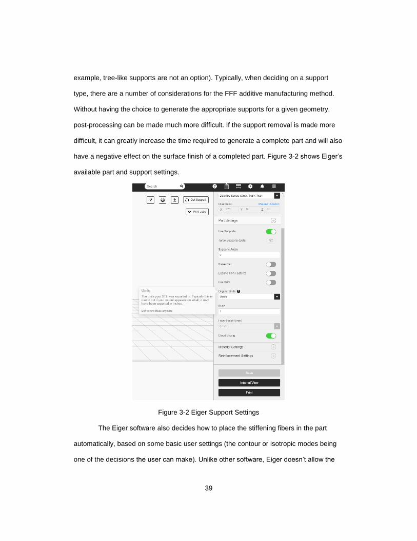
39
example, tree-like supports are not an option). Typically, when deciding on a support
type, there are a number of considerations for the FFF additive manufacturing method.
Without having the choice to generate the appropriate supports for a given geometry,
post-processing can be made much more difficult. If the support removal is made more
difficult, it can greatly increase the time required to generate a complete part and will also
have a negative effect on the surface finish of a completed part. Figure 3-2 shows Eiger’s
available part and support settings.
Figure 3-2 Eiger Support Settings
The Eiger software also decides how to place the stiffening fibers in the part
automatically, based on some basic user settings (the contour or isotropic modes being
one of the decisions the user can make). Unlike other software, Eiger doesn’t allow the

40
user to manually place material. This means that when setting up the print the designer
must consider that they may choose the layer for the fibers to be printed and their basic
orientation, but cannot pick and choose the specific fiber placement (for example, the
user cannot have irregular lengths of fiber on part of a layer, but leave the rest of that
layer without fiber). This is a major design consideration for the user when designing for
the Mark Two. It limits the ability of the user to place filament where it required only. The
results of this limitation are over-designed parts which will be more expensive than is
necessarily required by the design constraints. The carbon fiber filament purchased from
Eiger costs $150.00 for 50 cm3. This comes out to $3.00/cm3, which is of course
extremely expensive. Having the ability to design such that the operator can choose to
use less fiber where it is not needed without the limitations of conventional composite
manufacturing techniques is one of the original draws of the CFRP 3D printing
technology. While the user can take advantage of this design freedom by picking and
choosing individual layers to place the fiber, they are unable to limit or otherwise directly
edit fiber placement in a given layer. Since the carbon fiber, unlike the thermoplastics,
must be cut to length at the end of each layer print, it is further constrained by a minimum
fiber length. For layers below a certain print length dictated by the tool path for the fiber,
fibers cannot be printed. Additionally, all of the settings for material and basic print
settings are decided by the software and cannot be altered by the user. This means that
if the material is not supported directly by Eiger, it cannot be used in the machine. This
rules out the most common FFF printing materials, PLA and ABS, which further limits
design freedom when manufacturing parts with the Mark Two.
Another limitation of the software is the ability to change the infill density. By
having stiff fiber layers in a design, it should allow the designer to limit the amount of
nylon to only what is required to transfer the applied loads to the load-bearing, stiff fiber

41
layers. By reducing the amount of material, both cost and weight can be reduced, while
maintaining stiffness with the fiber layers. However, the infill density on Eiger starts to
give nonsensical weight estimation if the user sets the infill density anywhere lower than
about 5%. When the infill density is decreased the weight of the part should also
decrease, but the estimation in Eiger will show an increase in the amount of material
used. This inaccuracy may affect the quality of the final print, so to ensure quality, the
minimum infill density allowed on the machine should be placed at 5%.
3.3 Design Case Study Introduction
General applications for this manufacturing method can be found in the
aerospace and automotive industries such as with the Vayu motor mount drone case
study. The main advantages of this method are an increase in stiffness when compared
with other additive manufacturing methods and an ability to decrease material use and
weight. The major downside to these improvements is the cost, which is considerably
higher than parts designed and produced with traditional FFF in mind. Industries which
are willing to pay for the increase in performance are most likely to take advantage of this
manufacturing technology. In aerospace applications, weight reduction is often a critical
component of the design decision-making structure. Decreases in weight can lead to
increases in range and payload for the craft, which can pay for the increase in initial cost
over the long term.
The Vayu motor mount design case study clearly illustrates the application of this
design methodology. The part has clear loading conditions that are advantageous for
CFRP. Since the motor mount experiences a bending load, continuous fibers running at a
uniform angle up the length of the part should be used to provide the requisite stiffness.
The motor mount is part of a larger assembly: a drone. This vertical takeoff and landing
drone has four distinct motors mounted to it. The motors each provide lift; the applied
42
load for analysis was considered to be a 17 lbf point load applied to the end of the mount.
Other forces will occur in flight, but they were considered to be negligible. For other part
designs, if these forces cannot be ignored, the design can be modified to include cross
members and reinforced sections to increase part stiffness in those loading conditions.
The drone required a redesign for the motor mounts as the original parts were
made using FFF and, while they were able to meet some of the design requirements, the
more weight that can be saved in this application, the better the overall design. The
purpose, then, was to use the CFRP design methodology guidelines to develop a
redesign for the motor mount that was light and just as stiff as the original part. Additional
consideration had to be made for budget, as the addition of carbon fiber to the part
design greatly increased material costs for the project. By properly sizing the number of
fiber layers required, the cost can be minimized while achieve the original redesign goals.
Design Specifics
4.1 Problem Setup and Modeling Guidelines
The Vayu motor mount case study perfectly illustrates the potential usefulness of
the CFRP 3D printing process. The motor mount consists of two main non-design
sections: 1. a mounting cylinder that connects the mount to the drone and 2. A circular
head that is used to attach the motor to the motor mount. These two sections are
constrained by the assembly requirements for the part. The cylinder must be used to
connect the mount to the drone and the motor must be able to fit and properly mount in
the circular head. These two sections then, are classified as “non-design space”. The
dimensions and features required for appropriate fit and form for final assembly (i.e.
mounting holes in this case) cannot be changed; the engineer is required to design the
final geometry around these conditions. The rest of the geometry, however, can be
changed and as such is labeled “design space”. The mechanism for determining how

43
material should flow from one non-design section to the other is determined by FEM or
other engineering techniques. The precise location and loading conditions of the mount
can be seen in Figure 4-1.
Figure 4-1 Motor mount loading condition
In order to properly model the motor mount, one must decide how to apply the
correct loads and boundary conditions. Based on the function of the part, it is reasonable
to assume that an applied load must be modeled at the location of the motor. According
to Vayu’s calculations, this end of the mount is acted upon by a load of 17 lbf. Since the
part is attached to the drone at the mounting cylinder on the opposite end, the part must
be constrained to reflect this. The inner nodes on the front portion of the mounting
cylinder are constrained such that they cannot move. This is the boundary condition for
this analysis. This combination of loading and boundary conditions puts the mount in a
bending load case, much like a cantilever beam. The point load on the end of the beam
causes a reacting load and moment at the constrained end. The beam, then, experiences
bending. When considering the placement of the fibers, it is important to consider the

44
locations where they will do the most good. In bending, there are two main loads being
applied to the top and bottom of the part. One will experience tension and the other will
experience compression, though which end experiences which load depends on the
direction of the applied point load. The fibers, then, should be placed at the top and
bottom where these loads are being applied such that the fibers carry most of the load
rather than the nylon in order for the part to have the greatest strength and stiffness. The
fibers will be most sorely needed along the length of the mounting cylinder, continuing up
into the cup which holds the rotor. As for where the fibers should be placed, it makes the
most sense to place two sets of fibers since the part is in bending: one near the top end
of the cylinder and one near the bottom end. Though this can be inferred with an
understanding of applied bending, it must still be determined exactly how much fiber will
be required and exactly which layers the fiber will be placed. In order to determine which
layers to place the fibers, one must understand that the fiber placement is also
constrained by the geometry (namely the thickness) of the part, particularly in the circular
end where the motor is placed. Because of this, if the fiber is placed too high or too low
on the cylinder, the software will automatically reduce the amount of useful fiber to match
the layer contour. For it to be most effective, the fiber should travel the entire length of the
part from one tip to the other, without showing any large discontinuities. This lends
consistency to the material properties throughout the length of the part, which will reduce
the chances of part failure or unwanted large deflections under load. This configuration
can be seen in Figure 4-2, which shows the design space in yellow, non-design nylon
and carbon fiber in purple and blue, boundary condition in white and the applied point
load in orange.

45
Figure 4-2 Optimization and analysis setup
The original motor mount was designed by Vayu using ABS plastic, with a
traditional FFF method. It was designed with extra struts and increased thickness to
accommodate the material properties of the ABS. The mount was printed in one piece,
with all mounting holes incorporated into the design of the part. The purpose of the Vayu
motor mount case study was to design a part that was lighter, while maintaining the
requisite stiffness as defined by the original part. Analysis was performed on the part
using Altair Hyperworks and Optistruct. The original part was imported into the software
and meshed. The appropriate material properties were defined in the software as well as
the boundary conditions and applied load. Analysis was then performed on the part to
determine its deflection. This deflection result was used as the baseline stiffness
comparison for the re-designed part. The rest of the design methodology follows from the
following basic requirements: 1.The new part should be lighter than the original part 2.
The new part should have the same stiffness (deflection) as the original part.
4.2 Analysis
Once the loads have been correctly evaluated and modeled analysis and
optimization can begin. The purpose of this analysis will be to determine how many
layers of carbon are required and where they should be placed as well as attaining and
optimized geometry for the nylon matrix “design space” material. Analysis for this case
study was performed in Altair’s Hyperworks using Hypermesh to develop a mesh and

46
Optistruct to perform analysis and optimizations. The part is first modeled in solid
modeling software (in this case, SolidWorks). Then, the geometry is imported into
Hypermesh. Once there, the part is divided into design and non-design space. The non-
design space is specified as previously stated to allow for proper assembly in the final
build. However, the carbon fiber layers are also specified as non-design in this analysis to
ensure that the final geometry has enough material in the layers which require carbon
fiber for the additive manufacturing software, Eiger, to place it. This is done by performing
a Boolean cut on the part to divide it into design and non-design sections. The planes
used to place the cuts define the thickness of the carbon fiber layers as well as the size
of the non-design components. The layer height multiplied by the number of layers will
give the value for the carbon fiber section thickness. Once the cuts have been applied to
the parts, the separated sections of the part should be given their design/non-design
specification by assigning appropriately named components to them.
In order to determine the correct number of layers of carbon fiber to apply to the
part, a size optimization can be utilized. This will yield the optimized thickness for a given
set of conditions. The maximum allowable deflection is set by the analysis results for the
original motor mount design. This sizing operation will result in a desirable thickness; the
appropriate number of layers can be determined from this value by dividing it by the layer
height. This will rarely result in a whole number, so the appropriate number of layers
would be this value rounded up for a safe design. In this case study, the results for
deflection for the first set of analysis was close enough to the original Vayu part’s that a
few iterative analysis studies were enough to define the required number of layers for the
carbon fiber. This was done by first estimating the correct number of layers, performing
analysis and then adjusting that layer thickness based on the deflection results. After a
few iterations, an appropriate layer thickness was attained such that it there is enough

47
carbon fiber to achieve the same deflection results as the analysis from the original part,
but no more than that. The final deflection results show a slightly greater stiffness
calculation than the original part because the layer height is a pre-set condition set in
Eiger for the CFRP 3D printer.
Once the thickness of the carbon fiber layers has been determined, it can be
applied to the part using Boolean cuts. The non-design nylon areas should also be
defined in this way. Cuts should be made at the base of the cylinder where the part is
constrained and the geometry cannot vary due to the mating requirements of that end
and at the mounting holes for the rotor, which also have basic dimensional requirements
for proper mating with the motor. The newly created sections must then be defined by
assigning each new section as its own component (i.e. the two carbon fiber sections will
be a component named “Carbon Fiber – Non-Design” and the nylon sections will be
divided into “Design” and “Non-Design” as shown in Figure 4-1.
Now that the part is properly defined, it can be meshed. Meshing describes the
process of defining the element size and shape and applying it to a solid model.
Choosing the correct settings for a mesh is critical to the success of any FEA. In this
case, a rough mesh was first used. The reasoning for this is two-fold: 1. It reduces
analysis time required to solve the model and 2. The results form a coarse mesh will give
a good indication of approximate fiber layer thickness as well as stress and deflection
results. Once these had been determined, the mesh was refined and made finer in
stages until a stress convergence was reached. The deformation results were also used
as a guideline for mesh resolution. Tetrahedron elements were used to create the mesh,
which formed 3D triangular elements deflection over the geometry. By sizing the
elements after ensuring stress convergence and appropriate mesh resolution based on
deflection, accurate results are ensured.

48
Once the part is meshed, the elements must also be assigned to the appropriate
components. At this point, the components should have properties assigned to them.
Two properties must be created: 1. Carbon Fiber 2. Nylon. They should have the PSolid
designation. These properties in turn require materials to be assigned to them, so two
correlating materials must be created to define the mechanical properties of each
property. Since carbon fiber is anisotropic, it requires a different format than standard
isotropic materials. This format in Hyperworks is called Mat9Ort. This material
designation allows the user to define the material properties (modulus of elasticity, tensile
strength etc.) in each direction compared to each other direction. The stiffness of the
composite must be determined in each direction: E1 based on the strength of the linearly
elastic carbon fiber, as well as E2 and E3 based on the composite stiffness in those
direction, which is reliant on the stiffness of the carbon fibers as well as the nylon matrix.
The Poisson ratio values (ν12 , etc.) can be calculated using the stiffness, as well as the
values for the shear modulus (G12, etc.) . This results in a well-defined anisotropic
material.
This analysis has a number of purposes, including checking the model for stress
convergence and accuracy. The main comparison between the original part and the
redesigned part, however, was to obtain the deflection value which is intended to give
some indication of stiffness for each part. This deflection value was taken at a common
point on the part for both the original and re-design: the top center edge of the cup’s inner
wall, shown in Figure 4-3. This location showed the max deflection for the original part
and the geometry linking the placement of this point to the constrained end is consistent
in subsequent designs.

49
Figure 4-3 Deflection Results from Analysis
With the components, elements, material properties, and loading conditions
appropriately defined, the part is ready for analysis. When the analysis is run, the
software performs the FEM based on the user-defined element settings (size, shape, and
order). The resulting solutions show both the deflection of the part at each node and the
elemental stress throughout the part. These should be used to compare to the original
part for consistency and accuracy. If the results make sense, then an optimization can be
performed. At this point, a .fem file has been created as part of the analysis. The
following topology optimization will take the same FEA as was used to run the static
analysis and will iterate upon it to determine the correct element densities. These
densities will be used to define which elements must be present in order to ensure the
part doesn’t fail and which can be removed without harming its structural integrity.
4.3 Optimization
The topology optimization requires some amount of set up. First, the design
variable must be defined (in this case, the “top-op desvar”). The design variable tells the
software what type of optimization is to be performed. Additional constraining variables

50
must also be selected. For this optimization, stiffness is being maximized (which is the
same as minimizing compliance), with a volume fraction constraint. This will remove
material from the design space iteratively while maintaining stiffness. Results for
incremental increases in volume fraction can be seen in Appendix A.
The SIMP method makes use of FEA by assigning individual elements in the
mesh a density value from 0 to 1 based on the design criterion and optimization
algorithms used. It doesn’t make sense to have elements with partial densities, so a
method must be used to decide if elements with these intermediate density values are
assigned a 0 or 1. This range is assigned a penalty factor by the user to determine the
part’s final geometry based on the optimization results. These elements can be penalized
based on any number of design objectives, including weight minimization, cost
minimization or compliance minimization.
4.4 Results
A design methodology for Continuous Carbon Fiber Additive Manufacturing
(CCFAM) developed using Computer Aided Engineering (CAE) techniques takes
advantage of both the mechanical strength of composite materials and the Fused
Filament Fabrication (FFF) method. The proposed design methodology for CFRP 3D
printing has shown positive results for the Vayu motor mount case study. The resulting
design achieved its design goals of reducing part weight while maintaining similar
stiffness. In order to keep costs down, iterative analysis was performed on the design to
determine the required number of fiber layers as well. The part designed for CFRP meets
its design goals, but is substantially more expensive than the original part built using FFF.
The 36% weight reduction is perhaps substantial enough to warrant further investigation
into uses for this manufacturing technology. Additional refinement of this design

51
methodology may be used in the future to optimize the part for carbon fiber layer
reduction in an effort to reduce costs even further.
Table 4-1 Design Comparison
Original Redesign
Weight (g) 49 (Calculated)
57 (Measured)
39 (Calculated)
36 (Measured)
Cost $1.72 $14.95
Deflection (mm) 0.77 0.72
One general guideline to follow for this printer are to keep in mind the importance
of orientation for the method as well as for fiber placement. For traditional FFF additive
manufacturing, the orientation of the part is critical to print success. As previously
discussed, the orientation of the part can have a major impact on the amount of support
material required, elimination of discretization, and overall surface quality improvements.
When printing with the CFRP 3D printing method, there is a further consideration for the
orientation and layer-location for the carbon fiber filament. Layer-location here means not
only where the fibers are located, but also how they are printed, because their orientation
will change with the orientation of the part, which may limit your design space depending
on the loading condition. The most important consideration is to make sure that the fibers
are adequately placed such that they carry the load in an advantageous manner. If the
part is oriented in such a way that the fiber placement is compromised for a given load in
favour of a slightly better surface finish, then the part is likely to fail. As such, it appears to
be commonplace for this method to sacrifice surface finish and required post-processing
in order to achieve part stiffness in the appropriate locations. The compromise for

52
increased stiffness in return for a worse surface finish is one that must be taken to
properly utilize CFRP parts made with this method. One easy way to increase the surface
finish quality would be to include the option to use different types of supports. The auto-
generated supports in Eiger follow an accordion-type pattern that tends to shift during
printing which can lead to misprints and burned material. The addition of alternate
support types that can be controlled by the user would greatly improve the quality of life
when working with the Eiger software. Removing nylon support material from nylon build
material also decreases part surface quality. Nylon has a very low elastic modulus and
tends to elongate a lot before breaking. Methods other than hand-tearing the material and
filing down the remaining support should be investigated for best surface finish using the
Mark Two.
Another guideline in part design for the method is to continue to consider the infill
density required of the nylon. So much of the design is focused on the carbon fibers and
increasing the stiffness, but the nylon (or whichever matrix material is being used) can be
equally important to achieving the engineering design goals for a project. The infill density
must be considered for weight reduction while maintaining a connection to transfer loads
between carbon fiber layers. As a product of the design for this process, the end part may
contain carbon fiber in every single layer of the print. Even if it is, the nylon infill still
constitutes a significant portion of the part. Most of the weight reduction in part design for
this process will come from removing nylon in the form of cutouts or a vast reduction in
infill density. The quality of the nylon is also crucial to a complete print. The finish on a
part printed with wet nylon is horrendous and the degraded nature of the material
properties will greatly affect part strength. The best way to counteract these effects is to
keep a consistent, watchful eye on the infill density for every print and to respect the

53
nylon build material by keeping it locked inside its dry-box and regularly replacing the
desiccant pouches inside. Dry nylon is crucial to a good build and must not be neglected.
A final consideration for this design process is to respect the limitations of the
Eiger software and take them into consideration when designing the solid model of the
part. For any 3D printing process, it is important to keep in mind the layer height, bead
width, printing speed, and other parameters. It is just as important with this printer to keep
in mind for both materials. Since the software doesn’t allow for manual fiber placement, it
will only place the software in areas where the geometry allows for it. If a wall is too thin
to accommodate the full process for a layer (1. X number of wall layers in nylon 2. A full
contour of the outer geometry in carbon fiber and 3. Isotropic fibers laid down parallel to
each other at a specified angle 4. A raster-pattern infill of nylon to fill in any gaps
according to a specified infill density), then the software simply will not place the fiber
there. It is important to go through the print preview for each part, thoroughly inspecting
each layer (especially the carbon fiber layers) for consistency and correctness. In short,
the user may specify that a layer should contain carbon fiber at certain settings, but the
software can and will ignore that command and place the fiber only where it will
physically fit. The solution to this problem is to use the “measure” tool in SolidWorks (or
the equivalent in whichever solid modeling software is being used) to ensure that the wall
thickness meets at least the minimum thickness required for the printer to follow the given
instructions. If a part will require 2 walls, design with the appropriate bead width in mind.
The same goes for the width of the carbon fiber filament. For the carbon fiber to print
successfully with the “isotropic” setting and the least number of contours (one), the layer
will require three times the printed diameter of the fiber). Alternatively, the settings can be
changed so that each process can be fit into a single layer for the print. For example,

54
reduce the number of walls printed in nylon, or the number of contours specified for the
carbon fiber.
It is especially important to keep these design guidelines in mind when manually
applying cutouts to a part. For a topology optimization, it may be tempting to remove
exactly as much material as is specified by the software. However, the physical
limitations of the manufacturing process must be considered. A smart designer will keep
these limiting factors in mind from the very beginning of the design and when any
changes are made according to optimization or iterative analysis results. In this way, the
number of failed prints can be minimized and the successful prints will perform better.
Conclusion
Based on the results from the presented case study, this design methodology
appears effective. It achieves the design goals for reducing part weight while maintaining
stiffness while at the same time optimizing part dimensions for minimizing material use.
Comparing this manufacturing technology’s design constraints to those of similar
technology’s shows that the CFRP method provides a larger amount of design freedom,
which enables the use of advanced CAE techniques to develop optimized geometry for a
given loading condition. CFRP 3D printing gives designers a reasonable manufacturing
method for physically producing this complex geometry, without compromising the part’s
mechanical strength requirements. While a similar part with a simpler geometry could
have achieved the same stiffness using more traditional composite manufacturing, the
cost of the redesigned part has been reduced due to the design capabilities afforded by
CFRP 3D printing. Similarly, this method produces a lighter part than one that could be
made using traditional machining techniques on aluminum or steel, and a much stiffer
one than could have been produced using FFF or other additive manufacturing methods.

55
There are several potential recommendations for future research on this topic.
For example, due to the difference in stiffness between the fiber and matrix layers, there
is necessarily a difference in strain between them. At the point where the two materials
meet, the nylon or matrix material is attempting to deflect in accordance with the applied
loads, the same as the carbon fiber. However, the fiber is much stiffer so will deflect far
less than the matrix. This causes an Interlaminar shear strain to exist between the matrix
and fiber layers, though for the purposes of this analysis, because of the low deflection
results, this interlaminar shear was considered to be negligible for this analysis. Future
work may include incorporating a model of the behavior between these two layers under
a load.
Additionally, the FFF method itself will cause internal stresses to appear in the
part as hot material is extruded out of the nozzle and laid against cool material, where it
contracts as it cools down. These internal stresses due to the temperature differential
also were not considered in the analysis for this part.
One final consideration for future work involves the nature of thermoplastic
materials. The fibers used in this analysis exhibit linear elastic behavior. However,
thermoplastic materials are viscoelastic, meaning that they do not deform linearly with
respect to time in the same way that the fibers do. The time-dependent nature of these
materials was not captured in this model and is an area of great interest for a more
complete analysis of loaded CFRP parts.
In addition to model improvements, shape optimizations can also be used to
further refine final part geometry by thinning out walls and increasing part height where
necessary (to accommodate the bending load). Improvements to Eiger’s capabilities may
also affect future design work, allowing for the design to be more specifically tailored to

56
the application. This may include a functionality for lower infill density settings, or manual
placement of carbon fiber filament, or any other software improvement.
Each of these areas of interest may improve the CFRP additive manufacturing
design methodology. The motor mount case study for a vertical takeoff and landing drone
provides a good example of its efficacy; the final design is significantly lighter than the
original while remaining slightly stiffer and the end, while minimizing carbon fiber use to
keep costs low. Room for further improvement to this methodology bodes well for the
long-term development of CFRP additive manufacturing technology.

57
Appendix A: Altair and Eiger Software Screenshots
Figure A1: Sample MAT9ORT material properties card (units are in N/mm2)
Figure A2: 60% Volume fraction topology optimization result

58
Figure A3: 70% Volume fraction topology optimization result
Figure A4: 80% Volume fraction topology optimization result

59
Figure A5: Original motor mount (Left) and redesigned Motor Mount (Right) (Eiger)
Figure A6: Original Motor Mount (Left) and redesigned Motor Mount (Right) (Eiger)

60
Figure A7: Layer view of the original motor mount
Figure A8: Layer view of redesigned part
Figure A9: Layer view of redesigned part with carbon fiber

61
Appendix B: Printer and materials
Figure B1: CFRP 3D Printer (Mark Two)
Figure B2: Nylon traveling through a Bowden tube from dry box to printer

62
Figure B3: Carbon Fiber spool
Figure B4: Stepper motors for the nylon and carbon fiber filaments

63
Figure B5: Gantry, heated nozzles and carbon fiber cutting mechanism
Figure B6: Printing carbon fiber layers

64
Figure B7: Completed part with support material
Figure B8: Completed part with support material

65
Bibliography
1. Magalhaes, Laurence Colares. “Build Parameter Influence on FDM Parts
Mechanical Behavior.” COBEM 2011, 24 Oct. 2011.
2. Attaran, Mohsen. “The Rise of 3-D Printing: The Advantages of Additive
Manufacturing over Traditional Manufacturing.” Business Horizons, Sept. 2017,
www-sciencedirect-com.ezproxy.uta.edu/science/article/pii/S0007681317300897.
3. Sossou, Germain. “An Additive Manufacturing Oriented Design Approach to
Mechanical Assemblies.” Journal of Computational Design and Engineering, 6
Nov. 2017, www-sciencedirect-
com.ezproxy.uta.edu/science/article/pii/S2288430017300659.
4. “FFF vs. SLA vs. SLS - 3D Printing.” SD3D Printing, 28 Dec. 2015,
www.sd3d.com/fff-vs-sla-vs-sls/.
5. Bellini, Anna, and Selcuk Guceri. “Mechanical Characterization of Parts
Fabricated Using Fused Deposition Modeling.” Prototyping Journal, 10 Apr.
2015.
6. Rozvany, G. I. N. “A Critical Review of Established Methods of Structural
Topology Optimization.” SpringerLink, Springer-Verlag, 21 Feb. 2008,
link.springer.com/article/10.1007/s00158-007-0217-0.
7. Bellehumeur, Cellne, et al. “Modeling of Bond Formation Between Polymer
Filaments in the Fused Deposition Modeling Process.” Journal of Manufacturing
Processes, 2004, www-sciencedirect-
com.ezproxy.uta.edu/science/article/pii/S1526612504700717.
8. Hazzard, Tracy and Tom, and Leo Svendsen says. “3D Printing Metal, FFF
Style.” 3D Start Point, 22 Mar. 2017, 3dstartpoint.com/3d-printing-metal-fff-style/.

66
9. Koike, Ryo. “Evaluation for Mechanical Characteristics of Inconel6250SUS316L
Joint Produced with Direct Energy Deposition.”Procedia Manufacturing, 2017,
www-sciencedirect-com.ezproxy.uta.edu/science/article/pii/S2351978917308703.
10. Chloe Kow | Aug 04, 2017. “3D Metal Printing: Tips, Trends, and Common
Misconceptions.” Machine Design, 4 Aug. 2017, www.machinedesign.com/3d-
printing/3d-metal-printing-tips-trends-and-common-misconceptions.
11. Nik, Mahdi Arian, et al. “Optimization of Variable Stiffness Composites with
Embedded Defects Induced by Automated Fiber Placement.”www.elsevier.com,
2013.
12. Strong, A. Brent. “Fundamentals of Composites Manufacturing 2nd Edition
(9780872638549).”Fundamentals of Composites Manufacturing 2nd Edition
(9780872638549) - Society of Manufacturing Engineers.
13. “Hand Layup: Understanding the Manual Process.” Taylor & Francis,
www.tandfonline.com/doi/full/10.1080/20550340.2015.1114801.
14. NetComposites. “Wet/Hand Lay-Up.” NetComposites, NetComposites,
netcomposites.com/guide-tools/guide/manufacturing/wethand-lay-up/.
15. Feld, N. “Modelling the Effect of Process-Induced Anisotropy on the Constitutive
Behavior of Chopped Fiber Composites.” Composites Part A: Applied Science
and Manufacturing, Oct. 2017, www-sciencedirect-
com.ezproxy.uta.edu/science/article/pii/S1359835X17302397.
16. Jones, Robert M. Design of Composite Structures: an Introduction to the Many
Aspects of Composite Structures Design. Bull Ridge Publishing, 2015.
17. Ahn, Sung-Hoon, et al. “Anisotropic Material Properties of Fused Deposition
Modeling ABS.”Rapid Prototyping Journal, 2002.

67
18. Dickson, Andrew N., et al. “Fabrication of continuous carbon, glass and Kevlar
fibre reinforced polymer composites using additive
manufacturing.”www.elsevier.com, 2017.
19. Brooks, Hadley, et al. “Design and evaluation of additively manufactured parts
with three dimensional continuous fibre reinforcement.”www.elsevier.com, 2015.
20. Materials.” Markforged Industrial Strength 3D Printing,
markforged.com/materials/.
21. “Thread: Markforged Introduces Nylon/Micro Carbon 3D Printing Filament,
Onyx.” 3D Printing Forum 3D Print Board RSS,
3dprintboard.com/showthread.php?23069-Markforged-Introduces-Nylon-Micro-
Carbon-3D-Printing-Filament-Onyx.
22. Lin, Hongwei. “Adapative Datafitting by the Progressive-Iterative
Approximation.” Computer Aided Geometric Design, 29 Mar. 2012.
23. Klift, Frank van der. “3D Printing of Continuous Carbon Fibre Reinforced Thermo-
Plastic (CFRTP) Tensile Test Specimens.” Open Journal of Composite Materials,
Jan. 2016.
24. Huang, Bin, and Sarat Singamneni. “Raster Angle Mechanics in Fused
Deposition Modelling.” Journal of Composite Materials, 2014.
25. PLA Economy Thermoplastic for Stratasys F123 Series Printers.
usglobalimages.stratasys.com/Main/Files/Material_Spec_Sheets/MSS_FDM_PL
A_0117b_Web.pdf#_ga=2.42824613.1092124968.1511971626-
1033716150.1511971626.
26. “ABS-M30.” 3D Printing Solutions by Stratasys,
www.stratasys.com/materials/fdm/abs-m30.

68
27. “Materials.” Materials – Markforged, support.markforged.com/hc/en-
us/categories/115000131264.
28. Lukaszewicz, Dirk H.-J.A., et al. “Https://Www-Sciencedirect-
Com.ezproxy.uta.edu/Science/Article/Pii/S1359836811005452.” Www.elsevier.co
m, 17 Dec. 2011, www-sciencedirect-
com.ezproxy.uta.edu/science/article/pii/S1359836811005452.
29. Croft, Kevin, et al. “Experimental Study of the Effect of Automated Fiber
Placement Induced Defects on Performance of Composite
Laminates.” Www.elsevier.com, 25 Jan. 2011, www-sciencedirect-
com.ezproxy.uta.edu/science/article/pii/S1359835X11000224.
30. Matsuzaki, Ryosuke, et al. Three-Dimensional Printing of Continuous-Fiber
Composites by in-Nozzle Impregnation. 11 Mar. 2016.
31. Tian, Xiaoyong, et al. “Interface and performance of 3D printed continuous
carbon fiber reinforced PLA composites.”www.elsevier.com, 2016.
32. Soutis, C. “Fibre reinforced composites in aircraft construction.”
www.elsevier.com, 2005.
33. Yang, Li, and Md Ashabul Anam. “An Investigation of Standard Test Part Design
for Additive Manufacturing.”
34. Horvath, Joan. “The 3D Printing Evangelist.” June 2017, 1 Jan. 1970,
www.joanhorvath.com/2017/06//.