safe navigation of a mobile robot considering visibility...
TRANSCRIPT
IEEE TRANSACTIONS ON INDUSTRIAL ELECTRONICS, VOL. 56, NO. 10, OCTOBER 2009 3941
Safe Navigation of a Mobile Robot ConsideringVisibility of Environment
Woojin Chung, Member, IEEE, Seokgyu Kim, Minki Choi, Jaesik Choi, Hoyeon Kim,Chang-bae Moon, and Jae-Bok Song, Member, IEEE
Abstract—We present one approach to achieve safe navigationin an indoor dynamic environment. So far, there have been varioususeful collision avoidance algorithms and path planning schemes.However, those algorithms possess fundamental limitations in thatthe robot can avoid only “visible” ones among surrounded ob-stacles. In a real environment, it is not possible to detect all thedynamic obstacles around the robot. There are many occludedregions due to the limited field of view. In order to avoid collisions,it is desirable to exploit visibility information. This paper pro-poses a safe navigation scheme to reduce collision risk consideringoccluded dynamic obstacles. The robot’s motion is controlled bythe hybrid control scheme. The possibility of collision is duallyreflected to path planning and speed control. The proposed schemeclearly indicates the structural procedure on how to model and toexploit the risk of navigation. The proposed scheme is experimen-tally tested in a real office building. The experimental results showthat the robot moves along the safe path to obtain sufficient fieldof view. In addition, safe speed constraints are applied in motioncontrol. It is experimentally verified that a robot safely navi-gates in dynamic indoor environment by adopting the proposedscheme.
Index Terms—Mobile robot navigation, obstacle avoidance,path planning, speed control.
I. INTRODUCTION
FROM THE viewpoint of autonomous navigation, safety ina human coexisting environment is an essential problem.
On the other hand, high-speed navigation is preferable in orderto increase service efficiency. In order to achieve high-speed
Manuscript received June 14, 2008; revised June 1, 2009. First publishedJune 23, 2009; current version published September 16, 2009. This work wassupported in part by Dasa Robot Corporation as a part of project “Developmentof Patrol and Safety Service Robot Systems,” by the KOSEF Grant funded bythe MEST (R01-2008-000-11995-0), by the MKE under the Human ResourcesDevelopment Program for Convergence Robot Specialists, by the MKE underthe ITRC support program [IITA-2008-(C1090-0803-0006)], and by the Intel-ligent Robotics Development Program, one of the 21st Century Frontier R&DPrograms funded by MKE.
W. Chung, M. Choi, H. Kim, C. Moon, and J.-B. Song are with the De-partment of Mechanical Engineering, Korea University, Seoul 136-713, Korea(e-mail: [email protected]; [email protected]; [email protected]; [email protected]; [email protected]).
S. Kim was with the Department of Mechanical Engineering, Korea Uni-versity, Seoul 136-713, Korea. He is now with the Corporate Research andDevelopment Division, Hyundai–Kia Motors, Gyeonggi-do 445-706, Korea(e-mail: [email protected]).
J. Choi was with the Department of Mechanical Engineering, Korea Uni-versity, Seoul 136-713, Korea. He is now with the Department of ComputerScience, University of Illinois at Urbana–Champaign, Urbana, IL 61801 USA(e-mail: [email protected]).
Color versions of one or more of the figures in this paper are available onlineat http://ieeexplore.ieee.org.
Digital Object Identifier 10.1109/TIE.2009.2025293
navigation, some limitations should be taken into account asfollows:
1) dynamic and mechanical limitations;2) control and computational limitations;3) unexpected dynamic change of environment.
The first problem implies wheel slippage or rollover when arobot makes a sharp cornering or an emergency stop. In practi-cal applications, the first problem is rarely considered becauseother problems cause more strict limitations on the maximumspeed of the mobile robot.
The second problem can be interpreted as a real-time obsta-cle avoidance problem. Navigation speed is limited by sensingaccuracy, processing speed, computational cost, and motioncontrol response. Kanayama et al. proposed a trajectory track-ing algorithm of two wheel differential mobile robots in [1]which guarantees the exponential convergence. Macek et al.proposed a control method for stable and smooth path followingalgorithm in [2] based on the Virtual Vehicle Approach [3].Fox et al. proposed the dynamic window approach (DWA) in[4] based on the curvature velocity method [5]. The DWA isparticularly useful when the robot navigates in dynamic obsta-cle environment. Seder and Petrovic [6] proposed the modifiedDWA algorithm based on the integration of focused D∗ searchalgorithm in [7] considering moving obstacles. Their workshowed improved obstacle avoidance performance by predict-ing the obstacle motions. Minguez et al. proposed the nearnessdiagram (ND) approach in [8]. ND shows superior performanceparticularly in a highly cluttered environment. Quinlan [9] pro-posed path deformation technique that works in real timewhen obstacles block the original path. Montesano et al. ad-dressed the problem of modeling obstacles, and integrationof obstacle information in a local motion planning in [10]. Amobile robot can avoid “visible” obstacles by adopting existingtechnologies.
Our major scope in this paper is to solve the third problemaddressed above. Suppose that a person drives along a narrowroad without any traffic signals. He may reduce speed whenapproaching a junction. It is natural to assume that there mightbe dynamic obstacles in occluded regions. Sometimes a driverchooses a detour path to obtain sufficient field of view. Thepurpose of this paper is to derive the risk of potential collisionwith occluded dynamic obstacles, and to establish a generalcontrol scheme to cope with the risk.
There have been some works to deal with unexpected col-lision and visibility problems. Sadou et al. [11] focused onthe occluded obstacles. The scope of unexpected obstacles is
0278-0046/$26.00 © 2009 IEEE
3942 IEEE TRANSACTIONS ON INDUSTRIAL ELECTRONICS, VOL. 56, NO. 10, OCTOBER 2009
limited to the occluded obstacles on the path, and the path isalways fixed. Another approach is to utilize navigation expe-riences to predict the human walking pattern in [12]. It wasshown that the robot can provide appropriate mobile servicesby monitoring and utilizing patterns of people. The work in[12] shows an example to deal with environmental changes.Krishna et al. [13] computed the safe velocity profile alongthe path and modified the path near the occluded region. Thework also shows a speed control strategy for safety. However,it is required to develop a general approach to combine the pathplanning and the speed control to cope with occluded dynamicobstacles. Another example of speed control can be found in[14]. Well-defined speed constraints are established consideringvehicle features in [14]. However, there is no scheme for pathmodification. The major advantage of this paper is to suggesta generalized procedure to deal with both path planning andspeed control.
In this paper, we establish a safe navigation scheme from twoaspects. The first aspect is path planning. Most of the existingpath planners only focus on detectable obstacles. In addition,the optimality is defined in terms of moving distance in conven-tional planners. However, the shortest path is not necessarilysafe in many cases. It will be shown that the path plannershould reflect the risk of possible collision with occludedobstacles. The collision risk is quantitatively modeled throughthe intrinsic cost of the gradient method, which was introducedin [15].
The second aspect is deriving speed constraints. Once arobot’s path is given, allowable maximum speed can be explic-itly derived. The speed constraint is applied through the DWAin [4]. The specific criterion on deciding maximum velocitywas an open problem in [4]. This paper derives an explicitcondition on the maximum speed in order to avoid collision.A part of this paper was introduced in [16]. Related navigationissues including localization and control architecture designcan be seen in [17]–[19]. In those works, development of themultifunctional mobile service robot was presented. The inte-grated localization strategy was developed based on laser rangefinder readings. The architecture is a hybrid reactive-deliberatescheme including the Petri Net-based behavior selection con-trol scheme. Some recent robotic applications can be foundin [22]–[24].
In this paper, we propose a structural navigation schemeimporting the potential collision risks by considering the vis-ibility information without loss of generality. Previous obstacleavoidance techniques deal with detected moving obstacles. Theidea of this paper is that it is worth considering the field ofview limitations of sensors and the collision risk by occludedmoving obstacles. In this paper, we quantitatively derive thecollision risk and establish path optimization and speed con-trol strategies. The proposed scheme will be experimentallyverified.
This paper is organized as follows. Section II describeshow to compute occluded regions and the risk of unexpectedcollision. Then, we propose path planning and motion controlschemes to achieve safe navigation. Simulations and experi-mental verifications are made in Section III. Some concludingremarks are given in Section IV.
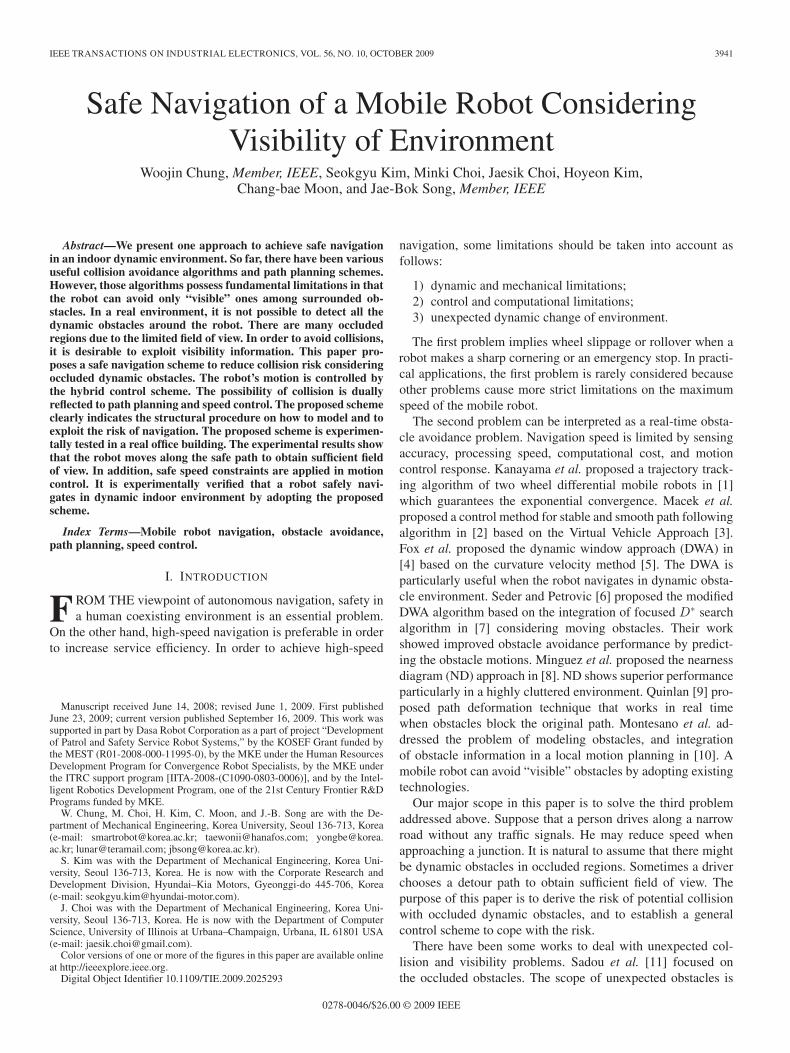
Fig. 1. Occluded reachable regions and a dynamic obstacle.
II. NAVIGATION RISK MODELING
CONSIDERING VISIBILITY
A. Collision Risk Due to Occlusion
Once we have an environmental map, we can find the regionwhere the field of view is geometrically obstructed. Con-sidering the dynamic capacity of a robot and the speed of adynamic obstacle, the collision distance can be computed as thefollowing:
ddelay = tdelay × (vr + vobs) (1)
dbreak = v2r /(2 × arobot) (2)
dobs = vobs × vr/arobot (3)
dcollision = ddelay + dbreak + dobs. (4)
The collision distance dcollision implies the minimum clear-ance which should be guaranteed to avoid collision with adynamic obstacle. The robot should be able to make a completeemergency stop in the range of dcollision. ddelay is caused bythe time delay of sensors and controllers after detecting anobstacle around the robot. dbreak is a breaking distance of arobot, and it is determined by the dynamic control performanceof a robot. dobs is the moving distance of the obstacle duringthe deceleration time of a robot before making a complete stop.Fig. 1 shows the conceptual illustration of dcollision. vr, vobs,and arobot are the speed of a robot, the speed of an obstacle,and the acceleration of a robot, respectively.
Fig. 1 shows the risk of potential collision with dynamicobstacles from occluded regions when a robot approaches ajunction. Fig. 1 also shows a reachable region of a robot whenvr = 1 m/s and vobs = 4 m/s. Since the exact computation ofnonholonomic robot’s reachable region is computationally ex-pensive, we have adopted the wavefront propagation algorithmin [20] for approximate computation of reachable regions.
The occluded area is defined as the difference between thereachable area and the visible area. The reachable area is therobot’s neighborhood considering dcollision. The visible area iscomputed by the ray tracing method. The occluded reachableregion of a robot can be considered as a risky area. The riskyposition is calculated from the collision distance dcollision using(4). In most cases, arobot and tdelay can be assumed to beconstants. Therefore, the risky area is dependent on vr and vobs.
The existence of occluded regions over the entire workspacecan be easily obtained. When the occluded area exists, the robot
CHUNG et al.: SAFE NAVIGATION OF MOBILE ROBOT CONSIDERING VISIBILITY OF ENVIRONMENT 3943
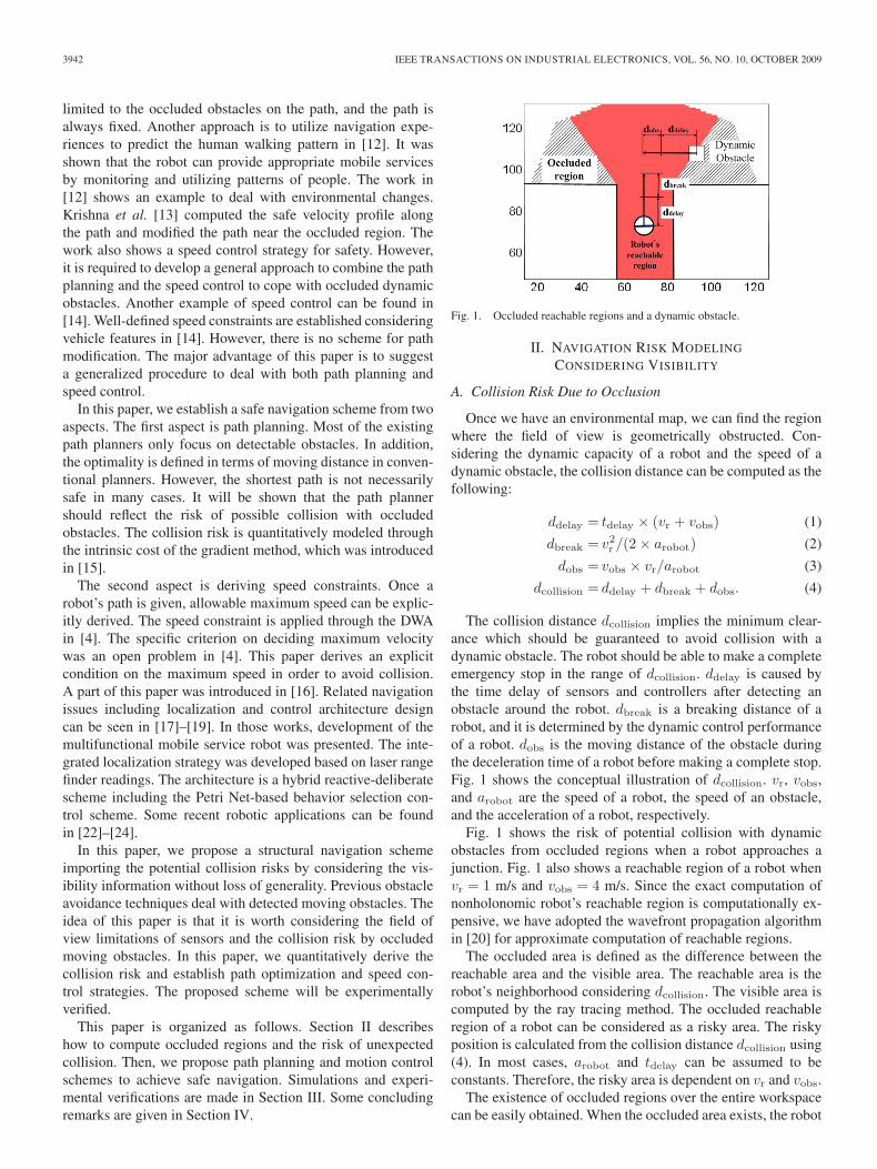
Fig. 2. Computation of regional risk due to potential collision. (a) Realenvironment. (b) Computed risky area due to occlusion.
position is registered as a risky position. Therefore, the set ofrisky positions is registered to a map. This step corresponds toa preprocessing step to model the risk of collision.
Fig. 2(a) shows real environment in a conventional officebuilding. Fig. 2(b) shows the computed risky regions. It isclear that the risky regions are located around the corner or apillar. The computational result matches well with our dailyexperience on the risky area, where unexpected collisions mighttake place.
B. Speed Constraints
Real environments are mostly polygonal, and there aresome particular points which limit visibility. More specifically,convex edges are extreme points which limit field of view, asshown in Fig. 1(a). With the environmental map, convex edgescan be easily extracted.
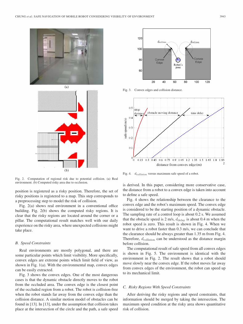
Fig. 3 shows the convex edges. One of the most dangerouscases is that the dynamic obstacle directly moves to the robotfrom the occluded area. The convex edge is the closest pointof the occluded region from a robot. The robot is collision-freewhen the robot stands far away from the convex edge than thecollision distance. A similar motion model of obstacles can befound in [13]. In [13], under the assumption that collision takesplace at the intersection of the circle and the path, a safe speed
Fig. 3. Convex edges and collision distance.
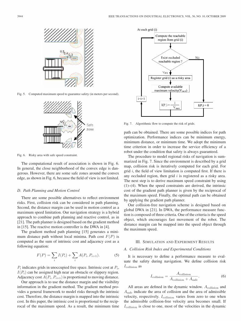
Fig. 4. dcollision versus maximum safe speed of a robot.
is derived. In this paper, considering more conservative case,the distance from a robot to a convex edge is taken into accountto define a safe speed.
Fig. 4 shows the relationship between the clearance to theconvex edge and the robot’s maximum speed. The convex edgeis considered to be the starting position of a dynamic obstacle.The sampling rate of a control loop is about 0.2 s. We assumedthat the obstacle speed is 2 m/s, ddelay is about 0.4 m when therobot speed is zero. This result is shown in Fig. 4. When wewant to drive a robot faster than 0.3 m/s, we can conclude thatthe clearance should be always greater than 1.35 m from Fig. 4.Therefore, dcollision can be understood as the distance marginbefore collision.
The computational result of safe speed from all convex edgesis shown in Fig. 5. The environment is identical with theenvironment in Fig. 2. The result shows that a robot shouldmove slowly near the convex edge. If the robot moves far awayfrom convex edges of the environment, the robot can speed upto its mechanical limit.
C. Risky Regions With Speed Constraints
After deriving the risky regions and speed constraints, thatinformation should be merged by taking the intersection. Themaximum speed condition at the risky area shows quantitativerisk of collision.
3944 IEEE TRANSACTIONS ON INDUSTRIAL ELECTRONICS, VOL. 56, NO. 10, OCTOBER 2009
Fig. 5. Computed maximum speed to guarantee safety (in meters per second).
Fig. 6. Risky area with safe speed constraint.
The computational result of association is shown in Fig. 6.In general, the close neighborhood of the convex edge is dan-gerous. However, there are some safe zones around the convexedge, as shown in Fig. 6, because the field of view is not limited.
D. Path Planning and Motion Control
There are some possible alternatives to reflect environmentrisks. First, collision risk can be considered in path planning.Second, the distance margin can be used in motion control as amaximum speed limitation. Our navigation strategy is a hybridapproach to combine path planning and reactive control, as in[21]. The path planner is designed based on the gradient methodin [15]. The reactive motion controller is the DWA in [4].
The gradient method path planning [15] generates a mini-mum distance path without local minima. Path cost F (P ) iscomputed as the sum of intrinsic cost and adjacency cost as afollowing equation:
F (P ) =∑
i
I(Pi) +∑
i
A(Pi, Pi+1). (5)
Pi indicates grids in unoccupied free space. Intrinsic cost at Pi,I(Pi) can be assigned high near an obstacle or slippery region.Adjacency cost A(Pi, Pi+1) is proportional to moving distance.
Our approach is to use the distance margin and the visibilityinformation in the gradient method. The gradient method pro-vides a general framework to model risks through the intrinsiccost. Therefore, the distance margin is mapped into the intrinsiccost. In this paper, the intrinsic cost is proportional to the recip-rocal of the maximum speed. As a result, the minimum time
Fig. 7. Algorithmic flow to compute the risk of grids.
path can be obtained. There are some possible indices for pathoptimization. Performance indices can be minimum energy,minimum distance, or minimum time. We adopt the minimumtime criterion in order to increase the service efficiency of arobot under the condition that safety is always guaranteed.
The procedure to model regional risks of navigation is sum-marized in Fig. 7. Since the environment is described by a gridmap, collision risk is iteratively computed for each grid. Forgrid i, the field of view limitation is computed first. If there isany occluded region, then grid i is registered as a risky area.The next step is to derive maximum speed constraint by using(1)–(4). When the speed constraints are derived, the intrinsiccost of the gradient path planner is given by the reciprocal ofthe maximum speed. Finally, the optimal path can be obtainedby applying the gradient path planner.
Our collision-free navigation scheme is designed based onglobal DWA in [21]. In DWA, the performance measure func-tion is composed of three criteria. One of the criteria is the speedobject, which encourages fast movement of the robot. Thedistance margin can be mapped into the speed object throughthe maximum speed.
III. SIMULATION AND EXPERIMENT RESULTS
A. Collision Risk Index and Experimental Conditions
It is necessary to define a performance measure to eval-uate the safety during navigation. We define collision riskIcollision as
Icollision =Acollision
Acollision + Asafe. (6)
All areas are defined in the dynamic window. Acollision andAsafe indicate the area of collision and the area of admissiblevelocity, respectively. Icollision varies from zero to one whenthe admissible collision-free velocity area becomes small. IfIcollision is close to one, most of the velocities in the dynamic
CHUNG et al.: SAFE NAVIGATION OF MOBILE ROBOT CONSIDERING VISIBILITY OF ENVIRONMENT 3945
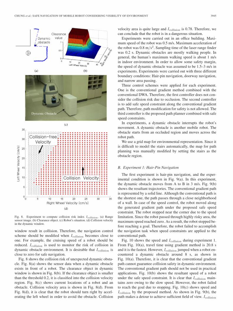
Fig. 8. Experiment to compute collision risk index Icollision. (a) Rangesensor image. (b) Clearance object. (c) Robot’s situation. (d) Collision velocityin the dynamic window.
window result in collision. Therefore, the navigation controlscheme should be modified when Icollision becomes close toone. For example, the cruising speed of a robot should bereduced. Icollision is used to monitor the risk of collision indynamic obstacle environment. It is desirable that Icollision isclose to zero for safe navigation.
Fig. 8 shows the collision risk of unexpected dynamic obsta-cle. Fig. 8(a) shows the sensor data when a dynamic obstacleexists in front of a robot. The clearance object in dynamicwindow is shown in Fig. 8(b). If the clearance object is smallerthan the threshold 0.2, it is classified into the collision velocityregion. Fig. 8(c) shows current locations of a robot and anobstacle. Collision velocity area is shown in Fig. 8(d). FromFig. 8(d), it is clear that the robot should turn right by accel-erating the left wheel in order to avoid the obstacle. Collision
velocity area is quite large and Icollision is 0.78. Therefore, wecan conclude that the robot is in a dangerous situation.
Experiments were carried out in an office building. Maxi-mum speed of the robot was 0.5 m/s. Maximum acceleration ofthe robot was 0.8 m/s2. Sampling time of the laser range finderwas 0.2 s. Dynamic obstacles are mostly walking people. Ingeneral, the human’s maximum walking speed is about 1 m/sin indoor environment. In order to allow some safety margin,the speed of dynamic obstacle was assumed to be 1.5–3 m/s inexperiments. Experiments were carried out with three differentboundary conditions: Hair-pin navigation, doorway navigation,and narrow area passing.
Three control schemes were applied for each experiment.One is the conventional gradient method combined with theconventional DWA. Therefore, the first controller does not con-sider the collision risk due to occlusion. The second controlleris to add safe speed constraint along the conventional gradientpath. Therefore, path modification for safety is not allowed. Thethird controller is the proposed path planner combined with safespeed constraints.
In experiments, a dynamic obstacle interrupts the robot’smovement. A dynamic obstacle is another mobile robot. Theobstacle starts from an occluded region and moves across therobot path.
We use a grid map for environmental representation. Since itis difficult to model the stairs automatically, the map for pathplanning was manually modified by setting the stairs as theobstacle region.
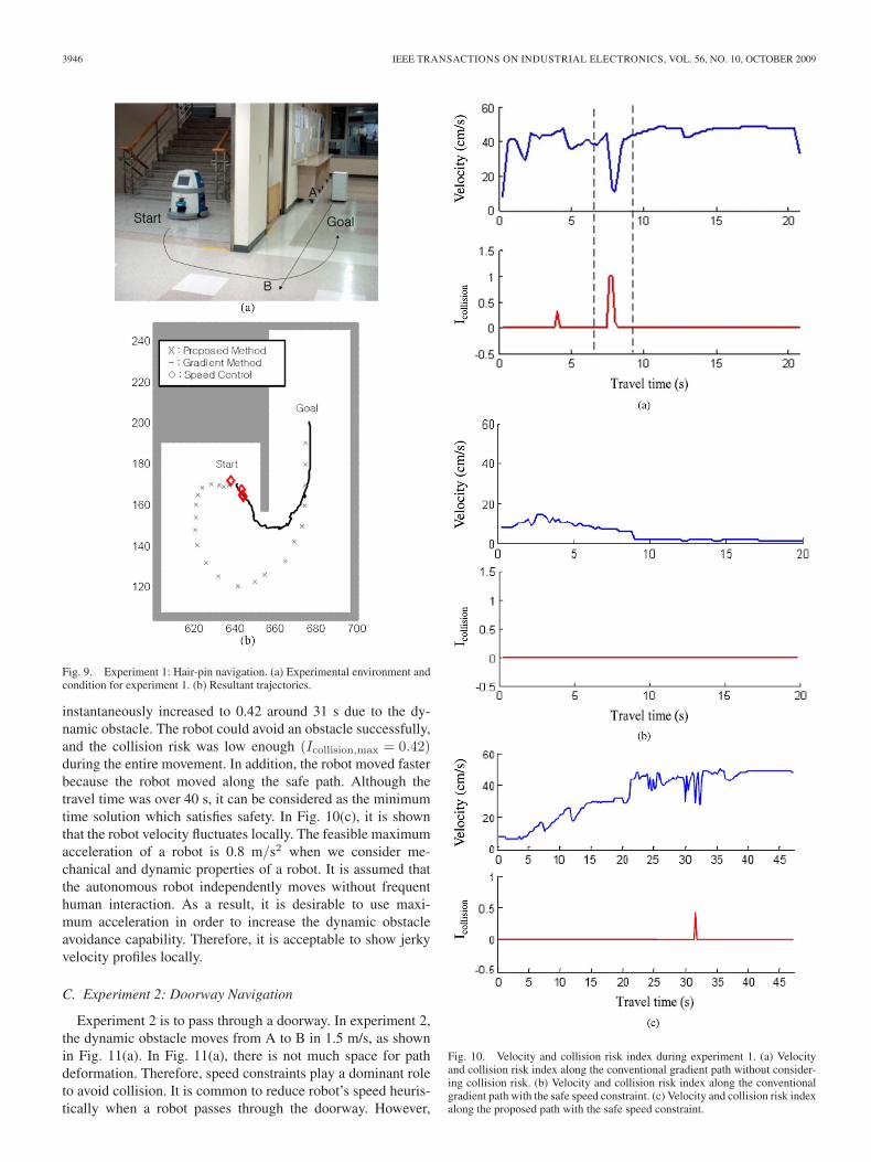
B. Experiment 1: Hair-Pin Navigation
The first experiment is hair-pin navigation, and the exper-imental condition is shown in Fig. 9(a). In this experiment,the dynamic obstacle moves from A to B in 3 m/s. Fig. 9(b)shows the resultant trajectories. The conventional gradient pathis represented by a solid line. Although the conventional path isthe shortest one, the path passes through a close neighborhoodof a wall. In case of the speed control, the robot moved alongthe generated gradient path under the proposed safe speedconstraint. The robot stopped near the corner due to the speedlimitation. Since the robot passed through highly risky area, themaximum speed reached zero. As a result, the robot stopped be-fore reaching a goal. Therefore, the robot failed to accomplishthe navigation task when speed constraints are applied to theconventional path.
Fig. 10 shows the speed and Icollision during experiment 1.From Fig. 10(a), travel time using gradient method is 20.8 sand it is the fastest. However, Icollision jumped when a robot en-countered a dynamic obstacle around 8 s, as shown inFig. 10(a). Therefore, it is clear that the conventional gradientpath cannot guarantee collision safety in dynamic environment.The conventional gradient path should not be used in practicalapplications. Fig. 10(b) shows the resultant speed of a robotunder the safe speed constraint. It is clear that Icollision main-tains zero owing to the slow speed. However, the robot failedto reach the goal due to stopping. Fig. 10(c) shows speed andIcollision by the proposed method. As shown in Fig. 9(b), thepath makes a detour to achieve sufficient field of view. Icollision
3946 IEEE TRANSACTIONS ON INDUSTRIAL ELECTRONICS, VOL. 56, NO. 10, OCTOBER 2009
Fig. 9. Experiment 1: Hair-pin navigation. (a) Experimental environment andcondition for experiment 1. (b) Resultant trajectories.
instantaneously increased to 0.42 around 31 s due to the dy-namic obstacle. The robot could avoid an obstacle successfully,and the collision risk was low enough (Icollision,max = 0.42)during the entire movement. In addition, the robot moved fasterbecause the robot moved along the safe path. Although thetravel time was over 40 s, it can be considered as the minimumtime solution which satisfies safety. In Fig. 10(c), it is shownthat the robot velocity fluctuates locally. The feasible maximumacceleration of a robot is 0.8 m/s2 when we consider me-chanical and dynamic properties of a robot. It is assumed thatthe autonomous robot independently moves without frequenthuman interaction. As a result, it is desirable to use maxi-mum acceleration in order to increase the dynamic obstacleavoidance capability. Therefore, it is acceptable to show jerkyvelocity profiles locally.
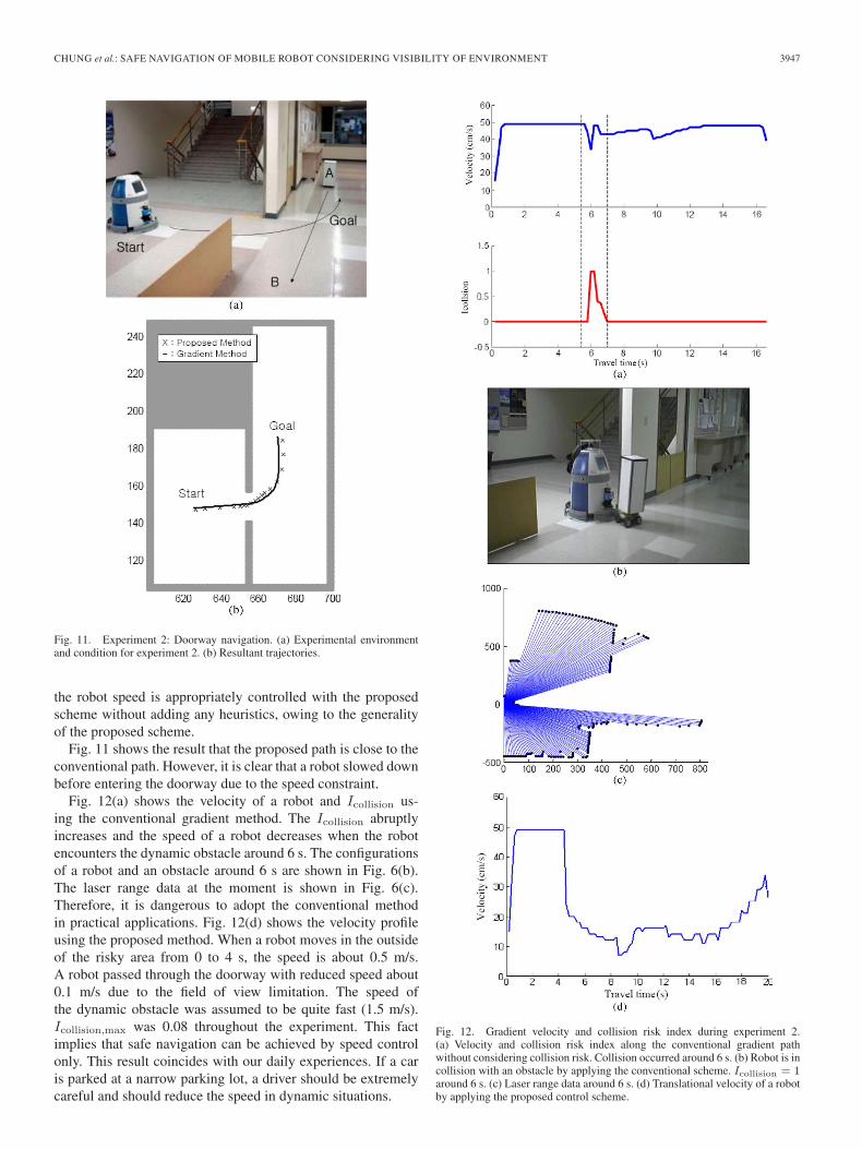
C. Experiment 2: Doorway Navigation
Experiment 2 is to pass through a doorway. In experiment 2,the dynamic obstacle moves from A to B in 1.5 m/s, as shownin Fig. 11(a). In Fig. 11(a), there is not much space for pathdeformation. Therefore, speed constraints play a dominant roleto avoid collision. It is common to reduce robot’s speed heuris-tically when a robot passes through the doorway. However,
Fig. 10. Velocity and collision risk index during experiment 1. (a) Velocityand collision risk index along the conventional gradient path without consider-ing collision risk. (b) Velocity and collision risk index along the conventionalgradient path with the safe speed constraint. (c) Velocity and collision risk indexalong the proposed path with the safe speed constraint.
CHUNG et al.: SAFE NAVIGATION OF MOBILE ROBOT CONSIDERING VISIBILITY OF ENVIRONMENT 3947
Fig. 11. Experiment 2: Doorway navigation. (a) Experimental environmentand condition for experiment 2. (b) Resultant trajectories.
the robot speed is appropriately controlled with the proposedscheme without adding any heuristics, owing to the generalityof the proposed scheme.
Fig. 11 shows the result that the proposed path is close to theconventional path. However, it is clear that a robot slowed downbefore entering the doorway due to the speed constraint.
Fig. 12(a) shows the velocity of a robot and Icollision us-ing the conventional gradient method. The Icollision abruptlyincreases and the speed of a robot decreases when the robotencounters the dynamic obstacle around 6 s. The configurationsof a robot and an obstacle around 6 s are shown in Fig. 6(b).The laser range data at the moment is shown in Fig. 6(c).Therefore, it is dangerous to adopt the conventional methodin practical applications. Fig. 12(d) shows the velocity profileusing the proposed method. When a robot moves in the outsideof the risky area from 0 to 4 s, the speed is about 0.5 m/s.A robot passed through the doorway with reduced speed about0.1 m/s due to the field of view limitation. The speed ofthe dynamic obstacle was assumed to be quite fast (1.5 m/s).Icollision,max was 0.08 throughout the experiment. This factimplies that safe navigation can be achieved by speed controlonly. This result coincides with our daily experiences. If a caris parked at a narrow parking lot, a driver should be extremelycareful and should reduce the speed in dynamic situations.
Fig. 12. Gradient velocity and collision risk index during experiment 2.(a) Velocity and collision risk index along the conventional gradient pathwithout considering collision risk. Collision occurred around 6 s. (b) Robot is incollision with an obstacle by applying the conventional scheme. Icollision = 1around 6 s. (c) Laser range data around 6 s. (d) Translational velocity of a robotby applying the proposed control scheme.
3948 IEEE TRANSACTIONS ON INDUSTRIAL ELECTRONICS, VOL. 56, NO. 10, OCTOBER 2009
Fig. 13. Experiment 3: Passing through narrow area. (a) Experimental envi-ronment and condition for experiment 3. (b) Resultant trajectories.
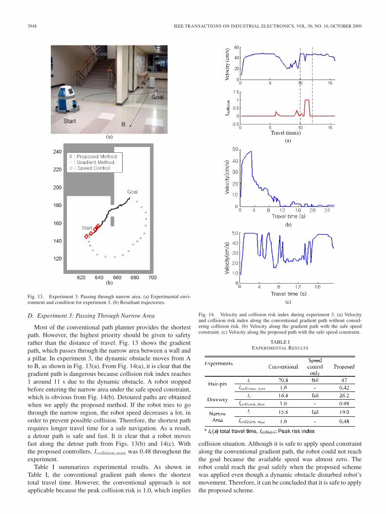
D. Experiment 3: Passing Through Narrow Area
Most of the conventional path planner provides the shortestpath. However, the highest priority should be given to safetyrather than the distance of travel. Fig. 13 shows the gradientpath, which passes through the narrow area between a wall anda pillar. In experiment 3, the dynamic obstacle moves from Ato B, as shown in Fig. 13(a). From Fig. 14(a), it is clear that thegradient path is dangerous because collision risk index reaches1 around 11 s due to the dynamic obstacle. A robot stoppedbefore entering the narrow area under the safe speed constraint,which is obvious from Fig. 14(b). Detoured paths are obtainedwhen we apply the proposed method. If the robot tries to gothrough the narrow region, the robot speed decreases a lot, inorder to prevent possible collision. Therefore, the shortest pathrequires longer travel time for a safe navigation. As a result,a detour path is safe and fast. It is clear that a robot movesfast along the detour path from Figs. 13(b) and 14(c). Withthe proposed controllers, Icollision,max was 0.48 throughout theexperiment.
Table I summarizes experimental results. As shown inTable I, the conventional gradient path shows the shortesttotal travel time. However, the conventional approach is notapplicable because the peak collision risk is 1.0, which implies
Fig. 14. Velocity and collision risk index during experiment 3. (a) Velocityand collision risk index along the conventional gradient path without consid-ering collision risk. (b) Velocity along the gradient path with the safe speedconstraint. (c) Velocity along the proposed path with the safe speed constraint.
TABLE IEXPERIMENTAL RESULTS
collision situation. Although it is safe to apply speed constraintalong the conventional gradient path, the robot could not reachthe goal because the available speed was almost zero. Therobot could reach the goal safely when the proposed schemewas applied even though a dynamic obstacle disturbed robot’smovement. Therefore, it can be concluded that it is safe to applythe proposed scheme.
CHUNG et al.: SAFE NAVIGATION OF MOBILE ROBOT CONSIDERING VISIBILITY OF ENVIRONMENT 3949
IV. CONCLUSION
This paper presented a navigation scheme by consideringthe visibility information for safe and fast navigation. Theenvironmental risks were quantitatively derived to deal withcollision with occluded dynamic obstacles. The collision riskwas quantitatively derived, and it was exploited both for pathplanning and the speed control in a structural way. The pre-sented simulations and experimental results clearly showed thatthe proposed navigation scheme is an efficient and safe solutionfor indoor mobile robots.
REFERENCES
[1] Y. Kanayama, Y. Kimura, F. Miyazaki, and T. Noguchi, “A stable trackingcontrol method for an autonomous mobile robot,” in Proc. IEEE Int. Conf.Robot. Autom., Cincinnati, OH, May 13–18, 1990, pp. 384–389.
[2] K. Macek, I. Petrovic, and R. Siegwart, “A control method for stableand smooth path following of mobile robots,” in Proc. Eur. Conf. MobileRobots, 2005, pp. 128–133.
[3] M. Egerstedt, X. Hu, and A. Stotsky, “Control of mobile platforms usinga virtual vehicle approach,” IEEE Trans. Autom. Control, vol. 46, no. 11,pp. 1777–1782, Nov. 2001.
[4] D. Fox, W. Burgard, and S. Thrun, “The dynamic window approach tocollision avoidance,” IEEE Robot. Autom. Mag., vol. 4, no. 1, pp. 23–33,Mar. 1997.
[5] R. Simmons, “The curvature-velocity method for local obstacle avoid-ance,” in Proc. IEEE Int. Conf. Robot. Autom., Minneapolis, MN,Apr. 22–28, 1996, pp. 3375–3382.
[6] M. Seder and I. Petrovic, “Dynamic window based approach to mobilerobot motion control in the presence of moving obstacles,” in Proc. IEEEInt. Conf. Robot. Autom., Roma, Italy, Apr. 10–14, 2007, pp. 1986–1991.
[7] A. Stentz, “The focusedD∗ algorithm for real-time preplanning,” in Proc.Int. Joint Conf. Artif. Intell., 1995, pp. 1652–1659.
[8] J. Minguez, L. Montano, T. Simeon, and R. Alami, “Global nearnessdiagram navigation (GND),” in Proc. IEEE Int. Conf. Robot. Autom.,Seoul, Korea, May 21–26, 2001, pp. 33–39.
[9] S. Quinlan, “Real-time modification of collision-free paths,” Ph.D.dissertation, Stanford Univ., Stanford, CA, 1994.
[10] L. Montesano, J. Minguez, and L. Montano, “Modeling dynamic sce-narios for local sensor-based motion planning,” Auton. Robots, vol. 25,no. 3, pp. 231–251, Oct. 2008.
[11] M. Sadou, V. Polotski, and P. Cohen, “Occlusions in obstacle de-tection for safe navigation,” in Proc. IEEE Intell. Veh. Symp., 2004,pp. 716–721.
[12] M. Bennewitz, W. Burgard, G. Cielniak, and S. Thrun, “Learning motionpatterns of people for compliant motion,” Int. J. Robot. Res., vol. 24, no. 1,pp. 31–48, 2005.
[13] K. Madhava Krishna, R. Alami, and T. Simeon, “Safe proactive plansand their execution,” Robot. Auton. Syst., vol. 54, no. 3, pp. 244–255,Mar. 2006.
[14] A. Mandow, V. F. Mufloz, R. Fernandez, and A. Garcia-Cerezo, “Dynamicspeed planning for safe navigation,” in Proc. Int. Conf. IROS, 1997,pp. 231–237.
[15] K. Konolige, “A gradient method for realtime robot control,” inProc. IEEE/RSJ Conf. Intell. Robots Syst., Takamatsu, Japan, 2000,pp. 639–646.
[16] S. Kim, W. Chung, C.-B. Moon, and J.-B. Song, “Safe navigation ofa mobile robot using the visibility information,” in Proc. IEEE ICRA,Rome, Italy, Apr. 2007, pp. 1304–1309.
[17] W. Chung, G. Kim, and M. Kim, “Development of the multi-functionalindoor service robot PSR systems,” Auton. Robots, vol. 22, no. 1, pp. 1–17, Mar. 2007.
[18] D. Lee and W. Chung, “Discrete status based localization for indoorservice robots,” IEEE Trans. Ind. Electron., vol. 53, no. 5, pp. 1737–1746,Oct. 2006.
[19] G. Kim and W. Chung, “Tripodal schematic control architecture forintegration of multi-functional indoor service robots,” IEEE Trans. Ind.Electron., vol. 53, no. 5, pp. 1723–1736, Oct. 2006.
[20] J. C. Latombe, Robot Motion Planning. Norwell, MA: Kluwer, 1991.[21] O. Brock and O. Khatib, “High speed navigation using the global
dynamic window approach,” in Proc. Int. Conf. Robot. Autom., 1999,pp. 341–346.
[22] R. C. Luo and K. L. Su, “Multilevel multisensor-based intelligent recharg-ing system for mobile robot,” IEEE Trans. Ind. Electron., vol. 55, no. 1,pp. 270–279, Jan. 2008.
[23] F. J. Berenguer and F. M. Monasterio-Huelin, “Zappa, a quasi-passivebiped walking robot with a tail: Modeling, behavior, and kinematicestimation using accelerometers,” IEEE Trans. Ind. Electron., vol. 55,no. 9, pp. 3281–3289, Sep. 2008.
[24] W. L. Xu, J.-S. Pap, and J. Bronlund, “Design of a biologically inspiredparallel robot for foods chewing,” IEEE Trans. Ind. Electron., vol. 55,no. 2, pp. 832–841, Feb. 2008.
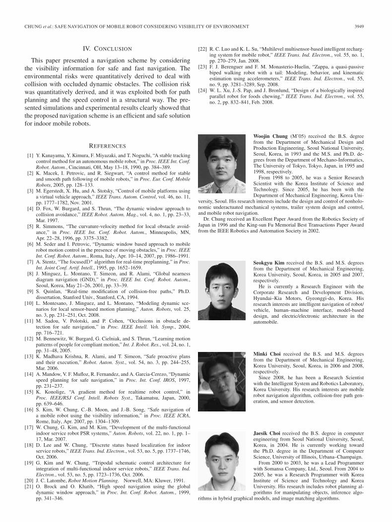
Woojin Chung (M’05) received the B.S. degreefrom the Department of Mechanical Design andProduction Engineering, Seoul National University,Seoul, Korea, in 1993 and the M.S. and Ph.D. de-grees from the Department of Mechano-Informatics,The University of Tokyo, Tokyo, Japan, in 1995 and1998, respectively.
From 1998 to 2005, he was a Senior ResearchScientist with the Korea Institute of Science andTechnology. Since 2005, he has been with theDepartment of Mechanical Engineering, Korea Uni-
versity, Seoul. His research interests include the design and control of nonholo-nomic underactuated mechanical systems, trailer system design and control,and mobile robot navigation.
Dr. Chung received an Excellent Paper Award from the Robotics Society ofJapan in 1996 and the King-sun Fu Memorial Best Transactions Paper Awardfrom the IEEE Robotics and Automation Society in 2002.
Seokgyu Kim received the B.S. and M.S. degreesfrom the Department of Mechanical Engineering,Korea University, Seoul, Korea, in 2005 and 2007,respectively.
He is currently a Research Engineer with theCorporate Research and Development Division,Hyundai–Kia Motors, Gyeonggi-do, Korea. Hisresearch interests are intelligent navigation of robot/vehicle, human–machine interface, model-baseddesign, and electric/electronic architecture in theautomobile.
Minki Choi received the B.S. and M.S. degreesfrom the Department of Mechanical Engineering,Korea University, Seoul, Korea, in 2006 and 2008,respectively.
Since 2008, he has been a Research Scientistwith the Intelligent System and Robotics Laboratory,Korea University. His research interests are mobilerobot navigation algorithm, collision-free path gen-eration, and sensor detection.
Jaesik Choi received the B.S. degree in computerengineering from Seoul National University, Seoul,Korea, in 2004. He is currently working towardthe Ph.D. degree in the Department of ComputerScience, University of Illinois, Urbana–Champaign.
From 2000 to 2003, he was a Lead Programmerwith Somansa Company, Ltd., Seoul. From 2004 to2005, he was a Research Programmer with KoreaInstitute of Science and Technology and KoreaUniversity. His research includes robot planning al-gorithms for manipulating objects, inference algo-
rithms in hybrid graphical models, and image matching algorithms.
3950 IEEE TRANSACTIONS ON INDUSTRIAL ELECTRONICS, VOL. 56, NO. 10, OCTOBER 2009
Hoyeon Kim received the B.S. degree from theDepartment of Mechanical Engineering, Korea Uni-versity, Seoul, Korea, in 2008, where he is currentlyworking toward the M.S. degree in robotics.
His research interests are mobile robot navigation,human robot interaction, and human following.
Chang-bae Moon received the B.S. and M.S. de-grees from the School of Mechanical Engineering,Korea University, Seoul, Korea, in 2006 and 2008,respectively, where he is currently working towardthe Ph.D. degree.
His research interests include mobile robot motioncontrol, path planning, localization, and behaviorselection.
Jae-Bok Song (M’00) received the B.S. and M.S. de-grees in mechanical engineering from Seoul NationalUniversity, Seoul, Korea, in 1983 and 1985, respec-tively, and the Ph.D. degree in mechanical engineer-ing from the Massachusetts Institute of Technology,Cambridge, in 1992.
In 1993, he joined the faculty of the Departmentof Mechanical Engineering, Korea University, Seoul,where he has been an Full Professor since 2002.Currently, he is the Director with the IntelligentRobotics Research Center, Korea University. His
current research interests are safe manipulators, robot navigation, and designand control of the robotic systems including haptic devices and field robots.
Dr. Song is an Editor of International Journal of Control, Automation, andSystems.