s25fl032p - spansion
TRANSCRIPT
S25FL032P
32-Mbit 3.0 V Flash Memory
Cypress Semiconductor Corporation • 198 Champion Court • San Jose, CA 95134-1709 • 408-943-2600Document Number: 002-00650 Rev. *L Revised May 19, 2017
This product family has been retired and is not recommended for designs. For new and current designs, S25FL064L supersede S25FL032P. These are the factory-recommended migration paths. Refer to the S25FL-L Family datasheets for specifications and ordering information.
Distinctive CharacteristicsArchitectural Advantages Single power supply operation
– Full voltage range: 2.7 V to 3.6 V read and write operations
Memory architecture– Uniform 64-KB sectors
– Top or bottom parameter block (two 64-KB sectors (top or bottom) broken down into 16 4-KB sub-sectors each)
– 256-byte page size– Backward compatible with the S25FL032A device
Program – Page Program (up to 256 bytes) in 1.5 ms (typical)– Program operations are on a page by page basis– Accelerated programming mode via 9-V W#/ACC pin– Quad Page Programming
Erase– Bulk erase function – Sector erase (SE) command (D8h) for 64-KB sectors– Sub-sector erase (P4E) command (20h) for 4-KB sectors– Sub-sector erase (P8E) command (40h) for 8-KB sectors
Cycling endurance– 100,000 cycles per sector typical
Data retention– 20 years typical
Device ID– JEDEC standard two-byte electronic signature– RES command one-byte electronic signature for backward
compatibility
One time programmable (OTP) area for permanent, secure identification; can be programmed and locked at the factory or by the customer
Common Flash Interface (CFI) compliant: allows host system to identify and accommodate multiple flash devices
Process technology– Manufactured on 0.09 m MirrorBit® process technology
Package option– Industry Standard Pinouts– 8-pin SO package (208 mils)– 16-pin SO package (300 mils)– 8-contact USON package (5 6 mm)– 8-contact WSON package (6 8 mm)– 24-ball BGA 6 8 mm package, 5 5 pin configuration– 24-ball BGA 6 8 mm package, 6 4 pin configuration
Performance Characteristics Speed
– Normal READ (Serial): 40-MHz clock rate– FAST_READ (Serial): 104-MHz clock rate (maximum)– DUAL I/O FAST_READ: 80-MHz clock rate or
20 MB/s effective data rate– QUAD I/O FAST_READ: 80 MHz clock rate or
40 MB/s effective data rate
Power saving standby mode– Standby Mode 80 A (typical)– Deep Power-Down Mode 3 A (typical)
Memory Protection Features Memory protection
– W#/ACC pin works in conjunction with Status Register Bits to protect specified memory areas
– Status Register Block Protection bits (BP2, BP1, BP0) in status register configure parts of memory as read-only
Not Rec
ommen
ded f
or New
Des
ign

Document Number: 002-00650 Rev. *L Page 2 of 60
S25FL032P
General DescriptionThe S25FL032P is a 3.0 V (2.7 V to 3.6 V), single-power-supply Flash memory device. The device consists of 64 uniform 64-KB sectors with the two (top or bottom) 64-KB sectors further split up into thirty-two 4-KB sub sectors. The S25FL032P device is fully backward compatible with the S25FL032A device.
The device accepts data written to Serial Input (SI) and outputs data on Serial Output (SO). The devices are designed to be programmed in-system with the standard system 3.0-V VCC supply.
The S25FL032P device adds the following high-performance features using five new instructions:
Dual Output Read using both SI and SO pins as output pins at a clock rate of up to 80 MHz
Quad Output Read using SI, SO, W#/ACC, and HOLD# pins as output pins at a clock rate of up to 80 MHz
Dual I/O High Performance Read using both SI and SO pins as input and output pins at a clock rate of up to 80 MHz
Quad I/O High Performance Read using SI, SO, W#/ACC, and HOLD# pins as input and output pins at a clock rate of up to 80 MHz
Quad Page Programming using SI, SO, W#/ACC, and HOLD# pins as input pins to program data at a clock rate of up to 80 MHz
The memory can be programmed 1 to 256 bytes at a time, using the Page Program command. The device supports Sector Erase and Bulk Erase commands.
Each device requires only a 3.0-V power supply (2.7 V to 3.6 V) for both read and write functions. Internally generated and regulated voltages are provided for the program operations. This device requires a high voltage supply to the W#/ACC pin to enable the Accelerated Programming mode.
The S25FL032P device also offers a One-Time Programmable area (OTP) of up to 128 bits (16 bytes) for permanent secure identification and an additional 490 bytes of OTP space for other use. This OTP area can be programmed or read using the OTPP or OTPR instructions.
Not Rec
ommen
ded f
or New
Des
ign

Document Number: 002-00650 Rev. *L Page 3 of 60
S25FL032P
Contents1. Block Diagram.............................................................. 4
2. Connection Diagrams.................................................. 5
3. Input/Output Descriptions........................................... 7
4. Logic Symbol ............................................................... 7
5. Ordering Information ................................................... 85.1 Valid Combinations ........................................................ 9
6. SPI Modes................................................................... 10
7. Device Operations ..................................................... 117.1 Byte or Page Programming.......................................... 117.2 Quad Page Programming ............................................ 117.3 Dual and Quad I/O Mode ............................................. 117.4 Sector Erase / Bulk Erase............................................ 117.5 Monitoring Write Operations
Using the Status Register ............................................ 117.6 Active Power and Standby Power Modes.................... 117.7 Status Register ............................................................ 127.8 Configuration Register ................................................. 127.9 Data Protection Modes ................................................ 137.10 Hold Mode (HOLD#) .................................................... 147.11 Accelerated Programming Operation........................... 15
8. Sector Address Table ................................................ 16
9. Command Definitions................................................ 189.1 Read Data Bytes (READ) ............................................ 209.2 Read Data Bytes at Higher Speed
(FAST_READ) ............................................................. 209.3 Dual Output Read Mode (DOR)................................... 219.4 Quad Output Read Mode (QOR) ................................. 219.5 DUAL I/O High Performance Read
Mode (DIOR)................................................................ 229.6 Quad I/O High Performance Read
Mode (QIOR) ............................................................... 239.7 Read Identification (RDID) ........................................... 259.8 Read-ID (READ_ID)..................................................... 289.9 Write Enable (WREN) .................................................. 299.10 Write Disable (WRDI)................................................... 299.11 Read Status Register (RDSR) ..................................... 309.12 Read Configuration Register (RCR) ............................ 319.13 Write Registers (WRR) ................................................ 329.14 Page Program (PP)...................................................... 339.15 QUAD Page Program (QPP) ....................................... 359.16 Parameter Sector Erase (P4E, P8E) ........................... 369.17 Sector Erase (SE) ........................................................ 379.18 Bulk Erase (BE) ........................................................... 37
9.19 Deep Power-Down (DP) ............................................... 389.20 Release from Deep Power-Down (RES)....................... 399.21 Clear Status Register (CLSR)....................................... 409.22 OTP Program (OTPP)................................................... 409.23 Read OTP Data Bytes (OTPR)..................................... 40
10. OTP Regions ............................................................... 4110.1 Programming OTP Address Space............................... 4110.2 Reading OTP Data ....................................................... 4110.3 Locking OTP Regions................................................... 42
11. Power-up and Power-down........................................ 44
12. Initial Delivery State.................................................... 45
13. Program Acceleration via W#/ACC Pin ..................... 45
14. Electrical Specifications............................................. 4614.1 Absolute Maximum Ratings .......................................... 46
15. Operating Ranges ....................................................... 47
16. DC Characteristics...................................................... 47
17. Test Conditions ........................................................... 48
18. AC Characteristics...................................................... 4918.1 Capacitance.................................................................. 50
19. Physical Dimensions .................................................. 5219.1 SOC008 wide — 8-pin Plastic Small
Outline Package (208-mils Body Width) ....................... 5219.2 SO3 016 — 16-pin Wide Plastic Small
Outline Package (300-mils Body Width) ....................... 5319.3 UNE008 — USON 8-contact (5 x 6 mm)
No-Lead Package ......................................................... 5419.4 WNF008 — WSON 8-contact (6 x 8 mm)
No-Lead Package ......................................................... 5519.5 FAB024 — 24-ball Ball Grid Array
(6 x 8 mm) Package...................................................... 5619.6 FAC024 — 24-ball Ball Grid Array
(6 x 8 mm) Package...................................................... 57
20. Revision History.......................................................... 58Document History Page ..................................................... 58Sales, Solutions, and Legal Information .......................... 60
Worldwide Sales and Design Support ...........................60Products ........................................................................60PSoC® Solutions ..........................................................60Cypress Developer Community .....................................60Technical Support .........................................................60
Not Rec
ommen
ded f
or New
Des
ign

Document Number: 002-00650 Rev. *L Page 4 of 60
S25FL032P
1. Block Diagram
SRAM PS
Logic
Array - L Array - R
RD DATA PATH
IO
XDEC
CS
#
SC
K
SI /
IO0
SO
/ IO
1
GN
D
HO
LD#
/ IO
3
VC
C
W#
/ AC
C /
IO2
Not Rec
ommen
ded f
or New
Des
ign

Document Number: 002-00650 Rev. *L Page 5 of 60
S25FL032P
2. Connection DiagramsFigure 1. 16-pin Plastic Small Outline Package (SO)
NoteDNC = Do Not Connect (Reserved for future use)
Figure 2. 8-pin Plastic Small Outline Package (SO)
Figure 3. 8-contact USON (5 x 6 mm) Package
NoteThere is an exposed central pad on the underside of the USON package. This should not be connected to any voltage or signal line on the PCB. Connecting the central pad to GND (VSS) is possible, provided PCB routing ensures 0mV difference between voltage at the USON GND (VSS) lead and the central exposed pad.
Figure 4. 8-contact WSON Package (6 x 8 mm)
NoteThere is an exposed central pad on the underside of the WSON package. This should not be connected to any voltage or signal line on the PCB. Connecting the central pad to GND (VSS) is possible, provided PCB routing ensures 0mV difference between voltage at the WSON GND (VSS) lead and the central exposed pad.
1
2
3
4
16
15
14
13
HOLD#/IO3
VCC
DNC
DNC DNC
DNC
SI/IO0
SCK
5
6
7
8
12
11
10
9 W#/ACC/IO2
GND
DNC
DNCDNC
DNC
CS#
SO/IO1
1
2
3
4
CS#
SO/IO1
W#/ACC/IO2
GND SI/IO0
SCK
HOLD#/IO3
VCC
5
6
7
8
1
2
3
4 5
6
7
8 CS#
SO/IO1 HOLD#/IO3
SCK
SI/IO0 GND
USON
W#/ACC/IO2
VCC
1
2
3
4 5
6
7
8 CS#
SO/IO1 HOLD#/IO3
SCK
SI/IO0 GND
WSON
W#/ACC/IO2
VCC
Not Rec
ommen
ded f
or New
Des
ign

Document Number: 002-00650 Rev. *L Page 6 of 60
S25FL032P
Figure 5. 6x8 mm 24-ball BGA Package, 5x5 Pin Configuration
Figure 6. 6x8 mm 24-ball BGA Package, 6x4 Pin Configuration
SCK
NC
NC
GND VCC NC
B2 B3 B4 B5
CS# NC W#/ACC/IO2 NC
C1 C2 C3 C4 C5
SO/IO1 SI/IO0 HOLD#/IO3 NC
D1 D2 D3 D4 D5
NC NC NC
E1 E2 E3
NC NC
E4 E5
NC NC NC NC
A2 A3 A4 A5
B1
NC
SCK
NC
NC
GND VCC
B2 B3 B4
CS# NC W#/ACC/IO2
C1 C2 C3 C4
SO/IO1 SI/IO0 HOLD#/IO3
D1 D2 D3 D4
NC NC NC
E1 E2 E3
NC
E4
NC NC NC
A2 A3 A4
B1
NC
NC NC NC
F1 F2 F3
NC
F4
NC
A1
Not Rec
ommen
ded f
or New
Des
ign
Document Number: 002-00650 Rev. *L Page 7 of 60
S25FL032P
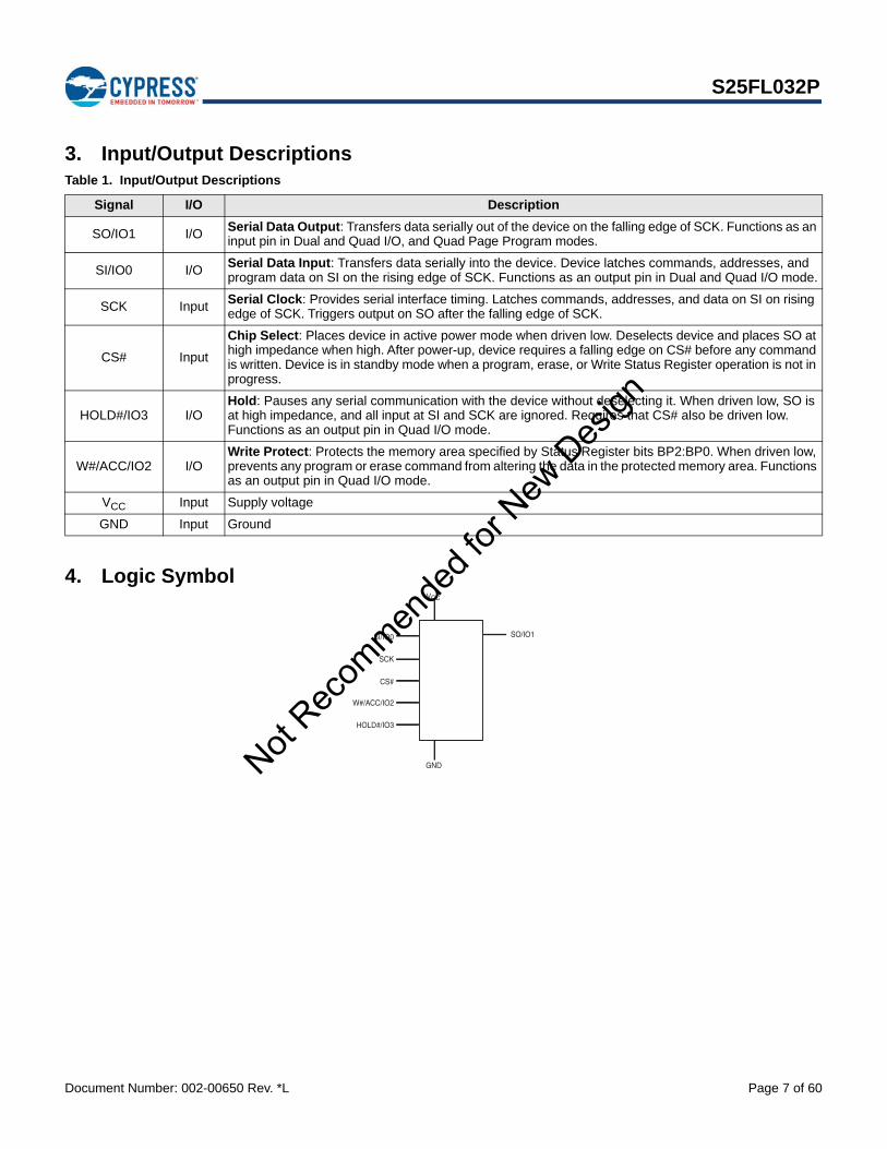
3. Input/Output Descriptions
4. Logic Symbol
Table 1. Input/Output Descriptions
Signal I/O Description
SO/IO1 I/O Serial Data Output: Transfers data serially out of the device on the falling edge of SCK. Functions as an input pin in Dual and Quad I/O, and Quad Page Program modes.
SI/IO0 I/OSerial Data Input: Transfers data serially into the device. Device latches commands, addresses, and program data on SI on the rising edge of SCK. Functions as an output pin in Dual and Quad I/O mode.
SCK Input Serial Clock: Provides serial interface timing. Latches commands, addresses, and data on SI on rising edge of SCK. Triggers output on SO after the falling edge of SCK.
CS# Input
Chip Select: Places device in active power mode when driven low. Deselects device and places SO at high impedance when high. After power-up, device requires a falling edge on CS# before any command is written. Device is in standby mode when a program, erase, or Write Status Register operation is not in progress.
HOLD#/IO3 I/OHold: Pauses any serial communication with the device without deselecting it. When driven low, SO is at high impedance, and all input at SI and SCK are ignored. Requires that CS# also be driven low. Functions as an output pin in Quad I/O mode.
W#/ACC/IO2 I/OWrite Protect: Protects the memory area specified by Status Register bits BP2:BP0. When driven low, prevents any program or erase command from altering the data in the protected memory area. Functions as an output pin in Quad I/O mode.
VCC Input Supply voltage
GND Input Ground
CS#
SO/IO1
W#/ACC/IO2
GND
SI/IO0
SCK
HOLD#/IO3
VCC
Not Rec
ommen
ded f
or New
Des
ign

Document Number: 002-00650 Rev. *L Page 8 of 60
S25FL032P
5. Ordering InformationThe ordering part number is formed by a valid combination of the following:
S25FL 032 P 0X M F I 00 1Packing Type0 = Tray 1 = Tube3 = 13” Tape and Reel
Model Number (Additional Ordering Options)03 = 6 x 4 pin configuration BGA package02 = 5 x 5 pin configuration BGA package01 = 8-pin SO package / 8-contact USON package00 = 16-pin SO package / 8-contact WSON package
Temperature RangeI = Industrial (–40°C to +85°C)V = Automotive In-cabin (–40°C to +105°C)A = Automotive, AEC-Q100 Grade 3 (–40°C to +85°C)B = Automotive, AEC-Q100 Grade 2 (–40°C to +105°C)
Package MaterialsF = Lead (Pb)-freeH = Low-Halogen, Lead (Pb)-free
Package TypeM = 8-pin / 16-pin SO packageN = 8-contact USON / WSON packageB = 24-ball BGA 6 x 8 mm package, 1.00 mm pitch
Speed0X = 104 MHz
Device TechnologyP = 0.09 µm MirrorBit® Process Technology
Density032 = 32 Mbit
Device FamilyS25FLCypress Memory 3.0 V-only, Serial Peripheral Interface (SPI) Flash Memory
Not Rec
ommen
ded f
or New
Des
ign

Document Number: 002-00650 Rev. *L Page 9 of 60
S25FL032P
5.1 Valid CombinationsValid Combinations — Standard
Table 2 lists the valid combinations configurations planned to be supported in volume for this device.
Valid Combinations — Automotive Grade / AEC-Q100Table 3 lists configurations that are Automotive Grade / AEC-Q100 qualified and are planned to be available in volume. The table will be updated as new combinations are released. Consult your local sales representative to confirm availability of specific combinations and to check on newly released combinations.
Production Part Approval Process (PPAP) support is only provided for AEC-Q100 grade products.
Products to be used in end-use applications that require ISO/TS-16949 compliance must be AEC-Q100 grade products in combination with PPAP. Non–AEC-Q100 grade products are not manufactured or documented in full compliance with ISO/TS-16949 requirements.
AEC-Q100 grade products are also offered without PPAP support for end-use applications that do not require ISO/TS-16949 compliance.
Table 2. S25FL032P Valid Combinations
Base Ordering Part Number Speed Option Package and
TemperatureModel
Number Packing Type Package Marking
S25FL032P 0X
MFI, NFI00, 01 0, 1, 3
FL032P + (Temp) + FMFV, NFV
BHI02, 03 0, 3
BHV
Table 3. S25FL032P Valid Combinations — Automotive Grade / AEC-Q100
Base Ordering Part Number Speed Option Package and
TemperatureModel
Number Packing Type Package Marking
S25FL032P 0X
MFA,NFA00, 01 0, 1, 3
FL032P + (Temp) + FMFB, NFB
BHA, BHB 02, 03 0, 3
Not Rec
ommen
ded f
or New
Des
ign

Document Number: 002-00650 Rev. *L Page 10 of 60
S25FL032P
6. SPI ModesA microcontroller can use either of its two SPI modes to control Cypress SPI Flash memory devices:
CPOL = 0, CPHA = 0 (Mode 0)
CPOL = 1, CPHA = 1 (Mode 3)
Input data is latched in on the rising edge of SCK, and output data is available from the falling edge of SCK for both modes.
When the bus master is in standby mode, SCK is as shown in Figure 8 for each of the two modes:
SCK remains at 0 for (CPOL = 0, CPHA = 0 Mode 0)
SCK remains at 1 for (CPOL = 1, CPHA = 1 Mode 3)
Figure 7. Bus Master and Memory Devices on the SPI Bus
NoteThe Write Protect/Accelerated Programming (W#/ACC) and Hold (HOLD#) signals should be driven high (logic level 1) or low (logic level 0) as appropriate.
Figure 8. SPI Modes Supported
SPI Interface with (CPOL, CPHA) =
(0, 0) or (1, 1)
Bus Master
CS3 CS2 CS1
SPI Memory Device
SPI Memory Device
SPI Memory Device
CS# HOLD#CS# HOLD#CS# HOLD#
SCK SO SI SCK SO SI SCK SO SI
SO
SI
SCK
W#/ACC W#/ACC W#/ACC
MSB
MSB
SCK
SCK
SI
SO
CPHACPOL
0 0
1 1
CS#
Mode 0
Mode 3 Not Rec
ommen
ded f
or New
Des
ign

Document Number: 002-00650 Rev. *L Page 11 of 60
S25FL032P
7. Device OperationsAll Cypress SPI devices accept and output data in bytes (8 bits at a time). The SPI device is a slave device that supports an inactive clock while CS# is held low.
7.1 Byte or Page ProgrammingProgramming data requires two commands: Write Enable (WREN), which is one byte, and a Page Program (PP) sequence, which consists of four bytes plus data. The Page Program sequence accepts from 1 byte up to 256 consecutive bytes of data (which is the size of one page) to be programmed in one operation. Programming means that bits can either be left at 0, or programmed from 1 to 0. Changing bits from 0 to 1 requires an erase operation.
7.2 Quad Page ProgrammingThe Quad Page Program (QPP) instruction allows up to 256 bytes of data to be programmed using 4 pins as inputs at the same time, thus effectively quadrupling the data transfer rate, compared to the Page Program (PP) instruction. The Write Enable Latch (WEL) bit must be set to a 1 using the Write Enable (WREN) command prior to issuing the QPP command.
7.3 Dual and Quad I/O Mode The S25FL032P device supports Dual and Quad I/O operation when using the Dual/Quad Output Read Mode and the Dual/Quad I/O High Performance Mode instructions. Using the Dual or Quad I/O instructions allows data to be transferred to or from the device at two to four times the rate of standard SPI devices. When operating in the Dual or Quad I/O High Performance Mode (BBh or EBh instructions), data can be read at fast speed using two or four data bits at a time, and the 3-byte address can be input two or four address bits at a time.
7.4 Sector Erase / Bulk EraseThe Sector Erase (SE) and Bulk Erase (BE) commands set all the bits in a sector or the entire memory array to 1. While bits can be individually programmed from 1 to 0, erasing bits from 0 to 1 must be done on a sector-wide (SE) or array-wide (BE) level. In addition to the 64-KB Sector Erase (SE), the S25FL032P device also offers 4-KB Parameter Sector Erase (P4E) and 8-KB Parameter Sector Erase (P8E).
7.5 Monitoring Write Operations Using the Status RegisterThe host system can determine when a Write Register, program, or erase operation is complete by monitoring the Write in Progress (WIP) bit in the Status Register. The Read from Status Register command provides the state of the WIP bit. In addition, the S25FL032P device offers two additional bits in the Status Register (P_ERR, E_ERR) to indicate whether a Program or Erase operation was a success or failure.
7.6 Active Power and Standby Power ModesThe device is enabled and in the Active Power mode when Chip Select (CS#) is Low. When CS# is high, the device is disabled, but may still be in the Active Power mode until all program, erase, and Write Registers operations have completed. The device then goes into the Standby Power mode, and power consumption drops to ISB. The Deep Power-Down (DP) command provides additional data protection against inadvertent signals. After writing the DP command, the device ignores any further program or erase commands, and reduces its power consumption to IDP.
Not Rec
ommen
ded f
or New
Des
ign

Document Number: 002-00650 Rev. *L Page 12 of 60
S25FL032P
7.7 Status RegisterThe Status Register contains the status and control bits that can be read or set by specific commands (see Table 10 on page 18). These bits configure different protection configurations and supply information of operation of the device. (for details see Table 17 on page 30):
Write In Progress (WIP): Indicates whether the device is performing a Write Registers, program or erase operation.
Write Enable Latch (WEL): Indicates the status of the internal Write Enable Latch.
Block Protect (BP2, BP1, BP0): Nonvolatile bits that define memory area to be software-protected against program and erase commands.
Erase Error (E_ERR): The Erase Error Bit is used as an Erase operation success and failure check.
Program Error (P_ERR): The Program Error Bit is used as an program operation success and failure check.
Status Register Write Disable (SRWD): Places the device in the Hardware Protected mode when this bit is set to 1 and the W#/ACC input is driven low. In this mode, the non-volatile bits of the Status Register (SRWD, BP2, BP1, BP0) become read-only bits.
7.8 Configuration RegisterThe Configuration Register contains the control bits that can be read or set by specific commands. These bits configure different configurations and security features of the device.
The FREEZE bit locks the BP2-0 bits in Status Register and the TBPROT and TBPARM bits in the Configuration Register. Note that once the FREEZE bit has been set to ‘1’, then it cannot be cleared to ‘0’ until a power-on-reset is executed. As long as the FREEZE bit is set to ‘0’, then the other bits of the Configuration Register, including FREEZE bit, can be written to.
The QUAD bit is nonvolatile and sets the pin out of the device to Quad mode; that is, W#/ACC becomes IO2 and HOLD# becomes IO3. The instructions for Serial, Dual Output, and Dual I/O reads function as normal. The W#/ACC and HOLD# functionality does not work when the device is set in Quad mode.
The TBPARM bit defines the logical location of the 4 KB parameter sectors. The parameter sectors consist of thirty two 4 KB sectors. All sectors other than the parameter sectors are defined to be 64-KB uniform in size. When TBPARM is set to a ‘1’, the 4-KB parameter sectors starts at the top of the array. When TBPARM is set to a ‘0’, the 4-KB parameter sectors starts at the bottom of the array. Note that once this bit is set to a '1', it cannot be changed back to '0'.
The BPNV bit defines whether or not the BP2-0 bits in the Status Register are volatile or non-volatile. When BPNV is set to a ‘1’, the BP2-0 bits in the Status Register are volatile and will be reset to binary 111 after power on reset. When BPNV is set to a ‘0’, the BP2-0 bits in the Status Register are non-volatile. Note that once this bit is set to a '1', it cannot be changed back to '0'.
The TBPROT bit defines the operation of the block protection bits BP2, BP1, and BP0 in the Status Register. When TBPROT is set to a ‘0’, then the block protection is defined to start from the top of the array. When TBPROT is set to a ‘1’, then the block protection is defined to start from the bottom of the array. Note that once this bit is set to a '1', it cannot be changed back to '0'.
Note: It is suggested that the Block Protection and Parameter sectors not be set to the same area of the array; otherwise, the user cannot utilize the Parameter sectors if they are protected. The following matrix shows the recommended settings.
Table 4. Suggested Cross Settings
TBPARM TBPROT Array Overview
0 0Parameter Sectors – BottomBP Protection – Top(default)
0 1 Not recommended (Parameters & BP Protection are both Bottom)
1 0 Not recommended (parameters & BP Protection are both Top)
1 1 Parameter Sectors - Top of Array (high address)BP Protection - Bottom of Array (low address)
Not Rec
ommen
ded f
or New
Des
ign

Document Number: 002-00650 Rev. *L Page 13 of 60
S25FL032P
Note(Default) indicates the value of each Configuration Register bit set upon initial factory shipment.
7.9 Data Protection ModesCypress SPI Flash memory devices provide the following data protection methods:
The Write Enable (WREN) command: Must be written prior to any command that modifies data. The WREN command sets the Write Enable Latch (WEL) bit. The WEL bit resets (disables writes) on power-up or after the device completes the following commands:
– Page Program (PP)
– Sector Erase (SE)
– Bulk Erase (BE)
– Write Disable (WRDI)
– Write Register (WRR)
– Parameter 4 KB Sector Erase (P4E)
– Parameter 8 KB Sector Erase (P8E)
– Quad Page Programming (QPP)
– OTP Byte Programming (OTPP)
Software Protected Mode (SPM): The Block Protect (BP2, BP1, BP0) bits define the section of the memory array that can be read but not programmed or erased. Table 6 and Table 7 shows the sizes and address ranges of protected areas that are defined by Status Register bits BP2:BP0.
Hardware Protected Mode (HPM): The Write Protect (W#/ACC) input and the Status Register Write Disable (SRWD) bit together provide write protection.
Clock Pulse Count: The device verifies that all program, erase, and Write Register commands consist of a clock pulse count that is a multiple of eight before executing them.
Table 5. Configuration Register Table
Bit Bit Name Bit Function Description
7 NA Not Used
6 NA Not Used
5 TBPROT Configures start of block protection 1 = Bottom Array (low address)0 = Top Array (high address) (Default)
4 NA Do not use
3 BPNVConfigures BP2-0 bits in the Status Register
1 = Volatile0 = Nonvolatile (Default)
2 TBPARM Configures Parameter sector location 1 = Top Array (high address)0 = Bottom Array (low address) (Default)
1 QUAD Puts the device into Quad I/O mode 1 = Quad I/O0 = Dual or Serial I/O (Default)
0 FREEZELocks BP2-0 bits in the Status Register
1 = Enabled0 = Disabled (Default)
Not Rec
ommen
ded f
or New
Des
ign

Document Number: 002-00650 Rev. *L Page 14 of 60
S25FL032P
7.10 Hold Mode (HOLD#)The Hold input (HOLD#) stops any serial communication with the device, but does not terminate any Write Registers, program or erase operation that is currently in progress.
The Hold mode starts on the falling edge of HOLD# if SCK is also low (see Figure 9, standard use). If the falling edge of HOLD# does not occur while SCK is low, the Hold mode begins after the next falling edge of SCK (non-standard use).
The Hold mode ends on the rising edge of HOLD# signal (standard use) if SCK is also low. If the rising edge of HOLD# does not occur while SCK is low, the Hold mode ends on the next falling edge of CLK (non-standard use) See Figure 9.
The SO output is high impedance, and the SI and SCK inputs are ignored (don’t care) for the duration of the Hold mode.
CS# must remain low for the entire duration of the Hold mode to ensure that the device internal logic remains unchanged. If CS# goes high while the device is in the Hold mode, the internal logic is reset. To prevent the device from reverting to the Hold mode when device communication is resumed, HOLD# must be held high, followed by driving CS# low.
Note: The HOLD Mode feature is disabled during Quad I/O Mode.
Table 6. TBPROT = 0 (Starts Protection from TOP of Array)
Status Register Block Memory Array Protected Portion of
Total Memory Area
BP2 BP1 BP0 ProtectedAddress Range
Protected Sectors
UnprotectedAddress Range
UnprotectedSectors
0 0 0 None 0 000000h-3FFFFFh SA63:SA0 0
0 0 1 3F0000h-3FFFFFh (1) SA63 000000h-3EFFFFh SA62:SA0 1/64
0 1 0 3E0000h-3FFFFFh (2) SA63:SA62 000000h-3DFFFFh SA61:SA0 1/32
0 1 1 3C0000h-3FFFFFh (4) SA63:SA60 000000h-3BFFFFh SA59:SA0 1/16
1 0 0 380000h-3FFFFFh (8) SA63:SA56 000000h-37FFFFh SA55:SA0 1/8
1 0 1 300000h-3FFFFFh (16) SA63:SA48 000000h-2FFFFFh SA47:SA0 1/4
1 1 0 200000h-3FFFFFh (32) SA63:SA32 000000h-1FFFFFh SA31:SA0 1/2
1 1 1 000000h-3FFFFFh (64) SA63:SA0 None None All
Table 7. TBPROT=1 (Starts Protection from BOTTOM of Array)
Status Register Block Memory Array Protected Portion of
Total Memory Area
BP2 BP1 BP0 ProtectedAddress Range
Protected Sectors
UnprotectedAddress Range
UnprotectedSectors
0 0 0 None 0 000000h-3FFFFFh SA0:SA63 0
0 0 1 000000h-00FFFFh (1) SA0 010000h-3FFFFFh SA1:SA63 1/64
0 1 0 000000h-01FFFFh (2) SA0:SA1 020000h-3FFFFFh SA2:SA63 1/32
0 1 1 000000h-03FFFFh (4) SA0:SA3 040000h-3FFFFFh SA4:SA63 1/16
1 0 0 000000h-07FFFFh (8) SA0:SA7 080000h-3FFFFFh SA8:SA63 1/8
1 0 1 000000h-0FFFFFh (16) SA0:SA15 100000h-3FFFFFh SA16:SA63 1/4
1 1 0 000000h-1FFFFFh (32) SA0:SA31 200000h-3FFFFFh SA32:SA63 1/2
1 1 1 000000h-3FFFFFh (64) SA0:SA63 None None ALL
Not Rec
ommen
ded f
or New
Des
ign

Document Number: 002-00650 Rev. *L Page 15 of 60
S25FL032P
Figure 9. Hold Mode Operation
7.11 Accelerated Programming OperationThe device offers accelerated program operations through the ACC function. This function is primarily intended to allow faster manufacturing throughput at the factory. If the system asserts VHH on this pin, the device uses the higher voltage on the pin to reduce the time required for program operations. Removing VHH from the W#/ACC pin returns the device to normal operation. Note that the W#/ACC pin must not be at VHH for operations other than accelerated programming, or device damage may result. In addition, the W#/ACC pin must not be left floating or unconnected; inconsistent behavior of the device may result.
Note: The ACC function is disabled during Quad I/O Mode.
SCK
HOLD#
HoldCondition
(standard use)
HoldCondition
(non-standard use)
Not Rec
ommen
ded f
or New
Des
ign

Document Number: 002-00650 Rev. *L Page 16 of 60
S25FL032P
8. Sector Address TableThe Sector Address tables show the size of the memory array, sectors, and pages. The device uses pages to cache the program data before the data is programmed into the memory array. Each page or byte can be individually programmed (bits are changed from 1 to 0). The data is erased (bits are changed from 0 to 1) on a sub-sector, sector- or device-wide basis using the P4E/P8E, SE or BE commands. Table 8 and Table 9 show the starting and ending address for each sector. The complete set of sectors comprises the memory array of the Flash device.
NoteSector SA0 is split up into sub-sectors SS0 - SS15 (dark gray shading).Sector SA1 is split up into sub-sectors SS16 - SS31(light gray shading).
Table 8. S25FL032P Sector Address Table TBPARM=0
SectorAddress range
SectorAddress range
SectorAddress range
Start address End address Start address End address Start address End address
SA63 3F0000h 3FFFFFh SA31 1F0000h 1FFFFFh SS31 01F000h 01FFFFh
SA62 3E0000h 3EFFFFh SA30 1E0000h 1EFFFFh SS30 01E000h 01EFFFh
SA61 3D0000h 3DFFFFh SA29 1D0000h 1DFFFFh SS29 01D000h 01DFFFh
SA60 3C0000h 3CFFFFh SA28 1C0000h 1CFFFFh SS28 01C000h 01CFFFh
SA59 3B0000h 3BFFFFh SA27 1B0000h 1BFFFFh SS27 01B000h 01BFFFh
SA58 3A0000h 3AFFFFh SA26 1A0000h 1AFFFFh SS26 01A000h 01AFFFh
SA57 390000h 39FFFFh SA25 190000h 19FFFFh SS25 019000h 019FFFh
SA56 380000h 38FFFFh SA24 180000h 18FFFFh SS24 018000h 018FFFh
SA55 370000h 37FFFFh SA23 170000h 17FFFFh SS23 017000h 017FFFh
SA54 360000h 36FFFFh SA22 160000h 16FFFFh SS22 016000h 016FFFh
SA53 350000h 35FFFFh SA21 150000h 15FFFFh SS21 015000h 015FFFh
SA52 340000h 34FFFFh SA20 140000h 14FFFFh SS20 014000h 014FFFh
SA51 330000h 33FFFFh SA19 130000h 13FFFFh SS19 013000h 013FFFh
SA50 320000h 32FFFFh SA18 120000h 12FFFFh SS18 012000h 012FFFh
SA49 310000h 31FFFFh SA17 110000h 11FFFFh SS17 011000h 011FFFh
SA48 300000h 30FFFFh SA16 100000h 10FFFFh SS16 010000h 010FFFh
SA47 2F0000h 2FFFFFh SA15 0F0000h 0FFFFFh SS15 00F000h 00FFFFh
SA46 2E0000h 2EFFFFh SA14 0E0000h 0EFFFFh SS14 00E000h 00EFFFh
SA45 2D0000h 2DFFFFh SA13 0D0000h 0DFFFFh SS13 00D000h 00DFFFh
SA44 2C0000h 2CFFFFh SA12 0C0000h 0CFFFFh SS12 00C000h 00CFFFh
SA43 2B0000h 2BFFFFh SA11 0B0000h 0BFFFFh SS11 00B000h 00BFFFh
SA42 2A0000h 2AFFFFh SA10 0A0000h 0AFFFFh SS10 00A000h 00AFFFh
SA41 290000h 29FFFFh SA9 090000h 09FFFFh SS9 009000h 009FFFh
SA40 280000h 28FFFFh SA8 080000h 08FFFFh SS8 008000h 008FFFh
SA39 270000h 27FFFFh SA7 070000h 07FFFFh SS7 007000h 007FFFh
SA38 260000h 26FFFFh SA6 060000h 06FFFFh SS6 006000h 006FFFh
SA37 250000h 25FFFFh SA5 050000h 05FFFFh SS5 005000h 005FFFh
SA36 240000h 24FFFFh SA4 040000h 04FFFFh SS4 004000h 004FFFh
SA35 230000h 23FFFFh SA3 030000h 03FFFFh SS3 003000h 003FFFh
SA34 220000h 22FFFFh SA2 020000h 02FFFFh SS2 002000h 002FFFh
SA33 210000h 21FFFFh SA1 010000h 01FFFFh SS1 001000h 001FFFh
SA32 200000h 20FFFFh SA0 000000h 00FFFFh SS0 000000h 000FFFh
Not Rec
ommen
ded f
or New
Des
ign

Document Number: 002-00650 Rev. *L Page 17 of 60
S25FL032P
NoteSector SA62 is split up into sub-sectors SS0 - SS15 (dark gray shading).Sector SA63 is split up into sub-sectors SS16 - SS31 (light gray shading).
Table 9. S25FL032P Sector Address Table TBPARM=1
SectorAddress Range
SectorAddress Range
SectorAddress Range
Start Address End Address Start Address End Address Start Address End Address
SS31 3FF000h 3FFFFFh SA63 3F0000h 3FFFFFh SA31 1F0000h 1FFFFFh
SS30 3FE000h 3FEFFFh SA62 3E0000h 3EFFFFh SA30 1E0000h 1EFFFFh
SS29 3FD000h 3FDFFFh SA61 3D0000h 3DFFFFh SA29 1D0000h 1DFFFFh
SS28 3FC000h 3FCFFFh SA60 3C0000h 3CFFFFh SA28 1C0000h 1CFFFFh
SS27 3FB000h 3FBFFFh SA59 3B0000h 3BFFFFh SA27 1B0000h 1BFFFFh
SS26 3FA000h 3FAFFFh SA58 3A0000h 3AFFFFh SA26 1A0000h 1AFFFFh
SS25 3F9000h 3F9FFFh SA57 390000h 39FFFFh SA25 190000h 19FFFFh
SS24 3F8000h 3F8FFFh SA56 380000h 38FFFFh SA24 180000h 18FFFFh
SS23 3F7000h 3F7FFFh SA55 370000h 37FFFFh SA23 170000h 17FFFFh
SS22 3F6000h 3F6FFFh SA54 360000h 36FFFFh SA22 160000h 16FFFFh
SS21 3F5000h 3F5FFFh SA53 350000h 35FFFFh SA21 150000h 15FFFFh
SS20 3F4000h 3F4FFFh SA52 340000h 34FFFFh SA20 140000h 14FFFFh
SS19 3F3000h 3F3FFFh SA51 330000h 33FFFFh SA19 130000h 13FFFFh
SS18 3F2000h 3F2FFFh SA50 320000h 32FFFFh SA18 120000h 12FFFFh
SS17 3F1000h 3F1FFFh SA49 310000h 31FFFFh SA17 110000h 11FFFFh
SS16 3F0000h 3F0FFFh SA48 300000h 30FFFFh SA16 100000h 10FFFFh
SS15 3EF000h 3EFFFFh SA47 2F0000h 2FFFFFh SA15 0F0000h 0FFFFFh
SS14 3EE000h 3EEFFFh SA46 2E0000h 2EFFFFh SA14 0E0000h 0EFFFFh
SS13 3ED000h 3EDFFFh SA45 2D0000h 2DFFFFh SA13 0D0000h 0DFFFFh
SS12 3EC000h 3ECFFFh SA44 2C0000h 2CFFFFh SA12 0C0000h 0CFFFFh
SS11 3EB000h 3EBFFFh SA43 2B0000h 2BFFFFh SA11 0B0000h 0BFFFFh
SS10 3EA000h 3EAFFFh SA42 2A0000h 2AFFFFh SA10 0A0000h 0AFFFFh
SS9 3E9000h 3E9FFFh SA41 290000h 29FFFFh SA9 090000h 09FFFFh
SS8 3E8000h 3E8FFFh SA40 280000h 28FFFFh SA8 080000h 08FFFFh
SS7 3E7000h 3E7FFFh SA39 270000h 27FFFFh SA7 070000h 07FFFFh
SS6 3E6000h 3E6FFFh SA38 260000h 26FFFFh SA6 060000h 06FFFFh
SS5 3E5000h 3E5FFFh SA37 250000h 25FFFFh SA5 050000h 05FFFFh
SS4 3E4000h 3E4FFFh SA36 240000h 24FFFFh SA4 040000h 04FFFFh
SS3 3E3000h 3E3FFFh SA35 230000h 23FFFFh SA3 030000h 03FFFFh
SS2 3E2000h 3E2FFFh SA34 220000h 22FFFFh SA2 020000h 02FFFFh
SS1 3E1000h 3E1FFFh SA33 210000h 21FFFFh SA1 010000h 01FFFFh
SS0 3E0000h 3E0FFFh SA32 200000h 20FFFFh SA0 000000h 00FFFFh
Not Rec
ommen
ded f
or New
Des
ign

Document Number: 002-00650 Rev. *L Page 18 of 60
S25FL032P
9. Command DefinitionsThe host system must shift all commands, addresses, and data in and out of the device, beginning with the most significant bit. On the first rising edge of SCK after CS# is driven low, the device accepts the one-byte command on SI (all commands are one byte long), most significant bit first. Each successive bit is latched on the rising edge of SCK. Table 10 lists the complete set of commands.
Every command sequence begins with a one-byte command code. The command may be followed by address, data, both, or nothing, depending on the command. CS# must be driven high after the last bit of the command sequence has been written.
The Read Data Bytes (READ), Read Data Bytes at Higher Speed (FAST_READ), Dual Output Read (DOR), Quad Output Read (QOR), Dual I/O High Performance Read (DIOR), Quad I/O High Performance Read (QIOR), Read Status Register (RDSR), Read Configuration Register (RCR), Read OTP Data (OTPR), Read Manufacturer and Device ID (READ_ID), Read Identification (RDID) and Release from Deep Power-Down and Read Electronic Signature (RES) command sequences are followed by a data output sequence on SO. CS# can be driven high after any bit of the sequence is output to terminate the operation.
The Page Program (PP), Quad Page Program (QPP), 64 KB Sector Erase (SE), 4 KB Parameter Sector Erase (P4E), 8 KB Parameter Sector Erase (P8E), Bulk Erase (BE), Write Status and Configuration Registers (WRR), Program OTP space (OTPP), Write Enable (WREN), or Write Disable (WRDI) commands require that CS# be driven high at a byte boundary, otherwise the command is not executed. Since a byte is composed of eight bits, CS# must therefore be driven high when the number of clock pulses after CS# is driven low is an exact multiple of eight.
The device ignores any attempt to access the memory array during a Write Registers, program, or erase operation, and continues the operation uninterrupted. The instruction set is listed in Table 10.
Table 10. Instruction Set
Operation Command One Byte Command Code Description
Address Byte Cy-
cle
Mode Bit
Cycle
Dummy Byte Cycle
Data Byte Cycle
Read
READ (03h) 0000 0011 Read Data bytes 3 0 0 1 to FAST_READ (0Bh) 0000 1011 Read Data bytes at Fast Speed 3 0 1 1 to
DOR (3Bh) 0011 1011 Dual Output Read 3 0 1 1 to QOR (6Bh) 0110 1011 Quad Output Read 3 0 1 1 to DIOR (BBh) 1011 1011 Dual I/O High Performance Read 3 1 0 1 to QIOR (EBh) 1110 1011 Quad I/O High Performance Read 3 1 2 1 to RDID (9Fh) 1001 1111 Read Identification 0 0 0 1 to 81
READ_ID (90h) 1001 0000Read Manufacturer and Device Identification 3 0 0 1 to
Write ControlWREN (06h) 0000 0110 Write Enable 0 0 0 0
WRDI (04h) 0000 0100 Write Disable 0 0 0 0
Erase
P4E (20h) 0010 0000 4-KB Parameter Sector Erase 3 0 0 0
P8E (40h) 0100 0000 8-KB (two 4KB) Parameter Sector Erase
3 0 0 0
SE (D8h) 1101 1000 64-KB Sector Erase 3 0 0 0
BE(60h) 0110 0000
or (C7h) 1100 0111
Bulk Erase 0 0 0 0
ProgramPP (02h) 0000 0010 Page Programming 3 0 0 1 to 256
QPP (32h) 0011 0010 Quad Page Programming 3 0 0 1 to 256
Not Rec
ommen
ded f
or New
Des
ign

Document Number: 002-00650 Rev. *L Page 19 of 60
S25FL032P
Status & Configuration Register
RDSR (05h) 0000 0101 Read Status Register 0 0 0 1 to WRR (01h) 0000 0001 Write (Status & Configuration) Register 0 0 0 1 to 2
RCR (35h) 0011 0101 Read Configuration Register (CFG) 0 0 0 1 to
CLSR (30h) 0011 0000Reset the Erase and Program Fail Flag (SR5 and SR6) and restore normal operation)
0 0 0 0
Power Saving
DP (B9h) 1011 1001 Deep Power-Down 0 0 0 0
RES(ABh) 1010 1011 Release from Deep Power-Down Mode 0 0 0 0
(ABh) 1010 1011 Release from Deep Power-Down and Read Electronic Signature 0 0 3 1 to
OTPOTPP (42h) 0100 0010
Program one byte of data in OTP memory space 3 0 0 1
OTPR (4Bh) 0100 1011 Read data in the OTP memory space 3 0 1 1 to
Table 10. Instruction Set (Continued)
Operation Command One Byte Command Code Description
Address Byte Cy-
cle
Mode Bit
Cycle
Dummy Byte Cycle
Data Byte Cycle
Not Rec
ommen
ded f
or New
Des
ign

Document Number: 002-00650 Rev. *L Page 20 of 60
S25FL032P
9.1 Read Data Bytes (READ)The Read Data Bytes (READ) command reads data from the memory array at the frequency (fR) presented at the SCK input, with a maximum speed of 40 MHz. The host system must first select the device by driving CS# low. The READ command is then written to SI, followed by a 3 byte address (A23-A0). Each bit is latched on the rising edge of SCK. The memory array data, at that address, are output serially on SO at a frequency fR, on the falling edge of SCK.
Figure 10 and Table 10 on page 18 detail the READ command sequence. The first address byte specified can start at any location of the memory array. The device automatically increments to the next higher address after each byte of data is output. The entire memory array can therefore be read with a single READ command. When the highest address is reached, the address counter reverts to 00000h, allowing the read sequence to continue indefinitely.
The READ command is terminated by driving CS# high at any time during data output. The device rejects any READ command issued while it is executing a program, erase, or Write Registers operation, and continues the operation uninterrupted.
Figure 10. Read Data Bytes (READ) Command Sequence
9.2 Read Data Bytes at Higher Speed (FAST_READ)The FAST_READ command reads data from the memory array at the frequency (fC) presented at the SCK input, with a maximum speed of 104 MHz. The host system must first select the device by driving CS# low. The FAST_READ command is then written to SI, followed by a 3 byte address (A23-A0) and a dummy byte. Each bit is latched on the rising edge of SCK. The memory array data, at that address, are output serially on SO at a frequency fC, on the falling edge of SCK.
The FAST_READ command sequence is shown in Figure 11 and Table 10 on page 18. The first address byte specified can start at any location of the memory array. The device automatically increments to the next higher address after each byte of data is output. The entire memory array can therefore be read with a single FAST_READ command. When the highest address is reached, the address counter reverts to 000000h, allowing the read sequence to continue indefinitely.
The FAST_READ command is terminated by driving CS# high at any time during data output. The device rejects any FAST_READ command issued while it is executing a program, erase, or Write Registers operation, and continues the operation uninterrupted.
Figure 11. Read Data Bytes at Higher Speed (FAST_READ) Command Sequence
Command 24 Bit Address
Hi-Z
MSB
MSBData Out 1 Data Out 2
0 31 32 33 34 35 36 37 38 3930292810987654321
7 6 5
23 22 21
4
3 2 1 0
3 2 1 0 7SO
SI
SCK
CS#
Mode 3
Mode 0
CS#
SCK
SI
SO
Command 24 Bit Address Dummy Byte
Hi-Z
DATA OUT 1 DATA OUT 2MSB MSB
0 1 2 3 4 5 6 7 8 9 10 28 29 30 31 32 33 34 35 36 37 38 39 40 41 42 43 44 45 46 47
23 22 21 3 2 1 0 7 6 5 4 3 2 1 0
7 6 5 4 3 2 1 0 7
Mode 3
Mode 0
Not Rec
ommen
ded f
or New
Des
ign

Document Number: 002-00650 Rev. *L Page 21 of 60
S25FL032P
9.3 Dual Output Read Mode (DOR)The Dual Output Read instruction is similar to the FAST_READ instruction, except that the data is shifted out 2 bits at a time using 2 pins (SI/IO0 and SO/IO1) instead of 1 bit, at a maximum frequency of 80 MHz. The Dual Output Read mode effectively doubles the data transfer rate compared to the FAST_READ instruction.
The host system must first select the device by driving CS# low. The Dual Output Read command is then written to SI, followed by a 3-byte address (A23-A0) and a dummy byte. Each bit is latched on the rising edge of SCK. Then the memory contents, at the address that is given, are shifted out two bits at a time through the IO0 (SI) and IO1 (SO) pins at a frequency fC on the falling edge of SCK.
The Dual Output Read command sequence is shown in Figure 12 and Table 10 on page 18. The first address byte specified can start at any location of the memory array. The device automatically increments to the next higher address after each byte of data is output. The entire memory array can therefore be read with a single Dual Output Read command. When the highest address is reached, the address counter reverts to 00000h, allowing the read sequence to continue indefinitely.
It is important that the I/O pins be set to high-impedance prior to the falling edge of the first data out clock.
The Dual Output Read command is terminated by driving CS# high at any time during data output. The device rejects any Dual Output Read command issued while it is executing a program, erase, or Write Registers operation, and continues the operation uninterrupted.
Figure 12. Dual Output Read Instruction Sequence
9.4 Quad Output Read Mode (QOR)The Quad Output Read instruction is similar to the FAST_READ instruction, except that the data is shifted out 4 bits at a time using 4 pins (SI/IO0, SO/IO1, W#/ACC/IO2 and HOLD#/IO3) instead of 1 bit, at a maximum frequency of 80 MHz. The Quad Output Read mode effectively doubles the data transfer rate compared to the Dual Output Read instruction, and is four times the data transfer rate of the FAST_READ instruction.
The host system must first select the device by driving CS# low. The Quad Output Read command is then written to SI, followed by a 3-byte address (A23-A0) and a dummy byte. Each bit is latched on the rising edge of SCK. Then the memory contents, at the address that are given, are shifted out four bits at a time through IO0 (SI), IO1 (SO), IO2 (W#/ACC), and IO3 (HOLD#) pins at a frequency fC on the falling edge of SCK.
The Quad Output Read command sequence is shown in Figure 13 and Table 10 on page 18. The first address byte specified can start at any location of the memory array. The device automatically increments to the next higher address after each byte of data is output. The entire memory array can therefore be read with a single Quad Output Read command. When the highest address is reached, the address counter reverts to 00000h, allowing the read sequence to continue indefinitely.
It is important that the I/O pins be set to high-impedance prior to the falling edge of the first data out clock.
The Quad Output Read command is terminated by driving CS# high at any time during data output. The device rejects any Quad Output Read command issued while it is executing a program, erase, or Write Registers operation, and continues the operation uninterrupted.
The Quad bit of Configuration Register must be set (CR Bit1 = 1) to enable the Quad mode capability of the S25FL device.
CS#
SCK
SO/IO1
SI Switches from Input to Output24 Bit
AddressDummy Byte
Hi-Z
Byte 2
*MSB
28 29 30 31 32 33 34 35 36 37 38 39 40 41 42 43 44 45 46 47
23
*
22 21 3 2 1 0 7
*
6 5 4 3 2 1 0 6 4 2 0SI/IO0
0 1 2 3 4 5 6 7 8 9 10
Instruction
Byte 1
75 3 17
*
5 3 17
*
6 4 2 0 6
Not Rec
ommen
ded f
or New
Des
ign

Document Number: 002-00650 Rev. *L Page 22 of 60
S25FL032P
Figure 13. Quad Output Read Instruction Sequence
9.5 DUAL I/O High Performance Read Mode (DIOR)The Dual I/O High Performance Read instruction is similar to the Dual Output Read instruction, except that it improves throughput by allowing input of the address bits (A23-A0) using 2 bits per SCK via two input pins (SI/IO2 and SO/IO1), at a maximum frequency of 80 MHz.
The host system must first select the device by driving CS# low. The Dual I/O High Performance Read command is then written to SI, followed by a 3-byte address (A23-A0) and a 1-byte Mode instruction, with two bits latched on the rising edge of SCK. Then the memory contents, at the address that is given, are shifted out two bits at a time through IO0 (SI) and IO1 (SO).
The DUAL I/O High Performance Read command sequence is shown in Figure 14 and Table 10 on page 18. The first address byte specified can start at any location of the memory array. The device automatically increments to the next higher address after each byte of data is output. The entire memory array can therefore be read with a single DUAL I/O High Performance Read command. When the highest address is reached, the address counter reverts to 00000h, allowing the read sequence to continue indefinitely.
In addition, address jumps can be done without exiting the Dual I/O High Performance Mode through the setting of the Mode bits (after the Address (A23-0) sequence, as shown in Figure 14). This added feature removes the need for the instruction sequence and greatly improves code execution (XIP). The upper nibble (bits 7-4) of the Mode bits control the length of the next Dual I/O High Performance instruction through the inclusion or exclusion of the first byte instruction code. The lower nibble (bits 3-0) of the Mode bits are DON’T CARE (“x”). If the Mode bits equal Axh, then the device remains in Dual I/O High Performance Read Mode and the next address can be entered (after CS# is raised high and then asserted low) without requiring the BBh instruction opcode, as shown in Figure 15, thus eliminating eight cycles for the instruction sequence. However, if the Mode bits are any value other than Axh, then the next instruction (after CS# is raised high and then asserted low) requires the instruction sequence, which is normal operation. The following sequences will release the device from Dual I/O High Performance Read mode; after which, the device can accept standard SPI instructions:
1. During the Dual I/O High Performance Instruction Sequence, if the Mode bits are any value other than Axh, then the next time CS# is raised high and then asserted low, the device will be released from Dual I/O High Performance Read mode.
2. Furthermore, during any operation, if CS# toggles high to low to high for eight cycles (or less) and data input (IO0 and IO1) are not set for a valid instruction sequence, then the device will be released from Dual I/O High Performance Read mode.
It is important that the I/O pins be set to high-impedance prior to the falling edge of the first data out clock.
The read instruction can be terminated by driving the CS# pin to the logic high state. The CS# pin can be driven high at any time during data output to terminate a read operation.
CS#
SCK
SI/IO0
SO/IO1
W#/ACC/IO2
HOLD#/IO3
SI Switches from Input to Output24 Bit
AddressDummy Byte
Hi-Z
*MSB
28 29 30 31 32 33 34 35 36 37 38 39 40 41 42 43 44 45 46 47
23
*
22 21 3 2 1 0 7 6 5 4 3 2
*
1 0 4
0 1 2 3 4 5 6 7 8 9 10
Instruction
5 1
7
*
5
3
4
2
0
6Hi-Z
Hi-Z
DATAOUT 1
DATAOUT 2
DATAOUT 3
DATAOUT 4
7
*
3 7
*
3 7
*
3 7
*
26 26 26 6
5 1 5 1 5 1
4 0 4 0 4 0
Not Rec
ommen
ded f
or New
Des
ign

Document Number: 002-00650 Rev. *L Page 23 of 60
S25FL032P
Figure 14. DUAL I/O High Performance Read Instruction Sequence
Figure 15. Continuous Dual I/O High Performance Read Instruction Sequence
9.6 Quad I/O High Performance Read Mode (QIOR)The Quad I/O High Performance Read instruction is similar to the Quad Output Read instruction, except that it further improves throughput by allowing input of the address bits (A23-A0) using 4 bits per SCK via four input pins (SI/IO0, SO/IO1, W#/ACC/IO2, and HOLD#/IO3), at a maximum frequency of 80 MHz.
The host system must first select the device by driving CS# low. The Quad I/O High Performance Read command is then written to SI, followed by a 3-byte address (A23-A0) and a 1-byte Mode instruction, with four bits latched on the rising edge of SCK. Note that four dummy clocks are required prior to the data input. Then the memory contents, at the address that is given, are shifted out four bits at a time through IO0 (SI), IO1 (SO), IO2 (W#/ACC), and IO3 (HOLD#).
The Quad I/O High Performance Read command sequence is shown in Figure 16 and Table 10 on page 18. The first address byte specified can start at any location of the memory array. The device automatically increments to the next higher address after each byte of data is output. The entire memory array can therefore be read with a single Quad I/O High Performance Read command. When the highest address is reached, the address counter reverts to 00000h, allowing the read sequence to continue indefinitely.
In addition, address jumps can be done without exiting the Quad I/O High Performance Mode through the setting of the Mode bits (after the Address (A23-0) sequence, as shown in Figure 16). This added feature the removes the need for the instruction sequence and greatly improves code execution (XIP). The upper nibble (bits 7-4) of the Mode bits control the length of the next Quad I/O High Performance instruction through the inclusion or exclusion of the first byte instruction code. The lower nibble (bits 3-0) of the Mode bits are DON'T CARE (“x”). If the Mode bits equal Axh, then the device remains in Quad I/O High Performance Read Mode and the next address can be entered (after CS# is raised high and then asserted low) without requiring the EBh instruction opcode, as shown in Figure 17, thus eliminating eight cycles for the instruction sequence.
CS#
SCK
SO/IO1
IO0 & IO1 Switches from Input to Output24 Bit
Address
Mode Bits
Hi-Z
Byte 2*MSB
28 29 30 3118 19 20 21 22 23 24 25 26 27
23
*
22
21 3
2
1
0
7
*
6
5
4SI/IO0
0 1 2 3 4 5 6 7 8 9 10
Instruction
Byte 1
7
*
7
*
620
7
*
3 1 5 3 1 5 3 1
2 0 6 4 2 0 6 4 2 0
CS#
SCK
SO/IO1
IO0 & IO1 Switches from Input to Output24 Bit
Address
Mode Bits Byte 2 *MSB
21 22 2311 12 13 14 15 16 17 18 19 20
23
*
22
21 3
2
1
0
7
*
6
5
4SI/IO0
0 1 9 10
Byte 1
7
*
7
*
620
7
*
3 1
2 0 6 4 2 0 6 4 2 0
5 3 1 5 3 1
Not Rec
ommen
ded f
or New
Des
ign

Document Number: 002-00650 Rev. *L Page 24 of 60
S25FL032P
The following sequences will release the device from Quad I/O High Performance Read mode; after which, the device can accept standard SPI instructions:
1. During the Quad I/O High Performance Instruction Sequence, if the Mode bits are any value other than Axh, then the next time CS# is raised high and then asserted low the device will be released from Quad I/O High Performance Read mode.
2. Furthermore, during any operation, if CS# toggles high to low to high for eight cycles (or less) and data input (IO0, IO1, IO2, & IO3) are not set for a valid instruction sequence, then the device will be released from Quad I/O High Performance Read mode.
It is important that the I/O pins be set to high-impedance prior to the falling edge of the first data out clock.
The read instruction can be terminated by driving the CS# pin to the logic high state. The CS# pin can be driven high at any time during data output to terminate a read operation.
Figure 16. QUAD I/O High Performance Instruction Sequence
Figure 17. Continuous QUAD I/O High Performance Instruction Sequence
CS#
SCK
SO/IO1
IO’s Switches from Input to Output24 Bit
Address
Mode Bits
Hi-Z
Byte 2*MSB
23 24 25 2613 14 15 16 17 18 19 20 21 22
23
*
19
2
1
0
6
5
4SI/IO0
0 1 2 3 4 5 6 7 8 9
Instruction
Byte 1
7
*
6
7
*
3
5
3
1
2
0 4
DUMMY DUMMY
Hi-Z
Hi-Z
W#/ACC/IO2
HOLD#/IO3
22 18
21 17
20 16
7
*
3 7
*
3
6 2 6 2
5 1 5 1
4 0 4 0
*MSB
CS#
SCK
SO/IO1
IO’s Switches from Input to Output24 Bit Address
Mode Bits Byte 2
13 14 15 16
23
*
19
2
1
0
6
5
4SI/IO0
0 1 4 5 6 7 8 9
Byte 1
7
*
6
7
*
3
5
3
1
2
0 4
DUMMY DUMMY
W#/ACC/IO2
HOLD#/IO3
22 18
21 17
20 16
7
*
3 7
*
3
6 2 6 2
5 1 5 1
4 0 4 0
10 11 12
Not Rec
ommen
ded f
or New
Des
ign

Document Number: 002-00650 Rev. *L Page 25 of 60
S25FL032P
9.7 Read Identification (RDID)The Read Identification (RDID) command outputs the one-byte manufacturer identification, followed by the two-byte device identification and the bytes for the Common Flash Interface (CFI) tables. The manufacturer identification is assigned by JEDEC; for Cypress devices, it is 01h. The device identification (2 bytes) and CFI bytes are assigned by the device manufacturer.
See Table 11 on page 25 for device ID data.
The Common Flash Interface (CFI) specification outlines device and host system software interrogation handshake, which allows vendor-specified software algorithms to be used for entire families of devices. Software support can then be device-independent, JEDEC ID-independent, and forward- and backward-compatible for the specified flash device families. Flash vendors can standardize their existing interfaces for long-term compatibility. The system can read CFI information at the addresses given in Table 12.
The host system must first select the device by driving CS# low. The RDID command is then written to SI, and each bit is latched on the rising edge of SCK. One byte of manufacture identification, two bytes of device identification and sixty-six bytes of extended device identification are then output from the memory array on SO at a frequency fR, on the falling edge of SCK. The maximum clock frequency for the RDID (9Fh) command is 50 MHz (Normal Read). The manufacturer ID and Device ID can be read repeatedly by applying multiples of 648 clock cycles. The manufacturer ID, Device ID and CFI table can be continuously read as long as CS# is held low with a clock input.
The RDID command sequence is shown in Figure 18 and Table 10 on page 18.
Driving CS# high after the device identification data has been read at least once terminates the RDID command. Driving CS# high at any time during data output (for example, while reading the extended CFI bytes), also terminates the RDID operation.
The device rejects any RDID command issued while it is executing a program, erase, or Write Registers operation, and continues the operation uninterrupted.
Figure 18. Read Identification (RDID) Command Sequence and Data-Out Sequence
Notes1. Byte 0 is Manufacturer ID of Cypress.
2. Byte 1 & 2 is Device Id.
3. Byte 3 is Extended Device Information String Length, to indicate how many Extended Device Information bytes will follow.
4. Bytes 4, 5 and 6 are Cypress reserved (do not use).
5. For Bytes 07h-0Fh and 3Dh-3Fh, the data will be read as 0xFF.
6. Bytes 10h-50h are factory programmed per JEDEC standard.
Table 11. Manufacturer & Device ID - RDID (JEDEC 9Fh)
DeviceManuf. ID Device Id # Extended
bytes
Byte 0 Byte 1 Byte 2 Byte 3
S25FL032P SPI Flash 01h 02h 15h 4Dh
Not Rec
ommen
ded f
or New
Des
ign

Document Number: 002-00650 Rev. *L Page 26 of 60
S25FL032P
Table 12. Product Group CFI Query Identification String
Byte Data Description
10h
11h
12h
51h
52h
59h
Query Unique ASCII string “QRY”
13h
14h
02h
00hPrimary OEM Command Set
15h
16h
40h
00hAddress for Primary Extended Table
17h
18h
00h
00hAlternate OEM Command Set(00h = none exists)
19h
1Ah
00h
00hAddress for Alternate OEM Extended Table(00h = none exists)
Table 13. Product Group CFI System Interface String
Byte Data Description
1Bh 27h VCC Min. (erase/program): (D7-D4: Volt, D3-D0: 100 mV)
1Ch 36h VCC Max. (erase/program): (D7-D4: Volt, D3-D0: 100 mV)
1Dh 00h VPP Min. voltage (00h = no VPP pin present)
1Eh 00h VPP Max. voltage (00h = no VPP pin present)
1Fh 0Bh Typical timeout per single byte program 2N µs
20h 0BhTypical timeout for Min. size Page program 2N µs(00h = not supported)
21h 09h Typical timeout per individual sector erase 2N ms
22h 0Fh Typical timeout for full chip erase 2N ms (00h = not supported)
23h 01h Max. timeout for byte program 2N times typical
24h 01h Max. timeout for page program 2N times typical
25h 02h Max. timeout per individual sector erase 2N times typical
26h 01hMax. timeout for full chip erase 2N times typical(00h = not supported)
Table 14. Product Group CFI Device Geometry Definition
Byte Data Description
27h 16h Device Size = 2 N byte;
28h 05h Flash Device Interface Description;00h = x8 only01h = x16 only02h = x8/x16 capable03h = x32 only04h = Single I/O SPI, 3-byte address05h = Multi I/O SPI, 3-byte address
29h 05h
2Ah 08h Max. number of bytes in multi-byte write = 2N
(00 = not supported)2Bh 00h
2Ch 02h Number of Erase Block Regions within device1 = Uniform Device, 2 = Parameter Block
Not Rec
ommen
ded f
or New
Des
ign

Document Number: 002-00650 Rev. *L Page 27 of 60
S25FL032P
2Dh 1Fh
Erase Block Region 1 Information (refer to CFI publication 100)2Eh 00h
2Fh 10h
30h 00h
31h 3Dh
Erase Block Region 2 Information (refer to CFI publication 100)32h 00h
33h 00h
34h 01h
35h 00h
Erase Block Region 3 Information (refer to CFI publication 100)36h 00h
37h 00h
38h 00h
39h 00h
Erase Block Region 4 Information (refer to CFI publication 100)3Ah 00h
3Bh 00h
3Ch 00h
Table 15. Product Group CFI Primary Vendor-Specific Extended Query
Byte Data Description
40h 50h
Query-unique ASCII string “PRI”41h 52h
42h 49h
43h 31h Major version number, ASCII
44h 33h Minor version number, ASCII
45h 15h
Address Sensitive Unlock (Bits 1-0)00b = Required, 01b = Not RequiredProcess Technology (Bits 5-2)0000b = 0.23 µm Floating Gate0001b = 0.17 µm Floating Gate0010b = 0.23 µm MirrorBit0010b = 0.20 µm MirrorBit0011b = 0.11 µm Floating Gate0100b = 0.11 µm MirrorBit 0101b = 0.09 µm MirrorBit 1000b = 0.065 µm MirrorBit
46h 00h Erase Suspend0 = Not Supported, 1 = Read Only, 2 = Read & Write
47h 01h Sector Protect00 = Not Supported, X = Number of sectors in per smallest group
48h 00h Temporary Sector Unprotect00 = Not Supported, 01 = Supported
49h 05h
Sector Protect/Unprotect Scheme04 = High Voltage Method05 = Software Command Locking Method08 = Advanced Sector Protection Method
4Ah 00h Simultaneous Operation00 = Not Supported, X = Number of Sectors outside Bank 1
4Bh 01h Burst Mode Type00 = Not Supported, 01 = Supported
Table 14. Product Group CFI Device Geometry Definition (Continued)
Byte Data Description
Not Rec
ommen
ded f
or New
Des
ign

Document Number: 002-00650 Rev. *L Page 28 of 60
S25FL032P
NoteCFI data related to VCC and time-outs may differ from actual VCC and time-outs of the product. Please consult the Ordering Information tables to obtain the VCC range for particular part numbers. Refer to Section 18., AC Characteristics on page 49 for typical timeout specifications.
9.8 Read-ID (READ_ID)The READ_ID instruction provides the S25FL032P manufacturer and device information and is provided as an alternative to the Release from Deep Power-Down and Read Electronic Signature (RES), and the JEDEC Read Identification (RDID) commands.
The instruction is initiated by driving the CS# pin low and shifting in (via the SI input pin) the instruction code “90h” followed by a 24-bit address (which is either 00000h or 00001h). Following this, the Manufacturer ID and the Device ID are shifted out on the SO output pin starting after the falling edge of the SCK serial clock input signal. If the 24-bit address is set to 000000h, the Manufacturer ID is read out first followed by the Device ID. If the 24-bit address is set to 000001h, then the Device ID is read out first followed by the Manufacturer ID. The Manufacturer ID and Device ID are always shifted out on the SO output pin with the MSB first, as shown in Figure 10-14. Once the device is in Read-ID mode, the Manufacturer ID and Device ID output data toggle between address 000000H and 000001H until terminated by a low to high transition on the CS# input pin. The maximum clock frequency for the Read-ID (90h) command is at 104 MHz (FAST_READ). The Manufacturer ID and Device ID are output continuously until terminated by a low to high transition on CS# chip select input pin.
Figure 19. Read-ID (RDID) Command Timing Diagram
4Ch 03hPage Mode Type00 = Not Supported, 01 = 4 Word Page, 02 = 8 Word Page,03 = 256 Byte Page
4Dh 85h ACC (Acceleration) Supply Minimum00 = Not Supported, (D7-D4: Volt, D3-D0: 100 mV)
4Eh 95h ACC (Acceleration) Supply Maximum00 = Not Supported, (D7-D4: Volt, D3-D0: 100 mV)
4Fh 07h W# Protection07 = Uniform Device with Top or Bottom Write Protect (user select)
50h 00h Program Suspend00 = Not Supported, 01 = Supported
Table 15. Product Group CFI Primary Vendor-Specific Extended Query (Continued)
Byte Data Description
CS#
SCK
SI
SO
0
High Impedance
8765432 21 9 313028109 4544434241403938373635343332 4746
23 22 21 0123
01234567
Instruction 24-Bit Address
noitacifitnedI eciveDnoitacifitnedI erutcafunaMBSM
Table 16. READ_ID Data-Out Sequence
Address Uniform
Manufacturer Identification 00000h 01h
Device Identification 00001h 15h
Not Rec
ommen
ded f
or New
Des
ign

Document Number: 002-00650 Rev. *L Page 29 of 60
S25FL032P
9.9 Write Enable (WREN)The Write Enable (WREN) command (see Figure 20) sets the Write Enable Latch (WEL) bit to a 1, which enables the device to accept a Write Status Register, program, or erase command. The WEL bit must be set prior to every Page Program (PP), Quad Page Program (QPP), Parameter Sector Erase (P4E, P8E), Erase (SE or BE), Write Registers (WRR), and OTP Program (OTPP) command. The host system must first drive CS# low, write the WREN command, and then drive CS# high.
Figure 20. Write Enable (WREN) Command Sequence
9.10 Write Disable (WRDI)The Write Disable (WRDI) command (see Figure 21) resets the Write Enable Latch (WEL) bit to a 0, which disables the device from accepting a Page Program (PP), Quad Page Program (QPP), Parameter Sector Erase (P4E, P8E), Erase (SE, BE), Write Registers (WRR), and OTP Program (OTPP) command. The host system must first drive CS# low, write the WRDI command, and then drive CS# high.
Any of following conditions resets the WEL bit:
Power-up
Write Disable (WRDI) command completion
Write Registers (WRR) command completion
Page Program (PP) command completion
Quad Page Program (QPP) completion
Parameter Sector Erase (P4E, P8E) completion
Sector Erase (SE) command completion
Bulk Erase (BE) command completion
OTP Program (OTPP) completion
Figure 21. Write Disable (WRDI) Command Sequence
CS#
SCK
SI
SOHi-Z
Command
0 1 2 3 4 5 6 7Mode 3
Mode 0
0 1 2 3 4 5 6 7
Command
CS#
Hi-Z
SCK
SI
SO
Mode 3
Mode 0
Not Rec
ommen
ded f
or New
Des
ign

Document Number: 002-00650 Rev. *L Page 30 of 60
S25FL032P
9.11 Read Status Register (RDSR)The Read Status Register (RDSR) command outputs the state of the Status Register bits. Table 17 shows the status register bits and their functions. The RDSR command may be written at any time, even while a program, erase, or Write Registers operation is in progress. The host system should check the Write In Progress (WIP) bit before sending a new command to the device if an operation is already in progress. Figure 22 shows the RDSR command sequence, which also shows that it is possible to read the Status Register continuously until CS# is driven high. The maximum clock frequency for the RDSR command is 104 MHz.
Figure 22. Read Status Register (RDSR) Command Sequence
The following describes the status and control bits of the Status Register.
Write In Progress (WIP) bit: Indicates whether the device is busy performing a Write Registers, program, or erase operation. This bit is read-only, and is controlled internally by the device. If WIP is 1, one of these operations is in progress; if WIP is 0, no such operation is in progress. This bit is a Read-only bit.
Write Enable Latch (WEL) bit: Determines whether the device will accept and execute a Write Registers, program, or erase command. When set to 1, the device accepts these commands; when set to 0, the device rejects the commands. This bit is set to 1 by writing the WREN command, and set to 0 by the WRDI command, and is also automatically reset to 0 after the completion of a Write Registers, program, or erase operation, and after a power down/power up sequence. WEL cannot be directly set by the WRR command.
Table 17. S25FL032P Status Register
Bit Status Register Bit Bit Function Description
7 SRWD Status Register Write Disable1 = Protects when W#/ACC is low0 = No protection, even when W#/ACC is low
6 P_ERR Programming Error Occurred 0 = No Error1 = Error occurred
5 E_ERR Erase Error Occurred 0 = No Error1 = Error occurred
4 BP2
Block Protect Protects selected Block from Program or Erase3 BP1
2 BP0
1 WEL Write Enable Latch1 = Device accepts Write Registers, program or erase commands0 = Ignores Write Registers, program or erase commands
0 WIP Write in Progress1 = Device Busy a Write Registers, program or erase operation is in progress0 = Ready. Device is in standby mode and can accept commands.
Command
Hi-Z
MSB MSBStatus Register Out Status Register Out
0 151413121110987654321
7 6 5 4 3 2 1 0 7 6 5 4 3 2 1 0 7SO
SI
SCK
CS#
Mode 3
Mode 0
Not Rec
ommen
ded f
or New
Des
ign

Document Number: 002-00650 Rev. *L Page 31 of 60
S25FL032P
Block Protect (BP2, BP1, BP0) bits: Define the portion of the memory area that will be protected against any changes to the stored data. The Block Protection (BP2, BP1, BP0) bits are either volatile or non-volatile, depending on the state of the nonvolatile bit BPNV in the Configuration register. The Block Protection (BP2, BP1, BP0) bits are written with the Write Registers (WRR) instruction. When one or more of the Block Protect (BP2, BP1, BP0) bits is set to 1’s, the relevant memory area is protected against Page Program (PP), Parameter Sector Erase (P4E, P8E), Sector Erase (SE), Quad Page Programming (QPP) and Bulk Erase (BE) instructions. If the Hardware Protected mode is enabled, BP2:BP0 cannot be changed.
The Bulk Erase (BE) instruction can be executed only when the Block Protection (BP2, BP1, BP0) bits are set to 0s. The default condition of the BP2-0 bits is binary 000 (all 0s).
Erase Error bit (E_ERR): The Erase Error Bit is used as a Erase operation success and failure check. When the Erase Error bit is set to a “1”, it indicates that there was an error which occurred in the last erase operation. With the Erase Error bit set to a “1”, this bit is reset with the Clear Status Register (CLSR) command.
Program Error bit (P_ERR): The Program Error Bit is used as a Program operation success and failure check. When the Program Error bit is set to a “1”, it indicates that there was an error which occurred in the last program operation. With the Program Error bit set to a “1”, this bit is reset with the Clear Status Register (CLSR) command.
Status Register Write Disable (SRWD) bit: Provides data protection when used together with the Write Protect (W#/ACC) signal. The Status Register Write Disable (SRWD) bit is operated in conjunction with the Write Protect (W#/ACC) input pin. The Status Register Write Disable (SRWD) bit and the Write Protect (W#/ACC) signal allow the device to be put in the Hardware Protected mode. With the Status Register Write Disable (SRWD) bit set to a “1” and the W#/ACC driven to the logic low state, the device enters the Hardware Protected mode; the non-volatile bits of the Status Register (SRWD, BP2, BP1, BP0) and the nonvolatile bits of the Configuration Register (TBPARM, TBPROT, BPNV and QUAD) become read-only bits and the Write Registers (WRR) instruction opcode is no longer accepted for execution.
Note: The P_ERR and E_ERR bits will not be set to a 1 if the application writes to a protected memory area.
9.12 Read Configuration Register (RCR)The Read Configuration Register (RCR) instruction opcode allows the Configuration Register contents to be read out of the SO serial output pin. The Configuration Register contents may be read at any time, even while a program, erase, or write cycle is in progress. When one of these cycles is in progress, it is recommended to the user to check the Write In Progress (WIP) bit of the Status Register before issuing a new instruction opcode to the device. The Configuration Register originally shows 00h when the device is first shipped from the factory to the customer. Refer to Section 7.8 on page 12 for more details.
Figure 23. Read Configuration Register (RCR) Instruction Sequence
Configuration Register Out
noitcurtsnI
1 3 012 9876540 14131211 15
13 2 07 6 5 4
SCK
SI
SO
MSB
High Impedance
CS#
Configuration Register Out
MSB MSB
13 2 07 6 5 4 7
19181716 20 2221 23
Not Rec
ommen
ded f
or New
Des
ign

Document Number: 002-00650 Rev. *L Page 32 of 60
S25FL032P
9.13 Write Registers (WRR)The Write Registers (WRR) command allows changing the bits in the Status and Configuration Registers. A Write Enable (WREN) command, which itself sets the Write Enable Latch (WEL) in the Status Register, is required prior to writing the WRR command. Table 17 shows the status register bits and their functions.
The host system must drive CS# low, then write the WRR command and the appropriate data byte on SI Figure 24.
The WRR command cannot change the state of the Write Enable Latch (bit 1). The WREN command must be used for that purpose.
The Status Register consists of one data byte in length; similarly, the Configuration Register is also one data byte in length. The CS# pin must be driven to the logic low state during the entire duration of the sequence.
The WRR command also controls the value of the Status Register Write Disable (SRWD) bit. The SRWD bit and W#/ACC pin together place the device in the Hardware Protected Mode (HPM). The device ignores all WRR commands once it enters the Hardware Protected Mode (HPM). Table 18 shows that W#/ACC must be driven low and the SRWD bit must be 1 for this to occur.
The Write Registers (WRR) instruction has no effect on the P/E Error and the WIP bits of the Status & Configuration Registers. Any bit reserved for the future is always read as a ‘0’
The CS# chip select input pin must be driven to the logic high state after the eighth (see Figure 24) or sixteenth (see Figure 25) bit of data has been latched in. If not, the Write Registers (WRR) instruction is not executed. If CS# is driven high after the eighth cycle then only the Status Register is written to; otherwise, after the sixteenth cycle both the Status and Configuration Registers are written to. As soon as the CS# chip select input pin is driven to the logic high state, the self-timed Write Registers cycle is initiated. While the Write Registers cycle is in progress, the Status Register may still be read to check the value of the Write In Progress (WIP) bit. The Write In Progress (WIP) bit is a ‘1’ during the self-timed Write Registers cycle, and is a ‘0’ when it is completed. When the Write Registers cycle is completed, the Write Enable Latch (WEL) is set to a ‘0’. The WRR command can operate at a maximum clock frequency of 104 MHz.
Figure 24. Write Registers (WRR) Instruction Sequence – 8 data bits
Figure 25. Write Registers (WRR) Instruction Sequence – 16 data bits
nI retsigeR sutatSnoitcurtsnI
1 3 012 9876540 14131211 15
13 2 07 6 5 4
SCK
SI
SO
MSB
High Impedance
CS#
IInstruction Status Register In
1 32 109876540 14131211 15
13 2 07 6 5 4
SCK
SI
SO
MSB
High Impedance
CSS#
Configuration Register In
181716 22212019 23
13 2 07 6 5 4
MSB
Not Rec
ommen
ded f
or New
Des
ign

Document Number: 002-00650 Rev. *L Page 33 of 60
S25FL032P
NoteAs defined by the values in the Block Protect (BP2, BP1, BP0) bits of the Status Register, as shown in Table 6 on page 14.
Table 18 shows that neither W#/ACC or SRWD bit by themselves can enable HPM. The device can enter HPM either by setting the SRWD bit after driving W#/ACC low, or by driving W#/ACC low after setting the SRWD bit. However, the device disables HPM only when W#/ACC is driven high.
Note that HPM only protects against changes to the status register. Since BP2:BP0 cannot be changed in HPM, the size of the protected area of the memory array cannot be changed. Note that HPM provides no protection to the memory array area outside that specified by BP2:BP0 (Software Protected Mode, or SPM).
If W#/ACC is permanently tied high, HPM can never be activated, and only the SPM (BP2:BP0 bits of the Status Register) can be used. The Status and Configuration registers originally default to 00h, when the device is first shipped from the factory to the customer.
Note: HPM is disabled when the Quad I/O Mode is enabled (Quad bit = 1 in the Configuration Register). W# becomes IO2; therefore, HPM cannot be utilized.
9.14 Page Program (PP)The Page Program (PP) command changes specified bytes in the memory array (from 1 to 0 only). A WREN command is required prior to writing the PP command.
The host system must drive CS# low, and then write the PP command, three address bytes, and at least one data byte on SI. If the 8 least significant address bits (A7-A0) are not all zero, all transmitted data that goes beyond the end of the currently selected page are programmed from the starting address of the same page (from the address whose 8 least significant bits are all zero). CS# must be driven low for the entire duration of the PP sequence. The command sequence is shown in Figure 26 and Table 10 on page 18.
The device programs only the last 256 data bytes sent to the device. If the 8 least significant address bits (A7-A0) are not all zero, all transmitted data that goes beyond the end of the currently selected page are programmed from the starting address of the same page (from the address whose 8 least significant bits are all zero). If fewer than 256 data bytes are sent to device, they are correctly programmed at the requested addresses without having any effect on the other bytes in the same page.
The host system must drive CS# high after the device has latched the 8th bit of the data byte, otherwise the device does not execute the PP command. The PP operation begins as soon as CS# is driven high. The device internally controls the timing of the operation, which requires a period of tPP. The Status Register may be read to check the value of the Write In Progress (WIP) bit while the PP operation is in progress. The WIP bit is 1 during the PP operation, and is 0 when the operation is completed. The device internally resets the Write Enable Latch to 0 before the operation completes (the exact timing is not specified).
The device does not execute a Page Program (PP) command that specifies a page that is protected by the Block Protect bits (BP2:BP0) (see Table 6 on page 14).
Table 18. Protection Modes
W#/ACC SRWD Bit Mode Write Protection of Registers
Memory Content
Protected Area Unprotected Area
1 1Software Protected (SPM)
Status & Configuration Registers are Writable (if WREN instruction has set the WEL bit). The values in the SRWD, BP2, BP1, & BP0 bits & those in the Configuration Register can be changed
Protected against Page Program, Parameter Sector Erase, Sector Erase, and Bulk Erase
Ready to accept Page Program, Parameter Sector Erase, & Sector Erase instructions
1 0
0 0
0 1Hardware Protected (HPM)
Status & Configuration Registers are Hardware Write Protected. The values in the SRWD, BP2, BP1, & BP0 bits & those in the Configuration Register cannot be changed
Protected against Page Program, Parameter Sector Erase, Sector Erase, and Bulk Erase
Ready to accept Page Program, Parameter Sector Erase, Sector Erase instructions
Not Rec
ommen
ded f
or New
Des
ign
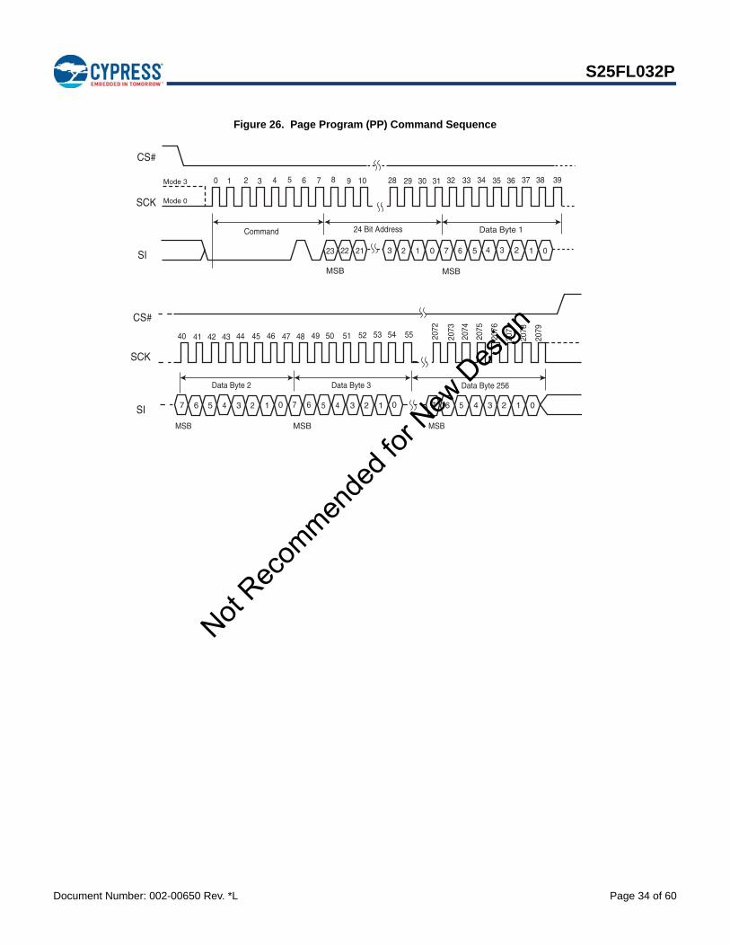
Document Number: 002-00650 Rev. *L Page 34 of 60
S25FL032P
Figure 26. Page Program (PP) Command Sequence
0 3433323130292810987654321 35 36 37 38 39
46454443424140 47 48 49 50 51 52 53 54 55 2073
2072
2076
2075
2074
2079
2078
2077
23 22 21 3 2 1 0 7 6 5 4 3 2 1 0
Data Byte 124 Bit AddressCommand
Data Byte 2 Data Byte 3 Data Byte 256
MSBMSB
MSB MSB MSB
SCK
SI
SCK
SI 7 6 5 4 3 2 1 0 7 6 5 4 3 2 1 0 7 6 5 4 3 2 1 0
CS#
CS#
Mode 0
Mode 3
Not Rec
ommen
ded f
or New
Des
ign

Document Number: 002-00650 Rev. *L Page 35 of 60
S25FL032P
9.15 QUAD Page Program (QPP)The Quad Page Program instruction is similar to the Page Program instruction, except that the Quad Page Program (QPP) instruction allows up to 256 bytes of data to be programmed at previously erased (FFh) memory locations using four pins: IO0 (SI), IO1 (SO), IO2 (W#/ACC), and IO3 (HOLD#), instead of just one pin (SI) as in the case of the Page Program (PP) instruction. This effectively increases the data transfer rate by up to four times, as compared to the Page Program (PP) instruction. The QPP feature can improve performance for PROM Programmer and applications that have slow clock speeds < 5 MHz. Systems with faster clock speed will not realize much benefit for the QPP instruction since the inherent page program time is much greater than the time it take to clock-in the data.
To use QPP, the Quad Enable Bit in the Configuration Register must be set (QUAD = 1). A Write Enable instruction must be executed before the device will accept the Quad Page Program instruction (Status Register-1, WEL = 1). The instruction is initiated by driving the CS# pin low then shifting the instruction code “32h” followed by a 24 bit address (A23-A0) and at least one data byte, into the IO pins. The CS# pin must be held low for the entire length of the instruction while data is being sent to the device. All other functions of Quad Input Page Program are identical to standard Page Program. The QPP instruction sequence is shown below.
Figure 27. QUAD Page Program Instruction Sequence
*MSB
CS#
SCK
SO/IO1
Instruction 24 Bit Address
Byte 2
39
23
*5
SI/IO0
0 1 4 5 6 7 8 9
Byte 1
6
7
*
4
W#/ACC/IO2
HOLD#/IO3
22 21
7
*
3 7
*
3
6 2 6 2
5 1 5 1
4 0 4 0
10
CS#
SCK
SO/IO1
SI/IO0
W#/ACC/IO2
HOLD#/IO3
2 3 28 29 32 33 34 35 36 37 3830 31
Byte 4Byte 3
3 2 1 0
5
6
7
*
4
3
2
1
0
3
2
1
0
5140 41 44 45 46 47 48 49 5042 43 54 5552 53 536
537
538
539
540
541
542
543
Byte 6Byte 5 Byte 8Byte 7 Byte 10Byte 9 Byte 12Byte 11 Byte 254Byte 253 Byte 256Byte 255
7
*
3
6 2
5 1
4 0
7
*
3
6 2
5 1
4 0
7
*
3
6 2
5 1
4 0
7
*
3
6 2
5 1
4 0
7
*
3
6 2
5 1
4 0
7
*
3
6 2
5 1
4 0
7
*
3
6 2
5 1
4 0
7
*
3
6 2
5 1
4 0
7
*
3
6 2
5 1
4 0
7
*
3
6 2
5 1
4 0
7
*
3
6 2
5 1
4 0
7
*
3
6 2
5 1
4 0
Not Rec
ommen
ded f
or New
Des
ign

Document Number: 002-00650 Rev. *L Page 36 of 60
S25FL032P
9.16 Parameter Sector Erase (P4E, P8E)The Parameter Sector Erase (P4E, P8E) command sets all bits at all addresses within a specified sector to a logic 1 (FFh). A WREN command is required prior to writing the Parameter Sector Erase commands.
The host system must drive CS# low, and then write the P4E or P8E command, plus three address bytes on SI. Any address within the sector (see Table 8 on page 16 and Table 9 on page 17) is a valid address for the P4E or P8E command. CS# must be driven low for the entire duration of the P4E/P8E sequence. The command sequence is shown in Figure 28 and Table 10 on page 18.
The host system must drive CS# high after the device has latched the 24th bit of the P4E/P8E address, otherwise the device does not execute the command. The parameter sector erase operation begins as soon as CS# is driven high. The device internally controls the timing of the operation, which requires a period of tSE. The Status Register may be read to check the value of the Write In Progress (WIP) bit while the parameter sector erase operation is in progress. The WIP bit is 1 during the P4E/P8E operation, and is 0 when the operation is completed. The device internally resets the Write Enable Latch to 0 before the operation completes (the exact timing is not specified).
A Parameter Sector Erase (P4E, P8E) instruction applied to a sector that has been Write Protected through the Block Protect Bits will not be executed.
The Parameter Sector Erase Command (P8E) erases two of the 4 KB Sectors in selected address space. The Parameter Sector Erase Command (P8E) erases two sequential 4 KB Parameter Sectors in the selected address space. The address LSB is disregarded so that two sequential 4 KB Parameter Sectors are erased. The 24 Bit Address is any location within the first Sector to be erased (n), and the next sequential 4 KB Parameter Sector will also be erased (n+1). The 4 KB parameter Sector will only be erased properly if n or n+1 is a valid 4 KB parameter Sector; that is, if n is not a valid 4K parameter Sector, then it will not be erased. If n+1 is not a valid 4 KB parameter Sector, then it will not be erased.
Figure 28. Parameter Sector Erase (P4E, P8E) Instruction Sequence
1 3 012 9876540 31302928
Instruction 24 Bit Address
23 2122 13 2 0
SCK
SI
MSB
CS#
20h or 40h
Not Rec
ommen
ded f
or New
Des
ign

Document Number: 002-00650 Rev. *L Page 37 of 60
S25FL032P
9.17 Sector Erase (SE)The Sector Erase (SE) command sets all bits at all addresses within a specified sector to a logic 1. A WREN command is required prior to writing the SE command.
The host system must drive CS# low, and then write the SE command plus three address bytes on SI. Any address within the sector (see Table 6 on page 14) is a valid address for the SE command. CS# must be driven low for the entire duration of the SE sequence. The command sequence is shown in Figure 29 and Table 10 on page 18.
The host system must drive CS# high after the device has latched the 24th bit of the SE address, otherwise the device does not execute the command. The SE operation begins as soon as CS# is driven high. The device internally controls the timing of the operation, which requires a period of tSE. The Status Register may be read to check the value of the Write In Progress (WIP) bit while the SE operation is in progress. The WIP bit is 1 during the SE operation, and is 0 when the operation is completed. The device internally resets the Write Enable Latch to 0 before the operation completes (the exact timing is not specified).
The device only executes a SE command if all Block Protect bits (BP2:BP0) are 0 (see Table 6 on page 14). Otherwise, the device ignores the command.
Figure 29. Sector Erase (SE) Command Sequence
9.18 Bulk Erase (BE)The Bulk Erase (BE) command sets all the bits within the entire memory array to logic 1s. A WREN command is required prior to writing the BE command.
The host system must drive CS# low, and then write the BE command on SI. CS# must be driven low for the entire duration of the BE sequence. The command sequence is shown in Figure 30 and Table 10 on page 18.
The host system must drive CS# high after the device has latched the 8th bit of the CE command, otherwise the device does not execute the command. The BE operation begins as soon as CS# is driven high. The device internally controls the timing of the operation, which requires a period of tBE. The Status Register may be read to check the value of the Write In Progress (WIP) bit while the BE operation is in progress. The WIP bit is 1 during the BE operation, and is 0 when the operation is completed. The device internally resets the Write Enable Latch to 0 before the operation completes (the exact timing is not specified).
The device only executes a BE command if all Block Protect bits (BP2:BP0) are 0 (see Table 6 on page 14). Otherwise, the device ignores the command.
Figure 30. Bulk Erase (BE) Command Sequence
CS#
SCK
SI
SO
MSB
Command 24 bit Address
0 1 2 3 4 5 6 7 8 9 10 28 29 30 31
23 22 21 3 2 1 0
Hi-Z
Mode 0
Mode 3
0 1 2 4 5 6 7
Command
CS#
SCK
SI
3
SO Hi-Z
Mode 0
Mode 3
Not Rec
ommen
ded f
or New
Des
ign

Document Number: 002-00650 Rev. *L Page 38 of 60
S25FL032P
9.19 Deep Power-Down (DP)The Deep Power-Down (DP) command provides the lowest power consumption mode of the device. It is intended for periods when the device is not in active use, and ignores all commands except for the Release from Deep Power-Down (RES) command. The DP mode therefore provides the maximum data protection against unintended write operations. The standard standby mode, which the device goes into automatically when CS# is high (and all operations in progress are complete), should generally be used for the lowest power consumption when the quickest return to device activity is required.
The host system must drive CS# low, and then write the DP command on SI. CS# must be driven low for the entire duration of the DP sequence. The command sequence is shown in Figure 31 and Table 10 on page 18.
The host system must drive CS# high after the device has latched the 8th bit of the DP command, otherwise the device does not execute the command. After a delay of tDP, the device enters the DP mode and current reduces from ISB to IDP (see Table 23 on page 47).
Once the device has entered the DP mode, all commands are ignored except the RES command (which releases the device from the DP mode). The RES command also provides the Electronic Signature of the device to be output on SO, if desired (see Section 9.20 and Section 9.21).
DP mode automatically terminates when power is removed, and the device always powers up in the standard standby mode. The device rejects any DP command issued while it is executing a program, erase, or Write Registers operation, and continues the operation uninterrupted.
Figure 31. Deep Power-Down (DP) Command Sequence
CS#
SCK
SI
SO
Standby Mode Deep Power-down Mode
Command
0 1 2 3 4 5 6 7
tDP
Hi-Z
Mode 0
Mode 3
Not Rec
ommen
ded f
or New
Des
ign

Document Number: 002-00650 Rev. *L Page 39 of 60
S25FL032P
9.20 Release from Deep Power-Down (RES)The device requires the Release from Deep Power-Down (RES) command to exit the Deep Power-Down mode. When the device is in the Deep Power-Down mode, all commands except RES are ignored.
The host system must drive CS# low and write the RES command to SI. CS# must be driven low for the entire duration of the sequence. The command sequence is shown in Figure 32 and Table 10 on page 18.
The host system must drive CS# high tRES(max) after the 8-bit RES command byte. The device transitions from DP mode to the standby mode after a delay of tRES (see Figure 25). In the standby mode, the device can execute any read or write command.
Note: The RES command does not reset the Write Enable Latch (WEL) bit.
Figure 32. Release from Deep Power-Down (RES) Command Sequence
9.20.1 Release from Deep Power-Down and Read Electronic Signature (RES)The device features an 8-bit Electronic Signature, which can be read using the RES command. See Figure 33 and Table 10 on page 18 for the command sequence and signature value. The Electronic Signature is not to be confused with the identification data obtained using the RDID command. The device offers the Electronic Signature so that it can be used with previous devices that offered it; however, the Electronic Signature should not be used for new designs, which should read the RDID data instead.
After the host system drives CS# low, it must write the RES command followed by 3 dummy bytes to SI (each bit is latched on SI during the rising edge of SCK). The Electronic Signature is then output on SO; each bit is shifted out on the falling edge of SCK. The RES operation is terminated by driving CS# high after the Electronic Signature is read at least once. Additional clock cycles on SCK with CS# low cause the device to output the Electronic Signature repeatedly.
When CS# is driven high, the device transitions from DP mode to the standby mode after a delay of tRES, as previously described. The RES command always provides access to the Electronic Signature of the device and can be applied even if DP mode has not been entered. Any RES command issued while an erase, program, or Write Registers operation is in progress not executed, and the operation continues uninterrupted.
Figure 33. Release from Deep Power-Down and RES Command Sequence
CS#
SCK
SI
SO
0 1 2 3 4 5 6 7
Command
Deep Power-down Mode
tRES
Standby Mode
Mode 0
Hi-Z
Mode 3
CS#
SCK
SI
SO
3 Dummy Bytes
Hi-Z
MSB
Deep Power-Down Mode Standby Mode
0 1 2 3 4 5 6 7 8 9 10 28 29 30 31 32 33 34 35 36 37 38
Electronic ID
CommandtRES
23 22 21 3 2 1 0
7 6 5 4 3 2 1 0
MSB
39
Not Rec
ommen
ded f
or New
Des
ign

Document Number: 002-00650 Rev. *L Page 40 of 60
S25FL032P
9.21 Clear Status Register (CLSR)The Clear Status Register command resets bit SR5 (Erase Fail Flag) and bit SR6 (Program Fail Flag). It is not necessary to set the WEL bit before the Clear SR Fail Flags command is executed. The WEL bit will be unchanged after this command is executed. This command also resets the State machine and loads latches
Figure 34. Clear Status Register (CLSR) Instruction Sequence
9.22 OTP Program (OTPP)The OTP Program command programs data in the OTP region, which is in a different address space from the main array data. Refer to, Section 10., OTP Regions on page 41 for details on the OTP region. The protocol of the OTP Program command is the same as the Page Program command, except that the OTP Program command requires exactly one byte of data; otherwise, the command will be ignored. To program the OTP in bit granularity, the rest of the bits within the data byte can be set to “1”.
The OTP memory space can be programmed one or more times, provided that the OTP memory space is not locked (as described in “Locking OTP Regions”). Subsequent OTP programming can be performed only on the unprogrammed bits (that is, “1” data).
Note: The Write Enable (WREN) command must precede the OTPP command before programming of the OTP can occur.
Figure 35. OTP Program Instruction Sequence
9.23 Read OTP Data Bytes (OTPR)The Read OTP Data Bytes command reads data from the OTP region. Refer to Section 10. for details on the OTP region. The protocol of the Read OTP Data Bytes command is the same as the Fast Read Data Bytes command except that it will not wrap to the starting address after the OTP address is at its maximum; instead, the data will be indeterminate.
Figure 36. Read OTP Instruction Sequence
32 76540
Instruction
SCK
SI
1
CSS#
1 32 109876540 31302928
Instruction 24 BitAddress
23 2122 13 2 0
3635343332 393837
13 2 07 6 5 4
Data Byte 1
SCK
SI
MSB MSB
CS#
1 3 012 987654 130 302928
Instruction 24 BitAddress
23 2122 13 2 0
13 2 07 6 5 4
36353433 9323 3837
13 2 07 6 5 4
Dummy Byte
44434241 7404 4645
DATA OUT 1 DATA OUT 2
SCK
SI
SO
MSB
High Impedance 7
MSB
CS
Not Rec
ommen
ded f
or New
Des
ign

Document Number: 002-00650 Rev. *L Page 41 of 60
S25FL032P
10. OTP RegionsThe OTP Regions are separately addressable from the main array and consists of two 8-byte (ESN), thirty 16-byte, and one 10-byte regions that can be individually locked.
The two 8-byte ESN region is a special order part (please contact your local Cypress sales representative for further details). The two 8-byte regions enable permanent part identification through an Electronic Serial Number (ESN). The customer can utilize the ESN to pair a Flash device with the system CPU/ASIC to prevent system cloning. The Cypress factory programs and locks the lower 8-byte ESN with a 64-bit randomly generated, unique number. The upper 8-byte ESN is left blank for customer use or, if special ordered, Cypress can program (and lock) in a unique customer ID.
The thirty 16-byte and one 10-byte OTP regions are open for the customer usage.
The thirty 16-byte, one 10-byte, and upper 8-byte ESN OTP regions can be individually locked by the end user. Once locked, the data cannot changed. The locking process is permanent and cannot be undone.
The following general conditions should be noted with respect to the OTP Regions:
On power-up, or following a hardware reset, or at the end of an OTPP or an OTPR command, the device reverts to sending commands to the normal address space.
Reads or Programs outside of the OTP Regions will be ignored
The OTP Region is not accessible when the device is executing an Embedded Program or Embedded Erase algorithm.
The ACC function is not available when accessing the OTP Regions.
The thirty 16-byte and one 10-byte OTP regions are left open for customer usage, but special care of the OTP locking must be maintained, or else a malevolent user can permanently lock the OTP regions. This is not a concern, if the OTP regions are not used.
10.1 Programming OTP Address SpaceThe protocol of the OTP Program command (42h) is the same as the Page Program command. Refer to Table 10 for the command description and protocol. The OTP Program command can be issued multiple times to any given OTP address, but this address space can never be erased. After a given OTP region is programmed, it can be locked to prevent further programming with the OTP lock registers (refer to Section 10.3). The valid address range for OTP Program is depicted in the figure below. OTP Program operations outside the valid OTP address range will be ignored.
10.2 Reading OTP DataThe protocol of the OTP Read command (4Bh) is the same as that of the Fast Read command. Refer to Table 10 for the command description and protocol. The valid address range for OTP Reads is depicted in the figure below. OTP Read operations outside the valid OTP address range will yield indeterminate data.
Table 19. ESN1 and ESN2
Lock register ESN1 (Bit 0) Lock register ESN2 (Bit 1) ESN1 region contains ESN2 region contains
Standard part 1h 1h 0h 0h
Special order part 1h 1h/0h Unique random pattern Factory/Customer programmed pattern
Not Rec
ommen
ded f
or New
Des
ign

Document Number: 002-00650 Rev. *L Page 42 of 60
S25FL032P
10.3 Locking OTP RegionsIn order to permanently lock the ESN and OTP regions, individual bits at the specified addresses can be set to lock specific regions of OTP memory, as highlighted in Figure 37 and Figure 38.
Figure 37. OTP Memory Map - Part 1
Notes1. Bit 0 at address 0x100h locks ESN1 region.
2. Bit 1 at address 0x100h locks ESN2 region.
3. Bits 2-7 (“X”) are NOT programmable and will be ignored.
ADDRESS OTP REGION
0x213h
0x204h 0x203h
0x1F4h 0x1F3h
0x1E4h 0x1E3
0x1D4h 0x1D3h
0x1C4h 0x1C3h
0x1B4h 0x1B3h
0x1A4h 0x1A3h
0x194h 0x193h
0x184h 0x183h
0x174h 0x173h
0x164h 0x163h
0x154h 0x153h
0x144h Address Bit Locks Region… 0x143h 0 OTP1
1 OTP2 0x134h 2 OTP3 0x133h 3 OTP4
4 OTP5 0x124h 5 OTP6 0x123h 6 OTP7
7 OTP8 0x114h 0 OTP9 0x113h 1 OTP10 0x112h 2 OTP11 0x111h 3 OTP12
4 OTP13 0x10Ah 5 OTP14 0x109h 6 OTP15
7 OTP16 0x102h 0 ESN1 0x101h Reserved 1 ESN2 0x100h 2 - 7 Reserved
16 bytes (OTP15)
16 bytes (OTP14)
16 bytes (OTP13)
16 bytes (OTP12)
16 bytes (OTP5)
16 bytes (OTP11)
16 bytes (OTP10)
16 bytes (OTP9)
16 bytes (OTP6)
16 bytes (OTP7)
16 bytes (OTP8)
0x100h
0x112h
0x113h
16 bytes (OTP16)
8 bytes (ESN1)
8 bytes (ESN2)
16 bytes (OTP1)
16 bytes (OTP2)
16 bytes (OTP3)
16 bytes (OTP4)
X X X X X X Bit 1 Bit 0
Bit 7 Bit 6 Bit 5 Bit 4 Bit 3 Bit 2 Bit 1 Bit 0Bit 7 Bit 6 Bit 5 Bit 4 Bit 3 Bit 2 Bit 1 Bit 0
Not Rec
ommen
ded f
or New
Des
ign

Document Number: 002-00650 Rev. *L Page 43 of 60
S25FL032P
Figure 38. OTP Memory Map - Part 2
Note1. Bit 7 (“X”) at address 0x215h is NOT programmable and will be ignored.
ADDRESS OTP REGION
0x2FFh
0x2F6h 0x2F5h
0x2E6h 0x2E5
0x2D6h 0x2D5h
0x2C6h 0x2C5h
0x2B6h 0x2B5h
0x2A6h 0x2A5h
0x296h 0x295h
0x286h 0x285h
0x276h 0x275h
0x266h 0x265h Address Bit Locks Region…
0 OTP17 0x256h 1 OTP18 0x255h 2 OTP19
3 OTP20 0x246h 4 OTP21 0x245h 5 OTP22
6 OTP23 0x236h 7 OTP24 0x235h 0 OTP25
1 OTP26 0x226h 2 OTP27 0x225h 3 OTP28
4 OTP29 0x216h 5 OTP30 0x215h 6 OTP31 0x214h 7 Reserved
16 bytes (OTP21) 0x214h
0x215h
16 bytes (OTP17)
16 bytes (OTP18)
16 bytes (OTP19)
16 bytes (OTP20)
16 bytes (OTP27)
16 bytes (OTP26)
16 bytes (OTP25)
16 bytes (OTP22)
16 bytes (OTP23)
16 bytes (OTP24)
10 bytes (OTP31)
16 bytes (OTP30)
16 bytes (OTP29)
16 bytes (OTP28)
Bit 7 Bit 6 Bit 5 Bit 4 Bit 3 Bit 2 Bit 1 Bit 0X Bit 6 Bit 5 Bit 4 Bit 3 Bit 2 Bit 1 Bit 0Not
Recom
mende
d for
New D
esign

Document Number: 002-00650 Rev. *L Page 44 of 60
S25FL032P
11. Power-up and Power-downDuring power-up and power-down, certain conditions must be observed. CS# must follow the voltage applied on VCC, and must not be driven low to select the device until VCC reaches the allowable values as follows (see Figure 39 and Table 20 on page 45):
At power-up, VCC (min.) plus a period of tPU
At power-down, GND
A pull-up resistor on Chip Select (CS#) typically meets proper power-up and power-down requirements.
No Read, Write Registers, program, or erase command should be sent to the device until VCC rises to the VCC min., plus a delay of tPU. At power-up, the device is in standby mode (not Deep Power-Down mode) and the WEL bit is reset (0).
Each device in the host system should have the VCC rail decoupled by a suitable capacitor close to the package pins (this capacitor is generally of the order of 0.1 µF), as a precaution to stabilizing the VCC feed.
When VCC drops from the operating voltage to below the minimum VCC threshold at power-down, all operations are disabled and the device does not respond to any commands. Note that data corruption may result if a power-down occurs while a Write Registers, program, or erase operation is in progress.
Figure 39. Power-Up Timing Diagram
Figure 40. Power-Down and Voltage Drop
Vcc
Vcc(max)
Vcc(min)
Full Device AccesstPU
Time
Vcc
VCC (max)
VCC (min)
VCC (cut-off)
VCC (low)
tPD
tPUDevice AccessAllowed
No Device Access Allowed
Time
Not Rec
ommen
ded f
or New
Des
ign

Document Number: 002-00650 Rev. *L Page 45 of 60
S25FL032P
12. Initial Delivery StateThe device is delivered with the memory array erased, that is, all bits are set to 1 (FFh) upon initial factory shipment. The Status Register and Configuration Register contains 00h (all bits are set to 0).
13. Program Acceleration via W#/ACC PinThe program acceleration function requires applying VHH to the W#/ACC input, and then waiting a period of tWC. Minimum tVHH rise and fall times is required for W#/ACC to change to VHH from VIL or VIH. Removing VHH from the W#/ACC pin returns the device to normal operation after a period of tWC.
Figure 41. ACC Program Acceleration Timing Requirements
NoteOnly Read Status Register (RDSR) and Page Program (PP) operation are allow when ACC is at (VHH). The W#/ACC pin is disabled during Quad I/O mode.
Table 20. Power-Up / Power-Down Voltage and Timing
Symbol Parameter Min Max Unit
VCC(min) VCC (minimum operation voltage) 2.7 V
VCC(cut-off) VCC (Cut off where re-initialization is needed) 2.4 V
VCC(low) VCC (Low voltage for initialization to occur at read/standby)VCC (Low voltage for initialization to occur at embedded)
0.22.3
V
tPU VCC(min.) to device operation 300 µs
tPD VCC (low duration time) 1.0 µs
ACC
Command OK
VHH
VIL or VIH
tVHH
tWC tWC
tVHH
VIL or VIH
Table 21. ACC Program Acceleration Specifications
Symbol Parameter Min. Max Unit
VHH ACC Pin Voltage High 8.5 9.5 V
tVHH ACC Voltage Rise and Fall time 2.2 µs
tWC ACC at VHH and VIL or VIH to First command 5 µs
Not Rec
ommen
ded f
or New
Des
ign

Document Number: 002-00650 Rev. *L Page 46 of 60
S25FL032P
14. Electrical Specifications
14.1 Absolute Maximum Ratings
Notes1. Minimum DC voltage on input or I/Os is -0.5 V. During voltage transitions, inputs or I/Os may undershoot GND to -2.0 V for periods of up to 20 ns. See Figure 42.
Maximum DC voltage on input or I/Os is VCC + 0.5 V. During voltage transitions inputs or I/Os may overshoot to VCC + 2.0 V for periods up to 20 ns. See Figure 43.
2. No more than one output may be shorted to ground at a time. Duration of the short circuit should not be greater than one second.
3. Stresses above those listed under “Absolute Maximum Ratings” may cause permanent damage to the device. This is a stress rating only; functional operation of the device at these or any other conditions above those indicated in the operational sections of this data sheet is not implied. Exposure of the device to absolute maximum rating conditions for extended periods may affect device reliability.
Figure 42. Maximum Negative Overshoot Waveform
Figure 43. Maximum Positive Overshoot Waveform
Description Rating
Ambient Storage Temperature 65 °C to +150 °C
Voltage with Respect to Ground: All Inputs and I/Os 0.5 V to VCC+0.5 V
Output Short Circuit Current (Note 2) 200 mA
20 ns
20 ns
+0.8V
–0.5V
20 ns
–2.0V
20 ns
20 ns
VCC +2.0V
VCC+0.5V
20 ns
2.0V
Not Rec
ommen
ded f
or New
Des
ign

Document Number: 002-00650 Rev. *L Page 47 of 60
S25FL032P
15. Operating Ranges
NoteOperating ranges define those limits between which functionality of the device is guaranteed.
16. DC CharacteristicsThis section summarizes the DC Characteristics of the device. Designers should check that the operating conditions in their circuit match the measurement conditions specified in the Test Specifications in Table 24 on page 48, when relying on the quoted parameters.
Table 22. Operating Ranges
Description Rating
Ambient Operating Temperature (TA)Industrial –40 °C to +85 °C
Automotive In-Cabin –40 °C to +105 °C
Positive Power Supply Voltage Range 2.7 V to 3.6 V
Table 23. DC Characteristics (CMOS Compatible)
Symbol Parameter Test ConditionsLimits
UnitMin. Typ* Max
VCC Supply voltage 2.7 3.6 V
VHHACC Program Acceleration Voltage
VCC = 2.7 V to 3.6 V 8.5 9.5 V
VIL Input Low Voltage** –0.3 0.3 x VCC V
VIH Input High Voltage** 0.7 x VCC VCC +0.5 V
VOL Output Low Voltage IOL = 1.6 mA, VCC = VCC min. 0.4 V
VOH Output High Voltage IOH = -0.1 mA VCC-0.6 V
ILI Input Leakage CurrentVCC = VCC Max,
VIN = VCC or GND2 µA
ILO Output Leakage CurrentVCC = VCC Max,
VIN = VCC or GND2 µA
ICC1Active Power Supply Current - READ (SO = Open)
At 80 MHz (Dual or Quad)
38
mAAt 104 MHz (Serial) 25
At 40 MHz (Serial) 12
ICC2Active Power Supply Current (Page Program)
CS# = VCC 26 mA
ICC3Active Power Supply Current (WRR)
CS# = VCC 15 mA
ICC4 Active Power Supply Current (SE) CS# = VCC 26 mA
ICC5 Active Power Supply Current (BE) CS# = VCC 26 mA
ISB1 Standby Current CS# = VCC;
SO + VIN = GND or VCC80 200 µA
IPD Deep Power-down CurrentCS# = VCC;
SO + VIN = GND or VCC3 10 µA
*Typical values are at TAI = 25 °C and VCC = 3 V
Not Rec
ommen
ded f
or New
Des
ign

Document Number: 002-00650 Rev. *L Page 48 of 60
S25FL032P
17. Test ConditionsFigure 44. AC Measurements I/O Waveform
0.8 VCC
0.2 VCC
0.7 VCC
0.3 VCC
Input Levels
Input and Output Timing Reference levels
0.5 VCC
Table 24. Test Specifications
Symbol Parameter Min Max Unit
CL Load Capacitance 30 pF
Input Rise and Fall Times 5 ns
Input Pulse Voltage 0.2 VCC to 0.8 VCC V
Input Timing Reference Voltage 0.3 VCC to 0.7 VCC V
Output Timing Reference Voltage 0.5 VCC V
Not Rec
ommen
ded f
or New
Des
ign

Document Number: 002-00650 Rev. *L Page 49 of 60
S25FL032P
18. AC Characteristics
Table 25. AC Characteristics
Symbol (Notes) Parameter (Notes)Min.
(Notes) Typ (Notes) Max (Notes) Unit
fRSCK Clock Frequency for READ command DC 40 MHz
SCK Clock Frequency for RDID command DC 50
fCSCK Clock Frequency for all others:FAST_READ, PP, QPP, P4E, P8E, SE, BE, DP,RES, WREN, WRDI, RDSR, WRR, READ_ID
DC 104 (serial)80 (dual/quad)
MHz
tWH, tCH Clock High Time (5) 4.5 ns
tWL, tCL Clock Low Time (5) 4.5 ns
tCRT, tCLCH Clock Rise Time (slew rate) 0.1 V/ns
tCFT, tCHCL Clock Fall Time (slew rate) 0.1 V/ns
tCSCS# High Time (Read Instructions)CS# High Time (Program/Erase)
10
50ns
tCSSCS# Active Setup Time(relative to SCK) 3 ns
tCSHCS# Active Hold Time(relative to SCK) 3 ns
tSU:DAT Data in Setup Time 3 ns
tHD:DAT Data in Hold Time 2 ns
tV Clock Low to Output Valid 0
8 (Serial)
9.5 (Dual/Quad)
6.5 (Serial)
8 (Dual/Quad)
7 (Dual/Quad)
ns
tHO Output Hold Time 2 ns
tDIS Output Disable Time 8 ns
tHLCHHOLD# Active Setup Time(relative to SCK) 3 ns
tCHHHHOLD# Active Hold Time(relative to SCK) 3 ns
tHHCHHOLD# Non Active Setup Time(relative to SCK) 3 ns
tCHHLHOLD# Non Active Hold Time(relative to SCK) 3 ns
tHZ HOLD# enable to Output Invalid 8 ns
tLZ HOLD# disable to Output Valid 8 ns
tWPS W#/ACC Setup Time (4) 20 ns
tWPH W#/ACC Hold Time (4) 100 ns
tW WRR Cycle Time 50 ms
tPP Page Programming (1)(2) 1.5 3 ms
tEP Page Programming (ACC = 9 V) (1)(2)(3) 1.2 2.4 ms
Not Rec
ommen
ded f
or New
Des
ign

Document Number: 002-00650 Rev. *L Page 50 of 60
S25FL032P
Notes1. Typical program and erase times assume the following conditions: 25°C, VCC = 3.0 V; 10,000 cycles; checkerboard data pattern.
2. Under worst-case conditions of 85°C; VCC = 2.7 V; 100,000 cycles.
3. Acceleration mode (9 V ACC) only in Program mode, not Erase.
4. Only applicable as a constraint for WRR instruction when SRWD is set to a ‘1’.
5. tWH + tWL must be less than or equal to 1/fC.
6. Full Vcc range (2.7 – 3.6 V) & CL = 30 pF.
7. Regulated Vcc range (3.0 – 3.6 V) & CL = 30 pF.
8. Regulated Vcc range (3.0 – 3.6 V) & CL = 15 pF.
18.1 Capacitance
Notes1. Sampled, not 100% tested.
2. Test conditions TA = 25°C, f = 1.0 MHz.
3. For more information on pin capacitance, please consult the IBIS models.
Figure 45. SPI Mode 0 (0,0) Input Timing
tSE Sector Erase Time (64 KB) (1)(2) 0.5 2 sec
tPEParameter Sector Erase Time (1)(2)(4 KB or 8 KB) 200 800 ms
tBE Bulk Erase Time (1)(2) 32 64 sec
tRES Deep Power-down to Standby Mode 30 µs
tDP Time to enter Deep Power-down Mode 10 µs
tVHH ACC Voltage Rise and Fall time 2.2 µs
tWC ACC at VHH and VIL or VIH to first command 5 µs
Table 25. AC Characteristics (Continued)
Symbol (Notes) Parameter (Notes) Min. (Notes)
Typ (Notes) Max (Notes) Unit
Symbol Parameter Test Conditions Min Typ Max Unit
CINInput Capacitance(applies to SCK, PO7-PO0, SI, CS#) VOUT = 0 V 9.0 12.0 pF
COUTOutput Capacitance(applies to PO7-PO0, SO) VIN = 0 V 12.0 16.0 pF
CS#
SCK
SI
SO
tCSH tCSS tCSH tCSS
tCFTtCRT
MSB IN LSB IN
Hi-Z
tSU:DAT tHD:DAT
tCSNot
Recom
mende
d for
New D
esign

Document Number: 002-00650 Rev. *L Page 51 of 60
S25FL032P
Figure 46. SPI Mode 0 (0,0) Output Timing
Figure 47. HOLD# Timing
Figure 48. Write Protect Setup and Hold Timing during WRR when SRWD = 1
CS#
SCK
SO LSB OUT
tWH
tWL tDIStV
tHO
tVtHO
tCHHL
tHZ
tCHHH
tHLCHtHHCH
tLZ
CS#
SCK
SO
SI
HOLD#
W#
CS#
SCK
SI
SO Hi-Z
tWPS tWPH
Not Rec
ommen
ded f
or New
Des
ign

Document Number: 002-00650 Rev. *L Page 52 of 60
S25FL032P
19. Physical Dimensions
19.1 SOC008 wide — 8-pin Plastic Small Outline Package (208-mils Body Width)
5.28 BSCD
0.51
20
10
0
N
L1
L2
E1
L
e
E
15°
0°
5°
8°
0.76
5.28 BSC
8.00 BSC
1.36 REF
0.25 BSC
8
1.27 BSC
1.70
1.75
0.05
0.33
0.36
0.15
0.19
c1
c
b1
b
A2
A1
A
1.90
2.16
0.25
0.48
0.46
0.20
0.24
0-8° REF
2. DIMENSIONING AND TOLERANCING PER ASME Y14.5M - 1994.3. DIMENSION D DOES NOT INCLUDE MOLD FLASH, PROTRUSIONS OR GATE BURRS.
END. DIMENSION E1 DOES NOT INCLUDE INTERLEAD FLASH OR PROTRUSION.INTERLEAD FLASH OR PROTRUSION SHALL NOT EXCEED 0.25 mm PER SIDE.
1. ALL DIMENSIONS ARE IN MILLIMETERS.
NOTES:
D AND E1 DIMENSIONS ARE DETERMINED AT DATUM H.
FLASH, BUT INCLUSIVE OF ANY MISMATCH BETWEEN THE TOP AND BOTTOM OFEXCLUSIVE OF MOLD FLASH, TIE BAR BURRS, GATE BURRS AND INTERLEAD
4. THE PACKAGE TOP MAY BE SMALLER THAN THE PACKAGE BOTTOM. DIMENSIONS
5. DATUMS A AND B TO BE DETERMINED AT DATUM H.6. "N" IS THE MAXIMUM NUMBER OF TERMINAL POSITIONS FOR THE SPECIFIED
7. THE DIMENSIONS APPLY TO THE FLAT SECTION OF THE LEAD BETWEEN 0.10 TO
MAXIMUM MATERIAL CONDITION. THE DAMBAR CANNOT BE LOCATED ON THE
8. DIMENSION "b" DOES NOT INCLUDE DAMBAR PROTRUSION. ALLOWABLE DAMBAR
LOWER RADIUS OF THE LEAD FOOT.
IDENTIFIER MUST BE LOCATED WITHIN THE INDEX AREA INDICATED.9. THIS CHAMFER FEATURE IS OPTIONAL. IF IT IS NOT PRESENT, THEN A PIN 1
10. LEAD COPLANARITY SHALL BE WITHIN 0.10 mm AS MEASURED FROM THE
MOLD FLASH, PROTRUSIONS OR GATE BURRS SHALL NOT EXCEED 0.15 mm PER
D AND E1 ARE DETERMINED AT THE OUTMOST EXTREMES OF THE PLASTIC BODY
0.25 mm FROM THE LEAD TIP.
PROTRUSION SHALL BE 0.10 mm TOTAL IN EXCESS OF THE "b" DIMENSION AT
THE PLASTIC BODY.
PACKAGE LENGTH.
SEATING PLANE.
DIMENSIONSSYMBOL
MIN. NOM. MAX.
-
-
-
-
-
-
-
-
-
-
002-15548 **
Not Rec
ommen
ded f
or New
Des
ign

Document Number: 002-00650 Rev. *L Page 53 of 60
S25FL032P
19.2 SO3 016 — 16-pin Wide Plastic Small Outline Package (300-mils Body Width)
0.33 C
0.25 M DC A-B
0.20 C A-B
0.10 C
0.10 C
0.10 C D2X
2. DIMENSIONING AND TOLERANCING PER ASME Y14.5M - 1994.3. DIMENSION D DOES NOT INCLUDE MOLD FLASH, PROTRUSIONS OR GATE BURRS.
END. DIMENSION E1 DOES NOT INCLUDE INTERLEAD FLASH OR PROTRUSION.INTERLEAD FLASH OR PROTRUSION SHALL NOT EXCEED 0.25 mm PER SIDE.
1. ALL DIMENSIONS ARE IN MILLIMETERS.
NOTES:
D AND E1 DIMENSIONS ARE DETERMINED AT DATUM H.
FLASH, BUT INCLUSIVE OF ANY MISMATCH BETWEEN THE TOP AND BOTTOM OFEXCLUSIVE OF MOLD FLASH, TIE BAR BURRS, GATE BURRS AND INTERLEAD
4. THE PACKAGE TOP MAY BE SMALLER THAN THE PACKAGE BOTTOM. DIMENSIONS
5. DATUMS A AND B TO BE DETERMINED AT DATUM H.6. "N" IS THE MAXIMUM NUMBER OF TERMINAL POSITIONS FOR THE SPECIFIED
7. THE DIMENSIONS APPLY TO THE FLAT SECTION OF THE LEAD BETWEEN 0.10 TO
MAXIMUM MATERIAL CONDITION. THE DAMBAR CANNOT BE LOCATED ON THE
8. DIMENSION "b" DOES NOT INCLUDE DAMBAR PROTRUSION. ALLOWABLE DAMBAR
LOWER RADIUS OF THE LEAD FOOT.
IDENTIFIER MUST BE LOCATED WITHIN THE INDEX AREA INDICATED.9. THIS CHAMFER FEATURE IS OPTIONAL. IF IT IS NOT PRESENT, THEN A PIN 1
10. LEAD COPLANARITY SHALL BE WITHIN 0.10 mm AS MEASURED FROM THE
h
0
D
L2
N
e
A1
b
c
E
E1
A
0.75
10.30 BSC
1.27 BSC
0.30
10.30 BSC
0.33
0°
0.25
16
0.20
7.50 BSC
0.10
0.31
8°
0.51
2.652.35
A2 2.05 2.55
b1 0.27 0.48
0.300.20c1
L10.40L 1.27
1.40 REF
0.25 BSC
0 5° 15°0 0°
1
2 -
DIMENSIONSSYMBOL
MIN. NOM. MAX.
-
-
-
-
-
-
-
-
-
-
-
-
MOLD FLASH, PROTRUSIONS OR GATE BURRS SHALL NOT EXCEED 0.15 mm PER
D AND E1 ARE DETERMINED AT THE OUTMOST EXTREMES OF THE PLASTIC BODY
0.25 mm FROM THE LEAD TIP.
PROTRUSION SHALL BE 0.10 mm TOTAL IN EXCESS OF THE "b" DIMENSION AT
THE PLASTIC BODY.
PACKAGE LENGTH.
SEATING PLANE.
002-15547 *A
Not Rec
ommen
ded f
or New
Des
ign

Document Number: 002-00650 Rev. *L Page 54 of 60
S25FL032P
19.3 UNE008 — USON 8-contact (5 × 6 mm) No-Lead Package
BILATERAL COPLANARITY ZONE APPLIES TO THE EXPOSED HEAT SINKPIN #1 ID ON TOP WILL BE LOCATED WITHIN THE INDICATED ZONE.MAXIMUM ALLOWABLE BURR IS 0.076mm IN ALL DIRECTIONS.
DIMENSION "b" APPLIES TO METALLIZED TERMINAL AND IS MEASURED N IS THE TOTAL NUMBER OF TERMINALS. ALL DIMENSIONS ARE IN MILLIMETERS. DIMENSIONING AND TOLERANCING CONFORMS TO ASME Y14.5M-1994.
NOTES:
MAX. PACKAGE WARPAGE IS 0.05mm.
8
7.6.5
2.
43.
1.
9
THE OPTIONAL RADIUS ON THE OTHER END OF THE TERMINAL, THE DIMENSION "b" SHOULD NOT BE MEASURED IN THAT RADIUS AREA.ND REFERS TO THE NUMBER OF TERMINALS ON D SIDE.
84
1.27 BSC.
0.40
6.00 BSC
5.00 BSC
4.003.40
0.20 MIN.
0.500.02
0.60
A1
K
A
E2DE
D2b
LNDNe
0.00
3.30
0.45
3.900.35
0.55
3.50
0.050.55
4.100.45
0.65
A3 0.20 REF
DIMENSIONSSYMBOL
MIN. NOM. MAX.
BETWEEN 0.15 AND 0.30mm FROM TERMINAL TIP. IF THE TERMINAL HAS
SLUG AS WELL AS THE TERMINALS.
002-18903 **
Not Rec
ommen
ded f
or New
Des
ign
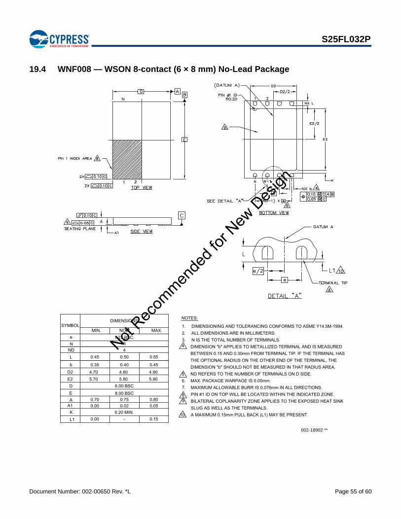
Document Number: 002-00650 Rev. *L Page 55 of 60
S25FL032P
19.4 WNF008 — WSON 8-contact (6 × 8 mm) No-Lead Package
A MAXIMUM 0.15mm PULL BACK (L1) MAY BE PRESENT.
BILATERAL COPLANARITY ZONE APPLIES TO THE EXPOSED HEAT SINKPIN #1 ID ON TOP WILL BE LOCATED WITHIN THE INDICATED ZONE.MAXIMUM ALLOWABLE BURR IS 0.076mm IN ALL DIRECTIONS.
DIMENSION "b" APPLIES TO METALLIZED TERMINAL AND IS MEASURED N IS THE TOTAL NUMBER OF TERMINALS. ALL DIMENSIONS ARE IN MILLIMETERS. DIMENSIONING AND TOLERANCING CONFORMS TO ASME Y14.5M-1994.
NOTES:
MAX. PACKAGE WARPAGE IS 0.05mm.
8
7.6.5
2.
43.
1.
9
10
THE OPTIONAL RADIUS ON THE OTHER END OF THE TERMINAL, THE DIMENSION "b" SHOULD NOT BE MEASURED IN THAT RADIUS AREA.ND REFERS TO THE NUMBER OF TERMINALS ON D SIDE.
84
1.27 BSC.
0.40
8.00 BSC
6.00 BSC
4.805.80
0.750.02
0.50
A1
L1
A
E2DE
D2b
LNDNe
0.00
5.70
0.70
4.700.35
0.45
5.90
0.050.80
4.900.45
0.55
DIMENSIONSSYMBOL
MIN. NOM. MAX.
BETWEEN 0.15 AND 0.30mm FROM TERMINAL TIP. IF THE TERMINAL HAS
SLUG AS WELL AS THE TERMINALS.0.20 MIN.K
-0.00 0.15
002-18902 **
Not Rec
ommen
ded f
or New
Des
ign
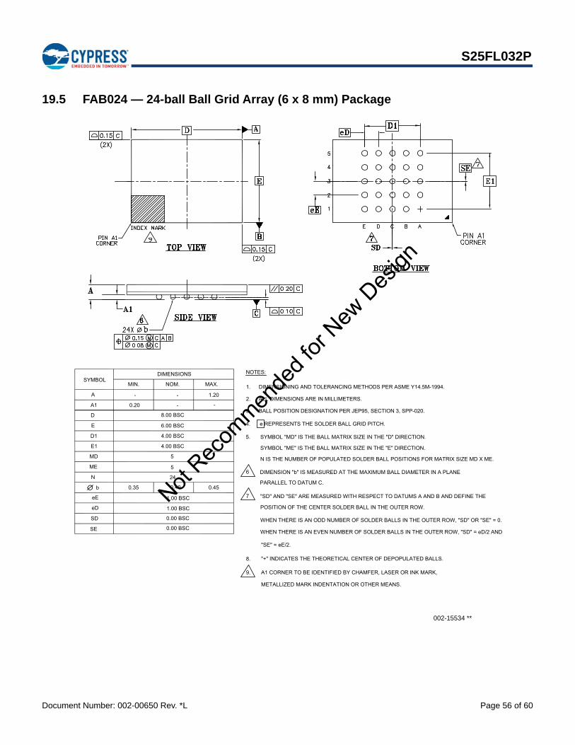
Document Number: 002-00650 Rev. *L Page 56 of 60
S25FL032P
19.5 FAB024 — 24-ball Ball Grid Array (6 x 8 mm) Package
METALLIZED MARK INDENTATION OR OTHER MEANS.
A1 CORNER TO BE IDENTIFIED BY CHAMFER, LASER OR INK MARK,
N IS THE NUMBER OF POPULATED SOLDER BALL POSITIONS FOR MATRIX SIZE MD X ME.
WHEN THERE IS AN EVEN NUMBER OF SOLDER BALLS IN THE OUTER ROW, "SD" = eD/2 AND
WHEN THERE IS AN ODD NUMBER OF SOLDER BALLS IN THE OUTER ROW, "SD" OR "SE" = 0.
POSITION OF THE CENTER SOLDER BALL IN THE OUTER ROW.
"SD" AND "SE" ARE MEASURED WITH RESPECT TO DATUMS A AND B AND DEFINE THE
SYMBOL "ME" IS THE BALL MATRIX SIZE IN THE "E" DIRECTION.
SYMBOL "MD" IS THE BALL MATRIX SIZE IN THE "D" DIRECTION.
e REPRESENTS THE SOLDER BALL GRID PITCH.
DIMENSION "b" IS MEASURED AT THE MAXIMUM BALL DIAMETER IN A PLANE
BALL POSITION DESIGNATION PER JEP95, SECTION 3, SPP-020.
DIMENSIONING AND TOLERANCING METHODS PER ASME Y14.5M-1994.
"+" INDICATES THE THEORETICAL CENTER OF DEPOPULATED BALLS.8.
9.
7
ALL DIMENSIONS ARE IN MILLIMETERS.
PARALLEL TO DATUM C.
5.
6
4.
3.
2.
1.
NOTES:
SD
b
eD
eE
ME
N
0.35
0.00 BSC
1.00 BSC
1.00 BSC
0.40
24
5
0.45
D1
MD
E1
E
D
A
A1 0.20
-
4.00 BSC
4.00 BSC
5
6.00 BSC
8.00 BSC
-
- 1.20
-
SE 0.00 BSC
DIMENSIONSSYMBOL
MIN. NOM. MAX.
"SE" = eE/2.
002-15534 **
Not Rec
ommen
ded f
or New
Des
ign

Document Number: 002-00650 Rev. *L Page 57 of 60
S25FL032P
19.6 FAC024 — 24-ball Ball Grid Array (6 x 8 mm) Package
METALLIZED MARK INDENTATION OR OTHER MEANS.
A1 CORNER TO BE IDENTIFIED BY CHAMFER, LASER OR INK MARK,
N IS THE NUMBER OF POPULATED SOLDER BALL POSITIONS FOR MATRIX SIZE MD X ME.
WHEN THERE IS AN EVEN NUMBER OF SOLDER BALLS IN THE OUTER ROW, "SD" = eD/2 AND
WHEN THERE IS AN ODD NUMBER OF SOLDER BALLS IN THE OUTER ROW, "SD" OR "SE" = 0.
POSITION OF THE CENTER SOLDER BALL IN THE OUTER ROW.
"SD" AND "SE" ARE MEASURED WITH RESPECT TO DATUMS A AND B AND DEFINE THE
SYMBOL "ME" IS THE BALL MATRIX SIZE IN THE "E" DIRECTION.
SYMBOL "MD" IS THE BALL MATRIX SIZE IN THE "D" DIRECTION.
e REPRESENTS THE SOLDER BALL GRID PITCH.
DIMENSION "b" IS MEASURED AT THE MAXIMUM BALL DIAMETER IN A PLANE
BALL POSITION DESIGNATION PER JEP95, SECTION 3, SPP-020.
DIMENSIONING AND TOLERANCING METHODS PER ASME Y14.5M-1994.
"+" INDICATES THE THEORETICAL CENTER OF DEPOPULATED BALLS.8.
9.
7
ALL DIMENSIONS ARE IN MILLIMETERS.
PARALLEL TO DATUM C.
5.
6
4.
3.
2.
1.
NOTES:
SD
b
eD
eE
ME
N
0.35
0.50 BSC
1.00 BSC
1.00 BSC
0.40
24
4
0.45
D1
MD
E1
E
D
A
A1 0.25
-
5.00 BSC
3.00 BSC
6
6.00 BSC
8.00 BSC
-
- 1.20
-
SE 0.50 BSC
DIMENSIONSSYMBOL
MIN. NOM. MAX.
"SE" = eE/2.
002-15535 **
Not Rec
ommen
ded f
or New
Des
ign
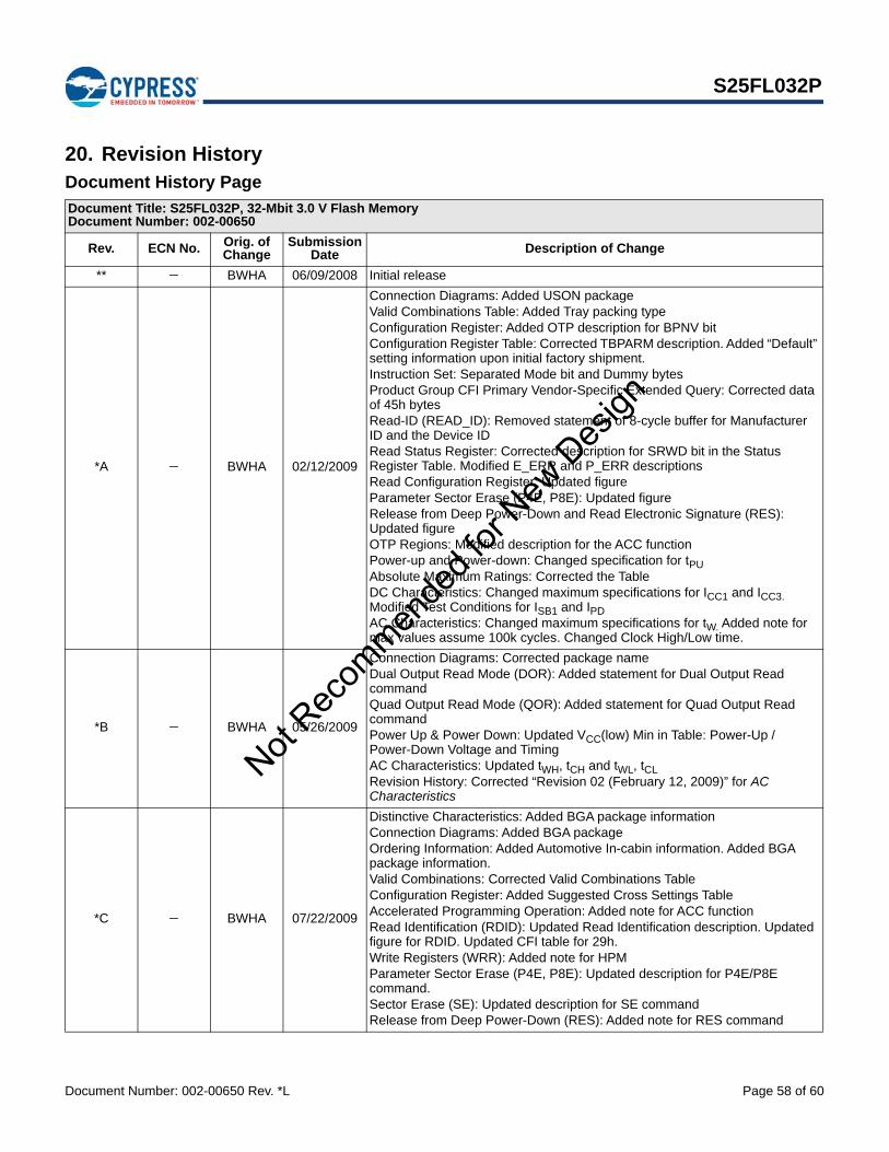
Document Number: 002-00650 Rev. *L Page 58 of 60
S25FL032P
20. Revision HistoryDocument History Page
Document Title: S25FL032P, 32-Mbit 3.0 V Flash MemoryDocument Number: 002-00650
Rev. ECN No. Orig. of Change
Submission Date Description of Change
** BWHA 06/09/2008 Initial release
*A BWHA 02/12/2009
Connection Diagrams: Added USON packageValid Combinations Table: Added Tray packing typeConfiguration Register: Added OTP description for BPNV bitConfiguration Register Table: Corrected TBPARM description. Added “Default” setting information upon initial factory shipment.Instruction Set: Separated Mode bit and Dummy bytesProduct Group CFI Primary Vendor-Specific Extended Query: Corrected data of 45h bytesRead-ID (READ_ID): Removed statement of 8-cycle buffer for Manufacturer ID and the Device IDRead Status Register: Corrected description for SRWD bit in the Status Register Table. Modified E_ERR and P_ERR descriptionsRead Configuration Register: Updated figureParameter Sector Erase (P4E, P8E): Updated figureRelease from Deep Power-Down and Read Electronic Signature (RES): Updated figureOTP Regions: Modified description for the ACC functionPower-up and Power-down: Changed specification for tPUAbsolute Maximum Ratings: Corrected the TableDC Characteristics: Changed maximum specifications for ICC1 and ICC3. Modified Test Conditions for ISB1 and IPDAC Characteristics: Changed maximum specifications for tW. Added note for max values assume 100k cycles. Changed Clock High/Low time.
*B BWHA 05/26/2009
Connection Diagrams: Corrected package nameDual Output Read Mode (DOR): Added statement for Dual Output Read commandQuad Output Read Mode (QOR): Added statement for Quad Output Read commandPower Up & Power Down: Updated VCC(low) Min in Table: Power-Up / Power-Down Voltage and TimingAC Characteristics: Updated tWH, tCH and tWL, tCLRevision History: Corrected “Revision 02 (February 12, 2009)” for AC Characteristics
*C BWHA 07/22/2009
Distinctive Characteristics: Added BGA package informationConnection Diagrams: Added BGA packageOrdering Information: Added Automotive In-cabin information. Added BGA package information.Valid Combinations: Corrected Valid Combinations TableConfiguration Register: Added Suggested Cross Settings TableAccelerated Programming Operation: Added note for ACC functionRead Identification (RDID): Updated Read Identification description. Updated figure for RDID. Updated CFI table for 29h.Write Registers (WRR): Added note for HPMParameter Sector Erase (P4E, P8E): Updated description for P4E/P8E command.Sector Erase (SE): Updated description for SE commandRelease from Deep Power-Down (RES): Added note for RES command
Not Rec
ommen
ded f
or New
Des
ign

Document Number: 002-00650 Rev. *L Page 59 of 60
S25FL032P
*C (Cont.) BWHA 07/22/2009
Operating Ranges: Updated descriptions. Added ESN1 and ESN2 Table.AC Characteristics: Added Automotive In-cabin spec for fC. Updated tWH, tCH and tWL, tCL.Physical Dimensions: Added BGA 6 x 8 mm package
*D BWHA 10/05/2009
Global: Changed all references to RDID clock rate from 40 to 50 MHzConnection Diagrams: Added “5 x 5 pin configuration” to Figure 2.5 title. Added 6 x 4 pin configuration BGA connection diagram. Added note regarding exposed central pad on bottom of package to the WSON and USON connection diagram.Ordering Information: Added Automotive In-Cabin temperature valid combinations for BGA packages. Added 02 and 03 model numbers for BGA packages. Removed BGA from 00 model number description. Added Low-Halogen material option.Valid Combinations: Changed valid BGA model number combinations to 02 and 03. Changed valid BGA material option to Low-Halogen.Removed Note 1.Physical Dimensions: Added FAC024 BGA packageAC Characteristics: Removed 76 MHz Automotive in-cabin spec from fC and Note 9.
*E BWHA 12/07/2011
Instruction Set Table: Updated QIOR commandPower-Up / Power-Down Voltage and Timing Table: Updated tPU (max)Initial Delivery State: Modified sectionCapacitance: Added notes to tablePhysical Dimensions: Updated the package outline drawing for SOIC, WSON, USON, and BGA 5x5 packages.
*F BWHA 09/21/2012 AC Characteristics: Changed Output Hold Time (tHO) to 2 ns (min).
*G BWHA 10/30/2012
Command Definitions: Instruction Set table: Corrected the value of CLSR commandWrite Registers (WRR): Protection Modes table: Added Parameter Sector Erase to Memory Content columns for clarificationParameter Sector Erase (P4E, P8E): Updated the table reference.
*H BWHA 01/29/2013 Capacitance: Added “Typical” values column. Corrected “Max” values for CIN / COUT (Input / Output Capacitance).
*I 4904072 BWHA 09/18/2015 Updated to Cypress template.
*J 5615358 ECAO 03/24/2017Corrected tCFT and tCRT positions in Figure 45 on page 50.Updated Cypress logo and Sales page.
*K 5711277 ECAO 04/25/2017
Added Valid Automotive Ordering Combinations in Section 5.1, Valid Combinations on page 9Updated all package outline drawings in Section 19., Physical Dimensions on page 52
*L 5742306 ECAO 05/19/2017Added Valid Automotive Ordering Combinations in Section 5.1, Valid Combinations on page 9.Added “Not Recommended for New Design (NRND)” status.
Document History Page (Continued)
Document Title: S25FL032P, 32-Mbit 3.0 V Flash MemoryDocument Number: 002-00650
Rev. ECN No. Orig. of Change
Submission Date Description of Change
Not Rec
ommen
ded f
or New
Des
ign

Document Number: 002-00650 Rev. *L Revised May 19, 2017 Page 60 of 60
© Cypress Semiconductor Corporation, 2008-2017. This document is the property of Cypress Semiconductor Corporation and its subsidiaries, including Spansion LLC ("Cypress"). This document,including any software or firmware included or referenced in this document ("Software"), is owned by Cypress under the intellectual property laws and treaties of the United States and other countriesworldwide. Cypress reserves all rights under such laws and treaties and does not, except as specifically stated in this paragraph, grant any license under its patents, copyrights, trademarks, or otherintellectual property rights. If the Software is not accompanied by a license agreement and you do not otherwise have a written agreement with Cypress governing the use of the Software, then Cypresshereby grants you a personal, non-exclusive, nontransferable license (without the right to sublicense) (1) under its copyright rights in the Software (a) for Software provided in source code form, tomodify and reproduce the Software solely for use with Cypress hardware products, only internally within your organization, and (b) to distribute the Software in binary code form externally to end users(either directly or indirectly through resellers and distributors), solely for use on Cypress hardware product units, and (2) under those claims of Cypress's patents that are infringed by the Software (asprovided by Cypress, unmodified) to make, use, distribute, and import the Software solely for use with Cypress hardware products. Any other use, reproduction, modification, translation, or compilationof the Software is prohibited.
TO THE EXTENT PERMITTED BY APPLICABLE LAW, CYPRESS MAKES NO WARRANTY OF ANY KIND, EXPRESS OR IMPLIED, WITH REGARD TO THIS DOCUMENT OR ANY SOFTWAREOR ACCOMPANYING HARDWARE, INCLUDING, BUT NOT LIMITED TO, THE IMPLIED WARRANTIES OF MERCHANTABILITY AND FITNESS FOR A PARTICULAR PURPOSE. To the extentpermitted by applicable law, Cypress reserves the right to make changes to this document without further notice. Cypress does not assume any liability arising out of the application or use of anyproduct or circuit described in this document. Any information provided in this document, including any sample design information or programming code, is provided only for reference purposes. It isthe responsibility of the user of this document to properly design, program, and test the functionality and safety of any application made of this information and any resulting product. Cypress productsare not designed, intended, or authorized for use as critical components in systems designed or intended for the operation of weapons, weapons systems, nuclear installations, life-support devices orsystems, other medical devices or systems (including resuscitation equipment and surgical implants), pollution control or hazardous substances management, or other uses where the failure of thedevice or system could cause personal injury, death, or property damage ("Unintended Uses"). A critical component is any component of a device or system whose failure to perform can be reasonablyexpected to cause the failure of the device or system, or to affect its safety or effectiveness. Cypress is not liable, in whole or in part, and you shall and hereby do release Cypress from any claim,damage, or other liability arising from or related to all Unintended Uses of Cypress products. You shall indemnify and hold Cypress harmless from and against all claims, costs, damages, and otherliabilities, including claims for personal injury or death, arising from or related to any Unintended Uses of Cypress products.
Cypress, the Cypress logo, Spansion, the Spansion logo, and combinations thereof, WICED, PSoC, CapSense, EZ-USB, F-RAM, and Traveo are trademarks or registered trademarks of Cypress inthe United States and other countries. For a more complete list of Cypress trademarks, visit cypress.com. Other names and brands may be claimed as property of their respective owners.
S25FL032P
Sales, Solutions, and Legal Information
Worldwide Sales and Design Support
Cypress maintains a worldwide network of offices, solution centers, manufacturer’s representatives, and distributors. To find the office closest to you, visit us at Cypress Locations.
Products
ARM® Cortex® Microcontrollers cypress.com/arm
Automotive cypress.com/automotive
Clocks & Buffers cypress.com/clocks
Interface cypress.com/interface
Internet of Things cypress.com/iot
Memory cypress.com/memory
Microcontrollers cypress.com/mcu
PSoC cypress.com/psoc
Power Management ICs cypress.com/pmic
Touch Sensing cypress.com/touch
USB Controllers cypress.com/usb
Wireless Connectivity cypress.com/wireless
PSoC® Solutions
PSoC 1 | PSoC 3 | PSoC 4 | PSoC 5LP | PSoC 6
Cypress Developer Community
Forums | WICED IOT Forums | Projects | Video | Blogs | Training | Components
Technical Support
cypress.com/support
Not Rec
ommen
ded f
or New
Des
ign