s the society for earthquake and civil e s e c e d
TRANSCRIPT

ISSN 0967-859XTHE SOCIETY FOR EARTHQUAKE AND CIVIL
ENGINEERING DYNAMICS
NEWSLETTERVolume 19 No 3
June 2006
SECED NEWSLETTER - JUNE 2006 - Page 1
SE
S E C E DED
Contents
Page 1 Protecting Structures from BombBlast
Page 5 Recent Advances in SeismicModel Testing
Page 9 EEFIT Mission to EarthquakeAffected Northern Pakistan
Page 12 Notable Earthquakes January –March 2006
Page 12 New SECED Website!
Page 12 Forthcoming Events
Protecting Structures from Bomb BlastPiroozan Aminossehe reports on this popular meeting.
SECED’s October 2005 eveningmeeting was a joint effort with theInstitution of Structural Engineers NorthThames Branch.
The subject of discussion was bombblast effects and how structures shouldbe protected against such loads. Ourtwo speakers were Professor GeoffMays and Dr Peter Smith fromCranfield University, Defence Academy
of the United Kingdom, who are botheminent in this field.
Not that long ago, such a topic was onlyrelevant for high-level securitystructures such as military or nuclearinstallations. However, due to recentevents particularly after 09/11, ourown problems on the 7th July andincreased terrorist activities, it seemsthat ordinary and conventionalbuildings are not safe either and can
also be easily targeted by terroristattacks and therefore it is quiteimportant that structural engineers
Figure 1 – Blast wave visualisation: 27 tonne trial Woomera, Sept 2002

SECED NEWSLETTER - JUNE 2006 - Page 2
who are involved in the design ofpublic buildings should have a goodunderstanding and knowledgeregarding such loads.
Due to our experience from theprevious blast conference two yearsago in October 2003 regarding theoverwhelming response and welcomewe received from engineers andspecialists in the field, we used a largerconference room and stil l theconference room was packed withpeople standing at the back. More than160 engineers and specialists camefrom different parts of the country, asfar afield as Manchester, Barrow inFurness and Glasgow.
The meeting commenced with anintroduction by PiroozanAminossehe, on behalf of SECED andcontinued under the co-chairmanshipof Thomas Lai, chairman of theInstitution of Structural Engineers,(North Thames Branch) and PiroozanAminossehe.
The first speaker was Dr Peter Smithwhose speech started with blastloading and continued with casehistories of blast effects and approachto structural analysis. This wasfollowed by Professor Geoff Mays’speech on the subject of principles ofstructural protection and guidelines forprotective design.
Dr Peter Smith described detonationas an explosive reaction proceeded bythe propagation of a high intensityshock wave through the explosivematerial at speeds of up to 9000 mm/s. The high pressure, hot gases soproduced expand violently, forcing thesurrounding air to ‘shock up’ and forma blast wave, as shown in Figures 1and 2.
Peter went on to describe the blastwave interactions with buildings andexplained that the reflected pressureand impulse is always greater than
incident pressure and impulse. He thenintroduced the definition of “ScaledDistance”, ‘Z’:-
3
1
W
RZ =
Where, Z is approximately a distancewhich debris may be expected to bethrown from an explosion.
R = range in metres from ‘sphericalfree air burst’ or ‘hemispherical surfaceburst’ charge.
W = Mass of charge in kilograms ofTNT (obtained by converting actualexplosive mass into ‘TNT equivalent’mass).
He went on to discuss internalexplosions and explained that theinternal blast was the concussion effectof pressure rise caused by rapidcombustion of fuel dispersed within aconfined volume of air, which could bequite damaging or even disastrous. Hecontinued that the internal blastspressure versus time consisted ofthree rather distinct regions. First ofthese is an initial pressure rise thatoccurs at a rate set by chemicalkinetics of the combustion reaction.The second part is the highreverberating blast pressure wavesfollowed by the pressure decay, whichis due to the cooling effects of confining
Figure 3 - 100kg Semtex detonated in three different situations but with rangeconstant in each case
Figure 2 Pressure vs time at a fixed location

SECED NEWSLETTER - JUNE 2006 - Page 3
Location of 200kg van bomb
�Solicitors �
IDB Building
walls together with ventilating effects.For example, peak impulse andduration of a blast for 100 kg of Semtexdetonating in three different situations,i.e., spherical, hemispherical andinternal with a constant range in eachcase are 532.4, 806.1 and 2059 kPa-msec and 15.3, 17.1 and 184.1 m-secrespectively, as shown in Figure 3.
Peter warned that, while the blastpressure for a single structuresubjected to a blast motion can beobtained using simple geometries suchas spherical or hemispherical, forcomplex geometries such as an arrayof city streets and buildings suchmethods may be deficient. For internaldetonations, rules are also available toestimate both reverberating blastwaves as well as the gas pressure loadfor relatively simple geometries.However, appropriate computerprograms, such as Air3d, should beused for complex conditions for bothexternal and internal detonations.
He then carried on that a structurecould resist a blast load, firstly, by beingmassive and offering a large inertialresistance, secondly, by beingdesigned from ‘resistive’ materialconfigured in a ‘resistive’ geometry andlastly by having ductile behaviour. Oneof the main reasons of catastrophicfailure of structures subjected to blastloading is lack of ductility, as shown inFigure 4.
He then said on many occasions astructure can be represented as onedegree of freedom and depending onthe ratio of the natural period of thesimplified model of the structure ‘T’ andthe duration of blast load t
d the following
type of solution can be offered:
• If T < td the blast loading can be
applied as quasi static loading;• If T > t
d the blast loading can be
applied as impulsive loading;• If T ~ t
d the blast loading can be
applied as dynamic loading.
It should be noted that in the abovescenario it is assumed that the appliedblast loading can be simplified as atriangular time history load where theheight of the triangle represents themaximum pressure and the base is t
d.
Figure 4 – Belfast 1985- ‘ductile’ vs ‘brittle’ structure.(Telephone warning at 1220, explosion at 1308. Casualties (8 wounded) low
because buildings evacuated).
Solicitor’spremises:post-blast
Debris throw andIDB building
RAC house - general view post-blast
RAC House
SECED NEWSLETTER - JUNE 2006 - Page 4
The analysis of the structure in order todefine the response of real structureelements from first principal is complex.However, Professor Biggs of MIT, duringthe 1950s and 60s, developed asimplified method called “EquivalentSystems”. The method is based on theassumption that a structural componentcan be approximately represented as anequivalent of one-degree freedomsystem, where its maximumdisplacement under the blast load isequal to the displacement of the one-degree freedom system subjected to thesame blast load. However, the responseof the equivalent system varies not onlywith the nature of the dynamic load butalso with the nature of the structure. Animportant aspect of the latter is theductility ration that corresponds to amaximum acceptable damage in someparticular blast situation. Charts havebeen developed for the equivalent staticload for a triangular pressure pulse as afunction of ductility ratio, pulse durationand natural period of the system.
At this stage Peter handed over toProfessor Geoff Mays whose subjectwas, “Principles of Structural Protectionand Guidelines for Protective Design”.
Professor Mays said the principles ofprotection within a new building againstblast hazard could be achieved throughlegislation, physical security, buildingarrangements and structural design.
Legislation addresses and regulates theessential requirements regarding safetyin use where the structures must bedesigned and built in such a way thatthey do not present unacceptable risksor accidents in service or in operation.
Physical security could be external and/or internal. External security consists ofitems such as CCTV, fencing and standoff. Internal security comprises itemssuch as alarms, detectors and search.
Good building arrangements, whichcould reduce the risk of blast hazard,consist of improving stand off andprotecting vital structural components bythe appropriate arrangement of externalphysical barriers and internalmanagement of assets.
He continued that it should be a balancebetween the cost of stand off andphysical hardening. By increasing the
physical hardening, the area of land usedfor stand off will be reduced. The cost ofthe stand off increases in proportion tothe square of its distance from thebuilding ‘R2’ and the cost of the physicalhardening increases in proportion to ‘1/R3’ On this basis the optimum distanceof ‘R’ can be estimated.
The protection of vital structuralcomponents is important, particularly inminimising the effects of fire. Pastcatastrophes have almost invariablybeen followed by fires and these becomemajor causes of building damage andloss of life. There seems to be no reasonto expect otherwise in possible futurecatastrophes.
In addition, the effects of blast should bemade less severe by variations toexternal building profile, and byconsidering how to protect people fromglazing hazards and from flying debris.
Geoff then turned his attention tostructural design and he emphasizedutilising the ductility within the structureby choosing appropriate materials aswell as the continuity within the structureby ensuring the structure possessessufficient redundancies. An importantitem in blast resistance structure is theuse of ductile materials for absorbingsome of the blast energy without thestructure being totally destroyed.Structural steel ordinarily is ductile; henceproperly designed steel structures arequite blast resistant. Concrete on theother hand is a brittle material unlessreinforcement bars are used, but withadequate reinforcements concrete
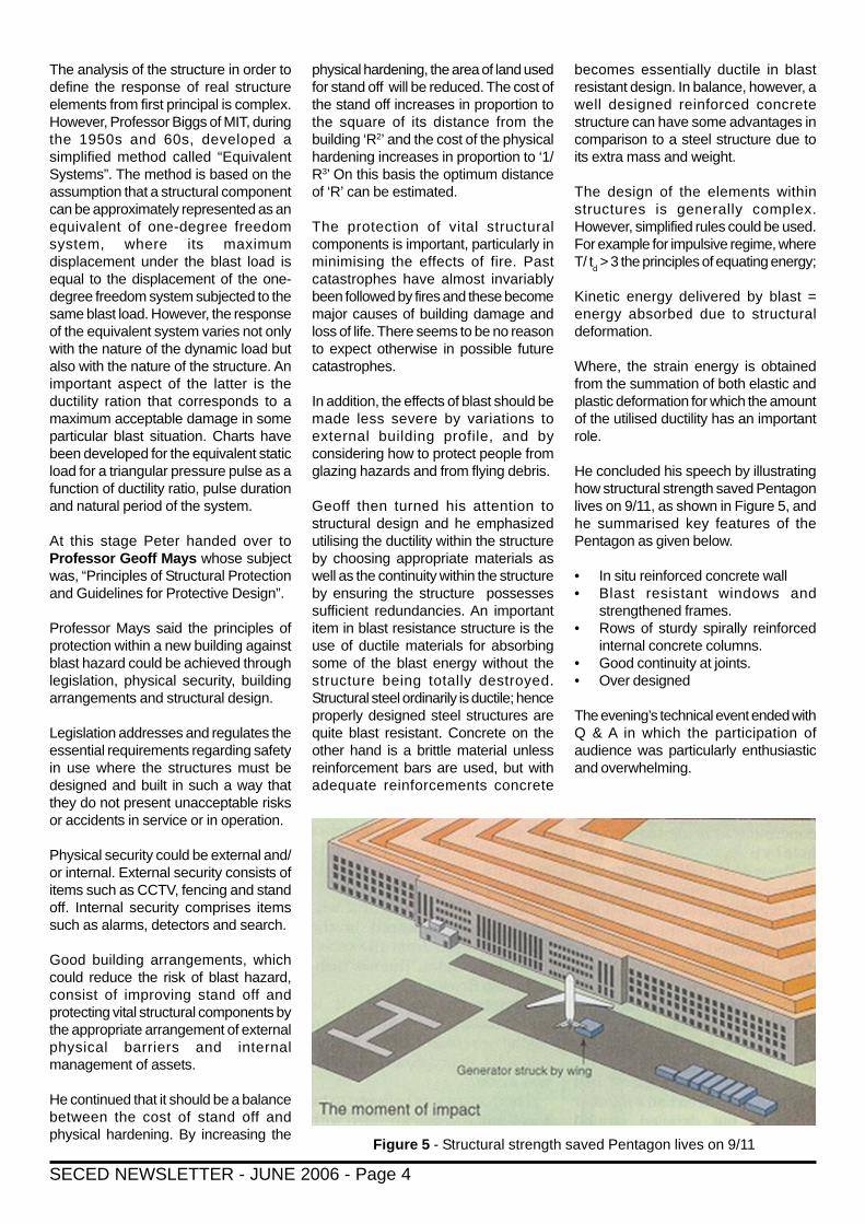
Figure 5 - Structural strength saved Pentagon lives on 9/11
becomes essentially ductile in blastresistant design. In balance, however, awell designed reinforced concretestructure can have some advantages incomparison to a steel structure due toits extra mass and weight.
The design of the elements withinstructures is generally complex.However, simplified rules could be used.For example for impulsive regime, whereT/ t
d > 3 the principles of equating energy;
Kinetic energy delivered by blast =energy absorbed due to structuraldeformation.
Where, the strain energy is obtainedfrom the summation of both elastic andplastic deformation for which the amountof the utilised ductility has an importantrole.
He concluded his speech by illustratinghow structural strength saved Pentagonlives on 9/11, as shown in Figure 5, andhe summarised key features of thePentagon as given below.
• In situ reinforced concrete wall• Blast resistant windows and
strengthened frames.• Rows of sturdy spirally reinforced
internal concrete columns.• Good continuity at joints.• Over designed
The evening’s technical event ended withQ & A in which the participation ofaudience was particularly enthusiasticand overwhelming.

SECED NEWSLETTER - JUNE 2006 - Page 5
Recent Advances in Seismic Model TestingAndrew Chan provides an account of the SECED meeting held last year at Bristol University.
1. BLADE facilitiesProf. Taylor began with an overview ofthe BLADE facilities. It is an infrastructureinvestment of 18.5 million pounds with15 million coming from the EPSRC JointInfrastructure fund and the remaining 3.5million coming from the BristolUniversity’s own investment.
The facility is shared by six departmentsin Bristol University. The construction ofthe building was completed in October2004 and the facility is expected to befully operational by Easter 2005. (Thefacility is effectively fully operational atthe time of writing)
The basic drivers behind the BLADEconcept is that the engineeringparadigms are changing. More andmore, the government is reluctant to fundinfrastructure renewal and expects theindustry to fund and carry the risk. Thisis coupled by similar new businessopportunities in the engineering industry.
In view of these changes in the industry,the vision of the BLADE facility is to
recognise that the real world isinterdisciplinary. There is a need toeliminate as many philosophical andphysical boundaries as possible.Therefore there is a need to promoteinterdisciplinary research.
Both dynamics engineering andengineering dynamics will beconsidered. While dynamics engineeringis the process of design and realisationof the dynamical performance of asystem, engineering dynamics are thescientific principles and theories ofdynamics on which dynamicsengineering depends. Both are commonto all engineering application domains.
Prof. Taylor then turned to an examplerelating to cracks in structural walls withopenings. Even though the relationshipbetween force parameter, damagestates and displacement seems to bevery simple in the above example,dynamic systems can be complex andchaotic when non-linear dynamicresponse is involved. The response issensitive to initial conditions, material and
numerical parameters. One of thepossible conclusions is that a few timehistory analyses will not be able tocapture the chaotic behaviour. Hesupported his argument with a numericalcalculated collapse diagrams for acracked masonry infill panel. Thediagram showed the number of cyclesto failure for different forcing frequencyand amplitude. With a small change offorcing frequency and/or amplitude, thenumber of cycles to failure can be totallydifferent. The resulting collapse diagramis a classical fractal one. The behaviouris totally different for different level ofviscous damping applied to the system.
He went on to challenge if the currentdisplacement based and capacityspectrum methods are adequate.Whether there are serious limitations inconsidering only force and displacementwhile neglecting velocity and possiblechaotic behaviour and fractal nature ofthe response. He argued that moreresearch is needed which would includelarge scale testing and rapid non-linearanalysis methods.
After that, he went on to introduce theBLADE facilities which include theEarthquake and large structureslaboratory, the shaking table and a highcapacity reaction wall. Lastly, Prof. Taylorexplained the management structure ofthe BLADE facilities which is driven byscientific themes. The laboratorymanagement would try to deliver sharedfacilities that satisfy the needs of theresearchers. The talk was followed by atour of the facilities.
2. The development of real-timesubstructure testingThe first speaker for the main technicalsession was Dr. Martin Williams whois a Reader in Structural Engineering,Department of Engineering Sciences in
The afternoon programme began with the welcome and introduction to BLADE (Bristol Laboratory for Advanced DynamicsEngineering) by Prof. Colin Taylor of Bristol University. It was then followed by a tour of the near-completed BLADE facilities.The weather [January 2005] was cold but a good attendance of approximately 40-50 was recorded. The audience was treatedto three high standard technical presentations on the topic “Recent Advances in seismic model testing”:
1. “The development of real-time substructure testing” by Dr. Martin Williams, University of Oxford.2. “Centrifuge” by Dr. Gopal Madabhushi of Cambridge University3. “Dynamic control” by Prof. David Stoten of Bristol University
Figure 1 Shaking Table

SECED NEWSLETTER - JUNE 2006 - Page 6
University of Oxford. His topic was “Thedevelopment of real-time substructuretesting”.
He also made the acknowledgementsthat significant contributions to the workin this presentation were made by AntonyDarby, Tony Blakeborough, DavidWilliams and Paul Bonnet. This piece ofwork was sponsored by EPSRC, TheLeverhulme Trust, EU and the Universityof Oxford
According to Dr. Williams, there are twomain types of Dynamic test methods:1. Shaking tables where one can applyprescribed base motion to models(Figure1).2. Pseudo-dynamic testing (Figures 2and 3) where Inertia and dampingcomponents are modelled numericallywith stiffness modelled physically.Hydraulic actuators apply calculatedseismic displacements and themeasured stiffness forces are fed backto numerical model.
According to the speaker, the trends forthe future are for the development of:
1. Very large shaking tables like the onein Japan;2. Fast “pseudo-dynamic” methodsincluding real-time substructure testingand effective force testing method.
The advantage of the shaking table isthat it can accurately reproduceearthquake input. However, unless oneis using a shaking table as big as thenew NIED (National Institute for Earth
equivalent earthquake induced inertialforces can be applied. Control of the loadcould become difficult if the structurebegins to fail or the direction of loadingchanges due to the change in thegeometry of the structure.
Real Time Substructuring (RTS)Starting with the externally appliedearthquake loading, the numericalsubstructure calculates thedisplacements at the interface betweenthe physical and numericalsubstructures. Then the magnitude ofdisplacements required is then translatedinto instructions to command theactuators to apply a load estimated toproduce the interface displacements forthe physical substructure. As the physicalsubstructure is loaded, the forces at theinterface and the actual displacement ofthe test specimen are then measured.The measured forces are then appliedto numerical substructure as well as anyexternal load for the next time step andthe process repeats itself until the endof the experiment. For a typicalexperiment, the time step is of the orderof 10 milliseconds.
The advantages of RTS testing includethe following:a. it avoids the physical scaling
problems associated with scaledmodel used in shaking tables
b. it avoids the time scaling problemsin pseudo-dynamic testing
c. it is ideal for testing rate-dependentsystems or components
d. it is economical as only the key partsneed to be modelled physically
Figure 2 Pseudo-dynamic testing Figure 3 Pseudo-dynamic testing - physical/numerical substructure interfaces
Science and Disaster Prevention)shaking table in Miki City, Japan, one isnormally limited to small-scale models.Then there are scaling problems in bothphysical dimension and time as well ascontrol problems. As for the large Mikitable, energy consumption and cost ofexperimentation could be a major issue.(Note: For comparison purposes, theMiki table has a payload of 1200 tonswith a maximum acceleration of 1.5g, themaximum displacement allowable is 1mand it is controlled by twenty four 450tonne actuators which are supplied byoil flow rate of 15,000 litre per min. TheBristol table has a payload of 15 tons.One must hasten to add that the Bristoltable can also test (smaller) full scalemodels.)
On the other hand, the advantage ofpseudo-dynamic testing is that it can beconducted at large scale. It is best suitedto test flexible structures withconcentrated masses. However, as ithas to be tested slowly, the expandedtimescale cannot capture any rate effectthat may be present. With the use offeedback loop in order to calculate thechange in force required, the error canaccumulate which can lead to majorinaccuracy or even instability in themodel.
The effective force testing inputs theequivalent earthquake induced inertialforces into the structure. However, inorder for this method to be applicable,the structure has to be simple in layoutand the mass must be concentrated atexternally accessible locations so that

SECED NEWSLETTER - JUNE 2006 - Page 7
e. it is fundamental to the developmentof multi-site tests where differenttesting facilities are used to modeldifferent parts of the overall structure.This approach is now being stronglypursued by the NSF NEES (Networkfor Earthquake EngineeringSimulation) programme in USA.
However there are a number ofrequirements before RTS can beperformed successfully. It requires highperformance hardware so that therequired numerical analysis can becompleted in real time. This has to becommunicated via fast, robust controland communications system to thephysical components in the substructure.Lastly software that is capable of fast andaccurate analysis of the numericalsubstructure.
The equipment set-up is as shown inFigure 4.
For tests with linear numerical model, afast solution of the dynamic equation isrequired.The equation system is first transformedvia modal decomposition into individualmodal shape and modal displacementto give individual modal equations. Thisis then truncated to eliminate the highermodes and the resulting equations aresolved by explicit integration.
However the resulting equation is notvery robust in practice and someimprovements have to be implementedto deal with experimental errors. So inorder to deal with the feedback ofdisplacement errors, the integrated formof equation is used instead. The mainproblem with this approach is in the delaydue to the actuator which isapproximately 0.01 second for theshaking table used and it has an effectequivalent to negative damping.Therefore a forward polynomialextrapolation scheme is used to correctthe displacement to be applied at theactuator.
On the other hand, a different algorithmis needed for the non-linear numericalmodel. Due to the non-linearity, thestiffness term will not decouple but theinertia and damping term still decoupleby modal decomposition. However theuse of a reduced modal basis will notaccurately model the non-linearbehaviour and a different basis is
needed. The new reduced basiscomprises of a subset of theeigenvectors as for the linear caseaugmented by a set of Ritz vectorsencapsulating the main non-linearities.
The issue of actuator delaycompensation has to be revisited asactuator delay varies (mostly increases)with the stiffness of the specimen. Theassumption of fixed delay can causeerrors or even instability, especially innon-linear or multi-actuator tests.Therefore, instead of using a fixed timedelay, the delay estimate is beingupdated using the adaptive procedureand the resulting position error of the newmethod is much smaller than one with afixed delay estimate.
3. Advances in physical andnumerical modelling inearthquake geotechnicalengineeringThe second talk was given by Dr. GopalMadabhushi, who is a Senior Lecturer,Cambridge University EngineeringDepartment and the Assistant Directorof the Schofield Centre. His topic was“advances in physical and numericalmodelling in earthquake geotechnicalengineering”.
His talk was organised into two parts withthe first part concentrating on the recentdevelopments in centrifuge modelling atCambridge and the second part focusingon their experiences in numerical
modelling using finite element method.He first introduced why centrifuge testingis necessary.
3.1 Earthquake ActuationIn order to simulate earthquake oncentrifuge, powerful actuators areneeded. These actuators need to workin the high gravity field of a centrifuge.These actuators also need to impart alarge quantity of energy to a model in avery short duration of time.
One of the latest developments inearthquake actuation technology ingeotechnical centrifuge research is theCambridge University Stored AngularMomentum (SAM) Earthquake Actuator.It is able to produce lateral shaking inthe centrifuge model. Energy is storedin a pair of flywheels then released tothe model via a fast-acting clutch. TheResultant acceleration is approximatelysinusoidal. The capabilities of the SAMearthquake actuator are summarisedbelow: (all given at prototype scale)
• g-level: Up to 100g• Frequency of Choice:1 to 5 Hz• Magnitude of Choice:Up to 0.4g (pga)• Duration of Choice: 2.5 to 100s
The advantages of the SAM system are:1.The shaking table system is able to
work at very high g-levels (> 100g)2. It produces relatively clean single-
frequency tone-bursts3. It is relatively inexpensive to
manufacturing
Figure 4 RTS Equipment set-up

SECED NEWSLETTER - JUNE 2006 - Page 8
However, it is only able to produce tone-bursts and swept-sine waves and notable to produce multi-frequency inputmotions.
Other new equipment recentlydeveloped or acquired include Fastdigital videography (1000 frames persecond at 1Mb resolution) in combinationwith PIV (Particle Image Velocimetry)analyses which is g-resistant but comewith a £50k price tag. The PIV principledepends on comparing patches in theinitial and the final images and calculatesthe degree of match in order todetermine the final position of the PIVpatch thus enabling the movement to becalculated.
3.2 Numerical modellingThe finite element programSWANDYNE was used for numericalanalyses of various problems. Theimportance of the choice of time step sizein coupled problems was established (toappear in Canadian GeotechnicalJournal). Results of Class C (after resultswere known) analyses of retaining wallsand Class A (before the experiment wasconducted) analyses of In-Situdensification of bridge foundations wereshown. The numerical modelling wascarried out hand-in-hand with centrifugemodelling. It is felt that for complexproblems such as the ones discussedhere, both centrifuge modelling and finiteelement based numerical analyses arecomplementary to each other.
4. Control of dynamicallysubstructured systemsThe third speaker was David Stoten,Professor of Dynamics and Control,Department of Mechanical Engineering,University of Bristol. His talk was on“Control of Dynamically substructuredsystems”
4.1 General introductionAn example of control of dynamicallysubstructured systems, via the MCSalgorithm can be found in vehicledynamics. While the emulated systemis, for instance, a complete racing car,only the physical component of the wheeland suspension is required to be tested,while the rest of the car is modelled usinga numerical model and the interactionbetween the physical and numericalsubstructure is controlled by an adaptivecontrol system so that the displacement
compatibility at the interface ismaintained using a change in the applieddisplacement. The change in applieddisplacement will result in a change inthe resulting force. This resulting forceis then fed into the numerical model andleads to a movement at the interface.This is adaptively controlled until thecompatibility is maintained between thenumerical and physical model.
MCS stands for ‘minimal controlsynthesis: and it is an adaptive controller.MCS has been development at Bristolsince around 1989, prompted by variousproblems in robotics
4.2 Dynamically substructuredsystemsThe advantages of the dynamicallysubstructured system includes:- Avoids the necessity of real-time
testing of an entire system. Instead,it allows for real-time testing of criticalcomponent(s) at full-size.
- Remaining non-critical componentsof the system are modellednumerically in real-time.
- This is a full-size testing method soproblems associated with similitudeand non-linear behaviour of small-scale model testing are avoided
- This is also a real-time physicaltesting method thus avoidingconvergence and stability problemsassociated with purely numericalmethods
- This is a real-time physical testingmethod thus avoiding problemsassociated with non real-timemethods such as pseudo-dynamictesting.
However, there are also some potentialdisadvantages including:- The synchronisation of physical and
numerical components is critical soexcellent control algorithm isrequired;
- There are problems to be solved:o The establishment of a
generalised dynamicsubstructuring framework andsynthesis issues for specificsystems
o closed loop stability androbustness issues
o signal noise and delay issues- Additional transducers are required
to link physical and numericalcomponents;
- Efficient real-time numerical modelsare required. Therefore efficienthardware, software andcommunications are required.
4.3 The Minimal control synthesis(MCS) algorithmThe Research studies Press (1990)version of the MCS algorithm is basedon a reference model. The output of thephysical plant for a given input iscompared with the reference model togenerate the error. Both this error andthe output of the physical plant togetherwith the input signal are fed into the MCSGain synthesis module. The gain on theinput signal and the gain on the outputfrom the plant are then controlled by theMCS module to adjust the input signalto the plant.
Later on in 2004, a new system calledMCS with error-feedback (MCS-E) wasproposed which is directly relevant to thecontrol of dynamically substructuredsystems. Instead of the combination oferror in output and the output of thephysical plant together with the inputsignal, only the error in output is fed intoMCS-E gain synthesis module. Insteadof the output from the plant, the gain onthe input signal and the gain on the errorare then controlled by the MCS moduleto adjust the input signal to the plant.
4.4 Synthesis of controllers fordynamically substructuredsystemsAn example of the Synthesis ofControllers for dynamically substructuredsystems is the substructured MIMOsuspension system with the emulatedsystem being a quarter-body roadvehicle. While the suspension ismodelled physically, the body, the wheeland the tyre are modelled numerically.
Various future works were mentioned atthe end and one of them was thegeneralisation of adaptive substructuringmethods for multi- and mixed-modesystems including shaking tables andreaction walls and frames.
The day was concluded with a shortpresentation which showed the Miki tablein action followed by a number ofquestions and answers.

SECED NEWSLETTER - JUNE 2006 - Page 9
IntroductionOn October 8, 2006 at 08:50 local time(03:50 UTC) an earthquake ofmagnitude 7.6Mw occurred in northernPakistan, which caused widespreaddestruction in Azad Jammu Kashmir(AJK) and in the eastern districts ofNorth West Frontier Province (NWFP).As of January 1, 2006, the totalcasualty figures in Pakistan alonestood at 72,763 deaths and 68,679injuries. Close to 400,000 homes werefully destroyed and damaged leavingabout 2.8million people without shelter.The heaviest damage occurred to thecities of Muzaffarabad and Balakot(Figure 1) that were nearest to the faultrupture responsible for the earthquake.Ground shaking was also felt in theIndian side of Kashmir and in someparts of northern Afghanistan.
The Earthquake Engineering FieldInvestigation Team (EEFIT) of theInstitution of Structural Engineers,London launched a field mission to theaffected areas in Northern Pakistanand Kashmir region of Pakistan onNovember 22, 2005. The team led byDr Navin Peiris (Arup) consisted of DrTiziana Rossetto (University CollegeLondon), Dr Paul Burton (University ofEast Anglia) and Mr Suqlain Mahmood(Sir Robert McAlpine). The missionstarted from Islamabad and visited theaffected areas of Abbottabad,Mansehra, Bagh, Balakot andMuzaffarabad (see Figure 1). The aimof the EEFIT mission was to observethe types of construction, constructionpractice and materials in order toidentify recommendations for futureconstruction, repair and retrofit
strategies and review of any existinglocal seismic-resistant design codes.They carried out walkover surveys andtook aerial photos of the damagedareas in order to identify the distributionand extent of damage to structures,road and bridges due to theearthquake. The team also studied thelandslides as these were a secondaryhazard to the earthquake causingdirect damage and disruption toinfrastructure and lifelines (e.g. roads),which inhibited post-disaster reliefefforts and the management ofrecovery.
Seismology and Fault LocationThe epicentral region lies on thewestern edge of the Himalayan Arc,which denotes the area of continental-continental convergence between the
EEFIT Mission to Earthquake Affected Northern PakistanBy Dr Navin Peiris (Arup)
Figure 1: Earthquake epicentre and aftershocks (USGS, 2005)
SECED NEWSLETTER - JUNE 2006 - Page 10
Indian and Eurasian tectonic plateswhere the Indian plate movesnorthward at a rate of 40mm/year andsubducts below the Eurasian plate. Theearthquake of magnitude 7.6Mw andfocal depth of 26km was followed bynumerous aftershocks of magnitudesbetween 4.0Mw and 6.0Mw over adistance of about 150km in the NE-SWdirection (see Figure 1).
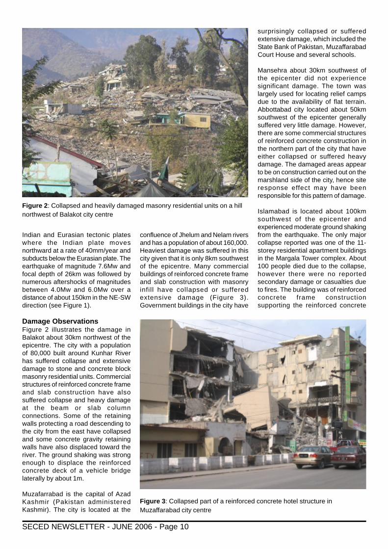
Damage ObservationsFigure 2 illustrates the damage inBalakot about 30km northwest of theepicentre. The city with a populationof 80,000 built around Kunhar Riverhas suffered collapse and extensivedamage to stone and concrete blockmasonry residential units. Commercialstructures of reinforced concrete frameand slab construction have alsosuffered collapse and heavy damageat the beam or slab columnconnections. Some of the retainingwalls protecting a road descending tothe city from the east have collapsedand some concrete gravity retainingwalls have also displaced toward theriver. The ground shaking was strongenough to displace the reinforcedconcrete deck of a vehicle bridgelaterally by about 1m.
Muzafarrabad is the capital of AzadKashmir (Pakistan administeredKashmir). The city is located at the
confluence of Jhelum and Nelam riversand has a population of about 160,000.Heaviest damage was suffered in thiscity given that it is only 8km southwestof the epicentre. Many commercialbuildings of reinforced concrete frameand slab construction with masonryinfil l have collapsed or sufferedextensive damage (Figure 3).Government buildings in the city have
surprisingly collapsed or sufferedextensive damage, which included theState Bank of Pakistan, MuzaffarabadCourt House and several schools.
Mansehra about 30km southwest ofthe epicenter did not experiencesignificant damage. The town waslargely used for locating relief campsdue to the availability of flat terrain.Abbottabad city located about 50kmsouthwest of the epicenter generallysuffered very little damage. However,there are some commercial structuresof reinforced concrete construction inthe northern part of the city that haveeither collapsed or suffered heavydamage. The damaged areas appearto be on construction carried out on themarshland side of the city, hence siteresponse effect may have beenresponsible for this pattern of damage.
Islamabad is located about 100kmsouthwest of the epicenter andexperienced moderate ground shakingfrom the earthquake. The only majorcollapse reported was one of the 11-storey residential apartment buildingsin the Margala Tower complex. About100 people died due to the collapse,however there were no reportedsecondary damage or casualties dueto fires. The building was of reinforcedconcrete frame constructionsupporting the reinforced concrete
Figure 2: Collapsed and heavily damaged masonry residential units on a hillnorthwest of Balakot city centre
Figure 3: Collapsed part of a reinforced concrete hotel structure inMuzaffarabad city centre

SECED NEWSLETTER - JUNE 2006 - Page 11
slabs with masonry infil l panelsseparating compartments. Thebuilding had an open basement usedas a parking garage and the wholebuilding was supported on a raftfoundation. The fact that adjacentbuildings did not suffer major damageto the structural load bearing elementssuggests that the collapsed buildingmay have been defective.
LandslidesLandslides were a major secondaryhazard in the earthquake affectedareas. Landslide activity resulted indamage to houses, commercialbuildings and most notable lifelines,which resulted in numerous casualtiesand disruption to the post-disasteremergency relief (Figure 4). Slidingfailures along slopes has createdinstability to buildings and roadsections at the top of the slope. Therewere many disrupted landslides, whichcould be triggered by anotherearthquake event or due to heavyrainfall or melting snow following thewinter months.
Socio-Economic ImpactThe estimated casualty figures as ofNovember 12, 2005 was 72,705deaths and 68,157 injuries from bothNWFP and AJK provinces (AsianDevelopment Bank data). Theearthquake left about 2.8million peoplewithout shelter creating the need toreconstruct about 400,000 homes forthe displaced population. The majorityof the victims were from the alreadyvulnerable groups, living incomparatively inaccessible mountainareas with lower levels of incomecompared to the national average.Many of the victims were women andchildren since women were caughtunaware in houses when theearthquake occurred and the collapseof school buildings resulted in deathsof many school children. The damageto housing, health and educationinfrastructure had a profound socialimpact on the region.
The earthquake has resulted in assetlosses amounting to US$2.3 billion withthe housing sector accounting forUS$1.0 billion worth of damage. Thereconstruction cost of all assets isestimated to be US$3.5 billion, whichconsiders the replacement cost of the
damaged assets and the additionalcost to be incurred due to seismicresistant design. The economic sectorsmost affected by the earthquake areagriculture, livestock, industry andservices. The impact on Pakistan’sofficial GDP has been estimated to beminimal.
ConclusionsThe earthquake resulted in substantialdamage to residential, commercial andgovernment buildings such as schools,hospitals and administration buildings.The damage may be attributed to thelack of seismic resistant design andconstruction practices in the region.There is therefore a clear need toeducate the local population during thereconstruction process in order tominimize the vulnerability from futureearthquake event. There is a need tocarry out a detailed seismic hazardassessment in order to identify theground motion levels in the region forreconstruction. It is advisable to carryout a multi-hazard risk assessmentinvolving earthquake, flood andlandslide hazards for appropriate siteselection for reconstruction. Althoughthe impact on the national economicoutput is considered minimal, there aresevere social consequences from thisearthquake given that the affectedprovinces record the highest level ofpoverty in the whole country.
Figure 4: Landslide blocking the road to Balakot from the north (Photo: US Army)

SECED NEWSLETTER - JUNE 2006 - Page 12
SECED NewsletterThe SECED Newsletter is publishedquarterly. Contributions are welcome andmanuscripts should be sent on a PCcompatible disk or directly by Email.Diagrams, pictures and text should be inseparate electronic files.
Copy typed on paper is also acceptable.Diagrams should be sharply defined andprepared in a form suitable for directreproduction. Photographs should behigh quality (black and white prints arepreferred). Diagrams and photographsare only returned to the authors onrequest.
Articles should be sent to:
John Sawyer,Editor SECED Newsletter,c/o The Secretary,SECED,Institution of Civil Engineers,Great George Street,LondonSW1P 3AA, UK.
SECEDSECED, The Society for Earthquake andCivil Engineering Dynamics, is the UKnational section of the International andEuropean Associations for EarthquakeEngineering and is an affiliated society ofthe Institution of Civil Engineers.
It is also sponsored by the Institution ofMechanical Engineers, the Institution ofStructural Engineers, and the GeologicalSociety. The Society is also closelyassociated with the UK EarthquakeEngineering Field Investigation Team. Theobjective of the Society is to promote co-operation in the advancement ofknowledge in the fields of earthquakeengineering and civil engineeringdynamics including blast, impact and othervibration problems.
For further information about SECEDcontact:The Secretary,SECED,Institution of Civil Engineers,Great George Street,London SW1P 3AA, UK.
SECED WebsiteVisit the SECED website which can befound at http://www.seced.org.uk foradditional information and links to itemsthat will be of interest to SECEDmembers.Email: [email protected]
NOTABLE EARTHQUAKES JANUARY – MARCH 2006Reported by British Geological Survey
YEAR DAY MON TIME LAT LON DEP MAGNITUDES LOCATIONUTC KM ML MB MW
2006 2 JAN 06:10 60.93S 21.58W 10 7.4 SANDWICH ISLANDS
2006 2 JAN 22:13 19.93S 178.18W 583 7.2 FIJI ISLANDS REGION
2006 4 JAN 08:32 28.16N 112.12W 14 6.6 GULF OF CALIFORNIA
2006 8 JAN 11:34 36.31N 23.22E 66 6.7 SOUTHERN GREECEThree people slightly injured and minor damage reported on Crete. Around 80 homes and an airport damagedon Kythira.
2006 12 JAN 19:03 51.30N 1.22W 15 2.6 BASINGSTOKE
2006 19 JAN 02:35 56.96N 5.61W 3 2.8 MALLAIG, HIGHLANDFelt in Mallaig, Glenfinnan and Lochailort (3 EMS).
2006 27 JAN 16:58 5.47S 128.13E 397 7.6 BANDA SEA
2006 2 FEB 12:48 17.75S 178.39W 598 6.7 FIJI ISLANDS REGION
2006 6 FEB 18:43 57.92N 5.50W 6 2.0 GRUINARD BAY
2006 14 FEB 00:55 27.34N 88.35E 30 5.3 SIKKIM, INDIATwo people killed by landslides at Sherathang and 2 more injured in East Sikkim.Minor damage to buildings and roads in the Gantok area.
2006 20 FEB 17:20 41.71N 25.54E 10 4.6 GREECE/BULGARIATwo people injured, over 175 buildings damaged and power and telephone service interrupted in the Murgovoregion, Bulgaria.
2006 22 FEB 22:19 21.25S 33.50E 11 7.0 MOZAMBIQUEFour people killed, 36 injured and around 300 buildings damaged or destroyed in the Espungabera and Beiraareas. Felt throughout Mozambique and Zimbabwe.
2006 28 FEB 07:31 28.13N 56.88E 18 6.0 SOUTHERN IRANSix people injured in Kahnuj and many buildings either damaged or destroyed in the Faryab and Baft areas.
2006 4 MAR 12:14 55.81N 5.71W 3 2.2 SOUND OF JURA
2006 7 MAR 18:20 23.77N 70.89E 10 5.5 GUJURAT, INDIASeven people injured and several buildings damaged in Jatawada.
2006 10 MAR 07:50 33.14N 73.95E 10 4.9 PAKISTANOne person killed and 22 others injured in Mirpur District.
2006 14 MAR 06:57 3.59S 127.21E 31 6.7 SERAM, INDONESIAOne person killed on Buru.
2006 20 MAR 19:44 36.60N 5.39E 10 5.0 NORTHERN ALGERIAFour people killed, 36 injured and 30 houses collapsed in the Kherrata area.
2006 31 MAR 01:17 33.60N 48.80E 10 6.1 WESTERN IRANAt least 66 people killed, 1200 others injured and many buildings damaged or destroyed in Lorestan Province.
2006 31 MAR 13:21 29.44S 176.75W 10 6.5 KERMADEC ISLANDS
Issued by: Davie Galloway, British Geological Survey, April 2006.Non British Earthquake Data supplied by: The United States Geological Survey.
3 to 8 September 2006First European Conference on EarthquakeEngineering and Seismology, Geneva
www.ecees.org
29 September 2006Earthquake Engineering in the 21st CenturyICE 6.00pm
25 October 2006Disaster Management
November 2006Stadia Dynamics
Forthcoming Events
Please visit our new-look website,www.seced.org.uk , which is theresult of much behind-the-scenesactivity over the last few months.
Your comments are welcome butplease bear with us as we iron outglitches and add content!
New SECEDWebsite!