rwedpa solid biomass cookstoves
TRANSCRIPT
Field Document No.44
REGIONAL WOOD ENERGY DEVELOPMENT PROGRAMME IN ASIAGCP/RAS/154/NET
FOOD AND AGRICULTURE ORGANIZATION OF THE UNITED NATIONSBangkok, September 1993
IMPROVED SOLID BIOMASS BURNING COOKSTOVES:
A DEVELOPMENT MANUAL
In Collaboration With
Asia Regional Cookstove Programmeand
Energy Research Centre of Panjab University, Chandigarh

This publication is printed bythe FAO Regional Wood Energy Development Programme in Asia,Bangkok, Thailand
For copies write to: Regional Wood Energy DevelopmentProgramme in Asia Tel: 66-2-280 2760c/o FAO Regional Offcie for Asia and the Pacific Fax: 66-2-280 0760Maliwan Mansion, Phra Atit Road, E-mail: [email protected], Thailand Internet: http://www.rwedp.org
The designations employed and the presentation of material in this publication do not implythe expression of any opinion whatsoever on the part of the Food and Agriculture Organiza-tion of the United nations concerning the legal status of any country, territory, city or area orof its authorities, or concerning the delimitations of its frontiers or boundaries.
The opinions expressed in this publication are those of the author(s) alone and do not implyany opinion on the part of the FAO.

FOREWORD
For more than 15 years development organizations, research institutes and hundreds of volunteersand specialists have been engaged in the development, testing and dissemination of improved cookstovesthroughout the developing world of Asia, Africa and Latin America. Conceived as a major way to combatdeforestation, increased efficiency of domestic cooking stoves was the major focus of researchers and hightargets of dissemination the concern of forest officials. Unfortunately, not all programmes lived up to theexpectations raised, a major reason being the lack of adequate attention to social, economic and institutionalissues related to introducing improved cookstoves. Based on the earlier experiences a new approach hasbeen adopted in many countries in which improved cookstoves are more integrated into the overallobjectives of rural and urban development. This is reflected in the broad range of sectors becominginvolved in ICS introduction, e.g. energy, forestry and health sectors, women in development and ruraldevelopment.
On the scientific side, considerable progress has been made with matching scientific theories ofefficient combustion with the needs of easy installation, use and maintenance. Many reviews andassessments of ICS programmes have also contributed to a better understanding of the key factors in theirsuccess. As a result of all these efforts there are now thousands of publications and articles on improvedcookstoves. This large amount of information has been useful for ICS experts, but not always for field staff,who need a comprehensive and informative document that covers all major issues of ICS introduction.
The Regional Wood Energy Development Programme in Asia (RWEDP) from its very beginning in1985 has given much attention and resources to the introduction of ICSs in its member countries. Severalworkshops and seminars on various aspects of ICSs have been organized and recently three documents onnational ICSs have been published for China, India and Thailand.
During this period it has become quite clear that a key factor in the success of ICS introduction isthe commitment and knowledge of field staff. Often these field staff lack basic information on ICSdevelopment and dissemination. The present manual provides them an insight into the complexity and thepotential of ICS introduction. It has been written in such a way that it introduces the field worker to ICSswithin a relatively short period. It is hoped that young scientists and students of wood energy conversion willequally benefit from the manual.
The author of this manual, Prof. S.K. Sharma, Director of the Energy Research Centre andHonorary Dean of the Chemical Engineering College of Punjab University has taken up the challenge ofbringing together all relevant information on ICSs in a concise and comprehensive way. RWEDP wishes toexpress its deep appreciation for his contribution to ICS development and his tenacity in (lie preparation ofthis manual.
Dr. Aroon Choincharn, Wood Energy Conversion Specialist of RWEDP provided the developmentframework for the manual and technical support throughout the process of its preparation. Mr. AukeKoopmans of Green Fields, Thailand, and Harry Oosterveen of RWEDP assisted with reviewing and editingand Ms. Maria Nystr6m of the Lund Committee on Habitat Studies provided highly useful comments andinformation for chapter 7, "The kitchen: An integral part of the cooking system". Typing and text layout weredone by Ms. Panpicha Issavasopon and Ms. Navaporn Liangcheevasonthon of RWEDP. I thank them all fortheir commitment and for the high quality of the support provided.
The financial contribution and technical comments from the Asia Regional Cookstoves Programme(ARECOP) are also gratefully acknowledged.
We hope that the present development manual will stimulate interaction between the many ICS fieldworkers and scientists from Asia and elsewhere. Their comments, advice and/or additional contributionsmay become valuable inputs for a revised version which we intend to publish in due course.
Egbert PelinckChief Technical Adviser

ii
TABLE OF CONTENTS
Page
FOREWORD . . . . . . . . . . . . . . . . . . . . . . . . . . . . . . . . . . . . . . . . . . . . . . . . . . . . . . . . . . . . . . . . . . . . . . . iLIST OF FIGURES . . . . . . . . . . . . . . . . . . . . . . . . . . . . . . . . . . . . . . . . . . . . . . . . . . . . . . . . . . . . . . . . . viLIST OF TABLES . . . . . . . . . . . . . . . . . . . . . . . . . . . . . . . . . . . . . . . . . . . . . . . . . . . . . . . . . . . . . . . . . . . viiLIST OF SYMBOLS . . . . . . . . . . . . . . . . . . . . . . . . . . . . . . . . . . . . . . . . . . . . . . . . . . . . . . . . . . . . . . . . . viii
1 TECHNOLOGIES FOR IMPROVED BIOMASS STOVES . . . . . . . . . . . . . . . . . . . . . . . . . . . . . . . . . . 1
1.1 Development Background . . . . . . . . . . . . . . . . . . . . . . . . . . . . . . . . . . . . . . . . . . . . . . . . 11.2 Development Approach . . . . . . . . . . . . . . . . . . . . . . . . . . . . . . . . . . . . . . . . . . . . . . . . . . 21.3 Objectives of the Present Study . . . . . . . . . . . . . . . . . . . . . . . . . . . . . . . . . . . . . . . . . . . 3
2 HISTORICAL REVIEW OF COOKSTOVE DEVELOPMENT . . . . . . . . . . . . . . . . . . . . . . . . . . . . . . . . 4
2.1 Historical Perspective . . . . . . . . . . . . . . . . . . . . . . . . . . . . . . . . . . . . . . . . . . . . . . . . . . . 42.2 Earlier Perspective . . . . . . . . . . . . . . . . . . . . . . . . . . . . . . . . . . . . . . . . . . . . . . . . . . . . . . 52.3 Presen Perspectives . . . . . . . . . . . . . . . . . . . . . . . . . . . . . . . . . . . . . . . . . . . . . . . . . . . . 5
3 PRINCIPLE FOR IMPROVED COOKSTOVES DESIGN AND DEVELOPMENT . . . . . . . . . . . . . . . . 7
3.1 Definitions . . . . . . . . . . . . . . . . . . . . . . . . . . . . . . . . . . . . . . . . . . . . . . . . . . . . . . . . . . . . 73.2 ICS Design Perspective . . . . . . . . . . . . . . . . . . . . . . . . . . . . . . . . . . . . . . . . . . . . . . . . . . 83.3 Stove Classification . . . . . . . . . . . . . . . . . . . . . . . . . . . . . . . . . . . . . . . . . . . . . . . . . . . . . 83.4 Design Criteria . . . . . . . . . . . . . . . . . . . . . . . . . . . . . . . . . . . . . . . . . . . . . . . . . . . . . . . . . 9
3.4.1 Social factors . . . . . . . . . . . . . . . . . . . . . . . . . . . . . . . . . . . . . . . . . . . . . . . . . . 113.4.2 Stove power output and other related needs . . . . . . . . . . . . . . . . . . . . . . . . . . 123.4.3 Local resources . . . . . . . . . . . . . . . . . . . . . . . . . . . . . . . . . . . . . . . . . . . . . . . . . 123.4.4 Economic factors . . . . . . . . . . . . . . . . . . . . . . . . . . . . . . . . . . . . . . . . . . . . . . . 133.4.5 Environmental factors . . . . . . . . . . . . . . . . . . . . . . . . . . . . . . . . . . . . . . . . . . . . 13
3.5 Design Principle . . . . . . . . . . . . . . . . . . . . . . . . . . . . . . . . . . . . . . . . . . . . . . . . . . . . . . . 143.5.1 Combustion process . . . . . . . . . . . . . . . . . . . . . . . . . . . . . . . . . . . . . . . . . . . . . 143.5.2 Heat Tranfer . . . . . . . . . . . . . . . . . . . . . . . . . . . . . . . . . . . . . . . . . . . . . . . . . . . 143.5.3 Fluid flow . . . . . . . . . . . . . . . . . . . . . . . . . . . . . . . . . . . . . . . . . . . . . . . . . . . . . . 223.5.4 Material science . . . . . . . . . . . . . . . . . . . . . . . . . . . . . . . . . . . . . . . . . . . . . . . . 23
4 WOOD AND BIOMASS COMPOSITION, PROPERTIES AND COMBUSTION CHARACTERISTICS . . . . . . . . . . . . . . . . . . . . . . . . . . . . . . . . . . . . . . . . . . . . . . . . . . . . . . . . . 24
4.1 Biomass Composition . . . . . . . . . . . . . . . . . . . . . . . . . . . . . . . . . . . . . . . . . . . . . . . . . . 244.1.1 Cellulose . . . . . . . . . . . . . . . . . . . . . . . . . . . . . . . . . . . . . . . . . . . . . . . . . . . . . . 254.1.2 Hemicellulose . . . . . . . . . . . . . . . . . . . . . . . . . . . . . . . . . . . . . . . . . . . . . . . . . . 254.1.3 Lignin . . . . . . . . . . . . . . . . . . . . . . . . . . . . . . . . . . . . . . . . . . . . . . . . . . . . . . . . . 254.1.4 Minerals and Ashes . . . . . . . . . . . . . . . . . . . . . . . . . . . . . . . . . . . . . . . . . . . . . 26
4.2 Methods for Assessing Biomass . . . . . . . . . . . . . . . . . . . . . . . . . . . . . . . . . . . . . . . . . . 264.2.1 Proximate analysis . . . . . . . . . . . . . . . . . . . . . . . . . . . . . . . . . . . . . . . . . . . . . . 274.2.2 Ultimate analysis . . . . . . . . . . . . . . . . . . . . . . . . . . . . . . . . . . . . . . . . . . . . . . . . 28

iii
4.2.3 Calorific value . . . . . . . . . . . . . . . . . . . . . . . . . . . . . . . . . . . . . . . . . . . . . . . . . . 294.2.4 Rate of devolatilization . . . . . . . . . . . . . . . . . . . . . . . . . . . . . . . . . . . . . . . . . . . 294.2.5 Thermo-physical properties . . . . . . . . . . . . . . . . . . . . . . . . . . . . . . . . . . . . . . . 31
4.3 Wood Combustion . . . . . . . . . . . . . . . . . . . . . . . . . . . . . . . . . . . . . . . . . . . . . . . . . . . . . 314.3.1 Stage 1 combustion . . . . . . . . . . . . . . . . . . . . . . . . . . . . . . . . . . . . . . . . . . . . . 324.3.2 Stage 2 combustion . . . . . . . . . . . . . . . . . . . . . . . . . . . . . . . . . . . . . . . . . . . . . 334.3.3 Stage 3 combustion . . . . . . . . . . . . . . . . . . . . . . . . . . . . . . . . . . . . . . . . . . . . . 334.3.4 Combustion of productions of pyrolysis . . . . . . . . . . . . . . . . . . . . . . . . . . . . . . 334.3.5 Combustion reactions . . . . . . . . . . . . . . . . . . . . . . . . . . . . . . . . . . . . . . . . . . . . 354.3.6 Effect of moisture on combustion of wood . . . . . . . . . . . . . . . . . . . . . . . . . . . . 35
4.4 Combustion Controlling Factors . . . . . . . . . . . . . . . . . . . . . . . . . . . . . . . . . . . . . . . . . . 364.4.1 Physical and chemical properties . . . . . . . . . . . . . . . . . . . . . . . . . . . . . . . . . . . 364.4.2 Size and shape of fuel . . . . . . . . . . . . . . . . . . . . . . . . . . . . . . . . . . . . . . . . . . . 364.4.3 Primary and secondary air supplies . . . . . . . . . . . . . . . . . . . . . . . . . . . . . . . . . 374.4.4 Fuel/air ratio . . . . . . . . . . . . . . . . . . . . . . . . . . . . . . . . . . . . . . . . . . . . . . . . . . . 374.4.5 Temperature of flame . . . . . . . . . . . . . . . . . . . . . . . . . . . . . . . . . . . . . . . . . . . . 384.4.6 Fuel supply . . . . . . . . . . . . . . . . . . . . . . . . . . . . . . . . . . . . . . . . . . . . . . . . . . . . 384.4.7 Concluding remarks . . . . . . . . . . . . . . . . . . . . . . . . . . . . . . . . . . . . . . . . . . . . . 39
5 IMPROVED COOKSTOVE TECHNOLOGIES . . . . . . . . . . . . . . . . . . . . . . . . . . . . . . . . . . . . . . . . . . 40
5.1 Combustion in Small Enclosures . . . . . . . . . . . . . . . . . . . . . . . . . . . . . . . . . . . . . . . . . . 405.1.1 Design considerations . . . . . . . . . . . . . . . . . . . . . . . . . . . . . . . . . . . . . . . . . . . 42
5.2 Influence of Sub-system Design on Optimum Efficiency . . . . . . . . . . . . . . . . . . . . . . . 435.2.1 Fire-box/combustion chamber . . . . . . . . . . . . . . . . . . . . . . . . . . . . . . . . . . . . . 435.2.2 Grate . . . . . . . . . . . . . . . . . . . . . . . . . . . . . . . . . . . . . . . . . . . . . . . . . . . . . . . . . 475.2.3 Pot hole/rim design . . . . . . . . . . . . . . . . . . . . . . . . . . . . . . . . . . . . . . . . . . . . . . 485.2.4 Chimney . . . . . . . . . . . . . . . . . . . . . . . . . . . . . . . . . . . . . . . . . . . . . . . . . . . . . . 495.2.5 Baffle . . . . . . . . . . . . . . . . . . . . . . . . . . . . . . . . . . . . . . . . . . . . . . . . . . . . . . . . . 505.2.6 Connecting tunnels . . . . . . . . . . . . . . . . . . . . . . . . . . . . . . . . . . . . . . . . . . . . . . 515.2.7 Damper . . . . . . . . . . . . . . . . . . . . . . . . . . . . . . . . . . . . . . . . . . . . . . . . . . . . . . . 52
5.3 Cooking Utensils . . . . . . . . . . . . . . . . . . . . . . . . . . . . . . . . . . . . . . . . . . . . . . . . . . . . . . 535.3.1 Material characteristics . . . . . . . . . . . . . . . . . . . . . . . . . . . . . . . . . . . . . . . . . . . 535.3.2 Geometric factors . . . . . . . . . . . . . . . . . . . . . . . . . . . . . . . . . . . . . . . . . . . . . . . 545.3.3 Operating characteristics . . . . . . . . . . . . . . . . . . . . . . . . . . . . . . . . . . . . . . . . . 54
5.4 Stove Construction . . . . . . . . . . . . . . . . . . . . . . . . . . . . . . . . . . . . . . . . . . . . . . . . . . . . . 555.4.1 Criteria for selection of material(s), construction methods and
strategies . . . . . . . . . . . . . . . . . . . . . . . . . . . . . . . . . . . . . . . . . . . . . . . . . . . . 555.4.2 Construction problems and prospects . . . . . . . . . . . . . . . . . . . . . . . . . . . . . . . 565.4.3 Construction technologies . . . . . . . . . . . . . . . . . . . . . . . . . . . . . . . . . . . . . . . . 57
5.5 Improved Cookstove Testings . . . . . . . . . . . . . . . . . . . . . . . . . . . . . . . . . . . . . . . . . . . . 595.5.1 Why test cookstoves . . . . . . . . . . . . . . . . . . . . . . . . . . . . . . . . . . . . . . . . . . . . . 595.5.2 Criteria for testing . . . . . . . . . . . . . . . . . . . . . . . . . . . . . . . . . . . . . . . . . . . . . . . 595.5.3 Indices for testing . . . . . . . . . . . . . . . . . . . . . . . . . . . . . . . . . . . . . . . . . . . . . . . 595.5.4 Overall thermal efficiency testing methods . . . . . . . . . . . . . . . . . . . . . . . . . . . 605.5.5 Specific task fuel consumption or cooking test . . . . . . . . . . . . . . . . . . . . . . . . 625.5.6 Test selection criteria . . . . . . . . . . . . . . . . . . . . . . . . . . . . . . . . . . . . . . . . . . . . 645.5.7 Concept of efficiency . . . . . . . . . . . . . . . . . . . . . . . . . . . . . . . . . . . . . . . . . . . . 65

iv
6 ENVIRONMENT AND HEALTH IMPLICATIONS ON BIOMASS BURNING COOKSTOVES . . . . . 696.1 Environmental Issues . . . . . . . . . . . . . . . . . . . . . . . . . . . . . . . . . . . . . . . . . . . . . . . . . . 696.2 Health Effects Related to Domestic Biomass Fuel Burning . . . . . . . . . . . . . . . . . . . . . 696.3 Emission, Characteristics of Biomass Fuels . . . . . . . . . . . . . . . . . . . . . . . . . . . . . . . . . 726.4 Strategies for Improvement of Kitchen Environment . . . . . . . . . . . . . . . . . . . . . . . . . . . 75
6.4.1 Improved stove designs . . . . . . . . . . . . . . . . . . . . . . . . . . . . . . . . . . . . . . . . . . 756.4.2 Fuel upgradation . . . . . . . . . . . . . . . . . . . . . . . . . . . . . . . . . . . . . . . . . . . . . . . . 766.4.3 Ventilation improvement . . . . . . . . . . . . . . . . . . . . . . . . . . . . . . . . . . . . . . . . . . 766.4.4 Switching to other clean fuels . . . . . . . . . . . . . . . . . . . . . . . . . . . . . . . . . . . . . . 76
7 KITCHEN, INTEGRAL PART OF THE COOKING SYSTEM . . . . . . . . . . . . . . . . . . . . . . . . . . . . . . . 77
7.1 Kitchen Stove Nexus . . . . . . . . . . . . . . . . . . . . . . . . . . . . . . . . . . . . . . . . . . . . . . . . . . . 777.1.1 Stove functions . . . . . . . . . . . . . . . . . . . . . . . . . . . . . . . . . . . . . . . . . . . . . . . . . 797.1.2 Culinary functions . . . . . . . . . . . . . . . . . . . . . . . . . . . . . . . . . . . . . . . . . . . . . . . 79
7.2 Kitchen Design Considerations . . . . . . . . . . . . . . . . . . . . . . . . . . . . . . . . . . . . . . . . . . . 807.3 Kitchen Indoor Air Quality . . . . . . . . . . . . . . . . . . . . . . . . . . . . . . . . . . . . . . . . . . . . . . . 82
7.3.1 Ventilation and building materials . . . . . . . . . . . . . . . . . . . . . . . . . . . . . . . . . . . 837.3.2 Chimneys and hoods . . . . . . . . . . . . . . . . . . . . . . . . . . . . . . . . . . . . . . . . . . . . 83
8 IMPROVED COOKSTOVE AS COMBINED TECHNOLOGY . . . . . . . . . . . . . . . . . . . . . . . . . . . . . . 85
8.1 Multipot Hole Stoves . . . . . . . . . . . . . . . . . . . . . . . . . . . . . . . . . . . . . . . . . . . . . . . . . . . 878.2 Channel/Shielded Fire Stoves . . . . . . . . . . . . . . . . . . . . . . . . . . . . . . . . . . . . . . . . . . . . 888.3 Nozzle Type Stoves . . . . . . . . . . . . . . . . . . . . . . . . . . . . . . . . . . . . . . . . . . . . . . . . . . . . 908.4 Chimneyless Stoves . . . . . . . . . . . . . . . . . . . . . . . . . . . . . . . . . . . . . . . . . . . . . . . . . . . 92
9 FUTURE NEEDS FOR R & D . . . . . . . . . . . . . . . . . . . . . . . . . . . . . . . . . . . . . . . . . . . . . . . . . . . . . . . 95
9.1 ICS Monitoring and Evaluation . . . . . . . . . . . . . . . . . . . . . . . . . . . . . . . . . . . . . . . . . . . 959.2 Combustion . . . . . . . . . . . . . . . . . . . . . . . . . . . . . . . . . . . . . . . . . . . . . . . . . . . . . . . . . . 959.3 Heat Transfer . . . . . . . . . . . . . . . . . . . . . . . . . . . . . . . . . . . . . . . . . . . . . . . . . . . . . . . . . 959.4 Transient Heat Transfer Studies . . . . . . . . . . . . . . . . . . . . . . . . . . . . . . . . . . . . . . . . . . 969.5 Environmental Issues . . . . . . . . . . . . . . . . . . . . . . . . . . . . . . . . . . . . . . . . . . . . . . . . . . 979.6 Kitchen Design . . . . . . . . . . . . . . . . . . . . . . . . . . . . . . . . . . . . . . . . . . . . . . . . . . . . . . . . 979.7 Improved Utensils . . . . . . . . . . . . . . . . . . . . . . . . . . . . . . . . . . . . . . . . . . . . . . . . . . . . . 989.8 Improved Culinary Practices . . . . . . . . . . . . . . . . . . . . . . . . . . . . . . . . . . . . . . . . . . . . . 989.9 Stove Construction Materials . . . . . . . . . . . . . . . . . . . . . . . . . . . . . . . . . . . . . . . . . . . . . 989.10 Heat of Chemical Reaction . . . . . . . . . . . . . . . . . . . . . . . . . . . . . . . . . . . . . . . . . . . . . . 989.11 Improved Performance of ICS . . . . . . . . . . . . . . . . . . . . . . . . . . . . . . . . . . . . . . . . . . . . 999.12 Commercial Stoves . . . . . . . . . . . . . . . . . . . . . . . . . . . . . . . . . . . . . . . . . . . . . . . . . . . . 999.13 Biofuel Upgradation Techniques . . . . . . . . . . . . . . . . . . . . . . . . . . . . . . . . . . . . . . . . . . 999.14 Stove Testing, Standardisation and Quality Control . . . . . . . . . . . . . . . . . . . . . . . . . . . 999.15 Final Caveat . . . . . . . . . . . . . . . . . . . . . . . . . . . . . . . . . . . . . . . . . . . . . . . . . . . . . . . . . . 99
BIBLIOGRAPHY . . . . . . . . . . . . . . . . . . . . . . . . . . . . . . . . . . . . . . . . . . . . . . . . . . . . . . . . . . . 101
APPENDIX 1 CHIMNEYS AND NET POSITIVE SUCTION HEAD . . . . . . . . . . . . . . . . . . . 117

vi
LIST OF FIGURES
Page
Figure 3.1 Processes in stove design…………………………………………………………………... 8Figure 3.2 Design considerations for a stove…………………………………………………………10Figure 3.3 Conduction, convection, radiation and stored heat……………………………………...15Figure 3.4 Total power radiated by a black body as a function of the temperature……………… 18Figure 3.5 View factor versus the distance to the pot………………………………………………..18Figure 4.1 Properties of biomass……………………………………………………………………… 25Figure 4.2 Possible reaction pathways for thermal degradation of cellulose under rapid heating
conditions…………………………………………………………………………………… 30Figure 4.3 The fire triangle………………………………………………………………………………32Figure 4.4 Processes and temperatures in a burning piece of wood……………………………… 32Figure 4.5 Wood combustion……………………………………………………………………………34Figure 5.1 Isometric view of an improved cookstove…………………………………………………44Figure 5.2 Heat analysis SURBHI-U…………………………………………………………………...65Figure 6.1 Effect of carbon monoxide concentration in the atmosphere as a function of exposure
time for various conditions of labour………………………………………………………70Figure 6.2 Generalised representation of component interactions in a domestic heating
operation……………………………………………………………………………………. 75Figure 7.1 Circle diagram illustrating how components of meal preparation are related to each
other and to the general social context at different levels………………………………78Figure 7.2 Attributes of operations and independent components………………………………… 79Figure 7.3 Attributes of dependent components………………………………………………………79Figure 7.4 Culinary and related functions of a kitchen………………………………………………. 80Figure 7.5 Supporting equipment and articles also need a place in the kitchen…………………. 81Figure 7.6 Cross ventilated kitchens and the placement of stoves………………………………… 82Figure 7.7 "Miniskirt model" with upper part of bamboo and lower part of concrete blocks…….. 83Figure 7.8 The Cooking Window tested in Vietnam…………………………………………………. 83Figure 7.9 Hood from a pilot kitchen in Burkina Faso……………………………………………….. 84Figure 8.1 Illustrations showing multipot hole stove, channel type stove and nozzle type stove..86Figure 8.2 The Rohini three-pot stove………………………………………………………………… 88Figure 8.3 Channel efficiency as a function of channel length for various channel widths……… 89Figure 8.4 Mai Sauki wood stove……………………………………………………………………….90Figure 8.5 "Sudha", a single-pot pottery ICS…………………………………………………………. 91Figure 8.6 Thermal efficiencies and combustion characteristics of "Sudha" ICS………………… 92Figure 8.7 Priagni, a single pot metal ICS……………………………………………………………..93

vii
LIST OF TABLES
Page
Table 1.1 Sectoral energy consumption as a % of total for some Asian countries…………………1Table 2.1 Survey of importance of objectives for various ICS programmes (%)…………………... 6Table 3.1 Values of the constants C and n for some standard configurations…………………….21Table 3.2 Values of the constant of the forced convection equation for typical configurations…. 21Table 4.1 Properties and characteristics of oven dry biomass……………………………………... 26Table 4.2 Calorific value of wood at different moisture contents…………………………………… 27Table 4.3 Proximate analysis for some fuel types…………………………………………………… 28Table 4.4 Composition of pyrolysis products…………………………………………………………. 31Table 4.5 Density, conductivity and the thermal diffusivity of different wood species…………… 31Table 5.1 Qualitative effects of different factors on thermal and combustion efficiency………….41Table 5.2 Optimum height of the combustion chamber and vessel mounts 50Table 5.3 Properties of stove construction materials…………………………………………………56Table 5.4 Suggested mixtures of soil/sand…………………………………………………………… 57Table 5.5 Results of the thermal performance of various stoves……………………………………66Table 6.1 Mechanisms of principal health effects from major pollutants………………………….. 70Table 6.2 Typical air pollution emissions for fuels and combustion systems……………………... 73Table 6.3 Exposure of women and children to pollutants during cooking………………………….74Table 6.4 Ambient and occupational air quality standards…………………………………………..74Table 8.1 Effect of the wood burning rate on the pot heating rate…………………………………. 87Table 8.2 Variation of heat gained by individual pots with wood burning rate……………………. 89Table 8.3 Variation of efficiency and CO/CO2 with the pot height from the top plate…………….92Table 8.4 Thermal efficiencies and combustion characteristics of "Priagni" ICS………………….93Table A-1 Density of flue gases…………………………………….…………………………………118Table A-2 Effect of elevation on density of air…………………………………….…………………118

viii
LIST OF SYMBOLS
A area size m² Greek symbols[a] ash content -cp specific heat J/kg-K " thermal diffusivity m²/s[c] carbon content - " resistance coefficient -d diameter m $ thermal expansion coefficient l/KF view factor - ).. difference -f friction factor - , emissivity -Gr Grashoff number - 8 excess air factor -g constant of gravity m/S² 0 efficiency %Hf combustion/calorific value J/kg D density kg/m³HL latent heat of evaporation J/kg F Stephan-Boltzmann constant W/m²KHc chemical heat J/kg > power density kW/m²H head in m < volatile fraction -h height m < kinematic viscosity (p/p) m²/sh heat transfer coefficient W/m²K : viscosity kg/ms[h] hydrogen content - M volume of stoichiometric air m³/kgk thermal conductivity W/m -Km mass kg[m] moisture content - Indicesn amount of material molNu Nusselt number - a ambient[o] oxygen content - av averageP power W b boilingPr Prandtl number - c charcoalp pressure kg/m² cc combustion chamberQ energy, heat J ch chimneyq heat flux/transfer rate W des designr radial distance, radius m e ends thickness m va evaporationRe Reynolds number - f fuelt time s fb fuelbedT temperature K fl flameV volume m³ fo foodV volume flow m³/s g gasv velocity m/s i initial
od oven dryp potrad radiationres resistances simmeringw water

1
CountryCommercial
energyFuelwood and/or
charcoalResidues,dung, etc.
Total traditional energysources
Year and source
Domestic Others Dom. Oth. Dom. Oth. Dom. Oth. Tot.
Bangladesh 3.8 9.8 11.7 3.4 57.6 13.7 69.3 17.1 86.4 1981/BEPP, 1987
Bhutan 1.5 11.3 75.1 11.8 0.6 0.0 75.7 11.8 87.2 1988/FAO, 1991a
India --- --- --- --- --- --- --- --- 39.1 89/90 Est. 5)
Indonesia 12.6 33.1 50.9 3.5 --- --- --- --- 54.3 1979/WB 1980 3)
Myanmar 0.6 12.0 84.1 --- 2.5 0.8 86.6 0.8 87.4 1990/WB 1990a
Nepal 1.2 4.4 92.8 1.5 0.0 --- 92.8 1.5 94.4 1982/WB 1983a
Pakistan 7.1 40.1 41.2 11.6 1) 1) 41.2 11.6 52.8 1991/Ouerghi'92
Philippines 10.1 44.8 32.6 5.3 3.5 3.6 36.1 8.9 45.1 1989/WB 1992b
Sri Lanka 6.6 21.6 59.0 10.3 2) 2.3 59.0 12.6 71.8 1990/CEB 1990
Thailand 8.8 60.9 18.9 2.4 1.2 7.6 20.1 10.0 30.3 1988/NEA 4)
Vietnam 2.0 24.0 29.6 4.4 34.7 5.2 64.3 9.6 73.9 1988/FAO 1992a
Note: "Others" includes Industry, Transport, Agriculture, Commerce, Government as well as Other uses. Conversion losseshave not been accounted for. -- denotes "No data available" while 0.0 denotes "Negligible amount"
1) Residues are included under fuelwood2) Domestic fuelwood consumption apparently includes residues also3) The Domestic sector includes Government use as well as use by Commerce4) The Domestic use includes use by Commerce as well5) Estimate, based on WRI/UN data for commercial energy and unofficial World Bank data for traditional sources of energy.
Table 1.1 Sectoral energy consumption as a % of total for some Asian countries
1 INTRODUCTION
1.1 Development Background
In the past, traditional sources of energy such as fuelwood, charcoal, dung, etc. were the onlysources of energy used for all types of applications. It is only during the last 250 years that fossil fuels suchas coal, oil and gas and electricity have emerged as major sources of energy in most developed countries.However, nearly 75% of the world's population which lives in the developing countries continues to dependon the traditional sources of energy for most of their energy requirements. This is also evident from table1.1 which shows that in some Asian countries the traditional sources of energy accounted for about 60-90% of the total amount of energy consumed.
In particular, the domestic sector relies heavily on traditional sources of energy, mainly for cooking,for which traditional stoves are often used. These stoves are usually thermally as well as environmentallyinefficient and hence create drudgery and problems for the users. Field evidence from many countries inAsia, Africa and Latin America shows that the introduction of improved cookstoves (ICSs) has broughtconsiderable benefits to rural and poor urban households (Foley and Moss 1983, Foley et al 1984,FAO/RWEDP 1991, Ramakrishna 1991, Barnes et al 1992, etc.).

2
1.2 Development Approach
While recognizing that fuelwood saving and energy conservation are universally accepted asimportant issues, these rarely are the sole reason for users to start using an ICS. In fact, it is increasinglyrecognized that the introduction of ICSs has done little, if anything, to arrest deforestation and/orenvironmental degradation as these problems are much more complex and, as such, can not be solvedsimply by the introduction of an ICS. Nevertheless, due to the multiple social benefits ICSs bring to theusers, mainly women, many countries have decided to start and/or continue to pursue improved cookstoveprogrammes (ICPs). These benefits of ICSs include:
! Saving of fuels and, directly or indirectly, saving of time due to the stoves' higher thermalefficiency. Cooking can often be done faster while the saving of fuel implies that less time isrequired to acquire it and/or money spent to purchase it. For example, it has been estimated thatin Nepal nearly 200-300 person days (mainly women and children) per year per household arespent in the collection of wood (Singh et al 1984). With the use of an ICS, this period can besubstantially reduced and the time saved can be used productively for other purposes.
! More complete combustion and/or the use of a chimney results in less smoke and soot emittedfrom the fire which, in turn, makes the kitchen a healthier place in which to work. Smoke emittedfrom biomass combustion causes serious indoor pollution, which affects the health of the cooks,most of whom are women and children. It has been estimated that the concentration of some ofthe pollutants, emitted due to the combustion of biomass, may exceed 10-100 times the WHOlimits (Smith 1986). Exposure to smoke has emerged as one of the major concerns in the ruralareas of the developing countries (WHO 1992). With more complete combustion less soot isdeveloped and the cooking pots remain cleaner and, as a result, less time is needed to clean thepots.
! Additional benefits of ICSs include a reduction in safety hazards such as less exposure to heatresulting in a better work environment, better hygiene due to availability of hot water for washing,protection from burn injuries and fire, etc.
Besides the direct and indirect benefits for the users, there are also socio-economic benefits suchas providing job opportunities through the production, sale and maintenance of ICSs, etc. Thus it can beconcluded that ICSs can make a significant contribution in rural development provided that efficient anddurable stoves can be introduced which fulfil all, or most, of the requirements of the users and ultimatelybring with them improved standards of cooking and living for the majority of the people.
Studies have shown that the users of ICSs are also concerned about other important features ofcookstoves such as: low fuel consumption and emissions, low cost, quick cooking, convenience ofoperation and maintenance, flexibility to use existing kitchen utensils, fuel and cooking practices, ease ofpropagation of fire and control of heat without much supervision and safety of operation. Even thoughcooking is the major requirement of the user, there are other important applications of ICSs such as spaceheating, smoking food items and agriproduce to preserve them, and water heating both in the householdsector as well as in the small scale industrial sector like agro-industries, gur and khandsari establishments,etc. Hence, it is imperative that a unified design-development approach is used in the development ofefficient fuel combustion systems taking social, cultural, scientific, economic, ergonomic, and healthaspects into consideration.

3
1.3 Objectives of the Present Study
A vast amount of literature has appeared in the last 15 to 20 years, covering almost all aspectsof stove development, especially in the areas of hardware development and technologies (e.g. design,testing, stove material, stove production techniques, etc.). Unfortunately, much of it is widely scattered andit is difficult to get a good overview of the status of technological advancement in the stove field. This haslead to duplication of efforts and lack of coverage for certain subjects. In some cases, stove technologyhas become an academic and highly technical subject, far beyond the understanding of the commonresearch worker. Conversely, many stove promoters consider an ICSs to be a very low level intermediatetechnology and hence often introduce crude stove products to the people for use.
It is, therefore, considered that a concise but simplified treatise on scientific knowledge relating tobiofuel cookstove technologies, which could facilitate the work of a large number of junior and middle levelstove researchers, is sorely needed. This manual is an attempt to address such a need and endeavoursto provide a challenge to stove experts to improve on the technological developments explored herein.

4
2 HISTORICAL REVIEW OF COOKSTOVE DEVELOPMENT
2.1 Early History
Evidence, found from archaeological excavations at Chou Kutien in China, indicated that thePeking man (Homo erectus pekingnensis), who lived in caves some 400,000 years ago during the first iceage, knew how to use fire (Bronowski 1973). At that time, fire was presumably used mainly for warmthrather than for cooking. The application of fire to cook food became apparent some 100,000 years ago,in the early part of the Upper Palaeolithic Period. During that period, the aim of cooking perhaps was torender food into a more digestible form. The making and use of refined stone implements and the masteryof fire can be considered important steps towards human civilization which took off only about 12,000years ago, when man had begun domestication of some animals and cultivation of plants (Bronowski1973). With the passage of time, human tastes gradually developed and later became sophisticated withmany gastronomic innovations, the use of a wide range of food materials as well as cooking techniques.
During the earlier ages, cooking was presumably done over an open-fire with fuel arranged in apyramid configuration. This mode of cooking, primarily for roasting meat, had major drawbacks: dispersionof the flames and heat during windy conditions, a lack of proper control over the fire, exposure to heat andsmoke as well as fire hazards. However, at the same time, heat and smoke had also certain benefits suchas food preservation and/or protection against large animals, insects/rodents and providing warmth duringthe cold seasons.
A major step towards the evolution of other cookstoves was the development of pots of variousshapes and sizes. This necessitated the modification of the open-fire to create shielded-fires in order tobalance the pot over the fire. The simplest form of the shielded-fire was a three-stone arrangement inwhich stones were arranged at approximately 120 degrees to one another on level ground. Besides,allowing a cooking pot to rest firmly on it, this arrangement also partly saved the fire from the vagaries ofwind and slightly increased cooking efficiency. However, by and large, the three-stone fire still sufferedsimilar drawbacks as the open-fire.
Subsequently, the shielded-fire was changed to a U-shaped mud or mud/stone enclosure with anopening in the front for fuel feeding and combustion air entry. Three small humps (made of the same mudmaterial) were positioned at the top rim of the enclosure and acted as a pot rest, induction point ofsecondary air needed for better combustion of volatile matter and for the exhaust gas exit. In order toconserve heat from the hot flue gases and to enhance cooking productivity, additional pot holes were lateradded. These pot-hole enclosures were connected by a tunnel. All the above mentioned innovations inthe cookstove design were made mainly by the users in light of their own experiences. These innovationsdid increase the efficiency of the stoves to some extent, but health and other hazards remained.
Despite human evolution and the developments which have taken place in stoves and fuel, it isamazing, however, to observe that currently most of the estimated 75% of the people who live in thedeveloping world, are still largely employing the three-stone or the shielded-fire for cooking and usingtraditional sources of energy such as fuelwood and other biomass similar to their pre-historic ancestorsseveral thousand years ago. In many cases people have actually moved backward to the use ofagricultural residues and dung for fuel.

5
2.2 The Recent Past
In the early 1950's in India the first phase of ICS development started with technological attemptsto improve the design of biomass-fired stoves. Because of the appalling smoky working environment ofmany Indian kitchens in which women had to cook, improved multi-pot stoves were introduced (Raju1953). These stoves, which were of the high-mass and shielded-fire type, had a chimney to remove smokefrom the kitchen and had adjustable metal dampers to regulate the fire. Theodorovic (1954) was the firstto conduct controlled laboratory tests on biomass burning ICSs in Egypt, although he did not measure thethermal efficiency of the stoves. Systematic studies on measuring cookstove efficiency was conducted bySinger (1961) in Indonesia on a high-mass mud stove with similar design features to those introduced byRaju.
The oil crisis of the 1970's brought energy issues to the forefront once again and improvedcookstove programmes (ICPs) were considered as a solution to the fuelwood crisis as well as a meansto arrest deforestation and/or desertification. During this second phase of ICS development, extensiveresearch and development studies were undertaken and a more sound technical base was laid as a resultof detailed thermodynamic, heat transfer and aerodynamic studies. More systematic testing and designprocedures were gradually established. However, the major thrust was on fuel saving while the socio-economic and cultural aspects of cooking were largely missing. A large number of biomass burningimproved cookstove (ICS) models began to proliferate, especially from the laboratories in many developingand developed countries. For roughly 10 years, during the early 70's and 80's, various international donorshad a very strong influence on improved cookstove development promotion and assistance all over theworld, particularly in Asia, Africa and Latin America. Unfortunately, the impact of these aid programmesproved to be short lived. This was basically due to the inability of the programmes to meet the expectationsand actual requirements of the users, a lack of long term development objectives, systematic institutionalarrangements and appropriate local manpower development. Many ICPs could not sustain themselvesand as soon as the government/donor funding stopped, the programmes ceased to operate. Thoseprogrammes that survived, however, managed to get local government commitments for long termsupport.
During the third phase, which began as recently as the late 80's, the emphasis shifted towards theneeds of stove users based on lessons learned from the second phase. It was found that, in addition tothe above mentioned criteria, factors such as cooking comfort, smoke free kitchens, convenience andsafety in the use of the stove were considered by the users to be as important as fuel saving.
2.3 The Present
A recent global survey (Ramakrishna 1991) conducted by the Energy and Policy Institute of theEast-West Center, Hawaii, for the Energy Sector Management Assistance Programme (ESMAP) of theWorld Bank has shown that the goals for improved cookstove programmes, as shown in table 2.1, havesubstantially expanded and are now rather diverse. The results show that there appears to be a distinctpattern of prioritizing ICP objectives in different geographical regions. For example, the greatestimportance (83% of ICS programmes) was placed on smoke reduction in Southeast Asian countries whilethis had a lower priority in Latin America (56% of the ICS programmes). Increased fuel efficiency was ratedvery high in all four regions but very low in Latin America. On the contrary, an increase in the welfare ofthe poor and improvements in the status of women were ranked highest in Latin America. The results ofthis survey provide an interesting overview of the activities of ICPs in different parts of the world. One of

6
Objective LatinAmerica
West Africa East/CentralAfrica
South Asia SoutheastAsia
TOTAL
n = 16 n = 18 n = 48 n = 26 n = 12 n = 120
Increase fuel efficiency 44% 72% 79% 65% 75% 70%
Reduce smoke emissions 56 67 67 65 83 67
Reduce deforestation 56 83 50 46 42 54
Save money 37 56 67 23 42 49
Improve status of women 56 11 31 42 17 33
Increase welfare of the poor 69 17 27 23 25 30
Save time 25 44 29 27 25 30
Safety 44 11 29 27 8 26
Increase environmental awareness 25 39 23 19 17 24
Generate income 6 0 31 23 33 22
Save fuel in community 31 11 12 23 25 19
Skill development 37 6 14 15 17 17
Create jobs 6 0 25 15 25 17
Community and institutional development 37 neg. 10 27 25 16
Prevent soil degradation 19 17 12 19 8 15
Others 19 6 2 12 8 8
Note: The table shows the frequency with which the objectives were ranked “1” on a scale where 1 = Very important,2 = Important, 3 = Less important, 4 = Not important and 5 = No opinion.
Source: Ramakrishna, 1991
Table 2.1 Survey of importance of objectives for various ICS programmes (%)
the significant findings was that apart from the benefit of fuel and money savings, other benefits such assmoke reduction, time saving, safety in the kitchen, income generation, improved status of women,increased environmental awareness, etc. have also been included as programme objectives.
The regional expert consultation on ICS development held in Udaipur, India (FAO/RWEDP 1991),where the status of South Asian ICS programmes was reviewed, common problems and constraintsidentified and strategies and future directions discussed, resulted in four comprehensive sets ofconclusions and recommendations on issues related to: research and development, programmemanagement, policy and institutions, and involvement of women. The general consensus of the meetingwas that: “Future ICP programmes should follow a wider systems approach. Programmes should look atnot only the introduction of ICSs but also at improved kitchens, cooking practices, utensils and fuels.” Inaddition, the role of improved stoves in reducing harmful emissions and greenhouse gases throughcleaner combustion was also highlighted. In short the major concern, in the modern context, has beenfocused on indoor air quality, the linkage between the functionality of stoves and kitchens, and theelimination of cooking drudgery as well as the method of dissemination.

7
3 PRINCIPLES OF IMPROVED COOKSTOVE DESIGN AND
DEVELOPMENT
3.1 Definitions
In order to ensure a clear understanding of the information presented in this chapter, thedefinitions of some important terms that will be used in relation to the improved cookstove design and itsprinciples are explained below.
The improved cookstove or ICS, in this context pertains to the solid biomass fuel burning systemin which heat is produced, by combustion, for immediate use in domestic cooking. As will be discussedin the next section, ICSs can also perform other tasks, depending on the design purpose arising from theuser's needs. Such a stove may perhaps be termed an improved stove (IS) which can be used fornumerous applications, namely: cooking, food preservation/drying, domestic heating and other social andcultural activities.
Biomass fuel denotes solid biomass either in a raw or processed form. This includes fuelwood,charcoal, agri-residues, briquettes, etc. While fuelwood is generally preferred in domestic cooking, residuefuels in sticks, leaves, straw and granular forms are also increasingly used due to fuelwood scarcity. Aswill be discussed shortly in sections 4.1 and 4.2, each type of biomass fuel has different properties andburning characteristics.
Combustion is the process through which the fuel and air chemically interact at sustainableelevated temperatures. The combustion process is dependent on the physico-chemical properties of thefuel, quantity and mode of air supply, and the conditions of the surroundings. All these parameters arediscussed in sections 3.5.1, 4.3, 4-4. and 5.1.
Heat transfer is the process by which the heat generated from combustion is transferred (orpurposefully targeted) at a heat absorbing surface. However, it is only possible to transfer a part of the heatreleased on combustion to the food in the cooking vessel, while the rest is dissipated to the surroundingsby different mechanisms of heat transfer, namely: conduction, convection, and radiation. In a normalcookstove design, the losses to the surroundings are suppressed and the transfer of heat to the contentsof the pot is maximized. A detailed discussion is presented in section 3.5.2.
Fluid flow is the movement mechanism of fluid, like air, gases and vapours, through a mediumunder normal or artificial pressure. Knowledge of fluid flow principles is essential for understanding the flowof air and flue gases through the stove, flow passages, and chimney. The application of fluid flow principlesare required to understand the combustion process, convective heat transfer and the chimney draftmechanism.
Knowledge of material science plays an important role in the selection of materials for stoveconstruction. Properties of materials have an important bearing on durability, cost, method of construction,heat losses, safety, and the scale of the production system. Material issues are discussed in sections3.5.4, 5.4, and 5.5.

8
+))<NATURAL+)<CONVECTION)))))))1* .))<FORCED
+)<HEAT TRANSFER))))3)<CONDUCTION* .)<RADIATION** +)<LAMINAR/)<FLUID FLOW)))))))1* .)<TURBULENT*
PROCESS)))))))))))1 +)<MASS TRANSFER CONSIDERATIONS * /)<HEAT TRANSFER
/)<COMBUSTION)))))))1* /)<THERMODYNAMICS* .)<KINETICS** +)<THERMAL PROPERTIES.)<MATERIAL SCIENCE)3)<CHEMICAL PROPERTIES
Figure 3.1 Processes in stove design
3.2 ICS Design Perspective
The thermal performance of an ICS depends upon the efficiency of the heat conversion system,e.g. conversion of chemical energy of fuels into thermal energy. It also depends upon the efficiency withwhich the thermal energy produced is transferred to the delivery systems, especially the cooking vesseland its eventual transfer to the food being cooked.
Thus, an ICS designer should have a complete understanding of the complex interaction betweenthe different processes that take place in a cookstove, e.g. combustion, heat transfer and fluid flow. Someof these parameters are controllable while others are non-controllable and a stove designer should be wellaware of these factors. Figure 3.1 provides a conceptual process consideration for an ICS design. Adesigner should not look at the stove as an isolated device but should visualize it as a part of the broader“kitchen system”. The design of a cookstove, therefore, should aim at enhancing the overall productivityof the kitchen system, taking into consideration health, safety, sanitation as well as energy efficiency.Indoor air pollution is becoming a major global concern and the health and kitchen aspects of this, relatedto ICSs, are discussed in more detail in chapters 6 and 7.
3.3 Stove Classification
A large number of ICS models, based on different construction materials, fuel and end useapplications, have been developed during the last 10-15 years. A proper ICS classification is essential foridentifying a model suitable for a particular group of user, target area, method of production anddissemination, keeping in view the cooking requirements and the availability of construction materials andfuels. Accordingly, ICSs can be classified into various categories:
a) Function
Mono-function stoves. An ICS which performs primarily one function, such as cooking or any othersingle special function such as fish smoking, baking, roasting, milk simmering, etc.

9
Multi-function stoves. In many areas, apart from cooking, an ICS can also be used for otherpurposes or in combination, such as for water heating, room heating, fish/meat smoking,grain/flour roasting, simmering of milk, etc.
b) Construction material
ICSs are mainly made of single materials: metal, clay, fired-clay or ceramics and bricks or arehybrids in which more than one material is used for different important components. Classificationbased on the material helps in selecting an appropriate design on the basis of locally available rawmaterials, skills for fabrication and necessary production facilities (e.g. centralized/decentralized)in the target area. The cost of an ICS and its expected service life can also be reflected in thisclassification, including its portability.
c) Portability
On this basis, an ICS can be classified as fixed or portable. Metal and ceramic ICSs are normallyportable in nature and can be moved indoors or outdoors while clay/brick, clay/stone ICSs aregenerally high mass and thus are fixed. Stoves in this category can be further sub-divided intodifferent categories depending on the number of pot holes, e.g., single, double and triple.
d) Fuel type
The performance of different ICSs, having the same function and constructed with the samematerials, will ultimately depend on the type of fuel used. In some cases, an ICS may be renderedpractically inoperable when switching over to fuel types for which it was not constructed. Forexample, an ICS primarily designed for fuelwood would not perform at all with rice husks orsawdust. Similarly, an efficient charcoal ICS may perform very poorly with fuelwood oragri-residues. Four major types of ICSs, based on fuel classification, normally encountered are:charcoal ICSs, fuelwood ICSs, granular/loose agri-residue ICSs, stick-form agri-residue ICSs, cowdung cake ICSs, and briquetted biomass-fuel ICSs.
From the discussion above, it can be seen that the classification provides critical information ona number of ICS design issues such as end use applications, technology and its transfer, cost, durability,fuel compatibility, etc.
3.4 Design Criteria
A cookstove is best considered as a consumer-specific device. Both engineering and non-engineering parameters need to be taken into consideration in designing an appropriate ICS. This makesthe exercise much more complex when compared with the design of other types of engineering equipmentor of a kerosene burning stove. ICS design considerations can be classified into three major criteria,namely: social, engineering, and developmental & ecological. Interlinkages between these parameters,as presented by Verhaart (1983a), are shown in figure 3.2.
Most of the designers, particularly in the first phase of ICS development (1950-1970), asmentioned in section 2.2 tended to use the social approach and designs of improved features such

10
Figure 3.2 Design considerations for a stove
NEEDS
SAFETYHEALTH
LOCALRESOURCE
COMFORT
FOOD
PANS
TIME
FUEL WOOD
CHARCOAL
AGRICULTUREWASTE
MATERIAL
SKILLS CLAY
METAL
BURN HAZARDSTO CHILDREN
COOKINGPOSTURE
HOT WATER
PORTABLE
SMOKE
FIRE HAZARDS
AMOUNT &TYPE
NUMBER OFDISHES &PAN SIZES
NUMBER OFHOLES & HOLE
SIZES; (ORMORE STOVES
SIZE OFCOMBUSTION
CHAMBER
POWER OUTPUT
CONTROL
FUEL ECONOMYCHIMNEY
DAMPERS
GRATE
FINALDESIGN COST
HEIGHT &LOCATION
STOVE
SOCIAL (CUSTOMERS) CONSIDERATIONS ENGINEERING CONSIDERATION DEVELOPMENT&ECOLOGICAL CONSIDERATION
as chimney, damper and baffle were developed without first undertaking rigorous technical analysis. Asa result many of the cookstoves propagated low thermal efficiencies and did not provide any relief to theusers in terms of fuel saving. The damper also proved to be a major hurdle as its use was the cause ofa high rate of burn injuries and its disuse led to excessive fuel consumption.
The engineering approach was used by a large number of the ICS designers during the secondphase (1970-1980). Well engineered, complex designs showing high thermal performance in thelaboratory were developed. However, in these designs very little importance was given to traditionalculinary practices, social aspects, local resource availability and ICS maintenance, etc. A large number ofvery well-engineered ICSs developed using this strategy again failed to make a lasting impact. The mainreason for this failure was that most designs failed to satisfy the diverse cooking requirements of the userswho belonged to different socio-cultural milieux and lived in diverse geographical areas. For example, ina two-pothole ICS model developed by this author (Sharma 1989), the power output was equallydistributed in both combustion chambers to ensure simultaneous cooking on both pot holes. The designwas thermally efficient but it failed to a attract the users as more time and effort was required to cook ameal. Besides, puffing of the local bread on the first pot hole was inadequate. Based on this feedback,a new model Akash (FAO/RWEDP 1993a) with higher power output on the first pot hole was developedin 1991. It has been widely accepted by the users and about 30,000 units have been disseminated so far.The third phase, from the late 80's onwards, saw a progressive use of the unified design approach inwhich most, if not all, criteria were incorporated. These are further elaborated below.

11
3.4.1 Social factors
Two important social factors regarding the ICS design are the user's needs and the localresources. A stove designer must take into consideration various needs of the target group, such as:cooking tasks, cooking utensils, size of cooking operation, and some specific operational parameters.Cooking tasks can be divided into four categories based on cooking temperatures and cooking media(Verhaart, 1983a):
a) BoilingWater is used as a medium in this type of cooking. This sets the upper temperature limit of thismode of cooking at only 100EC. The mixture of food and water is brought to the boil and is allowedto simmer till the completion of exothermic reaction in the food. An initial period is designated asthe high power phase and the later period is known as the low power phase.
b) FryingOil is used as a medium in this type of cooking. The upper temperature limit of this mode ofcooking is dependent on the boiling temperature of the oil, which is generally between 200-300EC.Frying is a high power input process as cooking is to be completed normally in a short duration,otherwise the food may get burned.
c) BakingThis process can be accomplished either in an oven or on an open pan (e.g. puffed unleavenedlocal breads, like Indian chapatti, roti and rotla and nan of Pakistan). In an oven, heat is transferredby convection and radiation from the oven walls, while conduction is the heat transfer mode foropen-pan baking. It is also a high power input process.
d) GrillingIn this mode of cooking, heat is transferred to the food primarily through radiation and to someextent through convection. It is a very high power input process and hence an intense heat sourceis required.
In addition to the four different cooking tasks as identified by Verhaart, two more cooking tasks canbe identified:
e) SteamingIn many Asian societies, in particular among Chinese and Southeast Asians much food isprepared by steaming in which the operating temperature is very close to boiling temperature.High power input is preferred at the initial stage of cooking. After the boiling starts, a low powermode similar to simmering is normally used.
f) Pressure cookingWhile in many developing countries, pressurized cookers are expensive and have to be imported,in some developing countries they are being produced at low cost. The pressurized cooking modeis similar to boiling, except that the temperature is considerably above water boiling point. Theoperating period, however, can be as short as one third of the normal boiling practice, thus helpingto save considerable cooking time and cooking fuel, besides imparting improved flavours.

12
Though cooking techniques as described above appear simple, the actual cooking is still largelyan art and depends on the perception of the cook and cultural considerations. Nevertheless, anestablished norm for the cooking task will help in evolving stove designs and cooking vessels.
3.4.2 Stove power output and other related needs
Besides the cooking modes mentioned above, in designing an ICS, the heat requirement, cookingtime and frequency for a specific cooking operation also need serious consideration. Cooking timedepends on the quantity of food to be cooked and the stove power as well as the number of items to becooked. Power output and its mode of regulation on various pot-holes is optimized mainly on the basis ofthe requirements of the user. Pot and pan size and shape also have an important bearing on the designof the stove, especially on the heat transfer characteristics. A detailed discussion on cooking vessels canbe found in section 5.4.
Thus, it is extremely important to gather information on various needs of the user in terms ofculinary practices and type of vessels and pot sizes being used before undertaking the design exercise.
Further introduction of new features requiring operational skills on the part of users should be donewith care, as they can stand in the way of acceptability. For example, stoves with dampers, which requiredperiodic manipulation were rejected by the users and necessitated the development of damperless models(Sharma 1990c).
Apart from cooking there can be other related domestic operations on the same ICS such asspace heating, food processing, water heating for bathing and clothes washing, etc. The acceptability ofa new design can be enhanced if some of these daily chores could be accomplished utilizing a newdesign.
3.4.3 Local resources
Another important consideration in the design of a cookstove is the appraisal of locally availableresources, especially types of fuel available, construction material, infrastructure and skills for the ICSproduction and distribution system. Diverse biomass fuel mixes normally are used in the developingcountries for cooking such as fuelwood, charcoal, agricultural and animal residues and/or combinationsof these. A cookstove designed for fuelwood will not perform well with cow dung due to the low density ofthe fuel and excessive amount of ash produced on combustion.
The construction material has an important bearing on the design of the model. In a location wheremetal sheets are not available, it becomes necessary to design ICSs using other locally available materialssuch as clay, bricks, ceramics etc.
Local fabricating skills and the type of fabrication infrastructure available must be taken intoconsideration when designing a stove. In the absence of proper infrastructure, it may not be possible forthe local manufacturer to replicate intricate designs. This will have an important influence on thedissemination strategy. For example, on the basis of heat transfer considerations, ceramics appear as abetter construction material. However, lack of fabrication facilities and transportation bottlenecks in anumber of developing countries are major hurdles in adopting this strategy. On the other hand,involvement of potters, using traditional techniques, for fabrication of fired clay models in the villages will

13
be a much better option. This strategy will not only generate local employment but will also overcometransportation bottlenecks as well as a better interaction between the users and ICS manufacturers.
3.4.4 Economic factors
The cost of an ICS depends on the construction material and fabrication complexity. An extremelyefficient model will not find favour with the users if it is beyond their purchasing capacity. Such ICSs cannotpenetrate the market without the support of the government. This factor must be taken into considerationat the design stage itself.
The stove should be sturdy, so that frequent maintenance is not required. The design should besuch that the parts which need periodic cleaning are easily accessible and the parts susceptible to wearand tear are easily replaceable at a reasonable cost. In addition, these should be easy to replicate by localartisans, using traditional or simple tools.
The design of the stove should also take into consideration the cost involved in organizingproduction. For example, an intricate design that requires expensive machine tools for fabrication can bea difficult proposition in the target (rural) area. At the conceptual stage itself, a designer should know if thefinal product is to be built by the user, a craft person or a commercial operation. Commercial operationscan be divided into different categories, depending on the size and product range such as repair shop, oneperson production unit, traditional artisan (blacksmith/potter/metal sheet worker), medium size productionunit, and specialized product factories. The cost of the production system and its economic viability on thebasis of the delivery/dissemination must be taken into consideration while designing a cookstove.
3.4.5 Environmental factors
Thermal efficiency and combustion efficiency which may work against each other in some casesmust be taken into consideration in the design of the ICS. Many designers often concentrate on increasingthermal efficiency at the expense of combustion efficiency, thus creating environmental problems,especially in non-chimney models. Although, ICSs with a chimney are environmentally safe as far as thekitchen atmosphere is concerned (but not always to the outside environment), they are more costly anddifficult to design due to problems of excessive draft and of transportation bottlenecks as many chimneydesigns are fragile (e.g. asbestos cement and ceramic pipes).
Protection from fire and burn injuries must be given due attention in the design of an ICS. This canbe accomplished by the selection of proper construction materials, proper design of the cowl and otherparameters of the stove. Ceramic and metal designs require more safety precautions to avoid burn injurythan thick walled clay stoves. The design should not only take precautions against sparks and burns butshould give equal importance to stability against tilting while stirring the food during cooking, especially inthe portable stoves. For example, as per Indian Standard (IS:13152, see FAO/RWEDP, 1993a), a portablestove should be stable against a tilt of 15 degrees. Cooking comfort of the cook in terms of cookingposture and ergonomics are other important considerations. Some users prefer right hand cookingpositions while others may prefer left hand cooking positions. This consideration is important in theplacement of the fire-box position in the design of fixed models.
Meteorological conditions have an important bearing on the portability of the stove. During hot andhumid conditions, outside cooking is preferred while during cold weather conditions cooking is mainly done

14
indoors. Thus geographical and meteorological conditions should be given due consideration in the designof the ICS. Stoves which do not blacken the pots are preferred by the users as less cleaning is needed.
Based on the above discussion of the environmental factors, the need for a new developmentapproach which aims to improve the efficiency of the kitchen system rather than the stove alone isapparent. This can be done by using an integrated approach, taking all the above mentioned factors intoaccount. Further discussion on such an integrated approach to the design of cooking system can be foundin Chapter 7.
To conclude, at the conceptual stage of the design itself, a stove designer should take asmany as possible, if not all, of the above design factors into consideration.
3.5 Design Principles
As mentioned earlier, the thermal performance of an ICS system depends upon theefficiency of the heat conversion system e.g. the conversion of the chemical energy of a fuel intothermal energy, the efficiency with which the thermal energy produced is transferred to the cookingvessel, the system with which the combustion products move through an ICS and finally also thetypes of material used for the construction of the stove.
A designer therefore should have a complete understanding of the complex interactionbetween the different processes such as: combustion, heat transfer, fluid flow taking place in acookstove and how the material used for stove construction has an influence on these factors. Abrief resume with regard to these factors is presented in this section while reference is made tothose chapters or sections where the parameters are covered in more detail.
3.5.1 Combustion process
The combustion process is dependent on the physico-chemical properties of the fuel (size,shape, density, moisture content, fixed carbon content, volatile matter, etc.), quantity and mode ofair supply (primary and secondary air) and the conditions of the surroundings (temperature, wind,humidity, etc.). All these parameters are covered in detail in chapter 4.
3.5.2 Heat transfer
Only a part of the heat released on combustion is transferred to the food in the cooking pot. Forexample, it has been estimated that for cooking rice, in theory, an equivalent of about 18 gramsof wood per kilogram of cooked food is required to heat the rice and water to the boiling point aswell to provide the amount of heat necessary for the chemical reaction to cook rice. In practice,however, about 160 grams of wood is required to accomplish this task, even with improvedcookstoves. It is clear that a large part of the heat is lost to the surroundings through three distinctheat transfer mechanisms: conduction, convection, and radiation (see also fig. 3.3 a, b, c and d).In order to minimize the losses to the surroundings and maximize the transfer of heat to the foodin the pot a thorough knowledge of heat transfer mechanisms and their underlying principles isrequired to determine the reasons for the losses, how these losses can be reduced throughmodifications of the design of the cook stove, etc.

15
Figure 3.3 Conduction, convection, rediation and store heat. From: Baldwin 1986
a) Conduction
Molecules are closely packed in solids. Whenever there is a temperature gradient these moleculestend to distribute and equalize their kinetic energy by direct interaction. This mechanism of heat transferis known as conduction. In metals, heat is conducted additionally by the movement of high velocity freeelectrons from high temperature regions to low temperature regions, where they collide with and exciteatoms. In general, heat conduction by free electrons is more significant than adjacent atoms exciting eachother.
The transfer of heat through conduction can be calculated using the following equation (Fourierconduction law):

16
q ' &k × A × ()T)
)X(3.1)
q 'A × )T
1
h1%
)X
k%
1
h2
(3.2)
)Q ' m × cp ×)T (3.3)
where q is the rate of heat transfer, k the thermal conductivity, A the area, )X the thickness of the surfacethrough which the heat is conducted and )T being the difference in the temperatures of the hot and coldsides. )X/kA is called the thermal resistance.
However, the use of this equation alone for calculating the surface loss gives values which aremany thousands of times the actual values. This is due to the non inclusion of the resistance of the surfaceboundary layer of air as well as the resistance due to the dirt or the oxide layer in the above expression.With the inclusion of these resistances, the equation takes the form:
where 1/h1 and 1/h2 are the inner and outer surface resistances and h1 and h2 are convective heat transfercoefficients respectively. These will be discussed in detail in the next section.
The ability of a material to store heat is another important factor in conductive heat transfer. Thisis measured by its specific heat, which is the energy required to raise the temperature of 1 kg of its massby 1EC. The change in the total amount of heat stored )Q, when the temperature of the stove with massm is changed by )T, is given by the equation
where cp is the specific heat of the material of the stove.
It can be inferred from the above equations that massive stoves will warm up slowly, whilelightweight stoves will heat up and dissipate heat quickly. However, the lower heat loss from thick walls iscompletely offset by a greater absorption of heat due to the storage effect. Only a small part of this heatcan be recuperated as useful heat. Hence, thin walls are generally preferred if cooking is intermittent.Massive stoves have therefore an advantage if the cooking is carried out throughout the day.
It can be concluded from the above discussion that the thermal inertia of the stove is a directfunction of the specific heat and mass, while the rate of heat transfer is a function of thermal conductivity.Thus, in order to increase the rate of heat transfer to the pot material, a high thermal conductivity of thepot material is preferred. In other words, an aluminum pot will help in faster cooking as compared to firedclay pots. Similarly, in order to reduce losses from the walls, materials having a low thermal conductivitysuch as mud or clay are better. In the case of metal stoves, the application of an insulation layer cansubstantially reduce the losses. Regions of interest from the viewpoint of conduction are:
! Transfer of heat from the pots to the contents of the pot; ! Loss of heat through the stove walls; ! Transfer of heat from the flame to the interior of the wood; ! Storage of heat in wood, pot and its contents and the body of the stove.

17
Maximum wavelength '2897.8
Tmicrons (3.4)
q ' F × A × T 4 (3.5)
q ' Em × F × A × T 4 (3.6)
b) Radiation
Energy in the form of heat radiation is emitted by all bodies above the absolute temperature dueto molecular and atomic motion as a result of the internal energy of the material. The internal energy isproportional to the temperature of the body in the equilibrium state. The ability of an object to emit andabsorb radiation is given by its emissivity and absorptivity, which are usually functions of the wavelengthof the radiation. The emissivity and absorptivity of a black material are equal. Heat radiation is absorbed,reflected, and transmitted when these come in contact with any solid body. The radiation is emitted overa range of wavelengths. The emitted radiation has a maximum intensity at the wavelength given by Wien'slaw with T being the absolute temperature.
In a cookstove, as shown in fig. 3c, the regions of interest from the radiation point of view are:
! Radiation emitted by the flame; ! Radiation exchange between the inner walls, pot and the wood; ! Radiation loss to the atmosphere from the wall, pot, chimney, and the opening of the fire box.
From equation 3.4, it can be concluded that radiation emitted by the burning flame is in the range of thevisible spectrum while that emitted by the stove surfaces at lower temperature is in the range of infraredradiation. Burning black carbon particles in the flame make it luminous (yellowish) with luminous flamesemitting more radiation than the non luminous (bluish) flame such as from a charcoal fire. This is causedby the higher emissivity of the black carbon particles.
Radiation from the flame, which accounts for nearly 14% of the total energy released from the fire,plays an important role in heating the fuelwood. This accelerates the release of volatiles, that support theflame, thus partly controlling the rate of combustion. Hot glowing wood and hot walls of the combustionchamber also radiate heat which is absorbed by the cooking vessel.
The rate of heat transfer by radiation, which is one of the most important modes of heat transferin the combustion chamber is given by the Stefan-Boltzman law for black bodies.
where F is the Stefan-Boltzman constant, which is equal to 5.6697@10-8 W/m2 K4, A is the emitting area ofthe object in square meters, and T is its temperature in K.
Black bodies have an absorptivity equal to 1, regardless of wavelength. Such bodies areimpossible to find in actual practice. In actual practice, bodies behave as grey bodies, which absorb onlya fraction of radiation impinging on it. For these bodies, the Stefan-Boltzman law is modified as:
where Em is the emissivity of the material.

18
Figure 3.4 Total power radiated by a black bodyas a function of the temperature
Figure 3.5 View Factor versus the height to thepot
Energy intercepted by the pot ' Power emitted by the firebed × A × VF (3.9)
It can be inferred from these equations that the energy emitted by a body is strongly dependenton the temperature. An increase in temperature by just 10% increases the heat output by 50%. Anotherimportant parameter in radiative heat transfer is the View Factor (VF) between the emitting surface andthe absorbing surface. The View Factor is the fraction of energy emitted by one surface that is interceptedby the second surface. It is determined by the relative geometry of the two surfaces.
The total power radiated by a black body as a function of temperature and the View Factor versusthe distance between fire bed and pot/radius of fire are presented in figures 3.4 and 3.5 (Baldwin 1986).The energy emitted by the fire bed corresponding to its temperature is calculated from figure 3.4, while theView Factor is determined from figure 3.5. These graphs are extremely useful for designing the fire firebox of a cookstove.
The energy intercepted by the cooking pot from the fire bed can be calculated from the followingequation if the View Factor is known.
For example: Consider a pot with a diameter of 20 cm (r2) placed 9.5 cm (h) above the fire bed havingdiameter (r1) and cylindrical single pot stove having height above fire bed equal to 9.5 cm (h). The valueof the View Factor for values of h/r2 (0.95) and r2/r1 from fig. 3.5 is 0.8. This means that 80% of theradiation emitted by the fire bed strikes the pot bottom. From fig. 3.4, if the temperature of the fire bed isequal to 900EK, it will emit 0.40 kW/m2. Using equation 3.7, the energy intercepted by the pot is 1.0 kW.
Radiative heat transfer from the fire bed in a cookstove can be increased, either by increasing thefire bed temperature (by controlling the air supply to the fire bed) or by increasing the View Factor. The

19
q ' h × A × )T (3.7)
latter can be increased by either decreasing the distance between the pot and the fire bed or by increasingthe diameter of the pot. However, too small a distance between the pot and the fire bed will result inquenching of the fire resulting in incomplete combustion and increased emission of CO and hydrocarbons.
This distance should be more than the combined height of the fuel bed and the flame length.Flame length is dependent on the type of fuel. The fuels with high volatile matter will produce longerflames. The length of the flame can be reduced by generating turbulence through design innovations. Inthe case of cookstoves with chimneys, induced draft modifies the flame length. The distance between thefire bed and the pot should be optimized taking into account its effect on the emissions in naturallyventilated stoves as well as in the induced draft stoves.
c) Convective heat transfer
Convective heat transfer involves the transfer of heat by the movement of fluid (liquid or gas),followed by conductive heat transfer between newly arrived hot fluid and the matter. Depending on the typeof driving force involved in the movement of the fluid, heat transfer by convection takes place by twodistinct mechanisms. When movement of the fluid takes place as a result of the buoyancy force createdby the temperature difference, the phenomenon is known as natural convection. On the other hand whenthe fluid is forced to flow by a blower or a fan or by windy conditions, the phenomenon is known as forcedconvection.
Convective heat transfer is the predominant mode of heat transfer in cookstoves. Hot gases,produced from the combustion of fuel, heat the pot through convective heat transfer. The cooling of thestove and the heating of the space also takes place through this mechanism.
In convective heat transfer, fluid flow and heat transfer take place simultaneously. The theoreticalanalysis requires the solution of continuity, momentum and energy conservation equations simultaneously.This makes the solution complex. The problem can be simplified by introducing the concept of boundarylayer resistance. The boundary layer concept assumes that most of the resistance to the heat transfer ispresent in the thin boundary layer adjoining the solid surface and not within the solid material and flowinghot fluid. The velocity across this boundary layer varies from zero, at the wall, as a result of friction, to themainstream velocity, at its outer edge. The heat is rapidly carried away by the solid and the fluid mainstream, on respective sides of the boundary layer. The conductivity of the stagnant gas layer is very low,hence this is the controlling resistance, which limits the heat transfer from the flowing gas to the solidsurface, such as the pot on a cookstove.
The rate of heat transfer can be increased by reducing the resistance in this boundary layer. Thiscan be done by increasing the velocity of the gas stream which reduces the thickness of the boundarylayer, thus reducing the resistance to the conductive heat transfer across it to the solid surface. Even withthese simplifications, the solution of the resulting equations is still complex.
In natural convection the hot gas temperature decides the flow as well as the heat transfer rates,which in turn decides its temperature. This inter-dependence of the controlling parameters makes thetheoretical analysis of natural convective heat transfer extremely complicated. In order to circumvent thisproblem, an empirical approach is generally used for the analysis of convective heat transfer problems.In an empirical approach, the convective heat transfer is estimated using a general equation:

20
Nu ' C × (Gr × Pr)n (3.8)
Gr 'g × B × T × l 3
L2(3.9)
Pr ' µ ×Cp
k(3.10)
where q is the heat transferred from the hot gas to the solid surface (pot surface/wall surface in the caseof a cookstove), A is the area of solid surface across which the flow of heat takes place, h is the convectiveheat transfer coefficient, and )T is the difference between the temperatures of the hot gas and the solidsurface.
The heat transfer coefficient, h can be either determined experimentally or theoretically (in somespecific cases). The heat transfer coefficient can be calculated empirically using the Nusselt number. TheNusselt number is the ratio of the characteristic length of the system and the thickness of the localboundary layer. It is defined as hd/k, where h is the heat transfer coefficient, d is the characteristic lengthof the system, and k is the thermal conductivity of the fluid (hot gas). The characteristic length is a functionof the system configuration. For example, in the case of a flow through the cylindrical pot hole in acookstove, it is equal to the diameter of the pot hole. In the case of a flow between the two vertical walls,it is the distance between them. For flow over a free surface, as in the case of a stove surface, it is thedistance from the leading edge.
In the case of heat transfer by natural convection, generally encountered in naturally ventedcookstoves, the Nusselt number can be evaluated from the relation:
where Gr and Pr are the Grashoff and Prandtl numbers respectively which are defined as:
where g is the acceleration due to gravity, B the volumetric expansion coefficient (approx.= 1/T), T is thetemperature difference between the surface and the ambient, µ the viscosity of the fluid, k the thermalconductivity and L the kinematic viscosity. For flow over vertical cylindrical surfaces, the characteristiclength l is equal to the heoght.
In cookstoves the values of C and n are taken as 0.53 and 0.25 respectively. For otherconfigurations any standard text book on heat transfer can be consulted. However, data on actualsituations encountered in cookstoves are lacking and there is a need to undertake experimental work todetermine these constants.

21
Configuration Gr * Pr C n
Hot vertical plate 104 - 109
109 and more0.590.13
0.250.333
Horizontal plate, hot side up 105 - 107 0.54 0.25
Horizontal plate, hot side down 2*107 - 1010 0.14 0.333
Vertical parallel plate 2*103 - 105
2.1*105 1.1*1070.200.71
0.250.333
Table 3.1 Values of the constants C and n for some standard configurations
Re 'd × v × D
µ(3.11)
Nu ' Cf × Re x × Pr y (3.12)
Configuration Re Cf x y
Laminar flow parallel to a flat plate < 3*105 0.332 0.5 0.333
Turbulent flow over a flat plate > 3*105 0.664 0.5 0.333
Laminar plane stagnation 0.57 0.5 0.4
A-symmetric stagnation to flat plate 0.93 0.5 0.4
Table 3.2 Values of the constant of the forced convection equation for typical configurations.
In the case of forced convection, the Nusselt number is described by the equation:
with Re being the Reynold's number, which is the ratio of the inertial forces in the fluid and the viscousforces and is defined as:
where d is the diameter, v the velocity of the fluid, D the density of the fluid and µ the viscosity of fluid. Cf
is a constant and depends on the system configuration.
A critical value of the Reynold's number defines the transition from laminar to turbulent flow. Forflow in a pipe, the critical Reynold's number is 2,300, while for flow along a single wall the value is 5x10⁵.Values of the constant of the forced convection equation for some typical situations are given in table 3.2.For others, any standard book on heat transfer should be consulted.
In cookstoves, the regions of interest from a convective heat transfer point of view are (Baldwin1986):
! Hot gas plume from the fire; ! Stagnation point of plume on the pot;

22
D1 × A1 × V1 ' D2 × A2 × V2 (3.13)
Hst % Hdy % Hpo ' Htot (3.14)
! Wall jet along the pot bottom and or sides, where the hot gases flow outward and upwards; ! Flow through tunnels, chimney, over baffles, and in the gap between the pot and wall in the case
of stoves with pots; ! Outer hot surfaces of pots, stoves and chimney.
The convective heat transfer problems in a cookstove are complex as strongly accelerating flowswith varying temperature difference in the direction of flow are encountered. Hence, conventional solutionsfor hydro-dynamically and thermally stable flow give approximate results.
3.5.3 Fluid flow
A thorough knowledge of fluid flow principles is also essential for understanding the flow of air andflue gases through the stove and the chimney as well as for understanding how these influence thecombustion process, the transfer of heat from the hot flue gases to the pots in the different chambers andthe heat losses from the pots and the different stove components of the stove to the surroundings.
The induction of air required for the combustion of fuel in the combustion chamber and thesubsequent flow of the combustion products through various chambers and connecting tunnels isgoverned by the principles of fluid flow. The suction effect, responsible for the induction of air into thecombustion chamber, is created as a result of the flow of flue gases through the chimney. The amount canbe estimated by the application of principles of fluid flow. The steady state flow of fluid is governed by thecontinuity equation which is based on the principle of conservation of mass. According to this equation themass of fluid passing all sections per unit of time is constant. This can be represented by the followingequation:
where D is the density, A is the area and V is the velocity. This equation can be used to calculate thevelocity of the flue gases and air at different locations in the stove.
Based on the applications of conservation of energy to the flow of fluid, an equation known asBernoulli's equation can be derived. For the steady state flow of low pressure gas in which there is anegligible change in internal energy, the equation can be described as:
where Hst is the static head, Hdy is the dynamic head, Hpo is the potential head and Htot is the total frictionalhead. The head is expressed in meters and is equal to ÎP/D where ÎP is the pressure loss and D is thedensity. The potential head or Hpo is equal to Hz where z is the elevation above any given level in meters.All other parameters are discussed in detail in appendix 1.
In some cases a sudden expansion and contraction is encountered during the flow of flue gasesthrough the tunnels and the chambers. The frictional loss Hfr due to the sudden expansion of a duct witha cross sectional area of A1, where the mean velocity is V1 into a duct with a larger cross sectional areaof A2 where the velocity is V2 is given by the expression:

23
Hfr '(V1 & V2)
2 gc(3.15)
where gc is a conversion factor having a numerical value equal to the acceleration due to gravity.
3.5.4 Material science
The materials used to construct a stove have a distinct bearing on the durability, cost, heat losses,safety, the skills required to make a stove and the scale of production envisaged, etc. The stove designershould therefore have a good understanding of how the material influences these factors. Some of thematerial properties for cooking vessels are described in more detail in section 5.4, while material propertiesfor stove construction are presented in section 5.5.

24
4 WOOD AND BIOMASS COMPOSITION, PROPERTIES AND
COMBUSTION CHARACTERISTICS
4.1 Biomass Composition
Biomass is a term used to signify any kind of biomass in solid form used for fuel, especiallyfuelwood, charcoal, dung cake, agricultural and other biodegradable solid residues. It is the major sourceof fuel for domestic cooking and numerous rural applications in the developing countries. Biomass is theproduct of the photosynthetic reaction of carbon dioxide and water. It consists of three basic elements:carbon, oxygen and hydrogen, which are present in the complex macroscopic polymeric forms. Theseforms are:
Cellulose (C6H10O5)x,Hemicellulose (C5H8O4)y andLignin (C9H10O3(CH3O)0.9-1.7)z.
The composition of these constituents varies with the plant species. In the case of wood, forexample, hardwoods generally contain about 43% cellulose, 35% hemicellulose and 22% lignin, whilesoftwoods contain nearly 43% cellulose, 28% hemicellulose and 29% lignin (Shafizadeh and De Groot1976). Biomass consists of three major elements: carbon, oxygen and hydrogen with the approximateproportion of about 50% C, 6% H and 44% O on a moisture and ash free basis. In general it can berepresented by the empirical formula of CH1.44 O0.66. Ash, with a few exceptions, is normally considered asa minor component in biomass. Further discussions on ash can be found in section 4.1.4.
The moisture content of biomass, in natural form, varies over a wide range from as 50% (on drybasis) for very dense hardwood species grown in arid areas to a few hundred percent for the very lightwood species grown in swamp or moist areas. In practice, biomass needs to be first dried to a levelpreferably in equilibrium with the working environment. The term equilibrium moisture content or EMC hasbeen used to denote that situation. For wood the natural EMC generally ranges from 7-15% dependingon agro-climatic conditions and season of the year. For more details, please consult "Water in Wood"(Skaar, 1972).
The heat of combustion of biomass based fuels is dependent on the percentage of the three mainconstituents. Lignin has the highest (26.63 MJ/kg), while holocellulose (cellulose and hemicellulose) hasa value of 17.46 MJ/kg. Therefore, wood with a greater percentage of lignin has higher heat of combustion.Coniferous (fir and pine) and a number of other wood species contain a considerable quantity of resinoussubstances that have much higher calorific values than lignin. The proportion of hydrogen and oxygen incellulose is the same as that in the water molecule, thus there is no contribution of hydrogen towards thecalorific value. The heating value of wood, therefore, depends on its carbon and resinous constituents(while keeping its moisture content constant). The combustion and pyrolytic characteristics of woodybiomass, as will be explained in later sections, depend on the relative proportion of the constituents,namely: cellulose, hemicellulose, lignin and in some cases the ash content. Physico-chemicalcharacteristics of these constituents, which have an important bearing on the combustion characteristics,are shown in figure 4.1 and are further described in the following sections.

25
WOODCHARCOAL
TYPE AGRICULTURAL RESIDUESANIMAL RESIDUESBRIQUETTES
SIZEPHYSICAL DENSITYULTIMATE ANALYSIS FUEL CHARACTERISTICS CHEMICAL PROXIMATE ANALYSISSPECIFIC HEATTHERMAL CALORIFIC VALUE
CELLULOSEHEMICELLULOSECONSTITUENTS LIGNINMINERALS/ASHES
Figure 4.1 Properties of biomass
4.1.1 Cellulose
Cellulose is a glucon polymer consisting of a linear chain of B(1,4)- glucopyranose units havingan average molecular weight of 100,000. A highly inert crystalline structure within the microfibrils isprovided by the aggregation of these linear chains. The behaviour of cellulose, when subjected to a hightemperature, is of great interest for understanding the combustion behaviour of biomass. It has been found(Shafizadeh 1982) that the pyrolysis of cellulose takes place in two stages, at temperatures below andabove 300EC. The main processes taking place below 300EC are: the reduction in the degree ofpolymerization; the appearance of free radicals; the elimination of water; and the formation of carbonyl andcarboxyl groups which are assumed to get converted to carbon monoxide and carbon dioxide with theformation of some char. During the second stage at temperatures above 300EC, the formation of char,tar, and gaseous products takes place. The major component of tar is levoglucosan (38-50%), whichvaporizes and decomposes as the temperature is further increased.
4.1.2 Hemicellulose
Hemicellulose is a mixture of polysaccharide, mainly composed of glucose, mannose, galactose,xylose, arabinose, 4-O-methyl glucuronic acid and galacturonic acid residues. The molecular weight is lessthan 30,000. It has an amorphous character. Out of all the macroscopic components, hemicellulose isthermally the most sensitive and its decomposition takes place in two stages, between 200-260EC. Thesestages are: decomposition of the polymer into soluble fragments and/or conversion into monomer unitswhich further decompose into volatile products. Hemicellulose gives more gas, less tar and char ascompared to cellulose. The main components of tar are organic acids such as acetic acid, formic acid andand a few furfural derivatives.
4.1.3 Lignin
Lignin is a random polymer of substituted phenyl propane units, which yields aromatics onprocessing. It is amorphous in nature. It acts as a main binder for the agglomeration of fibrouscomponents. Decomposition of lignin takes place between 280-500EC. It yields about 55% char and a

26
No. Biomass Volatiles Fixedcarbon
Ash Carbon Hydrogen HHV LHV Ash deformationtemperature
Ash fusiontemperature
(%) (%) (%) (%) (%) MJ/kg MJ/kg (EC) (EC)
1.2.3.4.5.6.7.8.9.
10.11.12.13.14.15.
Arhar stalkBagasseBamboo dustCotton stalkCoconut coirCorn cobDhaincha stalkGroundnut shellJute stickKikar (Acacia)Mustard shellPine needleRice huskSal seed leavesSal seed husk
83.4775.1075.3270.8970.3080.2080.3268.1275.3377.0170.0972.3860.6460.0362.54
14.7616.8715.5922.4326.7716.2017.0124.9719.0022.3514.4826.1219.9020.2228.06
1.77 8.03 9.09 6.68 2.93 3.60 2.67 6.91 5.67 0.6415.43 1.5019.4819.75 9.40
46.7545.7143.8643.6447.1745.3156.4544.7854.7745.8946.2048.2140.1046.7448.12
6.555.896.645.816.547.168.996.088.206.086.216.576.036.726.55
15.0019.5016.0218.2618.2015.5819.6317.2019.4520.2517.6120.1213.3818.5720.60
14.8519.3715.8717.8517.7915.2319.4317.0619.0119.7917.4719.9713.2418.4220.13
1250-13001300-13501300-13501320-13801100-1150800-900
8001180-12001300-13501300-13501350-14001250-13001430-15001200-12501450-1500
1460-15001420-14501400-14501400-14501150-1200950-1050800-900
1220-12501400-14501380-14001400-14501350-1400
16501350-14001500-1550
Source: Grover, 1990
Table 4.1 Properties and characteristics of ovendry biomass
liquid product, known as pyroligneous acid which consists of 20% aqueous component and 15% tarresidue (on dry lignin basis). The aqueous component comprises of methanol, acetic acid, acetone andwater. The tar residue mainly consists of homologous phenolic compounds such as phenol, guaiacol,2,6-dimethoxy phenol, etc. About 10% of the lignin gets converted into gaseous products, namely:methane, ethane and carbon monoxide.
4.1.4 Minerals and Ashes
Biomass contains a number of inorganic compounds which do not burn but are left as ash aftercombustion. Depending on the type of biomass, the ash content varies from less than 1% for wood to ashigh as 20-25% for rice husk. Ash contents for various plant parts are shown in table 4.1. Ash comprisesCaO, K2O, Na2O, MgO, SiO, Fe2O3, P2O5, and Al2O3. CaO and K2O constitute nearly 50% and 20% of theash, respectively. The fusion temperature of the ash of different types of biomass is also shown in table4.1. From the table, except for corn cobs and dhaincha stalks, the fusion temperature is above 1,100EC.This temperature range is well above the temperatures encountered in the fire-box of the majority of theICSs. Nevertheless, when fuels with a high percentage of ash are used in a cookstove, ash may fastaccumulate in it. This will adversely affects the flow of air in the cookstove. The situation becomesparticularly severe for the stoves which have a grate. The periodic removal of the ash becomes necessary,otherwise the stove performance will be very much impaired due to the inadequate flow of air. On the otherhand, a thin layer of ash helps in the distribution and preheating of incoming air, thus enhancing thecombustion efficiency.
4.2 Methods for Assessing Biomass
The determination of the different constituents of biomass requires intricate analytical methods andit may not be possible to undertake such a task in an ordinary laboratory as advanced facilities and skilledmanpower are needed. In view of this, simpler methods such as proximate analysis and ultimate analysisare used to determine the characteristics of the biomass for combustion applications. Apart from these,

27
Condition of wood Calorific value(kJ/kg).
Freshly cut wood 8,200
Air dry wood 15,500
Oven dry wood 18,800Source: …
Table 4.2 Calorific value of wood at different moisturecontents
[m] 'Mi&Me
Me× 100% (4.1)
the calorific value and the rate of devolatilization are other important properties which throw light on thecombustion characteristics of biomass.
4.2.1 Proximate analysis
The proximate analysis involves, by using simple test methods, estimating the main constituentsof biomass which have a direct influence on the combustion characteristics, e.g. the moisture content ofa biomass sample, the amount of volatiles, fixed carbon (char) and the amount of ash. All thesecomponents of the proximate analysis are related in some way to the combustion characteristics of thebiomass. For instance, the contribution of flaming and glowing combustion in a biomass combustionprocess depends on the proportion of volatile matter and fixed carbon in it while the moisture content ofbiomass has a strong influence on its calorific value. A few examples of approximate calorific values ofwood having different moisture contents are given in table 4.2.
A proximate analysis starts with thedetermination of the moisture content. This isnecessary as the moisture has a direct influence onthe determination of the other constituents, inparticular the amount of volatile matter.
Wood, like other types of woody biomass, hasa porous structure and consists of a twisted hollownetwork of capillaries. The network has a capacity tohold considerable amounts of water. As a result, theoverall density is substantially modified, whichinfluences its combustion and other properties. A high moisture content in the biomass slows down thecombustion process which results in the reduction of the combustion chamber temperature. As a result,complete combustion of the volatile matter becomes difficult, resulting in the deposition of unburnt carbonparticles in the chimney, in the form of soot. These deposits increase resistance to the flow of the fluegases. At the same time soot particles will stick to the bottom of cooking pots which affects the heattransfer and makes cleaning of the pots more difficult.
The moisture content of biomass can be estimated by taking a small pre-weighed sample. Thesample with an initial mass of Mi is placed in an drying oven in which a temperature of 105EC ismaintained. Every 6 hours the change in mass is noted and the process is continued till the massbecomes constant (Me). The moisture content [m] in percent of the biomass on dry basis is then calculatedas:
The second step in a proximate analysis is the determination of the amount of volatile matter. Thevolatile matter of biomass is that component of the carbon present in the biomass, which, when heated,converts to vapour. In almost all types of biomass the amount of volatile matter, which is a function of thecarbon to hydrogen ratio is high and will be about 70%-80% of the weight of the dry biomass.

28
L 'Mi & Me
Mi× 100% (4.2)
[a] 'Mi & Me
Mi× 100% (4.3)
[c] ' 100% & ([m]% % [a]% % L%) (4.4)
Component Agri/Tree residues Wood Coal
Fixed carbon 10-20 15-20 60-80
Volatile matter 60-85 70-85 20-30
Ash content 1-20 1-3 5-40Source: Grover 1990
Table 4.3 Proximate analysis of some fuel types
The amount of volatile matter is determined by heating a dried ground sample of biomass with aninitial mass of Mi in a closed crucible in an oven with a temperature of 600EC for six minutes followed byheating the sample in an oven with a temperature of 900EC for another six minutes. The amount of volatilematter L in percent, present in the biomass is equal to the loss in the weight and is calculated as:
After the volatile matter, the amount of ash is determined. Ash is the noncombustible componentof the biomass. The higher the amount of ash in a fuel, the lower is the calorific value of the fuel. Theamount of ash is determined by heating a dry sample of biomass in a crucible in a furnace which is keptat 900EC. The amount of residues left is weighed and the amount of ash [a] in percent is calculated as:
The final step in the proximate analysis is the determination of the amount of fixed carbon [c] byusing mass balance calculations. The amount of volatiles is the difference between 100 and the sum ofthe moisture content [m], the amount of ash [a] and the amount of volatiles L in a sample of biomasscalculated as:
Table 4.3 shows some typical values of a proximate analysis for some types of fuels. Even thougha proximate analysis in very helpful in predicting the combustion properties of wood, it is not possible tocorrectly predict the availability of carbon for the combustion of biomass as the amount of hydrogen (H),oxygen (O) and nitrogen (N) also play a role. The determination of these constituents requires a moredetailed analysis of the energy and material balance. This is normally done through the so-called ultimateanalysis.
4.2.2 Ultimate analysis
The ultimate analysis involves the estimation of the important elements of biomass such as: C, H,O, N, and S. Other impurities like phosphorous and chlorine are almost absent in the case of biomass,although these are very important in the case of coal. An ultimate analysis coupled with gas analysis datais required to make the overall material and energy balance calculations for a combustion process. Theheat of combustion of most of the fuels, chars, and volatiles can be calculated from the ultimate analysisdata using the following empirical correlation:

29
H250EC
n ' (394.1 × [c] & 230.2) [kJ/kg] (4.5)
where Hn is the calorific value and [c] is the amount of fixed carbon in percent.
An ultimate analysis can be done by using a chemical method in which carbon (C) and hydrogen(H) are burnt in a platinum crucible in a stream of air to produce carbon dioxide (CO2) and water. Theseare absorbed in chemical reagents and the percentage of C and H are estimated (refer to ASTMD3174-76). Oxygen (O) can be determined by the difference, if the ash contents are known. Besides thechemical method, an automatic CHN analyzer can also be used for this purpose.
4.2.3 Calorific value
The calorific value of a fuel is defined as the amount of heat evolved when a unit weight of fuel iscompletely burned and the combustion products such as CO2 and H2O are cooled to a standardtemperature of 298EK. It is usually expressed in kilo joules (kJ). The calorific value of any given speciesof biomass is dependent on the moisture content and its density as stated in the previous section.
The calorific value is termed as gross calorific value when the sensible and latent heat of thecondensation of water, produced during combustion, is included in the value. However, in actual practicesuch as in a stove, any moisture in the fuel as well as that formed by the combustion of hydrogen is carriedaway through the stack as water vapour. For that reason the heat of condensation of water is not availableas useful heat and has to be subtracted from the gross calorific or higher heating value resulting in the netheating or lower heating value.
In order to calculate the net heating value, the value for latent heat of vaporization of water istaken as 2.45 MJ/kg at 25EC. This is equivalent to 421 kJ/gr.mole of hydrogen or 218 joules for each %of hydrogen per kilogramme of fuel.
The calorific value is determined by a bomb calorimeter. A sample of air dried biomass with aknown mass is burnt in an atmosphere of oxygen in a stainless steel high pressure vessel, known as abomb. This bomb is placed in a calorimeter which is a highly polished outer vessel containing a knownamount of water with a known temperature. The combustion products CO2 and H2O are allowed to coolto the standard temperature. The resulting heat of combustion is measured from the accuratemeasurement of the rise in the temperature of water in the calorimeter, the calorimeter itself and the bomb.The calorific value so estimated is the gross calorific value.
4.2.4 Rate of devolatilization
The combustion characteristics of biomass as well as other solid fuels are mainly dependent onthe pyrolysis, e.g. the manner in which the volatiles are released and combusted above 250EC. Pyrolysiscan be defined as the thermal cracking of the original wood constituents under the influence of heat,resulting in the formation of combustible volatile matter and char. These ultimately will burn with flamingand surface (glowing) combustion respectively. Except for the extractives (extraneous or resinousmaterials), no other constituent of wood is combustible in the form it exists.
The pyrolysis mechanism has been pieced together from devolatilization studies in which the rateand the character of volatiles, generated from biomass when subjected to heat, is estimated. The rate of

30
Figure 4.2 Possible reaction pathways for thermal degradation of cellulose under rapid heating conditions
CHO; CH3CO; CH2OH;CO, CO2, CH4, C2H4,ACIDS, ESTERS,ALDEHUDERS,KETONES
CHAR
(1) MASS TRANSFER
(2) CRACKING, GROSS-LINKING, REPOLYMERIZATION
(3) PYROLYSIS
CELLULOSE LEVOGLUCOSAN
(6) MASS TRANSFER
CELLULOSE MATRIX
(5)AUTOCATALYSIS
AMBIENTATMOSPHERE
VOLATILES
TAR(LEVOGLUCOSAL)
(4)
INHIBITION
devolatilization is defined as the percent weight loss per degree rise in temperature. It depends on: the rateof heating, the temperature, the residence time and the physical shape and size of the biomass.
Pyrolysis processes, as visualized from devolatilization studies, can be depicted as follows (seealso figure 4.2): The first stage of pyrolysis is the transformation of cellulose to an oxygen rich intermediate,identified as levoglucosan. After this, the reaction may proceed along several alternative branches,depending upon the controlling parameters. Some of these can be outlined as follows: (1) the productionof a group of compounds, collectively called tar, due to the transportation of levoglucosan from thecellulose matrix; (2) the formation of char due to repolymerization, cracking or cross-linking; (3)depolymerisation to lighter volatile products including CO, CO2, ketones, esters, aldehydes, organic acidsand free radicals which either could (4) inhibit char formation or (5) initiate autocatalysis. The volatiles aregenerated due to the escape of the stable lighter compounds. All these steps have been depicted in figure4.2. Understanding of the pyrolytic path followed during the combustion process for different fuels underdifferent conditions, makes the devolatilization studies very important from the point of view of the designwork.
Modern techniques like differential scanning calorimetry (DSC), thermogravimetry (TG), differentialthermal analysis (DTA) and derivative thermogravimetry (DTG) are used to determine the rates ofdevolatilization and an understanding of the pyrolytic process. In this method, a continuous loss of weightof the sample due to thermal decomposition as a function of temperature and time, when subjected to alinear heating rate,is estimated. Percent conversion is calculated at different temperatures. However,theevaluation of the pyrolytic process is extremely complex, which can be judged from the fact that nearly 37volatile components have been detected during the pyrolysis of cellulose alone. The amount of pyrolyticproducts given off under high heating rate conditions, which are generally encountered in wood fires havebeen reported by Adam (1980) as in table 4.4. Proximate and ultimate analysis of various types of biomasswere presented earlier in table 4.1.
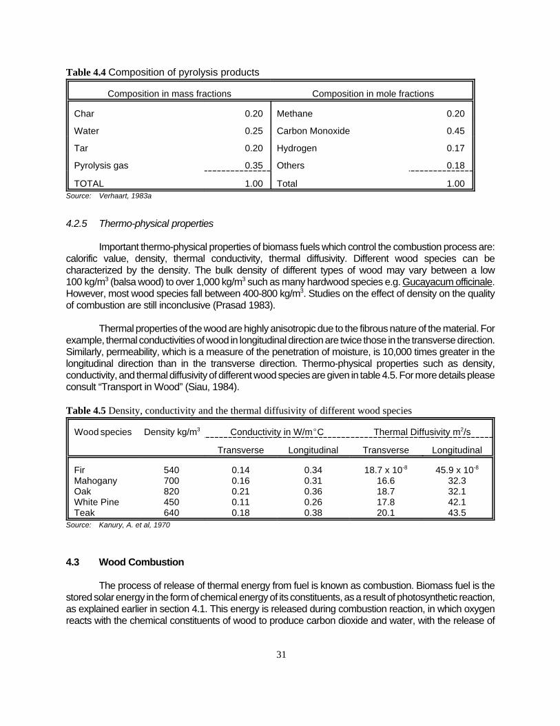
31
Composition in mass fractions Composition in mole fractions
Char 0.20 Methane 0.20
Water 0.25 Carbon Monoxide 0.45
Tar 0.20 Hydrogen 0.17
Pyrolysis gas 0.35 Others 0.18
TOTAL 1.00 Total 1.00Source: Verhaart, 1983a
Table 4.4 Composition of pyrolysis products
Wood species Density kg/m3 Conductivity in W/mEC Thermal Diffusivity m2/s
Transverse Longitudinal Transverse Longitudinal
FirMahoganyOakWhite PineTeak
540700820450640
0.140.160.210.110.18
0.340.310.360.260.38
18.7 x 10⁻⁸
16.618.717.820.1
45.9 x 10⁻⁸
32.332.142.143.5
Source: Kanury, A. et al, 1970
Table 4.5 Density, conductivity and the thermal diffusivity of different wood species
4.2.5 Thermo-physical properties
Important thermo-physical properties of biomass fuels which control the combustion process are:calorific value, density, thermal conductivity, thermal diffusivity. Different wood species can becharacterized by the density. The bulk density of different types of wood may vary between a low100 kg/m3 (balsa wood) to over 1,000 kg/m3 such as many hardwood species e.g. Gucayacum officinale.However, most wood species fall between 400-800 kg/m3. Studies on the effect of density on the qualityof combustion are still inconclusive (Prasad 1983).
Thermal properties of the wood are highly anisotropic due to the fibrous nature of the material. Forexample, thermal conductivities of wood in longitudinal direction are twice those in the transverse direction.Similarly, permeability, which is a measure of the penetration of moisture, is 10,000 times greater in thelongitudinal direction than in the transverse direction. Thermo-physical properties such as density,conductivity, and thermal diffusivity of different wood species are given in table 4.5. For more details pleaseconsult “Transport in Wood” (Siau, 1984).
4.3 Wood Combustion
The process of release of thermal energy from fuel is known as combustion. Biomass fuel is thestored solar energy in the form of chemical energy of its constituents, as a result of photosynthetic reaction,as explained earlier in section 4.1. This energy is released during combustion reaction, in which oxygenreacts with the chemical constituents of wood to produce carbon dioxide and water, with the release of

32
CO % H2O
Solar Energy)))))))))><)))))))))
Thermal Energy
CH2O % O2 (4.6)
Figure 4.3 The fire triangle
Figure4.4 Processes and temperatures in aburning piece of wood (Hasan Khan and Verhaart1992)
heat
fuel air
Heattransfer
masstransfer
heat. Photosynthetic and combustion reactions are reversible reactions,which can be depicted by thefollowing simplified equation:
The physico-chemical processes involved inthe storage of chemical energy in the fuel and thesubsequent conversion of this energy into heat arecomplex in nature. Any combustion process can bedepicted by the fire triangle shown in figure 4.3. Thefigure shows that for self-sustained combustion,three components are essential, namely: fuel, air andheat. Combustion is a complex process in whichprocesses of devolatilization, cracking andcombustion take place almost simultaneously. Theamount of energy released during combustionreaction depends on the temperature, pressure, theproducts of reaction and the state of water produced.These last two factors are important becauseincomplete combustion will result in the production ofcarbon monoxide and other combustible materials,which results in the loss of potential energy of fuel.Liquid or vapour state of water, produced duringcombustion of hydrogen in the fuel, will effect the netheat released. This complex process is depicted infigure 4.4 and takes place in three stages, asexplained in the following sections.
4.3.1 Stage 1 combustion
Easily combustible kindling (such as treeleaves, wood shavings, scrap paper and kerosene)on burning, raises the temperature of the spot onwhich the radiation from the flame is incident. Thisheat gets distributed throughout the material due toconductive heat transfer, thus raising thetemperature of the material. When the temperaturerises to 100EC, drying of wood takes place due toloss of absorbed and weakly bound water. Thisprocess continues into the deep interior; a part of theheat of combustion is utilized in this endothermicprocess (heat consuming). Hence, the higher themoisture content of the wood, the greater is the lossof energy.

33
4.3.2 Stage 2 combustion
As the temperature is raised further, the pyrolytic decomposition of the wood starts. At atemperature of about 150EC, the release of volatile matter begins along with the appearance of semi-liquidtar. In case this stage gets prolonged due to quenching of the flame, the fuel starts smouldering and darkor grey/blue smoke with a strong smell is given off. This results in the loss of some useful energy of wood.The tar gets deposited in the tunnels and chimney resulting in their choking as mentioned earlier in section4.2.1. There is also the danger of fire in the chimney due to the spontaneous combustion of the depositedtar. Tar also gets deposited on the cold surface of the pots resulting in their blackening.
4.3.3 Stage 3 combustion
Volatile matter, being at a higher temperature, rises due to the buoyancy force. During the rise,it mixes with the surrounding air. This mixture of volatile matter may reach the combustible limit and getignited, if sufficient heat is available. The flame resulting from combustion may persist if the heat releasedfrom the flame is sufficient for sustained release of more volatiles from the burning surface. Otherwise, itwill flash back to the surface. Self-sustained combustion commences at around 225EC and reaches apeak at about 300EC. During this stage, heat released by the combustion process is more than thecombined losses and hence there is a net positive release of heat.
Thus, it can be concluded from the above discussion that for the evaluation of the combustionprocess, the understanding of the pyrolysis process and the subsequent burning of the released volatilematter and char is necessary. The second stage determines the extent and nature of volatiles and the chargenerated while the third stage determines the extent to which the potential heat in the volatile matter andchar is released. The pyrolytic process as explained earlier (section 4.2.4) suggests that, for the bestdesign of the stove, the following factors (which govern the rate of pyrolysis) must be taken into fullconsideration: the temperature, rate of heating, residence time of biomass in the combustion chamber andphysical characteristics of the fuel such as size and shape. Furthermore, an understanding of the heatlevel required for ignition as well as for the maintenance of combustion and their dependence on thethermo-physical properties such as density, specific heat, thermal conductivity, calorific value and moisturecontent is essential.
4.3.4 Combustion of the products of pyrolysis
Combustion of the products of pyrolysis of biomass, in particular, char and volatiles, takes placein two modes, flaming combustion of the volatiles and glowing combustion of the char. The completeprocess is shown in figure 4.5.
a) Combustion of volatiles
The composition of the volatiles is variable and depends on the temperature of pyrolysis and thelength of time that these volatiles are subjected to an elevated temperature. Thus, the combustion ofvolatiles is a complex process. The higher the temperature of the pyrolytic zone, the more severe is thecracking of the higher molecules into smaller ones, which in turn burn more readily. Wood fires generallyproduce a diffusion flame. This consists of a jet of flammable gas with a combustion reaction taking placeat the air-gas interface, resulting in the formation of hot gaseous combustion products and heating theremainder of the gas to some extent. The products of combustion are lighter due to their high temperatureresulting in a vertical rise-up. During the ascent, these products also entrain some surrounding air.

34
Figure 4.5 Wood combustion
FUEL
AIR
HEAT
VOLATILEMATTER
FLAMINGCOMBUSTION
FLUEGAS
FLUEGAS
GLOWING COMBUSTION
AIR
FIXED CARBON (CHAR)
HEAT
LIGHT
INFRAREDRADIATION
CONDUCTION
CONVECTION
RADIATION
AIR
Another process, which takes place simultaneously is the diffusion of air into a jet of gas throughthe difference in the partial pressure of the constituents. Diffusion of air into unburnt volatile material at hightemperature results in the combustion of volatile material. Soot and unburnt chemical compounds areformed if the temperature of the combustion zone is not sufficient. Temperature can fall below ignitiontemperature due to the quenching effect of the entrained air or the contact of the flame with a cold surface.If the residence time of the flammable gas at a higher temperature is long, then hydrocarbons ofprogressively higher carbon contents are formed due to partial oxidation.
b) Glowing combustion
Char, which is a solid carbon residue left after the release of volatile matter, burns with a glowingflame. When the combustion takes place at the surface, carbon dioxide is formed with the liberation ofheat. However, if the combustion reaction takes place in the bed or char at high temperature, then carbon

35
1 C (graphitic) + O2 (gas) 6 CO2 (gas) + 178,430 kJ2 C (graphitic) + CO2 (gas) 6 2CO (gas) - 78,210 kJ3 2C (graphitic) + O2 (gas) 6 2CO (gas) + 100,230 kJ4 2CO (gas) + O2 (gas) 6 2CO2 (gas) + 256,640 kJ5 2H2 (gas) + O2 (gas) 6 2H2O (gas) + 219,300 kJ6 C (graphitic) + H2O (gas) 6 CO (gas) + H2 (gas) - 59,540 kJ7 C (graphitic) + 2H2O (gas) 6 CO2 (gas) + 2H2 (gas) - 40,870 kJ8 CO (gas) + H2O (gas) 6 CO2 (gas) + H2 (gas) + 18,670 kJ
B 'Bo
1 % [m]& [m] × (Cp × )T % L) (4.7)
dioxide is reduced to carbon monoxide. This must be burnt with secondary air to produce carbon dioxideand heat. Otherwise,it will result in the loss of potential heat as well as cause pollution.
4.3.5 Combustion reactions
During the combustion process a number of chemical reactions take place. These reactions donot simply involve the addition of oxygen to carbon and hydrogen, in the fuel, to produce heat. There isa combination of a number of primary, as well as secondary reactions in which the products of the primaryreactions also take part. The principal reactions can be summarized as shown in the following box. A plussign indicates an exothermic reaction (evolution of heat) while a minus sign indicates an endothermicreaction (heat absorbed). The heat of reaction corresponds to a base temperature of 25EC at constantpressure and in the state as indicated. The extent of completion of these reactions is dependent on anumber of factors, namely: equilibria, specific reaction rate, and contact catalysis. Reaction 2 (see box)predominates at temperatures below 600EC, while Reaction 1 predominates at temperatures above800EC. Performance of a combustion system on the whole, depends on the physico-chemical andthermochemical properties of the fuel.
4.3.6 Effect of moisture on combustion of wood
Combustion characteristics of wood are influenced by the presence of moisture in it. The moisturecontent is defined as the mass fraction of water, on a dry wood basis (section 4.2.1). The effect of moistureon the heat value of wood is given by:
where [m] is the moisture content, L is the latent heat of evaporation, B the heat of combustion of woodas fired, and Bo the lower heat of combustion of oven dried wood.
Studies conducted by Era and Saima (1976) showed that the stove efficiency is greatly dependenton the moisture content of the wood. It has been found that the minimum intensity as well as energyrequired for ignition increase with the increase in its moisture content. An upper limit of moisture is reachedwhen it becomes too difficult to maintain combustion, even in the presence of substantial heat input. Thisis because the net heating value is less than the heat required for combustion. This limiting value isreached at moisture content of about 67% (dry basis) or so. At this level of moisture, the calorific value getsreduced to about 5,000 kJ/kg from 18,500 kJ/kg for wood with about 10% moisture content.

36
penetration rate 'power output × volume/surface ratio
volatile fraction × total fuel used × net cal. val. (4.8)
Controlled experiments undertaken for estimation of the effect of moisture on combustion showthat there is a fall in the efficiency with increase in moisture in the wood. However, the highest efficiencyis achieved at a moisture content of about 5%. This can be attributed to the sudden/too fast release of heatin the case of bone dry wood.
The time taken by the fire to reach the peak value in the initial stage of fire and the thickness ofthe fuel bed depends on the moisture content of the wood. Once the peak power is reached, the fuel bedis hot enough to evaporate moisture without any problem. However, the peaking period also depends onthe fire lighting and tending method. The maximum power of volatiles PV,max is also dependent on themoisture content of the wood and has been found to decrease with increase in moisture and becomesconstant at a power density of 14 watts/sq.cm.
4.4 Combustion Controlling Factors
Important factors which influence combustion are:
! Physical and chemical properties of the fuel; ! Fuel/air ratio; ! Temperature of the flame/envelope; ! Mode of fuel supply; ! Primary and secondary air supplies.
4.4.1 Physical and chemical properties
As stated earlier, the combustion process in a cookstove is greatly influenced by the relativeproportion of macroscopic constituents of the biomass, namely: cellulose, hemicellulose and lignin. Therelative proportion of these constituents varies in different species of biomass. A cookstove designed toburn fuels rich in cellulose will require a better control of secondary air due to production of more volatiles.On the other hand, primary air considerations become more important in a fuel containing more lignin. Seesections 4.1 and 4.2 for more details of physical and chemical properties.
4.4.2 Size and shape of the fuel
Volume to surface ratio of the wood fuel is dependent on its size. This ratio has an importantbearing on the combustion characteristics of the wood and other woody biomass. Fire penetration rate,which is the rate at which the char boundary advances into the virgin wood is a function of volume/surfaceratio (v/a),as is given by equation:
where, power output in kW, volume/surface ratio in mm, total fuel used in kg, net calorific value in kJ/kg.Power output of a fire is given by equation:

37
power output 'sum of individual charges × net calorific value
total duration of experiment (4.9)
na.st '1
0.21(1 &
1
2× f ) ×
[c]
12&
y
32[mol] (4.10)
With the increase in volume /surface ratio, CO/CO2 ratio also increases due to increase in the release ofvolatiles, which remain unburnt as a result of insufficient availability of air.
4.4.3 Primary and secondary air supplies
The introduction of the right amount of air alone is not enough. It is important to introduce it at theright point and time. The air supplied from below the grate in which it reacts with the solid biomass/charis known as primary air. While the air which is introduced from above the grate and which reacts with thevolatile matter is known as secondary air. The relative amounts of primary and secondary air will dependon the proportion of fixed carbon and volatile matter in the biomass fuel, respectively. This will decide thearea of the openings for induction of primary and secondary air. Primary air is supplied through the holesin the grate or the side opening. It has been found that it is not possible to get a power output of more than4 kW in a shielded fire when side holes are used for the air inlet.
4.4.4 Fuel/air ratio
A fuel can burn only in the presence of air, which supplies the oxygen required for combustion. Aproper air to fuel ratio is essential for efficient combustion of fuel. Both rich (deficient in air) and lean(deficient in fuel) fuel/air mixtures will result in incomplete combustion. Wood contains nearly 43-44%oxygen and hence a major part of the oxygen required for combustion is supplied by the wood fuel itselfwhile the rest is to be provided from the air. This is in contrast to other solid fuels like coal where a largeamount of oxygen from the air is required.
Due to the heterogeneous nature of the solid biomass combustion process, only a part of the airentering a combustion chamber is utilized in the chemical process of combustion, while the rest of the airsimply passes through the cookstove. Thus, it becomes necessary to admit more air, than theoreticallyrequired. An excess air factor of 1.5 to 2.0 is generally recommended for good combustion. In other words,one kg of wood needs 1.4 kg of oxygen at NTP or 6.5kg of air. Applying the excess air factor of 2, thenthe total quantity of air needed becomes 13 kg. To raise this amount of air to the average flue gastemperature of 450EC would require heat of 5.85 MJ. The excess air factor can be determined also fromthe percentage of carbon dioxide in the flue gases, which can be measured with the help of an Orsatapparatus. Carbon dioxide content increases with a decrease in the excess air factor and vice versa.
In actual practice, even when the theoretical minimum amount of air, or a little more, is suppliedfor combustion, the carbon may not get fully oxidized to carbon dioxide. In such situations, the fraction ofcarbon converted to carbon dioxide as well as carbon monoxide is estimated and used for calculating theamount of air required for combustion from ultimate analysis of the wood. This can be calculated by thefollowing correlation (Prasad et al, 1983):

38
TFT 'sensible heat in fuel and air % heat of combustion
total quantities of combustion products × mean specific heat (4.11)
where, Va.st is the stochiometric amount of air required for combustion, p is the % of carbon in the wood,f is the fraction of wood that is converted into CO, y is the percentage of oxygen minus eight times thepercentage of hydrogen.
The design of the air inlet in the fire box is based on this value. Experiments show that there is asharp increase in the CO formation if the excess air factor falls below 2. However, the excess air factorrequired for complete combustion of fixed carbon and volatiles is not necessarily the same. Jusu (1987)proposed that no excess air is required to burn charcoal on the fuel bed. In that case, even if excess airis supplied to the fuel bed, it will act as secondary air and the combustion of charcoal will not benefit. Therate at which primary and secondary air must be supplied depends on the heat requirement during cookingand the way the fire is tended.
4.4.5 Temperature of the flame
Combustion can be hindered if the flame comes in contact with a cold surface, due to thequenching effect. The temperature of the gases near the cold surface decreases below the ignitiontemperature, due to loss of heat to the cold surface, irrespective of the presence of hot gases nearby.Thickness over which no flame exists, known as quenching distance, is a function of temperature of thesurrounding/enclosure and decreases with the temperature. Incomplete combustion is responsible for sootdeposition on the cold surface or the smoke in the flue gas. Thermal stratification due to quenching canbe reduced by generating artificial turbulence, to ensure the mixing of gas and air and increase residencetime. This can be easily done by introducing design innovations.
From the thermodynamic and heat transfer perspective, the flame temperature should be as highas possible. This depends on the calorific value and the excess air factor. One of the major reasons forthe popularity of open-fire cooking is rapid cooking of food as the pot is surrounded by the flame, thetemperature of which exceeds 800EC. The thermodynamic efficiency of the combustion process is givenby the ratio (T2-T1)/T1, where T2 is the highest temperature attained by the flame and T1 is the outlettemperature of the gas. Thermal efficiency is more dependent on the flame temperature than the flue gasoutlet temperature as the latter varies within a small range. Actual temperature is difficult to measure asthere is a variation in local temperature at different points in the flame, since air/fuel mixing as well ascombustion processes are not instantaneous. Hence, a theoretical flame temperature is generally usedin the combustion calculations. The theoretical flame temperature (TFT) is given by the equation:
This shows that the theoretical flame temperature is not only a function of the calorific value ofwood but also of the excess air factor. Under perfect combustion conditions and the use of a theoreticalquantity of air for combustion, the flue gas should contain only carbon dioxide, water vapours and nitrogen.However, under actual conditions, the products of combustion contain unburnt materials such as carbonmonoxide, hydrogen and solid and liquid materials which form smoke. In addition, considerable heat lossestake place in the combustion chamber. Because of this the actual flame temperature is usually 30-170EClower than the theoretical flame temperature.
4.4.6 Fuel supply
Combustion is also influenced by the mode of fuel supply. Fuel can be supplied in three modes,namely: continuous, stored and batch. In cookstoves using solid fuel, it is generally supplied in batch mode

39
in which fuel is supplied in charges of small quantities. A number of charges are, therefore, needed in onecooking job. The power output of the fire cycles between minimum and maximum from the instant ofcharging to the time when generation of volatiles is at a maximum. A lot of heat is absorbed by the freshcharge which is responsible for low power output. Thus, it can be concluded that the smaller the chargeof the fuel, the more unsteady is the behaviour of the fire. The storage mode of fuel charging requiressufficient care so that the bulk of the fuel does not come in contact with the high temperature, which willresult in uncontrollable spontaneous combustion.
4.4.7 Concluding remarks
A number of attempts have been made by different researchers to define a universal criterion forself sustained combustion. It has been concluded that ignition is related to the temperature at any pointinside the material attaining a certain value. The temperature distribution for different boundary conditionshas been reported by Carlsaw and Jaeger (1959). Steward (1974) derived a correlation, based on theminimum incident energy for ignition depending on the Newtonian cooling coefficient, based on theexperimental results of Simms and Law (1967). A variation of +15% to -50% between the theoretical andexperimental results was found. This may be due to lack of understanding of ignition in the gas phase andthe interference of other parameters such as fuel thickness, configuration of fuel in the bed and bedvoidage.

40
5 IMPROVED COOKSTOVE TECHNOLOGIES
5.1 Combustion in Small Enclosures
The developmental approach to cookstove design, as explained in section 1.2 and sections2.2-2.3, has been shifting from fuel efficient stoves to emission efficient stoves. A high performancestove should be efficient from both these perspectives, so as to ensure conservation of the fuel aswell as the environment. This will not only reduce the drudgery of the users but will also save themfrom the harmful effects of the pollutants emitted during combustion. One of the strategies adoptedin a large number of designs is to improve thermal efficiency and provide a chimney for the removalof smoke. Although this strategy helps in improving the indoor air quality, the quality of combustionis questionable in a number of designs. A better approach would be to increase the heat transferas well as the combustion efficiency. An increase in the heat transfer results from the efficienttransfer of heat produced during combustion and a reduction in the losses from the body of thestove. Combustion efficiency can be enhanced by ensuring complete combustion. A completeconversion of chemical energy to heat with a minimum (but sufficient) amount of excess air cantake place if the following conditions are met:
! High temperature in the reaction zone; ! A requisite supply of the oxidant (air) and its complete mixing with the fuel; ! Adequate residence time of the reactants (air and fuel) under the above conditions in the
reaction zone.
In case any of these conditions is not met, the combustion reaction will not proceed tocompletion, resulting in the emission of pollutants and the loss of potential heat. In contrast to liquidor gas fuel burners, it is extremely difficult to meet these conditions in heterogeneous combustion,as is the case in cookstoves using solid biomass fuel. Whenever there are reducing conditions dueto a deficiency of air or an excess amount of volatile matter in the combustion zone, free carbonand hydrocarbon compounds escape from the combustion zone without complete combustion,resulting in the formation of soot and other toxic poly-aromatic hydrocarbons. Thus the design andoperating parameters are as important as the fuel parameters. As shown in section 4.1, there isvery little variation in the chemical composition and energy density (energy/unit mass or volume)in woody biomass. However, there is a significant variation of other properties among differenttypes of fuels: wood, agriculture residues, dung cakes, etc. This variation in the properties has aprofound effect on the overall efficiency and hence must be taken into consideration in the designof cookstoves. In addition to these, there are a number of process factors, which must be takeninto consideration as well, so as to maximize efficiency and minimize emissions. These can bedivided in to three distinct categories, namely: design, fuel and operational factors:
Fuel factors: Physical and chemical properties of fuel such as volatile matter, moisture,ash, etc.
Operational factors: Burn rate/size of the fuel ratio, volume to surface ratio, mode of fuel supply,cooking time, etc.
Stove factors: Fuel/air ratio, temperature of flame and/or envelope, mode of fuel supply,primary and secondary air, mass of the stove, etc.

41
FactorsAction taken to
Minimizeemissions
Maximizeefficiency
Fuel factors- Ash contents - Volatile contents - Moisture contents
MinimizeMinimize
Optimize @ 25%
MinimizeMinimize
Optimize @ 10%
Operational factors- Burn rate - Size of fuel charge - Ratio of charge size to burn rate - Volume to surface ratio
MaximizeMinimizeMinimizeMaximize
MinimizeMinimizeMinimizeMaximize
Stove factors- Combustion confinement- Temperature - Excess air - Preheated primary air (down draft stove) - Mass, short cooking time - Mass, long cooking time - Time during burn - Altitude
MinimizeMaximizeOptimizeMaximizeMinimizeMaximizeHigh early
-
MaximizeMinimizeOptimizeMaximizeMinimizeMaximizeLow early
-Source: Smith, 1987
Table 5.1 Qualitative effect of different factors on thermal and combustion efficiency
Due to inconsistencies in the measurement techniques and the small data base, it is difficultto predict quantitatively the effect of these variables on the overall efficiency. However, the qualitativeeffects of some of these factors on combustion and thermal efficiency are given in table 5.1
A critical examination of the factors given in table 5.1 shows that the fuel parameters areuncontrollable as they depend on the type of fuel. On the other hand, operational parameters suchas fuel size and fuel feeding are user specific, while the stove parameters are design specific. Itcan be further observed that on a qualitative basis, the stove factors and some of the operationalfactors are competing factors. However, the data base is inadequate for a quantitative evaluationof the effect of these parameters on the combustion and heat transfer efficiency. At times,contradictory conclusions have been drawn by different authors. This is partly due to a lack ofproper understanding of various process principles during which the combustion takes place insmall enclosures, and partly due to the inadequacy of the experimental procedures used.
It has been estimated (Sangen 1983) that the overall efficiency, during combustion at aparticular value of the burning rate, depends on the characteristics of the enclosure (semi enclosedcombustion chamber, enclosure without chimney, enclosure with chimney, etc.). With an increasein the burning rate, the heat transfer efficiency decreases, while the combustion efficiencyincreases. The nature of the combustion operation such as steady/ unsteady combustion, shortterm/intermittent operation, which is controlled by the ratio of the burn size and the burn rate, hasa profound influence on the overall efficiency of the cookstove.

42
Pdes ' 0.7 × (Pc % Pv.max) (5.1)
A × H ½ (5.2)
Burning of wood in small enclosures can be classified as controlled combustion in contrastto free burning of wood in an open fire. However, the operation of the cookstove is dynamic in naturebecause of the interdependence between the rate of combustion, rate of induction of air and the draft.The rate of combustion is strongly dependent on the manner in which the combustion air is supplied.In the case of small enclosures, the combustion takes place due to the pressure field set up as aresult of the upward movement of combustion products and entrainment of air through the fire-boxopening and the grate, if provided. On the other hand, combustion in open-fire is maintained throughthe laminar or turbulent entrainment of outside air, depending on the size of fire. Hence, apart fromcombustion, fluid flow considerations are equally important in the design of an ICS.
5.1.1 Design considerations
The rate of heat output from a fire in an enclosure is assumed to be composed of twocomponents: heat released from charcoal and heat released from the combustion of volatile matter.This assumption is valid for the entire combustion process, in low power fires and during the steadystate period at modest power levels as well. However, for large power levels, this assumption willnot be valid as the fuel bed will consist of wood under various stages of thermal decomposition.Even in low and medium fires, it is difficult to estimate the rate of burning of charcoal or volatilesindependently. Based on various assumptions the design power has been defined (Bussman et al1983) as:
where pv.max is proportional to: the fire penetration rate, volatile fraction, charge weight, heat ofcombustion of volatiles, and the area to volume ratio of the wood pieces.
The rate of heat output is controlled by the volumetric flux of air and depends upon the sizeof the opening of the fire-box and grate hole openings. The burning characteristics of fire in smallenclosures can approach the combustion in an open-fire if the size of the fire-box opening and thegrate opening is increased substantially. Thus, the amount of heat released from a cookstove canbe controlled by controlling the size of the fire-box and the grate openings and/or using otherstrategies such as the provision of dampers or building up of a resistance in the flow path.
Unfortunately, very little information is found in the literature with regard to experimentaldata on the combustion behaviour of wood in ventilated controlled fires as encountered in an ICS.However, extensive studies have been conducted in order to be able to estimate the fire load inrelation to the fire resistance in buildings. The only difference in the configuration of these studiesand that of cookstoves is that the side opening serves both as outlet and inlet for the combustionproducts in buildings, while these are discharged from the top or a separate side outlet in the caseof cookstoves. On the basis of these studies, combustion in small enclosures can be characterizedby an opening factor defined as:
where A is the area of the side opening and H its height.
For a small opening factor (small air flow), the mean burning rate during flaming combustionfor a certain range of fire load densities (weight of fuel per unit area) is almost proportional to the

43
Pav 'E)mf × Hc
tT(5.3)
air flow rate but independent of fire load density. However, with a large opening factor (large air flow)the burning rate approaches a constant value. Under these conditions, the system tends to approachthe limiting conditions of the open-fire, where the burning rate increases in proportion to the fireload/surface area.
It has been estimated that for ventilation controlled fires, a minimum of 15 grams of fuel percm2 of area opening is required. The proportional regime lasts till the measured flow is about 10litres per second. These conditions should be satisfied in the design of ICSs, as the combustionof wood in an ICS falls in the category of the proportional regime. The combustion has a tendencyto become turbulent between 260EC and 290EC (Micuta 1981) if the air supply is not restricted. Butthis can be done by reducing the air supply or the draft or both.
It can be concluded that combustion in small enclosures, as applicable to solid biomassburning cookstoves, is not properly understood. There is a need to undertake extensive controlledexperimental work on the quantitative estimation of the effect of various parameters such as fuel,stove, and operational parameters on the combustion as well as heat transfer efficiency.
5.2 Influence of Sub-system Design on Optimum Efficiency
The design of an ICS involves the application of heat transfer, combustion and fluid flowprinciples in order to attain complete combustion of the fuel with a minimum amount of excess air,maximum transfer of heat from the flame and the flue gases to the cooking vessel, and a minimumloss of heat to the surroundings. This can be accomplished by optimizing and/or incorporatingvarious subsystems in the stove, as shown in figure 5.1. These subsystems are:
! firebox/combustion chamber and stove walls; ! grate; ! air/fuel inlet; ! flue/chimney; ! baffles; ! dampers; ! connecting tunnels.
5.2.1 Fire-box/combustion chamber
This is the chamber in which the combustion of the fuel takes place. It has provisions forentry of fuel and air required for the combustion process. Different configurations for entry of fueland air are discussed in later sections. The chemical energy of the fuel is released in this chamberin the form of heat. The engineering design of the fire-box is very important in order to ensurecomplete combustion and the efficient delivery of this heat to the cooking pot. The design of thefire box is based on the average power output Pav of the cookstove in kW, which is defined as:

44
Figure 5.1 Isometric view of Dhaula Dhar chullah
Brav ' Pav × H&1c (5.4)
Brav 'V
Vth(5.5)
where E)mf equals the sum of the individual wood charges during the experiment, Hc is the netcalorific value of the fuel and tT is the total burning time. Equation 5.3 can also be written as shownin equation 5.4 where Brav equals the average burning rate:
Through substitution, equation 5.4 can also be written as follows:
where V is the volumetric flow rate of primary air and Vth is the theoretical amount of air requiredfor combustion.
The design of the combustion chamber must take into account the effect of some of thecompeting factors such as heat transfer and combustion quality. Efforts to maximize the heat

45
Hcc ')Mf
x × pf × Acc(5.6)
Acc 'Pdesign [kg]
Pdensity [kg/m2]
(5.7)
Hfl ' C2 × P 2/5 (5.8)
transfer deteriorates the quality of combustion and vice versa (see table 5.1). On the basis ofstudies conducted on open fires (Bussman 1988) and pyrolysis considerations, the combustionchamber can be assumed to be composed of two sections, namely: the charcoal combustionsection and the volatiles combustion section.
The volume of the charcoal section depends on the power output required, the mass ofwood charged, the packing density and the burning characteristics of the wood or other woodybiomass under consideration. It can be calculated by using equation (5.6):
where )Mf denotes the fuel charged (kg), x is the packing density, pf is the density of the fuel, Acc
is the cross-sectional area of charcoal bed and Hcc equals the height of the charcoal bed.
In the case of an ICS with a grate, the power density depends on the type of grate. Thediameter, calculated by the use of equation (5.7) gives a smaller diameter of the fire-box in relationto that of the pan, which results in a lower efficiency. From his studies on open fires, Prasad(1981b) concluded that the heat output from the combustion system increased with the increaseof the fuel bed diameter and its thickness. However, a large fuel bed thickness hampers theefficient combustion. The diameter of the user's pot and the quantity of the food cooked should alsobe taken into consideration in deciding the fuel bed diameter. The radiation input to the panincreases with:
! the decrease in fuel bed diameter to pot diameter ratio for a given height of pot above thefuel bed;
! a reduction in the pot height above the fuel bed for a given fuel bed diameter to potdiameter ratio.
In designing the charcoal section, the contribution of the convective heat transfer shouldalso be taken into consideration. A detailed analysis of the heat transfer characteristics of the open-and shielded-fires as applicable to cookstoves is presented by Bussman (1988) and Prasad(1981b). In the design of the volatile combustion section, the height of the flame is taken intoconsideration. If the height of this section is less than the height of the flame, the flame will touchthe cold pot which will result in it being quenched. This leads to incomplete combustion resultingin tar deposits and an increase in the emission of pollutants.
Based on the experimental studies on flame heights in open fires, Herwijn (1984) concludedthat the flame height of an open-fire can be expressed by:

46
tb ' 550 × M0.38f (5.9)
0 × Pmax × tb ' Mf × Cp × (Tb & Ti) (5.10)
where P is the power output and C2 is a constant, which depends on the type of grate. Values ofthis constant are: 75 mm/kW0.4 for a fire with a grate and 110 mm/kW0.4 for fires without a grate,for the test using oven dry white fir (wood). The use of this correlation results in higher heights ofthe volatile combustion section. A number of studies have been conducted to evaluate the effectof the height of the pan on the efficiency of the stove by Vermeer and Sielcken (1983), Sulilatu etal (1984), and Bussman (1988). The results from these studies are contradictory and inconclusive.A combustion chamber height of 150-180 mm has been suggested by Joseph (1979) for stoveswithout a grate. The combustion chamber height is a critical parameter and has a profoundinfluence on the efficiency. A low combustion chamber height will result in incomplete combustionresulting in the production of smoke due to the condensation of the volatiles. On the other hand,too high a combustion chamber results in a greater entrainment of air, resulting in the quenchingof the flame, thus reducing the radiation and convective input to the cooking vessel.
In order to decrease the radiation losses from the flame envelope and increase the heattransfer area between stove and the vessel, the combustion chamber shield is extended so thatthe vessel can be sunk in the combustion chamber. This configuration can help in reducing theradiation losses, increasing heat transfer area, and convective heat transfer. However, it puts a limiton the size and the shape of the vessel. Soot also gets deposited on the sides of the vessel.
An important factor which must be taken into consideration while designing the fire box isthat a stove design, based purely on heat transfer considerations, may not perform the cooking ata rate preferred by the user, as both are competing factors. It is advisable to sacrifice someefficiency at the expense of the user's convenience. Otherwise, the acceptability of the ICS will bedrastically reduced (Sharma et al 1992).
The design power should be based on the time required for cooking. Data on the timerequired for different cooking operations on a cookstove, as a function of quantity of food atmaximum power, is not available in the literature. In the absence of this data, correlations basedon testing of gas cooking range (GIVEG 1968) is used for the design. These can be expressed as:
where tb is the time for cooking and Mf the mass of the food to be cooked. Based on this, themaximum power can be defined as:
where 0 is the efficiency, Pmax the maximum power, Cp the specific heat of food, Tb the temperatureof boiling and Ti the initial temperature.
The application of the results obtained from open-fires based on naturally aspirated fires, asencountered in chimneyless stoves may be valid. However, the use of these in ventilated fires, i.e inthe stoves with a chimney, require close scrutiny. Geometric characteristics of the flame get modifieddue to the net positive suction effect of the chimney. Even in metal stoves with a top plate and withouta chimney, the flame characteristics get modified. Data on these aspects is lacking in the literature.
Another important aspect of the fire box design is the reduction of heat losses from the sidewall(s), as the temperature in the fire box is very high. Reduction of the heat loss through the stovewall requires the detailed analysis of the conduction process which has been presented in section

47
V ' 29.7 × A × h 1/2 × (1 & Ta/Ti)1/2 (5.11)
3.5.2. Lightweight walls will heat up much faster than thick walls. Walls made out of conductingmaterial like metal will also heat up faster. However the heat loss from the combustion chamberdepends on the rate of increase in the temperature of the wall and the amount of heat stored in thewall, which eventually gets lost to the outside. Thus, a wall made of a low thermal conductivitymaterial will result in a lower thermal loss from its outer surface. It is also desirable to make stovewalls of high specific heat material, like clay and concrete, as thin as possible. While designing acookstove there is a need to make a compromise between reduced losses and the ability of thestove to withstand the load of the cooking pot and food inside it. A lightweight metal stove withoutouter insulation will attain a high outer surface temperature, which will result in higher surfacelosses and may cause burn injuries. The use of insulating material or a double wall constructioncan substantially reduce the surface losses from the fire-box.
A cylindrical fire-box of uniform diameter can accommodate cooking vessels with a diameterequal to or greater than the fire-box diameter. In order to accommodate vessels of diameter lessthan the diameter of the fire-box, either a reducer ring is used or steps of progressively smallerdiameter are provided in the firebox itself, so as to accommodate pots of different diameters.
A side opening in the stove serves the purpose of air and fuel inlet. In stoves without a grate,the burning rate, and hence the temperature, is controlled by this side opening. Often this openingis also used for baking of traditional items e.g. local breads, peppers, etc. Apart from serving theseuseful functions, it causes considerable radiation and convective losses. Thus, a side opening hasa profound influence on the efficiency of the cookstove. The side opening for air is calculated on thebasis of the volumetric flow rate of the air using the following correlation (TERI 1982):
where Ta and Ti are the temperatures of ambient air and the average temperature of the bed, A isthe area of the side air entrance, and h is the height of the air entrance.
In the case of a stove with a grate, the smaller of the two areas (that of grate or the sideopening) is used in the above equation. As the side opening is also used for fuel feeding, its designshould take into account the resistance offered by the fuel to the flow of air.
A number of configurations have been used by different designers for the supply of primaryand secondary air. Functions of primary and secondary air have already been explained in section4.4.3. In the cookstoves with a grate but without a side opening, the primary air is supplied frombelow the grate and separate openings are provided above the fuel bed for the secondary air. Insome cases, vessel mounts act as an opening for the secondary air. When side openings areprovided along with a grate, the air enters from the side opening(s) as well as through the grate.The relative proportion of the flow of air depends on the extent of resistance encountered throughthese openings. In cookstoves with side openings without a grate, both primary as well assecondary air enters through the side opening(s).
Cookstoves with a cylindrical fire-box and a side opening are mainly used when cooking isdone with long logs of wood or with long-stemmed agricultural residues, such as cotton sticks andcoconut fronds. When loose biomass is used, the feeding is done either from the top or through aslanting grate. However, in some designs of the ICS, the feeding of wood in small pieces or charcoalis done from the top. In these stoves, the cooking vessel has to be removed before each feeding.

48
5.2.2 Grate
The use of a grate in a cookstove improves the combustion efficiency due to a more uniformdistribution of air in the fuel bed as a result of better mixing of air with the volatile matter. Thisresults in an increased rate of combustion with a steady flame, thus reducing the losses from thesides of the chamber as the flame does not touch the sides. Air also gets preheated during itspassage through the hot fuel bed. Apart from these advantages, the grate reduces the conductionlosses from the fuel bed as well as charcoal formation. The formation of carbon monoxide as wellas the loss of unburnt volatile matter is reduced at the same time. It facilitates the removal of ash,while retaining the charcoal. The choice of a correct grid spacing of the grate is very important. Ithas been suggested that the free space should be approximately 25-30%. However, in a properlydesigned cookstove, it should be based on the air requirement for the design power.
The volumetric flux of air required to generate a specified power is a function of Av×h1/2, asstated in equation 5.11 above. The volumetric flux will be controlled by the lesser of the two areas,namely the area of side entrance and that of the grate. If the area of grate opening is larger thanthe side opening, it becomes inert. On the other hand, if the grate opening area is less than theside vent, it controls the power rating of the stove, as the rate of aspiration is dependent on thisopening. Too small a grate opening will result in a large pressure drop across the grate.
Another useful function of the grate is that it helps in keeping the fire compact. De Lepeleire(1981) suggested a slope of 45E for the combustion chamber with a grate. However, View Factorconsiderations, as outlined under the radiation section (section 3.5.2b), must be taken intoconsideration as well for a proper design of the combustion chamber.
The grate to pot distance has a great influence on the efficiency of the stove. Changes in thisdistance bring changes in the View Factor and the surface area of the vessel. This affects the radiativeheat transfer. While the View Factor between fuel bed and the pan decreases, the View Factor betweenfuel bed and wall, and the wall and the pan increases. When the wall temperature is high, the radiationfrom the side wall is not negligible as compared to that from the fuel bed. In addition, changes in the flowresistance take place. As a result, changes take place in the gas flow and the gas temperature. Thisinfluences the convective heat transfer. Thus it can be concluded that the grate to pot distance has to beoptimized taking into consideration other geometric parameters of the stove.
Grates can be made from a large number of materials, such as cast iron, mild steel sheet,mild steel rods, mild steel strips and clay/ceramic. However, the cost, the formability, and thedurability have to be taken into consideration in the selection of material.
5.2.3 Pot hole/rim design
For the efficient operation of an ICS, especially one using a chimney, a proper design ofthe rim of the various chambers of the cookstove is very important. A rim should be designed insuch a manner that the flue gases do not escape from beneath the pot. A tapered design of therim is preferred as cooking vessels of different diameters can be accommodated without a loss offlue gases. In the channel type stove without a chimney, the hot flue gases from the combustionchamber are allowed to expand over a large tapered rim to increase the convective heat transfer.In this type of stove a proper design of the rim becomes very critical, otherwise the thermal as wellas the combustion efficiency will be considerably reduced.

49
Psnet ' Dst & Pdyn & Pres (5.12)
5.2.4 Chimney
In wood burning ICSs, sufficient air has to be provided in order to achieve completecombustion. This is accomplished by providing sufficient air openings in the fire-box of naturallyaspirating stoves. However, in multi-pot stoves, even with a large opening an additional positivesuction head is required to overcome the resistance offered by the flue passages. This isaccomplished by providing a chimney which creates suction at the top as a result of thetemperature difference between the hot gases at the base of the chimney and the ambient air. Asa result, flue gases are drawn from the stove and air is induced into the cookstove. Three forcescontrol the motion of fluid through the cookstove. These are:
! Buoyancy force created by the fire; ! Draft created by the chimney as results of the temperature difference between the base of
the chimney and the outside air and the height of the chimney; ! The opposing frictional forces.
The optimum performance of the stove depends on the interplay of these forces. Theseforces can be manipulated by modifying the design parameters. The buoyancy force can bechanged by changing the rate of burning of the fuel. The draft can be changed by extracting moreor less heat for the second pot hole, which will change the temperature of the flue gas at the baseof the chimney. The same effect can be created by changing the height of the chimney. Thefrictional forces can be manipulated by changing the design of the flue passages and the diameterof the chimney as well as through the provision of damper(s).
In an ideal situation, the buoyancy force should be equal to the draft under the first pot holeso as to create a balanced flow whereby the flame will rise up to the first pot and then move to theside tunnel. Such an ideal situation is difficult to obtain in the cookstoves due to the variability ofthe fuel quality and the combustion characteristics. Under these conditions it is recommended todesign a stove with a positive draft in spite of the fact that the stove will receive less heat than awell shielded open-fire as observed by Nievergeld (1981), Visser and Verhaart (1980).
The chimney should be designed in such a manner that it should not only be sufficient toovercome the resistance offered by the flow passages in the cookstove, but should also createsufficient draft for the induction of a proper amount of air. The pressure balance on the chimney canbe represented by the equation:
where Psnet is the net suction pressure in the chimney, Dst is the static draft, Pdyn is the dynamicpressure loss and Pres is the pressure loss due to the flow path resistance. All the parameters ofthis equation are discussed in detail in the appendices.
The proper selection of the chimney diameter is also important. A large chimney diameterwill result in faster combustion which in its turn will result in large flue gas losses. If the diameterof the chimney is too large, the hot gases may flow in the form of slug flow without contributingtowards the draft. On the other hand, flow resistance in a very small diameter chimney is very largeand the kinetic loss due to the high velocity would also be large. Thus, a major part of the draftproduced by the chimney will be used in overcoming these resistances in the chimney itself. If theresultant draft is insufficient to overcome the resistance in the flow passages, it will result in back

50
Fuel burningrate
in kg/hour
Optimumheight of
vessel mountsin mm.
Optimum heightof the
combustionchamber in mm.
0.50.81.42.03.05.0
10.0
30405060657075
6588110140160180210
Table 5.2 Optimum height of the combustion chamberand vessel mounts
flow. While selecting the diameter, the build up of creosote and tar in the chimney must also betaken into consideration. It will reduce the effective diameter. The volumetric flow through thechimney is very sensitive to the diameter of the chimney. It has been suggested that the averagevelocity in the chimney should be between 0.4 to 1 litre per second.
The capacity of a chimney in terms of volumetric flow increases as to the square root of itsheight, with other parameters remaining constant. However, the volumetric flux is almost proportionalto the square of the chimney diameter. Due to the more sensitive nature of dependence of thevolumetric flux on the diameter as compared to height, the former is in practice used more frequentlyto control the volumetric flux. A 10% increase in diameter will increase the volumetric flux by 21%.However, to achieve the same increase, the height has to be increased by as much as 44%.
Apart from these considerations, practical aspects, such as the extension of the chimney by75 cm above the highest point of the roof, necessary both from the point of view of safety as well asfor preventing down draft which sometimes occurs around buildings, should also be kept in mind whiledesigning a chimney.
The resistance offered by the cowl should also be taken into consideration. The provisionof a cowl is essential to prevent rain water from entering the chimney and also to prevent sparksfrom flying out of the chimney and setting thatched roofs of rural houses on fire. This discussionclearly brings out the fact that a chimney should not be considered as merely a means for thedisposal of smoke produced due to the improper combustion of fuel. An optimally designedchimney is essential for the proper functioning of the cookstove at its rated output.
However, many single-pot designs do not have a chimney. In these cookstoves, vesselmounts are provided to support vessels while at the same time these mounts leave an openingthrough which the flue (exhaust) gases are vented. The draft in these stoves is created due to theflow of the flue gases in the upper portion of the stove above the grate. In such stoves, theclearance between the upper rim of thestove and the pot bottom becomes a criticaldimension. The height of the mounts has aconsiderable effect on the efficiency of thecookstove, and hence needs optimization.The height of the vessel mount is a functionof the volume of the flue gases generated,which in its turn depends on the burning rateand excess air factors. Increasing the heightof the mount will result in a fall in thetemperature of the flame envelope whichtransfers heat to the pot. At the same timeradiation losses from the flame will increasedue to the exposure of a greater area of theflame to the environment. On the otherhand, a radical decrease in the height of themount will result in emission of smoke andsoot as a result of condensation of the volatile matter. Optimum heights of the mounts, as afunction of the combustion chamber height and the burning rate, as suggested by Bhatt (1983) aregiven in table 5.2.

51
5.2.5 Baffle
A baffle is an obstruction introduced in the flow passage below the second and/or third pot,depending upon stove configurations. It is an important component of an improved multi-pot holestove with a chimney. A number of designs of baffles such as flat, round, rectangular, spherical,and wedge have been tried in different ICS designs. A baffle serves a number of functions suchas: improving convective heat transfer, increasing the residence time, directing the flue gasestowards the pan, increasing radiation to the pot, and reducing the flow through the stove.
An increase in the velocity of the burnt gas, as a result of a reduction in the flow passage gapbetween the top surface of the baffle and the bottom of the pot, increases the convective heat transfercoefficient and hence the heat transfer to the pot. The extra mass of the baffle below the pot absorbsheat from the burnt gases. Part of the absorbed energy is radiated back to the pot, but the absorbedheat also increases the baffle's temperature. Due to resistance in the flow passage as a result of thebaffle, the residence time of the flue gases increases, resulting in increased heat transfer. Wedgeshaped or raised platform type baffles help in directing the hot flue gases towards the pot, on beingdischarged from the tunnel, irrespective of the relative values of buoyancy and drag forces.
A number of experiments were conducted by Prasad (1983) to study the effect of various baffleconstructions on the efficiency of the Nouna stove. It was concluded from this study that apart fromincreasing the efficiency of the second pot as a result of increased convective and radiative heattransfer, the efficiency of the first pot also increases. This was attributed to the higher combustiontemperature caused by the flow of a lesser amount of air through the stove, resulting in greater radiativeheat transfer. Convective heat transfer also improves as the baffle prevents the flame from turningaway from the first pot resulting in quick heating of the pot, which helps in faster cooking of the food.It was observed that the relative efficiency of the modified Nouna stove improved by 50% for the firstpan and 180% for the second pan, over the traditional one, due to the introduction of the baffle.However, data on the effect of the baffle shape, and the gap between baffle top and pot bottom on thehydrodynamics characteristics and efficiency is lacking in the literature.
Optimizing the baffle gap is essential, as it is the most critical dimension. Too small a gapwill introduce large resistance in the flow passage, thus effecting the air induction, which adverselyaffects the combustion characteristics. On the other hand, a large gap will result in reduction in theheat transfer to the pots. Studies conducted on the effect of baffle height on the performance ofa cookstove (Sharma 1990c) showed that an increase of 10 mm in the clearance between potbottom and baffle, in a damperless model, manifests itself in the loss of 150 g/h at a burning rateof 1 kg/h. A gap in the range of 35-75 mm has been recommended.
While designing the baffle shape, it is essential to take into consideration the user's needsalso. For example, wedge shaped baffles get damaged with the use of round bottomed pots or pansif the diameter is smaller than the pot hole diameter. This was experienced in India and necessitatedthe modification of the baffle design to suit the requirements of the users (Sharma 1990c).
5.2.6 Connecting tunnels
In the multi-pot stoves, different chambers of the stove are connected with each other andto the chimney through tunnels. These tunnels have been made in different shapes and sizes byvarious authors. Some of the most widely used designs are cylindrical, diverging and convergingtunnels. These tunnels may not be treated as simply connecting passages for the flow of flue gasesbetween different chambers. The shape and size of these tunnels have a great influence on the

52
combustion process in an ICS. As explained in section 5.2.4, net positive suction head which isresponsible for the induction of air in the stove, depends on the flow resistances offered by the flowpassages. Diverging and converging tunnels offer more resistance to flow due to sudden expansionand contraction, respectively. Similarly, smaller diameter tunnels will create more pressure drop.Pressure drop through the flow passages has been discussed in detail in appendix 1. An excessivepressure drop is not always disadvantageous. Sometimes it is intentionally introduced to improvethe performance of a stove as has been done in the development of damperless models (Sharma1991). Similarly the turbulence can be created for increasing the heat transfer coefficient by the useof converging tunnels.
5.2.7 Damper
Power output of a stove can be controlled either by varying the fire diameter or bycontrolling the air induction in the stove. The former method can be applied only to the open fires,where the power output can be varied by varying the fire diameter (Prasad 1981b). The use of adamper, which is a movable plate, in the flow passage has been proposed for controlling the airsupply, and hence the power output. Dampers can be made from metal sheet or stone or clayblock. Two positions of dampers are generally recommended. These are at the bottom of thechimney and at the mouth of the fire box. The dampers are generally rectangular in shape.However, overlapping trapezoidal dampers have been found to be better, due to efficient controlof air when long pieces of wood are used (Sharma 1983).
Studies undertaken by Prasad (1981a) showed that the damper position hardly influences theefficiency when baffles are provided in the flow passage. This has been attributed to the existence ofa main pressure drop over the baffle. This was a very important observation from the point of cookstovedesign, as the function of controlling the air supply in a stove could be performed by the baffle itself.
A damper, placed at the bottom of the chimney has been found to increase efficiency, asa result of reduced draft. However, for the proper functioning of the damper, it is essential that theflow resistance of the different elements of the stove such as flow passages, air inlet and chimneyshould be approximately equal to one another. It is difficult to accomplish this in the design of acookstove due to the difference in the flow of air at the inlet and the flow of flue gases in the fluepassages, as a result of density difference. Draft or the driving force is governed by thetemperature at the chimney bottom, which in turn is governed by the power output of the fire.Theoretical modelling along these lines is lacking in the literature. In actual practice the minimumdraft is achieved by manipulating the chimney damper in such a manner that the smoke startsemitting from the fire-box mouth, indicating a balanced flow.
In spite of some useful functions of the dampers, it has been observed that rural womenare reluctant to use these dampers for various reasons, such as burn injuries, use of thick logs ofwood, and inability to puff chapattis in the combustion chamber. As most of the improved modelsbeing propagated are designed to work with dampers, their acceptance level in the field has beenfound to be very low, due to large consumption of fuel (contrary to the claims of the designers) asa result of the non-use of dampers.
In order to solve this problem a damperless model of cookstove was developed by Sharma(1991), after undertaking detailed hydrodynamic and heat transfer studies. A resistance equivalentto the resistance of the damper was introduced in the flow passage, by re-designing the baffle. Thisinnovation saved the Indian cookstove program from catastrophe. This shows that the baffle design

53
" 'k
D × cp(5.13)
should be based on hydrodynamic considerations, so as to achieve a balanced flow. This willeliminate the need for dampers.
Thus, it can be concluded from the above discussion that it is not possible to design anefficient stove without the integration of the different sub-systems or components as mentionedabove. These components must be designed after the application of various scientific principlesas stated in different sections of this manual.
5.3 Cooking Utensils
Besides cookstoves, cooking utensils are also important components of the culinary(cooking) system. Cooking utensils can be subdivided into two main groups e.g. cooking vesselssuch as cooking pots, frying pans, kettles, etc. and other utensils used for food preparation likemeat grinders, chopping knives, spoons, etc. Although food preparation utensils may not have adirect bearing on energy use, they are important as food can be better pre-prepared with theseutensils so that the cooking of food can be sped up and as a result time and fuel can be saved.
With regard to cooking vessels there are many types available which can be sub-dividedaccording to numerous parameters as shown below:
! materials used: aluminum, copper, brass, sheet metal, cast iron, stainless steel, ceramic,pottery, glass, etc.;
! shape: flat or spherical bottom, etc.; ! operating characteristics: atmospheric or pressurized; ! type of operation: boiling, frying, etc.; ! size: diameter and height. ! specialized design: energy saver with thick aluminum bottom or copper, etc.
All of these cooking vessels have one thing in common: food or liquid is kept inside thevessel where it is heated from the outside by a fire generated in a stove.
5.3.1 Material characteristics
The heat transfer from the fire to the cooking vessel takes place by radiation and convectionand its subsequent transfer to the food in the vessel is governed by conduction and convection.The thermal properties of the cooking vessel material such as, thermal conductivity, thermaldiffusivity, heat transfer coefficient, and emissivity of the material of the cooking vessel itself havean important bearing on the heat transfer from the fire to the food as well as with regard to surfacelosses. The thermal diffusivity influences the rate of heating or cooling. A material with high thermaldiffusivity will acquire uniform temperature in a short time and uneven stresses are also reduced.Thermal diffusivity is defined as:
where " is the thermal diffusivity, k is the thermal conductivity, D is the density and cp is the specificheat of the material.
The heat transfer from the fire to the contents of the cooking vessel is governed byconduction and convection principles, which have been discussed in detail in section 3.5. A high
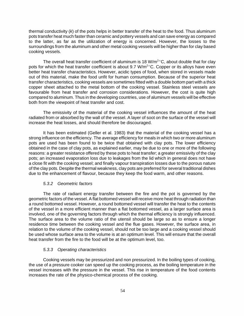
54
thermal conductivity (k) of the pots helps in better transfer of the heat to the food. Thus aluminumpots transfer heat much faster than ceramic and pottery vessels and can save energy as comparedto the latter, as far as the utilization of energy is concerned. However, the losses to thesurroundings from the aluminum and other metal cooking vessels will be higher than for clay basedcooking vessels.
The overall heat transfer coefficient of aluminum is 18 W/m2EC, about double that for claypots for which the heat transfer coefficient is about 9.7 W/m2EC. Copper or its alloys have evenbetter heat transfer characteristics. However, acidic types of food, when stored in vessels madeout of this material, make the food unfit for human consumption. Because of the superior heattransfer characteristics, cooking vessels are sometimes fitted with a double bottom part with a thickcopper sheet attached to the metal bottom of the cooking vessel. Stainless steel vessels arefavourable from heat transfer and corrosion considerations. However, the cost is quite highcompared to aluminum. Thus in the developing countries, use of aluminum vessels will be effectiveboth from the viewpoint of heat transfer and cost.
The emissivity of the material of the cooking vessel influences the amount of the heatradiated from or absorbed by the wall of the vessel. A layer of soot on the surface of the vessel willincrease the heat losses, and should therefore be discouraged.
It has been estimated (Geller et al. 1983) that the material of the cooking vessel has astrong influence on the efficiency. The average efficiency for meals in which two or more aluminumpots are used has been found to be twice that obtained with clay pots. The lower efficiencyobtained in the case of clay pots, as explained earlier, may be due to one or more of the followingreasons: a greater resistance offered by these pots to heat transfer; a greater emissivity of the claypots; an increased evaporation loss due to leakages from the lid which in general does not havea close fit with the cooking vessel; and finally vapour transpiration losses due to the porous natureof the clay pots. Despite the thermal weakness, clay pots are preferred for several traditional dishesdue to the enhancement of flavour, because they keep the food warm, and other reasons.
5.3.2 Geometric factors
The rate of radiant energy transfer between the fire and the pot is governed by thegeometric factors of the vessel. A flat bottomed vessel will receive more heat through radiation thana round bottomed vessel. However, a round bottomed vessel will transfer the heat to the contentsof the vessel in a more efficient manner than a flat bottomed vessel, as a larger surface area isinvolved, one of the governing factors through which the thermal efficiency is strongly influenced.The surface area to the volume ratio of the utensil should be large so as to ensure a longerresidence time between the cooking vessel and the flue gases. However, the surface area, inrelation to the volume of the cooking vessel, should not be too large and a cooking vessel shouldbe used whose surface area to the volume is at an optimum level. This will ensure that the overallheat transfer from the fire to the food will be at the optimum level, too.
5.3.3 Operating characteristics
Cooking vessels may be pressurized and non pressurized. In the boiling types of cooking,the use of a pressure cooker can speed up the cooking process, as the boiling temperature in thevessel increases with the pressure in the vessel. This rise in temperature of the food contentsincreases the rate of the physico-chemical process of the cooking.

55
A non-pressurized vessel with a tight fitting lid can greatly reduce the evaporation losseswhen the vessel is being heated up to the boiling temperature. During simmering, the role of a lidin reducing vapour losses from the cooking vessel is less decisive as the vapour is under pressureand can escape, especially when the lid is not tight fitting. Condensation of steam on the inner sideof the lid also takes place, which results in large losses through the lid to the atmosphere, if the lidis made from a conducting material. For example, it has been estimated that a 0.5 mm thickaluminum lid will loose approximately 700 W/m2 in still air as compared to 233 W/m2 when awooden lid, 3 cm thick, is used. If conducting lids are used, the power control of the fire becomesmore important as far as the reduction in heat loss during simmering is concerned.
The use of a so-called hay-box can also reduce fuel consumption considerably. A hay-boxis a container which is lined with some insulating material such as straw, other agricultural residues,waste paper, etc. Food is brought to the boiling point on a stove and is then placed inside the haybox. The food gets cooked by the residual heat of the food. In the boiling type of cooking, this isan important method for initiating energy conservation and time saving measures.
Thus, it can be concluded from this discussion that the use of proper cooking vessels,designed on the basis of the heat transfer and fluid flow considerations, can play an important rolein the conservation of energy.
5.4 Stove Construction
Cookstove construction methods are primarily dependent on the material of construction.Even the design of a cookstove itself is also influenced to a great extent by the material ofconstruction. In addition, the modes of fabrication, cost, efficiency, durability and safety of a stovedepend on the material of construction. Thus, proper selection of the stove construction materialis of paramount importance and is the first step towards the design and development of the ICS.
5.4.1 Criteria for selection of material(s), construction methods and strategies
The selection of materials of construction depends on a number of factors, which can begrouped into three main categories: economic factors, operational factors and design factors.
a) Economic factors
Economic factors include the cost and technological factors. The cost factor is one of themost important parameters from the point of view of affordability by the users in the developingcountries. The cost of the stove comprises material cost, fabrication cost and transportation cost.The technological costs, such as the method of fabrication and repair should also be taken intoconsideration, even at the conceptual stage as these have an important bearing on the overall costof the ICS (see also section 3.4.4).
b) Operational factors
A biomass burning cookstove is subjected to severe operational stresses, which may bemechanical, thermal or chemical. The cookstove material should offer a maximum resistance to thesestresses. Some of the important parameters which need consideration are: strength, impact resistance,thermal stresses (steady/unsteady/shock) and phase stability at the operating temperature. Theresistance to thermal loss is also important from efficiency and safety considerations.

56
Type of material Malle-ability
Impactresistance
Thermalshock
Cost Insulationproperties
Long termstability
Productionfacilities
Cast iron G G G M P G Factory
Steel M G G G P M Artisan
Aluminum G M G M P M Factory
Unfired clay G P P G G M Built insitu
Fired ceramics G M P G M M Potters
Cementitious materials G M M M M M Fac./Artis.
Note: G denotes Good, M denotes Medium and P denotes Poor.
Table 5.3 Properties of stove construction materials
The cookstove material is also subject to severe chemical stresses which manifest themselvesin different forms of corrosion, especially mild steel. This problem gets compounded due to the hightemperature. These issues must be taken in to consideration in the selection of the material.
c) Design factors
In some designs, a number of the stove components may have intricate shapes, while inothers the leakage in and out from the stove may pose a serious concern. Thus, the malleabilityof the stove construction material also plays an important role with respect to these issues.
The stove construction materials can be divided into two main categories, namely: metalsand non-metals. Metals can be further subdivided into other categories, namely: galvanized or non-galvanized sheet metals, cast iron, aluminum, etc. Non-metals are ceramic, fired clay, mud, etc.Besides, there are hybrid stoves which are made out of a combination of materials either metal andnon-metal or from combinations of materials from the same group.
5.4.2 Construction problems and prospects
The relative advantages and disadvantages of different construction materials, with respectto different properties, can be shown as in table 5.3.
It can be concluded from the table that clay and cast iron have the most favourableproperties for the construction of stoves. That is the main reason for the widespread use of castiron to construct stoves, in particular in developed countries, where cost considerations are not anoverriding factor. On the other hand, clay which is available at no cost is the most preferredmaterial in the developing countries. However, hybrids like metal clad ceramics and/or castableceramics have shown great promise as a material for stove construction as these combinations canovercome some of the drawbacks of both the categories.
Clay stoves such as mud, mud/brick, mud/stone stoves, etc. are widely used in most of thedeveloping countries. This is not only because of the low cost and high availability, but also due tothe ability of the artisans or the owners to build the stove without any direct financial cost.

57
Soil type Mixing Proportion
Clay soil % Sand % Clay/sand mix ratio
Pure clay soils 15-25 75-85 1:5 to 1:3
Clay/sand soils 25-35 65-75 1:3 to 1:2
Clay/silt soils 25-35 65-76 1:3 to 1:2Source: VITA/ITDG, 1980
Table 5.4 Suggested mixtures of soil/sand
In spite of these advantages, clay has certain inherent problems. Its properties differ fromplace to place due to variations in the proportion of different components of the clay such as clay(particles smaller than 2 µ), sand (particles with a size over 20 µ, and silt (particle size between thatof clay and sand). With too much clay, the mass dries quickly, shrinks a lot (often unevenly) andis prone to cracking. Too much sand will make the stove more fragile, while too much silt resultsin flaking of the surfaces in contact with the flame and hot gases.
However, the properties of the clay can be favourably modified by adding one or more ofthe deficient components or some additional additives. For example, in the absence of clay,molasses or raw sugar can be used as a binder. The following mixtures have been suggested byVITA and ITDG (1980), as shown in table 5.4.
Cookstoves made out of un-fired clay deteriorate quickly as water (in the form of rain ormoisture in the atmosphere), food and water spilling during cooking, the constant exposure to hightemperature and the stove being knocked by the cooking vessel results in erosion of the clay. As aresult, the critical dimensions of some of the stove components such as pot seats, tunnels and baffles,for which the retention of the shape is very important for obtaining high performance, are easily altered.
These problems can be solved by the development of fired clay/ceramic stoves and liners.These stoves can be mass produced in industrial establishments or by village potters, on adecentralized basis. However, the preparation of a proper mixture and composition of the clay to makethese types of stove, is extremely important. The mix should have a sufficiently high amount of non-claymaterials (sand, grog, etc.) as this will improve the resistance to thermal shock, a major reason whyceramic stoves often fail. The production of ceramic stoves, in particular from clay which has a highnon-clay content, requires considerable skill. Fortunately, the firing temperature range of kilns used bythe traditional potters and the tile factories, is quite low and this helps in making a more heat resistantstove. Research has shown that stoves fired at relatively low temperatures, 700-800EC, have a betterthermal shock resistance than those fired at higher temperatures (HSE, 1992).
5.4.3 Construction technologies
As stated above, the technologies for construction are dependent on the material ofconstruction and the scale of production (owner, artisan, factory based). Various issues involvedpertaining to these technologies are discussed below.
a) Metal stoves
Metal stoves can be fabricated from metal sheet and or cast iron. Sheet metal stoves canbe fabricated at a central location in a factory or by an artisan. Factory based production systems

58
have the advantages of rapid production, quality control and relatively low cost. However, less jobopportunities are generated per unit produced as compared to artisan based or dispersedproduction systems. Keeping in view the large number of unemployed in most developingcountries, there could be socio-economic fall outs. In addition, in these developing countries thereare often transportation bottlenecks which will create considerable problems in ICS dissemination.In the case of metal stoves, if the design of the top/bottom plate is intricate or the shapes arecontoured, expensive stamping equipment and dies and large power load are required. On theother hand, simple shapes can be fabricated by an artisan using simple sheet metal working toolslike cutters, shears, hammers and riveting or welding equipment. Corrosion problems are quitecritical in sheet metal stoves. A suitable thermal resistant enamel/paint can enhance the life of thesteel, by inhibiting corrosion.
b) Clay stoves
The relative advantages and disadvantages of clay as a material of construction have beendiscussed in the previous section. The properties of the clay composite depends on the relativeproportion of clay, sand, and silt. Clay is responsible for plasticity and cohesion, while sand and siltprovide grittiness and smoothness.
Clay based stoves can be built by the block, mould and the pre-fabricated clay slabmethods. In the case of the block method, a block is prepared from the clay containing choppedagricultural residues as reinforcement, and cow dung as a binder. It is allowed to dry for some timeand the pot holes, tunnels and baffles are carved out with the help of a sharp blade. In the mouldmethod, internal metal moulds are set as per design in a box. Prepared clay is packed aroundthese and is allowed to set. After initial setting, the moulds are removed, dressed and the stove isallowed to set. The third method involves the placement of prefabricated slabs in the requiredconfiguration and these are plastered with prepared mud.
Although these mud based stoves have a short life span, they have the advantage of beingbuilt by local artisans or the users themselves. These provide opportunities for maintaining localskills and/or employment and expensive tools are not needed. Maintenance can be done at locallevel using local materials.
c) Ceramic/fired clay stoves
Ceramic stoves require special refractory clay or the local clay has to be modified withadditives such as rice husk ash, grog (fired clay in powder form) to improve the thermal andmechanical shock resistance. The main function of the grog is to disrupt the organized structureof fired clay body so as to arrest the propagation of cracks. Ceramic stoves can be moulded infactories using mechanized equipment. They are fired in specially designed kilns which can beregulated according to the time/temperature firing schedule.
On the other hand, fired clay stoves can also be made by the traditional potter usingtraditional tools like a potter's wheel and a traditional kiln. In order to increase the quality andproductivity, both these equipments can be modified. Besides helping maintain the traditionalcrafts, ICSs prepared by the traditional potters have the advantage of generating local employment,eliminating transport bottlenecks, and ease of maintenance .

59
5.5 Improved Cookstove Testing
5.5.1 Why test cookstoves?
The testing of an ICS involves a systematic approach to the evaluation of the useful andadverse characteristics of a particular model. It is helpful for comparing different models from theend-use point of view, or for selecting one model from the wide range of models available. Testingalso helps in gaining in-depth knowledge about the performance of the individual componentswhich is useful for undertaking further design modifications or incorporating other design features.It allows a better understanding of the processes of combustion, heat transfer, and fluid flow takingplace in the stove from the point of view of heat utilization. Without testing it is not possible toquantify the observations on the parametric studies for further evaluation. It will permit thecomparison of the results of tests conducted at different places. Thus testing is one of the mostimportant tools from the points of view of quality control and design. It also helps in thedissemination of the technology, by demonstrating to the user the relative advantages of efficientmodels. In spite of these implications standardized testing methods have yet to be established toafford a universal comparison.
5.5.2 Criteria for testing
Keeping in view the above discussion, a versatile test procedure should have the followingfeatures:
a) The test should be simple and easy to perform, at different stages such as in the laboratory,factory, and field.
b) The results of the test should be easy to interpret by the different actors such as:developers, research scientists, implementors, public opinion makers, planners, and theusers.
c) Results should be reproducible, within reasonable limits. d) The test should be versatile so that it is applicable to a wide range of end use applications. e) It should be able to simulate cooking, as closely as possible. f) It should be able to predict the effect of different parameters which influence the
performance of the stove.
An analysis of the above mentioned requirements indicates that it is not possible to achieveall the objectives within only one test. This is why there have evolved so many test methods andwhy a number of indices for evaluating the performance of ICS have been proposed.
5.5.3 Indices for testing
The indices proposed for testing the stoves are: the overall thermal efficiency or first lawthermal efficiency; the second law thermal efficiency; the specific task fuel consumption and thespecific per day fuel consumption.
! Overall thermal or first law efficiency. This indicates the energy-wise performance of thecookstove. It establishes the ratio between the energy output to energy input.
! Second law thermal efficiency. This is a measure of the task index and is the ratio of theactual work output to the maximum work for the same task.

60
0 ' n × M × cp (96 & Ta) % M ×cp (Tb & Ta)
Hc× W (5.14)
0 'M × cp × )T × tt
tm × W× Hc (5.15)
! Specific task fuel consumption. This is defined as the measure of fuel required per unit taskoutput. A task could be cooking a standard meal or producing a jaggery batch, etc.
! Specific per day fuel consumption. This is the ratio of the fuel used over a period to carryout a specific task such as cooking meals for a number of persons over the number of daysin that period.
For other tests such as on the combustion quality, the stove safety test, material ofconstruction, etc, the reader may refer to test methods as approved in the India and Chinacompendiums (FAO/RWEDP, 1993a, 1993b).
5.5.4 Overall thermal efficiency testing methods
A number of methods have been proposed to evaluate the overall efficiency of thecookstove. These are: (1) constant heat output method,(2) constant temperature rise method,(3)water evaporation method,(4) constant time method,(5) cooking simulation test,(6) processsimulation test for non-cooking stoves. These are described below:
a) Constant heat output method
A known amount of water at ambient temperature is heated in a pot on the stove till itattains a temperature of 96EC. At this point it is replaced by another vessel with the same quantityof water at ambient temperature. The process is repeated till the completion of the combustion
process. The efficiency, 0, of the process is calculated as:
where M is the quantity of water in each pot, Ta and Tb are the ambient temperature and the highesttemperature attained by the last pot. Hc is the heat of combustion, W is the amount of fuel burnt, n isthe number of times cold vessels have been placed on the fire and cp is the specific heat of the water.
b) Constant temperature rise method
This method is similar to the constant heat output method except that the fixed quantity of wateris heated through a fixed rise in temperature )T (e.g. 20-30EC) and time t required for this rise ismeasured. Experiments are repeated a number of times and the average time tm is calculated.
where tt is total time during which heat output is measured.
c) Constant time method
In this method a fixed quantity of water, M, is heated for a fixed time, tc, and the rise intemperature is noted. The process is repeated and an average temperature rise, Tave, is calculated:

61
0 ' M × cpTave
Hc× W ×
tc
tt(5.16)
0 'M × cpl × (Tb&Ta) % M1 × cpv (Tb&Ta) % M2 × HL
Hc × W (5.17)
where tc is the constant time interval and tt is the total time.
d) Water boiling test
The water boiling test is a laboratory test which can be used to compare the performanceof two or more stoves under similar controlled conditions, or the same stove under differentconditions. It simulates the boiling/simmering type of cooking to some extent only. As a result, itdoes not necessarily reflect the actual stove performance, when food is cooked. A known quantityof water is heated on a cookstove. The volume of water evaporated after complete burning of thefuel is determined. The thermal efficiency, 0, is calculated as:
where M is the mass of water initially in the cooking vessel, M1 is the mass of the vessel and M2
is the mass of water evaporated. Cpl, Cpv are the specific heat of the water and the specific heat ofthe vessel, respectively, and HL is the latent heat of vaporization.
In order to simulate the actual process of boiling in a cooking process, which comprisescooking and simmering, the water boiling test has been modified.
In the modified method, the total test period is divided into two parts, namely, the highpower phase (heating or cooking period) and the low power phase (simmering period). The ratingof a cookstove is good according to this method if a certain mass of water can be quickly boiledduring the high power phase and a small quantity of fuelwood is used during the low power phase.The performance of different stoves is evaluated by estimating the thermal efficiency, the specificstandard consumption and the power output of the fire (PH) during the high power phase. Duringthe low power phase, efficiency measurements are not taken, only the power output of the fire (Ps)and the specific fuel consumption is taken into consideration. The specific fuel consumption in thisphase is defined as the amount of fuelwood required to keep a known quantity of liquid just belowboiling point for a specific period of time.
The higher the ratio of maximum to minimum power output (defined as the turn down ratio),the greater is the potential for fuel saving. The results of the water boiling test depend on a numberof factors, both controllable and uncontrollable:
! Fuel conditions - Fuel surface to volume ratio and the calorific value, density and moisture.
! Load conditions - The number of vessels, the mass of the vessels, the thermal mass of thevessel, the thermal conditions of the vessel, the thickness of the vessel, the specific heatof the vessel, the exposed surface area of the vessel, projected area of the vessel whichsees the flame, the emissivity of the vessel material, the area of water evaporation surface,the thickness of the soot deposits, the presence and absence of lid and the lid material andfinally the cooking substance properties.

62
! Environmental conditions - Air temperature, water temperature, wind velocity, atmosphericpressure, relative humidity and the kitchen environment.
! Operating Conditions - The feeding and burning rates, the flame temperature, the mass of
water load, the accuracy of measuring instruments and the age of the cookstove (as thematerial may become degraded with use).
A detailed analysis of the effect of some of these factors on the overall efficiency isavailable in the literature (Bialy 1986a, Bhatt 1983, Geller 1983, and VITA 1985). Out of all thethermal efficiency tests mentioned above, the water boiling and specific fuel consumption methodsare the ones which are most frequently used to determine the thermal efficiency of the stove. Thisis because the constant temperature rise method and the constant time method are onlyapproximate methods, while the constant heat output method is time consuming.
5.5.5 Specific task fuel consumption or cooking test
Cooking tests are performed in order to evaluate the performance of a cookstove whileactually cooking food. These tests differ from the water boiling test in respect of the medium towhich the heat is transferred. In contrast to water in the water boiling test, food is used as amedium in cooking tests.
Water boiling and cooking tests also differ from each other on the basis of the final stateof the cooking substance. In water boiling tests the onset of boiling is the final stage. However, thefinal stage in cooking is difficult to define as it depends on the perception of the user. It makesthese tests user- specific in nature. Cooking tests can be performed in the laboratory, as well asin the field and involve the preparation of standard meals (preferably by the real user or the cook),adopting the culinary practices of the target groups. These tests shed light on different componentsof the cooking process such as the stove performance, cooking process, fuel used and the timespent during cooking, as well as general observations on smoke and heat emissions. Controlledcooking tests are dependent on a number of factors:
! Composition and physical properties of food, ! Type of cooking operation, ! Mass of food to be cooked, ! Method of preparation of food, ! Type of vessels used.
Within the controlled cooking tests there are again variations in the tests. The controlledcooking tests can be further sub-divided in:
! Single food cooking test, ! Single meal test, ! Full day cooking test (kitchen performance test), ! Process simulation test.
In order to evaluate the relative performance of the cookstoves, it is essential that in allcases the controlled cooking test should be conducted in such a manner that at least thecontrollable factors, as mentioned above, are kept constant as far as is possible.

63
0 ' j mj'1
j ni'1
mi × cpi × )T % mi × pi % mw × L
W × C(5.18)
a) Single food cooking test
This test involves the cooking of a single item of the meal. It is the simplest form of thecooking tests.
b) Single meal/controlled cooking test
In this test a standard meal is defined on the basis of the requirements of the target groupand the quantity of fuelwood required to prepare the standard meal, consisting of various dishes,is determined. It is normally conducted in a laboratory or in the field (actual kitchen) by trained staffwho know how to cook traditional dishes. The main aim of this test is to evaluate the relative useof fuel and time in cooking a meal on different stoves and to gauge the ability of the stove toeffectively perform the culinary practices of the target group. This test is more complicated thanthe single food cooking test as the preparation and cooking of a full meal is more difficult to controlthan cooking a single food item. In contrast to the rigidly fixed test procedures in a water boilingtest, flexible procedures are used for the controlled cooking test depending on the type of mealcooked, the stove design and the manner in which the stove is used. However, for consistentresults, efforts are made to keep constant those variables which influence the fuelwoodconsumption during the cooking process. These are the shape and size of the cooking vessels andthe type and size of the fuelwood. This is done by preparing the same meal, in the same type ofpot, at the same location and time, and in the same way. The cooking efficiency is calculated bythe following equation:
where cpi is the specific heat of each food item, pi is the heat of chemical reactions occurring duringthe cooking process per unit food item, mw is the mass of water evaporated during cooking, idenotes constituents of one food item and j denotes each food item.
The results of controlled cooking test are comparable, when the same sequence,procedure, and conditions are used.
c) Specific per day fuel consumption test/controlled kitchen performance test
This is a field test in which the relative performances of two stoves, in terms of fuelwoodconsumption, when used under normal household conditions are compared. The results of this testestablish whether a new stove is actually capable of saving fuel. This test takes into accountdifferent cooking tasks, such as baking, frying boiling, food reheating, tea preparation, milk boiling,preparation of snacks, etc., performed during the day. This test simulates the actual use of a stovemuch better than a single meal test. However, much more effort on measurements as well as skillsis needed to perform this test. Before performing this test, a typical schedule of meal andoperations and their relative timing is established. The mass of the food items, the cooking vesseland the stove design are also fixed.
The fuel consumption of a family is measured over a period of several days, with traditionalas well as improved stoves under actual living conditions and is then compared with each other.Controlling factors, such as the number of persons which take a meal, the type of food. Additionalchores performed, which influence fuel consumption should also be taken into consideration.

64
specific consumption per day 'kg fuelwood consumed in total days
number of persons × number of days (5.19)
In this test, the amount of fuelwood at the beginning and at the end of each test ismeasured. It is a prolonged test and the results are depicted in terms of specific consumption perday, which is defined as:
In this test, data should be collected from at least five households and the test should beconducted over a period of at least five consecutive days (preferably seven). The specificconsumption per day gives a good indication of the energy-wise performance of the kitchen, butdoes not reveal why and how.
The procedure for conducting the water boiling test, the controlled cooking test and thekitchen performance test have been described in “Testing the Efficiency of Wood BurningCookstove” (VITA 1985).
5.5.6 Test selection criteria
A critical analysis of the testing procedures of ICSs, described above, shows that none of thetests is complete in itself. Hence, a combination of these tests has to be used to study the completeperformance of an ICS. For example, the controlled cooking test is intermediate to the water boilingtest and the controlled kitchen performance test. The water boiling test is used for a quick evaluationof the stove design parameters. It is also used to study the effect of operational parameters such asfuel characteristics, burning rate, etc. on the performance of the ICS. Thus, the water boiling test canbe used not only to evaluate the relative performance of the different stoves, but also to help thedesigners optimize different parameters. Water boiling tests may simulate the cooking of food by theboiling process. However, for other cooking operations like frying, baking, smoking, steaming, etc.the performance conditions are entirely different and the water boiling test may not reflect the trueperformance index of the stove from the user's point of view.
While the water boiling test is performed according to a rigid format, the controlled cookingtest uses variable procedures depending on the type of meal cooked, the manner in which thestove is used and the intended design of the stove. This test completely simulates the actualcooking and the stove is subjected to more realistic, though controlled, conditions.
Controlled kitchen performance tests are performed after the controlled cooking test in orderto evaluate the energy conservation impact of the new stove on the kitchen energy use and gives farmore realistic performance results of the stove under actual conditions, than the controlled cooking test.
It can be concluded from the above discussion that the results of cooking tests areexpressed in terms of measured fuel consumption and/or specific fuel consumption, and efficiency.The measured fuel consumption is a valid parameter if the type and quantity of food cooked aresimilar. The specific fuel consumption (SFC) takes into account the variation in the mass of cookingsubstance if it is not very large. However, variations in the composition are not taken intoconsideration. Hence, the SFC should only be used as a criterion to compare the performance ofthe stoves if the foods cooked are similar. On the other hand, efficiency measurements take intoconsideration the variation in mass and composition of the food substance, and hence are a bettercriterion for measuring the performance of uncontrolled/controlled cooking tests.

65
Figure 5.2 Heat analysis NPIC2M
5.5.7 The concept of efficiency
The concept of efficiency is based on the thermodynamic considerations which are usedto evaluate the performance of a device. It is an engineering concept and according to the first lawof thermodynamics, the efficiency of a device for a specific operation, is the ratio of the energyoutput to the energy input. The second law of efficiency is the ratio of the actual work output to themaximum possible work output, for the same task. While the first law of efficiency gives the energy-wise performance, the second law gives the efficiency of the devices to perform a given task. Ina wood fired cookstove, heat is generated by partial combustion of wood. Some of the heat sogenerated is transferred, by radiation and convection, from the fire bed and the flue gases to thevessel, and some of it is utilized for cooking food. The remainder of the heat is lost to theenvironment, through various heat transfer mechanisms, as described in section 3.5.2. The finalresidual heat of the flue gases is lost to the environment by dilution. The heat balance of a two-potmud stove is shown in figure 5.2. Results of the thermal performance of a single pot cookstove andsimmering stove (Hara), a two pot medium size (NPIC2M) and a large size (NPIC2L), and a threepot medium size (NPIC3M) and a large size (NPIC3L) cookstove are presented in table 5.5(Sharma et al 1992).
A number of partial efficiencies have been defined (VITA 1985) taking into account theeffect of various losses that take place at different stages in a cookstove. These are:

66
Table 5.5 Results of the thermal performance of various stoves
Performance of Unified Model
Parametres Single pot Sohnihara NPIC 2M NPIC 2L NPIC 3M NPIC 3L
Surface area m² 0.38 0.28 0.79 0.84 0.91 1.02
Fire box area m² 0.017 0.027 0.035 0.044 0.039 0.032
Stove weight % 42 56 104 128 136 290
Useful heat % 25.15 24.36 23.48 25.68 27.0 28.65
Sensible heat gainedby pots % 0.1827 0.167 0.3643 0.1981 0.2846 0.2212
Radiation losses % 3.59 4.43 7.38 5.76 7.1 7.09
Convection losses % 1.34 1.69 3.26 2.20 3.73 4.10
Sensible heat gainedby stove % 4.20 8.01 12.36 18.93 18.33 39.09
Flue gas losses % 20.59 8.9 12.92 7.8 5.53 11.26
Heat lost as charcoaland ash % 3.02 6.3 1.77 2.91 1.25 2.70
Heat lost in evap. Ofmoisture in fuel % 0.79 0.79 0.79 0.79 0.79 0.79
Heat lost to moisturefrom H2 in fuel % 3.93 3.93 3.93 3.93 3.93 3.93
Heat lost due to CO % 0.00088 0.0101 0.0015 0.0013 0.0015 0.0388
Unknown losses % 37.2 41.5 33.8 39.8 32.0 1.4
CO % 0.08 2.7 0.13 0.12 0.26 0.04
CO2 % 3.4 5.9 3.0 3.1 6.1 3.4
CO/CO2 % 0.024 0.046 0.043 0.039 0.040 0.012
Charcoal g 5 85 5 25 0 10
Ash g 50 10 25 35 25 60
Flue gas temperature EC 241 250 138 95 121 125
Burning rate kg/h 1.0 1.5 1.0 1.5 1.0 1.5
(i) Combustion efficiency: 0c 'heat generated by combustion
energy potential in fuelwood
(ii) Heat transfer efficiency: 0t 'gross heat input to the pan
heat generated
(iii) Pot efficiency: 0p 'gross heat input & surface losses
gross heat input

67
SC 'mass of fuelwood consumed
mass of food cooked(5.20)
0 '1
SC×
cpf × )T
Hc(5.21)
(iv) Central efficiency: 0r 'heat absorbed by the food
net heat input to the pot
(v) Overall efficiency: 0' 'net heat absorbed by the pot
energy potential in fuelwood' 0c @ 0t @ 0p
(vi) Cooking efficiency: 0c ) 'heat absorbed by the food
energy potential in fuelwood
The thermal efficiency of a device could be based on the measurements of steady state orunsteady state operations. In the case of steady state operations, the measurements can be takenat any given moment, while in the case of unsteady state operations, the input and output valuesare measured and integrated over the entire process. Most of the real life processes fall under thesecond category. Another index of performance is the specific energy consumption which isdefined as the amount of energy input required to perform a given task.
While applying these indicators, it should be kept in mind that efficiency is not an absolutephysical quantity but a self-defined ratio which depends on the conditions under which a processtakes place and how input/output are measured, thus serving only as a guideline. Efficiency maybe reproducible in a system having a standard performance like an internal combustion engine.However, combustion of biomass in a cookstove is a variable process because thermodynamicefficiency of a cookstove depends upon a large number of factors such as stove design, fuelcomposition, vessel design, culinary practice, meteorological conditions and operational variablessuch as fire tending and rate of heat supply, etc. Most of these factors are variable in nature andhence the thermodynamic efficiency of a cookstove is not a unique property of the cookstove.Thus, it has a limited utility and cannot predict the actual fuel consumption. The efficiency is adesign tool rather than a means of predicting field performance of ICS.
The stove performance can also be expressed in terms of specific consumption (SC) whichmeasures the fuelwood required to produce a unit output. For cooking, this can be expressed bythe equation:
There is a link between SC and the cooking efficiency which can be expressed as shownin the following equation:
Where cpf is heat capacity of specific food and Hc is the calorific value.
The specific consumption appears to be a better index for expressing the performance ofa cookstove and describing the wood consumption pattern, for planning exercises. During thesimmering operation in water boiling tests, the efficiency is close to zero, while the SC will not

68
become infinity. Results of the water boiling tests show that the overall efficiency and the specificfuel consumption show a similar trend.
It can be concluded from the above discussion that the cooking efficiency can be checkedmore realistically in controlled cooking tests. In order to draw realistic conclusions, the water boilingtest, specific fuel consumption, turn down ratio, as well as the evaporation rate should also bespecified.

69
6 ENVIRONMENTAL AND HEALTH IMPLICATIONS
6.1 Environmental Issues
There are two main environmental issues related to biomass conservation (especially thetree/forest biomass): its generation and maintenance and its sustainable use for various purposes,including fuel. While many contributions to the environment from the generation of trees have beenwell- recognized, the use of tree products, unfortunately, is generally considered problematic toconservation and as such people are often discouraged from their immediate or future use. Thepersistence of the tree/forest preservation bias is considered a major constraint in the developmentof a conservation strategy in which the need for tree products for local people's daily survival andproductive activities is recognized.
As numerous economic and socioeconomic benefits can be derived from the sustainableutilization of trees and wood products, both at micro and macro levels, it is essential to establish a longterm perspective on the wise use of the valuable resource in which people themselves could fullyparticipate in their production, maintenance and use for their own benefit as well as the nation's.Biomass/wood energy development, as a part of this long term strategy, has an important role to playin serving both rural and environmental development goals in most developing countries, if not all.
In the rural domestic sector, especially in many populated Asian countries (eg. China, India,Bangladesh, Nepal, Pakistan and Vietnam), rural people are adopting much poorer quality, morepolluting fuels for cooking, such as dungs, crop residues and grasses. This is largely the result oflong neglect and/or poor management of land and land based resources. To help these peoplereturn to fuelwood use is desirable. From the health point of view, such a movement back to woodwould be of great benefit to rural development, since nearly two billion Asian rural people still livein very poor cooking conditions.
6.2 Health Effects Related to Domestic Biomass Fuel Burning
Table 6.1 shows health implications of major pollutants that are normally emitted from biomassburning. Figure 6.1 shows the potential of CO toxicity according to concentrations and exposure time.
Although a number of studies have been carried out in developing countries (China,Guatemala, India, Kenya, Nepal, Papua New Guinea, Zambia, etc) on the health effects relatedto indoor air pollution as caused by biofuel cooking, the subject is not fully understood. The mainreason for the inconclusive nature of the evidence is an insufficient database and the uncontrollednature of these studies, conducted over a short period of time. In addition, many other confoundingfactors on health (besides indoor pollutants) are also common and there are difficulties inconducting a study which requires the comprehensive establishment of past health records,behaviours of the subjects and lengthy monitoring of their related activities.
Despite some knowledge gaps, the World Health Organization, based on a consultation(WHO 1992), concluded that “there is growing scientific evidence to support the numerousanecdotal accounts relating high biomass smoke levels to important health effects”. At the sametime, it admitted that “more research is sorely needed”.

70
Pollutant Mechanisms of health effects
Carbon monoxide Inhalation into respiratory systemAbsorption into blood from lungsElevated carboxyhemoglobin (HbCO) levelsReduced oxygen to body tissuesPossible cilia-state impact on lung clearance
Particulates Inhalation into respiratory systemDeposition in respiratory tractIrrigation and toxicity
Benzo (a) pyrene Inhibition into respiratory systemDeposition and absorption in lungsMetabolic activationPrecursor to cancer
Formaldehyde Irritation of mucosaToxicity to ciliaReduction in lung clearance abilityPossible carcinogen
Source: Smith, 1987
Table 6.1 Mechanisms of principal health effects from major pollutants
Figure 6.1 Effect of carbon monoxide concentration in the atmosphere as a function of exposure time forvarious conditions of labour.

71
Based on those studies mentioned above, two types of respiratory diseases related to biofuelburning smoke have been established, namely: Chronic Obstructive Lung Disease (COLD) in adultsand Acute Respiratory Infections (ARI) in infants and young children. Both of these diseases areprevalent among families using biofuel in traditional open-fires or traditional stoves in unventedconditions. “Cor Pulmonale” (heart disease secondary to COLD) has also been found to be prevalentand to develop earlier than average in non-smoking women who cook with unvented biomass stoves(Pandey 1988). Other health effects such as adverse pregnancy outcome (low birth-weight), cancer,etc. are also suspected from biomass burning smokes (tobacco smoking as well as unvented cookingfire). For detailed discussions on biofuel and health, please refer to Smith (1987), WHO (1992).
Pandey (1985), studied the impact of domestic smoke pollution on the respiratory functionsand established a direct link between smoke pollution and chronic bronchitis. His study showed apositive interaction between domestic smoke pollution as well as tobacco smoking on lung function.Another study undertaken in rural China, where fuelwood, crop residues and coal are used inhouseholds (WHO 1992), reported that among the first ten causes of death of rural Chinese,respiratory diseases rank first, with a mortality rate 73% higher than their counterparts in cities, inspite of a much worse level of outdoor air pollution in cities. Smith (1986) studied the exposure ofwomen to indoor air pollutants, during cooking on traditional stoves using biomass fuel, in four Indianvillages. It was found that total suspended particulate (TSP) exposure averaged nearly 7 mg/m3 andbezo-a-pyrene (BaP) about 4,000 mg/m3, which is many times more than the permissible limits. Inaddition, due to improper ventilation and air movement in the kitchen, women and children areexposed to the combined effect of elevated temperature and high humidity in the kitchen whichmakes working conditions very uncomfortable, especially in the hot and humid climates.
Studies conducted on the estimation of emission factors in traditional cookstoves using solidbiomass (Ahuja et al 1987), showed that CO emission ranged from 13-68 g/kg for fuelwood to26-67 g/kg for dung cakes and 20-114 g/kg for crop residues; for suspended particulates thevalues ranged from 1.1-3.8, 4.1-7.8 and 2.1-12.0 g/kg for these fuels, respectively. The resultshave indicated that emissions from both dung cakes and crop residues are 2-3 times higher thanfuelwood on a per unit heat delivered basis. Unfortunately, the predominant fuels used in the ruralIndian households are either dung cakes or crop residues (due to fuelwood resource scarcity).
This has resulted in a large build-up of the pollutants in the kitchen due to the inherent poorventilation conditions. This is the reason that the most prevalent polluted environment in the worldis to be found indoors, in the rural areas of developing countries. To a certain extent, it may affectthe health and productivity of the exposed masses of rural people in the developing world.
Data on smoke emission factors and exposure levels in various kitchen conditions rarelyexists. These studies have become more important in the light of evidence that clean combustionand thermal efficiency are often competing (see chapters 5 and 8).
Therefore, in order to evaluate the full implication of this problem, there is an urgent needto undertake controlled studies on different aspects of the occupational hazards of smoke. Acomprehensive programme should be carried out in earnest over an extended period tostudy/monitor the indoor air quality caused by biofuel cooking in different agro-climatic regions ofthe world so as to fully visualize the magnitude of health problems associated with it. The impactof meteorological and ventilation factors, which have a profound effect on the indoor air quality,also need in-depth study. Data on the relative importance of different variables, such as

72
environmental, thermal, social, ergonomical, hygienic etc., contributing to indoor air pollution islacking and needs comprehensive studies in order to come up with improved solutions.
6.3 Emission Characteristics of Biomass Fuels
In theory, the complete combustion of biofuel in a combustion device like a cookstoveshould result in the release of just carbon dioxide and water, which do not fall under the categoryof pollutants. However, it is very difficult to ensure complete combustion in traditional cookstovesand/or ICSs due to the heterogeneous nature of the combustion process, lack of proper control,and design constraints as explained earlier in chapters 3-5. Thus, the emission of pollutants duringsmall scale biomass combustion is unavoidable, in or outside the kitchen. The level of pollution willvary depending on the types of stoves and fuels used.
There exists a wide variety of biomass fuels that are used in cookstoves such as fuelwood,dung cakes, crop residues and grasses/weeds. Apart from these naturally occurring fuels, there areprocessed fuels such as charcoal and briquetted fuels. The physical and chemical characteristics ofthe fuel has an important bearing on the combustion characteristics and vary with the type of fuel.Physical and chemical properties of biomass fuel have been presented in detail in chapter 4.
While an ideal fuel and improved cooking system, suitable for rural people has yet to beevolved, the best strategy now is to reduce the products of incomplete combustion (PIC) from thecookstoves as much as possible. Additional discussions are also presented in section 6.4 below.
Table 6.2 shows the emissions from different types of fuels for three major applications:large scale industrial furnaces, small scale residential heating stoves and domestic cooking stoves.It is noted that the pollutants emitted as particulates, sulphur dioxides, nitrogen oxides,hydrocarbons and carbon monoxide are less in the case for larger scale combustion systems thanthe smaller ones. In fact woodfuel can be burned clean, compared to oil or coal, at a larger scale.Due to its small scale (1-5 kW power output) and short/intermittent operation in nature, it is difficultto always have complete combustion in the domestic cooking stove.
While observing that the quantity of pollutants emitted from biomass burning cookstoves, as shownin table 6.2, is relatively large, it should be pointed out that these pollutants, are based on traditionalcooking with thermally inefficient stoves operating mostly without sire grate.
The studies on the role of ICSs, in reducing the indoor air pollution level in Nepal showedthat the average exposure rate of total suspended particulates (TSP) dropped from 8.2 mg/cu. m.to 3.0 mg/cu. m. with the introduction of chimneyed ICSs. Carbon monoxide and formaldehydeconcentrations dropped from 82.5 ppm to 11.6 ppm and 1.4 ppm to 0.6 ppm, respectively. Theimpact of the use of ICSs on the indoor air quality was studied by Ramakrishna (1989). In herstudy, half of the 200 households investigated were using traditional stoves while the other halfwere using ICSs. Results of this study showed that the concentrations of CO in households usingICSs were much lower than in those using traditional stoves. However, no significant conclusioncould be drawn in respect of the degree of exposure to TSP. In a study conducted in Gujrat, India,it was found that in closing a 2 m² hole in the ceiling of a small kitchen, the air exchange ratedropped by a factor of 14 and the emission exposure to the cook increased by a factor of 8.

73
System/FuelEstimated
thermalefficiency
Fuel usedto deliver1 GJ ofusefulenergy
Particu-lates
grams perkg fuelburned
Sulphuroxides
grams perkg fuelburned
Nitrogenoxides
grams perkg fuelburned
Hydrocarbons
grams perkg fuelburned
Carbonmonoxidegrams per
kg fuelburned
Industrial (>20kW)
WoodBituminous coalResidual oilDistillate oilNatural gas
Residential (>5kW)
Heating stoves
WoodAnthracite coalBituminous coalDistillate oilNatural gas
Cooking stoves*
Wood (tropical)Cow dung (Hawaiian)Coal (indian)Coconut huskNatural gas
7080809090
5065658585
1515201580
89 kg43 kg33 lit.31 lit.28 m3
130 kg49 kg53 kg33 lit.30 m3
420 kg530 kg220 kg480 kg32 m3
66530.3
---
211
100.4
---
9201.2
35---
0.6184241---
0.24
3041---
0.66
107
---
4883
---
1.45.03.02.5
---
0.77.02.07.0
---
40.50.10.1
---
501.3
100.1
---
7.57
107
---
510.60.7
---
13020
1000.7
---
8083
120110
---
Source: Smith (1987)
Wood, 15% moisture (dry basis), 16 MJ/kgBituminous coal, 10% ash, 1% Sulphur, 29.2 MJ/kgAnthracite coal, 0.2% Sulphur, 31.5 MJ/kgIndian coal, 0.5% Sulphur, 23 MJ/kg
Hawaiian cow dung, 0.3% Sulphur, 15% moisture, 12.5 MJ/kgCoconut husk, 15% moisture (dry basis), 14 MJ/kgResidual oil, .944 specific gravity, 45.9 MJ/kg
* Excluding natural gas, cooking efficiency and emissions of biomass fuels and coal are based on traditional stoves without anygrate.
Table 6.2 Typical air pollution emissions for fuels and combustion systems
Development of ICSs as recently shown in India, China (FAO/RWEDP 1993a, 1993b) and inThailand (AIT 1993) have shown low CO emission values.
Despite the merits of ICSs and their achievement in enhancing cleaner combustion and/orthe evacuation of pollutants from the kitchen, from the environmental and health point of views, itis important to recognize that, technically, there are nearly 180 polar, 75 aliphatic and 225 aromatichydrocarbon compounds which have been identified in wood smoke (Smith 1987). Out of these,17 toxic compounds, which account for 4.8% of the particulate mass, have been designated as“priority pollutants” by US/EPA because of the evidence of their toxicity. Fourteen compounds,which make up 0.5% of the particulate matter are carcinogenic, while 6 are cilia-toxic andmucous-coagulating agents, and 4 are cancer initiating/cancer promoting agents. These emissionsare acidic in nature with pH between 2.8-4.2.
The exposure level to important pollutants and the duration of exposure has been studied ina number of developing countries, where biomass is used as a fuel. Data is presented in table 6.3.
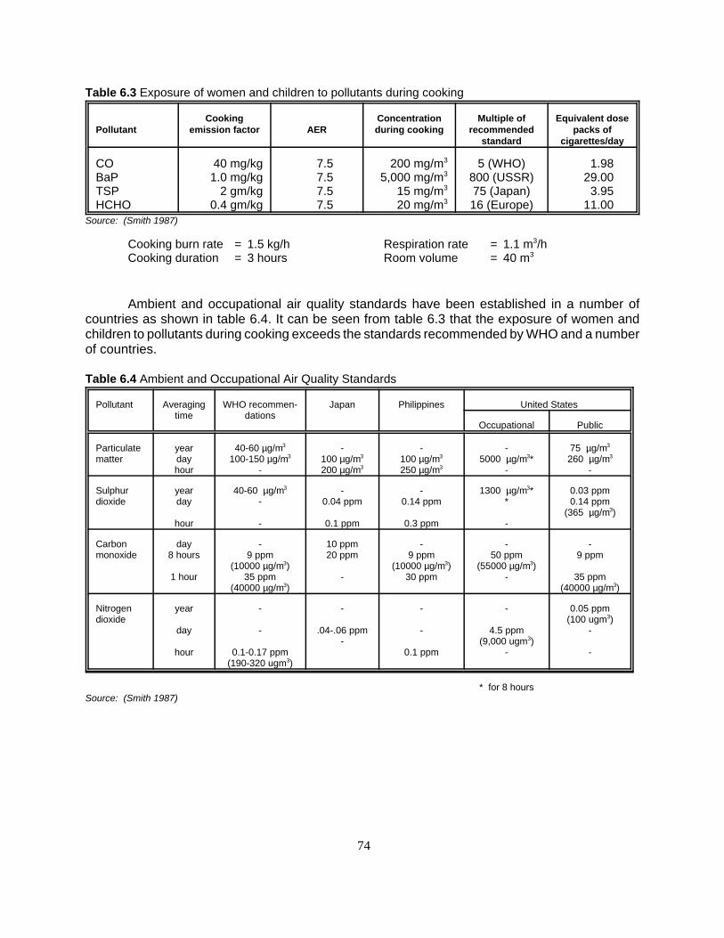
74
PollutantCooking
emission factor AERConcentrationduring cooking
Multiple ofrecommended
standard
Equivalent dosepacks of
cigarettes/day
COBaPTSPHCHO
40 mg/kg1.0 mg/kg
2 gm/kg0.4 gm/kg
7.57.57.57.5
200 mg/m3
5,000 mg/m3
15 mg/m3
20 mg/m3
5 (WHO)800 (USSR)75 (Japan)16 (Europe)
1.9829.00
3.9511.00
Source: (Smith 1987)
Cooking burn rate = 1.5 kg/hCooking duration = 3 hours
Respiration rate = 1.1 m3/hRoom volume = 40 m3
Table 6.3 Exposure of women and children to pollutants during cooking
Pollutant Averagingtime
WHO recommen-dations
Japan Philippines United States
Occupational Public
Particulatematter
yeardayhour
40-60 µg/m3
100-150 µg/m3
-
-100 µg/m3
200 µg/m3
-100 µg/m3
250 µg/m3
-5000 µg/m3*
-
75 µg/m3
260 µg/m3
-
Sulphurdioxide
yearday
hour
40-60 µg/m3
-
-
-0.04 ppm
0.1 ppm
-0.14 ppm
0.3 ppm
1300 µg/m3**
-
0.03 ppm0.14 ppm
(365 µg/m3)
Carbonmonoxide
day8 hours
1 hour
-9 ppm
(10000 µg/m3)35 ppm
(40000 µg/m3)
10 ppm20 ppm
-
-9 ppm
(10000 µg/m3)30 ppm
-50 ppm
(55000 µg/m3)-
-9 ppm
35 ppm(40000 µg/m3)
Nitrogendioxide
year
day
hour
-
-
0.1-0.17 ppm(190-320 ugm3)
-
.04-.06 ppm-
-
-
0.1 ppm
-
4.5 ppm(9,000 ugm3)
-
0.05 ppm(100 ugm3)
-
-
* for 8 hoursSource: (Smith 1987)
Table 6.4 Ambient and Occupational Air Quality Standards
Ambient and occupational air quality standards have been established in a number ofcountries as shown in table 6.4. It can be seen from table 6.3 that the exposure of women andchildren to pollutants during cooking exceeds the standards recommended by WHO and a numberof countries.

75
Figure 6.2 Generalised representation ofcomponent interactions in a domestic heatingoperation (Baily 1986b)
When cooking using traditional stoves, on average only 10-15% of the potential heat in thefuel is utilized by the pot for the actual cooking. The remainder of that potential heat (85-90%) isdissipated to the kitchen environment in the form of heat and smoke, resulting in the rise of thekitchen temperature and pollution to uncomfortable levels, especially where kitchen ventilation islacking. This situation also applies for many ICS models with no chimney and/or insulation, despitetheir double heat utilization efficiencies of up to 30-35%. In the boiling and steaming modes, forexample, a large quantity of the water used is dissipated in the form of steam, which drasticallyincreases the relative humidity in the kitchen. All these kitchen pollutants, including heat, steam,oil, and spice fumes not only render the air inside the kitchen unhealthy to breathe, but also makethe indoor environment very uncomfortable for cooks, especially in the humid tropical climates.
Therefore, it is important for development agents to be aware of and fully understand thissituation so that the assistance provided will lead to the alleviation of such a basic problem.
6.4 Strategies for Improvement of the Kitchen Environment
From the preceding discussions, thereappears to be an urgent need to save a largesection of the human population living in therural areas of the developing countries from theharmful effects of kitchen pollutants, emittedfrom solid biomass burning cookstoves andfrom unhealthy cooking practices. Figure 6.2below provides a general overview of thekitchen environment. Various strategies forimproving the kitchen environment are possible,such as: improved stove design, fuel upgrading,improved ventilation, and switching to cleanfuel.
6.4.1 Improved stove designs
Design improvements normally involvethe introduction of a chimney and theincorporation of other critical features forimproving both combustion and heat transferefficiencies. While combustion efficiencymeasures the extent of conversion of chemicalenergy to heat, heat transfer efficiencymeasures the fraction of the released heatdelivered to the pot and food. The emission of the pollutants is inversely proportional to thecombustion efficiency and the overall efficiency is inversely proportional to the amount of fuel used.A number of operational parameters, such as size and shape of fuel, burning rate, moisturecontents, excess air factor etc. are also critical. These must be optimized in the light of discussionsin earlier sections of this manual. Based on the application of these principles, a number of designsof improved stoves, with and without chimneys have been developed, and many have been widelydisseminated.

76
6.4.2 Fuel upgrading
As explained in section 4.1, solid biomass fuels contain a high percentage of volatilematters. The quality of combustion depends on the completeness with which the volatile matter isburnt. Hence, solid biofuels with less volatile matter, such as pyrolysed fuel, will burn cleaner.Changing over to the modified biofuel forms such as charcoal, torrefied wood, briquettes, biogas,alcohol etc. can improve the indoor air quality, due to less emissions. Use of catalytic convertersfor flue gas control can also help in reducing pollution from traditional biofuels. However, cost maystand in the way of their use.
6.4.3 Ventilation improvement
This can be a less expensive short term measure to improve indoor air quality, as simplechanges can have a large impact on air exchange rates and indoor concentrations of pollutants.Besides the kitchen door, windows, wall slits and other forms of ventilation should be encouraged.Wind directions will have an important bearing on the design of the kitchen and the installation ofopenings. More studies are needed to guide such improvements, scientifically.
6.4.4 Switching to other clean fuels
Cooking fuels, in gas form such as natural gas and LPG, in liquid form such as keroseneand ethanol, and in specialized form such as electricity, are more appropriate and usually preferredfor cooking in most societies. These fuels, in fact, already appear in the higher rungs of the fuelladder. Therefore, there exists a natural tendency of users to move up whenever such clean fuelsare affordable and accessible. However, in practice, a mass movement to these fuels is veryunlikely due to rural poverty and the poor country economic performance of the public and privatesectors. As witnessed today, fuelwood/biomass fuel is still widely used for domestic cooking in alldeveloping Asian countries (see chapter one).
Thus, it can be concluded from the discussion in this chapter that the effect of the pollutants(emitted from combustion of biofuels during cooking) on the health of women and children shouldbe of grave concern. There is a need to use various strategies, either singly or in combination tocurb the level of emissions. While designing improved cookstoves, it is essential to give as muchimportance to emissions as to thermal energy efficiency. There is a need to undertake a holisticapproach to pollution problems by studying emissions in various kitchen systems, instead of takingthe improved cookstove as the only major intervention.

77
7 THE KITCHEN: AN INTEGRAL PART OF THE COOKING SYSTEM
7.1 Kitchen and Stove Nexus
Because cooking is the most important chore in a household, the kitchen is the focalpoint of household activities. Cooking involves a number of functions including the preparation andcleaning of food ingredients, fuel preparation and firing, cooking of dishes according to fire intensityor custom, serving preparation, washing of utensils during cooking and after serving, kitchenclean-up, planning for future meals, etc. In addition to these main functions, there are also a numberof other supporting functions such as fuel collection and bringing water for cooking (both of whichoften require considerable travel), picking fresh vegetables/spices from home garden, milling ofgrains, etc. These activities are normally performed by women and/or young girls, especially in ruralareas of most societies. Furthermore, rural women often have to help or provide additional work onthe farm or earn supplementary income from various activities. In addition, due to high exposure tounhealthy kitchen environments (dark, smoky, hot and humid with poor ventilation), cookingconstitutes an occupational hazard for women. Due to their social obligation, most women rarely havetime for relaxation nor time to pursue income generation activities or education.
Improved cookstove development, as mentioned in chapters 1 and 2, began during the1950's for social reasons (smoke evacuation/health) and continued during the 70's from theperception of fuel scarcity and from the late 80's has become an integral part of a broader concernfor kitchens and the environment. A critical look at past ICS research and development workindicates that very little attention was given to important aspects of cooking beyond the stove itself,such as the conditions in traditional kitchens. Hardly any effort was made to integrate improvedcookstoves with improvements in the kitchen so as to gain overall energy efficiency, cookingproductivity, comfort and convenience.
However, as was stated at the Sub-regional Expert Consultation on improved cookstovedevelopment programmes in South-Asian countries held in Udaipur, India in 1991, the kitchen isnot only neglected in stove programmes. The culinary area or the kitchen plays a very importantrole in housing design but in practice the kitchen is often neglected, both in modern constructionand by housebuilders themselves (Nystrom and Jere, 1991). Despite considerable progress madein subsystem designs to increase the fuel efficiency and combustion efficiency and to removesmoke, a broader approach to the improvement of the domestic energy system (including the roleof women as kitchen managers), incorporating the kitchen element into improved cookstovedevelopment, has yet to evolve.
The first step in this direction is to understand the inter-relationship between the cookstoveand the culinary or kitchen system.
The culinary system has three components, namely: culinary area (kitchen), culinarypractice (food types) and culinary function (cooking operations).
Analysis of these three components shows that the ICS is linked only partially with theculinary system, which involves a large number of pre- and post-culinary functions also. Figure 7.1illustrates how the various components of meal preparation are related to each other and to thegeneral social context of particular communities at different levels

78
Figure 7.1 A circle diagram illustrates how components of meal preparation are related to each other and tothe general societal context at different levels.
Although the ICS does help in improving the indoor environment of the culinary area andreducing the time spent in cooking/collecting fuelwood, many users do not see any economic benefitsfrom the time saved nor perceive the pollution problem as dangerous, due to other benefits obtainedsuch as timber and thatch preservation, mosquito repulsion, fish/meat smoking, prevention ofinsect/rodent invasion on foodstuff, or their general acceptance of these conditions. Thusimprovement of the cookstove performance alone does not appear very attractive to the rural people.
In contrast, limited experiences from Nepal (RECAST/RWEDP, 1993) and Vietnam(Nystrom 1992) have demonstrated that the simple application of kitchen management principles,coupled with a few changes in the physical arrangement of the kitchens of rural women, were

79
Figure 7.3 Attributes of dependent componentsFigure 7.2 Attributes of operations and independentcomponents (Bialy, 1986b)
OPERATION
FoodProcessing
Waterheating
Spaceheating
People
Duration
Frequency
Time ofday
Lighting
MaterialCompositio
n
Age andsex
OPERATIONATTRIBUTE
INDEPENDENTCOMPONENT
House
COMPONENTATTRIBUTE
Key: Major data Minor data
INFORMATIONTYPE II
INFORMATIONTYPE I
Cookingof meals
Produce
Weight
PhysicalDimensions
FoodProcessing
Waterheating
Spaceheating
Lighting
Cookingof meals
Stove
Vessels
Food
Water
Fuel
Air
Moisturecontent
Physicaldimensions
Weight
Tempara-ture
Materialcomponent
OPERATION DEPENDENTCOMPONENT
COMPONENTATTRIBUTE
INFORMATIONTYPE III
Key: Major data Minor data
eagerly received. The application of this kitchen development approach, however, requires athorough understanding of the role of each component in upgrading the culinary system in thekitchen of rural people and it is clear that further research on this topic is required.
7.1.1 Stove functions
Bialy (1986b) describes in figures 7.2 and 7.3 energy use, the role and different functionsof a stove and its attributes of operations and its relations to various components.
7.1.2 Culinary functions
The first step in this direction would be to understand the role of the cookstove in theculinary functions. Culinary functions, as shown in figure 7.4, involve collection and storage (fuel,water, and food), food preparation (washing, cleaning, cutting and grading), firing stove, cooking,dining and washing of utensils. Most of these functions are overlooked or have not been taken intofull consideration in the designing of kitchens in most developing countries.
This is the major cause of poor working and sanitation conditions in the kitchen.Accumulation of solid, liquid and gaseous wastes generated from various cooking operations,especially cooking oil/spice fumes and odours and the absence of waste disposal provisions haveoften led the kitchen in many developing countries to be called the “dark place” of the house. Theworkload of women also increases due to lack of storage facilities and insufficient working spacein the culinary area. As a result, women, the casual cooks, are obliged to perform some of these

80
Figure 7.4 Culinary and related functions of a kitchen
functions outside the kitchen and hence make numerous trips to fetch foodstuff, vessels, fuel, wateretc. The trips would have been unnecessary if the kitchens were properly designed.
Apart from food, fuel and stove, supporting facilities such as a work bench, storageracks/cupboards (for food, utensils, fuel, etc.) and provisions for washing and a disposal systemfor waste material are also required to create an efficient kitchen, as shown in figure 7.5. Theplacement of the various utilities should be done from an ergonomic point of view after undertakingwork function studies which aim to enhance productivity and reduce the fatigue of the cook.Logically, housewives want to improve cooking performance and efficiency, so that their time andeffort can be minimized while overcoming problems related to health and cooking comfort. Byaddressing these issues in addition to achieving fuel saving and clean combustion objectives, ICPscan achieve the wide acceptance of appropriate ICS models.
7.2 Kitchen Design Considerations
Within a dwelling system, the character of the kitchen is important. A kitchen, separatedfrom a single family house, cannot be treated in the same way as a kitchen in an apartment or ina multi-story building. The location of the separate kitchen in relation to the rest of the dwelling iseasier to design than a kitchen in an apartment (Nystrom, 1992).
The placement of the kitchen vis-a-vis the rest of the building can have a profound effecton the quality of the indoor climate due to the transmission of heat and food odours, producedduring cooking, to the rest of the dwelling. Kitchens should not be placed adjacent to utilities suchas toilets and animal sheds. Some studies show that the kitchen should be separated from the rest

81
Figure 7.5 Supporting equipment and articles need also a place in the kitchen
Foodstorage
Watertank
Fueltank
Diningtable
Prep.table
outdoor
Prep.table
indoor
Stove Dishestable
Sink Dryingspace-rack
Equip-ment
storage
Cup-board
Sewagesystem
Ashbox
Wastebucket
Food
Water Fuel
of the building, especially in warm and humid climates and should be planned according toprevailing wind and ventilation considerations (Nystrom 1992).
The placement of the kitchen vis-a-vis the rest of the building can have a profound effecton the quality of the indoor climate due to the transmission of heat and food odours, producedduring cooking, to the rest of the dwelling. Kitchens should not be placed adjacent to utilities suchas toilets and animal sheds. Some studies show that the kitchen should be separated from the restof the building, especially in warm and humid climates and should be planned according toprevailing wind and ventilation considerations (Nystrom 1992).
The design of the kitchen must take into consideration the functions it is expected toperform for the particular group within society. Human movement patterns in the kitchen, which area function of culinary activities and associated practices, should be taken into consideration fordefining the working area of the kitchen. Special attention should be given also to the storage ofkitchen equipment, as it is important from an ergonomic point of view, and it should be placedaccording to the flow pattern for different activities (Nystrom. 1992).
The number and type of various utilities such as cookstove, work bench, storage cupboard,washing and waste disposal system should be located in such a manner that they cause leastdrudgery and ensure better hygienic conditions. Natural lighting and ventilation are two importantaspects in assigning space for various functions. Thus, the optimum design of a kitchen shouldtake into consideration the interplay between activities, equipment and the use of kitchen space

82
Figure 7.6 Cross ventilated kitchens and the placement of stoves. The kitchen should be placed accordingto prevailing winds (Nga and Nystrom 1990)
for various functions. There is also a direct relationship between the fuel choice and culinarypractices. For example, ergonomic studies show that the open-fire is more conducive to cookingin the squatting position while the standing position is preferred with kerosene and LPG.
7.3 Kitchen Air Quality
Indoor air quality in a kitchen can be improved by a number of strategies such as improvedstove design, fuel upgrading, and improved ventilation, as explained in section 4.6. The first twostrategies have been discussed in detail in that section. The improved ventilation strategy involves theprovision of a chimney or a hood to vent the smoke produced or to increase the air exchange rate.
Indoor air quality is a direct function of the air exchange rate (AER), which is defined as the rateat which the indoor air is exchanged with the outside air and it is expressed as the volume of airexchanged per unit of time. AER depends on the number and placement of window and door openings.In addition, meteorological conditions such as temperature, humidity and wind conditions considerablyinfluence the AER. Air exchange rates can be measured using different techniques such as the tracergas technique (Smith 1987) and the air pressurizing technique.
The passive tracer gas method has recently been tested in the research cooperationprogramme in Vietnam on" Kitchens, Living Environment and Household Energy". Measurements tookplace in an occupied flat and in an experimental flat. This method is useful but a drawback is that theanalysis can be made only in a few countries (Nystrom and Stymne, 1993).
It has been shown that, apart from the vent area/kitchen volume ratio, the AER is dependent onthe relative location of these openings. It has been further observed that in addition to prevailing windconditions, the channelling effect due to lanes and adjacent buildings has a profound effect on the AER.The position of the stove in relation to window and door openings in the kitchen is therefore importantfrom the indoo air point of view. From studies conducted at the Lund Centre for Habitat Studies (LCHS),it was concluded that the best location for the placement of a chimney is at the part of the kitchen whichhas least movement of air (Nga and Nystrom, 1990).

83
Figure 7.7 "Miniskirt model" with an upper part ofbamboo and lower part of concrete blocks
Figure 7.8 Hood from a pilot kitchen in Burkina Faso
7.3.1 Ventilation and buildingmaterials
Experiences from Nicaragua alsoshowed that the movement of air is differentin a room with bamboo walls that act asfilters from that in a room with solid bricks(Nystrom, 1991). Figure 7.7 shows a “mini-skirt” model which allows diffuse ventilationof the kitchen (Andersson, 1992)
7.3.2 Chimneys and hoods
Different types of hoods have beentested in pilot kitchens in Burkina Faso andVietnam. Development work is taking placein Vietnam concerning different passivesmoke evacuation systems. The so-called“Cooking Window” has given promisingresults and further design- and experimentson a full scale are being undertaken(Nystrom 1993).

84
Figure 7.9 The "Cooking Window" tested in Vietnam (Nguyen Trong Phuong, 1993)

85
8 IMPROVED COOKSTOVE AS COMBINED TECHNOLOGY
A large number of ICS models have been developed in different parts of the world. A numberof these stoves have consistently shown high performance in the laboratory as well as in field andhave been adopted by a large number of users. The major reason for the better performance ofthese designs is their better thermal and combustion performance. This has been accomplished bythe applications of different principles namely: heat transfer, combustion, fluid flow etc., as explainedin sections 3.5 of this manual, in addition to economic and social needs (section 3.4).
Different strategies adopted for improving the thermal efficiency of these stoves are basedon improving the thermal and the combustion efficiencies. Thermal performance of a stove isgoverned by the following equation:
Q = U * A * .. T . . . . . . .(8.1)
In order to increase the heat transfer to the pot, the overall heat transfer coefficient, U , areaexposed to the flame and flue gases, A, and flame temperature, T, need to be increased. Overallheat transfer coefficient, U, is mainly composed of convective and radiative heat transfercoefficients. Convective heat transfer coefficient can be increased by either increasing the velocityof the hot gases emitted in the combustion process or creating the turbulence in the heat transferzone. This can be done by forcing the hot gases to flow through a narrow channel beneath thestove, created by extending the rim of the stove.
Radiative heat transfer can be improved by improving the emissivity. Luminous flame hasa greater emissivity as compared to non luminous flame. However, luminous flame also resultsin greater soot formation, which will result in the loss of potential heat of the wood in the form ofunburnt carbon. Thus this strategy will not be very useful. However, radiative component of heatgain from the flame can be increased by increasing the temperature of the flame. This can be doneby increasing the flame temperature and increasing the shape factor. Flame temperature can beincreased by reducing excess air factor and preheating the air by making it flow through theannulus between the outer cladding and the combustion chamber. Excess air factor can bereduced by regulating the air entering the stove, either by the use of damper(s) or introduction ofadditional resistance in the flow passage(s) by modifying baffle design or tunnels. However,excessive control of air can increase emissions.
Heat transfer area can be increased by increasing the number of pot holes in the stove. Ina single-pot stove, the heat transfer area can be increased by lowering the pot in the fire-box andallowing the hot flue gases to pass around the pot. This can also be done by extending the rim ofthe stove around the pot.
Heat losses can be reduced by providing insulation on the outer surface of the stove, byusing low thermal conductivity material for construction, by providing cavity wall with air insulation,by avoiding massive construction wherever possible to reduce storage losses especially forintermittent cooking.
Many of the measures discussed above have been incorporated by different designers intheir models developed for increasing the thermal and combustion efficiencies, and reducing theheat losses. Most the designs of ICS developed by various developers can be grouped under fourcategories namely:
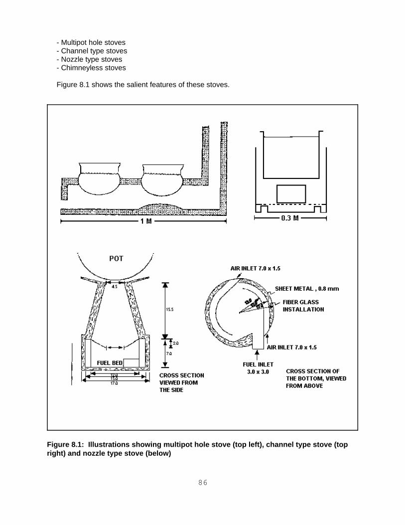
86
Figure 8.1: Illustrations showing multipot hole stove (top left), channel type stove (topright) and nozzle type stove (below)
- Multipot hole stoves- Channel type stoves - Nozzle type stoves- Chimneyless stoves
Figure 8.1 shows the salient features of these stoves.

87
8.1 Multipot Hole Stoves
In this design, two or more pot holes are provided so as to increase the surface area exposedto flame and hot gases, thus increasing the thermal efficiency. Major R & D efforts have beendirected towards the development of multipot stoves, due to the following reasons:
- ease of construction using local tool and skill,- use of locally available clay for fabrication, - ability to take pots of different shapes and sizes, - large fire-box to accommodate big size fuelwood and cowdung cakes,- ability to cook two or more items of food at the same time.
In a large number of the ICS models, most of the important components such as pot holes, tunnels,baffles, and chimney etc. have been designed after under taking detailed optimisation studies.
An example of this type of stove is "Rohini", the model developed by the author (Sharma 1990).This model has been designed for a medium size family, consisting of four to five members,especially in the hilly areas where water heating is required throughout the year. The stove can befueled with fuelwood, dung cakes and agricultural residues and has found wide acceptance in hillystates of India. More than 5,000 units have been disseminated in "Himachal Prades" alone. Theproduction cost estimate is Rs.55-80 (US$ 2.2-3.2).
In this model, heat transfer surface area has been increased by incorporating three pot holes.Two pot holes were designed for cooking operation, while the third was designed for heating water.The excess air factor was reduced by modifying the tunnels and baffles after undertaking detailedfluid flow studies. This innovation helped in eliminating the dampers which were used in most ofthe earlier models for controlling the draft for induction of air. Use of dampers had a number ofdrawbacks such as periodic manipulation, chances of burn injuries, difficulty in the puffing ofunlivened bread and excessive consumption of wood, when not used. Tunnels and baffles weredesigned in such a manner that the first pot hole received nearly 60% of the heat input, while therest was distributed in second and third pots. Radiative heat transfer was improved by optimisingthe view factor. Fire-box and air openings were designed for a burning rate of 1 kg/h. This burningrate was based on field studies carried out by the author to ascertain the average wood burningrate used in the target area by an average family. Detailed heat transfer analysis was undertakento study its performance at burning rates of 0.5 kg/h, 1.0 kg/h, and 1.5 kg/h. Results showed that
Table 8.1 Effect of the wood burning rate on the pot heating rate
Burning rate (kg/h)
Burning period (h)
Heating rate (oC/minl.)
Burning period Recovery period
I II III I II III
0.35 0.50 1.00 1.50 1.00
1.0 1.0 1.0 1.0 2.0
0.50.87111.281.69411.1666
0.42220.65551.33331.37141.5555
0.55 0.66661.60 1.15
1.5555
0.74281.17502.05714.93334.0277
0.18570.43330.74281.10 0.75
0.11660.28330.48570.34540.3

88
Figure 8.2: The Rohini three-pot stove
the efficiency of this ICS was not unduly affected by operation at wood burning rates lower thanthe intended design rate of 1kg/h. However, at higher burning rates the efficiency showed a fall,which can be attributed to the throttling affect of the tunnels and the baffles. This resistance wasintentionally introduced so as to cause back draft when excessive amount of fuel is charged intothe stove, which is the general tendency in the rural areas. Reverse flow of smoke through the fire-box gives a visual indication to the user that she/he is using more fuel. During optimisationstudies, it was noticed that the height of the tunnel from the bed in the fire-box influences the heattransfer to the pot very much. This can be attributed to the changes in the flame configurationbrought about by the changes in the tunnel configuration. Drawings of Rohini model are shown infigure 8.2 and selected test results are given in tables 8.1 and 8.2.
8.2 Channel/Shielded Fire Stoves
In channel type or shield-fire stoves, hot combustion gas is forced to pass through a smallannulus between the cylindrical fire-box and the cylindrical side of the pot. This increases the

89
Figure 8.3: Channel efficiency as a function ofchannel length for various channel widths (Baldwin1986b)
Table 8.2 Variation of heat gained by individual pots with wood burning rate
Burn-ingrate
(kg/h)
Burn-ing
period(h)
Char-coal(g)
Burning period Heat recovery period
Totalusefulheat
(kcal)
% heat gainedby each pot
Totalusefulheat
(kcal)
% heat gainedby each pot
I II III I II III
0.350.501.001.501.00
1.01.01.01.02.0
101565
100 40
293.7412.0886.0
1,040.11,737.8
69.3667.5056.0965.3358.55
19.4122.7928.1725.1829.35
11.23 9.7115.73 9.4912.11
36.068.5
120.4309.8307.6
72.2268.6164.2974.4472.72
18.0618.9821.5917.6914.76
9.7212.4114.12 7.8812.52
velocity of flue gases and enhances the heat transfer coefficient. However, fraction of the totalthermal energy of the gas entering the channel that is transferred to the pot (defined as channelefficiency) is critically dependent on the channel gap. Modeling studies (Baldwin 1986) showed thatfor a 10 cm long channel (L), the channel efficiency drops from 46% for an 8 mm gap (G) to 26%for a 10 mm gap (see figure 8.3). It was also concluded from this study that the length of thechannel is also dependent on the channel gap. From figure 8.3, it shows also that, for a 4 mm gap,nearly all energy can be recuperated in the first 2-3 cm length of the channel. Thus in thisparticular configuration, channel lengthmore than 5cm is of no use. When thechannel gap is increased to 6 mm, the first5 cm channel length recuperates 57% ofthe energy in the gas, the next 5 cm lengthrecuperates additional 16%, while in thenext 5 cm length, an additional 8%, and soon. Although narrow gap is useful fromthe heat transfer point of view, it severelylimits the thermal power of the stove due tohigh resistance created by the small gap tothe flow of gases. Effective heat transferarea also increases in channel stoves ashot gases flow around the pot in thechannel gap. It can be concluded from thisdiscussion that the selection of material ofconstruction and fabrication facilities forchannel ICSs must be selected with care,otherwise thermal efficiency will beadversely affected due to the faultyconstruction of the gap. In addition thistype of stove can accommodate pots withonly limited variation in size in which it putssevere restrictions on the part of users.
A fuel efficient design, Mai Sauki stove was developed by Bussman (1988) is shown infigure 8.4. Stove was designed for an average family in Niamey, consisting of 6 persons and usinga pan diameter of 30 cm. Power density of 200 kw/m2 (20w/cm2) was chosen for the design. This

90
Figure 8.4: Mai Sauki Woodstove (Bussman 1988)
is a value at which Visser's shielded-fire gave maximum efficiency. The shield height, combustionchamber height, and the stove body height were optimised on the basis of in-depth studies oncombustion, heat transfer, and fluid flow. Efficiency of the stove remained constant at nearly 35%even when the grate to pan distance was varied from 8.5 cm to 12.5 cm and the grate hole areavaried from 5% to 50% With the increase in the channel gap from 5 mm to 12 mm, the efficiencydropped from 35% to 30%. A shield pan gap (G) of 5 mm and a shield height (L) of 50 mm wasfound to be optimum. It was observed from the detailed optimisation studies that the area of theprimary air holes should be equal to the secondary holes, including fuel loading opening for betterperformance. As a result of these optimisation studies, not only thermal efficiency increasedsubstantially, but a material saving of around 15% was also achieved. Cost of production ininformal sector, at the prevailing prices, was calculated at 615 FCFA as of early 1987, nearly40,000 stoves were sold.
8.3 Nozzle Type Stoves
In these stoves, flow of the hot gas is accelerated by forcing them to flow through a narrowcombustion chamber before it come in contact with the pot. It is then decelerated by making it flowover the tapered top plate to increase residence time, so as to allow better contact between hotgases and the pot.

91
Figure 8.5: "Sudha" a single-pot pottery ICS (Dimensions in cm.)
Based on this principle, a portable single-pot pottery model, "Sudha", was developed by theauthor (Sharma 1992). The stove shown in figure 8.4 was designed taking into account needs ofthe socially unprivileged sections of the society. The model is suitable for production ondecentralised manner by the trained potters. Stove can accommodate flat or round bottom pots,20-30 cm in diameter. Any type of fuel such fuelwood, twigs, cow dung, agriculture residues andbriquettes can be used with this stove. This stove can be used as a fixed stove or portable one.It is suitable for medium size family having 6-8 members. The production cost estimate Rs.30-40(US$ 1.2-1.6). Drawings are given figure 8.5.
The following measures were taken in order to increase the thermal and combustionefficiency. Thermal efficiency has been increased by increasing the convective heat transfercoefficient by forcing the flue gases to flow through the channel created between pot bottom andthe tapered top plate of the stove as explained earlier. This also increases the residence time ofthe flue gas with the cooking vessel, which results in better heat transfer. Radiative heat transferhas been increased by increasing flame temperature. This has been ensured by preheating thesecondary air in the annular space between the outer and the inner barrels. Hot secondary airmixes with products of combustion below the top plate resulting in the combustion of the unburntvolatile matter. Due to extended top plate the residence time is sufficient to ensure completecombustion. This has been confirmed by the low CO/CO2 ratio (0.0126) at the optimum burningrate of 1 kg/h. Combustion efficiency has been further improved by incorporating a pottery grate.Excess air factor has been controlled by optimising the air opening and the height of the channelbelow the cooking pot. Results show that this is a critical dimension as the heat transfer efficiencyand the combustion efficiency are both dependent on this. Thermal efficiency decreases from 40%to 26% when the height of the channel (gap) increases from 1 cm to 2 cms. This can be attributedto the quenching effect of induced cold air from the sides. This has been experimentally confirmedby the fact that the CO/CO2 ratio increases from 0.01 to 0.03 with the increase in the height of thechannel from 1cm to 2 cms. The cookstove has been optimised for the burning rate of 1 kg/h,which is the one used in the existing cookstoves in the target area. This optimisation is confirmedfrom the heat transfer studies as the thermal efficiency lower at burning rates above and below the

92
optimum value. Turn down ratio of the cookstove was 2. This is the ratio of the highest and thelowest burning rate at which the stove still has suitable combustion characteristics.
This cookstove has been prepared from the fired-clay. This material has been chosen fromthe point of view of ease of fabrication by the village potter using local clay and local tools. It willnot get damaged during rains and will retain the dimensions, which is not possible with the claymodels. The model is suitable for use in hot and humid climate due to its portable nature.However, fragility is still a problem, which can be eliminated by using metal cladding. Although itwill add on to the cost. Some of the test results are shown in figure 8.6 and table 8.3.
Table 8.3 Variation of efficiency and CO/CO2 with the pot height from the top plate
Burning ratekg/hr
Height of thepot (cm)
Efficiency%
CO/CO2
%
1.01.01.0
1.01.52.0
40.5426.9026.20
.0126
.0346
.0300
8.4 Chimneyless Stoves
In this type of stove, vessel mounts are provided to support the cooking pot. These stoves aresimilar to the traditional single pot stoves. However, all critical dimensions such as aspect ratio (viewfactor) of the fire-box, position of the grate, height of the mount, openings for the primary andsecondary air,height above the ground in the case of stoves with legs,etc are optimised in the improveddesign. Optimisation of all these parameters is essential for the improvement of combustion andthermal efficiency of the stove. These stoves are fabricated in metal or fired clay/pottery from the pointof view of portability. In order to eliminate burn injuries in the case of metal stove and to reducebreakage in the pottery models, an outer cladding has been provided in some models.
Figure 8.6 Thermal efficiencies and combustion characteristics of “Sudha” ICS

93
Figure 8.7: Priagni, a single pot metal ICS
chimneyless stove,"Priagni" (figure 8.7)was developed by Jayaraman and Buttof Central Power Research Institute inBangalore, India. This stove isavailable in four sizes, namely, small,medium, large and extra large formeeting the requirements of differentsizes of the families/users. Pot sizesvarying from 18-30 cm. in diameter canbe used on these stoves. They arefabricated from sheet metal/cast iron orincombinations. Specifications anddrawing of this cookstove is shown infigure 8.6. Sheet metal stoves can befabricated in a small scalemanufacturing unit having facilities forwelding, cutting, grinding, andpunching of sheet metals. Cast ironversion can be fabricated in a smallscale casting shop. About 3 millionunits of this stove have been disseminated in different parts of the India (FAO/RWEDP 1993). Thisstove is suitable for fuelwood and twigs. The production cost, depending on the specifications,ranges from Rs. 105-188 (US$ 4.2-7.5).
As stated earlier, distance between the grate and the pot is very critical. Studies conductedon a large size model of Priagni (Antika 1989) as reported in table 8.4 show that the thermalefficiency increases with the decrease in the grate to pot distance up to 6 cm and is constant at thelower distances between the stove and pot. Results further show that as the distance between potand the stove decreases, C0/C02 ratio increases. Indicating that the combustion efficiencydecreases substantially. Thus it can be concluded that the stove parameters have to be optimisedcarefully, otherwise the performance of the stove will be very poor.
Table 8.4 Thermal efficiencies and combustion characteristics of "Priagni" ICS
Distance betweenthe pot & stove
top plate(cm)
Efficiency(%)
AverageCO
(ppm)
CO/CO2
ratioCharcoal
Left(gms)
10 10
88664422
24.024.428.627.832.532.532.332.732.331.8
305373745
1,195727
1,3311,0053,7572,3162,118
0.01670.01480.02400.03540.03000.03700.04200.05200.05600.0810
80 75235185165262N.D.235315325

94
Four ICS models, as given above, are only a few representative examples, out of a largenumber of improved stoves models developed by various designers by applying some of theinnovative techniques as explained above. However, it will be pertinent to mention that theseinnovations have not been decided arbitrarily. In most of the cases, they have been arrived at afterrigorous application of the principles of combustion, heat transfer, and fluid flow. In addition,extensive experimental optimisation studies have also been undertaken, where theoreticalknowledge has not reached a stage that it can be applied to design a particular subsystem. Thereis also no end to the human endeavor in exploring uncharted territories. Thus new innovations willcontinue to be introduced in the existing models of the cookstove so as to further increase theirperformance and also satisfy the needs of the users.

95
9 FUTURE NEEDS FOR R & D
The main emphasis of the earlier cookstove R & D was on product development, with lessconcerns on other aspects related to the requirements of users in cooking, as presented in variouschapters. Therefore, R & D in the future should attempt an alternative, "integrated system"approach so that essential related technologies and knowledge will be appropriately incorporated.R & D attention should be focussed and/or built upon the development of the subsystems so as toimprove the performance of the total cooking system. Economic, cultural, and social needs of theusers, including health and environment implications must be taken into full consideration rightfrom an initial stage of R & D planning itself.
Despite long and considerable development efforts made on the ICS development, both inbasic scientific and social aspects, a number of gaps still exist in some critical areas. Some of thebroad subjects which need attention are:
9.1 ICS Monitoring and Evaluation
Most of the surveys, undertaken to evaluate the benefits of the ICPs, at national or globallevel, are qualitative in nature. For future reviews, there is a need to incorporate measures for thequantitative estimation of various benefits and/or impact of ICSs and ICPs. Such estimations arenecessary to show to national planners the actual benefits accrued to the households. There is aneed for further refinement of monitoring and evaluation tools and techniques for a fair andbalanced evaluation of the programme, on the quantitative basis.
9.2 Combustion
Although, a large number of studies have been conducted to optimize the height betweenthe pan and the fuel bed, the results are contradictory and still inconclusive. This is an importantparameter, from the point of view of emission characteristics of the stove. The main reason for thisdisparity is the application of the results of the open-fire in the design. These results are valid onlyfor naturally aspirated fire. Therefore, its application to the ventilated fires in the ICS with chimneyrequire modifications. In depth studies are needed as the geometric characteristics of the flamein most ICSs get modified. The effect of top plate configuration on the flame characteristics in metalICSs is not properly under stood. Design of inserts for promoting air turbulence, is another areaof interest, for improving combustion efficiency. Detailed studies on the pyrolysis of composite fuelsare also needed.
9.3 Heat Transfer
The convective heat transfer problems in the cookstove are complex, as stronglyaccelerating flows are encountered with variable temperature difference in the direction of flow.Detailed studies are needed since conventional solutions for hydrodynamically and thermally stableflows only give approximate results. Similarly, values of constants, in empirical equations (such asgiven in 4.3.9 in section 4.3) for predicting the heat transfer coefficient, are available for standard

96
configurations only. Data on actual situations encountered in cookstoves is lacking and thereforeexperimental works to determine these constants are needed.
There is also a need to conduct studies on the optimization of baffle dimensions byundertaking hydrodynamic and heat transfer studies, as this has a profound effect on the efficiency,especially of the multi-pot and chimney stoves.
It is difficult to design a cookstove with a balanced flow due to inter dependence of flow ofgases with the temperature at the chimney base and the power out put of the fire. Due to dynamicnature of the process, there is a cascading effect. Theoretical modelling on these lines is lackingin literature.
9.4 Transient Heat Transfer Studies
It is essential to conduct in-depth heat transfer, aerodynamic and, combustion studies oncookstoves, for further upgradation of the efficiencies of the existing models. Most of the presentstudies are based on steady state models, hence, their application to situations actuallyencountered in cookstoves may be questionable. Keeping in view the dynamic nature of thecombustion process in cookstove, it is necessary to undertake numerical analysis based modelingstudies for designing fuel efficient ICSs. Some studies in the area of software development aredescribed as under.
The computer simulation programme has been developed for determining the flow ratesand heat transfer through the channel in the channel type stove, assuming an initial gastemperature at the channel entrance. The programme has the capability to calculate convectiveheat transfer in the second and subsequent pots (in the case of multi-pot stoves). With the help ofthis simple empirical model, it is possible to study the expected trends in the performance of thecookstove, as results of dimensional changes of the ducts and gas temperature (Baldwin 1986).
A computer simulation model based on finite difference numerical technique for calculatingtransient heat loss through the walls of cylindrical and spherical type combustion chamber hasbeen developed (Baldwin 1986). Heat loss coefficient can also be calculated by this programme.
For monitoring the transient behavior of the various processes taking place in a cookstove,it is essential, to design computer based dedicated data acquisition and transient processmonitoring interactive system with graphics capability. A personal computer based real time dataacquisition system is being developed (Sharma 1991). The system has features for making fastercalculations and real time operations with capability to capture, store, retrieve and/or analyze datafor dynamic thermal analysis studies. Heat transfer model using numerical analysis techniques forevaluating the performance of a cookstove has also been developed by the author. A PC basedsoftware has also been developed for evaluating the thermal performance of a single or multiplepot cookstove. The software has graphic capability also (Sharma 1992). Further, there might besome other aspects which have not been documented.
The need to undertake further comprehensive studies in this very important area can notbe overstated.

97
9.5 Environmental Issues
This is the vital and least understood area of ICS technology. There is a need for acomprehensive programme to monitor the indoor air quality in different agro-climatic regions overa period so as to visualise the magnitude of health problems associated with the biomass fuelburning indoor. This aspect is not been fully understood, due to very limited number of studies. Theimpact of meteorological factors, which have a profound effect on the indoor air quality, also needin-depth study. Data on the relative importance of different variables such as environmental,thermal, social, economical, hygienic in contributing to indoor air pollution is lacking and needscomprehensive studies.
Data on smoke emission factors, exposure levels in the kitchens is virtually non existent.These studies have become more important in the light of evidence that clean combustion andthermal efficiency are competing factors.
9.6 Kitchen Design
Design of thermally, environmentally and ergonomically efficient kitchen is important inattempting to set a development norm for rural household living condition. There exists a need todevelop efficient designs of rural kitchen from health, safety, productivity, and drudgery reductionpoints of view. Intensive studies are needed to develop techniques for improving ventilation,internal lighting in different agro-climatic regions through AER studies, so as to upgrade the indoorenvironment. In-depth studies are needed for evaluating the interaction between variousparameters of the kitchen subsystems. Studies on the inter-relationship between kitchen andoverall indoor and outdoor environment may deserve an attention.
Functional aspects of kitchen on the (women) cook ergonomics and culinary practices arealso not properly understood. Impact of local environmental conditions, economic, socio-economicand cultural factors in the design of rural kitchen needs better understanding.
There is a need to explore the use of passive solar concepts for orienting windows anddoors in the design of low cost thermally and environmentally sound kitchens and housings,especially in the rural areas. Integrated studies on kitchen layout and ergonomics are needed toreduce the drudgery of women in cooking and other related operations both in and outside thekitchen. At present, very little thought is being given on storage and waste disposal in the designof the kitchen system.

98
9.7 Improved Utensils
The areas which need some investigations are improved materials and improved vesseldesigns for better heat transfer and/or more convenient to use and maintained. Low cost productionof kitchen utensils such as pressure cookers, meat girders as well as stove sub-components (eg.reducing rings, flame arrester, thermal shield, hand blower etc).
9.8 Improved Culinary Practices
Studies supporting social attitude and behavioral changes that can help bringing about anaccelerated change in improved cooking practices which save time, energy and environmentshould be highly encouraged. The practice such as pre-soaking of dried beans, cutting/girding ofmeat into small pieces, using just enough water for boiling/steaming operation, selection ofappropriate types and size of pots/pans for cooking, getting recipes and cooking utensils readybefore starting the fire, use of hay- box, pot lid, drying of fuelwood with residual heat, cutting offuelwood in small pieces. etc. can significantly improve an overall cooking performance by anycount, including fuel and time savings.
9.9 Stove Construction Materials
This is an important area for cost reduction, increasing durability and decentralizedproduction systems for ICSs. These issues are extremely important for long term sustainability ofthe improved cookstove programme.
Corrosion studies on different components of the stove, when subjected to corrosive compoundsproduced during combustion of fuelwood and biomass at higher temperatures, are lacking in the literature.Stove material is also subjected to severe chemical stresses which manifest themselves in different formsof corrosion. This problem gets compounded due to high temperature in the fire-box and spillage of thefood ingredients. Studies are needed to understand this phenomenon, and to find a suitable thermalresistant enamel/glazing materials which can enhance the life of the steel by inhibiting corrosion.
There is a need to develop new material of construction, which can overcome thedrawbacks of existing materials of construction. Some specific issues which need in-depth studyare: development of mud additives for enhancing resistance of mud stove against weathering; costeffective ceramics material for stove construction as well as low investment ceramic productionsystem; low cost additives for clay formulation that improved thermal and mechanical strength offired clay stoves, etc. Experiment data on thermal stability of various clay mixes, in temperaturerange of interest, is still much lacking.
Coral sand degrades when subjected to high temperature. There is a need to developcomposites, which can withstand high temperatures for application in coral islands.
9.10 Heat of Chemical Reaction
Studies on heat of chemical reaction on different types of foods are required as these areimportant for better under standing of the cooking process, and the performance of a cookstove.Data on heats of chemical reactions is lacking.

99
The design power of a cookstove is based on the time for cooking. Data on the timerequired for different cooking operations on cookstove, as a function of quantity of food atmaximum power is not available in literature. In the absence of this data, correlations based ontesting of the cooking range (GIVEG 1968) is being used. There is a need to under take thesestudies for better design practices.
9.11 Improved Performance of ICS:
R&D efforts are highly recommended for development of the ICSs with even higher thermalefficiency (40% and above), clean combustion, low cost, with multi-fuel & multi-function capability.Stoves for loose biomass for which they are widely used is another critical but gray area ofresearch.
9.12 Commercial Stoves
To promote income generation activities in the rural area, there is a need to developbiomass based combustion systems/furnaces for; commercial food processing, agro processing,and other allied industries. Stoves for area specific applications, such as space heating, waterheating and large scale cooking still need considerable development efforts.
9.13 Biofuel Upgradation Techniques
Raw biomass as fuelwood and various agri-residues can be improved via compaction,pyrolysis, liquefaction and gasification. In theory, these technologies are reasonably wellestablished. However in practice, due to various development constraints as economic,techno-economic/economy of scale, market and marketing, investment support, etc., they are onlyapplied in limited scale. Relating to the solid biomass burning cookstove, in particular, improvedbiofuel production R & D to reduce those constraints mentioned would be highly desirable,especially on briquettes and carbonized fuels. Policy research in the development of sustainablebiomass energy systems, in a long term, may add a good impact for the biomass based improvedstove development in futuristic form like alcohol.
9.14 Stove Testing, Standardisation and Quality Control
Modifications are needed in the existing tests, prescribed for evaluating the performanceof the stoves, both in laboratory and field. There is a need to incorporate tests for material quality,manufacturing accuracy, smoke and other emissions, thermal and mechanical shock. There is alsoa need for evaluating the relative performance of different tests.
9.15 Final Challenge
Stove technologies are indeed very complex. In spite of the efforts of large number ofresearchers, spread over a period of nearly half a decade, the technological implications are farfrom complete comprehension. Thus, overcoming such knowledge gaps would remain challengingsubjects for concerned scientists for years to come.

101
BIBLIOGRAPHY
Acker, F., 1981. Saving Nepal's dwindling forests. New Scientist, 9 April 1981, pp.92-94.
Adam,T.N., 1980. Combustion and Flame. No. 39, pp.225.
Agarwal, A., 1983. The forgotten energy crisis. New Scientist, 10 February 1983, pp. 377-379.
Agarwal, B., 1983. Why stoves are resisted. Unasylva, No. 35 (140), pp.22-27.
Ahuja, B.D., and Gupta, O.N. A study on the efficiency of chulhas. Technical and research reports No.1969. 17, National Buildings Organisation (Government of India) and UN
Regional Housing Centre, Economic Commission for Asia and the FarEast, New Delhi.
Allan, F.J., Cameron, D.E. and The calorific values of partially decomposed wood samples. Letter Lambie, D.A., 1966. to the editor, Combustion and Flame, No. 10, pp. 394-6.
Aprovecho Institute, 1984. Fuel-saving cookstoves, German Appropriate Technology Exchange(GATE), GTZ, Eschborn, West Germany.
Arnold, J.E.M., 1978. Wood energy and rural communities. Position paper (Post-Congressrevision) prepared for the Eighth World Forestry Congress, Jakarta,Indonesia, 16-28 October 1978; Forestry Department, FAO, Rome.
Baidya, K.N., 1983. Third World,s second energy crisis: the problem and its dimensions. IndianJournal of Forestry, No. 6 (3), pp.173-188.
Bajracharya, D., 1981. Implications of fuel and food needs for deforestation: an energy study in ahill village panchayat of Eastern Nepal, Ph.D. thesis, Science PolicyResearch Unit, University of Sussex, Brighton, U.K..
-----, 1983. Fuel, food or forest: Dilemmas in a Nepali village. World Development, No.
11 (12), pp. 1057-1074.
Baldwin, S., 1984. New directions in woodstove development. VITA News, January 1984,pp.3-23.
-----, 1986. Biomass stoves: Engineering design, development and dissemination.VITA, USA.
Barkley, J.F., and Rice, W.E., Peat, wood and miscellaneous solid fuels. pp.7-18 to 7-21 in Baumeister,1958. T., (ed.), (1958), Mechanical Engineer's Handbook, 6th. edn., McGraw-Hill,
New York.
Bennett, K.M.E., 1980. Woodfuel use in improved high mass cookstoves, M.Sc. thesis,Department of Chemical Engineering and Chemical Technology, ImperialCollege of Science and Technology, University of London, London.

102
BEPP, 1987 Bangladesh Energy Planning Project, Final Report, Vol. I-VII. Prepared bySir Halcrow and Partners, Motor Columbus Consulting Engineering Inc.,Petronus Consultants SA in association with TSL and PSL. ADB-UNDP forthe Planning Commission, Government of Bangladesh
Bhatt,S.M., 1983. The efficiency of fire wood devices. Wood heat for cooking, pp. 73-88,Prasad and Verhaart, (eds.), Indian academy of sciences.
Bhattacharya, K.R., and Water uptake by rice during cooking. Cereal Science Today, No. 16 (12),Sowbhagya, C.M., 1971. pp. 420- 424.
Bialy, J., 1979a. Firewood use in a Sri Lankan village: a preliminary survey. OccasionalPapers of Appropriate Technology, AT017, School of Engineering,University of Edinburgh, Edinburgh.
-----, 1979b. Measurement of the energy released in the combustion of fuels.Occasional Papers on Appropriate Technology, AT022, School ofEngineering, University of Edinburgh, Edinburgh.
-----, 1981a. The formation of a standard test procedure for firewood stoves. StovesProject, ITDG, London.
-----, 1981b. Report on collaborative work on stove testing with C.I.S.I.R., Colombo, SriLanka, Stoves Project, ITDG, London.
-----, 1982a. Firewood consumption survey in Sri Lanka. Boiling Point, No. 2, 11-12,May 1982, ITDG stoves Project, ITDG, London.
-----, 1982b. Energy flows in subsistence agriculture: a study of a dry zone village in SriLanka, Ph.D. Thesis, Faculty of Science, University of Edinburgh,Edinburgh.
-----, 1986a. An introduction to the statistical analysis of biomass combustion data.Working paper (in preparation), Resource Systems Institute, East-WestCentre, Honolulu, Hawaii.
-----, 1986b. A new approach to domestic fuel wood conservation: Guidelines forresearch, FAO, Rome.
British Standards Institution, Definitions of the calorific value of fuels. B.S. 526: 1961, London.1961.
-----, 1963. Specification for domestic appliances burning town gas, Part 2, Cookingappliances. B.S. 1250, Part 2, 1963.
Bronowski, J., 1973. The Ascent of Man. Little, Brow and Co., Boston.
Brown, H.P., Panshin, A.J., Textbook of wood technology, Vol. II McGraw-Hill. New York.and Forsaith, C.C., 1952.
Brown, Lester R., e.a., 1984. State of the world. Worldwatch Institute, New York: W.W. Norton andCompany.

103
Bussmann, P., 1984. Field study on the performance, the production and the dissemination ofwoodburning cooking stoves in Upper-Volta, Part A, pp.1-90, WoodBurning Stoves, WSG, Eindhoven, The Netherlands.
Bussmann. P., 1985. Project Foyers Ameliores CTZ/BM/NER: Performance Tests on the MaiSauki. Report prepared for the World Bank. Washington.
Bussmann. P. and Krishna Prasad. K., 1982. Model predictions of temperature and velocity profiles in turbulent diffusionbuoyant flames. in: Proc. 7th IHTC. Hemisphere. Washington.
Bussmann. P., and Krishna Parameter Analysis of a Woodburning Cookstove. in: Proc. 8th IHTC,Prasad. K., 1986. Hemisphere, Washington.
Bussmann. P. and Visser, P., Stoves for the UNSO/NER/85/XO2 Project, Ministere des Mines et de 1986. l'energie, Niamey.
Bussmann. P., Visser, P. and Open fires: Experiments and Theory. in: Wood Heat for Cooking, K.Krishna Prasad. K., 1983. Krishna Prasad and P. Verhaart, eds.), Indian Academy of Science,
Bangalore.
Bussmann. P., Krishna Prasad, On the testing of Woodburning Cookstoves, proc. 3rd EC Conference onK. and Sulilatu, F., 1985. Energy for Biomass, W. Paiz. J. Cooms and D.O.Hall (eds), Elsevier,
London.
Carman, E.P., 1950. Wood and hogged fuel, pp.2-39 to 2-41 in Salisbury, J.K., (ed.), (1950),Kent's Mechanical Engineer's Handbook, Power volume, 12th edn., Willey,New York.
CEB, 1990 Sri Lanka Energy Balance and Energy Data 1990, Alternative EnergyDevelopment Branch, Ceylon Electricity Board, Colombo, Sri Lanka
Champbell, J.G., and Bhattarai, Plantation survival, private planting, improved stove use, and knowledgeT.N., 1983. increase in community forestry: results from on-going evaluation surveys
1982-1983. Miscellaneous Document no. 14, HMG/UNDP/FAO/CommunityForestry Development Project, Nepal.
Charm, S.E., 1971. The fundamentals of food engineering, 2nd. edn. AVI Publishing, Inc.,Westport, Connecticut.
Chauhan, S., 1979. A village in a million. Earthscan, International Institute for Environment andDevelopment, London.
Chomcharn, A., 1992. International workshop on commercialization of woodstoves, 2-7December,Kandy, Sri Lanka.
Claus, Ir. J., Sulilatu, W.F., and Performance of the Tungku Lowon wood stove, Chapter 5, pp. 106-160 inVerwerd, M., 1983. Prasad and Sangen. (eds.), (1983).
Cox. C. and Chitty, R., 1980. A Study of the deterministic properties of unbounded fire plumes. in:Combustion and Flame, No. 39.

104
De Lepeleire, C, Krishna A Woodstove Compedium, WSG. Eindhoven Univ. of Technology,Prasad, K, Verhaart, P and Eindhoven.Visser, P. 1981.
De Lepeleire, G., 1983. A short reflexion on woodburning cookstove performances, efficienciesand fuel saving. Chapter 8, pp. 260-271 in Prasad an Sangen, (eds.),(1983).
De Lepeleire, C. and Heat Transfer and Cooking Woodstove Modelling. in: Wood Heat forChristiaens. M., 1983. Cooking, K. Krishna Prasad and P. Verhaart (eds.). Indian Academy of
Science, Bangalore.
Delsing, J., 1981. Some Studies on the Performance of Cylindrical Combustiion Chambers.in: Some Studies on Open Fires, Shielded Fires and Heavy Stoves. K.Krishna Prasad (ed). TUE. Eindhoven.
Desikachar, H.S,.R., Relative yield of total and head rice from raw and parboiled paddy. JournalBhashyam. M.K., and of Food Science and Technology, Mysore, No. 4, pp. 156-158.Parpia, H.A.B., 1967.
Desikachar, H.S.R., Effect of degree of milling on water absorption of rice during cooking.Raghavendra Rao, S.N., Journal of Food Science and Technololgy. Mysore, No. 2, pp.110-112.and Ananthachar, T.K., 1965.
Dilip R. Ahuja, Veena Joshi, Evaluation of Performance of Cookstoves in regard to thermal EfficiencyChandra Venkataraman and and Emissions from Combustion, TATA Energy Research Institute, NewSharmila Sengupta 1987. Delhi.
Dijk van. M., 1985. Onderzoek naar verbetering in het ontwerp van een houtkachel voor kookdoeleinden (report R-727-S), Fac. of Phys., Eindhoven Univ. of Techn.,Eindhoven.
Di Muro, E., and Madon, G., Tabare sa toggu Ban ak Suuf (Construire sa propre cuisiniere Ban ak1982. Suff), Centre D'etudes et de Degree, Geography Institute, University of
Bergen, Bergen, Norway.
-----, 1978. Follow-up study based upon field work caried out in Bara in July 1978.Addendum to Thesis "Wood for fuel, energy crisis implying desertification:The case of Bara, the Sudan. 1977, Development Research and ActionProgramme, The Chr. Michelsen Institute, Bergen, Norway.
-----, 1979. Fuelwood crisis causing unfortunate land use-and the other way around.Norsak. Geogr. Tidsskr., No. 33, pp. 23-32, Oslo.
Doat, J., 1977. Le pouvoir calorifique des bois tropicaux. Revve Bois et Forests des
Tropiques, No. 172, Mar-Apr. 1977, pp.33-55.
Donk van der. W.J.M., 1985. Design Studies on Shielded Fires (report R-720-S), Final thesis for theDep. of Tropical Forest Technology, Wageningen Agricultural Univ.,Wageningen.
Draper, S.A., 1977. Wood proceesing and utilization at the village level. Document presentedat the Third FAO/SIDA expert consulatation of forestry for local community

105
development; see FAO (1978), p. 35, Appendix 6, document no. 8(document not available through this source) document quoted in French(1978), p.25.
Dresner, S., 1971. Units of measurement. Havey, Miller and Medcalf, Analebury, U.K.
Dutt, G.S., 1978. Reducing cooking energy use in rural India. Report Pu/CES 74, Centre forEnvironmental Studies, Princeton University, Princeton, New Jersey.
-----, 1979. Efficient wood burning cooking stove literature. Unpublished paper (draft),Center for Environmental Studies, Princeton University, Princeton, NewJersey.
-----, 1981a. Field evaluation of wood stoves with special reference to West Africa.Report to Volunteers in Technical Assistance, Mt. Rainier, Maryland:Center for Energy and Environmental Studies, Princeton University,Princeton.
Eckert, E.R.C. and Drake, R.M., 1972. Analysis of Heat and Mass Transfer, McCraw-Hill, Tokyo.
Eckholm, E.P., 1975a. The other energy crisis: Firewood. Worldwatch Paper No. 1, WorldwatchInstitute, Washington, D.C.
-----, 1975b. The little-known crisis: Firewood scarcity in the human habitat. CERES,November-December 1975, FAO, Rome.
-----, 1976a. Other energy crisis: Firewood. The Ecologist, No. 6 (3), pp.80-86.
-----, 1976b. Losing ground: Environmental stress and world food prospects. W.W.Norton & Co., New York.
Emmons, H.W., 1980. Scientific Progress on Fire. in: Annual Review of Fluid Mechanics, No. 12.Annual Review Inc., Palo Alto.
-----, 1983. The Science of Wood Combustion. in: Wood heat for cooking. K. KrishnaPrasad and P. Verhaart (eds.), Indian Academy of Science. Bangalore.
Era. Y. and Saima, A., 1976. An Investigation of Impinging Jet. in: Bulletin of the JSME, No. 19. Evans,I., (1981). More Stoves or Better Stoves, Cookstove News, No. 1,Approvecho Institute, Eugene.
Ernst, E., 1978. Fuel consumption among rural families in Upper Volta, West Africa.Voluntary paper presented the Eight World Forestry Congress, Jakarta,16-28 October.
Evans, I., and Wharton, D., The Lorena mudstove: a wood-conserving cookstove. Appropriate 1977. Technology, No. 4 (2), August 1977, pp.8-10.
FAO, 1978. Report on the third FAO/SIDA expert consultation of forestry for localcommunity development, Semarang, Indonesia, 5-15 December 1977,FAO, Rome.
-----, 1981. Map of the Fuelwood Situtation in Developing Countries. FAO, Rome.

106
-----, 1983a. Fuel supplies in the developing countries. FAO Forestry paper No. 42.FAO-ROME, 1983
-----, 1983b. Wood fuel surveys, FAO, Rome.
-----, 1991a. Wood Energy Sectoral Analysis; Master Plan for Forestry Development inBhutan. FAO-RWEDP, Field Document No. 32, December 1991
-----, 1992a. Fuelwood and Energy Sectoral Review; Tropical Forestry ActionProgramme Vietnam. FAO-RWEDP, Field Document No. 33, May 1992
FAO/RWEDP, 1991. Report on Sub-Regional Expert Consultation on Improved CookstoveDevelopment Programmes in South Asian Countries, Udaipur, India, 2-5April 1991, FAO-GCP/RAS/131/NET, Bangkok.
FAO/RWEDP, 1993 Indian Improved Cookstoves: A Compendium. Ministry of Non-Conventional Energy Sources, New-Delhi, Indian Institute of Technology,New-Delhi and FAO/RWEDP, GCP/RAS/131/NET, Bangkok, July 1993,Field Document No. 41.
Felske, J.D. and Tien, C.L., Calculations of the Emissivity of Luminous Flames. in: Combustion 1973. Science and Technology. No. 7.
Fitzgerald, B., 1981. Prize idea takes heat off fuel cookers. Article in Irish Independent, 19January.
Fleuret, P.C., and Fleuret, A.K., Fuelwood use in a peasant community: a Tanzanian case study. The 1978. Journal of Developing Areas' No. 12 (3), pp. 315-322.
Foley, G., and Moss, P., 1983. Improved cooking stoves in developing countries. Earthscan, InternationalInstitute for Environment and Development, London.
Foley. G., Moss, P., and Stoves and trees. Earthscan, International Institute for Environment andTimberlake, L. 1984. Development, London.
Forbes, R.D., and Meyer, Forestry Handbook. Society of Amercian Forests, The Ronald Press Co.,A.B., (eds.) New York.
French, D., 1978. Firewood in Africa, discussion paper for the Africa Bureau FirewoodWorkshop, June 12-14, 1978, prepared for U.S. Agency for InternationalDevelopment, Washington D.C.
Geller, H.S., 1982. Cooking in the Ungra area: fuel efficiency, energy losses, and opportunitiesfor reducing firewood consumption. Biomass, No. 2, pp.83-101.
-----, 1983. Fuel efficiency and performance of traditional and innovative cookstoves.Wood Heat for Cooking, pp. 119-137, Prasad and Verhaart, (eds.), IndianAcademy of Sciences, (1983).

107
Geller, H.S., Leteemane, B., Prototype metal and mud wood-burning cook stoves for Botswana.Powers, T.A.M., and Sentle, J., Technical report prepared for the U.S. Agency for International1983. Developemnt, Washington D.C., Associates in Rural Development Inc.,
Burlington, Vermont, U.S.A.
Gill, J., 1983. Fuelwood and stoves: Lessons from Zimbabwe. pp. 233-248 in Prasad andVerhaart, (eds.), (1983).
-----, 1985. A study of Cookstoves, Ph.D. Thesis, Open University, Milton Keynes.
GIVEG, 1968. Keuringseisen voor huishoudelijke gas verbruikstoestellen, VEG-GasInstituut, Apeldoorn.
Goldemberg, J., and Brown, Cooking stoves: the state of the art. Unpublished paper (preliminary R.I., 1978. Version), Institute of Physics, University of Sao Paulo, Sao Paulo, Brazil.
Gupta, R.K., 1979. Efficiency of utilization of domestic fuels. Paper presented at InternationalSeminar on Energy Held at the Administrative Staff College of India,Hyderabad), R & D Centre, Indian Oil Corporation, Faridabad, India.
Gupta, C.L., Rao, U.K., and Improved chimneyless fuelwood cookstoves (Pondicherry region), pp.Prema, U., 1983. 141-154 in Prasad and Verhaart, (eds.), (1983).
Gurusamy, R., 1955. Magan Chulha (smokeless cooking oven), Gandhiniketana Ashram, T.Kalluppatti, Madurai, district, India.
Harker, A.P., Sandels, A., and Calorific values for wood and bark and bibliography for fuelwood. ReportBurley, J., 1982. of the Tropical Products Institute, G 162, London, iii+20pp.
Hawkins, G.A., 1958. Thermal properties of bodies and thermodynamics, pp. 4-2 to 4-81 inBaumeister, T., (ed.), (1958), Mechanical Engineers's handbook, 6th edn.,McGraw-Hill, New York.
Haywood, R.W., 1972. Thermodynamic tables in SI (metric) units. 2nd. edn., C.U.A., Cambridge.
Heeden, D.J. v.d., Sulilatu, The influence of wood properties on the performanc of the Nouna woodW.F., and Krist-Spit, C.E., stove, Chapter 9, pp. 272-293 in Prasad and Sangen, (eds.), (1983).1983.
Herwijn. A. J. M., 1984. An Experimental Investigation into the Heat Transfer from a Woodfire to aPan. Final thesis for Fac. of Physics, Eindhoven Univ. of Techn..Eindhoven.
Hoskins, M.W., 1979. Community participation in African fuelwood production, transformationand utilisation. Paper presented at a workshop on Fuelwood and otherrenewable fuels in Africa, Paris, 29-30 Nov. 1979, ODC/AID.
Hottel, H.C. and Sarofim. A.F., Radiative Transfer. McCraw-Hill. New York.1967.

108
Howes, M., Joseph, S., Shanahan, Y., Stewart, W., and Navaratne, H., 1983.The Sarvodaya Stoves Project: critical review of developments, 1979-82,Report No. 3.6, Stoves Project, ITDG, London.
HSE, 1992 Clay for Stoves, Interim report submitted to the Government of theNetherlands, Research Programme on Clay for Stoves, TH/89/957 andTH/91/860
Husch, B., Miller, C.I., and Beers, T.W., 1982. Forest mensuration. 3rd edn., Wiley, New York.
ITDG, 1984a. Noflie I: a portable/wood briquette stove, ITDG, London.
-----, 1984b. Noflie II: a portable wood/briquette stove, ITDG, o7 3 london.
Joseph, S., 1979. Stove Testing. ITDC. Reading.
-----, 1982. Don,t forget the Pots. Boiling Point, No. 1.pp.4-6. ITDG, London.
-----, 1983. A preliminary evaluation of the impact of wood burning stovesprogrammes. Report to FAO Rome, Interdediate Technology ConsultantsLtd., London.
Joseph, S., Shanahan, Y., Trussell, J., and Bialy, J., 1980.
Compendiun of tested stove designs. Prepared for the FAO by theIntermediate Technology Development Group, London.
Joseph, S., and Loose, J.C., 1981. Testing of a two-hole Indonesian mud stove, Report no. 3.3, ITDG,London.
Joseph, S., Shanahan, Y., and Young, P., 1982. The comparative performanc of Kenyan charcoal stoves. Technical PaperNo.1 ,Stoves Project, ITDG, London.
Jusu, S.K.. 1987. Some Studies on Charcoal Fires and Wood Pyrolysis, WSG.Eindhoven Univ. of Techn.. Eindhoven.
Kaufman, M., 1983. From Lorena to a mountain of fire: a case study of Yayasan Dian Desa'sfuel efficient stove programme (1978-1983), Yayasan Dian Desa,Yogyakarta, Indonesia.
Khadi and Village Industries Commission (KVIC), 1975. Gobar gas: why and how. Directorate of Gobar Gas Scheme, KVIC,Bombay.
Koopmans, A., 1993. Regional expert consultation on data assessment and analysis for woodplanning, 23-27 February, Chiang Mai, Thailand.
Leaugue of Nations, 1932. Conference of experts for the standardisation of certain methodsin making dietary studies. Quart. Bull. Hlth. Org., No. 1, pp.477-483.

109
Liley, P.E., and Gambill, W.R., 1973. Physical and chemical data. pp. 3-1 to 3-2500 in Perry, R.H., andChilton, C.H., (eds.), (1973), Chemical Engineer's Handbook, 5th.edn., McGraw-Hill Kogakusha, Tokyo.
Madon, G., Diop, L., and Lagandre, E., 1982. Les consommations de combustibles domestiques au Senegal sur foyerstraditionnels et sur foyers ameliores. Centre d'Etudes et de Recherches surles Energies Renouvelables, Universite de Dakar, Dakar, Senegal.
Mahadevappa, M., and Desikachar, H.S.R., 1968. Expansion and swelling of raw and parboiled rice during cooking. Journalof Food Science Technology, Mysore, No. 5, pp.59-62.
Makhijani, A., and Poole, A., 1975. Energy and agriculture in the Third World. Ballinger, Cambridge,Massachusetts.
Manibog, F.R., 1984 Improved cooking stoves in developing countries: problems andopportunities. Ann. Rev. Energy, No. 9, pp.199-227.
Markwardt. L.J. and Freas, A.D., 1955. Wood and wood-base materials. pp.3-02 to 3-56 in Miner, D.F.,and Seastone, J.B., (eds.), (1955), Handbook of EngineeringMaterials, Wiley, New York.
Marsinko, A.P. and Wooten, T.E., 1983. Pickup trucks as units for measuring firewood. Technicalnote, Forest Products Journal, No. 33 (i), pp.43-44.
Martin, L.H., 1977. The ecology and economics of cooking fuels in Ghana, MA thesis,American University.
Micuta, W., 1981. Modern stoves for all. Fondation de Bellerive, Geneva.
-----, 1982. Paper presented for the Arlington Meeting on Testing Procedures. VITA.Arlington
Ministry of Agriculture, India, 1971. Modern versus traditional rice mills. A performance studyproduced by the Directorate of Advertising and Visual Publicity,Ministry of Agriculture, Govt. of India.
Ministry of Food and Agriculture,(MAF), India, 1961. A smokeless chulha for every home. Home Science Series No. 2, FarmInformation Unit, Directorate of Extension, MFA, New Delhi.
National Academy of Sciences, 1980. Firewood crops: shrub and tree species for energy production.Report of an Ad Hoc Panel of the Advisory Committee onTechnology Innovation, Board on Science and Technology forInternational Development, Commission on International Relations, NAS, Washington D.C.

110
National Research Council, 1983. Environmental change in the West African Sahel. A reportprepared by the Advisory Committee on the Sahel, Board onScience and Technology for International Development, Office ofInternational Affairs, National Research Council, for the Office ofSahel and West Africa Affairs, Bureau for Africa, Agency forInternational Development, Washington D.C., National Academypress, WAshington D.C.
Nievergeld. P., Sulilatu, W.F. and Meyvis. J., 1981. The Delepeleire-Van Daele Woodstove. in: A Study on the Performanceof two Metal Stoves. K. Krishna Prasad (ed.). TNO, Apeldoorn.
Noronha, R., 1981. Why is it so difficult to grow fuelwood. Unasylva, No. 33 (131), pp.4-12.
Openshaw, K., 1974. Wood fuels for the developing world. New Scientist, 31 January 1974,pp.271-272.
-----, 1978. Woodfuel: a time for re-assessment. International Forest ScienceConsultancy, Penicuik, Scotland.
-----, 1979. A comparison of metal and clay charcoal cooking stoves. Paper presentedat a conference on Energy and Environment in East Africa. Nairobi, Kenya,May 1979, Kenyan Academy of Sciences, The Beijer Institute andU.N.E.P., Division of Forestry, Faculty of Agriculture, Forestry andVeterinary Science, University of Dar es Salaam, Morogoro, Tanzania.
Ordinaz, W.O., 1946. Specific heat of foods in cooking. Food Inds., No. 18, p. 101.
Ouedraogo, I. Yameogo, G., Lab tests of fired clay and metal one-pot chimneyless stoves. Interim fieldand Baldwin, S., 1983. report, Ouagadougou, Upper Volta, IVE/CILSS/VITA.
Ouerghi, Dr.A. 1992. Fuel use in the residential sector and its impact on the environment. Paperpresented at the 3rd International Energy Conservation Symposium,Islamabad 25-26 April 1992.
Overend, R., 1979. Wood gasification: an overview. Proc. of FPRS, Seattle Conf.
Pickstock, M., 1983. The fuelwood crisis in Africa: an FAO round-table discussion. Unasylva.No. 35 (141), pp. 22-25.
Ponnoum, S., Wongopalert, A., Stoves: experiments and cooking observations. Thai Group, Metaand Arnold, J., (Jr.), 1982. Systems, Cambridge, Massachusetts.
Popall, S.C., Yardi, N.R., and Cooking at low temperatures: Energy and time requirements. Proc. IndianJain, B.C., 1979. Acad. Sci., C2. p. 331.
Prasad, K.K., (ed.), 1980. Some performance tests on open fires and the family cooker. Report fromThe Woodburning Stove Group, Technical University of Eindhoven,Eindoven, The Netherlands.

111
-----, 1981a. In Search of a Definition for the Efficiency of Woodburning CookingStoves. in: A Study on the Performanc of two Metal Stoves, K. KrishnaPrasad (ed). WSG. Eindhoven Univ. of Techn. Eindhoven.
-----, 1981b. Some Implications of Experimental and Calculation Results. in: SomeStudies on Open Fires. Shielded Fires and Heavy Stoves. K. KrishnaPrasad (ed.). WSC. Eindhoven Univ. of Techn.. Eindhoven.
-----, 1981c. A study on the performance of two metal stove. A report from TheWoodburning Stove Group, Eindhoen University of Technology,Eindhoven, Netherlands.
-----, 1983. Woodburning Stoves: Their Technology, Economics and Deployment.Report published by ILO, Geneva.
-----, 1985. Stoves: Designing for the market (lecture). Twente University. Enschede.
-----, 1987. Woodfired Heaters. in: Biomass. D.O. Hall and R.P. Overend (eds.). JohnWiley & Sons. London.
Prasad, K. K. and Bussmann,P., 1983. Heat Transfer Characteristics of Metal, Ceramic and Clay Stoves.in: Technical Aspects of Woodburning Stoves. WSC. EindhovenUniv. of Techn. Eindhoven.
Prasad, K. K. and Bussmann. P. 1983. Improved Woodstove Project Proposal. WSC. Eindhoven Univ. ofTechn.. Eindhoven.
Prasad, K. K. and Sangen, E., 1983. Technical aspects of woodburning cookstoves. A report from TheWoodburning Stove Group, Eindhoven University ofTechnology, Eindhoven, Netherlands.
Prasad, K. K. and Verhaart. P., 1983a. Introduction in: Wood Heat for Cooking. Indian Academy ofSciences, Bangalore.
Prasad, K. K. and Verhaart, P., 1983b. Wood heat for cooking. Indian Academy of Sciences, Bangalore,India (reprinted from Proc. Indian Acad. Sci. (Eng Sci.), No. 5, pp.259-408 (1982) and No. 6, pp.1-94 (1983).
Prasad, K. K., Sangen. E., Sielcken. M.O., and Visser P., 1983. Test Result on Kerosene and other Stoves. Report published by theEnergy Assessment Division, World Bank, Washington.
Pyle, D. L., 1977. Wood pyrolysis. A working paper. Chem. Eng. Department,Imperial College, London (Mimeo).
Pyle, D. L. and Zaror, Z. A. 1983. Chem. Eng. Sci.
Raju, S.P., 1957. Smokeless Kitchens for the millions. Rev. edn., The ChristianLiterature Society, Madras, India.
Rao, E.G.K., 1962. Improving the domestic Chulha. Reprint from Indian Farming,January 1962.

112
Ramakrishna, J., 1991 Results and Analysis of the Clobal Survey of Improved CookstovePrograms. Project Main Report No. 1, Environment and Policy Institute ofthe East-West Center, Hawai and World Bank-ESMAP
Ravindranath, N.H., and Shailaja, R., 1984. A field evaluation of a fuel efficient smokeless stove. ASTRA-OLE, draftpaper, ASTRA, Indian Insttute of Science, Bangalore, India.
Reddy, A.K.N., 1982. Rural energy consumption patterns: a field study. Biomass, No. 2pp.255-280.
Roberts, A.F., 1964. Calorific values of partially decomposed wood samples. Letter to theEditor, Combustion and Flame, No. 8 (3), pp.245-6.
Rumford, Count, 1813. Structure of wood. Nicholson's Journal of Natural Philosophy, No. 35 (162),pp.95-117.
Salisbury, J.K., (ed.), 1950. Kent's Mechanical Engineer's Handbook. Volume 2, 12th edn. Wiley, NewYork.
Sangen, E., 1983. A survey of test results on wood stoves. Chapter 7, pp. 199-259 in Prasadand Sangen, (eds.), (1983).
Sankar, T.L., and Fernando, G.B., 1978 Towards an energy policy in Sri Lanka, 1977-1982. Final report ofthe consultancy mission of energy policy planning (Sri Lanka),Ministry of Finace and Planning, Sri Lanka Development Planning,Planning Programme, Colombo.
Shaller, D.V., 1981. The sociology of a stove. Unasylva, No. 33 (134), pp.30-33.
Sharma, S.K., 1980. Pyrolytic gasification of agricultural and wood residues. NationalSymposium on Utilisation of Forest and Agricultural Residues, Chandigarh,India.
-----, 1983. Biomass as non-fossil fuel source. National Symp. of State Agro,Chandigarh,India. Sharma, S.K., (1986). Annual Report of TBU, EnergyResearch Centre,Panjab University, Chandigarh.
-----, 1989 International Workshop on Renewable Energy for Rural Development.Feb. 1-3, 1989, New Delhi.
-----, 1989 In: Renewable Energy for Rural Development. Maheshwar Dyal, editor,Global Energy Centre, New Delhi, 1989, pp 193-198.
-----, 1990a. Development of Moulds, Antika No. 3, pp.93-98.
-----, 1990b. Design and analysis of a Cowl, Antika No. 3, pp. 108-112.
-----, 1990c. Project Report. Submitted to DST, Energy Research Centre, PanjabUniversity, Chandigarh.
-----, 1990d. Thermal performance of high powered chulha - Ruchika. Antika No. 3, pp.120-131.

113
-----, 1991. Biomass fuel systems in Gur & Khandsari industries in India, Proc. of theNational Conference on Wood based energy systems in Rural & Villageindustries. FAO & NSIC, 28-30 Oct. 1991, New Delhi, India.
Sharma, S.K., B.P.S. Sethi and R.K. Tuli, 1989. In: Renewable Energy and Environment. A.N. Mathur and N.S. Rathore,editors, Proceedings of the National Solar Energy Convention, 1989, Dec.1-3, Udaipur, Himanshu Publications, pp 239-43.
Sharma, S.K., B.P.S. Sethi and Suneeta Chopra, 1988. In: Renewable Energy for Rural Development. V.V.N. Kishore, editor,Proceedings of the National Solar Energy Convention, 1988, Dec. 1-3,1988, Hyderabad, Tata-McGraw Hill, pp 324-328.
Sharma, S.K., B.P.S. Sethi and Suneeta Chopra, 1989Studies on the Performance of the Improved Cookstove - Abhinav, SESIJournal No. 3, pp 35-42.
Sharma,S.K., B.P.S. Sethi and Suneeta Chopra, 1990. Energy Conversion and Management, No 30, pp.409-419.
Sharma, S.K., Sethi, B.P.S. and Tuli, R.K., 1990.
Performance of the Baffleless Cookstove-Rohini. in: Renewable Energyand Environment. A.N. Mathur and N.S. Rathore, editors, Proceedings ofthe National Solar Energy Convention, Udaipur, 1989, HimanshuPublishers, 1990, pp 239-244.
Sharma, S.K., Kaur, P., 1992. Studies on the Orientation of Rural Kitchens viz-a-viz Indoor Air Quality.National Solar Energy Convention, New Delhi, Dec. 28-30.
Sharma, S.K., Kumar, S. and Chopra,S., 1992.Thermal Performance of Metal Cladded Ceramic - Sona Chulha. NationalSolar Energy Convention, New Delhi, Dec. 28 -30.
Sielcken. M.O., 1983. Notes on Gas Analysis. in: Technical Aspects of Woodburning Stoves.K.Krishna Prasad and E.Sangen (eds). WSG, Eindhoven Univ. of Techn.,Eindhoven.
-----, 1985. A Port-Folio of Designs for Addis Abeba. Report prepared for the CEPPEProject, WSG, Univ. of Techn. Eindhoven, Eindhoven.
Sielcken, M.O. and Nieuwvelt, C., 1980. The family cooker. Chapter 3 in: Prasad, (ed.), (1980).
Sielcken, M.O. and Nieuwvelt. C., 1981. Woodburning Tests on the Family Cooker. in: A Study onthe Performance of Two Metal Stoves. K. Krishna Prasad(ed.). WSC. Eindhoven Univ. of Techn., Eindhoven.
Sielcken, M.O. and Nieuwvelt, C., 1982. A study on the performance of two metal stoves (ed.) K.Krishna Prasad, Eindhoven Univ. of Technology andDivision of Technology for Society.
114
Singer, H., 1961. Improvement of fuelwood cooking stoves and economy in fuelwoodconsumption. Report to the Government of Indonesia, Report no. 1315,Expanded Technical Assistance Program. FAO, Rome.
Singh, J.S., Pandey, Uma and Tewari, A.K., 1984. Ambio, Vol.12,No.2, pp.80-87.
Siwatibau, S., 1981. Rural energy in Fiji: A survey of domestic rural energy use and potential.Publ. no. IDRC-157e, International Development Research Centre, Ottawa,Canada.
Skaar, C., 1972 Water in Wood. Syracuse University Press, N.Y.
Skutsch, M.M., (ed.) 1955. Technical data on fuel, 5th edn., British National Committee, World PowerConference, London.
Smith, Kirk R., Ramakrishna, Jamuna and Menon Premlata., 1981.Working paper WP 81-5, East-West Center, Honolulu, Hawaii.
Smith, Kirk R., Aggarwal,A.l.,and Dave, R.M., 1982. Working paper WP 82-17, 1982,
-------, (1882). Working paper WP 83-2, East-West Center, Honolulu, Hawaii.
Smith, Kirk R., 1985. Biomass fuels, Air pollution and Health; A global review. PlenumPublishing Co., New York,
-----, 1986. Biomass Combustion and Indoor Air Pollution. in: EnvironmentalManagement. No. 10.
Stark, J.G., and Wallace, H.G., 1969. Chemistry data book, John Murry, London
Sulilatu. W.F., 1987. The Performance of a multi-pot Stove. TNO. Apeldoorn.
Sulilatu. W.,F., Krist-Spit. C. and Bussmann. P., 1985. The Tamil Nadu Metal Stove. in: From Design to Cooking. C.E. Krist-Spitand D.J. van der Heeden (eds.). TNO. Apeldoorn.
TERI, 1982. Cookstove handbook. Pilot edition, Bombay.
Theodorovic, B., 1954. Experiments with the Improved Egyptian Rural Stove. Short paper ArabStates Fundamental Education Centre, Sirs-el-Layyan, Menoufia, Egypt.
Thomas, M., Binder, S., Friesen, G., and Evans, I., undated. Guidelines on evaluating the fuel consumption of improved cookstoves.Manual produced for The Africa United States Department of Agriculature(USDA), (1974), Wood Handbook, Forest Products laboratory, ForestService, U.S.A.
Verhaart. P., 1983. On Designing Woodstoves. in: Wood Heat for Cooking. K. Krishna Prasadand P. Verhaart (eds). Indian Academy of Sciences. Banaglore.
-----, 1983. Making do with the Open Fire. WSG, Eindhoven Univ. of Techn.,Eindhoven.

115
Vermeer. N.J. and Sielcken. An experimental metal Stove. in: Technical Aspects of Woodburning M.O., 1983. Stoves
Visser. P., 1981. Experiments on Shielded Fires, in: Some Studies on Open Fires / ShieldedFires / Heavy Stoves, WSG, Eindhoven Univ. of Techn., Eindhoven.
Visser, P., 1982. A Test Stand for Woodburning Cookstoves. Final thesis for the Fac. ofMechanical Engineering, Eindhoven Univ. of Technology, Eindhoven.
Visser, P., 1984. Unpublished report of the WSG. Eindhoven.
Visser. P., and Verhaart, P., 1980. Experiments with the open fire. Chapter 2 in Prasad, (eds.),(1980).
VITA, 1982. Testing the Efficiency of Woodburning Cookstoves. VITA. Arlington.
VITA and ITDG, 1980. Wood conserving cook stove; a design guide, VITA, Mt. Rainier, Maryland.
Wangaard, F.F., 1958. Wood. Section 29 in Mantell, C.L., (ed.), Engineering Materials handbook,McGraw-Hill, New York.
WB, 1980. Indonesia: Issues and Options in the Energy Sector. Joint UNDP/WorldBank Energy sector assessment programme,
WB, 1983a. Nepal: Issues and Options in the Energy Sector. Joint UNDP/World BankEnergy sector assessment programme, August 1983
WB, 1990a. Myanmar: Energy sector investment and policy review study (annex 1.2b)
WB, 1992b. The Philippines Household Energy Strategy Study (Draft), JointUNDP/World Bank Energy Sector Management Assistance Programme.
Weast, R.C., (ed.), 1974. Handbook of chemistry and physics. 55th edn., Chemical Rubber Co.,Ohio, U.S.A.
WHO, 1991. Indoor Air Pollution from Biomass Fuel, WHO publication WHO/PEP/92-3A, Geneva.
Yameogo, G., Ouedraogo, I., and Baldwin, S., 1982. Lab tests of fired clay stoves, the economics of improved stoves, andsteady state heat loss from massive stoves. Interim field report,Ouagadougou, Upper Volta, CILSS/VITA.

117
)Pstart ' hch ( (Da & Dg)[kg/m²]
)Pdyn 'pg ( <2
2 ( g
)Pfr 'f ( hch ( Dg ( <2
2g ( dh
Appendix 1 CHIMNEY AND NET POSITIVE SUCTION HEAD
Static draft
The weight of a column of hot gas is less than the weight of an equivalent column ofambient air at the base of chimney, thus creating a lower pressure. This results in creating asuction effect, as fluid flows from a region of high pressure to a region of low pressure. Staticdraft can be calculated by the equation :
. . . . . . . . (A-1)
Where hch is the height of the chimney, and Da and Dg are the densities of the outside air at thechimney base and the flue gas respectively.
Dynamic pressure loss
Kinetic energy loss due to the flow of gases through the chimney is known as dynamicpressure loss. It increases with an increase in the velocity of the gas. A small diameter chimneywill result in greater loss. On the other hand, gases will flow in the form of slug flow withoutcontributing towards the draft, if the diameter is too large.In a large diameter chimney, the coldair flows down the chimney in the cold season. It has been suggested that for optimumoperation,the average velocity through the chimney should be between 0.4 to 1 m/s (Verhaartcompendium 1981). The dynamic pressure loss can be calculated by the equation:
. . . . . . . . (A-2)
Where g is the constant of gravity and < is the velocity of the gas.
Frictional pressure loss
The loss of pressure due to the friction encountered during the flow through passeswhich have different shapes in the cookstove and the chimney are known as friction pressurelosses. From the fluid dynamic point of view, all these shapes can be grouped into differentgeometric shapes such as: (a) Straight channels of uniform cross section, (b) bends, (c) suddenexpansion, and (d) sudden contraction. The pressure loss due to flow friction is given by theequation:
. . . . . . . . (A-3)
where; f is the friction factor, dh is the hydraulic diameter, which is defined as 4X the crosssectional area/wetted perimeter.
The value of the friction factor depends on the flow regimes, which may be eitherlaminar or turbulent, depending upon a dimmensionless parameter known as Reynold'snumber. The Reynold's number is defined as:

1 ASHRAE Handbook and Product Directory 1975, Wood Burning Encyclopedia by Shelton andShapiro, 1976 and table 3.4 in Murgai, 1982.
118
)Re 'dh ( < ( Dg
µ
)Pnet ' hch ( (Da &Dg) &D
2g( <2 & " (
hch
d
. . . . . . . . (A-4)
where µ is the dynamic viscosity.
In order to calculate the flow resulting from this draft,the resistance to the flow must beknown for pot holes and flue ducts depending upon the design. For ease of calculation, the flowpath is split into different geometric shapes such as straight channels, right angled bends,sudden expanding and contracting sections, etc. Resistance coefficients for variouscomponents are given in the literature1. A detailed analysis of fluid flow principals as applicableto cook stoves has been presented in "A Woodstove Compendium" (De Lepeleire e.a 1981).The net suction pressure available for a chimney with a height hc anddiameter d is given by equation:
. . . . . . . . (A-5)
where " is the resistance coefficient. The influence of the density of the flue gas on thetemperature is given in table A.1.
There is not much variation in the density with the change in the molar composition of wood.At higher elevation, the pressure and density of the ambient air decreases. The effect ofelevation on air pressure and density is shown in table A.2.
Temperature offlue gas in oK
Density of fluegas
600 700 800 900 1000 1100 1200 1300 1400 1500
0.597 - 0.580 0.512 - 0.497 0.448 - 0.435 0.398 - 0.386 0.358 - 0.348 0.325 - 0.316 0.298 - 0.290 0.275 - 0.267 0.256 - 0.248 0.238 - 0.232
Note:The density of flue gases is valid forcomplete combustion of wood with the moisturecontents from 0-36% with a molar formula of CX
HY OZ as a function of absolute temperature withan oxygen deficiency factor Od of 0.1 withX=3.486, Y=5.0 and Z=1.0125
Table A.1 Density of flue gases
Elevation in m.above sea level
Air pressure anddensity relative tothat at sea level
0 5001000150020002500300040005000
1.0000.9440.8920.8420.7950.7510.7090.6320.564
Table A.2 Effect of elevation on density of air