rudder loss recovery autopilot system for a small fixed
TRANSCRIPT

Rudder Loss Recovery Autopilot System for a Small Fixed-Wing Aircraft
Seyma Akyurek1, Uygar Gunes
1, Ovunc Elbir
1, Cosku Kasnakoglu
2, and Unver Kaynak
3
1TOBB University of Economics and Technology, Ankara, Turkey
[email protected], [email protected], [email protected] 2 TOBB University of Economics and Technology, Ankara, Turkey
[email protected] 3 TOBB University of Economics and Technology, Ankara, Turkey
Abstract
This paper presents an integrated way of development of an
aircraft dynamic modeling including stability and control
derivatives and ensuing autopilot design. Stability
derivatives are calculated via an automated procedure using
a spreadsheet method that is consistent with the
MATLAB/Simulink block of the subject aircraft. Bifilar
pendulum experiment is used to obtain the actual moment of
inertias of the aircraft. The loop shaping control approach is
implemented for the stabilizer mode of the subject autopilot
system to decouple different command channels of the
MIMO system. The system is built in MATLAB/Simulink
environment.
1. Introduction
Many accidents in avionics have been caused by loss of flight
control of the aircraft [1], [2]. Such loss of control may be
caused by mechanical failures, human factors or environmental
conditions [3]. Among these failures and accidents, especially
the rudder malfunction is a prime suspect. When an aircraft
experiences a damage or loss of a control surface, the ensuing
motion is called as an “unusual attitude” for the aircraft in which
case the flight becomes “uncoordinated” [4]. This is because of
the fact that remaining control surfaces should act to balance the
abnormal forces and moments [4]. When the servo motors are
locked or damaged in the aircrafts control surfaces, automatic
diagnosis is crucial for recovery cases. When any emergency
occurs, even if the remaining control ability is enough to flight,
the necessary amount of work load would be much for a pilot.
Therefore, in such case, the need of an automatic pilot system to
take control of the situation is obvious. Under these conditions,
the requirement to survive for these unusual attitudes is the
focus of this autopilot design.
UAVs play active roles in various fields [5]. To widen its
appeal, it is necessary to improve the robustness of its
navigation and control system [5]. UAVs can be controlled
manually or autonomous to prevent any risk of human life [6],
[7], [8]. Due to their numerous advantages, control of UAVs and
dynamically modeling them are important and essential issue. In
addition, a UAV can maintain the flight beyond the limits of a
human pilot [9].
In this paper, rudder malfunction for emergency scenario is
chosen. Due to the fact that aircraft gravitates towards rudder
malfunction direction, recovery system should change the
aircraft’s direction to the opposite side. Thus, aircraft can obtain
stable flight. Controlling the aircraft by using the remaining of
control surfaces is the main goal. Because the aircraft surfaces
have couplings [10] and when any control surface is induced
other surfaces may affect too. For instance, there is a coupling
between rudder and aileron surfaces and we aimed a stable flight
by using this coupling in the emergency scenario.
Design of a multi input multi output system is the approach
which has loop shaping controller [11] method for stable flight.
Advantage of loop shaping controller is forming a system that is
more stable and less effected by environment conditions. In the
theory of control, loop shaping is controlling three control
surfaces (throttle, aileron, and elevator) due to rudder jam.
Controller is tested in simulation platform after it is obtained in
MATLAB/SIMULINK.
This paper is organized as follows: the derivation of
the mathematical approach of the controller and autopilot
system is described in Section 2. Section 3 represents the
simulation results based on the model derived. Section 4
contains conclusions and future work.
2. System Model and Controller Design
A well-known approach to MIMO feedback controller design
is loop shaping approach [12]. A standard and simple control
system topology is shown in Fig. 1 where r is the reference
input, K is the controller, u is the control input to the system, G
is the system to be controlled, d is the output disturbance, y is
the output, n is the output noise. In the loop shaping
methodology S is sensitivity function, and the closed loop
transfer function is T. The maximum and minimum singular
values of a matrix are denoted ̅ and respectively.
Fig. 1. Control System Topology
. (1)
(2)
In loop shaping design, closed loop objectives in terms of
requirements on the open-loop singular values of the
compensated system are specified [12]. For good performance it

is required to be and small and
for good robust stability properties and
to be small is required. Equations given in
the reference [12] show that the desired closed-loop behavior
can be achieved by manipulation of the open loop gains
.
In synthesis, closed loop objectives in terms of
requirements on the singular values of weighted closed-loop
transfer functions are specified and a stabilizing controller is
obtained which optimally satisfies these requirements [12]. A
difficulty with the design approach is that the appropriate
selection of closed-loop objectives and weights are not
straightforward. These closed-loop objectives and weights need
to be developed for each unique example.
Initial step for this approach is computation of a stable-
minimum-phase loop-shaping, square-down pre-filter W which
should achieve the desired loop shape.
(3)
(4)
(5)
(6)
(7)
1
11
11
)(
)(inf
MGKI
MGKIK
K
(8)
1),(inf
KPF
KL
(9)
(10)
The objective of the robust controller design is stabilized by a
controller K. This controller stabilizes not only the nominal
plant but also the whole of the perturbed plant. Robust
stabilization to be generated, the internal stability must be
achieved for nominal and perturbed plant. For robust
stabilization requirement, equations 6 and 7 must be satisfied
[13]. K is chosen over all stabilizing controllers and P is
standard plant for optimization problem.
For generating the closed-loop system, first the aircraft
dynamics is created using MATLAB / Simulink. This system is
nonlinear as seen in Figure 2. Nonlinear systems are difficult to
control directly [14], [15], [16]. For this reason the plant is
linearized around an operating point to obtain G(s), the nominal
plant to be used for the loop shaping controller.
Fig. 2. Non-linear closed-loop system model
In this study, the MIMO system shown in the Figure 2 is
simulated in the MATLAB/Simulink environment. If design
procedure operates normally then the scenario would has 4
references which are speed, ϴ, ψ, ϕ. However, in order to create
rudder loss scene, ψ angle will not be appear in the reference
block. To be as realistic as possible, wind block has been
inserted into the model. Apprentice S flight dynamics and
derivatives are embedded into the block as it can be seen in the
figure. Simulation results are given in the section III using this
Simulink model.
3. Simulation Results
In this paper, rudder malfunction is tested for an emergency
scenario. Aircraft gravitates towards rudder malfunction
direction. That’s why recovery system should change the
aircraft’s direction to the opposite side to maintain a stable
flight.
The system given in the Figure 2 is non-linear. Because of
that, trimming is applied to obtain an operation point to linearize
the system. Results of this trimmed pre- rudder lock scenario are
shown in the Figure 3.
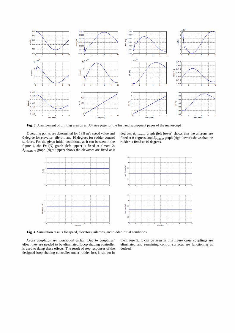
Fig. 3. Arrangement of printing area on an A4 size page for the first and subsequent pages of the manuscript
Operating points are determined for 18.9 m/s speed value and
0 degree for elevator, aileron, and 10 degrees for rudder control
surfaces. For the given initial conditions, as it can be seen in the
figure 4, the Fx (N) graph (left upper) is fixed at almost 2,
graph (right upper) shows the elevators are fixed at 0
degrees, graph (left lower) shows that the ailerons are
fixed at 0 degrees, and graph (right lower) shows that the
rudder is fixed at 10 degrees.
Fig. 4. Simulation results for speed, elevators, ailerons, and rudder initial conditions.
Cross couplings are mentioned earlier. Due to couplings’
effect they are needed to be eliminated. Loop shaping controller
is used to damp these effects. The result of step responses of the
designed loop shaping controller under rudder loss is shown in
the figure 5. It can be seen in this figure cross couplings are
eliminated and remaining control surfaces are functioning as
desired.
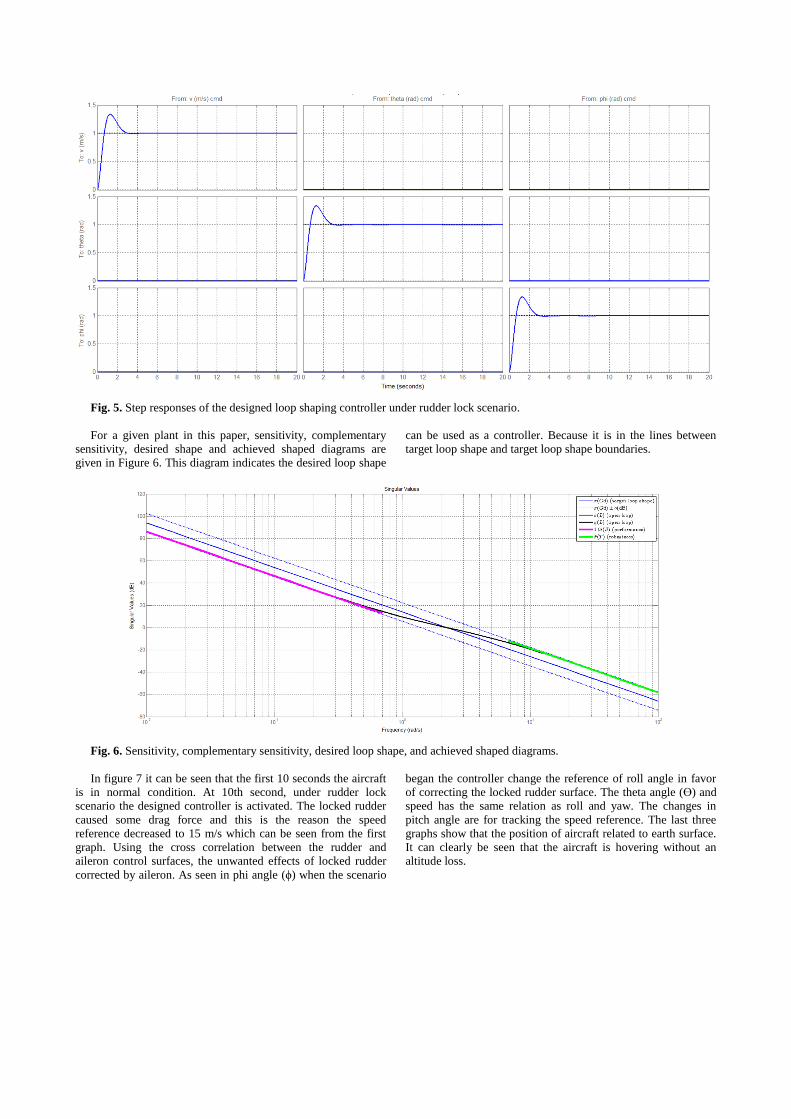
Fig. 5. Step responses of the designed loop shaping controller under rudder lock scenario.
For a given plant in this paper, sensitivity, complementary
sensitivity, desired shape and achieved shaped diagrams are
given in Figure 6. This diagram indicates the desired loop shape
can be used as a controller. Because it is in the lines between
target loop shape and target loop shape boundaries.
Fig. 6. Sensitivity, complementary sensitivity, desired loop shape, and achieved shaped diagrams.
In figure 7 it can be seen that the first 10 seconds the aircraft
is in normal condition. At 10th second, under rudder lock
scenario the designed controller is activated. The locked rudder
caused some drag force and this is the reason the speed
reference decreased to 15 m/s which can be seen from the first
graph. Using the cross correlation between the rudder and
aileron control surfaces, the unwanted effects of locked rudder
corrected by aileron. As seen in phi angle (ϕ) when the scenario
began the controller change the reference of roll angle in favor
of correcting the locked rudder surface. The theta angle (ϴ) and
speed has the same relation as roll and yaw. The changes in
pitch angle are for tracking the speed reference. The last three
graphs show that the position of aircraft related to earth surface.
It can clearly be seen that the aircraft is hovering without an
altitude loss.
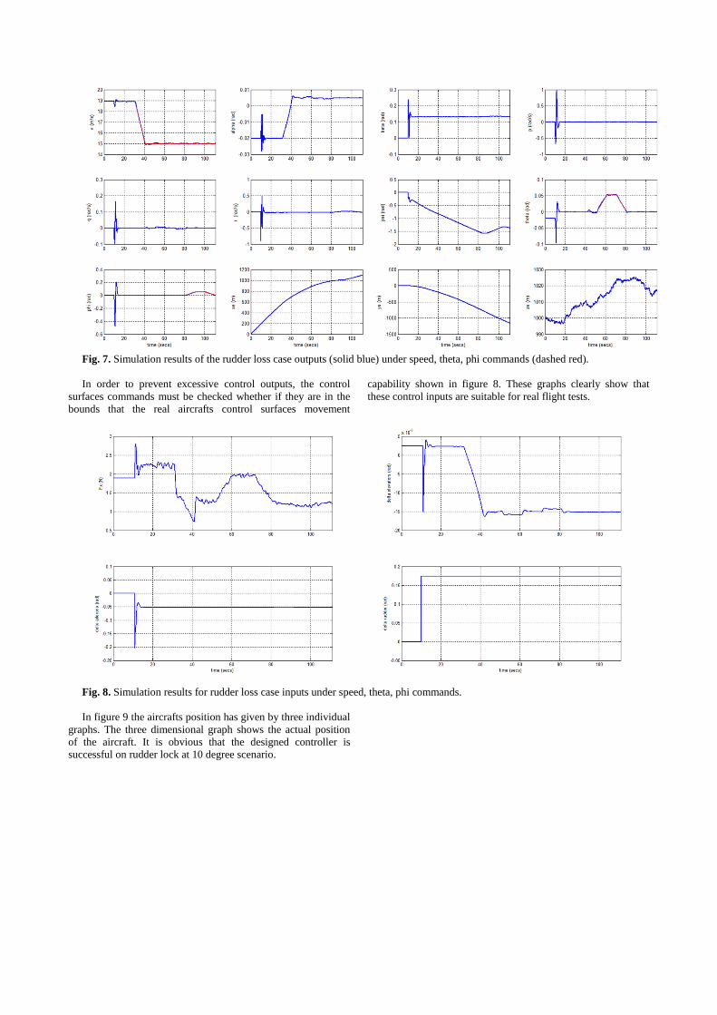
Fig. 7. Simulation results of the rudder loss case outputs (solid blue) under speed, theta, phi commands (dashed red).
In order to prevent excessive control outputs, the control
surfaces commands must be checked whether if they are in the
bounds that the real aircrafts control surfaces movement
capability shown in figure 8. These graphs clearly show that
these control inputs are suitable for real flight tests.
Fig. 8. Simulation results for rudder loss case inputs under speed, theta, phi commands.
In figure 9 the aircrafts position has given by three individual
graphs. The three dimensional graph shows the actual position
of the aircraft. It is obvious that the designed controller is
successful on rudder lock at 10 degree scenario.
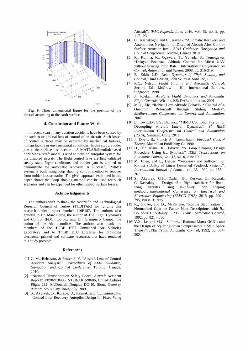
Fig. 9. Three dimensional figure for the position of the
aircraft according to the earth surface.
4. Conclusion and Future Work
In recent years, many aviation accidents have been caused by
the sudden or gradual loss of control of an aircraft. Such losses
of control surfaces may be occurred by mechanical failures,
human factors or environmental conditions. In this study, rudder
jam is the surface loss scenario. A MATLAB/Simulink based
nonlinear aircraft model is used to develop autopilot system for
the disabled aircraft. The flight control laws are first validated
steady state flight conditions and rudder jam is applied to
demonstrate the automatic recovery. A successful MIMO
system is built using loop shaping control method to recover
from rudder loss scenarios. The given approach explained in this
paper shows that loop shaping method can be used for such
scenarios and can be expanded for other control surface losses.
Acknowledgements
The authors wish to thank the Scientific and Technological
Research Council of Turkey (TUBITAK) for funding this
research under project number 116E187. The authors also
grateful to Dr. Marc Rauw, the author of The Flight Dynamics
and Control (FDC) toolbox and Dr. Giampiero Campa, the
author of the Airlib toolbox. The authors also thank the
members of the TOBB ETU Unmanned Air Vehicles
Laboratory and to TOBB ETU Libraries for providing
electronic, printed and software resources that have rendered
this study possible.
References
[1] C. M., Belcastro, & Foster, J. V. “Aircraft Loss of Control
Accident Analysis,” Proceedings of AIAA Guidance,
Navigation and Control Conference. Toronto, Canada,
2010.
[2] “National Transportation Safety Board, Aircraft Accident
Report”, PB90-910406, NTSB/ARR-90/06, United Airlines
Flight 232, McDonnell Douglas DC-10, Sioux Gateway
Airport, Sioux City, Iowa, July 1989.
[3] S., Akyurek, B., Kurkcu, U., Kaynak, and C., Kasnakoglu,
“Control Loss Recovery Autopilot Design for Fixed-Wing
Aircraft”, IFAC-PapersOnLine, 2016, vol. 49, no. 9, pp.
117-123.
[4] C., Kasnakoglu, and U., Kaynak, “Automatic Recovery and
Autonomous Navigation of Disabled Aircraft After Control
Surface Actuator Jam”, AIAA Guidance, Navigation and
Control Conference, Toronto, Canada 2010.
[5] R., Kojima, K., Ogawara, T., Yoneda, S., Tomoigawa,
“Delayed Feedback Altitude Control for Micro UAV
without Sensing Pitch Rate”, International Conference on
Control, Automation and Sytems, 2008, pp. 316-319.
[6] B., Etkin, L.D., Reid, Dynamics of Flight Stability and
Control, Third Edition, John Wiley & Sons Inc, 1996.
[7] R.C., Nelson, Flight Stability and Automatic Control,
Second Ed., McGraw – Hill International Editions,
Singapore, 1998.
[8] J., Roskam, Airplane Flight Dynamics and Automatic
Flight Controls, Wichita, KS: DARcorporation, 2001.
[9] M.O., Efe, “Robust Low Altitude Behaviour Control of a
Quadrotor Rotorcraft through Sliding Modes”,
Mediterranean Conference on Control and Automation,
2007.
[10] L., Keviczky, C.S., Bányász, “MIMO Controller Design for
Decoupling Aircraft Lateral Dynamics”, 9th IEEE
International Conference on Control and Automation
(ICCA), Santiago, Chile, 2011.
[11] J., Doyle, B., Francis A., Tannenbaum, Feedback Control
Theory, Macmillan Publishing Co 1990.
[12] D., McFarlane, K., Glover, “A Loop Shaping Design
Procedure Using Synthesis” IEEE Transactions on
Automatic Control, Vol. 37, No. 6, June 1992.
[13] M., Chen, and C., Desoer, “Necessary and Sufficient for
Robust Stability of Linear Disturbed Feedback Systems”,
International Journal of Control, vol. 35, 1992, pp. 255 –
267.
[14] S., Akyurek, G.S., Ozden, B., Kurkcu, U., Kaynak,
C., Kasnakoglu, “Design of a flight stabilizer for fixed-
wing aircrafts using H-infinity loop shaping
method”, International Conference on Electrical and
Electronics Engineering (ELECO 2015), 2015, pp. 790 –
795, Bursa, Turkey.
[15] K., Glover, and D., McFarlane, “Robust Stabilization of
Normalized Coprime Factor Plant Descriptions with
Bounded Uncertainty”, IEEE Trans. Automatic Control,
1992, pp. 821 – 830.
[16] V.X., Le, and M.G., Safonov, “Rational Matrx GCD’s and
the Design of Squaring-down Sompensators a State Space
Theory”, IEEE Trans. Automatic Control, 1992, pp. 384-
392.