autopilot - puget sound · pdf filefap-5002 control unit fap-5001/5011 (max. 6)* heading...
TRANSCRIPT

PRINTED IN JAPAN
AUTOPILOT
NAVpilot-500/511

Your Local Agent/DealerYour Local Agent/Dealer
9-52 Ashihara-cho,9-52 Ashihara-cho,Nishinomiya, JapanNishinomiya, Japan
Telephone :Telephone : 0798-65-21110798-65-2111faxfax 0798-65-42000798-65-4200::
FIRST EDITION :FIRST EDITION : APR.APR. 20032003Printed in JapanPrinted in JapanAll rights reserved.All rights reserved.DD :: DEC.DEC. 15,200315,2003
PUB.No.PUB.No. IME-72500-DIME-72500-D*00014698802**00014698802**00014698802**00014698802*(( HIMAHIMA )) NAVPILOT-500NAVPILOT-500
* 0 0 0 1 4 6 9 8 8 0 2 ** 0 0 0 1 4 6 9 8 8 0 2 *
*IME72500D00**IME72500D00**IME72500D00**IME72500D00*
* I M E 7 2 5 0 0 D 0 0 ** I M E 7 2 5 0 0 D 0 0 *

i
WARNINGTurn off the power at the switchboardbefore beginning the installation.
Fire or electrical shock can result if thepower is left on.
Use the specified power cable.
Use of other power cable may result infire.
CAUTION
Observe the following compass safedistances to prevent interference to amagnetic compass:
Controlunit
Standard Steeringcompass compass
0.45 m 0.3 m
Confirm that the power supply voltageis compatible with the voltage rating of the equipment.
Connection to the wrong power supplycan cause fire or equipment damage.
Processorunit 0.35 m 0.3 m
SAFETY INSTRUCTIONS
Remotecontrollers 0.3 m 0.3 m
Confirm that no one is near the rudderwhen bleeding air from oil cylinder.
The rudder may move unexpectedly,possibly causing bodily injury.
FAP-5001
FAP-5011 0.3 m 0.3 m

ii
TABLE OF CONTENTS
SYSTEM CONFIGURATION................................................................................ iii
EQUIPMENT LISTS ............................................................................................. iv
1. INSTALLATION OF UNITS ........................................................................... 1-1 1.1 Control Unit FAP-5001/5011...................................................................................... 1-1 1.2 Processor Unit FAP-5002.......................................................................................... 1-4 1.3 Rudder Reference Unit FAP-6111.............................................................................. 1-5 1.4 Remote Controllers (option) ...................................................................................... 1-6
2. WIRING.......................................................................................................... 2-1 2.1 Wiring System........................................................................................................... 2-1 2.2 Processor Unit........................................................................................................... 2-2 2.3 Control Unit ............................................................................................................... 2-7 2.4 Remote Controllers (option) ...................................................................................... 2-8 2.5 Connection of Instruments FI-30 ..............................................................................2-11 2.6 Input/Output Sentences............................................................................................2-12
3. ADJUSTMENTS............................................................................................ 3-1 3.1 How to Access the Installation Menu ......................................................................... 3-1 3.2 DOCKSIDE SETUP Menu......................................................................................... 3-2 3.3 SEA TRIAL Menu ...................................................................................................... 3-9 3.4 DISPLAY SETUP Menu............................................................................................3-14 3.5 DATA CALIBRATION Menu ......................................................................................3-16 3.6 Other Settings ..........................................................................................................3-17
PACKING LISTS
OUTLINE DRAWINGS
INTERCONNECTION DIAGRAM

iii
SYSTEM CONFIGURATION
12-24 VDC
Processor UnitFAP-5002
Control UnitFAP-5001/5011 (Max. 6)*
Heading sensorPG-500
Rudder Reference UnitFAP-6111
Remote Controller
Distributor FAP-6800
Remote Controller
Remote Controller
Reversible pump orElectromagnetic valve unit
PC
External buzzer
Navigator(NMEA0183)
RD-30 (Max. 3)(NMEA0183)
Clutch
Remote Controller
Remote controlerDial type: FAP-5551, FAP-5552Button type: FAP6211, FAP-6212Lever type: FAP-6221, 6222Dodge type: FAP-6231, 6232
: Standard: Option: User supply
Ship's steering system
*: Any combination of FAP-5001 and 5011 is available.

iv
EQUIPMENT LISTS Standard supply for Navpilot-500
Name Type Code No. Qty Remarks Control Unit FAP-5001-E - 1 Processor Unit FAP-5002 - 1
FAP-6111-100 - w/10 m cable Rudder Reference Unit FAP-6111-200 -
1 w/20 m cable
CP64-02200 - 1 set
For Control Unit, MJ-A7SPF cable and CP64-02201
CP64-02210 - 1 set
For Processor Unit, MJ-A7SPF cable and CP64-02211
Installation Materials
CP64-01700 009-012-450 1 set For Rudder reference Unit Spare Parts SP64-01401 - 1 set For Processor Unit, fuse Accessories FP64-01001 - 1 set For Control Unit, terminator Standard supply for Navpilot-511
Name Type Code No. Qty Remarks Control Unit FAP-5011-E - 1 Processor Unit FAP-5002 - 1
FAP-6111-100 - w/10 m cable Rudder Reference Unit FAP-6111-200 -
1 w/20 m cable
CP64-02400 009-000-580 1 setFor control unit, MJ-A7SPF cable and CP64-02401
CP64-02210 009-000-620 1 set For Processor unit Installation Materials
CP64-01700 009-012-450 1 set For Rudder reference unit Spare Parts SP64-01401 009-000-610 1 set For Processor unit, fuse Accessories FP64-01001 009-000-600 1 set For Control unit, terminator
v
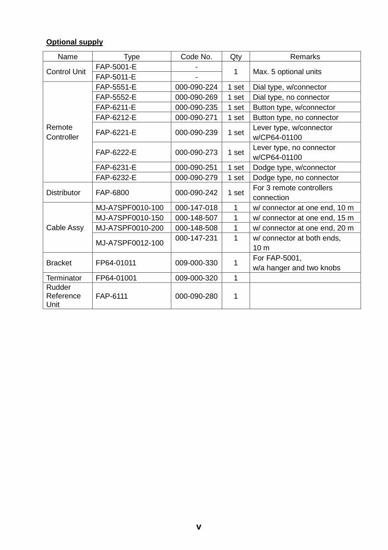
Optional supply
Name Type Code No. Qty Remarks FAP-5001-E - Control Unit FAP-5011-E -
1 Max. 5 optional units
FAP-5551-E 000-090-224 1 set Dial type, w/connector FAP-5552-E 000-090-269 1 set Dial type, no connector FAP-6211-E 000-090-235 1 set Button type, w/connector FAP-6212-E 000-090-271 1 set Button type, no connector
FAP-6221-E 000-090-239 1 set Lever type, w/connector w/CP64-01100
FAP-6222-E 000-090-273 1 set Lever type, no connector w/CP64-01100
FAP-6231-E 000-090-251 1 set Dodge type, w/connector
Remote Controller
FAP-6232-E 000-090-279 1 set Dodge type, no connector
Distributor FAP-6800 000-090-242 1 set For 3 remote controllers connection
MJ-A7SPF0010-100 000-147-018 1 w/ connector at one end, 10 m MJ-A7SPF0010-150 000-148-507 1 w/ connector at one end, 15 m MJ-A7SPF0010-200 000-148-508 1 w/ connector at one end, 20 m Cable Assy
MJ-A7SPF0012-100 000-147-231 1 w/ connector at both ends, 10 m
Bracket FP64-01011 009-000-330 1 For FAP-5001, w/a hanger and two knobs
Terminator FP64-01001 009-000-320 1 Rudder Reference Unit
FAP-6111 000-090-280 1

vi
This page is intentionally left blank.

1-1
1. INSTALLATION OF UNITS
1.1 Control Unit FAP-5001/5011 The control unit can be flush mounted in a console panel. For the FAP-5001, the desktop mounting is also available using the optional bracket kit.
FAP-5001 FAP-5011
Control unit
When selecting a mounting location for the control unit, keep the following in mind. • The mounting location should be well ventilated.
• Mount the unit where shock and vibration are minimal.
• Use the supplied display hard cover when the system is not in use.
• Do not mount the display unit under “Plexiglas” or any other type of shielding which could trap heat and moisture or magnify sunlight energy onto the surface of the display.
• For maintenance and checking purposes, leave sufficient space at the sides and rear of the unit and leave slack in cables.
• A magnetic compass will be affected if the control unit is placed too close to the magnetic compass. Observe the compass safe distances to prevent disturbance to the magnetic compass. FAP-5001: standard: 0.45 m, steering: 0.3 m. FAP-5011: standard: 0.3 m, steering: 0.3 m

1. INSTALLATION OF UNITS
1-2
1.1.1 Flush mounting Follow the procedure below to mount the control unit in a console panel. 1. Prepare a cutout in the mounting location using the template sheet supplied. 2. Screw four threaded rods (supplied) into holes on the back of the control unit tightly. 3. Pass four threaded rods screwed at step 2 through holes made at step 1, flat washers,
spring washers and wing screws (supplied). 4. Screw four thumbscrews tightly.
Flat washer
Spring washer
Wing screw
Wing screw
Flush mounting of control unit

1. INSTALLATION OF UNITS
1-3
1.1.2 Desktop mounting (FAP-5001 only) Use the optional brackets to mount the control unit FAP-5001 on a desktop or the overhead. Name: Bracket Type: FP64-01011 Code No.: 009-000-330
Name Type Code No. Qty Hanger 64-024-1502 100-305-820 1 Knob 02-139-1032 100-298-472 2 Bracket 03-153-1155 100-288-890 2 Pan head screw M4x10 000-881-964 4 Tapping screw 5x20 000-802-081 4
1. Fix the hanger to the mounting location with four tapping screws (supplied with option). 2. Attach two brackets to the back of the control unit with four pan head screws (supplied
with option). 3. Screw knob bolts in brackets, set unit to hanger, and tighten knob bolts. 4. Attach hard cover to protect the LCD.
Control unit, desktop mounting

1. INSTALLATION OF UNITS
1-4
1.2 Processor Unit FAP-5002 This unit can be mounted on a desktop or on a bulkhead. Select a mounting location considering the points below. • Locate the unit out of direct sunlight and water splash.
• Select a location where temperature and humidity are moderate and stable.
• Consider the length of the cable connected between the processor unit and other units.
• Locate the unit where its cover can be removed and cabling easily accessed.
• For mounting on a bulkhead, be sure the mounting location is strong enough to support the unit under the pitching and rolling normally encountered on the vessel.
• Leave sufficient space around the unit for maintenance and servicing. Recommended maintenance space appears in the outline drawing at the back of this manual.
• A magnetic compass will be affected if the processor unit is placed too close to the magnetic compass. Observe the compass safe distances to prevent disturbance to the magnetic compass: standard: 0.35 m, steering: 0.3 m.
1. Unfasten five pan head screws to remove the cover. 2. Mount the unit as follows:
Tabletop: Fasten with four tapping screws. Bulkhead mounting: Screw in four tapping screws in the mounting location, leaving 5 mm protruding. Set the processor unit to the screws and tighten screws.
3. Reattach the cover.
Processor unit

1. INSTALLATION OF UNITS
1-5
1.3 Rudder Reference Unit FAP-6111 • Leave sufficient space around all moving parts.
• The unit must be coupled to the rudder as shown below, where the following conditions are satisfied:
Use four tapping screws and flat washers (supplied) to fasten the rudder reference unit with gasket (supplied). 350 mm < Y2 < 600 mm X1 = X2 Y1 = Y2
X1 X2
Y1
Y2
90
Top view
Mounting the rudder reference unit
The FAP-6101 may be substituted (for FAP-300/330) instead of the FAP-6111.

1. INSTALLATION OF UNITS
1-6
Relationship between Reversing Pump Flow Rate and Steering Cylinder Capacity
The table below shows a rough guideline to determine the proper Reversing Pump Flow Rate to match with the Hydraulic Steering Cylinder capacity. Your experience with specific boat designs may cause you to select a pump/cylinder relationship outside of the range of these guidelines.
Hardover to Hardover is 70º. Hardover to Hardover is 90º.
1.0 cu. in./sec. pump 5.85 to 17.5 cu. in. 7.5 to 22.5 cu. in.
1.6 cu. in./sec. pump 9.36 to 28.0 cu. in. 12.0 to 36.0 cu. in. • If the Hydraulic Cylinder capacity is much smaller than the recommended values in the
table, the rudder turning speed maybe too fast for the pilot to deliver proper performance. The rudder deadband will decrease and the Navpilot System may not apply enough voltage for the pump motor to start because the applied “Duty Cycle” will be too low.
• If the Hydraulic Cylinder capacity is much larger than the recommended values in the table, the rudder turning speed may be too slow to allow the Navpilot System to control the boat effectively.
1.4 Remote Controllers (option) Two remote controllers may be connected to the processor unit FAP-5002. To connect three or four remote controllers, the optional distributor FAP-6800 is required. Note 1: The distributor FAP-6800 enables connection of three NFU (Non-Follow Up) type remote controllers (button and lever) to the processor unit. Note 2: Keep the remote controller out of water splash. Dial type remote controller FAP-5551/5552
FAP-5551, bulkhead mounting

1. INSTALLATION OF UNITS
1-7
Dial type remote controller FAP-5551/5552 can also be mounted on the bulkhead by using the optional hanger OP64-2 (Code No.: 009-004-030).
Mounting the hunger for FAP-5551/5552
For handheld operation in the opposite direction, reverse the switch and dial blocks so that the dial is readable. To do this, loosen the four screws shown below. Note that the switch and dial blocks are inserted into the controller body with O-rings. Be careful not to damage them.
Reversing the switch and dial blocks

1. INSTALLATION OF UNITS
1-8
Button type remote controller FAP-6211/6222
FAP-6211, bulkhead mounting
Lever type remote controller FAP-6221/6222
Allow sufficient space around the unit for maintenance.
FAP-6221, bulkhead mounting

1. INSTALLATION OF UNITS
1-9
To mount the FAP-6221/6212 in a panel, the optional flush mount kit OP64-4 (Code No.: 009-005-790) or OP64-5 (Code No.: 009-005-800) is required.
Contents of OP64-4
Name Type Code No. Qty
Panel OP64-4 009-006-370 1
O-ring 64-015-4524 009-006-180 1
Hex. nut M4 000-863-106 4
Flat washer M4 000-864-256 4
Spring washer M4 000-868-786 4
Contents of OP64-5
Name Type Code No. Qty
Fixing plate OP64-5 009-006-200 1
O-ring 64-015-4524 100-145-111 1
Hex. nut M4 000-863-106 4
Spring washer M4 000-864-256 4
Hex. bolt M4x35 000-868-786 4
FAP-6221, flush mounting (OP64-4)

1. INSTALLATION OF UNITS
1-10
FAP-6221, flush mounting (OP64-5)
Distributor FAP-6800
For thin walls, use nuts, bolts and washers (all are local supplied) instead of wood screws.
FAP-6800, desktop mounting

2-1
2. WIRING
2.1 Wiring System All units are connected to the processor unit. The cables should be separated as far as possible from cables carrying radio frequency or pulsed signals. At least one meter separation is recommended.
Wiring (ex. Navpilot-500)

2. WIRING
2-2
2.2 Processor Unit All cables run into the processor unit from the cable entrance and are connected to the terminal board inside. 2.2.1 How to fix cables to the clamp Cables are not location-specific so you may fix them on the cable clamp in any order. 1. Unfasten five pan head screws to remove the cover. 2. Unscrew five pan head screws to dismount the clamp stopper.
Processor unit, clamp stopper
3. Twist cable cores, and then insert them into the cable block as appropriate. 4. For NMEA cable, wind vinyl tape (local supply) around cable cores. 5. Fasten three cable ties to attach a cable to the appropriate leg of the processor unit as
below.
Clamp leg
Cable
Cable ties
Braided shield(If your cable doesn't have braided shield, wind the copper tape around alminum foil.)
Drain wire
Vinyl tape
Cable block
How to fix the cable to clamp leg
2. WIRING
2-3
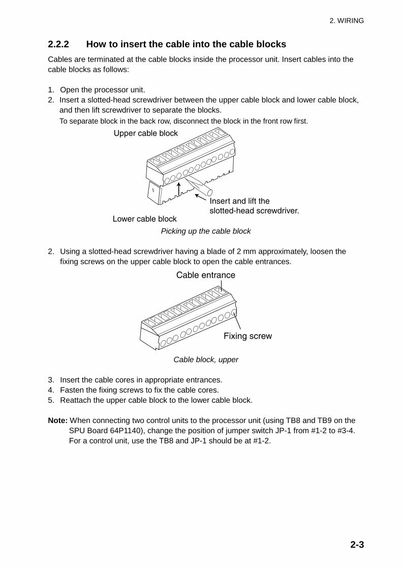
2.2.2 How to insert the cable into the cable blocks Cables are terminated at the cable blocks inside the processor unit. Insert cables into the cable blocks as follows: 1. Open the processor unit. 2. Insert a slotted-head screwdriver between the upper cable block and lower cable block,
and then lift screwdriver to separate the blocks. To separate block in the back row, disconnect the block in the front row first.
Insert and lift the slotted-head screwdriver.
Lower cable block
Upper cable block
Picking up the cable block
2. Using a slotted-head screwdriver having a blade of 2 mm approximately, loosen the
fixing screws on the upper cable block to open the cable entrances.
Fixing screw
Cable entrance
Cable block, upper
3. Insert the cable cores in appropriate entrances. 4. Fasten the fixing screws to fix the cable cores. 5. Reattach the upper cable block to the lower cable block. Note: When connecting two control units to the processor unit (using TB8 and TB9 on the
SPU Board 64P1140), change the position of jumper switch JP-1 from #1-2 to #3-4. For a control unit, use the TB8 and JP-1 should be at #1-2.

2. WIRING
2-4
Control unit
Remote controller
Rudder reference unit
HeadingSensor
(PG-500)
NMEAIn/Out
NMEAOut
NMEAIn
RS232C
Ext. Buzzer
Ship'smainsMotor
PWR+,B/Clutch
JP-1#1-2#3-4
TB9 TB10
1 2 3 4 5
#1-2#3-4 JP-2
Processor unit, inside view
2.2.3 Power and Motor cable For ship’s mains cable and motor line cable, use the recommended shielded cable referring to the table shown below.
Motor Voltage 12 VDC 24 VDC Cable length Section of core
(mm²) AWG Section of core (mm²) AWG
3 m or less 2.5 12 2.5 12 6 m or less 4 10 2.5 12 10 m or less 6 8 4 10 16 m or less 10 6 6 8

2. WIRING
2-5
MOTOR A MOTOR B GND POWER + POWER -SOL A SOL B
TB2 TB1 Reversible pump
MOTOR A MOTOR B GND POWER + POWER -SOL A SOL B
TB2 TB1
TB3
PWR+ SHLDB/C
SHLDBUZZ
Hydraulic linear drive
MOTOR A MOTOR B GND POWER + POWER -SOL A SOL B
TB2 TB1 SolenoidSolenoid
GND.
Solenoid
Solenoid valve
Connecing a reversible pump
Connecing a hydraulic linear drive
Connecing a solenoid valve
Connecting motors

2. WIRING
2-6
2.2.4 Connection of Terflex ® linear sensor When connecting the Teleflex ® linear sensor AR4102/AR4302 instead of the FAP-6111, do the following modification. 1. Cut the black jumper at the back of the AR4102/4302.
DO NOT cut the red jumper. 2. Make the cable connection as shown below. 3. Change the position of jumper switch JP-2 from #3-4 to #1-2, referring to the illustration
shown on page 2-4. 4. Set SELECT RRU to “LINEAR SENSOR” on the DOCKSIDE SETUP menu. For further
details, see chapter 3.
12345
SPU Board(64P1140)
TB13
Linear sensorAR4102
or AR4302
REDWHT
BLK
BARE
Processor unit
Connection of linear sensor AR4102/AR4302

2. WIRING
2-7
2.3 Control Unit A maximum of six control units may be connected. The processor unit has two ports for connection of two main control units, and two control units may be connected in series to each main control unit. Use the cable MJ-A7SPF0010-100 (10 m, supplied), MJ-A7SPF0015 (15 m, option) or MJ-A7SPF0010-200 (20 m, option) to connect the control unit and processor unit, MJ-A7SPF0012-100 (10 m, option) to connect two control units. Note 1: Ports are not location-specific so you may use them at the back of the control unit
whichever. Note 2: Attach the terminator MJ-A7SPF0011 to the port not used on the last control unit in
the series, using an unused port. Note 3: When a control unit is connected, use the TB8. Note 4: Total length of cables on a series should be within 30 m.
Processor unit
Control unit
MJ-A7SPF0010-100/150/200
MJ-A7SPF0010-100/150/200
MJ-A7SPF0012-100MJ-A7SPF0012-100
MJ-A7SPF0012-100MJ-A7SPF0012-100
Connection of six control units

2. WIRING
2-8
2.4 Remote Controllers (option) The processor unit has two ports for connection of two remote controllers. The Distributor FAP-6800 enables connection of three NFU (Non Follow-Up) type remote controllers to the processor unit. Note 1: Connect remote controllers having connectors to the distributor FAP-6800. Note 2: After the connection of remote controller, set the remote controller type on the
SYSTEM SETUP menu. (See page 3-15.)
Remote controllers with connector Remote controller without connector FAP-5551 (dial), FAP-6211 (button), FAP-6221 (lever), FAP-6231 (dodge)
FAP-5552 (dial), FAP-6212 (button), FAP-6222 (lever), FAP-6232
2.4.1 Example remote controller connections No distributor
Any two remote controllers can be connected.
FAP-5552, FAP-6212, or FAP-6222
Processor unitFAP-5552, FAP-6212, or FAP-6222
Connection of remote controllers without distributor
Dial type remote controller
For dial-type remote controller, the distributor cannot be used.
FAP-5552 (dial)
Processor unit
FAP-5552 (dial)
Connection of dial type

2. WIRING
2-9
Button or lever remote controller with distributor
Maximum six button or lever remote controllers can be connected.
FAP-6211 (button)/6221 (lever)
Processor unit
FAP-6211 (button)/6221 (lever)
FAP-6211 (button)/6221 (lever)
FAP-6211 (button)/6221 (lever)
FAP-6211 (button)/6221 (lever)
FAP-6211 (button)/6221 (lever) Connection of button or lever remote controllers
Dodge remote controller with distributor
Maximum six dodge type remote controllers can be connected.
FAP-6231 (dodge type)
Processor unit
FAP-6231 (dodge type)
FAP-6231 (dodge type)
FAP-6231 (dodge type)
FAP-6231 (dodge type)
FAP-6231 (dodge type) Connection of six dodge remote controllers

2. WIRING
2-10
2.4.2 Prohibited remote controller connections The following remote controller connections are not possible. Wrong connection 1
Different types of remote controllers cannot be connected.
FAP-6211 (button)
Processor unit
FAP-6221 (lever)
FAP-6231 (dodge)
FAP-6211 (button)
FAP-6221 (lever)
FAP-6231 (dodge)
Wrong connection 1
Wrong connection 2
Only one dial remote controller can be connected.
FAP-5551 (dial)
Processor unit
FAP-5551 (dial)
FAP-5551 (dial)
FAP-5551 (dial)
Wrong connection 2

2. WIRING
2-11
Wrong connection 3
Multiple distributors cannot be connected.
Processor unit
Wrong connection 3
2.5 Connection of Instruments FI-30 The FI-30 series has various sensors, such as speed, depth, wind, etc. These sensors can be connected to the NAVpilot-500/511 via the FI-30 server, and the NAVpilot-500/511 can show data from them on its graphic display. To connect the NAVpilot-500 to the FI-30 server, see the connection diagram shown below.
OUT A 1OUT B 2
IN A 3IN B 4
F.G.
1 +12V2 0 V3 OUTPUT A4 OUTPUT B
10 INPUT A11 INPUT B
+ -
NMEA
NMEA GPS
Processor unitFAP-5002
FI-30 Server
NMEA IN/OUT
IN A 3IN B 4
OUT A 3OUT B 4
1 +12V2 0 V3 OUTPUT A4 OUTPUT B
10 INPUT A11 INPUT B
+ -
NMEA
NMEA GPS
Processor unitFAP-5002 FI-30 Server
NMEA OUT
NMEA IN
Connection using the NMEA IN and NMEA OUT ports on FAP-5002
Connection using the NMEA IN/OUT ports on FAP-5002
TB7
TB5
TB6

2. WIRING
2-12
2.6 Input/Output Sentences
Port in the processor
unit
Input/ Output Data Sentences (priority) Remarks
Input Heading HDT (True), HDG, HDM (Magnetic)
NMEA0183 Ver. 1.5/2.0/3.0, 200 ms interval
SENSOR
Output FURUNO specified Own ship position GGA>RMC>RMA>GLL
Ship’s speed (SOG) VTG>RMC>RMA (STW) VHW
Waypoint location RMB>WPL Bearing and distance to waypoint
RMB>BWC>BWR
Course RMC>RMA>VTG Date RMC>ZDA Waypoint arrival alarm AAM>RMB Cross-track error APB>XTE>RMB Heading HDT>HDG>HDM Depth DPT>DBT Water temperature MTW
Input/Output
Wind direction/speed VPW>MWD>MWV Auto pilot mode Rudder angle Bearing error
NMEA IN/OUT
Output only
Heading
FURUNO specified
NMEA0183 Ver. 1.5/2.0/3.0
NMEA OUT Output Same as output for “NMEA IN/OUT”
Ship’s speed (SOG) VTG>RMC>RMA (STW) VHW
Depth DPT>DBT Water temperature MTW Own ship position GGA>RMC>RMA>GLL
NMEA IN Input*
Wind direction/speed VPW>MWD>MWV
NMEA0183 Ver. 1.5/2.0/3.0
Same as input for “NMEA IN/OUT” Input*
Programs RS232 IN/OUT
Output Outputs data same as “NMEA IN/OUT”
*NMEA IN and RS232 IN cannot be used at the same time.

3-1
3. ADJUSTMENTS
3.1 How to Access the Installation Menu Set up the equipment through the installation menu. To access the installation menu, do the followings: 1. Turn the power on at the control unit. 2. Press the [STBY] ([STBY/POWER] for Navpilot-511) key to go to the STBY mode. 3. Press the [MENU] ([TURN/MENU for Navpilot-511]) key while pressing the [STBY]
([STBY/POWER]) key. 4. Release the above keys when the INSTALLATION menu appears.
INSTALLATION MENU
DOCKSIDE SETUPSEA TRIALDISPLAY SETUPDATA CALIBRATIONPARAMETER SETUPSYSTEM SETUPALARM MENU
ADJUST RUD REF. UNIT: NORUDDER TEST: NOSET CENTER RUDDER POS: NOAUTO TUNING: NOCOMPASS CALIBRATION: NO
"DONE" is shown when setting is completed.
DOCKSIDE SETUPSEA TRIALDISPLAY SETUP
DATA CALIBRATIONMESSAGEPARAMETER SETUPSYSTEM SETUPALARM SETUPCONTRAST/BRILLIANCE
ADJUST RUD REF. UNIT: NORUDDER TEST: NOSET CENTER RUDDER POS: NOAUTO TUNING: NOCOMPASS CALIBRATION: NO
Navpilot-500 Navpilot-511
INSTALLATION MENU
Installation menu
The installation should be done in the order in which the items of the installation menu are listed.

3. ADJUSTMENTS
3-2
3.2 DOCKSIDE SETUP Menu The DOCKSIDE SETUP menu provides for initial setup of the equipment. 1. Open the INSTALLATION menu. 2. Rotate the course control knob to select “DOCKSIDE SETUP”. 3. Press the course control knob to show the DOCKSIDE SETUP menu.
DRIVE UNIT: SOLENOIDSELECT RRU: FURUNO RRUAIR BLEEDING: NOBOAT TYPE: PLANINGBOAT LENGTH: 35 ft (10.7 m)MAXIMUM SPEED: 30 kt (55.6 km/h)ADJUST RUDDER REF. UNITAUTO RUDDER LIMIT: 10MANUAL RUDDER LIMIT: 20RUDDER TEST: NORATE OF TURN: 3 /sCOMPASS TYPE: PG-500COMPASS BAUD RATE: 4800SET CENTER RUDDER POSITION
PUSH MENU KEY TO RETURNTO PREVIOUS MENU.
DRIVE UNIT: SOLENOIDSELECT RRU: FURUNO RRUAIR BLEEDING: NOBOAT TYPE: PLANINGBOAT LENGTH: 35 ft (10.7 m)MAX. SPD.: 30 kt (55.6 km/h)ADJUST RUDDER REF. UNITAUTO RUDDER LIMIT: 10MANUAL RUDDER LIMIT: 20
RUDDER TEST: NORATE OF TURN: 3 /sCOMPASS TYPE: PG-500COMPASS BAUD RATE: 4800SET CENTER RUD. POS.
PUSH MENU KEY TO RETURNTO PREVIOUS MENU.
Navpilot-500 Navpilot-511
Dockside setup menu
3.2.1 Selecting your drive unit At the first of all, the drive type of your boat should be selected among from REVERSIBLE 24V, REVERSIBLE 12V and SOLENOID. 1. Open the DOCKSIDE SETUP menu. 2. Rotate the course control knob to select “DRIVE UNIT.” 3. Press the course control knob to show the drive unit options window.
REVERSIBLE 12VSOLENOID
REVERSIBLE 24V
Drive unit options window
4. Rotate the course control knob to select REVERSIBLE 12V, REVERSIBLE 24V or SOLENOID depending on your boat.
5. Press the course control knob to close the window.

3. ADJUSTMENTS
3-3
3.2.2 Selecting the type of rudder reference unit Select the type of your rudder reference unit at here. 1. Rotate the course control knob to select “SELECT RRU”, and then press the course
control knob. The select RRU options window appears.
LINEAR SENSORFURUNO RRU
Select RRU options window
2. Rotate the course control knob to select FURUNO RRU or LINEAR SENSOR. FURUNO RRU: The rudder reference unit FAP-6111 is connected. LINEAR SENSOR: The Teleflex® linear sensor AR4102 or AR4302 is connected.
3. Press the course control knob to close the window. When selecting LINEAR SENSOR, change the JP2 position certainly referring to paragraph 2.2.4.
3.2.3 Bleeding air in the oil cylinder If necessary, bleed air from the oil cylinder by moving the rudder automatically or manually.
WARNINGConfirm that no one is near the rudderwhen bleeding air from oil cylinder.
The rudder may move unexpectedly,possibly causing bodily injury.
1. Rotate the course control knob to select “AIR BLEEDING”, and then press the course
control knob to show the air bleeding options window.
USE ARROW KEYSUSE RRU
NOUSE KEYSUSE RRU
NO
Navpilot-500 Navpilot-511 Air bleeding options window
2. Rotate the course control knob to select USE ARROW (◄►) KEYS or USE RRU as appropriate.
3. Press the course control knob to show the rudder indicator.
AIR BLEEDING
40 20 10 5 5 10 20 40
0
PUSH ARROW KEYS TO ENABLEPUMPSET.PUSH MENU KEY WHEN DONE.
AIR BLEEDING
40 20 10 5 5 10 20 40
0
TURN RRU ARM TO ENABLEPUMPSET.PUSH MENU KEY WHEN DONE.
USE ARROW KEYS USE RRU Rudder indicators (ex. Navpilot-500)
3. ADJUSTMENTS
3-4
When selecting “USE ARROW (◄►) KEYS”
a) Press the [PORT] (or [STBD]) key until the indicator is completely filled (in black). b) Remove the appropriate rubber cap of the cylinder to bleed air. c) Press the [STBD] ([PORT]) key until the indicator is completely filled (in black). d) Remove the appropriate rubber cap of the cylinder to bleed air. e) Repeat steps a) through d) to bleed air completely. f) Press the [MENU] ([TURN/MENU]) key twice to finish.
When selecting “USING RRU”
a) Remove the rod from the rudder reference unit slowly, and then set the arm of the rudder reference unit to 0 point (notch of the unit).
b) Move the arm of the rudder reference unit to port more than 10 degrees. The rudder moves to port direction.
c) Repeat steps a) and b) to bleed air from the oil cylinder for starboard. d) Press the [MENU] ([TURN/MENU]) key twice to finish.
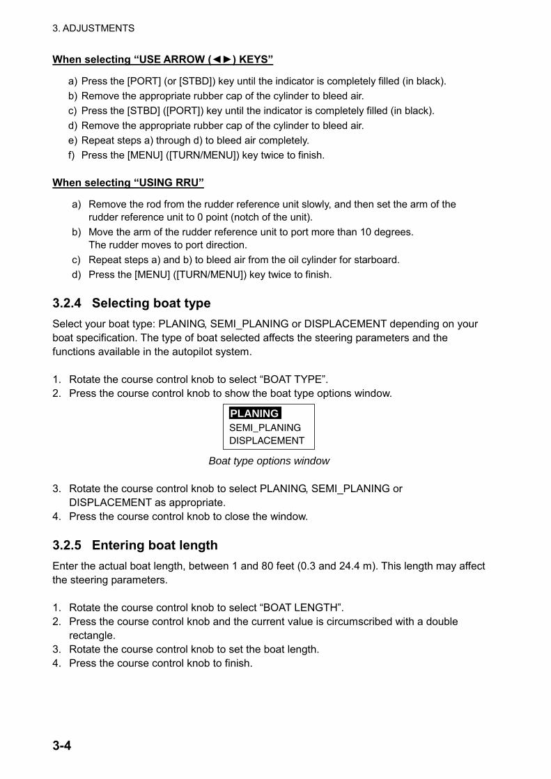
3.2.4 Selecting boat type Select your boat type: PLANING, SEMI_PLANING or DISPLACEMENT depending on your boat specification. The type of boat selected affects the steering parameters and the functions available in the autopilot system. 1. Rotate the course control knob to select “BOAT TYPE”. 2. Press the course control knob to show the boat type options window.
SEMI_PLANINGDISPLACEMENT
PLANING
Boat type options window
3. Rotate the course control knob to select PLANING, SEMI_PLANING or
DISPLACEMENT as appropriate. 4. Press the course control knob to close the window. 3.2.5 Entering boat length Enter the actual boat length, between 1 and 80 feet (0.3 and 24.4 m). This length may affect the steering parameters. 1. Rotate the course control knob to select “BOAT LENGTH”. 2. Press the course control knob and the current value is circumscribed with a double
rectangle. 3. Rotate the course control knob to set the boat length. 4. Press the course control knob to finish.

3. ADJUSTMENTS
3-5
3.2.6 Entering maximum speed Enter the maximum speed of your boat, between 1 and 99 kt (1.9 and 183.3 km/h). The speed entered affects the steering parameters. 1. Rotate the course control knob to select “MAXIMUM SPEED (MAX. SPD. For
Navpilot-511)” from the DOCKSIDE SETUP menu. 2. Press the course control knob and the current value is circumscribed with a double
rectangle. 3. Rotate the course control knob to set maximum speed. 4. Press the course control knob to finish. 3.2.7 Adjusting rudder reference unit Adjust the rudder angle indication as follows: 1. Rotate the course control knob to select “ADJUST RUDDER REF. UNIT.” 2. Press the course control knob to show the ADJUST RUDDER REF. UNIT menu.
ADJUST RUDDER REF. UNIT
RUDDER ANGLE: PORT 0PORT: 10STBD: 10
MANUALLY TURN HELMHARD-OVER TO PORTAND SET DEGREE VALUE.REPEAT FOR STARBOARD.PUSH MENU KEY WHEN FINISHED.
40 20 10 0 0 10 20 40 Adjust RRU menu (Ex. Navpilot-500)
3. Steer the helm to port direction fully. The current degree of the rudder reference unit arm is shown at the top of the menu.
4. Rotate the course control knob to select “PORT”. 5. Press the course control knob and the “10” for PORT is circumscribed with a double
rectangle. 6. Rotate the course control knob to set your boat’s maximum rudder angles referring to
the specification. 7. Press the course control knob. 8. Steer the helm to starboard direction fully.
The current degree of the rudder reference unit arm is shown at the top of the menu. 9. Rotate the course control knob to select “STBD”. 10. Press the course control knob and the “10” for STBD is circumscribed with a double
rectangle. 11. Rotate the course control knob to your boat’s maximum rudder angles referring to the
specification, and then press the course control knob. 12. Press the [MENU] ([TURN/MENU]) key to close the ADJUST RRU menu. While adjusting the rudder angle, the message “ADJUSTING RRU- PLEASE WAIT” appears on the other control units connected.

3. ADJUSTMENTS
3-6
3.2.8 Setting rudder auto movement limit AUTO RUDDER LIMIT determines the maximum rudder movement in degrees from the mid position in the AUTO or NAV mode. 1. Rotate the course control knob to select “AUTO RUDDER LIMIT”. 2. Press the course control knob and the current value is circumscribed with a double
rectangle. 3. Rotate the course control knob to set the rudder limit desired. (Setting range: 1 to 45°) 4. Press the course control knob. 3.2.9 Setting manual rudder movement limit In the REM (remote) or DODGE mode, usually a wide range of rudder angles are used, and therefore a larger number should be entered. However, the setting must not exceed the rudder limit angle which is inherent to your boat. 1. Rotate the course control knob to select “MANUAL RUDDER LIMIT”. 2. Press the course control knob and the current value is circumscribed with a double
rectangle. 3. Rotate the course control knob to set the rudder limit desired. (Setting range: 1 to 45°) 4. Press the course control knob. 3.2.10 Checking rudder status The Rudder test checks the following, and then shows the result of the check. • Drive type
• The presence or absence of bypass/clutch circuit
• Rudder deadband
• Rudder speed
• PWM Duty 1. Rotate the course control knob to select “RUDDER TEST”. 2. Press the course control knob to show the rudder test options window.
YESNO
Rudder test options window 3. Rotate the course control knob to select “YES”. 4. Press the course control knob.
The message “CENTER RUDDER BEFORE RUDDER TEST” appears. 5. Turn the helm to set the rudder position to 0º, and then press the course control knob. 6. Press the course control knob again to show the RUDDER SETUP AND AUTO TEST
menu. The test starts automatically. While the test, the message “TESTIN RUDDER-PLS WAIT” appears.

3. ADJUSTMENTS
3-7
RUDDER SETUP AND AUTO TEST
DRIVE TYPE: _BYPASS/CLUTCH: _RUDDER DB : _. _RUDDER SPEED: _ _. _ /sRUDDER DUTY: _ _ %
Rudder setup and auto test menu
When the rudder test is finished, a beep sounds and the message “RUDDER TEST COMPLETED.” appears. The results are shown on the menu. DRIVE TYPE: REVERSIBLE or SOLENOID BYPASS/CLUTCH: EXIST or NON RUDDER DB: Shows the rudder deadband. RUDDER SPEED: Rudder speed RUDDER DUTY: PWM duty for control of pump output
7. Press any key to close the RUDDER TEST menu. 3.2.11 Setting course changing speed Set the course changing speed (the speed in degree per second) when turning the boat in the AUTO or NAV mode. 1. Rotate the course control knob to select “RATE OF TURN” on the DOCKSIDE SETUP
menu. 2. Press the course control knob and the current value is circumscribed with a double
rectangle. 3. Rotate the course control knob to set the degree which you wish turn the ship in a
second. (Setting range: 1 to 9°) 4. Press the course control knob to finish. 3.2.12 Selecting compass type Select the heading sensor connected to your NAVpilot-500/511. 1. Rotate the course control knob to select “COMPASS TYPE.” 2. Press the course control knob to show the compass type options window.
PG-1000OTHER
PG-500
Compass type options window

3. ADJUSTMENTS
3-8
3. Rotate the course control knob to select PG-500, PG-1000 or OTHER depending on the heading sensor connected. If OTHER is selected though the PG-500 is connected, the auto variation compensation and self check function is not available. (Use hybrid or gyro sensor only.)
4. Press the course control knob to finish. 3.2.13 Setting compass baud rate Select the baud rate of the heading sensor connected. 1. Rotate the course control knob to select “COMPASS BAUD RATE”. 2. Press the course control knob to show the compass baud rate options window.
96001920038400
4800
Compass baud rate options window
3. Rotate the course control knob to select the baud rate from among 4800, 9600, 19200 and 38400 bps. For PG-500, select 4800 bps (default setting).
4. Press the course control knob to finish. 3.2.14 Setting the rudder at the zero position You can set the rudder position at zero degree tentatively. However, be sure to set the actual setting on the SEA TRIAL menu on the sea. 1. Rotate the course control knob to select “SET CENTER RUDDER POSITION (RUD.
POS. for Navpilot-511)”. 2. Press the course control knob to show the following window.
APPROX. CENTER RUDDERAND PUSH ENTER TO SET.ARE YOU SURE?
YES...PUSH ENTER KNOBNO....PUSH ANOTHER KEY
3. Turn the helm to set the rudder to the zero degree position. 4. Press the course control knob to finish.

3. ADJUSTMENTS
3-9
3.3 SEA TRIAL Menu Now it is time to check if your boat can run a set heading straightly with default steering characteristics, on the open sea. This trial should be conducted in calm water where there is no boat traffic of obstructions. A sea trial can only be performed when the DOCKSIDE SETUP menu has been completed and confirmed. 1. Open the INSTALLATION menu. 2. Rotate the course control knob to select “SEA TRIAL”. 3. Press the course control knob to show the SEA TRIAL menu.
COMPASS CALIBRATION*: MAGNETIC VARIATION:AUTOCOMPASS OFFSET: E 7.0AUTO COMP CAL UPDATE**: OFFSET CENTER RUDDER POSITIONAUTO TUNING: NO
NO
*: Appears only when selecting "PG-500" or "PG-1000" at COMPASS TYPE on the DOCKSIDE SETUP menu.
**: Appears only when selecting "PG-500" at COMPASS TYPE on the DOCKSIDE SETUP menu.
PUSH MENU KEY TO RETURNTO PREVIOUS MENU.
Sea trial menu (Ex. Navpilot-500)

3. ADJUSTMENTS
3-10
3.3.1 Calibrating the heading sensor (For PG-500, PG-1000) The COMPASS CALIBRATION activates the automatic magnetic field deviation correction when turning the boat. If you feel that the correction at the heading sensor PG-500 does not provide satisfactory results, select AUTO or MANUAL. Note: This setting is available only when “PG-500” or “PG-1000” is selected at COMPASS
TYPE on the DOCKSIDE SETUP menu. 1. Rotate the course control knob to select “COMPASS CALIBRATION”. 2. Press the course control knob to show the compass calibration options window.
AUTOMANUAL
OFF
Compass calibration options window
3. Rotate the course control knob to select AUTO or MANUAL, and then press the course
control knob. AUTO: The boat turns to starboard to calibrate automatically. Note that the boat will turn to starboard with the degree set at MANUAL RUDDER LIMIT on the DOCKSIDE SETUP menu (refer to the section 3.2.9.) MANUAL: Use the helm to turn the boat for calibration.
4. Press the course control knob to start the calibration. When you select AUTO at step 3, the boat starts to turn to starboard, and then the calibration starts automatically. For MANUAL, turn the boat to starboard or port in a circular course. Take about two minutes to complete the circle. If the calibration fails, the message “CALIBRATION UNCOMPLETED, RETRY?” appears. To retry the calibration, press the course control knob. To stop the calibration while the ship is turning, press any key to show the message “STOP CALIBRATION”. Press any key again to return to the SEA TRIAL menu. When the calibration is successfully completed, the message “CALIBRATION COMPLETED” appears. Press any key to return to the SEA TRIAL menu.
Note: If the boat starts to turn automatically, the COMPASS TYPE may be wrong.

3. ADJUSTMENTS
3-11
3.3.2 Using magnetic variation When connecting with a magnetic heading sensor (PG-500 etc.), the magnetic variation is necessary to use true heading data. The plotter outputs magnetic variations for all areas of the earth. You may choose to use the preprogrammed variations or enter variations manually, in case of no plotter or you prefer to enter them manually.
1. Rotate the course control knob to select “MAGNETIC VARIATION”. 2. Press the course control knob to show the magnetic variation options window.
MANUAL
AUTO
Magnetic variation options window
3. Rotate the course control knob to select AUTO or MANUAL. AUTO requires own ship’s position data from the navigator connected.
4. Press the course control knob. When selecting MANUAL, rotate the course control knob to set the variation value, consulting a nautical chart (Setting range: W99.9° to E99.9°).
5. Press the course control knob. 3.3.3 Offsetting the heading data Offset the heading data received from the heading sensor if the heading data shown on the control unit differs from the indication of the ship’s compass. This offset is applied to the heading sensor data. When the control unit shows 125° though the ship’s compass reading is 120°, for example, enter “5°”. 1. Rotate the course control knob to select “COMPASS OFFSET”. 2. Press the course control knob and the current value is circumscribed with a double
rectangle. 3. Rotate the course control knob to set the offset value (Setting range: W180.0° to
E180.0°). 4. Press the course control knob to finish.
3. ADJUSTMENTS
3-12
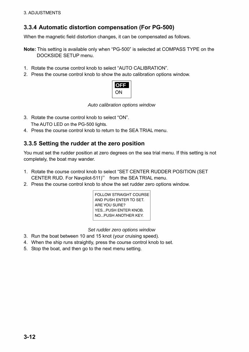
3.3.4 Automatic distortion compensation (For PG-500) When the magnetic field distortion changes, it can be compensated as follows. Note: This setting is available only when “PG-500” is selected at COMPASS TYPE on the
DOCKSIDE SETUP menu. 1. Rotate the course control knob to select “AUTO CALIBRATION”. 2. Press the course control knob to show the auto calibration options window.
ON
OFF
Auto calibration options window
3. Rotate the course control knob to select “ON”.
The AUTO LED on the PG-500 lights. 4. Press the course control knob to return to the SEA TRIAL menu. 3.3.5 Setting the rudder at the zero position You must set the rudder position at zero degrees on the sea trial menu. If this setting is not completely, the boat may wander. 1. Rotate the course control knob to select “SET CENTER RUDDER POSITION (SET
CENTER RUD. For Navpilot-511)” from the SEA TRIAL menu. 2. Press the course control knob to show the set rudder zero options window.
FOLLOW STRAIGHT COURSEAND PUSH ENTER TO SET.ARE YOU SURE?YES...PUSH ENTER KNOB.NO...PUSH ANOTHER KEY.
Set rudder zero options window 3. Run the boat between 10 and 15 knot (your cruising speed). 4. When the ship runs straightly, press the course control knob to set. 5. Stop the boat, and then go to the next menu setting.

3. ADJUSTMENTS
3-13
3.3.6 Memorizing your boat’s characteristics The automatic tuning enables the NAVpilot-500/511 system to automatically set up the two main steering parameters (rudder gain and counter rudder gain) for the boat. This procedure will shorten the learning time for the self-learning feature. However, as parameters are memorized over time, it is not necessary to complete the procedure. Do the following procedure in calm water. 1. Confirm that you have enough open water around you, and then run the boat straightly
between 10 and 12 knots straight to windward. 2. Rotate the course control knob to select “AUTO TUNING” from the SEA TRIAL menu. 3. Press the course control knob to show the auto tuning options window.
YESNO
Auto tuning options window
4. Rotate the course control knob to select “YES”. 5. Press the course control knob to start the auto tuning.
The boat runs in the AUTO mode. While tuning, the message “AUTO TUNIG – WAIT (**%) appears. When the auto tuning is completed, the message “AUTO TUNING IS COMPLETED” appears. (This tuning takes approx. 5 minutes.)
6. Press any key to finish.

3. ADJUSTMENTS
3-14
3.4 DISPLAY SETUP Menu The DISPLAY SETUP menu allows you to choose units of measurement. 1. Open the INSTALLATION menu. 2. Rotate the course control knob to select “DISPLAY SETUP”. 3. Press the course control knob to show the display setup menu.
SPEED UNIT:RANGE UNIT: nmWIND SPEED UNIT: ktDEPTH UNIT: ftWATER TEMP UNIT: FPOSITION FORMAT
DD MM. MMM" NEXT PAGE
kt
PREVIOUS PAGEHEADING DISPLAY: MAGNETICDATE FORMAT: MMM. DD. YYYYTIME FORMAT: 24HOURDATA BOX FORMAT: 3 BOXES
PUSH MENU KEY TO RETURN
TO PREVIOUS MENU.
PUSH MENU KEY TO RETURN
TO PREVIOUS MENU.
SPEED UNIT:
RANGE UNIT: nm
WIND SPEED UNIT: kt
DEPTH UNIT: ft
WATER TEMP UNIT: F
POSITION FORMAT: DD MM. MMM"
HEADING DISPLAY: MAGNETIC
DATE FORMAT: MMM. DD. YYYY
TIME FORMAT: 24HOUR
kt
DATA BOX FORMAT: 2 BOXES
PUSH MENU KEY TO RETURN
TO PREVIOUS MENU.
Navpilot-500 Navpilot-511
Display setup menu
To change pages, select “▼NEXT PAGE” or “▲PREVIOUS PAGE” and press the course control knob.
4. Rotate the course control knob to select the item desired. 5. Press the course control knob to show the speed unit options window. The example
below shows the speed unit options.
km/hMPH
kt
Speed unit options window, for example

3. ADJUSTMENTS
3-15
6. Rotate the course control knob to select option. See the table shown below detailed information.
7. Press the course control knob to finish.
Item Description Settings Speed Unit Choose unit of ship’s speed measurement. kt, km/h, MPH Range Unit Choose unit of range measurement. nm, km, sm, nm & yd
(YARD appears in TURN menu), nm & m, km & m, sm & yd
Wind Speed Unit Choose unit of wind speed measurement. kt, km/h, m/s, MPH Depth Unit Choose unit of depth measurement. ft, m, FA, P/B
(Passi/Braza) Water Temp Unit Choose unit of water temperature
measurement. °F, °C
Position Format Choose how many digits (or seconds) to display after decimal point in latitude and longitude position.
DD°MM.MM’, DD°MM.MMM’, DD°MM.MMMM’, DD°MM’ SS.S”
Next Page Previous PAGE Heading Readout
Choose heading display format. Magnetic, True
Date Format Choose the date display format. DD. MMM. YYYY, YYYY. MM. DD, MMM. DD. YYYY
Time Display Choose the time display format. 12 HOUR, 24 HOUR Data Box Format Choose the type of the data display. 2 BOXES, 3 BOXES
(1 BOX/2 BOXES for Navpilot-511)

3. ADJUSTMENTS
3-16
3.5 DATA CALIBRATION Menu The DATA CALIBRATION menu lets you offset speed, temperature and depth data to further refine accuracy referring to the appropriate sensors. Rotate the course control knob to select “DATA CALIBRATION” from the INSTALLATION MENU, and then press the course control knob to show the DATA CALIBRATION menu.
STW: 0 %TEMP: 18.00 FDEPTH: 0.0 ft
PUSH MENU KEY TO RETURNTO PREVIOUS MENU.
Data calibration menu
3.5.1 STW (CALIBRATION) Offset the speed through water data. 1. Rotate the course control knob to select “STW” from the DATA CALIBRATION menu. 2. Press the course control knob and the current value is circumscribed with a double
rectangle. 3. Rotate the course control knob to set offset (Setting range: -50% to +50%). 4. Press the course control knob to finish. 3.5.2 TEMP (CALIBRATION) Offset the water temperature data. 1. Rotate the course control knob to select “TEMP” from the DATA CALIBRATION menu. 2. Press the course control knob and the current value is circumscribed with a double
rectangle. 3. Rotate the course control knob to set offset (Setting range: -18.00 to +18.00°F). 4. Press the course control knob to finish. 3.5.3 DEPTH (CALIBRATION) Offset the depth data. 1. Rotate the course control knob to select “DEPTH” from the DATA CALIBRATION menu. 2. Press the course control knob and the current value is circumscribed with a double
rectangle. 3. Rotate the course control knob to set offset (Setting range: -30.0 to 300.0 ft). 4. Press the course control knob to finish.

3. ADJUSTMENTS
3-17
3.6 Other Settings 3.6.1 Setting the remote controller When connecting the optional remote controller(s), the settings of the remote controller port and course in the FU or NFU mode are necessary. Setting remote controller port
Set the type of the remote controller connected to the REMOTE1 and REMOTE 2 ports on the processor unit. 1. Open the INSTALLATION menu. 2. Rotate the course control knob to select “SYSTEM SETUP”. 3. Press the course control knob to show the SYSTEM SETUP menu.
KEY BEEP:LOCK: UNLOCKLANGUAGE: ENGLISHPANNEL DIMMER: 8REMOTE CONTROLLER 1: NFUREMOTE CONTROLLER 2: NFUCSE AFTER REMOTE:
PRESENT COURSEPORT 1 NAME: PORT 1NMEA0183 V1.5 DATA OUTPORT 2 NAME: PORT 2NMEA0183 V1.5 DATA OUTSIMULATION MODE: OFFTEST: OFFRECEIVE SCREEN SETUP DATA:
NOMEMORY CLEAR: ALL CLEAR
OFF KEY BEEP: ONLOCK: UNLOCKLANGUAGE: ENGLISHPANEL DIMMER: 8REMOTE CONT 1: NFUREMOTE CONT 2: NFUCSE AFTER REMOTE: PRESENTSIMULATION MODE: OFFRECEIVE SCREEN SETUP: NO
RECEIVING SENTENCEPORT1 NAME: _ NMEA0183 V1.5 DATA OUTPORT2 NAME: _ NMEA0183 V1.5 DATA OUTTEST: OFFCLEAR SETUP DATA: NO
Navpilot-500 Navpilot-511
System setup menu
4. Rotate the course control knob to select “REMOTE CONTROLLER 1” or “REMOTE CONTROLLER 2” from the SYSTEM SETUP menu.
5. Press the course control knob to show the remote controller options window.
FUDODGEDISABLE
NFU
Remote controller 1, 2 options window
6. Rotate the course control knob to select the type of remote controller connected. NFU: Select for button or lever remote controller connection. FU: Select for dial remote controller connection. DODGE: Select for dodge remote controller (FAP-6232) connection. DISABLE: Disable remote controller operation.
7. Press the course control knob.

3. ADJUSTMENTS
3-18
Selecting course after the REMOTE mode is off
When the remote controller is turned off while in the AUTO mode, the “COURSE AFTER REMOTE” mode can be chosen as shown below. 1. Rotate the course control knob to select “CSE AFTER REMOTE”, and then press it to
show the course after remote options window.
PRESENT COURSE
PREVIOUS COURSE
Course after remote options window (Ex. Navpilot-500)
PREVIOUS (COURSE): The previous course before using the remote controller. PRESENT (COURSE): The heading at the moment the remote controller is turned off.
Previous course
New course
Remote controller: OFF Remote
controller: ON
PRESENT COURSE mode
Remote controller: ON
Remote controller: OFF
Previous course
PREVIOUS COURSE mode Course after remote controller is turned off
2. Rotate the course control knob to select PRESENT (COURSE) or PREVIOUS
(COURSE) as appropriate. 3. Press the course control knob.

3. ADJUSTMENTS
3-19
3.6.2 NMEA port setup Setting the name for port
You can set the name for each port to distinguish them. This name will be used to select the navigation source. 1. Open the SYSTEM SETUP menu referring the previous paragraph. 2. Rotate the course control knob to select “PORT1 NAME” or “PORT 2 NAME.” 3. Press the course control knob. 4. Use the course control knob to enter the name desired.
To move the cursor, press the [PORT] or [STBD] key appropriately. 5. Press the [MENU] key to finish. Setting the NMEA format
Set the format for the NMEA 1 IN/OUT (PORT 1) port and NMEA 2 OUT (PORT 2) port. 1. Open the SYSTEM SETUP menu referring the previous paragraph. 2. Rotate the course control knob to select the NMEA version below of “PORT 1” or “PORT
2.” 3. Press the course control knob to show the options window. 4. Rotate the course control knob to select appropriate format.
Setting item Output format Input format NMEA0183 V1.5 NMEA0183 Ver. 1.5 NMEA0183 V2.0 NMEA0183 Ver. 2.0 NMEA0183 V3.0 NMEA0183 Ver. 3.0
NMEA0183 Ver. 1.5, 2.0, 3.0
NMEA 38400BPS* Baud rate: 38400 bps FI-30 FORMAT For connection of FI-30 series
*: Sentences are same as NMEA V3.0. 4. Press the course control knob. Note: When selecting FI-30 FORMAT, turn off the NAVpilot-500 and FI-30 at the same time
always. Otherwise, data will be lost.

3. ADJUSTMENTS
3-20
Setting the sentences
Select the sentences to output from NMEA IN/OUT (PORT 1) and NMEA OUT (PORT 2) ports. 1. Open the SYSTEM SETUP menu referring to the previous paragraph. 2. Rotate the course control knob to select “DATA OUT” of PORT 1 or PORT 2 as
appropriate. 3. Press the course control knob to show the options window.
The option window is displayed according to the setting of “PORT 1 FORMAT” (“PORT 2 FORMAT).
AAM ONBWC OFFBWR OFFDBT ONGGA OFFGLL ONGTD ON
HDM ONHDT OFFHSC OFFMTW ONRMA ONRMB ONRMC ON
VHW ONVWR ONVWT OFFVTG ONWPL OFFXTE ONZDA OFF
AAM ONASD OFFBWC OFFBWR OFFDBT OFFDPT ONGGA ONGLL ON
GLC OFFHDG OFFHDT OFFHSC OFFMTW ONMWV ONRMA ONRMB ON
RMC ONRSA ONVBW OFFVHW ONVTG ONWPL OFFXTE ONZDA OFF
AAM ONALR ONBWC OFFBWR OFFDBT ONDPT ONGGA ONGLC OFFGLL ON
GNS OFFHDG OFFHDT OFFHSC OFFMTW ONMWV ONRMA ONRMB ONRMC ON
RSA OFFVBW ONVHW ONVTG ONWPL OFFXTE ONZDA OFF
AAM OFFALR OFFBWC OFFBWR OFFDBT OFFDPT OFFGGA OFFGLC OFFGLL OFF
GNS OFFHDG OFFHDT OFFHSC OFFMTW OFFMWV OFFRMA OFFRMB OFFRMC OFF
RSA OFFVBW OFFVHW OFFVTG OFFWPL OFFXTE OFFZDA OFF
VER 1.5 VER 2.0
VER 3.0 NMEA 38400 BPS
Sentence selecting window
4. Rotate the course control knob to select the sentence desired. 5. Press the course control knob to show the sentence options window.
ON
OFF
Sentence options window
6. Rotate the course control knob to select ON or OFF as appropriate. 7. Press the course control knob. 8. Repeat steps 4 through 7 to complete. 9. Press the [MENU] ([TURN/MENU]) key to return to the SYSTEM SETUP menu.

3. ADJUSTMENTS
3-21
Using settings selected on other control unit
You can use the display settings selected on other control unit. 1. Open the SYSTEM SETUP menu. 2. Rotate the course control knob to select “RECEIVE SCREN SETUP NO”. 3. Press the course control knob to show the optional window. 4. Rotate the course control knob to select the control unit No. from which you want to
copy settings. 5. Press the course control knob. Confirming the input sentences
The RECEIVING SENTENCE window shows the current input sentences. 1. Open the SYSTEM SETUP menu. 2. Rotate the course control knob to select “RECEIVING SENTNECE”. 3. Press the course control knob to show the RECEIVING SENTENCE window.
RECEIVING SENTENCE
AAM BWR GCC HDM RMC VWT
APA DBT GNS MTW VBW WPL
APB DPT GTD MWV VHW XTE
BOD GGA HDG RMA VYG ZDA
BWC GLC HDT RMB VWR
PUSH MENU KEY TO RETURN
TO PREVIOUS MENU.
Currentinput
sentence
Receiving sentence window
4. Confirm the current input sentences (in reverse video). 5. Press the [MENU] ([TURN/MENU]) key to close the window.

3. ADJUSTMENTS
3-22
3.6.3 Clearing all data All memories can be cleared to restore default settings. 1. Open the DOCKSIDE SETUP menu. 2. Rotate the course control knob to select COMPASS TYPE, and then press the course
control knob. 3. Rotate the course control knob to select “OTHER”, and then press the course control
knob. 4. Press the [MENU] key twice to close the INSTALLATION menu. 5. Press the [MENU] key to show the main menu. 6. Rotate the course control knob to select SYSTEM SETUP, and then press the course
control knob. KEY BEEP:LOCK: UNLOCKLANGUAGE: ENGLISHPANNEL DIMMER: 1REMOTE CONTROLLER 1: NFUREMOTE CONTROLLER 2: NFUCSE AFTER REMOTE:
PRESENT COURSE NEXT PAGE
OFF
PREVIOUS PAGE
PORT 1 FORMAT: NMEA0183 V1.5 DATA OUTPORT 2 FORMAT: NMEA0183 V1.5 DATA OUTSIMULATION MODE: OFFMEMORY CLEAR: NO
Page 1
Page 2
PUSH MENU KEY O RETURNTO PREVIOUS MENU.
PUSH MENU KEY O RETURNTO PREVIOUS MENU.
System setup menu (through the main menu)
7. Rotate the course control knob to select MEMORY CLEAR at the bottom of the second page, and then press the course control knob to show the option window.
DISPLAY CLEAR
ALL CLEAR
Memory clear option window
8. Rotate the course control knob to select “ALL CLEAR”, and then press the course control knob. You are asked if you are sure to clear memory.
9. Press the course control knob to clear, or press any key to escape. When the course control knob is pressed, the equipment restarts automatically.

3. ADJUSTMENTS
3-23
3.6.4 Running simulation program The simulation mode provides simulated operation to help acquaint users with the many features of the Navpilot-500/511. It allows you to view and control a simulated autopilot without position-fixing equipment. Most controls are operative so you may practice using the Navpilot-500/511. You may turn the simulation mode on or off as follows:
WARNINGDo not use the SIMULATION mode on the boat.
The rudder may move. This is special-purpose mode for technicians.
Available steering mode AUTO, NAV, DODGE mode
Available operation Heading, Rudder angle, Alarms, Waypoint switch, Wind data, Depth, Speed, Time
1. Open the SYSTEM SETUP menu. 2. Rotate the course control knob to select “SIMULATION MODE”. 3. Press the course control knob to show the simulation mode options window.
ON
OFF
Simulation mode options window
4. Rotate the course control knob to select ON or OFF as appropriate. 5. For “ON”, enter the course value manually using the course control knob. 6. Press the course control knob. In the simulation mode, the message “SIM” blinks on any display. Note that when turning the power of while the simulation mode is on, you will be asked at the next power-up if you want to continue the simulation mode.
STBY
359.9RUDDER
HDGM
040 20 10 402010
Simuration mark SIM
Simulation mark (ex. STBY mode)

3. ADJUSTMENTS
3-24
This page is intentionally left blank.

NAME
OUTLINE
Q'TY
DESCRIPTION/CODE №
PACKING LIST
PACKING LIST
PACKING LIST
PACKING LIST
64AU-X-9852-5
NAVpilot-500-J-*A/E-*A
NAVpilot-500-J-*A/E-*A
NAVpilot-500-J-*A/E-*A
NAVpilot-500-J-*A/E-*A
1/2
NAME
OUTLINE
Q'TY
DESCRIPTION/CODE №
ユニット
ユニット
ユニット
ユニット
UNIT
UNIT
UNIT
UNIT
操作部
CONTROL UNIT
FAP-5001-J
000-090-281
1
**
制御部
PROCESSOR UNIT
FAP-5002
000-090-283
1
追従発信器
RUDDER REFERRENCE UNIT
FAP-6111-100
000-090-284
1
**
制御部予備品
制御部予備品
制御部予備品
制御部予備品
PROCESSOR UNIT SPARE PARTS
PROCESSOR UNIT SPARE PARTS
PROCESSOR UNIT SPARE PARTS
PROCESSOR UNIT SPARE PARTS
SP64-01401
SP64-01401
SP64-01401
SP64-01401
ヒューズ
FUSE
FGMB 4A AC125V
000-119-976
2
操作部付属品
操作部付属品
操作部付属品
操作部付属品
CONTROL UNIT SPARE PARTS
CONTROL UNIT SPARE PARTS
CONTROL UNIT SPARE PARTS
CONTROL UNIT SPARE PARTS
FP64-01001
FP64-01001
FP64-01001
FP64-01001
コネクタ(MJ)終端器
TERMINATOR
MJ-A7SPF0011
000-147-017
1
操作部工材
操作部工材
操作部工材
操作部工材
CONTROL UNIT INSTALLATION MATERIALS
CONTROL UNIT INSTALLATION MATERIALS
CONTROL UNIT INSTALLATION MATERIALS
CONTROL UNIT INSTALLATION MATERIALS
CP64-02200
CP64-02200
CP64-02200
CP64-02200
ケーブル組品MJ
CABLE ASSY.
MJ-A7SPF0010-100
000-147-018
1
ミガキ平座金
FLAT WASHER
M4 SUS304
000-864-126
4
冷間圧造蝶ナット
WING NUT
M4 SUS304
000-863-331
4
バネ座金
SPPING WASHER
M4 SUS304
000-864-256
4
寸切ボルト
THREADED ROD
M4X50 SUS304
000-147-539
4
制御部工材
制御部工材
制御部工材
制御部工材
PROCESSOR UNIT INSTALLATION MATERIALS
PROCESSOR UNIT INSTALLATION MATERIALS
PROCESSOR UNIT INSTALLATION MATERIALS
PROCESSOR UNIT INSTALLATION MATERIALS
CP64-02210
CP64-02210
CP64-02210
CP64-02210
ケーブル組品MJ
CABLE ASSY.
MJ-A7SPF0010-150
000-148-507
1
コンベックス
PLASTIC BAND
CV-150
000-570-325
40
+トラスタッピンネジ
+TAPPING SCREW
5X20 SUS304 1シュ
000-802-081
4
追従発信器工材
追従発信器工材
追従発信器工材
追従発信器工材
RUDDER REFERENCE UNIT INSTALLATION MATERIALS
RUDDER REFERENCE UNIT INSTALLATION MATERIALS
RUDDER REFERENCE UNIT INSTALLATION MATERIALS
RUDDER REFERENCE UNIT INSTALLATION MATERIALS
CP64-01700
CP64-01700
CP64-01700
CP64-01700
ガスケット(3)
GUSKET
64-019-5009-0
100-205-550
1
ミガキ平座金
FLAT WASHER
M4 SUS304
000-864-126
4
連結棒
CONNECTING ROD ASSY.
CP64-01710
009-013-210
1
+トラスタッピンネジ
TAPPING SCREW
4X20 SUS304
000-805-687
4
1.コ
-ド番号末尾の
[**]は
、選択品の代表型式
/コートを
表します。
CO
DE N
UM
BER
EN
DED
BY "
**" IN
DIC
ATES T
HE N
UM
BER
OF T
YP
ICA
L M
ATER
IAL.
(略図の寸法は、参考値です。 DIMENSIONS IN DRAWING FOR REFERENCE ONLY.)
(略図の寸法は、参考値です。 DIMENSIONS IN DRAWING FOR REFERENCE ONLY.)
(略図の寸法は、参考値です。 DIMENSIONS IN DRAWING FOR REFERENCE ONLY.)
(略図の寸法は、参考値です。 DIMENSIONS IN DRAWING FOR REFERENCE ONLY.)
64AU-X-9852

NAME
OUTLINE
Q'TY
DESCRIPTION/CODE №
PACKING LIST
PACKING LIST
PACKING LIST
PACKING LIST
64AW-X-9855-0
NAVpilot-511-J/E-1A/2A
NAVpilot-511-J/E-1A/2A
NAVpilot-511-J/E-1A/2A
NAVpilot-511-J/E-1A/2A
1/2
NAME
OUTLINE
Q'TY
DESCRIPTION/CODE №
ユニット
ユニット
ユニット
ユニット
UNIT
UNIT
UNIT
UNIT
操作部
CONTROL UNIT
FAP-5011-J
000-090-303
1
**
制御部
PROCESSOR UNIT
FAP-5002-11
000-090-311
1
追従発信器
RUDDER REFERRENCE UNIT
FAP-6111-100
000-090-284
1
**
制御部予備品
制御部予備品
制御部予備品
制御部予備品
PROCESSOR UNIT SPARE PARTS
PROCESSOR UNIT SPARE PARTS
PROCESSOR UNIT SPARE PARTS
PROCESSOR UNIT SPARE PARTS
SP64-01401
SP64-01401
SP64-01401
SP64-01401
ヒューズ
FUSE
FGMB 4A AC125V
000-119-976
2
操作部付属品
操作部付属品
操作部付属品
操作部付属品
CONTROL UNIT SPARE PARTS
CONTROL UNIT SPARE PARTS
CONTROL UNIT SPARE PARTS
CONTROL UNIT SPARE PARTS
FP64-01001
FP64-01001
FP64-01001
FP64-01001
コネクタ(MJ)終端器
TERMINATOR
MJ-A7SPF0011
000-147-017
1
操作部工材
操作部工材
操作部工材
操作部工材
CONTROL UNIT INSTLLATION MATERIALS
CONTROL UNIT INSTLLATION MATERIALS
CONTROL UNIT INSTLLATION MATERIALS
CONTROL UNIT INSTLLATION MATERIALS
CP64-02401
CP64-02401
CP64-02401
CP64-02401
六角ナット 一種
HEX.NUT
M4 SUS304
000-863-106
4
ミガキ平座金
FLAT WASHER
M4 SUS304
000-864-126
4
寸切ボルト
THREADED ROD
M4X50 SUS304
000-147-539
4
バネ座金
SPPING WASHER
M4 SUS304
000-864-256
4
制御部工材
制御部工材
制御部工材
制御部工材
PROCESSOR UNIT INSTLLATION MATERIALS
PROCESSOR UNIT INSTLLATION MATERIALS
PROCESSOR UNIT INSTLLATION MATERIALS
PROCESSOR UNIT INSTLLATION MATERIALS
CP64-02201
CP64-02201
CP64-02201
CP64-02201
+トラスタッピンネジ
+TAPPING SCREW
5X20 SUS304 1シュ
000-802-081
1
コンベックス
PLASTIC BAND
CV-150
000-570-325
40
追従発信器工材
追従発信器工材
追従発信器工材
追従発信器工材RUDDER REFERENCE UNIT INSTLLATION MATER
RUDDER REFERENCE UNIT INSTLLATION MATER
RUDDER REFERENCE UNIT INSTLLATION MATER
RUDDER REFERENCE UNIT INSTLLATION MATERCP64-01700
CP64-01700
CP64-01700
CP64-01700
連結棒
CONNECTING ROD ASSY.
CP64-01710
009-013-210
1
ガスケット(3)
GUSKET
64-019-5009-0
100-205-550
1
ミガキ平座金
FLAT WASHER
M4 SUS304
000-864-126
4
+トラスタッピンネジ
TAPPING SCREW
4X20 SUS304
000-805-687
1
図書
図書
図書
図書
DOCUMENT
DOCUMENT
DOCUMENT
DOCUMENT
操作要領書
OPERATOR'S GUIDE
OSJ-72501-*
000-148-629
1
**
1.コ
-ド番号末尾の
[**]は
、選択品の代表型式
/コートを
表します。
CO
DE N
UM
BER
EN
DED
BY "
**" IN
DIC
ATES T
HE N
UM
BER
OF T
YP
ICA
L M
ATER
IAL.
(略図の寸法は、参考値です。 DIMENSIONS IN DRAWING FOR REFERENCE ONLY.)
(略図の寸法は、参考値です。 DIMENSIONS IN DRAWING FOR REFERENCE ONLY.)
(略図の寸法は、参考値です。 DIMENSIONS IN DRAWING FOR REFERENCE ONLY.)
(略図の寸法は、参考値です。 DIMENSIONS IN DRAWING FOR REFERENCE ONLY.)
64AW-X-9855


FURUNO ELECTRIC CO., LTD.
1 2 4 5 63
DRAWN
CHECKED
APPROVED
SCALE
DWG No.
MASSkg
TITLE
名称
NAME
相互結線図
INTERCONNECTION DIAGRAM
B
A
D
C
オートパイロット
AUTOPILOT
NOTE
*2. OPTION.*1. SHIPYARD SUPPLY.
*2)オプション。*1)造船所手配。注記
123456
+12V
SHIELD 7GND
WHTBLUYELGRNREDBLK
シロアオキミドリアカクロ
P_SWGND
CAN2-ACAN2-B
TB91234567
GND
PWR_SW-HPWR_SW-CCAN-ACAN-B
C_GND
J1
12V_P
1234567
GND
PWR_SW-HPWR_SW-C
CAN-ACAN-B
C_GND
12V_P
MJ-A7SPFMJ-A7SPF
10m,φ61234567
GND
PWR_SW-HPWR_SW-CCAN-ACAN-B
C_GND
J1
12V_P
1234567
GND
PWR_SW-HPWR_SW-C
CAN-ACAN-B
C_GND
12V_P
MJ-A7SPF MJ-A7SPFMJ-A7SPF001010m,φ6
1234567
GND
PWR_SW-HPWR_SW-CCAN-ACAN-B
C_GND
J1
12V_P
1234567
GND
PWR_SW-HPWR_SW-C
CAN-ACAN-B
C_GND
12V_P
MJ-A7SPF
MJ-A7SPF0011
MJ-A7SPF0010,10m,φ6TERMINATOR
MJ-A7SPF0010
1
5
78910
MJ-A10SPF
REM-PREM-SIG
REM-NREM-SWREM-COM
NCNCNCNCFG
J2-J4
326
4
123456SHIELD
GND
REM1-PREM1-SIGREM1-N
REM1-SW
MJ-A10SPF0002,10m,φ61
5
78910
MJ-A10SPF
326
4
J1REM-PREM-SIGREM-NREM-SWREM-COMNCNCNCNCFG
FAP-6800DISTRIBUTOR
分配器
モモ/アカキ/アカモモ/クロミズ/クロミズ/アカ
YEL/REDPNK/BLK
L-BLU/BLKL-BLU/RED
PNK/RED
123456SHIELD
GND
BLUYELGRN
アオキミドリ
REDアカチャ BRN
TB11REM1-P
REM1-SIGREM1-N
REM1-SW
FAP-5552REMOTE CONTROLLER REMOTE CONTROLLER
FAP-6212FAP-6222
12345
TB13RRU_P
RRU-SIG1RRU_SIG2
RRU_NSHIELD
GRNミドリYELキ
FAP-6111
RUDDER REFERENCEUNIT
TB12
遠隔管制器 遠隔管制器
追従発信器
REMOTE CONTROLLERFAP-5551
REMOTE CONTROLLERFAP-6211FAP-6221
REMOTE CONTROLLERFAP-6231
遠隔管制器 遠隔管制器 遠隔管制器
REMOTE CONTROLLERFAP-6232
遠隔管制器
12
TB1(+)(-)
123 GND
SOL-B/MOTOR-SOL-A/MOTOR+TB2
SOL-ASOL-B
SOL-COM
SOL-ASOL-B
SOLENOID VALVE
REVERSIBLE PUMPリバーシブルポンプ
電磁弁
終端器
*2 *2
*2
12-24VDC
GNDIV-1.25SQ
*1
AWG
AWG
*3
*3
123
TB3B/C_POWERB/CSHIELD
MOTOR+MOTOR-
BYPASS/CLUTCH+BYPASS/CLUTCH-
外部アラームEXTERNAL ALARM
AWG*3HYDRAULIC LINER
DRIVE
クラッチ
456
EXT_BUZZ-AEXT_BUZZ-BSHIELD
クロシロ WHT
BLK
MJ-A6SPF0003,5m,φ6
GNDIV-1.25SQ
*1
12345
TB7NMEA_OUT1-ANMEA_OUT1-BNMEA_IN1-ANMEA_IN1-BSHIELD
12345 SHIELD
TB6POWERGNDNMEA_OUT2-ANMEA_OUT2-B
*2
123456
NCSHIELD
NMEA1 IN/OUT
NMEA2 OUT
12345 SHIELD
TB5POWERGNDNMEA_IN2-ANMEA_IN2-B
P
123456
TB8HD_IN-AHD_IN-BHD_OUT-AHD_OUT-B+12V
SHIELD7GND
WHTBLUYELGRNREDBLK
シロアオキミドリアカクロ
1234567
GND
MJ-A7SPFMJ-A7SPF0010,10m,φ6J3
+12V
SHIELD
HDG
12345 SHIELD
TB4TDRDGNDNC
GND
RXDTXD
DTRDSRRTSCTS
(RS-232C)
PCパソコン
RS232C
REM A
CONTROL A
制御部 PROCESSOR UNITFAP-5002
123456
+12V
SHIELD 7GND
WHTBLUYELGRNREDBLK
シロアオキミドリアカクロ
P_SWGND
CAN2-ACAN2-B
TB10 MJ-A7SPF0010,10m,φ6
同上DITTO
CONTROL B
RRU
REM B航法装置
マルチディスプレイMULTI DISPLAYRD-30 *2
1234
TD-ATD-BRD-HRD-C
NMEA2 IN
123456 SHIELD
NC
SHIFT-HSHIFT-C
DATA-HDATA-C
J1
123456 SHIELD
NC
MJ-A6SPF
MJ-A6SPF J2
RADAR(AD-10 FORMAT)
レーダー
航法装置NAV. EQUIPMENT(NMEA FORMAT)
TD-ATD-BRD-HRD-C
NAV EQUIPMENT
PG-500
HEADINGSENSOR
ヘディングセンサー
TD-HTD-C
P
YELGRN
キミドリ
WHTシロクロ BLK
RD-HRD-C
SENSORセンサー
7
+VGNDFG
56
12-24V
MJ-A7SPF0009,2m,φ6*2
YELGRN
キミドリ
12m
10m
J2 J2 J2
FAP-5001CONTROL UNIT
操作部
FAP-5001CONTROL UNIT
操作部
FAP-5001CONTROL UNIT
操作部
FAP-5011 FAP-5011FAP-501112/24 VDC
NAVpilot-500/511
SECTION OF CORE
12 VDC 24 VDC
SECTION OF CORE(mm ) (mm )
2 2
MOTOR VOLTAGE
AWG
10
AWG
16 m or less
3 m or less
6 m or less
2.5
10
12
6
2.5
2.5
6
12
12
8
*3. REFER TO TABLE1.
*3)TABLE1参照。
RELAY CONTACT (MAX. 3 A)
10 m or less 6 8 4 10
CABLELENGTH
4
TABLE 1
TXD-HTXD-CRXD-HRXD-C
Mar. 3 '04 K.MIYAZAWA
TAKAHASHI.T
C7250-C01- E