installation & operating manual - … · 2006-02-20 · deactivating wagner hydraulic pumpsets...
TRANSCRIPT
INSTALLATION & OPERATING MANUAL
. . .. :
REM THIS MANUAL CAREFULLY BEFORE ATTEMPTINGINSTALLATION or OPERATION of AUTOPILOT
I PLEASE READ IT
SALES MO SERVICE IN OVER 60 COUNTRIES
Ref. No.790-004
ISSUE:September/84

S P E C I A L N O T I C E
An Autopilot is not intended to take the place of a man, but rather assist himIn steering the vessel.
It is the responsibility of the man (and a requirement by law) to ensure andmaintain safe navigation and control of the vessel at all times in accordancewith the Rules of the Road.
An Autopilot is intended for operation in open waters, clear of all obstructionsand other vessels. The heading of the vessel must be observed constantly.
It may be necessary to regain manual steering control quickly and to deactivatethe Autopilot pumpset if the vessel alters or fails to maintain the set courseor if the set course may jeopardize the vessel.
DEACTIVATING WAGNER HYDRAULIC PUMPSETS
1. WAGNER Type 2A, PV125C-XX-SC, and PVl25R-XX-RC pumpsets can be deactivatedby disconnecting the power going to terminals 1 and 2 in the pumpsetelectrical connection boxes. Install a separate switch if necessary.
2. Electrical motor driven pumpsets can be deactivated by disconnecting thepower going to the electric motor. Install a separate switch or breakerif necessary.
3. Engine-driven pumpsets with No. 1 and No. 2 Uniblocks can only be deactivatedby turning the Uniblock flow control knob to the "OFF" Position. ReadSection E of the No. 1 and No. 2 Uniblock Manual. (Ref. No. 190-0006)
After turning the Uniblock flow control knob to the "OFF" position, confirmthat the Autopilot will NOT operate the rudder,
Reset the flow rate to produce between 14 and 18 seconds rudder hardover tohardover. Secure flow control knob locking screw. 00 not secure this screwtoo tightly. Be certain that the flow control knob can, with effort, beturned to the "OFF" position in an emergency.
INSTALLATION AND OPERATING MANUAL
PAGE INDEX
3 'WARRANTY
4 GENERAL DESCRIPTION of the WAGNER S.E. AUTOPILOT
5 SECTION I: AUTOPILOT CONTROLS
SEA STATE
RUDDER
COURSE SETTING
OPERATION of REMOTE COURSE SETTING STATIONS
7 SECTION II: INSTALLATION PROCEDURE
7 A. MOUNTING BASIC COMPONENTS
1. WAGNER COMPASS
2. CONTROL UNIT
3. DRIVE UNIT
4. REMOTE STATIONS
9 B. INTERCONNECTING CABLES
12
12
13
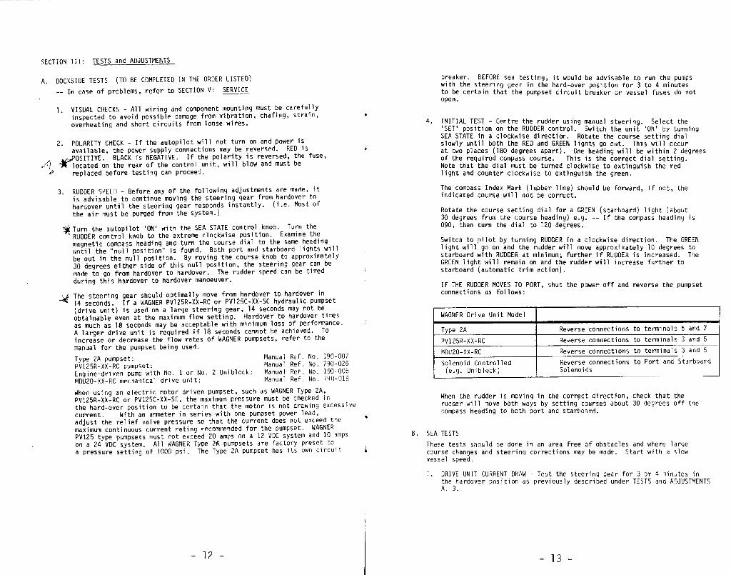
SECTION III: TESTS AND ADJUSTMENTS
A. DOCKSIDE TESTS
1. VISUAL CHECKS
2. POLARITY CHECK
3. RUDDER SPEED
4. INITIAL TEST
B. SEA TESTS
1. Drive Unit CURRENT DRAW
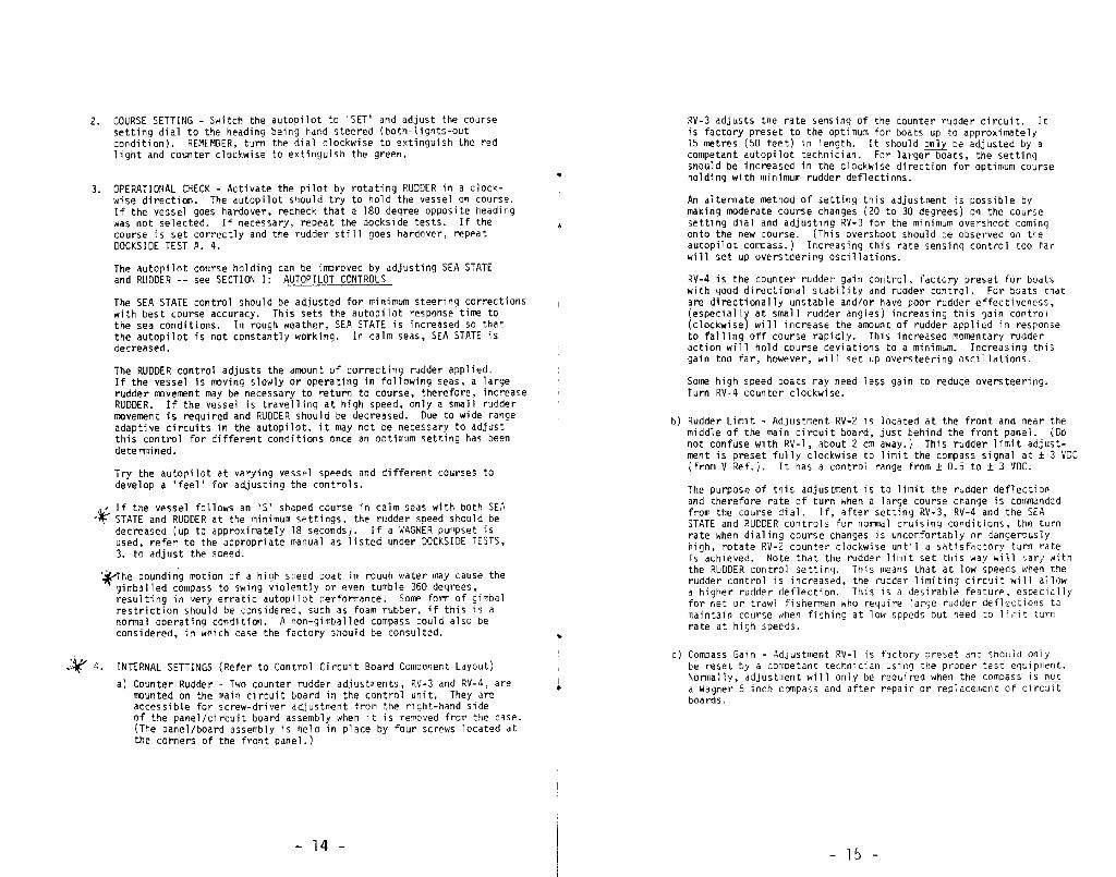
2. COURSE SETTING
3. OPERATIONAL CHECK
4. INTERNAL SETTINGS
a) Counter Rudder
b) Rudder Limit
c) Compass Gain
-l-

PAGE INDEX (continued)
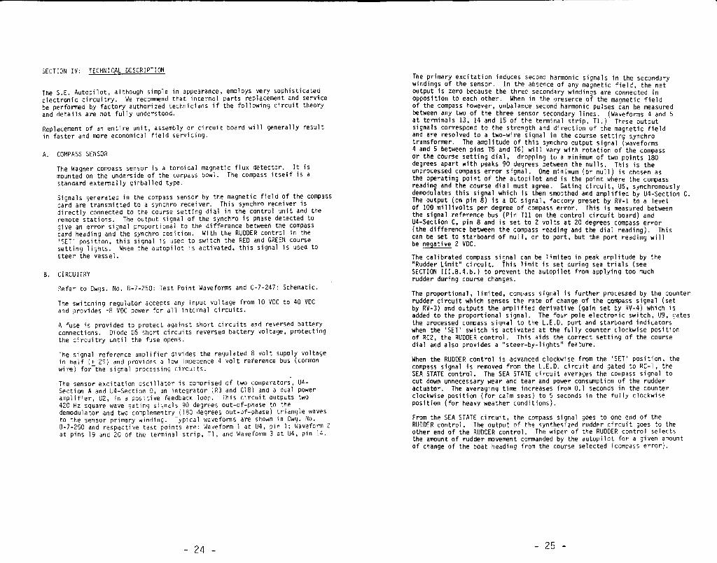
24 SECTION IV: TECHNICAL DESCRIPTION
24 A. COMPASS SENSOR
24 B. CIRCUITRY
28 SECTION V: SERVICE
28 A. ROUTINE MAINTENANCE
28 B. TROUBLE SHOOTING
31
31
31
34
6
10
11
17
18
20
22
22
23
27
30
SECTION VI: HYDRAULICS
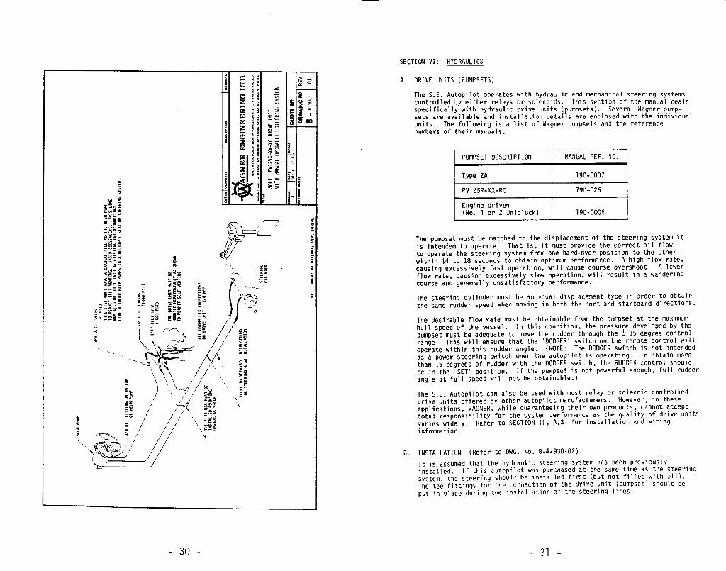
A. DRIVE UNITS (PUMPSETS)
B. INSTALLATION
1. PIPING THE SYSTEM
2. RECOMMENDED OILS
3. FILLING THE SYSTEM
C. SERVICE
Drawings and Lists in this Manual
A-8-217 S.E. Autopilot Cabling Diagram
A-7-251-01 Control Unit Wiring Diagram
A-7-252-01 Remote Station Wiring Diagram
Control Unit Parts list
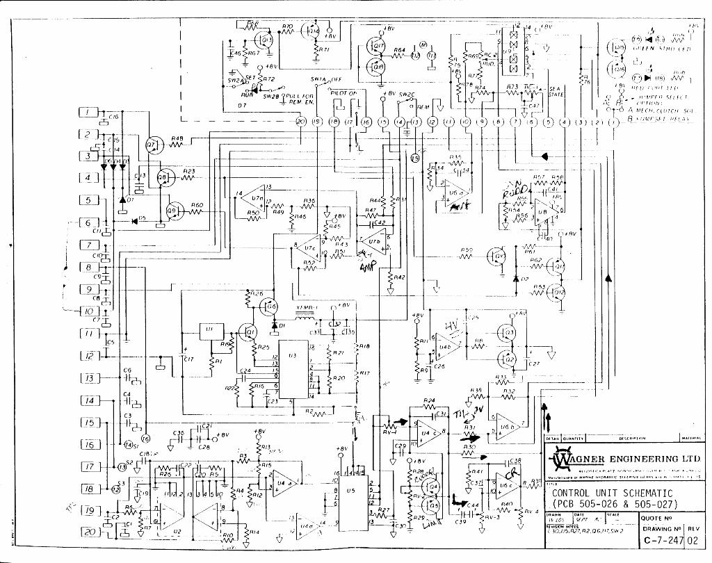
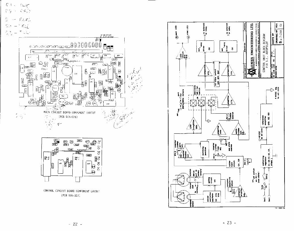
C-7-247 Control Unit Schematic
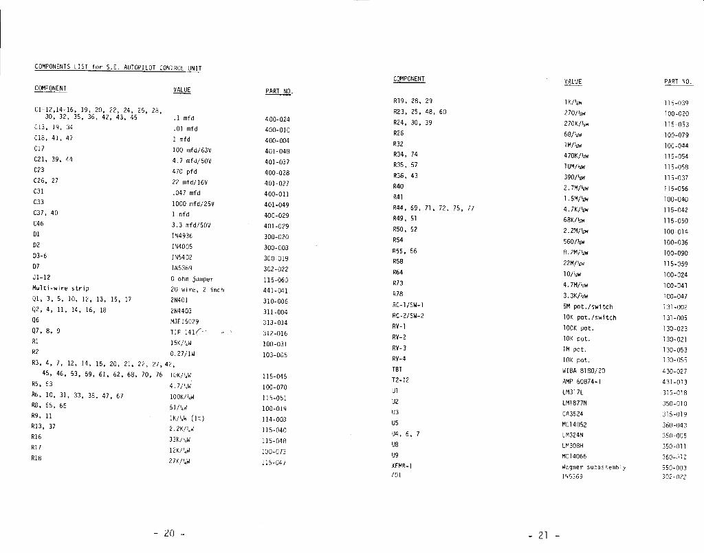
Control Unit Components List
Main Circuit Board Component Layout
Control Circuit Board Component Layout
B-7-248 Control Unit Block Diagram
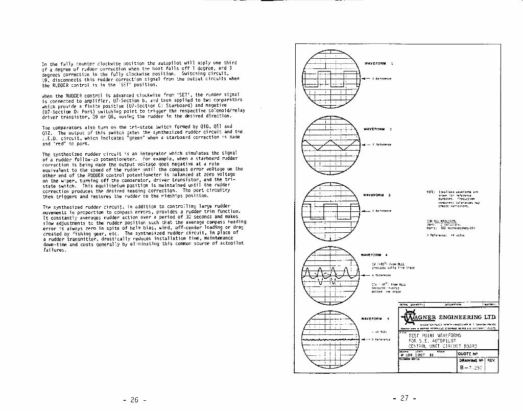
B-7-250 Control Unit Test Point Waveforms
B-4-930-02 Drive Unit with Manual Hydraulic Steering
-2-
WARRANTY OF WAGNER ENGINEERING LTD.(HEREINAFTER CALLED WAGNER)
WAGNER warrants that all products of its manufacture meet high standardsof quality and performance and are warranted to be free from defectivematerials and workmanship when used in the manner and service intended fora period of twelve months after delivery.
This warranty provides labour during normal working hours only. and on thepremises of WAGNER.
In the event that WAGNER is required to perform warranty work outside theirnormal working hours or place of business. the following costs or expensesshall be paid for by the customer:
1. All transportation to the job site and return to the normal place ofbusiness.
2. All travelling time to the job site and return to the normal place ofbusiness -- at current service rates.
3. All labour far gaining access to, removing, servicing, replacing andtesting WAGNER products, including waiting time -- at current servicerates.
4. All labour perfoad by others.
5. Reasonable living expenses if personnel are unable to return to theirnormal place of business in the same day.
6. All communication charges.
7. All customs duties.
WAGNER will not assume any costs or expenses for special, direct. incidentalor consequential damages.
In the case of products suppled, but not manufactured by WAGNER thewarranty will be that of the original manufacturer only.
All products eligible for warranty claims must be sent freight prepaid toWAGNER accompanied by a copy of the original delivery documentation anddetails of the complaint. All goods will be returned freight collect bythe least expensive means unless advised otherwise. The warranty will notbe honoured if, upon examination, i t is determined that the equipment hasbeen abused, modified, misapplied, misused, neglected, or contaninated
Address returned goods to:
Phone: (604: 988-1111
- 3-
Telex: 04-352755
Cable: “WAGENG”
GENERAL DESCRIPTION of the WAGNER S.E. AUTOPILOT
The WAGNER S.E. AUTOPILOT is a complete automatic steering control Systemincorporating the latest solid state components. The basic system consistsof a control unit and a magnetic compass with a course sensor. The auto-pilot system operates on any voltage from 10 to 40 VOC without modification.
The control unit has wide range controls and uses proportional, integraland differential circuits. SEA STATE (damping) control with a maximum
* sensitivity of 0.5 degrees optimizes course accuracy in all sea conditions.RUDDER control alters the amount of rudder applied in response to sea andspeed changes. A counter rudder circuit senses the rate of change of thecourse heading and varies the amount of rudder applied accordingly.Automatic rudder trim counteracts persistent course errors due to sidewinds, waves, current or imbalance of the vessel. Port and starboardindicator lights assist course setting and display steering activity.
The S.E. AUTOPILOT operates with hydraulic and mechanical steering systemscontrolled by either relays or solenoids which in turn control the lengthof time and in which direction the steering gear will operate. The reldyor solenoid controlled 'drive unit' may be a WAGNER product or be suppliedby the customer after verifying system compatibility.
A hand-held remote course setting station, Model RP-50, which includes. a'DODGER' switch is optionally available.
The S.E. AUTOPILOT can also be guided by the ultra-precise automated naviga-tion capabilities of most Loran C receivers and some Satnavs and Deccareceivers through the addition of the Wagner Tracker LT180S.
A Wind Vane control unit, also available as an option, will permit sailboatowners to select the wind as a heading reference for their S.E. AUTOPILOT,
-4-
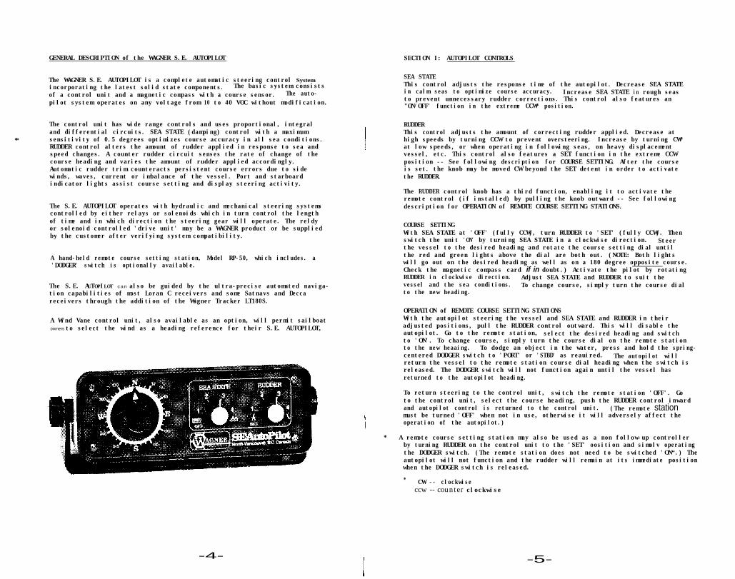
SECTION I: AUTOPILOT CONTROLS
SEA STATEThis control adjusts the response time of the autopilot. Decrease SEA STATEin calm seas to optimize course accuracy. Increase SEA STATE in rough seasto prevent unnecessary rudder corrections. This control also features an"ON/OFF' function in the extreme CCW* position.
RUDDERThis control adjusts the amount of correcting rudder applied. Decrease athigh speeds by turning CCW to prevent oversteering. Increase by turning CW*at low speeds, or when operating in following seas, on heavy displacementvessel, etc. This control also features a SET function in the extreme CCWposition -- See following description for COURSE SETTING. After the courseis set. the knob may be moved CW beyond the SET detent in order to activatethe RUDDER.
The RUDDER control knob has a third function, enabling it to activate theremote control (if installed) by pulling the knob outward -- See followingdescription for OPERATION of REMOTE COURSE SETTING STATIONS.
COURSE SETTINGWith SEA STATE at 'OFF' (fully CCW), turn RUDDER to 'SET' (fully CCW). Thenswitch the unit 'ON' by turning SEA STATE in a clockwise direction. Steerthe vessel to the desired heading and rotate the course setting dial untilthe red and green lights above the dial are both out. (NOTE: Both lightswill go out on the desired heading as well as on a 180 degree opposite course.Check the magnetic compass card if in doubt.) Activate the pilot by rotatingRUDDER in clockwise direction. Adjust SEA STATE and RUDDER to suit thevessel and the sea conditions. To change course, simply turn the course dialto the new heading.
OPERATION of REMOTE COURSE SETTING STATIONSWith the autopilot steering the vessel and SEA STATE and RUDDER in theiradjusted positions, pull the RUDDER control outward. This will disable theautopilot. Go to the remote station, select the desired heading and switchto 'ON'. To change course, simply turn the course dial on the remote stationto the new heaaing. To dodge an object in the water, press and hold the spring-centered DODGER switch to 'PORT' or 'STBD' as reauired. The autopilot willreturn the vessel to the remote station course dial heading when the switch isreleased. The DODGER switch will not function again until the vessel hasreturned to the autopilot heading.
To return steering to the control unit, switch the remote station 'OFF'. Goto the control unit, select the course heading, push the RUDDER control inwardand autopilot control is returned to the control unit. (The remote stationmust be turned 'OFF' when not in use, otherwise it will adversely affect theoperation of the autopilot.)
* A remote course setting station may also be used as a non follow-up controllerby turning RUDDER on the control unit to the 'SET' oosition and simolv operatingthe DODGER switch. (The remote station does not need to be switched 'ON“.) Theautopilot will not function and the rudder will remain at its immediate positionwhen the DODGER switch is released.
* CW -- clockwiseccw -- counter clockwise
-5-
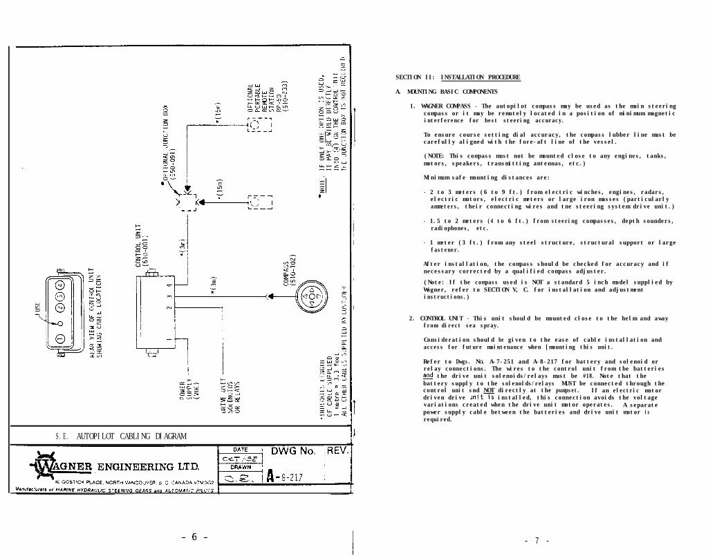
S.E. AUTOPILOT CABLING DIAGRAM
SECTION II: INSTALLATION PROCEDURE
A. MOUNTING BASIC COMPONENTS
1. WAGNER COMPASS - The autopilot compass may be used as the main steeringcompass or it may be remotely located in a position of minimum magneticinterference for best steering accuracy.
To ensure course setting dial accuracy, the compass lubber line must becarefully aligned with the fore-aft line of the vessel.
(NOTE: This compass must not be mounted close to any engines, tanks,motors, speakers, transmitting antennas, etc.)
Minimum safe mounting distances are:
- 2 to 3 meters (6 to 9 ft.) from electric winches, engines, radars,electric motors, electric meters or large iron masses (particularlyammeters, their connecting wires and tne steering system drive unit.)
- 1.5 to 2 meters (4 to 6 ft.) from steering compasses, depth sounders,radiophones, etc.
- 1 meter (3 ft.) from any steel structure, structural support or largefastener.
After installation, the compass should be checked for accuracy and ifnecessary corrected by a qualified compass adjuster.
(Note: If the compass used is NOT a standard 5 inch model supplied byWagner, refer to SECTION V, C. for installation and adjustmentinstructions.)
2. CONTROL UNIT - This unit should be mounted close to the helm and awayfrom direct sea spray.
Consideration should be given to the ease of cable installation andaccess for future maintenance when [mounting this unit.
Refer to Dwgs. NO. A-7-251 and A-8-217 for battery and solenoid orrelay connections. The wires to the control unit from the batteriesd the drive unit solenoids/relays must be #18. Note that thebattery supply to the solenolds/relays MUST be connected through thecontrol unit snd NOT directly at the pumpset. If an electric motordriven drive unit is installed, this connection avoids the voltagevariations created when the drive unit motor operates. A separatepower supply cable between the batteries and drive unit motor isrequired.
- 7 -


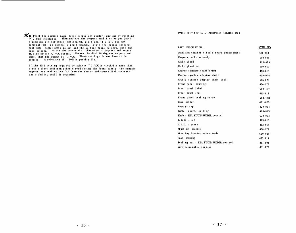
byCRV-2 full clockwise,To reset the compass gain, first remove any rudder limiting by rotating
Then measure the compass amplifier output (witha good quality voltmeter] between U4, pin 8 and +4 V Ref. (on AMPTerminal Tll, on control circuit board). Rotate the course settingdial until both lights go out and the voltage drops to zero. Note thedial setting. Rotate the course dial clockwise 20 degrees and adjustRV-1 to obtain +2 VOC output. Rotate the dial 40 degrees to port andcheck that the output is -2 VDC. These settings do not have to beprecise. A tolerance of ? 10% is permissible.
If the RV-1 setting required to achieve ? 2 VOC is clockwise more thana two o'clock position (when viewed facing the front panel), the compassmagnets are weak or too far from the sensor and course dial accuracyand stability could be degraded.
- 16 -
PARTS LIST for S.E. AUTOPILOT CONTROL UNIT
PART DESCRIPTION
Main and control circuit board subassembly
Compass cable assembly
Cable gland
Cable gland nut
Course synchro transformer
Course synchro adaptor shaft
Course synchro adaptor shaft seal
Front panel housing
Front panel label
Front panel seal
Front panel sealing screw
Fuse holder
Fuse (5 amp)
Knob - course setting
Knob - SEA STATE/RUDDER control
L.E.D. - red
L.E.D. - green
Mounting bracket
Mounting bracket screw knob
Rear housing
Sealing nut - SEA STATE/RUDDER control
Wire terminals, snap-on
- 17 -
PART NOf
550-028
550-008
610-009
610-010
470-016
650-078
615-029
650-176
660-137
615-018
603-148
421-009
420-004
620-023
620-024
303-013
303-014
650-177
620-025
655-116
211-001
431-072


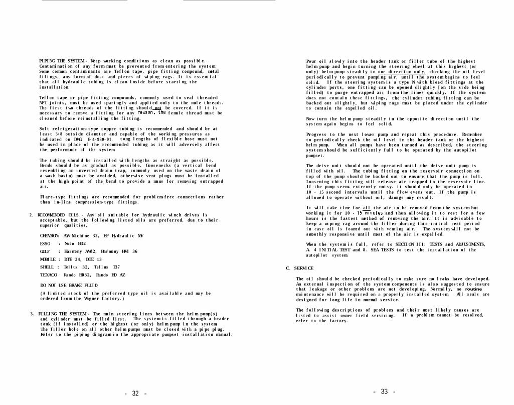
PIPING THE SYSTEM - Keep working conditions as clean as possible.Contamination of any form must be prevented from entering the system.Some common contaminants are Teflon tape, pipe fitting compound, metalfilings, any form of dust and pieces of wiping rags. It is essentialthat all hydraulic tubing is clean inside before starting theinstallation.
Teflon tape or pipe fitting compounds, commonly used to seal threadedNPT joints, must be used sparingly and applied only to the male threads.The first two threads of the fitting should not be covered. If it isnecessary to remove a fitting for any reason>he female thread must becleaned before reinstalling the fitting.
Soft refrigeration-type copper tubing is recommended and should be atleast 3/8 outside diameter and capable of the working pressures asindicated on DWG. E-4-930-01. tong lengths of flexible hose must notbe used in place of the recommended tubing as it will adversely affectthe performance of the system.
The tubing should be installed with lengths as straight as possible.Bends should be as gradual as possible. Goosenecks (a vertical bendresembling an inverted drain trap, commonly used on the waste drain ofa wash basin) must be avoided, otherwise vent plugs must be installedat the high point of the bend to provide a mans for removing entrappedair.
Flare-type fittings are recommended for problem-free connections ratherthan in-line compression-type fittings.
2. RECOMMENDED OILS - Any oil suitable for hydraulic winch drives isacceptable, but the following listed oils are preferred, due to theirsuperior qualities.
CHEVRON: AW Machine 32, EP Hydraulic MV
ESSO : Nuto H32
GULF : Harmony AW32, Harmony HVI 36
MOBILE : DTE 24, DTE 13
SHELL : Tellus 32, Tellus T37
TEXACO : Rando H032, Rando HD AZ
DO NOT USE BRAKE FLUID
(A limited stock of the preferred type oil is available and may beordered from the Wagner factory.)
3. FILLING THE SYSTEM - The main steering lines between the helm pump(s)and cylinder must be filled first. The system is filled through a headertank (if installed) or the highest (or only) helm pump in the system.The filler hole on all other helm pumps must be closed with a pipe plug.Refer to the piping diagram in the appropriate pumpset installation manual.
Pour oil slowly into the header tank or filler tube of the highesthelm pump and begin turning the steering wheel at this highest (oronly) helm pump steadily in one direction only, checking the oil levelperiodically to prevent pumping air, until the system begins to feelsolid. If the steering system is a type N with bleed fittings at thecylinder ports, one fitting can be opened slightly [on the side beingfilled) to purge entrapped air from the lines quickly. If the systemdoes not contain these fittings, the cylinder tubing fitting can bebacked out slightly, but wiping rags must be placed under the cylinderto contain the expelled oil.
Now turn the helm pump steadily in the opposite direction until thesystem again begins to feel solid.
Progress to the next lower pump and repeat this procedure. Rememberto periodically check the oil level in the header tank or the highesthelm pump. When all pumps have been turned as described, the steeringsystem should be sufficiently full to be operated by the autopilotpumpset.
The drive unit should not be operated until the drive unit pump isfilled with oil. The tubing fitting on the reservoir connection ontop of the pump should be backed out to ensure that the pump is full.Loosening this fitting will release air trapped in the reservoir line.If the pump seems extremely noisy. it should only be operated in10 - 15 second intervals until the flow evens out. If the pump isallowed to operate without oil, damage may result.
It will take time for all the air to be removed from the system butworking it for 10 - 15xnutes and then allowing it to rest for a fewhours is the fastest method of removing the air. It is advisable tokeep a wiping rag around the filler during this initial rest periodin case oil is foamed out with venting air. The system will not besmoothly responsive until most of the air is expelled.
When the system is full, refer to SECTION III: TESTS and ADJUSTMENTS,A. 4 INITIAL TEST and 8. SEA TESTS to test the installation of theautopilot system.
C. SERVICE
The oil should be checked periodically to make sure no leaks have developed.An external inspection of the system components is also suggested to ensurethat leakage or other problems are not developing. Normally, no routinemaintenance will be required on a properly installed system. All seals aredesigned for long life in normal service.
The following descriptions of problems and their most likely causes arelisted to assist owner field servicing. If a problem cannot be resolved,refer to the factory.
- 32 - - 33 -
1. If the steering wheel is stiff to turn or the pumpset will not operatethe cylinder, check the following:
a)
b)
c)
d)
e)
f)
The rudder stock for binding in its bearings.Remove the cylinder clevis pin and operate the wheel and alsothe pumpset again. If the cylinder operates, the problem is notin the steering system. If the cylinder does not move and thewheel is still hard to turn, check:
The system is free of entrapped air.
The system is piped using only the recownded copper tubing andthe two short lengths of flex hose supplied for the cylinderconnection.
The hydraulic oil is one of the types recommended, that is, notmore viscous (thicker) than automatic transmission fluid.
The copper tubing used is at least the size recommended.
The fittings on the steering cylinder are not screwed in too farand are jamming the piston rod. IF THE ROD IS SCRATCHED, IT MUSTBE REPLACED and PISTON ROD SEAL DAMAGE IS ALSO LIKELY.
2. If the steering wheel continues to turn easily and the cylinder doesnot feel like it reaches hardover or the pumpset appears to be pumping,but the cylinder is not responding, check the following:
a)
b)
c)
d)
e)
The cylinder bypass valve (if installed) has been left in tne openposition. It must be closed.
That all system fittings are tight.
The system is free of entrapped air. If air is in the system, thewheel will spring back when turned and released.
A lockvalve on another helm pump is not contaminated. This isIndicated by the wheel turning at that station. That lockvalve mustbe disassembled and cleaned. When removing the slotted inserts,take care not to lose the retained spring and steel ball or todamage the seals.
The cylinder piston seals are not damaged. All of the above shouldbe checked and determined to be satisfactory first. Remove thecylinder clevis pin and attempt to push the cylinder rod fully backand forth by hand. If the rod moves. the piston seals must bereplaced. Oil leaking along the cylinder rod from either end ofthe cylinder indicates the rod seals are defective and must bereplaced.
If there is contamination in the steering system, all components,including the nelm pumps must be disassembled and cleaned and thetubing flushed. Kerosene, Varsol or Diesel oil is suitable forthis flushing operation.
If the quality of the hydarulic oil is questionable. or waterappears to be in the system, the system oil should be replacedwith new oil from the recommended list.
3. If the pumpset operates the cylinder erratically, or the number ofwheel turns is different when turning hardover to port and hardoverto starboard, check the following:
a) The system is free of entrapped air.
b) The system is piped using only the recommended copper tubing andthe two short lengths of flex hose supplied for the cylinderconnection.
- 34 -- 35 -
40 Gostick Place,North Vancouver, B.C.Canada V7M 3G2Telephone (604) 988-l 111Telex 04-352755
Wagner-dependablesince 1937