rotating equipment snøhvit lng theory and main …folk.ntnu.no/cadorao/courses/tep10/files/rotating...
TRANSCRIPT

1
Snøhvit LNG
Rotating equipment
Theory and main boosting

2
OutlineThe LNG processRotating equipment at MelkøyaBasic theory (short)Compressors - examples–Refrigeration cycle compressors – Precooling
compressor 25-KA101–Refrigeration cycle compressors – Liquefaction
compressor 25-KA102–Refrigeration cycle compressors – Subcooling
compressor 25-KA103Pumps - example–LNG export pumps 25-PA101 A/B

3
Snøhvit LNG Statoil/Linde, MFC®
-23 °C-25 °C
-23 °C
Pre-cooling
NG
12 °C
18 bar
3 bar
8 bar
12 °C
-51 °C-55 °C
-51 °C
Liquefaction
12 °C
3 bar
19 bar
-77 °C-83 °C
-77 °C
12 °C
Sub-cooling
LNG
3 bar
54 bar
-155 °C-158 °C
-155 °C

4
Rotating equipment at MelkøyaThe rotating equipment consist of:
Gas turbinesfor power generation by converting fuel gas energy to electric power – local grid connected to Melkøya plant for backup (40 MW)
Compressorsfor pressurising gases (compressible fluids) by supplying external power
Pumpsfor pressurising liquids (incompressible fluids) by supplying external power
Turbinesfor producing power from expanding liquids or gases by converting pressure energy to work

5
Rotating equipment at Melkøya
45.8381-XY-102/201/301/401/501 Gas Turbogenerators
2.460-KA-101 A/B Air Separation Unit (ASU) Air Compressors
0.3523-KA-101 Regeneration Gas Blower
820-KA-101 Stabilizer OVHD Compressor
1224-KA-101 CO2 Compressor
16.427-KA- 101 N2/CH4 Compressor
6525-KA-103 Subcooling Cycle Compressor
3225-KA-102 Liquefaction Cycle Compressor
6525-KA-101 Precooling Cycle Compressor
Power each [MW]
Gas Turbogenerators and Compressors
Gas turbines and main compressors
6
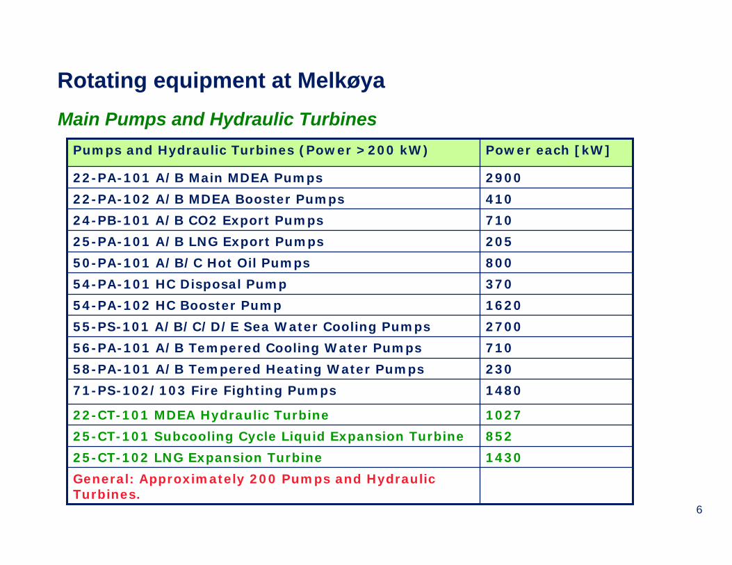
Rotating equipment at MelkøyaMain Pumps and Hydraulic Turbines
102722-CT-101 MDEA Hydraulic Turbine
270055-PS-101 A/B/C/D/E Sea Water Cooling Pumps
37054-PA-101 HC Disposal Pump
290022-PA-101 A/B Main MDEA Pumps
General: Approximately 200 Pumps and Hydraulic Turbines.
143025-CT-102 LNG Expansion Turbine
85225-CT-101 Subcooling Cycle Liquid Expansion Turbine
148071-PS-102/103 Fire Fighting Pumps
23058-PA-101 A/B Tempered Heating Water Pumps
71056-PA-101 A/B Tempered Cooling Water Pumps
162054-PA-102 HC Booster Pump
80050-PA-101 A/B/C Hot Oil Pumps
20525-PA-101 A/B LNG Export Pumps
71024-PB-101 A/B CO2 Export Pumps
41022-PA-102 A/B MDEA Booster Pumps
Power each [kW]Pumps and Hydraulic Turbines (Power >200 kW)

7
Rotodynamic compressors – Technology selection map according to GE Nuovo Pignone (Vendor for Snøhvit)
Stage Inlet flow (m3/h) Discharge pressure (bara)
1 122000 7.6 Precooling 2 138000 21.4 Liquefaction 1 125000 19.7
1 137000 18.8 Subcooling 2 25000 54.8

8
Displacement pumps
Pump power (kW)
Multistagecentrifugal pumps
Single stagecentrifugal
pumps
Propeller pumps
Conepumps
Volume flow (l/min)
Hea
d (m
wat
er c
olum
n)
Basic concepts – Pump classification chart
Head (m) is given by:
(m) gm
PHead pol
⋅=&
g is 9.81 m/s2
Pumps classification:• Head:
• Low pressure Head < 20 m
• Medium pressure20 m < Head < 60 m
• High pressureH > 60 m
• Number of stages:• Single stage• Multi stage
• Flow direction:• Radial• Axial• Cone

9
Basic thermodynamics and working fluids
In a stationary process where work (i.e. energy) is either produced or supplied, the following idealrelationship applies (power):
Work:
∫⋅=2
1
[W] p
pideal vdpmP &
p
v12
2
1
00
∫2
1
p
p
vdp
This relationship is valid for all stationary work processes and the specific work is equal to the area to the left of the curve from 1 to 2 in the figure above.
constant=⋅ nvp where n is the polytropic coefficient and is assumed constant
To be able to calculate the compression work we need a connection between p and v. This is given by the polytropic relation:
[ ] [W] 1 1122
2
1
vpvpmn
nvdpmPp
ppol ⋅−⋅⋅⋅
−=⋅= ∫ &&Inserting this relation produces
the polytropic work (power):
A special case applies to liquids as these fluids can be regarded as incompressible, i.e. the specific volume is constant (n is ± ∞):
[ ][ ] [W]
or
12
12
ppVP
ppvmP
pol
pol
−⋅=
−⋅⋅=&
&
10
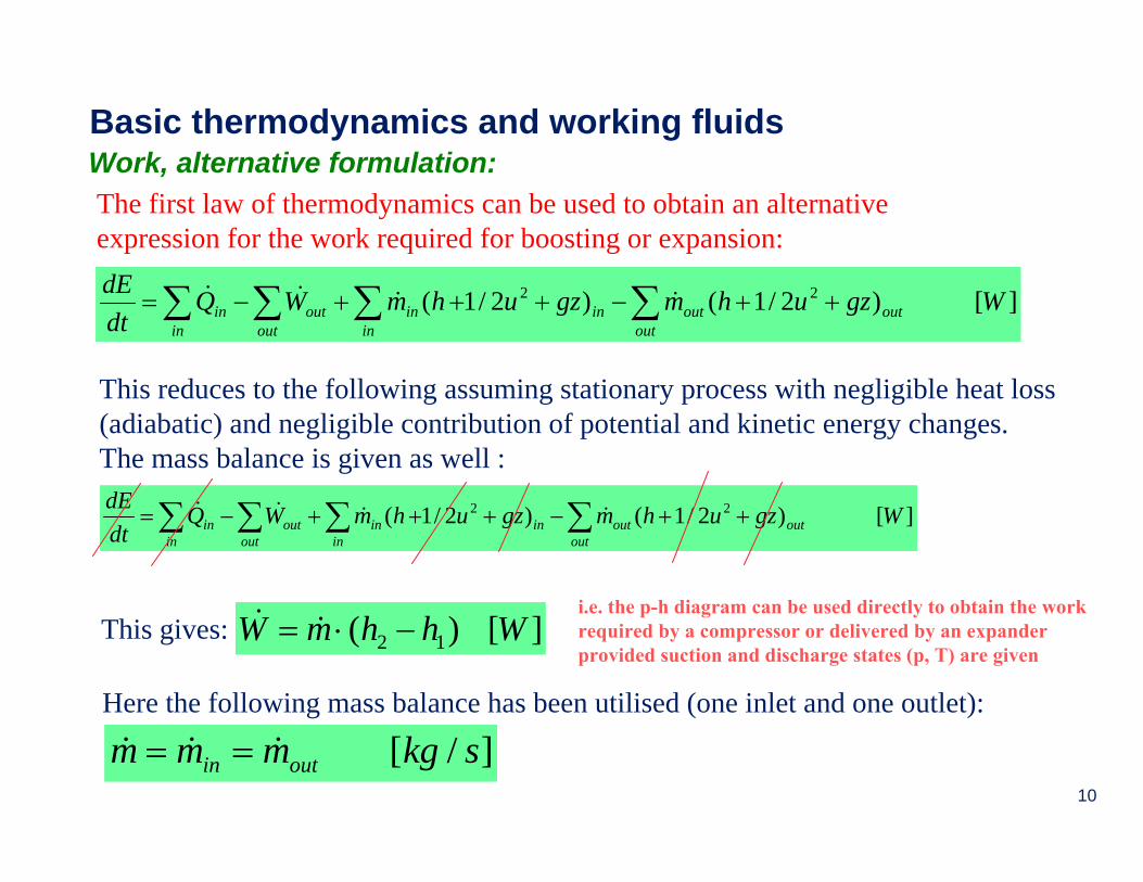
Basic thermodynamics and working fluidsWork, alternative formulation:The first law of thermodynamics can be used to obtain an alternative expression for the work required for boosting or expansion:
][)2/1()2/1( 22 WgzuhmgzuhmWQdtdE
outoutoutin
inin
outout
inin ∑∑∑∑ ++−+++−= &&&&
]/[ skgmmm outin &&& ==Here the following mass balance has been utilised (one inlet and one outlet):
This reduces to the following assuming stationary process with negligible heat loss (adiabatic) and negligible contribution of potential and kinetic energy changes. The mass balance is given as well :
][)2/1()2/1( 22 WgzuhmgzuhmWQdtdE
outoutoutin
inin
outout
inin ∑∑∑∑ ++−+++−= &&&&
][)( 12 WhhmW −⋅= &&This gives:i.e. the p-h diagram can be used directly to obtain the work required by a compressor or delivered by an expander provided suction and discharge states (p, T) are given

11
Basic thermodynamics and working fluids
Example: The liquefaction compressor at Melkøya have suction and discharge states as given in the table below. What is the power input to the compressor when the mass flow is 437093 kg/h? The polytropic coefficient n is equal to 1.2345.
114.6092-91.9372h [kJ/kg]
0.90870.9611Z [-]
0.044820.2842v [m3/kg]
79.4- 57T [oC]
19.852.029p [bar]
DischargeSuction
0.1
1
10
100
-1000 -900 -800 -700 -600 -500 -400 -300 -200 -100 0 100 200 300 400Enthalpy [kJ/kg]
Pres
sure
[bar
]
Vap/liq frac = 1.000Vap/liq frac = 0.990Vap/liq frac = 0.970Vap/liq frac = 0.950Vap/liq frac = 0.900Vap/liq frac = 0.800Vap/liq frac = 0.500Crit Point
Liquefaction - mole fraction
79.4 oC
- 57 oC
Suction state
Discharge state
The compression process is illustrated in the p-H diagram below:

12
Basic thermodynamics and working fluidsWork continued:
The work required for this compressor can now be evaluated:
Why is the results using calculation alternative 1 and 2 different from using calculation alternative 3?• Alternative 2 gives the correct work to be applied because the efficiency of the compression process is
included in the enthalpy. • Alternative 1 are based on model assuming the compression to be ideal, i.e. we have to correct the values
using the efficiency of the compression process. • Efficiency definitions will now be treated
Alternative 1: Using:
[ ] 1 1122 vpvpm
nnPpol ⋅−⋅⋅⋅−
= & [ ] MW 20 W1020 102842.0029.204482.085.193600
43709312345.1
2345.1 65 =⋅=⋅⋅−⋅⋅⋅−
=polP
We get:
Alternative 2: Using:
[ ]12 hhmP −⋅= & ( )[ ] MW 08.25 W1008.2594.916.1143600
437093 6 =⋅=−−⋅=P
We get:
13
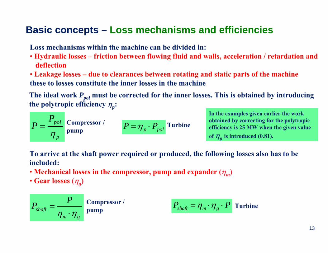
Basic concepts – Loss mechanisms and efficienciesLoss mechanisms within the machine can be divided in:• Hydraulic losses – friction between flowing fluid and walls, acceleration / retardation and
deflection• Leakage losses – due to clearances between rotating and static parts of the machinethese to losses constitute the inner losses in the machineThe ideal work Ppol must be corrected for the inner losses. This is obtained by introducing the polytropic efficiency ηp:
p
polPP
η= Compressor /
pump polp PP ⋅=η Turbine
In the examples given earlier the work obtained by correcting for the polytropic efficiency is 25 MW when the given value of ηp is introduced (0.81).
gmshaft
PPηη ⋅
= Compressor / pump PP gmshaft ⋅⋅= ηη Turbine
To arrive at the shaft power required or produced, the following losses also has to be included:• Mechanical losses in the compressor, pump and expander (ηm) • Gear losses (ηg)

14
Possible gear arrangement
System considerations – Drive, gear and couplingCompressors and pumps need a drive for supplying the power needed for compression. There are basically three different possible drives:• Electric motor (with frequency converter) – this drive is often connected to the grid to have backup in case any local power generation is shut down.
• Gas turbine – utilises local supply of fuel gas and can also, applying proper design, produce steam for process heat or expansion
• Steam turbine – provided steam is availableAll these drives have variable speed possibilities enabling fast and efficient adjustment of speed to absorb load variations
Gear: • A gear is needed provided the speed of the
drive and the compressor is not the same• This is the normal situation for compressors, the
drive has a lower speed than the compressor unless the compressors are big.
• The gear needs lube oil for bearings and / or seals.
Coupling: • A coupling is needed between the drive and the compressor / pump as they are
not usually on the same shaft.• If a gear is present, a low speed coupling is needed between the drive and the
gear and a high speed coupling is needed between the gear and the compressor / pump.• The coupling is to transmit torque, compensate for misalignment and absorb axial displacement• Couplings can be dry or oil lubricated

15
Compressor system considerations – Scrubber and coolerA scrubber is utilised upstream of compressors to:• Remove liquid droplets from the gas (compressor designed for dry gas)• Protect the compressor from liquid slugs entering the compressorThe scrubber inlet, internals and outlet are elements that are designed to facilitate separation between liquid and gas and differ between scrubber designs.
A cooler is needed to remove heat from the gas after compression due to:• material limitations and / or • process requirementsFor instance, if the gas after the compressor in the example shown earlier are to be cooled to0oC, 20 MW of heat would have to be removed.
Scrubber
Compressor
Cooler
16
Scrubber
Compressor
Cooler
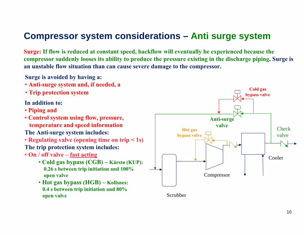
Compressor system considerations – Anti surge systemSurge: If flow is reduced at constant speed, backflow will eventually be experienced because the compressor suddenly looses its ability to produce the pressure existing in the discharge piping. Surge is an unstable flow situation than can cause severe damage to the compressor.
Surge is avoided by having a:• Anti-surge system and, if needed, a
Checkvalve
Anti-surgevalve
Cold gasbypass valve
In addition to:• Piping and• Control system using flow, pressure,
temperature and speed informationThe Anti-surge system includes:• Regulating valve (opening time on trip < 1s)The trip protection system includes:• On / off valve – fast acting
• Cold gas bypass (CGB) – Kårstø (KUP):0.26 s between trip initiation and 100% open valve
• Hot gas bypass (HGB) – Kollsnes:0.4 s between trip initiation and 80% open valve
• Trip protection system
Hot gasbypass valve

17
Pump system considerations – CavitationCavitation applies to the suction side of the pump and restrictsthe height difference between the pump inlet and the liquid level. Increased elevation decreases the suction pressure:• At a certain elevation this pressure will become lower than the
vapour pressure of the liquid• This will lead to evaporation and inherent vapour bubble
formation• The vapour bubbles follow the liquid stream• The pressure increases in the flowing direction and the bubbles
collapse when the liquid pressure is higher than the vapour pressure
The effect of this cavitation is erosion due to the impact caused by the collapsing bubbles close to the wall. The impact of these shocks will exceed the ultimate strength of the wall material and this causes wear.
Factors increasing the cavitation risk are:• Increasing liquid temperature• Increased pressure losses in the
suction pipingThis imposes restrictions on the suction height and will, at high temperature or high pressure loss, cause the suction height to be negative.
A parameter specified for pumps considering cavitation is the Net Positive Suction Head – NPSH which is the net positive head above the vapour pressure. This parameter depends on the pump design and will increase with volume flow.
18
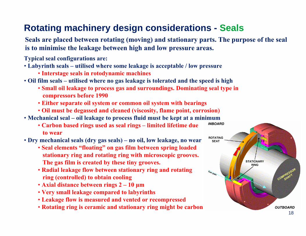
Rotating machinery design considerations - SealsSeals are placed between rotating (moving) and stationary parts. The purpose of the seal is to minimise the leakage between high and low pressure areas.Typical seal configurations are:• Labyrinth seals – utilised where some leakage is acceptable / low pressure
• Interstage seals in rotodynamic machines• Oil film seals – utilised where no gas leakage is tolerated and the speed is high
• Small oil leakage to process gas and surroundings. Dominating seal type in compressors before 1990
• Either separate oil system or common oil system with bearings• Oil must be degassed and cleaned (viscosity, flame point, corrosion)
• Mechanical seal – oil leakage to process fluid must be kept at a minimum• Carbon based rings used as seal rings – limited lifetime due
to wear• Dry mechanical seals (dry gas seals) – no oil, low leakage, no wear
• Seal elements “floating” on gas film between spring loaded stationary ring and rotating ring with microscopic grooves.The gas film is created by these tiny grooves.
• Radial leakage flow between stationary ring and rotating ring (controlled) to obtain cooling
• Axial distance between rings 2 – 10 μm• Very small leakage compared to labyrinths• Leakage flow is measured and vented or recompressed• Rotating ring is ceramic and stationary ring might be carbon
19
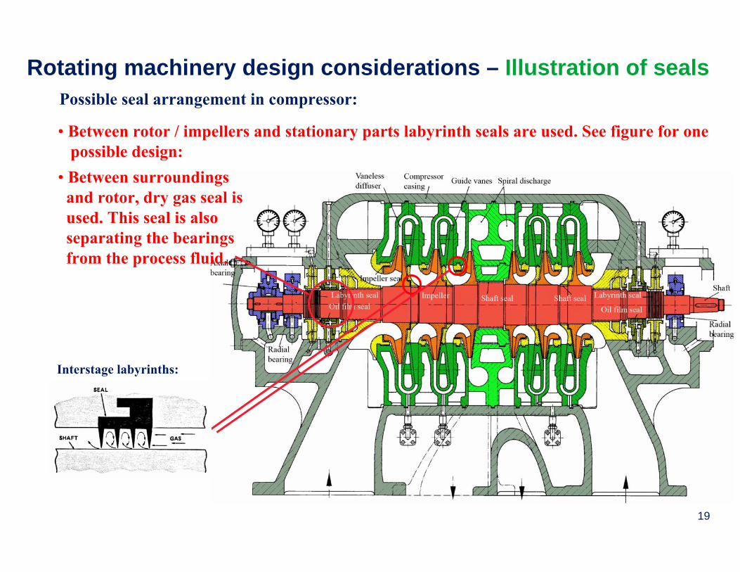
Rotating machinery design considerations – Illustration of sealsPossible seal arrangement in compressor:
• Between rotor / impellers and stationary parts labyrinth seals are used. See figure for one possible design:
Interstage labyrinths:
• Between surroundings and rotor, dry gas seal isused. This seal is also separating the bearingsfrom the process fluid.

20
Rotating machinery design considerations - Bearings / axial load balancing pistonThe axial and radial loads experienced in rotating machinery are dealt with by using axial and radial bearings. The loads are due to:• The weight of the rotor and possible load due to vibrations caused by unbalance – taken
the radial bearings, unless it is a vertical machine. As an example; a rotor running at 5000 rpm having a centre of gravity 0.1 mm away from the centreline will be exposed toa radial load that is is close to three times the load due to the weight
• The pressure difference across the machine which causes an axial force directed towards the low pressure side of the machine – taken by the axial bearing. However, usually this bearing is not capable of absorbing all the axial thrust alone (only small or low pressuremachines).
The axial balance piston / drum will take care of the axial thrust not absorbed in the axial bearing. Designed to take 70 to 80 %of the axial force. Such a system could look like this:The axial unbalance due to the pressure difference is illustrated by the arrows. B is the balance piston. Psuction
Pdischarge
21
Rotating machinery design considerations - Bearings
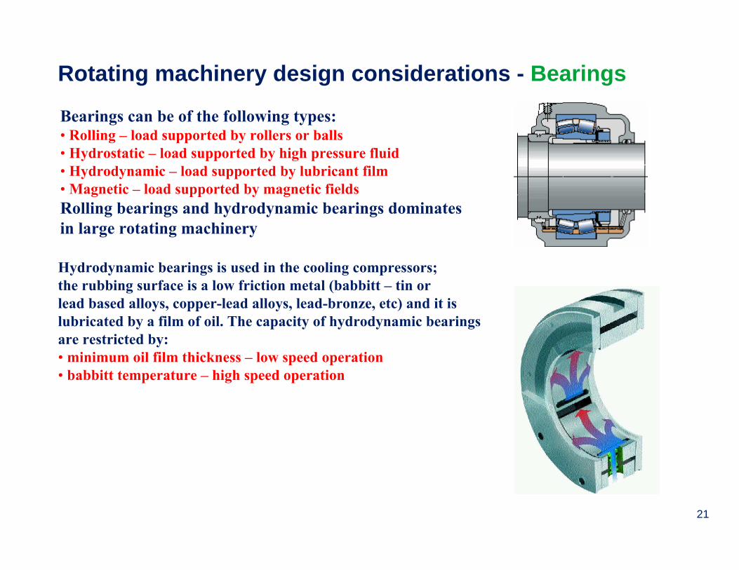
Hydrodynamic bearings is used in the cooling compressors; the rubbing surface is a low friction metal (babbitt – tin or lead based alloys, copper-lead alloys, lead-bronze, etc) and it is lubricated by a film of oil. The capacity of hydrodynamic bearings are restricted by:• minimum oil film thickness – low speed operation• babbitt temperature – high speed operation
Bearings can be of the following types:• Rolling – load supported by rollers or balls• Hydrostatic – load supported by high pressure fluid• Hydrodynamic – load supported by lubricant film• Magnetic – load supported by magnetic fieldsRolling bearings and hydrodynamic bearings dominates in large rotating machinery

22
Rotating machinery design considerations – Lube oil system
A typical lube oil system consists of:• pumps to obtain correct
pressure (depending on bearing design)
• coolers to remove frictional heat (heater also to keep the viscosity at the right level at start up)
• filters to remove particles in the oil (this is very important to obtain high regularity and availability)
• degassing tank (if the system is common with a seal oil system –not shown in the figure)
23
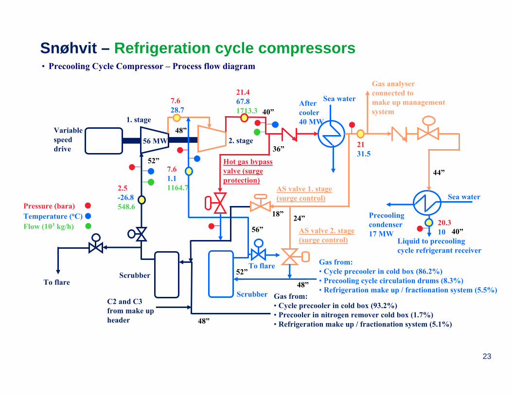
Snøhvit – Refrigeration cycle compressors• Precooling Cycle Compressor – Process flow diagram
56 MW
Scrubber
2. stage
7.61.11164.7
21.467.81713.3
To flare Gas from:• Cycle precooler in cold box (86.2%) • Precooling cycle circulation drums (8.3%)• Refrigeration make up / fractionation system (5.5%)
Scrubber
Variable speeddrive
1. stage
C2 and C3 from make upheader
7.628.7
2.5-26.8548.6
To flare
Gas from:• Cycle precooler in cold box (93.2%) • Precooler in nitrogen remover cold box (1.7%)• Refrigeration make up / fractionation system (5.1%)
Pressure (bara) Temperature (oC)Flow (103 kg/h)
52”
48”
48”
52”
56”
48”
40”
Sea water
Sea water
Gas analyserconnected to make up management system
After cooler40 MW
Precoolingcondenser 17 MW
2131.5
20.310
Liquid to precooling cycle refrigerant receiver
44”
40”
Hot gas bypass valve (surge protection)
36”
AS valve 2. stage(surge control)
AS valve 1. stage (surge control)
24”18”

24
Process
Snøhvit – Refrigeration cycle compressors• 1 x Precooling Cycle Compressor – 25-KA-101
– Vendor: GE Nuovo Pignone– Model: 3MCL1404 (Horizontally Split)
Horisontal split - typical
– # of impellers: 4– Molecular Weight: 35.148 (Ethane/Propane)– Side stream (Suction/Side stream = 1/2)– Dry Gas Tandem Seals , Vendor: John Crane, Model 28 XP
– Tilting pad bearings, Vendor: Kingsbury
– Radial bearings (2) – Flooded lubrication
– Thrust bearing – Directed lubrication– Each stage: AS control valve, opening
time < 0.5s (ESD)– Hot gas bypass valve from 2. stage to 1.
stage scrubber– Direct Drive: Electric VSDS/Siemens– Speed: 3600 RPM– Driver Rated Power: 65 MW
– Secondary seal gas: N2
– Separation gas: N2
– Primary seal gas: Process gas
25
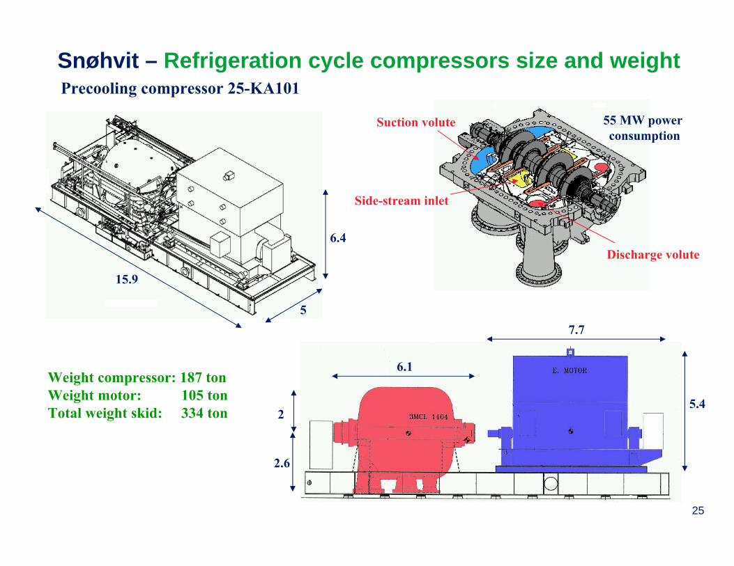
Snøhvit – Refrigeration cycle compressors size and weight
Weight compressor: 187 ton Weight motor: 105 tonTotal weight skid: 334 ton
Precooling compressor 25-KA101
15.9
6.4
5
2.6
2
6.1
7.7
5.4
Suction volute
Side-stream inlet
Discharge volute
55 MW power consumption

26
Snøhvit – Refrigeration cycle compressors• Liquefaction Cycle Compressor – Process flow diagram
Hot gas bypass valve (surge protection)
20”
AS valve(surge control)
20”
Scrubber
Variable speed drive
Compressor
C1, C2 and C3 from make upheader
19.773.5
2-57.5432.3
To flare
Gas from liquefier in cold box
Pressure (bara) Temperature (oC)Flow (103 kg/h)
27 MW
48”
52”
28”
Sea waterGas analyserconnected to make up header
After cooler16 MW
19.310
19 9.6
Gas to cycleprecooler in cold box
30”

27
Snøhvit – Refrigeration cycle compressors• 1 x Liquefaction Cycle Compressor – 25-KA-102
– Vendor: GE Nuovo Pignone– Model: MCL1406 (Horizontally Split)– # of impellers: 6– Molecular Weight: 29.88 (Methane/Ethane/Propane)– Dry Gas Tandem Seals , Vendor: John Crane Model 28 XP
Process
Horisontal split - typical
– Primary seal gas: Process gas– Secondary seal gas: N2
– Separation gas: N2
– Tilting pad bearings, Vendor: Kingsbury
– Radial bearings (2) – Flooded lubrication
– Thrust bearing – Directed lubrication– AS control valve, opening time
< 0.5s (ESD)– Hot gas bypass valve from discharge
to scrubber– Direct Drive: Electric VSDS/Siemens– Speed: 3600 RPM– Driver Rated Power: 32 MW

28
Snøhvit – Refrigeration cycle compressors size and weight
Weight compressor: 133 ton Weight motor: 58 tonTotal weight skid: 229 ton
Liquefaction compressor 25-KA102
14.4
4.4
5.6
6.7
4.6
6.1
1.5
2.5
Suction volute
Discharge volute26 MW power consumption

29
Snøhvit – Refrigeration cycle compressors size and weight
Liquefaction compressor 25-KA102

30
Snøhvit – Refrigeration cycle compressors• Subcooling Cycle Compressor - process flow diagram
Scrubber
Variablespeed drive 1. stage 2. stage
54.8102.3
18.861
2.4-78.4
To flare
Sea water
C1, C2 and N2 from make upheader
18.39.9
Inter-cooler14 MW
Gas from:• Cycle precooler in cold box (94.4%) • Main cooler in nitrogen remover cold box (5.6%)
2.6-78465.4
Pressure (bara) Temperature (oC)Flow (103 kg/h)
23 MW34 MW
48”
48”
30” 30”18”
Sea water Gas analyserconnected to make up header
After cooler 29 MW
54.411
53.610.4
Gas to cycle precooler in cold box and subcooling cycle refrigerant receiver in cold box
24”AS valve 2. stage(surge control)
24”
Recycle valve(start up)
20”Hot gas bypass valve 2. stage (surge protection)Hot gas
bypass valve 1. stage (surge protection)
20”
20”

31
Snøhvit – Refrigeration cycle compressors• 1 x Subcooling Cycle Compressor – 25-KA-103
– Vendor: GE Nuovo Pignone– Two Casings
— Stage 1: MCL1406 (Horizontally Split) - 6 impellers
Horisontal split - typical
Vertical split - typical
– Stage 2: BCL1007 (Vertically Split) - 7 impellers– Molecular Weight: 22.22 (Methane/Ethane/Nitrogen)– Dry Gas Tandem Seals , Vendor: John Crane, Model 28 XP
Process
– Primary seal gas: Process gas– Secondary seal gas: N2
– Separation gas: N2
– Tilting pad bearings, Vendor: Kingsbury
– Radial bearings (2+2) – Flooded lubrication
– Thrust bearing (1+1) – Directed lubrication– AS control valve 2. stage, opening time
< 0.5s (ESD)– Hot gas bypass valve both stages– Direct Drive: Electric VSDS/Siemens– Speed: 3600 RPM– Driver Rated Power: 65 MW
32
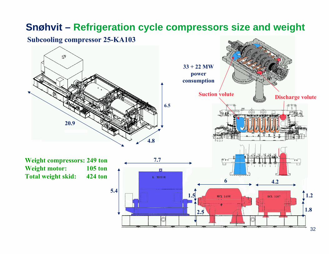
Snøhvit – Refrigeration cycle compressors size and weight
Weight compressors: 249 ton Weight motor: 105 tonTotal weight skid: 424 ton
Subcooling compressor 25-KA103
20.9
4.8
6.5
6 4.2
7.7
5.4
1.8
1.21.5
2.5
Suction volute Discharge volute
33 + 22 MW power
consumption
33
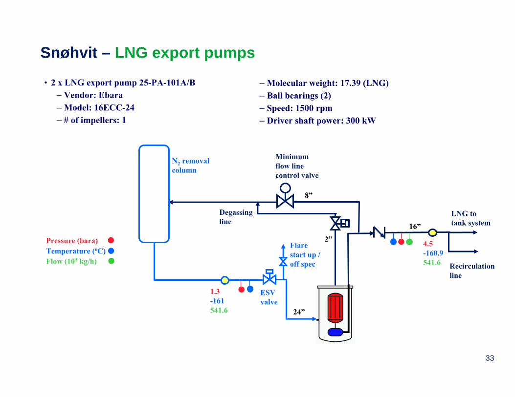
Snøhvit – LNG export pumps
• 2 x LNG export pump 25-PA-101A/B– Vendor: Ebara– Model: 16ECC-24– # of impellers: 1
– Molecular weight: 17.39 (LNG)– Ball bearings (2)– Speed: 1500 rpm– Driver shaft power: 300 kW
Minimumflow linecontrol valve
8”
Pressure (bara) Temperature (oC)Flow (103 kg/h)
1.3-161541.6
ESV valve
4.5-160.9541.6
Flare start up /off spec
N2 removalcolumn
LNG to tank system
Recirculationline
24”
16”
Degassingline
2”

34
Inlet
Outlet Snøhvit – LNG export pumps
Design:• Submerged pumps – motor and pump are
submerged in liquid inside a pressure vessel• Orientation is vertical with motor on top• Radial pump units with axial inflow• Helical inducer in inlet – allows very low NPSH• Cooling of motor and lubrication of bearings
by a small portion of the liquid being pumped• Axial load (thrust) handled by a specially designed
thrust equalizing mechanism as shown below:

35
Snøhvit – LNG export pumps size and weight
3.77 m
1.08 m
Fill / drain: 25 mm pr minute,at least 3 hours to fill vessel
Total weight: 8600 kg