rollix - kcw-drives.com
TRANSCRIPT

3
W E K E E P T H E W O R L D T U R N I N GROL L IX
90% of our production is exported to more than 40 countries, in each country.
You will find a Rollix representative or member of our distribution network at your disposal, to help with all aspects of your requirements as quickly and efficiently as possible.
Our engineering and design department will propose you innovating solutions, using the most modern software, as well as calculation by finite elements.
This catalogue specifies the shortest delivery times for standard slewing rings from our stock in France and abroad.
In order to match closely customer’s requirements Rollix has developed 2 new ranges of products: “RLX COMPACT” for applications requiring high precision and “RLX-BT” for bottling industries.
We design parts specifically adapted to your needs and we own several thousands of other references that we keep at your disposal.
Rollix specialises in preloaded slewing rings. Thanks to our process of grinding of the raceway and to systematic matching, we offer you a slewing ring that is as precise as possible throughout its lifetime.
Thanks to simultaneous engineering, we produce a product that answers the most specific requests of the most demanding customers (slewing rings made of titanium, aluminium etc...)
Your most severe requirements (loads, tightness, speed, noise etc…) are validated on our test benches.
Our ISO 9001 and ISO 14000 certification guarantees a product designed and produced according to the rule book.
Our slewing rings conform to standards DNV, LLoyd, GL etc, which are recognized worldwide.
Rollix, a department of the Defontaine group, have designed
and manufactured special bearings and slewing rings from 100
to 4500 mms diameter, with and without gear, since 1974.

4
ROLLIX
PRESENTATION OF THE COMPANY
For any further information, please contact :DEFONTAINE S.A.DEPARTEMENT ROLLIX3, Rue Louis Renault - B.P. 329FR - 44803 - SAINT-HERBLAIN CedexTel. 33 (0) 2 40 67 89 89 - Fax 33 (0) 2 40 67 89 [email protected]
R O L L I X i s r e p r e s e n t e di n t h e f o l l o w i n g c o u n t r i e s :NEW ZEALAND
NORWAYPHILIPINNES
POLANDPORTUGAL
RUSSIASLOVAKIA
SOUTH AFRICASPAIN
SWEDENSWITZERLAND
TAIWANTHAILAND
TURKEYUNITED STATES
ARGENTINAAUSTRIA
AUSTRALIABELGIUM
BRAZILCANADA
CHINACZECH REPUBLIC
DENMARKEGYPT
ESTONIAFINLAND
GERMANYGREAT BRITAIN
GREECEHONG-KONG
INDIAIRAN
IRELANDISRAEL
ITALYKOREALATVIA
LITHUANIAMALAYSIA
MEXICOMOROCCO
NETHERLANDS
WORLD-WIDE
LOCATIONS

59
65
71
75
83
90
94
100
5
1
4
5
2
3
7
212236
414244474850
51
107
CONTENTS
SLEWING RINGSSPECIAL BEARINGS
BUSINESS UNITS AND PRESENTATION
SLEWING RING SELECTIONFUNCTIONS
OTHER FEATURES
INSTALLATION AND MAINTENANCEMOUNTING STRUCTURES
INSTALLATION
MARKING
MAINTENANCE
UTIL IZATION LIMITS
PRODUCT RANGE GENERAL FEATURES
SLEWING RINGS TYPES : CATALOGUE ITEMS
CROSSED ROLLERS External Gear 06
CROSSED ROLLERS Internal Gear 07
CROSSED ROLLERS Without Gear 08
BALLS External Gear 01
BALLS Internal Gear 02
BALLS Without Gear 03
LIGHT SERIES 21 to 29
LIGHT SERIES SOLID SECTIONS 31 to 39
APPENDIXCOMMISSIONING DOCUMENTS
TECHNICAL DATA SHEET FOR SELECTION
OF A SLEWING RING
WARRANTY - AFTER-SALES SERVICE


1
7
BUSINESS UNITS AND PRESENTATION
• WIND TURBINE
• SOLAR
• MEDICAL
• PRECISION
• PUBLIC WORKS
• CRANES
• PACK AGING
• WATER TREATMENT
• OFFSHORE
• MINING
• GREEN INDUSTRY
• HANDLING
• DEFENCE
• TRANSPOR T
• INDUSTRY
• CONSTRUC TION
• CAPABILIT Y
8
BUSINESS UNIT
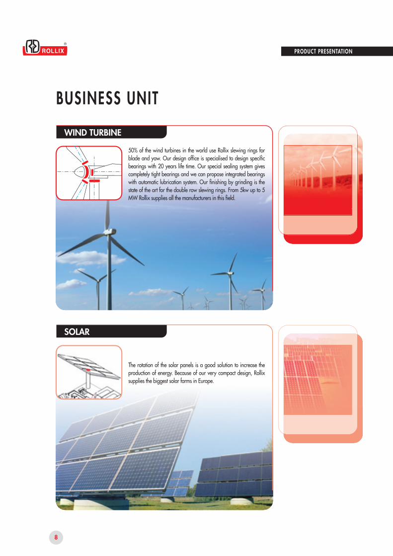
50% of the wind turbines in the world use Rollix slewing rings for blade and yaw. Our design office is specialised to design specific bearings with 20 years life time. Our special sealing system gives completely tight bearings and we can propose integrated bearings with automatic lubrication system. Our finishing by grinding is the state of the art for the double row slewing rings. From 5kw up to 5 MW Rollix supplies all the manufacturers in this field.
WIND TURBINE
The rotation of the solar panels is a good solution to increase the production of energy. Because of our very compact design, Rollix supplies the biggest solar farms in Europe.
SOLAR
PRODUCT PRESENTATION

9
1
BUSINESS UNIT
The Rollix Medical slewing rings are characterised by a high rotating speed, constant rotating torque and low noise under rotation controlled in our anecoïd room. The perfect circle and the high precision of our bearing are the result of our specific finishing and the matching of the rings and the rolling elements. We propose also innovative sealing solutions to avoid any leakage in a clean environment.
MEDICAL
The success of the Rollix slewing ring is the result of the precision of our finishing by grinding. All our production is perfectly under control and the matching of the rings and the rolling elements, gives batch after batch, the certainty to obtain the right bearing for this very demanding application. We propose also motor torque bearings. Our tailor made design follows perfectly the specific requirements of the customers. The most famous worldwide robots and machine tools manufacturers choose Rollix all around the world.
PRECISION
PRODUCT PRESENTATION

10
BUSINESS UNIT
The Rollix slewing ring, a very robust mechanical part, is particularly adapted to these applications. Our process control gives the customer a very simple solution to set up the pinion (see page 45) and to save production time. The most famous worldwide manufacturers choose Rollix for our optimised design and the quality of our service.
PUBLIC WORKS
Because of the light structure of the crane, the Rollix slewing ring is an essential and strategic part. Our design matches perfectly the life time required by the customer. The quality and the precision of our manufacturing is the key to ensure good running after many cranes dismantling. In this application the Rollix slewing ring helps construct buildings everyday all around the world with total security.
CRANES
PRODUCT PRESENTATION

11
1
BUSINESS UNIT
Large diameters and thin sections are the main characteristics of this application. These particular bearings require strict process control. The Rollix slewing rings are very well-known in the world to accept the highest rotating speed and to control the temperature during working 24 hours a day. Our quality gives a very low level of maintenance. The Rollix slewing rings manufacture millions of bottles all around the world everyday.
PACKAGING
Compared with standard bearings, the Rollix slewing ring is a good solution to reduce the assembling time, to simplify the structure and to increase the capacity of the whole system. The high capacity of our gear is the result of our process control. Many towns around the world use our product every day to treat water. Our worldwide company structure gives strong support to customers and to end users.
WATER TREATMENT
PRODUCT PRESENTATION

12
BUSINESS UNIT
High speeds, high loads and salty environment require strong and precise components. The Rollix slewing rings is the perfect answer to the offshore industry. Our specific design satisfy the main manufacturers of onboard and harbour cranes, winches, davits and rubber tired gantry cranes as well as propellers. We propose innovative solutions of sealing to completely protect the bearings from the environment. Rollix follows the international certification standards.
OFFSHORE
Stacker reclaimers, tunnel boring machines and excavators are very demanding applications. The high capacity of the Rollix slewing rings is obtained by the control of the hardening process of the raceways and the gears. Our logistic department supplies our product everywhere in the world even large diameter slewing rings.
MINING
PRODUCT PRESENTATION

13
1
BUSINESS UNIT
GREEN INDUSTRY
The stiffness of the Rollix slewing ring is a perfect solution for this type of application. Our special design gives very compact bearings, which is essential for this product. Our process control gives the customer a very simple solution to set up the pinion (see page 45) in order to save time during the mounting of the machines.
Forest and de-barker machines require strong components. The most famous worldwide manufacturers choose Rollix for our optimised design and the capacity of our slewing rings to work in a tough environment. Our finishing by grinding brings a valid pre-loading which is very important for the life time of the bearing and the comfort of the forest machine’s drivers. Our slewing rings accept the shocks and the high rotating speed of the de-barkers as well as the temperature of the coldest forests.
HANDLING
PRODUCT PRESENTATION

14
BUSINESS UNIT
The Rollix slewing ring has a strong reputation for civilian or military applications. We manufacture steel, aluminium and titanium bearings for the most demanding customers in the world. Our precision is obtained by a specific process of grinding. Our design office proposes specific solutions for all types of environments. Capacity, low torque, stiffness and high rotating speed are our main characteristics.
DEFENCE
The Rollix slewing ring permits the bogie orientation and the carriage articulation. The stress spectrum applied to these slewing rings is very specific. Our know-how answers perfectly the protection from contaminants (salt, sand, rain and mud). We can also integrate special braking devices. The Rollix slewing rings transport millions of people all around the world with train, trams and metro. We also supply slewing rings for the rotation of the truck’s wheels.
TRANSPORT
PRODUCT PRESENTATION

15
1
VARIOUS INDUSTRY
Rollix supplies slewing rings for a wide range of applications throughout the industry. Our design office will assist you to select the most effective solution price and capacity-wise. Our staff and agents worldwide will process your enquiries and provide full support to meet your customer’s requirements.
The loadsand working
conditions defined and gathered by the customer in the IT ETR 911 data sheet enables
the ROLLIX Engineering Department to select the most
suitable product.
PRODUCT PRESENTATION

16
PRODUCT PRESENTATION
CONSTRUCTIONB A S I C C O N S T R U C T I O N
Blind or through holes,untapped or tapped
Special steel, one-piece rings with or without gear
External or internal gear Lubrication holes
Filler plug
Balls or rollers made of bearing steel
Raceways
Specially designed profile seal

1
17
MPa
ZN
D3
D2
D1
1100 -
1000 -
900 -
800 -
700 -
600 -
PRODUCT PRESENTATION
M AT E R I A L S
For the slewing ring manufacture, ROLLIX selects the best material specifications to suit most foreseen usages.These materials are manufactured by approved steel works.Inspections are carried out at each significant step of manufacturing what makes it possible to warrant the quality of the products. Most of the time, we select high-grade Carbon steels which permit us to meet all operating requirements.Core hardening and tempering are carried out when the applied stresses dictate these processes.
CONSTRUCTION
Tensile strength
Nor
mal
ized
Core
har
dene
d
XC45 +42CrMo4normalized
42CrMo4 core hardened
Core hardened stateNormalized stateSTANDARD GRADES
Improved XC 45
42 Cr Mo 4
Code letter Z
code letter N
Code letter X
Code letter D

18
PRODUCT PRESENTATION
CONSTRUCTION
OTHERS MATERIALS :Specific factors of some applications or functional requirements may result in the use of materials such as : • Stainless steel.• Structural hardening steels or alloys.• Special steels for hardening undercontrolled atmosphere.
M AT E R I A L S
EQUIVALENT STANDARDS IN VARIOUS COUNTRIES :The following table shows our standard steels with the nearest equivalentforeign grades
COUNTRIES STANDARD XC45 Code Z/X 42CrMo4 Code N/D
ROLLIX selects rolling elements :balls and rollers with very specific characteristics. Their assembly requires particular caution.Any action of dismantling bearings or replacement of rolling elements is definitely inadvisable and cancels the ROLLIX warranty.
C O M P O N E N T S
GERMANY
U K
U.S.A.
ITALY
JAPAN
SPAIN
SWEDEN
AUSTRALIA
DIN
B.S.
AISI
UNI
JIS
UNE
SSSTAHL
ASA
Ck 45
080M46
16B45
C45
S45C
C45K (F1140)
1672
AS 1442-1045
42CrMo4
708M40
4142
42CrMo4
SNB7
42CrMo4 (F8232)
2244
AS 1444-4140
• Case or nitrided steel.• Special steels for very low temperature.• Aluminium-based alloys.• Titanium alloys.• Plastic, composite materials.

1
19
PRODUCT PRESENTATION
CONSTRUCTIONH E AT T R E AT M E N T S
The slewing ring transmits loads from a turning part towards the fixed part of a mechanism. The applied stresses of the rolling elements on the raceways are calculated according to the Hertz laws and the modern criteria of plasticity.ROLLIX carries out localized hardening treatments which makes it possible to satisfy these criteria just as well in terms of surface pressure as well as subsurface fatigue.In all cases, induction or flame hardening permits us to achieve the necessary hardness patterns and a sufficient depth simultaneously.In process systematic inspections during production enable us to warrant the quality and the reliability of the slewing ring treatment, according to ROLLIX specifications.According to the level of applied stresses and if geometry allows it, the same kind of hardening process may be applied on gear teeth. Our calculation models allow us to select the kind of treatment required.Other processes of local hardening may also be provided, for example : case hardening, nitriding, etc.

20
500
400
300
200
100
0500 1000 1500 2000 2500 3000
Dm
PRODUCT PRESENTATION
CAPABIL ITYT E M P E R AT U R E
The normal working temperature of the slewing rings ranges from - 25 up to + 70˚ C. Lower or higher temperatures are possible but require special design provisions by our Engineering Department.
S P E E D
The slewing rings can work whetherby oscillating motion or continuous motion. It is necessary to check thatthe circumferential raceway speed remains within the acceptable limitsof respective bearing's capacity.
E N V I R O N M E N T
In case when the working environment is particularly aggressive :• sea atmosphere,• dusty or abrasive environment (sand, coal...),particular protection devices must be incorporated such as :• labyrinths,• shields,• oil-bath.Preventive maintenance operations will be increased to ensure normal operation.
S H O C K S , V I B R AT I O N S
If the slewing rings are continously sollicited by shocks and/or vibrations, the customer must mention it in the specifications in order to design the right piece.
In any case, it is essential to consult our Engineering Department with the preciseoperating conditions.
BEARING TYPE LUBRICATION TYPE LIMITED SPEED (n. Dm)
Crossed rollers raceway
Balls type raceway
Balls type with cage
Specific design
Standard grease
Standard grease
Grease or oil
Oil or special greases
24 000 to 35 000
40 000 to 65 000
70 000 to 130 000
Consult us
Curve 1
Curve 2
Curve 3
Area 4
RPM
ROTATIONAL SPEED
Curve 1Curve 2Curve 3Area 4

2
21
•
•
SLEWING RING SELECTION
SLEWING RINGS FUNCTIONS
OTHER FEATURES

22
SLEWING RING FUNCTIONSL O A D S S E L E C T I O N
The slewing ring, being the link between a mobile element and a fixed base, must have the capacity to transmit the stresses of the mobile part towards the base. It is necessary to accurately define all the actual stresses applied so that a suitable slewing ring with adequate capacity can be selected. This should include the effects due to masses and inertias of the payloads and structures.
It is necessary to distinguish the fixed loads and the variable loads as well as the effects due to dynamic loads, the latter constituting "fatigue" stresses.The direction of forces affecting the slewing ring must be well defined so that the active tilting moment can be established.
We distinguish :
• The AXIAL LOADS whose directionis parallel to the slewing ring rotation axis. The resultant of these loads is called FA.
• The RADIAL LOADS contained inplanes perpendicular to the rotation axis. The resultant of these loads is called FR.
SLEWING RING SELECTION
AXIAL LOADS RADIAL LOADS

23
2
SLEWING RING FUNCTIONSL O A D S S E L E C T I O N
CALCULATION OF THE EQUIVALENT LOADFor the calculation, the resultant of the radial loads FR is transposed into an equivalent axial load using a factor KR as follows :
For standard slewing ring :if :FR < 0,25FA
if :
0,25 < FR < 1FA
if :FR > 1FA
• TILTING MOMENTS (bending) : in planes parallel to the rotation axis.The resulting moment working in the plane containing the rotation axis is called MT.
• SLEWING TORQUE CD controls the slewing ring rotation.
SLEWING RING SELECTION
KR = 0,5
KR = 1,5
KR = 2,4
For light series and solidsections :
The equivalent loads Feq can be obtained by the following formula :
• For the horizontally mounted slewing rings : vertical rotation axis :Feq = FA + KR . FR
• For the vertically mounted slewing rings : horizontal rotation axis :Feq = FA + 1,2 . KR . FR
KR = 3,225
TILTING MOMENT

3, Rue Louis Renault B.P. 329
F - 44803 ST HERBLAIN Cedex
Tel. 33 (0)2 40 67 89 89
Fax 33 (0)2 40 67 89 03
E-mail : [email protected]
D E S I G N D ATA S H E E T
1.1
1.2
1.3
2.1
2.2
2.3
3.1
3.2
3.3
3.4
3.5
3.6
3.7
3.8
3.9
3.10
4.1
4.2
4.3
4.4
5.1
5.2
5.3
6.1
6.2
6.3
7.1
8.1
COMPANY :
Address :
Person in charge of the project :
DESCRIPTION OF THE APPLICATION + sketch (to be attached with loads applied)
Machine / project reference :
Slewing ring position : Horiz. Vert. Other Utilisation mode : Continu. Intermittent Other
LOADS ON THE BEARING (including structural loads) : Applied Suspended
Utilisation
Axial
Radial
Moment
Rotating ring : Ext Int Speed (RPM)
Load factors applied : Excluded Included Values :
Required life :
GEAR
Geometry
Required Module
Number of teeth required
Addendum modif. factor
CRITICAL ITEMS
Classification Commission FEM LLOYDS API BV DNV Other
Specification relative to the application :
SPECIFIC REQUIREMENTS OF THE APPLICATION
Environment :
Vibrations, shocks loads :
Acceleration :
QUANTITY Yearly requirements :
REQUIRED DELIVERY TIME :
Tel. :
Fax :
Fonction :
New project : Yes No
% Time
kN
kN
kNm
Nominal Maximum Test Nominal Maximum Test
External Internal Without gear
S.R. Pinion Loads S.R. Pinion
Tangentiel load (kN)
Torque (kNm)
Dimensions Others :
Operating temperature :
Storing temperature :
Deceleration : Inert. mom./Rotation axis : Varied :
Qty per delivery :
For ROLLIX
N° Affaire :
Date :
AC VI RC
Visa :
For the USER
Name :
Date :
Signature :
Static Dynamic
IT ETR 911Document available at the Commercial Department

25
2
SLE WING RING SELEC TION
SKE TCH OF YOUR APPLICATIONSHOWING THE LOAD POSITIONS

26
SLEWING RING SELECTION
SLEWING RING FUNCTIONSB E A R I N G F U N C T I O N
The knowledge of loads and working conditions is necessary to allow us to design and dimension the "BEARING" function of the slewing ring i.e : movement type, speed, accelerations, temperatures, environment, etc.
The transmission of loads from one raceway to another varies according to the nature of applied loads.In order to calculate the ideal dimensions of the raceway, we define the load equivalent to all external efforts in the most stressed areas.These loads are corrected by factors according to the application, the usage, etc.We distinguish between :- the application factor- the usage factor- the safety factor
THE APPLICATION FACTOR KAis a coefficient taking into account the application specificity in relation to the slewing ring element.This factor is established from ROLLIX experience. It is defined in the table "APPLICATION FACTORS".
KAKUKS
THE USAGE FACTOR KUis defined according to the particular operating conditions : vibrations, shocks, occasional or accidental overloading, etc. If no other value is specified, then the nominal value is taken as 1.
THE SAFETY FACTOR KSis defined from standardized criteria for applications which must meet specific regulations such as : FEM, LLOYDS, API... This generally has the value 1,as the designer of the machine must include the regulation factors in the calculation of the loads applied on the bearing.

27
2
SLEWING RING SELECTION
SLEWING RING FUNCTIONSB E A R I N G F U N C T I O N
APPLICATION FACTORS
Armament turret
Bucket
Cable shovel
Compacter
Concrete mixer
Concrete pump
Dragline
Dock crane
Fairlead
Fork-lift truck
Fork-lift wheel
Grabbing crane
Heavy winch
Hydraulic lift platform
Hydraulic shovel
Loading dock crane
Merry-go-round
Mine digging machinery
Mobile fixed boom crane
Mobile grapple crane
1,5
1,5
2
2,5
5
1,5
1,5
1
0,8
1
1,5
1,5
2
1
2,5
1
5
1,5
1
1
1,5
1,65
1,65
1,80
2,40
1,65
1,65
1,65
1,35
1,35
1,50
1,80
1,65
1,50
2
1,65
2,40
2
1,5
1,80
Mobile telecospic crane
Offshore crane
Post jib crane
Railway crane
Rapid rotation radar
Rapid rotation scanner
Robotics
Service deck crane
Settler (water and sewage treatment)
Slow rotation radar
Slow rotation radiology
Tower crane, slewing jib type
Tower crane, slewing tower type
Track hook crane
Truck crane
Turntable
Vibrating compacter
Welding positionner
Windturbine
1
1
1
1
5
3,5
3,5
0,8
0,6
1
1
1
1
1,5
1
1
2,5
0,8
0,8
1,65
1,8
1,35
1,50
2
1,65
1,65
1,35
1,35
1,35
1,35
1,65
1,80
1,80
1,50
1,35
2
1,35
1,65
MACHINESAveragespeedRpm
Applicationsfactors
KAMACHINES
AveragespeedRpm
Applicationsfactors
KA
These factors are determinated statistically and are based on a large number of observations for each type of application.
The standard parameters retained are as follows :• Theoretical service life : 6000 hours.• Work under normal weather conditions.• Conventional application (and not specific).

28
Px
Py
O
Px
Py
O
MT
MT
SLEWING RING SELECTION
SLEWING RING FUNCTIONSB E A R I N G F U N C T I O N
Selection of the ring according to capacity
The load capacity of the slewing ring iscalculated according to its performance in function of :• its geometric envelope,• the nature of the ring materials, • the heat treatment carried out,• the nature, the number and the dimension of the rolling elements, • the contact parameters of the rolling elements.
The curve of the maximum permissiblecapacity is drawn on a graph whose Ox axis bears the equivalent axial load and the Oy axis bears the tilting moment. To simplify it, it is represented by a straight line called the "LIMIT CURVE".
Limitcurve
Feq
Feq
Service life
Many external factors have a very important influence on the service life of the bearing. Among others, we can cite :• geometric quality of supports,• structure deformation under load,• climatic conditions and environment,• quality of operating maintenance• conditions of use :repeated exposures to shocks, vibrations or sudden or intermittent movements can considerably reduce the theoretical service life.
KT = OL / OP
An estimate of the theoretical service life can be obtained by comparing the application point to the limit curve :the ratio OL/OP is called KT.
The ring size is determined by plotting the representative point of loads onto this curve. This point, called "appli-cation point" has the following coordinates :• on the horizontal axis :Px = Feq . KA . KU . KS
• on the vertical axis :Py = MT . KA . KU . KS
In any case, the application point P must be under the limit curve.
Limitcurve

29
275 00050 000
25 000
10 0007 5005 000
2 500
1 0001 1,5 2 2,5 3
2 4 6 8 10 12 14
1,2
1,0
0,8
0,6
0,4
0,2
D
KV
SLEWING RING SELECTION
SLEWING RING FUNCTIONSB E A R I N G F U N C T I O N
Service Life
An estimate of the service life D can be obtained using the opposite graph :• The curve indicates the estimated service life (hours) directly from the KT value on the horizontal axis.
Rotational speed influence
The service life D, estimated on the graph is only valid for the applications having a low rotational speed : 1 RPM.The value obtained must be multiplied by the speed factor KV indicated on the opposite graph when speeds differ from this.
D(n) = KV x D
For applications having oscillating movements, the following formula applies :
naverage = 0,60 x nreal
RPM
SERVICE FACTOR
SPEED FACTOR

30
8.8
10.9
12.9
800
1040
1220
640
940
1100
40
40
40
SLEWING RING SELECTION
SLEWING RING FUNCTIONSFA S T E N I N G F U N C T I O N
Minimal mechanical characteristics (according to ISO)
In order to transmit the loads previously defined, it is necessary to realize an adequate mechanical fastening of the bearing on the associated frames, thus forming rigid connection of the ring and its supports.While several fastening methods are feasible, the most efficient one remains the use of screws and nuts.Welding operations are absolutely prohibited.The slewing ring proper functioning and the application safety are dependent on the correct bolting definition and fastening method during installation, complying with our workmanship.
External hexagon head screws must be preferred to cap screws (internal hexagon) whenever possible.ROLLIX recommendation : screws and nuts, with guaranted mechanical properties, matched, prelubricated so as to obtain a known and permanent screw/nut friction factor. The surface coating on the bolts must not generate any embrittlement.
GRADE TENSILE (MPa) YIELD (MPa) FATIGUE (MPa)
BOLTS QUALITYThe ISO 898-1 standards define the bolting grade adapted to structure assemblies such as slewing rings.ROLLIX recommends the use of HIGH TENSILE bolts grade 10.9 and exceptionally grade 8.8 or 12.9 with rolled threads after heat treat.
The nuts must be of a same or highergrade as the associated screw. For a screw diameter d, a nut height of 1.d is recommended.
For rings in normalized steel Z or N,the use of hardened flat washers is required.Minimal properties should be :• a yield strength greater than or equal to 600 Mpa,• a diameter : DR = 2 d,• a thickness : h > 0,3 d
Exceptional
Recommended
Exceptional

31
2
d
L K
L K
FA
FA
SLEWING RING SELECTION
SLEWING RING FUNCTIONSFA S T E N I N G F U N C T I O N
BOLTING CALCULATIONThe ROLLIX calculation formulae take into account the current standards and regulations as well as the many research and experimental findings.These calculations are mainly inspired by the AFNOR FD E 25.030, the recommendation VDI 2230 (1988) and the standard API 2C (1995).
Supported loads must be distinguished from hanging (suspended) loads acting in tension.Consult ROLLIX, in the case of hanging (suspended) loads .
Standard calculation hypotheses
• Supported loads acting incompression.• Equispaced bolts ; i.e equally positioned on the pitch circles.• Steel rings and supports.• Supports complying with our instructions : thickness, stiffness, surface eveness (see chapter STRUCTURES page 42).• Rings bolted directly onto its supports.• In cases of heavy radial loads, we recommend to use pilots or to glue so that bolts will not be subjected to shear stresses.• The clamping length must be at least equal to five times the diameter : LK > 5.d.
HANGING LOAD
SUPPORTED LOAD

2 3 4 5 6 7 8
2,75
2,50
2,25
2,00
1,75
1,50
1,25
1,00
33
d
30
27242220161412
32
Fk
Lk/d
SLEWING RING SELECTION
SLEWING RING FUNCTIONSFA S T E N I N G F U N C T I O N S
Calculation of the number of boltsWhen the ring has been previously selected according to its utilization and its load capacity, the bolting is then determined to correspond to the bearing capacity. The calculation of the minimum number of fasteners is carried out according to the following formula for the most unfavourable load case. In any case, a sufficient number of bolts ensuring an effective connection between ring and support frames must be kept, in order to avoid any ring deformation.
N = 1,6 . FK ( 4 . MT - FA . Df )Df ( Ts - Fpc )
where :N = Number of bolts theoretically necessary.1,6 = Tightening factor (assembly error factor) for torque wrench Grade B according to FD E 25-030.Fk = Bolt stretch factor, see sketch.MT = Total tilting moment applied to the ring in kNm.FA = Axial load in kN.Df = Fastener pitch circle diameter in m.Ts = Tightening tension.d = Bolt diameter in mm.Ø m = Raceway mean diameter in m.
Fpc = Loss of tension due to embedding in kN, see graph.Lk = Clamping length in mm.
Bolt stretch factor FkThis factor takes the assembly geometry into account. It is based on the bolt diameter and the ratio of clamping length to diameter.The best fastening is obtained with through-holes in the ring and the supports : by using screws and nuts, the clamping length is long, bolt stiffness is satisfactory and tension losses are minimised.In case of screw fastening into tapped holes, the setting depth must not be less than 1.25.d.
BOLT STRETCH FACTOR

2
8
7
6
5
4
3
2
1
333027242220161412
2 4 6 8 10
33
Fpc
Di
Db
dw
d
Lk/d
d
SLEWING RING SELECTION
SLEWING RING FUNCTIONSFA S T E N I N G F U N C T I O N S
Tightening tension : TsTightening tension of fastening bolts must be sufficient to warrant theabsence of looseness which is essential to ensure the resistance of the assembly fatigue.
Calculation of the minimum fastenerpreload :It is useful to check that the standar-dized preload of the chosen bolt
Loss of tension :During tightening and under external loads, peening of the surface roughness of the contact parts occurs, reducing the initial bolts elongation and thus producing a loss of tension, which
12
56
14
77
16
106
22
208
24
239
27
315
30
385
33
480
20
166
Diameter (mm)
Tension (kN)
diameter is sufficient compared to the dynamic stresses imposed when operating.
Ts > ( 2,25 )[( 4.MT )-FA+80 N.d.10-3]N Ø m
The standardized tightening tension at80% of Re must be selected from the following table according to the chosen bolt diameter : bolting grade 10.9.
decreases the preload in the assembly.This loss of tension has been tabulated on the following graph which shows values in function of diameter d and the ratio Lk/d.
Calculation of under head contact pressure :Usually, this calculation is not required when treated flat washers are used. It is however recommended when cap screws are used. (Chc).
We must have :
FB max < P admAc
withFB max = Ts + 0,13.FE
with
FE = ( 1 ) [ ( 4.MT ) - FA ]N Ø m
and
Ac = ( π ) ( dw2 - Di2 )4
400 MPa
620 MPa
270 MPa
Allowable pressure :
for steels N and Z
for steels D and X
for steels type E36
IMPORTANT REMARKThe use of elastic washers whateverthe type or model is absolutely pro-hibited and will void all warranty.
LOSS OF TENSION

34
20 40 60 80 100 120 140 160 180
2,0
1,8
1,6
1,4
1,2
1,0
0,8
0,6
0,4
0,2
0
0,2
0,4
0,6
0,8
Z1+Z2
SLEWING RING FUNCTIONSS L E W I N G F U N C T I O N
RESISTANCEOur rating graphs indicate the values of allowable maximum tangential force in fatigue T.The continuous operating capacity is obtained by the application of a suitable load moderating factor.
T = 2 CD DrefCd = Torque on gearDref = Reference diameterUnless otherwise stated, the indicated values are valid for geared rings made of normalized steel XC45 : code Z. When these values are not sufficient, ROLLIX can proceed with contour hardening which considerably improves the resistance to tooth root bending and the resistance to contact pressure. For very heavy loading conditions, ROLLIX carries out complete hardening of the tooth and of its root in the wheel rim. When only a better wear resistance is required, surface hardening of tooth flanks only is possible.
ROLLIX slewing rings generally incorporate a SLEWING mechanism to control rotation of the mobile part. This function can be achieved by various means :
gear drive (the most frequent case)
belt drive
chain drive
direct drive
GEAR DRIVEInvolute teeth, spur or helical are directly cut into the outer or inner ring (spur gear only).
GEOMETRYMost of the ROLLIX bearings have a gear improved by positive addendum modification which notably decreases pressures as well as by a truncation avoiding teeth root interference at the pinion.It is also essential to make a positive addendum modification on the pinion teeth, in order to avoid the geometric interference which appears under18 teeth.Furthermore, the drive stresses induce shaft bending and gear deformation which are harmful to good meshing.To prevent these faults, we recommend profile corrections be carried out on the pinions : i.e.crowning and tip relief. Our Engineering Department will assist upon request.
1
2
3
4
upper limit
maximum Henriot recommended value
minimum value
SPECIAL CASES
BETTER BENDING STRENGTH
BETTER DRIVE
lower limit
addendummodification
SLEWING RING SELECTION
PROFILE ADDENDUM MODIFICATIONS

35
2
SLEWING RING FUNCTIONSS L E W I N G F U N C T I O N
Maximumdiameter
MaximummoduleDIN class AFNOR class Options
12
10-11-12
9-10
7-8
12
11-10-9
8-9
7
all sizes
all sizes
3100
2500
25
20
22
20
SUPERFICIALLY HARDENED GEAR• Generally, by contour hardening to 55 HRc (± 5).
• The gear classes stated above are offset and ROLLIX can meet AFNOR or DIN standards for grades 11-12.
When a higher gear quality such as grade 5 or 6 is needed, gear grinding becomes necessary (ask our Engineering department).
WITHOUT SUPERFICIAL HEAT TREATMENT
IMPORTANTROLLIX considers that the relevant gear characterizing parameters for each quality class defined by AFNOR, DIN or ISO must be met. In case a customer does not require all of the parameters and needs to meet only one or two of them, ROLLIX can achieve higher qualities.
Module 45 with special tooling
Specific equipment necessary
• made upon request
SLEWING RING SELECTION
GEAR QUALITYUnless stated otherwise, ROLLIX manufactures slewing ring gears according to AFNOR or DIN standards which meet the following criteria :

36
X
X
SLEWING RING SELECTION
OTHER FEATURESP R E C I S I O N - T O L E R A N C E S
Standard ring tolerances are generally defined according to ISO 286-1 and 2 standards.For applications requiring a higher precision level : robotics, radars, etc.a better grade is considered. The tole- rance values are then indicated on the bearing drawing. For bearings of large diameter with thin cross sections where radial stiffness is low, the tolerance values must be considered when bearing is assembled to its supports, these ensuring proper circularity.
GEOMETRYThe selected criteria are : • For the diameters : Js 13• For the centeringsBores : H9Shafts : f9• For the overall height : ± 1 mm
FASTENINGThe bolt circle diameters are machined to tolerance Js10 with a minimumof ± 0,2 mm.
GENERAL TOLERANCES TABLE (ACCORDING TO ISO 286-2)
GEARThe value of the total run-out is indicated in the drawing title block. The measurement and tolerance over K teeth are also indicated on the drawing.This dimension includes the contribution of the ring to the meshing backlash.
BEARING• The AXIAL RUN-OUT of the supporting faces is measured using a dial gauge over one full revolution (see opposite sketch).
fromto
180250
+115
- 50- 165
± 92
± 0,36
250315
+ 130
- 56- 185
± 105
± 0,405
315400
+140
- 62- 202
± 115
± 0,445
400500
+155
- 68- 223
± 125
± 0,485
500630
+175
- 76- 251
± 140
± 0,55
630800
+200
- 80- 280
± 160
± 0,625
8001000
+230
- 86- 316
± 180
± 0,70
10001250
+260
- 98- 358
± 210
± 0,825
12501600
+310
- 110- 420
± 250
± 0,975
16002000
+370
- 120- 490
± 300
± 1,15
20002500
+440
- 130- 570
± 350
± 1,4
25003150
+540
- 145- 685
± 430
± 1,65
Diameter(in mm)
Pilot H9(in μm)
Spigot f9(in μm)
Diameter Js10(in μm)
Diameter Js13(in mm)

37
2
0,80
0,70
0,60
0,50
0,40
0,30
0,20
0,10
500 1000 1500 2000 2500 3000
YY
mm
F
SLEWING RING SELECTION
OTHER FEATURESP R E C I S I O N - T O L E R A N C E S
• THE RADIAL RUN-OUT of the spigots is also measured by rotation (following sketch).
These measurements are carried out by placing the magnetic base of a dial gauge on the fixed ring, while the filler is taken in contact with the element to be measured. The reading will be obtained during one rotation of the turning ring (value T.I.R).
• THE DEFLECTION UNDER MASTER LOAD is measured as follows :One of the bearing ring is fastened to a rigid support and a master load F is applied axially on the other ring to a point closely located to the raceway.The deflection under load F is measured using a dial gauge whose base is attached to the other ring.The deflection under standard load of every slewing ring is measured at the factory.This value is compared to the allowable limits, and is registered.
Raceway meanØ in mm
Maximum value T.I.R.
Radial Run-out
Axial Run-out
mm
DEFLECTION UNDER MASTER LOAD
38
SLEWING RING SELECTION
OTHER FEATURESS L E W I N G T O R Q U E
Calculation of the necessary torque to enable a rotation of the whole assembly takes into account :• loads on the machine,• rotating masses,• distance of these masses to the rotation axis,• speeds and accelerations,• resisting torques.
Two types of torques are distinguished :
Start up slewing torque : Cd = Crv + Crc
Acceleration slewing torque : Cg = Crv + Crc + Ca
Crv = Friction torque of unloaded bearing
Crc = Rotating torque due to loads
Ca = Acceleration torque
Cd = Starting torque
All these torques are expressed in kNm.
Crc : ROTATION TORQUE DUE TO LOADS
The starting torque required takes into consideration loads on the bearing and friction of the components.
Balls type slewing ring
Crc = [ 13,11 MT + 3 FA + 11,34 FR ] Ø m . 10-3
Ø m
Crossed rollers type slewing ring :
Crc = [ 15,3 MT + 3,75 FA + 8,19 FR ] Ø m . 10-3
Ø m
MT = Resulting moment in kNm
Ø m = Raceway mean Ø in meters
FA = Axial load in kN
FR = Radial load in kN
Ca : ACCELERATION TORQUE
The torque needed to accelerate the loads from the initialspeed up to the final speed, during time (t) is defined by :
Ca = π . n . I . 10-3
30 . t
t = Acceleration time in sec.n = Speed variation in RPM
(Final speed - Initial speed)I = Moment of inertia of the machine in Kg . m2
I = I1 + I2 + I3 + ..... In
where I1 à In = moments of inertia of the moving loads with regard to the rotation axis expressed in Kg . m2.
Generally we have :I1 = G1 x r 12
In = Gn x r n2
G1 to Gn = Mass of various rotating componentsexpressed in Kg.
r 1 to r n = Distances between the loads centre ofgravity and the ring rotation axis expressedin meters.
Note : The resisting torque depends on the support surfaceflatness and lubrication.

39
2
1,5
1
0,5
0,5 1 1,5 2 2,5 3
2
1,5 m
6800 kg500 kg
SLEWING RING SELECTION
OTHER FEATURESS L E W I N G T O R Q U E
LOADS APPLIED ON THE RING
Axial FA : 68 kN + 5 kN = 73 kNRadial FR : 0,29 kN, negligibleMoment MT : 5 kN x 1,5 m = 7,5 kNm
SLEWING TORQUE : Raceway mean Ø = 2 metersCrv : according to the graph : 1 kNm
Crc = [ 13,11 x 7,5 + (73 x 3) + (11,34 x 0)] 2.10-3
2
Crc = 0,536 kNm
Slewing torque at start upCd = 1 + 0,536 = 1,536 kNm
Platform moment of inertia :
MR2 = 6800 x 22 = 13600 Kg m2
2 2
Cube moment of inertia :Mr2 = 500 x 1,52 = 1125 Kg m2
Total moment of inertia :13600 + 1125 = 14725 Kg m2
Acceleration torque :n = 6 - 2 = 4 RPM
Acceleration time : 20 sec
Ca = 14725 x π x 4 10-3 = 0,3084 kNm30 x 20
Slewing torque during accelerationCg = 1 + 0,536 + 0,3084 = 1,845 kNm
APPLICATION EXAMPLE
Platform diameter : 4 m.Platform mass : 6800 kgCube mass : 500 kgBall type slewing ringraceway mean Ø : 2 m.Distance from the cube to the rotation axis : 1,5 m.Initial speed : 2 RPMFinal speed : 6 RPMAcceleration time : 20 sec.
Unloaded frictiontorque resistance in kNm
Standard slewing rings having 2 seals
Light series slewing ringswith 2 seals Raceway
mean Ø in m
The friction torque of standard slewing rings is defined in the following graph.ROLLIX, upon request, can supply slewing rings with lower or higher torque values.

40
SLEWING RING SELECTION
OTHER FEATURESP R O T E C T I O N
SEAL RANGE TABLE
Operating conditions Ranges
SEALS
ROLLIX slewing rings are generallyequipped with protecting seals on both sides of the raceway.These seals have the function of : • protecting raceways against small-sized contaminating agents,• retaining the lubricant in the raceway.For specific requirements, ROLLIX designs suitable protective devices,such as :• standard and specific seals,• lip seals• combination of two or more seals.
SHROUDS
For severe application conditions andin order to limit the effects of aggressive agents such as :• swarf and metal chips• welding grains• abrasives• mud• sand • water and heavy sea splashes• cutting fluids...
ROLLIX strongly recommends to install effective protective shields.Furthermore, during cleaning with solvents or pressurised water, it is advisable to avoid working in the protective device area.
SURVEY
If, during regreasing, large grease discharges are noticed, it is advisable to check :• that seal is still correctly positioned,• that seal is not damaged (cut, torn, worn),• that seals are still capable for proper bearing operation.Therefore, this seal can either be reinstalled or replaced.
For particular applications, ROLLIX suggests a protective surface treatment, such as :
P R O T E C T I V ES U R FA C E C O AT I N G
1
2
3
4
5
Zinc plating (+ chromate coating)
Phosphate coating
Chemical nickel plating
Paint
to 9 Miscellaneous treatments,for example, chrome plating, Schoop's metal spraying process, anodic oxidization, etc.
Consult us.

41
3
•
•
•
•
•
INSTALLATION AND MAINTENANCE
MOUNTING STRUCTURES
INSTALLATION
MARKING
MAINTENANCE
UTIL IZATION L IMITS

42
RING INSTALLATION
STRUCTURESS U P P O R T S T R U C T U R E S
500
25
750
30
1000
35
1250
40
1500
50
2000
60
2500
70
3000
80
SHAPE TOLERANCES
Shape defects of the supports lead todeformations of the raceway. This can cause tight spots or possible seizure and will reduce the bearing service life. The maximum flatness defects must not exceed the values of the opposite table.
CHASSIS DESIGN
The slewing ring has a moderate axialstiffness : the diameter is large compared to the cross section. It must be mounted on a machined supporting base, ensuring sufficient stiffness with regard to the loads to be transmitted. This makes it possible to ensure an even distribution of stresses and to avoid any deformation during operation, which would be harmful to the good working of the ring.
Therefore, it is necessary to use supporting bases with a minimum thickness not less than the values indicated in the table above.The width of the supporting surfaces is to be at least equal to that of the ring.
We recommend structural reinforcements in a circular frame placed directly beneath the raceway. For better loading uniformity, thick circular frames are preferred to thin reinforcements with ribs.
Raceway meandiameter (mm)
Minimumthickness (mm)
500
0,10
0,12
750
0,12
0,18
1000
0,15
0,21
1250
0,18
0,25
1500
0,20
0,28
2000
0,25
0,33
2500
0,29
0,38
3000
0,32
0,42
Raceway mean diameter (mm)
Maximum toleranceCrossed Roller (mm)
Maximum toleranceBalls (mm)

43
3
δ
δ4
RING INSTALLATION
PLASTIC CEMENTS
If the above tolerances could not bemet, then Epoxy-type resins can beused instead of finish-machining of the surfaces.
Several products are possible depending on the dimensions and the amount of out of flatness to be compensated. Detailed instructions are available from our Sales Department.
STRUCTURES
STIFFNESS TOLERANCES
The stiffness of the supporting framesmust be such that deflections do not exceed the values of the opposite table under maximum load.
S U P P O R T S T R U C T U R E S
These maximum values are allowable for "long waves" in the circumferential direction."Short waves" for example between two fastening holes, must not exceed 1/4 of the values in the opposite table.Waves in the radial direction (conicity) must be less than 0,05 mm / m of raceway mean Ø.
Raceway meandiameter (mm)
Maximumdeflection (mm)
500
0,25
750
0,30
1000
0,35
1250
0,45
1500
0,55
2000
0,65
2500
0,80
3000
1,00
LONG WAVES
SHORT WAVES
44
RING INSTALLATION
INSTALLATION
Our slewing rings are carefully packed in order to avoid any damage during transport.Transport and storage are to be carried out in horizontal position only ; transport in other positions requires special methods.As with any mechanical precision part, the rings must be handled with care avoiding any shocks, particularly along the radial axis.Handling should be carried out with suitable equipment for the weight of the part, which is indicated on the identification tag.
TRANSPORT - HANDLING
DELIVERY - STORAGE
The packed rings have an anticorrosive surface protection allowing a6-month-storage in a covered and temperate room.A suitable protection must be applied for longer storage.It is necessary to regrease after each 18-month-period (see paragraph MAINTENANCE - LUBRICATION).
UNPACKING - PREPARATION INSTALLATION
WHEN INSTALLING THE BEARING :
Structure
• Make sure that supporting structurescomply with specifications (see chapter STRUCTURES).• Check for chips, weld seam particles, corrosion signs, etc.• Check the good mating of the rings on the supports.
SPIGOTS
When loads along the radial axis areimportant, especially when the bearing is placed vertically, it is then mandatory to use the centerings provided for that purpose.The intercalative structural adhesive type LOCTITE 586 provides a good means to limit the relative displace-ments between rings and supports.See our technical instructionsIT ETR 521, available upon request.
POSITIONING
The hardening junction which ismarked by a red line on the geared ring, and located at the filler plug on the other ring, must be placed at 90˚ to the main load axis or to the arm supporting the load (see chapter MARKING).
When unwrapping the bearing :• Take care not to cut the protective seals when removing the packing paper.• Cut this paper, preferably on the external diameter, and not on the upper or lower faces.
When degreasing the bearing :• Use a standard commercially available solvent. Chlorine containing solvents are prohibited.• Take care not to introduce any solvent under the seals or in the raceways.• Before fitting the grease nipples or junction pipes, remove the plastic caps or the Hc screws from the greasing holes.

45
3
107
4
1
8
9
12
5
2
6
3
11
INSTALLATIONINSTALLATION
RING INSTALLATION
STAR-SHAPED TIGHTENING
TIGHTENING TORQUE
12
117
14
185
16
280
20
560
22
750
24
960
27
1400
30
1900
33
2600
10
69
18
390
Diameter (mm)
Torque (N.m)
Checking the gear backlash
WHEN INSTALLING THE PINION :
Gear
• The pinion should be located approximately at 90° of the major loading axis.
• Adjust the driving pinion to themaximum eccentric point of the ring gear, marked by a blue line.• At this stage, the backlash must be within the limits of the calculated values or minimum at 0,05 x module.• When several pinions are used, each one must be adjusted to the same conditions.• During tests, make sure that good alignment of the pinion and of the slewing ring axes permits a satisfactory contact across all the gear width.• Before running, lubricate the teeth of the slewing ring gear and of the pinion (see chapter MAINTENANCE).
Fastening
• Check that fasteners are really of therecommended grade, e.g. marked 10.9 on the head and that threads are properly lubricated.• For bearings in normalized steel Z or N, the use of treated hardened flat washers is required as follows :• the yield strength is greater than or equal to 600 Mpa,• the diameter DR = 2 d,• the thickness h > 0,3 d.The elastic washers type Belleville, Grower or others of whatever type or
pattern are absolutely prohibited andwill void all warranty.• Install all fasteners and tighten lightly.• Then tighten to the specified value using a properly calibrated torque wrench ; hydraulic devices are advisable.• Use a "star shape" pattern whentorquing which ensures a uniform tightening over the whole periphery.The tightening torque to be applied is defined in the following table for bolt grade 10.9 and a screw/nut friction factor of 0,12 according to VDI 2230.
backlash

46
RING INSTALLATION
INSTALLATIONINSTALLATION
Tests - inspections
After final tightening of all fasteners :• Rotate the ring for at least 3 turns.• Recheck the backlash value on the gear mesh over one full revolution.• Measure the total deflection under a known load. The checked points should be marked.It is advisable to register these values in a maintenance logbook specific to the machine, see our "COMMISSIONNING DOCUMENTS" ref. IT-DTR.19.005.
Operating process :
• Place a measuring device betweenthe two rings as close as possible tothe raceway on the main load axis : precision grade 0,1 mm minimum.• Calibrate to zero, under a known load.• Apply a measured load.• Read the deflection value at the point considered.• Repeat this measurement in the previously marked points.• Take into account the deflection ofthe support chassis and the fasteners elongation corresponding to the instrument position.
Measuring device
DEFLECTION MEASUREMENT UNDER LOAD ON MOUNTED SLEWING RING
47
3
M A D E I N F R A N C E
GROUPE DEFONTAINE
0 6 1 1 1 6 0 0 Z Z 1 2 A0 6 1 1 1 6 0 0 Z Z 1 2 A
03/1996
N° 1996 330 Kg
MARKING
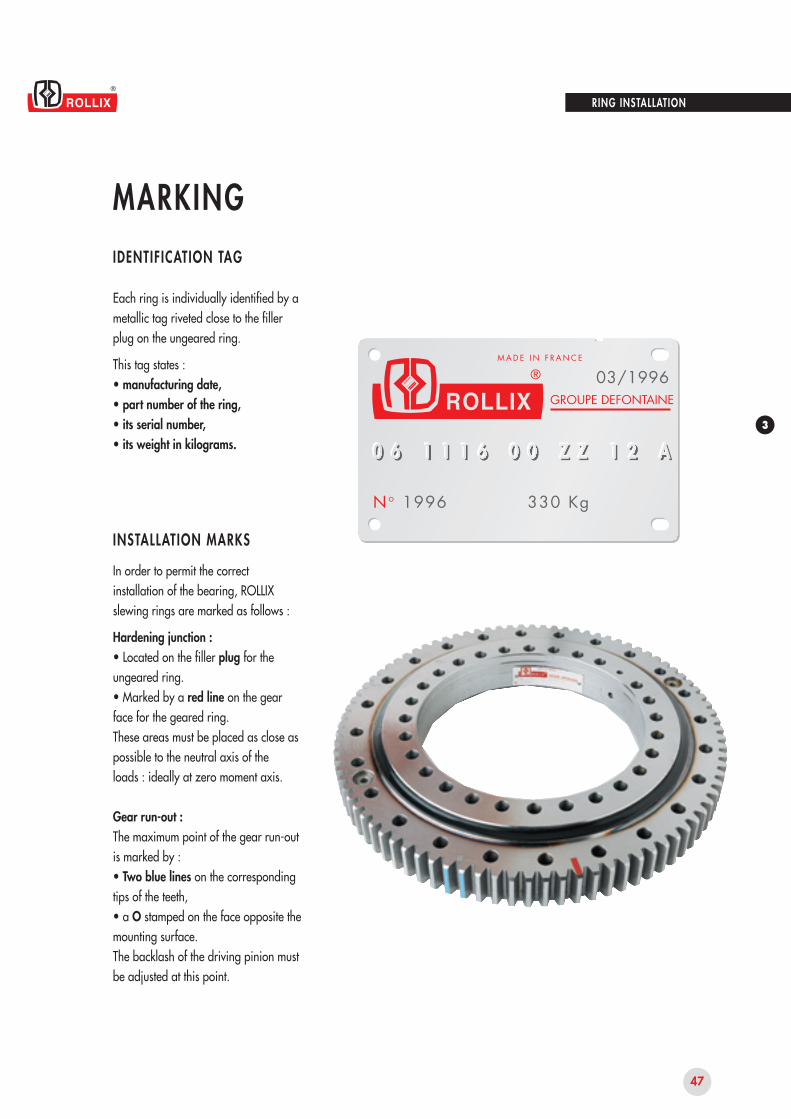
Each ring is individually identified by a metallic tag riveted close to the filler plug on the ungeared ring.
This tag states :• manufacturing date,• part number of the ring,• its serial number,• its weight in kilograms.
IDENTIFICATION TAG
INSTALLATION MARKS
In order to permit the correct installation of the bearing, ROLLIX slewing rings are marked as follows :
Hardening junction :• Located on the filler plug for the ungeared ring.• Marked by a red line on the gear face for the geared ring.These areas must be placed as close as possible to the neutral axis of theloads : ideally at zero moment axis.
Gear run-out :The maximum point of the gear run-out is marked by :• Two blue lines on the corresponding tips of the teeth,• a O stamped on the face opposite the mounting surface.The backlash of the driving pinion must be adjusted at this point.
RING INSTALLATION

48
RING INSTALLATION
MAINTENANCE
A suitable lubrication is essential for the longevity of the raceways and gears.The operating conditions such as loads, temperatures, speeds, vibrations, etc... determine the choice of lubricant.
RACEWAY
Unless otherwise specified, the slewingrings are delivered greased.Standard grease : ESSO BEACON EP 2 or equivalent.
Main properties required for
multi-purpose grease :As being a significant component of the bearing, grease will improve the bearing capabilities and longevity.
Recommendations for bearinglubricant :• Lithium-base soap.• Minimum viscosity of the base :150 mm2/sec.• Grade NLGI 2.• Anti-wear and extreme pressure additives.• Service temperature :– 30° C to + 120° C• 4 ball test : weld load :ASTM D 2596 (NT24) > 300• Maximum NDM :for ballsfor rollers
GEAR
A protection against oxidation is applied.
GREASING HOLES
Radially or facially located, dependingon design, these holes are generally tapped M10 x pitch . 1.00 and closed by plastic caps or Hc screws.Remove these plugs before fitting the slewing ring with grease nipples or linked to a centralized lubrication system.Caution : the filler plug for the rolling elements has a blind tapped hole which is not a greasing hole.
REGREASING METHODS
Whenever the application allows it,greasing must be carried out duringrotation at slow speed, on two revolutions minimum, through all the greasing holes.
GREASING FREQUENCY
Raceway and gear.The greasing frequency varies according to utilization and environ-ment. We recommend regreasing every 150 hours in normal usage. This frequency is to be reduced to 50 hours when the conditions of application are severe or if the environment is dustyor wet.Greasing is required, before and aftera long idle period.Regrease every 6 months, while rotating, during prolonged idle periods.
GREASE QUANTITY
Raceway :The grease quantity is defined by the Engineering Department whenever a detailed bearing calculation isprovided.Approximate practical formula to determine the minimum necessary quantity "Q" in cm3 :Q = 0,005/3 x D x H with :D = raceway mean Ø of the bearingin mm.H = overall height of the ring in mm.In all cases, a light extrusion of new grease must appear at the protection seal lips.
Gear :
The grease must entirely cover the flanksof the pinion and of the ring gear whether applying by brush or spraying.
SPECIFIC APPLICATIONS
Upon request, the ROLLIX EngineeringDepartment will provide solutions for extreme conditions : temperature, speed, etc.See our data sheet IT ETR 551.
MAINTENANCE - LUBRICATION
60 00030 000

49
3
MAINTENANCEMAINTENANCE - LUBRICATION
CORRESPONDENCE TABLE
According to our experience, thegreases mentioned in the opposite table are compatible with each other and with the components of the bearings.It is possible to use other lubricants provided that you are sure of their compatibility with the ROLLIX standard recommendation beforehand.Greases containing molybdenum disulphide MoS2 are strictly forbidden.
BEARING GREASE BRAND GEAR
This table is subject to change in accordance with the manufacturers'research works.
RING INSTALLATION
PROTECTION SURVEY
A visual examination makes it possibleto ensure the integrity of the protective seals :• absence of excessive stretch or rips,• correct positioning,• wear of the friction lip.If necessary, replace the seal.After regreasing, wipe clean residue of old grease and check for pollutants such as sand, coal, metallic particles, etc.
FASTENER SURVEY
It is particularly important to check thatthe required preload level of the bolts is still maintained as the fasteners of the slewing rings are essentially working in fatigue.
ORIENTATION SURVEY
During cleaning prior to regreasing ofthe gear : • Check carefully for any foreign body at the tooth root, ring and pinion.• Check the even load distribution of the pinion on the entire width of the ring gear and correct the alignment of the axes if needed.• Check the backlash value.
PREVENTIVE MAINTENANCE
ROLLIX recommends to retighten the fasteners after the first two to four months of utilization and then proceed to a systematic yearly check.If any bolt is found loose, a further in deep examination is essential. The necessary preservative measures must then be exercised.Some regulations impose the replace-ment of fasteners every seven years or every 14 000 working hours.In any case, refer to local rules and regulations enforced connected with the application.
Aralub HLP2
Rhus L 474/2
Energrease LS - EP2
Grease LMX
Epexa 2 / Epexelf 2
Beacon EP2
Mobilux EP2
Retina EP2 - Alvania EPLF2
Multis EP2 - Lical EP2
ARAL
MOTUL/BECHEM
BP
CASTROL
ELF
ESSO
MOBIL
SHELL
TOTAL FINA ELF
Aralub LFZ1
Berulit GA 400
Energol WRL/GR 154 GS
Cardrexa DC1
Surret Fluid NX
Mobilgear OGL 007
Malléus GL 205
Ceran AD

50
RING INSTALLATION
UTIL IZATION LIMITS
CHECKING THE DEFLECTION UNDER LOAD
ROLLIX delivers its bearings with apreload ensuring proper functioning and optimum safety. During the product life, the preload decreases resulting in a noticeable increase of deflection under load. The bearing must be replaced when the deflection becomes incompatible with the proper functioning of the machine and with the required safety conditions for the type of material used.
ROTATION SURVEY
To quantify the wear factor, it isnecessary to know the deflection under load.• In new condition : J0• At time of survey : J1
These measurements are made underthe same initial conditions after having checked the tightening of fasteners (see chapter INSTALLATION, Tests - Inspection, page 46).
It is most advisable to register the measured values in the maintenance logbook specific to the machine.
Wear is the difference : u = J1 – J0.• The bearing must be placed under survey when : u > J0.• Its replacement must be considered when : u > 1,5 J0.and it is required when : u > 2 J0.
In any case, refer to laws and regulations in force pertaining to the application in the concerned country.

4
51
•
•
•
•
•
RANGE OF PRODUCTS
CROSSED ROLLERS External Gear 06
CROSSED ROLLERS Internal Gear 07
CROSSED ROLLERS Without Gear 08
BALLS External Gear 01
BALLS Internal Gear 02
BALLS Without Gear 03
LIGHT SERIES 21 to 29
LIGHT SERIES SOLID SECTIONS 31 to 39
CODING SYSTEM
BEARING FAMIL IES
DRAWINGS
CAPACITY CURVES
BEARING REFERENCES

52
06 1116 00 Z Z 1 2 A
06 1116 00 Z Z 1 2 A
06 1116 00 Z Z 1 2 A
06 1116 00 Z Z 1 2 A
06 1116 00 Z Z 1 2 AZ
X
N
D
K
J
0
1
2
3
0
1
2
3
4
5
06 1116 00 Z Z 1 2 A
06 1116 00 Z Z 1 2 A
06 1116 00 Z Z 1 2 A
9
06 1116 00 Z Z 1 2 A
RANGE OF PRODUCTS
CODING SYSTEM
GEOMETRY METALLURGY
Family
Mean raceway ball/roller pitch Ø
Variation N° in the family
Material code letter ungeared ring
Material code letter geared ringMaterial code :
Gear treatment :
Surface coating :
Revision index : Project drawings : revisions according to numerical index from 1 to 9
Manufacturing drawings : first production = index A
subsequent revisions = index B to Z
ROLLIX bearings are designated by a part reference including numbers and letters, according to the opposite codes.
Improved XC45 (or similar)
XC45 core hardened
42CrMo4 normalized
42CrMo4 core hardened
aluminium alloys
other materials
gear without heat treatment
gear with contour hardening on flanks and roots
gear flanks superficially hardened
other hardening treatments
oil storage protection
zinc or cadmium plated + chromate coating
phosphate coating
chemical nickel plating
paint : 40 ROLLIX standard primer41 to 49 specific paint systems
to miscellaneous treatments (6 = anodic oxidization)

53
4
RANGE OF PRODUCTS
BEARING FAMILIES
FAMILY 06
FAMILY 07
FAMILY 08
FAMILY 16
FAMILY 22 - 25 - 28
FAMILY 21 - 24 - 27
FAMILY 31 - 34 - 37
FAMILY 32 - 35 - 38
FAMILY 33 - 36 - 39
FAMILY 17
FAMILY 18
FAMILY 23 - 26 - 29
FAMILY 01
FAMILY 02
FAMILY 03
FAMILY 11
FAMILY 12
FAMILY 13
BALLS STANDARD CROSSED ROLLERS STANDARD LIGHT SERIES SOLID SECTIONS GEAR
Class I III V Class I III V Ext.
•
Int.
•
Without
•
Class III & VClass VNormal
clearance
21
22
23
Reducedclearance
24
25
26
Precision
27
28
29
Normalclearance
31
32
33
Reducedclearance
34
35
36
Precision
37
38
39
Single row
06
07
08
Double row
16
17
18
Single row
01
02
03
Double row
11
12
13
DEFINITION OF CLASSESClasses I, III and V define the amount of internal preload of the bearing. Class V corresponds to the maximal preload.This table shows the main families of ROLLIX slewing rings. Slewing rings of specific types are listed in the document IT ETR 002.

54
114
+ 1
,00
90 78
Ø 22
94
10(5
9)
Ø 22
G
G
RANGE OF PRODUCTS
DRAWINGS
Each bearing is designated by a drawing reference, example :06 1116 00.
The drawing defines both principal andfunctional dimensions : spigots, bolt patterns and dimensions, overall height, reference diameter of the gear.
Fastening :the drawing indicates :• 40 : number of fastening holes,• "=" symbolizes equispaced holes,• "#" indicates non equispaced holes,• 1035 : bolt circle diameter.
The symbol "G" indicates thearrangement of the lubrication holes, the standard tapping is : M 10 x 1,00 except for the light series and the solid section light series : M 8 x 1,00.
The raceway mean diameter of the bearing is given for information only.
The gap diameters cannot be used asspigots, except when their dimensions are toleranced on the drawing.
This document is not contractual, the latest issue of the drawing is available upon request.
40 (holes) = Ø 1198
Ø 1240 f 9 spigot
Ø 1271 reference diameter
Ø 1289.5
(Ø 1116) raceway mean diameter
40 (holes) = Ø 1035
Ø 985 H 9 pilot
Ø 984Lubrication holes
CROSS SECTION OF THE BEARING 06 1116 00

55
4
150
300
450
600
750
900
1050
1200
1350
1500
500 1000 1500 2000 2500 3000 3500 4000 4500 50000
kN.m
kN
RANGE OF PRODUCTS
CAPACITY CURVES
A rating graph illustrating the various load capacities is associated with each bearing reference. This "capacity curve" shows the same reference number as the bearing. The steel specification which is used is indicated by the code letter.
This dotted line symbolizesthe maximum dynamic capacity of the bearing. The functional point revised with the application and utilization factors must never exceed this limit under maximum loading.
This solid line representsa utilization limit curve for a minimum application factor of 1,25.
This dot-dash line indicatesthe bolting limit capacity for a supported load using bolts grade 10.9.
• The functional point revised by utilization factors must never exceed this limit in normal operation.
• The title block indicates the maincharacteristics of the gear : m, z, xm, and the ultimate resistance to fatigue bending stress according to the gear ring material and heat treatment indicated by a material code letter.
m = module : 10z = number of teeth : 125x.m = addendum modification
(radius) : + 10.50Z0 = Z : material
0 : gear without treatmentZ1 = Z : material
1 : gear without contour hardening.
Axial load
Tiltingmoment
Gearmzx.mZ0Z1
=====
10125
+ 10.50116.45 kN155.30 kN
CURVES OF BEARING 06 1116 00

56
RANGE OF PRODUCTS
BEARING REFERENCESB E A R I N G S W I T H E X T E R N A L G E A R - C lass i f i cat ion according to external d iameter
STD = STANDARDSF = THIN SERIES
Externaldiameter
Internaldiameter
Numberof teeth
Bearing referenceHeight Weight Module QualityPage
2 4 43 1 83 7 94 0 3,54 4 05 2 95 3 55 8 96 5 46 8 97 0 07 7 48 1 68 6 38 8 69 7 9
1 0 2 21 0 9 41 1 4 41 2 1 81 2 8 9,51 3 5 81 4 3 11 4 7 61 6 0 41 6 0 51 7 2 71 8 3 61 9 2 91 9 7 52 0 2 72 1 4 02 1 6 52 2 6 72 3 4 22 3 9 02 5 3 42 6 9 52 7 9 03 1 1 63 2 0 0
1 2 51 6 92 1 02 3 42 6 53 2 33 0 53 8 33 9 04 5 54 7 95 1 65 7 36 7 96 1 07 1 77 7 08 3 38 6 99 3 09 8 4
1 0 4 51 2 0 01 0 8 41 2 0 61 2 7 01 5 0 01 4 3 31 5 6 51 7 5 01 6 1 51 7 2 01 9 5 01 8 1 52 0 9 11 9 5 02 0 4 22 4 2 52 2 9 02 6 0 02 9 1 4
2 54 54 55 55 05 47 57 58 57 47 78 29 08 28 5
1 0 08 28 2
1 0 09 8
1 1 49 86 3
1 1 01 3 01 1 0
6 31 3 51 1 0
6 31 5 01 3 0
6 81 4 0
7 01 3 01 4 4
6 31 6 41 6 4
9 0
51 42 02 52 84 56 16 29 88 98 5
1 1 81 2 91 0 21 5 51 7 81 5 91 7 92 2 82 6 83 3 03 2 51 7 65 0 36 5 34 6 92 1 37 9 16 1 72 4 4
1 0 0 49 5 32 7 8
1 1 7 43 7 3
1 1 1 11 4 8 2
4 1 11 8 9 52 2 0 0
7 1 6
2344,54,55858668668
1 088
1 01 01 01 0
81 01 01 2
81 61 4
81 41 6
81 6
81 81 8
81 82 01 0
1 2 01 0 4
9 28 89 5
1 0 36 5
1 1 68 0
1 1 21 1 4
9 41 3 21 4 21 0 8
9 41 2 51 3 41 1 11 1 91 2 51 3 31 7 71 4 41 5 71 3 12 1 41 1 21 3 52 4 51 4 21 3 12 6 91 3 92 9 01 3 01 3 83 3 51 5 11 5 23 1 8
0 1 0 1 8 1 0 20 1 0 2 3 5 0 00 1 0 2 8 9 0 60 6 0 3 0 7 0 00 1 0 3 4 2 0 00 1 0 4 2 2 0 10 6 0 4 0 0 0 00 6 0 4 7 5 2 20 6 0 5 0 8 0 00 1 0 5 5 5 0 10 6 0 5 7 4 0 90 1 0 6 2 6 0 00 6 0 6 7 5 0 00 1 0 7 6 5 0 10 6 0 7 3 4 0 00 6 0 8 2 3 1 80 1 0 8 8 0 0 00 1 0 9 4 7 0 00 6 0 9 8 0 0 90 1 1 0 5 0 0 00 6 1 1 1 6 0 00 1 1 1 8 0 0 00 1 1 2 9 5 0 10 6 1 2 5 0 2 10 6 1 3 9 0 0 30 1 1 4 1 0 0 00 1 1 5 9 5 0 00 6 1 5 9 5 0 40 1 1 7 1 2 0 00 1 1 8 4 5 0 20 6 1 7 9 0 0 90 1 1 8 9 5 0 00 1 2 0 4 0 0 30 6 2 0 0 2 0 00 1 2 2 0 2 0 00 1 2 1 3 0 0 00 6 2 2 4 2 0 00 1 2 5 6 0 0 10 6 2 5 0 0 0 10 6 2 8 1 0 0 90 1 3 0 3 1 0 0
S T DS T DS T DS T DS T DS T DS T DS T DS T DS T DS T DS T DS T DS T DS T DS T DS T DS T DS T DS T DS T DS T DS F
S T DS T DS T DS F
S T DS T DS F
S T DS T DS F
S T DS F
S T DS T DS F
S T DS T DS F
7 57 57 55 97 67 65 95 96 07 66 07 76 07 76 16 17 77 86 17 86 27 87 96 26 27 97 96 38 08 06 38 08 16 38 18 16 48 26 46 48 2

57
4
RANGE OF PRODUCTS
BEARING REFERENCESB E A R I N G S W I T H I N T E R N A L G E A R - C lass i f i cat ion according to external d iameter
STD = STANDARDSF = THIN SERIES
External diameter
Internaldiameter
Numberof teeth
BearingreferenceHeight Weight Module QualityPage
3 0 03 8 54 5 15 1 55 6 26 1 06 6 57 4 07 7 18 3 58 7 19 3 59 6 09 7 5
1 0 5 01 0 6 61 1 7 01 1 7 51 2 5 11 3 6 01 3 9 01 4 3 11 5 3 01 5 6 01 6 7 61 7 7 01 8 7 01 9 1 62 0 0 22 1 3 02 1 9 02 1 9 52 2 9 82 5 9 02 6 9 52 7 8 53 0 2 03 1 9 0
1 7 4 ,52 1 72 9 13 1 63 8 54 0 34 5 74 9 35 4 15 7 86 3 46 7 47 0 67 8 47 9 47 8 58 8 29 6 19 7 9
1 0 5 21 1 6 21 1 4 31 1 7 81 2 1 51 4 2 21 3 7 51 5 0 11 6 6 21 5 9 51 9 0 61 7 3 11 7 8 02 0 6 62 1 1 02 4 2 62 3 6 22 4 9 52 9 1 4
4 05 55 55 46 06 86 07 67 08 27 08 27 58 28 28 59 89 09 19 86 39 7
1 3 01 1 0
7 81 5 01 1 0
7 81 5 0
6 81 4 41 3 0
7 01 6 0
6 31 3 01 5 8
9 0
1 02 42 84 44 46 36 1
1 0 59 6
1 3 01 1 31 5 01 4 41 2 01 6 81 9 02 5 81 7 92 3 83 2 11 7 13 2 35 4 14 7 12 7 88 0 26 0 73 2 49 5 12 9 0
1 1 9 99 7 93 4 3
1 6 2 64 1 4
1 2 7 02 1 5 4
7 3 5
345566666888888
1 01 01 01 01 0
81 01 21 21 01 41 41 01 4
81 61 6
81 8
81 82 0
8
6 05 66 06 46 66 87 78 39 17 38 08 58 9
1 0 01 0 0
7 98 99 89 9
1 0 61 4 61 1 51 0 01 0 21 4 41 0 01 0 81 6 81 1 52 3 91 0 91 1 22 5 91 1 83 0 41 3 21 2 63 6 6
0 2 0 2 4 5 0 00 2 0 3 0 8 0 10 7 0 3 8 0 0 10 2 0 4 2 2 0 00 7 0 4 8 9 1 10 2 0 5 2 0 0 00 7 0 5 7 3 0 00 2 0 6 2 6 0 10 7 0 6 7 3 0 00 2 0 7 2 0 0 20 7 0 7 7 0 0 00 2 0 8 2 0 0 00 7 0 8 4 9 0 00 7 0 8 8 5 0 10 2 0 9 3 5 0 00 7 0 9 4 6 0 50 2 1 0 5 0 0 00 7 1 0 7 5 0 10 7 1 1 4 0 1 30 2 1 2 2 5 0 00 2 1 2 9 5 0 00 7 1 3 0 4 0 40 7 1 3 8 5 0 30 2 1 4 1 5 0 00 2 1 5 6 5 0 20 7 1 6 0 6 0 20 2 1 7 1 5 0 00 2 1 8 0 5 0 20 7 1 8 3 0 0 40 2 2 0 4 0 0 00 7 1 9 9 7 0 40 2 2 0 2 2 0 00 2 2 2 0 2 0 00 7 2 4 0 0 0 00 2 2 5 6 0 0 00 2 2 6 1 8 0 00 7 2 8 1 0 0 90 2 3 0 7 4 0 1
S T DS T DS T DS T DS T DS T DS T DS T DS T DS T DS T DS T DS T DS T DS T DS T DS T DS T DS T DS T DS F
S T DS T DS T DS F
S T DS T DS F
S T DS F
S T DS T DS F
S T DS F
S T DS T DS F
8 38 36 58 36 58 46 58 46 68 46 68 56 66 78 56 78 56 76 88 68 66 86 88 68 76 98 78 76 98 86 98 88 87 08 98 97 08 9
58
RANGE OF PRODUCTS
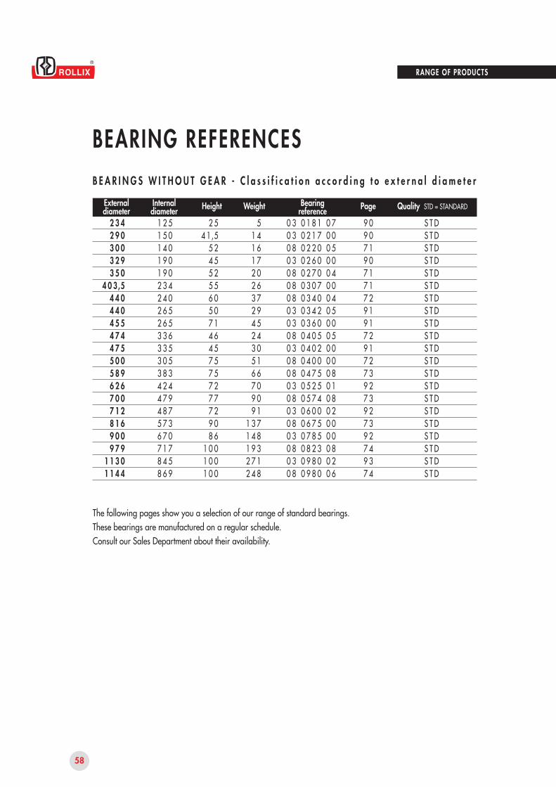
BEARING REFERENCESB E A R I N G S W I T H O U T G E A R - C l a s s i f i c a t i o n a c c o r d i n g t o e x t e r n a l d i a m e t e r
The following pages show you a selection of our range of standard bearings.These bearings are manufactured on a regular schedule.Consult our Sales Department about their availability.
STD = STANDARDExternaldiameter
Internaldiameter
BearingreferenceHeight Weight QualityPage
2 3 42 9 03 0 03 2 93 5 0
4 0 3,54 4 04 4 04 5 54 7 44 7 55 0 05 8 96 2 67 0 07 1 28 1 69 0 09 7 9
1 1 3 01 1 4 4
1 2 51 5 01 4 01 9 01 9 02 3 42 4 02 6 52 6 53 3 63 3 53 0 53 8 34 2 44 7 94 8 75 7 36 7 07 1 78 4 58 6 9
2 54 1,5
5 24 55 25 56 05 07 14 64 57 57 57 27 77 29 08 6
1 0 01 0 01 0 0
51 41 61 72 02 63 72 94 52 43 05 16 67 09 09 1
1 3 71 4 81 9 32 7 12 4 8
0 3 0 1 8 1 0 70 3 0 2 1 7 0 00 8 0 2 2 0 0 50 3 0 2 6 0 0 00 8 0 2 7 0 0 40 8 0 3 0 7 0 00 8 0 3 4 0 0 40 3 0 3 4 2 0 50 3 0 3 6 0 0 00 8 0 4 0 5 0 50 3 0 4 0 2 0 00 8 0 4 0 0 0 00 8 0 4 7 5 0 80 3 0 5 2 5 0 10 8 0 5 7 4 0 80 3 0 6 0 0 0 20 8 0 6 7 5 0 00 3 0 7 8 5 0 00 8 0 8 2 3 0 80 3 0 9 8 0 0 20 8 0 9 8 0 0 6
S T DS T DS T DS T DS T DS T DS T DS T DS T DS T DS T DS T DS T DS T DS T DS T DS T DS T DS T DS T DS T D
9 09 07 19 07 17 17 29 19 17 29 17 27 39 27 39 27 39 27 49 37 4
94
RANGE OF PRODUCTS
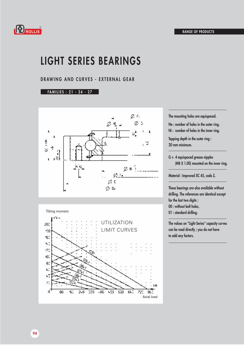
L IGHT SERIES BEARINGSD R AW I N G A N D C U R V E S - E X T E R N A L G E A R
FA M I L I E S : 2 1 - 2 4 - 2 7
The mounting holes are equispaced.
Ne : number of holes in the outer ring.Ni : number of holes in the inner ring.
Tapping depth in the outer ring :20 mm minimum.
G = 4 equispaced grease nipples(M8 X 1.00) mounted on the inner ring.
Material : Improved XC 45, code Z.
These bearings are also available without drilling. The references are identical except for the last two digits : 00 : without bolt holes,01 : standard drilling.Tilting moment
Axial load
UTILIZATIONLIMIT CURVES
The values on "Light Series" capacity curves can be read directly ; you do not have to add any factors.

4
95
21 29
2 1 0 4 1 1 0 1
2 1 0 5 4 1 0 1
2 1 0 6 4 1 0 1
2 1 0 7 4 1 0 1
2 1 0 8 4 1 0 1
2 1 0 9 4 1 0 1
2 1 1 0 9 1 0 1
3 3,8
4 1
4 1
4 1
5 5
5 5
5 5
3 2
4 4
5 2
6 0
6 8
7 6
8 6
5 0 5
6 4 0
7 4 2
8 4 0
9 5 0
1 0 4 6
1 1 9 8
3 0 4
4 3 4
5 3 4
6 3 4
7 3 4
8 3 4
9 8 4
3 6 8
4 9 8
5 9 8
6 9 8
7 9 8
8 9 8
1 0 4 8
4 5 5
5 8 5
6 8 5
7 8 5
8 8 5
9 8 5
1 1 3 5
1 0
1 4
1 6
1 8
1 8
2 0
2 2
3 3 2
4 6 2
5 6 2
6 6 2
7 6 2
8 6 2
1 0 1 2
1 2
1 4
1 6
1 6
1 8
2 0
2 0
5
6
6
6
8
8
8
9 9
1 0 5
1 2 2
1 3 8
1 1 7
1 2 9
1 4 8
4 9 5
6 3 0
7 3 2
8 2 8
9 3 6
1 0 3 2
1 1 8 4
RANGE OF PRODUCTS
L IGHT SERIES BEARINGSR E F E R E N C E S - E X T E R N A L G E A R
M E A S U R E M E N T S I N M I L L I M E T E R S
De Di Bi Fe Ne Fi Ni m z DWEIGHT
KgGEARSFASTENINGDIMENSIONSREFERENCES Teeth resistance
kN
The characteristics of these classes are tabulated on the table page 106.Please consult us, for the class suitable for your application.
Famil ies 21 : c lass I have al l the same geometr y24 : c lass I I I 27 : c lass V
FA M I L I E S : 2 1 - 2 4 - 2 7
to

96
RANGE OF PRODUCTS
L IGHT SERIES BEARINGSD R AW I N G A N D C U R V E S - I N T E R N A L G E A R
FA M I L I E S : 2 2 - 2 5 - 2 8
The mounting holes are equispaced.
Ne : number of holes in the outer ring.Ni : number of holes in the inner ring.
Tapping depth in the inner ring :20 mm minimum.
G = 4 equispaced grease nipples (M8 X 1.00) mounted on the outer ring.
Material : Improved XC 45, code Z.
These bearings are also available without drilling. The references are identical except for the last two digits : 00 : without bolt holes,01 : standard drilling.Tilting moment
Axial load
UTILIZATIONLIMIT CURVES
The values on "Light Series" capacity curves can be read directly ; you do not have to add any factors.

97
4
21 29
2 2 0 4 1 1 0 1
2 2 0 5 4 1 0 1
2 2 0 6 4 1 0 1
2 2 0 7 4 1 0 1
2 2 0 8 4 1 0 1
2 2 0 9 4 1 0 1
2 2 1 0 9 1 0 1
3 2,4
4 0,3
4 0,3
4 0,3
5 4,3
5 4,3
5 4,3
3 1
4 1
4 8
5 5
6 3
7 1
8 0
5 1 8
6 4 8
7 4 8
8 4 8
9 4 8
1 0 4 8
1 1 9 8
3 2 5
4 4 5
5 4 6
6 4 9
7 3 6
8 4 0
9 8 6
4 5 4
5 8 4
6 8 4
7 8 4
8 8 4
9 8 4
1 1 3 4
4 9 0
6 2 0
7 2 0
8 2 0
9 2 0
1 0 2 0
1 1 7 0
8
1 0
1 2
1 2
1 4
1 6
1 6
3 7 5
5 0 5
6 0 5
7 0 5
8 0 5
9 0 5
1 0 5 5
1 2
1 6
1 8
2 0
2 0
2 2
2 4
5
6
6
6
8
8
8
6 7
7 6
9 3
1 1 0
9 4
1 0 7
1 2 5
3 3 5
4 5 6
5 5 8
6 6 0
7 5 2
8 5 6
1 0 0 0
RANGE OF PRODUCTS
L IGHT SERIES BEARINGSR E F E R E N C E S - I N T E R N A L G E A R
The characteristics of these classes are tabulated on the table page 106.Please consult us, for the class suitable for your application.
Famil ies 22 : c lasseI have al l the same geometr y.25 : c lass I I I 28 : c lass V
FA M I L I E S : 2 2 - 2 5 - 2 8
M E A S U R E M E N T S I N M I L L I M E T E R S
De Di Be Fe Ne Fi Ni m z DWEIGHT
KgGEARSFASTENINGDIMENSIONSREFERENCES Teeth Resistance
kN
to

98
RANGE OF PRODUCTS
L IGHT SERIES BEARINGSD R AW I N G A N D C U R V E S - W I T H O U T G E A R
FA M I L I E S : 2 3 - 2 6 - 2 9
The mounting holes are equispaced.
Ne : number of holes in the outer ring.Ni : number of holes in the inner ring.
G = 4 equispaced grease nipples (M8 X 1.00) mounted on each ring.
Material : Improved XC 45, code Z.
These bearings are also available without drilling. The references are identical except for the last two digits : 00 : without bolt holes,01 : standard drilling.
Tilting moment
Axial load
UTILIZATIONLIMIT CURVES
The values on "Light Series" capacity curves can be read directly ; you do not have to add any factors.

99
4
21 29
2 3 0 4 1 1 0 1
2 3 0 5 4 1 0 1
2 3 0 6 4 1 0 1
2 3 0 7 4 1 0 1
2 3 0 8 4 1 0 1
2 3 0 9 4 1 0 1
2 3 1 0 9 1 0 1
2 3
3 4
4 0
4 6
5 2
5 8
6 7
5 1 8
6 4 8
7 4 8
8 4 8
9 4 8
1 0 4 8
1 1 9 8
3 0 4
4 3 4
5 3 4
6 3 4
7 3 4
8 3 4
9 8 4
4 5 4
5 8 4
6 8 4
7 8 4
8 8 4
9 8 4
1 1 3 4
3 6 8
4 9 8
5 9 8
6 9 8
7 9 8
8 9 8
1 0 4 8
4 9 0
6 2 0
7 2 0
8 2 0
9 2 0
1 0 2 0
1 1 7 0
8
1 0
1 2
1 2
1 4
1 6
1 6
3 3 2
4 6 2
5 6 2
6 6 2
7 6 2
8 6 2
1 0 1 2
1 2
1 4
1 6
1 6
1 8
2 0
2 0
RANGE OF PRODUCTS
L IGHT SERIES BEARINGSR E F E R E N C E S - W I T H O U T G E A R
FA M I L I E S : 2 3 - 2 6 - 2 9
The characteristics of these classes are tabulated on the table page 106.Please consult us, for the class suitable for your application.
Famil ies 23 : c lass I have all the same geometry.26 : c lass I I I 29 : c lass V
to
M E A S U R E M E N T S I N M I L L I M E T E R S
De Di Be Bi Fe Ne Fi NiWEIGHT
KgFASTENINGDIMENSIONSREFERENCES

100
RANGE OF PRODUCTS
LIGHT SERIES SOLID SECTIONS BEARINGSD R AW I N G A N D C U R V E S - E X T E R N A L G E A R
FA M I L I E S : 3 1 - 3 4 - 3 7
The mounting holes are equispaced.
Ne : number of holes in the outer ring.Ni : number of holes in the inner ring.
Tapping depth in the outer ring : 20 mm minimum.
G = 4 equispaced grease nipples (M8 X 1.00) mounted on the inner ring.
Material : Improved XC 45, code Z.
Pilot Ce : height 3 mm, quality H9.Pilot Ci : height 10 mm, quality H9.
These bearings are also available with through holes. The references are identical except for the last two digits : 01 : through holes inner ring,11 : through holes outer ring.
The values on "Light Series" capacity curves can be read directly ; you do not have to add any factors.
Tilting moment
Axial load
UTILIZATIONLIMIT CURVES

101
4
31 39
3 1 0 4 1 1 0 1
3 1 0 5 4 1 0 1
3 1 0 6 4 1 0 1
3 1 0 7 4 1 0 1
3 1 0 8 4 1 0 1
3 1 0 9 4 1 0 1
3 1 1 0 9 1 0 1
33,8
41
41
41
55
55
55
32
46
55
62
71
78
91
505
640
742
840
950
1046
1198
342
472
572
672
772
872
1022
412,2
542,5
642
743
842
943
1094
344
474
574
674
774
874
1024
455
585
685
785
885
985
1135
20
28
32
36
36
40
44
368
498
598
698
798
898
1048
24
32
36
40
40
44
48
5
6
6
6
8
8
8
99
105
122
138
117
129
148
495
630
732
828
936
1032
1184
RANGE OF PRODUCTS
LIGHT SERIES SOLID SECTIONS BEARINGSR E F E R E N C E S - E X T E R N A L G E A R
FA M I L I E S : 3 1 - 3 4 - 3 7
The characteristics of these classes are tabulated on the table page 106.Please consult us, for the class suitable for your application.
Famil ies 31 : c lass I have al l the same geometr y.34 : c lass I I I 37 : c lass V
M E A S U R E M E N T S I N M I L L I M E T E R S
De Di Ce Ci Fe Ne Fi Ni m z DWEIGHT
KgGEARSFASTENINGDIMENSIONSREFERENCES Teeth Resistance
kN
to

102
RANGE OF PRODUCTS
LIGHT SERIES SOLID SECTIONS BEARINGSD R AW I N G A N D C U R V E S - I N T E R N A L G E A R
FA M I L I E S : 3 2 - 3 5 - 3 8
The mounting holes are equispaced.
Ne : number of holes in the outer ring.Ni : number of holes in the inner ring.
Tapping depth in the inner ring : 20 mm minimum.
G = 4 equispaced grease nipples(M8 X 1.00) mounted on the outer ring.
Material : Improved XC 45, code Z.
Spigot Ce : height 10 mm, quality f9.Spigot Ci : height 3 mm, quality f9.
Tilting moment
Axial load
UTILIZATIONLIMIT CURVES
The values on "Light Series" capacity curves can be read directly ; you do not have to add any factors.

103
4
31 39
3 2 0 4 1 1 0 1
3 2 0 5 4 1 0 1
3 2 0 6 4 1 0 1
3 2 0 7 4 1 0 1
3 2 0 8 4 1 0 1
3 2 0 9 4 1 0 1
3 2 1 0 9 1 0 1
32,4
40,3
40,3
40,3
54,3
54,3
54,3
31
43
51
58
70
76
92
486
616
716
816
916
1016
1166
325
445
546
649
736
840
986
484
614
714
814
914
1014
1164
409,5
539,5
639
739,7
840
939
1089
460
590
690
790
890
990
1140
24
32
36
40
40
44
48
375
505
605
705
805
905
1055
24
32
36
40
40
44
48
5
6
6
6
8
8
8
67
76
93
110
94
107
125
335
456
558
660
752
856
1000
RANGE OF PRODUCTS
R E F E R E N C E S - I N T E R N A L G E A R
FA M I L I E S : 3 2 - 3 5 - 3 8
The characteristics of these classes are tabulated on the table page 106.Please consult us, for the class suitable for your application.
Famil ies 32 : c lass I have al l the same geometr y.35 : c lass I I I 38 : c lass V
M E A S U R E M E N T S I N M I L L I M E T E R S
De Di Ce Ci Fe Ne Fi Ni m z DWEIGHT
KgGEARSFASTENINGDIMENSIONSREFERENCES Teeth Resistance
kN
LIGHT SERIES SOLID SECTIONS BEARINGS
to

104
RANGE OF PRODUCTS
LIGHT SERIES SOLID SECTIONS BEARINGSD R AW I N G A N D C U R V E S - W I T H O U T G E A R
FA M I L I E S : 3 3 - 3 6 - 3 9
The mounting holes are equispaced.
Ne : number of holes in the outer ring.Ni : number of holes in the inner ring.
G = 4 equispaced grease nipples(M8 X 1.00) mounted on the outer ring.
Material : Improved XC 45, code Z.
Spigot Ce : height 10 mm, quality f9.Pilot Ci : height 10 mm, quality H9.
Tilting moment
Axial load
UTILIZATIONLIMIT CURVES
The values on "Light Series" capacity curves can be read directly ; you do not have to add any factors.
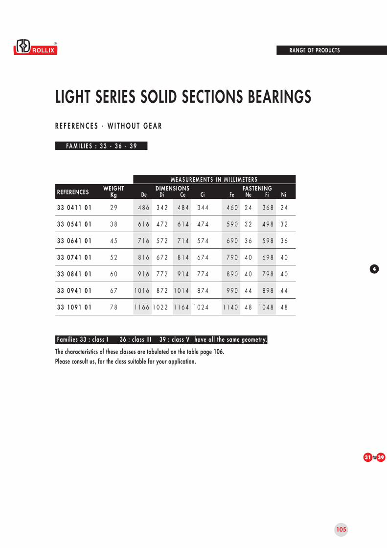
105
4
31 39
3 3 0 4 1 1 0 1
3 3 0 5 4 1 0 1
3 3 0 6 4 1 0 1
3 3 0 7 4 1 0 1
3 3 0 8 4 1 0 1
3 3 0 9 4 1 0 1
3 3 1 0 9 1 0 1
2 9
3 8
4 5
5 2
6 0
6 7
7 8
4 8 6
6 1 6
7 1 6
8 1 6
9 1 6
1 0 1 6
1 1 6 6
3 4 2
4 7 2
5 7 2
6 7 2
7 7 2
8 7 2
1 0 2 2
4 8 4
6 1 4
7 1 4
8 1 4
9 1 4
1 0 1 4
1 1 6 4
3 4 4
4 7 4
5 7 4
6 7 4
7 7 4
8 7 4
1 0 2 4
4 6 0
5 9 0
6 9 0
7 9 0
8 9 0
9 9 0
1 1 4 0
2 4
3 2
3 6
4 0
4 0
4 4
4 8
3 6 8
4 9 8
5 9 8
6 9 8
7 9 8
8 9 8
1 0 4 8
2 4
3 2
3 6
4 0
4 0
4 4
4 8
RANGE OF PRODUCTS
LIGHT SERIES SOLID SECTIONS BEARINGS
FA M I L I E S : 3 3 - 3 6 - 3 9
The characteristics of these classes are tabulated on the table page 106.Please consult us, for the class suitable for your application.
Famil ies 33 : c lass I have al l the same geometr y.36 : c lass I I I 39 : c lass V
M E A S U R E M E N T S I N M I L L I M E T E R S
De Di Ce Ci Fe Ne Fi NiWEIGHT
KgFASTENINGDIMENSIONSREFERENCES
R E F E R E N C E S - W I T H O U T G E A R
to

4 1 1
5 4 1
6 4 1
7 4 1
8 4 1
9 4 1
1 0 9 1
2 0 0
2 0 0
2 5 0
3 0 0
3 0 0
4 0 0
4 0 0
0 , 4 0
0 , 4 0
0 , 4 5
0 , 4 5
0 , 5 0
0 , 5 5
0 , 6 0
0 , 2 0
0 , 2 0
0 , 2 3
0 , 2 3
0 , 2 5
0 , 2 7
0 , 3 0
0 , 0 8
0 , 0 8
0 , 0 8
0 , 0 9
0 , 0 9
0 , 1 0
0 , 1 0
0 , 3 0
0 , 3 0
0 , 3 5
0 , 3 5
0 , 4 0
0 , 4 5
0 , 5 0
0 , 1 5
0 , 1 5
0 , 1 8
0 , 1 8
0 , 2 0
0 , 2 2
0 , 2 5
0 , 0 5
0 , 0 5
0 , 0 5
0 , 0 6
0 , 0 6
0 , 0 7
0 , 0 7
106
RANGE OF PRODUCTS
LIGHT SERIES AND SOLID SECTIONSTA B L E O F D E F L E C T I O N U N D E R M A S T E R L O A D
MASTERLOAD
(N) Class I Class III Class VClass I Class III Class V
MAXIMUM DEFLECTION(average 3 points)
MAXIMUM MEASUREMENTIN 1 POINT
RACEWAY MEAN DIAM.
(mm)
M E A S U R E M E N T S I N M I L L I M E T E R S

5
107
•
•
•
APPENDIX
COMMISSIONING DOCUMENTS
TECHNICAL DATA SHEET FOR THE SELECTION OF A SLEWING RING
WARRANTY - AFTER-SALES SERVICE

108
APPENDIX
COMMISSIONING DOCUMENTS
You have taken receipt of a "ROLLIX" slewing ring and we congratulate you for your choice.
The "slewing ring" product is a hightechnology product selected for precise parameters. It was designed and manufactured to the ISO 9000 standard and supplied based on the informations given in the questionnaire IT ETR 911.It will give you trouble free service if the operating conditions are in line with "ROLLIX" recommendations.
You are a designer, an installer or aretailer, it is your responsibility to check that your or your user's need have been correctly identified in our questionnaireIT ETR 911, that the installation requi-rements and our product maintenance conditions have to be fully respected.
We suggest you study the conditions inthis catalogue and our manual and instruction booklet IT ETR 941 so that you are certain of your responsibilities. These documents should be supplied to the user if the situation requires it.
In order to help you, we enclose a check-list which although not comprehensive, covers the minimum essential checks which have to be carried out in all cases.
In addition we suggest you make yourself aware of our guarantee conditions and their limitations.
CHOICE OF THE SLEWING RINGTo choose a suitable slewing ring, did you take into consideration :
• the nominal loads
• the overloads due to :
• wind
• snow
• operating conditions
• the loads due to dynamic effects
• peak loads
• test overloadsThis for :
• the raceway
• the gear
• the bolting
• the maximum utilization speed
On receipt,be sure that the slewing ring you receive is the one you have ordered (identification plate).
Storage conditions,
• during the storage time, has the product been protected against external contamination ?
• If storage has exceeded 18 months, has the slewing ring been regreased before installation ?
IT DTR 19.005

5
109
APPENDIX
Before installation,be sure that the product has not been subjected to shock loads resulting in an alteration of its characteristics (irreversible deformation),
• seals are in place
• seals are not damaged(cut)
• your handling equipment are suitable for the product :
• quality
• size
• weight
During installation,check :
• the flatness of the supporting base
• the dimensions of the structures
• the position of the filler plug
• the position of the hardening junctionin relation to the axis of maximum moments.
During fastening,check :
• the grade of screws and bolts
• the number of bolts used
• the specified tightening torque
• that the tightening torque is achieved using properly lubricated threads
• that split, fan-shaped or elastic washers are not used
• that hardened flat washers are used if required
Installation of the pinion gear(if necessary),check :
• the pinion corresponds to the gear of the slewing ring
• there is no risk of interference
• the minimum backlash is maintened
• the measurement is determined at the point of :
• maximum offset of the external gear
• maximum offset of the internal gear
• the slewing ring / pinion centre distance cannot vary
• the contact area of the pinion on the slewing ring gear face is uniform
Before installation,be sure :
• the maximum slewing ring speed will not exceed the calculated value
• no objects will foul the slewing ring rotation
• no objects will damage the seals
• the slewing ring and its pinion do not cause any danger
• to material
• to people
• that protection complies with the recommendations of 89/392 EEC
COMMISSIONING DOCUMENTS
IT DTR 19.005

110
APPENDIX
COMMISSIONING DOCUMENTS
• Check
• the deflection under the maximum design load and record the results
• the rotation is without abnormal noise or tight spots
After the installation,
• be sure,
• no deformation can affect the functionning of the assembly
• no deformation can decrease the life of the product
In operation,
• be sure that the user :
• knows the lubrication specifications and in particular :
• type of grease
• frequency of lubrication
• the method of regreasingand this for :
• the rolling elements
• the gear
• will observe the condition of seals
• knows the frequency
• of checking bolt tightening
• of bolt replacement
• knows the maximum permissible clearance in the product beforedismounting
• or the designed maximum clearance allowable
IT DTR 19.005
• For your information :
A manuel and instruction bookletIT ETR 941 is available upon request at our Commercial Department. We advise you to include our maintenance specifications in those of the machine or failing that, to transmit them to the user.

S.R. Pinion Loads S.R. Pinion
Tangentiel load (kN)
Torque (kNm)
3, Rue Louis Renault B.P. 329
F - 44803 ST HERBLAIN Cedex
Tel. 33 (0)2 40 67 89 89
Fax 33 (0)2 40 67 89 03
E-mail : [email protected]
D E S I G N D ATA S H E E T
1.1
1.2
1.3
2.1
2.2
2.3
3.1
3.2
3.3
3.4
3.5
3.6
3.7
3.8
3.9
3.10
4.1
4.2
4.3
4.4
5.1
5.2
5.3
6.1
6.2
6.3
7.1
8.1
COMPANY :
Address :
Person in charge of the project :
DESCRIPTION OF THE APPLICATION + sketch (to be attached with loads applied)
Machine / project reference :
Slewing ring position : Horiz. Vert. Other Utilisation mode : Continu. Intermittent Other
LOADS ON THE BEARING (including structural loads) : Applied Suspended
Utilisation
Axial
Radial
Moment
Rotating ring : Ext Int Speed (RPM)
Load factors applied : Excluded Included Values :
Required life :
GEAR
Geometry
Required Module
Number of teeth required
Addendum modif.factor
CRITICAL ITEMS
Classification Commission FEM LLOYDS API BV DNV Other
Specification relative to the application :
SPECIFIC REQUIREMENTS OF THE APPLICATION
Environment :
Vibrations, shocks loads :
Acceleration :
QUANTITY Yearly requirements :
REQUIRED DELIVERY TIME :
Tel. :
Fax :
Fonction :
New project : Yes No
% Time
kN
kN
kNm
Nominal Maximum Test Nominal Maximum Test
External Internal Without gear
Dimensions Others :
Operating temperature :
Storing temperature :
Deceleration : Inert. mom./Rotation axis : Varied :
Qty per delivery :
For ROLLIX
N° Affaire :
Date :
AC VI RC
Visa :
For the USER
Name :
Date :
Signature :
Document available at the Commercial DepartmentIT ETR 911
Static Dynamic

112
APPENDIX
WARRANTY - AFTER-SALES SERVICE
OBJECT OF THE WARRANTY
The ROLLIX DEFONTAINE "SLEWINGRING" product is warranted for good working within the scope of normal usage under the following criteria :
• for standard products, usage is asper the conditions of application, the technical specifications as indicated in the catalogue reference IT ETR 921 and the instruction manual IT ETR 941 applicable to the product.
• for all products, usage is as per theindications provided by the customer in answer to the questionnaire referenceIT ETR 911.
WARRANTY PERIODThe warranty for slewing ring gears is for TWO YEARS after delivery, and FIVE YEARS after delivery with regard to defects in: • Material origin,• Manufacture• Factory assembly.
For geometric defects, the warranty period however remains fixed at TWO YEARS after delivery.
In all cases, the warranty period is limited to the estimated service life of the product as shown in our calculation sheets or other ROLLIX documents. This theoretical value comes from a statistical calculation and canin no way be considered as a commitment as to the result.
CONDITIONS OF APPLICATION - EXCLUSIONS
The warranty of the "SLEWING RING"product with respect to the application will not apply in the various following cases :
The questionnaire reference IT ETR 911has not been completed and returned to ROLLIX.The "SLEWING RING" product is a high technology product destined to satisfy PRECISE NEEDS.
The supply of a suitable producttherefore depends on ROLLIX knowing the exact conditions of application and expected utilization by the customer.
A specific questionnaire referenceIT ETR 911, constituting specifications are systematically made available to the customer before order placement.
The supply of a product suitable to customer's needs is based on his precise and complete answers to the questionnaire IT ETR 911. Application conditions which fall outside the stipulations thereon may constitute a case of exclusion of the ROLLIX warranty.
Non-compliance with ROLLIX recommendationsHandling, utilization, mounting and maintenance which do not comply with our recommendations listed on the maintenance manual of the product sold, notably :
Handling• Handling equipment not suitable to the quality and weight of the parts.
Utilization• Utilization not complying with the technical specifications and with the conditions of application of the product.
Mounting• Incorrect dimensioning of the support structures under minimum stated limits and flatness out of tolerances.• Incorrect positioning of the filler plug with respect to the axis of moments.
1
2

5
113
APPENDIX
Fastening• Screws and nuts not complying to our recommendations as well as to the required pretensioning.• Utilization of split, fan-shaped, elastic or non-hardened washers whatever the brand or the model.
GreasingNon-compliance with recommended types of grease as well as regreasing frequency.
Storage• Non renewal of the external protective substance after six month storage.• No regreasing of the slewing ring in rotation after eighteen month storage.
Modification, dismantling or repair of the product carried out without ROLLIX previous agreement.
Damage resulting from normal wear of the materialThe increase of clearance under load within the scope of the utilization limits constitutes normal wear.The warranty is not applicable to the wearing parts such as seals.More generally, the warranty will not be applied in case of malfunctions resulting directly or indirectly from a fault or an act of negligence of the customer.
IMPLEMENTATION OF THE WARRANTY
The warranty for the satisfactoryfunctioning of the "SLEWING RING" product will be granted after :• notification of malfunction by the customer in the allotted time(see page 112 : WARRANTY PERIOD)• observation of the malfunction by ROLLIX• examination of the respective product's technical specifications, ROLLIX previous recommendations and other conditions applicable to the warranty.
No return will be accepted withoutROLLIX prior agreement, that is to say after receipt of the duly filled in appendix 1 of the procedure PG.CRX.19.00.
WARRANTY
In the case of notified malfunctionobserved, and after carrying out the usual examinations, ROLLIX will proceed to :
• repair of the SLEWING RING withpossible replacement of the parts considered damaged,• or arrange for the free replacement of the SLEWING RING,• or arrange for the reimbursement of the sale value of the SLEWING RING.
In all cases, ROLLIX reserves the right to select the most suitable solution for the problem observed.
The ROLLIX warranty is strictly limitedto repair, replacement or reimburse-ment of the part considered damaged, and therefore will not be extended to any other consequential damage likely to be linked to the malfunction : machine stoppages, damage of goods other than those of the contract, loss of income...
In the case of malfunction of a"SLEWING RING" product which is linked to an act of negligence or a fault of the customer, and notably to the non compliance of the ROLLIX recom-mendations, the survey costs of the damaged part, including transport and all travelling expenses for technicians to the commission site will be charged to the customer's account.
CAUTION
All data and informations contained in the present catalogue have been carefully evaluated and checked. We cannot, however, be liable for any errors or omissions. We reserve the right to make all technical changes and amendments in tests, formulae and drawings without prior notice.
All earlier editions are invalid witheffect from the publication of this catalogue.
WARRANTY - AFTER-SALES SERVICE
3
4

Crossed Rollers External Gear CODE 06


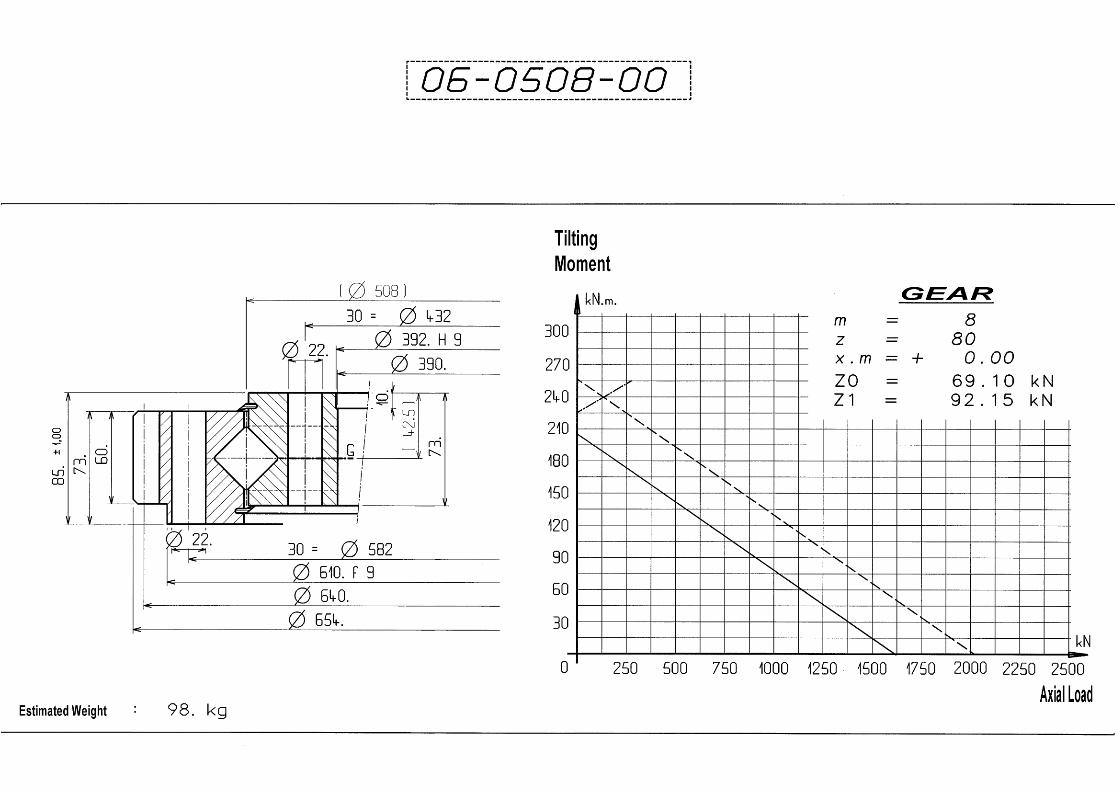
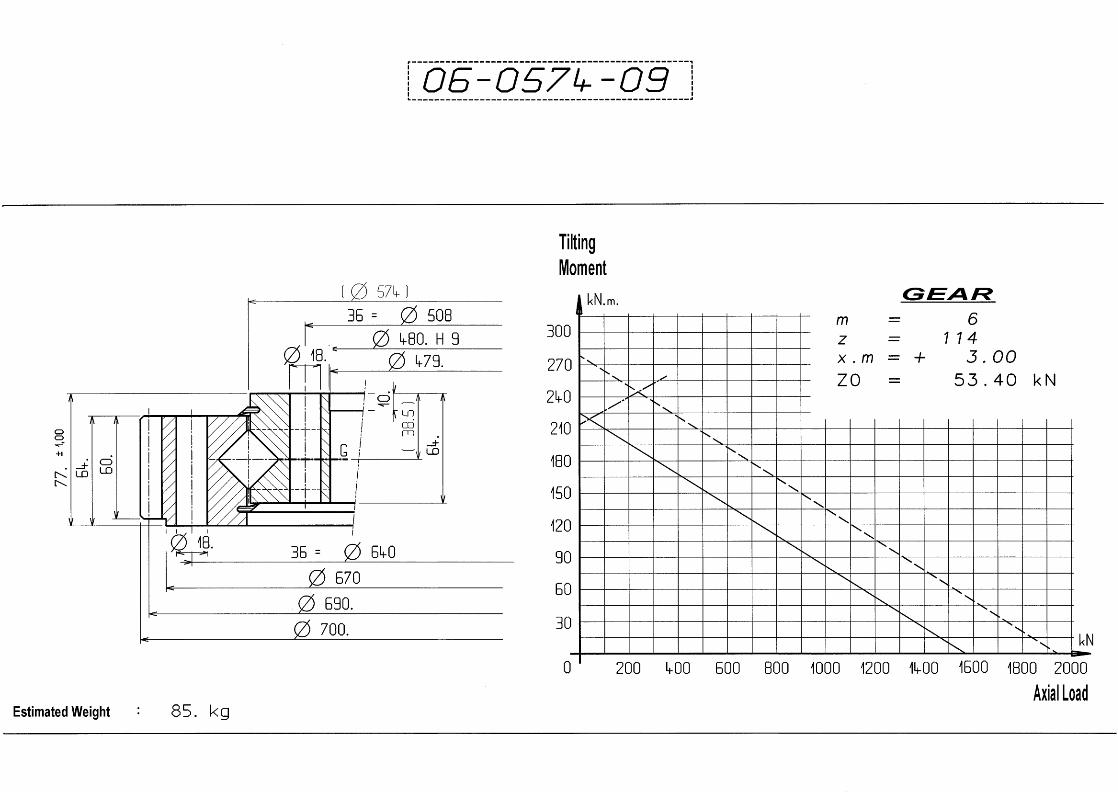


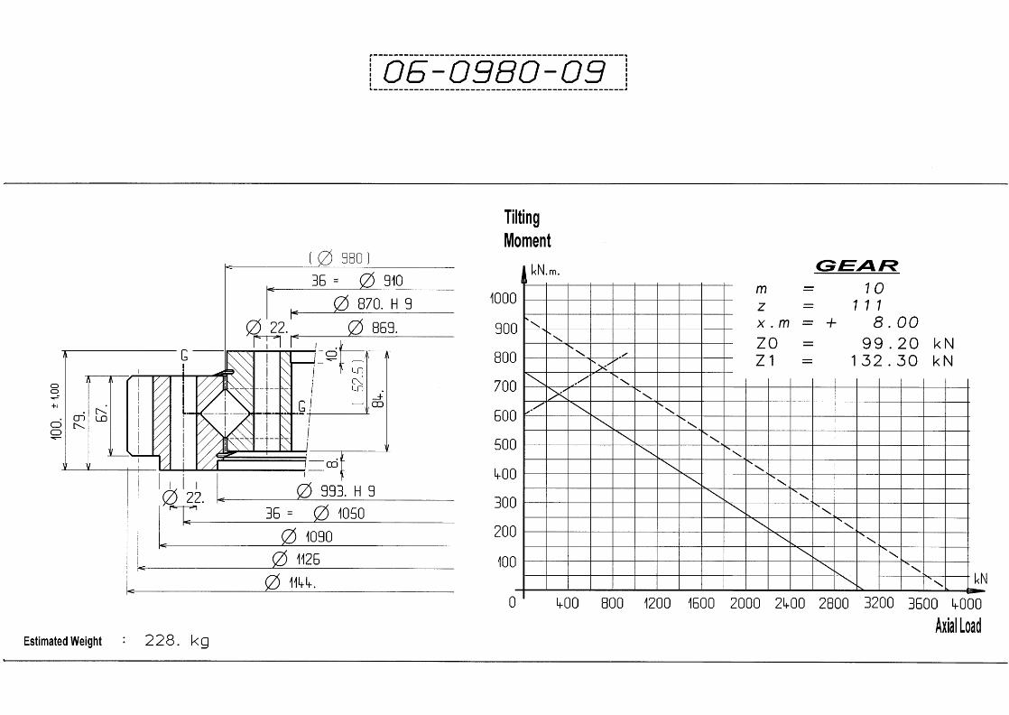


Crossed Rollers Internal Gear CODE 07


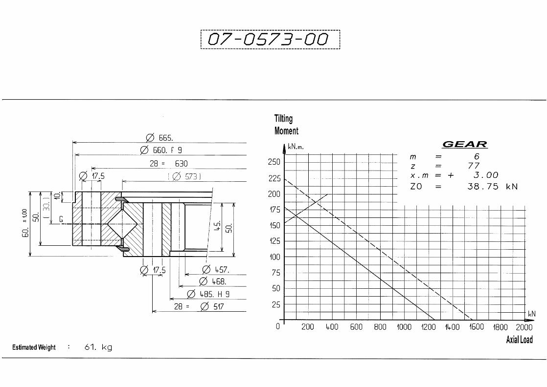


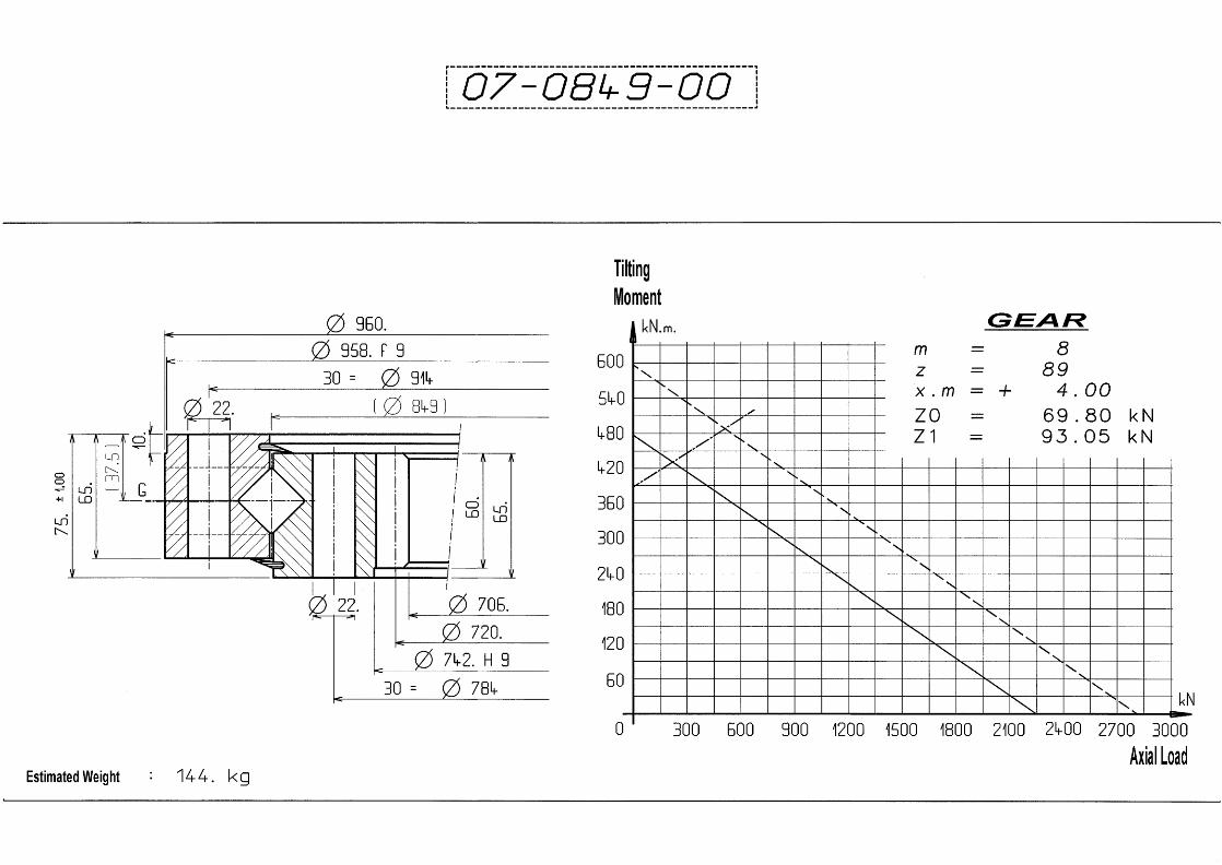

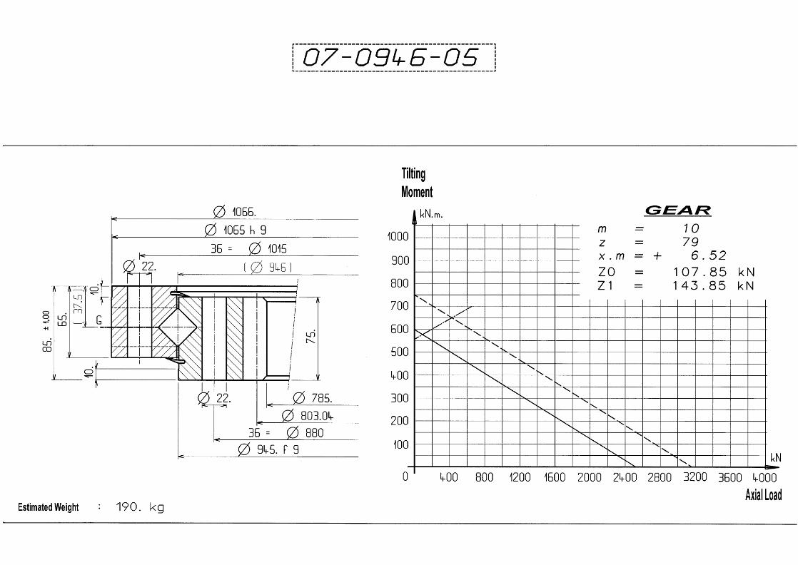


Crossed Rollers Without Gear CODE 08


Balls External Gear CODE 01
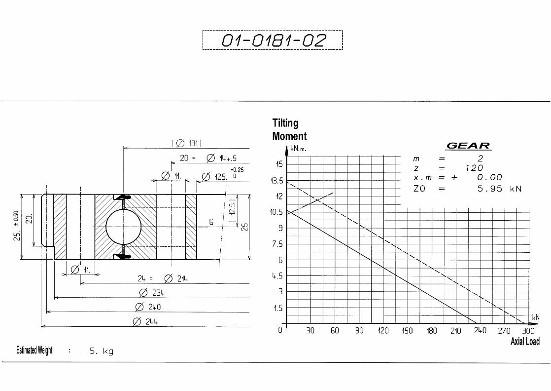

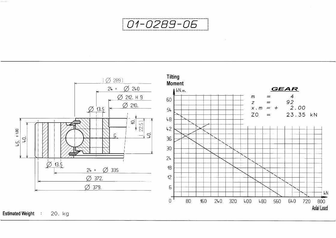


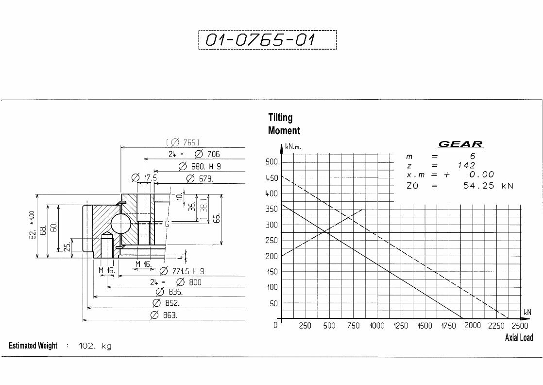


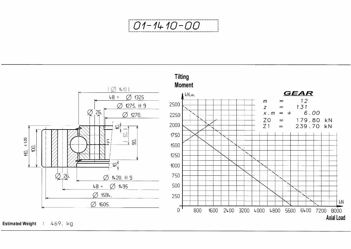


Balls Internal Gear CODE 02


Balls Without Gear CODE 03


