rolling contact fatigue life of rail for different slip ... · observe the consequences of severity...
TRANSCRIPT
2243
Abstract A three-dimensional elastic-plastic finite element analysis (FEA) is car-ried out to estimate the rolling contact fatigue (RCF) crack initiation life for varied slip range on the rail arising from operational variations. The wheel load produces Hertzian contact pressure. Variation in en-gine traction induces slip variations that evolves thermal load in terms of heat flux. The aperiodic rolling of wheel on rail develops non-pro-portional multiaxial fatigue loading. Present study combines these ef-fects by translating the wheel load on rail for multiple (twelve) pass in presence of thermal load, contact pressure and traction through a pro-posed simulation. The temperature dependent Chaboche material model with nonlinear kinematic hardening law is implemented to esti-mate the stresses and plastic strains governing the multiaxial fatigue condition at the interface. The location of maximum von Mises stress, found at a material point on or a layer below the rail-head, contem-plates the fatigue crack initiation site. A coded search algorithm helps to identify the critical plane of crack initiation corresponding to the maximum fatigue parameter (FP). In contrast to available predictions of RCF life considering contact pressure and/or traction or frictional heat in isolation, present study combines all these loads together and provides a more realistic result by numerical simulation.
Keywords Wheel-rail contact; slippage; non-proportional loading; ratchetting; critical plane; rolling contact fatigue.
Rolling Contact Fatigue Life of Rail for Different Slip Conditions
1 INTRODUCTION
Rails in general experience cyclic rolling contact load produced by the pattern of repeated passage of wheel on the rail. The rolling of wheel load causes variation in the directions of the principal stress and strain tensors with time at a given material point of the rail. The aperiodic cyclic loading causes a non-proportional multiaxial stress-strain response of the material. In effect, with the passage of time, this initiate rolling contact fatigue (RCF) cracks that may originate from a surface point or
Jay Prakash Srivastava a,*
Prabir Kumar Sarkar a V R Kiran Meesala b Vinayak Ranjan c
a Department of Mechanical Engineering, Indian Institute of Technology (ISM), Dhanbad, Jharkhand-826004, INDIA b Senior Design Engineer, The Tata Power Company Limited Strategic Engineering Division, Bangalore - 560100, INDIA c Department of Mechanical Engineering, Bennett University, Greater Noida, Ut-tar Pradesh-201310, INDIA
* Corresponding Author:[email protected]
http://dx.doi.org/10.1590/1679-78254161
Received 25.06.2017 Accepted 25.08.2017 Available online 26.08.2017
2244 J.P. Srivastava et al. / Rolling Contact Fatigue Life of Rail for Different Slip Conditions
Latin American Journal of Solids and Structures 14 (2017) 2243-2264
sub-surface level. These cracks can grow and join to detach material in the form of shelling and spalling defects. In extreme cases, crack extension from these defects leads to catastrophic rail fracture. Such criticality of RCF damage/crack initiation has made it an area of intense research interest worldwide. The necessity is to meet the demand of carrying higher axle load, increased traffic density and higher speed.
Two main physical processes that govern the development of RCF defects are crack initiation and crack propagation in the rails. Among these, the prediction of crack initiation is of prime im-portance for railway maintenance engineers to schedule the appropriate rail grinding intervals. RCF defects arise from repeated overstressing of rail material, at surface and subsurface level, by the millions of wheel load cycles. The random changes in the state of stress and strain at a material point in rail promote fatigue behaviour. Therefore, an estimation of the stress and strain state due to cyclic rolling contact becomes essential for the assessment of structural integrity of the rail.
The rail transport operation system repeatedly modifies the rolling-sliding contact environment, over the contact region, by the formation of partial slip to full slip and vice-versa. The level of slip varies with traction force, hunting oscillations, steering, braking conditions and curve tracking. Carter (1926) provided the procedure for tracing the stick-slip distribution at the dynamic contact interface using the concept of Reynolds (Paul, 1975). He demonstrated the stick zone confined to the leading edge of the contact area and formation of the slippage at the trailing end. The stick-slip region together activates microslipage that raises the temperature due to frictional heat. This localized tem-perature rise modifies the stress state at the tiny contact patch. At higher temperature yield strength of the rail material decreases. This favours plastic deformation of the rail surface with each wheel pass. The effect of frictional heat together with the Hertzian contact pressure and traction is consid-ered in this investigation for evaluation of stress-strain histories.
Much of research on fatigue life estimation from RCF crack can be found in the published litera-ture (Ekberg and Sotkovszki, 2001; Haidari and Tehranib, 2015; Makino et al., 2012; Reis and Freitas, 2014; Sciammarella et al., 2016; Sraml et al., 2003). Ringsberg and his coworkers (Ringsberg and Josefson, 2001; J. Ringsberg, 2003; J. W. Ringsberg, 2001; Ringsberg et al., 2000) provided fatigue life estimation considering patterns of load distribution, from Hertzian and non-Hertzian contact incorporating traction distribution without any thermal load. Ringsberg and Josefson (2001) observed the Hertzian contact load distribution results are in close agreement with their Swedish railway test site findings. A similar opinion is given by Carroll (2005), with the argument that after few load cycle, subsequent plastic deformation per cycle is very small that allow to assume elastic contact condition. Tyfour and Beynon (1994) observed accumulation of unidirectional plastic strain at and below the contact surface to be the main reason for surface and subsurface cracking once the unidirectional plastic strain exceeds the critical strain of ductility. Performing real-time field test with active data acquisition is quite complex, difficult and cost prohibitive. A numerical approach like finite element method is widely used by researchers to simulate the rail-wheel contact problem. Xu and Jiang (2002) used a two-dimensional finite element model incorporating cyclic plasticity theory to estimate the elastic-plastic stresses for the partial slip condition without involving the thermal load. Widiyarta et al. (2008) discussed ratcheting phenomenon to affect the rail wear and rolling contact fatigue by the influence of frictional heat alone. These authors, in their formulation, considered neither of the wheel load nor the traction load. Pun et al. (2015) simulated the wheel–rail contact problem by combining
J.P. Srivastava et al. / Rolling Contact Fatigue Life of Rail for Different Slip Conditions 2245
Latin American Journal of Solids and Structures 14 (2017) 2243-2264
non-Hertzian contact pressure with traction load. They studied ratcheting performance of rail steels without considering thermal load. Their material model assumes isotropic hardening behaviour. In contrary, Ahlström (2016) formed his metallurgical view point based opinion during residual stress study that suggests kinematic hardening behaviour is required in the material model for its accurate prediction.
Most of the work of earlier researchers considered either structural load imparted by axle load, or thermal load generated by friction, treating them separately. However, RCF related failure cannot be estimated from normal contact pressure alone. It's interdependence on traction forces and frictional heat is to be viewed simultaneously. In the present study, the problem is viewed as: Non-conformality of rail-wheel contact produce creepage which is further aggravated by hunting oscillation of wheels. Creepage introduces temperature rise. Together they affect the contact stress to promote plastic deformation. By continuous plastic strain accumulation in the material of contact centre vicinity, surrounded by elastic material, observed in layers, exhausts its ductility. This, due to repeated loading at the contact, initiates crack formation to release the plastic strain energy beneath the head material layers. After crack formation, its propagation activates RCF defect to lead to catastrophe. Dynamic wheel load and braking induced heat flux are not considered in the present study. This investigation combines the Hertzian contact pressure, longitudinal tangential traction based on Carter’s theory and heat flux distribution due to friction existing on the contact patch to simulate the wheel-rail contact problem. Corresponding effective wheel load is translated on the rail surface for twelve-wheel passes, at the wheel speed of 90 kmph, to estimate the stress-strain field governed fatigue response. The material model plays a critical role in the evaluation of their variations. For this, temperature de-pendent material parameters (Caprioli and Ekberg, 2014) are applied. A cyclic plasticity material model of Chaboche, featuring nonlinear kinematic hardening as in ANSYS 14.0, evaluates the de-manded stress-strain fields. Further processing of the result requires identification of critical plane containing the maximum FP. Jiang and Sehitoglu model can then be applied to calculate fatigue crack initiation life of the rail section considered.
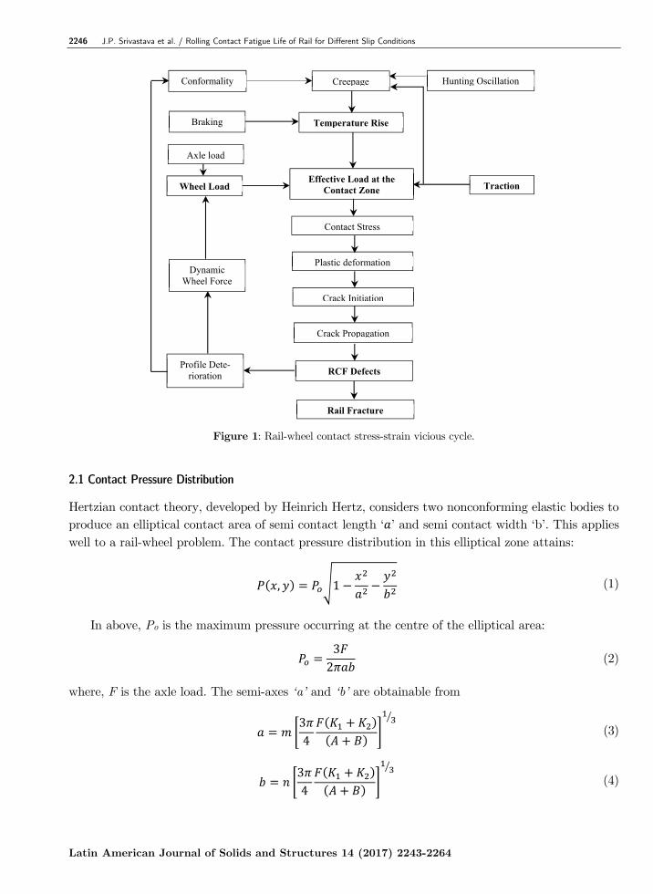
The analysis reveals rail material deterioration mechanisms arising from friction based thermo-mechanical load at the dynamic contact interface. Consequent results should provide useful infor-mation required for material development and to establish better maintenance strategies for safer and comfortable operation of the transport system. For clarity of the problem domain, the key aspects are summarized in the form of stress-strain vicious cycle, shown in Figure 1. 2 METHODOLOGY
The analytical model provides load distribution information implemented in finite element model to observe the consequences of severity in rail-wheel contact for micro-slip variations. For contact di-mension and pressure distribution, Hertzian theory is considered. Carter (1926) and Haines and Oller-ton (1963) models are employed for the evaluation of tangential traction for different partial slip conditions. Creepage and slip velocity are calculated for determination of frictional heat flux distri-bution. These load boundary conditions are input to the finite element model to obtain the time history of stress-strain field. These simulation results are used in Jiang and Sehitoglu (1999) model to identify the critical plane and estimate the fatigue crack initiation life.
2246 J.P. Srivastava et al. / Rolling Contact Fatigue Life of Rail for Different Slip Conditions
Latin American Journal of Solids and Structures 14 (2017) 2243-2264
Figure 1: Rail-wheel contact stress-strain vicious cycle.
2.1 Contact Pressure Distribution
Hertzian contact theory, developed by Heinrich Hertz, considers two nonconforming elastic bodies to produce an elliptical contact area of semi contact length ‘ ’ and semi contact width ‘b’. This applies well to a rail-wheel problem. The contact pressure distribution in this elliptical zone attains:
, 1 (1)
In above, Po is the maximum pressure occurring at the centre of the elliptical area:
32
(2)
where, F is the axle load. The semi-axes ‘a’ and ‘b’ are obtainable from
34
(3)
34
(4)
Axle load
Contact Stress
Plastic deformation
Crack Initiation
Crack Propagation
RCF Defects
Rail Fracture
Traction Effective Load at the
Contact ZoneWheel Load
Dynamic Wheel Force
Profile Dete-rioration
CreepageConformality Hunting Oscillation
Temperature RiseBraking
J.P. Srivastava et al. / Rolling Contact Fatigue Life of Rail for Different Slip Conditions 2247
Latin American Journal of Solids and Structures 14 (2017) 2243-2264
where, K1 and K2 are constants given by and , E1, E2 are Young’s moduli and
1, 2 are Poisson’s ratio of respective bodies. The ‘m’ and ‘n’ are Hertzian coefficients obtained by regression analysis. ‘A’ and ‘B’ are the geometrical constants depending on the principal relative radii of wheel and rail profile curvatures. The detail can be found in (Srivastava et al., 2013, 2014). The parameters used for the calculations are given in Table 1.
Parameters Symbol Value Unit Wagon wheel diameter D 0.915 m Wagon tonnage per axle M 17 tons
Semi axes rail-wheel contact ellipse a†, b† 7.32, 3.61 mm Normal maximum pressure † 1510 MPa
Coefficient of friction μ 0.38 - Ambient Temperature To 30 °C Heat partition factor 0.5 -
Environment - Dry - Train forward speed V 90 kmph Axle bogie distance L 1830 mm
† Magnitudes with superscript ‘†’ are evaluated from appropriate relations.
Table 1: Parameters used for present simulation.
2.2 Tangential Traction Distribution
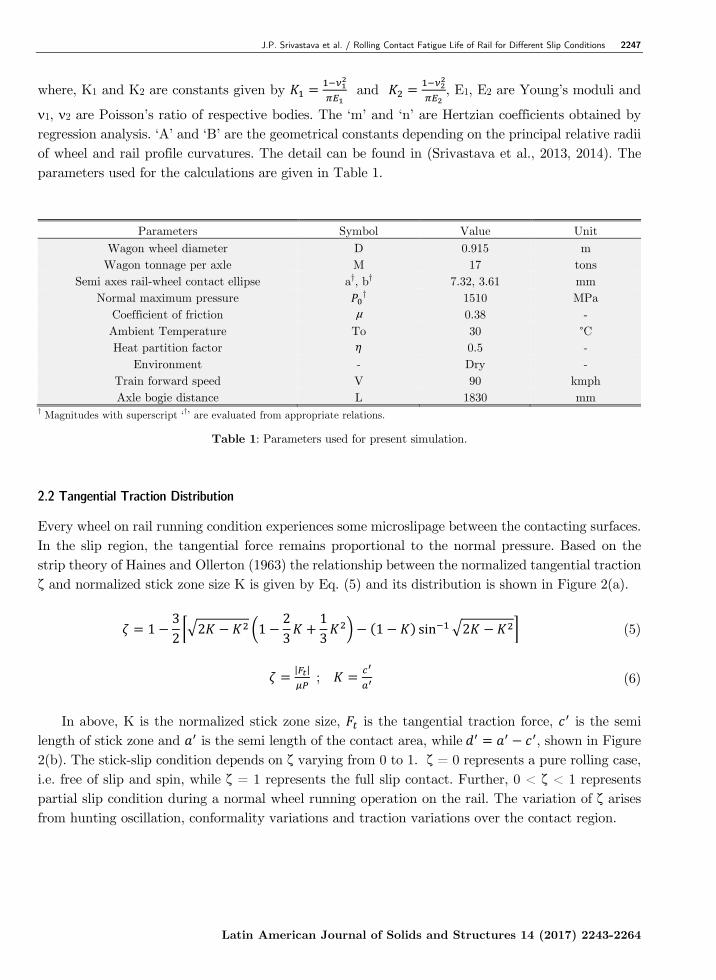
Every wheel on rail running condition experiences some microslipage between the contacting surfaces. In the slip region, the tangential force remains proportional to the normal pressure. Based on the strip theory of Haines and Ollerton (1963) the relationship between the normalized tangential traction ζ and normalized stick zone size K is given by Eq. (5) and its distribution is shown in Figure 2(a).
132
2 123
13
1 sin 2 (5)
| |
; (6)
In above, K is the normalized stick zone size, is the tangential traction force, is the semi
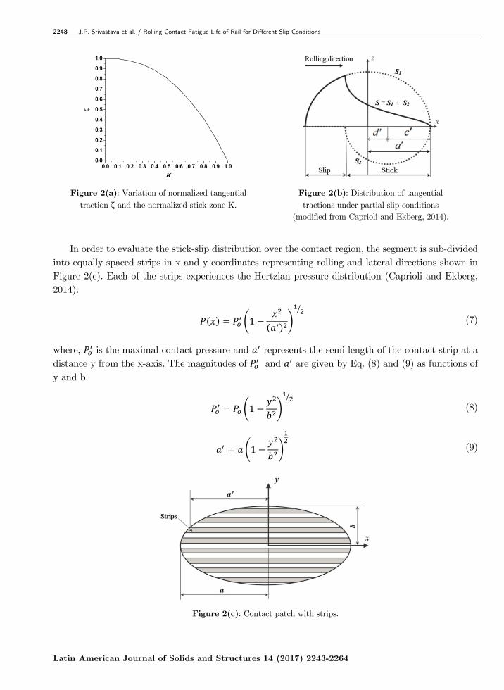
length of stick zone and is the semi length of the contact area, while , shown in Figure 2(b). The stick-slip condition depends on ζ varying from 0 to 1. ζ = 0 represents a pure rolling case, i.e. free of slip and spin, while ζ = 1 represents the full slip contact. Further, 0 < ζ < 1 represents partial slip condition during a normal wheel running operation on the rail. The variation of ζ arises from hunting oscillation, conformality variations and traction variations over the contact region.
2248 J.P. Srivastava et al. / Rolling Contact Fatigue Life of Rail for Different Slip Conditions
Latin American Journal of Solids and Structures 14 (2017) 2243-2264
0.0 0.1 0.2 0.3 0.4 0.5 0.6 0.7 0.8 0.9 1.00.0
0.1
0.2
0.3
0.4
0.5
0.6
0.7
0.8
0.9
1.0
K
Figure 2(a): Variation of normalized tangential traction ζ and the normalized stick zone K.
Figure 2(b): Distribution of tangential tractions under partial slip conditions
(modified from Caprioli and Ekberg, 2014).
In order to evaluate the stick-slip distribution over the contact region, the segment is sub-divided
into equally spaced strips in x and y coordinates representing rolling and lateral directions shown in Figure 2(c). Each of the strips experiences the Hertzian pressure distribution (Caprioli and Ekberg, 2014):
1 (7)
where, is the maximal contact pressure and represents the semi-length of the contact strip at a distance y from the x-axis. The magnitudes of and are given by Eq. (8) and (9) as functions of y and b.
1 (8)
1 (9)
Figure 2(c): Contact patch with strips.
J.P. Srivastava et al. / Rolling Contact Fatigue Life of Rail for Different Slip Conditions 2249
Latin American Journal of Solids and Structures 14 (2017) 2243-2264
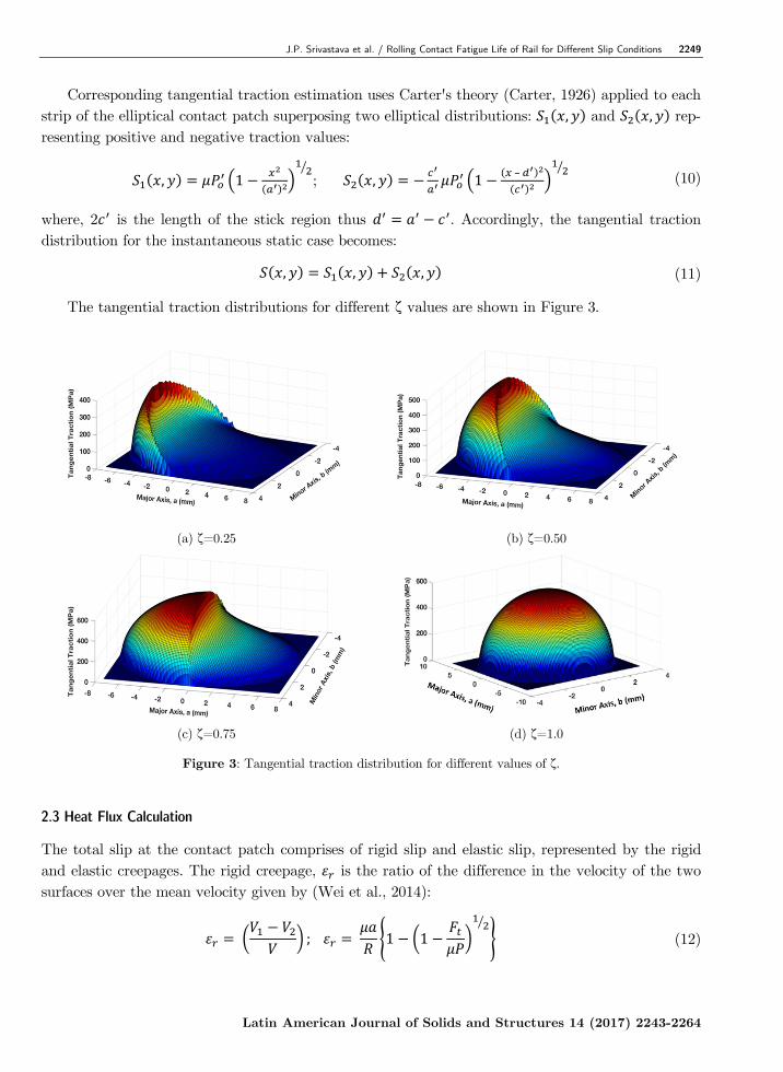
Corresponding tangential traction estimation uses Carter's theory (Carter, 1926) applied to each strip of the elliptical contact patch superposing two elliptical distributions: , and , rep-resenting positive and negative traction values:
, 1 ; , 1– (10)
where, 2 is the length of the stick region thus . Accordingly, the tangential traction distribution for the instantaneous static case becomes:
, , , (11)
The tangential traction distributions for different ζ values are shown in Figure 3.
(a) ζ=0.25 (b) ζ=0.50
(c) ζ=0.75 (d) ζ=1.0
Figure 3: Tangential traction distribution for different values of ζ.
2.3 Heat Flux Calculation
The total slip at the contact patch comprises of rigid slip and elastic slip, represented by the rigid and elastic creepages. The rigid creepage, is the ratio of the difference in the velocity of the two surfaces over the mean velocity given by (Wei et al., 2014):
; 1 1 (12)
2250 J.P. Srivastava et al. / Rolling Contact Fatigue Life of Rail for Different Slip Conditions
Latin American Journal of Solids and Structures 14 (2017) 2243-2264
The elastic creepage, is the rate of the change of the relative tangential elastic deformation of the interface material points. In this study the deformation is considered only in the longitudinal direction, neglecting spin moments and deformation in lateral direction. The elastic creepage is then represented by
(13)
The total slip is:
(14)
For steady state partial slip, represents the slip velocity, , given as (Grassie and Johnson,
1985):
(15)
where, is the longitudinal creepage and u is the relative displacement in the longitudinal direction between the wheel and rail. The relative displacement u generally depends on the traction distribution over the contact patch. In order to calculate u an approximation based on an elastic foundation model is used, in which u is assumed to be associated only with the local traction, such that
,,
(16)
where, is the tangential stiffness expressed in terms of b representing semi-contact width, F depicts the axle load and R signifying equivalent radius of interface plane:
116
(17)
Development of tangential traction contributes to temperature rise producing heat flux. The re-sulting thermal flux per unit area per unit time in the contact zone can be given as:
, , (18)
The nature and distribution of the evolved heat and the temperature fields at the interface must satisfy thermal equilibrium condition. For this, a heat partition factor suggested in (Kennedy et al., 2006) is introduced to maintain the continuity of temperature field and conservation of heat fluxes between the wheel and rail surfaces. In the present model, a constant heat partition factor ) is taken to be 0.5 assuming frictional heat generated to be equally distributed to the interfacing elements (Zwierczyk and Váradi, 2014). The heat flux distribution in wheel ( and in rail ( ) can then be obtained as:
, (19)
1 , (20)
J.P. Srivastava et al. / Rolling Contact Fatigue Life of Rail for Different Slip Conditions 2251
Latin American Journal of Solids and Structures 14 (2017) 2243-2264
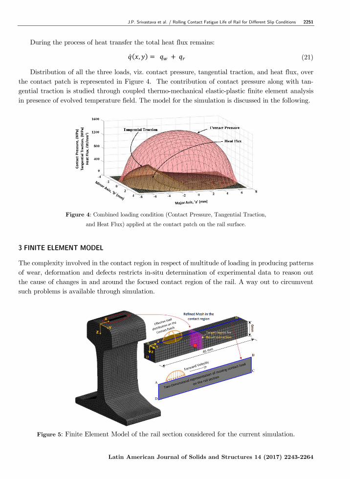
During the process of heat transfer the total heat flux remains:
, (21)
Distribution of all the three loads, viz. contact pressure, tangential traction, and heat flux, over the contact patch is represented in Figure 4. The contribution of contact pressure along with tan-gential traction is studied through coupled thermo-mechanical elastic-plastic finite element analysis in presence of evolved temperature field. The model for the simulation is discussed in the following.
Figure 4: Combined loading condition (Contact Pressure, Tangential Traction,
and Heat Flux) applied at the contact patch on the rail surface.
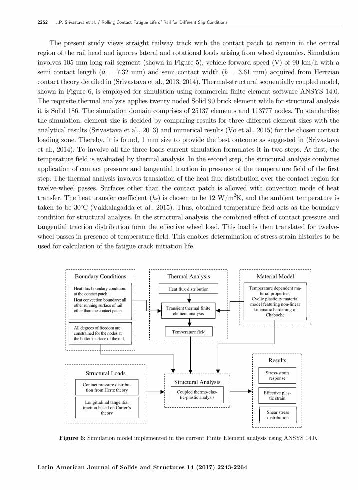
3 FINITE ELEMENT MODEL
The complexity involved in the contact region in respect of multitude of loading in producing patterns of wear, deformation and defects restricts in-situ determination of experimental data to reason out the cause of changes in and around the focused contact region of the rail. A way out to circumvent such problems is available through simulation.
Figure 5: Finite Element Model of the rail section considered for the current simulation.
2252 J.P. Srivastava et al. / Rolling Contact Fatigue Life of Rail for Different Slip Conditions
Latin American Journal of Solids and Structures 14 (2017) 2243-2264
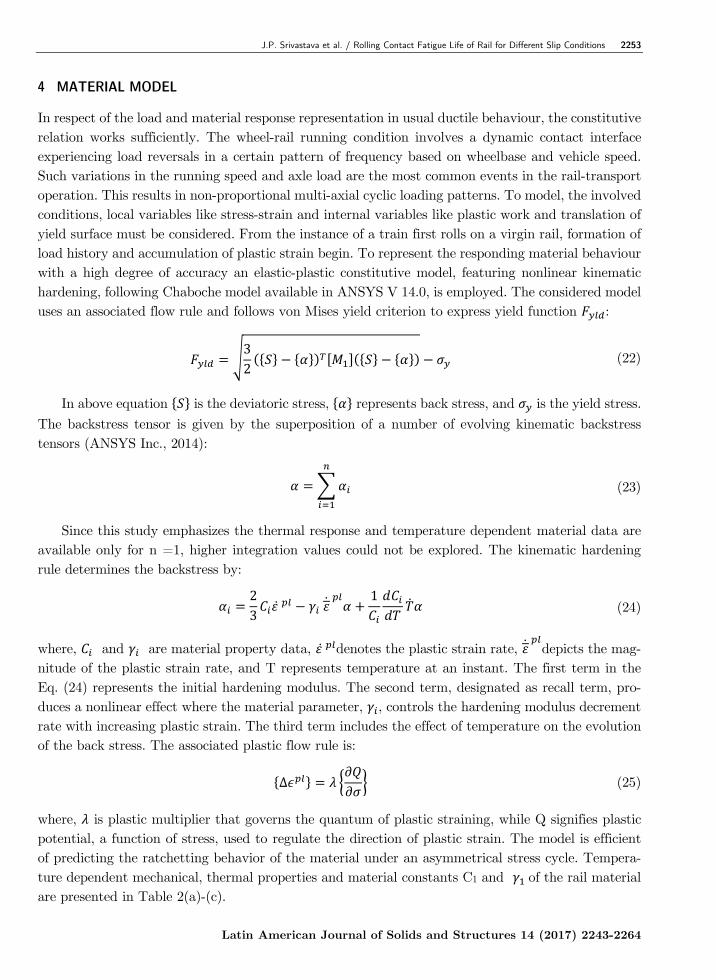
The present study views straight railway track with the contact patch to remain in the central region of the rail head and ignores lateral and rotational loads arising from wheel dynamics. Simulation involves 105 mm long rail segment (shown in Figure 5), vehicle forward speed (V) of 90 km/h with a semi contact length ( = 7.32 mm) and semi contact width (b = 3.61 mm) acquired from Hertzian contact theory detailed in (Srivastava et al., 2013, 2014). Thermal-structural sequentially coupled model, shown in Figure 6, is employed for simulation using commercial finite element software ANSYS 14.0. The requisite thermal analysis applies twenty noded Solid 90 brick element while for structural analysis it is Solid 186. The simulation domain comprises of 25137 elements and 113777 nodes. To standardize the simulation, element size is decided by comparing results for three different element sizes with the analytical results (Srivastava et al., 2013) and numerical results (Vo et al., 2015) for the chosen contact loading zone. Thereby, it is found, 1 mm size to provide the best outcome as suggested in (Srivastava et al., 2014). To involve all the three loads current simulation formulates it in two steps. At first, the temperature field is evaluated by thermal analysis. In the second step, the structural analysis combines application of contact pressure and tangential traction in presence of the temperature field of the first step. The thermal analysis involves translation of the heat flux distribution over the contact region for twelve-wheel passes. Surfaces other than the contact patch is allowed with convection mode of heat transfer. The heat transfer coefficient (hc) is chosen to be 12 W/m2K, and the ambient temperature is taken to be 30°C (Vakkalagadda et al., 2015). Thus, obtained temperature field acts as the boundary condition for structural analysis. In the structural analysis, the combined effect of contact pressure and tangential traction distribution form the effective wheel load. This load is then translated for twelve-wheel passes in presence of temperature field. This enables determination of stress-strain histories to be used for calculation of the fatigue crack initiation life.
Figure 6: Simulation model implemented in the current Finite Element analysis using ANSYS 14.0.
Transient thermal finite element analysis
Temperature field
Heat flux distribution
Thermal Analysis
All degrees of freedom are constrained for the nodes at the bottom surface of the rail.
Heat flux boundary condition: at the contact patch,
Heat convection boundary: all other running surface of rail other than the contact patch.
Boundary Conditions
Longitudinal tangential traction based on Carter’s
theory
Structural Loads
Contact pressure distribu-tion from Hertz theory
Effective plas-tic strain
Shear stress distribution
Stress-strain response
Results
Structural Analysis Coupled thermo-elas-
tic-plastic analysis
Temperature dependent ma-
terial properties, Cyclic plasticity material
model featuring non-linear kinematic hardening of
Chaboche
Material Model
J.P. Srivastava et al. / Rolling Contact Fatigue Life of Rail for Different Slip Conditions 2253
Latin American Journal of Solids and Structures 14 (2017) 2243-2264
4 MATERIAL MODEL
In respect of the load and material response representation in usual ductile behaviour, the constitutive relation works sufficiently. The wheel-rail running condition involves a dynamic contact interface experiencing load reversals in a certain pattern of frequency based on wheelbase and vehicle speed. Such variations in the running speed and axle load are the most common events in the rail-transport operation. This results in non-proportional multi-axial cyclic loading patterns. To model, the involved conditions, local variables like stress-strain and internal variables like plastic work and translation of yield surface must be considered. From the instance of a train first rolls on a virgin rail, formation of load history and accumulation of plastic strain begin. To represent the responding material behaviour with a high degree of accuracy an elastic-plastic constitutive model, featuring nonlinear kinematic hardening, following Chaboche model available in ANSYS V 14.0, is employed. The considered model uses an associated flow rule and follows von Mises yield criterion to express yield function :
32
(22)
In above equation is the deviatoric stress, represents back stress, and is the yield stress. The backstress tensor is given by the superposition of a number of evolving kinematic backstress tensors (ANSYS Inc., 2014):
(23)
Since this study emphasizes the thermal response and temperature dependent material data are available only for n =1, higher integration values could not be explored. The kinematic hardening rule determines the backstress by:
23
1
(24)
where, and are material property data, denotes the plastic strain rate,
depicts the mag-nitude of the plastic strain rate, and T represents temperature at an instant. The first term in the Eq. (24) represents the initial hardening modulus. The second term, designated as recall term, pro-duces a nonlinear effect where the material parameter, , controls the hardening modulus decrement rate with increasing plastic strain. The third term includes the effect of temperature on the evolution of the back stress. The associated plastic flow rule is:
∆ (25)
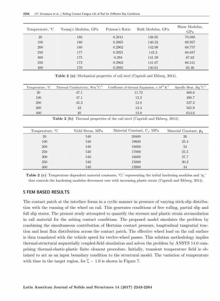
where, is plastic multiplier that governs the quantum of plastic straining, while Q signifies plastic potential, a function of stress, used to regulate the direction of plastic strain. The model is efficient of predicting the ratchetting behavior of the material under an asymmetrical stress cycle. Tempera-ture dependent mechanical, thermal properties and material constants C1 and of the rail material are presented in Table 2(a)-(c).
2254 J.P. Srivastava et al. / Rolling Contact Fatigue Life of Rail for Different Slip Conditions
Latin American Journal of Solids and Structures 14 (2017) 2243-2264
Temperature, °C Young’s Modulus, GPa Poisson’s Ratio Bulk Modulus, GPa Shear Modulus,
GPa 20 180 0.2841 138.95 70.088 100 180 0.2865 140.52 69.957 200 180 0.2902 142.99 69.757 250 177 0.2921 142.3 68.687 300 175 0.294 141.59 67.62 350 172 0.2962 141.07 66.541 400 170 0.2985 140.61 65.46
Table 2 (a): Mechanical properties of rail steel (Caprioli and Ekberg, 2014).
Temperature, °C Thermal Conductivity, Wm-1C-1 Coefficient of thermal Expansion, x 10-6 K-1 Specific Heat, Jkg-1C-1
20 47.1 11.72 468.6 100 47.1 12.2 490.7 200 45.3 12.8 527.2 300 43 13.4 565.9 400 40 13.8 614.6
Table 2 (b): Thermal properties of the rail steel (Caprioli and Ekberg, 2014).
Temperature, °C Yield Stress, MPa Material Constant, C1, MPa Material Constant,
20 540 20800 26 100 540 19600 25.4 200 540 18000 24 250 540 17000 25.5 300 540 16000 27.7 350 540 15000 30.2 400 540 13900 34
Table 2 (c): Temperature dependent material constants, ‘C1’ representing the initial hardening modulus and ‘ ’ that controls the hardening modulus decrement rate with increasing plastic strain (Caprioli and Ekberg, 2014).
5 FEM BASED RESULTS
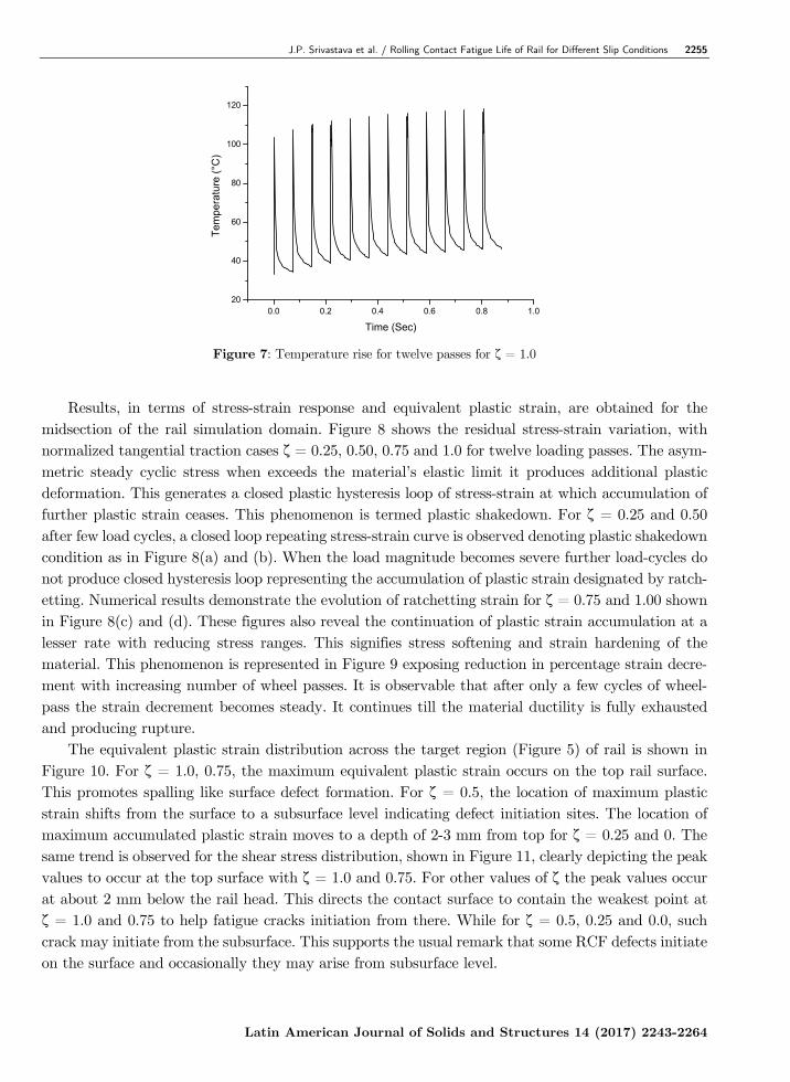
The contact patch at the interface forms in a cyclic manner in presence of varying stick-slip distribu-tion with the running of the wheel on rail. This generates conditions of free rolling, partial slip and full slip states. The present study attempted to quantify the stresses and plastic strain accumulation in rail material for the arising contact conditions. The proposed model simulates the problem by combining the simultaneous contribution of Hertzian contact pressure, longitudinal tangential trac-tion and heat flux distribution across the contact patch. The effective wheel load on the rail surface is then translated with the vehicle speed for twelve-wheel passes. This solution methodology implies thermal-structural sequentially coupled-field simulation and solves the problem by ANSYS 14.0 com-prising thermal-elastic-plastic finite element procedure. Initially, transient temperature field is ob-tained to act as an input boundary condition to the structural model. The variation of temperature with time in the target region, for ζ = 1.0 is shown in Figure 7.
J.P. Srivastava et al. / Rolling Contact Fatigue Life of Rail for Different Slip Conditions 2255
Latin American Journal of Solids and Structures 14 (2017) 2243-2264
0.0 0.2 0.4 0.6 0.8 1.020
40
60
80
100
120
Tem
pera
ture
(°C
)
Time (Sec)
Figure 7: Temperature rise for twelve passes for ζ = 1.0
Results, in terms of stress-strain response and equivalent plastic strain, are obtained for the
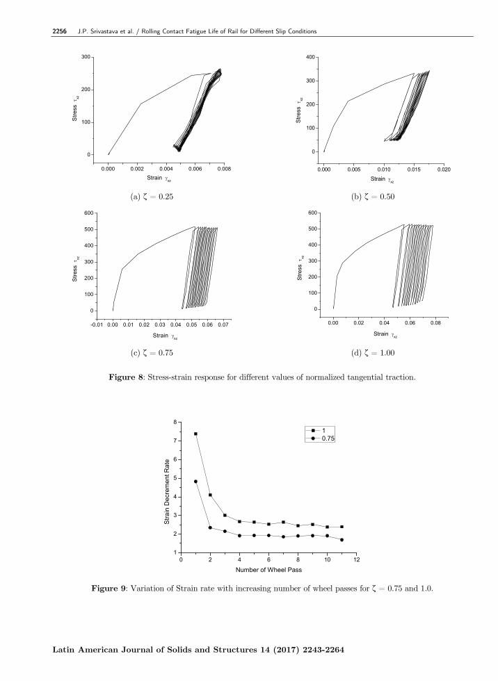
midsection of the rail simulation domain. Figure 8 shows the residual stress-strain variation, with normalized tangential traction cases ζ = 0.25, 0.50, 0.75 and 1.0 for twelve loading passes. The asym-metric steady cyclic stress when exceeds the material’s elastic limit it produces additional plastic deformation. This generates a closed plastic hysteresis loop of stress-strain at which accumulation of further plastic strain ceases. This phenomenon is termed plastic shakedown. For ζ = 0.25 and 0.50 after few load cycles, a closed loop repeating stress-strain curve is observed denoting plastic shakedown condition as in Figure 8(a) and (b). When the load magnitude becomes severe further load-cycles do not produce closed hysteresis loop representing the accumulation of plastic strain designated by ratch-etting. Numerical results demonstrate the evolution of ratchetting strain for ζ = 0.75 and 1.00 shown in Figure 8(c) and (d). These figures also reveal the continuation of plastic strain accumulation at a lesser rate with reducing stress ranges. This signifies stress softening and strain hardening of the material. This phenomenon is represented in Figure 9 exposing reduction in percentage strain decre-ment with increasing number of wheel passes. It is observable that after only a few cycles of wheel-pass the strain decrement becomes steady. It continues till the material ductility is fully exhausted and producing rupture.
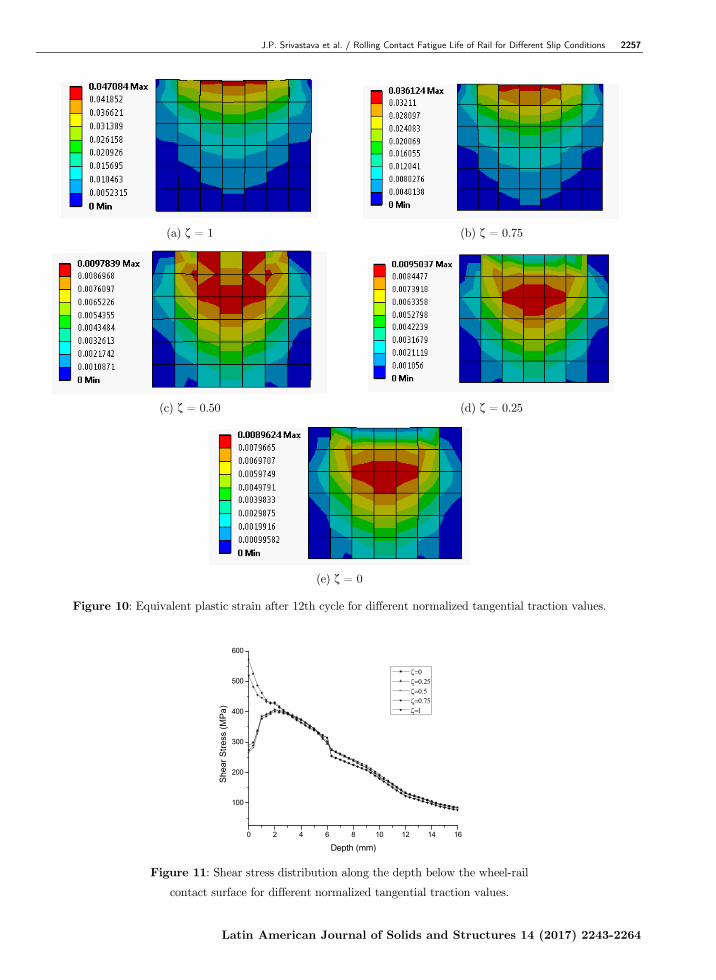
The equivalent plastic strain distribution across the target region (Figure 5) of rail is shown in Figure 10. For ζ = 1.0, 0.75, the maximum equivalent plastic strain occurs on the top rail surface. This promotes spalling like surface defect formation. For ζ = 0.5, the location of maximum plastic strain shifts from the surface to a subsurface level indicating defect initiation sites. The location of maximum accumulated plastic strain moves to a depth of 2-3 mm from top for ζ = 0.25 and 0. The same trend is observed for the shear stress distribution, shown in Figure 11, clearly depicting the peak values to occur at the top surface with ζ = 1.0 and 0.75. For other values of ζ the peak values occur at about 2 mm below the rail head. This directs the contact surface to contain the weakest point at ζ = 1.0 and 0.75 to help fatigue cracks initiation from there. While for ζ = 0.5, 0.25 and 0.0, such crack may initiate from the subsurface. This supports the usual remark that some RCF defects initiate on the surface and occasionally they may arise from subsurface level.
2256 J.P. Srivastava et al. / Rolling Contact Fatigue Life of Rail for Different Slip Conditions
Latin American Journal of Solids and Structures 14 (2017) 2243-2264
0
100
200
300
0.000 0.002 0.004 0.006 0.008Strain xz
Stre
ss
xz
0
100
200
300
400
0.000 0.005 0.010 0.015 0.020
Strain xz
Stre
ss
xz
(a) ζ = 0.25 (b) ζ = 0.50
-0.01 0.00 0.01 0.02 0.03 0.04 0.05 0.06 0.07
0
100
200
300
400
500
600
Stre
ss
xz
Strain xz
0.00 0.02 0.04 0.06 0.08
0
100
200
300
400
500
600
Strain xz
Stre
ss
xz
(c) ζ = 0.75 (d) ζ = 1.00
Figure 8: Stress-strain response for different values of normalized tangential traction.
0 2 4 6 8 10 121
2
3
4
5
6
7
8
Stra
in D
ecre
men
t Rat
e
Number of Wheel Pass
1 0.75
Figure 9: Variation of Strain rate with increasing number of wheel passes for ζ = 0.75 and 1.0.
J.P. Srivastava et al. / Rolling Contact Fatigue Life of Rail for Different Slip Conditions 2257
Latin American Journal of Solids and Structures 14 (2017) 2243-2264
(a) ζ = 1 (b) ζ = 0.75
(c) ζ = 0.50 (d) ζ = 0.25
(e) ζ = 0
Figure 10: Equivalent plastic strain after 12th cycle for different normalized tangential traction values.
0 2 4 6 8 10 12 14 16
100
200
300
400
500
600
Shea
r Stre
ss (M
Pa)
Depth (mm)
Figure 11: Shear stress distribution along the depth below the wheel-rail
contact surface for different normalized tangential traction values.
2258 J.P. Srivastava et al. / Rolling Contact Fatigue Life of Rail for Different Slip Conditions
Latin American Journal of Solids and Structures 14 (2017) 2243-2264
6 ROLLING CONTACT FATIGUE MODEL
Aperiodic cyclic contact of the wheel on rail produce a non-proportional multiaxial stress-strain re-sponse to cause fatigue damage of the rail. While proportional loading signifies fixed principal stress direction with loading axis, for a given loading cycle, non-proportional loading causes the orientation of principal stress axes to change continuously. The change in the orientation of principal stress axes permits more grains to align in their most favourable orientations for slip and increases the interaction between slip systems. This induces additional cyclic hardening of material with reduced fatigue life. Multiaxial fatigue models help to reduce the complexity involved in multi axial loading conditions. Chen et al. (2011) categorized the multiaxial fatigue models to be based on stress-strain approach, energy approach and critical plane approach. Findley and Coleman (1956) described the plane sub-jected to the largest cycle of shear stress as the critical plane. Fatemi and Socie (1988) stated the critical plane to be the plane linked with the maximum shear strain amplitude. Smith et al. (1970) proposed a SWT Parameter deduced only from normal components of stress and strain to predict the fatigue life to crack initiation. Thus, for non-proportional (complex) loading conditions, SWT model may predict unrealistic fatigue crack initiation life. A combined approach based on the energy density and critical plane for low cycle fatigue problems by Jiang and Sehitoglu (1999) is used to predict the fatigue life. This approach is strongly dependent on the stress state, loading histories and material type. In this criterion, it combines both normal and shear components of stress and strain on the critical plane to contribute to the damage of the material.
The time histories of the stress-strain fields, for different rolling-sliding conditions, obtained from the finite element analyses are implemented in the multiaxial fatigue model of Jiang and Sehitoglu (1999) to obtain the fatigue crack initiation life. The material point giving maximum von Mises stress is taken as the critical location denoting the crack initiation site. Accordingly, present study forms its solution strategy to determine the critical plane by incorporating residual normal strain range ∆ , residual shear strain range ∆ , residual shear stress range ∆ , and maximum normal stress σmax. These range values are obtained by surfing the stress and strain histories on all the planes through the critical location. Jiang (Jiang, 2000) and Glinka et al. (1995) clarified J in Eq. (26) to be a ratio of applied shear strain range in the critical plane to the normal strain range in the same plane. Its value for pure tension is zero and infinity for pure shear. In mixed state, its magnitude will assume values between 0 and ∞. For the material and loading conditions in Jiang and Sehitoglu (1999), J = 0.25 is used in this analysis.
∆2
∆ ∆ (26)
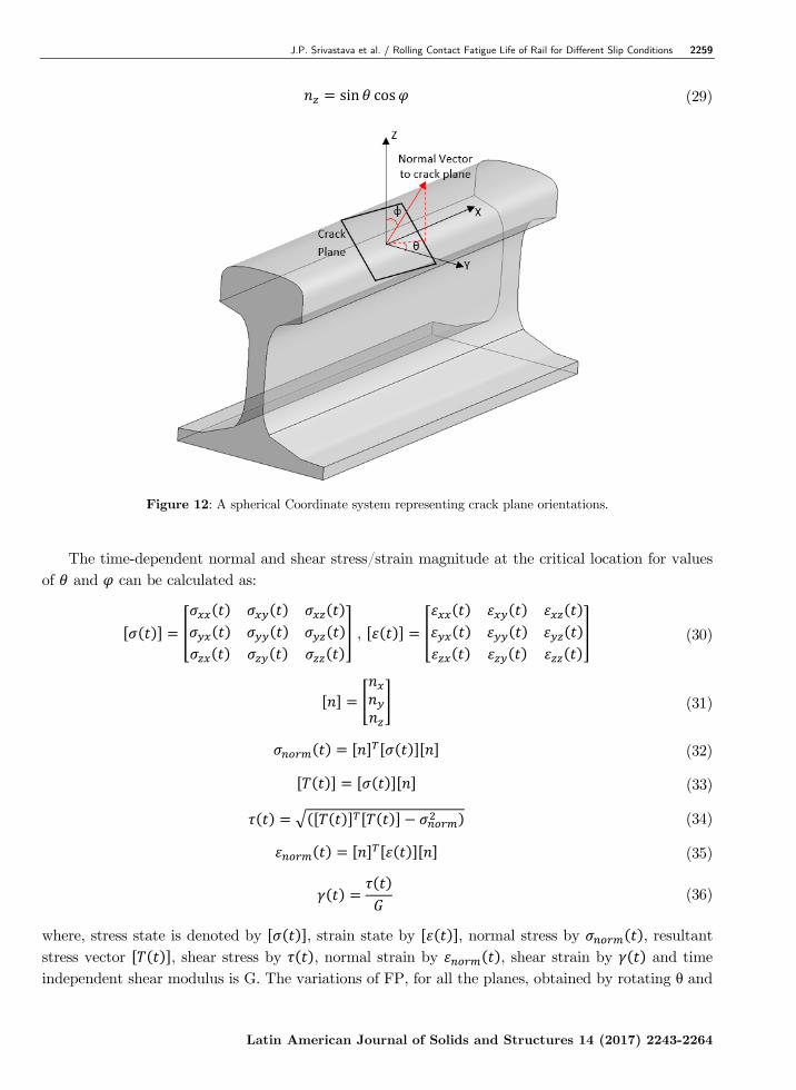
Eq. (26) evaluates the fatigue parameter. On a plane, this FP becomes maximum. Jiang and Sehitoglu (1999) defines this as a critical plane. Different orientations of the plane are achieved by varying the values of θ [0°, 360°] and φ [0°, 180°] shown in Figure 12. Direction cosines of the planes are given by Eq. 27-29.
sin sin (27)
cos (28)
J.P. Srivastava et al. / Rolling Contact Fatigue Life of Rail for Different Slip Conditions 2259
Latin American Journal of Solids and Structures 14 (2017) 2243-2264
sin cos (29)
Figure 12: A spherical Coordinate system representing crack plane orientations.
The time-dependent normal and shear stress/strain magnitude at the critical location for values
of and can be calculated as:
, (30)
(31)
(32)
(33)
(34)
(35)
(36)
where, stress state is denoted by , strain state by , normal stress by , resultant stress vector , shear stress by , normal strain by , shear strain by and time independent shear modulus is G. The variations of FP, for all the planes, obtained by rotating θ and
2260 J.P. Srivastava et al. / Rolling Contact Fatigue Life of Rail for Different Slip Conditions
Latin American Journal of Solids and Structures 14 (2017) 2243-2264
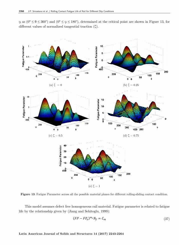
φ as (0° ≤ θ ≤ 360°) and (0° ≤ φ ≤ 180°), determined at the critical point are shown in Figure 13, for different values of normalized tangential traction (ζ).
(a) ζ = 0 (b) ζ = 0.25
(c) ζ = 0.5 (d) ζ = 0.75
(e) ζ = 1
Figure 13: Fatigue Parameter across all the possible material planes for different rolling-sliding contact condition.
This model assumes defect free homogeneous rail material. Fatigue parameter is related to fatigue
life by the relationship given by (Jiang and Sehitoglu, 1999):
(37)
J.P. Srivastava et al. / Rolling Contact Fatigue Life of Rail for Different Slip Conditions 2261
Latin American Journal of Solids and Structures 14 (2017) 2243-2264
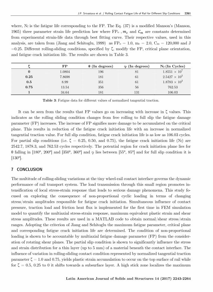
where, Nf is the fatigue life corresponding to the FP. The Eq. (37) is a modified Manson’s (Manson, 1965) three parameter strain life prediction law where FPo , and are constants determined from experimental strain-life data through best fitting curve. Their respective values, used in this analysis, are taken from (Jiang and Sehitoglu, 1999) as FPo = 1.0, mc = 2.0, Cm = 120,000 and J =0.25. Different rolling-sliding conditions, specified by ζ, modify the FP, critical plane orientation, and fatigue crack initiation life. The results are shown in Table 3.
ζ FP θ (In degrees) φ (In degrees) Nf (In Cycles) 0 1.0804 196 81 1.8551 × 10⁷
0.25 7.8698 181 61 2.5427 × 10³ 0.5 8.99 351 61 1.8783 × 10³ 0.75 13.54 356 56 762.53 1 34.64 181 131 106.03
Table 3: Fatigue data for different values of normalized tangential traction.
It can be seen from the results that FP values go on increasing with increase in ζ values. This
indicates as the rolling sliding condition changes from free rolling to full slip the fatigue damage parameter (FP) increases. The increase of FP signifies more damage to be accumulated on the critical plane. This results in reduction of the fatigue crack initiation life with an increase in normalized tangential traction value. For full slip condition, fatigue crack initiation life is as low as 106.03 cycles. For partial slip conditions (i.e. ζ = 0.25, 0.50, and 0.75), the fatigue crack initiation life (Nf) are 2542.7, 1878.3, and 762.53 cycles respectively. The potential region for crack initiation plane lies for θ falling in [180°, 200°] and [350°, 360°] and φ lies between [55°, 85°] and for full slip condition it is [130°]. 7 CONCLUSION
The multitude of rolling-sliding variations at the tiny wheel-rail contact interface governs the dynamic performance of rail transport system. The load transmission through this small region promotes in-tensification of local stress-strain response that leads to serious damage phenomena. This study fo-cused on exploring the consequence of non-proportional cyclic loading in terms of changing stress/strain amplitudes responsible for fatigue crack initiation. Simultaneous influence of contact pressure, traction load and friction heat flux is implemented for the first time in FEM simulation model to quantify the multiaxial stress-strain response, maximum equivalent plastic strain and shear stress amplitudes. These results are used in a MATLAB code to obtain normal/shear stress/strain ranges. Adopting the criterion of Jiang and Sehitoglu the maximum fatigue parameter, critical plane and corresponding fatigue crack initiation life are determined. The condition of non-proportional loading is shown to be accountable by multiaxial fatigue damage parameter (FP) from the consider-ation of rotating shear planes. The partial slip condition is shown to significantly influence the stress and strain distribution for a thin layer (up to 5 mm) of a material beneath the contact interface. The influence of variation in rolling-sliding contact condition represented by normalized tangential traction parameter ζ = 1.0 and 0.75, yields plastic strain accumulation to occur on the top surface of rail while for ζ = 0.5, 0.25 to 0 it shifts towards a subsurface layer. A high stick zone localizes the maximum
2262 J.P. Srivastava et al. / Rolling Contact Fatigue Life of Rail for Different Slip Conditions
Latin American Journal of Solids and Structures 14 (2017) 2243-2264
shear stress and strain to lie at the contact surface. These results specify the conditions responsible for fatigue crack to originate from the outer surface or a subsurface point. The outcome of this study exposed the onset of ratchetting behaviour from higher values of normalized tangential traction (Fig-ures 8(c) and (d)). The study envisages utilization of the discussed method and findings to help improve the material design and the maintenance strategy for safer and comfortable rail transport operation. References
Ahlström, J. (2016). Residual stresses generated by repeated local heating events – Modelling of possible mechanisms for crack initiation. Wear, 366–367: 180–187. https://doi.org/10.1016/j.wear.2016.05.029
ANSYS Inc. (2014). ANSYS Mechanical User’s Guide (Vol. 15317).
Caprioli, S., and Ekberg, A. (2014). Numerical evaluation of the material response of a railway wheel under thermo-mechanical braking conditions. Wear, 314: 181–188. https://doi.org/10.1016/j.wear.2013.11.022
Carroll, R. I. (2005). Surface Metallurgy and Rolling Contact Fatigue of Rail. PhD Thesis, The University of Sheffield, UK.
Carter, F. W. (1926). On the action of locomotive driving wheel. Proc. R. Soc. London, Ser. A, 112: 151–157.
Chen, H., Shang, D.-G., Bao, M. (2011). Selection of multiaxial fatigue damage model based on the dominated loading modes. International Journal of Fatigue, 33(5): 735–739. https://doi.org/10.1016/j.ijfatigue.2010.12.006
Ekberg, A., and Sotkovszki, P. (2001). Anisotropy and rolling contact fatigue of railway wheels. International Journal of Fatigue, 23(1): 29–43. https://doi.org/10.1016/S0142-1123(00)00070-0
Fatemi, A., and Socie, D. F. (1988). A critical plane approach to multiaxial fatigue damage including out of phase loading. Fatigue & Fracture of Engineering Materials & Structures, 11(3): 149–165. https://doi.org/10.1111/j.1460-2695.1988.tb01169.x
Findley, W., and Coleman, J. (1956). Theory for combined bending and torsion fatigue with data for 4030 steel. In Proceedings of the International Conference on Fatigue of Metals. London, England: Institution of Mechanical Engi-neers.
Glinka, G., Shen, G., Plumtree, A. (1995). A Multiaxial Fatigue Strain Energy Density Parameter Related To the Critical Fracture Plane. Fatigue & Fracture of Engineering Materials & Structures, 18(1): 37–46. https://doi.org/10.1111/j.1460-2695.1995.tb00140.x
Grassie, S. L., and Johnson, K. L. (1985). Periodic microslip between a rolling wheel and a corrugated rail. Wear, 101: 291–309. https://doi.org/10.1016/0043-1648(85)90134-6
Haidari A., and Tehranib, P. H. (2015). Thermal load effects on fatigue life of a cracked railway wheel. Latin American Journal of Solids and Structures, 12: 1144–1157. https://dx.doi.org/10.1590/1679-78251658
Haines, D. J., and Ollerton, E. (1963). Contact Stress Distributions on Elliptical Contact Surfaces Subjected to Radial and Tangential Forces. Proceedings of the Institution of Mechanical Engineers, 177(1): 95–114. https://doi.org/10.1243/PIME_PROC_1963_177_014_02
Jiang, Y., and Sehitoglu, H. (1999). A model for rolling contact failure. Wear, 224(1): 38–49. https://doi.org/10.1016/S0043-1648(98)00311-1
Jiang, Y. (2000). Fatigue criterion for general multiaxial loading. Fatigue and Fracture of Engineering Materials and Structures, 23(1): 19–32. https://doi.org/10.1046/j.1460-2695.2000.00247.x
Kennedy, T. C., Plengsaard, C., Harder, R. F. (2006). Transient heat partition factor for a sliding railcar wheel. Wear, 261(7–8): 932–936. https://doi.org/10.1016/j.wear.2006.01.016
Makino, T., Kato, T., Hirakawa, K. (2012). The effect of slip ratio on the rolling contact fatigue property of railway wheel steel. International Journal of Fatigue, 36(1): 68–79. https://doi.org/10.1016/j.ijfatigue.2011.08.014
J.P. Srivastava et al. / Rolling Contact Fatigue Life of Rail for Different Slip Conditions 2263
Latin American Journal of Solids and Structures 14 (2017) 2243-2264
Manson, S. S. (1965). Fatigue: A Complex Subject- Some Simple Approximations. Experimental Mechanics, 5(4): 193–226. https://doi.org/10.1007/BF02321056
Paul, B. (1975). A Review of rail—wheel contact stress problems. In Railroad Track Mechanics and Technology (pp. 323–351). held at Princeton University, April 21 - 23. https://doi.org/10.1016/B978-0-08-021923-3.50021-8
Pun, C. L., Kan, Q., Mutton, P. J., Kang, G., Yan, W. (2015). An efficient computational approach to evaluate the ratcheting performance of rail steels under cyclic rolling contact in service. International Journal of Mechanical Sciences, 101–102: 214–226. https://doi.org/10.1016/j.ijmecsci.2015.08.008
Reis, L., Li, B., de Freitas, M. (2014). A multiaxial fatigue approach to Rolling Contact Fatigue in railways. Interna-tional Journal of Fatigue, 67: 191-202. https://doi.org/10.1016/j.ijfatigue.2014.02.001
Ringsberg, J. W., Bjarnehed, H., Johansson, A., Josefson, B. L. (2000). Rolling contact fatigue of rails—finite element modelling of residual stresses, strains and crack initiation. Proceedings of the Institution of Mechanical Engineers, Part F: Journal of Rail and Rapid Transit, 214(1): 7–19. https://doi.org/10.1243/0954409001531207
Ringsberg, J. W. (2001). Life prediction of rolling contact fatigue crack initiation. International Journal of Fatigue, 23(7): 575–586. https://doi.org/10.1016/S0142-1123(01)00024-X
Ringsber, J. W., and Josefson, B. L. (2001). Finite element analyses of rolling contact fatigue crack initiation in railheads. Proceedings of the Institution of Mechanical Engineers, Part F: Journal of Rail and Rapid Transit, 215(4): 243–259. https://doi.org/10.1243/0954409011531558
Ringsberg, J. W. (2003). Rolling contact fatigue analysis of rails inculding numerical simulations of the rail manufac-turing process and repeated wheel-rail contact loads. International Journal of Fatigue, 25(6): 547–558. https://doi.org/10.1016/S0142-1123(02)00147-0
Sciammarella, C. A., Chen, R. J. S., Gallo, P., Berto, F., Lamberti, L. (2016). Experimental evaluation of rolling contact fatigue in railroad wheels. International Journal of Fatigue, 91: 158–170. https://doi.org/10.1016/j.ijfa-tigue.2016.05.035
Smith, K. N., Topper, T. H., Watson, P. (1970). A stress-strain function for the fatigue of metals (Stress-strain function for metal fatigue including mean stress effect). Journal of Materials, 5: 767–778.
Sraml, M., Flasker, J., Potrc, I. (2003). Numerical procedure for predicting the rolling contact fatigue crack initiation. International Journal of Fatigue, 25(7): 585–595. https://doi.org/10.1016/S0142-1123(03)00019-7
Srivastava, J. P., Sarkar, P. K., Ranjan, V. (2013). An Approximate Analysis for Hertzian Elliptical Wheel-Rail Contact Problem. In Proceedings of the 1st International and 16th National Conference on Machines and Mechanisms (iNaCoMM2013) (pp. 249–253). Roorkee.
Srivastava, J. P., Sarkar, P. K., Ranjan, V. (2014). Contact Stress Analysis in Wheel–Rail by Hertzian Method and Finite Element Method. Journal of The Institution of Engineers (India): Series C, 95(4): 319–325. https://doi.org/10.1007/s40032-014-0145-x
Tyfour, W. R., and Beynon, J. H. (1994). The effect of rolling direction reversal on the wear rate and wear mechanism of pearlitic rail steel. Tribology International, 27(6): 401–412. https://doi.org/10.1016/0301-679X(94)90017-5
Vakkalagadda, M. R. K., Vineesh, K. P., Racherla, V. (2015). Estimation of railway wheel running temperatures using a hybrid approach. Wear, 328–329: 537–551. https://doi.org/10.1016/j.wear.2015.03.026
Vo, K. D., Tieu, A. K., Zhu, H. T., Kosasih, P. B. (2015). The influence of high temperature due to high adhesion condition on rail damage. Wear, 330–331: 571–580. https://doi.org/10.1016/j.wear.2015.01.059
Wei, Li, Zefeng, W., Xuesong, J., Lei, W. (2014). Numerical analysis of rolling sliding contact with thw frictional heat in rail. Chinese Journal of Mechanical Engineering, 27(1): 41-49. https://doi.org/10.3901/CJME.2014.01.041
Widiyarta, I. M., Franklin, F. J., Kapoor, A. (2008). Modelling thermal effects in ratcheting-led wear and rolling contact fatigue. Wear, 265(9–10): 1325–1331. https://doi.org/10.1016/j.wear.2008.02.026
Xu, B., and Jiang, Y. (2002). Elastic-Plastic Finite Element Analysis of Nonsteady State Partial Slip Wheel-Rail Rolling Contact. Journal of Tribology, 124(1): 20–26. https://doi.org/10.1115/1.1395630
2264 J.P. Srivastava et al. / Rolling Contact Fatigue Life of Rail for Different Slip Conditions
Latin American Journal of Solids and Structures 14 (2017) 2243-2264
Zwierczyk, P. T., and Váradi, K. (2014). Thermal Stress Analysis of a Railway Wheel in Sliding-Rolling Motion. Journal of Tribology, 136(3): 31401. https://doi.org/10.1115/1.4027544
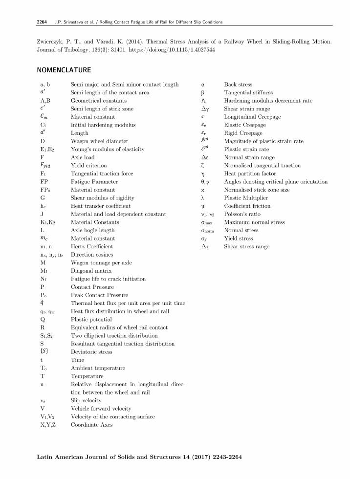
NOMENCLATURE
a, b Semi major and Semi minor contact length α Back stress Semi length of the contact area β Tangential stiffness
A,B Geometrical constants Hardening modulus decrement rate Semi length of stick zone Δγ Shear strain range Material constant Longitudinal Creepage
Ci Initial hardening modulus Elastic Creepage Length Rigid Creepage
D Wagon wheel diameter ̅ Magnitude of plastic strain rate E1,E2 Young’s modulus of elasticity Plastic strain rate F Axle load Δε Normal strain range
Yield criterion ζ Normalised tangential traction Ft Tangential traction force η Heat partition factor FP Fatigue Parameter θ,φ Angles denoting critical plane orientationFPo Material constant κ Normalised stick zone size G Shear modulus of rigidity λ Plastic Multiplier hc Heat transfer coefficient µ Coefficient friction J Material and load dependent constant ν1, ν2 Poisson’s ratio K1,K2 Material Constants σmax Maximum normal stress L Axle bogie length σnorm Normal stress
Material constant σy Yield stress m, n Hertz Coefficient Δτ Shear stress range nx, ny, nz Direction cosines M Wagon tonnage per axle M1 Diagonal matrix Nf Fatigue life to crack initiation P Contact Pressure Po Peak Contact Pressure Thermal heat flux per unit area per unit time
qr, qw Heat flux distribution in wheel and rail Q Plastic potential R Equivalent radius of wheel rail contact S1,S2 Two elliptical traction distribution S Resultant tangential traction distribution
Deviatoric stress t Time To Ambient temperature T Temperature u Relative displacement in longitudinal direc-
tion between the wheel and rail
vs Slip velocity V Vehicle forward velocity V1,V2 Velocity of the contacting surface X,Y,Z Coordinate Axes