mono rail - bibus menos · small differential slip in comparison to 4-point contact very quiet...
TRANSCRIPT

MONO RAIL
www.rollon.com
About Rollon
Continual expansion and optimization of the portfolio
Founded in 1975, Rollon manufactured high-precision linear roller bea-
rings for the machine tool industry. Early on, Rollon started manufacturing
linear bearings based on the bearing-cage design. In 1979, the Com-
pact Rail self-aligning linear bearings joined the Telescopic Rail indus-
trial drawer slides and Easy Rail linear bearings and became the basis
of the strong foundation on which the company is building upon today.
Continuing optimization of these core products still remains one of the
most important goals at Rollon. The development of the patented Compact
Rail linear bearing, which uses different proprietary rail profiles and high-
precision radial ball bearing sliders, enables the compensation of height
and angle mounting defects in applications, and is only one example of
the continuing efforts to innovative the development of our existing pro-
duct families. In the same manner, we continually introduce innovative
new product familiesdisplaying our continuing product development and
optimization in the industry. These include:
■ 1994 Light Rail - full and partial extension telescopic in lightweight
design
■ 1996 Uniline - belt driven linear actuators
■ 2001 Ecoline - economical aluminum linear actuators
■ 2002 X-Rail - inexpensive formed steel linear guides
■ 2004 Curviline - curved monorail profile rail guide with roller carriages
■ 2007 Monorail - miniature sizes and full sized
Each further innovation of our linear bearings is built upon the our exten-
sive knowledge of the nine product families in production today as well as
on the current market demands. Rollon is the ultimate linear technology
for any application needs.
Development of global business
1975 Parent company, Rollon S.r.l., founded in Italy
1991 Founding of Rollon GmbH in Germany
1995 Expansion of headquarters to new 4,000 m2 factory
Assembly starts in Germany
Quality management certified to ISO 9001
1998 Rollon B.V. in the Netherlands and Rollon Corporation in the
USA are founded
Expansion of German branch to new 1,000 m2 plant
1999 Founding of Rollon S.A.R.L. in France
Environmental management certified to ISO 14001
2000 Rollon s.r.o. founded in Czech Republic
2001 Expansion of headquarters to new 12,000 m2
manufacturing plant
2007 Restructuring of the GmbH and alignment of production in
Germany to customer-specific adaptations
Takeover of the assets of a manufacturer of linear rail
systems
2008 Expansion of sales network in Eastern Europe and Asia

Content
1 Product explanation Profile rails for the highest degree of precision
2 Technical data Performance characteristics and notes Load capacities
3 Product dimensions MRS series – carriage with flange MRS series – carriage without flange MRT series – carriage with flange MRT series – carriage without flange MRZ series – carriage without flange MRR...F series – rails mounted from below
5
89
10
11
12
13
14
15

Content
4 Accessories Safety equipment and covers Metal cover strip, Flush cap Clamping elements Manual clamp HK Pneumatic clamp MK / MKS Adapter plate
5 Technical instructions Precision Radial clearance / preload Anticorrosive protection, Lubrication Lubrication nipple Friction / displacement resistance Loading Service life Installation instructions Installation examples
Ordering key Ordering key with explanations and hole pattern Portfolio
161819202122
232425262728293035

5www.rollon.com
Product explanationMono Rails are profile rails for the highest degree of precision
Product explanation 1
The running grooves are ground in semicircular profile and have a contact
angle of 45° in X-arrangement so that the same load capacity is guaran-
teed in all principle directions. Use of large steel balls enables high load
and moment capacities. All carriages in size 55 are equipped with ball
chains.
The most important characteristics:
■ X-arrangement with 2-point contact of the raceways
■ Uniform loading capacity in all main directions
■ High ability for self-regulating
■ Small differential slip in comparison to 4-point contact
■ Very quiet running and low operating noise
■ Low maintenance due to advanced lubrication chamber
■ Small displacement force in preload compared to 4-point contact
■ Mono Rail profile rails meet the market standard and can replace
linear rails of the same design from other manufacturers while
maintaining the main dimensions
Preferred areas of application:
■ Construction and machine technology ( safety doors, feeding )
■ Packaging machines
■ Special purpose machinery
■ Logistics ( e.g., handling units )
■ Medical technology ( e.g., X-ray equipment, hospital gurneys )
Fig. 1

6 www.rollon.com
MRS / MRT
Standard carriage with flange in two different heights. MRT is the lower
version.
MRS...L
Carriage in long version for holding larger loads. MRS...L is the version
with flange.
MRS...LW / MRT...LW
Carriage in long version without flange. Available in two different heights.
MRT is the lower version.
MRS...W / MRZ...W / MRT...W
Carriage without flange, also called block. Available in three different
heights. MRT is the lower version; MRZ is the intermediate size.
Fig. 2
Fig.3
Fig. 4
Fig. 5
1 Product explanation
7www.rollon.com
Product explanation 1
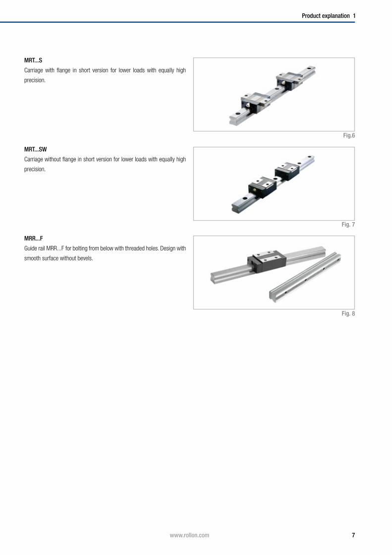
MRR...F
Guide rail MRR...F for bolting from below with threaded holes. Design with
smooth surface without bevels.
MRT...S
Carriage with flange in short version for lower loads with equally high
precision.
MRT...SW
Carriage without flange in short version for lower loads with equally high
precision.
Fig.6
Fig. 7
Fig. 8

8 www.rollon.com
2 Technical data
Technical data
Rail
Lubrication nipple
Performance characteristics:
■ Available sizes: 15, 20, 25, 30, 35, 45, 55
■ Max. operating speed: 3.5 m/s (137.79 in/s )
( depending on application )
■ Max. operating temperature: +80 °C (+176 °F )
( depending on application )
■ Available rail lengths up to approx. 4,000 mm ( 157.5 in )
( see Ordering key, Table 31)
■ Four preload classes: G1, K0, K1, K2
■ Three precision classes: N, H, P
Remarks:
■ Combining rails is possible ( joining )
■ The fixing holes on the carriages with flange can also be used as
through holes for fastening from below. Here, the reduction in size of
the screw diameter must be observed
■ Various surface coatings on request, e.g. black coating, hard chrome
plating, nickel plating
■ Manual and pneumatic clamping elements available as accessories.
Depending on the height of the carriage, additional adapter plates
must be used
■ Dimensions H2 and L of the carriage change when using metal deflec-
tors and other seals. Refer to Sec. 4 Accessories, pg. 16f
■ The carriages in size 55 are equipped with ball chains
■ Primary lubricated systems have an increased displacement resi-
stance
Side seal
Slider body
Redirection
Self-lubricating element
Fig. 9
End seal
9www.rollon.com
Technical data 2
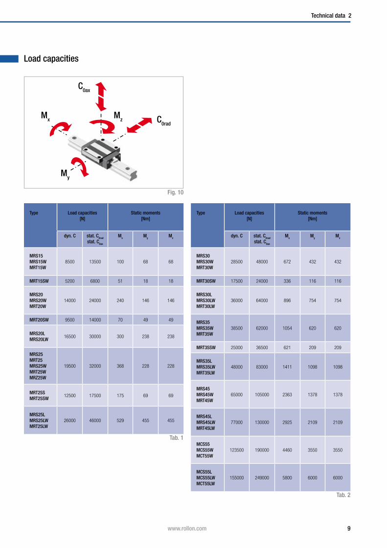
Load capacities
C0ax
C0rad
Fig. 10
Type Load capacities[N]
Static moments[Nm]
dyn. C stat. C0rad
stat. C0ax
Mx My Mz
MRS30MRS30WMRT30W
28500 48000 672 432 432
MRT30SW 17500 24000 336 116 116
MRS30LMRS30LWMRT30LW
36000 64000 896 754 754
MRS35MRS35WMRT35W
38500 62000 1054 620 620
MRT35SW 25000 36500 621 209 209
MRS35LMRS35LWMRT35LW
48000 83000 1411 1098 1098
MRS45MRS45WMRT45W
65000 105000 2363 1378 1378
MRS45LMRS45LWMRT45LW
77000 130000 2925 2109 2109
MCS55MCS55WMCT55W
123500 190000 4460 3550 3550
MCS55LMCS55LWMCT55LW
155000 249000 5800 6000 6000
Type Load capacities[N]
Static moments[Nm]
dyn. C stat. C0rad
stat. C0ax
Mx My Mz
MRS15MRS15WMRT15W
8500 13500 100 68 68
MRT15SW 5200 6800 51 18 18
MRS20MRS20WMRT20W
14000 24000 240 146 146
MRT20SW 9500 14000 70 49 49
MRS20LMRS20LW
16500 30000 300 238 238
MRS25MRT25MRS25WMRT25WMRZ25W
19500 32000 368 228 228
MRT25SMRT25SW
12500 17500 175 69 69
MRS25LMRS25LWMRT25LW
26000 46000 529 455 455
Tab. 2
Mx Mz
My
Tab. 1
10 www.rollon.com
3 Product dimensions
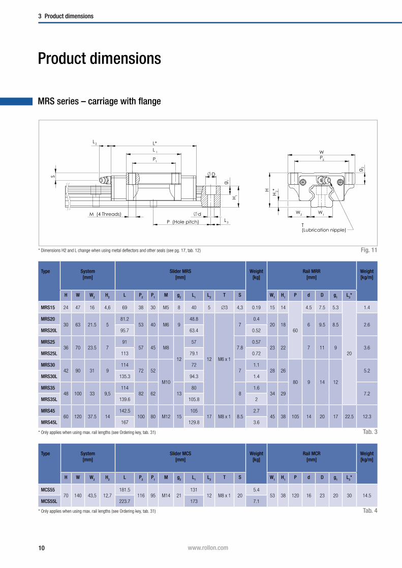
Product dimensions
MRS series – carriage with flange
P1
L 1
L*
D
g1
L 3P (Hole pitch)
d
H1
L 2
S
M (4 Threads)
P2
W
W1W2
H2*H
g2
T(Lubrication nipple)
Tab. 3
Fig. 11
Type System[mm]
Slider MRS[mm]
Weight[kg]
Rail MRR[mm]
Weight[kg/m]
H W W2 H2 L P2 P1 M g2 L1 L2 T S W1 H1 P d D g1 L3*
MRS15 24 47 16 4,6 69 38 30 M5 8 40 5 ∅3 4,3 0.19 15 14
60
4.5 7.5 5.3
20
1.4
MRS2030 63 21.5 5
81.253 40 M6 9
48.8
12 M6 x 1
70.4
20 18 6 9.5 8.5 2.6MRS20L 95.7 63.4 0.52
MRS2536 70 23.5 7
9157 45 M8
12
577.8
0.5723 22 7 11 9 3.6
MRS25L 113 79.1 0.72
MRS3042 90 31 9
11472 52
M10
727
1.128 26
80 9 14 12
5.2MRS30L 135.3 94.3 1.4
MRS3548 100 33 9,5
11482 62 13
808
1.634 29 7.2
MRS35L 139.6 105.8 2
MRS4560 120 37.5 14
142.5100 80 M12 15
10517 M8 x 1 8.5
2.745 38 105 14 20 17 22.5 12.3
MRS45L 167 129.8 3.6
Type System[mm]
Slider MCS[mm]
Weight[kg]
Rail MCR[mm]
Weight[kg/m]
H W W2 H2 L P2 P1 M g2 L1 L2 T S W1 H1 P d D g1 L3*
MCS5570 140 43,5 12,7
181.5116 95 M14 21
13112 M8 x 1 20
5.453 38 120 16 23 20 30 14.5
MCS55L 223.7 173 7.1
Tab. 4
* Dimensions H2 and L change when using metal deflectors and other seals ( see pg. 17, tab. 12 )
* Only applies when using max. rail lengths ( see Ordering key, tab. 31)
* Only applies when using max. rail lengths ( see Ordering key, tab. 31)

11www.rollon.com
Product dimensions 3
MRS series – carriage without flange
P1
L1
L*
D
g1
H1
dL 3P (Hole pitch)
S
L 2
g2
M (4 Threads)
P2
W
W1W2
HH
2*
T(Lubrication nipple)
Fig. 12
Tab. 5
Type System[mm]
Slider MRS[mm]
Weight[kg]
Rail MRR[mm]
Weight[kg/m]
H W W2 H2 L P2 P1 M g2 L1 L2 T S W1 H1 P d D g1 L3*
MRS15W 28 34 9.5 4,6 69 26 26 M4 6.4 40 5 ∅3 8,3 0.21 15 14
60
4.5 7.5 5.3
20
1.4
MRS20W30 44 12 5
81.232
36M5 8
48.8
12 M6 x 1
70.31
20 18 6 9.5 8.5 2.6MRS20LW 95.7 50 63.4 0.47
MRS25W40 48 12.5 7
9135
35M6 9.6
5711.8
0.4523 22 7 11 9 3.6
MRS25LW 113 50 79.1 0.56
MRS30W45 60 16 9
11440
40
M8 12.8
7210
0.9128 26
80 9 14 12
5.2MRS30LW 135.3 60 94.3 1.2
MRS35W55 70 18 9,5
11450
50 8015
1.534 29 7.2
MRS35LW 139.6 72 105.8 1.9
MRS45W70 86 20.5 14
142.560
60M10 16
10517 M8 x 1 18.5
2.345 38 105 14 20 17 22.5 12.3
MRS45LW 167 80 129.8 2.8
Type System[mm]
Slider MCS[mm]
Weight[kg]
Rail MCR[mm]
Weight[kg/m]
H W W2 H2 L P2 P1 M g2 L1 L2 T S W1 H1 P d D g1 L3*
MCS55W80 100 23.5 12.7
181.575
75M12 19
13112 M8 x 1 30
5.253 38 120 16 23 20 30 14.5
MCS55LW 223.7 95 173 6.7
Tab. 6
* Dimensions H2 and L change when using metal deflectors and other seals ( see pg. 17, tab. 12 )
* Only applies when using max. rail lengths ( see Ordering key, tab. 31)
* Only applies when using max. rail lengths ( see Ordering key, tab. 31)

12 www.rollon.com
3 Product dimensions
MRT series – carriage with flange
P1
L 1
L*
= =
L 1
L*
g1
H1
d
D
L 3P (Hole pitch)
L 2
S
M (4 Threads)
L 2
M (2 Threads)
P2
W
g2
W1W2
H2*H
T(Lubrication nipple)
Tab. 7
Fig. 13
Type System[mm]
Slider MRT[mm]
Weight[kg]
Rail MRR[mm]
Weight[kg/m]
H W W2 H2 L P2 P1 M g2 L1 L2 T S W1 H1 P d D g1 L3*
MRT2533 73 25 7
9160
35M8 9
5712 M6 x 1 4.8
0.523 22 60 7 11 9 20 3.6
MRT25S 65 - 31.5 0.33
* Dimensions H2 and L change when using metal deflectors and other seals ( see pg. 17, tab. 12 )
* Only applies when using max. rail lengths ( see Ordering key, tab. 31 )

13www.rollon.com
Product dimensions 3
MRT series – carriage without flange
P1
L 1
L*
= =
L 1
D
g1
H1
d
L 3P (Hole pitch)
L*L 2
S
M (4 Threads)
g2
M (2 Threads)
L 2
P2
W
W1W2
H2*H
T(Lubrication nipple)
Fig. 14
Type System[mm]
Slider MRT[mm]
Weight[kg]
Rail MRR[mm]
Weight[kg/m]
H W W2 H2 L P2 P1 M g2 L1 L2 T S W1 H1 P d D g1 L3*
MRT15W24 34 9.5 4.6
6926
26M4 5.6
405 ∅3 4.3
0.1715 14
60
4.5 7.5 5.3
20
1.4MRT15SW 50.6 - 21.6 0.1
MRT20W28 42 11 5
81.232
32M5 7
48.8
12 M6 x 1
50.26
20 18 6 9.5 8.5 2.6MRT20SW 60.3 - 28 0.17
MRT25W
33 48 12.5 7
91
35
35
M6 8.4
57
4.8
0.38
23 22 7 11 9 3.6MRT25SW 65.5 - 31.5 0.21
MRT25LW 113 50 79.1 0.53
MRT30W
42 60 16 9
114
40
40
M8 11.2
72
7
0.81
28 26
80 9 14 12
5.2MRT30SW 80 - 38.6 0.48
MRT30LW 135.3 60 94.3 1.06
MRT35W
48 70 18 9.5
114
50
50 80
8
1.2
34 29 7.2MRT35SW 79.7 - 45.7 0.8
MRT35LW 139.6 72 105.8 1.6
MRT45W60 86 20.5 14
142.560
60M10 14
10517 M8 x 1 8.5
2.145 38 105 14 20 17 22.5 12.3
MRT45LW 167 80 129.8 2.6
Tab. 8
Type System[mm]
Slider MCT[mm]
Weight[kg]
Rail MCR[mm]
Weight[kg/m]
H W W2 H2 L P2 P1 M g2 L1 L2 T S W1 H1 P d D g1 L3*
MCT55W68 100 23.5 12.7
181.575
75M12 15
13113 M8 x 1 18
553 38 120 16 23 20 30 14.5
MCT55LW 223.7 95 173 6.6
Tab. 9
* Dimensions H2 and L change when using metal deflectors and other seals ( see pg. 17, tab. 12 )
* Only applies when using max. rail lengths ( see Ordering key, tab. 31 )
* Only applies when using max. rail lengths ( see Ordering key, tab. 31 )
14 www.rollon.com
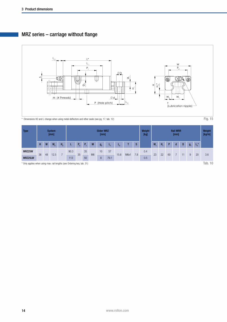
3 Product dimensions
MRZ series – carriage without flange
P1
L 1
L*
d
L 3P (Hole pitch)
g1
D
H1
L 2
S
M (4 Threads)
g2
P2
W
W1W2
H2*H
T(Lubrication nipple)
Fig. 15
Type System[mm]
Slider MRZ[mm]
Weight[kg]
Rail MRR[mm]
Weight[kg/m]
H W W2 H2 L P2 P1 M g2 L1 L2 T S W1 H1 P d D g1 L3*
MRZ25W36 48 12.5 7
90.335
35M6
10 5715.6 M6x1 7.8
0.423 22 60 7 11 9 20 3.6
MRZ25LW 113 50 8 79.1 0.5
Tab. 10
* Dimensions H2 and L change when using metal deflectors and other seals ( see pg. 17, tab. 12 )
* Only applies when using max. rail lengths ( see Ordering key, tab. 31 )
15www.rollon.com
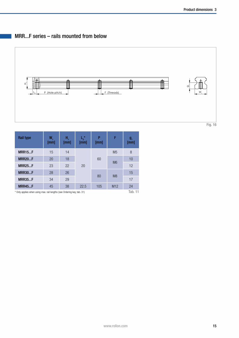
Product dimensions 3
MRR...F series – rails mounted from below
Rail type W1
[mm]H1
[mm]L3*
[mm]P
[mm]F g1
[mm]
MRR15...F 15 14
20
60
M5 8
MRR20...F 20 18M6
10
MRR25...F 23 22 12
MRR30...F 28 2680 M8
15
MRR35...F 34 29 17
MRR45...F 45 38 22.5 105 M12 24
Fig. 16
Tab. 11
H1
L3 P (Hole pitch) F (Threads) W1
g1
* Only applies when using max. rail lengths ( see Ordering key, tab. 31 )
16 www.rollon.com
4 Accessories
Fig. 17
Fig. 18
Fig. 19
Fig. 20
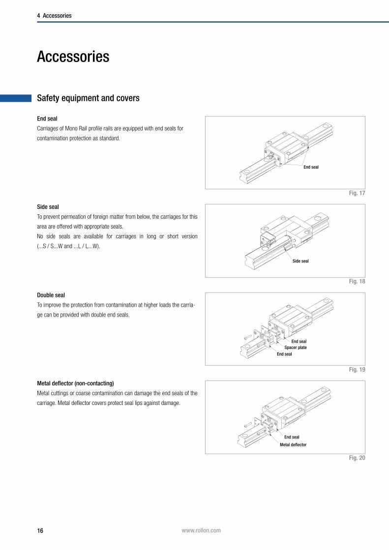
Accessories
Safety equipment and covers
End seal
Carriages of Mono Rail profile rails are equipped with end seals for
contamination protection as standard.
Side seal
To prevent permeation of foreign matter from below, the carriages for this
area are offered with appropriate seals.
No side seals are available for carriages in long or short version
(...S / S...W and ...L / L...W ).
Double seal
To improve the protection from contamination at higher loads the carria-
ge can be provided with double end seals.
Metal deflector (non-contacting)
Metal cuttings or coarse contamination can damage the end seals of the
carriage. Metal deflector covers protect seal lips against damage.
End seal
End sealSpacer plate
End seal
End seal
Metal deflector
Side seal

17www.rollon.com
Accessories 4
Seal variants:
A: Carriage with end and side seal
C: Carriage with end and side seals and metal deflector
D: Carriage with double end seal and side seal
E: Carriage with double end seal and side seal and metal deflector
Tab. 12
1 No side seals are available for carriages in long or short version (...S / S...W and ...L / L...W )
* For comparison see Chapter 3 Product dimensions, pg. 10ff
Changes of floor clearance and length changes of the carriages when
using the corresponding seal variants
Seal variant A, C, D, E, A C D E
Slider type1 Size Changed dimension H2*
[mm]
Changed lengthL*
[mm]
MRSMRS...WMRTMRT...W
15 2.5 73 75 79 83
20 2.9 85 87 91 95.2
25 4.9 94.7 97.7 101.4 106.6
30 6.9 117 119 127 131
35 7.6 118 120 128 132.6
45 12.05 146.7 148.7 157.4 161.9
MCSMCS...WMCTMCT...W
55 - - 192 191 200
MRS...L MRS...LW MRT...LW
20 - - 99.5 103.5 107.7
25 - - 117.7 121.4 126.6
30 - - 138.3 146.3 150.3
35 - - 143.6 151.6 156.2
45 - - 171.2 179.9 184.4
MCS...L MCS...LW MCT...LW
55 - - 234.2 233.2 242.2
MRT...S MRT...SW
15 - - 54.6 58.6 62.6
20 - - 64.1 68.1 72.3
25 - - 70.2 73.9 79.1
30 - - 83 91 95
35 - - 83.7 91.7 96.3
18 www.rollon.com
4 Accessories
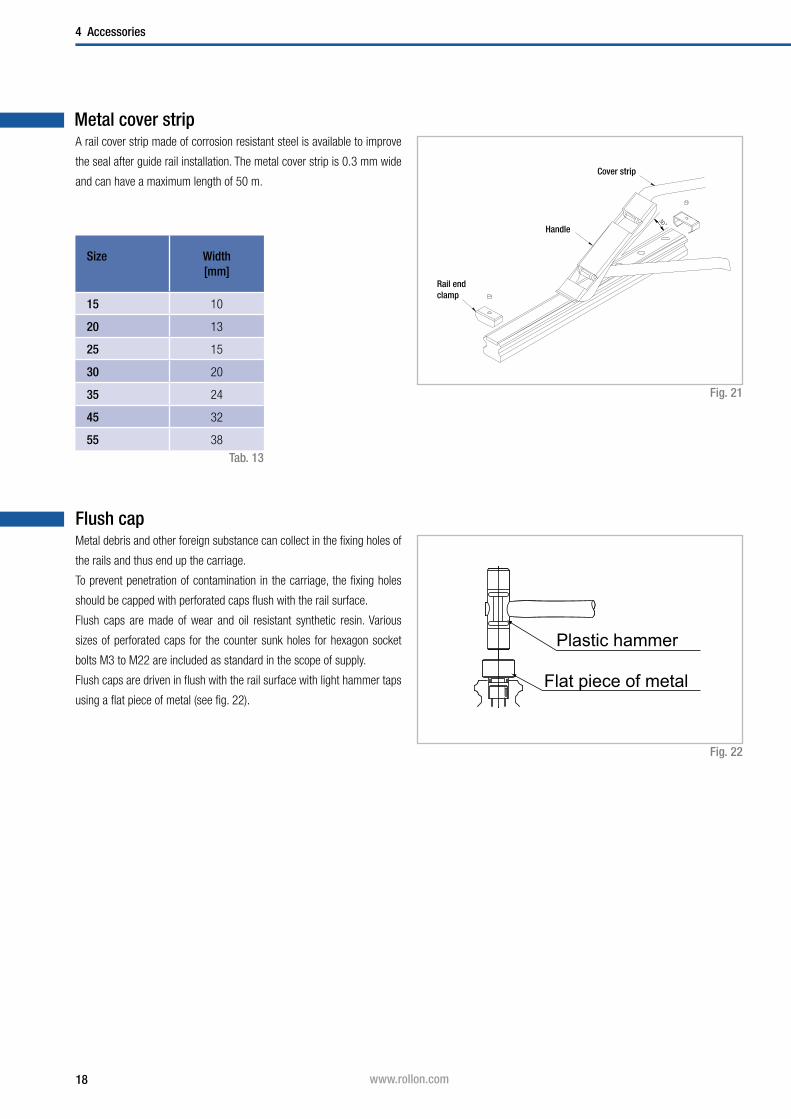
Metal cover strip
Fig. 21
Tab. 13
Size Width[mm]
15 10
20 13
25 15
30 20
35 24
45 32
55 38
Flush capMetal debris and other foreign substance can collect in the fixing holes of
the rails and thus end up the carriage.
To prevent penetration of contamination in the carriage, the fixing holes
should be capped with perforated caps flush with the rail surface.
Flush caps are made of wear and oil resistant synthetic resin. Various
sizes of perforated caps for the counter sunk holes for hexagon socket
bolts M3 to M22 are included as standard in the scope of supply.
Flush caps are driven in flush with the rail surface with light hammer taps
using a flat piece of metal (see fig. 22).
Fig. 22
30
A rail cover strip made of corrosion resistant steel is available to improve
the seal after guide rail installation. The metal cover strip is 0.3 mm wide
and can have a maximum length of 50 m.Cover strip
Handle
Rail end clamp
Plastic hammer
Flat piece of metal
19www.rollon.com
Accessories 4
Clamping elementsMono Rail profile rails can be secured with manual or pneumatic clamping
elements. Areas of application are:
■ Table cross beams and sliding beds
■ Width adjustment, stops
■ Positioning of optical equipment and measuring tables
Manual clamp elements HK
The HK series is a manually activated clamping element.
Contact profiles press synchronously on the free surfaces of the profile rail
by using the freely adjustable clamping lever.
The floating mounted contact profiles guarantee symmetrical introduction
of force on the guide rail.
Special characteristics of the clamping elements HK:
■ Simple and safe design
■ Floating contact profile
■ Precise positioning
■ Holding force up to 2,000 N
Variants:
An additional adapter plate must be used depending on the height of the
carriage ( see pg. 23, tab. 16 ).
Activation:
Standard with hand lever, further activation options, e.g. using DIN 912
screw, possible on request.
Pneumatic clamp elements MK / MKS
The patented wedge slide gear puts into effect high holding forces. The
pressurised medium moves the wedge slide gear in the longitudinal di-
rection.
Contact profiles press with high force on the free surfaces of the profile
rail by the resulting cross movement. MK is an element that closes with
pneumatic pressure. The custom design MKS closes with spring energy
storage and is opened via air impingement.
Special characteristics of clamp elements MK / MKS:
■ Short shape
■ High clamp forces
■ Precise positioning
■ High axial and horizontal rigidity
Areas of application of MK:
■ Positioning axes
■ Setting vertical axes
■ Positioning lifting gear
■ Clamping machine tables
Variants:
An additional adapter plate must be used depending on the height of the
carriage ( see pg. 23, tab. 17 ).
Connection options:
The basic MK / MKS series versions are equipped with air connections on
both sides, i.e. the factory default settings air connections and the ventila-
tion filter can be exchanged to the opposite side surfaces.
Custom design MKS opens with impingement of an air pressure of
> 5.5 bar.
Areas of application of MKS:
■ Clamping with drop in pressure (Normally Open)
■ Clamping without power required (Normally Closed)

20 www.rollon.com
4 Accessories
Fig. 23
Manual clamp HK
Tab. 14
W
HH
2
D*
g1
H1
H3
Adapter plate
P2
P 1L
W1
W2
M (4 Threads)
W
HH
2
D*
g1
H1
H3
Adapter plate
P2
P 1L
W1
W2
M (4 Threads)
* Changed dimensions when using the adapter plate, see pg. 22, tab. 16
Type Size Holding force
[N]
Tightening torque
[Nm]
Dimensions[mm]
M
H H1 H2 H3 W W1 W2 L P1 P2 g1
HK1501A 15
1200
5
24 12.5 6.5
44
47
30.5 33.5
25 17 17 5 M4
HK2006A20
2817.5
560 24 15 15 6 M5
HK2006A 30 7
HK2501A25 7
3615
1263 70 38.5 41.5 30 20 20
8 M6HK2514A 33 11.5
HK3001A 30
200015
4221.5
12
78
90
46.5 50.539
22 22
HK3501A 35 48 16 100 24 24 10 M8
HK4501A 45 60 26.5 18 120 44 26 26 14 M10
HK5501A 55 22 70 31 21 95 140 56.5 61.5 49 30 30 16 M14

21www.rollon.com
Accessories 4
Pneumatic clamp MK / MKS
Fig. 24
Tab. 15
* Changed dimensions when using the adapter plate, see pg. 22, tab. 17
W W1
H2
D*
H
W2B 4
g1
Adapter plate
LP 1
P 3
P2
L 1
Q
M (4 Threads)
W W1
H2
D*
H
W2
B 4
g1
Adapter plate
LP 1
P 3
P2
L 1
Q
M (4 Threads)
* Only for model MKS
Type Size MK holding force
[N]
MKS holding force
[N]
Dimensions[mm]
M
H H2 W W1 W2 B4 L1* L P1 P2 P3 Q[∅]
g1
MK / MKS1501A 15 650 400 24
2.5
55
6
34 12 58
39
15 15 15.5 16 4.5 M4
MK / MKS 2001A 20 1000 600 28 66 43 14.4 61
20 20 5
20 5 M5
MK / MKS 2501A 25 1200 750 36 8 75
5
49 15.5 56 35 22 8 M6
MK / MKS 3001A 30 1750 1050 42 7 90 58
20.5
68
39
22 22 8.5 25
10 M8MK / MKS 3501A 35 2000 1250 48 11.5 100 68 67 24 24 7.5 28
MK / MKS 4501A 45
2250 1450
60 16.5 120 78.8 26.8
82 49
26 26 11.5
30
15
M10MK / MKS 5501A 55 70 21.5 128 87 30.5 30 30 9.5 18

22 www.rollon.com
4 Accessories
Adapter plate
For HK clamps
Clamp Size Slider type Adapter plate D
HK1501A 15MRS, MRT...W, MRT...SW - 24
MRS...W PHK 15-4 28
HK2006A 20MRT...S, MRT...W, MRT...SW - 28
MRS, MRS...L, MRS...W, MRS...LW - 30
HK2514A
25
MRT, MRT...S, MRT...W, MRT...SW, MRT...LW - 33
HK2501AMRS, MRS...L, - 36
MRS...W, MRS...LW PHK 25-4 40
HK3001A 30MRS, MRS...L, MRT...W, MRT...SW, MRT...LW - 42
MRS...W, MRS...LW PHK 30-3 45
HK3501A 35MRS, MRS...L, MRT...W, MRT...SW, MRT...LW - 48
MRS...W, MRS...LW PMK 35-7 55
HK4501A 45MRS, MRS...L, MRT...W, MRT...LW - 60
MRS...W, MRS...LW PHK 45-10 70
On request
55
MRT...W, MRT...LW - 68
HK5501AMRS, MRS...L - 70
MRS...W, MRS...LW PHK 55-10 80
Tab. 16
For MK / MKS clamps
Clamp Size Slider type Adapter plate D
MK / MKS1501A
15MRS, MRT...W, MRT...SW - 24
MRS...W PMK 15-4 28
MK / MKS 2001A
20MRT...S, MRT...W, MRT...SW - 28
MRS, MRS...L, MRS...W, MRS...LW PMK 20-2 30
On request
25
MRT, MRT...S, MRT...W, MRT...SW, MRT...LW - 33
MK / MKS 2501A
MRS, MRS...L, MRZ - 36
MRS...W, MRS...LW PMK 25-4 40
MK / MKS 3001A
30MRS, MRS...L, MRT...W, MRT...SW, MRT...LW - 42
MRS...W, MRS...LW PMK 30-3 45
MK / MKS 3501A
35MRS, MRS...L, MRT...W, MRT...SW, MRT...LW - 48
MRS...W, MRS...LW PMK 35-7 55
MK / MKS 4501A
45MRS, MRS...L, MRT...W, MRT...LW - 60
MRS...W, MRS...LW PMK 45-10 70
On request
55
MRT...W, MRT...LW - 68
MK / MKS 5501A
MRS, MRS...L - 70
MRS...W, MRS...LW PMK 55-10 80
Tab. 17

23www.rollon.com
Technical instructions 5
Fig. 26
H
WA B
CD
W
HA B
CD
Technical instructions
PrecisionPrecision means the guide accuracy or the maximal deviation of the car-
riage based on the side and support surfaces during the movement along
the rails.
Fig. 25
Precision class[mm]
Normal[N]
High[H]
Precise[P]
Height tolerance H± 0.1 ± 0.04 0 to -0.04
Side tolerance W
Guide accuracy of raceway C based on surface A
∆C see graph in fig. 26
Guide accuracy of raceway D based on surface B
∆D see graph in fig. 26
Tab. 18
C D
A W B
H
C D
A WB
H
Schienenlänge (mm)
C (μm)
D (μm)
Normal ( N)
Hoch ( H )
Präzise ( P )
Abb. 1
(*) beim Einsatz mehrerer Läufer / Schienen
Normal (N)
High (H)
Precise (P)
Rail length (mm)
∆ C (µm)
∆ D (µm)

24 www.rollon.com
5 Technical instructions
Radial clearance / preload
The radial clearance for the respective preload classes are listed in
table 20.
Degree of preload Preload class Preload
With clearance G1 0
No clearance K0 0
Small preload K1 0,02 x C*
Average preload K2 0,05 x C*
Tab. 19* C is the dynamic load capacity, see pg. 9, tab. 1f
Radial clearance describes the value for the radial movement of the car-
riage at a constant vertical load, while the carriage moves in longitudinal
direction.
Fig. 27
Preload is defined as an effective load on the rolling element in the interior
of the carriage in order to remove an existing clearance or to increase
the rigidity.
The Mono Rail profile rails are available in the four different preload
classes G1, K0, K1 and K2 ( see tab. 19 ). The preload influences the rigi-
dity, precision and torque resistance and also affects the service life and
displacement force.
Size Radial clearance of the preload classes[µm]
G1
Impact free mo-vement, compen-sation of assembly
tolerances
K0
Impact free and easy movement
K1
Small moments, one rail application, low
vibrations
K2
Average vibrations and moments, light
impacts
15 +4 to +14 -4 to +4 -12 to -4 -20 to -12
20 +5 to +15 -5 to +5 -14 to -5 -23 to -14
25 +6 to +16 -6 to +6 -16 to -6 -26 to -16
30 +7 to +17 -7 to +7 -19 to -7 -31 to -19
35 +8 to +18 -8 to +8 -22 to -8 -35 to -22
45 +10 to +20 -10 to +10 -25 to -10 -40 to -25
55 +12 to +22 -12 to +12 -29 to -12 -46 to -29
Tab. 20

25www.rollon.com
Technical instructions 5
LubricationProfile rails must generally be lubricated before commissioning. They can
be lubricated with oil or grease.
The correct lubricant selection has a large influence on the service life and
the function of the profile rail, insufficient lubrication and tribocorrosion
can ultimately lead to total failure.
Important instructions for lubrication
■ Mono Rail profile rails must be lubricated for operation.
■ The carriage must be moved back and forth during lubrication.
■ The lubricant is inserted through a lubrication nipple.
■ There should be a thin film of lubricant on the rail surface at all times.
■ Please inform us in advance if the guides are to be used in acid or base
containing environments or in clean rooms.
Grease lubrication
We recommend the use of a lithium emulsified lubricant NLGI Class 2 for
lubrication.
Oil lubrication
We recommend a synthetic oil for operating temperatures between 0 °C
and +70 °C. For application-specific custom lubrication, please contact
Application Technology.
Relubrication
■ Relubrication of the system must be done before the lubricant used is
dirty or shows discolouration.
■ Relubrication is performed at operating temperature. The carriage
must be moved back and forth during relubrication.
■ If the stroke is < 2 or > 15 times the carriage length, the lubrication
intervals should be more often.
Lubrication intervals
Operating speed, stroke length and ambient conditions influence the
selection of time between lubrication intervals. Establishing a safe lubri-
cation interval is based exclusively on the experienced practiced values
determined on site. However, a lubrication interval should not be longer
than one year in any case.
■ Primary lubricated systems have an increased displacement resi-
stance.
■ Please contact Application Technology if the oil lubrication is used for
vertical use.
■ If the stroke is < 2 or > 15 times the carriage length, the lubrication
intervals should be shortened.
Anticorrosive protectionThere are numerous application-specific surface treatments available for
profile rails of the Mono Rail product family, for example, black coating ( X ),
hard chrome plating ( XC ) or nickel plating ( NIC ), also with FDA-approval
for use in the food industry. For more information please contact Applica-
tion Technology.
As well as reducing friction and wear, lubricants also serve as sealant,
noise damper and corrosion protection for the linear guide. Different lubri-
cants for special applications are available upon request.
Example: Lubricant with FDA approval for use in the food industry.
For more information please contact Application Technology.
26 www.rollon.com
5 Technical instructions
Size Initial lubrication grease
[cm3]
Relubrication
[cm3]
Initial lubrication oil
[cm3]
15 1.3 1.1 1.5
20 2.3 2 2.5
25 2.8 2.5 3.5
30 3.5 3 4.5
55 5.5 4 5.5
Size Initial lubrication grease
[cm3]
Relubrication
[cm3]
Initial lubrication oil
[cm3]
35 3.5 3 3.5
45 4.5 3.5 4.5
Tab. 22
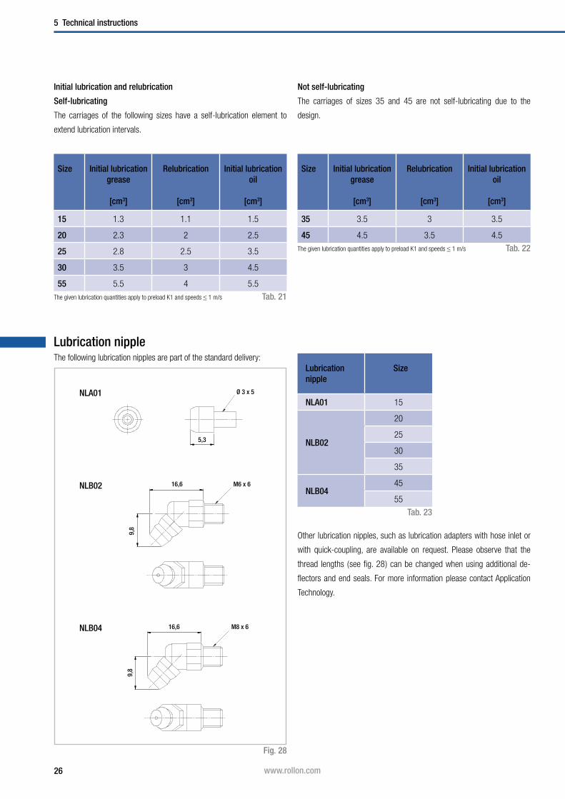
Lubrication nipple
NLB02
NLB04
Fig. 28
Tab. 23
The following lubrication nipples are part of the standard delivery:
Other lubrication nipples, such as lubrication adapters with hose inlet or
with quick-coupling, are available on request. Please observe that the
thread lengths ( see fig. 28 ) can be changed when using additional de-
flectors and end seals. For more information please contact Application
Technology.
NLA01
Lubrication nipple
Size
NLA01 15
NLB02
20
25
30
35
NLB0445
55
Tab. 21
Self-lubricating
Not self-lubricatingInitial lubrication and relubrication
The carriages of the following sizes have a self-lubrication element to
extend lubrication intervals.
The carriages of sizes 35 and 45 are not self-lubricating due to the
design.
Ø 3 x 5
5,3
16,6
9,8
M6 x 6
16,6
9,8
M8 x 6
The given lubrication quantities apply to preload K1 and speeds ≤ 1 m/s
The given lubrication quantities apply to preload K1 and speeds ≤ 1 m/s

27www.rollon.com
Technical instructions 5
Friction / displacement resistanceMono Rail profile rails have a low friction characteristic and thus low dis-
placement resistance. The low start-up friction (breakaway force) is al-
most identical to the moving friction (running resistance).
The displacement resistance is dependent upon several factors:
■ Friction of the sealing system
■ Friction of the balls with each other
■ Friction between balls and redirection
■ Rolling resistance of the balls in the running grooves
■ Resistance of lubricant in the carriage
■ Resistance by contamination in the lubricant
■ Preload for increase of rigidity
■ Moment load
Mono Rail profile rails have a coefficient of friction of approx.
µ = 0.002 - 0.003.
Fm = µ · F + f
Fm = Displacement resistance ( N )
F = Load ( N )
µ = Coefficient of friction
f = Resistance of the seals ( N )
Fig. 30
Tab. 24
Type f[N]
MRS15 0.15
MRS20 0.2
MRS25 0.35
MRS30 0.7
MRS35 0.8
MRS45 0.9
MCS55 1.0
Resistance of the seals
Fig. 29
Displacement resistance
The following formula is used for general approximate calculation of the
displacement resistance. Please note that the level of preload or the visco-
sity of the lubricant used can also influence the displacement resistance.
Coef
ficie
nt o
f fric
tion
(µ)
Loading ratio: (P/C)P: LoadingC: Dynamic load capacities
0.005
0.010
0.015
2.01.00

28 www.rollon.com
5 Technical instructions
Loading
Fig. 31
Operating conditions S0
Normal operation 1 ~ 2
Loading with vibration or shock effect 2 ~ 3
Loading with strong vibration or impacts ≥ 3
Tab. 25
The safety factor S0 can lie on the lower given limit if the occurring forces
can be determined with sufficient precision. If shock and vibration are
present, the higher value should be selected. For dynamic applications
higher safety is required. Please contact the Application Engineering De-
partment.
Safety factor
The given static load capacity for each carriage represents the maximum
permissible load value, which if exceeded causes permanent deforma-
tions of the raceways and adverse effects of the running properties.
Checking the load must be done as follows:
- through determination of the simultaneously occurring forces and
moments for each carriage
- by comparison of these values with the corresponding load capacities.
The ratio of the actual load to maximum permissible load may be as large
as the reciprocal of the accepted safety factor, S0, at the most.
Fig. 32
The above formulas are valid for a single load case.
If two or more forces are acting simultaneously, please check the following
formula:
P0rad 1
C0rad
S0
≤P
0ax 1
C0ax
S0
≤M
1 1
Mx S
0
≤M
2 1
My S
0
≤M
3 1
Mz S
0
≤
P0rad
= effective radial load (N)
C0rad
= permissible radial load (N)
P0ax
= effective axial load (N)
C0ax
= permissible axial load (N)
M1, M
2, M
3 = external moments ( Nm)
Mx, M
y, M
z = maximum permissible moments
in the different loading directions (Nm)
P0rad
P0ax
M1 M
2 M
3
C0rad
C0ax
Mx M
y M
z
+ + + + ≤1
S0

29www.rollon.com
Technical instructions 5
Service life
The dynamic load capacity C is a conventional variable used for calcula-
ting the service life. This load corresponds to a nominal service life of 50
km. The relationship between calculated service life Lkm
( in km ), dynamic
load capacity C ( in N ) and equivalent load P ( in N ) is given in the formula
to the right:Fig. 33
fc = contact factor
fi = application coefficient
Calculation of service life:
The contact factor fc refers to applications in which several carriages pass
the same rail section. If two or more carriages are moved over the same
point on a rail, the static and dynamic loading values must be multiplied
with the numbers from the table below:
Contact factor fc
Number of carriages
1 2 3 4 5
fc 1 0.81 0.72 0.66 0.61
Tab. 26
The application coefficient fi can be understood as the dynamic safety
factor. Refer to the table below for the values:
Application coefficient fi
Operational conditions Speed fi
Neither external impacts nor vibrations Low speed V ≤ 15 m/min. 1 - 1.5
Light impacts or vibrations Average speed 15 < V ≤ 60 m/min. 1.5 - 2
Average and high external impacts or vibrations High speed V > 60 m/min. 2 - 3.5
Tab. 27
The equivalent load P corresponds in its effects to the sum of the forces
and moments working simultaneously on a slider. If these different load
components are known, P results from the equation to the right:
Fig. 34
Lkm
= ( · )3 · 50 km C
P
fc
fi
P = | P0ax
| + | P0rad
| + ( + + ) · C0rad
| M1|
Mx
| M2|
My
| M3|
Mz
30 www.rollon.com
5 Technical instructions
SmSm
Lv
Hc
Ground stop surfaceSm
Sm
Lv
Hr
Ground surface
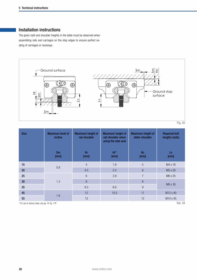
Installation instructions
Fig. 35
Size Maximum level of incline
Sm[mm]
Maximum height of rail shoulder
Hr[mm]
Maximum height of rail shoulder when using the side seal
Hr*[mm]
Maximum height of slider shoulder
Hc[mm]
Required bolt lengths (rails)
Lv [mm]
150.8
4 1.9 5 M4 x 16
20 4.5 2.4 6 M5 x 20
25
1.2
6 3.9 7 M6 x 25
30 8 - 8M8 x 30
35 8.5 6.6 9
451.6
12 10.5 11 M12 x 40
55 13 - 12 M14 x 45
Tab. 28
The given radii and shoulder heights in the table must be observed when
assembling rails and carriages on the stop edges to ensure perfect se-
ating of carriages or raceways.
* For use of various seals, see pg. 16, fig. 17ff
31www.rollon.com
Technical instructions 5
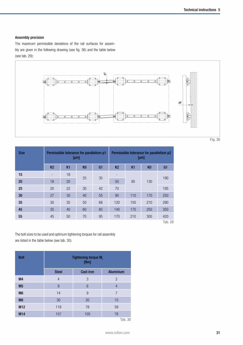
The bolt sizes to be used and optimum tightening torques for rail assembly
are listed in the table below ( see tab. 30 ).
The maximum permissible deviations of the rail surfaces for assem-
bly are given in the following drawing ( see fig. 36 ) and the table below
( see tab. 29 ):
Assembly precision
Fig. 36
Size Permissible tolerance for parallelism p1 [µm]
Permissible tolerance for parallelism p2 [µm]
K2 K1 K0 G1 K2 K1 K0 G1
15 - 1825 35
-
85 130190
20 18 20 50
25 20 22 30 42 70 195
30 27 30 40 55 90 110 170 250
35 30 35 50 68 120 150 210 290
45 35 40 60 85 140 170 250 350
55 45 50 70 95 170 210 300 420
Tab. 29
Bolt Tightening torque Mt
[Nm]
Steel Cast iron Aluminium
M4 4 3 2
M5 9 6 4
M6 14 9 7
M8 30 20 15
M12 118 78 59
M14 157 105 78
p1p2
Tab. 30

32 www.rollon.com
5 Technical instructions
A A
A1 A1 A2 A2
B1 B1 B2 B2
Guide rails longer than the one part maximum length ( see Ordering key,
tab. 31), are put together from two or more rails.
When putting guide rails together, be sure that the register marks shown
in fig. 37 are positioning correctly.
These are fabricated axisymmetric for parallel application of composite
guide rails, unless otherwise specified.
Composite rails
Fig. 37
Two rails
Several rails
Comp. L
Comp. L
Joint
Joint marks
Joint marks
Joint marks
Joint marks
Joint marks
Joint
Joint
Joint
Joint
33www.rollon.com
Technical instructions 5
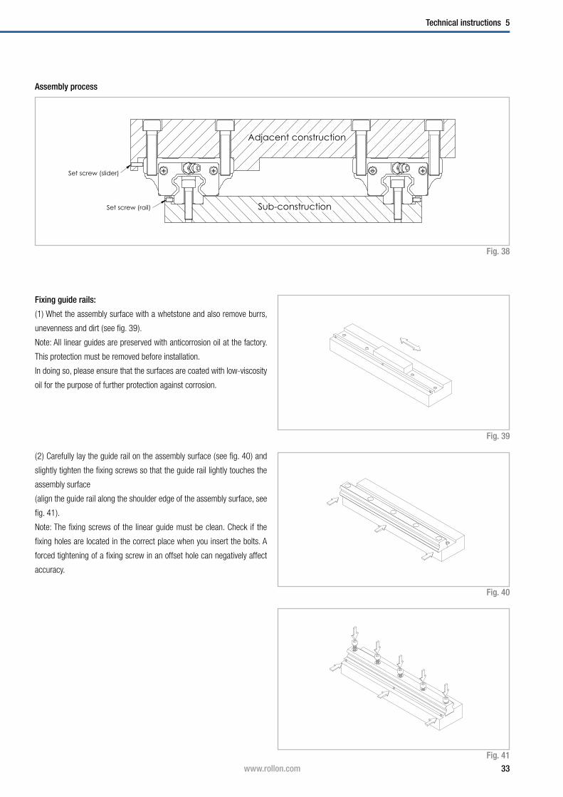
Adjacent construction
Sub-constructionSet screw (rail)
Set screw (slider)
Fixing guide rails:
( 1) Whet the assembly surface with a whetstone and also remove burrs,
unevenness and dirt ( see fig. 39 ).
Note: All linear guides are preserved with anticorrosion oil at the factory.
This protection must be removed before installation.
In doing so, please ensure that the surfaces are coated with low-viscosity
oil for the purpose of further protection against corrosion.
( 2 ) Carefully lay the guide rail on the assembly surface ( see fig. 40 ) and
slightly tighten the fixing screws so that the guide rail lightly touches the
assembly surface
( align the guide rail along the shoulder edge of the assembly surface, see
fig. 41 ).
Note: The fixing screws of the linear guide must be clean. Check if the
fixing holes are located in the correct place when you insert the bolts. A
forced tightening of a fixing screw in an offset hole can negatively affect
accuracy.
Assembly process
Fig. 38
Fig. 41
Fig. 40
Fig. 39
34 www.rollon.com
5 Technical instructions
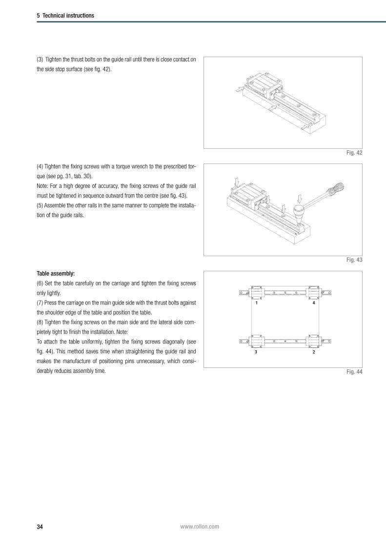
( 3 ) Tighten the thrust bolts on the guide rail until there is close contact on
the side stop surface ( see fig. 42 ).
( 4 ) Tighten the fixing screws with a torque wrench to the prescribed tor-
que ( see pg. 31, tab. 30 ).
Note: For a high degree of accuracy, the fixing screws of the guide rail
must be tightened in sequence outward from the centre ( see fig. 43 ).
( 5 ) Assemble the other rails in the same manner to complete the installa-
tion of the guide rails.
Table assembly:
( 6 ) Set the table carefully on the carriage and tighten the fixing screws
only lightly.
( 7 ) Press the carriage on the main guide side with the thrust bolts against
the shoulder edge of the table and position the table.
( 8 ) Tighten the fixing screws on the main side and the lateral side com-
pletely tight to finish the installation. Note:
To attach the table uniformly, tighten the fixing screws diagonally ( see
fig. 44 ). This method saves time when straightening the guide rail and
makes the manufacture of positioning pins unnecessary, which consi-
derably reduces assembly time. Fig. 44
Fig. 42
1
2
4
3
Fig. 43
35www.rollon.com
Technical instructions 5
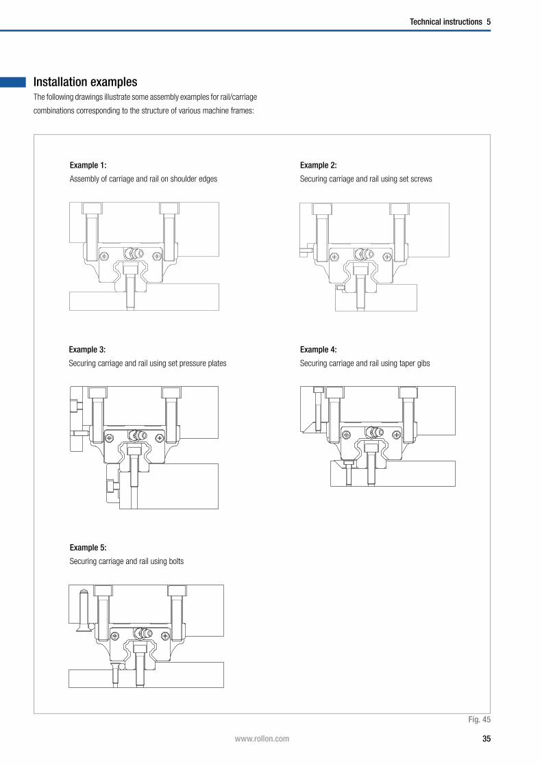
Installation examplesThe following drawings illustrate some assembly examples for rail/carriage
combinations corresponding to the structure of various machine frames:
Example 1:
Assembly of carriage and rail on shoulder edges
Example 3:
Securing carriage and rail using set pressure plates
Example 5:
Securing carriage and rail using bolts
Example 2:
Securing carriage and rail using set screws
Example 4:
Securing carriage and rail using taper gibs
Fig. 45
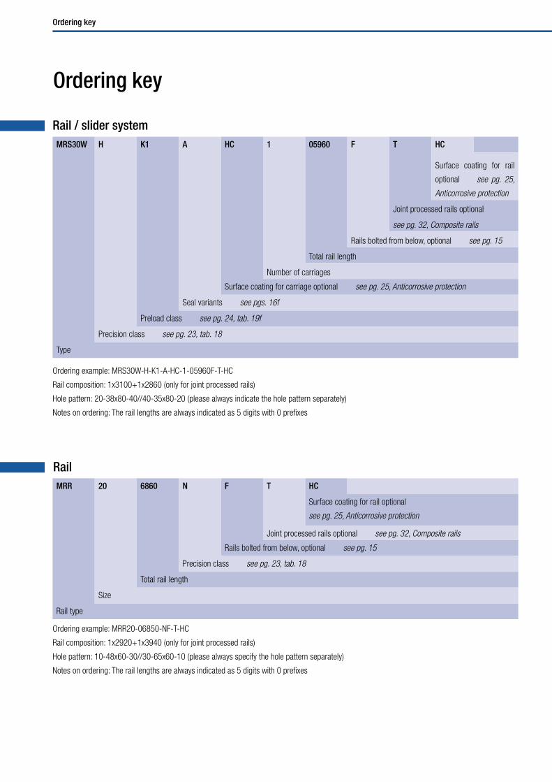
Ordering key
Ordering key
MRR 20 6860 N F T HC
Surface coating for rail optional
see pg. 25, Anticorrosive protection
Joint processed rails optional see pg. 32, Composite rails
Rails bolted from below, optional see pg. 15
Precision class see pg. 23, tab. 18
Total rail length
Size
Rail type
Rail
Rail / slider system
Ordering example: MRR20-06850-NF-T-HC
Rail composition: 1x2920+1x3940 (only for joint processed rails)
Hole pattern: 10-48x60-30//30-65x60-10 (please always specify the hole pattern separately)
Notes on ordering: The rail lengths are always indicated as 5 digits with 0 prefixes
Ordering example: MRS30W-H-K1-A-HC-1-05960F-T-HC
Rail composition: 1x3100+1x2860 (only for joint processed rails)
Hole pattern: 20-38x80-40//40-35x80-20 (please always indicate the hole pattern separately)
Notes on ordering: The rail lengths are always indicated as 5 digits with 0 prefixes
MRS30W H K1 A HC 1 05960 F T HC
Surface coating for rail
optional see pg. 25,
Anticorrosive protection
Joint processed rails optional
see pg. 32, Composite rails
Rails bolted from below, optional see pg. 15
Total rail length
Number of carriages
Surface coating for carriage optional see pg. 25, Anticorrosive protection
Seal variants see pgs. 16f
Preload class see pg. 24, tab. 19f
Precision class see pg. 23, tab. 18
Type

Ordering key
Carriage
Ordering example: MRS35-N-K0-A-HC
MRS35 N K0 A HC
Surface coating for carriage optional see pg. 25, Anticorrosive protection
Seal variants see pgs. 16f
Preload class see pg. 24, tab. 19f
Precision class see pg. 23, tab. 18
Type
Size Hole pitch P[mm]
L2min, L3min
[mm]L2max*, L3max*
[mm]L0max
[mm]
15
60 7
20
400020
25
3080 8.5 3960
35
45 105 11.5 22.5 3930
55 120 13 30 3900
Fig. 46
Tab. 31
Rail
Hole pattern
L0
L2 0,5 mm+– P L3 0,5 mm+–
* Only applies when using max. rail lengths

Portfolio
Portfolio
COMPACT RAIL
Rugged roller sliders with innovative
self adjustment
UNILINE
Steel-reinforced, belt-driven linear actuators
with hardened steel linear bearings
and precision radial ball bearing rollers
MINIATURE MONO RAIL
Miniature format profile guideways
with unique ball design
TELESCOPIC RAIL
Smooth-running telescopic linear
bearing drawer slides with
low deflection under heavy loads
LIGHT RAIL
Full and partial extension, lightweight
drawer slides
CURVILINE
Curvilinear rails for constant
and variable radii
EASY RAIL
Compact, versatile linear bearings
X-RAIL
Roller embossed stainless steel profiles
for the use in rough environments

Fold out ordering key
Fold out ordering key
To make this product catalog as simple as possible for you to use, we have
included the following easy-to-read chart.
Your advantages:
■ Description and ordering designations easy to read at one glance
■ Simplified selection of the correct product
■ Links to detailed descriptions in the catalog
Italy
Germ
any
ROLLON GmbH
Bonner Strasse 317-319
D-40589 Düsseldorf
Tel.: (+49) 211 95 747 0
Fax: (+49) 211 95 747 100
E-Mail: [email protected]
www.rollon.de
RL_MR_EN_02/13
ROLLON S.r.l.
Via Trieste 26
I-20871 Vimercate (MB)
Tel.: (+39) 039 62 59 1
Fax: (+39) 039 62 59 205
E-Mail: [email protected]
www.rollon.itNe
therland
s
ROLLON B.V.
Ringbaan Zuid 8
6905 DB Zevenaar
Tel.: (+31) 316 581 999
Fax: (+31) 316 341 236
E-Mail: [email protected]
www.rollon.nl
France
ROLLON S.A.R.L.
Les Jardins d‘Eole, 2 allée des Séquoias
F-69760 Limonest
Tel.: (+33) (0)4 74 71 93 30
Fax: (+33) (0)4 74 71 95 31
E-Mail: [email protected]
www.rollon.fr USA
ROLLON Corporation
101 Bilby Road. Suite B
Hackettstown, NJ 07840
Tel.: (+1) 973 300 5492
Fax: (+1) 908 852 2714
E-Mail: [email protected]
www.rolloncorp.com
All addresses of our global sales partners can also
be found in the internet at www.rollon.com
Changes and errors excepted. The text and images may be used only with our permission.