robin stevens - queensland rail - turnout design and components
DESCRIPTION
Robin Stevens delivered the presentation at 2014 RISSB National Rail Turnouts Workshop. The RISSB National Rail Turnouts Workshop gives all those involved an in-depth forum for discussion and the sharing of expertise. A key element of this workshop is participation and knowledge sharing from audience as well as the workshop leaders. It is a chance for you to bring your experience and to take away new approaches for best practice. For more information about the event, please visit: http://www.informa.com.au/railturnoutsworkshop14TRANSCRIPT
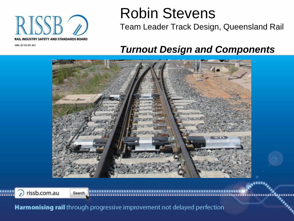
Robin StevensTeam Leader Track Design, Queensland Rail
Turnout Design and Components
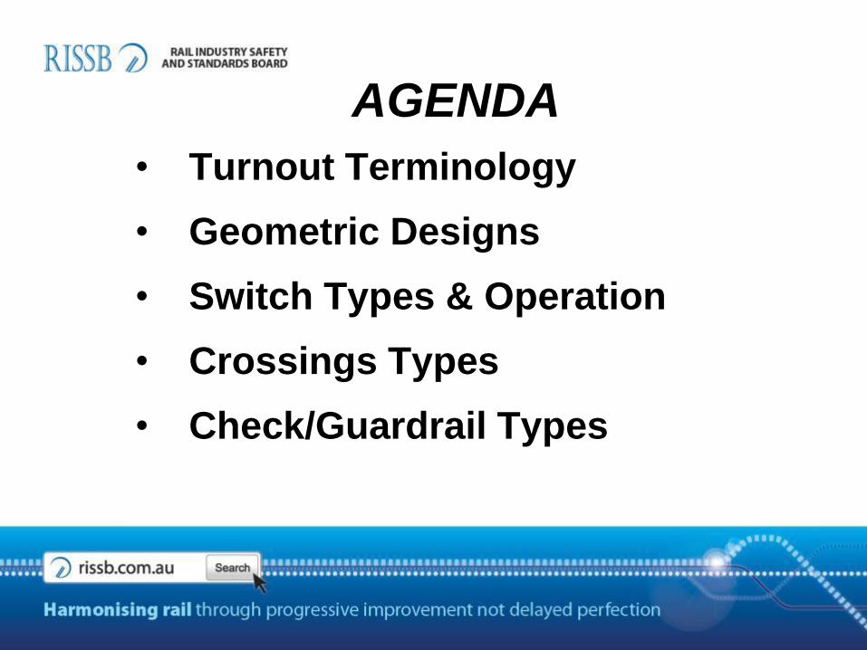
AGENDA
• Turnout Terminology
• Geometric Designs
• Switch Types & Operation
• Crossings Types
• Check/Guardrail Types
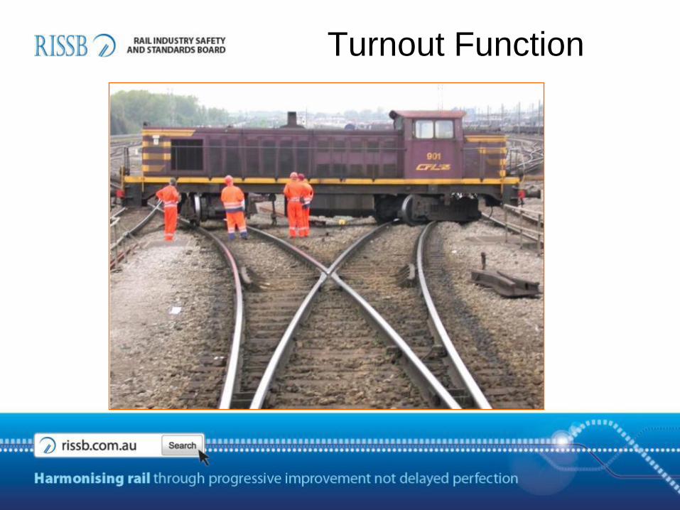
Turnout Function
TurnoutPoints Assembly
Crossing Assembly
Guard Rails
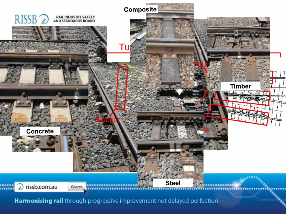
Sleeper
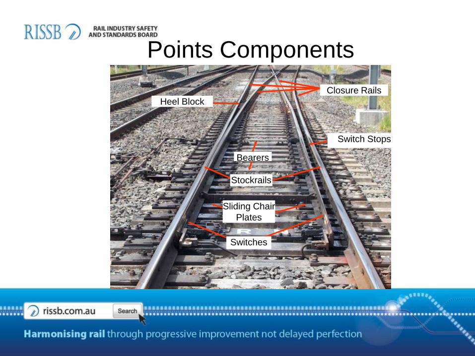
Switches
Sliding Chair
Plates
Switch Stops
Stockrails
Points Components
Heel Block
Bearers
Closure Rails
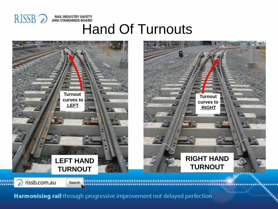
Hand Of Turnouts
LEFT HAND
TURNOUT
RIGHT HAND
TURNOUT
Turnout
curves to
LEFT
Turnout
curves to
RIGHT
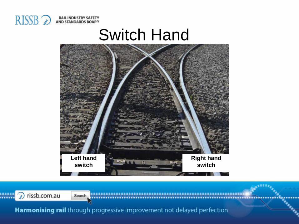
Switch Hand
Right hand
switch
Left hand
switch

• Turnouts are manufactured in :
68kg, 60kg, 53kg, 50kg, 47kg, 41kg, 31kg & 22kg Rail
• Queensland Rail standard Turnout range of angles includes:
60kg – 1 in 8.25, 9, 10, 12, 16 & 25
53kg – 1 in 8.25, 9, 10, 10.5 & 12
50kg – 1 in 8 & 12
47kg – 1 in 7, 7.5, 8, 9, 10, 11, 12, 13, & 14
41kg – 1 in 5 ,5.5, 6, 6.5, 7, 7.5, 8, 9, 10, 11, 12, 13 & 14
31kg – 1 in 5 ,5.5, 6, 6.5, 7, 7.5, 8, 9, 10, 11, 12, 13 & 14
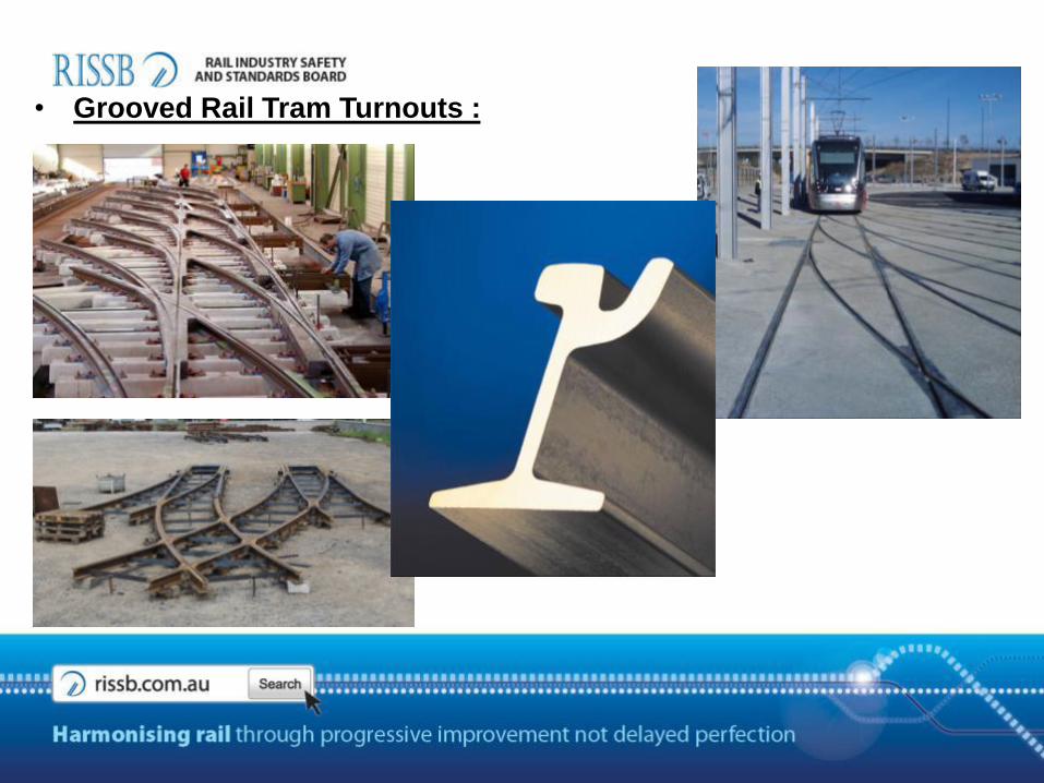
• Grooved Rail Tram Turnouts :
GEOMETRIC DESIGNS
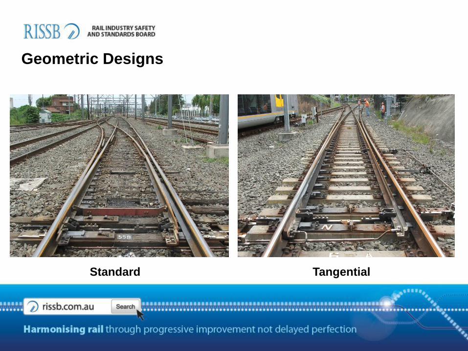
Geometric Designs
Standard Tangential
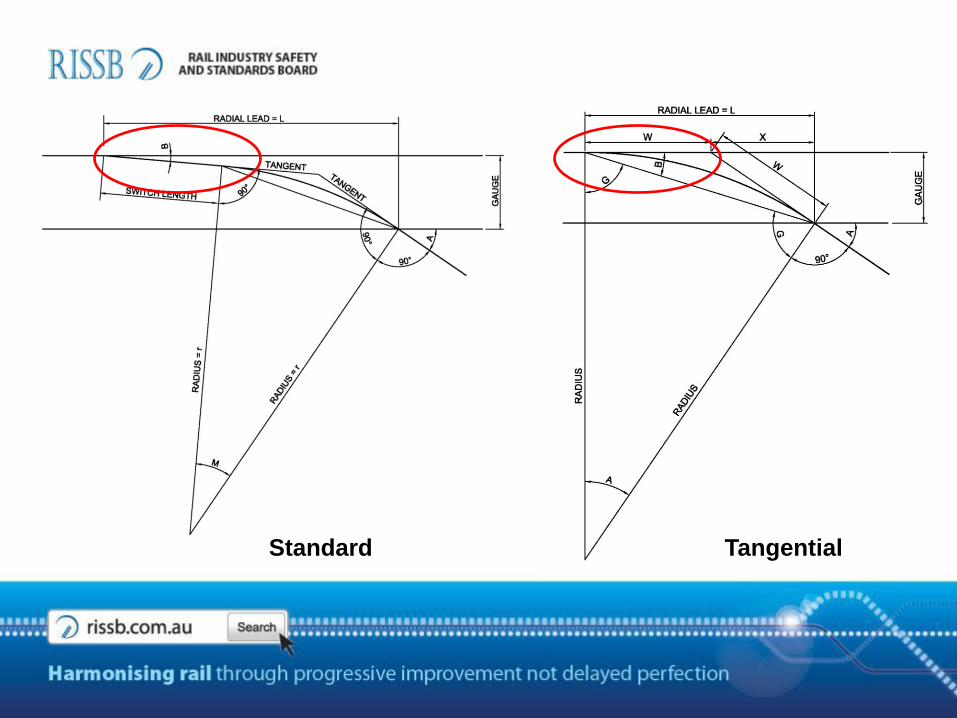
Standard Tangential
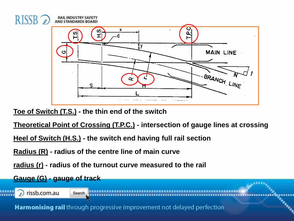
Toe of Switch (T.S.) - the thin end of the switch
Theoretical Point of Crossing (T.P.C.) - intersection of gauge lines at crossing
Heel of Switch (H.S.) - the switch end having full rail section
Radius (R) - radius of the centre line of main curve
radius (r) - radius of the turnout curve measured to the rail
Gauge (G) - gauge of track

Crossing Rate - rate of crossing, expressed as the side of a right angled triangle
Crossing Angle (A) - angle of crossing in degrees
Switch Angle (B) - angle between the switch gauge line and stock rail gauge line
Heel Centres (d) - the distance between gauge lines at the heel of the switch
Switch Length (S) - the length of the switch from heel to toe
Lead (L) - distance from toe of switch to T.P.C
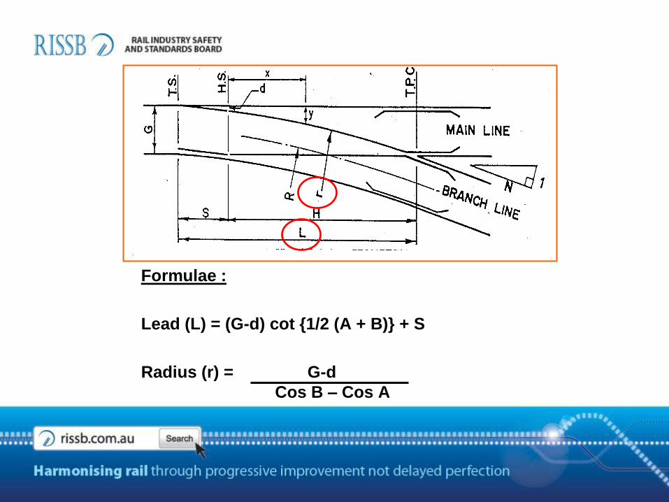
Formulae :
Lead (L) = (G-d) cot {1/2 (A + B)} + S
Radius (r) = G-d
Cos B – Cos A

• Switch Length (S) = 5000 mm
• Crossing Rate (N) = 1 in 10
• Heel Centres (d) = 160 mm
• Thickness of Tip = 3 mm
1 IN 10 SIMPLE TURNOUT
3
• Gauge (G) = 1067 mm
• Crossing angle (A) = tan-1 1/N
= tan-1 1/10
= 5.710 deg
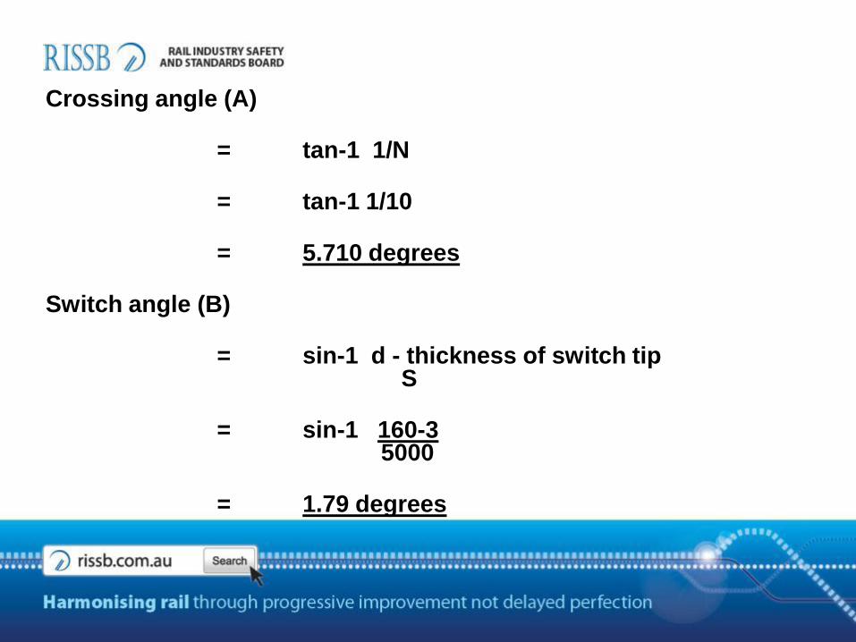
Crossing angle (A)
= tan-1 1/N
= tan-1 1/10
= 5.710 degrees
Switch angle (B)
= sin-1 d - thickness of switch tipS
= sin-1 160-35000
= 1.79 degrees
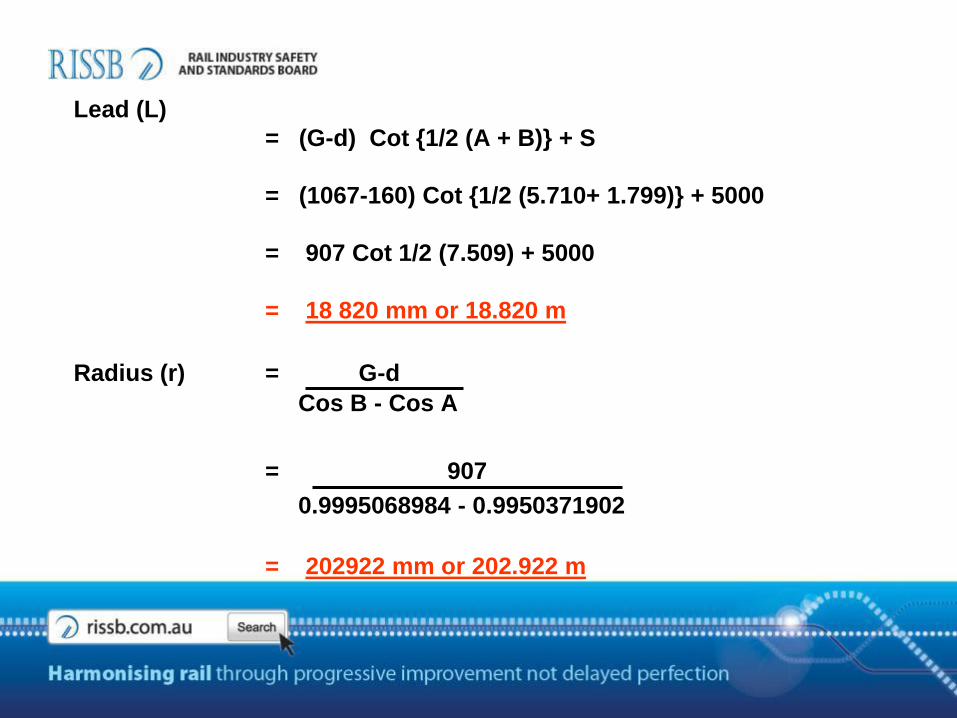
Lead (L)
= (G-d) Cot {1/2 (A + B)} + S
= (1067-160) Cot {1/2 (5.710+ 1.799)} + 5000
= 907 Cot 1/2 (7.509) + 5000
= 18 820 mm or 18.820 m
Radius (r) = G-d
Cos B - Cos A
= 907
0.9995068984 - 0.9950371902
= 202922 mm or 202.922 m
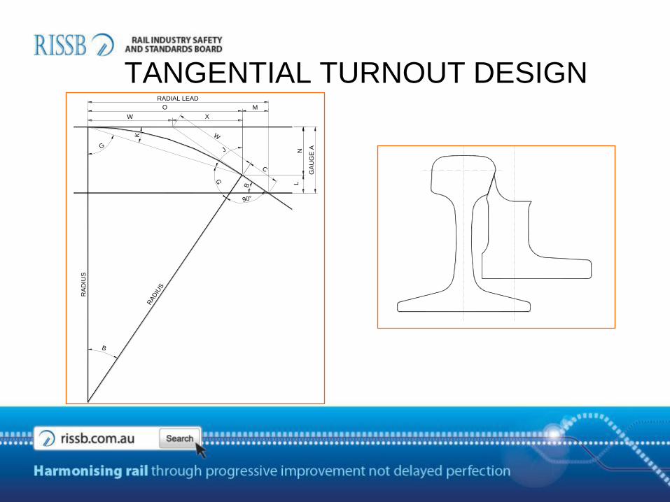
TANGENTIAL TURNOUT DESIGN
LN
RAD
IUS
RA
DIU
S
WK
GJ
G
90°
B
RADIAL LEAD
X
O
W
GA
UG
E A
M
B
C
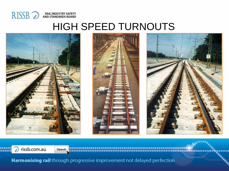
HIGH SPEED TURNOUTS
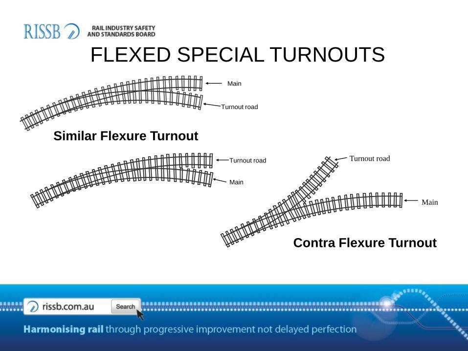
Contra Flexure Turnout
Similar Flexure Turnout
Main
Turnout road
Main
Turnout road
Main
Turnout road
FLEXED SPECIAL TURNOUTS
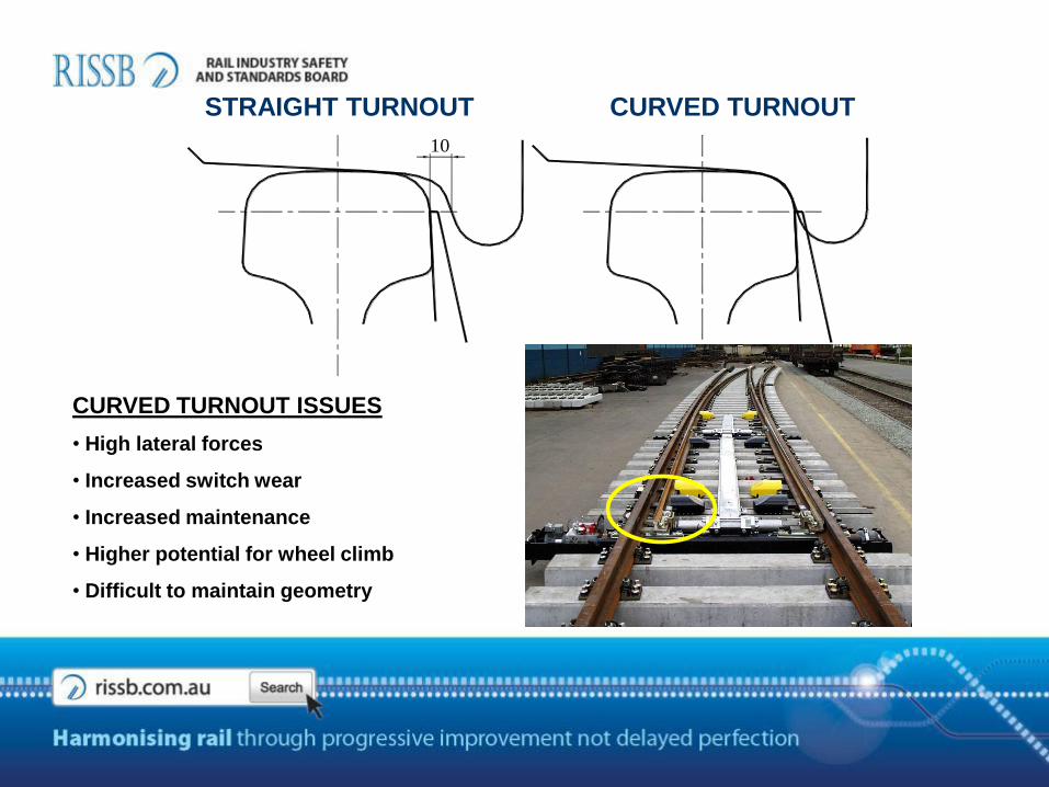
CURVED TURNOUT ISSUES
• High lateral forces
• Increased switch wear
• Increased maintenance
• Higher potential for wheel climb
• Difficult to maintain geometry
10
STRAIGHT TURNOUT CURVED TURNOUT
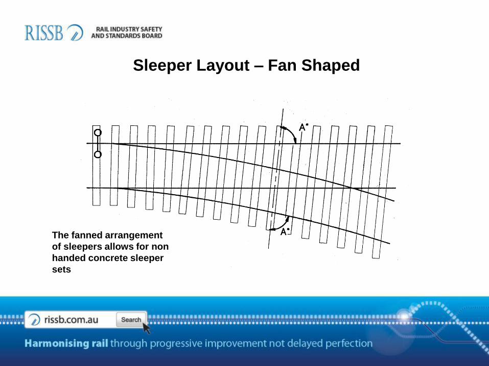
Sleeper Layout – Fan Shaped
The fanned arrangement
of sleepers allows for non
handed concrete sleeper
sets
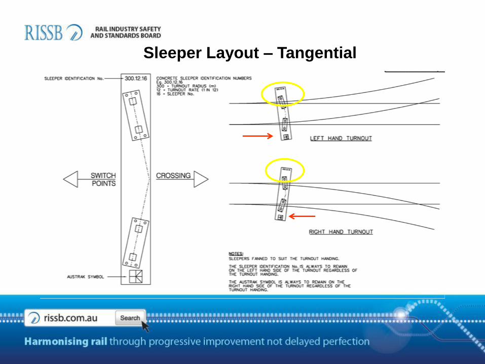
Sleeper Layout – Tangential
SWITCH TYPES
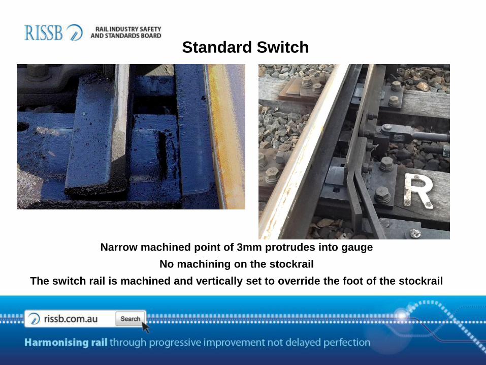
Standard Switch
Narrow machined point of 3mm protrudes into gauge
No machining on the stockrail
The switch rail is machined and vertically set to override the foot of the stockrail
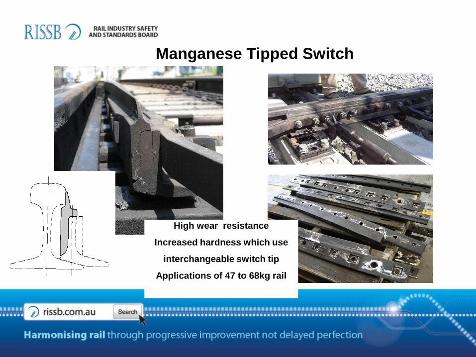
Manganese Tipped Switch
High wear resistance
Increased hardness which use
interchangeable switch tip
Applications of 47 to 68kg rail
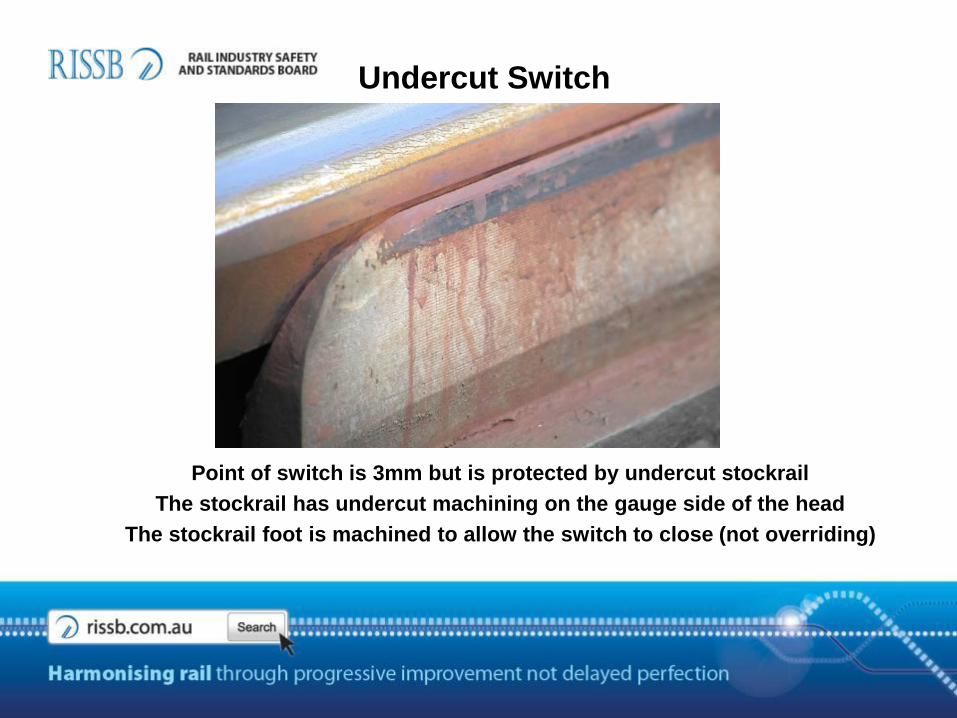
Undercut Switch
Point of switch is 3mm but is protected by undercut stockrail
The stockrail has undercut machining on the gauge side of the head
The stockrail foot is machined to allow the switch to close (not overriding)
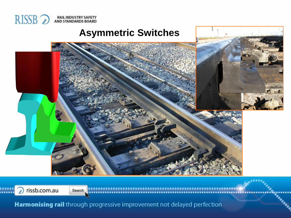
Asymmetric Switches
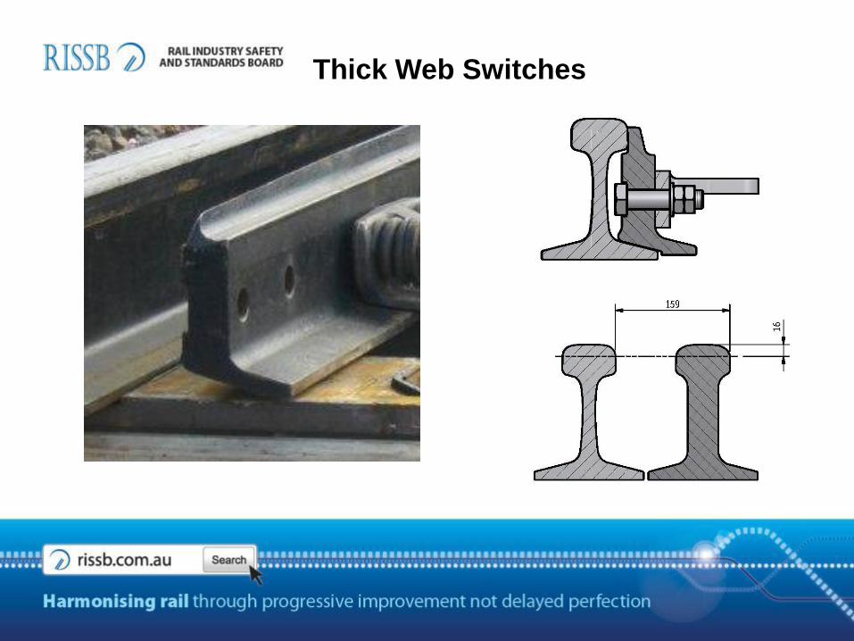
Thick Web Switches
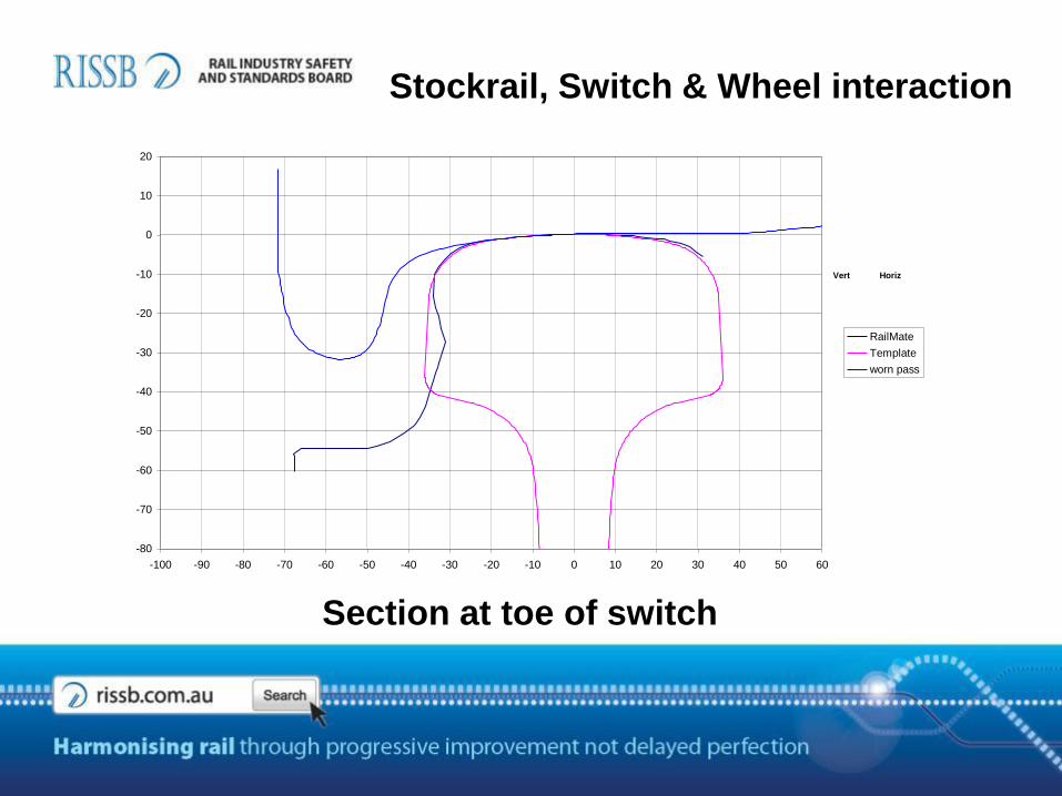
39, revesby, 30, Down
-80
-70
-60
-50
-40
-30
-20
-10
0
10
20
-100 -90 -80 -70 -60 -50 -40 -30 -20 -10 0 10 20 30 40 50 60
RailMate
Template
worn pass
Vert Horiz
Stockrail, Switch & Wheel interaction
Section at toe of switch
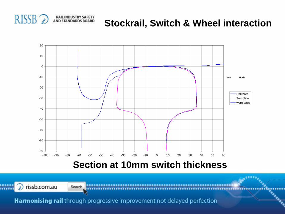
47, revesby, 2400, Down
-80
-70
-60
-50
-40
-30
-20
-10
0
10
20
-100 -90 -80 -70 -60 -50 -40 -30 -20 -10 0 10 20 30 40 50 60
RailMate
Template
worn pass
Vert Horiz
Stockrail, Switch & Wheel interaction
Section at 10mm switch thickness
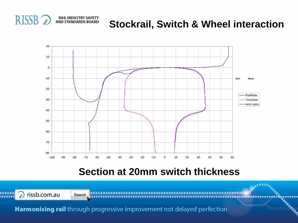
51, revesby, 3900, Down
-80
-70
-60
-50
-40
-30
-20
-10
0
10
20
-100 -90 -80 -70 -60 -50 -40 -30 -20 -10 0 10 20 30 40 50 60
RailMate
Template
worn pass
Vert Horiz
Stockrail, Switch & Wheel interaction
Section at 20mm switch thickness
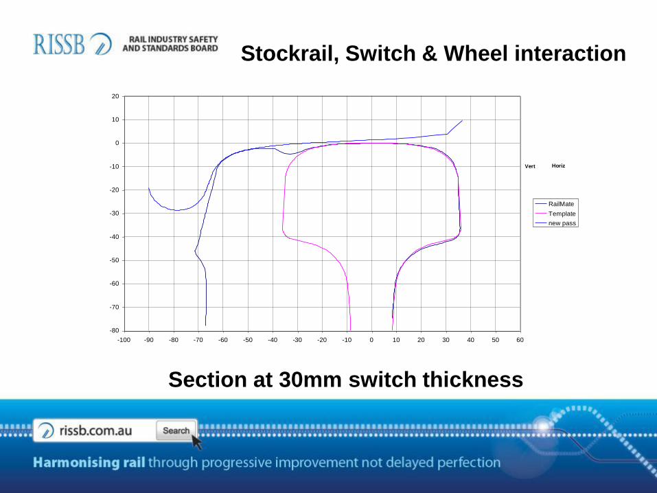
54, revesby, 4800, Down
-80
-70
-60
-50
-40
-30
-20
-10
0
10
20
-100 -90 -80 -70 -60 -50 -40 -30 -20 -10 0 10 20 30 40 50 60
RailMate
Template
new pass
Vert Horiz
Stockrail, Switch & Wheel interaction
Section at 30mm switch thickness
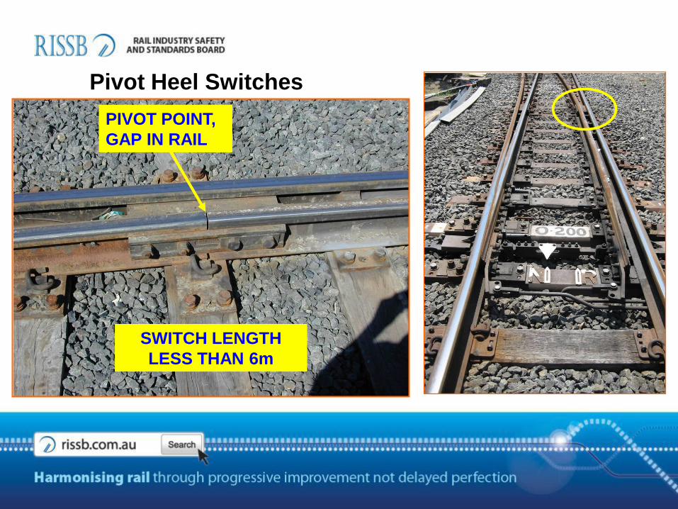
PIVOT POINT,
GAP IN RAIL
SWITCH LENGTH
LESS THAN 6m
Pivot Heel Switches
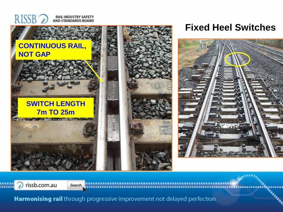
CONTINUOUS RAIL,
NOT GAP
SWITCH LENGTH
7m TO 25m
Fixed Heel Switches
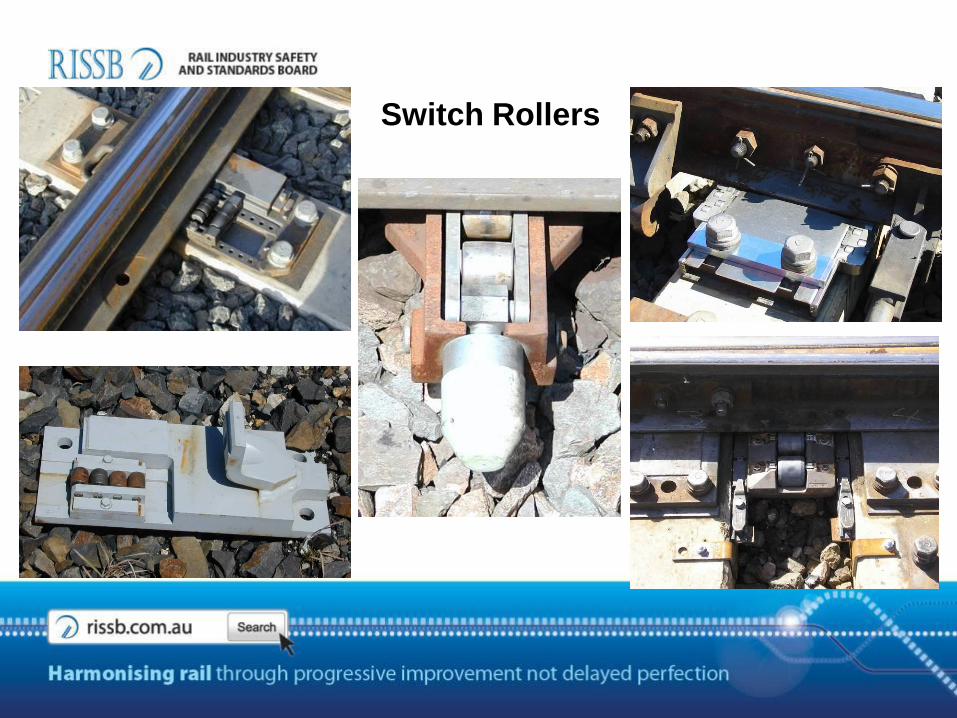
Switch Rollers
WESTINGHOUSE
M23A MACHINE
WESTINGHOUSE
T84M MACHINE
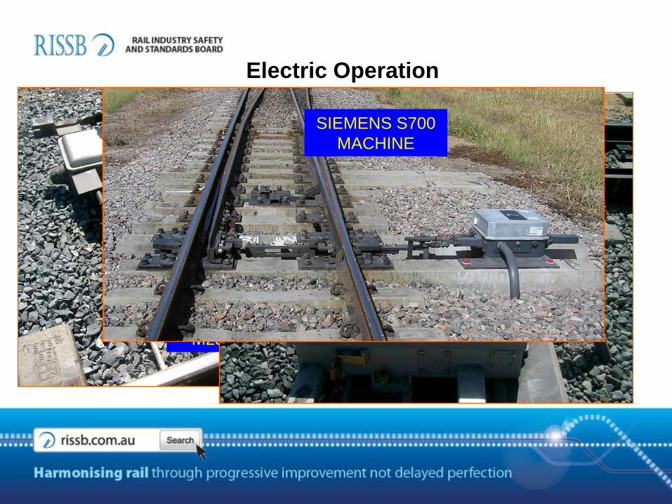
SIEMENS S700
MACHINE
Electric Operation

DETECTION HYDRAULIC
CYLINDER
Hydraulic Operation
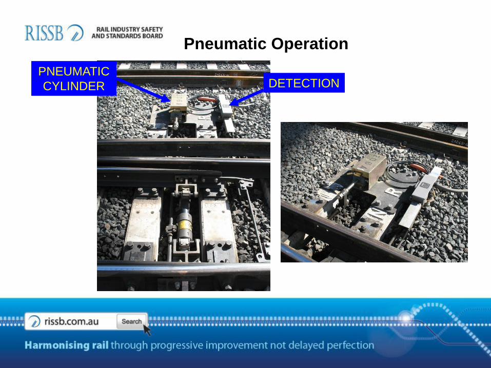
Pneumatic Operation
DETECTIONPNEUMATIC
CYLINDER

In-sleeper Operation
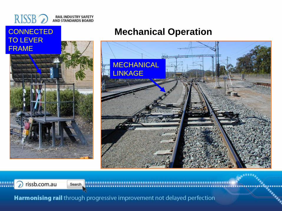
Mechanical Operation
MECHANICAL
LINKAGE
CONNECTED
TO LEVER
FRAME
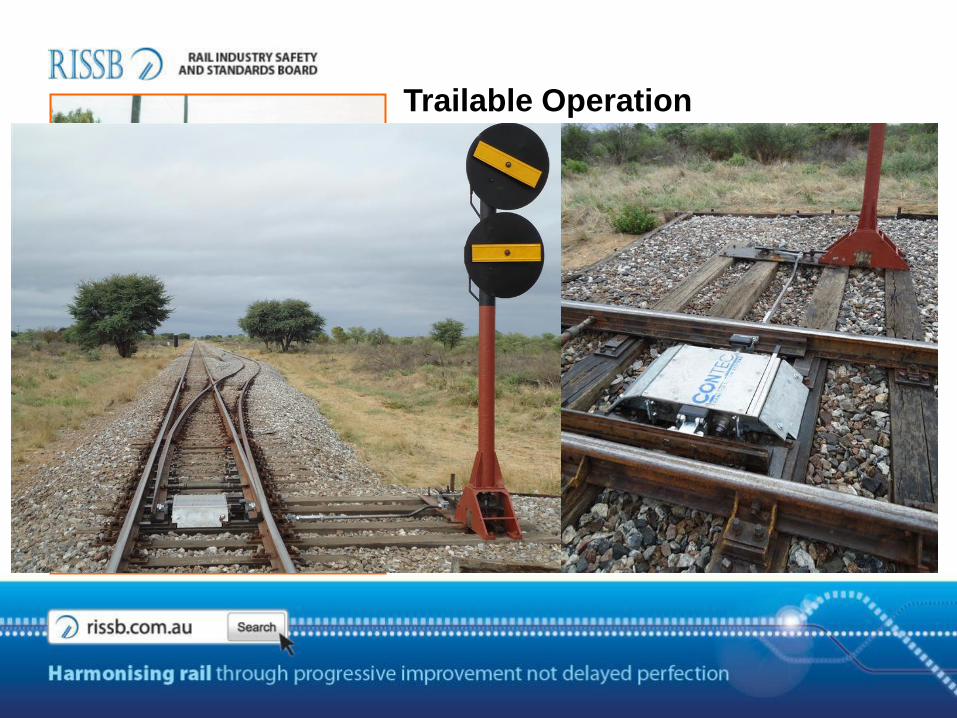
Trailable Operation
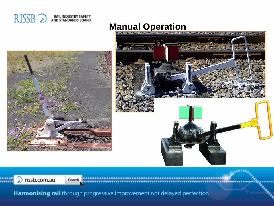
Manual Operation
CROSSING TYPES
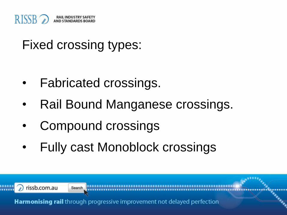
Fixed crossing types:
• Fabricated crossings.
• Rail Bound Manganese crossings.
• Compound crossings
• Fully cast Monoblock crossings

Point rail
Splice rail
Wing rails
rail
Chocks
Left hand crossing
Fabricated Crossing
FEATURES
• Available in rail sizes form 20 to 68kg
• Fabricated from rail steel & cast iron blocks
• Maximum recommended axle load capacity 20 tonne
• Maximum recommended mainline speed 80km
• Light duty applications and yards
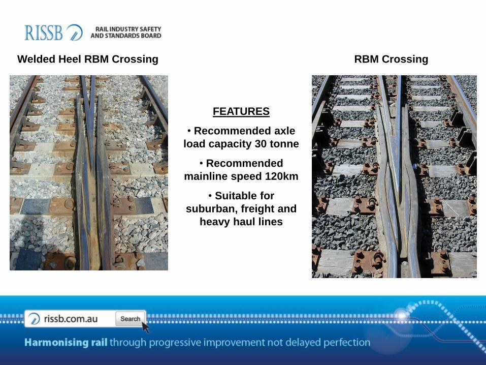
Welded Heel RBM Crossing RBM Crossing
FEATURES
• Recommended axle
load capacity 30 tonne
• Recommended
mainline speed 120km
• Suitable for
suburban, freight and
heavy haul lines

Manganese Crossing Nose
Stainless Steel Insert
Compound Crossings (MN Nose)
Rail Steel
Manganese Noses
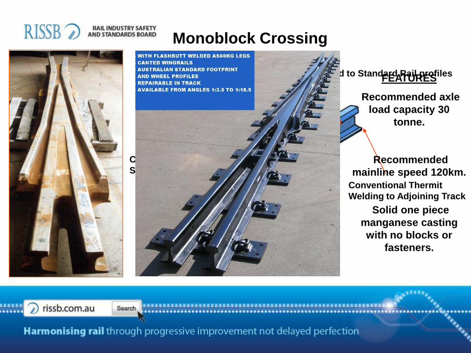
Monoblock Crossing
Base And Top Face
Full Machined
Flash Butt Weld to Standard Rail profiles
Explosive Depth
Hardened Transition
Faces
Cast Manganese
Section
Conventional Thermit
Welding to Adjoining Track
FEATURES
Recommended axle
load capacity 30
tonne.
Recommended
mainline speed 120km.
Solid one piece
manganese casting
with no blocks or
fasteners.
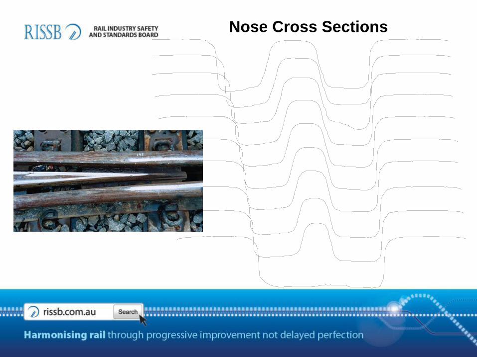
Nose Cross Sections
50
40
30
20
10
0
-110 -100 -90 -80 -70 -60 -50 -40 -30 -20 -10 0 10 20 30 40 50 60 70 80 90 100 110
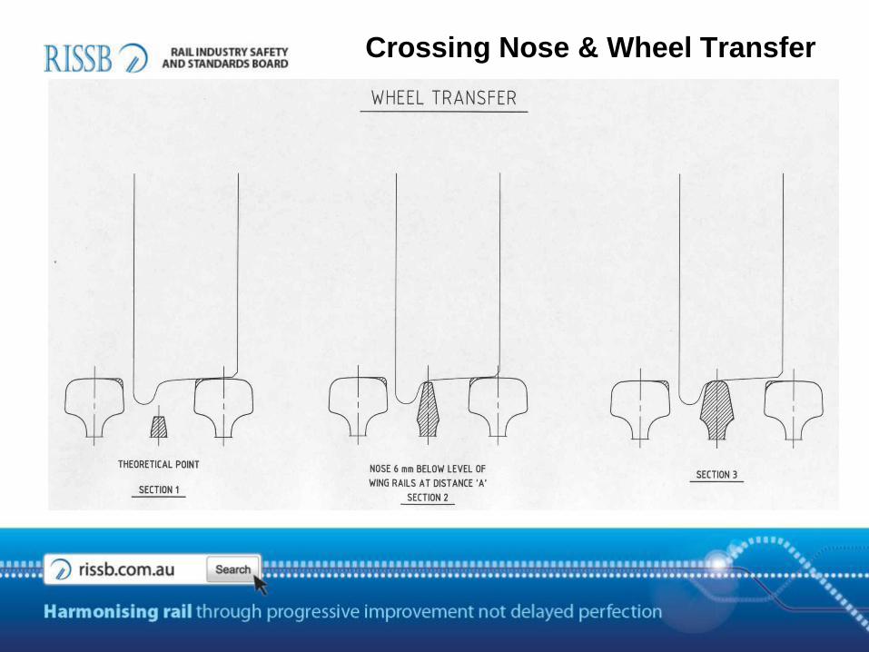
Crossing Nose & Wheel Transfer
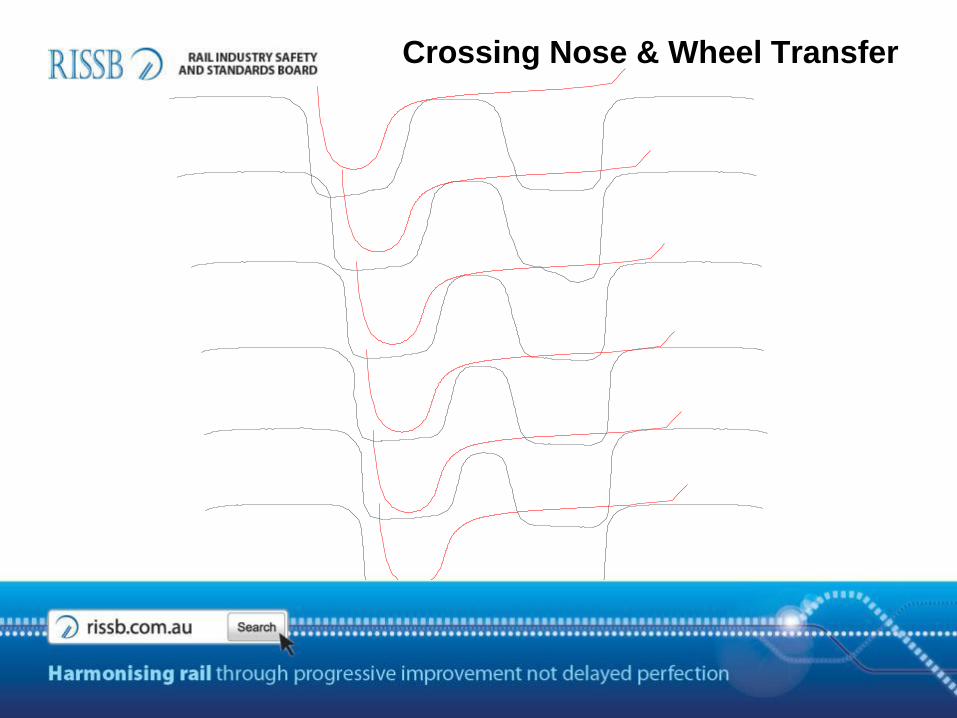
Crossing Nose & Wheel Transfer
50
40
30
20
10
0
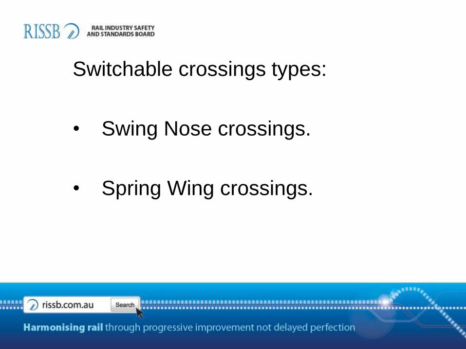
Switchable crossings types:
• Swing Nose crossings.
• Spring Wing crossings.
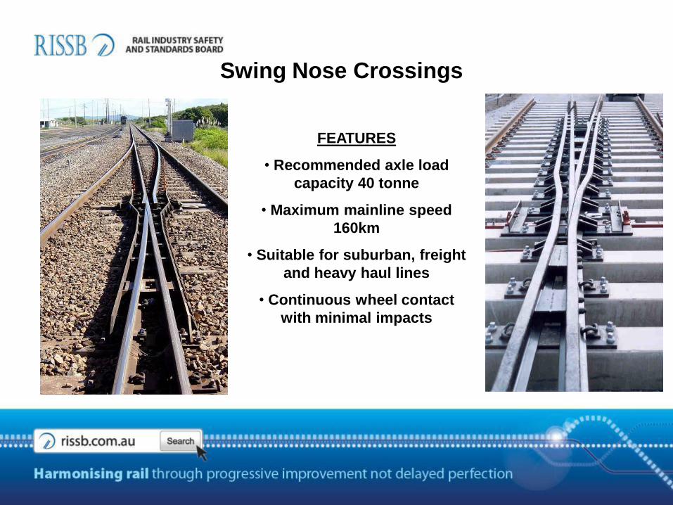
Swing Nose Crossings
FEATURES
• Recommended axle load
capacity 40 tonne
• Maximum mainline speed
160km
• Suitable for suburban, freight
and heavy haul lines
• Continuous wheel contact
with minimal impacts
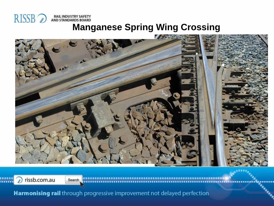
Manganese Spring Wing Crossing
• Designed for
predominate mainline
operation.
• Provides continuous
contact of wheel and
rail.
• Maximum mainline
speed of 120m/h.
• Maximum turnout
speed of 25m/h.
GUARDRAIL TYPES
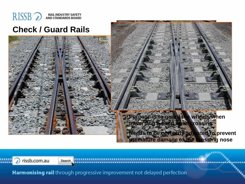
Check / Guard Rails
•Purpose is to guard the wheels when
traversing a fixed nose crossing
•Needs to be correctly adjusted to prevent
premature damage to the crossing nose
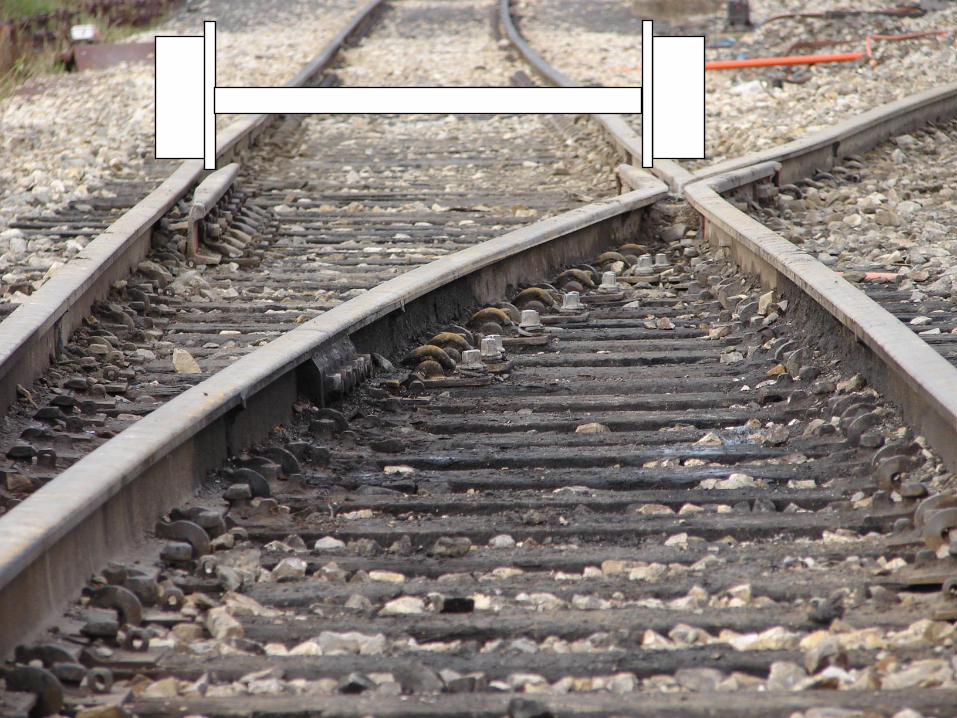

Effective Guard Rail Gauge
CrossingGuard Rails

Standard Guard Rail
• Manufactured from conventional rail section
• Difficult to adjust due to fastening method to stockrail
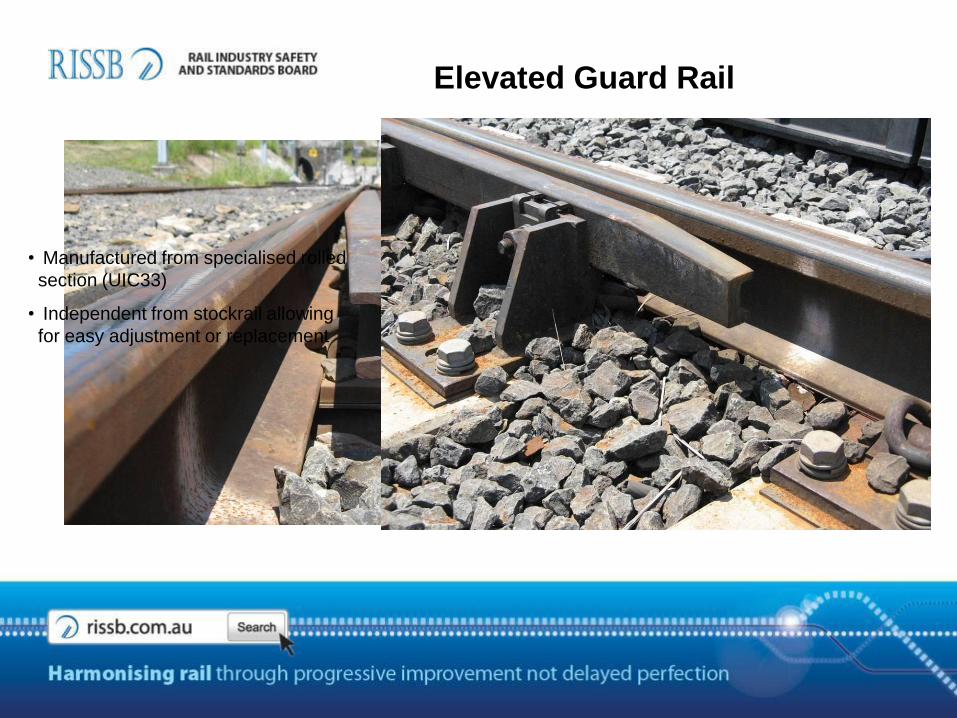
Elevated Guard Rail
• Manufactured from specialised rolled
section (UIC33)
• Independent from stockrail allowing
for easy adjustment or replacement
Questions
Turnout design can only improve !