richter optica u1 microscope user's manual · thank you for your purchase of a richter optica...
TRANSCRIPT

Richter Optica
Instructions for Models:U1B, U1T, U1D, U1LCD
Universty Student Biological Microscope
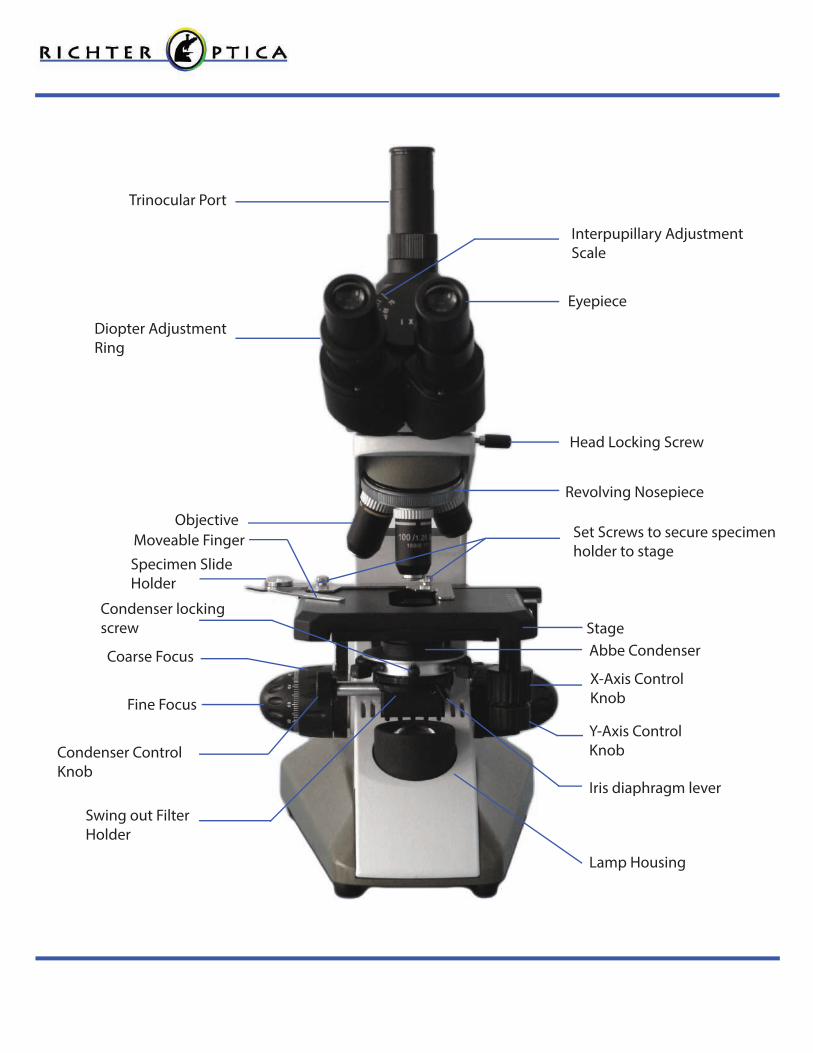
Revolving Nosepiece
Objective
Specimen Slide Holder
Stage
Eyepiece
Trinocular Port
Fine Focus
Coarse Focus
Diopter Adjustment Ring
Condenser Control Knob
X-Axis ControlKnob
Y-Axis Control Knob
Set Screws to secure specimen holder to stage
Head Locking Screw
Interpupillary Adjustment Scale
Iris diaphragm lever
Swing out Filter Holder
Abbe Condenser
Lamp Housing
Condenser locking screw
Moveable Finger

1
Thank you for your purchase of a Richter Optica microscope. The information in this manual is provided to answer most questions that can arise when operating your microscope and to help you avoid unneccesary maintenance expenses in the future.
Please carefully read instructions before operating microscope. Nomenclature used to describe components and controls are identi�ed on opposite page.
UNPACKING
Do not discard styrofoam container or packing materials until you are sure shipment is complete and undamaged (retain styrofoam shipping container to store your microscope when it is not in use). Remove all tape and packing material used to protect microscope during shipment. Make certain lens surfaces do not come in contact with dirt, �ngerprints or oil. Damage of lens surfaces occur when they come in contact with such contaminants, and image quality is reduced.
OPERATION
A. Illumination
1. Before operating microscope, adjust intensity control located on side of base to the minimum position. This should be done prior to each time the base is turned on or o�. This will extend bulb life. 2. Insert power plug into base of microscope. Then insert plug into outlet.
3. Push rocker switch at back of the base to on position.
4. Rotate intensity dial on illuminator base until the image is illuminated.
5. Adjust intensity of light to match requirements of objective and specimen slide.
B. Interpupillary Adjustment of Viewing Head
1. Looking through microscope, adjust distance between the two eyepieces by grasping the eyetubes and moving them either closer or farther apart.
2. When a full �eld of view is observed throught both tubes, and images blend into one, interpupillary distance is corrected for your eyes. Check the interpupillary scale and note index reading for future reference, in case other users will be changing this adjustment from time to time.
3. Adjust the diopter scales, located on each eyetube, to the same numerical value as indicated on the interpupillary scale. This must be done in order to maintain parfocality of objective lenses. If interpupillary distance is changed, adjust eyepiece diopters accordingly.
C. Focusing the Microscope
1. Position the 4x objective lens into the optical path, making sure that lens clicks into its proper position.

2
2. Place standard specimen slide (cover slip up) on top of stage surface.
a. Swing movable �nger on slide holder outward. Place specimen slide against �xed side of slide holder. Slowly release moveable �nger until it makes contact with the specimen slide.
3. Rotate coarse focusing controls until the specimen comes into focus.
4. Adjust �ne focus controls until specimen is in sharp focus.
5. Adjust diopter for di�erence in eyesight.
a. Using right eye, peer into the right eyepiece tube. Adjust sharpness of image by turning diopter adjustment located on left eyepiece tube.
6. Adjust the aperture (opening) of the iris diaphragm.
Iris diaphragm should not be used to control the brightness of illumination, use light intensity control knob to adjust light level. Iris diaphragms are designed to help achieve high resolution of specimen and provide contrast in the image. Smaller apertures will deliver contrast to the image. However, closing aperture too much will reduce resolution. Experimentation is the best method of determining the correct opening of the diaphragm. Some suggested openings for the iris diaphragm are:
7. Changing magni�cation.
a. Rotate revolving nosepiece to postition 10x objective into optical path.
b. This microscope has been parfocalized, which allows changes from one objective to another while requiring only a slight adjustment of the �ne focus controls.
c. When changing to the 40x and 100x objective lens, care must be exercised in order to prevent damaging the front lens element and specimen slide.
d. In order to obtain the maximum resolution of the 100x oil immersion lens, it is necessary to apply immersion oil between the cover glass of slide and the front lens of the objective.
1.) Use a very small amount of immersion oil. Only the tip of the lens should ever come in contact with the oil.
Objective
4x10x40x100x
Diaphragm Opening
1/8 open1/8 to 1/4 open1/4 to 1/2 open1/2 to 3/4 open

3
1. Optical Maintenance a. Do not attempt to disassemble any lens component. Consult an expert technical service company when repairs not covered by these instructions are required.
b. Prior to cleaning any lens surface, brush dust or dirt o� lens surfaces using a camel hair brush. Or use air to blow dust and lint o� surfaces. Compressed air, available at any computer supply store, is a good source of clean air.
c. Cleaning eyepiece lenses. Do not remove eyepiece from eyepiece tube. Clean only the outer surface. Breathe on lens to dampen surface, then wipe with lens paper. Do not wipe lens surface while dry as lenses are scratched very easily. Wipe in a circular motion from center to outer edges.
d. Cleaning objective lenses.
Do not remove objective lenses from the microscope. Clean front lens element only. Using a cotton swab saturated with distilled water, clean front lens surface. Inspect the lens using a magnifying glass to ensure that the element is clean. If immersion oil or specimen material of any kind is evident, use a cotton swab dipped in a small amount of Windex to clean all foreign material from objective lens surface. Such material will reduce or totally block image quality.
e. Cleaning condenser lens.
Clean only the top lens surface, visible when looking through hole in top of stage. Use same procedure as used for eyepiece or objective lenses.
f. Illuminator condenser lens.
Use same procedure as used for eyepiece or objective lenses.
2. Electrical Maintenance WARNING: FOR YOUR SAFETY, TURN SWITCH OFF AND REMOVE PLUG FROM POWER SOURCE OUTLET BEFORE MAINTAINING YOUR MICROSCOPE.
1. Replacement of Bulb Detailed instructions for bulb replacement can be found on page 6 of this manual. Replacment bulb part #: U1-001.

4
2. Replacement of Fuse
The fuse is located on the back of the microscope on the right side of the power plug. To remove the fuse from the holder, insert a 6mm screwdriver blade into slot located in rear of fuse cap. Slightly depress and rotate screwdriver to release the fuse cap. Pull cap and fuse out of fuse holder. Insert proper 1 amp electronic fuse into fuse cap. Using screwdriver, rotate fuse cap assembly in opposite direction of arrow until guide slot engages, depress fuse cap and rotate 1/4 turn to lock into fuse.
TROUBLESHOOTING
ELECTRICAL
Problem Reason for Problem Solution
Light burns out too soon
Light bulb burns out immediately
Light Flickers
The voltage is too high.
Incorrect lamp used.
Lamp not properly inserted into socket.
Lamp about to burn out.
Fuse holder not locked into proper position.
Loose connection at AC outlet.
Adjust intensity control to the minimum position before turning the power switch on.
Have quali�ed service technician use proper bulb. Plug unit into proper outlet 120v or 220v.
Have quali�ed service technician make repairs.
Problem Reason for Problem Solution
Light Fails to Operate Outlet inoperative.
AC Power cord not connected.
Bulb burned out.
Fuse burned out.
Fuse burns out too soon.
Fuse blows instantly when replaced.
Have quali�ed service technician repair outlet.
Plug into outlet.
Replace with new LED bulb.
Replace with new 1 amp fuse.
Replace with proper 1 amp fuse.
Unit has short, have quali�ed service technician repair electrical short.

5
TROUBLESHOOTING
IMAGE QUALITY
MECHANICAL PROBLEM
Spots in �eld of view
Uneven illumination of �eld
Eyepiece dirty.
Specimen slide dirty.
Condenser lens dirty.
Nosepiece not properly indexed.
Diaphragm not properly indexed.
Problem Reason for Problem Solution
Does not stay in focus Stage drops down. Adjust tension adjustment knob.
Problem Reason for Problem Solution
No Image
Poor Resolution (Image not sharp)
Nosepiece not indexed properly.
Light too bright.
Objective lens dirty.
Eyepiece lens dirty.
Slide upside down.
Cover slip on specimen slide too thick.
Too much light.
Condenser lens dirty.
Rack stop not set at a proper position.
Move revolving nosepiece until objective lens clicks into position.
Adjust light intensity control to a lower position.
Clean objective lens.
Clean eyepiece lens.
Turn specimen slide over cover slip facing up.
Use 0.17mm thick cover slip.
Adjust light intensity control to a lower position.
Clean condenser lens.
Adjust rack stop.
0.00.20.40.60.81.0
Clean eyepiece lens.
Clean slide.
Clean lens of condenser.
Revolve nosepiece into positive index stop.
Adjust diaphragm to proper level.

6
Replacement of LED Bulb 1. Turn o� the microscope.
2. Lift the light housing as shown at right.
3. Notice the “+” and “-” markings and positioning of the current bulb. The replacement bulb will be inserted the same way.
4. Unscrew the two screws connecting the bulb assembly to the base plate.
5. Cut the wires connecting the old bulb assembly, as shown by the red arrow in the photo at right.
6. Connect the new wire by soldering or twisting it together (red to red and white to blue). Once wires have been soldered, wrap electrical tape around each wire.
7. Screw LED assembly plate back into place.
8. Replace light housing cover.
Replacement LED Assembly part # U1-001 (shown at bottom right).