rg-wlan series access point web-based configuration guide
TRANSCRIPT

RG-WLAN Series Access Point
Web-Based Configuration Guide
Release 10.4 (1b19)p2
Version: V3.0

Copyright Statement
Ruijie Networks©2014
Ruijie Networks reserves all copyrights of this document. Any reproduction, excerption, backup, modification,
transmission, translation or commercial use of this document or any portion of this document, in any form or by any means,
without the prior written consent of Ruijie Networks is prohibited.
, , , , ,
, , , ,
, , are registered trademarks of Ruijie Networks.
Counterfeit is strictly prohibited.
Exemption Statement
This document is provided “as is”. The contents of this document are subject to change without any notice. Please obtain
the latest information through the Ruijie Networks website. Ruijie Networks endeavors to ensure content accuracy and will
not shoulder any responsibility for losses and damages caused due to content omissions, inaccuracies or errors.

Preface
Thank you for using our products. This manual matches the RGOS 10.4 (1b19)p2.
Audience
This manual is intended for:
Network engineers
Technical support and servicing engineers
Network administrators
Obtaining Technical Assistance
Ruijie Networks website: http://www.ruijienetworks.com/
Online customer services: http://webchat.ruijie.com.cn
Customer service center: http://www.ruijie.com.cn/service.aspx
Customer services hotline: +86-4008-111-000
BBS: http://support.ruijie.com.cn
Customer services email: [email protected]
Related Documents
Documents Description
Command Reference Describes the related configuration commands, including command
modes, parameter descriptions, usage guides, and related examples.
Hardware Installation and Reference
Guide
Describes the functional and physical features and provides the device
installation steps, hardware troubleshooting, module technical
specifications, and specifications and usage guidelines for cables and
connectors.
Conventions
This manual uses the following conventions:
Convention Description
boldface font Commands, command options, and keywords are in boldface.
italic font Arguments for which you supply values are in italics.
[ ] Elements in square brackets are optional.
{ x | y | z } Alternative keywords are grouped in braces and separated by vertical
bars.
[ x | y | z ] Optional alternative keywords are grouped in brackets and separated by
vertical bars.
Symbols
Means reader take note. Notes contain helpful suggestions or references.
Means reader be careful. In this situation, you might do something that could result in equipment
damage or loss of data.

Configuration Guide Configuring Web Management
Configuring Web Management
Understanding Web Management
Overview
Web management manages wireless network devices through browsers like IEs.
Working Principle
Web management involves a Web server and Web clients. The Web server is deployed on an AP to receive and
process requests from Web clients (reading Web files or executing request commands), and returns processing
results to the clients. A Web client usually refers to a Web browser, such as an IE.
Protocol Specification
None
Requirements for Clients
Administrators usually log in to the AP Web management interface through a client Web browser to manage
the AP. Clients are often PCs or other mobile terminal devices, such as a laptop or an iPad.
Browsers include Google Chrome, Firefox, and IEs, including IE6.0, IE7.0, IE8.0, and IE core-based
browsers like Maxthon
The recommended resolutions are 1024x768, 1280x1024, and 1440x960. Other resolutions may make
characters and formats on pages unaligned and unpleasant.
Requirements for Server
The Web service needs to be enabled on the AP.
Web login authentication information needs to be configured on the AP.
A management IP address needs to be configured on the AP.
Default Configuration
Web service is enabled by default. You can enter 192.168.110.1 in address bar of the browser. Please refer to
Typical Configuration Examples of Web Management for specific CLI configuration steps.
Default Username and Password Description
admin / admin Administrator with all permissions

Configuration Guide Configuring Web Management
If the first configuration for an AP is not performed through Web (such as CLI configuration and the
associated AC configuration), the AP will disable the Web service. If you want to manage the AP
through Web later, please enable Web service manually.
When entering values of configuration items (such as port description and VLAN description) via CLI,
please try not to use spaces. Otherwise an error may occurred in Web Management.
Configuring Web Management
Enter the management IP address of the AP (such as http://192.168.110.1) into the browser address bar and
press Enter to display the following page.
Figure 1 Initial Interface
Please enter your user name and password and click Login. If you pass the authentication, the system home
page is displayed. When logging in to the system at the first time, you enter the Configuration Wizard interface.
When logging in again, you enter the monitoring home page.
System Home Page
Click the System Home Page menu to enter the following page.

Configuration Guide Configuring Web Management
Figure 2 System Home Page
Configuration description: System Home Page helps users learn about AP status and general network
information as follows:
AP resource status
Interface traffic tendency
Current client status
AP resource status: Display the CPU utilization of the current AP, sizes of the available memory and flash
memory, and the number of online STAs..
Interface traffic tendency: Display the real-time tendency of received and sent traffic on the port specified in the
drop-down box.
Current user status: Display the proportion of STAs with strong RSSI, middle RSSI, and low RSSI.
Configuration Wizard
Click the Configuration Wizard menu to enter the configuration wizard home page, where the Configuration
Steps can be executed.
Configuration Wizard will guide you to complete the Wireless Smart Web network deployment.

Configuration Guide Configuring Web Management
Configuration Steps
Figure 3 Configuration Steps
Configuration description: WiFi name (SSID): Configure a name for a wireless network.
WiFi Password: The authentication password that user entered to associate the WiFi
DHCP service: If there is no DHCP server in the network, enable the DHCP service for the wireless network.
Configuration Steps
Monitoring
Client Info
Click the Client Info menu to enter the following page.
Figure 5 Client Info
Configuration description:
Details: To check details about the specified STA.
Block: Add the STA to the blacklist.
Configuration Guide Configuring Web Management
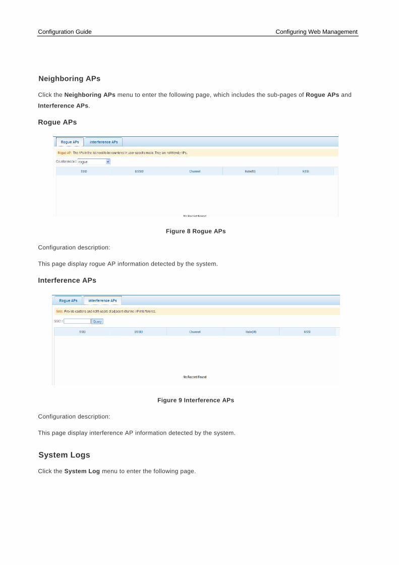
Neighboring APs
Click the Neighboring APs menu to enter the following page, which includes the sub-pages of Rogue APs and
Interference APs.
Rogue APs
Figure 8 Rogue APs
Configuration description:
This page display rogue AP information detected by the system.
Interference APs
Figure 9 Interference APs
Configuration description:
This page display interference AP information detected by the system.
System Logs
Click the System Log menu to enter the following page.

Configuration Guide Configuring Web Management
Figure 10 System Logs
Configuration description
You can query the system log by entering the keyword.
Network Configuration
Port Management
Click the Port Configuration menu to enter the following page, which includes the sub-pages of Basic
Configuration, Port Aggregation and Port Mirroring.
Figure 11 Port Management
Configuration description:
Edit a port: Click Edit in the table above to open the window of Figure 12.

Configuration Guide Configuring Web Management
Figure 12 Port Editing
Check port details: Click Details in the table above to open the window of Figure 13.
Figure 13 Port Details
VLAN Management
Click the VLAN Management menu to enter the following page.
VLAN Settings

Configuration Guide Configuring Web Management
Figure 14 VLAN Settings
Configuration description:
Add a VLAN: Enter a VLAN ID, a VLAN name, an IPv4 address, and an IPv6 address into the upper form on the
page, and click Add to finish the addition operation.
Edit a VLAN: Click Edit in the table above, and the table displays the parameters of the specified VLAN. Then
click the Edit button to finish the editing operation.
Delete a VLAN: Click Delete in the table above, and click OK in the displayed dialog box to finish the deletion
operation.
Route Configuration
Click Route Configuration to enter the following page, which includes the sub-pages of IPv4 Route and IPv6
Route.
IPv4 Route

Configuration Guide Configuring Web Management
Figure 15 IPv4 Route
Configuration description:
Click Create Static Route to open the window of Figure 16. Click Create Default Route to open the window of
Figure 34. To delete a specified route, click Delete in the table above and click OK in the displayed dialog box.
Figure 16 Create Static Route
Figure 17 Create Default Route
IPv6 Route
Figure 18 IPv6 Route
Configuration description:

Configuration Guide Configuring Web Management
Click Create Static Route to open the window of Figure 19. Click Create Default Route to open the window of
Figure 20. To delete a specified route, click Delete and click OK in the displayed dialog box.
Figure 19 Create Static Route
Figure 20 Create Default Route
DHCP Configuration
Click the DHCP Configuration menu to enter the following page, which includes the sub-pages of Basic
Configuration, Static Address, Reserved Address, Client Display, and DHCP SNOOPING.
Basic Configuration
Figure 21 Basic Configuration
Configuration description:

Configuration Guide Configuring Web Management
Add a DHCP server: Click Create DHCP Server to open the window of Figure 22. Configure parameters and click
OK to finish the addition operation.
Edit a DHCP server: Click Edit in the table above to open the Edit DHCP Server window, and click OK to finish
the editing operation.
Delete a DHCP server: Click Delete in the table above and click OK in the displayed dialog box to finish the
deletion operation.
Figure 22 Create DHCP Server
If you select the “DHCP Relay” networking mode, the Create DHCP Server link below is changed to Create
DHCP Relay, and the DHCP server form is changed to the DHCP relay form.
Add a DHCP relay agent: Click Create DHCP Relay to open the window of Figure 23. Configure parameters and
click OK to finish the addition operation.
Edit a DHCP relay agent: Click Edit in the DHCP relay table to open the Edit DHCP Relay window and click OK
to finish the editing operation.
Delete a DHCP relay agent: Click Delete in the DHCP relay table and click OK in the displayed dialog box to
finish the deletion operation.

Configuration Guide Configuring Web Management
Figure 23 Create DHCP Relay
Static Address Configuration
Figure 24 Static Address Configuration
Configuration description:
Add static address allocation: Enter parameters into the upper form on the page and click Add to finish the
addition operation.
Edit static address allocation: Click Edit in the table above, and the upper form displays allocation information
about the specified static address. Then click Edit to finish the editing operation.
Delete static address allocation: Click Delete in the table above and click OK in the displayed dialog box to finish
the deletion operation.
Reserved Address
Figure 25 Reserved Address
Configuration description:
Add a reserved address: Enter parameters into the upper form on the page and click Add to finish the addition
operation.
Edit a reserved address: Click Edit in the table above, and the form displays information about the specified
reserved address. Then click Edit to finish the editing operation.
Delete a reserved address: Click Delete in the table above and click OK in the displayed dialog box to finish the
deletion operation.

Configuration Guide Configuring Web Management
Client Display
Figure 26 Client Display
Configuration description:
The table displays the MAC address, the assigned IP Address, address lease time and other information about
an online client.

Configuration Guide Configuring Web Management
DHCP SNOOPING
Figure 27 DHCP SNOOPING
Configuration description:
Click Configure Trusted Port to open the window of Figure 28, and click Configure IP Source Guard to open
the window of Figure 29.
Figure 28 Configure Trusted Port

Configuration Guide Configuring Web Management
Figure 29 Configure IP Source Guard
Wireless Configuration Management
WLAN Management
Click the WLAN Management menu to enter the following interface.
Figure 30 WLAN Management
Configuration description:
Configuration Guide Configuring Web Management
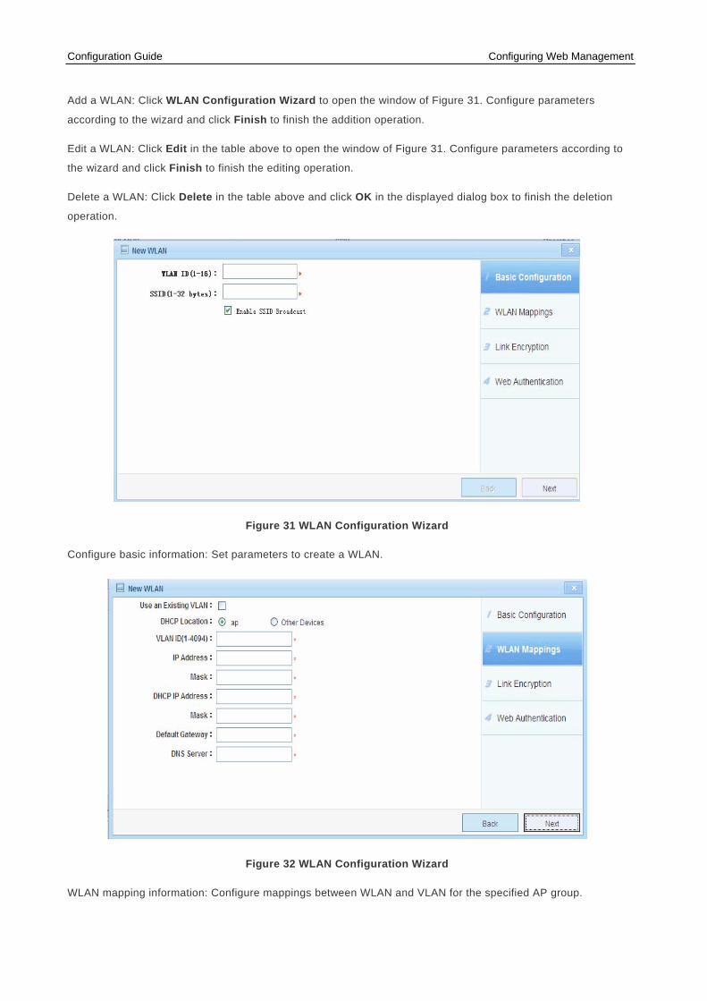
Add a WLAN: Click WLAN Configuration Wizard to open the window of Figure 31. Configure parameters
according to the wizard and click Finish to finish the addition operation.
Edit a WLAN: Click Edit in the table above to open the window of Figure 31. Configure parameters according to
the wizard and click Finish to finish the editing operation.
Delete a WLAN: Click Delete in the table above and click OK in the displayed dialog box to finish the deletion
operation.
Figure 31 WLAN Configuration Wizard
Configure basic information: Set parameters to create a WLAN.
Figure 32 WLAN Configuration Wizard
WLAN mapping information: Configure mappings between WLAN and VLAN for the specified AP group.

Configuration Guide Configuring Web Management
Figure 33 WLAN Configuration Wizard
Web authentication configuration: Configure the security mode and confirm whether to enable Web
authentication for the specified WLAN.
Radio1
Click the Radio1 menu to enter the following page, which includes the sub-pages of RF Configuration, Rate
Configuration and WDS Configuration.
RF Configuration

Configuration Guide Configuring Web Management
Figure 34 Radio 1
Configuration description:
The table above displays online APs. Click Config Radio to open the window of Figure 35. Enter parameters
and click OK to configure Radio 1 for the specified AP.
Rate Configuration
Click the Rate Configuration menu to enter the following interface.

Configuration Guide Configuring Web Management
Figure 35 Rate Configuration
Configuration description:
802.11a:
Tick required rates and click OK to finish the 802.11a rate configuration.
802.11b:
Tick required rates and click OK to finish the 802.11b rate configuration.
802.11g:
Tick required rates and click OK to finish the 802.11g rate configuration.
802.11n:
Enter the basic MCS index and click OK to finish the 802.11n rate configuration.
WDS Configuration
Figure 36 WDS Configuration
Wireless Distribution System (WDS) connects multiple APs in wireless bridging or relay mode so as to connect
distributed networks and extend wireless signals.

Configuration Guide Configuring Web Management
Radio2
Click the Radio2 menu to use this function. Radio 2 configuration is similar to Radio1configuration.
Security Configuration
ACL
Click the ACL menu to enter the following interface, which includes the sub-pages of ACL Validity Time and
Access Control List.
Configuration Guide Configuring Web Management
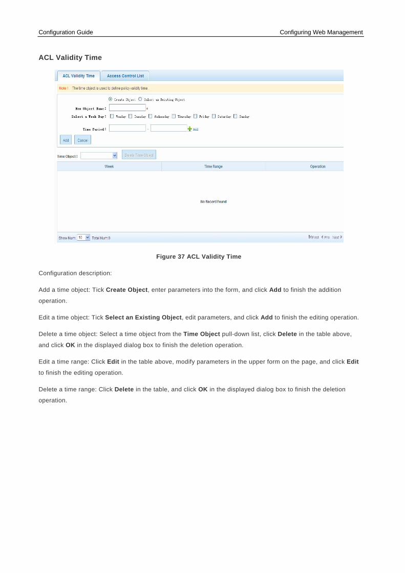
ACL Validity Time
Figure 37 ACL Validity Time
Configuration description:
Add a time object: Tick Create Object, enter parameters into the form, and click Add to finish the addition
operation.
Edit a time object: Tick Select an Existing Object, edit parameters, and click Add to finish the editing operation.
Delete a time object: Select a time object from the Time Object pull-down list, click Delete in the table above,
and click OK in the displayed dialog box to finish the deletion operation.
Edit a time range: Click Edit in the table above, modify parameters in the upper form on the page, and click Edit
to finish the editing operation.
Delete a time range: Click Delete in the table, and click OK in the displayed dialog box to finish the deletion
operation.

Configuration Guide Configuring Web Management
Access Control List
Figure 38 Access Control List
Configuration description:
Add an ACL: Click Create ACL to open the window of Figure 39, enter parameters, and click OK to finish the
addition operation.
Edit an ACL: Click Edit Rule in the table above to open the window of Figure 41, edit parameters and click OK to
finish the editing operation.
Delete an ACL: Click Delete in the table above and click OK in the displayed dialog box to finish the deletion
operation.
Figure 39 New ACL

Configuration Guide Configuring Web Management
Figure 40 Standard IP ACL
Figure 41 Add Rule
AP Containment
Click the AP Containment menu to enter the following page.
Figure 42 AP Containment
Configuration description:

Configuration Guide Configuring Web Management
Configure AP containment: Click Enable in the table above to open the window of Figure 42. Select a
containment mode and click Save to finish the configuration.
Blacklist and Whitelist Configuration
Click the Blacklist and Whitelist Configuration menu to enter the following page, which includes the sub-pages
of IDS, Static Blacklist, Dynamic Blacklist, and Whitelist.
IDS
Figure 43 IDS
Configuration description:
When IDS detects an attack, you can identify the attack source according to attack statistics and add it to the
blacklist. Alternatively, you can enable the dynamic blacklist function, so that the device automatically adds the
attack source to the blacklist.
Attack detection statistics: Display detected attack information according to the configured attack detection
mode.
Static Blacklist
Figure 44 Static Blacklist
Configuration description:

Configuration Guide Configuring Web Management
Add an STA to a static blacklist: Enter an STA MAC address into the form above and click Add to finish the
addition operation.
Delete an STA from a static blacklist: Click Delete in the table above and click OK in the displayed dialog box to
finish the deletion operation.
Dynamic Blacklist
Figure 45 Dynamic Blacklist
Configuration description:
Configure a dynamic blacklist: Enter parameters and click Save to configure a dynamic blacklist.

Configuration Guide Configuring Web Management
Whitelist
Figure 46 Whitelist
Configuration description:
Add an STA to a whitelist: Enter an STA MAC address into the form above and click Add to finish the addition
operation.
Delete an STA from a whitelist: Click Delete in the table above and click OK in the displayed dialog box to finish
the deletion operation.
User Isolation Policy
Click the User Isolation Policy menu to enter the following page.
Figure 47 User Isolation Policy
Configuration description:
Configure the isolation function: Select an isolation type and click Save to configure the isolation function.
Configure isolation-enabled users: Add isolation-enabled users.
ARP Management
Click the ARP Management menu to enter the following page.

Configuration Guide Configuring Web Management
ARP Management
Figure 48 ARP Management
Configuration description:
Add an ARP entry: Enter an STA MAC address into the form above and click Add to finish the addition operation.
Delete an ARP entry: Click Delete in the table above and click OK in the displayed dialog box to finish the
deletion operation.
Dynamic-to-static binding for an ARP entry: Select the ARP entry and click Dynamic>>Static Binding to finish
the configuration.
Delete all dynamic entries: Click Delete ALL Dynamic Entries and click OK in the displayed dialog box to finish
the deletion operation.
ARP Anti-Attack
Click the ARP Anti-Attack menu to enter the following page, which includes the sub-pages of Gateway
Anti-ARP-Attack and Anti-User-Attack.
Gateway Anti-ARP-Attack

Configuration Guide Configuring Web Management
Figure 49 Gateway Anti-ARP-Attack
Configuration description:
Add gateway anti-ARP-attack: Select ports on the panel, enter a gateway address, and click Add to finish the
addition operation.
Delete gateway anti-ARP-attack: Click Delete in the table above and click OK in the displayed dialog box to finish
the deletion operation.

Configuration Guide Configuring Web Management
Anti-User-Attack
Figure 50 Anti-User-Attack
Configuration description:
Edit anti-user-attack: Click Edit in the table above to open the window of Figure 51. Select Anti-User-Attack
status and click OK to configure defense against user ARP attacks.
View ARP attack list: Click View the ARP-Check Binding List to open the window of Figure 52.
Figure 51 Configuration Desctiption

Configuration Guide Configuring Web Management
Figure 52 Attack-check Binding List
NFPP
Click the NFPP menu to enter the following page, which includes the sub-pages of ARP Attack Defense, Anti-IP
Scanning, ICMP Attack Defense, DHCPv4 Attack Defense, DHCPv6 Attack Defense, and ND Attack
Defense.

Configuration Guide Configuring Web Management
ARP Attack Defense
Figure 53 ARP Attack Defense
Configuration description:
Set parameters and click Save to configure the ARP attack defense function. The table at the bottom of the page
displays monitoring information after ARP attack defense is enabled.
Anti-IP Scanning
Figure 54 Anti-IP Scanning
Configuration description:
Set parameters and click Save to configure the anti-IP scanning function. The table at the bottom of the page
displays monitoring information after anti-IP scanning is enabled.
Configuration Guide Configuring Web Management
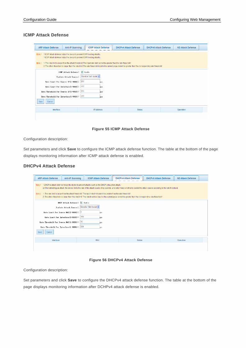
ICMP Attack Defense
Figure 55 ICMP Attack Defense
Configuration description:
Set parameters and click Save to configure the ICMP attack defense function. The table at the bottom of the page
displays monitoring information after ICMP attack defense is enabled.
DHCPv4 Attack Defense
Figure 56 DHCPv4 Attack Defense
Configuration description:
Set parameters and click Save to configure the DHCPv4 attack defense function. The table at the bottom of the
page displays monitoring information after DCHPv4 attack defense is enabled.

Configuration Guide Configuring Web Management
DHCPv6 Attack Defense
Figure 57 DHCPv6 Attack Defense
Configuration description:
Set parameters and click Save to configure the DHCPv6 attack defense function. The table at the bottom of the
page displays monitoring information after DCHPv6 attack defense is enabled.
ND Attack Defense
Figure 58 ND Attack Defense
Configuration description:
Set parameters and click Save to configure the ND attack defense function.
Rate Limit Configuration
Click the QOS menu to enter the following page, which includes the sub-pages of WLAN Bandwidth Policy, AP
Bandwidth Policy, and Client Bandwidth Policy.

Configuration Guide Configuring Web Management
WLAN Bandwidth Policy
Figure 59 WLAN Bandwidth Policy
Configuration description:
Edit WLAN bandwidth policies: Click Edit in the table above to open the window of Figure 60. Set parameters and
click OK to finish the editing operation.
Clear WLAN bandwidth policies: Click Clear Policies in the table above and click OK in the displayed dialog box
to finish the clearing operation.
Figure 60 WLAN 1 Bandwidth Policy
Client Bandwidth Policy

Configuration Guide Configuring Web Management
Figure 61 Client Bandwidth Policy
Configuration description:
Add client bandwidth policies: Click Create Policy to open the window of Figure 62. Set parameters and click OK
to finish the addition operation.
Edit client bandwidth policies: Click Edit in the table above to open the Edit Client Bandwidth Policy window.
Set parameters and click OK to finish the editing operation.
Delete client bandwidth policies: Click Delete in the table above and click OK in the displayed dialog box to finish
the deletion operation.
Figure 62 Create Client Bandwidth Policy
Authentication
AAA
Click the AAA menu to enter the following page.
Figure 63 AAA
Configuration Guide Configuring Web Management
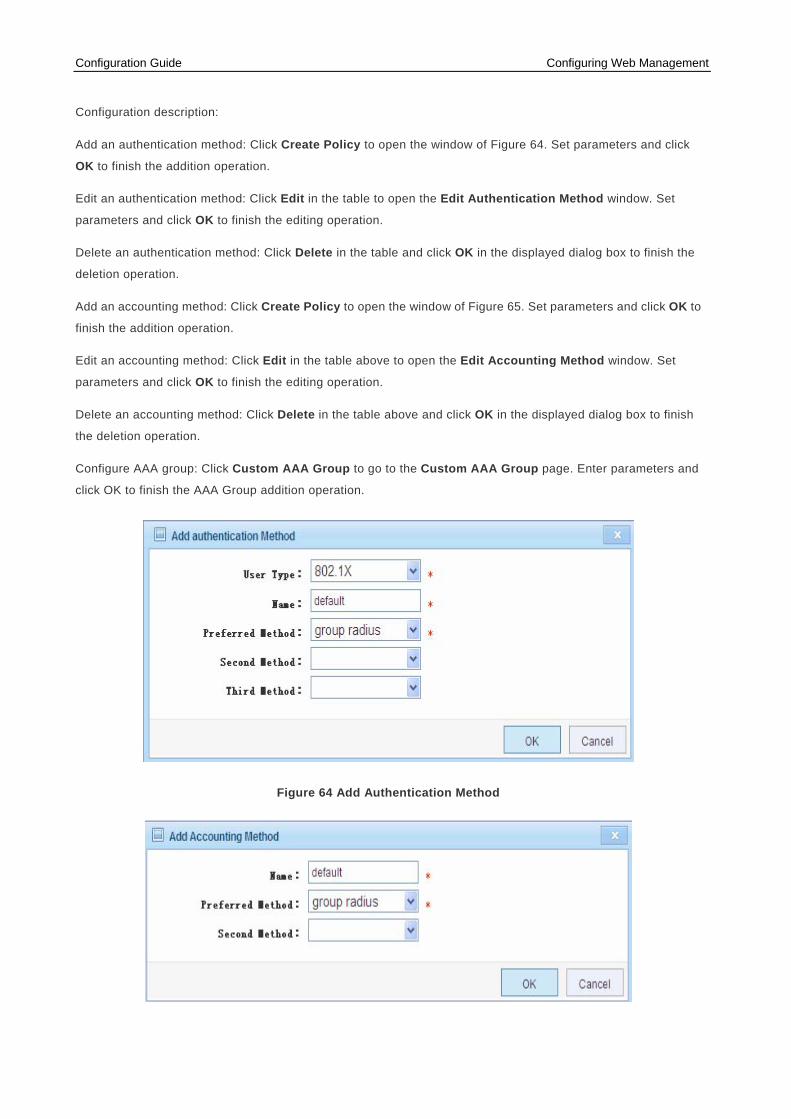
Configuration description:
Add an authentication method: Click Create Policy to open the window of Figure 64. Set parameters and click
OK to finish the addition operation.
Edit an authentication method: Click Edit in the table to open the Edit Authentication Method window. Set
parameters and click OK to finish the editing operation.
Delete an authentication method: Click Delete in the table and click OK in the displayed dialog box to finish the
deletion operation.
Add an accounting method: Click Create Policy to open the window of Figure 65. Set parameters and click OK to
finish the addition operation.
Edit an accounting method: Click Edit in the table above to open the Edit Accounting Method window. Set
parameters and click OK to finish the editing operation.
Delete an accounting method: Click Delete in the table above and click OK in the displayed dialog box to finish
the deletion operation.
Configure AAA group: Click Custom AAA Group to go to the Custom AAA Group page. Enter parameters and
click OK to finish the AAA Group addition operation.
Figure 64 Add Authentication Method

Configuration Guide Configuring Web Management
Figure 65 Add Accounting Method
Figure 109 Custom AAA Group
RADIUS Configuration
Click the Radius menu to enter the following page.
Figure 66 RADIUS Configuration
Configuration description:
Add a RADIUS server: Enter parameters into the form above and click Add to finish the addition operation.
Configuration Guide Configuring Web Management
Delete a RADIUS server: Click Delete in the table above and click OK in the displayed dialog box to finish the
deletion operation.
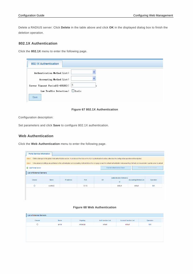
802.1X Authentication
Click the 802.1X menu to enter the following page.
Figure 67 802.1X Authentication
Configuration description:
Set parameters and click Save to configure 802.1X authentication.
Web Authentication
Click the Web Authentication menu to enter the following page.
Figure 68 Web Authentication

Configuration Guide Configuring Web Management
Figure 69 List of Internal Servers
Configuration description:
Add a portal server: Click Add Portal Server to open the window of Figure 70. Set parameters and click OK to
add an external or internal server.
Edit a portal server: Click Edit in the table above to open the Edit Authentication Method window. Set parameters
and click OK to finish the editing operation for an external or internal server.
Delete a portal server: Click Delete in the table above and click OK in the displayed dialog box to finish the
deletion operation.
Figure 70 Add Portal Server
User Authentication Management
Click the User Authentication Management menu to enter the following page.
Figure 71 User Authentication Configuration
Configuration description:

Configuration Guide Configuring Web Management
Import user authentication configuration in batches: Click Batch Import to open the window of Figure 72. Upload
the webauth.txt file in the specified format and click Batch Import to finish the upload operation.
Manually add user authentication configuration: Click Manual configuration to open the window of Figure 73.
Enter parameters and click OK to finish the addition operation.
Edit user authentication configuration: Click Edit in the table above to open the Edit User Info window. Set
parameters and click OK to finish the editing operation.
Delete user authentication configuration: Click Delete in the table above and click OK in the displayed dialog box
to finish the deletion operation.
Figure 72 Import User Information in Batches
Figure 73 Add User Information
Advanced Configuration

Configuration Guide Configuring Web Management
Association Control
Click the Association Control menu to enter the following page, which includes the sub-pages of Package
Configuration and Zone Configuration.

Configuration Guide Configuring Web Management
Terminal Package Configuration
Figure 74 Terminal Package Configuration
Configuration description:
Add a terminal package: Enter a terminal package name and click Add to finish the addition operation.
Edit a terminal package: Click Edit in the table above to open the window of Figure 75.
Delete a terminal package: Click Delete in the table above and click OK in the displayed dialog box to finish the
deletion operation.
Figure 75 Terminal Package Editing

Configuration Guide Configuring Web Management
Associated Control Domain Configuration
Figure 76 Associated Control Domain Configuration
Configuration description:
Add an associated control domain: Enter parameters into the form above and click Add to finish the addition
operation.
Delete an associated control domain: Click Delete in the table above and click OK in the displayed dialog box to
finish the deletion operation.
Balanced Configuration
Figure 77 Balanced Configuration
NTP
Click the NTP menu to enter the following page.
Figure 78 NTP

Configuration Guide Configuring Web Management
Select a type and click Save in the form above to configure NTP.
The Default type indicates that NTP and SNTP are disabled.
Multicast
Click the Multicast menu to enter the following page, which includes the sub-pages of L2 Multicast
Configuration and Multicast-to-Unicast.

Configuration Guide Configuring Web Management
L2 Multicast Configuration
Figure 79 L2 Multicast Configuration
Configuration description:
Configure global L2 multicast: Enable or disable global L2 multicast status and click Save to finish the
configuration.
AC configuration:
Enable IGMP Snooping and click Save to finish the IGMP Snooping configuration.
Click Configure Parameters to open the window of Figure 80. Set parameters and click OK to finish AC
parameter configuration.
Click Configure IGMP Snooping on a Vlan to open the window of Figure 81. Set parameters and click OK to
finish VLAN IGMP Snooping configuration.
Figure 80 AC Configuration Parameter
Figure 81 IGMP Snooping Status of the AC

Configuration Guide Configuring Web Management
Multicast-to-Unicast
Figure 82 Multicast-to-Unicast
Configuration description:
Set parameters and click Save to configure multicast-to-unicast.
System Management
System Settings
Click the System Settings menu to enter the following page, which includes the sub-pages of System Settings,
Log Management, and Password Change.
System Settings
Figure 83 System Settings

Configuration Guide Configuring Web Management
Configuration description:
Basic system information: Enter basic information. If the input information is incorrect, prompt information is
displayed after the input box. The management VLAN is VLAN 1 by default. The displayed information including
the management IP address and the mask will be updated if a different management VLAN is chosen. An input
box followed by "*" is mandatory. The device name, device location, contact person, and contact information are
displayed on the system login page. Enter information in the correct format and click Save. The configuration is
completed after the system prompts "Setting succeeded!"If you want to change the management IP address,
the system prompts you to confirm the change. After the address is changed, the system returns to the login page
for re-login.
System time: The page above displays the current system time. You can manually reset the system time or tick
the Synchronize Time Server option, and click Save. The configuration is completed when the system prompts
"The time has been successfully configured." .
Monitoring Mode: You can select a monitoring mode from the drop-down list box. An AP can detect and counter
rogue APs when it works in hybrid or monitoring mode.
When the management IP address is changed, ensure that the changed IP address is reachable;
otherwise, you cannot log in to Web again.
Log Management
Figure 84 Log Management
Configuration description:
Log configuration: Enter parameters and click Save to finish the configuration.
Historical record: Open the Wlan Diag Enable to monitor the historical records.
The page is automatically refreshed every 30 seconds.

Configuration Guide Configuring Web Management
Password Change
Figure 85 Password Change
Configuration description:
Change the administrator password:
Enter the old password and enter the new password twice. If the input old password is incorrect, the page
prompts "The old password is not correct" in red after the input box. Then enter the right old password and
click Save to finish the change. You can clear passwords entered in the input boxes by clicking Cancel.
Change the Telnet password:
Enter the new password twice and do not need to enter the old password. Except for this difference, the operation
is same as that for changing the administrator password.
After the administrator password is changed, the system returns to the login interface for re-login.
System Upgrade
Click the System Upgrade menu to enter the following page, which includes the sub-page Local Upgrade.
Local Upgrade

Configuration Guide Configuring Web Management
Figure 86 Locate Upgrade
Configuration description:
Click Browse to choose the local upgrade file and click Upgrade to perform local upgrade.
Configuration Management
Click the Configuration Management menu to enter the following page, which includes the sub-pages of Current
Configuration, Backup Configuration, and Restore Factory Settings.

Configuration Guide Configuring Web Management
Current Configuration
Figure 87 Current Configuration
Configuration description:
Current configuration:
The Current Configuration page provides four options: Backup, Import Configuration, Export Configuration,
and View Current Configuration. Choose an option, fill in basic information, and click OK on the bottom left to
finish corresponding configuration. You can view the current configuration.
Backup file list:
You can perform the Restore Backup, Delete Backup, or Save as Backup operation after choosing a file.
Choose a file, tick the intended operation, and click OK on the bottom left to finish the operation.

Configuration Guide Configuring Web Management
Backup Configuration
Figure 88 Backup Configuration
Configuration description:
Choose a configuration file and perform the Restore Backup, Delete Backup, Save as Backup, or Rename
Backup operation.
Restore Factory Settings
Figure 89 Restore Factory Settings
Configuration description:
Click Export Current Configurations to open the Save as dialog box. Choose a storage directory and a file
name and click Save to export the current configuration. Click Restore factory settings, and the system prompts
"Are you sure to delete all configuration? This operation may cause a Web access failure!" Then click OK
to restore factory settings.
Administrator Permissions
Click the Administrator Permissions menu to enter the following page.

Configuration Guide Configuring Web Management
Figure 90 Administrator Permissions
Configuration description:
Add a user: Enter a user name, a password, and an authorized page (by default, all pages are authorized pages
except those with management permissions) and click Add. Then the system prompts "Adding succeeded!" and
the User List displays all STAs.
Diagnostic Tool
Click the Diagnostic Tool menu to enter the following page, which includes the sub-pages of IPv4 Detection,
IPv6 Detection, and Tracert Detection.
IPv4 Detection
Figure 91 IPv4 Detection
Configuration description:
Enter a destination IP address and click Start Detection to display the detection result.

Configuration Guide Configuring Web Management
IPv6 Detection
Figure 92 IPv6 Detection
Configuration description:
Enter a destination IP address and click Start Detection to display the detection result.
Tracert Detection
Figure 93 Tracert Detection
Configuration description:
Enter a destination IP address and click Start Detection to display the detection result.

Configuration Guide Configuring Web Management
SNMP
Click the SNMP menu to enter the following page.
Figure 94 SNMP
Configuration description:
Enter parameters and click Save to finish the SNMP configuration.
Web Console
Click the Web Console menu to enter the following page.
Figure 95 Web Console
Configuration description:
Enter a command and click Send to show the CLI output result.

Configuration Guide Configuring Web Management
System Reboot
Click the System Reboot menu to enter the following page.
Figure 96 System Reboot
Configuration description:
Click Restart and click OK in the displayed dialog box to restart the device.
Configuration Example 1
Networking Requirements
1. An AP serves as a wireless router as well as a fat AP.
2. Establish a small network with a DHCP server configured on the AP.

Configuration Guide Configuring Web Management
Networking Topology
Figure 97 Topology 1
Configuration Tips
1) Configure a Wifi name
2) Configure a Wifi password
3) Configure a management IP Address
4) Configure the DHCP parameters
Configuration Steps
1) Configure a Wifi name (such as zhangsan) shorter than 32 bytes in length.

Configuration Guide Configuring Web Management
Figure 98 SSID Configuration
2) Security Configuration
If there is no requirement for security, you can click Disable. Enabling security configuration is recommended.
WPA2 encryption is selected by default. Please enter a password containing 8-64 characters which can be a
combination of English letters, numbers and special characters.

Configuration Guide Configuring Web Management
Figure 99 Security Configuration
3) Configure a management IP address. By default, it is 192.168.110.1.
4) DHCP Configuration
Figure 101 DHCP Configuration

Configuration Guide Configuring Web Management
Configure an address pool: 192.168.110.0/24
Configure a DNS Server: 192.168.58.110 (Depend on the actual situation)
Click Save to finish the configuration.
Verification
Verify the configuration by performing the following steps:
1) Associate an STA with SSID ruije_wlan_3842 to get IP address 192.168.110.4.
2) Remove the cable connecting the PC and the AP and connect the AP with an extranet port instead.
3) Access http://192.168.110.1 to log in to Web management system again.
If the management IP address is changed, you need to log in to Web management system with a
new IP address.
Configuration Example 2
Networking Requirements
1. An AP serves as a wireless router as well as a fat AP.
2. Establish a small network with a DHCP server configured on an external switch instead of on the AP.

Configuration Guide Configuring Web Management
Networking Topology
Figure 102 Topology 2
Configuration Tips
1) Configure a Wifi name
2) Configure a Wifi password
3) Configure a management IP Address
Configuration Steps
1) Configure a Wifi name (such as zhangsan) shorter than 32 bytes in length.

Configuration Guide Configuring Web Management
Figure 103 SSID Configuration
2) Security Configuration
If there is no requirement for security, you can click Disable. Enabling security configuration is recommended.
WPA2 encryption is selected by default. Please enter a password containing 8-64 characters which can be a
combination of English letters, numbers and special characters.
Figure 104 Security Configuration

Configuration Guide Configuring Web Management
Configure a management IP address. By default, it is
192.168.110.1
Figure 105 Management IP Address
Click Save to finish configuration on the AP.
Then, you need to configure the switch by performing the following steps:
Step1. Enter VLAN configuration mode to configure a VLAN..
Ruijie(config)#int vlan 1
Ruijie(config-if-VLAN 1)#ip add 192.168.110.2 255.255.255.0
Step2. Enter DHCP configuration mode to configure an address pool.
Ruijie(config)#service dhcp
Ruijie(config)#ip dhcp pool sta_dhcp
Ruijie(dhcp-config)#network 192.168.110.0 255.255.255.0
Ruijie(dhcp-config)#dns-server 192.168.58.110
Ruijie(dhcp-config)#default-router 192.168.110.2
Step3.Configure a default route (optional)
Ruijie(config)#ip route 0.0.0.0 0.0.0.0 1.1.1.1
Verification
1. Use the show run command to verify switch configuration.

Configuration Guide Configuring Web Management
Ruijie#show run
Building configuration...
Current configuration : 2374 bytes
!
version RGOS 10.4(3b16) Release(82376)(Fri Sep 7 14:35:58 2012 -R03912)
!
!
!
redundancy
auto-sync time-period 3600
auto-sync standard
switchover timeout 4000
!
!
!
!
!
!
!
!
!
nfpp
!
!
vlan 1
!
!
no service password-encryption
service dhcp
!
!
!
ip dhcp pool aa
network 192.168.110.0 255.255.255.0
dns-server 192.168.58.110
default-router 192.168.110.2
!
!
!
!

Configuration Guide Configuring Web Management
!
!
!
!
!
!
!
!
!
!
!
!
!
!
!
!
!
!
!
!
interface GigabitEthernet 0/1
!
interface GigabitEthernet 0/2
!
interface GigabitEthernet 0/3
!
interface GigabitEthernet 0/4
!
interface GigabitEthernet 0/5
!
interface GigabitEthernet 0/6
!
interface GigabitEthernet 0/7
!
interface GigabitEthernet 0/8
!
interface GigabitEthernet 0/9
!
interface GigabitEthernet 0/10
!
interface GigabitEthernet 0/11
!

Configuration Guide Configuring Web Management
interface GigabitEthernet 0/12
!
interface GigabitEthernet 0/13
!
interface GigabitEthernet 0/14
!
interface GigabitEthernet 0/15
!
interface GigabitEthernet 0/16
!
interface GigabitEthernet 0/17
!
interface GigabitEthernet 0/18
!
interface GigabitEthernet 0/19
!
interface GigabitEthernet 0/20
!
interface GigabitEthernet 0/21
!
interface GigabitEthernet 0/22
!
interface GigabitEthernet 0/23
!
interface GigabitEthernet 0/24
!
interface GigabitEthernet 0/25
!
interface GigabitEthernet 0/26
!
interface GigabitEthernet 0/27
!
interface GigabitEthernet 0/28
!
interface GigabitEthernet 0/29
!
interface GigabitEthernet 0/30
!
interface GigabitEthernet 0/31
!
interface GigabitEthernet 0/32
!

Configuration Guide Configuring Web Management
interface GigabitEthernet 0/33
!
interface GigabitEthernet 0/34
!
interface GigabitEthernet 0/35
!
interface GigabitEthernet 0/36
!
interface GigabitEthernet 0/37
!
interface GigabitEthernet 0/38
!
interface GigabitEthernet 0/39
!
interface GigabitEthernet 0/40
!
interface GigabitEthernet 0/41
!
interface GigabitEthernet 0/42
!
interface GigabitEthernet 0/43
!
interface GigabitEthernet 0/44
!
interface GigabitEthernet 0/45
!
interface GigabitEthernet 0/46
!
interface GigabitEthernet 0/47
!
interface GigabitEthernet 0/48
!
interface VLAN 1
no ip proxy-arp
ip address 192.168.1.2 255.255.255.0
!
!
!
!
!
!
!

Configuration Guide Configuring Web Management
!
!
!
!
!
!
!
!
!
!
!
!
!
ip route 0.0.0.0 0.0.0.0 1.1.1.1
!
!
!
line con 0
line vty 0 4
login
!
!
end
Verify the configuration by performing the following steps:
Step1. Associate an STA with SSID ruije_wlan_3842 to get IP address 192.168.110.2.
Step2. Remove the cable connecting the PC and the AP and connect the AP with an extranet port instead.
If the management IP address is changed, you need to log in to Web management system with a
new IP address.