rg-switch web-based configuration guide - ruijie.cz
TRANSCRIPT

RG-Switch Web-Based Configuration Guide

Copyright Statement
Ruijie Networks©2017
Ruijie Networks reserves all copyrights of this document. Any reproduction, excerption, backup, modification,
transmission, translation or commercial use of this document or any portion of this document, in any form or by any means,
without the prior written consent of Ruijie Networks is prohibited.
Exemption Statement
This document is provided “as is”. The contents of this document are subject to change without any notice. Please obtain
the latest information through the Ruijie Networks website. Ruijie Networks endeavors to ensure content accuracy and will
not shoulder any responsibility for losses and damages caused due to content omissions, inaccuracies or errors.

1-1
Preface
Thank you for using our products.
Audience
This manual is intended for:
Network engineers
Technical support and servicing engineers
Network administrators
Obtaining Technical
Assistance
Ruijie Networks Website: http://www.ruijienetworks.com/
Service Email: [email protected]
Technical Support: http://www.ruijienetworks.com/service.aspx
Technical Support Hotline: +86-4008-111-000
Related Documents
Documents Description
Command Reference Describes the related configuration commands, including command modes,
parameter descriptions, usage guides, and related examples.
Hardware Installation and Reference
Guide
Describes the functional and physical features and provides the device
installation steps, hardware troubleshooting, module technical specifications,
and specifications and usage guidelines for cables and connectors.
Conventions
This manual uses the following conventions:
Convention Description
boldface font Commands, command options, and keywords are in boldface.

1-2
italic font Arguments for which you supply values are in italics.
[ ] Elements in square brackets are optional.
{ x | y | z } Alternative keywords are grouped in braces and separated by vertical bars.
[ x | y | z ] Optional alternative keywords are grouped in brackets and separated by
vertical bars.
Symbols
Means reader take note. Notes contain helpful suggestions or references.
Means reader be careful. In this situation, you might do something that could result in equipment damage or loss of
data.

Configuration Guide Web-Based Configuration
1-1
1 Web-Based Configuration
1.1 Overview
A user accesses and employs the Web-based management system for a switch using a web browser like IE. Web-based
management involves two parts: Web server and Web client. A web server is integrated into a device to receive and process
requests sent from a client (for example, to read a web file or execute a command request) and returns the processing
results. Generally, a Web client refers to a web browser like IE.
Currently, this file is applicable to only switches.
1.2 Application
Application Description
Web-based Management After finishing relevant configuration, a user can access the web-based management
system through a browser.
1.2.1 Web-based Management
Scenario
As shown in the following figure, a user can access an access or aggregation switch with a browser on a PC to manage and
configure the device.
Figure 1-1

Configuration Guide Web-Based Configuration
1-2
Note A user can access the Web-based management system of the switch in the red rectangle if the switch can be
pinged from the PC.
Function Deployment
Configuration Environment Requirements
Requirements for Client
An administrator logs in to the Web-based management system using the web browser on a client to manage the switch.
Generally, a client refers to a PC. It may also be other mobile terminal devices like a laptop.
Browser: IE7.0, IE8.0, IE9.0, IE10.0, IE11.0, Google chrome, Firefox, and some IE kernel-based browsers (for example,
360 security browser) are all supported. Exceptions such as messy code and format errors may occur when other
browsers are used.
Resolution: It is recommended that the resolution be set to 1024*768, 1280*1024, or 1920*1080. Exceptions such as
font alignment error and format error may occur after selecting other resolutions.
Server Requirements
The Web service must be enabled for the switch.
Login authentication information for Web-based management must be configured for the switch.
A management IP address must be configured for the switch.
For the detailed configuration of the switch on the command line interface (CLI), see Configuring Web Server.
Web configuration and CLI configuration can be performed synchronously. It is recommended that the write command
be executed after CLI configuration is completed. If any web page is opened, please refresh this page to synchronize
web and CLI configuration.
Login
Type http://X.X.X.X (management IP address) in the address bar of a browser and press Enter to access the login page, as
shown in the following figure.
Figure 1-2 Login Page

Configuration Guide Web-Based Configuration
1-3
After typing the username and password, click Login. The following table lists the default username and password.
Default
Username/Password
Permission Description
admin / admin Super administrator possessing all permissions.
The default username and password are not displayed by running the show running-config command.
After passing authentication, the home page of the web-based management platform is displayed, as shown in the following
figure.
Figure 1-3 Home Page

Configuration Guide Web-Based Configuration
1-4
For details on the web page, see Web Management System below.
1.3 Web Management System
Basic Concepts
Various Icons and Buttons on the GUI
Icon/Button Note
Edit button. Click this icon to edit the currently selected item.
Delete button.
Status icon.
Port available for selection. After you click or select this port, it becomes a selected port.
Port not available for selection.
Selected port.
Aggregate port. The number in the port indicates the aggregate port number.
Trunk port. This port is displayed on the panel on the VLAN Management/VLAN Settings page.

Configuration Guide Web-Based Configuration
1-5
Save button. Click this button to submit and save the input information.
Add setting.
Delete setting.
Batch processing operations on panel ports. These icons are located on the lower right of the
panel. These icons are available only on the panel where selecting multiple ports is allowed.
If this mark is displayed behind a text box, the item corresponding to the text box is mandatory.
Note.
Warning.
System Operations
1) Standalone Device Panel
2) VSU Device Panel
Panel operations
Click to select a port or move the cursor to select multiple ports on the panel to change available port(s) into selected port(s).
To add a setting on a selected port, for example, add port description, configure port mirroring, and configure port rate limiting.
Selected ports are arranged in the boxes in the lower section of the port panel by slots.

Configuration Guide Web-Based Configuration
1-6
1) Selected port on standalone device
2) Selected port on a VSU device
Features
The following table describes the functions in the secondary menu on the left of the Web page.
Feature Description
Home Page For viewing port information and device configuration.
VLAN Used to set the VLAN and Trunk ports.
Quick Configuration Used for quickly performing VLAN configuration or other configurations.
Port Used to perform basic settings on a port and configure port aggregation, port mirroring, and port
rate limiting.
Restart For restarting the device.
MAC Address For configuring the static address and filtering address.
'Routing Used to configure the route.
STP Used to configure basic STP information, STP ports and RLDP.
IGMP Snooping Used to configure IGMP Snooping.
DHCP Relay Used to configure DHCP relay.
Authentication For configuring Eportal authentication and enabling advanced settings.
DHCP Snooping Used to configure DHCP Snooping.
Anti-ARP-Attack Used to perform anti-ARP-spoofing settings, ARP check settings, DAI settings, and ARP entry
settings.
IP Source Guard Used to perform port settings and user binding.
Port Security Used to perform basic settings and security binding.
NFPP Used to view the content related to NFPP anti-attack.
Storm Control Used to perform storm control.
Port Protection Used to configure port protection.

Configuration Guide Web-Based Configuration
1-7
DHCP Used to perform DHCP settings and static address allocation and access the client list.
ACL Used to set the ACL list and ACL time and apply ACL.
QoS Used to perform classification setting, policy setting, and stream setting.
System Settings Used to set the system time, modify passwords, restart the system, restore to default factory
settings, configure enhanced functions, and set the SNMP and DNS.
System Upgrade Used to perform local upgrade and online upgrade.
Administrator Permissions Used to set the administrator permissions.
System Logging Used to configure the log server and view system logs.
Network Detection Used to configure ping, Traceroute (tracert.exe) and cable detection.
1.3.1 Quick Settings
Figure 1-4 Quick Settings

Configuration Guide Web-Based Configuration
1-8
Select the management port mode, configure the VLAN ID, IP address, subnet mask, default gateway, and DNS server, and
click Save. If the message ”Configuration succeeded.” is displayed, the operation is successful.
1.3.2 Favorites
You can access secondary menus through the primary menu Favorites, including Home page, VLAN, Port and Restart.
1.3.2.1 Home Page
Device configuration, basic port information, and port statistics are displayed on the home page.
The following figure shows the home page.
Figure 1-5 Home Page
1.3.2.2 VLAN
A Virtual Local Area Network (VLAN) is a logical network created based on a physical network. A VLAN can be categorized
into Layer-2 networks of the OSI model.
A VLAN has the same properties as a common LAN, except for physical location limitation. Unicast, broadcast and multicast
frames of Layer 2 are forwarded and transmitted within a VLAN, keeping traffic segregated.
We may define a port as a member of a VLAN, and all terminals connected to this port are parts of a virtual network that
supports multiple VLANs. You do not need to adjust the network physically when adding, removing and modifying users.
Communication among VLANs is realized through Layer-3 devices, as shown in the following figure.

Configuration Guide Web-Based Configuration
1-9
The VLANs supported by Ruijie products comply with the IEEE802.1Q standard. A maximum of 4094 VLANs (VLAN ID
1-4094) are supported, among which VLAN 1 cannot be deleted.
A trunk port can belong to multiple VLANs that receives and sends frames belonging to multiple VLANs. Generally, it is used
to connect devices or computers.
Two tab pages are available on the VLAN page: VLAN Settings and Trunk Port.
VLAN Settings
The following figure shows the VLAN Settings page.
Figure 1-6 VLAN Settings
Adding VLAN
To add a VLAN, you must input the VLAN ID and input other information as required. Afterwards, click Save. The newly
added VLAN is displayed in the VLAN list after the ”Add succeeded.” message is displayed.
Editing a VLAN

Configuration Guide Web-Based Configuration
1-10
After clicking Edit in the Action column, information from the corresponding VLAN is displayed on the page. After editing the
information, click Save. The ”Edit succeeded.” message is then displayed.
Deleting a VLAN
1) Select multiple VLANs from the VLAN list and click Delete Selected VLAN to delete the VLANs in batches.
2) Click Delete in the Action column, the message, “Are you sure you want to delete the VLAN?” is then displayed.
After confirming the operation, the message, “Delete succeeded.” is displayed. VLAN 1 is the default VLAN and cannot be
deleted.
VLAN 1 is the default management VLAN. This VLAN can only be modified and cannot be deleted. Before changing the
IP address of VLAN 1, ensure that the new IP address is reachable. After the change is successful, the web page
automatically jumps to the login page and the user must log in again. If the web page does not jump to the login page
and a "page not found" message is displayed, it is possible that the IP address is not reachable. In this case, check the
network connection.
Trunk Port
The following figure shows the Trunk Port page.
Figure 1-7 Trunk Port
Adding a trunk port

Configuration Guide Web-Based Configuration
1-11
Select a panel port, specify Native VLAN and Allowed VLAN (for example, 3-5, 8, and 10), and click Save. The ”Configuration
succeeded.” message is displayed. In this case, the newly added trunk port is displayed in the trunk port list.
Editing a trunk port
Click a certain trunk port in the trunk port list, and the information of this trunk port is displayed on the page. After editing the
information, click Edit. The ”Configuration succeeded.” message is displayed.
Deleting trunk port
After moving the cursor to a specific trunk port in the trunk port list click Delete. The message, ”Are you sure you want to
delete the trunk port?” is then displayed.
After confirming the operation, a ”Delete succeeded.” message is displayed.
Deleting trunk ports in batches
After selecting the trunk ports to be deleted (in the trunk port list) click Batch Del. The message, ”Are you sure you want to
delete the trunk ports?” is displayed.
After confirming the operation, a ”Delete succeeded.” message is displayed.
1.3.2.3 Port
A port is a physical entity that is used for connections on the network devices.
Speed
Generally, the speed of an Ethernet physical port is determined through negotiation with the peer device. The negotiated
speed can be any speed within the interface capability. You can also configure any speed within the interface capability for
the Ethernet physical port on the Web page.
When you configure the speed of an AP port, the configuration takes effect on all of its member ports. (All these member
ports are Ethernet physical ports.)
Interface Name
You can configure the name of an interface based on the purpose of the interface. For example, if you want to assign
GigabitEthernet 1/1 for exclusive use by user A, you can describe the interface as "Port for User A."
Administrative Status
You can configure the administrative status of an interface to disable the interface as required. If the interface is disabled, no
frame will be received or sent on this interface, and the interface will loss all its functions. You can enable a disabled interface
by configuring the administrative status of the interface. Two types of interface administrative status are defined: Up and
Down. The administrative status of an interface is Down when the interface is disabled, and Up when the interface is
enabled.
Aggregated Port
An aggregated port (AP) is used to bundle multiple physical links into one logical link to increase the link bandwidth and
improve connection reliability. An AP port supports load balancing, namely, distributes load evenly among member links.

Configuration Guide Web-Based Configuration
1-12
Besides, an AP port realizes link backup. When a member link of the AP port is disconnected, the load carried by the link is
automatically allocated to other functional member links. A member link does not forward broadcast or multicast packets to
other member links.
Duplex Mode
The duplex mode of an Ethernet physical port or AP port can be configured as follows:
Set the duplex mode of the interface to full-duplex so that the interface can receive packets while sending packets.
Set the duplex mode of the interface to half-duplex so that the interface can receive or send packets at a time.
Set the duplex mode of the interface to auto-negotiation so that the duplex mode of the interface is determined through
auto negotiation between the local interface and peer interface.
Load Balancing
AP ports segregate packet flows by using load balancing algorithms based on packet features, such as the source and
destination MAC addresses, source and destination IP addresses, and source and destination port numbers. The packet flow
with the consistent feature is transmitted by one member link, and different packet flows are evenly distributed to member
links. For example, in source MAC address-based load balancing, packets are distributed to the member links based on the
source MAC addresses of the packets. Packets with different source MAC addresses are evenly distributed to member links.
Packets with the identical source MAC address are forwarded by one member link.
Currently, there are several AP load balancing modes as follows:
Source MAC address or destination MAC address
Source MAC address + destination MAC address
Source IP address or destination IP address
Source IP address + destination IP address
Different products may support different load balancing algorithms.
SPAN
The Switched Port Analyzer (SPAN) is to copy packets of a specified port to another switch port that is connected to a
network monitoring device, so as to achieve network monitoring and troubleshooting.
All input and output packets of a source port can be monitored through SPAN. For example, as shown in the following figure,
all packets on Port 5 are mapped to Port 10, and the network analyzer connected to Port 10 receives all packets that pass
through Port 5.
Figure 1-8 SPAN Configuration Instance

Configuration Guide Web-Based Configuration
1-13
The SPAN function is mainly applied in network monitoring and troubleshooting scenarios, to monitor network information
and rectify network faults.
Source Port
A source port is called a monitored port. In a SPAN session, data streams of the source port are monitored for network
analysis and troubleshooting. In a single SPAN session, users can monitor the input, output, and bidirectional data streams,
and the number of source ports is not restricted.
A source port has the following features:
A source port can be a switched port, routed port, or AP.
A source port cannot be used as a destination port simultaneously.
A source port and a destination port can belong to the same VLAN or different VLANs.
Destination Port
A SPAN session has one destination port (called a monitoring port) for receiving packets copied from a source port.
A destination port has the following features:
A destination port can be a switched port, routed port, or AP.
A destination port cannot be used as a source port simultaneously.
The Port menu allows you to perform basic settings on a port and configure port aggregation, port mirroring, and port rate
limiting.
Basic Settings
Figure 1-9 Basic Settings

Configuration Guide Web-Based Configuration
1-14
Basic port settings
Select the port for configuring, and then select Status, Speed, and Working Mode. “Keep” indicates that the original
configuration is retained. During batch setting, you can select “Keep” to implement batch setting for one or two items.
Editing port
After you click Edit in the Action column, the information of the corresponding port is displayed on the page. After editing the
information, click Save. A ”Configuration succeeded.” message is displayed.
Aggregate Port
The following figure shows the Aggregate port page.
Figure1-10 Aggregate Port

Configuration Guide Web-Based Configuration
1-15
Adding aggregate port
After specifying Aggregate Port ID and selecting the member port, click Add. A “Configuration succeeded.” message is
displayed. The newly added aggregate port is displayed on the panel.
Editing an aggregate port
The aggregate ports displayed on the panel are unavailable ports. To edit them, you can click a certain aggregate port in the
aggregate port list. Afterwards, the member port becomes a selected port. Click this port to deselect it. Afterwards, you can
click Edit to modify the aggregate port.
Deleting an aggregate port
After you move the cursor to an aggregate port in the aggregate port list and click Delete, the message, ”Are you sure you
want to delete the aggregate port?” is displayed. After confirming the operation, the aggregate port becomes an available
port on the panel.
Deleting aggregate ports in batches
After you select the aggregate ports to be deleted in the aggregate port list and click Batch Del, an “Are you sure you want to
delete the aggregate port?” message is displayed. After you confirm the operation, these aggregate ports become available
ports on the panel.

Configuration Guide Web-Based Configuration
1-16
The port enabled with ARP check, anti-ARP-spoofing, or MAC VLAN and the monitoring port in port mirroring cannot be
added to the aggregate port. They are displayed as unavailable ports on the panel. After the cursor is moved to an
unavailable port, a message is displayed to indicate that a function has been enabled for the port, so the port is
unavailable.
Port Mirroring
The following figure shows the Port Mirroring page.
Figure 1-11 Port Mirroring
Initially, the Port Mirroring page is in an edit state because only one mirroring port is allowed to be set on the Web. Two
panels are available on the page. The port selected from the upper panel will serve as a source port (mirrored port, multiple
mirrored ports are allowed). Only one port can be selected from the lower panel to serve as the destination port (mirroring
port). After selecting or modifying a port on the panel, click Save. The “Configuration succeeded.” message is displayed.
The current port mirroring status is displayed on the panel, which is in edit state. If you do not want to edit a port after
modifying it, click Refresh to make the panel display the current status of port mirroring.

Configuration Guide Web-Based Configuration
1-17
The member port of the aggregate port cannot serve as a destination or source port. A port cannot serve as a
destination port and source port at the same time.
Rate Limiting
The following figure shows the Rate Limiting page.
Figure 1-12 Rate Limiting
Adding a rate limiting port
To add a rate limiting port, you must specify at least the input rate limit or output rate limit, and click Save. The new rate
limiting port is displayed in the rate limiting port list after a “Configuration succeeded.” message is displayed.
Editing rate limiting port
After clicking Edit in the Action column, the information of the corresponding rate limiting port is displayed on the page. After
editing the information, click Save. The “Configuration succeeded.” message is displayed.
Deleting rate limiting port
1) Select multiple ports from the rate limiting port list and click Batch Delete to delete the ports in batches.
2) After clicking Delete in the Action column, the message, “Are you sure you want to delete the port configuration?” is
displayed. After confirming the operation, a “Delete succeeded.” message is displayed.
1.3.2.4 Restart
The following figure shows the Restart page.
Figure 1-13 Restart
After clicking Restart, the message, “Are you sure you want to restart the device?” is displayed.

Configuration Guide Web-Based Configuration
1-18
After confirming the operation, the device is restarted. Restart takes several minutes. Please be patient. The page is
refreshed automatically after the device is restarted.
1.3.3 Network
Secondary menus can be accessed through the primary menu Network, including MAC Address, Routing, STP, IGMP
Snooping, Authentication and DHCP Relay.
1.3.3.1 MAC Address
A media access control address (MAC address) of a computer is a unique identifier assigned to network interfaces for
communications at the data link layer of a network segment. MAC addresses are used as a network address for most IEEE
802 network technologies, including Ethernet and Wi-Fi. Logically, MAC addresses are used in the media access control
protocol sub-layer of the OSI reference model.
A static address is a manually configured MAC address. A static address is the same as a dynamic address in terms of
function. However, you can only manually add and delete a static address rather than learn and age out a static address. A
static address is stored in the configuration file and will not be lost even if the device restarts.
By configuring the static address manually, you can bind the MAC address for the network device with the interface in the
MAC address table.
A filtering address is a manually configured MAC address when the device receives the packets from a filtering address, it
will directly discard them. You can only manually add and delete a filtering address rather than age it out. A filtering address
is stored in the configuration file and will not be lost even if the device restarts.
If you want the device to filter some invalid users, you can specify their source MAC addresses as filtering addresses.
Consequently, these invalid users cannot communicate with outside through the device.
Two tab pages are available on the MAC Address page: Static Address Settings and Filtering Address Settings.
Static Address Settings
Figure 1-14 Static Address Settings
Adding Static Addresses

Configuration Guide Web-Based Configuration
1-19
To add a static address, input the MAC address, VLAN ID and select a port, and then click Save. The newly added static
address is displayed in the address list after the ”Configuration succeeded.” message is displayed.
Deleting Static Address
1) You can select multiple static addresses and click Delete Static Address to delete the addresses in batches.
2) After clicking Delete in the Action column, the message, “Are you sure you want to delete the static address?” is displayed.
After confirming the operation, a ”Delete succeeded.” message is displayed.
Filtering Address Settings
Figure 1-15 Filtering Address Settings
Adding Filtering Address
To add a filtering address, input the MAC address and VLAN ID, and then click Save. The newly added filtering address is
displayed in the address list after a ”Configuration succeeded.” message is displayed.
Editing Filtering Address
After clicking Edit in the Action column, the information of the corresponding filtering address is displayed on the page. After
editing the information, click Save, the ”Configuration succeeded.” message is then displayed.
Deleting Filtering Address
1) You can select multiple filtering addresses and click Delete Filter Address to batch delete addresses.
2) After you click Delete in the Action column, an “Are you sure you want to delete the filter address?” message is displayed.
After you confirm the operation, the ”Delete succeeded.” message is displayed.

Configuration Guide Web-Based Configuration
1-20
1.3.3.2 Routing
Routing is the process of selecting a path for traffic in a network, or between or across multiple networks.
Static routing is a form of routing that occurs when a router uses a manually-configured routing entry. In many cases, static
routes are manually configured by a network administrator by adding in entries into a routing table, though this may not
always be the case.
Default route is a setting on a computer that defines the packet forwarding rule to use when no specific route can be
determined for a given Internet Protocol (IP) destination address. All packets for destinations not established in the routing
table are sent via the default route.
The Route Settings page allows you to manage routes.
The following figure shows the Route Settings page.
Figure 1-16 Route Settings
Adding static routes
To add a static route, IP Type, Destination Subnet, Subnet Mask, and Next Hop Address must be set. Afterwards, click Save.
The newly added route is displayed in the route list after a “Save succeeded.” message is displayed.
Editing routes
After clicking Edit in the Action column, information for the corresponding route is displayed on the page. After editing the
information, click Save. The message, ”Save succeeded.” is displayed.
Deleting routes
1) Multiple routes can be selected from the route list. Click Delete Selected Route to batch delete routes.
2) After clicking Delete in the Action column, the message, “Are you sure you want to delete the route?” is displayed.
After confirming the operation, the message, ”Delete succeeded.” is displayed.
Adding default routes
To add a default route, you must set IP Type and Next Hop Address. Afterwards, click Save. The newly added route is
displayed in the route list after the ”Save succeeded.” message is displayed.

Configuration Guide Web-Based Configuration
1-21
1.3.3.3 STP
The Spanning Tree Protocol (STP) is a network protocol that builds a logical loop-free topology for Ethernet networks. The
basic function of STP is to prevent bridge loops and the broadcast radiation that results from them. Spanning tree also allows
a network design to include spare (redundant) links to provide automatic backup paths, if an active link fails. This is done
without the danger of bridge loops, or the need for manual enabling or disabling of these backup links.
The Rapid Link Detection Protocol (RLDP) achieves rapid detection of unidirectional link failures, directional forwarding
failures and downlink loop failures of an Ethernet. When a failure is found, relevant ports will be closed automatically
according to failure treatment configuration or the user will be notified to manually close the ports to avoid wrong flow
forwarding or an Ethernet layer-2 loop.
The STP Global Settings page enables setting the global parameters and STP ports.
STP Global Settings
Figure 1-17 STP Global Settings
STP global parameters can be configured. When MSTP is selected from the STP Mode drop-down list, you can configure the
MST instance.
Adding instances

Configuration Guide Web-Based Configuration
1-22
To add an instance, input the instance value and VLAN range and input other information as required. Afterwards, click Save.
The newly added instance is displayed in the instance list after a “Configuration succeeded.” message is displayed.
Editing instances
After clicking Edit in the Action column, the information of the corresponding instance is displayed on the page. After editing
the information, click Save. A”Configuration succeeded” message is displayed.
Deleting instances
1) Multiple instances can be selected from the instance list. Click Delete Selected Instance to batch delete instances.
2) After clicking Delete in the Action column, the message, ”Are you sure you want to delete the instance?” is displayed.
After confirming the operation, he ”Delete succeeded.” message is displayed. Instance 0 is the default instance and cannot
be deleted.
STP Port Settings
Figure 1-18 STP Port Settings
Batch setting
Specify Protection Mode, Port Fast, BPDU Guard, Connection Mode, and Port Priority. Then select ports for batch setting.
Editing STP ports
After clicking Edit in the Action column, the information of the corresponding port is displayed on the page. After editing the
information, click Save. The message, “Configuration succeeded” is displayed.
RLDP Settings
Figure 1-19 RLDP Settings

Configuration Guide Web-Based Configuration
1-23
1. Global Configuration
Enable/Disable RLDP by turning on/off the switch. After setting detection interval and count, click Save. The message,
"Configuration succeeded" is displayed.
2. Port Configuration
Adding RLDP Ports
Select detection mode, troubleshooting mode and port. Afterwards, click Save. The newly added RLDP port is displayed in
the RLDP port list after the message, “Configuration succeeded.” is displayed.
Editing RLDP Ports
After clicking Edit in the Action column, the information of the corresponding RLDP port is displayed on the page. After
editing the information, click Save. An “Edit succeeded.” message is displayed.
Deleting RLDP Port
1) Multiple RLDP ports can be selected from the RLDP port list. Click Delete Selected Port to batch delete RLDP ports.
2) After clicking Delete in the Action column, the ”Are you sure you want to delete the item?” message is displayed.
After confirming the operation, the ”Delete succeeded.” message is displayed.

Configuration Guide Web-Based Configuration
1-24
1.3.3.4 IGMP Snooping
Internet Group Management Protocol (IGMP) snooping is a mechanism of listening to IP multicast. It is used to manage and
control the forwarding of IP multicast traffic within VLANs, realizing Layer-2 multicasting.
The IGMP snooping examines IGMP protocol messages within a VLAN to discover which interfaces are connected to hosts
or other devices interested in receiving this traffic. Using the interface information, IGMP snooping can reduce bandwidth
consumption in a multi-access LAN environment to avoid flooding the entire VLAN. The IGMP snooping feature tracks which
ports are attached to multicast-capable routers to help it manage the forwarding of IGMP membership reports.
The following figure shows the IGMP Snooping Settings page.
Figure 1-20 IGMP Snooping Settings
Adding profiles
To add a profile, you must input the profile identifier and multicast address range. Other information can be inputted as
required. Afterwards, click Save. The newly added profile is displayed in the profile list after the ”Add succeeded” message is
displayed.
Editing profiles
After clicking Edit in the Action column, information for the corresponding profile is displayed on the page. After editing the
information, click Save. The message, ”Edit succeeded.” message is then displayed.
Deleting profiles
1) Multiple profiles from the profile list can be selected. Click Delete Selected Profile to batch delete the profiles.
2) After clicking Delete in the Action column the message, “Are you sure you want to delete the profile?” is displayed.
After confirming the operation, the ”Delete succeeded.” message is displayed.
1.3.3.5 DHCP Relay
Based on the RFC 2131, DHCP server assigns IP addresses to clients and manages these IP addresses.
DHCP Client enables a device to automatically obtain an IP address and configurations from a DHCP server.
When a DHCP client and a DHCP server are not in a same subnet, they need a DHCP relay to forward DHCP request and
reply packets.

Configuration Guide Web-Based Configuration
1-25
A DHCP relay agent is any host that forwards DHCP packets between clients and servers. Relay agents are used to forward
requests and replies between clients and servers when they are not on the same physical subnet. Relay agent forwarding is
distinct from the normal forwarding of an IP router, where IP datagrams are switched between networks somewhat
transparently. By contrast, relay agents receive DHCP messages and then generate a new DHCP message to send on
another interface.
The following figure shows the DHCP Relay Settings page.
Figure 1-21 DHCP Relay Settings
When DHCP Relay is enabled, multiple DHCP server addresses can be configured.
1.3.3.6 Authentication
The Authentication page allows setting of Eportalv2 and Advanced.
Eportalv2
The following figure shows the Eportalv2 page.
Figure 1-22 Eportalv2

Configuration Guide Web-Based Configuration
1-26
Enter the server IP address and redirection URL and click Save. The message, "Configuration succeeded." is displayed.
Advanced
The following figure shows the Advanced page.
Figure 1-23 Advanced Settings

Configuration Guide Web-Based Configuration
1-27
Multiple authentication-exempted network resources and user IP addresses can be set. Click Save, and the message,
"Configuration succeeded." is then displayed
1.3.4 Security
Secondary menus are accessed through the primary Security menu that includes DHCP Snooping, Anti-ARP-Attack, IP
Source Guard, Port Security, NFPP, and Storm Control.
1.3.4.1 DHCP Snooping
DHCP Snooping: DHCP Snooping snoops DHCP interactive packets between clients and servers to record and monitor
users' IP addresses and filter out illegal DHCP packets, including client request packets and server response packets. The
legal user database generated from DHCP Snooping records may serve security applications like IP Source Guard.

Configuration Guide Web-Based Configuration
1-28
Request packets are sent from a DHCP client to a DHCP server, including DHCP-DISCOVER packets, DHCP-REQUEST
packets, DHCP-DECLINE packets, DHCP-RELEASE packets and DHCP-INFORM packets.
Response packets are sent from a DHCP server to a DHCP client, including DHCP-OFFER packets, DHCP-ACK packets
and DHCP-NAK packets.
IP address request interaction is complete via broadcast. Therefore, illegal DHCP services will influence normal clients'
acquisition of IP addresses and lead to service spoofing and stealing. To prevent illegal DHCP services, DHCP Snooping
ports are divided into two types: trusted ports and untrusted ports. The access devices only transmit DHCP response packets
received on trusted ports, while such packets from untrusted ports are discarded. In this way, we may configure the ports
connected to a legal DHCP Server as trusted and the other ports as untrusted to shield illegal DHCP Servers.
On switches, all switching ports or layer-2 aggregate ports are defaulted as untrusted, while trusted ports can be specified.
The following figure shows the DHCP Snooping Settings page.
Figure 1-24 DHCP Snooping Settings
The port connected to the DHCP server must be configured as a DHCP trusted port. The DHCP server connected to a
non-trusted port cannot work properly. If the selected port on the panel is a DHCP trusted port, a port can be directly selected
on the panel, then click the Save button.
1.3.4.2 Anti-ARP-Attack
ARP is a TCP/IP protocol that obtains physical addresses according to IP addresses. Its function is as follows: The host
broadcasts ARP requests to all hosts on the network and receives the returned packets to determine physical addresses of
the target IP addresses, and saves the IP addresses and hardware addresses in the local ARP cache, which can be directly

Configuration Guide Web-Based Configuration
1-29
queried in response to future requests. On the same network, all the hosts using the ARP are considered as mutually trustful
to each other. Each host on the network can independently send ARP response packets; the other hosts receive the
response packets and record them in the local ARP cache without detecting their authenticity. In this way, attackers can send
forged ARP response packets to target hosts so that the messages sent from these hosts cannot reach the proper host or
reach a wrong host, thereby causing ARP spoofing.
The Address Resolution Protocol (ARP) packet check filters all ARP packets under ports (including wired layer-2 switching
ports, layer-2 aggregate ports (APs), and layer-2 encapsulation sub-interfaces, as well as WLAN interfaces) and discards
illegal ARP packets, so as to effectively prevent ARP deception via networks and to promote network stability. On devices
supporting ARP check, illegal ARP packets in networks will be ignored according to the legal user information (IP-based or
IP-MAC based) generated by security application modules such as IP Source Guard.
Dynamic Address Resolution Protocol (ARP) inspection (DAI) checks the validity of received ARP packets. Invalid ARP
packets will be discarded.
ARP packet check is performed according to the trust status of ports. DAI considers packets received from trusted ports as
valid without checking their validity, but it checks the validity of packets received from untrusted ports.
For a typical network configuration, you should configure Layer-2 ports connected to network devices as trusted ports, and
configure Layer-2 ports connected to hosts as untrusted ports.
Network communication may be affected if a Layer-2 port connected to a network device is configured as an untrusted
port.
The Anti-ARP-attack page enables anti-ARP-spoofing settings, ARP check settings, DAI settings, and ARP entry settings.
Anti-ARP-Spoofing
Figure 1-25 Anti-ARP-Spoofing
Adding filtering port
To add a filtering port, first input the IP address. Afterwards, click Save. The newly added filtering port is displayed in the
filtering port list after the ”Add succeeded.” message is displayed.
Editing filtering port
After you click Edit in the Action column, the information of the corresponding filtering port is displayed on the page. After
editing the information, click Save. An “Edit succeeded” message is displayed.

Configuration Guide Web-Based Configuration
1-30
Deleting filtering port
1) You can select multiple filtering ports from the filtering port list and click Delete Selected Port to batch delete the filtering
ports.
2) Click Delete in the Action column, and the “Are you sure you want to delete the port?” message is displayed.
After confirming the operation, the ”Delete succeeded.” message is displayed.
ARP Check
Figure 1-26 ARP Check
The selected port on the panel is enabled with ARP Check.
The selected port on the panel is enabled with ARP Check and in edit state. If you do not want to edit a port after
modifying it, click Display ARP Check Port for the panel display to show the current status of the ARP check.
ARP check cannot be enabled on a DHCP Snooping trusted port.
DAI Settings
Figure 1-27 DAI Settings

Configuration Guide Web-Based Configuration
1-31
1. VLAN DAI settings
Click the add icon to add a VLAN enabled with the DAI function.
2. DAI trusted port
The selected port on the panel is enabled with the DAI function.
The selected port on the panel is enabled with the DAI function and is in edit state. If you do not want to edit a port after
modifying it, click Display Trusted Port for the panel display to the current status of the DAI trusted port.
ARP check cannot be enabled on a DHCP Snooping trusted port.
ARP Entries
Figure 1-28 ARP Entries

Configuration Guide Web-Based Configuration
1-32
Remove Static Binding
1) Select multiple dynamic binding from the ARP entry list to configure them as static binding in batches.
2) Click the Dynamic Binding>>Static Binding icon in the Action column. The "Configuration succeeded.” message is
displayed.
Remove Static Binding
1) You can select and remove multiple static bindings from the ARP entry list.
2) Click the Remove static Binding icon in the Action column. The ”Configuration succeeded.” message is displayed.
Manual Binding
To add a static binding, it is necessary to configure the IP and MAC Addresses. Afterwards, click Save. The newly added
static binding is displayed in the ARP entry list after the ”Configuration succeeded.” message is displayed.
1.3.4.3 IP Source Guard
The IP Source Guard function realizes hardware-based IP packet filtering to ensure that only the users having their
information in the binding database can access networks normally, preventing users from forging IP packets.
Usually IP Source Guard needs to work with DHCP Snooping. Therefore, DHCP Snooping should also be enabled.
DHCP Snooping can be enabled at any time on Ruijie devices, either before or after IP Source Guard is enabled.
When IP Source Guard is enabled, the source addresses of packets passing through a port will be checked. The port can be
a wired switching port, a layer-2 aggregate port (AP), or a layer-2 encapsulation sub-interface, or a WLAN interface. Such
packets will pass the port only when the source address fields of the packets match the set of the address binding records
generated by DHCP Snooping, or the static configuration set by the administrator.
The IP Source Guard page allows you to perform port settings and user binding.
Port Settings
Figure 1-29 Port Settings

Configuration Guide Web-Based Configuration
1-33
Adding IP Source Guard port
Enable the IP Source Guard port, specify Filter Type and Port, and click Save. The newly added IP Source Guard port is
displayed in the IP Source Guard port list after the “Configuration succeeded.” message is displayed.
Editing IP Source Guard port
After clicking Edit in the Action column, the information of the corresponding filtering port is displayed on the page. After
editing the information, click Save. An “Edit succeeded.” message is displayed.
Deleting IP Source Guard port
1) You can select multiple ports from the IP Source Guard port list and click Delete Selected Port to batch delete ports .
2) After clicking Delete in the Action column, the “Are you sure you want to delete the item?” message is displayed.
After you confirm the operation, the ”Delete succeeded.” message is displayed.
User Binding
Figure 1-30 User Binding
Adding user binding
To add a user binding, you must set MAC Address, IP Address, and VLAN ID. Afterwards, click Save. The newly added user
binding is displayed in the user binding list after the ”Configuration succeeded.” message is displayed.

Configuration Guide Web-Based Configuration
1-34
Editing user binding
After clicking Edit in the Action column, the binding information of the corresponding user is displayed on the page. After
editing the information, click Save. The ”Configuration succeeded.” message is displayed.
Deleting user binding
1) You can select multiple user bindings from the user binding list and click Delete Selected Binding to delete the user
bindings in batches.
2) After clicking Delete in the Action column, the ”Are you sure you want to delete the binding?” message is displayed.
After confirming the operation, a ”Delete succeeded.” message is displayed.
1.3.4.4 Port Security
Port security is used to restrict access to a port. Source MAC addresses of packets can be used to restrict the packets that
enter the ports of a switch. You can set the number of static MAC addresses or the number of MAC addresses that are
dynamically learned to restrict the packets that can enter the port. Ports enabled with port security are called secure ports.
At present, Ruijie devices require that secure ports cannot be destination ports of mirroring.
Addresses bound to secure ports are called secure addresses. Secure addresses can be layer-2 addresses, namely MAC
addresses, and can also be layer-3 addresses, namely, IP or IP+MAC addresses. When a secure address is bound to
IP+MAC and a static secure MAC address is configured, the static secure MAC address must be the same as the MAC
address bound to IP+MAC; otherwise, communication may fail due to inconsistency with the binding. Similarly, if only IP
binding is set, only packets whose secure MAC addresses are statically configured or learned and whose source IP
addresses are the bound IP address can enter the device.
Dynamic Binding is a method for a device to automatically learn addresses and convert learned addresses into secure
addresses.
Static Binding is a command for manually binding secure addresses.
Aging of Secure Addresses regularly delete secure address records. Secure addresses for port security support aging
configuration. You can specify only dynamically learned addresses for aging or specify both statically configured and
dynamically learned secure addresses for aging.
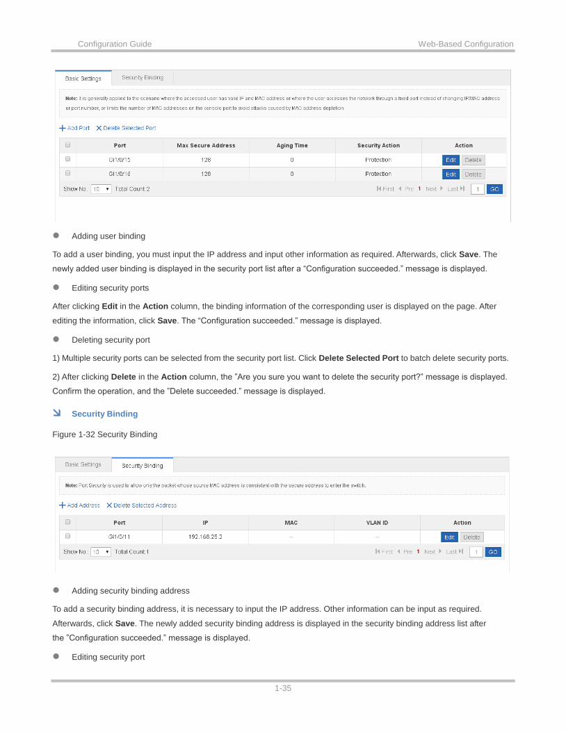
Basic Settings
Figure 1-31 Basic Settings
Configuration Guide Web-Based Configuration
1-35
Adding user binding
To add a user binding, you must input the IP address and input other information as required. Afterwards, click Save. The
newly added user binding is displayed in the security port list after a “Configuration succeeded.” message is displayed.
Editing security ports
After clicking Edit in the Action column, the binding information of the corresponding user is displayed on the page. After
editing the information, click Save. The “Configuration succeeded.” message is displayed.
Deleting security port
1) Multiple security ports can be selected from the security port list. Click Delete Selected Port to batch delete security ports.
2) After clicking Delete in the Action column, the ”Are you sure you want to delete the security port?” message is displayed.
Confirm the operation, and the ”Delete succeeded.” message is displayed.
Security Binding
Figure 1-32 Security Binding
Adding security binding address
To add a security binding address, it is necessary to input the IP address. Other information can be input as required.
Afterwards, click Save. The newly added security binding address is displayed in the security binding address list after
the ”Configuration succeeded.” message is displayed.
Editing security port

Configuration Guide Web-Based Configuration
1-36
After clicking Edit in the Action column, the binding information of the corresponding user is displayed on the page. After
editing the information, click Save. The ”Configuration succeeded.” message is displayed.
Deleting security binding address
1) You can select multiple addresses from the security binding address list and click Delete Selected Address to batch
delete addresses.
2) After clicking Delete in the Action column, the “Are you sure you want to delete the port?” message is displayed.
After confirming the operation, the ”Delete succeeded.” message is displayed.
1.3.4.5 NFPP
Network Foundation Protection Policy (NFPP) provides guards for switches.
Malicious attacks are always found in the network environment. These attacks bring heavy burdens to switches, resulting in
high CPU usage and operational troubles. NFPP can effectively protect the system from these attacks. Facing attacks, NFPP
maintains the proper running of various system services with a low CPU load, thereby ensuring the stability of the entire
network.
ARP Guard
In local area networks (LANs), IP addresses are mapped to MAC addresses through ARP, which has a significant role in
safeguarding network security. ARP-based DoS attacks mean that a large number of unauthorized ARP packets are sent to
the gateway through the network, causing the failure of the gateway to provide services for normal hosts. To prevent such
attacks, limit the rate of ARP packets and identify and isolate the attack source.
IP Guard
Many hacker attacks and network virus intrusions start from scanning active hosts in the network. Therefore, many scanning
packets rapidly occupy the network bandwidth, causing network communication failure. To solve this problem, Ruijie
switches provide IP guard function to prevent hacker scanning and Blaster Worm viruses and reduce the CPU load.
ICMP Guard
ICMP is a common approach to diagnose network failures. After receiving an ICMP echo request from a host, the router or
switch returns an ICMP echo reply. The preceding process requires the CPU to process the packets, thereby definitely
consuming part of CPU resources. If an attacker sends a large number of ICMP echo requests to the destination device,
massive CPU resources on the device will be consumed heavily, and the device may even fail to work properly. This type of
attacks is called ICMP flood. To prevent this type of attacks, limit the rate of ICMP packets and find and isolate the attack
source.
DHCP Guard
DHCP is widely used in LANs to dynamically assign IP addresses. It is significant to network security. Currently, the most
common DHCP attack, also called DHCP exhaustion attack, uses faked MAC addresses to broadcast DHCP requests.
Various attack tools on the Internet can easily complete this type of attack. A network attacker can send sufficient DHCP
requests to use up the address space provided by the DHCP server within a period. In this case, authorized hosts will fail to

Configuration Guide Web-Based Configuration
1-37
request DHCP IP addresses and thereby fail to access the network. To prevent this type of attacks, limit the rate of DHCP
packets and find and isolate the attack source.
DHCPv6 Guard
DHCP version 6 (DHCPv6) is widely used in LANs to dynamically assign IPv6 addresses. Both DHCP version 4 (DHCPv4)
and DHCPv6 have security problems. Attacks to DHCPv4 apply also to DHCPv6. A network attacker can send a large
number of DHCPv6 requests to use up the address space provided by the DHCPv6 server within a period. In this case,
authorized hosts will fail to request IPv6 addresses and thereby fail to access the network. To prevent this type of attacks,
limit the rate of DHCPv6 packets and find and isolate the attack source.
ND Guard
Neighbor Discovery (ND) is mainly used in IPv6 networks to perform address resolution, router discovery, prefix discovery,
and redirection. ND uses five types of packets: Neighbor Solicitation (NS), Neighbor Advertisement (NA), Router Solicitation
(RS), Router Advertisement (RA), and Redirect. These packets are called ND packets.
ND snooping listens to ND packets in the network to filter unauthorized ND packets. It also monitors IPv6 hosts in the
network and bind monitored ones to ports to prevent IPv6 address stealing. ND snooping requires ND packets to be sent to
the CPU. If ND packets are sent at a very high rate, the CPU will be attacked. Therefore, ND guard must be provided to limit
the rate of ND packets.
The following figure shows the NFPP Settings page.
Figure 1-33 NFPP

Configuration Guide Web-Based Configuration
1-38
Various guard functions can be enabled or disabled. After setting, click Save. The ”Save succeeded.” message is displayed.
To restore to default settings, click Restore Default Settings.
1.3.4.6 Storm Control
When a local area network (LAN) has excess broadcast data flows, multicast data flows, or unknown unicast data flows, the
network speed will slow down and packet transmission will have an increased timeout probability. This situation is called a
LAN storm. A storm may occur when topology protocol execution or network configuration is incorrect.
Storm control can be implemented to limit broadcast data flows, multicast data flows, or unknown unicast data flows. If the
rate of data flows received by a device port is within the configured bandwidth threshold, packets-per-second threshold, or
kilobits-per-second threshold, the data flows are permitted to pass through. If the rate exceeds the thresholds, excess data
flows are discarded until the rate falls within the thresholds. This prevents flood data from entering the LAN causing a storm.
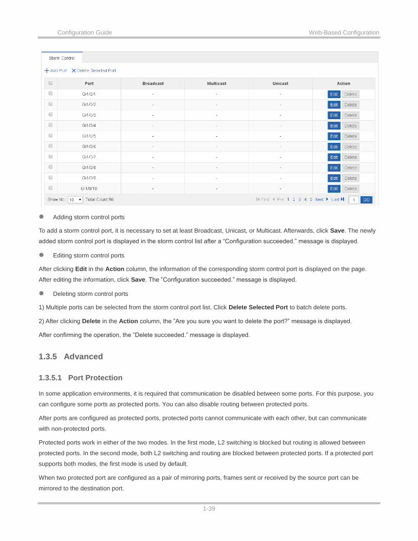
The following figure shows the Storm Control Settings page.
Figure 1-34 Storm Control Settings
Configuration Guide Web-Based Configuration
1-39
Adding storm control ports
To add a storm control port, it is necessary to set at least Broadcast, Unicast, or Multicast. Afterwards, click Save. The newly
added storm control port is displayed in the storm control list after a “Configuration succeeded.” message is displayed.
Editing storm control ports
After clicking Edit in the Action column, the information of the corresponding storm control port is displayed on the page.
After editing the information, click Save. The ”Configuration succeeded.” message is displayed.
Deleting storm control ports
1) Multiple ports can be selected from the storm control port list. Click Delete Selected Port to batch delete ports.
2) After clicking Delete in the Action column, the ”Are you sure you want to delete the port?” message is displayed.
After confirming the operation, the ”Delete succeeded.” message is displayed.
1.3.5 Advanced
1.3.5.1 Port Protection
In some application environments, it is required that communication be disabled between some ports. For this purpose, you
can configure some ports as protected ports. You can also disable routing between protected ports.
After ports are configured as protected ports, protected ports cannot communicate with each other, but can communicate
with non-protected ports.
Protected ports work in either of the two modes. In the first mode, L2 switching is blocked but routing is allowed between
protected ports. In the second mode, both L2 switching and routing are blocked between protected ports. If a protected port
supports both modes, the first mode is used by default.
When two protected port are configured as a pair of mirroring ports, frames sent or received by the source port can be
mirrored to the destination port.

Configuration Guide Web-Based Configuration
1-40
Currently, only an Ethernet physical port or AP port can be configured as a protected port. When an AP port is configured as
a protected port, all of its member ports are configured as protected ports.
The following figure shows the Port Protect Settings page.
Figure 1-35 Port Protect Settings
To set a port as a protection port, select a port on the panel and click Save. The ”Save succeeded.” message is displayed.
1.3.5.2 DHCP
Dynamic Host Configuration Protocol (DHCP) is a client/server protocol that automatically provides an Internet Protocol (IP)
host with its IP address and other related configuration information such as the subnet mask and default gateway. RFCs
2131 and 2132 define DHCP as an Internet Engineering Task Force (IETF) standard based on Bootstrap Protocol (BOOTP),
a protocol with which DHCP shares many implementation details. DHCP allows hosts to obtain required TCP/IP
configuration information from a DHCP server.
DHCP supports three mechanisms for IP address allocation. In "automatic allocation", DHCP assigns a permanent IP
address to a client. In "dynamic allocation", DHCP assigns an IP address to a client for a limited period of time (or until the
client explicitly relinquishes the address). In "static allocation", a client's IP address is assigned by the network administrator,
and DHCP is used simply to convey the assigned address to the client. A particular network will use one or more of these
mechanisms, depending on the policies of the network administrator.
DCHP allows you to perform DHCP settings and static address allocation, and access the client list.
DHCP Settings
The following figure shows the DHCP Settings page.

Configuration Guide Web-Based Configuration
1-41
Figure 1-36 DHCP Settings
Adding DHCP
To add an address pool name, you must configure IP Address Range, Mask, Default Gateway, and Lease Time. Afterwards,
click Save. The newly added address pool name is displayed in the DHCP list after the ”Save succeeded.” message is
displayed.
Editing DHCP
After clicking Edit in the Action column, the information of the corresponding DHCP is displayed on the page. After editing
the information, click Save. The “Save succeeded.” message is displayed.
Deleting DHCP
1) Multiple DHCPs from the DHCP list can be selected. Click Delete Selected DHCP to batch delete DHCPs.
2) After you click Delete in the Action column, the “Are you sure you want to delete the address pool?” message is displayed.
After confirming the operation, a “Delete succeeded.” message is displayed.
Enabling DHCP
Turn on the DHCP service switch to enable the DHCP service.
Static Address
The following figure shows the Client Display page.
Figure 1-37 Client Display
Adding static address

Configuration Guide Web-Based Configuration
1-42
To add a static address, you must configure Client Name, Client IP Address, and Client MAC Address and you can configure
other parameters as required. Afterwards, click Save. The newly added static address is displayed in the static address list
after the ”Save succeeded.” message is displayed.
Editing static address
After you click Edit in the Action column, the information of the corresponding static address is displayed on the page. After
editing the information, click Save. the ”Save succeeded.” message is displayed.
Deleting static address
1) Multiple static addresses from the static address list can be selected. Click Delete Selected Address to batch delete
static addresses.
2) After clicking Delete in the Action column, the ”Are you sure you want to delete the static address?” message is displayed.
After confirming the operation, the ”Delete succeeded.” message is displayed.
Client Display
The following figure shows the ACL List page.
Figure 1-38 Client Display
Search by IP address
Type an IP address in the search box for search.
Binding MAC address to dynamic IP addresses
Multiple clients from the client list can be selected. Click Bind MAC to Dynamic IP for binding.
1.3.5.3 ACL
Access control list (ACL) is also called access list or firewall. It is even called packet filtering in some documents. The ACL
defines rules to determine whether to forward or drop data packets arriving at a network interface.
Time-bases ACLs are Access Lists that enable you to restrict or allow resources based on time periods.
ACL List
The following figure shows the ACL List page.

Configuration Guide Web-Based Configuration
1-43
Figure 1-39 ACL List
Adding ACL
To add an ACL, click Add ACL, and perform settings on the displayed page (ACL List is mandatory). Afterwards, click OK. If
the ”Add succeeded.” message is displayed, the add operation is successful. In this case, the newly added ACL is displayed
in the ACL List drop-down list.
Deleting ACL
Select the ACL to be deleted from the ACL List drop-down list and click Delete ACL. The ”Delete succeeded.’ message is
displayed.
Adding Access rule
To add an ACL rule, it is necessary to select the access control type, protocol, effective time, and IP address. Afterwards,
click Save. The newly added ACL rule is displayed in the ACL rule list after the ”Add succeeded.” message is displayed.
Editing access rule
After clicking Edit in the Action column, the information of the corresponding ACL rule is displayed on the page. After editing
the information, click Save. The “Edit succeeded.” message is displayed.
Deleting access rule
1) Multiple access rules from the ACL rule list can be selected. Click Delete Selected Access Rule to batch delete access
rules.
2) After clicking Delete in the Action column, the “Are you sure you want to delete the access rule?” message is displayed.
After confirming the operation, a ”Delete succeeded.” message is displayed.
Moving access rule
Enter the serial number of the ACL to be moved and click Move. The ”Operation succeeded.” message is displayed.
ACL Time
The following figure shows the ACL Time page.
Figure 1-40 ACL Time

Configuration Guide Web-Based Configuration
1-44
Adding ACL time
To add an ACL time, you must configure Time Object , Day and Time Period. Afterwards, click Save. The newly added ACL
time is displayed in the ACL time list after a “Save succeeded.” message is displayed.
Editing ACL time
After clicking Edit in the Action column, the information of the corresponding ACL time is displayed on the page. After editing
the information, click Save. A “Save succeeded.” message is displayed.
Deleting ACL time
Multiple time objects can be selected from the ACL time list. Click Delete Selected Time Object to batch delete time objects.
ACL Application
The following figure shows the ACL Application page.
Figure 1-41 ACL Application
Add ACL application
To add an ACL application, it is necessary to set the ACL application time and select ACL, filtration direction, and port.
Afterwards, click Save. The newly added ACL application is displayed in the ACL application list after a “Configuration
succeeded.” message is displayed.
Editing ACL application
After clicking Edit in the Action column, the information of the corresponding ACL application is displayed on the page. After
editing the information, click Save. The ”Configuration succeeded.” message is displayed.
Deleting ACL application

Configuration Guide Web-Based Configuration
1-45
1) Multiple ports from the ACL application list can be selected. Click Delete Port to batch delete ports.
2) After clicking Delete in the Action column, the ”Are you sure you want to delete the ACL application?” message is
displayed.
After confirming the operation, the ”Delete succeeded.” message is displayed.
1.3.5.4 QoS
Quality of Service (QoS) indicates that a network can provide a good service capability for specified network communication
by using various infrastructure technologies.
When the network bandwidth is sufficient, all data streams can be properly processed; when network congestion occurs, all
data streams may be discarded. To meet users' requirements for different applications and different levels of service quality,
a network must be able to allocate and schedule resources based on users' requirements and provide different levels of
service quality for different data streams. To be specific, the network can process real-time and important data packets in
higher priorities and process non-real-time and common data packets in lower priorities and even discard the data packets
upon network congestion.
The "doing the best" forwarding mechanism used by traditional networks cannot meet the requirements any longer and then
QoS comes into being. QoS-enabled devices provide transmission QoS quality service. A transmission priority can be
assigned to data streams of a type to identify the importance of the data streams. Then, the devices provide forwarding
policies for different priorities, congestion mitigation and other mechanisms to provide special transmission services for these
data streams. A network environment configured with QoS can provide predictability for network performance, effectively
allocate network bandwidth, and reasonably utilize network resources.
A QoS policy comprises three elements: class, policy and flow behavior.
Class
A class identifies streams and comprises the class name and class rules. You can define the class rules by using commands
to classify packets.
Policy
A policy binds a specific class and specific stream behaviors and comprises the policy name, names of the classes bound,
and stream behaviors. You can bind a specified class and stream behaviors by using a QoS policy and apply the policy to
one or more interfaces.
Flow behavior
Flow behaviors define the QoS actions taken for packets, including priority labeling and traffic supervision for packets.
Class Settings
The following figure shows the Class Settings page.
Figure 1-42 Class Settings

Configuration Guide Web-Based Configuration
1-46
Adding classes
To add a class, select the class name and select an ACL from the ACL list. Afterwards, click Save. The newly added class is
displayed in the class list after the “Add succeeded.” message is displayed.
Editing classes
After clicking Edit in the Action column, the information of the corresponding class is displayed on the page. After editing the
information, click Save. The ”Edit succeeded.” message is displayed.
Deleting class
1) Select multiple classes from the class list. Click Delete Selected Class to batch delete classes.
2) After clicking Delete in the Action column, the “Are you sure you want to delete the item?” message is displayed.
After confirming the operation, the ”Delete succeeded.” message is displayed.
Policy Settings
The following figure shows the Policy Settings page.
Figure 1-43 Policy Settings
Adding policy

Configuration Guide Web-Based Configuration
1-47
To add a policy, set the policy name. Afterwards, click Save. The newly added policy is displayed in the policy list after an
“Add succeeded.” message is displayed.
Deleting policy
Select a specific policy form the policy list and click Delete. The “Are you sure you want to delete the item?” message is
displayed. After confirming the operation, the ”Delete succeeded.” message is displayed.
Adding policy rule
To add a policy rule, configure Bandwidth and Burst Traffic. Other parameters can be configured as required. Afterwards,
click Save. The newly added policy rule is displayed in the policy rule list after the ”Add succeeded.” message is displayed.
Editing policy rule
After clicking Edit in the Action column, the information of the corresponding policy rule is displayed on the page. After
editing the information, click Save. The ”Edit succeeded” message is displayed.
Deleting policy rule
1) Multiple rules from the policy rule list can be selected. Click Delete Selected Rule to batch delete the rule.
2) After clicking Delete in the Action column, the ”Are you sure you want to delete the item?” message is displayed.
After you confirm the operation, the ”Delete succeeded.” message is displayed.
Flow Settings
The following figure shows the Flow Settings page.
Figure 1-44 Flow Settings
Adding application policy ports
To add an application policy port, select the rate limiting direction, trust mode, policy list, and port. Afterwards, click Save.
The newly added application policy port is displayed in the application policy port list after the “Add succeeded.” message is
displayed.
Deleting application policy port
1) Multiple ports from the application policy port list can be selected. Click Delete Selected Port to batch delete ports.

Configuration Guide Web-Based Configuration
1-48
2) After clicking Delete in the Action column, the ”Are you sure you want to delete the item?” message is displayed.
After confirming the operation, a ”Delete succeeded.” message is displayed.
1.3.6 System
The system management page allows you to perform system settings, system upgrade and configuration management and
configure administrator permissions.
1.3.6.1 System Settings
Seven tab pages are available on the system setting page: System Time, Password, Restart, Reset, Enhancement, SNMP,
and DNS.
System time
The network device system clock records the time of events on the device. For example, the time shown in system logs is
obtained from the system clock. Time is recorded in the format of year-month-day, hour:minute:second, day of the week.
When you use a network device for the first time, set its system clock to the current date and time manually.
The following figure shows the System Time page.
Figure 1-45 System Time
System time
The current system time is displayed on the page. Current system time can be set manually. Alternatively, you can select
Automatically synchronize with an Internet time server for setting the time. Afterwards, click Save. The ”Configuration
succeeded.” message is displayed.
When the management IP address changes, you must ensure that the new IP address is reachable. Otherwise, you
cannot login to the web-based management system.
Password
The following figure shows the Password page.

Configuration Guide Web-Based Configuration
1-49
Figure 1-46 Passwords
Modifying the Web-based NMS password
To modify a Web user password, input the old password and input the new password twice. When an incorrect old password
is inputted, the "Incorrect old password" message is displayed in red. In this case, input a correct old password and click
Save.
When you change the Web management password, the enable password is changed accordingly by default.
Modifying the telnet authentication password
You do not need to input the old password before modifying the telnet password. Instead, you only need to input the same
new password twice. Other steps are the same as when modifying the superuser password.
Restoring factory settings
The following figure shows the Reset page.
Figure 1-47 Reset

Configuration Guide Web-Based Configuration
1-50
Importing/exporting configurations
Configurations can be imported to modify the device configuration. Restart the device for the new configuration to install. The
current configuration can be exported as a backup.
Restoring factory settings
Click Restore Factory Settings to restore the current configuration to factory settings.
Enhancement
The following figure shows the Enhancement page.
Figure 1-48 Enhancement

Configuration Guide Web-Based Configuration
1-51
Specify Web Access Port (mandatory) and specify Login Timeout and Device Location as required. Afterwards, click Save.
The “Configuration succeeded.” message is displayed.
SNMP
The Simple Network Management Protocol (SNMP) is by far the dominant protocol in network management. This Protocol
(SNMP) was designed to be an easily implementable, basic network management tool that could be used to meet network
management needs. It is named Simple Network Management Protocol as it is really easy to understand. A key reason for its
widespread acceptance, besides being the chief Internet standard for network management, is its relative simplicity. There
are different versions of SNMP, such as SNMP V1, SNMP V2c, and SNMP V3.
The following figure shows the SNMP page.
Figure 1-49 SNMP
On this page, SNMP Version, Device Location, SNMP Password, and Trap Password are mandatory and other parameters
are optional. After setting, click Save. The “Configuration succeeded.” message is displayed.
DNS
A Domain Name System (DNS) is a distributed database containing mappings between domain names and IP addresses on
the Internet, which facilitate users to access the Internet without remembering IP strings that can be directly accessed by
computers. The process of obtaining an IP address through the corresponding host name is called domain name resolution
(or host name resolution).
DNS consists of a resolver and a DNS server. The DNS server stores the mappings between domain names and IP
addresses of all hosts on the network, and implements mutual conversion between the domain names and IP addresses.
Both the TCP and UDP port IDs of DNS are 53, and generally a UDP port is used.
The following figure shows the DNS page.
Figure 1-50 DNS

Configuration Guide Web-Based Configuration
1-52
Specify DNS Server and click Save. The “Configuration succeeded.” message is displayed.
1.3.6.2 System Upgrade
Two tab pages are available on the system upgrade page: Upgrade Local and Upgrade Online.
Upgrade Local
The following figure shows the Upgrade Local page.
Figure 1-51 Upgrade Local
Click file…, select a bin file stored locally, and click Upgrade to start local upgrade.
Upgrade Online
The following figure shows the Upgrade Online page.
Figure 1-52 Upgrades Online

Configuration Guide Web-Based Configuration
1-53
If a version later than the current version is available, click Detect New Version to upgrade the Web package to the latest
version.
1.3.6.3 Administrator Permissions
The Administrator Permissions page allows configuration of administrator permissions.
The following figure shows the Administrator Permissions page.
Figure 1-53 Administrator Permissions
Adding user
To add a user, input the username, password, and authorized page (by default, the authorized page is all pages). Afterwards,
click Save. All users are displayed in the administrator list after a “Configuration succeeded.” message is displayed.
Two default users are available, that is, super administrator (admin) and guest (guest). Super administrator admin can
modify the permissions of other administrators. An administrator can access all pages except the Administrator
Permissions page, while a guest can only access the home page. Default users cannot be deleted.
1.3.6.4 System Logging
Status changes (such as link up and down) or abnormal events may occur anytime. Ruijie products provide the syslog
mechanism to automatically generate messages (log packets) in fixed format upon status changes or occurrence of events.
These messages are displayed on the related windows such as the Console or monitoring terminal, recorded on media such
as the memory buffer or log files, or sent to a group of log servers on the network so that the administrator can analyze
network performance and identify faults based on these log packets. Log packets can be added with the timestamps and
sequence numbers and classified by severity level so that the administrator can conveniently read and manage log packets.
Two tab pages are available on the system log page: Log Server Settings and Display System Log.
Log Server Settings
The following figure shows the Log Server Settings page.
Figure 1-54 Log Server Settings

Configuration Guide Web-Based Configuration
1-54
Set various parameters such as Server IP Address and Logging Level. The device sends the SYSLOG log to the
corresponding server after the configuration is complete.
Display System Log
The following figure shows the Display System Log page.
Figure 1-55 Display System Log
The current log information is displayed in the text box. Click Update Log to refresh log information.

Configuration Guide Web-Based Configuration
1-55
1.3.6.5 Network Detection
Three tab pages are available on the network connection detection page: Ping, Tracert, and Cable Detection.
Ping
The ping tool sends an Internet Control Message Protocol (ICMP) Request message to the destination host to request the for
an ICMP Echo Reply message. In this way, the ping tool determines the delay and the connectivity between the two network
devices.
The following figure shows the Ping page.
Figure 1-56 Ping
Input the destination IP address and click Detect. The detection result is then displayed in the text box.
Tracert
The Tracert tool uses the Time To Live (TTL) field in the headers of the ICMP and IP messages for the test First, the Tracert
tool on the network device sends an ICMP Request message with TTL 1 to the destination host. After receiving the message,
the first router on the path decreases the TTL by 1. As the TTL becomes 0, the router drops the packets and returns an ICMP
time exceeded message to the network device. After receiving this message, the Tracert tool learns that this router exists on
this path, and then sends an ICMP Request packet with TTL 2 to the destination host to discover the second router. Each
time the Tracert tool increases the TTL in the ICMP Request message by 1 to discover one more router. This process is
repeated until a data packet reaches the destination host. After the packet reaches the destination host, the host returns an

Configuration Guide Web-Based Configuration
1-56
ICMP Echo message instead of an ICMP time exceeded message to the network device. Then, the Tracert tool finishes the
test and displays the path from the network device to the destination host.
The following figure shows the Tracert page.
Figure 1-57 Tracert
Input the destination IP address and click Detect. The detection result is displayed in the text box after a short time.
Cable Detection
When a cable is short-circuited or disconnected, cable detection helps you determine the working status of the cable. Only a
physical port using copper as the medium supports cable detection. A physical port using fiber as the medium or an AP port
does not support cable detection. When cable detection is performed on an operational interface, the interface will be
temporarily disconnected, and then re-connected.
The following figure shows the Cable Detection page.
Figure 1-58 Cable Detection

Configuration Guide Web-Based Configuration
1-57
Select a port on the panel and click Detect. After a short time, the detection result is displayed below the Detect button.
Figure 1-59 Cable detection result.