cisco trustsec how-to guide: global switch configuration · howto-10-universal_switch_config 5...
TRANSCRIPT
Cisco TrustSec How-To Guide: Global Switch Configuration
For Comments, please email: [email protected] Current Document Version: 3.0 August 27, 2012
HowTo-10-Universal_Switch_Config 2
Table of Contents
Table of Contents ............................................................................................................................ 2
Introduction .................................................................................................................................... 3 What Is the Cisco TrustSec System? ......................................................................................................................................................................... 3 About the TrustSec How-To Guides .......................................................................................................................................................................... 3
What does it mean to be ‘TrustSec Certified’? ................................................................................................................................................... 4
Global Switch Configuration ........................................................................................................... 5 Switch Configuration – Global Settings ............................................................................................................................................................... 5 Example Global Configuration .............................................................................................................................................................................. 10
Switches: Universal Switchport Configuration ................................................................................................................................................ 12
Appendix A: References ............................................................................................................... 16 Cisco TrustSec System: ................................................................................................................................................................................................ 16 Device Configuration Guides: ................................................................................................................................................................................... 16
HowTo-10-Universal_Switch_Config 3
Introduction
What Is the Cisco TrustSec System?
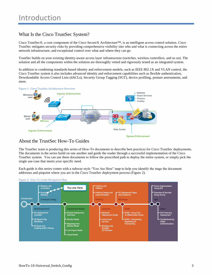
Cisco TrustSec®, a core component of the Cisco SecureX Architecture™, is an intelligent access control solution. Cisco
TrustSec mitigates security risks by providing comprehensive visibility into who and what is connecting across the entire
network infrastructure, and exceptional control over what and where they can go.
TrustSec builds on your existing identity-aware access layer infrastructure (switches, wireless controllers, and so on). The
solution and all the components within the solution are thoroughly vetted and rigorously tested as an integrated system.
In addition to combining standards-based identity and enforcement models, such as IEEE 802.1X and VLAN control, the
Cisco TrustSec system it also includes advanced identity and enforcement capabilities such as flexible authentication,
Downloadable Access Control Lists (dACLs), Security Group Tagging (SGT), device profiling, posture assessments, and
more.
Figure 1: Cisco TrustSec Architecture Overview
About the TrustSec How-To Guides
The TrustSec team is producing this series of How-To documents to describe best practices for Cisco TrustSec deployments.
The documents in the series build on one another and guide the reader through a successful implementation of the Cisco
TrustSec system. You can use these documents to follow the prescribed path to deploy the entire system, or simply pick the
single use-case that meets your specific need.
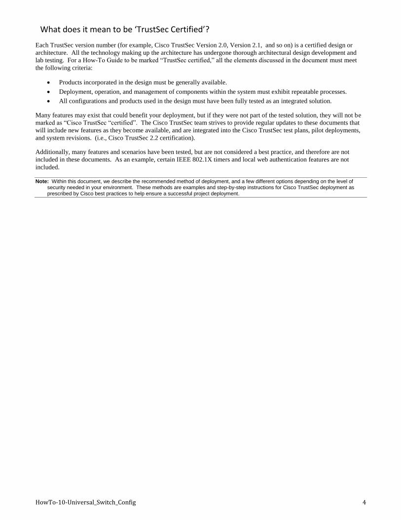
Each guide is this series comes with a subway-style “You Are Here” map to help you identify the stage the document
addresses and pinpoint where you are in the Cisco TrustSec deployment process (Figure 2).
Figure 2: How-To Guide Navigation Map
SXP
Data Center
Wireless user
Campus Network Wired
user
Egress Enforcement
MACsec
Profiler
Posture
Guest Services
Security
Gro
up Tag
RADIUS
Ingress Enforcement
Ingress Enforcement
Security
Group Tag
HowTo-10-Universal_Switch_Config 4
What does it mean to be ‘TrustSec Certified’?
Each TrustSec version number (for example, Cisco TrustSec Version 2.0, Version 2.1, and so on) is a certified design or
architecture. All the technology making up the architecture has undergone thorough architectural design development and
lab testing. For a How-To Guide to be marked “TrustSec certified,” all the elements discussed in the document must meet
the following criteria:
Products incorporated in the design must be generally available.
Deployment, operation, and management of components within the system must exhibit repeatable processes.
All configurations and products used in the design must have been fully tested as an integrated solution.
Many features may exist that could benefit your deployment, but if they were not part of the tested solution, they will not be
marked as “Cisco TrustSec “certified”. The Cisco TrustSec team strives to provide regular updates to these documents that
will include new features as they become available, and are integrated into the Cisco TrustSec test plans, pilot deployments,
and system revisions. (i.e., Cisco TrustSec 2.2 certification).
Additionally, many features and scenarios have been tested, but are not considered a best practice, and therefore are not
included in these documents. As an example, certain IEEE 802.1X timers and local web authentication features are not
included.
Note: Within this document, we describe the recommended method of deployment, and a few different options depending on the level of security needed in your environment. These methods are examples and step-by-step instructions for Cisco TrustSec deployment as prescribed by Cisco best practices to help ensure a successful project deployment.
HowTo-10-Universal_Switch_Config 5
Global Switch Configuration
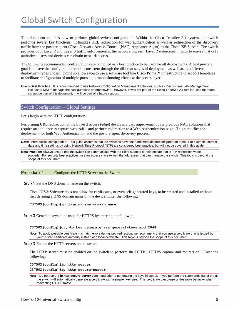
This document explains how to perform global switch configuration. Within the Cisco TrustSec 2.1 system, the switch
performs several key functions. It handles URL redirection for web authentication as well as redirection of the discovery
traffic from the posture agent (Cisco Network Access Control [NAC] Appliance Agent) to the Cisco ISE Server. The switch
provides both Layer 2 and Layer 3 traffic enforcement at the network ingress. Layer 2 enforcement helps to ensure that only
authorized users and devices can obtain network access.
The following recommended configurations are compiled as a best practice to be used for all deployments. A best practice
goal is to have the configuration remain consistent through the different stages of deployment as well as the different
deployment types chosen. Doing so allows you to use a software tool like Cisco Prime™ Infrastructure to set port templates
to facilitate configuration of multiple ports and troubleshooting efforts at the access layer.
Cisco Best Practice: It is recommended to use Network Configuration Management solutions, such as Cisco Prime LAN Management Solution (LMS) to manage the configurations enterprisewide. However, it was not part of the Cisco TrustSec 2.1 test lab, and therefore cannot be part of this document. It will be part of a future version.
Switch Configuration – Global Settings
Let’s begin with the HTTP configuration.
Performing URL redirection at the Layer 2 access (edge) device is a vast improvement over previous NAC solutions that
require an appliance to capture web traffic and perform redirection to a Web Authentication page. This simplifies the
deployment for both Web Authentication and the posture agent discovery process.
Note: Prerequisite configuration: This guide assumes that the switches have the fundamentals preconfigured on them. For example, correct date and time settings by using Network Time Protocol (NTP) are considered best practice, but will not be covered in this guide.
Best Practice: Always ensure that the switch can communicate with the client subnets to help ensure that HTTP redirection works properly. For security best practices, use an access class to limit the addresses that can manage the switch. This topic is beyond the scope of this document.
Procedure 1 Configure the HTTP Server on the Switch
Set the DNS domain name on the switch.
Cisco IOS® Software does not allow for certificates, or even self-generated keys, to be created and installed without
first defining a DNS domain name on the device. Enter the following:
C3750X(config)#ip domain-name domain_name
Generate keys to be used for HTTPS by entering the following:
C3750X(config)#crypto key generate rsa general-keys mod 2048
Note: To avoid possible certificate mismatch errors during web redirection, we recommend that you use a certificate that is issued by your trusted certificate authority instead of a local certificate. This topic is beyond the scope of this document.
Enable the HTTP servers on the switch.
The HTTP server must be enabled on the switch to perform the HTTP / HTTPS capture and redirection. Enter the
following:
C3750X(config)#ip http server
C3750X(config)#ip http secure-server
Note: Do not run the ip http secure-server command prior to generating the keys in step 2. If you perform the commands out of order, the switch will automatically generate a certificate with a smaller key size. This certificate can cause undesirable behavior when redirecting HTTPS traffic.
HowTo-10-Universal_Switch_Config 6
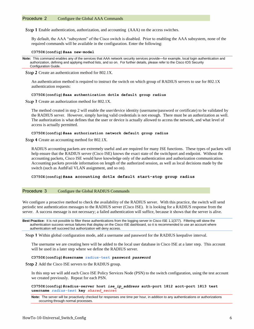
Procedure 2 Configure the Global AAA Commands
Enable authentication, authorization, and accounting (AAA) on the access switches.
By default, the AAA “subsystem” of the Cisco switch is disabled. Prior to enabling the AAA subsystem, none of the
required commands will be available in the configuration. Enter the following:
C3750X(config)#aaa new-model
Note: This command enables any of the services that AAA network security services provide—for example, local login authentication and authorization, defining and applying method lists, and so on. For further details, please refer to the Cisco IOS Security Configuration Guide.
Create an authentication method for 802.1X.
An authentication method is required to instruct the switch on which group of RADIUS servers to use for 802.1X
authentication requests:
C3750X(config)#aaa authentication dot1x default group radius
Create an authorization method for 802.1X.
The method created in step 2 will enable the user/device identity (username/password or certificate) to be validated by
the RADIUS server. However, simply having valid credentials is not enough. There must be an authorization as well.
The authorization is what defines that the user or device is actually allowed to access the network, and what level of
access is actually permitted.
C3750X(config)#aaa authorization network default group radius
Create an accounting method for 802.1X.
RADIUS accounting packets are extremely useful and are required for many ISE functions. These types of packets will
help ensure that the RADIUS server (Cisco ISE) knows the exact state of the switchport and endpoint. Without the
accounting packets, Cisco ISE would have knowledge only of the authentication and authorization communication.
Accounting packets provide information on length of the authorized session, as well as local decisions made by the
switch (such as AuthFail VLAN assignment, and so on).
C3750X(config)#aaa accounting dot1x default start-stop group radius
Procedure 3 Configure the Global RADIUS Commands
We configure a proactive method to check the availability of the RADIUS server. With this practice, the switch will send
periodic test authentication messages to the RADIUS server (Cisco ISE). It is looking for a RADIUS response from the
server. A success message is not necessary; a failed authentication will suffice, because it shows that the server is alive.
Best Practice: It is not possible to filter these authentications from the logging server in Cisco ISE 1.1(377). Filtering will skew the authentication success versus failures that display on the Cisco ISE dashboard, so it is recommended to use an account where authentication will succeed but authorization will deny access.
Within global configuration mode, add a username and password for the RADIUS keepalive interval.
The username we are creating here will be added to the local user database in Cisco ISE at a later step. This account
will be used in a later step where we define the RADIUS server.
C3750X(config)#username radius-test password password
Add the Cisco ISE servers to the RADIUS group.
In this step we will add each Cisco ISE Policy Services Node (PSN) to the switch configuration, using the test account
we created previously. Repeat for each PSN.
C3750X(config)#radius-server host ise_ip_address auth-port 1812 acct-port 1813 test
username radius-test key shared_secret
Note: The server will be proactively checked for responses one time per hour, in addition to any authentications or authorizations occurring through normal processes.
HowTo-10-Universal_Switch_Config 7
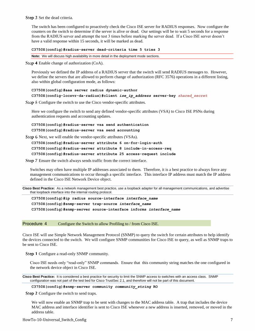
Set the dead criteria.
The switch has been configured to proactively check the Cisco ISE server for RADIUS responses. Now configure the
counters on the switch to determine if the server is alive or dead. Our settings will be to wait 5 seconds for a response
from the RADIUS server and attempt the test 3 times before marking the server dead. If a Cisco ISE server doesn’t
have a valid response within 15 seconds, it will be marked as dead.
C3750X(config)#radius-server dead-criteria time 5 tries 3
Note: We will discuss high availability in more detail in the deployment mode sections.
Enable change of authorization (CoA).
Previously we defined the IP address of a RADIUS server that the switch will send RADIUS messages to. However,
we define the servers that are allowed to perform change of authorization (RFC 3576) operations in a different listing,
also within global configuration mode, as follows:
C3750X(config)#aaa server radius dynamic-author
C3750X(config-locsvr-da-radius)#client ise_ip_address server-key shared_secret
Configure the switch to use the Cisco vendor-specific attributes.
Here we configure the switch to send any defined vendor-specific attributes (VSA) to Cisco ISE PSNs during
authentication requests and accounting updates.
C3750X(config)#radius-server vsa send authentication
C3750X(config)#radius-server vsa send accounting
Next, we will enable the vendor-specific attributes (VSAs).
C3750X(config)#radius-server attribute 6 on-for-login-auth
C3750X(config)#radius-server attribute 8 include-in-access-req
C3750X(config)#radius-server attribute 25 access-request include
Ensure the switch always sends traffic from the correct interface.
Switches may often have multiple IP addresses associated to them. Therefore, it is a best practice to always force any
management communications to occur through a specific interface. This interface IP address must match the IP address
defined in the Cisco ISE Network Device object.
Cisco Best Practice: As a network management best practice, use a loopback adapter for all management communications, and advertise that loopback interface into the internal routing protocol.
C3750X(config)#ip radius source-interface interface_name
C3750X(config)#snmp-server trap-source interface_name
C3750X(config)#snmp-server source-interface informs interface_name
Procedure 4 Configure the Switch to allow Profiling to / from Cisco ISE.
Cisco ISE will use Simple Network Management Protocol (SNMP) to query the switch for certain attributes to help identify
the devices connected to the switch. We will configure SNMP communities for Cisco ISE to query, as well as SNMP traps to
be sent to Cisco ISE.
Configure a read-only SNMP community.
Cisco ISE needs only “read-only” SNMP commands. Ensure that this community string matches the one configured in
the network device object in Cisco ISE.
Cisco Best Practice: It is considered a best practice for security to limit the SNMP access to switches with an access class. SNMP
configuration was not part of the test bed for Cisco TrustSec 2.1, and therefore will not be part of this document.
C3750X(config)#snmp-server community community_string RO
Configure the switch to send traps.
We will now enable an SNMP trap to be sent with changes to the MAC address table. A trap that includes the device
MAC address and interface identifier is sent to Cisco ISE whenever a new address is inserted, removed, or moved in the
address table.
HowTo-10-Universal_Switch_Config 8
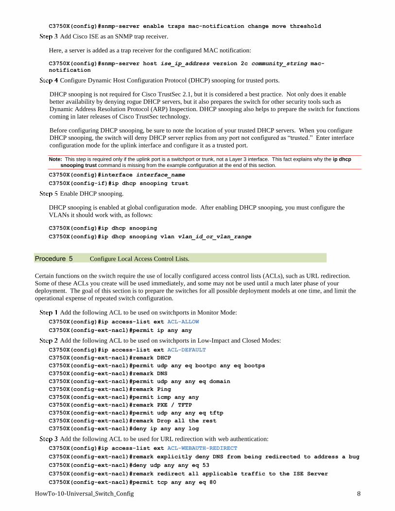
C3750X(config)#snmp-server enable traps mac-notification change move threshold
Add Cisco ISE as an SNMP trap receiver.
Here, a server is added as a trap receiver for the configured MAC notification:
C3750X(config)#snmp-server host ise_ip_address version 2c community_string mac-
notification
Configure Dynamic Host Configuration Protocol (DHCP) snooping for trusted ports.
DHCP snooping is not required for Cisco TrustSec 2.1, but it is considered a best practice. Not only does it enable
better availability by denying rogue DHCP servers, but it also prepares the switch for other security tools such as
Dynamic Address Resolution Protocol (ARP) Inspection. DHCP snooping also helps to prepare the switch for functions
coming in later releases of Cisco TrustSec technology.
Before configuring DHCP snooping, be sure to note the location of your trusted DHCP servers. When you configure
DHCP snooping, the switch will deny DHCP server replies from any port not configured as “trusted.” Enter interface
configuration mode for the uplink interface and configure it as a trusted port.
Note: This step is required only if the uplink port is a switchport or trunk, not a Layer 3 interface. This fact explains why the ip dhcp snooping trust command is missing from the example configuration at the end of this section.
C3750X(config)#interface interface_name
C3750X(config-if)#ip dhcp snooping trust
Enable DHCP snooping.
DHCP snooping is enabled at global configuration mode. After enabling DHCP snooping, you must configure the
VLANs it should work with, as follows:
C3750X(config)#ip dhcp snooping
C3750X(config)#ip dhcp snooping vlan vlan_id_or_vlan_range
Procedure 5 Configure Local Access Control Lists.
Certain functions on the switch require the use of locally configured access control lists (ACLs), such as URL redirection.
Some of these ACLs you create will be used immediately, and some may not be used until a much later phase of your
deployment. The goal of this section is to prepare the switches for all possible deployment models at one time, and limit the
operational expense of repeated switch configuration.
Add the following ACL to be used on switchports in Monitor Mode:
C3750X(config)#ip access-list ext ACL-ALLOW
C3750X(config-ext-nacl)#permit ip any any
Add the following ACL to be used on switchports in Low-Impact and Closed Modes:
C3750X(config)#ip access-list ext ACL-DEFAULT
C3750X(config-ext-nacl)#remark DHCP
C3750X(config-ext-nacl)#permit udp any eq bootpc any eq bootps
C3750X(config-ext-nacl)#remark DNS
C3750X(config-ext-nacl)#permit udp any any eq domain
C3750X(config-ext-nacl)#remark Ping
C3750X(config-ext-nacl)#permit icmp any any
C3750X(config-ext-nacl)#remark PXE / TFTP
C3750X(config-ext-nacl)#permit udp any any eq tftp
C3750X(config-ext-nacl)#remark Drop all the rest
C3750X(config-ext-nacl)#deny ip any any log
Add the following ACL to be used for URL redirection with web authentication:
C3750X(config)#ip access-list ext ACL-WEBAUTH-REDIRECT
C3750X(config-ext-nacl)#remark explicitly deny DNS from being redirected to address a bug
C3750X(config-ext-nacl)#deny udp any any eq 53
C3750X(config-ext-nacl)#remark redirect all applicable traffic to the ISE Server
C3750X(config-ext-nacl)#permit tcp any any eq 80
HowTo-10-Universal_Switch_Config 9
C3750X(config-ext-nacl)#permit tcp any any eq 443
C3750X(config-ext-nacl)#remark all other traffic will be implicitly denied from the
redirection
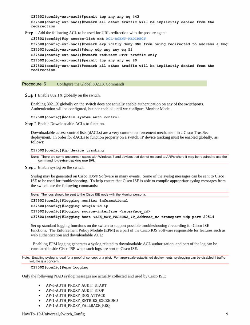
Add the following ACL to be used for URL redirection with the posture agent:
C3750X(config)#ip access-list ext ACL-AGENT-REDIRECT
C3750X(config-ext-nacl)#remark explicitly deny DNS from being redirected to address a bug
C3750X(config-ext-nacl)#deny udp any any eq 53
C3750X(config-ext-nacl)#remark redirect HTTP traffic only
C3750X(config-ext-nacl)#permit tcp any any eq 80
C3750X(config-ext-nacl)#remark all other traffic will be implicitly denied from the
redirection
Procedure 6 Configure the Global 802.1X Commands
Enable 802.1X globally on the switch.
Enabling 802.1X globally on the switch does not actually enable authentication on any of the switchports.
Authentication will be configured, but not enabled until we configure Monitor Mode.
C3750X(config)#dot1x system-auth-control
Enable Downloadable ACLs to function.
Downloadable access control lists (dACLs) are a very common enforcement mechanism in a Cisco TrustSec
deployment. In order for dACLs to function properly on a switch, IP device tracking must be enabled globally, as
follows:
C3750X(config)#ip device tracking
Note: There are some uncommon cases with Windows 7 and devices that do not respond to ARPs where it may be required to use the command ip device tracking use SVI.
Enable syslog on the switch.
Syslog may be generated on Cisco IOS® Software in many events. Some of the syslog messages can be sent to Cisco
ISE to be used for troubleshooting. To help ensure that Cisco ISE is able to compile appropriate syslog messages from
the switch, use the following commands:
Note: The logs should be sent to the Cisco ISE node with the Monitor persona.
C3750X(config)#logging monitor informational
C3750X(config)#logging origin-id ip
C3750X(config)#logging source-interface <interface_id>
C3750X(config)#logging host <ISE_MNT_PERSONA_IP_Address_x> transport udp port 20514
Set up standard logging functions on the switch to support possible troubleshooting / recording for Cisco ISE
functions. The Enforcement Policy Module (EPM) is a part of the Cisco IOS Software responsible for features such as
web authentication and downloadable ACL:
Enabling EPM logging generates a syslog related to downloadable ACL authorization, and part of the log can be
correlated inside Cisco ISE when such logs are sent to Cisco ISE.
Note: Enabling syslog is ideal for a proof of concept or a pilot. For large-scale established deployments, syslogging can be disabled if traffic volume is a concern.
C3750X(config)#epm logging
Only the following NAD syslog messages are actually collected and used by Cisco ISE:
AP-6-AUTH_PROXY_AUDIT_START AP-6-AUTH_PROXY_AUDIT_STOP AP-1-AUTH_PROXY_DOS_ATTACK AP-1-AUTH_PROXY_RETRIES_EXCEEDED AP-1-AUTH_PROXY_FALLBACK_REQ
HowTo-10-Universal_Switch_Config 10
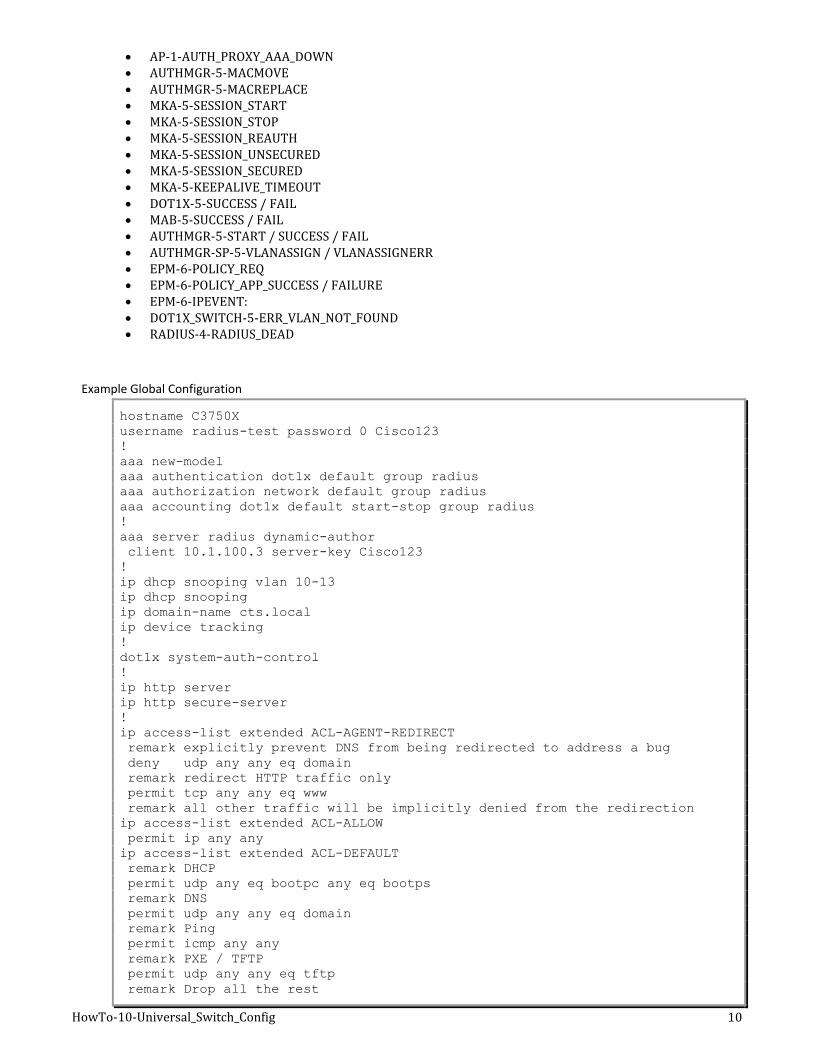
AP-1-AUTH_PROXY_AAA_DOWN AUTHMGR-5-MACMOVE AUTHMGR-5-MACREPLACE MKA-5-SESSION_START MKA-5-SESSION_STOP MKA-5-SESSION_REAUTH MKA-5-SESSION_UNSECURED MKA-5-SESSION_SECURED MKA-5-KEEPALIVE_TIMEOUT DOT1X-5-SUCCESS / FAIL MAB-5-SUCCESS / FAIL AUTHMGR-5-START / SUCCESS / FAIL AUTHMGR-SP-5-VLANASSIGN / VLANASSIGNERR EPM-6-POLICY_REQ EPM-6-POLICY_APP_SUCCESS / FAILURE EPM-6-IPEVENT: DOT1X_SWITCH-5-ERR_VLAN_NOT_FOUND RADIUS-4-RADIUS_DEAD
Example Global Configuration
hostname C3750X
username radius-test password 0 Cisco123
!
aaa new-model
aaa authentication dot1x default group radius
aaa authorization network default group radius
aaa accounting dot1x default start-stop group radius
!
aaa server radius dynamic-author
client 10.1.100.3 server-key Cisco123
!
ip dhcp snooping vlan 10-13
ip dhcp snooping
ip domain-name cts.local
ip device tracking
!
dot1x system-auth-control
!
ip http server
ip http secure-server
!
ip access-list extended ACL-AGENT-REDIRECT
remark explicitly prevent DNS from being redirected to address a bug
deny udp any any eq domain
remark redirect HTTP traffic only
permit tcp any any eq www
remark all other traffic will be implicitly denied from the redirection
ip access-list extended ACL-ALLOW
permit ip any any
ip access-list extended ACL-DEFAULT
remark DHCP
permit udp any eq bootpc any eq bootps
remark DNS
permit udp any any eq domain
remark Ping
permit icmp any any
remark PXE / TFTP
permit udp any any eq tftp
remark Drop all the rest
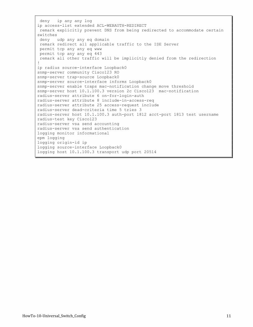
HowTo-10-Universal_Switch_Config 11
deny ip any any log
ip access-list extended ACL-WEBAUTH-REDIRECT
remark explicitly prevent DNS from being redirected to accommodate certain
switches
deny udp any any eq domain
remark redirect all applicable traffic to the ISE Server
permit tcp any any eq www
permit tcp any any eq 443
remark all other traffic will be implicitly denied from the redirection
!
ip radius source-interface Loopback0
snmp-server community Cisco123 RO
snmp-server trap-source Loopback0
snmp-server source-interface informs Loopback0
snmp-server enable traps mac-notification change move threshold
snmp-server host 10.1.100.3 version 2c Cisco123 mac-notification
radius-server attribute 6 on-for-login-auth
radius-server attribute 8 include-in-access-req
radius-server attribute 25 access-request include
radius-server dead-criteria time 5 tries 3
radius-server host 10.1.100.3 auth-port 1812 acct-port 1813 test username
radius-test key Cisco123
radius-server vsa send accounting
radius-server vsa send authentication
logging monitor informational
epm logging
logging origin-id ip
logging source-interface Loopback0
logging host 10.1.100.3 transport udp port 20514
HowTo-10-Universal_Switch_Config 12
Switches: Universal Switchport Configuration
In the previous section, we defined the universal commands for the Global Configuration settings of the access layer
switches, including RADIUS, SNMP, profiling, and AAA methods.
This section focuses on building a single port configuration that can be used across your entire Cisco TrustSec deployment,
regardless of switch type or deployment model you use.
Note: If you are using a bulk configuration tool, such as Cisco Prime LAN Management Solution (LMS) 4.1, you may need to ensure this
command is run prior to any of the commands that follow.
Procedure 1 Set Up Basic Switchport Configurations
Before configuring any of the authentication settings on the switchport, you must make sure that the switchport is configured as a Layer 2 port, not a Layer 3 port. This command is a simple, one-word command that we will run, and from that point on, the other commands we run will all take effect.
Enter interface configuration mode for the switchport range:
C3750X(config)#interface range first_interface - last_interface
Ensure that the ports are Layer 2 switchports.
C3750X(config-if-range)#switchport
Configure the port for Layer 2 edge, using the host macro.
The host macro will automatically run three commands for you. It will configure the port to be an access port
(nontrunk), disable channel groups, and configure spanning tree to be in portfast mode.
C3750X(config-if-range)#switchport host
! – Switch Output:
switchport mode will be set to access
spanning-tree portfast will be enabled
channel group will be disabled
Procedure 2 Authentication Settings – Flexible Authentication and High Availability
The default behavior of 802.1X is to deny access to the network when an authentication fails. This behavior was discovered
to be undesirable in many customer deployments because it does not allow for guest access, nor does it allow employees to
remediate their computer systems and gain full network access. The next phase in handling 802.1X authentication failures
was to provide an “Auth-Fail VLAN” to allow a device/user that failed authentication to be granted access to a VLAN that
provided limited resources.
This step was a step in the right direction, but was still not as practical as needed, especially in environments that must use
MAC Authentication Bypass for all the printers and other nonauthenticating devices. With the default behavior of 802.1X,
an administrator would have to configure ports for printers and other devices that do not have supplicants differently from the
ports on which they planned to do authentication.
Therefore, Cisco created Flexible Authentication (Flex-Auth). Flex-Auth allows a network administrator to set an
authentication order and priority on the switchport, thereby allowing the port to attempt 802.1X, MAC Authentication
Bypass, and then Web Authentication in order. All of these functions are provided while maintaining the same configuration
on all access ports, thereby providing a much simpler operational model for customers than traditional 802.1X deployments.
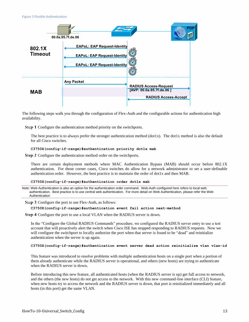
As mentioned previously, there are multiple methods of authentication on a switchport: 802.1X (dot1x), MAC Authentication
Bypass (MAB), and Web-based Authentication (Web-Auth). With 802.1X authentication, the switch sends an identity
request (EAP-Identity-Request) periodically after the link state has changed to “up” (see the “Authentication Settings –
Timers “ section for recommended timer changes). Additionally, the endpoint supplicant should send a periodic EAP over
LAN Start (EAPoL-Start) message into the switchport to speed up authentication. If a device is not able to authenticate, it
merely has to wait until the dot1x timeout occurs, and MAC Authentication Bypass (MAB) will occur. Assuming the device
MAC address is in the correct database, it will then be authorized to access the network (Figure 3).
HowTo-10-Universal_Switch_Config 13
Figure 3 Flexible Authentication
The following steps walk you through the configuration of Flex-Auth and the configurable actions for authentication high
availability.
Configure the authentication method priority on the switchports.
The best practice is to always prefer the stronger authentication method (dot1x). The dot1x method is also the default
for all Cisco switches.
C3750X(config-if-range)#authentication priority dot1x mab
Configure the authentication method order on the switchports.
There are certain deployment methods where MAC Authentication Bypass (MAB) should occur before 802.1X
authentication. For those corner cases, Cisco switches do allow for a network administrator to set a user-definable
authentication order. However, the best practice is to maintain the order of dot1x and then MAB.
C3750X(config-if-range)#authentication order dot1x mab
Note: Web Authentication is also an option for the authentication order command. Web-Auth configured here refers to local web authentication. Best practice is to use central web authentication. For more detail on Web Authentication, please refer the Web Authentication
Configure the port to use Flex-Auth, as follows:
C3750X(config-if-range)#authentication event fail action next-method
Configure the port to use a local VLAN when the RADIUS server is down.
In the “Configure the Global RADIUS Commands” procedure, we configured the RADIUS server entry to use a test
account that will proactively alert the switch when Cisco ISE has stopped responding to RADIUS requests. Now we
will configure the switchport to locally authorize the port when that server is found to be “dead” and reinitialize
authentication when the server is up again.
C3750X(config-if-range)#authentication event server dead action reinitialize vlan vlan-id
This feature was introduced to resolve problems with multiple authentication hosts on a single port when a portion of
them already authenticate while the RADIUS server is operational, and others (new hosts) are trying to authenticate
when the RADIUS server is down.
Before introducing this new feature, all authenticated hosts (when the RADIUS server is up) get full access to network,
and the others (the new hosts) do not get access to the network. With this new command-line interface (CLI) feature,
when new hosts try to access the network and the RADIUS server is down, that port is reinitialized immediately and all
hosts (in this port) get the same VLAN.
EAPoL: EAP Request-Identity
Any Packet
RADIUS Access-Accept
RADIUS Access-Request [AVP: 00.0a.95.7f.de.06 ]
802.1X Timeout
MAB
EAPoL: EAP Request-Identity
EAPoL: EAP Request-Identity
00.0a.95.7f.de.06
PDP
HowTo-10-Universal_Switch_Config 14
Configure the port to allow a phone onto the network when the RADIUS server is down.
A phone is placed on the voice domain after successful authentication by configuring the RADIUS server to pass down
the attribute device-traffic-class=voice. However, when the RADIUS server is not available, the phone won’t be able to
access the voice network and therefore cannot operate. As a result, there is a new feature called Critical Voice VLAN.
With this new feature, when the port is in critical authentication mode and traffic coming from the host is tagged with the
voice VLAN, the device (a phone) is put into the configured voice VLAN for the port. The phone learns the voice
VLAN identification through Cisco Discovery Protocol (CDP), Link Layer Discovery Protocol (LLDP), or DHCP. The
command to enable this feature is:
C3750X(config-if-range)#authentication event server dead action authorize voice
Set the host mode of the port.
The default behavior of an 802.1X-enabled port is to authorize only a single MAC address per port. There are other
options, most notably Multi-Domain Authentication (MDA) and Multiple Authentication (Multi-Auth) modes. During
the initial phases of any Cisco TrustSec deployment, it is best practice to use Multi-Auth mode to ensure that there is no
denial of service while deploying 802.1X.
Note: Port Security is not recommended in a Cisco TrustSec deployment, because 802.1X handles this function natively.
Multi-Auth mode will allow virtually unlimited MAC addresses per switchport, and require an authenticated session for
every MAC address. When the deployment moves into the late stages of the authenticated phase, or into the
enforcement phase, it is then recommended to use Multi-Domain mode. Multi-Domain Authentication will allow a
single MAC address in the data domain and a single MAC address in the voice domain per port.
C3750X(config-if-range)#authentication host-mode multi-auth
Configure the violation action.
When an authentication violation occurs, such as when there are more MAC addresses than are allowed on the port, the
default action is to put the port into an error-disabled state. Although this behavior may seem to be nice and secure, it
can create an accidental denial of service, especially during the initial phases of deployment. Therefore, we will set the
action to be restricted. This mode of operation will allow the first authenticated device to continue with its authorization
and deny any additional devices.
C3750X(config-if-range)#authentication violation restrict
Procedure 3 Authentication Settings – Open Authentication and Additional Steps
802.1X is designed to be binary by default. Successful authentication means the user is authorized to access the network.
Unsuccessful authentication means the user has no access to the network. This paradigm does not lend itself very well to a
modern organization. Most organizations need to do workstation imaging with Pre-Execution Environments (PXE), or may
have some thin clients that have to boot with DHCP and don’t have any way to run a supplicant.
Additionally, when early adopters of 802.1X would deploy authentication companywide, there were repercussions. For
example, supplicants were misconfigured, and unknown devices were unable to authenticate because of a lack of supplicant
and for many other reasons.
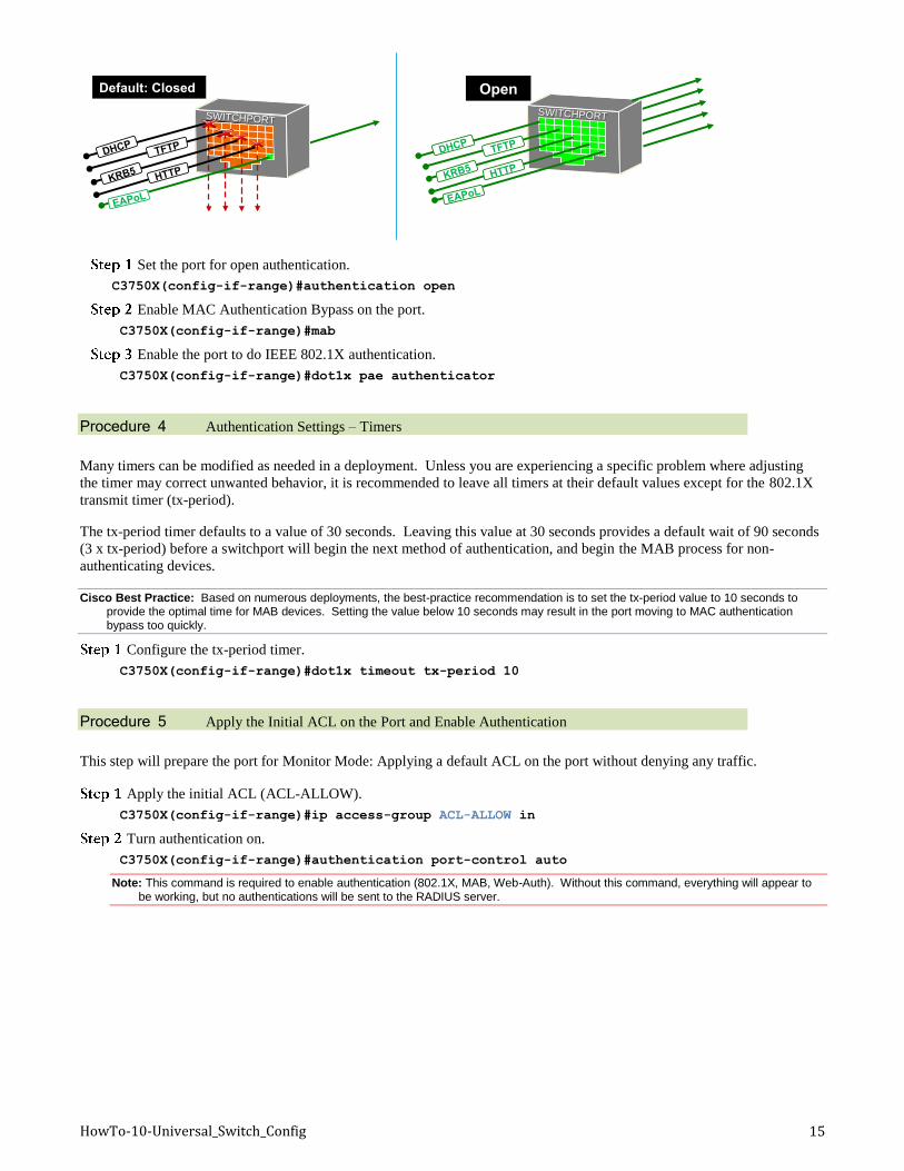
Cisco created open authentication mode to aid with deployments. Open authentication allows all traffic to flow through the
switchport even without the port being authorized. This feature allows authentication to be configured across the entire
organization, while not denying access to any device (Figure 4).
Figure 4 Default Authentication Mode (Closed) Versus Open Authentication Mode
HowTo-10-Universal_Switch_Config 15
Set the port for open authentication.
C3750X(config-if-range)#authentication open
Enable MAC Authentication Bypass on the port.
C3750X(config-if-range)#mab
Enable the port to do IEEE 802.1X authentication.
C3750X(config-if-range)#dot1x pae authenticator
Procedure 4 Authentication Settings – Timers
Many timers can be modified as needed in a deployment. Unless you are experiencing a specific problem where adjusting
the timer may correct unwanted behavior, it is recommended to leave all timers at their default values except for the 802.1X
transmit timer (tx-period).
The tx-period timer defaults to a value of 30 seconds. Leaving this value at 30 seconds provides a default wait of 90 seconds
(3 x tx-period) before a switchport will begin the next method of authentication, and begin the MAB process for non-
authenticating devices.
Cisco Best Practice: Based on numerous deployments, the best-practice recommendation is to set the tx-period value to 10 seconds to provide the optimal time for MAB devices. Setting the value below 10 seconds may result in the port moving to MAC authentication bypass too quickly.
Configure the tx-period timer.
C3750X(config-if-range)#dot1x timeout tx-period 10
Procedure 5 Apply the Initial ACL on the Port and Enable Authentication
This step will prepare the port for Monitor Mode: Applying a default ACL on the port without denying any traffic.
Apply the initial ACL (ACL-ALLOW).
C3750X(config-if-range)#ip access-group ACL-ALLOW in
Turn authentication on.
C3750X(config-if-range)#authentication port-control auto
Note: This command is required to enable authentication (802.1X, MAB, Web-Auth). Without this command, everything will appear to be working, but no authentications will be sent to the RADIUS server.
Default: Closed
SWITCHPORT
DHCP TFTP
KRB5 HTTP
EAPoL
SWITCHPORT
KRB5 HTTP
EAPoL
DHCP TFTP
Open
HowTo-10-Universal_Switch_Config 16
Appendix A: References
Cisco TrustSec System:
http://www.cisco.com/go/trustsec
http://www.cisco.com/en/US/solutions/ns340/ns414/ns742/ns744/landing_DesignZone_TrustSec.html
Device Configuration Guides:
Cisco Identity Services Engine User Guides:
http://www.cisco.com/en/US/products/ps11640/products_user_guide_list.html
For more information about Cisco IOS Software, Cisco IOS XE Software, and Cisco NX-OS Software releases, please refer
to following URLs:
For Cisco Catalyst 2900 series switches:
http://www.cisco.com/en/US/products/ps6406/products_installation_and_configuration_guides_list.html
For Cisco Catalyst 3000 series switches:
http://www.cisco.com/en/US/products/ps7077/products_installation_and_configuration_guides_list.html
For Cisco Catalyst 3000-X series switches:
http://www.cisco.com/en/US/products/ps10745/products_installation_and_configuration_guides_list.html
For Cisco Catalyst 4500 series switches:
http://www.cisco.com/en/US/products/hw/switches/ps4324/products_installation_and_configuration_guides_list.ht
ml
For Cisco Catalyst 6500 series switches:
http://www.cisco.com/en/US/products/hw/switches/ps708/products_installation_and_configuration_guides_list.html
For Cisco ASR 1000 series routers:
http://www.cisco.com/en/US/products/ps9343/products_installation_and_configuration_guides_list.html
For Cisco Wireless LAN Controllers: http://www.cisco.com/en/US/docs/wireless/controller/7.2/configuration/guide/cg.html