research article study of baffle boundary and system...
TRANSCRIPT
Research ArticleStudy of Baffle Boundary and SystemParameters on Liquid-Solid Coupling Vibration ofRectangular Liquid-Storage Structure
Wei Jing1 Xuansheng Cheng12 Wei Shi1 Jin Fan1 and Huan Feng1
1School of Civil Engineering Lanzhou University of Technology Lanzhou Gansu 730050 China2Western Center of Disaster Mitigation in Civil Engineering of the Ministry of Education Lanzhou Gansu 730050 China
Correspondence should be addressed to Xuansheng Cheng cxs702126com
Received 10 December 2015 Accepted 16 February 2016
Academic Editor Salvatore Russo
Copyright copy 2016 Wei Jing et alThis is an open access article distributed under the Creative Commons Attribution License whichpermits unrestricted use distribution and reproduction in any medium provided the original work is properly cited
In order to study the vibration problem of liquid-solid coupling of rectangular liquid-storage structure with horizontal elastic baffleignoring the influence of surface gravitywave two different velocity potential functions corresponding to the liquid above and belowthe elastic baffle are assumed based on the theory of mathematical equation and energy method the formulas of basic frequency ofliquid-solid coupling vibration system are derived the baffle joined to the tank wall with 3 kinds of boundary conditions namelyfour edges simply supported two opposite edges clamped and two opposite edges simply supported and four edges clampedthe influence rules of baffle length-width ratio the ratio of baffle height to liquid level baffle elastic modulus baffle density bafflethickness and liquid density on the coupling vibration performance are studiedThe results show that the frequency of the clampedboundary is minimum the influences of baffle length-width ratio and relative height on the basic frequency are much greater thanthat of the other system parameters the relation between baffle length-width ratio and the frequency is exponential while bafflerelative height has a parabola relation with the frequency the larger the baffle length-width ratio the closer the baffle to the liquidlevel the coupling frequency will be reduced more obviously
1 Introduction
Rectangular liquid-storage structure is widely used in watersupply and drainage system sewage treatment petrochem-ical industry TLD of high rise structure and so on Withthe rapid development of our economy the liquid-storagestructures have already started to develop in the directionof large amount and large scale The special performance ofthis kind of structure is that it will bear extra dynamic liquidpressure under external excitations
As a measure to reduce the liquid sloshing the baffle hasbeen widely used in the field of aerospace automotive storagetanks structural engineering and so on But setting bafflesin the liquid-storage structure not only does the complexityof the structure itself increase but also the analysis difficultyis further increased due to the coupling vibration of elasticbaffle and liquid [1] a large amount of researches on the
structure with baffle has been carried out all over the worldWang et al [2] studied the liquid sloshing characteristicsof the spherical tank with baffle finding that the basicfrequency of the spherical tank is decreased after addingbaffle Yue et al [3] used two potential functions to solvethe liquid sloshing problem of the tank with elastic bafflethe results showed that the baffle position in liquid has agreat influence on the reducing sloshing effect Yang et al[4] carried out finite element simulation calculation andexperimental determination of liquid sloshing in a cylindricalliquid-storage tank with an elastic baffle finding that whenthe baffle was closer to the liquid surface its influenceon the coupling frequency is greater Hao et al [5] usedthe single Lagrangian method to study stable equilibriumproblems of storage tank with different boundary elasticbaffle Biswal and Bhattacharyya [6] considered the dynamicinteraction of liquid-structure-baffle system by using the
Hindawi Publishing CorporationShock and VibrationVolume 2016 Article ID 8613723 10 pageshttpdxdoiorg10115520168613723
2 Shock and Vibration
finite elementmethod and studied the influences of baffle sizeand position on the liquid sloshing and structural responseShahrokhi et al [7] studied the influences of baffle positionon the liquid flow pattern of liquid-storage structure by usingcomputational fluid dynamics (CFD) Wang et al [8] got thepotential functions of each subdomain liquid by using theseparation variable method and superposition principle andstudied the fluid-solid coupling characteristics of the liquid-storage structure with elastic baffle Song et al [9] establisheda mathematical model of water free surface by using theboundary element method in order to solve the problem ofliquid sloshing in a rectangular tank with baffle and pointedout that the reducing sloshing function of baffle is mainlyachieved by changing the frequency distribution of originalliquid-storage structure Xue et al [10] simulated a cubeliquid-storage structure with multibaffles and got the con-clusion that baffle can effectively reduce the amplitude anddynamic liquid pressure of liquid sloshing Wang et al [11]divided the fluid domain into several simple subdomains andthe influences of location inner radius and the number ofcircular baffles on the coupling vibration of the liquid-storagestructure were studied Hasheminejad et al [12] studied thetransient horizontal response of the tank with baffle andthe effective baffle shape that can suppress the lateral forceShekari [13] divided the fluid domain into two parts withbaffle using boundary element method to study the basicmode of liquid-storage structure with baffle summarizingthe maximum seismic responses of the structure with bafflethen the baffle effect on the vibration control of liquid-storage structure is proved Ebrahimian et al [14] appliedthe feature analysis method to study the basic frequency andformation of liquid-storage structure with baffle Goudarziand Farshadmanesh [15] studied the free vibration of liquid-storage structure with different size and different positionbaffle the results showed that the liquid sloshing height wasreduced by 50 owing to adding baffle
In summary although the baffle can exert an inhibitoryeffect on the liquid sloshing of liquid-storage structure itseffect on the fluid-solid coupling vibration is influenced bymany factors So the effect of elastic horizontal baffle on thefluid-solid coupling vibration of rectangular liquid-storagestructure will be studied further in this paper supposing theliquid is of no rotation of no viscosity and incompressiblebecause the occurrence probability of gravity wave in thestructure of civil engineering is small [16] therefore thesurface gravity wave is ignored Assuming that the wallof liquid-storage structure is rigid and its baffle is elastictwo different velocity potential functions corresponding tothe liquid above and below the elastic baffle are definedbased on the theory of mathematical equation and energymethod the formulas of basic frequency of liquid-solid cou-pling vibration of rectangular storage structure with flexiblebaffle are derived the baffle joined to the tank wall with3 kinds of boundary conditions namely four edges simplysupported two opposite edges clamped and two oppositeedges simply supported and four edges clamped the con-clusions can provide theoretical basis for the reducing slosh-ing design of reinforced concrete rectangular liquid-storagestructure
2 Fluid-Solid Coupling Modeland Basic Theory
Assuming that the liquid is in an ideal state the length widthand height of the rectangular liquid-storage structure are 119886 119887and 119888 respectively the distance between elastic baffle and thetank bottom is 119867 liquid level height is ℎ and ℎ is greaterthan119867 supposing the wall is rigid liquid sloshing is of smallamplitude Ignoring hollows in the elastic baffle although inpractical engineering application in order to make the liquidflow through the baffle some holes need to be set in the baffleif the holes are small and arranged in centralized mannertheir effect on the coupling vibration can be ignored whenthe holes layout does not conform to the above provisionsthe calculation results should be modified by considering theliquid flow effect caused by baffle holes [17] the analyticalmodel is shown in Figure 1
When the liquid sloshing is of small amplitude linearpotential flow theory can be used to solve the couplingvibration problem Assuming that the baffle is located belowthe stationary liquid level in this case the velocity potentialsfor both sides of liquid of the baffle can be expressed as1206011(119909 119910 119911 119905) and120601
2(119909 119910 119911 119905) 120601
1and1206012all satisfy the Laplace
equation [18]
nabla2120601119895= 0 119895 = 1 2 (1)
According to the existing literature [19] for commonliquids because 120590120588
119908is small for simplicity liquid surface
tension 120590 can be ignored After neglecting the surface tensionof liquid sloshing the kinematic and dynamic boundaryconditions for the first-order liquid sloshing problem can beexpressed as follows
12059721206011
1205971199052+ 119892
1205971206011
120597119911
100381610038161003816100381610038161003816100381610038161003816119911=ℎ
= 0 (2)
where 119892 is the gravity accelerationOn the contact surface of rigid wall and liquid the liquid
velocity potential functions satisfy the following boundaryconditions
120597120601119895
120597119909
100381610038161003816100381610038161003816100381610038161003816119909=0119886
= 0
120597120601119895
120597119910
100381610038161003816100381610038161003816100381610038161003816119910=0119887
= 0
119895 = 1 2
(3)
1205971206012
120597119911
10038161003816100381610038161003816100381610038161003816119911=0
= 0 (4)
According to Bernoulli equation the relation betweenliquid sloshing pressure and velocity potential is 119875 =
minus120588119908(120597120601120597119905) thus the total sloshing pressure of the baffle
under the action of upper and lower liquid is as follows
119875119867= (minus120588
119908
1205971206011
120597119905
) minus (minus120588119908
1205971206012
120597119905
) (5)
Shock and Vibration 3
a
h
H
x
c
z
Liquid
Liquid
Baffle
(a) Facade model
y
x
b
a
(b) Plane model
Figure 1 Analytical model of liquid-storage structure
where 120588119908is liquid density and 119875
119867 is total liquid sloshingpressure
Supposing the deflection in the point (119909 119910119867) is119882(119909 119910 119905) then the differential equation of baffle vibration is
nabla4119882(119909 119910 119905) +
120588
119863
1205972119882(119909 119910 119905)
1205971199052
= minus
119875119867
119863
(6)
where119863 is the baffle flexural rigidity119863 = 1198641198893[12(1 minus ])] 120588
is baffle density 119889 is baffle thickness and ] is Poissonrsquos ratioOn the contact surface of liquid and baffle the velocities
in the 119911 direction should be equal to each other namely
1205971206011
120597119911
=
1205971206012
120597119911
=
120597119882
120597119905
10038161003816100381610038161003816100381610038161003816119911=119867
(7)
3 Coupling Vibration Solution ofLiquid-Storage Structure with Baffle
31 Coupled Frequency Using the method of separation ofvariables the velocity potential functions that satisfy (1) and(3) can be expressed as [3 20 21]
1206011= 119860119898119899
cos(119898120587119886
119909) cos(119899120587119887
119910) (119890minus119870119898119899119911+ 119861119898119899119890119870119898119899119911)
sdot 119890119894120596119898119899119905
1206012= 119862119898119899
cos(119898120587119886
119909) cos(119899120587119887
119910) (119890minus119870119898119899119911+ 119863119898119899119890119870119898119899119911)
sdot 119890119894120596119898119899119905
(8)
where 119870119898119899
= radic(119898120587119886)2+ (119899120587119887)
2 (119898 119899 = 1 2 ) 120596119898119899
isthe basic frequency of the coupling system
Considering that the liquid sloshing is of small amplitudein the free liquid surface 119911 is equal to ℎ approximately taking(8) into (2) and (4) into (7) we can get
119861119898119899
=
(119892119870119898119899
+ 1205962
119898119899) 119890minus119870119898119899ℎ
(119892119870119898119899
minus 1205962
119898119899) 119890119870119898119899ℎ (9)
119863119898119899
= 1 (10)
119862119898119899
=
119860119898119899
(119861119898119899119890119870119898119899119867minus 119890minus119870119898119899119867)
119890119870119898119899119867minus 119890minus119870119898119899119867
(11)
Taking (8) (9) (10) and (11) into (5) the liquid dynamicpressure acting on the baffle can be obtained
119875119867= minus120588119894120596
119898119899cos(119898120587
119886
119909) cos(119899120587119887
)
sdot 119860119898119899
(119890minus119870119898119899119867+ 119861119898119899119890119870119898119899119867)
sdot [1 minus cth (119870119898119899119867)
119861119898119899119890119870119898119899119867minus 119890minus119870119898119899119867
119861119898119899119890119870119898119899119867+ 119890minus119870119898119899119867] 119890119894120596119898119899119905
(12)
Assume that the deflection of elastic baffle is [20 21]
119882(119909 119910 119905) = 119882119898119899
(119909 119910) 119890119894120596119898119899119905 (13)
By (6) (12) and (13) the following equation can beobtained
119863nabla4119882119898119899
minus 1205881198981198991205962
119898119899119882119898119899
= 0 (14)
4 Shock and Vibration
where 120588119898119899
is a function of 120596119898119899 it can be called dynamic
density [21] and
120588119898119899
= 120588
minus
120588119908
119870119898119899
[
119861119898119899119890119870119898119899119867+ 119890minus119870119898119899119867
119861119898119899119890119870119898119899119867minus 119890minus119870119898119899119867minus cth (119870
119898119899119867)]
(15)
By (14) the maximum kinetic energy 119879max and thepotential energy 119881max of the elastic baffle can be obtainedrespectively
119879max =1
2
1205881198981198991205962
119898119899int
119886
0
int
119887
0
1198822
119898119899(119909 119910) 119889119909 119889119910
119881max =1
2
119863int
119886
0
int
119887
0
(
1205972119882119898119899
1205971199092
+
1205972119882119898119899
1205971199102
)
2
minus 2 (1 minus ])
sdot [
1205972119882119898119899
1205971199092
sdot
1205972119882119898119899
1205971199102
minus (
1205972119882
120597119909120597119910
)
2
]119889119909119889119910
(16)
According to the law of energy conservation
119881max = 119879max (17)
Taking (16) into (17) then
1205962
119898119899
120588119898119899
119863
= 119889119898119899 (18)
where
119889119898119899
=
int
119886
0int
119887
0(12059721198821198981198991205971199092+ 12059721198821198981198991205971199092)
2
minus 2 (1 minus ]) sdot [(12059721198821198981198991205971199092) sdot (12059721198821198981198991205971199092) minus (120597
2119882119898119899120597119909120597119910)] 119889119909 119889119910
int
119886
0int
119887
01198822
119898119899119889119909 119889119910
(19)
Taking (9) and 120588119898119899
of (14) into (18)
1198861198981198991205964
119898119899minus 1198871198981198991205962
119898119899+ 119888119898119899
= 0 (20)
where
119886119898119899
= [120588119870119898119899
+ 120588119908cth (119870
119898119899119867)] ch [119870
119898119899(ℎ minus 119867)]
+ 120588119908sh [119870119898119899
(ℎ minus 119867)]
119887119898119899
= 119892119870119898119899
120588119870119898119899sh [119870119898119899
(ℎ minus 119867)] + 120588119908cth (119870
119898119899119867)
sdot sh [119870119898119899
(ℎ minus 119867)] + 120588119908cth [119870
119898119899(ℎ minus 119867)]
+ 119863119889119898119899119870119898119899ch [119870119898119899
(ℎ minus 119867)]
119888119898119899
= 1198631198891198981198991198702
119898119899119892sh [119870
119898119899(ℎ minus 119867)]
(21)
The basic frequency of the coupling system can beobtained by solving (20)
1205962
119898119899=
119887119898119899
minus radic1198872
119898119899minus 4119886119898119899119888119898119899
2119886119898119899
(22)
As can be seen from (18) in order to obtain the basicfrequency of the coupled vibration the dynamic density 120588
119898119899
and 119889119898119899
must be known firstly through the above analysisthe liquid dynamic density 120588
119898119899has been obtained it can be
seen that the parameters such as liquid height horizontalbaffle height and baffle size have a great influence on 120588
119898119899
The main factor affecting the expression of 119889119898119899
of elasticbaffle is the boundary conditions Based on the existingresearch the paper derives the expression of 119889
119898119899of liquid-
storage structure with baffle and the baffle joined to thetank wall with 3 kinds of boundary conditions namely four
edges simply supported two opposite edges clamped and twoopposite edges simply supported and four edges clamped bydoing this the basic frequency of the coupling vibration of therectangular liquid-storage structure with elastic baffle can besolved
(1) Four Edges of Baffle Simply Supported For baffle withfour edges simply supported its boundary conditions are asfollows
119882|119909=0119886= 0
119882|119910=0119887= 0
(23)
Considering the boundary conditions that (23) satisfieswe can set
119882119898119899
(119909 119910) = sin 119898120587119909
119886
sin119898120587119910
119887
(24)
Taking (24) into the expression of 119889119898119899
of (18) gets thefollowing equation
119889119898119899
= 1205874(
1198982
1198862+
1198992
1198872)
2
(25)
(2) Two Opposite Edges of Baffle Clamped and Two OppositeEdges of Baffle Simply Supported For two opposite edgesof baffle clamped and two opposite edges of baffle simplysupported the boundary conditions are as follows
119882|119909=0119886= 0
120597119882
120597119909
10038161003816100381610038161003816100381610038161003816119909=0119886
= 0
119882|119910=0119887= 0
(26)
Shock and Vibration 5
For two opposite edges of baffle clamped and two oppo-site edges of baffle simply supported the deflection equationshould satisfy (26) we can suppose
119882119898119899
(119909 119910) = (1 minus cos2119898120587119909119886
) sin119899120587119910
119887
(27)
Taking (27) into the expression of 119889119898119899
of (18) we can get
119889119898119899
=
1
3
(
2119898120587
119886
)
4
+ (
119899120587
119887
)
4
+
2
3
(
2119898120587
119886
)
2
(
119899120587
119887
)
2
(28)
(3) Four Edges of Baffle Clamped For bafflewith four clampededges it has the following boundary conditions
119882|119909=0119886= 0
120597119882
120597119909
10038161003816100381610038161003816100381610038161003816119909=0119886
= 0
119882|119910=0119887= 0
120597119882
120597119909
10038161003816100381610038161003816100381610038161003816119910=0119887
= 0
(29)
Considering boundary conditions equations (29) for arectangular baffle with four clamped edges the baffle deflec-tion equation can be expressed as
119882119898119899
(119909 119910) = (1 minus cos 2119898120587119909119886
) (1 minus cos2119898120587119910
119887
) (30)
Taking (30) into the expression of 119889119898119899
of (18) then119889119898119899
=
1
3
[(
2119898120587
119886
)
4
+ (
2119899120587
119887
)
4
+
2
3
(
2119898120587
119886
)
2
(
2119899120587
119887
)
2
]
(31)
Through the above derivation as can be seen from (20)and (22) the main factors affecting the basic frequency ofthe coupling vibration of rectangular liquid-storage structurewith baffle include liquid density baffle density baffle thick-ness the ratio of baffle height to liquid level the ratio ofbaffle length to width and baffle boundary conditions Forconvenience of engineering application supposing the ratioof baffle length to width is 120582 = 119887119886 and the ratio of baffleheight to liquid level is 120574 = 119867ℎ and taking 119898 = 119899 = 1then the fundamental frequency of the coupling system canbe gotten by (22)
1205962
11=
11988711minus radic1198872
11minus 41198861111988811
211988611
(32)
where11988711= 1198921198701112058811987011sh [11987011(ℎ minus 119867)] + 120588
119908cth (119870
11119867)
sdot sh [11987011(ℎ minus 119867)] + 120588
119908cth [119870
11(ℎ minus 119867)]
+ 1198631198891111987011ch [11987011(ℎ minus 119867)]
11988811= 119863119889111198702
11119892sh [119870
11(ℎ minus 119867)]
11987011=
120587
119886
radic1 +
1
1205822
(33)
32 Theory of Coupled Modes In order to solve the coupledmodes corresponding to the basic coupled frequency ofliquid-storage structure with horizontal elastic baffle we canassume (34) based on (8)
120601119895= Φ119895(119909 119910 119911) 119890
119894120596119898119899119905 (119895 = 1 2) (34)
Taking (34) into continuity equation (1) of liquid sloshingin the fluid domain 119881 (2) of kinematic and dynamic bound-ary conditions of liquid free surface 120597119878
119891 boundary condition
equations (3) and (4) in the liquid-solid interaction wall 120597119878119908
and same speed condition equation (7) in the baffle (119911 = 119867)respectively then the differential boundary value equation ofcharacteristic mode function can be obtained
nabla2Φ119895= 0 (119895 = 1 2) 119881
120597Φ1
120597119911
=
1205962
119898119899
119892
Φ1 120597119878
119891
120597Φ119895
120597119909
=
120597Φ119895
120597119910
=
120597Φ2
120597119911
= 0 120597119878119908
120597Φ1
120597119911
=
120597Φ2
120597119911
=
120597119882
120597119905
= 0 119911 = 119867
(35)
Equation (35) can be solved by FEM method andthe equation should be firstly transformed into functionalextremes problem
120575119871 (Φ) = 0 (36)
where 119871 is the functional its expression is [22]
119871 = int
119881
[(
120597Φ
120597119909
)
2
+ (
120597Φ
120597119910
)
2
+ (
120597Φ
120597119911
)
2
]119889119881
minus
1205962
119898119899
119892
int
120597119878119891
Φ2
119895119889119878
(37)
After the finite element discretization of the liquid Φ ofeach element 119881
119890can be obtained by interpolation method
[23]
Φ(119909 119910 119911) = sum
119896=1
119873119896Φ119890
119896= N119879Φ
119890 (38)
where N = (1198731 1198732 119873
119895)119879 is shape function array in
the fluid domain and Φ119890
= (Φ1198901 Φ1198902 Φ
119890119896) is the
corresponding node arraySimilarlyΦ of each element 119878
119891119890in the free surface can be
expressed as
Φ(119909 119910 119911) = sum
119897=1
119897Φ119890
119897= N119879Φ
119890 (39)
where N = (1 2
119897) is shape function array in the
free surface andΦ119890= (Φ1198901 Φ1198902 Φ
119890119897) is the corresponding
node arrayTaking (38) and (39) into 119871
119871 = sumΦ119879
119890C119890Φ119890minus
1205962
119898119899
119892
sumΦ119879
119890D119890Φ119890
= Φ119879CΦ minus
1205962
119898119899
119892
Φ119879DΦ
(40)
6 Shock and Vibration
whereC andD are formed by element matrixesC119890andD
119890Φ
is integrated node variable array and
C119890= sum
119881119890
(
120597N120597119909
120597N119879
120597119909
+
120597N120597119910
120597N119879
120597119910
+
120597N120597119911
120597N119879
120597119911
)119889119881
D119890= int
119878119891119890
NN119879119889119878119891
(41)
Taking (40) into (36)
CΦ minus1205962
119898119899
119892
DΦ = 0 (42)
4 Numerical Examples and Discussions
According to (32) the basic frequency of the liquid-solidcoupling vibration of rectangular liquid-storage structurewith horizontal baffle can be solved in order to study thecoupling vibration characteristics of solid-liquid couplingsystem more comprehensively assuming the baffle joined tothe tank wall with 3 kinds of boundary conditions taking avariety of values for the main system parameters of this kindof structure by doing this statistical results can be obtainedThe liquid height ℎ is 3m the baffle width is 4m and theother parameters are as follows
41 Verification of Proposed Method Equation (22) is thebasic frequency of three-dimensional coupling system con-sidering the elasticity of horizontal baffle when the baffleis assumed to be rigid namely baffle bending stiffness 119863tends to infinity the fluid-solid coupling vibration in theupper baffle can be approximately equivalent to liquid-storage structure without baffle and the liquid couplingfrequency above the rigid baffle with four clamped edges canbe obtained by (22)
120596119898119899
= radic119892radic(
119898120587
119886
)
2
+ (
119899120587
119887
)
2
sdot th[
[
radic(
119898120587
119886
)
2
+ (
119899120587
119887
)
2
sdot (ℎ minus 119867)]
]
(43)
For the two-dimensional rectangular liquid-storagestructure the coupling frequency can be expressed as [23]
120596119899= radic
119892119899120587
119887
th(119899120587 (ℎ minus 119867)
119887
) (44)
By comparing (43) and (44) of basic coupling frequencyin the three- and two-dimensional coupling vibration prob-lem the calculation method rationality of the couplingfrequency is explained to a certain extent
On the other hand in order to further verify the methodrationality of the coupling vibration of rectangular liquid-storage structure with different boundary baffle the corre-sponding calculation model is established by ADINA Bafflelength to width ratio 120582 is 10 baffle height-liquid level ratio120574 is 01 03 05 07 and 09 respectively baffle thickness 119889
16
19
22
25
28
31
34
01 03 05 07 09
Four edges simply supported
Four edges clampedFour edges simply supported
Four edges clamped
ADINA
Basic
freq
uenc
y12059611
(radmiddotsminus
1)
120574
Proposedmethod
Two edges clamped and twoedges simply supported
Two edges clamped and twoedges simply supported
Figure 2 Results comparison
is 6 cm baffle elastic modulus 119864 is 30GPa baffle density 120588 is2500 kgm3 and 120588
119908is 1000 kgm3 Comparison of calculation
results of ADINA and (32) is shown in Figure 2As seen from Figure 2 the difference of coupling fre-
quency results calculated by the proposed method andADINA is small besides with the change of 120574 changetrends of frequency corresponding to the two methodsare consistent then the validity of the present method isverified
42 Analysis of Boundary and Parameter Influence
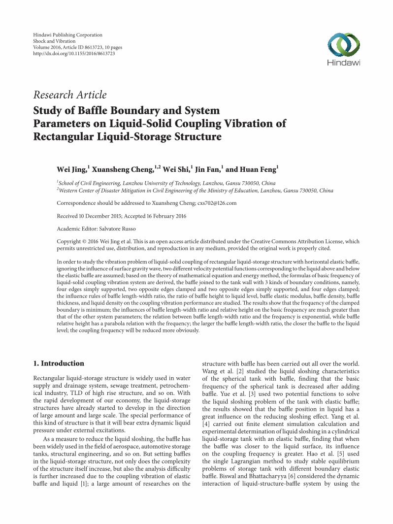
421 Effect of Baffle Length-Width Ratio on the Basic Fre-quency of Liquid-SolidCouplingVibration Theratios of bafflelength to width 120582 (120582 = 119887119886) are respectively 10 15 2025 and 30 baffle thickness 119889 is 6 cm the ratio of baffleheight to liquid level 120574 (120574 = 119867ℎ) is 05 liquid density 120588
119908
is 1000 kgm3 baffle density 120588 is 2500 kgm3 baffle elasticmodulus 119864 is 30GPa and the influence of 120582 on the basicfrequency of the coupling vibration is shown in Figure 3As can be seen from Figure 3 the natural frequencies ofthe coupling system under the three boundary conditionsare decreased with the increase of baffle length-width ratioand the relationship between length-width ratio and thenatural frequency is exponential Under the same length-width ratio natural frequency corresponding to four edgesof baffle simply supported is maximum natural frequencycorresponding to two opposite edges simply supported andtwo opposite edges clamped is middle and natural frequencycorresponding to four edges clamped is minimum namelythe basic frequency of the coupling system decreases with thestrengthening of the baffle constraint Therefore horizontalbaffle should be connected to tank wall with four clampededges when conducting sloshing reduction design it not only
Shock and Vibration 7
260
270
280
290
300
310
320
10 12 14 16 18 20 22 24 26 28 30
Four edges simply supportedTwo opposite edges clamped and twoopposite edges simply supportedFour edges clamped
Basic
freq
uenc
y12059611
(radmiddotsminus
1)
120582
Figure 3 Effect of baffle length-width ratio 120582 on the basic frequencyof liquid-solid coupling vibration
is convenient for construction but also can reduce the basicfrequency of fluid-solid coupling vibration
422 Effect of Baffle Height-Liquid Level Ratio on the BasicFrequency of Liquid-Solid Coupling Vibration The ratios ofbaffle height to liquid level 120574 (120574 = 119867ℎ) are respectively01 02 03 04 05 07 08 and 09 baffle length-widthratio 120582 is 10 baffle thickness 119889 is 6 cm liquid density 120588
119908
is 1000 kgm3 baffle density 120588 is 2500 kgm3 baffle elasticmodulus 119864 is 30GPa and the influence of 120574 on the basicfrequency of the coupling vibration is shown in Figure 4Figure 4 shows that the basic frequency of the couplingvibration under the three boundary conditions decreaseswith the increase of baffle height to liquid level ratio whenthe ratio 120574 changes in the range of 01sim05 the basic frequencyreduces relatively slow but when 120574 changes from 05 to 09that is the baffle is closer to the liquid surface the trendthat frequency decreases is much faster therefore in theactual project baffle should be designed as far as possiblenear to the liquid surface When the ratio 120574 is smallerthe basic frequency corresponding to the three boundaryconditions has a certain difference namely basic frequencycorresponding to four edges simply supported is maximumbasic frequency corresponding to two opposite edges simplysupported and two opposite edges clamped is middle andbasic frequency corresponding to four edges clamped isminimum but with the increase of 120574 the influence of baffleboundary conditions on the basic frequency of the couplingvibration is gradually weakened when the baffle position isclose to the liquid level the frequency corresponding to threekinds of boundary conditions is basically equivalent On thewhole the relationship between coupling vibration frequencyand the ratio 120574 is parabola
180
200
220
240
260
280
300
320
340
01 02 03 04 05 06 07 08 09
Four edges simply supportedTwo opposite edges clamped and twoopposite edges simply supportedFour edges clamped
Basic
freq
uenc
y12059611
(radmiddotsminus
1)
120574
Figure 4 Effect of baffle height to liquid level ratio 120574 on the basicfrequency of liquid-solid coupling vibration
318
319
320
321
322
6 8d (cm)
10 12
Four edges simply supportedTwo opposite edges clamped and twoopposite edges simply supportedFour edges clamped
Basic
freq
uenc
y12059611
(radmiddotsminus
1)
Figure 5 Effect of baffle thickness on the basic frequency of liquid-solid coupling vibration
423 Effect of Baffle Thickness on the Basic Frequency ofLiquid-Solid Coupling Vibration The baffle thickness 119889 isrespectively 6 cm 8 cm 10 cm and 12 cm in these cases therelative baffle thickness 119889119886 is in the scope of elastic thinplate the ratios 120582 and 120574 are 10 and 05 120588 is 2500 kgm3 120588
119908is
1000 kgm3 119864 is 30GPa and the influence of 119889 on the basicfrequency of the coupling vibration is shown in Figure 5 Ascan be seen from Figure 5 the basic frequencies correspond-ing to the three boundary conditions all decrease with theincrease of baffle thickness 119889 but with the increase of 119889 thetrend that frequencies decrease becomesmuch gentlerWhenthe baffle thickness is much thinner the difference of thefrequency corresponding to the three boundary conditions is
8 Shock and Vibration
319
320
321
322
323
324
22 24 26 28 30 32 34E (GPa)
Four edges simply supportedTwo opposite edges clamped and twoopposite edges simply supportedFour edges clamped
Basic
freq
uenc
y12059611
(radmiddotsminus
1)
Figure 6 Effect of bafflemodulus of elasticity on the basic frequencyof liquid-solid coupling vibration
relatively larger but with the increase of baffle thickness theinfluence of boundary conditions on the basic frequency ofthe coupling vibration is gradually weakened
424 Effect of Baffle ElasticModulus on the Basic Frequency ofLiquid-Solid Coupling Vibration The baffle elastic modulus119864 is respectively 22GPa 255 GPa 28GPa 30GPa 315 GPaand 325GPa 120588 is 2500 kgm3 119889 is 6 cm the ratios 120582 and 120574are 10 and 05 120588
119908is 1000 kgm3 and the influence of119864 on the
basic frequency of the coupling vibration is shown in Figure 6The results show that when the elastic modulus 119864 changes inthe process of small to large value the frequency of simplysupported edges is obviously larger than that of the othertwo kinds of boundary conditions and the basic vibrationfrequency decreases with the increase of elastic modulusso in the design of reinforced concrete rectangular liquid-storage structure in order to reduce the coupling vibrationfrequency higher grade concrete can be used for baffle
425 Effect of Baffle Density on the Basic Frequency of Liquid-Solid Coupling Vibration The baffle density 120588 is respec-tively 2100 kgm3 2200 kgm3 2300 kgm3 2400 kgm32500 kgm3 and 2600 kgm3 d is 6 cm the ratios 120582 and 120574 are10 and 05 120588
119908is 1000 kgm3 119864 is 30GPa and the influence
of 120588 on the basic frequency of the coupling vibration is shownin Figure 7 As can be seen from Figure 7 the effect of baffledensity on basic frequency of the coupling system is verysmall therefore the influence of baffle density on the basicfrequency cannot be considered in the design
426 Effect of LiquidDensity on the Basic Frequency of Liquid-Solid Coupling Vibration The liquid density 120588
119908is respec-
tively 800 kgm3 900 kgm3 1000 kgm3 and 1100 kgm3 dis 6 cm the ratios 120582 and 120574 are 10 and 05 120588 is 2500 kgm3E is 30GPa and the influence of 120588
119908on the basic frequency
of the coupling vibration is shown in Figure 8 As can be
319
320
321
322
2100 2200 2300 2400 2500 2600
Four edges simply supportedTwo opposite edges clamped and twoopposite edges simply supportedFour edges clamped
120588 (kgmiddotmminus3)
Basic
freq
uenc
y12059611
(sminus1)
Figure 7 Effect of baffle density on the basic frequency of liquid-solid coupling vibration
319
320
321
322
323
8 9 10 11
Four edges simply supportedTwo opposite edges clamped and twoopposite edges simply supportedFour edges clamped
Basic
freq
uenc
y12059611
(radmiddotsminus
1)
120588w (kNmiddotmminus3)
Figure 8 Effect of liquid density on the basic frequency of liquid-solid coupling vibration
seen from Figure 8 the basic frequencies of the couplingvibration corresponding to the three boundary conditionsall increase slowly with the increase of liquid density Undervarious liquid densities the frequency of simply supportededges is larger than that of the other two kinds of boundaryconditions compared with other parameters of the systemliquid density is positively correlated with basic frequencybut in the actual engineering the difference of liquid densityis small in general so the effect of liquid density on the basicfrequency also cannot be considered
43 Solution of Coupled Modes The results gotten fromSection 42 show that the coupling vibration frequencies areaffected by the parameters 120582 and 120574 significantly more thanthe other system parameters due to limited space the modes
Shock and Vibration 9
120582 = 12 120582 = 16
(a)
120582 = 20 120582 = 24
(b)
Figure 9 Coupled modes corresponding to 120582
120574 = 03 120574 = 05
(a)
120574 = 07 120574 = 09
(b)
Figure 10 Coupled modes corresponding to 120574
corresponding to 120582 (12 16 20 24) and 120574 (05 05 07 09)are listed in Figures 9 and 10
5 Conclusions
(1) The influence of baffle boundary conditions on the basicfrequency of the coupling vibration of rectangular liquid-storage structure cannot be ignored In general under thesame conditions the basic frequency of the coupling vibra-tion corresponding to four edges of baffle simply supportedis maximum frequency corresponding to two opposite edges
simply supported and two opposite edges clamped is middleand frequency corresponding to four edges clamped is min-imum Therefore horizontal baffle should be connected totank wall with four clamped edges when conducting sloshingreduction design it not only is convenient for constructionbut also can reduce the basic frequency of fluid-solid couplingvibration
(2) Many of system parameters have a negative relationwith the basic frequency such as baffle elastic modulus bafflethickness baffle length-width ratio and the ratio of baffleheight to liquid level while the liquid density is positivelycorrelated with the basic frequency of the coupling vibrationbut in the actual engineering the difference of liquid densityis small in general so the effect of liquid density on the basicfrequency of the coupling vibration cannot be consideredBesides the effect of baffle density on the coupling frequencyis very small and its effect can also be neglected
(3) In contrast the influences of length-width ratio andbaffle height relative to liquid level on the basic frequencyof the coupling vibration are much greater than that of theother system parameters the larger the baffle length-widthratio the closer the position of horizontal baffle to the liquidlevel the coupling frequency will be reduced more obviouslyand the relation between baffle length-width ratio and thecoupling vibration frequency is exponential while the ratioof baffle height to liquid lever has a parabola relation with thecoupling vibration frequency
Competing Interests
The authors declare that there are no competing interestsregarding the publication of this paper
Acknowledgments
This paper is a part of the support of the National Natural Sci-ence Foundation of China (Grant nos 51368039 51478212) apart of the support of the Education Ministry Doctoral TutorFoundation of China (Grant no 20136201110003) a part ofthe support of the Plan Project of Science and Technology inGansu Province (Grant no 144GKCA032) and a part of thesupport of theNational Key Basic Research andDevelopmentPlan of China (973 Plan Grant no 2011CB013600)
References
[1] X D Cheng ldquoEquivalent mechanical model of liquid sloshingin a cylindrical tank with elastic platerdquo Journal of AnqingTeachers College (Natural Science Edition) vol 4 no 1 pp 37ndash40 1998
[2] Z L Wang X D Cheng and B Quan ldquoLiquid sloshing inspherical tank with space at low gravity environmentrdquo ChineseJournal of space Science vol 10 no 2 pp 107ndash119 1990
[3] B Z Yue Z L Wang J F Li and J L Kuang ldquoLiquid sloshingin cylindrical tank with elastic spacerrdquo Journal of TsinghuaUniversity (Science and Technology) vol 37 no 8 pp 26ndash281997
[4] M Yang J F Li T S Wang and W Wang ldquoDeterminationof damping ratio of the small-amplitude liquid sloshing within
10 Shock and Vibration
the cylindrical container with a ring bafflerdquo Chinese Journal ofTheoretical and Applied Mechanics vol 38 no 5 pp 660ndash6672006
[5] Y J Hao Y Yang and X Z Bai ldquoAnalysis of deformation andstress of elastic plate in a tank under the influence of fluidrdquoJournal of Mechanical Strength vol 31 no 2 pp 250ndash255 2009
[6] K C Biswal and S K Bhattacharyya ldquoDynamic response ofstructure coupled with liquid sloshing in a laminated compositecylindrical tank with bafflerdquo Finite Elements in Analysis andDesign vol 46 no 11 pp 966ndash981 2010
[7] M Shahrokhi F RostamiM AM Said and Syafalni ldquoNumer-ical modeling of baffle location effects on the flow pattern ofprimary sedimentation tanksrdquoAppliedMathematicalModellingvol 37 no 6 pp 4486ndash4496 2013
[8] J DWang D Zhou andWQ Liu ldquoStudy of coupling vibrationcharacteristics of a cylindrical tankwith a flexible annual bafflerdquoEngineering Mechanics vol 29 no 6 pp 270ndash276 2012
[9] W-H Song D-Z Ning Y-L Liu and T Bing ldquoNumericalsimulation of liquid sloshing in a containerwith bafflesrdquoChineseJournal of Hydrodynamics vol 27 no 1 pp 54ndash61 2012
[10] M-A Xue J H Zheng and P Lin ldquoNumerical simulationof sloshing phenomena in cubic tank with multiple bafflesrdquoJournal of Applied Mathematics vol 2012 Article ID 245702 21pages 2012
[11] J DWang D Zhou andWQ Liu ldquoStudy on coupled vibrationcharacteristics of a cylindrical container with multiple elasticannular bafflesrdquo Science China Technological Sciences vol 55no 12 pp 3292ndash3301 2012
[12] S M Hasheminejad M M Mohammadi and M JarrahildquoLiquid sloshing in partly-filled laterally-excited circular tanksequipped with bafflesrdquo Journal of Fluids and Structures vol 44pp 97ndash114 2014
[13] M R Shekari ldquoSeismic response of liquid-filled tank withbafflesrdquo Journal of Marine Science and Application vol 13 no3 pp 299ndash304 2014
[14] M Ebrahimian M A Noorian and H Haddadpour ldquoFreevibration sloshing analysis in axisymmetric baffled containersunder low-gravity conditionrdquoMicrogravity Science and Technol-ogy vol 27 no 2 pp 97ndash106 2015
[15] M A Goudarzi and P Farshadmanesh ldquoNumerical evaluationof hydrodynamic damping due to the upper mounted bafflesin real scale tanksrdquo Soil Dynamics and Earthquake Engineeringvol 77 pp 290ndash298 2015
[16] X-S Cheng and Y-F Du ldquoThe dynamic fluid pressure ofreinforced concrete rectangular liquid-storage tankswith elasticwallsrdquo Engineering Mechanics vol 26 no 6 pp 82ndash88 2009
[17] Z LWang andBQuan ldquoSloshing of liquid in the spherical tankwith spaces of netted-holesrdquo Chinese Journal of space Sciencevol 9 no 2 pp 136ndash147 1989
[18] X D Cheng and Z L Wang ldquoHydroelastic vibrations inrectangular tank with elastic spacerrdquoMechanics in Engineeringvol 21 pp 50ndash52 1999
[19] N RMo Engineering FluidMechanics Huazhong University ofScience and Technology Press Wuhan China 2003 (Chinese)
[20] T Y Tsui and N C Small ldquoHydroelastic oscillations of a liquidsurface in an annular circular cylindrical tank with flexiblebottomrdquo Journal of Spacecraft amp Rockets vol 2 no 2 pp 202ndash206 1968
[21] X S Cheng and Y F Du ldquoLiquid-solid coupling sloshingof reinforced concrete rectangular liquid-storage tanks-elasticsoleplaterdquo Chinese Journal of Applied Mechanics vol 25 no 4pp 622ndash626 2008
[22] S L Ding and W G Bao ldquoModal analysis and equivalentmechanical model of liquid sloshing in arbitrary 3D containerrdquoChinese Quarterly of Mechanics vol 25 no 1 pp 62ndash68 2004
[23] Z J Zou ldquoHorizontal aseismatic calculation of a multi-story structure with large sewage poolsrdquo Chinese Quarterly ofMechanics vol 24 no 1 pp 120ndash123 2003
International Journal of
AerospaceEngineeringHindawi Publishing Corporationhttpwwwhindawicom Volume 2014
RoboticsJournal of
Hindawi Publishing Corporationhttpwwwhindawicom Volume 2014
Hindawi Publishing Corporationhttpwwwhindawicom Volume 2014
Active and Passive Electronic Components
Control Scienceand Engineering
Journal of
Hindawi Publishing Corporationhttpwwwhindawicom Volume 2014
International Journal of
RotatingMachinery
Hindawi Publishing Corporationhttpwwwhindawicom Volume 2014
Hindawi Publishing Corporation httpwwwhindawicom
Journal ofEngineeringVolume 2014
Submit your manuscripts athttpwwwhindawicom
VLSI Design
Hindawi Publishing Corporationhttpwwwhindawicom Volume 2014
Hindawi Publishing Corporationhttpwwwhindawicom Volume 2014
Shock and Vibration
Hindawi Publishing Corporationhttpwwwhindawicom Volume 2014
Civil EngineeringAdvances in
Acoustics and VibrationAdvances in
Hindawi Publishing Corporationhttpwwwhindawicom Volume 2014
Hindawi Publishing Corporationhttpwwwhindawicom Volume 2014
Electrical and Computer Engineering
Journal of
Advances inOptoElectronics
Hindawi Publishing Corporation httpwwwhindawicom
Volume 2014
The Scientific World JournalHindawi Publishing Corporation httpwwwhindawicom Volume 2014
SensorsJournal of
Hindawi Publishing Corporationhttpwwwhindawicom Volume 2014
Modelling amp Simulation in EngineeringHindawi Publishing Corporation httpwwwhindawicom Volume 2014
Hindawi Publishing Corporationhttpwwwhindawicom Volume 2014
Chemical EngineeringInternational Journal of Antennas and
Propagation
International Journal of
Hindawi Publishing Corporationhttpwwwhindawicom Volume 2014
Hindawi Publishing Corporationhttpwwwhindawicom Volume 2014
Navigation and Observation
International Journal of
Hindawi Publishing Corporationhttpwwwhindawicom Volume 2014
DistributedSensor Networks
International Journal of

2 Shock and Vibration
finite elementmethod and studied the influences of baffle sizeand position on the liquid sloshing and structural responseShahrokhi et al [7] studied the influences of baffle positionon the liquid flow pattern of liquid-storage structure by usingcomputational fluid dynamics (CFD) Wang et al [8] got thepotential functions of each subdomain liquid by using theseparation variable method and superposition principle andstudied the fluid-solid coupling characteristics of the liquid-storage structure with elastic baffle Song et al [9] establisheda mathematical model of water free surface by using theboundary element method in order to solve the problem ofliquid sloshing in a rectangular tank with baffle and pointedout that the reducing sloshing function of baffle is mainlyachieved by changing the frequency distribution of originalliquid-storage structure Xue et al [10] simulated a cubeliquid-storage structure with multibaffles and got the con-clusion that baffle can effectively reduce the amplitude anddynamic liquid pressure of liquid sloshing Wang et al [11]divided the fluid domain into several simple subdomains andthe influences of location inner radius and the number ofcircular baffles on the coupling vibration of the liquid-storagestructure were studied Hasheminejad et al [12] studied thetransient horizontal response of the tank with baffle andthe effective baffle shape that can suppress the lateral forceShekari [13] divided the fluid domain into two parts withbaffle using boundary element method to study the basicmode of liquid-storage structure with baffle summarizingthe maximum seismic responses of the structure with bafflethen the baffle effect on the vibration control of liquid-storage structure is proved Ebrahimian et al [14] appliedthe feature analysis method to study the basic frequency andformation of liquid-storage structure with baffle Goudarziand Farshadmanesh [15] studied the free vibration of liquid-storage structure with different size and different positionbaffle the results showed that the liquid sloshing height wasreduced by 50 owing to adding baffle
In summary although the baffle can exert an inhibitoryeffect on the liquid sloshing of liquid-storage structure itseffect on the fluid-solid coupling vibration is influenced bymany factors So the effect of elastic horizontal baffle on thefluid-solid coupling vibration of rectangular liquid-storagestructure will be studied further in this paper supposing theliquid is of no rotation of no viscosity and incompressiblebecause the occurrence probability of gravity wave in thestructure of civil engineering is small [16] therefore thesurface gravity wave is ignored Assuming that the wallof liquid-storage structure is rigid and its baffle is elastictwo different velocity potential functions corresponding tothe liquid above and below the elastic baffle are definedbased on the theory of mathematical equation and energymethod the formulas of basic frequency of liquid-solid cou-pling vibration of rectangular storage structure with flexiblebaffle are derived the baffle joined to the tank wall with3 kinds of boundary conditions namely four edges simplysupported two opposite edges clamped and two oppositeedges simply supported and four edges clamped the con-clusions can provide theoretical basis for the reducing slosh-ing design of reinforced concrete rectangular liquid-storagestructure
2 Fluid-Solid Coupling Modeland Basic Theory
Assuming that the liquid is in an ideal state the length widthand height of the rectangular liquid-storage structure are 119886 119887and 119888 respectively the distance between elastic baffle and thetank bottom is 119867 liquid level height is ℎ and ℎ is greaterthan119867 supposing the wall is rigid liquid sloshing is of smallamplitude Ignoring hollows in the elastic baffle although inpractical engineering application in order to make the liquidflow through the baffle some holes need to be set in the baffleif the holes are small and arranged in centralized mannertheir effect on the coupling vibration can be ignored whenthe holes layout does not conform to the above provisionsthe calculation results should be modified by considering theliquid flow effect caused by baffle holes [17] the analyticalmodel is shown in Figure 1
When the liquid sloshing is of small amplitude linearpotential flow theory can be used to solve the couplingvibration problem Assuming that the baffle is located belowthe stationary liquid level in this case the velocity potentialsfor both sides of liquid of the baffle can be expressed as1206011(119909 119910 119911 119905) and120601
2(119909 119910 119911 119905) 120601
1and1206012all satisfy the Laplace
equation [18]
nabla2120601119895= 0 119895 = 1 2 (1)
According to the existing literature [19] for commonliquids because 120590120588
119908is small for simplicity liquid surface
tension 120590 can be ignored After neglecting the surface tensionof liquid sloshing the kinematic and dynamic boundaryconditions for the first-order liquid sloshing problem can beexpressed as follows
12059721206011
1205971199052+ 119892
1205971206011
120597119911
100381610038161003816100381610038161003816100381610038161003816119911=ℎ
= 0 (2)
where 119892 is the gravity accelerationOn the contact surface of rigid wall and liquid the liquid
velocity potential functions satisfy the following boundaryconditions
120597120601119895
120597119909
100381610038161003816100381610038161003816100381610038161003816119909=0119886
= 0
120597120601119895
120597119910
100381610038161003816100381610038161003816100381610038161003816119910=0119887
= 0
119895 = 1 2
(3)
1205971206012
120597119911
10038161003816100381610038161003816100381610038161003816119911=0
= 0 (4)
According to Bernoulli equation the relation betweenliquid sloshing pressure and velocity potential is 119875 =
minus120588119908(120597120601120597119905) thus the total sloshing pressure of the baffle
under the action of upper and lower liquid is as follows
119875119867= (minus120588
119908
1205971206011
120597119905
) minus (minus120588119908
1205971206012
120597119905
) (5)
Shock and Vibration 3
a
h
H
x
c
z
Liquid
Liquid
Baffle
(a) Facade model
y
x
b
a
(b) Plane model
Figure 1 Analytical model of liquid-storage structure
where 120588119908is liquid density and 119875
119867 is total liquid sloshingpressure
Supposing the deflection in the point (119909 119910119867) is119882(119909 119910 119905) then the differential equation of baffle vibration is
nabla4119882(119909 119910 119905) +
120588
119863
1205972119882(119909 119910 119905)
1205971199052
= minus
119875119867
119863
(6)
where119863 is the baffle flexural rigidity119863 = 1198641198893[12(1 minus ])] 120588
is baffle density 119889 is baffle thickness and ] is Poissonrsquos ratioOn the contact surface of liquid and baffle the velocities
in the 119911 direction should be equal to each other namely
1205971206011
120597119911
=
1205971206012
120597119911
=
120597119882
120597119905
10038161003816100381610038161003816100381610038161003816119911=119867
(7)
3 Coupling Vibration Solution ofLiquid-Storage Structure with Baffle
31 Coupled Frequency Using the method of separation ofvariables the velocity potential functions that satisfy (1) and(3) can be expressed as [3 20 21]
1206011= 119860119898119899
cos(119898120587119886
119909) cos(119899120587119887
119910) (119890minus119870119898119899119911+ 119861119898119899119890119870119898119899119911)
sdot 119890119894120596119898119899119905
1206012= 119862119898119899
cos(119898120587119886
119909) cos(119899120587119887
119910) (119890minus119870119898119899119911+ 119863119898119899119890119870119898119899119911)
sdot 119890119894120596119898119899119905
(8)
where 119870119898119899
= radic(119898120587119886)2+ (119899120587119887)
2 (119898 119899 = 1 2 ) 120596119898119899
isthe basic frequency of the coupling system
Considering that the liquid sloshing is of small amplitudein the free liquid surface 119911 is equal to ℎ approximately taking(8) into (2) and (4) into (7) we can get
119861119898119899
=
(119892119870119898119899
+ 1205962
119898119899) 119890minus119870119898119899ℎ
(119892119870119898119899
minus 1205962
119898119899) 119890119870119898119899ℎ (9)
119863119898119899
= 1 (10)
119862119898119899
=
119860119898119899
(119861119898119899119890119870119898119899119867minus 119890minus119870119898119899119867)
119890119870119898119899119867minus 119890minus119870119898119899119867
(11)
Taking (8) (9) (10) and (11) into (5) the liquid dynamicpressure acting on the baffle can be obtained
119875119867= minus120588119894120596
119898119899cos(119898120587
119886
119909) cos(119899120587119887
)
sdot 119860119898119899
(119890minus119870119898119899119867+ 119861119898119899119890119870119898119899119867)
sdot [1 minus cth (119870119898119899119867)
119861119898119899119890119870119898119899119867minus 119890minus119870119898119899119867
119861119898119899119890119870119898119899119867+ 119890minus119870119898119899119867] 119890119894120596119898119899119905
(12)
Assume that the deflection of elastic baffle is [20 21]
119882(119909 119910 119905) = 119882119898119899
(119909 119910) 119890119894120596119898119899119905 (13)
By (6) (12) and (13) the following equation can beobtained
119863nabla4119882119898119899
minus 1205881198981198991205962
119898119899119882119898119899
= 0 (14)
4 Shock and Vibration
where 120588119898119899
is a function of 120596119898119899 it can be called dynamic
density [21] and
120588119898119899
= 120588
minus
120588119908
119870119898119899
[
119861119898119899119890119870119898119899119867+ 119890minus119870119898119899119867
119861119898119899119890119870119898119899119867minus 119890minus119870119898119899119867minus cth (119870
119898119899119867)]
(15)
By (14) the maximum kinetic energy 119879max and thepotential energy 119881max of the elastic baffle can be obtainedrespectively
119879max =1
2
1205881198981198991205962
119898119899int
119886
0
int
119887
0
1198822
119898119899(119909 119910) 119889119909 119889119910
119881max =1
2
119863int
119886
0
int
119887
0
(
1205972119882119898119899
1205971199092
+
1205972119882119898119899
1205971199102
)
2
minus 2 (1 minus ])
sdot [
1205972119882119898119899
1205971199092
sdot
1205972119882119898119899
1205971199102
minus (
1205972119882
120597119909120597119910
)
2
]119889119909119889119910
(16)
According to the law of energy conservation
119881max = 119879max (17)
Taking (16) into (17) then
1205962
119898119899
120588119898119899
119863
= 119889119898119899 (18)
where
119889119898119899
=
int
119886
0int
119887
0(12059721198821198981198991205971199092+ 12059721198821198981198991205971199092)
2
minus 2 (1 minus ]) sdot [(12059721198821198981198991205971199092) sdot (12059721198821198981198991205971199092) minus (120597
2119882119898119899120597119909120597119910)] 119889119909 119889119910
int
119886
0int
119887
01198822
119898119899119889119909 119889119910
(19)
Taking (9) and 120588119898119899
of (14) into (18)
1198861198981198991205964
119898119899minus 1198871198981198991205962
119898119899+ 119888119898119899
= 0 (20)
where
119886119898119899
= [120588119870119898119899
+ 120588119908cth (119870
119898119899119867)] ch [119870
119898119899(ℎ minus 119867)]
+ 120588119908sh [119870119898119899
(ℎ minus 119867)]
119887119898119899
= 119892119870119898119899
120588119870119898119899sh [119870119898119899
(ℎ minus 119867)] + 120588119908cth (119870
119898119899119867)
sdot sh [119870119898119899
(ℎ minus 119867)] + 120588119908cth [119870
119898119899(ℎ minus 119867)]
+ 119863119889119898119899119870119898119899ch [119870119898119899
(ℎ minus 119867)]
119888119898119899
= 1198631198891198981198991198702
119898119899119892sh [119870
119898119899(ℎ minus 119867)]
(21)
The basic frequency of the coupling system can beobtained by solving (20)
1205962
119898119899=
119887119898119899
minus radic1198872
119898119899minus 4119886119898119899119888119898119899
2119886119898119899
(22)
As can be seen from (18) in order to obtain the basicfrequency of the coupled vibration the dynamic density 120588
119898119899
and 119889119898119899
must be known firstly through the above analysisthe liquid dynamic density 120588
119898119899has been obtained it can be
seen that the parameters such as liquid height horizontalbaffle height and baffle size have a great influence on 120588
119898119899
The main factor affecting the expression of 119889119898119899
of elasticbaffle is the boundary conditions Based on the existingresearch the paper derives the expression of 119889
119898119899of liquid-
storage structure with baffle and the baffle joined to thetank wall with 3 kinds of boundary conditions namely four
edges simply supported two opposite edges clamped and twoopposite edges simply supported and four edges clamped bydoing this the basic frequency of the coupling vibration of therectangular liquid-storage structure with elastic baffle can besolved
(1) Four Edges of Baffle Simply Supported For baffle withfour edges simply supported its boundary conditions are asfollows
119882|119909=0119886= 0
119882|119910=0119887= 0
(23)
Considering the boundary conditions that (23) satisfieswe can set
119882119898119899
(119909 119910) = sin 119898120587119909
119886
sin119898120587119910
119887
(24)
Taking (24) into the expression of 119889119898119899
of (18) gets thefollowing equation
119889119898119899
= 1205874(
1198982
1198862+
1198992
1198872)
2
(25)
(2) Two Opposite Edges of Baffle Clamped and Two OppositeEdges of Baffle Simply Supported For two opposite edgesof baffle clamped and two opposite edges of baffle simplysupported the boundary conditions are as follows
119882|119909=0119886= 0
120597119882
120597119909
10038161003816100381610038161003816100381610038161003816119909=0119886
= 0
119882|119910=0119887= 0
(26)
Shock and Vibration 5
For two opposite edges of baffle clamped and two oppo-site edges of baffle simply supported the deflection equationshould satisfy (26) we can suppose
119882119898119899
(119909 119910) = (1 minus cos2119898120587119909119886
) sin119899120587119910
119887
(27)
Taking (27) into the expression of 119889119898119899
of (18) we can get
119889119898119899
=
1
3
(
2119898120587
119886
)
4
+ (
119899120587
119887
)
4
+
2
3
(
2119898120587
119886
)
2
(
119899120587
119887
)
2
(28)
(3) Four Edges of Baffle Clamped For bafflewith four clampededges it has the following boundary conditions
119882|119909=0119886= 0
120597119882
120597119909
10038161003816100381610038161003816100381610038161003816119909=0119886
= 0
119882|119910=0119887= 0
120597119882
120597119909
10038161003816100381610038161003816100381610038161003816119910=0119887
= 0
(29)
Considering boundary conditions equations (29) for arectangular baffle with four clamped edges the baffle deflec-tion equation can be expressed as
119882119898119899
(119909 119910) = (1 minus cos 2119898120587119909119886
) (1 minus cos2119898120587119910
119887
) (30)
Taking (30) into the expression of 119889119898119899
of (18) then119889119898119899
=
1
3
[(
2119898120587
119886
)
4
+ (
2119899120587
119887
)
4
+
2
3
(
2119898120587
119886
)
2
(
2119899120587
119887
)
2
]
(31)
Through the above derivation as can be seen from (20)and (22) the main factors affecting the basic frequency ofthe coupling vibration of rectangular liquid-storage structurewith baffle include liquid density baffle density baffle thick-ness the ratio of baffle height to liquid level the ratio ofbaffle length to width and baffle boundary conditions Forconvenience of engineering application supposing the ratioof baffle length to width is 120582 = 119887119886 and the ratio of baffleheight to liquid level is 120574 = 119867ℎ and taking 119898 = 119899 = 1then the fundamental frequency of the coupling system canbe gotten by (22)
1205962
11=
11988711minus radic1198872
11minus 41198861111988811
211988611
(32)
where11988711= 1198921198701112058811987011sh [11987011(ℎ minus 119867)] + 120588
119908cth (119870
11119867)
sdot sh [11987011(ℎ minus 119867)] + 120588
119908cth [119870
11(ℎ minus 119867)]
+ 1198631198891111987011ch [11987011(ℎ minus 119867)]
11988811= 119863119889111198702
11119892sh [119870
11(ℎ minus 119867)]
11987011=
120587
119886
radic1 +
1
1205822
(33)
32 Theory of Coupled Modes In order to solve the coupledmodes corresponding to the basic coupled frequency ofliquid-storage structure with horizontal elastic baffle we canassume (34) based on (8)
120601119895= Φ119895(119909 119910 119911) 119890
119894120596119898119899119905 (119895 = 1 2) (34)
Taking (34) into continuity equation (1) of liquid sloshingin the fluid domain 119881 (2) of kinematic and dynamic bound-ary conditions of liquid free surface 120597119878
119891 boundary condition
equations (3) and (4) in the liquid-solid interaction wall 120597119878119908
and same speed condition equation (7) in the baffle (119911 = 119867)respectively then the differential boundary value equation ofcharacteristic mode function can be obtained
nabla2Φ119895= 0 (119895 = 1 2) 119881
120597Φ1
120597119911
=
1205962
119898119899
119892
Φ1 120597119878
119891
120597Φ119895
120597119909
=
120597Φ119895
120597119910
=
120597Φ2
120597119911
= 0 120597119878119908
120597Φ1
120597119911
=
120597Φ2
120597119911
=
120597119882
120597119905
= 0 119911 = 119867
(35)
Equation (35) can be solved by FEM method andthe equation should be firstly transformed into functionalextremes problem
120575119871 (Φ) = 0 (36)
where 119871 is the functional its expression is [22]
119871 = int
119881
[(
120597Φ
120597119909
)
2
+ (
120597Φ
120597119910
)
2
+ (
120597Φ
120597119911
)
2
]119889119881
minus
1205962
119898119899
119892
int
120597119878119891
Φ2
119895119889119878
(37)
After the finite element discretization of the liquid Φ ofeach element 119881
119890can be obtained by interpolation method
[23]
Φ(119909 119910 119911) = sum
119896=1
119873119896Φ119890
119896= N119879Φ
119890 (38)
where N = (1198731 1198732 119873
119895)119879 is shape function array in
the fluid domain and Φ119890
= (Φ1198901 Φ1198902 Φ
119890119896) is the
corresponding node arraySimilarlyΦ of each element 119878
119891119890in the free surface can be
expressed as
Φ(119909 119910 119911) = sum
119897=1
119897Φ119890
119897= N119879Φ
119890 (39)
where N = (1 2
119897) is shape function array in the
free surface andΦ119890= (Φ1198901 Φ1198902 Φ
119890119897) is the corresponding
node arrayTaking (38) and (39) into 119871
119871 = sumΦ119879
119890C119890Φ119890minus
1205962
119898119899
119892
sumΦ119879
119890D119890Φ119890
= Φ119879CΦ minus
1205962
119898119899
119892
Φ119879DΦ
(40)
6 Shock and Vibration
whereC andD are formed by element matrixesC119890andD
119890Φ
is integrated node variable array and
C119890= sum
119881119890
(
120597N120597119909
120597N119879
120597119909
+
120597N120597119910
120597N119879
120597119910
+
120597N120597119911
120597N119879
120597119911
)119889119881
D119890= int
119878119891119890
NN119879119889119878119891
(41)
Taking (40) into (36)
CΦ minus1205962
119898119899
119892
DΦ = 0 (42)
4 Numerical Examples and Discussions
According to (32) the basic frequency of the liquid-solidcoupling vibration of rectangular liquid-storage structurewith horizontal baffle can be solved in order to study thecoupling vibration characteristics of solid-liquid couplingsystem more comprehensively assuming the baffle joined tothe tank wall with 3 kinds of boundary conditions taking avariety of values for the main system parameters of this kindof structure by doing this statistical results can be obtainedThe liquid height ℎ is 3m the baffle width is 4m and theother parameters are as follows
41 Verification of Proposed Method Equation (22) is thebasic frequency of three-dimensional coupling system con-sidering the elasticity of horizontal baffle when the baffleis assumed to be rigid namely baffle bending stiffness 119863tends to infinity the fluid-solid coupling vibration in theupper baffle can be approximately equivalent to liquid-storage structure without baffle and the liquid couplingfrequency above the rigid baffle with four clamped edges canbe obtained by (22)
120596119898119899
= radic119892radic(
119898120587
119886
)
2
+ (
119899120587
119887
)
2
sdot th[
[
radic(
119898120587
119886
)
2
+ (
119899120587
119887
)
2
sdot (ℎ minus 119867)]
]
(43)
For the two-dimensional rectangular liquid-storagestructure the coupling frequency can be expressed as [23]
120596119899= radic
119892119899120587
119887
th(119899120587 (ℎ minus 119867)
119887
) (44)
By comparing (43) and (44) of basic coupling frequencyin the three- and two-dimensional coupling vibration prob-lem the calculation method rationality of the couplingfrequency is explained to a certain extent
On the other hand in order to further verify the methodrationality of the coupling vibration of rectangular liquid-storage structure with different boundary baffle the corre-sponding calculation model is established by ADINA Bafflelength to width ratio 120582 is 10 baffle height-liquid level ratio120574 is 01 03 05 07 and 09 respectively baffle thickness 119889
16
19
22
25
28
31
34
01 03 05 07 09
Four edges simply supported
Four edges clampedFour edges simply supported
Four edges clamped
ADINA
Basic
freq
uenc
y12059611
(radmiddotsminus
1)
120574
Proposedmethod
Two edges clamped and twoedges simply supported
Two edges clamped and twoedges simply supported
Figure 2 Results comparison
is 6 cm baffle elastic modulus 119864 is 30GPa baffle density 120588 is2500 kgm3 and 120588
119908is 1000 kgm3 Comparison of calculation
results of ADINA and (32) is shown in Figure 2As seen from Figure 2 the difference of coupling fre-
quency results calculated by the proposed method andADINA is small besides with the change of 120574 changetrends of frequency corresponding to the two methodsare consistent then the validity of the present method isverified
42 Analysis of Boundary and Parameter Influence
421 Effect of Baffle Length-Width Ratio on the Basic Fre-quency of Liquid-SolidCouplingVibration Theratios of bafflelength to width 120582 (120582 = 119887119886) are respectively 10 15 2025 and 30 baffle thickness 119889 is 6 cm the ratio of baffleheight to liquid level 120574 (120574 = 119867ℎ) is 05 liquid density 120588
119908
is 1000 kgm3 baffle density 120588 is 2500 kgm3 baffle elasticmodulus 119864 is 30GPa and the influence of 120582 on the basicfrequency of the coupling vibration is shown in Figure 3As can be seen from Figure 3 the natural frequencies ofthe coupling system under the three boundary conditionsare decreased with the increase of baffle length-width ratioand the relationship between length-width ratio and thenatural frequency is exponential Under the same length-width ratio natural frequency corresponding to four edgesof baffle simply supported is maximum natural frequencycorresponding to two opposite edges simply supported andtwo opposite edges clamped is middle and natural frequencycorresponding to four edges clamped is minimum namelythe basic frequency of the coupling system decreases with thestrengthening of the baffle constraint Therefore horizontalbaffle should be connected to tank wall with four clampededges when conducting sloshing reduction design it not only
Shock and Vibration 7
260
270
280
290
300
310
320
10 12 14 16 18 20 22 24 26 28 30
Four edges simply supportedTwo opposite edges clamped and twoopposite edges simply supportedFour edges clamped
Basic
freq
uenc
y12059611
(radmiddotsminus
1)
120582
Figure 3 Effect of baffle length-width ratio 120582 on the basic frequencyof liquid-solid coupling vibration
is convenient for construction but also can reduce the basicfrequency of fluid-solid coupling vibration
422 Effect of Baffle Height-Liquid Level Ratio on the BasicFrequency of Liquid-Solid Coupling Vibration The ratios ofbaffle height to liquid level 120574 (120574 = 119867ℎ) are respectively01 02 03 04 05 07 08 and 09 baffle length-widthratio 120582 is 10 baffle thickness 119889 is 6 cm liquid density 120588
119908
is 1000 kgm3 baffle density 120588 is 2500 kgm3 baffle elasticmodulus 119864 is 30GPa and the influence of 120574 on the basicfrequency of the coupling vibration is shown in Figure 4Figure 4 shows that the basic frequency of the couplingvibration under the three boundary conditions decreaseswith the increase of baffle height to liquid level ratio whenthe ratio 120574 changes in the range of 01sim05 the basic frequencyreduces relatively slow but when 120574 changes from 05 to 09that is the baffle is closer to the liquid surface the trendthat frequency decreases is much faster therefore in theactual project baffle should be designed as far as possiblenear to the liquid surface When the ratio 120574 is smallerthe basic frequency corresponding to the three boundaryconditions has a certain difference namely basic frequencycorresponding to four edges simply supported is maximumbasic frequency corresponding to two opposite edges simplysupported and two opposite edges clamped is middle andbasic frequency corresponding to four edges clamped isminimum but with the increase of 120574 the influence of baffleboundary conditions on the basic frequency of the couplingvibration is gradually weakened when the baffle position isclose to the liquid level the frequency corresponding to threekinds of boundary conditions is basically equivalent On thewhole the relationship between coupling vibration frequencyand the ratio 120574 is parabola
180
200
220
240
260
280
300
320
340
01 02 03 04 05 06 07 08 09
Four edges simply supportedTwo opposite edges clamped and twoopposite edges simply supportedFour edges clamped
Basic
freq
uenc
y12059611
(radmiddotsminus
1)
120574
Figure 4 Effect of baffle height to liquid level ratio 120574 on the basicfrequency of liquid-solid coupling vibration
318
319
320
321
322
6 8d (cm)
10 12
Four edges simply supportedTwo opposite edges clamped and twoopposite edges simply supportedFour edges clamped
Basic
freq
uenc
y12059611
(radmiddotsminus
1)
Figure 5 Effect of baffle thickness on the basic frequency of liquid-solid coupling vibration
423 Effect of Baffle Thickness on the Basic Frequency ofLiquid-Solid Coupling Vibration The baffle thickness 119889 isrespectively 6 cm 8 cm 10 cm and 12 cm in these cases therelative baffle thickness 119889119886 is in the scope of elastic thinplate the ratios 120582 and 120574 are 10 and 05 120588 is 2500 kgm3 120588
119908is
1000 kgm3 119864 is 30GPa and the influence of 119889 on the basicfrequency of the coupling vibration is shown in Figure 5 Ascan be seen from Figure 5 the basic frequencies correspond-ing to the three boundary conditions all decrease with theincrease of baffle thickness 119889 but with the increase of 119889 thetrend that frequencies decrease becomesmuch gentlerWhenthe baffle thickness is much thinner the difference of thefrequency corresponding to the three boundary conditions is
8 Shock and Vibration
319
320
321
322
323
324
22 24 26 28 30 32 34E (GPa)
Four edges simply supportedTwo opposite edges clamped and twoopposite edges simply supportedFour edges clamped
Basic
freq
uenc
y12059611
(radmiddotsminus
1)
Figure 6 Effect of bafflemodulus of elasticity on the basic frequencyof liquid-solid coupling vibration
relatively larger but with the increase of baffle thickness theinfluence of boundary conditions on the basic frequency ofthe coupling vibration is gradually weakened
424 Effect of Baffle ElasticModulus on the Basic Frequency ofLiquid-Solid Coupling Vibration The baffle elastic modulus119864 is respectively 22GPa 255 GPa 28GPa 30GPa 315 GPaand 325GPa 120588 is 2500 kgm3 119889 is 6 cm the ratios 120582 and 120574are 10 and 05 120588
119908is 1000 kgm3 and the influence of119864 on the
basic frequency of the coupling vibration is shown in Figure 6The results show that when the elastic modulus 119864 changes inthe process of small to large value the frequency of simplysupported edges is obviously larger than that of the othertwo kinds of boundary conditions and the basic vibrationfrequency decreases with the increase of elastic modulusso in the design of reinforced concrete rectangular liquid-storage structure in order to reduce the coupling vibrationfrequency higher grade concrete can be used for baffle
425 Effect of Baffle Density on the Basic Frequency of Liquid-Solid Coupling Vibration The baffle density 120588 is respec-tively 2100 kgm3 2200 kgm3 2300 kgm3 2400 kgm32500 kgm3 and 2600 kgm3 d is 6 cm the ratios 120582 and 120574 are10 and 05 120588
119908is 1000 kgm3 119864 is 30GPa and the influence
of 120588 on the basic frequency of the coupling vibration is shownin Figure 7 As can be seen from Figure 7 the effect of baffledensity on basic frequency of the coupling system is verysmall therefore the influence of baffle density on the basicfrequency cannot be considered in the design
426 Effect of LiquidDensity on the Basic Frequency of Liquid-Solid Coupling Vibration The liquid density 120588
119908is respec-
tively 800 kgm3 900 kgm3 1000 kgm3 and 1100 kgm3 dis 6 cm the ratios 120582 and 120574 are 10 and 05 120588 is 2500 kgm3E is 30GPa and the influence of 120588
119908on the basic frequency
of the coupling vibration is shown in Figure 8 As can be
319
320
321
322
2100 2200 2300 2400 2500 2600
Four edges simply supportedTwo opposite edges clamped and twoopposite edges simply supportedFour edges clamped
120588 (kgmiddotmminus3)
Basic
freq
uenc
y12059611
(sminus1)
Figure 7 Effect of baffle density on the basic frequency of liquid-solid coupling vibration
319
320
321
322
323
8 9 10 11
Four edges simply supportedTwo opposite edges clamped and twoopposite edges simply supportedFour edges clamped
Basic
freq
uenc
y12059611
(radmiddotsminus
1)
120588w (kNmiddotmminus3)
Figure 8 Effect of liquid density on the basic frequency of liquid-solid coupling vibration
seen from Figure 8 the basic frequencies of the couplingvibration corresponding to the three boundary conditionsall increase slowly with the increase of liquid density Undervarious liquid densities the frequency of simply supportededges is larger than that of the other two kinds of boundaryconditions compared with other parameters of the systemliquid density is positively correlated with basic frequencybut in the actual engineering the difference of liquid densityis small in general so the effect of liquid density on the basicfrequency also cannot be considered
43 Solution of Coupled Modes The results gotten fromSection 42 show that the coupling vibration frequencies areaffected by the parameters 120582 and 120574 significantly more thanthe other system parameters due to limited space the modes
Shock and Vibration 9
120582 = 12 120582 = 16
(a)
120582 = 20 120582 = 24
(b)
Figure 9 Coupled modes corresponding to 120582
120574 = 03 120574 = 05
(a)
120574 = 07 120574 = 09
(b)
Figure 10 Coupled modes corresponding to 120574
corresponding to 120582 (12 16 20 24) and 120574 (05 05 07 09)are listed in Figures 9 and 10
5 Conclusions
(1) The influence of baffle boundary conditions on the basicfrequency of the coupling vibration of rectangular liquid-storage structure cannot be ignored In general under thesame conditions the basic frequency of the coupling vibra-tion corresponding to four edges of baffle simply supportedis maximum frequency corresponding to two opposite edges
simply supported and two opposite edges clamped is middleand frequency corresponding to four edges clamped is min-imum Therefore horizontal baffle should be connected totank wall with four clamped edges when conducting sloshingreduction design it not only is convenient for constructionbut also can reduce the basic frequency of fluid-solid couplingvibration
(2) Many of system parameters have a negative relationwith the basic frequency such as baffle elastic modulus bafflethickness baffle length-width ratio and the ratio of baffleheight to liquid level while the liquid density is positivelycorrelated with the basic frequency of the coupling vibrationbut in the actual engineering the difference of liquid densityis small in general so the effect of liquid density on the basicfrequency of the coupling vibration cannot be consideredBesides the effect of baffle density on the coupling frequencyis very small and its effect can also be neglected
(3) In contrast the influences of length-width ratio andbaffle height relative to liquid level on the basic frequencyof the coupling vibration are much greater than that of theother system parameters the larger the baffle length-widthratio the closer the position of horizontal baffle to the liquidlevel the coupling frequency will be reduced more obviouslyand the relation between baffle length-width ratio and thecoupling vibration frequency is exponential while the ratioof baffle height to liquid lever has a parabola relation with thecoupling vibration frequency
Competing Interests
The authors declare that there are no competing interestsregarding the publication of this paper
Acknowledgments
This paper is a part of the support of the National Natural Sci-ence Foundation of China (Grant nos 51368039 51478212) apart of the support of the Education Ministry Doctoral TutorFoundation of China (Grant no 20136201110003) a part ofthe support of the Plan Project of Science and Technology inGansu Province (Grant no 144GKCA032) and a part of thesupport of theNational Key Basic Research andDevelopmentPlan of China (973 Plan Grant no 2011CB013600)
References
[1] X D Cheng ldquoEquivalent mechanical model of liquid sloshingin a cylindrical tank with elastic platerdquo Journal of AnqingTeachers College (Natural Science Edition) vol 4 no 1 pp 37ndash40 1998
[2] Z L Wang X D Cheng and B Quan ldquoLiquid sloshing inspherical tank with space at low gravity environmentrdquo ChineseJournal of space Science vol 10 no 2 pp 107ndash119 1990
[3] B Z Yue Z L Wang J F Li and J L Kuang ldquoLiquid sloshingin cylindrical tank with elastic spacerrdquo Journal of TsinghuaUniversity (Science and Technology) vol 37 no 8 pp 26ndash281997
[4] M Yang J F Li T S Wang and W Wang ldquoDeterminationof damping ratio of the small-amplitude liquid sloshing within
10 Shock and Vibration
the cylindrical container with a ring bafflerdquo Chinese Journal ofTheoretical and Applied Mechanics vol 38 no 5 pp 660ndash6672006
[5] Y J Hao Y Yang and X Z Bai ldquoAnalysis of deformation andstress of elastic plate in a tank under the influence of fluidrdquoJournal of Mechanical Strength vol 31 no 2 pp 250ndash255 2009
[6] K C Biswal and S K Bhattacharyya ldquoDynamic response ofstructure coupled with liquid sloshing in a laminated compositecylindrical tank with bafflerdquo Finite Elements in Analysis andDesign vol 46 no 11 pp 966ndash981 2010
[7] M Shahrokhi F RostamiM AM Said and Syafalni ldquoNumer-ical modeling of baffle location effects on the flow pattern ofprimary sedimentation tanksrdquoAppliedMathematicalModellingvol 37 no 6 pp 4486ndash4496 2013
[8] J DWang D Zhou andWQ Liu ldquoStudy of coupling vibrationcharacteristics of a cylindrical tankwith a flexible annual bafflerdquoEngineering Mechanics vol 29 no 6 pp 270ndash276 2012
[9] W-H Song D-Z Ning Y-L Liu and T Bing ldquoNumericalsimulation of liquid sloshing in a containerwith bafflesrdquoChineseJournal of Hydrodynamics vol 27 no 1 pp 54ndash61 2012
[10] M-A Xue J H Zheng and P Lin ldquoNumerical simulationof sloshing phenomena in cubic tank with multiple bafflesrdquoJournal of Applied Mathematics vol 2012 Article ID 245702 21pages 2012
[11] J DWang D Zhou andWQ Liu ldquoStudy on coupled vibrationcharacteristics of a cylindrical container with multiple elasticannular bafflesrdquo Science China Technological Sciences vol 55no 12 pp 3292ndash3301 2012
[12] S M Hasheminejad M M Mohammadi and M JarrahildquoLiquid sloshing in partly-filled laterally-excited circular tanksequipped with bafflesrdquo Journal of Fluids and Structures vol 44pp 97ndash114 2014
[13] M R Shekari ldquoSeismic response of liquid-filled tank withbafflesrdquo Journal of Marine Science and Application vol 13 no3 pp 299ndash304 2014
[14] M Ebrahimian M A Noorian and H Haddadpour ldquoFreevibration sloshing analysis in axisymmetric baffled containersunder low-gravity conditionrdquoMicrogravity Science and Technol-ogy vol 27 no 2 pp 97ndash106 2015
[15] M A Goudarzi and P Farshadmanesh ldquoNumerical evaluationof hydrodynamic damping due to the upper mounted bafflesin real scale tanksrdquo Soil Dynamics and Earthquake Engineeringvol 77 pp 290ndash298 2015
[16] X-S Cheng and Y-F Du ldquoThe dynamic fluid pressure ofreinforced concrete rectangular liquid-storage tankswith elasticwallsrdquo Engineering Mechanics vol 26 no 6 pp 82ndash88 2009
[17] Z LWang andBQuan ldquoSloshing of liquid in the spherical tankwith spaces of netted-holesrdquo Chinese Journal of space Sciencevol 9 no 2 pp 136ndash147 1989
[18] X D Cheng and Z L Wang ldquoHydroelastic vibrations inrectangular tank with elastic spacerrdquoMechanics in Engineeringvol 21 pp 50ndash52 1999
[19] N RMo Engineering FluidMechanics Huazhong University ofScience and Technology Press Wuhan China 2003 (Chinese)
[20] T Y Tsui and N C Small ldquoHydroelastic oscillations of a liquidsurface in an annular circular cylindrical tank with flexiblebottomrdquo Journal of Spacecraft amp Rockets vol 2 no 2 pp 202ndash206 1968
[21] X S Cheng and Y F Du ldquoLiquid-solid coupling sloshingof reinforced concrete rectangular liquid-storage tanks-elasticsoleplaterdquo Chinese Journal of Applied Mechanics vol 25 no 4pp 622ndash626 2008
[22] S L Ding and W G Bao ldquoModal analysis and equivalentmechanical model of liquid sloshing in arbitrary 3D containerrdquoChinese Quarterly of Mechanics vol 25 no 1 pp 62ndash68 2004
[23] Z J Zou ldquoHorizontal aseismatic calculation of a multi-story structure with large sewage poolsrdquo Chinese Quarterly ofMechanics vol 24 no 1 pp 120ndash123 2003
International Journal of
AerospaceEngineeringHindawi Publishing Corporationhttpwwwhindawicom Volume 2014
RoboticsJournal of
Hindawi Publishing Corporationhttpwwwhindawicom Volume 2014
Hindawi Publishing Corporationhttpwwwhindawicom Volume 2014
Active and Passive Electronic Components
Control Scienceand Engineering
Journal of
Hindawi Publishing Corporationhttpwwwhindawicom Volume 2014
International Journal of
RotatingMachinery
Hindawi Publishing Corporationhttpwwwhindawicom Volume 2014
Hindawi Publishing Corporation httpwwwhindawicom
Journal ofEngineeringVolume 2014
Submit your manuscripts athttpwwwhindawicom
VLSI Design
Hindawi Publishing Corporationhttpwwwhindawicom Volume 2014
Hindawi Publishing Corporationhttpwwwhindawicom Volume 2014
Shock and Vibration
Hindawi Publishing Corporationhttpwwwhindawicom Volume 2014
Civil EngineeringAdvances in
Acoustics and VibrationAdvances in
Hindawi Publishing Corporationhttpwwwhindawicom Volume 2014
Hindawi Publishing Corporationhttpwwwhindawicom Volume 2014
Electrical and Computer Engineering
Journal of
Advances inOptoElectronics
Hindawi Publishing Corporation httpwwwhindawicom
Volume 2014
The Scientific World JournalHindawi Publishing Corporation httpwwwhindawicom Volume 2014
SensorsJournal of
Hindawi Publishing Corporationhttpwwwhindawicom Volume 2014
Modelling amp Simulation in EngineeringHindawi Publishing Corporation httpwwwhindawicom Volume 2014
Hindawi Publishing Corporationhttpwwwhindawicom Volume 2014
Chemical EngineeringInternational Journal of Antennas and
Propagation
International Journal of
Hindawi Publishing Corporationhttpwwwhindawicom Volume 2014
Hindawi Publishing Corporationhttpwwwhindawicom Volume 2014
Navigation and Observation
International Journal of
Hindawi Publishing Corporationhttpwwwhindawicom Volume 2014
DistributedSensor Networks
International Journal of
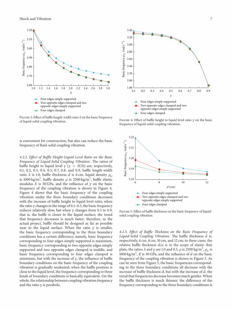
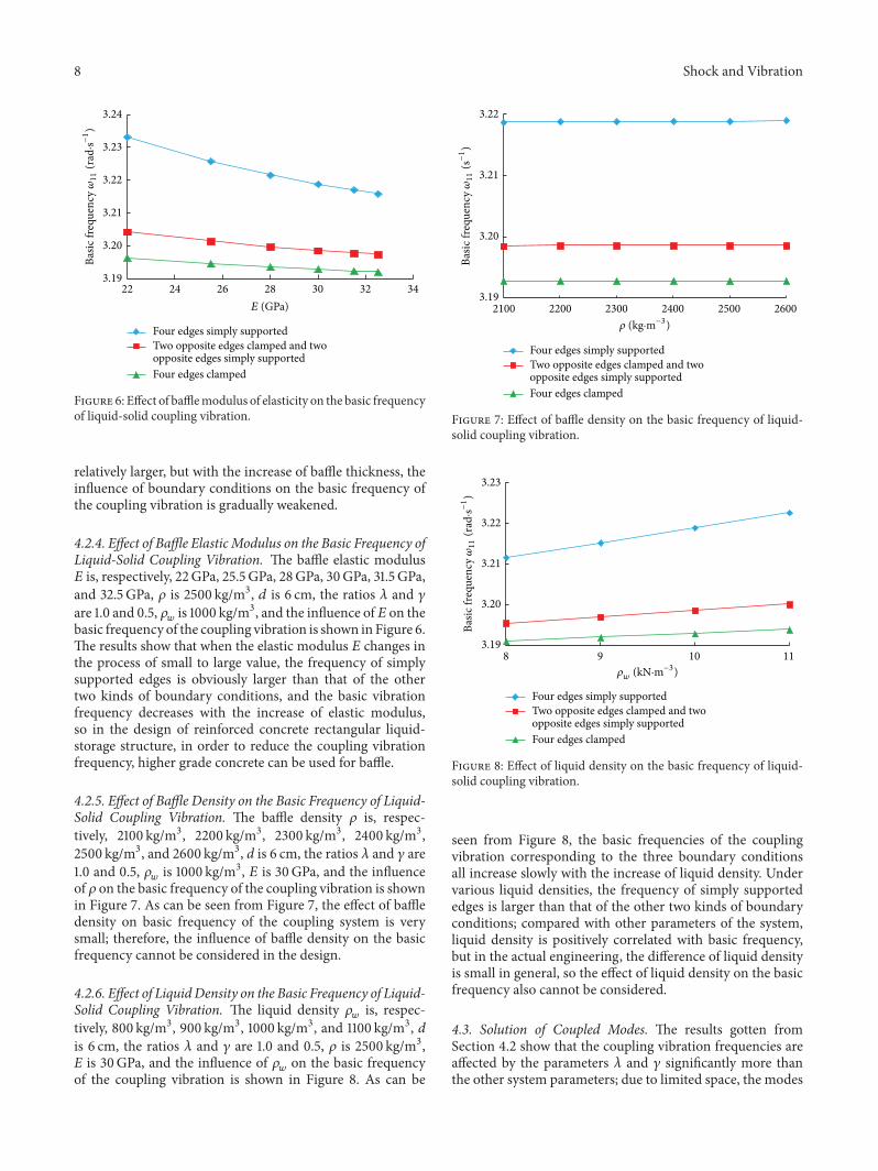

International Journal of
AerospaceEngineeringHindawi Publishing Corporationhttpwwwhindawicom Volume 2014
RoboticsJournal of
Hindawi Publishing Corporationhttpwwwhindawicom Volume 2014
Hindawi Publishing Corporationhttpwwwhindawicom Volume 2014
Active and Passive Electronic Components
Control Scienceand Engineering
Journal of
Hindawi Publishing Corporationhttpwwwhindawicom Volume 2014
International Journal of
RotatingMachinery
Hindawi Publishing Corporationhttpwwwhindawicom Volume 2014
Hindawi Publishing Corporation httpwwwhindawicom
Journal ofEngineeringVolume 2014
Submit your manuscripts athttpwwwhindawicom
VLSI Design
Hindawi Publishing Corporationhttpwwwhindawicom Volume 2014
Hindawi Publishing Corporationhttpwwwhindawicom Volume 2014
Shock and Vibration
Hindawi Publishing Corporationhttpwwwhindawicom Volume 2014
Civil EngineeringAdvances in
Acoustics and VibrationAdvances in
Hindawi Publishing Corporationhttpwwwhindawicom Volume 2014
Hindawi Publishing Corporationhttpwwwhindawicom Volume 2014
Electrical and Computer Engineering
Journal of
Advances inOptoElectronics
Hindawi Publishing Corporation httpwwwhindawicom
Volume 2014
The Scientific World JournalHindawi Publishing Corporation httpwwwhindawicom Volume 2014
SensorsJournal of
Hindawi Publishing Corporationhttpwwwhindawicom Volume 2014
Modelling amp Simulation in EngineeringHindawi Publishing Corporation httpwwwhindawicom Volume 2014
Hindawi Publishing Corporationhttpwwwhindawicom Volume 2014
Chemical EngineeringInternational Journal of Antennas and
Propagation
International Journal of
Hindawi Publishing Corporationhttpwwwhindawicom Volume 2014
Hindawi Publishing Corporationhttpwwwhindawicom Volume 2014
Navigation and Observation
International Journal of
Hindawi Publishing Corporationhttpwwwhindawicom Volume 2014
DistributedSensor Networks
International Journal of