research article position control of pneumatic actuator
TRANSCRIPT

Research ArticlePosition Control of Pneumatic ActuatorUsing Self-Regulation Nonlinear PID
Syed Najib Syed Salim1 Mohd Fuarsquoad Rahmat2 Ahmad rsquoAthif Mohd Faudzi23
Zool H Ismail23 and Noorhazirah Sunar2
1 Department of Control Instrumentation and Automation Faculty of Electrical Engineering Universiti Teknikal Malaysia MelakaHang Tuah Jaya 76100 Durian Tunggal Melaka Malaysia
2 Department of Control and Mechatronics Engineering Faculty of Electrical Engineering Universiti Teknologi Malaysia81310 Skudai Malaysia
3 Center for Artificial Intelligence and Robotics Universiti Teknologi Malaysia 54100 Kuala Lumpur Malaysia
Correspondence should be addressed to Mohd Fuarsquoad Rahmat fuaadfkeutmmy
Received 26 February 2014 Accepted 28 May 2014 Published 22 June 2014
Academic Editor Jun-Juh Yan
Copyright copy 2014 Syed Najib Syed Salim et al This is an open access article distributed under the Creative Commons AttributionLicense which permits unrestricted use distribution and reproduction in any medium provided the original work is properlycited
The enhancement of nonlinear PID (N-PID) controller for a pneumatic positioning system is proposed to improve the performanceof this controller This is executed by utilizing the characteristic of rate variation of the nonlinear gain that is readily available in N-PID controller The proposed equation namely self-regulation nonlinear function (SNF) is used to reprocess the error signal withthe purpose of generating the value of the rate variation continuously With the addition of this function a new self-regulationnonlinear PID (SN-PID) controller is proposed The proposed controller is then implemented to a variably loaded pneumaticactuator Simulation and experimental tests are conducted with different inputs namely step multistep and random waveformsto evaluate the performance of the proposed technique The results obtained have been proven as a novel initiative at examiningand identifying the characteristic based on a new proposal controller resulting from N-PID controller The transient response isimproved by a factor of 22 times greater than previous N-PID technique Moreover the performance of pneumatic positioningsystem is remarkably good under various loads
1 Introduction
Pneumatic actuators are widely used in various industrialapplications particularly for those involving manufacturingsystems such as pick and place motion robot manipulatorand rivet machine It is reliable fast acting with high acceler-ations of low cost flexible in installation simple to maintainof high power to weight ratio and free from overheating inthe case of constant load [1 2] It is an alternative to hydraulicactuators when cleanliness is one of the requirements How-ever this actuator exhibits highly nonlinear characteristic dueto high friction forces compressibility of air and dead bandof the spool movement in the valve These nonlinearitiesmake an accurate position control of a pneumatic actuatordifficult to achieve Research on these groups of actuatorshas increased in 1990s due to many control strategies that
had been tested to the system such as PID control PDplus sliding mode control robust control adaptive controland PWM control [3ndash6] Meanwhile more advanced controlstrategies are aggressively investigated and applied on theearly 2000s onward such as the research reported by [7ndash11] Consequently in the last 10 years the performance ofpneumatic positioning system is continuously improved
The dynamic model of the pneumatic actuator is charac-terized by significant nonlinearities Therefore it is difficultfor linear controllers such as PID to provide satisfactoryperformance for such a system especially when there is achange in load However it can be rectified by modifying itsstructure to increase the flexibility of the control parametersIn [12] an automatic tuning method to control the positionaccurately has been proposed The control algorithm used isan enhanced PID control that augmented with velocity and
Hindawi Publishing CorporationMathematical Problems in EngineeringVolume 2014 Article ID 957041 12 pageshttpdxdoiorg1011552014957041
2 Mathematical Problems in Engineering
acceleration feed forward bounded integral action and non-linear friction compensation Experimental results for stepresponse indicate that the steady state error was 02mm withovershoot Previously the modification of PID controllerhas been performed by adding the bounded integral actionposition feed forward and friction compensation as reportedin [13] The impact of this modification has improved theperformance of the controller The robustness has increasedsixfold in the system mass and was able to follow the S curvetrajectory smoothly without affecting the performance insteady state condition Moreover the results indicate that theuse of friction compensation was able to reduce the steadystate error by 40
In a subsequent study a practical control strategy basedon modification of PID controller by adding accelerationfeedback and nonlinear compensation has been proposed by[5] Position compensation algorithm with time delay mini-mization was realized to achieve the position target preciselyThe result with different levels of offset showed an improve-ment compared to conventional PID controller Besidesthe stability of the system has much improved by usingacceleration feedback The implementation of fractional-order controller for pneumatic position servosystemhas beeninvestigated by [14] In this research the FOPID controllersPI120582D120575 are implemented The aim of their study is to solvethe strong nonlinearity and low natural frequency problemIn the other research authors in [15] have proposed acombination of the conventional PID controller with fuzzylogic inference in which the parameters of the conventionalcontroller were tuned automatically to obtain the preciseposition control of pneumatic actuator Moreover a frictioncompensation and stabilization algorithm was added toensure that the accurate positioning be achieved The resultsindicate that the positioning accuracy was within the marginof 1mm The study on combination between PID and fuzzylogic is also reported in [16] In this study stability of thecontroller is theoretically proved according to the small gaintheorem Experimental results signify that the proposed fuzzyPID has better performance than classical PID
With the reason of PID control being vastly popularcontrol strategy in the industry a mixture of conventionalPID controller and the neural network which has powerfulcapability of learning adaptation and tackling nonlinearityhas been proposed by [10]The experiments have been carriedout in practical pneumatic artificial muscle for both caseswithout and with external inertia load up to 20 kg cm2Comparison with conventional PID controller has shownthat the proposed method presents better performance andhas the ability to compensate the disturbance In anotherresearch suggested by [11] an adaptive fuzzy PD controlleris used to compensate the friction The aim is to ensurethe movement of the stroke to the set point quickly andprecisely without significant overshoot The authors claimedthat the settling time and steady state error under constantload have obtained less than 1 s and 03mm respectivelywithout significant overshoot In the other research due tothe drawback of adaptive controllers that are not fast enoughto follow the parameter variation a multimodel controller
based on several fixed PD-controllers is recommended by[17]This techniquewas proposed for the position control of apneumatic cylinder under variable loads Five PD controllershad been tuned based on the estimated model for the fivefixed loads that has been identified earlier Experimentalresults show that this technique successfully improved theability in producing outstanding performances even undervariable load conditions
In previous work PID controller that incorporates withnonlinear gain namely N-PID controller was designed tocontrol the position and tracking of pneumatic actuator [18]The nonlinear gain is used to reduce overshoot when therelatively large gain is utilized Experimental results indicatethat the performance of the systemwithN-PID controller hassignificantly improved referring to its capability to performwith load up to 20 kg In this paper the enhancement ofthe nonlinear PID controller is proposed to improve theperformance especially in the transient part Recap thatthe N-PID controller has two parameters namely rangeof variation (119890max) and rate of variation (120572) [18ndash20] Thoseparameters need to be determined in advance It is intricate tochoose the appropriate combination of these parameters Toovercome this difficulty modifications have been made withthe purpose of generating these parameters automaticallywhich is dependent on the changes of error This indirectlycontributes to the time reduction in determining the param-eters and makes it more flexible with respect to the changesin position
This paper is organized as follows In Section 2 math-ematical modelling of the pneumatic actuator is describedIn Section 3 a self-regulation nonlinear PID (SN-PID) con-troller is described in detail In Section 4 the proposedmethod is simulated using MATLABSIMULINK Subse-quently experiments are carried out to verify the effectivenessof the proposed method in real time and analysis of perfor-mance under variation of load has been investigated FinallySection 5 contains some concluding remarks
2 System Model
The system consists of
(i) 53 bidirectional proportional control valve (EnfieldLS-V15s)
(ii) double acting with double rod cylinder
(iii) noncontact micropulse displacement transducer withfloating magnet (Balluff BTL6)
(iv) data acquisition card (NI-PCI-6221 card)
(v) pressure sensors (WIKA S-11)
(vi) personal computer and
(vii) Jun Air Compressor
The pneumatic cylinder with 500mm stroke for both sidesand 40mm in diameter is fixed on the base One side of thepiston rod is connected to the carriage and drives an inertialload on guiding rails The displacement transducer is fixed
Mathematical Problems in Engineering 3
Pneumatic cylinderPC
Pressure sensor
Carriage
ProportionalvalveDisplacement transducer
CompressorDAQ
Figure 1 Pneumatic positioning system experimental setup
D
C
A
B++++ yu
1
s
Figure 2 State-space model structure
in parallel with the rail where the carriage is mounted Thedata acquisition and control routines that were implementedunder real-time workshop in MATLAB are realized by PCequippedwith a PCMcard Two pressure sensors are installedon both sides of the cylinder that allows the measurement ofdifferential pressure between two chambers Figure 1 showsthe experimental setup used to validate the proposedmethod
21 Mathematical Modelling Since the design is basedon modification PID controller system identification isemployed to obtain the transfer function of the systemThe experiments were conducted starting with collectingthe input and output data based on open loop systemwith sampling time of 001 second The input signal withmultiamplitude and frequency sine wave is used where 2000numbers of data have been collected A state space modelas shown in Figure 2 is used as a model structure of thesystem Synthesis of the state space control is based upon thefollowing system of equations
119909 (119905 + 119879119904) = 119860119909 (119905) + 119861119906 (119905) + 119870119890 (119905)
119910 (119905) = 119862119909 (119905) + 119863119906 (119905) + 119890 (119905)
(1)
where 119860 isin 119877119899times119899 119861 isin 119877
119899times119898 119862 isin 1198771times119899 and 119863 isin 119877
1times119898
represent the matrices of the system while 119909(119905) isin 119877119899
119910(119905) isin 119877 119906(119905) isin 119877119898 and 119870 isin 119877
119899times119898 represent the state-vector measured output measured input signal and noiserespectively 119890(119905) is the vector that represents the differencebetween themeasured output and the predicted output of themodel
The estimation of the parameters is computed by iterativesearch for a model through prediction-error minimization(PEM) method that gives the minimal prediction error vari-ance when applied to the working dataThrough thismethod
the parameters of the model are calculated by minimizing acost function of the prediction errors giving
119881119873 (120579 119885119873) =
1
119873
119873
sum
119896=1
1198902(119896 120579) (2)
where 119873 denotes the number of data samples For linearsystems the error can be expressed as
119890 (119896) = 119867minus1(120579) [119910 (119896) minus 119866 (120579) 119906 (119896)] (3)
Therefore the parameter estimation can be obtained through(2) and (3) by minimizing 119881119873 as follows
120579119873 = argmin
120579
1
119873
119873
sum
119896=1
119867minus1(120579) [119910 (119896) minus 119866 (120579) 119906 (119896)]
2 (4)
The following equation is the discrete state-space equationobtained through this identification process
119860 =[
[
2846 minus1350 8544 times 10minus1
2 0 0
0 05 0
]
]
119861 =[
[
0125
0
0
]
]
119862 = [minus3494 times 10minus2
3765 times 10minus2
minus3967 times 10minus2]
119863 = [0]
(5)
The state space in continuous form is then obtained usingzero order hold (ZOH) conversion method with samplingtime 119879119904 = 001 s This conversion method generates thecontinuous time input signal by holding each sample valueconstant over one sample period The following equationrepresents continuous state space of the system that has beenconverted in phase variable form
119860 =[
[
0 1 0
0 0 1
minus3887 times 10minus1
minus85530 minus15740
]
]
119861 =[
[
0
0
1
]
]
119862 = [92490 6385 minus5071 times 10minus1]
119863 = [0]
(6)
A continuous transfer function then can be defined as
119866119901 (119904) =
minus05071199042+ 6385119904 + 92490
1199043+ 15740119904
2+ 85530119904 + 0389
(7)
22 Dead-Zone of the Valve Dead-zone is an inevitable phe-nomenon for the valve which represents a loss of informationwhen the signal falls into the dead-band area It refers to asituationwhere at a certain range of input values does not giveany outputDead-zone characteristics are often unknown andcan drastically reduce control system performance and lead
4 Mathematical Problems in Engineering
Uz(u)
hz(u)
gz(u)
up
unu
Figure 3 Dead-zone characteristic
Nonlinear function
PID Pneumatic system
DZC
PSO
Input Output
120572i
+++minus k(e)
du
dt||
|| |
|120575
120573s + 1
Figure 4 Block diagram of self-regulation nonlinear PID (SN-PID)controller
to limit cycles in the closed loop system Figure 3 shows thegraphical representation of dead-zone characteristic 119880119911(119906)
A mathematical model for the dead-zone is given by
119880119911 (119906) =
119892119911 (119906) lt 0 119906 le 119906119899
0 119906119899 lt 119906 lt 119906119901
ℎ119911 (119906) gt 0 119906 ge 119906119901
(8)
where 119906119899 is negative limit of dead-zone 119906119901 is positive limit ofdead-zone 119892119911(119906) is negative slope of output ℎ119911(119906) is positiveslope of output 119880119911 is output and 119906 is input
3 Control Design
The conventional PID controller emphasizes a straight for-ward design approach to achieve the favourable result incontrolling the position and continuing motion as the ulti-mate goal However as position control performance is morerigorous this type of controller is often difficult to give thebetter performance due to the presence of nonlinearitiesespecially in pneumatic systems In previous work [18] thePID controller that is incorporated with automatic nonlineargain namely nonlinear PID controller was designed tocontrol the position and tracking of pneumatic actuator Theperformance of N-PID controller is better than conventionalPID controller in terms of robustness However there isstill room for improvement especially in the transient part
whereby the improvement by imposing a higher force in theinitial movement should be implemented to overcome thestatic friction
The aim of this paper is to design a controller sothat the displacement of this actuator can reach the targetquickly and accurately without significant overshoot For thisgoal an additional function was added to the controller incompensating the nonlinearities of the system This functionwill continuously generate the value of rate variation (120572) toregulate the output of the nonlinear function The proposedtechnique is called self-regulation nonlinear PID (SN-PID)controller This technique is suitable to be used in theindustry due to its ability to execute in such a short periodof time and effectiveness to reach the performance that isunable to achieve by both conventional PID controller andnonlinear PID controller The proposed method was indeedmore efficient and robust in improving the step response ofpneumatic positioning system
31 Design of Self-Regulation Nonlinear PID (SN-PID) Con-troller The proposed controller is an enhancement from theN-PID controller Asmentioned in the previous work [18] theN-PID controller is bounded by a sector of nonlinear gain119896119909(119890) The value of nonlinear gain is continuously changeddepending on the changes of error The appropriate value ofboth rate variation 120572 and the boundary of maximum error119890max is selected by the userThe value of 119890max is set by any valuedepending on sector where the nonlinear function will takeaction In previous work the parameter of rate variation 120572 isdetermined based on trial and error after taking into accountthe stability region of the system However the selected valueof 120572 is limited to certain circumstances Besides the optimalvalue of 120572 is difficult to determine in producing outstandingperformance in terms of speed and chattering avoidance Inthis study the value of 120572 is generated on-line to provideflexibility to the controller Figure 4 shows the block diagramof the proposed method The value of nonlinear gain 119896119909(119890)is automatically varied depending on the value of 120572119894 that ison-line generated using proposed equation as defined in
120572119894 (119904)
119890 (119904)
=
119889
119889119904
10038161003816100381610038161003816100381610038161003816
120575
120573119904 + 1
10038161003816100381610038161003816100381610038161003816
(9)
This equation is called self-regulation nonlinear func-tion (SNF) It has a simple structure and does not requiremore computation time For the purpose to generate 120572automatically the relationship between 120575 and 120573 needs to bedetermined in advance The details on how to determinethese parameters are described in the next subsection Thenonlinear gain is defined under the limitation of 0 lt 119896119909(119890) le119896(119890max) giving
119896119909 (119890) =
exp (120572119894119890) + exp (minus120572119894119890)2
119890 =
119890 |119890| le 119890max
119890max sign (119890) |119890| gt 119890max
(10)
Mathematical Problems in Engineering 5
where
119896 (119890max) = minus1
1003816100381610038161003816119866 (119895120596)
1003816100381610038161003816
(11)
Theoutput produced from thenonlinear function is known asa scaled error which is expressed in (12) The whole equationof the proposed SN-PID controller is written as (13)
119891119909 (119890) = 119896119909 (119890) sdot 119890 (119905) (12)
119906PID sdot119891119909 (119890)= 119896119901(sdot) 119890 (119905) + 119896119894 (sdot)int119905
0
[119890 (119905)] 119889119905 + 119896119889 (sdot)
119889
119889119905
[119890 (119905)]
(13)
where (sdot) corresponds to the controller gains that are timevarying which depend on input and other variables
32 Determination of 120575 and 120573 In order to identify therelationship between 120575 and 120573 a particle swarm optimization(PSO) technique is employed It is a stochastic optimiza-tion technique influenced by simulating the animal socialbehavior for example flocking of birds [21] This techniqueis initialized with a group of random solutions (particles)and searches for optima by updating generations Figure 5shows the flowchart for PSO algorithm used in this studyBased on this flowchart each particle randomly reached inthe early stages is a candidate solution and has a specificfitness valueThese particles will move with a certain velocitywhich is affected by its own flying experience and otherparticles flying experience Through the process velocityand position are updated with two best values namelypersonal best (119875best) solution and global best (119866best) solu-tion For example the 119894th particle is expressed as 119909119894 =
(1199091198941 1199091198942 119909119894119889) in d-dimensional space Previous bestposition (119875best) of the 119894th particle is stored and expressedas 119875best119894 = (119875best1198941 119875best1198942 119875best119894119889) The best particleindex among all the particles in a flock or group is specified as119866best Thus the velocity and position of each particle can becalculated using the current velocity and distance from 119875bestto 119866best as described in (14) and (15) respectively
119881119905+1
119894= 119908 sdot 119881
119905
119894+ 1198881 sdot rand1 (sdot) sdot (119875best119894 minus 119883
119905
119894)
+ 1198882 sdot rand2 (sdot) sdot (119866best119894 minus 119883119905
119894)
(14)
119883119905+1
119894= 119883119905
119894+ 119881119905+1
119894 (15)
The value of 119908 is set by (16) as follows
119908 = 119908max minus119908max minus 119908min
itrmaxtimes itr (16)
where 119908 is inertia weight function 1198881 and 1198882 are learningfactors rand1 and rand2 are random numbers in range [0 1]itrmax is maximum number of iterations and itr is currentiteration 119894 = 1 2 3 4 119873swarm
The performance criterion in the time domain asdescribed in (17) is employed for this optimization It isused in calculating the cost function for evaluating the
Randomly initialize agent position and velocity
Calculate particle fitness
Start
End
Update velocity for each particle
Update position for each particle
Target or max epochs reached
For e
ach
itera
tion
For e
ach
part
icle
Yes No
Keep previousPbest record
Update Pbestrecord
Updat Gbest record
Current fitnessbetter than Pbest
Specify the lower and upper bounds of 120572
Parameters setting (Nw c1 c2 120575 and 120573)
Figure 5 Flow chart for particle swarm optimization technique
parameters of self-regulation nonlinear function (SNF) Theoutput response constraint including overshoot rise timesettling time and steady state error is taken into account inthis performance criterionThe cost function119891 is a reciprocalof the performance criteria119882(119870) as defined in
119882(119870) = (119872119875 + 119890ss) sdot (1 minus 119890minus120590) + (119905119878 minus 119905119903) sdot 119890
minus120590 (17)
119891 =
1
119882 (119870)
(18)
where 119870 is [120575 120573] and 120590 is the weighting factor Accordingto [22] the value of 120590 should be larger than 07 to reducesteady state error and overshoot In this study this value isset equal to 09 Referring to (9) as far as stability of thesystem is concerned the value of 120575 should be selected less
6 Mathematical Problems in Engineering
120
130
140
150
160
170
240 260 280 300 320 340
Valu
e of120575
Value of 120573
Figure 6 Relationship between 120575 and 120573
than 120573Otherwise the value of rate variation 120572will extremelyincrease and it causes the system to become unstable Asmentioned earlier the value of 120575 and 120573 can be determined byidentifying the relationship between them For this purposethe PSO algorithm was run several times and the results ofthese parameters are tabulated in Table 1 Figure 6 shows therelationship between 120575 and 120573 based on these optimizationprocesses From this graph it can be concluded that 120575 and120573 are directly proportional to each other with a slope of 051Through this observation the equation as expressed in (19)was applied to determine the value of 120575 and 120573
120575 = 051120573 (19)
Figure 7(a) shows the response produced from SNF forthe system tested with step input 200mm By differentiatingthis response the rate variation 120572 is obtained as presentedin Figure 7(b) Based on this response the rate variation isdecreasing starting at 013 and ending at 0 where the steadystate response is achieved It indicates that the value of 120572is high for the beginning of each movement and graduallydeclines when the piston starts moving This will drivethe system output to its goal rapidly without significantovershoots and be able to prevent excessive oscillationsMoreover the varying of 120572will generate the numerous rangesof nonlinear gain 119896119909(119890) and increase the flexibility of thecontroller
33 System Stability In any controller design it is necessaryto ensure the stability of the system Since the value of ratevariation 120572 is generated automatically the selected value ofboth weighting factors 120575 and 120573 should take into accountthe maximum value of the nonlinear gain 119896119909(119890) The Popovstability criterion is used in determining the maximum valueof 119896119909(119890) The absolute stability of the equilibrium states ofnonlinear systems by applying Popov criterion is based onthe modified amplitude-phase characteristic of the linearpart of the system The procedure to determine the rangeof 119896119909(119890) using Popov stability criterion has been discussedin detail in [20] By using Matlab software the Popov plotof 119866(119895120596) is crossing the real axis at the point (minus014 1198950) as
Table 1 Parameter determination via particle swarm optimization
Op1 Op2 Op3 Op4 Op5119882 0048 0030 0039 0052 0041120575 1679 1412 1589 1445 12951120573 3244 2675 3052 2853 24853120575 120573 0518 0528 0521 0506 0521
shown in Figure 8 Based on this information the maximumvalue of the nonlinear gain 119896(119890max) can be obtained through(19)Therefore according to the Popov stability criterion therange of the allowable nonlinear gain 119896119909(119890) is (0 714)
34 Effectiveness of the ProposedMethod in Industrial Applica-tion Theprerequisite in designing a controller is practicalityTherefore its ability to be implemented on the real plant isone of the criteria that need to be taken into account Theresulting output of the controller during transient periodshould be within the limitation of the system hardwareWithout taking this into account the presence of integratorwindup phenomenon surely will degrade the performanceof the system This phenomenon occurs when the controlleroutput saturates due to integral terms and this generallyleads to large settling times and overshoots In this studythe saturation limit of the hardware is within plusmn10 voltThrough the proposed method the controller variables areonly allowed to be at saturation point for a short periodof time This can be seen as shown in Figure 9(a) whenthe multistep command inputs are applied to the systemWhere the amplitude of the controller output is only atsaturation point in a short period of time which is about5ms even the distance of the movement is increased Theother controllers namely SMC and PID have been appliedto the system for comparison purposes Figure 9(b) illustratesthe controller output of this controller when operating underdistance of 460mm For the purposes of comparison theoutput controller for PID and SMC is depicted in Figure 10
35 Design of Dead-Zone Compensator Due to the existenceof dead-zone for the spool movement in opening and closingof the valve the presence of delay is unavoidable The dead-zone compensator used in this study is based on the researchconducted by [23] It was implemented by using the followingconditions
(1) If absolute error is small or equal to the desired valueof error the output of DZC is represented by 1198801198900
(2) if absolute error is greater than the desired value oferror and the controller output is greater than zerothe output of DZC is represented by 119906119901
(3) if absolute error is greater than the desired value oferror and the controller output is less than zero theoutput of DZC is represented by 119906119899
where 1199061198900 119906119901 and 119906119899 are input compensation based on errorpositive dead-zone compensation and negative dead-zonecompensation respectively Based on these conditions thereis no force imposed to the payload when the output of the
Mathematical Problems in Engineering 7
Am
plitu
de o
f reg
ulat
ion
0
001
002
003
004
10 2 3Time (s)
(a)
10 2 30
005
01
015
02
Time (s)Ra
te v
aria
tion120572
(b)
Figure 7 Response of the regulation block diagram (a) output before differentiating (b) rate variation
Popov plotPopov line
times104
0
minus1
minus2
minus3
0
minus1
minus2
minus3
minus4
minus1500 minus1000 minus500 0
minus03 minus02 minus01
Figure 8 Graphical solution using Popov analysis
DZC is represented by 1199061198900 For the other conditions in whichthe position error exceeded 119890119889 in either positive or negativedirection the output of the controller will be added to thedead zone compensators 119906119901 and 119906119899 respectively
4 Results and Discussion
Simulation and experimental validation are performed toevaluate the performance of the proposed SN-PID withdifferent step of inputs and various masses of the loadThe controller was designed for the system with a nom-inal payload mass of 32 kg The difference between thenominal and other masses of payload was tested to illus-trate the robustness of the proposed controller The per-formance of the proposed technique is compared to theother techniques namely conventional PID N-PID andSMC controller The parameters of the proposed controllerincluding self-regulation nonlinear function (SNF) and otherparameters are tabulated in Table 2 The parameters ofthe PID should be determined earliest before the otherparameters can be obtained The procedures to obtain PIDcontroller parameters have been given in the previous work[18]
41 Simulation Results In this section the performances ofthe proposed method are presented via simulation beforebeing realized in real time The system which has beensimulated with the input consists of a variety of distancesTheresult indicates that the system has successfully maintainedthe performance of the system It can be seen in Figure 11(a)where the transient response is quite similar for each tran-sition of the step input The changes occur in the value of120572 for each transition as shown in Figure 11(b)which givesinformation to the nonlinear function in determining the
8 Mathematical Problems in Engineering
Table 2 Parameters of the controller
Control strategies Control parametersName of parameter Abbreviation Value
PID
Proportional gain 119870119901 2099Integral gain 119870119894 956 times 10minus3
Derivative gain 119870119889 0035Filter 119873 12207
SN-functionParam 1 120575 12951Param 2 120573 24853Variation of error 119890max 2
Dead-zone compensator
Control value in the range of desired 119890ss 1199061198900 001+ve dead-zone compensation 119906119901 05minusve dead-zone compensation 119906
119899minus065
Desired 119890ss 119890119889 0005
Disp
lace
men
t (m
m)
200
10050
150
0
Time (s)0 5 10 15 20 25 30 35 40
minus100
minus150
minus50
minus200
(a)
Con
trolle
r ou
tput
(V)
Con
trolle
r ou
tput
(V)
300230 3004 3006 3008 301
300230 3004 3006 3008 31
9697989910
Time (s)
Time (s)0 5 10 15 20 25 30 35 40
1050
1086420
minus5minus10
(b)
Figure 9 Response for the system with SN-PID (a) displacement(mm) (b) controller output
appropriate value of nonlinear gain 119896119909(e)The correspondingresponse of the controller output is shown in Figure 11(c)
It clearly can be seen that the amplitude of the responseis within the limits allowed by the data acquisition card thatis used in the experiment which is between minus10 v and +10 vSuch a situation is relieving to ensure that the output response
Time (s)30 31302298 304 306 308
10
0
2
4
6
8C
ontro
ller o
utpu
t(V
)
(a)
Time (s)
1011
0
21
3456789
Con
trolle
r out
put(
V)
30 31 312 314302298 304 306 308
(b)
Figure 10 Controller output of the system with (a) PID and (b)SMC
may be generated without the overshoot for both simulationand experimental validation In addition the signal withrandom input is also employed to strengthen the evidencethat the SN-PID controller can cater various forms of inputThis can be observed as indicated in Figure 12(a) The resulthas confirmed that the proposed controller is able to track thedemand even in the case where the input response is changedall of a sudden Figure 12(b) shows the reaction of the rate
Mathematical Problems in Engineering 9
Time (s)
Disp
lace
men
t (m
m)
0 5 1510 20 25 30 35 40
150
100
50
0
minus50
minus100
(a)
Time (s)0 5 10 15 20 25 30 35 40
12
14
08
1
06
04
02
0
Rate
var
iatio
n (120572)
(b)
Time (s)
Con
trolle
r out
put (
V)
6420
minus6
minus4
minus2
minus8
minus12
minus10
0 5 10 15 20 25 30 35 40
(c)
Figure 11 Performance of system controller by SN-PID controller (a) displacement (mm) (b) rate variation 120572 and (c) controller output (v)
variation (120572) which acts as an essential variable in order toensure that various forms of input can be handled well
42 Experimental Validation In order to verify the perfor-mance of the proposed controller the result from simulationis compared to the result obtained from the real-time systemAs can be seen from Figure 13 the response obtained basedon experimental validation is quite similar to the simulationThere is only a slight difference on the transient part inwhich the response from experimental result is a bit fastercompared to the simulation Subsequently to strengthen theevidence of the effectiveness of the designed controller theexperiment with various types of input is conducted Theseresults have confirmed that the acceptable performance isachieved for both experimental validation and simulationwhere the real-time response of the pneumatic system alsolooks quite similar to the simulation
43 Performance Analysis on the Variation of Load One ofthe issues that need to be taken into account in designinga controller is the ability of the controller to compensatethe system when there are changes occurring in the loadIn this section the results from several experiments with
different load are combined and investigated This system istested using step response with displacement of 400mmThemoving mass of the horizontal cylinder is attached to theload of 32 kg 84 kg 135 kg 23 kg and 28 kg Based on theresult as shown in Figure 14 the proposed controller is ableto accommodate to the system for various changes of loadApparently it can be seen that the proposed technique is ableto control the system evenwhen the load is added up to 28 kgThe steady state error under these variations of the load isquite similar which is around 001mm
44 Performance Comparison with the Other Methods Asa benchmark the proposed controller has been comparedto the other methods The comparison of the performancebetween the proposed SN-PID N-PID conventional PIDand slidingmode control (SMC) is performed using the sametest rig For sliding mode control the sliding surface for thirdorder is defined as follows
119878 = 119910 minus 119910119889 + 2120582 (119910 minus 119910119889) + 120582
2(119910 minus 119910119889)
(20)
By taking derivative of (20) and setting 119878 = 0 the equivalentcontrol signal 119906eq therefore can be obtained by substitutingthe plant model The switching control signal as in (21) is
10 Mathematical Problems in EngineeringD
ispla
cem
ent (
mm
)
InputOutput
150
100
50
0
Time (s)0 5 10 15 25 3520 30 40
minus100
minus50
(a)
06
05
04
03
02
01
0
Rate
var
iatio
n (120572)
Time (s)0 5 10 15 20 25 30 35 40
(b)
Figure 12 Performance of system controller by SN-PID withvarious forms of input (a) output and (b) rate variation 120572
employed The controller parameters are set to the values120593 = 1087 and 120582 = 36
119906119904 = minus119896119904 sat(119878
120593
) (21)
where
sat( 119878120593
) =
119878
120593
10038161003816100381610038161003816100381610038161003816
119878
120593
10038161003816100381610038161003816100381610038161003816
le 1
sign( 119878120593
)
10038161003816100381610038161003816100381610038161003816
119878
120593
10038161003816100381610038161003816100381610038161003816
gt 1
(22)
The results indicate that the proposed controller namelySN-PID controller has performed better compared to theother methods It can be seen in Figure 15 that the output ofthe system controlled by SN-PID shows a better performancein transient part compared to others In the same experimentthe result for the system controlled by N-PID controller isworst in terms of speed compared to others However bytaking into consideration the robustness of the system SN-PID and N-PID controller give better performance undervarious loads compared to the others This is due to thenumbers of oscillation appearing in the output responsefor the system controlled by conventional PID and SMC as
Simulation
Experimental
Simulation
Experimental
SimulationExperimental
Disp
lace
men
t (m
m)
200100
0minus100
Disp
lace
men
t (m
m)
100
0
minus100
Time (s)0
98
5 10 15 20 25 30 35 40
Time (s)0 5 10 15 20 25 30 35 40
140
40
2030
100
120
150
130
110
9014 145 155
255 265 275
75 85
285
15
Figure 13 Experimental validations for the system with SN-PIDcontroller
depicted in zoom-in view Moreover based on the resultsas illustrated in Figure 14 it has been proved that the SN-PID controller is able to operate under variations of load upto 28 kg The steady state error for the system controlled bySN-PID and N-PID is about 001mm while for the systemcontrolled by other controllers it is about 01mm to 05mm
5 Conclusion
In this research a new technique namely self-regulationnonlinear PID (SN-PID) controller is proposed and designedto control the position of pneumatic actuator system Thepurpose of this technique is to enhance the performanceof nonlinear PID (N-PID) controller that was tested tothe system previously This was performed by utilizing thecharacteristic of rate variation of nonlinear gain via equationwhich is known as regulation function The purpose of thistechnique is to make the controller be flexible with severalsector-bounded of gain Simulations and experiments wereconducted to verify the performance of the proposed tech-nique and found that the transient response is improved by afactor of 22 times better than previousN-PID technique withbetter steady state response In addition the experimentalresults also confirmed that the SN-PID controller is capableof keeping up the performance under the variation of load upto 28 kgThe performances as shown in the results prove thatthe objective of the proposed controller has been successfullyachieved referring to the reduction of the time taken from thestroke to reach the steady state condition
Conflict of Interests
The authors declare that there is no conflict of interestsregarding the publication of this paper
Mathematical Problems in Engineering 11
Disp
lace
men
t (m
m) Nominal loadInput
Time (s)
84 kg 135kg
23kg 28kg
200100
0 1 3 5 7 92 4 6 8 10Time (s)
0 1 3 5 7 92 4 6 8 10
Time (s)0 1 3 5 7 92 4 6 8 10
Time (s)0 1 3 5 7 92 4 6 8 10
Time (s)0 1 3 5 7 92 4 6 8 10
Time (s)0 2 4 6 8 10
minus100
minus200
0
Disp
lace
men
t (m
m)
200100
minus100
minus200
0
Disp
lace
men
t (m
m)
200100
minus100minus200
0D
ispla
cem
ent (
mm
)
200100
minus100
minus200
0
Disp
lace
men
t (m
m)
200100
minus100
minus200
0
Disp
lace
men
t (m
m)
200100
minus100
minus200
0
Figure 14 Experimental results under various loads
10 3 5 7 92 4 6 8 10
0
10050
150
250200
Disp
lace
men
t (m
m)
Time (s)
Input SNPIDNPIDsmc
PID
minus100
minus50
minus150
minus200
minus250
210
200
190
180
170
18 2 22 24 26 28
Figure 15 System responses with load 135 kg for different con-troller
Acknowledgments
This research is supported by Ministry of Higher Edu-cation (MOHE) Malaysia Universiti Teknologi Malaysia(UTM) and Universiti Teknikal Malaysia Melaka (UTeM)through Research University Grant (GUP) Tier 1 vote noQJ130000712300H36 Authors are grateful to MinistryUTM and UTeM for supporting the present work
References
[1] A C Valdiero C S Ritter C F Rios and M Rafikov ldquoNon-linear mathematical modeling in pneumatic servo positionapplicationsrdquo Mathematical Problems in Engineering vol 2011Article ID 472903 16 pages 2011
[2] A A M Faudzi N D M Mustafa and K Osman ldquoForcecontrol for a pneumatic cylinder using generalized predictivecontroller approachrdquo Mathematical Problems in Engineeringvol 2014 Article ID 261829 5 pages 2014
[3] T Shen K TamuraNHenmi andTNakazawa ldquoRobustmodelfollowing controller applied to positioning of pneumatic controlvalve with frictionrdquo in Proceedings of the IEEE InternationalConference on Control Applocations vol 1 pp 512ndash516 TriesteItaly September 1998
[4] L Reznik O Ghanayem and A Bourmistrov ldquoPID plus fuzzycontroller structures as a design base for industrial applica-tionsrdquo Engineering Applications of Artificial Intelligence vol 13no 4 pp 419ndash430 2000
[5] J Wang J Pu and P Moore ldquoA practical control strategyfor servo-pneumatic actuator systemsrdquo Control EngineeringPractice vol 7 no 12 pp 1483ndash1488 1999
[6] E Richer and Y Hurmuzlu ldquoA high performance pneumaticforce actuator system Part 2mdashnonlinear controller designrdquoASME Journal of Dynamic Systems Measurement and Controlvol 122 no 3 pp 426ndash434 2000
[7] S R Pandian F Takemura Y Hayakawa and S KawamuraldquoPressure observer-controller design for pneumatic cylinderactuatorsrdquo IEEEASME Transactions onMechatronics vol 7 no4 pp 490ndash499 2002
12 Mathematical Problems in Engineering
[8] F Xiang and J Wikander ldquoQFT control design for an approxi-mately linearized pneumatic positioning systemrdquo InternationalJournal of Robust and Nonlinear Control vol 13 no 7 pp 675ndash688 2003
[9] H Schulte and H Hahn ldquoFuzzy state feedback gain schedulingcontrol of servo-pneumatic actuatorsrdquo Control EngineeringPractice vol 12 no 5 pp 639ndash650 2004
[10] K Ahn and T Thanh ldquoNonlinear PID control to improve thecontrol performance of the pneumatic artificial muscle manip-ulator using neural networkrdquo Journal of Mechanical Science andTechnology vol 19 no 1 pp 106ndash115 2005
[11] X Gao and Z-J Feng ldquoDesign study of an adaptive Fuzzy-PD controller for pneumatic servo systemrdquo Control EngineeringPractice vol 13 no 1 pp 55ndash65 2005
[12] S Aziz and G M Bone ldquoAutomatic tuning of an accurateposition controller for pneumatic actuatorsrdquo in Proceedings ofthe IEEERSJ International Conference on Intelligent Robots andSystems vol 3 pp 1782ndash1788 Victoria Canada October 1998
[13] R B van Varseveld and G M Bone ldquoAccurate positioncontrol of a pneumatic actuator using onoff solenoid valvesrdquoIEEEASME Transactions onMechatronics vol 2 no 3 pp 195ndash204 1997
[14] C Junyi and C Binggang ldquoFractional-order control of pneu-matic position servosystemsrdquo Mathematical Problems in Engi-neering vol 2011 Article ID 287565 14 pages 2011
[15] Z Situm D Pavkovic and B Novakovic ldquoServo pneumaticposition control using fuzzy PID gain schedulingrdquo ASMEJournalOfDynamic SystemsMeasurement andControl vol 126no 2 pp 376ndash387 2004
[16] S Cai SWu andG Bao ldquoCylinder position servo control basedon fuzzy PIDrdquo Journal of AppliedMathematics vol 2013 ArticleID 375483 10 pages 2013
[17] M Taghizadeh F Najafi and A Ghaffari ldquoMultimodel PD-control of a pneumatic actuator under variable loadsrdquo Interna-tional Journal of Advanced Manufacturing Technology vol 48no 5 pp 655ndash662 2010
[18] M F Rahmat S N S Salim N H Sunar A A M Faudzi ZH Ismail and K Huda ldquoIdentification and non-linear controlstrategy for industrial pneumatic actuatorrdquo International Jour-nal of the Physical Sciences vol 7 no 17 pp 2565ndash2579 2012
[19] H Seraji ldquoA new class of nonlinear PID controllers with roboticapplicationsrdquo Journal of Robotic Systems vol 15 no 3 pp 161ndash181 1998
[20] Y X Su D Sun and B Y Duan ldquoDesign of an enhancednonlinear PID controllerrdquoMechatronics vol 15 no 8 pp 1005ndash1024 2005
[21] J Kennedy and R Eberhart ldquoParticle swarm optimizationrdquoin Proceedings of the IEEE International Conference on NeuralNetworks vol 4 pp 1942ndash1948 Perth Australia December1995
[22] Z-L Gaing ldquoA particle swarm optimization approach foroptimum design of PID controller in AVR systemrdquo IEEETransactions on Energy Conversion vol 19 no 2 pp 384ndash3912004
[23] N Shu and G M Bone ldquoExperimental comparison of twopneumatic servo position control algorithmsrdquo in Proceedingsof the IEEE International Conference on Mechatronics andAutomation (ICMA rsquo05) vol 31 pp 37ndash42 August 2005
Submit your manuscripts athttpwwwhindawicom
Hindawi Publishing Corporationhttpwwwhindawicom Volume 2014
MathematicsJournal of
Hindawi Publishing Corporationhttpwwwhindawicom Volume 2014
Mathematical Problems in Engineering
Hindawi Publishing Corporationhttpwwwhindawicom
Differential EquationsInternational Journal of
Volume 2014
Applied MathematicsJournal of
Hindawi Publishing Corporationhttpwwwhindawicom Volume 2014
Probability and StatisticsHindawi Publishing Corporationhttpwwwhindawicom Volume 2014
Journal of
Hindawi Publishing Corporationhttpwwwhindawicom Volume 2014
Mathematical PhysicsAdvances in
Complex AnalysisJournal of
Hindawi Publishing Corporationhttpwwwhindawicom Volume 2014
OptimizationJournal of
Hindawi Publishing Corporationhttpwwwhindawicom Volume 2014
CombinatoricsHindawi Publishing Corporationhttpwwwhindawicom Volume 2014
International Journal of
Hindawi Publishing Corporationhttpwwwhindawicom Volume 2014
Operations ResearchAdvances in
Journal of
Hindawi Publishing Corporationhttpwwwhindawicom Volume 2014
Function Spaces
Abstract and Applied AnalysisHindawi Publishing Corporationhttpwwwhindawicom Volume 2014
International Journal of Mathematics and Mathematical Sciences
Hindawi Publishing Corporationhttpwwwhindawicom Volume 2014
The Scientific World JournalHindawi Publishing Corporation httpwwwhindawicom Volume 2014
Hindawi Publishing Corporationhttpwwwhindawicom Volume 2014
Algebra
Discrete Dynamics in Nature and Society
Hindawi Publishing Corporationhttpwwwhindawicom Volume 2014
Hindawi Publishing Corporationhttpwwwhindawicom Volume 2014
Decision SciencesAdvances in
Discrete MathematicsJournal of
Hindawi Publishing Corporationhttpwwwhindawicom
Volume 2014 Hindawi Publishing Corporationhttpwwwhindawicom Volume 2014
Stochastic AnalysisInternational Journal of
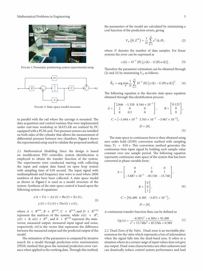
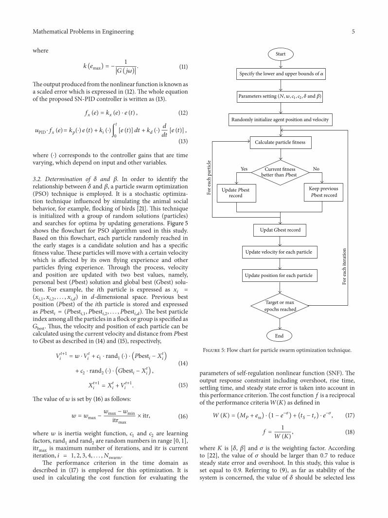
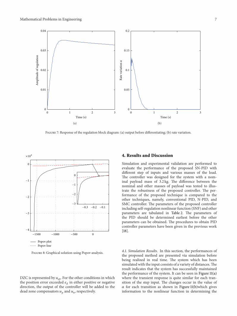
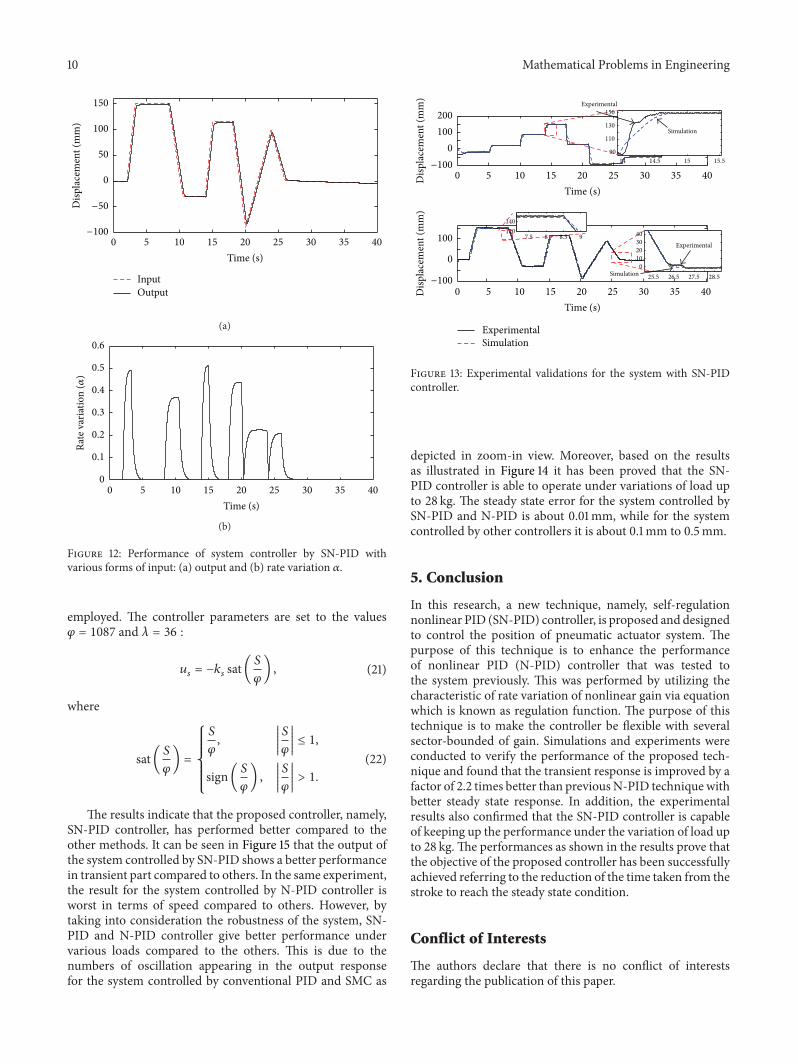