research article eso-based fuzzy sliding-mode control for...
TRANSCRIPT
Research ArticleESO-Based Fuzzy Sliding-Mode Control fora 3-DOF Serial-Parallel Hybrid Humanoid Arm
Yueling Wang, Runjie Shi, and Hongbin Wang
Institute of Electrical Engineering, Yanshan University, Qinhuangdao 066004, China
Correspondence should be addressed to Yueling Wang; [email protected]
Received 15 March 2014; Accepted 27 May 2014; Published 3 August 2014
Academic Editor: Onur Toker
Copyright © 2014 Yueling Wang et al. This is an open access article distributed under the Creative Commons Attribution License,which permits unrestricted use, distribution, and reproduction in any medium, provided the original work is properly cited.
This paper presents a unique ESO-based fuzzy sliding-mode controller (FSMC-ESO) for a 3-DOF serial-parallel hybrid humanoidarm (HHA) for the trajectory tracking control problem. The dynamic model of the HHA is obtained by Lagrange method andis nonlinear in dynamics with inertia uncertainty and external disturbance. The FSMC-ESO is based on the combination of thesliding-mode control (SMC), extended state observer (ESO) theory, and fuzzy control (FC).The SMC is insensitive to both internalparameter uncertainties and external disturbances. The motivation for using ESO is to estimate the disturbance in real-time. Thefuzzy parameter self-tuning strategy is proposed to adjust the switching gain on line according to the running state of the system.The stability of the system is guaranteed in the sense of the Lyapunov stability theorem. The effectiveness and robustness of thedesigned FSMC-ESO are illustrated by simulations.
1. Introduction
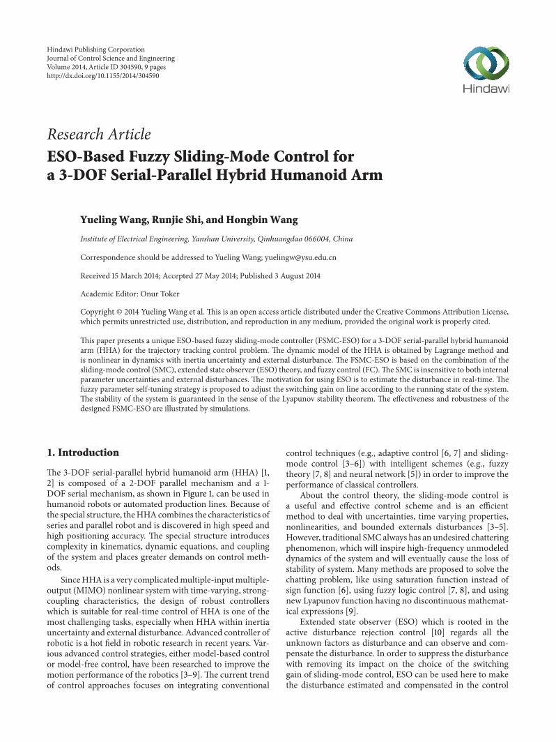
The 3-DOF serial-parallel hybrid humanoid arm (HHA) [1,2] is composed of a 2-DOF parallel mechanism and a 1-DOF serial mechanism, as shown in Figure 1, can be used inhumanoid robots or automated production lines. Because ofthe special structure, theHHAcombines the characteristics ofseries and parallel robot and is discovered in high speed andhigh positioning accuracy. The special structure introducescomplexity in kinematics, dynamic equations, and couplingof the system and places greater demands on control meth-ods.
SinceHHA is a very complicatedmultiple-inputmultiple-output (MIMO) nonlinear systemwith time-varying, strong-coupling characteristics, the design of robust controllerswhich is suitable for real-time control of HHA is one of themost challenging tasks, especially when HHA within inertiauncertainty and external disturbance. Advanced controller ofrobotic is a hot field in robotic research in recent years. Var-ious advanced control strategies, either model-based controlor model-free control, have been researched to improve themotion performance of the robotics [3–9]. The current trendof control approaches focuses on integrating conventional
control techniques (e.g., adaptive control [6, 7] and sliding-mode control [3–6]) with intelligent schemes (e.g., fuzzytheory [7, 8] and neural network [5]) in order to improve theperformance of classical controllers.
About the control theory, the sliding-mode control isa useful and effective control scheme and is an efficientmethod to deal with uncertainties, time varying properties,nonlinearities, and bounded externals disturbances [3–5].However, traditional SMC always has an undesired chatteringphenomenon, which will inspire high-frequency unmodeleddynamics of the system and will eventually cause the loss ofstability of system. Many methods are proposed to solve thechatting problem, like using saturation function instead ofsign function [6], using fuzzy logic control [7, 8], and usingnew Lyapunov function having no discontinuous mathemat-ical expressions [9].
Extended state observer (ESO) which is rooted in theactive disturbance rejection control [10] regards all theunknown factors as disturbance and can observe and com-pensate the disturbance. In order to suppress the disturbancewith removing its impact on the choice of the switchinggain of sliding-mode control, ESO can be used here to makethe disturbance estimated and compensated in the control
Hindawi Publishing CorporationJournal of Control Science and EngineeringVolume 2014, Article ID 304590, 9 pageshttp://dx.doi.org/10.1155/2014/304590
2 Journal of Control Science and Engineering
1
2
3
4
5
6
7
891011121314151617
Figure 1: The prototype of 3-DOF forearm.
input, which implies a smaller switching gain and chatteringphenomenon. The original concept of ESO is proposed forthe nonlinear structure by Han [11–13] and further simplifiedand parameterized by Gao [14] Tian and Gao [15], whichsignificantly simplifies the tuning of ESO parameters andmakes ESO more suitable for practical applications [16, 17].
With the continuous development of the fuzzy logiccontrol theory, its application on robots received more andmore attentions [7–9].The fuzzy logic can be used to improvethe transient process of the robot system, which meansthe short transient time and small overshoot [18–20]. Theknowledge about system characteristics coming from expertscan be expressed by fuzzy logic rules, which makes thiscontrol method practical and simple for engineers.
In this paper, new design methods are developed thatcombine the advantages of sliding-mode control and ESOtechnique; the disturbance can be estimated by ESO andcompensated by control law. To enhance the dynamic per-formance of HHA system, fuzzy control strategy is proposedto adjust the switching gain on line according to the runningstate of the system [20].This control algorithm can be appliedto manipulator systems with unmodeled dynamics, unstruc-tured uncertainties, decoupling, and external disturbance.
The remainder of the paper is organized as follows.In Section 2, the structure of 3-DOF HHA is analyzedand the mathematical modeling of HHA is presented. InSection 3, the SMC, SMC-ESO, and FSMC-ESO for the HHAare proposed. Computer simulation results of the proposedSMC, SMC-ESO, and FSMC-ESO for the HHA are given inSection 4. Finally, Section 5 concludes the paper.
2. 3-DOF Serial-Parallel HybridHumanoid Arm
2.1. The Structure of 3-DOF HHA. This 3-DOF serial-parallelhybrid humanoid arm is composed of a 2-DOF parallelmechanismwhich forms the upper arm of HHA and a 1-DOFserial mechanism which forms the forearm of HHA.
As shown in Figure 1, the 2-DOF parallel mechanism iscomposed of linear motors 14 and 15 and their movers 16and 17, upper arm orbits 3 and 5, upper arm slip tubes 1
M
B
RH
GI
F
E
Z
N
Nx
Mx
O
Gx
CC
x
p1
p3
p2
𝛽
𝛽1 𝛽2𝛽3
Z1Q
X1
X
A
Fx
Ex
𝜃1
Ax
𝛼
𝜃2
Bx
D
D
x
20∘
Figure 2: Structure of forearm in {𝑂0} and {𝑂
1}.
and 4, elbow handspike 2, and upper arm pedestal 13. The 1-DOF serial mechanism is composed of linear motor 11 andits mover 12, forearm pedestal 6, wrist handspike 8, wrist 7,forearm orbit 10, and forearm slip tube 9. The motors 14 and15 and upper arm orbit are fixed on upper arm pedestal. Themotor 11 is fixed on forearm pedestal. The movers P1, P2, andP3 move forwards or backwards relatively to its main-bodymotors M1, M2, andM3, and the movement of motors drivesthe other components to achieve the desired action throughthe rotation axes.
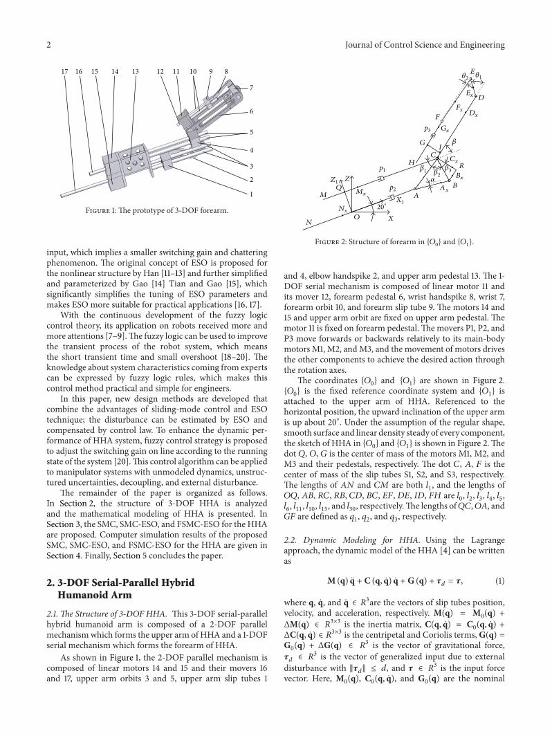
The coordinates {𝑂0} and {𝑂
1} are shown in Figure 2.
{𝑂0} is the fixed reference coordinate system and {𝑂
1} is
attached to the upper arm of HHA. Referenced to thehorizontal position, the upward inclination of the upper armis up about 20∘. Under the assumption of the regular shape,smooth surface and linear density steady of every component,the sketch of HHA in {𝑂
0} and {𝑂
1} is shown in Figure 2.The
dot 𝑄, 𝑂, 𝐺 is the center of mass of the motors M1, M2, andM3 and their pedestals, respectively. The dot 𝐶, 𝐴, 𝐹 is thecenter of mass of the slip tubes S1, S2, and S3, respectively.The lengths of 𝐴𝑁 and 𝐶𝑀 are both 𝑙
1, and the lengths of
𝑂𝑄, 𝐴𝐵, 𝑅𝐶, 𝑅𝐵, 𝐶𝐷, 𝐵𝐶, 𝐸𝐹, 𝐷𝐸, 𝐼𝐷, 𝐹𝐻 are 𝑙0, 𝑙2, 𝑙3, 𝑙4, 𝑙5,
𝑙6, 𝑙11, 𝑙10, 𝑙15, and 𝑙
30, respectively.The lengths of𝑄𝐶,𝑂𝐴, and
𝐺𝐹 are defined as 𝑞1, 𝑞2, and 𝑞
3, respectively.
2.2. Dynamic Modeling for HHA. Using the Lagrangeapproach, the dynamic model of the HHA [4] can be writtenas
M (q) q + C (q, q) q + G (q) + 𝜏𝑑 = 𝜏, (1)
where q, q, and q ∈ 𝑅3are the vectors of slip tubes position,
velocity, and acceleration, respectively. M(q) = M0(q) +
ΔM(q) ∈ 𝑅3×3 is the inertia matrix, C(q, q) = C
0(q, q) +
ΔC(q, q) ∈ 𝑅3×3 is the centripetal and Coriolis terms,G(q) =
G0(q) + ΔG(q) ∈ 𝑅
3 is the vector of gravitational force,𝜏𝑑
∈ 𝑅3 is the vector of generalized input due to external
disturbance with ‖𝜏𝑑‖ ≤ 𝑑, and 𝜏 ∈ 𝑅
3 is the input forcevector. Here, M
0(q), C
0(q, q), and G
0(q) are the nominal
Journal of Control Science and Engineering 3
parts calculated by Lagrange method, where M0(q) is a
symmetric positive definite matrix. ΔM0(q), ΔC
0(q, q), and
ΔG0(q) represent the perturbations in the system matrices.
Then the dynamic model of HHA can be rewritten as
M0(q) q + C
0(q, q) q + G
0(q) + 𝜏
𝑑+ F (q, q, q) = 𝜏,
(2)
where
F (q, q, q) = ΔM0(q) q + ΔC
0(q, q) q + ΔG
0(q) ∈ 𝑅
3
(3)
is the system uncertainty and satisfies ‖F(q, q, q)‖ ≤ 𝑏0+
𝑏1‖q‖ + 𝑏
2‖q‖2 [5, 21].
3. ESO-Based Self-Tuning Sliding-ModeControl (FSMC-ESO) for HHA
In this section, to ensure that the motion of the HHA canfollow the desired trajectory, three dynamic controllers areintroduced. First, we design a conventional sliding-modecontroller (SMC) for the HHA in the thrust level. Second,the SMC-ESO is proposed for solving the chatting problem.Finally, the FSMC-ESO is proposed to enhance the dynamicperformance and further solve the chattering problem ofHHA system. The convergence of the complete equations ofmotion of the FSMC-ESO based HHA is confirmed by theLyapunov stability theorem.
3.1. SMC Design. This section describes the SMC that isapplied to the HHA. Sliding-mode control (SMC) is oneof the effective nonlinear robust control approaches sinceit provides system dynamics with an invariance property touncertainties once the system dynamics are controlled in theslidingmode.The SMCdesign can be decoupled in two steps.The first step is the selection of an appropriate sliding surface.The second step, an approaching law, is designed so that it willdrive the system state toward sliding surface and guaranteethe stability of the system.
The realistic model (2) can be reformulated as
q = −M0
−1C0q −M
0
−1G0− d (𝑡) +M
0
−1𝜏, (4)
where d(𝑡) = M0
−1(𝜏𝑑+ F).
Assuming d(𝑡) is the upper bound of d(𝑡), then we can getd(𝑡) ≤ |d(𝑡)| ≤ d(𝑡).
For 3-DOF HHA, define the tracking error:
e = q𝑑− q, (5)
where q𝑑is the desired position trajectory of slip tubes.
The sliding surface in the space of tracking error is definedas
S = e + Ke, (6)
where S = [𝑆1, 𝑆2, 𝑆3]𝑇, K = diag[𝐾
1, 𝐾2, 𝐾3], and 𝐾
1, 𝐾2,
𝐾3> 0.
LESO
HHA
Equivalent
Slidingsurface
control
qqe s
z
qd Sign(s)Λ
3
τ
τ
eqτsw
τESO
k
Figure 3: The block diagram of the SMC-ESO.
Equivalent
HHA
LESOFuzzy
Slidingsurface
control
logic
qdΛ
3
τ
τ
eqτsw
τESOqe s
z
qk
Sign(s)
Figure 4: The block diagram of the FSMC-ESO.
Select the approaching law as
S = −Λ sgn (S) − kS, (7)
where Λ = diag[𝜆1, 𝜆2, 𝜆3], k = diag[𝑘
1, 𝑘2, 𝑘3], and 𝜆
1, 𝜆2,
𝜆3, 𝑘1, 𝑘2, 𝑘3> 0.
For the 3-DOFHHA system (4), the sliding-mode controllaw is design as
𝜏 = 𝜏eq + 𝜏sw, (8)
𝜏eq = M0q𝑑+M0Ke + C
0q + G,
𝜏sw = M0Λ sgn (S) +M
0kS,
(9)
where, 𝜏eq is equivalent control, that can make the systemstate remain on the sliding surface with no disturbance and𝜏sw is switching control, that can drive the system state to thesliding surface.
If Λ is chosen as
Λ ≥ d (𝑡) (10)
the tracking error e will asymptotically converge to zero.However, the upper bound of uncertainties, which is
required in the conventional SMC system, is difficult toobtain precisely in advance for practical applications. If theswitching gains are selected too large, the sign functionwill result in serious chattering phenomena in the controlefforts. The undesired chattering control efforts will wearthe bearing mechanism and might excite unstable systemdynamics. Hence, the ESO can be adopted here to make thetotal disturbance estimated and compensated in the controlinput, which implies the decrease of the chattering andcontrol power.
3.2. ESO-Based SMC Design. The ESO views the sys-tem model uncertainties and external disturbances as
4 Journal of Control Science and Engineering
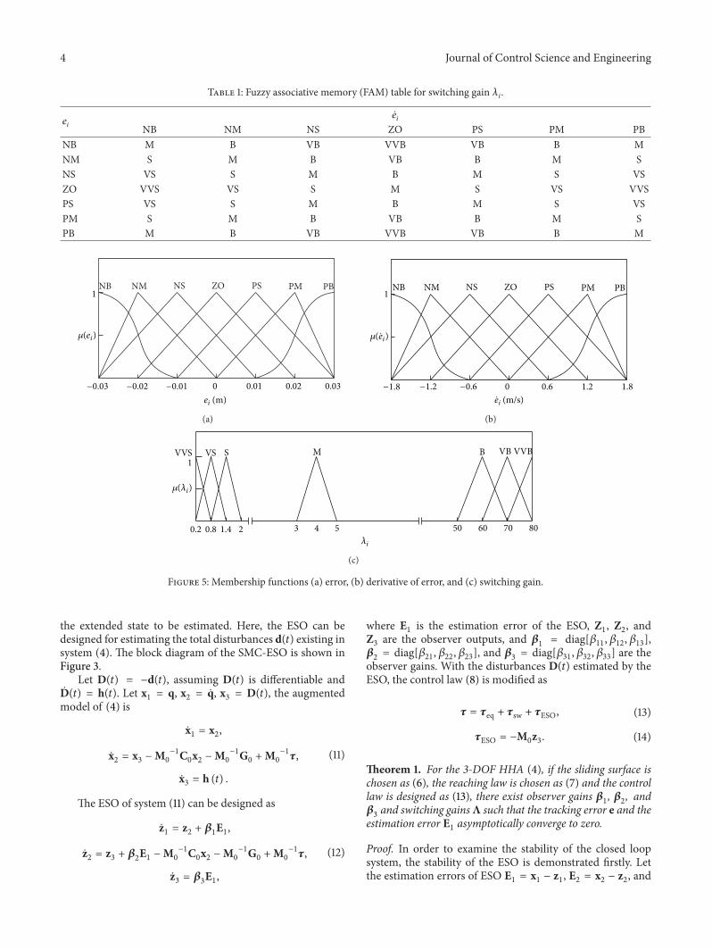
Table 1: Fuzzy associative memory (FAM) table for switching gain 𝜆𝑖.
𝑒𝑖
𝑒𝑖
NB NM NS ZO PS PM PBNB M B VB VVB VB B MNM S M B VB B M SNS VS S M B M S VSZO VVS VS S M S VS VVSPS VS S M B M S VSPM S M B VB B M SPB M B VB VVB VB B M
PBNB PMPSZONSNM1
0.020.010 0.03−0.03 −0.02 −0.01
𝜇(ei)
ei (m)
(a)
PBNB PMPSZONSNM1
1.20.60 1.8−1.8 −1.2 −0.6
𝜇( ei)
ei (m/s)
(b)
VVS VBBMSVS VVB1
0.2 70421.40.8 80605053
𝜇(𝜆i)
𝜆i
(c)
Figure 5: Membership functions (a) error, (b) derivative of error, and (c) switching gain.
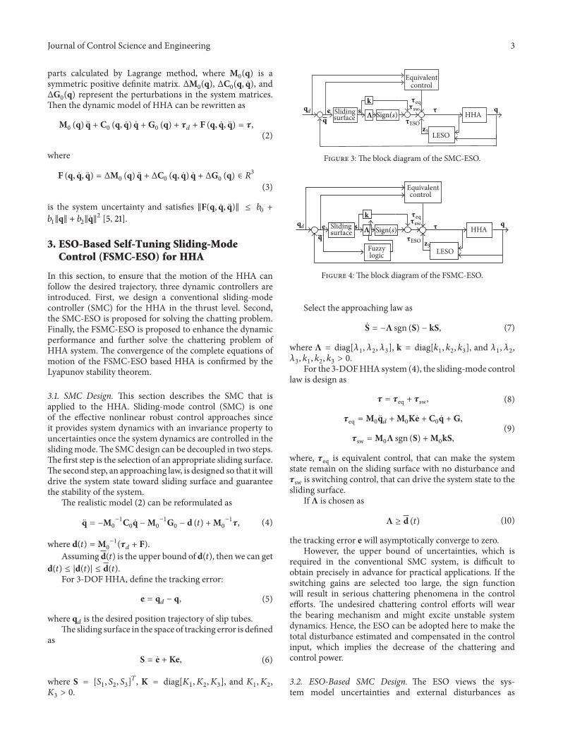
the extended state to be estimated. Here, the ESO can bedesigned for estimating the total disturbances d(𝑡) existing insystem (4). The block diagram of the SMC-ESO is shown inFigure 3.
Let D(𝑡) = −d(𝑡), assuming D(𝑡) is differentiable andD(𝑡) = h(𝑡). Let x
1= q, x
2= q, x
3= D(𝑡), the augmented
model of (4) is
x1= x2,
x2= x3−M0
−1C0x2−M0
−1G0+M0
−1𝜏,
x3= h (𝑡) .
(11)
The ESO of system (11) can be designed as
z1= z2+ 𝛽1E1,
z2= z3+ 𝛽2E1−M0
−1C0x2−M0
−1G0+M0
−1𝜏,
z3= 𝛽3E1,
(12)
where E1is the estimation error of the ESO, Z
1, Z2, and
Z3are the observer outputs, and 𝛽
1= diag[𝛽
11, 𝛽12, 𝛽13],
𝛽2= diag[𝛽
21, 𝛽22, 𝛽23], and 𝛽
3= diag[𝛽
31, 𝛽32, 𝛽33] are the
observer gains. With the disturbances D(𝑡) estimated by theESO, the control law (8) is modified as
𝜏 = 𝜏eq + 𝜏sw + 𝜏ESO, (13)
𝜏ESO = −M0z3. (14)
Theorem 1. For the 3-DOF HHA (4), if the sliding surface ischosen as (6), the reaching law is chosen as (7) and the controllaw is designed as (13), there exist observer gains 𝛽
1, 𝛽2, and
𝛽3and switching gainsΛ such that the tracking error e and the
estimation error E1asymptotically converge to zero.
Proof. In order to examine the stability of the closed loopsystem, the stability of the ESO is demonstrated firstly. Letthe estimation errors of ESO E
1= x1− z1, E2= x2− z2, and

Journal of Control Science and Engineering 5
0 1 2 3 4
0
0.01
0.02
0.03
Time (s)
Posit
ion
erro
r of S
1 (m
)
SMSM-ESOFSM-ESO
(a)
0 1 2 3 4
0
5
Time (s)
Posit
ion
erro
r of S
2 (m
)
SMSM-ESOFSM-ESO
−5
−10
−15
−20
×10−3
(b)
0 1 2 3 4
0
0.01
0.02
Time (s)
Posit
ion
erro
r of S
3 (m
)
SMSM-ESOFSM-ESO
(c)
Figure 6: (a) Position tracking error of S1, (b) position tracking error of S2, and (c) position tracking error of S3.
E3= x3− z3, then the observer error dynamics are expressed
asE1= E2− 𝛽1E1,
E2= E3− 𝛽2E1,
E3= h (𝑡) − 𝛽
3E1.
(15)
By choosing appropriate observer gains 𝛽1, 𝛽2, and 𝛽
3,
the stability of the ESO can be guaranteed and illustrated in[16]. As the observer is stable, the derivative of errors E
1= 0,
E2
= 0, and E3
= 0, then the errors of estimation can bewritten as
E1=h (𝑡)
𝛽1
,
E2= 𝛽1
h (𝑡)
𝛽2
,
E3= 𝛽2
h (𝑡)
𝛽3
.
(16)
For the 3-DOF serial-parallel hybrid humanoid arm, d(𝑡)is the upper bound of d(𝑡), even if the d(𝑡)may contain largeuncertainties, the observation error of the ESO can be downto the small enough by adjust the parameters 𝛽
1, 𝛽2, and 𝛽
3.
Thus, via tuning these parameters properly, the estimationerrors E
1, E2, and E
3can be limited to be small enough.
Having shown that the observer errors converge into theresidual set of zero, it remains to show that the closed loop
6 Journal of Control Science and Engineering
0 1 2 3 4
0
20
Time (s)
−20
z31
(t) 1
estim
atio
n (N
)D
(t)1D
(a)
0 1 2 3 4
0
50
100
Time (s)
−50
z32
(t) 2
estim
atio
n (N
)D
(t)2D
(b)
0 1 2 3 4
0
20
Time (s)
−20
(t) 3
estim
atio
n (N
)
(t)3z33
D
D
(c)
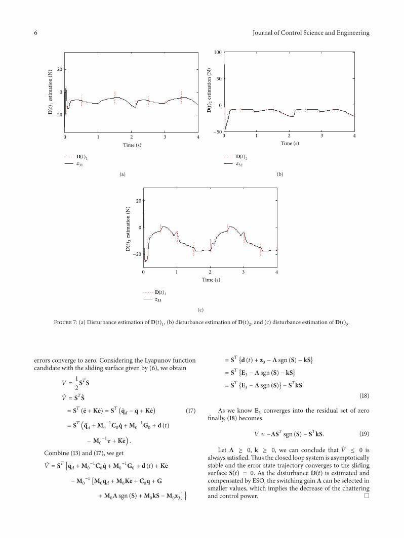
Figure 7: (a) Disturbance estimation of D(𝑡)1, (b) disturbance estimation ofD(𝑡)
2, and (c) disturbance estimation ofD(𝑡)
3.
errors converge to zero. Considering the Lyapunov functioncandidate with the sliding surface given by (6), we obtain
𝑉 =1
2S𝑇S
�� = S𝑇S
= S𝑇 (e + Ke) = S𝑇 (q𝑑− q + Ke)
= S𝑇 (q𝑑+M0
−1C0q +M
0
−1G0+ d (𝑡)
− M0
−1𝜏 + Ke) .
(17)
Combine (13) and (17), we get
�� = S𝑇 {q𝑑+M0
−1C0q +M
0
−1G0+ d (𝑡) + Ke
−M0
−1[M0q𝑑+M0Ke + C
0q + G
+ M0Λ sgn (S) +M
0kS −M
0z3] }
= S𝑇 {d (𝑡) + z3− Λ sgn (S) − kS}
= S𝑇 {E3− Λ sgn (S) − kS}
= S𝑇 {E3− Λ sgn (S)} − S𝑇kS.
(18)
As we know E3converges into the residual set of zero
finally, (18) becomes
�� ≈ −ΛS𝑇 sgn (S) − S𝑇kS. (19)
Let Λ ≥ 0, k ≥ 0, we can conclude that �� ≤ 0 isalways satisfied.Thus the closed loop system is asymptoticallystable and the error state trajectory converges to the slidingsurface S(𝑡) = 0. As the disturbance D(𝑡) is estimated andcompensated by ESO, the switching gainΛ can be selected insmaller values, which implies the decrease of the chatteringand control power.
Journal of Control Science and Engineering 7
0 1 2 3 4
0
20
40
60
Time (s)
Adap
tive g
ain
1
(a)
0 1 2 3 4
0
20
40
60
Time (s)
Adap
tive g
ain
2
(b)
0 1 2 3 4
0
20
40
60
Time (s)
Adap
tive g
ain
3
(c)
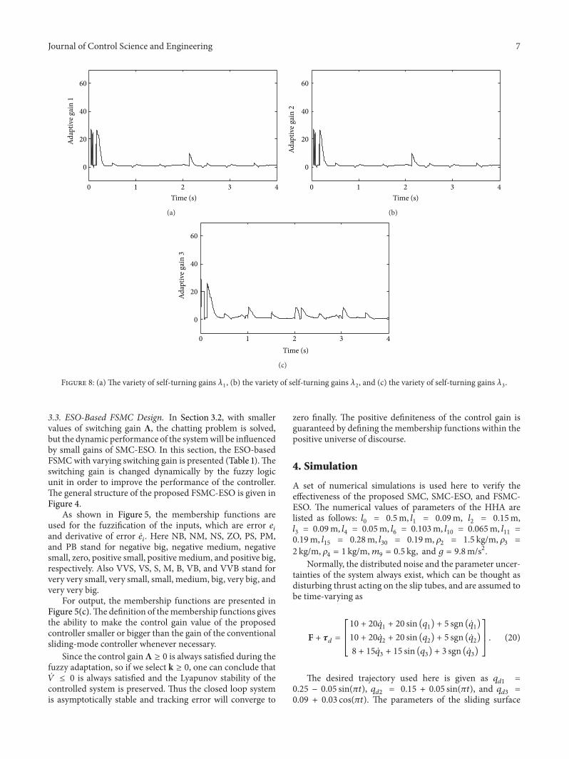
Figure 8: (a) The variety of self-turning gains 𝜆1, (b) the variety of self-turning gains 𝜆
2, and (c) the variety of self-turning gains 𝜆
3.
3.3. ESO-Based FSMC Design. In Section 3.2, with smallervalues of switching gain Λ, the chatting problem is solved,but the dynamic performance of the systemwill be influencedby small gains of SMC-ESO. In this section, the ESO-basedFSMCwith varying switching gain is presented (Table 1).Theswitching gain is changed dynamically by the fuzzy logicunit in order to improve the performance of the controller.The general structure of the proposed FSMC-ESO is given inFigure 4.
As shown in Figure 5, the membership functions areused for the fuzzification of the inputs, which are error 𝑒
𝑖
and derivative of error 𝑒𝑖. Here NB, NM, NS, ZO, PS, PM,
and PB stand for negative big, negative medium, negativesmall, zero, positive small, positive medium, and positive big,respectively. Also VVS, VS, S, M, B, VB, and VVB stand forvery very small, very small, small, medium, big, very big, andvery very big.
For output, the membership functions are presented inFigure 5(c).The definition of themembership functions givesthe ability to make the control gain value of the proposedcontroller smaller or bigger than the gain of the conventionalsliding-mode controller whenever necessary.
Since the control gainΛ ≥ 0 is always satisfied during thefuzzy adaptation, so if we select k ≥ 0, one can conclude that�� ≤ 0 is always satisfied and the Lyapunov stability of thecontrolled system is preserved. Thus the closed loop systemis asymptotically stable and tracking error will converge to
zero finally. The positive definiteness of the control gain isguaranteed by defining the membership functions within thepositive universe of discourse.
4. Simulation
A set of numerical simulations is used here to verify theeffectiveness of the proposed SMC, SMC-ESO, and FSMC-ESO. The numerical values of parameters of the HHA arelisted as follows: 𝑙
0= 0.5m, 𝑙
1= 0.09m, 𝑙
2= 0.15m,
𝑙3
= 0.09m, 𝑙4
= 0.05m, 𝑙6
= 0.103m, 𝑙10
= 0.065m, 𝑙11
=
0.19m, 𝑙15
= 0.28m, 𝑙30
= 0.19m, 𝜌2
= 1.5 kg/m, 𝜌3
=
2 kg/m, 𝜌4= 1 kg/m,𝑚
9= 0.5 kg, and 𝑔 = 9.8m/s2.
Normally, the distributed noise and the parameter uncer-tainties of the system always exist, which can be thought asdisturbing thrust acting on the slip tubes, and are assumed tobe time-varying as
F + 𝜏𝑑=
[[
[
10 + 20 𝑞1+ 20 sin (𝑞
1) + 5 sgn ( 𝑞
1)
10 + 20 𝑞2+ 20 sin (𝑞
2) + 5 sgn ( 𝑞
2)
8 + 15 𝑞3+ 15 sin (𝑞
3) + 3 sgn ( 𝑞
3)
]]
]
. (20)
The desired trajectory used here is given as 𝑞𝑑1
=
0.25 − 0.05 sin(𝜋𝑡), 𝑞𝑑2
= 0.15 + 0.05 sin(𝜋𝑡), and 𝑞𝑑3
=
0.09 + 0.03 cos(𝜋𝑡). The parameters of the sliding surface
8 Journal of Control Science and Engineering
−500
0
0
1 2 3 4
0
500
1000
Time (s)
Thru
st of
M1
(N)
SMSM-ESOFSM-ESO
(a)
−200
−4000 1 2 3 4
0
200
400
600
800
Time (s)
Thru
st of
M2
(N)
SMSM-ESOFSM-ESO
(b)
0 1 2 3 4
0
50
100
150
200
Time (s)
Thru
st of
M3
(N)
SMSM-ESOFSM-ESO
−50
(c)
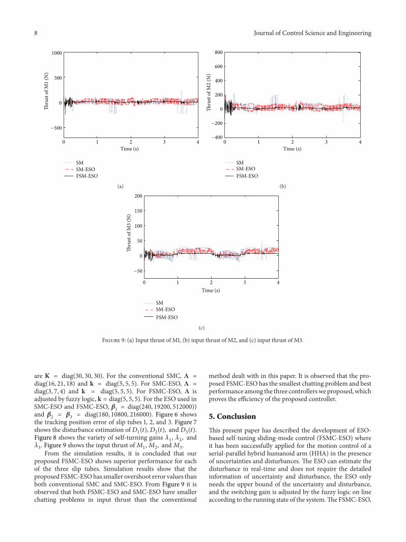
Figure 9: (a) Input thrust of M1, (b) input thrust of M2, and (c) input thrust of M3.
are K = diag(30, 30, 30). For the conventional SMC, Λ =
diag(16, 21, 18) and k = diag(5, 5, 5). For SMC-ESO, Λ =
diag(3, 7, 4) and k = diag(5, 5, 5). For FSMC-ESO, Λ isadjusted by fuzzy logic, k = diag(5, 5, 5). For the ESO used inSMC-ESO and FSMC-ESO, 𝛽
1= diag(240, 19200, 512000))
and 𝛽2
= 𝛽3
= diag(180, 10800, 216000). Figure 6 showsthe tracking position error of slip tubes 1, 2, and 3. Figure 7shows the disturbance estimation of𝐷
1(𝑡),𝐷
2(𝑡), and𝐷
3(𝑡).
Figure 8 shows the variety of self-turning gains 𝜆1, 𝜆2, and
𝜆3. Figure 9 shows the input thrust of𝑀
1,𝑀2, and𝑀
3.
From the simulation results, it is concluded that ourproposed FSMC-ESO shows superior performance for eachof the three slip tubes. Simulation results show that theproposed FSMC-ESOhas smaller overshoot error values thanboth conventional SMC and SMC-ESO. From Figure 9 it isobserved that both FSMC-ESO and SMC-ESO have smallerchatting problems in input thrust than the conventional
method dealt with in this paper. It is observed that the pro-posed FSMC-ESO has the smallest chatting problem and bestperformance among the three controllerswe proposed,whichproves the efficiency of the proposed controller.
5. Conclusion
This present paper has described the development of ESO-based self-tuning sliding-mode control (FSMC-ESO) whereit has been successfully applied for the motion control of aserial-parallel hybrid humanoid arm (HHA) in the presenceof uncertainties and disturbances. The ESO can estimate thedisturbance in real-time and does not require the detailedinformation of uncertainty and disturbance, the ESO onlyneeds the upper bound of the uncertainty and disturbance,and the switching gain is adjusted by the fuzzy logic on lineaccording to the running state of the system.The FSMC-ESO,
Journal of Control Science and Engineering 9
with the advantages of SMC, ESO, and parameter self-tuning strategy, has shown a significant improvement over theconventional SMC under the same conditions. Meanwhile,the chattering phenomenon that frequently appears in theconventional SMC is also weakened by the fuzzy control.Theeffectiveness of the designed FSMC-ESO strategy was illus-trated by simulation examples.
Conflict of Interests
The authors declare that there is no conflict of interestsregarding the publication of this paper.
References
[1] Y. Wang, R. Shi, and H. Wang, “Dynamic modeling andfuzzy self-tuning disturbance decoupling control for a 3-DOFserial-parallel hybrid humanoid arm,” Advances in MechanicalEngineering, vol. 2013, Article ID 286074, 14 pages, 2013.
[2] Y. Wang and Z. Jin, “Dynamics modeling and robust trajectorytracking control for a class of hybrid humanoid arm based onneural network,”Chinese Journal ofMechanical Engineering, vol.22, no. 3, pp. 355–363, 2009.
[3] S. Yu, X. Yu, B. Shirinzadeh, and Z. Man, “Continuous finite-time control for robotic manipulators with terminal slidingmode,” Automatica, vol. 41, no. 11, pp. 1957–1964, 2005.
[4] M. B. R. Neila and D. Tarak, “Adaptive terminal sliding modecontrol for rigid robotic manipulators,” International Journal ofAutomation and Computing, vol. 8, no. 2, pp. 215–220, 2011.
[5] T. Sun, H. Pei, Y. Pan, H. Zhou, and C. Zhang, “Neural network-based sliding mode adaptive control for robot manipulators,”Neurocomputing, vol. 74, no. 14-15, pp. 2377–2384, 2011.
[6] C. Chen, T. S. Li, Y. Yeh, and C. Chang, “Design and imple-mentation of an adaptive sliding-mode dynamic controller forwheeledmobile robots,”Mechatronics, vol. 19, no. 2, pp. 156–166,2009.
[7] E. Kayacan, H. Ramon, and W. Saeys, “Adaptive neuro-fuzzycontrol of a spherical rolling robot using sliding-mode-control-theory-based online learning algorithm,” IEEE Transactions onSystems, Man, and Cybernetics B: Cybernetics, vol. 43, 170, no. 1,p. 179, 2013.
[8] T. S. Li and Y. C. Huang, “MIMO adaptive fuzzy terminalsliding-mode controller for robotic manipulators,” InformationSciences, vol. 180, no. 23, pp. 4641–4660, 2010.
[9] N. Yagiz and Y. Hacioglu, “Robust control of a spatial robotusing fuzzy sliding modes,” Mathematical and Computer Mod-elling, vol. 49, no. 1-2, pp. 114–127, 2009.
[10] Q. Zheng, Z. Chen, and Z. Gao, “A practical approach todisturbance decoupling control,” Control Engineering Practice,vol. 17, no. 9, pp. 1016–1025, 2009.
[11] J. Han, “Auto-disturbance rejection control and its applications,”Control and Decision, vol. 13, no. 1, pp. 19–23, 1998 (Chinese).
[12] J. Han, “A class of extended state observers for uncertainsystems,” Control and Decision, vol. 10, no. 1, pp. 85–88, 1995(Chinese).
[13] J. Han, “FromPID to active disturbance rejection control,” IEEETransactions on Industrial Electronics, vol. 56, no. 3, pp. 900–906, 2009.
[14] Z. Gao, “Scaling and parameterization based controller tuning,”in Proceedings of the American Control Conference, vol. 6, pp.4989–4996, 2003.
[15] G. Tian and Z. Gao, “Frequency response analysis of activedisturbance rejection based control system,” in Proceedings ofthe 16th IEEE International Conference on Control Applications(CCA ’07), pp. 1595–1599, October 2007.
[16] Y. Xia, Z. Zhu, M. Fu, and S. Wang, “Attitude tracking of rigidspacecraft with bounded disturbances,” IEEE Transactions onIndustrial Electronics, vol. 58, no. 2, pp. 647–659, 2011.
[17] Z. Zhu, Y. Xia, M. Fu, and S. Wang, “An observer-based missileguidance law,” inProceedings of the Chinese Control andDecisionConference (CCDC '11), pp. 1282–1287, Mianyang, China, May2011.
[18] G. K. I.Mann, B.Hu, andR.G.Gosine, “Analysis of direct actionfuzzy PID controller structures,” IEEE Transactions on Systems,Man, and Cybernetics B: Cybernetics, vol. 29, no. 3, pp. 371–388,1999.
[19] J. Carvajal, G. Chen, and H. Ogmen, “Fuzzy PID controller:design, performance evaluation, and stability analysis,” Infor-mation Sciences, vol. 123, no. 3-4, pp. 249–270, 2000.
[20] H. B. Kazemian, “Comparative study of a learning fuzzy PIDcontroller and a self-tuning controller,” ISA Transactions, vol.40, no. 3, pp. 245–253, 2001.
[21] M. Zhihong and X. Yu, “Adaptive terminal sliding modetracking control for rigid robotic manipulators with uncertaindynamics,” JSME International Journal C: Mechanical Systems,Machine Elements and Manufacturing, vol. 40, no. 3, pp. 493–502, 1997.

International Journal of
AerospaceEngineeringHindawi Publishing Corporationhttp://www.hindawi.com Volume 2014
RoboticsJournal of
Hindawi Publishing Corporationhttp://www.hindawi.com Volume 2014
Hindawi Publishing Corporationhttp://www.hindawi.com Volume 2014
Active and Passive Electronic Components
Control Scienceand Engineering
Journal of
Hindawi Publishing Corporationhttp://www.hindawi.com Volume 2014
International Journal of
RotatingMachinery
Hindawi Publishing Corporationhttp://www.hindawi.com Volume 2014
Hindawi Publishing Corporation http://www.hindawi.com
Journal ofEngineeringVolume 2014
Submit your manuscripts athttp://www.hindawi.com
VLSI Design
Hindawi Publishing Corporationhttp://www.hindawi.com Volume 2014
Hindawi Publishing Corporationhttp://www.hindawi.com Volume 2014
Shock and Vibration
Hindawi Publishing Corporationhttp://www.hindawi.com Volume 2014
Civil EngineeringAdvances in
Acoustics and VibrationAdvances in
Hindawi Publishing Corporationhttp://www.hindawi.com Volume 2014
Hindawi Publishing Corporationhttp://www.hindawi.com Volume 2014
Electrical and Computer Engineering
Journal of
Advances inOptoElectronics
Hindawi Publishing Corporation http://www.hindawi.com
Volume 2014
The Scientific World JournalHindawi Publishing Corporation http://www.hindawi.com Volume 2014
SensorsJournal of
Hindawi Publishing Corporationhttp://www.hindawi.com Volume 2014
Modelling & Simulation in EngineeringHindawi Publishing Corporation http://www.hindawi.com Volume 2014
Hindawi Publishing Corporationhttp://www.hindawi.com Volume 2014
Chemical EngineeringInternational Journal of Antennas and
Propagation
International Journal of
Hindawi Publishing Corporationhttp://www.hindawi.com Volume 2014
Hindawi Publishing Corporationhttp://www.hindawi.com Volume 2014
Navigation and Observation
International Journal of
Hindawi Publishing Corporationhttp://www.hindawi.com Volume 2014
DistributedSensor Networks
International Journal of