a fuzzy sliding mode controller for a field-oriented...
TRANSCRIPT

160
A Fuzzy Sliding Mode Controller for a Field-Oriented
Induction Motor Drive
Dr K B Mohanty Member Department of Electrical Engineering National Institute of Technology Rourkela India
This paper presents a robust control technique for a field oriented induction motor drive Sliding Mode Controller (SMC) and Fuzzy Sliding
Mode Controller (FSMC) are designed for the speed loop of the drive The design steps for both the controllers are laid down clearly The
FSMC uses three-level input membership sets and five-level output membership set of symmetrical triangular shape nine fuzzy rules and
the Center-of-Gravity defuzzification technique The performance of the Fuzzy Sliding Mode Controller has been evaluated through
simulation studies with respect to the conventional sliding mode controller The chattering free improved performance of the FSMC makes
it superior to conventional SMC and establishes its suitability for the induction motor drive
Keywords Field oriented control Sliding mode controller Fuzzy sliding mode controller
NOTATIONS vds ( vqs) the d-axis (q-axis) stator voltage
ids ( iqs) the d-axis (q-axis) stator current
)ψ(ψ qrdr the d-axis (q-axis) rotor flux linkage
rω mechanical rotor angular velocity
eω fundamental supply frequency
P number of pole pairs
KT torque constant
Te developed torque
TL load torque
J moment of inertia of rotor with load
β viscous friction coefficient (Nmiddotmmiddotsrad)
λ bandwidth of the sliding mode control system
η a positive constant
maxG∆ maximum error in estimation of G
v upper bound of command acceleration
Kmax gain of the sliding mode controller
KN (or KFuzz|N) the fuzzy value of the controller gain
N|FuzzK defuzzified value of the controller gain
outmicro degree of membership of output as a function
of the fuzzy value of output denotes command or reference value
INTRODUCTION
Induction motors fulfill the de facto industrial
standard because of their simple and robust structure
higher torque-to-weight ratio higher reliability and
ability to operate in hazardous environment However
because of the coupling between torque and flux
unlike dc motor their control is a challenging task
One of the classical methods of induction motor
control by now is the field-oriented control1 It leads
to decoupling between the flux and torque thus
resulting in improved dynamic response of torque and
speed But ideal field orientation is obtained if the
machine parameters are accurately known under all
conditions If the machine parameters used in the
decoupling control scheme can not track their true
Dr K B Mohanty is with Electrical Engineering Department
National Institute of Technology Rourkela 769008 This paper was received on December 27 2004 Written
discussions on the paper will be entertained till February 28 2006
values the efficiency of the motor drive is degraded
owing to reduction of torque generating capability and
magnetic saturation caused by over excitation The
dynamic control characteristic is also degraded In
addition to this parameter detuning problem the load
torque disturbance and measurement noise also make
a robust control technique mandatory to meet the
standards of a high performance drive
To improve the field oriented control of induction
motor under the above mentioned problems and to
track complex position and torque trajectories sliding
mode control2-5
has been proposed A sliding mode
speed controller2 based on a switching surface is
demonstrated With this switching surface the
stability is guaranteed for the speed control and
insensitivity to uncertainties and disturbances is also
obtained Sliding mode control3 is applied to position
control loop of an indirect vector controlled induction
motor drive without rotor resistance identification
scheme Results are compared with a fixed gain
controller A sliding mode based adaptive input-
output linearizing control4 is presented The motor
flux and speed are separately controlled by sliding
mode controllers with variable switching gains A
sliding mode controller with rotor flux estimation5 is
presented Rotor flux is also estimated using a sliding
mode observer The results are compared with a field
oriented controller and an input-output linearizing
controller
Fuzzy logic controller is also used6 for solving the
parameter detuning problem of indirect vector
controlled induction motor drive A fuzzy slip speed
estimator7 consisting of a fuzzy detuning correction
controller and a fuzzy excitation controller is
presented for improving the decoupling
characteristics of the drive An on-line fuzzy tuning
technique8 is proposed for indirect field oriented
induction motor drive It has also been proved9 that
in principle certain type of fuzzy logic controller
works like a modified sliding mode controller Fuzzy
logic controller and sliding mode controller are
combined to formulate the fuzzy sliding mode
controller9 whose application potential is yet to be
explored This fuzzy sliding mode controller is
expected to be a robust control technique like both
sliding mode and fuzzy logic controllers while being
free of the demerit of sliding mode controller namely
161
the chattering of the control input and some of the
system states
This paper investigates the applicability of fuzzy
sliding mode controller9 to a field oriented induction
motor drive Systematic procedure is developed to
design sliding mode controller and fuzzy sliding
mode controller and a comparative study is carried
out between the two
FIELD ORIENTED INDUCTION MOTOR
The dynamic equations of the induction motor in the
synchronously rotating d-q reference frame with
stator current and rotor flux components as variables
are considered The mathematical constraint for field
orientated control is
0ψqr = and 0ψqr =amp (1)
Equation (1) is satisfied and field orientation is
obtained when
drqs5re ψiaωPω += (2)
When eqn (2) is satisfied the dynamic behavior of
the induction motor is
dsqsedr2ds1ds vciωψaiai +++minus=amp (3)
qsdrr3qs1dseqs cvψωPaiaiωi +minusminusminus=amp (4)
ds5dr4dr iaψaψ +minus=amp (5)
qsdrTe iKT ψ= (6)
where )LLL(Lc 2mrsr minus=
2r
2mrs1 LLRcRca +=
2rmr2 LLRca = rm3 LLca =
rr4 LRa = rmr5 LLRa =
Ideally torque and flux are decoupled under the
above condition resulting in field orientation
However due to the presence of the motor parameter
a5 in eqn (2) the indirect field oriented control is
highly parameter sensitive On-line adaptation to
achieve ideal field orientation is an important but
very difficult issue Sliding mode control10
is a good
robust control technique against parameter detuning
problem But it has the demerit namely chattering of
control input and some of the system states Fuzzy
sliding mode control9 is also a robust control
technique like sliding mode control and it does not
have the above demerit The following sections
present the design principles of a sliding mode
controller (SMC) and a fuzzy sliding mode controller
(FSMC) based on the motor eqns (1) to (6) Their
comparative study for the induction motor drive has
been carried out
DESIGN OF SLIDING MODE
CONTROLLER
In sliding mode control the system is controlled in
such a way that the error in the system state (say
speed) always moves towards a sliding surface The
sliding surface (s) is defined with the tracking error
(e) of the state and its rate of change ( eamp) as variables
eλes += amp (7)
The distance of the error trajectory from the sliding
surface and its rate of convergence are used to decide
the control input The sign of the control input must
change at the intersection of tracking error trajectory
with the sliding surface In this way the error
trajectory is forced to move always towards the
sliding surface Once it reaches the sliding surface
the system is constrained to slide along this surface to
the equilibrium point The condition of sliding mode10
is
η)ssgn(s minuslesdotamp (8)
To design a sliding mode speed controller for the
field oriented induction motor drive system the steps
are as follows The speed dynamic equations are
given by
)JT(gω L1r +=amp (9)
and duGωr ++=ampamp (10)
where u is the control input given by
JcψKu qsdrT v= (11)
G is a function which can be estimated from
measured values of currents and speed
J)gψKgβ(G 2drT1 +minus= (12)
J)iψKωβ(g qsdrTr1 +minus=
dsm3rqs412 i)La(1ωPi)a(ag +minus+minus=
In eqn (10) d is the disturbance due to the load
torque and error in estimation of G which may occur
due to measurement inaccuracies
Substituting (7) and (10) in (8) and
simplifying
η)ssgn(u)ssgn()ωeλdG( r minuslesdot+minus++ ampampamp
(13)
To achieve the sliding mode of (8) u is chosen as10
)ssgn(K)eλG(u sdotminusminusminus= amp (14)
The first term in (14) )eG( ampλminusminus is a
compensation term and the second term is the
controller The compensation term is continuous and
reflects knowledge of the system dynamics The
controller term is discontinuous and ensures the
sliding to occur From eqns (13-14) the controller
gain K is derived as10
)vη|d||G(|K maxmaxmax +++∆ge (15)
The controller gain K is determined using (15) and
considering various conditions such as
(i) increase in stator and rotor resistance due to
temperature rise
(ii) change in load torque
(iii) variation in the reference speed
For the induction motor whose rating and parameters
are given in Table-1 taking a typical case as (i) 50
162
increase in stator and rotor resistance (ii) change in
load torque by 10 Nsdotm in 50 ms (rated torque is 5
Nsdotm) (iii) 50 change in reference (base) speed in
50 ms the controller gain Kmax is obtained as
Kmax = 56000 rads3
In a system where modelling imperfection parameter
variations and amount of noise are more the value of
K must be large to obtain a satisfactory tracking
performance But larger value of K leads to more
chattering of the control variable and system states
To reduce chattering a boundary layer of width φ is
introduced on both sides of the switching line Then
the control law of (14) is modified as
)φssat(KeλGu sdotminusminusminus= amp (16)
where
gt
le=
φ|s|if)ssgn(
φ|s|ifφs)φ(ssat
This amounts to a reduction of the control gain inside
the boundary layer and results in a smooth control
signal The tracking precision is given by
λφθ = (17)
To have a tracking precision θ = 1 rads
λλθφ ==
2max λλφK == (18)
3max 10056Kλ times== = 2366 rads (18)
and == λθφ 2366 rads2
Table ndash 1 Rating and Parameters of the Induction Motor
Three phase 50 Hz 075 kW 220V 3A 1440 rpm
Stator and rotor resistances Rs = 637 Ω Rr = 43 Ω
Stator and rotor self inductances Ls = Lr = 026 H
Mutual inductance between stator and rotor Lm = 024 H
Moment of Inertia of motor and load J = 00088 Kg middotm2
Viscous friction coefficient β = 0003 N middotm middotsrad
DESIGN OF FUZZY SLIDING MODE
CONTROLLER
The fuzzy sliding mode controller (FSMC) explained
here is a modification of the sliding mode controller
(eqn (14)) where the switching controller term minus K sdot sgn(s) has been replaced by a fuzzy control input as
given below
Fuzzu)eλG(u +minusminus= amp (19)
and Fuzzu = minus )λee(K Fuzz amp sgn(s) (20)
The gain KFuzz of the controller is determined from
fuzzy rules The qualitative rules of the fuzzy sliding
mode controller are as follows
bull The normalized fuzzy output uFuzz|N should be
negative above the switching line and positive
below it
bull |uFuzz|N| should increase as the distance d1
between the actual state and the switching line s
= 0 increases The distance d1 is given by
22
1
1
|ee|
1
|s|d
λ
λ
λ +
+=
+
=amp
(21)
bull |uFuzz|N| should increase as the distance d2
between the actual state and the line
perpendicular to the switching line increases The
distance d2 between the actual state and the line
perpendicular to the switching line is
21
222 deed minus+= amp (22)
The reasons for this rule to be followed are
(a) the discontinuities at the boundaries of
the phase plane are avoided
(b) the central domain of the phase plane
is arrived at very quickly
bull Normalized states NN ee amp that fall out of the
phase plane should be covered by the maximum
values maxN|Fuzz |u| with the respective sign
of uFuzz|N
The normalized distances d1N and d2N are
d1N = N1 d1 and d2N = N2 d2
where N1 and N2 are the normalization factors
These normalized inputs (d1N and d2N) to the fuzzy
controller are fuzzified by a three member fuzzy set
Z Zero P Positive LP Large Positive
The fuzzy set for normalized controller gain (output
of the fuzzy controller) KFuzz|N (also denoted as KN
for brevity) is Z Zero SP
Small Positive MP Medium Positive
The membership functions for the normalized inputs
are shown in Fig1(a) and those for the normalized
output are shown in Fig1(b) Linear and symmetrical
membership functions are used for ease of realization
Only three-member input sets and five-member output
set are chosen based on engineering experience so as
to have approximately linear transfer characteristics
without sacrificing simplicity of the controller The
rule base for the fuzzy controller consisting of nine
rules is listed in Table-2
Table ndash 2 Fuzzy rule base
d1N
d2N
Z P LP
Z Z SP MP
P SP MP LP
LP MP LP VLP
The inference engine performs fuzzy implications
and computes the degree of membership of the output
(normalized controller gain) in each fuzzy set using
Zadeh AND and OR operations Then defuzzification
is carried out by the Center-of-Gravity method as
given in eqn (23)
163
int sdot
int sdotsdot
=1
0Nout
1
0NNout
N|Fuzz
dKmicro
dKKmicro
K (23)
The defuzzified value N|FuzzK is denormalized
with respect to the corresponding physical domain
KFuzz by the denormalization factor Nu
max|N|Fuzz
max|Fuzzu
K
KN = (24)
where max|N|FuzzK is the maximum value of
defuzzified (but normalized) controller gain and
KFuzz|max is the maximum value of the controller gain
KFuzz
Since the sliding mode controller and the fuzzy
sliding mode controller described in this paper are
structurally similar the maximum gain KFuzz|max is
taken equal to the gain of the sliding mode controller
Kmax so that comparison of both can be made under
similar conditions
KFuzz|max = 56000 rads3
For N1 = N2 = 008 (fixed by engineering judgment
and experience) and the above value of KFuzz|max the
denormalization factor Nu = 110000
RESULTS AND DISCUSSIONS
The 3-phase induction motor drive system whose
rating and parameters are given in Table-1 is
subjected to various simulation tests with both the
above controllers The simulation study is carried out
with a ramp (linear) change in reference speed The
reference speed is linearly increased from 1000 rmin
to 1500 rmin in 50 ms ie at a rate 10 (rmin)ms
The reference d-axis rotor flux linkage is kept at 045
Vsdots and load torque is kept at zero The simulation
responses of the drive system with sliding mode
controller (SMC) are shown in Fig 2 and those with
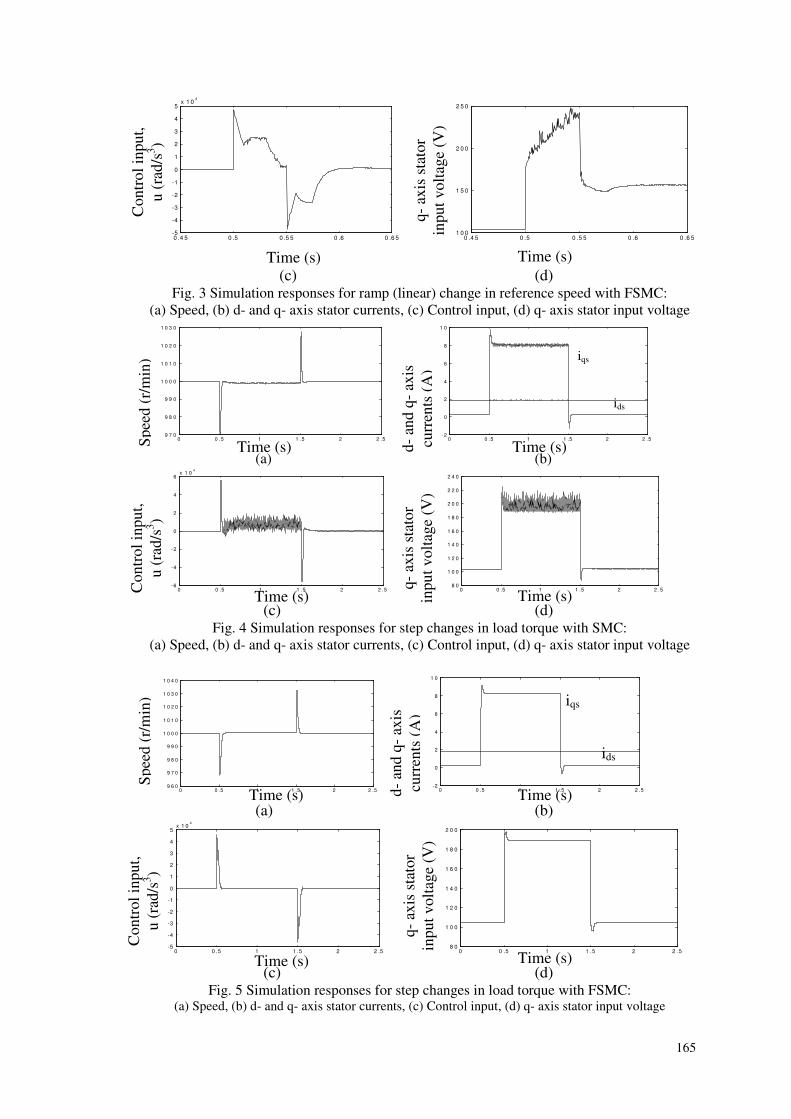
fuzzy sliding mode controller (FSMC) are shown in
Fig 3 Though the responses with FSMC are
generally similar to those with SMC the speed
response has an overshoot of 28 rmin with SMC but
no overshoot is present with FSMC The q-axis stator
voltage increases from initial steady state value of 104
V to final steady state value of 156 V with a peak
value of 255 V in SMC and 245 V in FSMC during
the transient period The control input (u) has
chattering in SMC but is free of chattering in FSMC
The q-axis component of stator voltage and current
are only affected as they control the torque and hence
speed The field orientation is obvious as the d-axis
stator current and rotor flux remain constant
To see the chattering-free robust responses of FSMC
the load torque is suddenly increased from 0 to 10
Nm (rated torque is 5 Nm) and then the load is
removed after 1 sec With both SMC (Fig 4) and
FSMC (Fig 5) there is an instantaneous speed change
of 30 rmin during the change of load But the drive
system recovers to the reference speed of 1000 rmin
almost instantaneously With SMC the response of
current (iqs) the q-axis stator input voltage (vqs) and
the control input (u) have chattering during the load
period But no such chattering is present in case of
FSMC
CONCLUSIONS
Sliding mode and fuzzy sliding mode controllers are
designed for a field oriented induction motor drive to
have the same maximum controller gain From the
simulation study of both the controllers it is observed
that the control input the stator input voltage and
some of the states like speed and stator current have
chattering with sliding mode controller whereas these
are free of chattering with fuzzy sliding mode
controller For the same maximum gain with both the
controllers the speed response is also nearly the same
(slightly better in FSMC than SMC) and the stator
input voltage is less in case of FSMC compared to
SMC In other words with fuzzy sliding mode
controller the maximum gain can be increased at the
cost of increased stator input voltage leading to better
speed response So for chattering-free robust control
of field oriented induction motor drive fuzzy sliding
mode controller is a better choice than sliding mode
controller The number of members in the input and
output sets of the fuzzy controller can be increased so
also the number of rules in the fuzzy rule base so as
to closely approximate the linear transfer
characteristics within the boundary layer This would
give better performance of the controller at the cost of
increased computational time
REFERENCES
1 F Blaschke ldquoThe principle of field orientation as
applied to the new transvektor closed-loop system for
rotating-field machinesrdquo Siemens Review vol 39 no
5 May 1970 pp 217-220
2 K K Shyu and H J Shieh ldquoA new switching surface
sliding mode speed control for induction motor drive
systemsrdquo IEEE Trans on Power Electronics vol 11
no 4 1996 pp 660-667
3 M W Dunnigan S Wade B W Williams and X
Xu ldquoPosition control of a vector controlled induction
machine using Slotinersquos sliding mode control
approachrdquo IEE Proc on Elect Power Appl vol 145
no 3 May 1998 pp 231-238
4 T G Park and K S Lee ldquoSMC-based adaptive input-
output linearizing control of induction motorsrdquo IEE
Proc on Control Theory Applications vol 145 no 1
Jan 1998 pp 55-62
5 A Benchaib A Rachid and E Audrezet ldquo Sliding
mode input-output linearization and field orientation
for real-time control of induction motorsrdquo IEEE Trans
on Power Electronics vol 14 no 1 Jan 1999 pp 3-
13
6 G C D Sousa B K Bose and K S Kim ldquo Fuzzy
logic based on-line MRAC tuning of slip gain for an
indirect vector controlled induction motor driverdquo IEEE
164
Conf record IAS annual meeting 1993 pp 1003-
1008
7 J B Wang and C M Liaw ldquoPerformance
improvement of a field-oriented induction motor drive
via fuzzy controlrdquo Electric Machines and Power
Systems vol 27 no 1 1999 pp 93-105
8 L Zhen and L Xu ldquoOn-line fuzzy tuning of indirect
field-oriented induction machine drivesrdquo IEEE Trans
on Power Electronics vol 13 no 1 Jan 1998 pp
134-141
9 R Palm ldquoRobust Control by Fuzzy Sliding Moderdquo
Automatica vol 30 no 9 1994 pp 1429-1437
10 Slotine J J E and W Li Applied Nonlinear Control
Prentice Hall Inc Englewood Cliffs NJ 1991
0
05
1
0 05 1
0
05
1
0 025 05 075 1 125
(a) (b)
Fig 1 Membership functions for (a) normalized inputs (b) normalized output
0 4 5 0 5 0 5 5 0 6 0 6 5
9 0 0
1 0 0 0
1 1 0 0
1 2 0 0
1 3 0 0
1 4 0 0
1 5 0 0
1 6 0 0
0 4 5 0 5 0 5 5 0 6 0 6 5-2
0
2
4
6
8
1 0
(a) (b)
0 4 5 0 5 0 5 5 0 6 0 6 5-6
-4
-2
0
2
4
6x 1 0
4
0 4 5 0 5 0 5 5 0 6 0 6 5
1 0 0
1 2 0
1 4 0
1 6 0
1 8 0
2 0 0
2 2 0
2 4 0
2 6 0
(c) (d) Fig 2 Simulation responses for ramp (linear) change in reference speed with SMC
(a) Speed (b) d- and q- axis stator currents (c) Control input (d) q- axis stator input voltage
0 4 5 0 5 0 55 0 6 0 65
9 00
10 00
11 00
12 00
13 00
14 00
15 00
16 00
0 4 5 0 5 0 5 5 0 6 0 6 5-1
0
1
2
3
4
5
6
7
8
9
(a) (b)
Time (s)
Sp
eed
(r
min
)
d-
and
q-
axis
curr
ents
(A
)
ids
iqs
Time (s) Time (s)
Co
ntr
ol
inp
ut
u (
rad
s3)
q-
axis
sta
tor
inp
ut
vo
ltag
e (V
)
Time (s)
Time (s) Time (s)
Sp
eed
(r
min
)
d-
and
q-
axis
curr
ents
(A
) iqs
ids
d1N d2N KFuzz|N (KN)
micro
Z P LP
micro
Z SP MP LP VLP
165
0 4 5 0 5 0 5 5 0 6 0 6 5-5
-4
-3
-2
-1
0
1
2
3
4
5x 1 0
4
0 4 5 0 5 0 5 5 0 6 0 6 5
1 0 0
1 5 0
2 0 0
2 5 0
(c) (d) Fig 3 Simulation responses for ramp (linear) change in reference speed with FSMC
(a) Speed (b) d- and q- axis stator currents (c) Control input (d) q- axis stator input voltage
0 0 5 1 1 5 2 2 5
9 7 0
9 8 0
9 9 0
1 0 0 0
1 0 1 0
1 0 2 0
1 0 3 0
0 0 5 1 1 5 2 2 5
- 2
0
2
4
6
8
1 0
(a) (b)
0 0 5 1 1 5 2 2 5
-6
-4
-2
0
2
4
6x 1 0
4
0 0 5 1 1 5 2 2 5
8 0
1 0 0
1 2 0
1 4 0
1 6 0
1 8 0
2 0 0
2 2 0
2 4 0
(c) (d)
Fig 4 Simulation responses for step changes in load torque with SMC
(a) Speed (b) d- and q- axis stator currents (c) Control input (d) q- axis stator input voltage
0 0 5 1 1 5 2 2 5
9 6 0
9 7 0
9 8 0
9 9 0
1 0 0 0
1 0 1 0
1 0 2 0
1 0 3 0
1 0 4 0
0 0 5 1 1 5 2 2 5
-2
0
2
4
6
8
1 0
(a) (b)
0 0 5 1 1 5 2 2 5
-5
-4
-3
-2
-1
0
1
2
3
4
5x 1 0
4
0 0 5 1 1 5 2 2 5
8 0
1 0 0
1 2 0
1 4 0
1 6 0
1 8 0
2 0 0
(c) (d)
Fig 5 Simulation responses for step changes in load torque with FSMC (a) Speed (b) d- and q- axis stator currents (c) Control input (d) q- axis stator input voltage
Time (s) Time (s)
Co
ntr
ol
inp
ut
u (
rad
s3)
q-
axis
sta
tor
inp
ut
vo
ltag
e (V
) Time (s) S
pee
d (
rm
in)
d-
and
q-
axis
curr
ents
(A
)
ids
iqs
Time (s) Time (s)
Co
ntr
ol
inp
ut
u (
rad
s3)
q-
axis
sta
tor
inp
ut
vo
ltag
e (V
)
Time (s)
Time (s) Time (s)
Co
ntr
ol
inp
ut
u (
rad
s3)
q-
axis
sta
tor
inp
ut
vo
ltag
e (V
)
Time (s) Time (s)
Sp
eed
(r
min
)
d-
and
q-
axis
curr
ents
(A
)
iqs
ids

161
the chattering of the control input and some of the
system states
This paper investigates the applicability of fuzzy
sliding mode controller9 to a field oriented induction
motor drive Systematic procedure is developed to
design sliding mode controller and fuzzy sliding
mode controller and a comparative study is carried
out between the two
FIELD ORIENTED INDUCTION MOTOR
The dynamic equations of the induction motor in the
synchronously rotating d-q reference frame with
stator current and rotor flux components as variables
are considered The mathematical constraint for field
orientated control is
0ψqr = and 0ψqr =amp (1)
Equation (1) is satisfied and field orientation is
obtained when
drqs5re ψiaωPω += (2)
When eqn (2) is satisfied the dynamic behavior of
the induction motor is
dsqsedr2ds1ds vciωψaiai +++minus=amp (3)
qsdrr3qs1dseqs cvψωPaiaiωi +minusminusminus=amp (4)
ds5dr4dr iaψaψ +minus=amp (5)
qsdrTe iKT ψ= (6)
where )LLL(Lc 2mrsr minus=
2r
2mrs1 LLRcRca +=
2rmr2 LLRca = rm3 LLca =
rr4 LRa = rmr5 LLRa =
Ideally torque and flux are decoupled under the
above condition resulting in field orientation
However due to the presence of the motor parameter
a5 in eqn (2) the indirect field oriented control is
highly parameter sensitive On-line adaptation to
achieve ideal field orientation is an important but
very difficult issue Sliding mode control10
is a good
robust control technique against parameter detuning
problem But it has the demerit namely chattering of
control input and some of the system states Fuzzy
sliding mode control9 is also a robust control
technique like sliding mode control and it does not
have the above demerit The following sections
present the design principles of a sliding mode
controller (SMC) and a fuzzy sliding mode controller
(FSMC) based on the motor eqns (1) to (6) Their
comparative study for the induction motor drive has
been carried out
DESIGN OF SLIDING MODE
CONTROLLER
In sliding mode control the system is controlled in
such a way that the error in the system state (say
speed) always moves towards a sliding surface The
sliding surface (s) is defined with the tracking error
(e) of the state and its rate of change ( eamp) as variables
eλes += amp (7)
The distance of the error trajectory from the sliding
surface and its rate of convergence are used to decide
the control input The sign of the control input must
change at the intersection of tracking error trajectory
with the sliding surface In this way the error
trajectory is forced to move always towards the
sliding surface Once it reaches the sliding surface
the system is constrained to slide along this surface to
the equilibrium point The condition of sliding mode10
is
η)ssgn(s minuslesdotamp (8)
To design a sliding mode speed controller for the
field oriented induction motor drive system the steps
are as follows The speed dynamic equations are
given by
)JT(gω L1r +=amp (9)
and duGωr ++=ampamp (10)
where u is the control input given by
JcψKu qsdrT v= (11)
G is a function which can be estimated from
measured values of currents and speed
J)gψKgβ(G 2drT1 +minus= (12)
J)iψKωβ(g qsdrTr1 +minus=
dsm3rqs412 i)La(1ωPi)a(ag +minus+minus=
In eqn (10) d is the disturbance due to the load
torque and error in estimation of G which may occur
due to measurement inaccuracies
Substituting (7) and (10) in (8) and
simplifying
η)ssgn(u)ssgn()ωeλdG( r minuslesdot+minus++ ampampamp
(13)
To achieve the sliding mode of (8) u is chosen as10
)ssgn(K)eλG(u sdotminusminusminus= amp (14)
The first term in (14) )eG( ampλminusminus is a
compensation term and the second term is the
controller The compensation term is continuous and
reflects knowledge of the system dynamics The
controller term is discontinuous and ensures the
sliding to occur From eqns (13-14) the controller
gain K is derived as10
)vη|d||G(|K maxmaxmax +++∆ge (15)
The controller gain K is determined using (15) and
considering various conditions such as
(i) increase in stator and rotor resistance due to
temperature rise
(ii) change in load torque
(iii) variation in the reference speed
For the induction motor whose rating and parameters
are given in Table-1 taking a typical case as (i) 50
162
increase in stator and rotor resistance (ii) change in
load torque by 10 Nsdotm in 50 ms (rated torque is 5
Nsdotm) (iii) 50 change in reference (base) speed in
50 ms the controller gain Kmax is obtained as
Kmax = 56000 rads3
In a system where modelling imperfection parameter
variations and amount of noise are more the value of
K must be large to obtain a satisfactory tracking
performance But larger value of K leads to more
chattering of the control variable and system states
To reduce chattering a boundary layer of width φ is
introduced on both sides of the switching line Then
the control law of (14) is modified as
)φssat(KeλGu sdotminusminusminus= amp (16)
where
gt
le=
φ|s|if)ssgn(
φ|s|ifφs)φ(ssat
This amounts to a reduction of the control gain inside
the boundary layer and results in a smooth control
signal The tracking precision is given by
λφθ = (17)
To have a tracking precision θ = 1 rads
λλθφ ==
2max λλφK == (18)
3max 10056Kλ times== = 2366 rads (18)
and == λθφ 2366 rads2
Table ndash 1 Rating and Parameters of the Induction Motor
Three phase 50 Hz 075 kW 220V 3A 1440 rpm
Stator and rotor resistances Rs = 637 Ω Rr = 43 Ω
Stator and rotor self inductances Ls = Lr = 026 H
Mutual inductance between stator and rotor Lm = 024 H
Moment of Inertia of motor and load J = 00088 Kg middotm2
Viscous friction coefficient β = 0003 N middotm middotsrad
DESIGN OF FUZZY SLIDING MODE
CONTROLLER
The fuzzy sliding mode controller (FSMC) explained
here is a modification of the sliding mode controller
(eqn (14)) where the switching controller term minus K sdot sgn(s) has been replaced by a fuzzy control input as
given below
Fuzzu)eλG(u +minusminus= amp (19)
and Fuzzu = minus )λee(K Fuzz amp sgn(s) (20)
The gain KFuzz of the controller is determined from
fuzzy rules The qualitative rules of the fuzzy sliding
mode controller are as follows
bull The normalized fuzzy output uFuzz|N should be
negative above the switching line and positive
below it
bull |uFuzz|N| should increase as the distance d1
between the actual state and the switching line s
= 0 increases The distance d1 is given by
22
1
1
|ee|
1
|s|d
λ
λ
λ +
+=
+
=amp
(21)
bull |uFuzz|N| should increase as the distance d2
between the actual state and the line
perpendicular to the switching line increases The
distance d2 between the actual state and the line
perpendicular to the switching line is
21
222 deed minus+= amp (22)
The reasons for this rule to be followed are
(a) the discontinuities at the boundaries of
the phase plane are avoided
(b) the central domain of the phase plane
is arrived at very quickly
bull Normalized states NN ee amp that fall out of the
phase plane should be covered by the maximum
values maxN|Fuzz |u| with the respective sign
of uFuzz|N
The normalized distances d1N and d2N are
d1N = N1 d1 and d2N = N2 d2
where N1 and N2 are the normalization factors
These normalized inputs (d1N and d2N) to the fuzzy
controller are fuzzified by a three member fuzzy set
Z Zero P Positive LP Large Positive
The fuzzy set for normalized controller gain (output
of the fuzzy controller) KFuzz|N (also denoted as KN
for brevity) is Z Zero SP
Small Positive MP Medium Positive
The membership functions for the normalized inputs
are shown in Fig1(a) and those for the normalized
output are shown in Fig1(b) Linear and symmetrical
membership functions are used for ease of realization
Only three-member input sets and five-member output
set are chosen based on engineering experience so as
to have approximately linear transfer characteristics
without sacrificing simplicity of the controller The
rule base for the fuzzy controller consisting of nine
rules is listed in Table-2
Table ndash 2 Fuzzy rule base
d1N
d2N
Z P LP
Z Z SP MP
P SP MP LP
LP MP LP VLP
The inference engine performs fuzzy implications
and computes the degree of membership of the output
(normalized controller gain) in each fuzzy set using
Zadeh AND and OR operations Then defuzzification
is carried out by the Center-of-Gravity method as
given in eqn (23)
163
int sdot
int sdotsdot
=1
0Nout
1
0NNout
N|Fuzz
dKmicro
dKKmicro
K (23)
The defuzzified value N|FuzzK is denormalized
with respect to the corresponding physical domain
KFuzz by the denormalization factor Nu
max|N|Fuzz
max|Fuzzu
K
KN = (24)
where max|N|FuzzK is the maximum value of
defuzzified (but normalized) controller gain and
KFuzz|max is the maximum value of the controller gain
KFuzz
Since the sliding mode controller and the fuzzy
sliding mode controller described in this paper are
structurally similar the maximum gain KFuzz|max is
taken equal to the gain of the sliding mode controller
Kmax so that comparison of both can be made under
similar conditions
KFuzz|max = 56000 rads3
For N1 = N2 = 008 (fixed by engineering judgment
and experience) and the above value of KFuzz|max the
denormalization factor Nu = 110000
RESULTS AND DISCUSSIONS
The 3-phase induction motor drive system whose
rating and parameters are given in Table-1 is
subjected to various simulation tests with both the
above controllers The simulation study is carried out
with a ramp (linear) change in reference speed The
reference speed is linearly increased from 1000 rmin
to 1500 rmin in 50 ms ie at a rate 10 (rmin)ms
The reference d-axis rotor flux linkage is kept at 045
Vsdots and load torque is kept at zero The simulation
responses of the drive system with sliding mode
controller (SMC) are shown in Fig 2 and those with
fuzzy sliding mode controller (FSMC) are shown in
Fig 3 Though the responses with FSMC are
generally similar to those with SMC the speed
response has an overshoot of 28 rmin with SMC but
no overshoot is present with FSMC The q-axis stator
voltage increases from initial steady state value of 104
V to final steady state value of 156 V with a peak
value of 255 V in SMC and 245 V in FSMC during
the transient period The control input (u) has
chattering in SMC but is free of chattering in FSMC
The q-axis component of stator voltage and current
are only affected as they control the torque and hence
speed The field orientation is obvious as the d-axis
stator current and rotor flux remain constant
To see the chattering-free robust responses of FSMC
the load torque is suddenly increased from 0 to 10
Nm (rated torque is 5 Nm) and then the load is
removed after 1 sec With both SMC (Fig 4) and
FSMC (Fig 5) there is an instantaneous speed change
of 30 rmin during the change of load But the drive
system recovers to the reference speed of 1000 rmin
almost instantaneously With SMC the response of
current (iqs) the q-axis stator input voltage (vqs) and
the control input (u) have chattering during the load
period But no such chattering is present in case of
FSMC
CONCLUSIONS
Sliding mode and fuzzy sliding mode controllers are
designed for a field oriented induction motor drive to
have the same maximum controller gain From the
simulation study of both the controllers it is observed
that the control input the stator input voltage and
some of the states like speed and stator current have
chattering with sliding mode controller whereas these
are free of chattering with fuzzy sliding mode
controller For the same maximum gain with both the
controllers the speed response is also nearly the same
(slightly better in FSMC than SMC) and the stator
input voltage is less in case of FSMC compared to
SMC In other words with fuzzy sliding mode
controller the maximum gain can be increased at the
cost of increased stator input voltage leading to better
speed response So for chattering-free robust control
of field oriented induction motor drive fuzzy sliding
mode controller is a better choice than sliding mode
controller The number of members in the input and
output sets of the fuzzy controller can be increased so
also the number of rules in the fuzzy rule base so as
to closely approximate the linear transfer
characteristics within the boundary layer This would
give better performance of the controller at the cost of
increased computational time
REFERENCES
1 F Blaschke ldquoThe principle of field orientation as
applied to the new transvektor closed-loop system for
rotating-field machinesrdquo Siemens Review vol 39 no
5 May 1970 pp 217-220
2 K K Shyu and H J Shieh ldquoA new switching surface
sliding mode speed control for induction motor drive
systemsrdquo IEEE Trans on Power Electronics vol 11
no 4 1996 pp 660-667
3 M W Dunnigan S Wade B W Williams and X
Xu ldquoPosition control of a vector controlled induction
machine using Slotinersquos sliding mode control
approachrdquo IEE Proc on Elect Power Appl vol 145
no 3 May 1998 pp 231-238
4 T G Park and K S Lee ldquoSMC-based adaptive input-
output linearizing control of induction motorsrdquo IEE
Proc on Control Theory Applications vol 145 no 1
Jan 1998 pp 55-62
5 A Benchaib A Rachid and E Audrezet ldquo Sliding
mode input-output linearization and field orientation
for real-time control of induction motorsrdquo IEEE Trans
on Power Electronics vol 14 no 1 Jan 1999 pp 3-
13
6 G C D Sousa B K Bose and K S Kim ldquo Fuzzy
logic based on-line MRAC tuning of slip gain for an
indirect vector controlled induction motor driverdquo IEEE
164
Conf record IAS annual meeting 1993 pp 1003-
1008
7 J B Wang and C M Liaw ldquoPerformance
improvement of a field-oriented induction motor drive
via fuzzy controlrdquo Electric Machines and Power
Systems vol 27 no 1 1999 pp 93-105
8 L Zhen and L Xu ldquoOn-line fuzzy tuning of indirect
field-oriented induction machine drivesrdquo IEEE Trans
on Power Electronics vol 13 no 1 Jan 1998 pp
134-141
9 R Palm ldquoRobust Control by Fuzzy Sliding Moderdquo
Automatica vol 30 no 9 1994 pp 1429-1437
10 Slotine J J E and W Li Applied Nonlinear Control
Prentice Hall Inc Englewood Cliffs NJ 1991
0
05
1
0 05 1
0
05
1
0 025 05 075 1 125
(a) (b)
Fig 1 Membership functions for (a) normalized inputs (b) normalized output
0 4 5 0 5 0 5 5 0 6 0 6 5
9 0 0
1 0 0 0
1 1 0 0
1 2 0 0
1 3 0 0
1 4 0 0
1 5 0 0
1 6 0 0
0 4 5 0 5 0 5 5 0 6 0 6 5-2
0
2
4
6
8
1 0
(a) (b)
0 4 5 0 5 0 5 5 0 6 0 6 5-6
-4
-2
0
2
4
6x 1 0
4
0 4 5 0 5 0 5 5 0 6 0 6 5
1 0 0
1 2 0
1 4 0
1 6 0
1 8 0
2 0 0
2 2 0
2 4 0
2 6 0
(c) (d) Fig 2 Simulation responses for ramp (linear) change in reference speed with SMC
(a) Speed (b) d- and q- axis stator currents (c) Control input (d) q- axis stator input voltage
0 4 5 0 5 0 55 0 6 0 65
9 00
10 00
11 00
12 00
13 00
14 00
15 00
16 00
0 4 5 0 5 0 5 5 0 6 0 6 5-1
0
1
2
3
4
5
6
7
8
9
(a) (b)
Time (s)
Sp
eed
(r
min
)
d-
and
q-
axis
curr
ents
(A
)
ids
iqs
Time (s) Time (s)
Co
ntr
ol
inp
ut
u (
rad
s3)
q-
axis
sta
tor
inp
ut
vo
ltag
e (V
)
Time (s)
Time (s) Time (s)
Sp
eed
(r
min
)
d-
and
q-
axis
curr
ents
(A
) iqs
ids
d1N d2N KFuzz|N (KN)
micro
Z P LP
micro
Z SP MP LP VLP
165
0 4 5 0 5 0 5 5 0 6 0 6 5-5
-4
-3
-2
-1
0
1
2
3
4
5x 1 0
4
0 4 5 0 5 0 5 5 0 6 0 6 5
1 0 0
1 5 0
2 0 0
2 5 0
(c) (d) Fig 3 Simulation responses for ramp (linear) change in reference speed with FSMC
(a) Speed (b) d- and q- axis stator currents (c) Control input (d) q- axis stator input voltage
0 0 5 1 1 5 2 2 5
9 7 0
9 8 0
9 9 0
1 0 0 0
1 0 1 0
1 0 2 0
1 0 3 0
0 0 5 1 1 5 2 2 5
- 2
0
2
4
6
8
1 0
(a) (b)
0 0 5 1 1 5 2 2 5
-6
-4
-2
0
2
4
6x 1 0
4
0 0 5 1 1 5 2 2 5
8 0
1 0 0
1 2 0
1 4 0
1 6 0
1 8 0
2 0 0
2 2 0
2 4 0
(c) (d)
Fig 4 Simulation responses for step changes in load torque with SMC
(a) Speed (b) d- and q- axis stator currents (c) Control input (d) q- axis stator input voltage
0 0 5 1 1 5 2 2 5
9 6 0
9 7 0
9 8 0
9 9 0
1 0 0 0
1 0 1 0
1 0 2 0
1 0 3 0
1 0 4 0
0 0 5 1 1 5 2 2 5
-2
0
2
4
6
8
1 0
(a) (b)
0 0 5 1 1 5 2 2 5
-5
-4
-3
-2
-1
0
1
2
3
4
5x 1 0
4
0 0 5 1 1 5 2 2 5
8 0
1 0 0
1 2 0
1 4 0
1 6 0
1 8 0
2 0 0
(c) (d)
Fig 5 Simulation responses for step changes in load torque with FSMC (a) Speed (b) d- and q- axis stator currents (c) Control input (d) q- axis stator input voltage
Time (s) Time (s)
Co
ntr
ol
inp
ut
u (
rad
s3)
q-
axis
sta
tor
inp
ut
vo
ltag
e (V
) Time (s) S
pee
d (
rm
in)
d-
and
q-
axis
curr
ents
(A
)
ids
iqs
Time (s) Time (s)
Co
ntr
ol
inp
ut
u (
rad
s3)
q-
axis
sta
tor
inp
ut
vo
ltag
e (V
)
Time (s)
Time (s) Time (s)
Co
ntr
ol
inp
ut
u (
rad
s3)
q-
axis
sta
tor
inp
ut
vo
ltag
e (V
)
Time (s) Time (s)
Sp
eed
(r
min
)
d-
and
q-
axis
curr
ents
(A
)
iqs
ids