report on trials and demonstrations -...
TRANSCRIPT
i
Report on Trials and Demonstrations
ASMS-TF WG3
Version 0.4 April 26, 2004
Abstract:
The aim of this document is to initially provide an overview of the current satellite demonstration and trials activities within the EU and ESA research programmes and subsequently identify possible demonstration and trial scenarios that could be coordinated with WG1 activities and provide integrated contributions to the ASMS Task Force and to ESA related activities.
Keyword List: Trials, Demonstrations, Testbeds

ii
ASMS TF COPYRIGHT NOTICE The material and information contained in the ASMS Task Force report is provided by the ASMS Task Force. It belongs to the ASMS Task Force. It may be used for informational purposes only. Access to and use of the information contained in the ASMS Task Force report is permitted by the ASMS Task Force on condition that the information is used only within the user's organisation. ASMS Task Force documents or other information must not be published or be submitted to other organisations in whole or in part for any purpose without the prior agreement of the ASMS Task Force.
ASMS TF DISCLAIMER
The purpose of the ASMS Task Force report is to give general regarding the activities of the ASMS Task Force. The material in the report does not purport to contain either a comprehensive view, or all the information that may be relevant when considering advanced satellite mobile systems. No reliance should be placed on any of the contents of these pages.
In particular, the information:
• is of a general nature only which is not intended to address the specific circumstances of any particular individual or entity;
• is not necessarily comprehensive, complete, accurate or up to date;
• may be linked to or derived from external sites over which the ASMS Task Force has no control and for which the ASMS Task Force accepts no responsibility;
• is not professional or legal advice.
Whilst reasonable efforts are made to keep the content of the ASMS Task Force report accurate to the best of its contributors' current knowledge, no warranty or representation of any kind, either express or implied, is made in relation to the accuracy, completeness or content of the information contained in these pages. The ASMS Task Force and its officers, members and advisers accept no responsibility or liability for material contained in these pages. The ASMS Task Force report may include technical errors, typographical errors or other inaccuracies.
Whilst links may be provided to or from other websites, the ASMS Task Force does not guarantee, approve or endorse the information or products available on any other site, nor does a link indicate any association or endorsement.

iii
Executive Summary The purpose of this document is to provide an overview of the available satellite demonstration and trials activities within the EU and ESA research programs. The next step will be to propose an action plan with common views for the future work required within the ASMS-TF WG3. The aim is to identify possible demonstration and trial scenarios that could be coordinated with WG1 activities and provide integrated contributions to the ASMS Task Force and to ESA related activities.
In the current document a number of IST and ESA projects are presented giving emphasis on the respective demonstrator part.
The ESA ATB project is the follow-on of ROBMOD, an activity which has resulted into the implementation of a comprehensive hardware Test Bed aiming to validate the W-CDMA physical layer in a context well representative of S-UMTS.
The IST project COMPOSE aims to define the specifications of an innovative, mobile, service scenario for travellers and to demonstrate the effectiveness of new location-based value-added services.
The ESA project DELTASS aims at demonstrating the capability of satellite-based system to answer the radio communications requirements related to the healthcare services.
The goal of the IST project FIFTH is to define and validate a multi-segment (satellite/wireless-LAN) communication infrastructure for the provision of mobile, QoS-sensitive, Internet services to the passengers of high-speed trains.
The IST project FUTURE aims at the development of an integrated satellite and terrestrial UMTS network, that will be able to offer to the final user a huge set of innovative services with a wide coverage area. For this purpose, the properties of a high-layer signaling protocol such as SIP have been investigated and new SIP-based services are being developed.
The objectives of the IST project GAUSS are to design and demonstrate the feasibility of a system, for providing Location-based services, from the integration of Satellite Navigation and Communications, within the contexts of GALILEO and the UMTS technology.
The ESA project I-DISCARE will provide a system that delivers support to mobile medical actors working in remote area, in a disaster medicine scenario or in a simple mobility context, allowing for a better co-ordination of the mobile teams.
The FP6 IST project MAESTRO aims at specifying and validating the most critical services, features, and functions of satellite system architectures, achieving the highest possible degree of integration with terrestrial infrastructures. It aims not only at assessing the satellite systems’ technical and economical feasibility, but also at highlighting their competitive assets on the way they complement terrestrial solutions.
The IST project MOBILITY aims to provide live TV and multimedia satellite services to people on the move, for the cases in which satellite will be the adequate solution (in particular, the maritime scenario).
The IST project MoDiS aims to define, demonstrate and validate broadcast /multicast layer over 3G cellular network using combined satellite and terrestrial component architecture, and improve the multimedia services offer to the 3G cellular users over Europe.
The IST project RELY demonstrates the provisioning of both real time and multicast push-and-store services to in-vehicle mobile terminals using a hybrid satellite-terrestrial broadcasting system. RELY provides EGNOS services in an innovative, cost effective and global manner using standard mass marketed satellite Digital Broadcasting (S-DB) features and hardware.
The ESA ROBMOD project aims at defining and validating a candidate physical-layer approach for the satellite component of UMTS.
iv
The IST project SAILOR has the goal of creating an exploitable approach for Satellite UMTS services in Europe, by identifying high-quality affordable services and innovative functionalities upon an integrated Terrestrial and Satellite UMTS.
The IST project SUITED proposed a broadband communication infrastructure (GRPS, W-LAN and satellite) for mobile and portable IP-based services.
The IST project VIRTUOUS aimed at demonstrating the feasibility of an integrated system for 3rd generation mobile communications, which constituted in itself a demonstration of a smooth migration path from GSM phase 2+ (GPRS) to UMTS.
The IST project WirelessCabin aims to develop wireless access technologies for aircraft cabins. The project will define a system architecture for wireless access (UMTS, W-LAN and Bluetooth) in an aircraft cabin.
Finally, a proposal is presented about carrying out a systematic, experimental investigation of performance of TCP over satellite paths. This investigation will include the comparison of various TCP enhancements proposed so far in the literature and will consider a representative set of experimental environments and application scenarios.

v
List of Contributing Projects
Project Supported by
URL
ATB ESA http://telecom.esa.int/telecom/www/object/index.cfm?fobjectid=617
COMPOSE IST http://galileo.cs.telespazio.it/compose
DELTASS ESA http://telecom.esa.int/telecom/www/object/index.cfm?fobjectid=750
FIFTH IST http://www.fifth.it
FUTURE IST http://www.ebanet.it/future.htm
GAUSS IST http://galileo.cs.telespazio.it/gauss/
I-DISCARE ESA http://www.medes.fr/IDISCARE
MAESTRO IST http://ist-maestro.dyndns.org MOBILITY IST http://www.rose.es/mobility
MODIS IST http://www.ist-modis.org
RELY IST http://www.rely-europe.com/
ROBMOD ESA http://telecom.esa.int/telecom/www/object/index.cfm?fobjectid=3530
SAILOR IST http://www.ebanet.it/-----SAILOR-----.htm
SUITED IST http://www.suited.it/
TCP/IP over satellite links
- -
VIRTUOUS IST http://www.ebanet.it/virtuous.htm
WirelessCabin IST http://www.wirelesscabin.com

vi
Acknowledgments
The editors would like to thank all contributing authors:
Antonio Vernucci (Space Engineering)
Arnoldo Giralda (Telespazio)
Giacinto Losquadro (Alenia Spazio)
Axel Jahn (DLR)
Matthias Holzbock (TriaGnoSys)
Christophe Selier (Alcatel Space)
Michel Mazzella (Alcatel Space)
Balletta Pierluigi (Telespazio)
José Antonio Guerra (Hispasat)
Antonio Bove (Elsacom)
Giacinto Losquadro (Alenia Spazio)
Jose Manuel Sanchez (Integrasys)
Antonella Di Fazio (Telespazio)
Michele Luglio (University of Rome Tor Vergata)
Makis Pouliakis (Space Hellas)
Ioannis Mertzanis, ed. (Space Hellas)
Ilias Andrikopoulos, ed. (Space Hellas)

Table of Contents 1. INTRODUCTION ........................................................................................................................ 1
2. EXPERIMENTAL TESTBEDS .................................................................................................. 1 2.1 THE ATB PROJECT................................................................................................................. 1
2.1.1 Overview............................................................................................................................ 1 2.1.2 Testbed Description........................................................................................................... 1 2.1.3 Demonstration and Trials.................................................................................................. 2 2.1.4 Results................................................................................................................................ 3
2.2 THE COMPOSE PROJECT...................................................................................................... 4 2.2.1 Overview............................................................................................................................ 4 2.2.2 Testbed Description........................................................................................................... 5 2.2.3 Demonstration and Trials.................................................................................................. 6 2.2.4 Results................................................................................................................................ 7
2.3 THE DELTASS PROJECT ....................................................................................................... 8 2.3.1 Overview.......................................................................................................................... 10 2.3.2 Testbed Description......................................................................................................... 11 2.3.3 Demonstration and Trials................................................................................................ 13 2.3.4 Results.............................................................................................................................. 15
2.4 THE FIFTH PROJECT............................................................................................................ 17 2.4.1 Overview.......................................................................................................................... 17 2.4.2 Testbed Description......................................................................................................... 17 2.4.3 Demonstration and Trials................................................................................................ 17 2.4.4 Results.............................................................................................................................. 17
2.5 THE FUTURE PROJECT ....................................................................................................... 18 2.5.1 Overview.......................................................................................................................... 18 2.5.2 IP Multimedia Services Provisioning .............................................................................. 18 2.5.3 QoS in UMTS Satellite Radio Access Network (USRAN)................................................ 21 2.5.4 Demonstration and Trials................................................................................................ 23 2.5.5 Results.............................................................................................................................. 24
2.6 THE GAUSS PROJECT.......................................................................................................... 25 2.6.1 Overview.......................................................................................................................... 25 2.6.2 Testbed Description......................................................................................................... 26 2.6.3 Demonstration and Trials................................................................................................ 26 2.6.4 Results.............................................................................................................................. 28
2.7 THE I-DISCARE PROJECT ................................................................................................... 30 2.7.1 Overview.......................................................................................................................... 30 2.7.2 Testbed Description......................................................................................................... 31 2.7.3 Demonstration and Trials................................................................................................ 34 2.7.4 Results.............................................................................................................................. 35
2.8 THE MAESTRO PROJECT.................................................................................................... 36 2.8.1 Overview.......................................................................................................................... 36 2.8.2 Testbed Description......................................................................................................... 36 2.8.3 Demonstration and Trials................................................................................................ 37 2.8.4 Results.............................................................................................................................. 38
2.9 THE MOBILITY PROJECT ................................................................................................... 39 2.9.1 Overview.......................................................................................................................... 39 2.9.2 Testbed Description......................................................................................................... 39 2.9.3 Demonstrations and Trials .............................................................................................. 40 2.9.4 Results.............................................................................................................................. 41
2.10 THE MODIS PROJECT........................................................................................................... 44 2.10.1 Overview ..................................................................................................................... 44 2.10.2 Testbed Description..................................................................................................... 44

1
2.10.3 Demonstration and Trials ........................................................................................... 45 2.10.4 Results ......................................................................................................................... 46
2.11 THE RELY PROJECT ........................................................................................................ 47 2.11.1 Overview ..................................................................................................................... 47 2.11.2 Testbed Description..................................................................................................... 47 2.11.3 Results ......................................................................................................................... 49
2.12 THE ROBMOD PROJECT ..................................................................................................... 51 2.12.1 Overview ..................................................................................................................... 51 2.12.2 Testbed Description..................................................................................................... 51 2.12.3 Demonstration and Trials ........................................................................................... 52 2.12.4 Results ......................................................................................................................... 53
2.13 THE SAILOR PROJECT ........................................................................................................ 54 2.13.1 Overview ..................................................................................................................... 54 2.13.2 Testbed Description..................................................................................................... 54 2.13.3 Demonstration and Trials ........................................................................................... 57 2.13.4 Results ......................................................................................................................... 57
2.14 THE SUITED PROJECT......................................................................................................... 58 2.14.1 Overview ..................................................................................................................... 58 2.14.2 Testbed Description..................................................................................................... 58 2.14.3 Demonstration and Trials ........................................................................................... 58 2.14.4 Results ......................................................................................................................... 58
2.15 THE VIRTUOUS PROJECT................................................................................................... 60 2.15.1 Overview ..................................................................................................................... 60 2.15.2 Testbed Description..................................................................................................... 60 2.15.3 Demonstration and Trials ........................................................................................... 61 2.15.4 Results ......................................................................................................................... 64
2.16 THE WIRELESSCABIN PROJECT....................................................................................... 68 2.16.1 Overview ..................................................................................................................... 68 2.16.2 Testbed Description..................................................................................................... 68 2.16.3 Demonstration and Trials ........................................................................................... 68 2.16.4 Results ......................................................................................................................... 69
3. IDENTIFICATION OF SCENARIOS FOR FUTURE DEMOS & TRIALS....................... 70 3.1 THE TCP/IP OVER SATELLITE LINKS SCENARIO ................................................................. 70
3.1.1 Objectives ........................................................................................................................ 71 3.1.2 Description ...................................................................................................................... 71 3.1.3 Expected Results .............................................................................................................. 71 3.1.4 Required Resources ......................................................................................................... 72
4. CONCLUSIONS......................................................................................................................... 74
5. REFERENCES ........................................................................................................................... 75
6. ACRONYMS AND ABBREVIATIONS................................................................................... 76

2
List of Figures Figure 1 ATB Test Bed architecture ....................................................................................................... 2 Figure 2 COMPOSE Test Bed overall architecture ................................................................................ 5 Figure 3 DELTASS global architecture ................................................................................................ 11 Figure 4 DELTASS system functional architecture at early deployment stage .................................... 11 Figure 5 DELTASS system functional architecture at full deployment stage....................................... 12 Figure 6 FIFTH trials environment ....................................................................................................... 17 Figure 7 FUTURE Reference Architecture........................................................................................... 18 Figure 8 FUTURE IMS architecture ..................................................................................................... 19 Figure 9 FUTURE RRM architecture ................................................................................................... 23 Figure 10 FUTURE Demonstrator Architecture ................................................................................... 23 Figure 11 Radio scenario in the FUTURE Demonstrator ..................................................................... 23 Figure 18 GAUSS target system ........................................................................................................... 25 Figure 19 GAUSS Demonstrator Architecture...................................................................................... 26 Figure 20 The GAUSS Demonstration Campaign ................................................................................ 27 Figure 21 GAUSS Demonstrator Application Elements....................................................................... 28 Figure 23 MAESTRO testbed and foreseen modifications wrt MoDiS platform ................................. 37 Figure 24 MOBILITY Measurement Topology.................................................................................... 40 Figure 25 MOBILITY: BER after Viterbi............................................................................................. 42 Figure 26 MOBILITY trials: Ship’s position........................................................................................ 42 Figure 27 MOBILITY trials: Yaw angle............................................................................................... 43 Figure 28 S-DMB enabled 3GPP architecture ...................................................................................... 44 Figure 29 MoDiS testbed ...................................................................................................................... 45 Figure 30 ROBMOD Testbed links between terminal and gateway ..................................................... 51 Figure 31 ROBMOD high-level architecture ........................................................................................ 52 Figure 32 SAILOR logical architecture ................................................................................................ 55 Figure 33 SAILOR architecture ............................................................................................................ 56 Figure 34 VIRTUOUS demonstrator .................................................................................................... 60 Figure 35 Physical VIRTUOUS Demonstrator Architecture ................................................................ 61 Figure 36 WirelessCabin test bed architecture ...................................................................................... 68 Figure 37 UCLA TCP-Westwood NREN Measurement Setup ............................................................ 72

ASMS-TF ASMS_TF- WG3Trials-v0.4Working Group 3 April 26, 2004
1
1. Introduction The purpose of this document is to first provide an overview of the current satellite demonstration and trials activities within the EU and ESA research programmes. Based on this survey the next stage will be to propose an action plan with common views for the future work required within the ASMS-TF WG3. The aim is to identify possible demonstration and trial scenarios that could be coordinated with WG1 activities and provide integrated contributions to the ASMS Task Force and to ESA related activities.
2. Experimental Testbeds 2.1 THE ATB PROJECT
2.1.1 Overview The ESA ATB project (Advanced S-UMTS Test Bed) is the follow-on of ROBMOD, an activity which has resulted into the implementation of a comprehensive hardware Test Bed aiming to validate the W-CDMA physical layer in a context well representative of S-UMTS. Participation in ATB includes, under Space Engineering (I) prime-contractorship, Alcatel Bell (B), Alenia Spazio (I), Ascom (CH), SkySoft (P), Telespazio (I), and RAI (I).
Beyond performing the necessary theoretical activities (including an extensive computer simulations campaign), one of the major objectives of ATB was that of defining, assessing and optimizing new operational modes, such as packet and multicast, which will boost up data transmission efficiency and hence to be particularly helpful in increasing the appeal of future S-UMTS systems. To this end, the new ATB Test Bed has further developed the remarkable testing & validation capabilities offered by the ROBMOD Test Bed (RTB), by incorporating new features allowing to satisfactorily experiment those new modes (see the ROBMOD Test Bed description).
Another remarkable aim of the project was that of performing over-the-air trials intended to further validate the proposed new operational modes in presence of real via-satellite links, and not only in the laboratory as it was the case for the RTB.
Finally, demonstrations to the public of a meaningful S-UMTS service have been performed via a geostationary satellite, with the aim to promote the utilization of satellites as a necessary complement to the terrestrial UMTS infrastructure.
2.1.2 Testbed Description The ATB Test Bed architecture is shown in Figure 1.
With respect to the RTB, the ATB Test Bed:
• Supports, in addition to the legacy RTB circuit-based management, new advanced modes such as packet and multicast, by suitable modification of the MAC layer and the upper layers;
• Includes the equipment needed for verifying the correct operation of such advanced modes, i.e. a second Mobile Terminal (MT), additional channel simulators, interference generators programmed to emulate a packet-access by the other system users, etc.;
• Can operate with the MTs fully detached from the Test Bed (this was not the case for the RTB, where the MT formed integral part of the laboratory set-up);
• Incorporates all those modifications allowing it to work properly both when operated as a stand-alone unit (e.g. in the laboratory) or as a part of a trial set-up comprising real via-satellite link(s). Such modifications regard e.g. the ability to support different chip- and bit-rates and to withstand higher carrier frequency errors, the possibility to rearrange the interference generators so as to best suit link parameters, the support of IF-level interfaces.

ASMS-TF ASMS_TF- WG3Trials-v0.4Working Group 3 April 26, 2004
2
Gateway-side application interface
Interf. Gener.
Modul.
GATEWAY PHYS. LAYER
TEST BED CONTROL ASSEMBLY
Packet mode
Interf.
Multicast Mode
GATEWAY UPPER-LAYER PROTOCOLS
Interf. Mitig.
Demod.
Channel Simul.
SATELLITES & BEAMS
EMULATORS
TERMINAL UPPER-LAYER PROTOCOLS
DYNAMIC SIMULATOR ASSEMBLY
Processor MMI
Terminal-side application interface
Interf.
Processor
Channel Simul.
Interf. Gener.
Modul.
Demod.
RETURN LINK
FORWARD LINKPacket mode
Multicast Mode
Interf. Mitig.
Demod.
TERMINAL PHYS. LAYER
TERMINAL UPPER-LAYER PROTOCOLS
Terminal-side application interface
Interf.
Modul.
Packet mode
Multicast Mode
Channel Simul.
Channel Simul.
MMI
TERMINAL PHYS. LAYER
Figure 1 ATB Test Bed architecture
The ATB Test Bed includes an application, being developed ad-hoc as part of the ATB project, which exploits the packet- and multicast-mode, and is also well representative of an appealing S-UMTS service.
2.1.3 Demonstration and Trials The utilization plan of the ATB Test Bed encompasses three main trial phases, namely:
Experiments: this first phase, in which the ATB Test Bed will be used in the so-called stand-alone mode, aims to verify, in the laboratory, the proper operation and the performance of the new packet- and multicast modes in conjunction with different satellite constellations and in presence of diversity, handoffs and interference generated by other system users. Two detached MT breadboards will be used during this phase. In other words, the final aim is that of verifying the correctness and the adequacy of the new operational modes specifications. Clearly, this activity can only start when the ATB Test Bed will have been integrated and tested. The ATB Test Bed is designed such as to be self-sufficient for support said experiments, hooked up to external PCs (and/or other suitable HW if required) supporting a suitable multimedia service (respectively connected at the Gateway-side and the MT-side of the ATB Test Bed, similarly then to the RTB configuration).
Validation: this phase, in which the ATB Test Bed will be used in the so-called collocated mode, will be carried out in the context of an “extended laboratory” also including equipment for getting access to the satellite and the satellite itself. The validation phase should be regarded as a means to gather additional experimental results specifically regarding the (possible though unexpected) influence of satellite links transmission performance and the impact of the propagation medium on service quality, for the particular case of a geostationary satellite, and to perform an overall system line-up in preparation for the subsequent demonstration phase, with the aim to achieve a stable and dependable channel. For said purposes a simpler operating context than that possible in the laboratory will be adopted.
Demonstration: main aim of this phase, in which the ATB Test Bed will be used in the so-called detached mode, is to demonstrate to the public the performance of a future S-UMTS system based upon a geostationary constellation. Demonstrations are orientated to increasing the public awareness

ASMS-TF ASMS_TF- WG3Trials-v0.4Working Group 3 April 26, 2004
3
on S-UMTS and, as well as the validation activities, need then not repeating many of the technical verifications already performed during the experiments phase.
More detailed information on ATB can be found in [ATB, 4].
2.1.4 Results As of April 2004, the ATB Test Bed is nearly completed (among the numerous specified operating modes, only that operating a 384 kbit/s in the FL is still to be finalized).
Several tests have already been carried out in the laboratory, and more tests are envisaged when all modes will have become fully operational. So far the Test Bed has permitted to very well characterize the transmission performance in different system contexts (LEO, MEO and GEO) and for different propagation environments. In the LEO and GEO cases, the Test Bed has also allowed to evaluate performance during spot- and satellite-handoffs. In summary, the ATB Test Bed was utilized to carry out the same type of tests that were performed on the ROBMOD Test Bed, though now specifically addressing the new packet- and multicast-modes.
Via-satellite trials were carried out at the maximum rate that can be supported over the ARTEMIS L-band payload, i.e. 80 kbit/s in the FL and 32 kbit/s in the RL. Test results were collected by driving a suitably equipped van across areas of different areas (urban, sub-urban and rural) and verifying performance in each situation. Both point-to-point packet services and multicast services have been tested, utilizing an application that was developed on purpose as part of the ATB project.
For the first time via-satellite demonstrations to the public of multimedia applications through a system well representative of S-UMTS were carried out. These took place:
• in Frascati (Italy), on the occasion of the first ASMS-TF conference;
• in Catania (Sicily island, Italy), on the occasion of the ESA DSP Conference;
• in Vicenza (Italy), on the occasion of the SatExpo event;
• at ESTEC, where ATB was shown to the national ESA delegates attending a meeting.
Contractual test activities have now been completed, and more trials will be carried out under direct ESA coordination, once the equipment will have been finally delivered to them.

ASMS-TF ASMS_TF- WG3Trials-v0.4Working Group 3 April 26, 2004
4
2.2 THE COMPOSE PROJECT
2.2.1 Overview The IST COMPOSE project exists to define the specifications of an innovative, mobile, service scenario for travellers and to demonstrate the effectiveness of new location-based value-added services. This will be achieved through a comprehensive service Test Bed (the “COMPOSE Demonstrator”), that combines terrestrial and satellite communication and navigation facilities and Geographical Information (GI) contents. The COMPOSE concept is the full coverage of mobile users needs, pre-trip and on trip services with a single access point for users of continuously broadcasted information (finance, traffic, weather forecast) and on demand information (traffic, points of interest, route guidance, messages …).
COMPOSE aims to overcome the drawbacks of state-of-art solutions, through a service-integrated approach that encompasses:
a) The pre-trip framework, where users can perform a virtual tour (3D/4D) in a rich GI environment.
Virtual Mobility 3D/4D Service will be offered, through a fixed connection, including the selection of interactive points of interest in a 3D landscape and a fly-through of selected areas. Attributes (static or dynamic) given to the object stored in the content provider database (such as hotel selection on a service level basis) form the basis of this service, which in turn reports a 3 dimensional view of the area containing the building.
b) The on-travel framework, where users have wireless-link access to both broadcast/multicast one-way services and point-to-point two-way services. The On Travel framework comprises:
1. Satellite Broadcast/Multicast Services: Information will be delivered at low data rate (in the range from 8 to 64 Kbit/s) in order to provide continuously updated information. This approach will allow quasi-real time refreshing of the always-available information. In fact, in principle a continuous low rate flux can allow local updating of the data and subsequent navigation on them without operator interaction. In this sense, COMPOSE moves the TV Tele-Text concept into the vehicle. Data Carosel includes Electronic News, Weather Forecast Report, Stock Exchange Information, Cultural and Entertainment Information. Multicast service foresees transmitting data packets to selected users whether on the basis of location or user group.
2. Terrestrial Location Based Services: provided by means of a service provider that offers services based on multi-layer geographic data info. This includes traffic information and traveller information (e.g. Points of interest) delivered and displayed on top of the Geo-information, Messaging Services, route planning and guidance services, emergency and personal security services, support services for professional users.
The COMPOSE project gathers together the skills of leading European companies and organisations (manufacturers, service operators, research and user centres). The whole COMPOSE consortium is focused towards a high degree of co-operation, whilst maintaining a good balance in terms of competence and skill. With regard to individual responsibilities within the COMPOSE project, as far as the Communication Infrastructure for broadcast/multicast services is concerned (S-UMTS terminal, Gateway and Satellite), the partners are Space Engineering, (I) Alcatel Bell (B) together with Telespazio (I); Skysoft (P) deals with SW application aspects for broadcast/multicast services. ARS Traffic & Transport Technology is involved in application SW development for LBS both on the User Terminal and at the Service Provider. Teleatlas (NL), (NL) and MobileGIS (Ireland; ARS sub-contractor) are involved in the Contents design and development for Pre Trip and On Trip services demonstrations. HiTec (Austria) will examine the market aspects, i.e. new business models and value chains.

ASMS-TF ASMS_TF- WG3Trials-v0.4Working Group 3 April 26, 2004
5
2.2.2 Testbed Description The following figure represents the COMPOSE Test Bed overall architecture:
Figure 2 COMPOSE Test Bed overall architecture
COMPOSE Test Bed aims to Demonstrate and validate:
• A novel system environment based upon open standards, protocols integration and standardised interfaces, supporting interoperability between heterogeneous networks.
• A key guideline of COMPOSE is to locate Intelligence at a Service-Centre, for seamless and ubiquitous delivery of services and applications.
• Pre Trip services based on 3D/4D intelligent information visualisation.
• User-friendly fruition of services by using a Personal Data Assistant (PDA) as the platform over which all services (e.g. Internet and ad-hoc services) can be enjoyed.
• A novel data distribution approach, based on the integration of broadcast/multicast and two-way interactive personalised services.
• The full integration of a wide range of location-based services with Geographic Information technologies and related reference data, such as digital and satellite image maps.
The main guideline emerging is the movement of the services management functions to a single entry point, namely the Service Centre. This is based on a backbone over which the services are built and relayed to the users. The COMPOSE Demonstration objective will be achieved through a hybrid telecommunications infrastructure, integrating the terrestrial and satellite facilities and an ad-hoc user terminal. The provision of Pre-Trip and On-Trip services occurs through an integrated network composed by different telecommunication systems:
• For broadcast/multicast services the S-UMTS will be the satellite component of the hybrid telecommunication infrastructure, based on the Wide-band CDMA (W-CDMA) technology. It will be an emulated component purposely developed for the COMPOSE demonstrations, routed

ASMS-TF ASMS_TF- WG3Trials-v0.4Working Group 3 April 26, 2004
6
through real satellite facilities. It will support the broadcast/multicast one-way services, such as retrieval of non-real-time information, more effectively supported by the broadcast mode, like newspaper or general-interest information delivery. The innovative multicast/broadcast concept objective is a multiple-up-link S-UMTS architecture as opposed to the current typical single up-link station (gateway) arrangement of satellite broadcast systems. COMPOSE will extend the SkyPlex concept, only conceived for operation in the DVB context, to the UMTS CDMA technology environment. Key feature of this concept is to move the multiplexing node from the gateway on ground to a gateway in space, thus allowing each operator to have direct-shared access to the satellite transponder. In this way each operator would be able to deliver his contents without the need for terrestrial links to a centralised ground gateway, but by using his own gateway. Smaller gateways will be in general required, owing to the smaller capacity per operator, who does not need the capacity of a full transponder. In this way the satellite capacity is used much more efficiently, whilst avoiding the bottleneck for service providers to use costly satellite communications. An ad-hoc satellite UMTS terminal will be developed to receive the common broadcast service (S-DAB like). These services will be accessible as Internet-like information, and an easy-to-use user human-machine interface based on PDA will be adopted.
• For On Trip interactive location based services the existing GPRS network will be the terrestrial component of the hybrid telecommunication infrastructure. It will be operationally used to provide point-to-point two-way services, such as interactive retrieval of real-time, individual-interest location-based information;
• For Pre-Trip Services, the service will be accessed through a PSTN connection.
The geographical complementarities between terrestrial and satellite communications systems is the main driver for the S-UMTS chose in the COMPOSE Project. Continuously updated information will be delivered at low data rate through S-UMTS capability. Multiple Service Providers will have simultaneous capabilities to directly access the satellite, following the extended Skyplex System concept.
The content provider Centre will store all geo-referenced information needed to activate the Info-Mobility services. The information managed will integrate conventional geographical data (roads, satellite data…) with information geo-referenced and related to the new mobility services to be provided by 3D/4D visualisation functionalities.
2.2.3 Demonstration and Trials When:
COMPOSE’s main objective is to design and develop a demonstrator as a means to test and validate a new integrated approach for infomobility services. A trials campaign will be executed during a three-month period, from February to April 2004.
Where:
Trials will occur in two distinct locations: Amsterdam in Holland and Rome in Italy. This structure of trials will also permit a verification of the validity of spreading functionalities across more than one SP/SC. It also enables a testing of how such a system may operate at a Pan-European scale.
How:
• HW and SW in the Service Centre will be purposely developed for the Demonstrator.
• HW and SW in User Terminals will be purposely developed for the Demonstrator.
• Ad hoc Contents will be designed and developed for the Demonstrator.
• The S-UMTS Broadcast component will be demonstrated through real satellite facilities.
• The Terrestrial LBS service framework will be demonstrated exploiting the available GPRS networks.

ASMS-TF ASMS_TF- WG3Trials-v0.4Working Group 3 April 26, 2004
7
2.2.4 Results Owing to the COMPOSE timetable, it is not possible to consider results at present. However in lieu of this, those end result that COMPOSE hopes to achieve are described.
COMPOSE results could be broadly grouped into two categories: feasibility and viability, each of which will be dealt with in turn.
Feasibility: This covers the technical aspects of the project. The trials results will be used to validate the technical approach used within COMPOSE and to identify the weak points of the system and service architecture. The feedback that can then be used to find solutions to problems encountered is encompassed within the scope of technical validation and hence feasibility.
Viability: Whilst feasibility covers the technical aspects, viability covers the commercial domain. The COMPOSE demonstrator also exists to validate whether such a service scenario would be viable as a product on the open market. This is achieved through market analysis and the gleaming of users’ perception leading to a Cost/Benefit analysis.

ASMS-TF ASMS_TF- WG3Trials-v0.4Working Group 3 April 26, 2004
8
2.3 THE DELTASS PROJECT DELTASS (for Disaster Emergency Logistic Telemedicine Advanced Satellites System) project achieved under the ESA contract n° 15220/01/NL/DS (Programme Artes 5)
The DELTASS project activities lasted 17 months and was organised in 3 phases with a kick-off meeting on the 2nd of July 2001:
• Phase 1: System definition (2 July 2001 to 11 December 2001)
System Review: 11 December 2001
• Phase 2: Development/Integration/validation (12 December 2001 to 6 September 2002)
System Commissioning Review (6 September 2002)
• Phase 3: Demonstration and Recommendations (06 September 2002 to End of November 2002)
Final Review: 17 December 2002
The DELTASS project partners were: CNES (F), SPACEBEL (B), EADS Dornier (D), MEDES (F), EADS S&DE (F), OP 2000 (D), a “Medical Group” of specialists of Emergency and Disaster Medicine have been advisers of the project.
The DELTASS (Disaster Emergency Logistic Telemedicine Advanced Satellites System) project aims at demonstrating the capability of satellite-based system to answer the radio communications requirements related to the healthcare services.
This project defines a technical structure based on several subsystems, which shall work together in order to demonstrate this capacity with the mean of a reference scenario.
The reference application scenario of the project is related to disaster medicine. Satellites systems are indeed well adapted to these circumstances, where generally ground infrastructures are partly or even totally destroyed. In such situations, even on a large geographic area or isolated area, space based services can easily and quickly be deployed in a cost effective way. Furthermore, such scenario demonstrates the relevance of space systems for Telemedicine applications on mobiles, which are privileged areas for applications of space technologies and services.
The demonstrations, which have been performed in the frame of DELTASS project have shown the benefit of the space systems in the different situations described in the reference scenario. These situations are for example communications with mobile users, co-ordinations from a distance of the medical teams operating on a disaster site, telemedical services (triage, second expert medical device, advanced interactive telemedical services) between field hospital quickly deployed on disaster site and remote specialised hospitals using high rate satellite telecommunication systems.
Thanks to the modularity of its architecture, parts of DELTASS system could also be used for other telemedicine applications such as mountain emergency medicine, traveller emergency medicine.
The reference application scenario of the DELTASS project is related to disaster medicine.
In case of emergency situations (earthquake, war, ….), it is of great interest to take quick and reliable decision concerning transfer and treatment of the victims. It is necessary to evaluate if the victim can be medicated on the spot, avoiding precarious transportation to a remote location. It may be also helpful to take advantage of the expertise of a remote specialist located at a Reference Hospital, centre of expertise, when the whole knowledge to take care of the patient is not available at the disaster location.
However, to reach such objectives, it is necessary to have convenient telecommunication infrastructures and medical modalities in order to do examination of the patient and to transmit the exams to the centre of excellence. Parallel is the comfort of videoconferencing capabilities to discuss and evaluate with the expert the seriousness of the injuries.
ASMS-TF ASMS_TF- WG3Trials-v0.4Working Group 3 April 26, 2004
9
Victims classification (triage) is then the action, related to the discussion between the field teams, the co-ordination / regulation teams (logistic and medical) and sometimes with experts and decision taking, to transfer the patient to the appropriate hospital where he will receive the better treatment in the shortest delay.
The chosen reference scenario to demonstrate the added values of different telecommunications and positioning space services for telemedicine systems is the search, rescue, evacuation and medical operations for a disaster with a large number of injured victims, typically an earthquake.
The hypotheses of this DELTASS reference scenario are:
• The ground communications and telecommunications infrastructures are widely destroyed on the disaster site.
• The DELTASS system is deployed in two sequences:
o the early deployment stage, on the disaster site only SAR teams, First Medical Aid teams and ambulance teams are deployed the co-ordination of operations (logistic and medical) are managed from a so called “permanent centre” located in the foreign country bringing the humanitarian help.
o the full deployment stage, on the disaster site MFH,SAR teams, First Medical Aid teams and ambulance teams are deployed the co-ordination of operations (logistic and medical) are managed from the operation co-ordination and medical consoles located in the MFH.
• The victims are spread over a large area = a SAR geographical areas has a size of around 15 x 15 km with a potential number of alive victims up to 250 (semi urban area).
• Among these 250 alive victims:
o up to 10 need immediate care (immediate life threatening – Priority I),
o up to 40 are seriously injured and need delayed (within 6 hours) care (there is no immediate life threatening – Priority II),
o up 200 have “minor” injuries, longer delay (> 6 hours) for care is possible (Priority III)
• The SAR operations are organised by geographical area.
• Each SAR team (which includes one paramedics trained to establish the level of medical priority I, II or III) is in charge to find and to allow evacuation of victims to: 1)- Advanced Medicalised Meeting Point, 2)- hospitals (regional, MFH or airway evacuation to foreign hospital) in the assigned SAR geographical area.
• The SAR teams research victims, reporting (voice, SAR team localisation) to the “operation co-ordination console” located in a “Permanent centre” at the first period of the SAR operations and finally located in the MFH when installed.
• When the SAR team find an injured victim, they report to the “operation co-ordination console” (voice, localisation), giving the victim’s identification number (see after), the gravity of injuries (priority I, II or III) and if contagious or not (if identifiable).
• the “operation co-ordination console” advises the Advanced Medicalised Meeting Point , where a first medical aid team is positioned (if installed), or on the victim’s discovery location, an evacuation mean (ambulance) with or without a medical monitoring onboard (depending of the level of gravity of the injuries, this monitoring is necessary for priority I victims. If the level of injuries gravity is without priority the transportation to the MFH is without medicalisation).
• If the level of injuries gravity is with priority I or II, on the Advanced Medicalised Meeting Point the first medical aid team shall achieve a first medical check (voice + medical data including a filled electronic Field Medical Form) and transmit it to the “medical console” at the “permanent centre” at the first stage of deployment of the operations and finally, full deployment stage, to the MFH when installed.

ASMS-TF ASMS_TF- WG3Trials-v0.4Working Group 3 April 26, 2004
10
• A medical transportation to hospital (local, MFH, airway evacuation) by ambulance can be decided, including a medical monitoring during transportation (voice, localisation, medical data, including again the victim identification N°) transmitted to the Permanent centre / MFH “medical console” + voice and localisation + victim’s identification N° data transmitted to the Permanent centre / MFH “operation co-ordination console”.
• In an assigned SAR geographical area, the Mobile Field Hospital with its teams is in charge,
o victims SAR operations
o victims classification (triage)
o victims conditioning for transportation
o victims evacuations
o victims medical emergency cares, surgical and medical cares, ( including conditioning for further transportation).
• Medical evacuation from victim discovery site or MFH is possible toward Regional Hospital (ground transportation) or Foreign Hospital (by airways via airport).
• The mobile field hospital has to cope with the following situation in a disaster scenario
o victims SAR operations o employment in an unknown area o no useable infrastructure beside
In its maximum configuration the MFH can manage patients up to 250. In this maximum configuration the MFH staff involves up to 50 MD (surgeons, emergency specialists), up to 150 paramedics and up to 300 logistic specialists.
Nevertheless the first few hours are most important for an initial treatment of patients. Here the problem is to build up the most effective patient queue and victims classification (triage) according to their injury. This is not possible to achieve when having all patients at the same time at the patient entrance of the mobile field hospital. So mobile SAR teams and first medical aid teams should be formed, working “in front” of the mobile field hospital and having contact with the “entrance” physician (so called co-ordinator / regulator) of the mobile field hospital to inform him about number of patients, first diagnosis, and first aid treatments. With this data in the back, the mobile field hospital can organise the most effective patient queue and victims care when coming in and other decision like air-transportation.
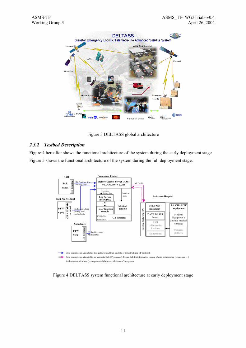
2.3.1 Overview Figure 3 gives an overview of the system in its full deployment phase. The system is organised in relative independent subsystems. Most of these subsystems have been defined with existing or adapted elements. However some software have been developed mostly for the interfaces between some elements of the system
ASMS-TF ASMS_TF- WG3Trials-v0.4Working Group 3 April 26, 2004
11
Figure 3 DELTASS global architecture
2.3.2 Testbed Description Figure 4 hereafter shows the functional architecture of the system during the early deployment stage
Figure 5 shows the functional architecture of the system during the full deployment stage.
First Aid Medical
Ambulance
Reference Hospital
SAR
Equip.
PTWEquip.
PTWEquip
SAR
GB
term
inal
GB
+ IN
M/M
4te
rmin
al
GB
term
inal
Data transmission via satellite to a gateway and then satellite or terrestrial link (IP protocol)
Data transmission via satellite or terrestrial link (IP protocol). Return link for information in case of data not recorded (erroneous, …)
Audio communications (not represented) between all actors of the system
ID, Position, time,Priority level All DATA
ID, Position, time,Priority level,medical data
ID, Position, time,Medical Data
DELTASSequipment
LA CHARITEequipment
DATA BASESServer
Ku terminal
Inte
rnal
Net
wor
k (I
P)
ASPI collaborative
Platform
Medical Equipment’s
(include medical console)
Winvicosplatform
Co-ordinationconsole
Remote Access Server (RAS) + LOCAL DATA BASES
Permanent Centre
Medicalconsole
Log dataHistory data Medical
data
INM/M4terminal
Log ServerDATABASE
GB terminal
Figure 4 DELTASS system functional architecture at early deployment stage

ASMS-TF ASMS_TF- WG3Trials-v0.4Working Group 3 April 26, 2004
12
Other Hospitals
Mobile Field Hospital
Internal Network (IP)
Medicalconsole M
edic
al
equi
pmen
t’s
Ku
term
inal
Vis
io c
onfe
renc
e Eq
uipm
ent's
, C
olla
bora
tive
Plat
form
, W
invi
cos,
…
Ambulance
Reference Hospital
Co-ordinationconsole
Remote Access server (RAS)
+ LOCAL DATABASES
SAR
Equip.
PWTEquip.
PWTEquip
Permanent Centre
DELTASSequipment
LA CHARITEequipment
DATA BASESServer
Ku terminal
Medical Equipment’s
(include medical console)
WinvicosPlatform
Inte
rnal
Net
wor
k (I
P)
SAR
GB
term
inal
GB
+ IN
M/M
4te
rmin
alG
B te
rmin
al
DA
TA B
ASE
SSe
rver
First Aid Medical
GB terminal
Data transmission via satellite to a gateway and then satellite or terrestrial link (IP protocol)Log data transmission via satellite (Inmarsat or Globalstar)Data transmission via satellite or terrestrial link (IP protocol). Return link for information in case of data not recorded (erroneous, …)Satellite High Rate transmissionTerrestrial link (only for additional videoconferencing services)Audio communications (not represented) between all actors of the system
All DATA
. Mirroring of patient database
. Videoconferencing
ASPICollaborative
Platform
INM/M4 terminal
ID, Position, time,Priority level,medical data
ID, Position, time,Priority levelMedical Data
ID, Position, time,Priority level
DATA
Log Server+ Log DATABASE
Log dataHistory data
INM/M4terminal
Figure 5 DELTASS system functional architecture at full deployment stage
The different parts of the system are:
• The mobiles teams which will be deployed on disaster site for search, identification, first triage and evacuation of victims:
• They are composed of SAR (Search And Rescue) teams equipped with portable telephone and PDA, First aid Medical teams with PTW (Portable Telemedicine Workstation) and Ambulance teams with PTW.
• They will communicate with the Co-ordination and medical teams located in Permanent Centre or Mobile Field Hospital via low rate or medium rate satellite telecommunication systems
• A Permanent Centre which could be located in the foreign country bringing the humanitary help. It will receive all data from the mobile teams, manage them and redirect all data to a Reference hospital and adequate data to the Mobile Field hospital. The Permanent Centre will assure the co-ordination and medical functions while the Mobile Field is under deployment
• A Mobile Field Hospital (MFH) which will be deployed at disaster site to provide all activities related to the co-ordination of the mobile teams on disaster site, the victims medical triage, reception, first aid treatment, conditioning for transportation, further medical expertise of some patients by use of the access to external medical databases or of videoconferences between MFH and Reference Hospital. The management of all patient data are also performed for patients still under MFH control.
• A Reference Hospital in regional or foreign country, which will act mainly as an expert background for the MFH for further medical expertise and triage.
• In that frame, the high rate communication link which will be installed between MFH and the Reference hospital will allow to perform videoconferencing and Telemedical services, as on-line and off-line Telediagnosis in order to get more expertise and real time advice from remote medical specialists. Advanced Telemedical services using this link will also be performed, as interactive live teleconsultation, interactive telepathology, interactive intraoperative simulation.

ASMS-TF ASMS_TF- WG3Trials-v0.4Working Group 3 April 26, 2004
13
During DELTASS demonstrations, the high rate communications between the Mobile Field Hospital and the Reference Hospital are performed using of EUTELSAT system.
The choice of the low rate and medium rate telecommunications between the mobile teams and the Permanent Centre or the Mobile Field Hospital has been done through a trade-off study between the following systems: IRIDIUM, EMSAT, GLOBALSTAR, and THURAYA.
The three last systems have been tested by CNES on a practical point of view, with customers oriented utilisation. A short preliminary qualitative information about these tests is:
GLOBALSTAR has good performances (data), the offered services are of good standard and the link is robust, even in cities (few interruptions). Hand-held equipment is rather handy, and accessories exist for use in a car.
THURAYA is much more sensitive to propagation conditions (voice). Trees and buildings may block the signal much easier than for GLOBALSTAR. The receiver has to be in satellite view This is a known drawback of a single geosynchronous satellite when compared to a constellation. The GPS receiver is a good feature, as the position can be sent directly as SMS. The handset is very compact and handy, but at present no accessory were available for use in a car.
EMSAT has rather poor quality performances (voice), and the terminal cannot be used as a handset one: its setting is rather tedious and it needs at least a car to provide housing and power. This is considered as a destructive characteristic.
Conclusions of the trade off study:
• For the reference scenario and with respect to the applicable and reference documents, the solutions which have been selected were:
• GLOBALSTAR for the voice and low rate data from the mobile teams, extended to medical data in ambulances,
• INMARSAT for the medical data from the medical suitcase on the disaster site.
2.3.3 Demonstration and Trials Two life size demonstrations have been performed in the hypothesis of the reference scenario (disaster situation):
• SITEF demonstration
This demonstration focused on the activities performed during the early phase of the system deployment. It did not involved the MFH and the Reference Hospital
• ULM demonstration
This demonstration involved the complete system. However, the demonstration started when the MFH was fully installed and operational
2.3.3.1 SITEF demonstration This demonstration of the DELTASS system reduced to the mobility segment has been organised in the frame of the SITEF exhibit on 24th of October in Toulouse (France).
The DELTASS subsystems involved in this demonstration were:
• The mobile operators subsystems
• The permanent Centre
• Remote site for co-ordination and medical consoles
The disaster site was located on the “Pech David” hill at Toulouse. It included, besides simulated victims and SAR teams, a medical check point with a FMA. An ambulance was also used to simulate victims’ transportation to the Rangueil Hospital.

ASMS-TF ASMS_TF- WG3Trials-v0.4Working Group 3 April 26, 2004
14
The coordination console and medical console were located in the SITEF exhibit itself (Parc des Expositions at Toulouse.
SDIS (Fire Brigade of Toulouse) and SAMU 31 (Healthcare Emergency department of Toulouse Hospital) with their materials have contributed to play the role of the actors (victims, rescue teams, paramedical teams, doctors, …) during the demonstration.
Satellite links configuration
• voice and data between SAR teams and Coordination Centre: Globalstar
• ambulance - Coordination Centre link: Globalstar
• FMA - Coordination Centre link: Inmarsat M4
2.3.3.2 ULM demonstration It concerned the full demonstration of DELTASS system with a Mobile Field Hospital installed at Rommelkaserne in ULM for the demonstration purpose.
The deployment of the MFH, which has not been performed in real time was shown on a video film already recorded.
The German military paramedical and medical staff has actively participate to this demonstration as actors during the demonstrations and for its organisation (materials, choice of the site for mobile teams, guests reception, …).
About 50 external people, in particular from civil and military medical world have been invited and 30 of them attended the demonstration.
Configuration
The different elements of DELTASS system were located at the following sites :
• Mobile teams (SAR, FMA, Ambulance) deployed near to the MFH deployment at 89160 ULM-Dornstadt, auf dem Lerchenfeld 1 (Germany)
• MFH (Mobile Field Hospital) was installed at the Base of the German KRK-Base 89160 ULM-Dornstadt, auf dem Lerchenfeld 1.
• Permanent Centre located at MEDES premises at Toulouse (France)
• Reference Hospital was played by Charite Hospital at Berlin (Germany)
The Berlin site (RH) covered various departments of the Robert-Roessle-Klinik: conference room with surgeons, radiology room with radiologist, and demonstration room with histologist.
According to the DELTASS definition,, the Permanent Centre was limited to the data acquisition from the Globalstar and Inmarsat gateways and transmission of all data to the data base server at the RH and transmission of the Log data and position data to the Log Server (in Permanent Centre) which push them to the coordination console at the MFH.
Demonstration
A as run leading procedure was used for this demonstration.
The satcom subsystem stayed in the same configuration. A last minute problem brought some fears in the teams when suddenly the Eutelsat service stopped one hour before the demonstration. Fortunately, the service resumed just in time. The subsystem behaved well and especially it was demonstrated that service with high data rate could well use the same data channel as service with a much lower data rate.
The mobility segment went on schedule without noticeable problem - the rainy weather excepted.
The data transfer worked in the same configuration as during the rehearsal. An additional hardware failure occurred during the demonstration, but not obvious for the attendance: the interface server

ASMS-TF ASMS_TF- WG3Trials-v0.4Working Group 3 April 26, 2004
15
stayed stuck in the Permanent Centre in Toulouse for a short while. This caused some delay for the files collected during that period, but none was lost.
Level 1 telemedical services: It was possible to use some of the collected medical files to perform interactive diagnosis with Berlin, both on-line and off-line, and to transmit pictures. Activities during the triage period (written notes, data base access) were also demonstrated and got a good attendance attention.
Level 2 telemedical services: the “victims” were employed to play some pre-defined scenarios with the hospital in Berlin by use of the facilities installed in the MFH and the high rate data transfer. This was very spectacular and appreciated by the attendees.
Guests visited the activities on the field, despite the rain, and then in the MFH. Their interest was obvious and lot of questions were asked.
After one hour of performance, it turned out that the attendance has seen enough from the on the field (or real time) activity and was more interested in level 1 and level 2 services and in questions to the various subsystems. It was therefore decided to abort the demonstration at that point, the more than the weather was still rainy, so rather uncomfortable for the actors on the field.
2.3.4 Results
2.3.4.1 Sitef demonstration All foreseen situations were successfully tested. Data transfer, localisation and data visualisation were excellent all along the demonstration.
Cooperation with Firemen for SAR team and ambulance was a very fruitful idea, as it was possible to check that “professionals” of the SAR activity were immediately captivated by the use of this technique and became operational very rapidly.
The participation of the healthcare emergency teams allows to appreciate their interest for using such systems in usual emergency situations.
Many local media were present and the promotion of DELTASS system was well assured through this media and through the articles written on the web. A video film was built about this demonstration.
2.3.4.2 Ulm demonstration Despite some recorded problems the demonstrations can be considered as a success by themselves and also prove the success of the DELTASS program:
• Necessary communication in emergency situation can be established at both low rate (voice and data) from the disaster field and high rate (data) from a Field Hospital with very few adaptation to existing systems;
• Telemedical functions exist and can use such communication lines to largely improve the medical situation in case of disaster;
• Overall coordination can be performed from a remote site with limited means
2.3.4.3 Conclusion The definition, integration and demonstration of an experimental space based telemedicine system have been successfully performed thanks to DELTASS project and ESA founding.
Thus, the DELTASS project has defined the basic elements of a complete telemedicine system to be deployed in case of disaster situation.
It is to be noted that the size of the system could be adapted to the importance of each situation by extension of the number of elements and of the rental of the satellite channels.
Some part of the system could be used without any modifications for other applications. For example the mobility segment could be used for mountain coordination and medical needs or for traveller
ASMS-TF ASMS_TF- WG3Trials-v0.4Working Group 3 April 26, 2004
16
medical needs. The telemedical services could be used for the expert medical needs in isolated area or between 2 hospitals sharing medical teams and equipment.
The DELTASS demonstrations have clearly highlighted the interests and the effectiveness of the proposed satellite based telemedicine system for medical emergency needs in disaster situation.
The suitability of the proposed equipment and software such as SAR terminal, PTW, patient data bases, etc, have been shown through the positive reactions of the actors involved in their utilisation and of the guest people.
Actually, the participation of the paramedical and medical people involved usually in emergency medicine allowed to verify the easiness to use the light space-backed equipment defined for the mobile teams with a minimum time of training.
The suitability of the satcom system for interactive telemedical videoconference needs have been establish through the interactive live telemedicine services performed in parallel with other activities such as data transmission or database replication. However, the bandwidth to reserve in real situations is to be evaluated according the dimension of the catastrophe (gravity, number of potential victims, …)

ASMS-TF ASMS_TF- WG3Trials-v0.4Working Group 3 April 26, 2004
17
2.4 THE FIFTH PROJECT FIFTH (Fast Internet for Fast Train Host) is an EC Project (IST-2001-39097). It started in September2002 and its duration is 16 months. Project participants are Alenia, Italy, Inmarsat UK, Trenitaila, Italy, DLR, Germany, Bradford University, UK and Radiolabs, Italy. For further information see http://www.fifth.it.
2.4.1 Overview The goal of the FIFTH project is to define and validate a multi-segment (satellite/wireless-LAN) communication infrastructure for the provision of mobile, QoS-sensitive, Internet services to the passengers of high-speed trains. Towards this end, the FIFTH project specialises all the outcomes of the SUITED project to the railway scenario.
The FIFTH target system will consist of a multi-segment access network connected to the Internet network. The multi-segment access network will adopt a broadband Ka-band satellite network as primary communication medium and a wireless-LAN (W-LAN) as back-up system able to bridge the satellite connectivity in all those environments (e.g. tunnels or near-building urban areas) where the satellite coverage is not available. The FIFTH Internet network is a portion of the legacy Internet which implements Mobile IPv6 protocols along with some specific functionality for the support of the Quality of Service (QoS). By means of the FIFTH system, Internet (IP and MPEG over IP) and digital TV services will be provided to a population of nomadic users, or tele-commuters, who will travel by high-speed trains.
2.4.2 Testbed Description The FIFTH demonstrator test-bed will basically consist of:
1. A mobile multi-mode terminal mounted on board high-speed trains. This prototype will be composed of a satellite and a W-LAN terminal interconnected to a Terminal Inter-Working Unit (T-IWU) hosting the functionality in charge of mobility management and QoS support, a navigation unit and a LAN internal to the coaches, which provides connectivity to the passengers.
2. A network infrastructure composed of a wireless multi-segment access portion based on satellite and W-LAN systems, and an Internet portion, implementing specific functionality necessary for the deployment of the mobility and QoS support solutions designed in the framework of the Project. Interconnection to the legacy Internet is also envisaged.
2.4.3 Demonstration and Trials In particular this activity aims at defining a validation strategy, at specifying, designing, developing and testing a prototypal version of the high-speed train terminal, at designing and developing a demonstrator network infrastructure, at designing and developing a radio channel measurements system and, finally, at executing the trial campaign and evaluating the results collected.
Urban Area Tunnel AreaOpen Area
Figure 6 FIFTH trials environment
2.4.4 Results TBC

ASMS-TF ASMS_TF- WG3Trials-v0.4Working Group 3 April 26, 2004
18
2.5 THE FUTURE PROJECT
2.5.1 Overview The FUTURE project aims at adopting recent advances in the Internet arena in UMTS by exploring the applicability of native Internet protocols (in accordance with IETF multimedia data and control architecture) in 3G. Special emphasis is given to core network consolidation towards a general purpose multi service UMTS connectivity network, legacy GSM/UMTS voice service migration to the consolidated packet based UMTS core network domain, and the introduction of a wide range of optimised multimedia communication and information services, based on SIP and Web techniques. The integration of telephony services with information services is regarded as base for end-user service multiplication and will be combined with inherent capabilities of S-UMTS satellites like wide area coverage, broadcasting, and location determination. Key functions of the envisaged full service IP based target UMTS will be identified, designed, and demonstrated, using the VIRTUOUS Demonstrator, funded under the first call of the 5th FP, as a starting point. FUTURE adds value to the European Commission funded VIRTUOUS project in several respects, being centred around the integration of a Session Initiation Protocol (SIP) based multimedia domain into the network operator’s/ service provider’s infrastructure and the design of a satellite radio resource management framework, including efficient packet-based access for the forward-link of the satellite.
Figure 7 FUTURE Reference Architecture
The figure above depicts the FUTURE reference architecture, where a mobile station is attached to the UMTS core network through three different access networks: a satellite access network (USRAN) based on the SW-CDMA radio technology by ESA; an UTRAN access based on Release 99; and a GPRS access. The three access networks are considered to be run by the same UMTS operator, and to share the same core network. The overall technical objectives of FUTURE are: the design and demonstration of an IP Multimedia Subsystem (IMS) deployed in the common core network of the reference model, and the design and demonstration of QoS guaranteeing functions framed in the context of a Radio Resource Management (RRM) system for the satellite access network (USRAN). The IP Multimedia Subsystem will serve users accessing the core network through USRAN, UTRAN, GPRS or a combination of them by means of a multimode terminal. The IMS will be made aware of the segment(s) a certain user is actually attached to, enabling service provisioning adapted to and exploiting the advantages of the available access networks.
2.5.2 IP Multimedia Services Provisioning The emerging need for providing a wide variety of enhanced multimedia services to the subscribers of PLMN networks has imposed great requirements to the existing cellular infrastructures. Most

ASMS-TF ASMS_TF- WG3Trials-v0.4Working Group 3 April 26, 2004
19
importantly, the convergence of the cellular and the Internet world necessitates that those services are based on and built upon the current Internet applications, services and protocols. To this end, 3GPP has introduced the so-called IP Multimedia Subsystem (IMS) by complementing the existing circuit and packet-switched domains and enabling in this way the provision of such QoS-demanding real-time services. This subsystem exhibits really promising capabilities to meeting those challenges whereas it uses the Session Initiation Protocol (SIP) protocol as the main mean for addressing the signalling requirements within the IMS The FUTURE project, while trying to stay in line with the 3GPP specifications for the IP Multimedia Subsystem, has applied the 3GPP architecture on the one hand and has defined an IP Multimedia Subsystem tailored to a combined satellite and terrestrial environment on the other hand. However, some simplifications have been made concerning the ensemble of the network entities and the functionalities being implemented by each component. Thus, a minimum set of multimedia components for the Multimedia Subsystem has been identified and, as a consequence, the IMS architecture depicted in Figure 8 has been deduced. As illustrated, the IMS consists of the Call and Session Control Function (CSCF), the Home Subscriber Server (HSS), the Feature Server (FS) and three additional servers –web, media and MC/BC servers– for the support of the multimedia services. The CSCF assumes the role of all the three different CSCFs that reside in the 3GPP IMS with some further simplifications applied on it. This approach has been chosen in order to avoid the implementation of any redundant functionality by covering all the different CSCF roles, which is not considered essential for the FUTURE demonstrator system. The simplifications performed at the CSCF functionality derive mainly from the fact that only one CSCF exists and therefore there is no need for procedures such as CSCF selection or subscriber Location queries for terminating calls.
Figure 8 FUTURE IMS architecture
Concerning the HSS, as it can be seen from the figure above, it is comprised of two functional blocks, the Home Location Register (HLR) which is used by both the CS and the PS domain and the User Mobility Server (UMS), which maintains the information relevant to the IMS. However, in the context of the FUTURE project and for the needs of the IMS, only the UMS part is implemented and no interface exists with the HLR. Therefore, the user information stored in the UMS (registration status, user identities. IP address, subscribed services, service options etc.) will suffice for the procedures carried out within the multimedia subsystem. The Feature Server is of prime importance within the Multimedia Subsystem since it is assigned with the execution of the services. In general, the Feature Server should provide means for enabling the network operator to perform an easy service creation. For the implementation of the different end-user services that have been identified for the FUTURE IP Multimedia Subsystem demonstrator, the Feature Server has been specified in the form of an Application Server (AS) which realises the service logic and communicates with CSCS through SIP. In the context of FUTURE, an universal approach for a Feature Server has been chosen, which incorporates functionality for a common Feature Logic, as is is the one necessary for the handling of SIP signalling messages, as well as more complex functionality for the support of specific applications (presence, location etc), as it will be described later.
ASMS-TF ASMS_TF- WG3Trials-v0.4Working Group 3 April 26, 2004
20
The S-CSCF and the Feature Server end-points in FUTURE are functionally viewed as SIP servers. From the S-CSCF point of view the Feature Server may behave like a SIP proxy/redirect server (i.e. it may either proxy incoming SIP requests or it may redirect them) or like a SIP User Agent or as 3rd party session controller. The S-CSCF acts like a SIP proxy/redirect server with respect to an internal logic or based on the results of applying some filter criteria to the SIP messages. It also serves as SIP REGISTRAR server, and maintains all the UE information of users, which have registered with it. The S-CSCF proxies the request to the next hop server which may be a SIP proxy again, a Feature Server or a User Agent Server.
2.5.2.1 Multicast/Broadcast provision By identifying the great advantages of the satellite systems in terms of the satellite coverage capabilities, multicast and broadcast issues are investigated and implemented in FUTURE, having in mind that this type of services is expected to pose an extraordinary argument in favour of the consideration of satellites for the next generation networks. In this respect, the aim of FUTURE is to establish the means for a network-efficient and appealing-to-users provision of Multicast /Broadcast services through the IP Multimedia Subsystem and exploiting both, the terrestrial and satellite access components. Note that IMS is a natural candidate to provide BC/MC, since SIP and SDP were originally designed for the support of large-scale multicast conferences and different conferencing models have been proposed with SIP. The work undertaken by FUTURE is based on the analysis of technical specifications and drafts from standardisation bodies 3GPP and IETF. In particular, it basically considers the Multimedia Broadcast / Multicast Service (MBMS), which is currently being standardised by 3GPP for UMTS Release 6. The outcome consists of a system and network architecture able to support BC/MC services in a T-S-UMTS network, and the design of procedures enabling the provision of such a services through the IP Multimedia Subsystem.
2.5.2.2 Service trials One of the objectives of the FUTURE project is the implementation of applications, which combine the advantages of both real-time multimedia communication services and non real-time Web based information services as well as the inherent capabilities of the satellite communications and the benefits of heterogeneous radio environments. As such, six services have been implemented with the aim of fulfilling the aforementioned requirements and of evaluating the effectiveness of the FUTURE IMS with regard to the demanding nature of such services. • The 3rd Party Call Control service enables a served user to establish an audio conversation with another user. The establishment of a call according to this service is controlled by a 3rd party, i.e. the Feature Server is responsible for the establishment of both call legs towards the calling and the called user. • The User Initiated Session Modification service enables a served user to establish an audio conversation with another user. Whereas in this case, it is possible for the served user to either change the session characteristics (media type) or to establish an additional session to the already existing one. • The Location Based service enables a served user to receive information, which is dependent on his/her actual geographical location. In particular, the whereabouts of the user are communicated to the Feature Server via a Location Server. At this point, the former is able to notify the subscriber of location-based information whose format consists of plain text. • The Context Awareness of Application service enables a served user to receive information, whose Quality of Service demands depend on the actual access segment over which the served user is connected. The available access segments vary among the GPRS segment, the satellite based UMTS and the terrestrial UMTS segment, each providing a different bit rate. Therefore, “black & white” video streams, “coloured” video streams with low, medium and high quality could be supported dependent on this information.
• The Presence service enables a served user to receive information that reveals the actual state of other users. This information service requires prior subscription of the served user and his/her authorization for enabling the other users to receive this kind of information. The presence status of a

ASMS-TF ASMS_TF- WG3Trials-v0.4Working Group 3 April 26, 2004
21
user may consist of his/her communication status (e.g. online, available, busy) or his/her communication means (e.g. email, call, instant messaging). This service employs a new QUATH SIP message for ensuring that authorisation has been granted to certain users.
• The Tele-learning service, provides means for the communication between a teacher and several students. In order to efficiently use radio resources the communication path from the teacher to the students is performed via multicast operation via the S-UMTS segment. Separate individual connections from each of the students back to the teacher are employed, which utilize the T-UMTS segment.
2.5.3 QoS in UMTS Satellite Radio Access Network (USRAN) Several TDMA and CDMA radio access technologies have been proposed for the satellite component of IMT2000. In FUTURE, a CDMA environment is assumed in USRAN, looking at attaining maximum synergy with the terrestrial segment, based on the W-CDMA technology.
Modules such as packets schedulers, admission controllers, power controllers or congestion controllers are involved in the management of radio resources. In the following we briefly describe the key FUTURE modules related to QoS, showing then how these modules are combined and linked so as to make up a RRM framework providing QoS enabled Radio Bearers.
A. Call Admission Control An Admission Control Strategy has been investigated in FUTURE aimed to evaluate the capacity of the radio interface to support new connections, taking into account the newly requested resources (derived from QoS parameters), the resources consumed by current connections and the maximum capacity of the radio interface. The target pursed by the admission controller can be faced by applying different schemes adapted to capabilities of the system. A couple of examples in WCDMA are the power-based and throughput-based algorithms. On the other hand, the FUTURE approach is an interactive SIR-based algorithm that aims at finding out whether a power equilibrium point can be reached respecting satellite and terminal power budgets, so that all target SIRs are met after accepting the call. Given that the acquisition of instantaneous measurements on power levels, interference levels or propagation conditions may lead to erroneous CAC decisions due to the varying nature of the WCDMA radio interface and of the packet services, instantaneous measurements are properly processed over time windows to regard the time variations of the measured values.
Besides power and interference effects caused by the new connection, the FUTURE CAC also checks that capacity of the network to support the required bandwidth and delay by means of a capacity planning function provided by the DSCH Scheduler. A mid-term simulation of the averaged traffic presently cursed is performed in order to estimate the resources left for the new connection.
B. Scheduling The main purpose of the Scheduling management function is to optimise the radio resources utilisation, and in particular maximising the amount of accepted requests and the data flow throughput, as well as satisfying given QoS parameters. In order to respect the Radio Access QoS sub-contract, the MAC scheduling function assigns W-CDMA codes and radio frames to data packets so that contracted QoS specifications (involving such indicators as delay or jitter) are met. Among the possible CDMA techniques, FUTURE adopts an OVSF scheme in which codes are organized into a code tree, and each user is assigned a single orthogonal code in the tree. We consider the scenario of the FUTURE demonstrator, in which different services and/or applications can simultaneously be provided to two mobile users by a unique physical channel (Downlink Shared Channel, DSCH) per satellite beam. In this context, the scheduling function has to solve the following problem: (i) selecting a transport format (TF) so as to maximise the data flow sent in the current transmission time interval (TTI).

ASMS-TF ASMS_TF- WG3Trials-v0.4Working Group 3 April 26, 2004
22
(ii) allocating the available band of the shared channel (DSCH) in downlink to MTs so as to guarantee to both MTs the timely delivery of a sufficient data flow in a mid-term time horizon.
The functionality developed to cope with the latter item represents the most innovative aspect of the Scheduler, and is implemented by a module (capacity planner) in charge of allocating the band so as to guarantee the required QoS to both MTs in the mid range.
C. Active Set Handling The Active Set Handling for S-UMTS is based on the satellite diversity concept, which can provide benefits in terms of reduced blockage probability, soft and softer-handoff capability, slow fading counteraction, and under certain conditions even increased system capacity. The Active Set Handling allows diversity in the forward link, permitting exploitation of antenna arrays and rake receiver at the MT side. It operates in S-UMTS as a countermeasure to blockage-induced outage due to the on/off propagation channel properties. The concept of the active set is strictly related to the soft-handover one: soft-handover is a handover in which the UE starts communication with new satellite beam, on the same carrier, frequency, or sector of the same site (softer handover), performing utmost a change of code. Based on the measurement of the set of cells monitored, the soft-handover function evaluates if any satellite beam should be added to (radio link addition), removes from (radio link removal), or replaced in (combined radio link addition and removal) the active set of links. The difference between the proposed S-UMTS active set handling algorithm and the T-UMTS one lies in the time scale considered for incoming measures and/or in threshold introduced for different monitored beams. On the other hand, the actions taken into account by these algorithms are the same. The size adopted for the Active Set may vary, but usually it ranges from 1 to 3 beams. The upper value is conceived in order to avoid not only RF interferences and CDMA code depletion, but also to exploit low power level consumptions.
D. Physical Layer issues As mentioned above, the satellite radio technology assumed by FUTURE is the SW-CDMA proposed by ESA for the satellite component of IMT2000. Some enhancements to this standard are proposed by FUTURE, specifically on the Physical Downlink Shared Channel (PDSCH). In this respect, broadcast OVSF codes to transport efficiently MC/BC traffic at the radio interface, optimum signalling scheme and Open Loop power control have been investigated. Concerning the satellite constellation, both LEO and GEO configurations are considered in FUTURE. In either case a transparent payload is assumed
2.5.3.1 FUTURE RRM All of the QoS modules described above, along with other required modules not directly related to QoS assurance, are put together and coordinated building up a so called Radio Resource Management (RRM) framework, responsible for the provision of the radio QoS as a whole. Figure 9 reflects the overall RRM architecture in FUTURE.
Simultaneously to QoS guaranteeing, it is desirable from the network operator perspective to achieve maximum system capacity on the radio interface. The QoS assurance and the maximisation of the system capacity are assessed in the QoS trials run in the project, aiming at harmonising these two aspects in the most optimised way.

ASMS-TF ASMS_TF- WG3Trials-v0.4Working Group 3 April 26, 2004
23
Figure 9 FUTURE RRM architecture
2.5.4 Demonstration and Trials The S-UMTS QoS and IP Multimedia Subsystems designed in FUTURE are implemented building up the FUTURE demonstrator, which will allow the validation of the solutions and concepts developed in the project. A realistic satellite scenario is achieved in the testbed by means of the so called Physical Layer Simulator Element (PLSE), a real time hardware simulator featuring the SW-CDMA radio channel as well as the physical layers of the mobile terminal and the gateway. The satellite PLSE emulates two satellites, two fully functional MTs and a multitude of additional terminals simulated in terms of intra beam and inter beam interference. Another PLSE emulating the UTRAN physical layer (with just one physically emulated MT and the second one only virtually emulated) and real GPRS equipment complete the physical layers of the three access networks foreseen in the FUTURE reference model.
Figure 10 FUTURE Demonstrator Architecture Figure 11 Radio scenario in the FUTURE Demonstrator
The radio scenario created by the satellite and terrestrial PLSEs (S-PLSE and T-PLSE respectively) is represented in Figure 11. The whole FUTURE demonstrator, depicted in Figure 10, is divided in two main blocks: the bearer level and the application level. The bearer level is composed, in turn, of a satellite bearer system and a terrestrial bearer system.
ASMS-TF ASMS_TF- WG3Trials-v0.4Working Group 3 April 26, 2004
24
The satellite bearer system includes the satellite PLSE, USRAN QoS modules and diverse functionality – SM, RLC, RRC and MAC functions– required to provide satellite PDP contexts with QoS guarantees. To note that the term bearer makes reference to the UMTS bearer, since the functions implemented ranges from the MT up to the GGSN in the core network. Some details of the satellite bearer system are:
• Transport channels: – FACH (3.8 Kbits) and DSCH (64 or 128 Kbits) on the downlink. – DCH (128 Kbits) on the uplink.
• 4 QoS classes; 4 QoS parameters: Error rate, Delay, Bit Rate and Priority. • 14 bi-directional, QoS enabled, logical channels per user; dynamically established, modified
and released. • 1 downlink multicast logical channel carried over DSCH.
The terrestrial bearer system, which enables terrestrial PDP contexts for the IMS applications. Contrary to the satellite case, the terrestrial PDP contexts are pre-configured and so are not subject to admission control nor to session management. The terrestrial PLSE provides a bi-directional DCH channel (128 Kbits) per user. The application level contains the components of the FUTURE IP Multimedia Subsystem at user and network sides. All of the traffic generated at the application level by the IMS applications is routed to the bearer level (either to the satellite bearer or to the terrestrial bearer) so as to communicate the user and network sides. Besides, concerning the control plane, applications are able to select the QoS with which their flows are carried within the bearer level. An interface to the session management (SM) modules located on MTs is provided to the IMS so that the multimedia services can ask for the establishment/modification/release of PDP contexts with a QoS in accordance to the session characteristics previously negotiated with SIP signalling.
2.5.5 Results The IST FUTURE project has contributed to the demonstration and validation of key concepts in S-T-UMTS. The main impact provided by project can be summarised as follows:
• Definition and implementation of a SIP-based IP Multimedia System (IMS) for general service provisioning in UMTS networks with multiple-AN (UTRAN, USRAN, GPRS) and a shared CN; validated through a set of innovative applications exploiting the network possibilities.
• Definition and implementation of a Radio Resource Management System for SW-CDMA, including efficient packet-based access and validated with a hardware-based test-bed, that guarantees QoS for end users and efficiency of resources usage for network operators.
• Definition of a preliminary deployment of MBMS services in a hybrid Terrestrial-Satellite UMTS scenario, including implications on the access network for the efficient transport of multicast traffic and validated by means of a multicast application provisioned through the defined IMS.
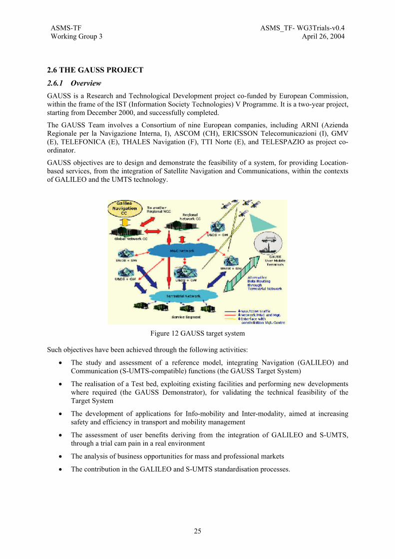
ASMS-TF ASMS_TF- WG3Trials-v0.4Working Group 3 April 26, 2004
25
2.6 THE GAUSS PROJECT
2.6.1 Overview GAUSS is a Research and Technological Development project co-funded by European Commission, within the frame of the IST (Information Society Technologies) V Programme. It is a two-year project, starting from December 2000, and successfully completed.
The GAUSS Team involves a Consortium of nine European companies, including ARNI (Azienda Regionale per la Navigazione Interna, I), ASCOM (CH), ERICSSON Telecomunicazioni (I), GMV (E), TELEFONICA (E), THALES Navigation (F), TTI Norte (E), and TELESPAZIO as project co-ordinator.
GAUSS objectives are to design and demonstrate the feasibility of a system, for providing Location-based services, from the integration of Satellite Navigation and Communications, within the contexts of GALILEO and the UMTS technology.
Figure 12 GAUSS target system
Such objectives have been achieved through the following activities:
• The study and assessment of a reference model, integrating Navigation (GALILEO) and Communication (S-UMTS-compatible) functions (the GAUSS Target System)
• The realisation of a Test bed, exploiting existing facilities and performing new developments where required (the GAUSS Demonstrator), for validating the technical feasibility of the Target System
• The development of applications for Info-mobility and Inter-modality, aimed at increasing safety and efficiency in transport and mobility management
• The assessment of user benefits deriving from the integration of GALILEO and S-UMTS, through a trial cam pain in a real environment
• The analysis of business opportunities for mass and professional markets
• The contribution in the GALILEO and S-UMTS standardisation processes.
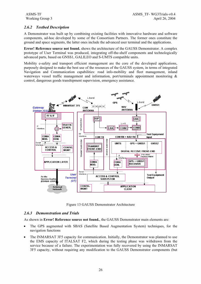
ASMS-TF ASMS_TF- WG3Trials-v0.4Working Group 3 April 26, 2004
26
2.6.2 Testbed Description A Demonstrator was built up by combining existing facilities with innovative hardware and software components, ad-hoc developed by some of the Consortium Partners. The former ones constitute the ground and space segments, the latter ones include the advanced user terminal and the applications.
Error! Reference source not found. shows the architecture of the GAUSS Demonstrator. A complex prototype of User Terminal was produced, integrating off-the-shelf components and technologically advanced parts, based on GNSS1, GALILEO and S-UMTS compatible units.
Mobility e-safety and transport efficient management are the core of the developed applications, purposely designed to make the best use of the resources of the GAUSS system, in terms of integrated Navigation and Communication capabilities: road info-mobility and fleet management, inland waterways vessel traffic management and information, port/terminals appointment monitoring & control, dangerous goods transhipment supervision, emergency assistance.
Figure 13 GAUSS Demonstrator Architecture
2.6.3 Demonstration and Trials As shown in Error! Reference source not found., the GAUSS Demonstrator main elements are:
• The GPS augmented with SBAS (Satellite Based Augmentation System) techniques, for the navigation functions
• The INMARSAT 3F5 capacity for communication. Initially, the Demonstrator was planned to use the EMS capacity of ITALSAT F2, which during the testing phase was withdrawn from the service because of a failure. The experimentation was fully recovered by using the INMARSAT 3F5 capacity, without requiring any modification to the GAUSS Demonstrator components (but

ASMS-TF ASMS_TF- WG3Trials-v0.4Working Group 3 April 26, 2004
27
adjustment of the frequency plan in transmission and reception, according to the authorisation of the IMARSAT Spectrum Manager)The advanced multi-mode User Terminal, composed by:
o A unique integrated digital receive front-end capable of handling the full navigation (GPS, EGNOS, GALILEO) and communication (S-UMTS) band segments signals,
o The GNSS1 (GPS + EGNOS) receiver, designed for precise positioning and navigation operations within a Satellite Based Augmentation Service environment
o The SW-CDMA modems and the UMTS compatible access system, specifically tailored to location based services (low-rate, small packet transmission standard)
o The applications, based on use of GIS (Geographic Information System) technology, standards and open-source components.
A trial campaign, run into real environments, was performed in Summer 2002. GAUSS Demonstrator performances and benefits were validated with the direct involvement of an inter-modal transport user (ARNI, Partner of the GAUSS Consortium), specifically operating in inland-waterways and roads. Safety-of-life applications for assisted vessel navigation and for management of hazardous goods (gas) transhipment over the Po river were thoroughly tested and assessed. Applications for emergency assistance, Point of Interest inquiry, localisation of commercial fleet were also proven.
Figure 14 The GAUSS Demonstration Campaign
GAUSS successfully demonstrated integrated Satellite Navigation GNSS1 precise positioning based on EGNOS, and satellite UMTS packet communication, for provisioning of high quality location based services. The new technology with respect to the current state-of the art, developed within the project, was validated during the trial campaign, including the implemented broadcasting and multicasting communication of data packet compliant to 3GPP standard (current release 4). In this framework GAUSS had fruitfully contributed to the ETSI SES S-UMTS Working Group activities and results.

ASMS-TF ASMS_TF- WG3Trials-v0.4Working Group 3 April 26, 2004
28
Figure 15 GAUSS Demonstrator Application Elements
Horizontal accuracy better than 3-m was achieved in the trial area (Northern Italy - Lario, Como Lake, Parma and Po river areas). The MTB (Mediterranean Test Bed) was utilised because of the poor performance coverage of the ESTB system over the Italian regions.
2.6.4 Results GAUSS results open the way to the development and exploitation of advanced technology supporting high quality, reliable and effective services to the citizens for the transport sector and whole mobility domain, in view of GALILEO and UMTS scenarios: emergency assistance, safety-of-life applications, fleet and freight transport management (rail, road, maritime and inland waterway), dangerous goods transportation and containers tracking.
Project main results:
• Realisation of an integrated COM and NAV Mobile User Terminal, for S-UMTS communication and GPS, EGNOS and GALILEO navigation
• Implementation of a UMTS low-rate packet-based access system
• Realisation of a transmit front-end and a baseband & control section operating on CDMA and supporting the upper protocol layers
• Development of applications for Location-based services, using GIS (Geographic Information System) technology and exploiting the integrated satellite NAV / COM functions, for:
o Assisted river navigation
o Inter-modal transport management (road/river)
o Control of dangerous goods
o Emergency assistance
o Point-of-Interest request

ASMS-TF ASMS_TF- WG3Trials-v0.4Working Group 3 April 26, 2004
29
• Execution of a trial campaign in a real environment (Como Lake surrounding, Parma and Po
River), for end-to-end validation of the provided services

ASMS-TF ASMS_TF- WG3Trials-v0.4Working Group 3 April 26, 2004
30
2.7 THE I-DISCARE PROJECT
2.7.1 Overview I-DISCARE1 is an ongoing project supported by ESA2 (contract n° 16893/02/NL/AD - Programme Artes 3).
The I-DISCARE project activities shall last 24 months and is organised in 2 phases with a kick-off meeting on the 20th of December 2002:
• Phase 1: Consolidation of the users community (20 December 2002 to 2 April 2003)
• Phase 2: Deployment of the Pilot Utilisation Operation – Implementation of a Service Provider (2 April 2003 to December 2004)
The I-DISCARE project partners are: MEDES3 (F), ELSACOM4 (I), NST5 (N).
Background
Telemedicine has now many applications in the fields of hospitals activities, but few realisations have been achieved in contexts of isolated site, mobility or disaster when the ground infrastructures are no more available. It is now the case with the I-DISCARE system based on satellite technologies.
In the 2001-2002 period, thanks to the grants of the European Space Agency (ESA, ARTES 5 Programme), in the frame of the DELTASS project (for Disaster Emergency Logistic Telemedicine Advanced Satellite System), engineers and medical doctors have succeeded in development, integration and demonstration during full-scale simulations the utility of satellites system and telemedicine in catastrophes situations. The industrial team of the project received recommendations from a « medical group » involving European specialists of Disaster and Emergency Medicine. After the DELTASS pilot phase, the I-DISCARE system is now entering in deployment and utilisation phase (ESA, through ARTES 3 Programme, is supporting this deployment phase).
I-DISCARE Capabilities
In emergency context like earthquake, flood, war or individual medical emergency cases, it is necessary to take the right and rapid decision concerning the victims / patients triage and evacuations. For that, the operational responsible persons need to have full visibility about the victims / patients medical status and about the activities of the field operational teams thanks to the Globalstar satellite technology. I-DISCARE system offers this visibility at the 3 levels of the operations: search and rescue (SAR), medical victim’s evaluation at the advanced meeting point, victim evacuation toward the care centres. I-DISCARE system allows to follow (with timing and map localisation) the victim / patient hand over, a medical field card is generated under its paper form and in parallel under tele-transmitted digital format.
1 http://www.medes.fr/IDISCARE 2 http://telecom.esa.int/telecom/www/object/index.cfm?fobjectid=7564 3 http://www.medes.fr/ 4 http://www.elsacom.com 5 http://www.telemed.no
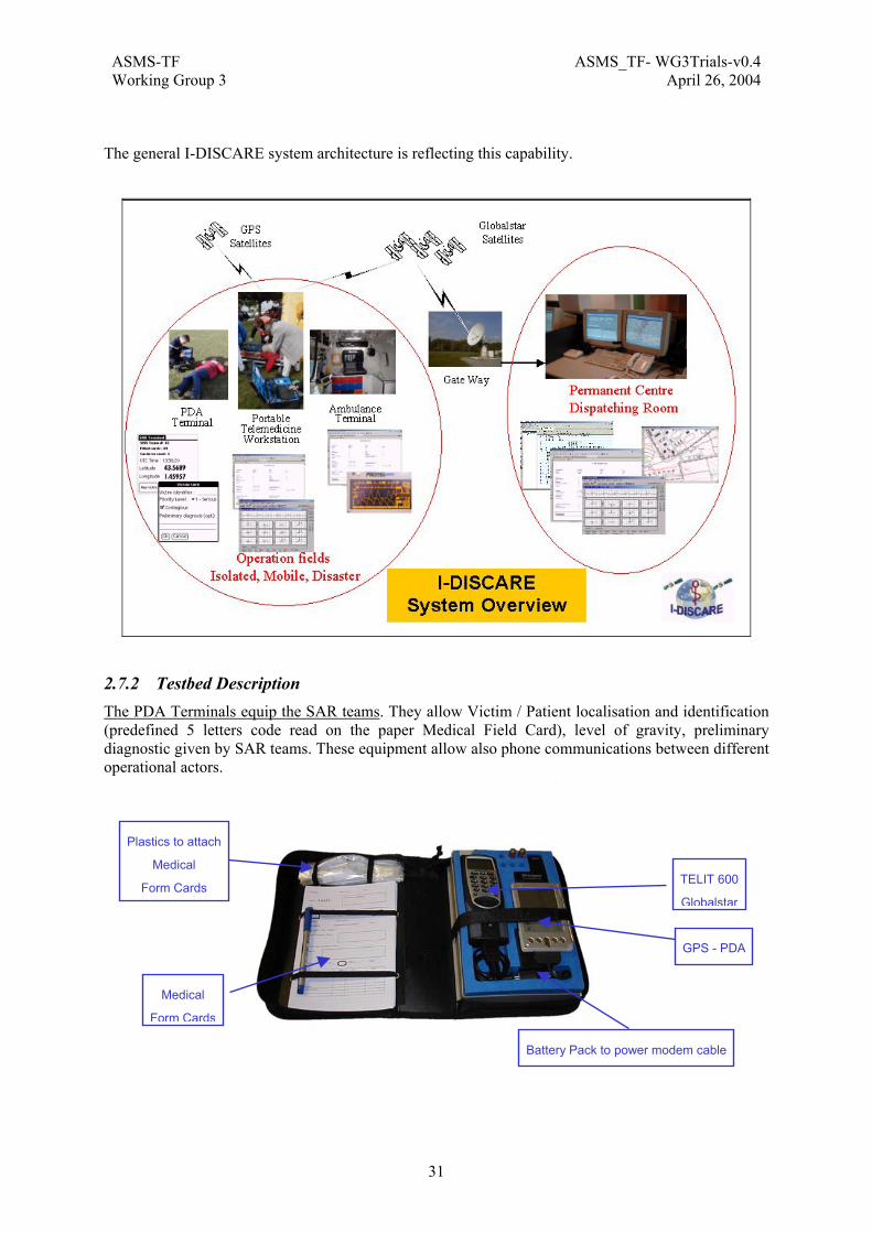
ASMS-TF ASMS_TF- WG3Trials-v0.4Working Group 3 April 26, 2004
31
The general I-DISCARE system architecture is reflecting this capability.
2.7.2 Testbed Description The PDA Terminals equip the SAR teams. They allow Victim / Patient localisation and identification (predefined 5 letters code read on the paper Medical Field Card), level of gravity, preliminary diagnostic given by SAR teams. These equipment allow also phone communications between different operational actors.
Medical
Form Cards
Plastics to attach
Medical
Form Cards
GPS - PDA
TELIT 600
Globalstar
Battery Pack to power modem cable

ASMS-TF ASMS_TF- WG3Trials-v0.4Working Group 3 April 26, 2004
32
The Portable Telemedicine Workstations equip the medical staff at the at the advanced meeting point. They allow objective medical data transmission, Electrocardiogram (ECG) 10 leads, Non Invasive Blood Pressure (NIBP), Blood Oxygen Saturation (Sa02), Heart Rate (HR), body temperature (T°) and localisation, always attached with the unique victim / patient identification. The satellite cell phone can be used also for voice communications between different operational actors.
The Ambulance terminal equip the ambulance insuring the evacuations of victims / patients toward care centres. They allow objective medical data transmission, ECG 3 leads, NIBP, Sa02 HR, T° and ambulance localisation, always attached with the unique victim / patient identification. The satellite cell phone can be used also for voice communications between different operational actors.
PC power
adapter
ECG
GPS
Qualcomm
Globalstar
PC
Oxymeter
TELIT 611
Data modem
ECG Spare
Batteries
Blood Pressure
Automatic cuff

ASMS-TF ASMS_TF- WG3Trials-v0.4Working Group 3 April 26, 2004
33
Propaq monitor
Connector
to the ambulance12
Medical Forms Cards + User
manuals
GPS
PC
Globalstar
Qualcomm
Magnetic antenna
GPS and GB
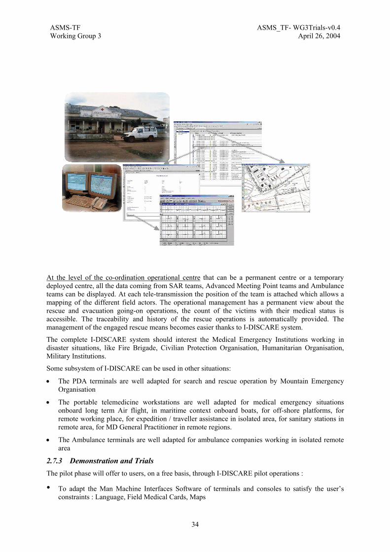
ASMS-TF ASMS_TF- WG3Trials-v0.4Working Group 3 April 26, 2004
34
At the level of the co-ordination operational centre that can be a permanent centre or a temporary deployed centre, all the data coming from SAR teams, Advanced Meeting Point teams and Ambulance teams can be displayed. At each tele-transmission the position of the team is attached which allows a mapping of the different field actors. The operational management has a permanent view about the rescue and evacuation going-on operations, the count of the victims with their medical status is accessible. The traceability and history of the rescue operations is automatically provided. The management of the engaged rescue means becomes easier thanks to I-DISCARE system.
The complete I-DISCARE system should interest the Medical Emergency Institutions working in disaster situations, like Fire Brigade, Civilian Protection Organisation, Humanitarian Organisation, Military Institutions.
Some subsystem of I-DISCARE can be used in other situations:
• The PDA terminals are well adapted for search and rescue operation by Mountain Emergency Organisation
• The portable telemedicine workstations are well adapted for medical emergency situations onboard long term Air flight, in maritime context onboard boats, for off-shore platforms, for remote working place, for expedition / traveller assistance in isolated area, for sanitary stations in remote area, for MD General Practitioner in remote regions.
• The Ambulance terminals are well adapted for ambulance companies working in isolated remote area
2.7.3 Demonstration and Trials The pilot phase will offer to users, on a free basis, through I-DISCARE pilot operations :
• To adapt the Man Machine Interfaces Software of terminals and consoles to satisfy the user’s constraints : Language, Field Medical Cards, Maps
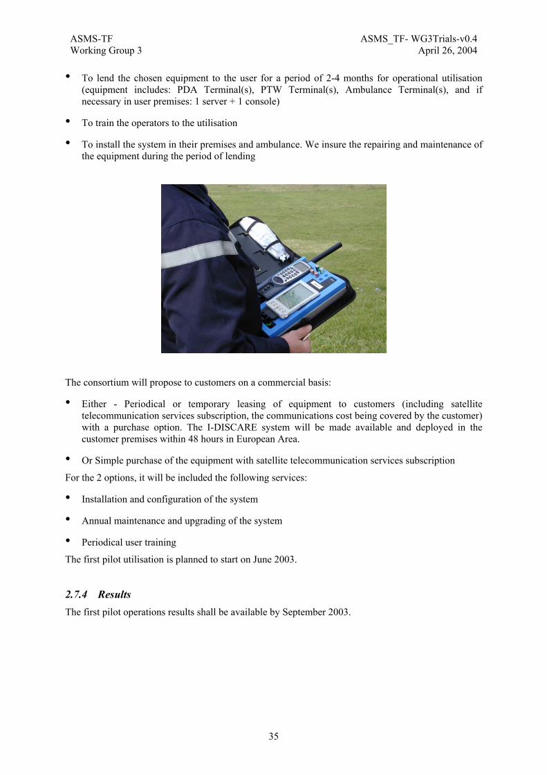
ASMS-TF ASMS_TF- WG3Trials-v0.4Working Group 3 April 26, 2004
35
• To lend the chosen equipment to the user for a period of 2-4 months for operational utilisation (equipment includes: PDA Terminal(s), PTW Terminal(s), Ambulance Terminal(s), and if necessary in user premises: 1 server + 1 console)
• To train the operators to the utilisation
• To install the system in their premises and ambulance. We insure the repairing and maintenance of the equipment during the period of lending
The consortium will propose to customers on a commercial basis:
• Either - Periodical or temporary leasing of equipment to customers (including satellite telecommunication services subscription, the communications cost being covered by the customer) with a purchase option. The I-DISCARE system will be made available and deployed in the customer premises within 48 hours in European Area.
• Or Simple purchase of the equipment with satellite telecommunication services subscription
For the 2 options, it will be included the following services:
• Installation and configuration of the system
• Annual maintenance and upgrading of the system
• Periodical user training
The first pilot utilisation is planned to start on June 2003.
2.7.4 Results The first pilot operations results shall be available by September 2003.

ASMS-TF ASMS_TF- WG3Trials-v0.4Working Group 3 April 26, 2004
36
2.8 THE MAESTRO PROJECT
2.8.1 Overview MAESTRO is an Integrated Project under EU Framework Program 6 for Research and Development. The project belongs to the thematic priority: ”Information Society Technologies”, and is in line with the strategic objective “Mobile & Wireless System Beyond 3G”. MAESTRO has officially started on 1st of January 2004 and will run over a period of 2 years.
The project objectives include:
• Consolidate Satellite Digital Multimedia Broadcast service, mission & commercial requirements
• Define the architecture supporting SDMB key functions and performances
• Validate key SDMB functions and performances with a test bed
• Investigate potential evolutions, novel methods and techniques which may benefit to the innovative satellite/terrestrial infrastructure
• Carry out standardisation and regulatory activities required for an effective SDMB system deployment
• Promote the system with dissemination and training
A MAESTRO test bed will be developed based on the sub-system specification and trial specifications. It will enable to carry out laboratory tests as well as field trials to validate the SDMB system key functions and performances.
In order to be able to develop the test bed and carry out validation tests within the 2 years of the project, the project plans:
• To re-use major parts of the IST/FP5 MoDiS project’s experimental platform.
• To define successive functional releases corresponding to a set of features for implementation in the MAESTRO test bed sub-system.
Three releases will be defined during the course of the project. However, only the first two functional releases which will be implemented on the test bed.
The implementation in the MAESTRO test bed of the 3rd release is foreseen within a subsequent FP6 project.
The Maestro consortium consists of Alcatel Space (F) -project coordinator-, Motorola Semiconductor SAS (F), LogicaCMG UK Limited (UK), AGILENT TECHNOLOGIES BELGIUM S.A. (B), Ascom Systec AG (CH), University College London (UK), UNIVERSITY OF BOLOGNA (I), The University of Surrey (UK), Fraunhofer Gesellschaft zur Förderung der angewandten Forschung e.V. (D), Udcast (F), SPACE HELLAS S.A. (EL), ERCOM ENGINEERING RESEAUX COMMUNICATIONS (F), AWE COMMUNICATIONS GMBH (D), GFI CONSULTING (F), SES GLOBAL (L), BRITISH TELECOMMUNICATIONS PLC (UK), E-TF1 (F), BOUYGUES TELECOM (F), Alcatel CIT (F), Alcatel SEL AG (D).
More details can be found on the MAESTRO website: http://ist-maestro.dyndns.org
2.8.2 Testbed Description The system validation will rely on:
• Laboratory trials and field trials using test bed based on an upgraded version of the MoDiS experimental platform described in the figure here below.
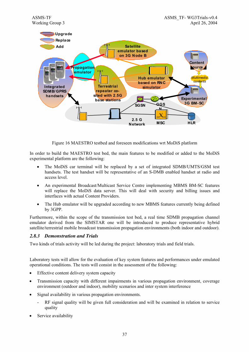
ASMS-TF ASMS_TF- WG3Trials-v0.4Working Group 3 April 26, 2004
37
SGSN GGSN
Terrestrialrepeater co-
sited with 2.5Gbase stations
HLR
Experimental3G BM-SC
MSC
Satelliteemulator basedon 3G Node B
Hub emulatorbased on RNC
simulator
2.5 GNetwork
IntegratedSDMB/ GPRS
handsets
Contentsource
Multimediacontents
ReplaceUpgrade
Propagationemulator
Add
Figure 16 MAESTRO testbed and foreseen modifications wrt MoDiS platform
In order to build the MAESTRO test bed, the main features to be modified or added to the MoDiS experimental platform are the following:
• The MoDiS car terminal will be replaced by a set of integrated SDMB/UMTS/GSM test handsets. The test handset will be representative of an S-DMB enabled handset at radio and access level.
• An experimental Broadcast/Multicast Service Centre implementing MBMS BM-SC features will replace the MoDiS data server. This will deal with security and billing issues and interfaces with actual Content Providers.
• The Hub emulator will be upgraded according to new MBMS features currently being defined by 3GPP.
Furthermore, within the scope of the transmission test bed, a real time SDMB propagation channel emulator derived from the SIMSTAR one will be introduced to produce representative hybrid satellite/terrestrial mobile broadcast transmission propagation environments (both indoor and outdoor).
2.8.3 Demonstration and Trials Two kinds of trials activity will be led during the project: laboratory trials and field trials.
Laboratory tests will allow for the evaluation of key system features and performances under emulated operational conditions. The tests will consist in the assessment of the following:
• Effective content delivery system capacity
• Transmission capacity with different impairments in various propagation environment, coverage environment (outdoor and indoor), mobility scenarios and inter system interference
• Signal availability in various propagation environments.
- RF signal quality will be given full consideration and will be examined in relation to service quality
• Service availability

ASMS-TF ASMS_TF- WG3Trials-v0.4Working Group 3 April 26, 2004
38
• Coverage
• Reception of content via SDMB system in a transparent manner with respect to simultaneous mobile network operation in idle mode.
• The efficiency of the reliable transport mechanism with respect to link error conditions and protocol settings measuring the impact of
- Interleaving
- FEC ratios on system throughput and reliability that will allow detecting optimal parameter settings.
• Soft hand-over
• Efficient terminal dual system operation
- SDMB reception during mobile operation
• End-to-end streaming service delivery
Field trials will also be carried out to verify the system performances and behaviour in selected real environments and operational system configurations, using the MAESTRO test bed.
The list of test to be carried out in field trials will be decided during the course of the project. Particularly the following will be considered:
• SDMB/GPRS Dual system operation
• SAT/IMR synchronisation
• Soft hand-over transmission (Rake receiver combining)
2.8.4 Results First official results from the trials are expected during the first semester 2005.

ASMS-TF ASMS_TF- WG3Trials-v0.4Working Group 3 April 26, 2004
39
2.9 THE MOBILITY PROJECT
2.9.1 Overview The basic goal of the MOBILITY project is to provide live TV and multimedia satellite services to people on the move, for the cases in which satellite will be the adequate solution (in particular, the maritime scenario).
Being a very novel and desired service for the European citizens, the importance of the MOBILITY project for improvement of the working, living and travelling conditions of European citizens is obvious. The service coverage would be limited in the frame of this project to the European maritime areas. Currently deployed digital TV satellites represent the optimal option to offer a pan-European mobile live TV service at once and with a quickly deployable strategy. For the provision of the envisaged service a number of GEO satellite broadcasting TV programs are already in orbit. The service can start soon, because DVB-S real time TV signals are already available all over Europe.
Main functional requirements for the proposed service are real time high quality digital TV, delivered anywhere in Europe, and with service availability similar to those, typical in fixed service. Typically, a DVB-S multiplex signal - containing several digital TV programmes in 36MHz of bandwidth - has around 38Mbps for specific conditions of coding. As the receiver is intended to be a single product for most of the mobile applications (at least a single one for all maritime scenarios), a small outdoor unit is required. Outdoor units of current receivers are not usable, thus there will be a need for some development work on new outdoor units that are able to track constantly a GEO satellite regardless of mobile platform movement. The frequency band selected for the purpose of radio-frequency developments of outdoor units is Ku-band (10.7-12.75 GHz), which matches most of the commercial satellite systems, either in operation or planned. The receiver will cover this bandwidth and receive in both polarisations.
2.9.2 Testbed Description A number of trials (at West and East European territories) has been conducted on board to evaluate the satellite TV service and to demonstrate the level of end-user acceptability.
DVB group suggests the measurements that should be taken of a digital television signal to make sure that its quality is satisfactory. They are often referred to collectively as the ‘DVB health check’. The recommended measurements are many and diverse: the buffer errors, the number of synchronism packets, the clock phase errors, C/N, etc.
Since DVB-S signal is the same as the one used for residential reception (commercial available) the purpose of trials on mobile environment are aiming into verifying the receiving system’s capability in such environments and not validating MPEG 2 transport stream. In this case, the recommended measurements are targeting into reception performance and are the following:
• Digital channel power
• Carrier-to-noise ratio
• Bit error rate
A satellite signal analyser optimised for measurements in television signals has been used for fundamental measurement set up. This modular instrument enables the user to analyse both analog and digital TV transmissions, where at the same time meets the strict technical requirements imposed by DVB.
In order to obtain reliable measurements, ship’s movement behaviour has been recorded, as it is the main aspect that will interfere with the antenna system performance. For this reason the readings of the movement sensors that actually control the device that holds the pointing algorithm, will be also monitored and recorded.

ASMS-TF ASMS_TF- WG3Trials-v0.4Working Group 3 April 26, 2004
40
These parameters give a clear view of ship’s behaviour, velocity, direction, inclination etc, as well as the transition rate, enabling us to extract meaningful conclusion for the performance of the antenna system.
Sufficient representative field-trial data have been acquired in order to improve the accuracy of the values adopted for critical service-quality numerical values (e.g. minimum field-strength, C/N and BER) and that will be compared with theoretical ones derived from link budget estimations.
The following figure shows the final signal processing scheme to be done during the Trials. The IRD’s output (the one provided by Via Digital) will be connected to the existing system by taking advantage of the existing analogue satellite TV installation. IRD output would be RF modulated on a specific channel and reach the ship’s TV distribution. We do not expect to experience problems with signal levels as receiver’s output levels are more or less standardized.
Figure 17 MOBILITY Measurement Topology
The measurement concept is described in the following steps, according to the recommendations:
• Frequency Tune To The Center Of Transponder
• Channel Power Estimation
• C/N Estimation
• BER Estimation
The previous process will be followed during the entire tip duration. Measurements data will stored at the hard disk and will be post-processed after trials had finished.
2.9.3 Demonstrations and Trials Trials are planned to be performed in the Greek and Spanish region. MOBILITY antenna will be tested onboard Blue Star I in the route from Piraeus – Athens to Rhodes Island in the Aegean Sea or in the Adriatic area from Ancona to Patras. The duration of the trials is two round way trips. Tests have been carried out in the Atlantic Ocean onboard Juan J. Sister in the route Cádiz – Canary Islands during a round trip.
Using the test bed that was described above, antenna reception parameters will be monitored and logged.
Additionally the user’s opinion will be extracted during the trials. Ship’s passengers could facilitate with satellite TV reception during the trials through the specially network that was deployed for the System demonstration. Their opinions and suggestions will be collected my means of questionnaire and face to face conversations aiming to guide us into further system and service development.

ASMS-TF ASMS_TF- WG3Trials-v0.4Working Group 3 April 26, 2004
41
During the week of January 14th to 20th 2003, MOBILITY carried out its first trials in the trip that weekly realises the Juan J. Sister ship between Cádiz and several island in the Canaries. The trials involved nine people working hardly during eight days on the top deck of the ship. A full checking of every part in the MOBILITY system was carried out and the results are summarised in this table:
Array Working properly
RF part Working. Noise higher than in lab (see details in Annex II part C)
Engines Working properly
Control Boards Working properly
PAT integration Working properly
PAT software Working properly
PAT-Antenna integration Working properly
Measurement equipments Working properly
Measurement acquisition Working properly
Signal reception All the trip
Signal decoding Continually in areas where the satellite coverage is high
In this way the first trial phase has been concluded successfully, leaving the system in standby till the technical verification. After it, the system will be moved to the STRINTZIS LINES ship in order to carry out the second trials phase between Ancona (Italy) and Patras (Greece).
At the end of trials the logfiles from this system along with the logfiles produced from DLR’s PAT monitoring system will be combined in order to correlate the ship’s behavior and the antenna’s performance, as the major criterion that makes MOBILITY antenna different from the existing static reception antennas is motion. For the datalogging process custom made software will be used by both Space Hellas and DLR. Both logfiles will be synchronized by means of universal time stamp (UTC time).
Data of these logfiles will be manipulated using commercial engineering software applications like Matlab and GIS tools (MapPoint and MapInfo) and visualized graphs of the antenna performance in respect to ships movement will be produced, so that it is easily recognized that the antenna is operating within acceptable ranges.
Statistical diagrams and detailed evaluation figures that will validate the service quality and provide the means for the successful implementation of a mobile DVB-S system will be extracted.
2.9.4 Results The figure below illustrates uninterrupted reception of Hispasat digital satellite TV signal. It is clear that during the entire measurement period BER after Viterbi remained slightly higher than QEF threshold, which is a relative value of quality. Finally it seems that from the user’s point of view such a figure is quite useless as what really matters to him is uninterruptible TV reception! For the case of MOBILITY trials we experienced uninterrupted satellite reception for a long time as the related videos shown.
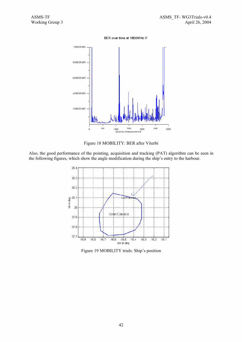
ASMS-TF ASMS_TF- WG3Trials-v0.4Working Group 3 April 26, 2004
42
Figure 18 MOBILITY: BER after Viterbi
Also, the good performance of the pointing, acquisition and tracking (PAT) algorithm can be seen in the following figures, which show the angle modification during the ship’s entry to the harbour.
Figure 19 MOBILITY trials: Ship’s position
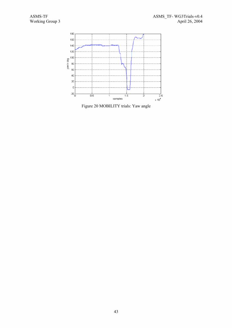
ASMS-TF ASMS_TF- WG3Trials-v0.4Working Group 3 April 26, 2004
43
Figure 20 MOBILITY trials: Yaw angle

ASMS-TF ASMS_TF- WG3Trials-v0.4Working Group 3 April 26, 2004
44
2.10 THE MODIS PROJECT
2.10.1 Overview MoDiS is an R&D project partially funded by the European Commission’s 5th Framework Programme as part of the Information Society Technologies (IST) Programme, Key Action IV Essential Technologies and Infrastructures. MoDiS has officially started on 1st of April 2002 and will run over a period of 30 months.
MoDiS intends to proof the Satellite Digital Multimedia Broadcasting (S-DMB) System concept, which consists of a unidirectional satellite component added to the 3G terrestrial infrastructure and aiming at delivering point to multi-point traffic directly to 3G mobile terminals.
To reach this goal, the project consortium aims at the deployment of an experiment platform representative of the S-DMB satellite component. The platform is made of a satellite emulator and several terrestrial repeater emulators fed by a data centre providing broadcasting/multicasting IP streams of multimedia content. The platform interacts with a commercial cellular network to demonstrate the interoperability and complementary of satellite and terrestrial networks.
The MoDiS consortium consists of Alcatel Space (F) -project coordinator-, Daimler Chrysler (D), University of Surrey (UniS), Agilent Technologies (B), Elitel (I), UDCast (F), Space Hellas (EL), Ercom (F), Alcatel Bell Space (B), Monaco Telecom (MC).
Detailed information about MoDiS and S-DMB can be found at the web site http://www.ist-modis.org/.
2.10.2 Testbed Description The proof of the S-DMB system concept is achieved through trials performed within the MoDiS project. The architecture of the S-DMB system is recalled below:
RNC
Contentprovider
Satellite feeders in FSS
band (direct + indirect)
ContentNetworking
SDMB satellite
UTRA FDD W
-CDMA in MSS
band
SDMBenabled
UEGmb*/ Gi
UMTS airinterface
BSC
SGSN GGSNNode B
BTS HLR
SDMBdata
server
GSM/ GPRSair interface
SDMB Hub
MSC
IMR
feed
er in
FSS
ban
d
Gmb/ Gi
Iub
Terrestrialrepeater
Abis
direct
indirect
Figure 21 S-DMB enabled 3GPP architecture
The experiment consists to set-up of a representative network of the S-DMB system in Monaco, as shown in the following figure:

ASMS-TF ASMS_TF- WG3Trials-v0.4Working Group 3 April 26, 2004
45
MoDiSterminal
SGSN GGSN
Terrestrialrepeater
MoDiS dataserver
3GPP airinterface
Satellite /Hubemulator
2.5G / 3Gterminal
SDMBreceiver
Contentclient
HUBnetwork fct
emulator
2.5 G / 3G network
Multimediacontents
Distribution link
Interactive link
Car
Figure 22 MoDiS testbed
When comparing this platform with the S-DMB architecture, the differences are the following:
• The satellite and the transmission part of the hub have been replaced by an emulator.
Due to the lack of existing satellite being able to provide enough power and bandwidth in the L/S frequency bands, the S-DMB satellite will be replaced by an UMTS Node B located on an high altitude place. This transmitter will be set to have a transmission power equivalent to a satellite. For the Trial, transmission will be performed in terrestrial IMT2000 frequency band.
The Hub network function emulator performs the same baseband function as defined for the S-DMB hub. The Hub network functions correspond to a RNC simulator featuring broadcast / multicast support and adapted to MoDiS platform constraints.
• Terrestrial repeaters are transparent, meaning they produce the same signal (same frequency , same scrambling code) as the satellite emulator. 2 transparent terrestrial repeaters will be used in the MoDiS testbed.
• The interactive link is provided by a 3G network.
• The MoDiS terminal is not an integrated handset, but merely an assembly of equipment: S-DMB receiver, laptop, PDA, 3G handset, GPS receiver. 2 MoDiS terminal will be used in the testbed : one in a trolley and the other one in a car.
• The MoDiS data server is simplified versus what should be done in S-DMB; the connections to real content providers are simulated and the service announcement will not be implemented.
2.10.3 Demonstration and Trials The experimental platform has the following main goals:
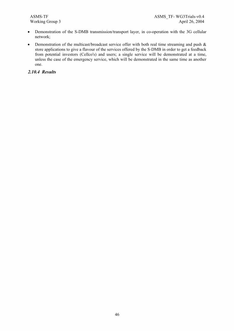
ASMS-TF ASMS_TF- WG3Trials-v0.4Working Group 3 April 26, 2004
46
• Demonstration of the S-DMB transmission/transport layer, in co-operation with the 3G cellular network;
• Demonstration of the multicast/broadcast service offer with both real time streaming and push & store applications to give a flavour of the services offered by the S-DMB in order to get a feedback from potential investors (Cellco's) and users; a single service will be demonstrated at a time, unless the case of the emergency service, which will be demonstrated in the same time as another one.
2.10.4 Results
ASMS-TF ASMS_TF- WG3Trials-v0.4Working Group 3 April 26, 2004
47
2.11 THE RELY PROJECT
2.11.1 Overview The RELY project is an European Commission IST project that has the following objectives:
• To demonstrate the provision of both real time and multicast push-and-store services to in-vehicle mobile terminals using an hybrid satellite-terrestrial broadcasting system on a European dimension.
• To provide EGNOS service in an innovative, cost effective and global manner using standard mass marketed satellite Digital Broadcasting (S-DB) features and hardware. The goal is to contribute to the development and the operations of the ”integrity” market and to explore new applications. RELY will also facilitate the development of EGNOS outside Europe.
A set of services using the different satellite technologies will be defined and implemented. Those services are of the following types:
1. Digital audio broadcasting;
2. Web-casting;
3. Enhanced navigation services;
4. Fleet management services.
Specific sub-objectives of the project are:
• To validate a fully integrated EGNOS and Satellite Digital Broadcast (S-DB) hardware and services in an in-vehicle environment;
• To integrate S-DB, GSM and EGNOS features into one platform suitable for the provision of navigation and fleet services;
• To provide new means for improving data reception compared to current systems to ensure better service availability especially in urban canyons, tunnels, etc;
• To demonstrate wireless navigation and fleet-management services provided via S-DB and integrating EGNOS positioning;
• To assess commercial viability of the service concept for the European market;
• To pave the way towards the deployment of a European S-DB system for mobiles.
2.11.2 Testbed Description The RELY system architecture is given in the following figure. The system can be divided into 5 different segments:

ASMS-TF ASMS_TF- WG3Trials-v0.4Working Group 3 April 26, 2004
48
AudioStream
MultimediaContent
PushContent
EGNOS
HRR
EGNOS
RELY
SER
VER
GAT
EWAY
GPS Signal
BORG
PDA
APPLICATIONSHW SW
Browser
...
OFDM
SpaceSegment
ContentProductionSegment
UplinkSegment
Terminal Segment
128
kbps
(2x6
4kbp
s if T
D)
Single CarrierQPSK
UPL
INK
EART
H S
TATI
ON
AfriStar (21°E)
RELYRouter
TerrestrialRepeaterSegment
Content Production Segment
The Content Production Segment (CP-SEG) is composed of several service providers facilities connected to the up-link station. The CP-SEG mission is :
• To get or create the content,
• To label batch or stream content to enable intelligent filtering in the terminal,
• To transmit the labelled content to the Up-Link Segment (UL-SEG).
Up-Link Segment
The Up-Link Segment (UL-SEG) is composed of one station located in Erlangen [G].
All parts specific to RELY will be provided from the RELY project, i.e.:
• The RELY Server (including the RELY Scheduler) at Intellicast facilities (Luxembourg)
• The Gateway (including the RELY Streamer)
• The Studio terminal and the Modified FLS Tester
The UL-SEG mission is :
• To receive the content from several service providers,
• To implement a transmission strategy adapted to each category of content,
• To multiplex the data received from several service providers,
• To implement time-diversity (i.e. the content is broadcast twice with 4s delay in order to withstand short interruptions at the terminal level when driving under a bridge on behind buildings).
Space Segment
The Space Segment (SP-SEG) is composed of the AfriStar satellite located on a GEO orbit . Broadcasting will take place on the processed channel of the North East beam.
The SP-SEG mission is:
• To receive the signal from the up-link station in X-Band,
• To amplify and transmit the signal down to earth in L-Band.

ASMS-TF ASMS_TF- WG3Trials-v0.4Working Group 3 April 26, 2004
49
Terrestrial Repeaters Segment
The Terrestrial Repeaters Segment (RP-SEG) is composed of up to two terrestrial repeaters located in Paris and one in Erlangen. Terrestrial repetition will take place in L band (1452 to 1492 MHz). The RP-SEG mission is:
• To receive and demodulate the signal from the satellite,
• To modulate and re-transmit the signal with a COFDM waveform
Terminal Segment
The Terminal Segment (TR-SEG) will be integrated in demonstration vehicles. The vehicles will be driven in urban and rural environment. The TR-REG mission is:
• To receive and combine the signals received from the satellite and/or the repeaters.
• To filter the content and cache only the content relevant to the end-user (according to pre-defined user profile).
• Provide the MMI to browse the cached content, access the streamed content, and also to configure the user profile.
• To enable easy synchronisation with handheld devices like pocket PC
• To estimate an enhanced vehicle location as well as location integrity information thanks to the EGNOS correction data provided by the satellite radio and to a classical GPS receiver.
2.11.3 Results The project will address the following tasks:
• Identify the requirements of users, car manufacturers, fleet owners;
• Define specifications for technical elements, including an overall system architecture and specifications for the interfaces between vehicles and the infrastructure elements;
• Test the system in a selection of vehicles and terminal platforms in different scenarios and locations across Europe;
• Establish the technical, organisational and commercial feasibility of the service concept and propose first business plans for each of the organisation involved in the service delivery and operation.
Indeed the creation of awareness of the benefits of the projects approach among a very wide range of organisations related to the satellite business and service providers is crucial to the take-up of its proposed solutions.
The milestones and expected results will be the following:
• An agreed set of technical specifications describing the integration of S-DB and EGNOS technologies;
• Four prototype terminals integrating EGNOS and S-DB signals to provide added value telematic services (one for the French sites [in the Citroen C8] and three for the German site [BMW, DaimlerChrysler, FhG Laboratory]);
• A successful trial of telematic services on the project prototype;
• A service architecture based on user needs leading to a list of winner choices;
• Technical evaluation of the project results;
• Service quality assessment based on the results emerging from the demonstration project;
• Elements of business model to enable further commercial and technical implementation.

ASMS-TF ASMS_TF- WG3Trials-v0.4Working Group 3 April 26, 2004
50

ASMS-TF ASMS_TF- WG3Trials-v0.4Working Group 3 April 26, 2004
51
2.12 THE ROBMOD PROJECT
2.12.1 Overview The ESA ROBMOD project (Robust Modulation & Coding for Personal Communications Systems ) aims at defining and validating a candidate physical-layer approach for the satellite component of UMTS. ROBMOD saw the participation, under Space Engineering (I) prime-contractorship, of Ascom (CH), CoRiTel (I), IMST (D), Politecnico di Torino (I) and SquarePeg (C).
The background theoretical work mainly consisted of extensive trade-off and simulation activities, covering important issues such as frame structures, diversity advantage assessment in realistic conditions, acquisition & synchronization, chip-synchronous reverse-link feasibility, power control performance, multi-user interference mitigation techniques, impact of non-linearity, BER / FER performance assessment in a real channel, ad-hoc coding techniques for speech & video transmission, embedded user-location functions. On the basis of ROBMOD results, ESA submitted to ITU a standardization proposal for two CDMA-based Radio Transmission Technologies, i.e. a SW-CDMA solution exploiting pure CDMA and suitable for FDD operation, and a S-CTDMA solution exploiting CDMA/TDMA and suitable for TDD operation.
Subsequently, a very comprehensive hardware facility (the Test Bed) was specified and implemented. Such facility consists of physical devices generating and modifying signals, as required to faithfully reproduce the effects experienced in a real via-satellite SW-CDMA operational environment. It also includes some basic upper-layer functions, such as to permit realistically demonstrating, in real-time, an IP-based application though the Test Bed. The ESA choice to concentrate mainly on physical-layer issues followed the consideration that, especially for the satellite case, this layer will constitute one of the hardest challenges with regard to successful UMTS deployment; on the other hand most of the upper-layers will likely be common to those of the terrestrial component.
2.12.2 Testbed Description The ROBMOD Test Bed models a complete bi-directional Gateway ↔ Terminal satellite link, interfaced, for demostration purposes, to two external PCs respectively running the client function (at the mobile user side) and the server function (at the fixed user side) of an IP-based application, as shown in Figure 23.
IP application
ROBMOD TEST BED
FORWARD - LINK (FL) (Gateway-to-Terminal)
Fixed user
IP application
Mobile userRETURN - LINK (RL)
(Terminal-to-Gateway)
Dynamic Constellation Simulator
Gateway side Terminal side
- CDMA chip-rate: 3.84 Mchip/s- Information rate: 64 Kbit/s (being upgraded to 128 Kbit/s in the frame of VIRTUOUS)
Figure 23 ROBMOD Testbed links between terminal and gateway

ASMS-TF ASMS_TF- WG3Trials-v0.4Working Group 3 April 26, 2004
52
The Test Bed provides a hardware-based emulation of virtually all effects occurring in a real SW-CDMA environment. The following main features are offered:
• multi-satellite diversity and beam-handover with coherent combining. For these purposes, hardware emulation of three independent and fully-programmable “satellite paths” is provided, each including seven “beam paths”, also programmable. On the forward-link, the Gateway transmit-side incorporates three data-channel modulators, while the Terminal demodulator has three fingers. On the reverse-link, the Gateway demodulator has four fingers;
• realistic channel representation, by means of hardware providing independent emulation of free space losses, delay, Doppler, user-defined propagation channel, etc.;
• multiple-user access interference, simulated by hardware CDMA codes generators. not just by thermal noise;
• power control implemented via real signalling channels; frequency control loops;
• adaptive interference suppression for the Gateway demodulator (Blind-MOE algorithm);
• selection of FEC codes (convolutional, 3GPP turbo code);
• support of most physical and logical channels specified for SW-CDMA.
The physical layer is basically managed on circuit-basis; furthermore some upper-layer functions were included (e.g. call control and satellite- & beam-handoff management via ad-hoc signalling channels).
A Dynamic Simulator makes the Test Bed parameters evolve, for having it to reproduce, in real-time, the link parameters and the geometric characteristics of any user-defined constellation, including the LEO ones.
The Test Bed incorporates interfaces at IF level, for connection to Gateway and Terminal radio front-ends, in view of future tests via a real satellite.
A software-intensive implementation strategy has been adopted, to allow varying, to a good extent, the air-interface parameters and the test conditions, in the perspective of tracking specification changes being progressively introduced by 3GPP. A top-level block diagram is presented below.
GW-side application interface
Interf. Gener.
Modul.
GW MODEM ASSEMBLY
TEST BED CONTROL ASSEMBLY
MMI
Handoff Control
Interf.
Call Control
GW UPPER-LAYERS ASSEMBLY
Interf. Mitig.
Demod.
MT MODEM ASSEMBLY
Channel Simul.
CHANNEL SIMULATOR ASSEMBLY
MT UPPER-LAYERS ASSEMBLY
DYNAMIC SIMULATOR ASSEMBLY
Processor MMI
MT-side application interface
Handoff Control
Call Control
Interf.
Processor
Channel Simul.
Interf. Gener.
Modul.Demod.
REVERSE LINK
FORWARD LINK
Figure 24 ROBMOD high-level architecture
More detailed information on ROBMOD can be found in [ROB, 3].
2.12.3 Demonstration and Trials TBC

ASMS-TF ASMS_TF- WG3Trials-v0.4Working Group 3 April 26, 2004
53
2.12.4 Results The ROBMOD Test Bed constitutes an important facility for SW-CDMA physical-layer validation and tune-up, even in conjunction with real satellites. Its ability to reproduce different constellations and system configurations, as well as the possibility to adapt it to different physical-layer parameters, make the Test Bed a tool of quite general use.
The ROBMOD Test Bed has extensively been used in a laboratory context to verify the results obtained by computer simulations with regard to the SW-CDMA physical layer. This was possible also in the context of multi-satellite constellations, thanks to the available facilities which permit to also faithfully reproduce a real LEO and GEO operating environment, including spot- and satellite-handoffs.
Tests were also carried out by programming the channel simulators so as to model different propagation environments, and good consistency between experimental results and simulation data was always obtained.
A second unit of the ROBMOD Test Bed has been built upon ESA request, which was installed in the ESTEC laboratory, where more tests are being carried out.
ASMS-TF ASMS_TF- WG3Trials-v0.4Working Group 3 April 26, 2004
54
2.13 THE SAILOR PROJECT
2.13.1 Overview SAILOR is an IST project co-funded by the European Commission within 5th Frame Program. The project started on 1/9/2002 and will end on 28/2/2005. SAILOR represents a key contribution to the European policy for the development of new telecommunications services and for the global building-up of the European Information Society.
Technological innovation and the growing demand for global personal communication services have opened opportunities, in space and time, for new commercial applications of satellite. This scenario will be characterized by the offer and supply of a set of new services, provided through the available space infrastructure. This market segment will be able to exploit the special features of satellite communication: fast and complete geographic coverage, service provision (not only voice traffic) to wide areas which lack cellular service due to insufficient traffic density or areas with no telecommunications service at all.
SAILOR aims at demonstrating the feasibility and viability of providing an appealing service mix over an integrated T-S-UMTS network. In order to reach this aim, the SAILOR project has to develop a complex mix of advanced mobile and wireless methodologies and technologies, which include:
• a market analysis for the identification of the most suitable service mix and traffic configuration/statistics which can be supported by the integrated T-S-UMTS network,
• the implementation of innovative multicast procedures for the integrated T-S-UMTS network,
• the implementation of an advanced RASN based UMTS Core Network suitable to support the multicast procedures and that can naturally interwork with both a T-UMTS and S-UMTS Access Network , including Radio Access Bearer (RAB) Management, Mobility Management and Session Management,
• the implementation of a fully innovative software Cellular Planning Tool for the optimization of the integrated T-S-UMTS cellular layout,
• the implementation of advanced CAC procedures which, in conjunction with the Cellular Planning Tool, allow the optimization of the exploitation of the radio resources of the integrated T-S-UMTS network.
The partners of the project include: Telespazio, University of Rome La Sapienza, Space Engineering, Eutelis Consult Italia, University of Aquila, University of Aachen, Siemens Austria, Ericsson Hellas, Integracion y Sistemas de Medida and Ascom.
2.13.2 Testbed Description The SAILOR project will implement a demonstrator, aiming at a complete integration between T-UMTS & S-UMTS. The demonstrator will add new functionalities that will exploit more efficiently the utilization of the satellite segment, provide a meaningful environment to implement more advanced multimedia services (broadcast, multicast) and allow a more advanced implementation of the UMTS Core Network.
Figure 25 shows the outline of the overall SAILOR target system architecture. The figure shows that the SAILOR architecture consists of a Core Network and two Access Networks, namely a Terrestrial UMTS Access Network (based on the terrestrial W-CDMA standard) and a Satellite UMTS Access Network (based on the satellite W-CDMA proposal developed by the European Space Agency (ESA)).

ASMS-TF ASMS_TF- WG3Trials-v0.4Working Group 3 April 26, 2004
55
UMS
HLR
CSCF = Call State Control FunctionLAN = Local Area NetworkHLR = Home Location RegisterHSS = Home Subscriber ServerPC = Personal ComputerSIP = Session Initiation ProtocolUE = User EquipmentUMS = UMTS Mobility Server
HSS
RASN
CSCF (SIPProxy)
FeatureServer
Internet Multimedia (IM) subsystem
(Radio AccessSupport Node)
Fully IP-basedUMTS Core
Network
PC
TerrestrialUMTSAccess
Network
SatelliteUMTSAccess
Network
UTRAN (TerrestrialUMTS Radio Access
Network)
Satellite UMTSRadio Access
Network
Iu-ps Iu-ps
Terrestrial air interface
PC LANPC
Dual Mode terminal
Satellite air interface
Figure 25 SAILOR logical architecture
In more detail the SAILOR architecture which will be implemented, is depicted in Figure 26; the main elements are:
• A static cellular planning tool
• An Access Network Dynamic System Level Simulator
• An Access Network Protocol Simulator
• An Access Network Emulator
• A fully IP based Core Network, only connected to the AN Emulator via a standard interface

ASMS-TF ASMS_TF- WG3Trials-v0.4Working Group 3 April 26, 2004
56
•
CPT Simulator
CAC Simulator
UMS CSCF FS
IMS
IPIP
RASN1 RASN2
BS
1 2 N….
BS
1 2 N….1PC 1PC
RANAP RANAP
SIMULATOR DEMONSTRATOR/EMULATOR
AC
CE
SS N
ET
WO
RK
C
OR
E N
ET
WO
RK
MulticastA
lgorithms
Simulator
Protocol simulatorCPT
SimulatorCAC
SimulatorCPT
SimulatorCAC
Simulator
UMS CSCF FSUMS CSCF FS
IMS
IPIP
RASN1 RASN2
BS
1 2 N….
BS
1 2 N….1 2 N….
BS
1 2 N….
BS
1 2 N….1 2 N….1PC 1PC
RANAP RANAP
SIMULATOR DEMONSTRATOR/EMULATOR
AC
CE
SS N
ET
WO
RK
C
OR
E N
ET
WO
RK
MulticastA
lgorithms
Simulator
Protocol simulator
MulticastA
lgorithms
Simulator
Protocol simulator
Figure 26 SAILOR architecture
• Core Network: Fully IP based Core Network includes an Internet Multimedia (IM) subsystem and one Radio Access Support Node (RASN) where the Internet Multimedia Subsystem (IMS) present in the Core Network will be derived from VIRTUOUS/FUTURE, but will be upgraded for SAILOR purposes; in particular, since SAILOR is aimed at multicast services, it is expected that enhancements have to be made especially in the Feature Server (FS) and in the Call State Control Function (CSCF). The fully IP RASN based approach represents the central innovation of such a system, bringing the final user closer to the Internet. The Core Network will be actually implemented in the SAILOR Emulator.
• Access Network: in order to better perform the main SAILOR experiments, three different approaches will be followed for the development of the access network. First of all, SAILOR foresees the implementation of (i) a SW “Access Network Emulator”, mainly focused on multicasting functionality, and it will also be connected to the actual implemented fully IP based core network in the frame of the relevant experiment. Such an emulator will not deal with QoS management issues, and it will be provided with a certain enough number of SW emulated terminals needed to perform its tasks. Only some of the functionality designed and implemented in VIRTUOUS and FUTURE (for instance, the algorithms for the Power Control) will be considered as starting points for the AN Emulator development, because, as already stated, the AN Emulator will not be used for testing QoS/A-CAC functionality. In fact, in order to test such Resource Management tools, which are one of the basic aims of SAILOR, hundreds of terminals moving in an effective Cellular layout (provided with many cells) are needed. At this purpose, SAILOR will develop a “Dynamic Access Network System Level Simulator” suitable to be used as tested to validate the resource management algorithms which will be designed “ad-hoc” for SAILOR. Such a tool mainly deals with field prediction/mobility and traffic generation models, while it does not need the concept of “packets” since packets scheduling and other similar issues are out of SAILOR scopes, while vice versa resource management tools needs a precise and detailed decryption of cellular layout, electromagnetic fields and traffic generation. Anyway, besides this simulator, also a “Protocol Access Network Simulator” will be developed ad-hoc for SAILOR, allowing to provide useful inputs to the other Emulator/Simulator tools. With this simulator, the performance of the UMTS protocol within terrestrial as well as satellite environment will be investigated in order to give a convincing inputs to the other simulator and

ASMS-TF ASMS_TF- WG3Trials-v0.4Working Group 3 April 26, 2004
57
emulator. As added values, the suitable S-UMTS protocol based on the existing standardised T-UMTS one will be studied in order propose the most appropriate RRM (Radio Resource Management) frameworks to the radio segments specified parameters like the cell size, propagation delay, mobility effects etc..
• Mobile Terminal: The considered types of MT are both single-mode, i.e. only capable of accessing the terrestrial segment, and dual-mode, i.e. capable to access both segments.
Moreover, in the frame of the “Access network resource optimisation experiment” advanced CAC (Connection Admission Control) with intelligent segment selection capability and advanced “Cellular Planning Tool (CPT)” will be researched and developed. The advanced CPT is a static simulator running independently and providing a cellular layout as input to the “DASN where all the Resource Management functionality will be developed.
2.13.3 Demonstration and Trials Two experiments are foreseen in SAILOR, namely “fully IP Based Core Network experiment” and “Access Network Resource Optimisation experiment”. The first experiment will be performed by means of the Access Network Emulator (ANE) and the implemented Core network. The “Access Network Protocol Simulator (ANPS)” will thereby provide certain statistical values based on its simulation under more realistic scenarios, i.e., more number of BSs and MSs than the Access Network emulator, so that the experimented scenarios through emulators can be realised more convincing. For the second experiment, AN resource optimisation experiment, the “Dynamic Access Network Simulator (DANS)” will play the major role, thanks to its wide investigating area whereby this simulator furthermore provides inputs to the ANPS that simulates smaller area than DANS due to its complexity based on the UMTS protocol implementation. In principle, both simulators will use the same basic configuration, i.e., the output of CPT will be exploited also by the ANPS. Regarding the “AN Resource Optimisation experiment” the output from DANS to ANPS, and vice versa, could deliver very interesting studies regarding RRM framework in the system integrated with T- and S-UMTS.
2.13.4 Results The trial campaign of SAILOR takes place at the end of 2004 (the Project ends in 2005).

ASMS-TF ASMS_TF- WG3Trials-v0.4Working Group 3 April 26, 2004
58
2.14 THE SUITED PROJECT
2.14.1 Overview SUITED is an EC Project (IST-1999-10469) made up of the following partners: Alenia Spazio, Acunia, CORITEL, DLR, Etnoteam, Siemens, Space Software Italia, Telital, TTI, University of Bradford, University of Perugia, University of Rome "La Sapienza", University of Rome ”Tor Vergata”. Information on the project and the consortia can be found under www.suited.it.
The SUITED project proposed an integrated broadband communication infrastructure for mobile and portable IP-based services. This infrastructure, named Global Mobile Broadband System (GMBS), is provided through different wireless access networks such as GRPS, W-LAN and satellite, but handover between the access segments enable a coverage extension and seamless connectivity for IP users. Users, whilst individually or collectively on the move, are provided with seamless IP network access maintaining QoS provisioning, via several segments without the need of interaction. Therefore the user terminals are connected to an entity T-IWU (terminal interworking unit), providing LAN to the users on the one side and managing the different access terminals on the other. Apart form the mobility, handover, and QoS concepts, the project designed a landmobile satellite terminal for vehicular use.
While a study phase of the project resulted in the overall design of the GMBS reference network architecture and its capabilities, several extensive laboratory demonstrations and field trial campaigns were performed in order to validate the various aspects.
2.14.2 Testbed Description The laboratory tests were performed to validate the handover and mobility management functionalities as well as the capabilities of QoS support with an implementation of different algorithms like DiffServ and GRIP. The field trials were dedicated to validate development hardware such as the satellite terminal and evaluate the performance of the mobility algorithms in real environments.
2.14.3 Demonstration and Trials Trials and demonstrations have been performed in Munich (Germany), Vienna (Austria) and Rome (Italy) late in 2001. The three different segments Satellite, GPRS and W-LAN were available during these demonstrations and implemented in a car as depicted in the figure. Access network connectivity was given by Italsat, commercially operational GPRS networks and W-LAN 802.11b access.
W-LANAccessPoint
Mobile User
Mobile Terminal(Car Terminal)
T-IWUSAT
GPRS
W-LAN
Navigation Sys.
Mobile User
Internet
GGSN
BSC SGSN
BTS
GPRSNETWORK ISP
Network
Network Interface
Unit
Satellite Access(Gateway)
2.14.4 Results A set of data and parameters was recorded to evaluate the performance of the mobility algorithms and the access segments during handover.
ASMS-TF ASMS_TF- WG3Trials-v0.4Working Group 3 April 26, 2004
59
In particular these measured parameters are:
• Link information for each segment (segment indicator, link parameters, power, Eb/No ...)
• Attached User Terminal information (number, routing segment, profile)
• Mobility protocol information (Binding Update Request and Acknowledgement of User Terminals)
• QoS information of the segment (delay by ICMP, lost packets)
• General information (GPS time and date, GPS position of the Mobile Network)
Comprehensive statistical evaluation of the data showed that this solution of a ubiquitous terminal for broadband communication is suitable for several mobile terrestrial environments. Functional validation of the IP mobility concept and technological verification of the new terminal was obtained.
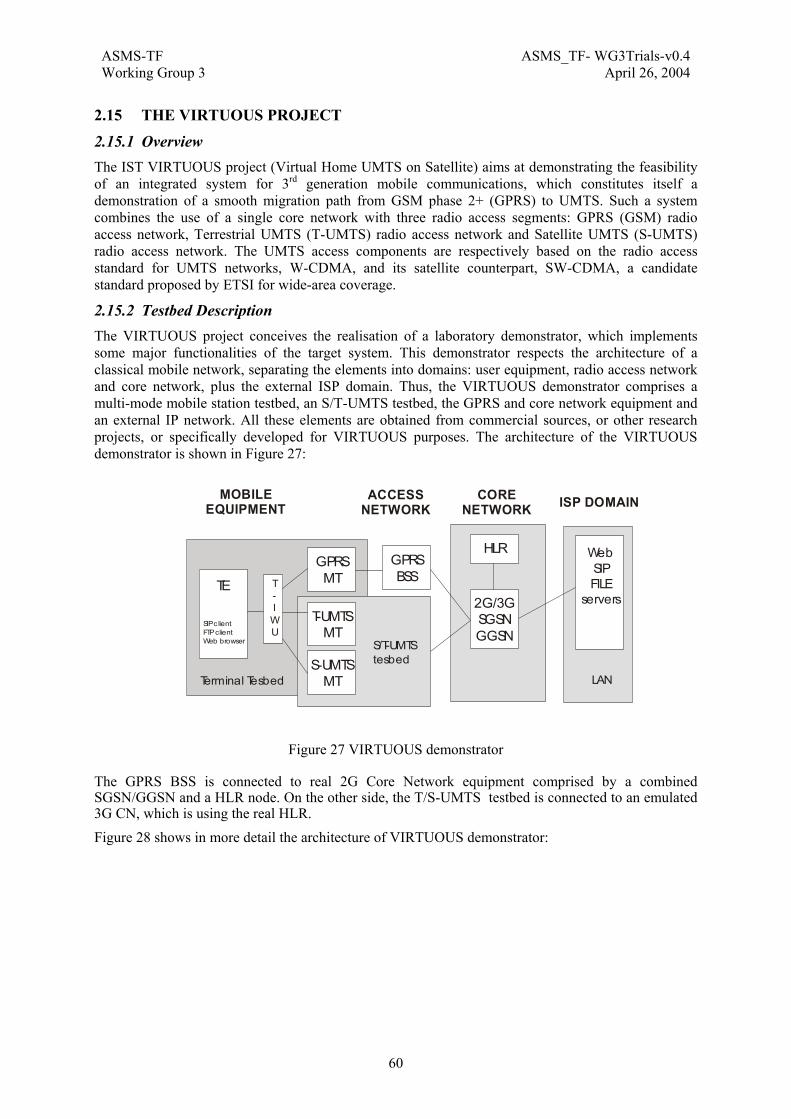
ASMS-TF ASMS_TF- WG3Trials-v0.4Working Group 3 April 26, 2004
60
2.15 THE VIRTUOUS PROJECT
2.15.1 Overview The IST VIRTUOUS project (Virtual Home UMTS on Satellite) aims at demonstrating the feasibility of an integrated system for 3rd generation mobile communications, which constitutes itself a demonstration of a smooth migration path from GSM phase 2+ (GPRS) to UMTS. Such a system combines the use of a single core network with three radio access segments: GPRS (GSM) radio access network, Terrestrial UMTS (T-UMTS) radio access network and Satellite UMTS (S-UMTS) radio access network. The UMTS access components are respectively based on the radio access standard for UMTS networks, W-CDMA, and its satellite counterpart, SW-CDMA, a candidate standard proposed by ETSI for wide-area coverage.
2.15.2 Testbed Description The VIRTUOUS project conceives the realisation of a laboratory demonstrator, which implements some major functionalities of the target system. This demonstrator respects the architecture of a classical mobile network, separating the elements into domains: user equipment, radio access network and core network, plus the external ISP domain. Thus, the VIRTUOUS demonstrator comprises a multi-mode mobile station testbed, an S/T-UMTS testbed, the GPRS and core network equipment and an external IP network. All these elements are obtained from commercial sources, or other research projects, or specifically developed for VIRTUOUS purposes. The architecture of the VIRTUOUS demonstrator is shown in Figure 27:
Figure 27 VIRTUOUS demonstrator
The GPRS BSS is connected to real 2G Core Network equipment comprised by a combined SGSN/GGSN and a HLR node. On the other side, the T/S-UMTS testbed is connected to an emulated 3G CN, which is using the real HLR. Figure 28 shows in more detail the architecture of VIRTUOUS demonstrator:
GPRS MTTE T
-IWU
SIP c lientFTP clientWeb browser
T-UMTSMT
S-UMTSMT
GPRS BSS
WebSIPFILE
servers2G/3GSGSNGGSN
HLR
Terminal Tesbed
S/T-UMTStesbed
LAN
MOBILEEQUIPMENT
CORENETWORK ISP DOMAINACCESS
NETWORK

ASMS-TF ASMS_TF- WG3Trials-v0.4Working Group 3 April 26, 2004
61
T-IWU
S/T-UMTS
MT
MTFA
UEFA
GWFA
BSFA
TBCE
RRC/RANRelay
RRC
TE
S-UMTSPLSE
T-UMTSPLSE
CN-emulator
FTP andWEBserver
SIP-Client
Standard PC
HUB
10/100 BaseEthernet cable
Serial link
GPRS-MT GPRS-BSS 2G
SGSN
2GGGSN
HLR
K1297Classic
192.168.60.2:10590
192.168.60.1:1600
192.168.40.3
192.168.30.3
192.168.40.4:
192.168.30.4:
192.168.70.1:12404
Satellite
Terrestrial
192.168.70.2:
192.168.70.6
Figure 28 Physical VIRTUOUS Demonstrator Architecture
The goals of VIRTUOUS have been achieved and grouped in three experiments: the Inter-segment Roaming experiment, the End-user Service experiment and the QoS experiment. Experimentation on the implemented demonstrator consisted in a set of trials, which produced valuable results in a variety of fields concerning fundamental UMTS concepts. Some of the most important aspects the VIRTUOUS trials studied and exploited are network integration, interoperability and interworking, since the target system envisaged an heterogeneous mobile network that offered seamless connectivity to subscribers irrespective of the radio segment in use or the desired end-user service. This internetworking focused on two areas: mobility across different radio networks and end-to-end transport in a multi-segment environment. The former led to the Inter-segment Roaming experiment, while the latter addressed the End-user Service experiment.
These three experiments produced a significant contribution to the development of the S-UMTS standard in a practical way. The trial design included the execution of the experiments under different scenarios at radio access level. This was achieved by using the physical layer emulators of the VIRTUOUS T/S-UMTS testbed to simulate different propagation delays, multi-path fading, interference effects, etc. for the T-UMTS segment and the equivalent conditions for the satellite constellations in both LEO and GEO configurations for the S-UMTS segment. Thus, the trials demonstrated the effectiveness of S-UMTS technology as an access alternative and the interworking of a satellite system with the terrestrial mobile network.
2.15.3 Demonstration and Trials In the second project period, the activities of mainly comprised functional design, implementation and testing. In this period five main working-parts decided in the previous period, i.e. NAS inter-segment roaming, NAS session management, call control/applications, Iu interface and integration of the specified modules were performed in the following steps:
• Finalisation of the functional design and clear description of functionality: All information from standards and VIRTUOUS were integrated. Functionality adapted to the

ASMS-TF ASMS_TF- WG3Trials-v0.4Working Group 3 April 26, 2004
62
VIRTUOUS demonstrator was clearly described. The explicit standard specification and MSCs were considered by the functionality implementation for VIRTUOUS demonstrator, e.g. integration of each module, method for signal exchange between modules.
• Formal specification (coding) of the NAS functionality: It comprises the programming work on software implementation. Major parts of this activity were specification of Inter-segment roaming, Iu interface and session management.
• Testing: Implemented software were preliminary tested before integration with the other parts coming from the other WPs.
• Analysis/Adaptation of the tools/protocols for the call control and applications. This activity was performed by means of analysis of the application of the SIP protocol and adaptation of software and hardware delivered by SAGO. Description how these tools will be connected to the rest of the VIRTUOUS protocols.
• Integration of the specified modules: This activity includes integration of all software modules of WP700.
The work about CALL CONTROL/APPLICATION activity comprised a design and analysis phase as well as an implementation phase. The functions verification and functional tests were also performed:
• Analysis of the functionality needed for the SIP client Software.
• Re-design of the terminal testbed for the end user experiment which consists now of a Terminal Equipment (TE), a pre-commercial GPRS test mobile station as well as the S/T-UMTS MTs.
• Re-design of the TE and analysis of functionality (connection to GPRS mobile test station as well as S/T-UMTS MTs) of the TE (content of D07.02).
• The relevant VIRTUOUS functions are implemented in the SIP client.
• Implementation of the new functions in the TE partly performed.
• Functional test in the GPRS segment of a FTP and HTTP application with the commercial equipment (2G SGSN/GGSN) were carried out. The test comprises the whole scenario of an application e.g. the start of an application, the triggering of the GPRS test mobile station with AT commands and the usage of the commercial equipment and as peer entities the FTP and the HTTP servers in the LAN (SAGO intranet).
• For the SIP based telephony service a call between the two SIP User Agents were performed to test the relevant VIRTUOUS specific Client functions. This test comprises the test of the principle SIP functionality which are described in the relevant IETF standard and specific tests e.g. the test of support of IP address instead of domain name.
• Finally, a test case with a GPRS test mobile station and a PC located the in LAN was tested. This test was carried out in the a commercial GPRS network environment.
In the management session the design and implementation of the NAS functionality was included to make it possible to establish a connection and exchange data traffic within the E2E Experiment. In the frame of the above the following activities were carried out in detail:
• Definition of the NAS Protocol role in the E2E Experiment.
• Exploitation of the NAS Messages to be used in the frame of the VIRTUOS E2E Experiment.
• Coordination with other experiments in order to build a realistic overall emulation of the terrestrial/satellite communication channel.
ASMS-TF ASMS_TF- WG3Trials-v0.4Working Group 3 April 26, 2004
63
• Architectural Design of the Software implementing the Session Management functions and the minimal Mobility Management functionalities required to make the end to end communication feasible.
• Detailed Design and coding of the identified NAS elements.
• Cooperation with partners in charge of other elements of the protocol to agree interfaces and values to populate the required protocol data structures.
The Inter-segment roaming part includes the design and implementation of the MM functionality with which the network can provide users to be reached irrespective of the access network in an integrated environment. The following activities regarding this functionality were performed in this period:
• Clear definition of the Inter-Segment Roaming and explicit functional design of this procedure
• Research of the required functions supporting this MM functionality
• SDL specification of this MM procedure and the belonging functions
• Converting SDL specification to C++ code which has been decided to be used for the whole integration.
• Integration of modules representing UMTS mobile terminal and UMTS radio access network
The Iu INTERFACE Implementation part concerns the Relay between RRC and RANAP on the network side and the network IWU. The following detailed activities were performed in the scope of this part:
• Definition of the Iu-Interface adapted to VIRTUOUS demonstrator by means of explicit MSC
• Architectural design of the software implementing the Relay procedure between RRC and RANAP
• Detailed design and coding of the identified relay function.
During the last project period, the functions already implemented in the previous project period were tested in terms of correctness of protocols during the pre-integration;
• NAS (SM, MM modules) communication between the RRC in UMTS-MT and URAN (WP 500) and the RRC-RANAP Relay
• Peer-to-peer communication (TE – ISP domain) of the end user experiments (SIP based telephony, ftp, http)
• TE – GPRS MT test to verify the required functions for the end user experiments
In order to enable the Inter-Segment Roaming between T- and S-UMTS in the VIRTUOUS demonstrator, several technical approaches were discussed:
• Manual switching of the protocol tester, K1297
• Usage of two protocol testers
• Implementing CN emulator
• CN Emulator used only for the S/T-UMTS ISR
• CN Emulator used for UMTS Segments (no common HLR)CN Emulator used for UMTS Segments (common HLR)CN Emulator used for GPRS and UMTS SegmentsImplementation

ASMS-TF ASMS_TF- WG3Trials-v0.4Working Group 3 April 26, 2004
64
of CN Emulator with common HLR has been decided because of its effectiveness in implementation time and impacts on other already implemented demonstrator parts. CN Emulator consists of MM, SM, and HLR adaptor interfacing to the real HLR and is intended to be exploited by the FUTURE project.
The CN Emulator was finally implemented and integrated in the VIRTUOUS demonstrator.
2.15.4 Results These are the major points achieved in each phase:
Phase I – Planning and scheduling of trials The overall trial campaign was designed during this period, based upon the work done in WP300 in the past periods and the achievements of other workpackages of the VIRTUOUS projects. The three experiments of VIRTUOUS, InterSegment Roaming, QoS and End-User Service, were defined in WP300. Taking this as input, as well as the current state of the demonstrator implementation and integration efforts, the project developed a trial plan and defined the trial cases for these experiments. The VIRTUOUS trials were defined to exploit the demonstrator capabilities in terms of functionality and performance according to the experiments previously specified. Thus, Deliverable D09.01 (January 2002) was produced to describe the objectives, implementation, general progression, a trial case hierarchy and trial case description for each experiment of VIRTUOUS . The trial case description contained the procedures and features to measure on the demonstrator. The deliverable also included a time schedule for the execution of trials in an effective and date-independent manner, in order to take advantage of the synergy between WP900 and the WP800 Integration Phase. Due to changes in the VIRTUOUS architecture and capabilities regarding the InterSegment Roaming, the deliverable D09.01 was updated. Prior to these modifications in the VIRTUOUS demonstrator, the InterSegment Roaming experiment did not have the ability to perform roaming between T-UMTS segment and S-UMTS segment, due to hardware constraints. The architecture of the demonstrator was reviewed to incorporate this capability and a second edition of D09.01, Deliverable D09.01.02, was issued (April 2002) to reflect these changes and include the corresponding trial cases that were lacking in the previous edition. Phase II – Execution of trials During September 2002, and following the trial specification given in D09.01, the trials were executed on the VIRTUOUS demonstrator. For each experiment, the complete set of test cases was carried out, and all the relevant measurement data was collected for a subsequent exhaustive analysis. Phase III – Interpretation and Critical Assessment of trial results The collected results from the trials were evaluated during the end of the present period (October and November 2002) to elaborate the final conclusions and assessment of the trial campaign. This phase produced Deliverable D09.02 as an outcome, which is was issued in January 2003.
Technical conclusions
InterSegment Roaming experiment
The experiments showed the VIRTUOUS demonstrator's capability to correctly perform a ISR procedure both in manual and in automatic mode. The signalling analysis in the manual mode gave the expected results, and the T-IWU behaviour, compared with the T/S-UMTS physical layers dynamic evolution, was satisfactory also in automatic mode. A quite high switching time has been noticed among segments, and the modifications and improvements to be implemented in an engineering phase have been indicated, in order to solve this problem. As a consequence the ISR experiment can be considered successful.

ASMS-TF ASMS_TF- WG3Trials-v0.4Working Group 3 April 26, 2004
65
QoS experiment
The experiment has shown the efficiency of the QoS algorithm developed in VIRTUOUS. This goal of algorithm, maximising the usage of the overall bandwidth while respecting the QoS constraints, has been proven by a comparison of the VIRTUOUS algorithm to the one recommended by 3GPP and also, by comparing both to a so-called fixed algorithm.
The VIRTUOUS algorithm has proven an equal or better performance than the algorithm proposed by 3GPP. VIRTUOUS QoS scheme adapts to the selected priority for each active data flow and also, adapts to the traffic class of each data flow. For a background class, the VIRTUOUS QoS algorithm minimises mean transfer delay, while for other data source with real-time components (conversational class, streaming) the VIRTUOUS algorithm is much more restrictive with jitter.
End-User Services experiment
In the case of analyses of SIP VoIP connections further data for analyses are of interest. Especially, analyses about the jitter of packages are of interest because this factor has a big impact to voice connections. Additionally it might be of interest to compare the measured parameters of jitter and delay with the corresponding parameters found in the RTP and RTCP protocol.
In case of applications like FTP and HTTP analyses of time critical parts of the protocols could be of interest. At the tests done in VIRTUOUS FTP and HTTP transfers stop in an unexpected manner. This was caused on one hand because of packet loss but on the other hand because of high delays caused by a very bad channel. Such analysis could be of interest in conjunction with the 3GPP standard TS 23.107 where the streaming classes as interactive and background are described. Actually there is no transfer delay defined for these two streaming classes.
Business view of the VIRTUOUS experiments (an operator perspective) In this section, this results are analysed from the business point of view of a mobile operator, bearing in mind the realistic situation of the current mobile market and its evolution towards the consolidation of 3G for both terrestrial and satellite access technologies.
InterSegment Roaming experiment
Towards the provision of a seamless service
European operators have deployed the UMTS networks only to meet legal or government requirements. However, it is clear that 3G technology is not mature enough for commercial exploitation yet, mainly due to the instability of the 3GPP standards. 3GPP Release 99 specifications are considered functionally frozen since early 2000, but there are still continuous changes to the standards to correct interoperability issues or technical minor problems, reflecting the complexity of a technology which is far from being consolidated. On the other hand, the fact that there are no WCDMA commercial terminals available yet and there are none expected until next year. This means that the WCDMA Node B stations are radiating and the service is being provided while there is no chance for a user to be accessing the UMTS network.
Due to this prevision, and a logical deployment strategy, mobile operators are only providing wireless coverage in certain focused urban sites. Investments must be reimbursed prior to enlarge coverage. This all leads to a tight dependency of the 2.5G network to guarantee the operator service for every subscriber everywhere. This conclusion is supported by the fact that most GSM-licensed operators in Europe were also granted a 3G license.
For a seamless 2G-3G combined services (including satellite services) a mobility solution must be implemented. This solution must allow the roaming among different radio technologies (both GSM and UMTS, both terrestrial and satellite). However, the interworking and duality between GSM and UMTS networks for a seamless roaming/handover is not implemented in the current operator network. The UMTS standards on this issue are not completely specified or don’t give a clear solution for the actually deployed 3G network (which follows 3GPP Release 99 standards).

ASMS-TF ASMS_TF- WG3Trials-v0.4Working Group 3 April 26, 2004
66
An operator directive, as well as other industrial parties, regarding brand-new technologies is to experiment them first on demonstrators and testbeds before implementing them in the testing network, since this allows to detect errors and potential improvements only visible in practice. The InterSegment Roaming experiment gives results on this critical issue for data communication seamless service provision with GPRS, Terrestrial and Satellite UMTS. ISR focuses on the packet-switched domain, but this is not a handicap, rather this fits the operator strategy to promote the mobile data market with the recent launching of the commercial services based on IP technologies: Multimedia Messaging Service and the 2.5G GPRS exploitation.
The conclusion is that the InterSegment Roaming experiment gives satisfactory functional results in the field of mobility and backwards compatibility. The InterSegment Roaming is an encouraging solution for laboratories and technology certification departments in operator organisations. The foreseen next steps would be optimisation and to obtain a better performance for a pre-commercial functionality.
Integration of satellite data communications into the 3G service
Operators are not very confident with satellite communications, since previous commercial initiatives of satellite systems as an alternative for mobile communications were a disaster. An example would be Iridium, which went into bankruptcy some months after its launching in 1999.
For a feasible approach, data communications on satellite should be integrated into a global system, not an independent component. This is the S-UMTS role in 3G, as well as in the VIRTUOUS project.
Another feasible approach would be to minimise the imbursement by making use of satellite constellations that are originally intended for other main purposes aside data communications. For example, navigation satellite systems could support a low-rate data bearer, as it was considered for the Galileo system.
In any case, these trends in the satellite field would also lead to the necessity of implementing a mobility solution between terrestrial and satellite components, in order to provide seamless services to the T/S-combined users and to promote satellite services for terrestrial-only subscribers.
The conclusion is that the InterSegment Roaming functionality as implemented in VIRTUOUS provides both a demonstration and a feasible solution for mobility in heterogeneous access segments.
QoS experiment
The assurance of Quality of Service is of paramount importance for the services an operator is planning to provide by means of the 3G network. Multimedia services and contents is the bet that operators have in mind to overcome the recent crisis noticed in the mobile market. It is clear that for multimedia mobile services, the QoS must be assured in an efficient way, in order to fulfill subscribers expectations and to make a fair use of operator resources. However, customers are used to the multimedia as delivered by fixed access technologies (such as xDSL or HFC networks). The problem is that the mobile broadband will never offer as much bandwidth as the fixed broadband technologies. For that reason, an efficient QoS scheme in mobile 3G can maximize the use of bandwidth and provide a fair user experience.
The QoS experiment in VIRTUOUS has proven to make an efficient use of communications resources. Besides, the QoS algorithm has proven to perform better that the recommended by 3GPP, as the technical results show in this deliverable.
The final conclusion is that operators and vendors should consider also innovative solutions such as the ones implemented in VIRTUOUS and not only those proposed by standardization fora as the only possible techniques.
End-User Services experiment
Anticipating the future mobile ALL-IP services
End-User Services experiment gives a demonstration on end-to-end connectivity following the standard procedures. However, the most attractive part of this experiment from an operator’s point of

ASMS-TF ASMS_TF- WG3Trials-v0.4Working Group 3 April 26, 2004
67
view would be the SIP VoIP trials over the UMTS segments. These trials provide information about performance of real-time multimedia IP in mobile environments.
The ALL-IP trends in standardization bodies are addressing evolution strategies for the operator recently-deployed 3G network. The operator evolution now is focusing on the 3GPP IP Multimedia Subsystem (also present 3GPP2 CDMA2002 architecture). The IP Multimedia Subsystem offers the operator an infrastructure for the provision of multimedia services based on the packet-switched domain (the GPRS service). This infrastructure allows the provision of both legacy traditional services (like voice calls) and also, innovative rich applications based on IP Multimedia.
Currently, operators are making efforts in analyzing IMS and studying the impacts of IP Multimedia in the 3G network. A migration path from 3GPP Release 99 networks to the Release 5 must be considered. Taking this into account, a feasible approach is to use demonstrators to evaluate issues which are only visible in practice. The VIRTUOUS demonstrator is an example of this.
In this sense, the VIRTUOUS End-User experiment provides results in advance of future trends.

ASMS-TF ASMS_TF- WG3Trials-v0.4Working Group 3 April 26, 2004
68
2.16 THE WIRELESSCABIN PROJECT WirelessCabin is an EC Project (IST-2001-37466) made up of the following partners: DLR, Airbus, Ericsson, ESYS, Inmarsat, KID-Systeme, Siemens Austria, TriaGnoSys and University of Bradford. Information on the project and the consortia can be found under www.wirelesscabin.com.
2.16.1 Overview The WirelessCabin project is developing wireless access technologies for aircraft cabins. Several access technologies in the cabin are envisaged for passengers: UMTS for personal telephony and packet data, Bluetooth and W-LAN for IP access. The Bluetooth interface will also be used for transport of UMTS services.
The project will define a system architecture for wireless access (UMTS, W-LAN and Bluetooth) in an aircraft cabin. The passenger will have the possibility to use its own personal equipment (mobile phone, laptop). For this, the project will develop a service integrator that maps the cabin services on a satellite bearer to be connected to the terrestrial infrastructure.
The concept of the wireless cabin access will be demonstrated in flight via satellite using an Airbus long-haul aircraft. The cabin services will provide mobility, VPNs and AAA functions which need to be developed for the mobile users.
2.16.2 Testbed Description The testbed will consist, on the aircraft side, mainly of the different access nodes (W-LAN, UMTS and Bluetooth), the service integrator and a IP Server plus the satellite modems and the antenna. For the ground segment the integration with a UMTS network controller and the Mobility IP server on ground will be demonstrated.
Satellite
Satellite dish
ModemBank
Sat-Modem
Multiplexer
Terrestrial telecom router
Laptop computer
Laptop computer
Laptop computer
Laptop computer
Satellite dish
ModemBank
Multiplexer
IPBackbone
PSTNUMTSGSM
Bluetooth
Multiplexer
Service IntegratorService Integrator
Passenger’sCompanyIntranet
AAA, BillingMobility ISP serverVPN, mobility support,QoS support
Aircraft Protocol FunctionsIP mobility Server
AAAVPNDHCPQoS
Cabin Segment
Ground Segment
Space Segment
Service IntegratorService IntegratorW-LAN
GMSC
SGSN GGSN
MSC
UMTS
Aircom Provider Segment
UMTSUMTS CoreCore
UMTS
LAN
Bluetooth
BluetoothUMTS
Laptop computer
Laptop computer
LAN
RNC
Figure 29 WirelessCabin test bed architecture
2.16.3 Demonstration and Trials On ground and in-flight demonstration with an Airbus A340 are planned. The inflight demo is scheduled for March 2004 and will show different services, ranging from telephony, videoconference
ASMS-TF ASMS_TF- WG3Trials-v0.4Working Group 3 April 26, 2004
69
to web browsing and intranet access for business applications, including authentication, authorisation and accounting functionality.
2.16.4 Results
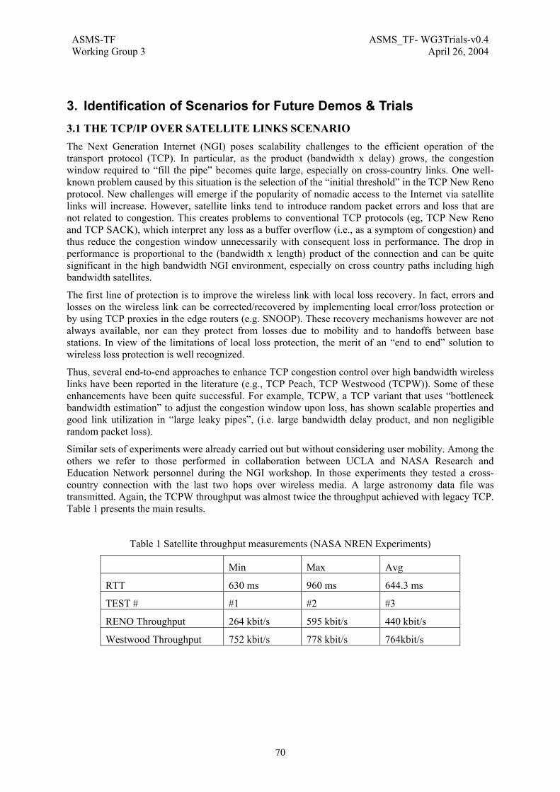
ASMS-TF ASMS_TF- WG3Trials-v0.4Working Group 3 April 26, 2004
70
3. Identification of Scenarios for Future Demos & Trials 3.1 THE TCP/IP OVER SATELLITE LINKS SCENARIO The Next Generation Internet (NGI) poses scalability challenges to the efficient operation of the transport protocol (TCP). In particular, as the product (bandwidth x delay) grows, the congestion window required to “fill the pipe” becomes quite large, especially on cross-country links. One well-known problem caused by this situation is the selection of the “initial threshold” in the TCP New Reno protocol. New challenges will emerge if the popularity of nomadic access to the Internet via satellite links will increase. However, satellite links tend to introduce random packet errors and loss that are not related to congestion. This creates problems to conventional TCP protocols (eg, TCP New Reno and TCP SACK), which interpret any loss as a buffer overflow (i.e., as a symptom of congestion) and thus reduce the congestion window unnecessarily with consequent loss in performance. The drop in performance is proportional to the (bandwidth x length) product of the connection and can be quite significant in the high bandwidth NGI environment, especially on cross country paths including high bandwidth satellites.
The first line of protection is to improve the wireless link with local loss recovery. In fact, errors and losses on the wireless link can be corrected/recovered by implementing local error/loss protection or by using TCP proxies in the edge routers (e.g. SNOOP). These recovery mechanisms however are not always available, nor can they protect from losses due to mobility and to handoffs between base stations. In view of the limitations of local loss protection, the merit of an “end to end” solution to wireless loss protection is well recognized.
Thus, several end-to-end approaches to enhance TCP congestion control over high bandwidth wireless links have been reported in the literature (e.g., TCP Peach, TCP Westwood (TCPW)). Some of these enhancements have been quite successful. For example, TCPW, a TCP variant that uses “bottleneck bandwidth estimation” to adjust the congestion window upon loss, has shown scalable properties and good link utilization in “large leaky pipes”, (i.e. large bandwidth delay product, and non negligible random packet loss).
Similar sets of experiments were already carried out but without considering user mobility. Among the others we refer to those performed in collaboration between UCLA and NASA Research and Education Network personnel during the NGI workshop. In those experiments they tested a cross-country connection with the last two hops over wireless media. A large astronomy data file was transmitted. Again, the TCPW throughput was almost twice the throughput achieved with legacy TCP. Table 1 presents the main results.
Table 1 Satellite throughput measurements (NASA NREN Experiments)
Min Max Avg
RTT 630 ms 960 ms 644.3 ms
TEST # #1 #2 #3
RENO Throughput 264 kbit/s 595 kbit/s 440 kbit/s
Westwood Throughput 752 kbit/s 778 kbit/s 764kbit/s
ASMS-TF ASMS_TF- WG3Trials-v0.4Working Group 3 April 26, 2004
71
3.1.1 Objectives Given:
1. The increasing importance of nomadic computing and wireless access to the high speed wired Internet
2. The performance degradations observed in conventional TCP protocols over wireless path
3. The encouraging improvements offered by modified, “wireless” versions of TCP (which yet retain the basic end to end paradigm)
it is believed that this a very appropriate time to engage in a systematic, experimentally based evaluation of “wireless” TCP protocols by a team that includes protocol developers, applications developers and network measurement experts.
The proposal is about carrying out a systematic, experimental investigation of performance of TCP over satellite paths. This investigation will include the comparison of various TCP enhancements proposed so far in the literature. It will consider a representative set of experimental environments and application scenarios. In our project we intend to evaluate a vast gamut of TCP wireless enhancement techniques in the attempt to identify the pros and cons of each scheme, to characterize the traffic/network environment for which it is best suited, and, more generally, to develop a model that relates wireless media characteristics, TCP congestion control parameters and performance results.
3.1.2 Description In our study we intend to carry out a more systematic investigation of available alternatives, characterizing the behaviour and performance of TCP.
We will carry out most of our tests in an Internet 2 environment that may include a broad range of wireless links (satellites, cellular radio networks and wireless LANs). We will define several performance measures against which the alternative will be compared. We will develop a representative set of test scenarios, including existing high performance applications that have been generated for an Internet 2 environment. The Internet 2 testing will be done jointly with the collaborators that created such applications. This will give us the opportunity to evaluate the impact of TCP protocol improvements not only using the conventional performance measures (delay, throughput, etc) but also via end user perceived satisfaction.
We will devote particular attention to the instrumentation and control of our experiments. For example, our experiments will be monitored with specialized network measurement tools. Some of the tools will be used to evaluate TCP and applications end-to-end performance. Other tools will allow us to monitor the network conditions during the experiment. The combination of TCP and network measurements will allow us:
• To evaluate the ability of a particular transport protocol to react to different network conditions;
• To determine the causes of possible inefficiencies and;
• To fine-tune the protocol parameters.
A key performance measure will be “friendliness”; i.e., the ability of the newly proposed protocols to coexist harmoniously with legacy TCP and streaming protocols.
We will be considering different types of applications, all involving the delivery of medium to large files (generally, with latency constraints) over a wide area. These applications will stress the TCP protocols in different ways and will help compose a broad and rich traffic scenario. Among the considered applications there will be FTP and http.
3.1.3 Expected Results The expected outcomes of the set of experiments will be:
1. A methodology and a benchmark for the evaluation of transport protocols. This benchmark will include tools specifically developed in this project,
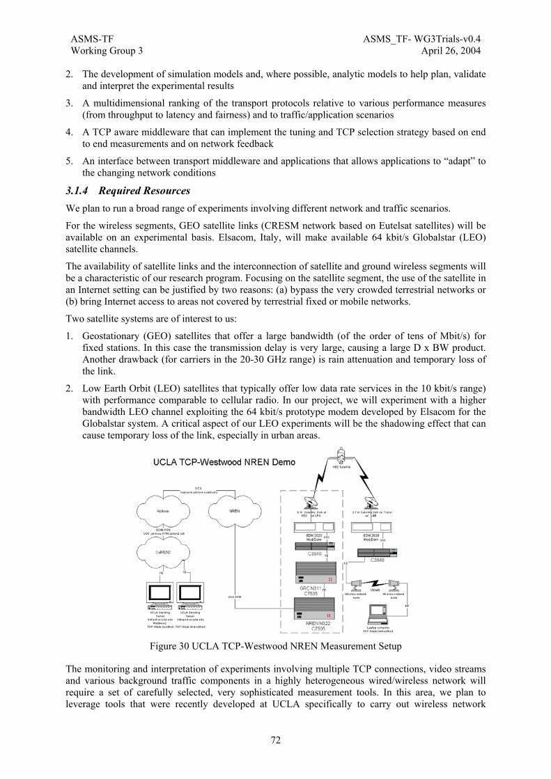
ASMS-TF ASMS_TF- WG3Trials-v0.4Working Group 3 April 26, 2004
72
2. The development of simulation models and, where possible, analytic models to help plan, validate and interpret the experimental results
3. A multidimensional ranking of the transport protocols relative to various performance measures (from throughput to latency and fairness) and to traffic/application scenarios
4. A TCP aware middleware that can implement the tuning and TCP selection strategy based on end to end measurements and on network feedback
5. An interface between transport middleware and applications that allows applications to “adapt” to the changing network conditions
3.1.4 Required Resources We plan to run a broad range of experiments involving different network and traffic scenarios.
For the wireless segments, GEO satellite links (CRESM network based on Eutelsat satellites) will be available on an experimental basis. Elsacom, Italy, will make available 64 kbit/s Globalstar (LEO) satellite channels.
The availability of satellite links and the interconnection of satellite and ground wireless segments will be a characteristic of our research program. Focusing on the satellite segment, the use of the satellite in an Internet setting can be justified by two reasons: (a) bypass the very crowded terrestrial networks or (b) bring Internet access to areas not covered by terrestrial fixed or mobile networks.
Two satellite systems are of interest to us:
1. Geostationary (GEO) satellites that offer a large bandwidth (of the order of tens of Mbit/s) for fixed stations. In this case the transmission delay is very large, causing a large D x BW product. Another drawback (for carriers in the 20-30 GHz range) is rain attenuation and temporary loss of the link.
2. Low Earth Orbit (LEO) satellites that typically offer low data rate services in the 10 kbit/s range) with performance comparable to cellular radio. In our project, we will experiment with a higher bandwidth LEO channel exploiting the 64 kbit/s prototype modem developed by Elsacom for the Globalstar system. A critical aspect of our LEO experiments will be the shadowing effect that can cause temporary loss of the link, especially in urban areas.
Figure 30 UCLA TCP-Westwood NREN Measurement Setup
The monitoring and interpretation of experiments involving multiple TCP connections, video streams and various background traffic components in a highly heterogeneous wired/wireless network will require a set of carefully selected, very sophisticated measurement tools. In this area, we plan to leverage tools that were recently developed at UCLA specifically to carry out wireless network

ASMS-TF ASMS_TF- WG3Trials-v0.4Working Group 3 April 26, 2004
73
measurements. As far as software simulators are concerned the use of ns-2 will be highly considered. Finally, we will use simulation and (when available) analytic models to validate and interpret the measurements.
As far as hardware equipments is needed in Figure 30 a possible architecture is reported.

ASMS-TF ASMS_TF- WG3Trials-v0.4Working Group 3 April 26, 2004
74
4. Conclusions In this report a survey of existing EC and ESA projects relevant to ASMS was carried out. The main focus was on the testbed configurations that were used by each project, the demonstrations and trials that were conducted (or were planned to be conducted), and an overview of the available results, if any.
The next stage will be to discuss possible synergies among these projects and testbed configurations, and the nature and scope of potential follow-on projects. The results of the work will be reviewed in order to define a family of projects, based on specific ASMS architectures (e.g. S-DMB, S-UMTS).
ASMS-TF ASMS_TF- WG3Trials-v0.4Working Group 3 April 26, 2004
75
5. References [DMB, 1] M.G. Francon, “Satellite-based multicast layer for 3G mobile networks”, EMPS
2002, September, 2002
[MOD, 2] M. Mazzella, N. Chuberre, O. Courseille and C. Nussli, “MoDiS: S-DMB experimental platform”, EMPS 2002, September, 2002
[ROB, 3] Architecture And Design Of The “Robmod” Test Bed, A Comprehensive Facility For S-UMTS Air Interface Validation, by C. Campa, G. Chiassarini, R. De Gaudenzi, P. Eglin, B. Kull, N. Schmidt, L. Veltri, A. Vernucci and H. Widmer, presented at DSP 2001, 7th International Workshop on Digital Signal Processing Techniques for Space Communications, Lisbon, 1-3 October 2001.
[ATB, 4] C. Aroud, R. De Gaudenzi, G. Gallinaro, C. Iannone, M. Reed and A. Vernucci, “Laboratory And On-The-Air Trials Of An S-UMTS Approach Supporting Packet Access And Multicasting: The ESA Advanced Test Bed Project”, EMPS 2002, September 2002.
[SUI, 5] Ray E. Sheriff et alt., Space/Terrestrial Mobile Networks, John Wiley & Sons 2004

ASMS-TF ASMS_TF- WG3Trials-v0.4Working Group 3 April 26, 2004
76
6. Acronyms and Abbreviations ASMS-TF Task Force on Advanced Satellite Mobile Systems
S-DMB Satellite Digital Multimedia Broadcasting