report 1: concepts/structural conditions report smilow
TRANSCRIPT

Technical Report 1: Structural Concepts/Structural Existing Conditions Report
SMILOW CANCER CENTER – YALE‐NEW HAVEN HOSPITAL
20 York Street, New Haven, Connecticut
Pennsylvania State University
Department of Architectural Engineering
Dan Navarrete – Structural Option
Consultant: Dr. Ali Memari
29 September 2008
http://www.engr.psu.edu/ae/thesis/portfolios/2009/don5000

http://www.engr.psu.edu/ae/thesis/portfolios/2009/don5000
Executive Summary ii.
Smilow Cancer Center: Overview iv. ral System
- Summary ns
abs + Beams 3 Lateral Resisting System
v. ign Loads Gravity Loads
a. Wind Load Calculations
Load Calculations vi. er Spot‐Checks vii.
Appendix
Sketches of Shear Wall Sections oad Hand Calculations/Sketches
Wind Load Pressure Diagrams Load Hand Calculations Load Story Shear Diagram
- d Calculations)
TABLE of CONTENTS
i. 1 Introduction 1
iii. 2 Structu
2 - Foundation + Colum 3 - Floor Sl- 4
Building Des- 6 - Lateral Loads 7
7 b. Seismic 12
Memb 16 Conclusion 16
viii. - List of Figures & Tables A0 - A1 - Wind L A2- A4 - Seismic A6 - Seismic A7
Member Spot‐Checks (Han A8
Pennsylvania State University Smilow Cancer Center Department of Architectural Engineering New Haven, Connecticut Dan Navarrete – Structural Option Technical Report 1 Consultant: Dr. Ali Memari 29 September 2008
al system.
Technical Report 1: Structural Concepts/Structural Existing Conditions Report SMILOW CANCER CENTER — YALE‐NEW HAVEN HOSPITAL 20 York Street, New Haven, Connecticut
EXECUTIVE SUMMARY After going through and determining certain types of lateral loads and quickly checking typical member sizes, it is evident that the designers of the Smilow Cancer Center were under a different set of restrictions when deciding on what type and size of members to use. From the member spot‐checks done on a representative bay, it is obvious that gravity loading was not the controlling limit state for beam and column sizes. Some of the beams had capacities up to six times the factored load. One possible explanation is that lateral load was the controlling factor, or perhaps the structural engineer was under stricter limitations regarding the amount of tolerable deflection or vibration in the building. The space is, after all, a hospital where sensitive equipment operates and important surgical procedures take place. Also, the set of assumptions made by the student in calculating gravity and lateral loads may have somewhat skewed the results, leading to discrepancies in member sizes. For example, in assuming the building footprint continues on as a rectangle past the fifth floor, the calculation of wind loads becomes much simpler. But, at the same time, that assumption neglects the significant effects of having horizontal as well as vertical irregularities in the building. And finally, another possible cause for the variation in the loads calculated is the different set of codes used by the structural engineer and the student. The Connecticut State Building Code, the one used by the designer, is inherently much more specific to the region than the national ASCE Standard. Consequently, the state code would be more accurate in describing conditions around that area, whereas the national standard would be broader in scope and more general. Ultimately, the purpose of this report was for the student to become more familiar with the structure of the building. With a more intimate knowledge of the existing structure, the student can begin to develop ideas about an alternative structur INTRODUCTION The Structural Concepts/Structural Existing Conditions Report (Tech Report 1) is an overview of the current design for the Smilow Cancer Center in New Haven, CT. As a preliminary study of the building, Tech Report 1 contains a general description of the hospital’s structural system. Two of the major lateral loads on the structure—wind and seismic—are calculated according to the 2005 version of the American Society of Civil Engineers (ASCE) Standard for Minimum Design Loads for Buildings and Other Structures. The calculated values are then compared with any available load information from the construction documents. Also, a simplified spot‐check for typical structural members is included in the report; note that this check considers only gravity loads as a limit state.
1 http://www.engr.psu.edu/ae/thesis/portfolios/2009/don5000

Pennsylvania State University Smilow Cancer Center Department of Architectural Engineering New Haven, Connecticut Dan Navarrete – Structural Option Technical Report 1 Consultant: Dr. Ali Memari 29 September 2008 SMILOW CANCER CENTER: Overview of Architecture, Project Information, and Code Analysis Located in the middle of New Haven, the addition of the Smilow Cancer Hospital to the Yale‐New Haven Hospital complex will feature a state‐of‐the‐art building with the latest equipment for the treatment of the disease. The several areas of specialization are separated among the sixteen stories of the building, with the larger equipment (i.e. MRIs, ultrasound, operating rooms) housed primarily on the lower floors and the 112 inpatient rooms—all single rooms—starting on the eleventh floor. As for the exterior, the façade emulates that of the surrounding buildings in the complex with its glass and terra cotta curtain walls. For ease of installation, a unitized curtain wall panel system was used: the glass and terra cotta come in pre‐installed panels ready to be attached to the structure. The hospital’s roof is a combination of cast‐in‐place concrete roof deck and metal (steel) decking. The insulation and waterproofing are comprised of fully adhered thermoplastic polyolefin (TPO) sheet membrane roofing over mechanically attached insulation and cover board. Construction on the 497,000 square foot project began in September of 2006 and is projected to be completed by early 2009. Overall cost is estimated at about $253 million. The architect is Shepley Bulfinch Richardson & Abbott of Boston, and Turner Construction Company is the construction manager [see “Building Statistics Part 1 for a full list of the primary project team]. Structural design was headed by Spiegel Zamecnik & Shah of New Haven, CT. The design of the building follows the 1999 Connecticut State Building Code which adopts mostly from “The BOCA National Building Code/1996.” Other codes and standards used in the design of the structure are listed below:
- ASCE 7‐02: Load combinations for consideration of future vertical expansion - ACI 318‐02: “Building Code Requirements for Structural Concrete” - ACI 315‐latest edition: “Details and Detailing of Concrete Reinforcement” - AISC LRFD Steel Manual (2nd Edition): “LRFD Specification for Structural Steel Buildings” - AISC 341‐02: Seismic Provisions for Structural Steel Buildings - Latest Specifications of the Steel Deck Institute - “Specification for Welded Steel Wire Fabric for Concrete Reinforcement” (Latest Edition)
by the Wire Reinforcement Institute The hospital’s structure and curtain walls were designed for wind loads using the Main Wind Force Resisting System (MWFRS) method and Components and Cladding (C&C) method as prepared by RWDI, Inc. of Guelph, Ontario. As for seismic loads, the structural engineer used the Equivalent Lateral Force Procedure (ELFP). STRUCTURAL SYSTEM: Summary The structural system of Smilow Cancer Center consists of a concrete slab on metal deck floor system supported on a steel framing system (moment, lateral braced, and regular gravity frames) and four reinforced concrete (RC) shear walls. On the first level, concrete beams of varying sizes run along three edges of the building. The floor slab and steel beams act in composite action with each other, while the moment frames and shear walls share the lateral load. The whole structure rests on a 4‐foot thick mat slab foundation (the slab is 8 feet thick at shear wall locations). A relatively simple structure, the footprint of the building through the first five levels is almost square (210 ft. x 176 ft.). At the beginning
2 http://www.engr.psu.edu/ae/thesis/portfolios/2009/don5000

Pennsylvania State University Smilow Cancer Center Department of Architectural Engineering New Haven, Connecticut Dan Navarrete – Structural Option Technical Report 1 Consultant: Dr. Ali Memari 29 September 2008
of the seventh floor1, however, the northeast “corner” of the building ends in a rooftop garden, and the rest of the building rises to the roof as an L‐shape. Normal weight concrete is used for the shear walls and the foundation, while lightweight concrete is used for the floor slabs. Concrete strength ranges from 3000 psi to 8000 psi depending on the location and use. All reinforcement is A615 Grade 60 steel. A range of steel W‐shapes are used for the framing system, but all are of the standard A992 grade steel (Fy = 50 ksi). Additionally, Hollow Structural Shapes (HSS) conform to ASTM A500 Grade B, while all other steel shapes (i.e. plates, channels, etc.) conform to ASTM A36 (Fy = 36 ksi). STRUCTURAL SYSTEM: Foundation + Columns
Figure 1: BP‐7 Column Base Plate Detail
As mentioned above, the foundation for Smilow Cancer Center is a 4‐foot thick mat slab with different types of column base plates down at the basement level. These columns vary from W‐shapes, HSS, and even cruciform columns consisting of a wide flange plus two T‐shapes2—all of which are encased in concrete. Some columns are regular reinforced concrete columns. Starting on the first floor, the columns continue up the structure as regular steel columns. STRUCTURAL SYSTEM: Floor Slabs + Beams The typical floor slab for Smilow Cancer Center is a 4‐1/2” thick lightweight concrete slab on a 3” deep, galvanized, 18 gage composite steel floor deck with a 3 span minimum. Reinforcement consists of one layer of 6 x 6 – D4 x D4 welded bar mesh and top reinforcing bars. The slab is supported on steel framing and concrete shear walls at some locations. As per ASCE 05, the floor slabs are considered as rigid diaphragms when taking into account lateral loads. The hospital’s typical bay3 is a 30 ft. x 30 ft. square with W‐shape columns at the corners, W24 girders along the perimeter, and two W18/21/24 beams spaced evenly at 10 ft. on‐center. As discussed in the following section, most of the beams frame into simple gravity columns, while moment frames and shear walls are dispersed throughout the structure to effectively resist lateral loads.
1 Smilow Cancer Center does not have floors labeled 6th or 13th for superstition purposes. 2 See Figure 1: BP‐7 Plan Detail. 3 See Figure 2: Typical Bay Plan.
3 http://www.engr.psu.edu/ae/thesis/portfolios/2009/don5000

Pennsylvania State University Smilow Cancer Center Department of Architectural Engineering New Haven, Connecticut Dan Navarrete – Structural Option Technical Report 1 Consultant: ember 2008
4 http://www.engr.psu.edu/ae/thesis/portfolios/2009/don5000
Dr. Ali Memari 29 Sept
Figure 2: Typical Bay Plan – The typical 30’x30’ bay is shown here highlighted in green.
STRUCTURAL SYSTEM: Lateral Resisting System Smilow Cancer Center’s lateral resisting system is a combination of six primary moment frames, several smaller lateral braced frames on the roof, and four C‐shaped RC shear walls. Four of the six main moment frames are located at the edges of the building, while the remaining two run along the east‐west direction at approximately one‐third points of the building’s length4. The four shear walls are all located towards the southeast quadrant of the building, strategically placed around central elevator and mechanical openings. All four shear walls rise up to either the sixteenth or seventeenth floor, ending where the lateral braced frames of the roof begin. Refer to page A1 of the Appendix for sketches of the shear wall sections.
4 See Figures 3a & 3b: Moment Frame Locations.

Pennsylvania State University Smilow Cancer Center Department of Architectural Engineering New Haven, Connecticut Dan Navarrete – Structural Option Technical Report 1
5 http://www.engr.psu.edu/ae/thesis/portfolios/2009/don5000
Consultant: Dr. Ali Memari 29 September 2008
Figure 3a: Typical Framing Plan for Levels 1‐5. Green denotes Moment Frames; Red denotes Shear Walls.

Pennsylvania State University Smilow Cancer Center Department of Architectural Engineering New Haven, Connecticut Dan Navarrete – Structural Option Technical Report 1
6 http://www.engr.psu.edu/ae/thesis/portfolios/2009/don5000
Consultant: Dr. Ali Memari 29 September 2008
Figure 4: Typical Framing Plan for Levels 7‐17. Green denotes Moment Frames; Red denotes Shear Walls.
BUILDING DESIGN LOADS: Gravity Loads For the student’s preliminary calculations, gravity loads were determined as per ASCE 7‐05, 13th Edition of the AISC Steel Manual, other relevant publications, and a few assumptions on the student’s part. Construction documents (CD) also provided some insight into code compliant loads. Table 1 below summarizes loads by type and material. Table 1: Gravity Loads FLOOR LOADS
Type Material/Occupancy Load Reference
Dead Load
Normal Weight Concrete
145 pcf [Assumed]
Light Weight Concrete 110 pcf [Assumed] Steel per shape AISC 13th Edition
Partitions 20 psf [Assumed] Superimposed 10 psf CD: S605 – S606
Common Areas 100 psf CD: S605 – S606

Pennsylvania State University Smilow Cancer Center Department of Architectural Engineering New Haven, Connecticut Dan Navarrete – Structural Option Technical Report 1 Consultant: Dr. Ali Memari 29 September 2008
Live Load
Lobbies 100 psf CD: S605 – S606 Corridors (1F) 100 psf ASCE 7‐05
Corridors (Above 1F) 80 psf ASCE 7‐05 Operating Rooms 80 psf CD: S605 – S606 Exam Rooms 80 psf CD: S605 – S606 Mechanical 150 psf CD: S605 – S606
Stairs 100 psf CD: S605 – S606 ROOF LOADS
Dead Load
Normal Weight Concrete
145 pcf [Assumed]
Light Weight Concrete 110 pcf [Assumed] Steel per shape AISC 13th Edition
Superimposed 25 psf CD: S605 – S606 Live Load Roof Live Load 33 PSF CD: S605 – S606
Note: Snow and rain loads were not a requirement for Tech Report 1 and as such were not included in the load calculations. BUILDING DESIGN LOADS: Lateral Loads As per ASCE 7‐08, lateral loads—specifically wind and seismic—were calculated to compare against design loads used by the structural engineer. The methods used for calculating wind and seismic loads were the Main Wind Force Resisting System (MWFRS) and the Equivalent Lateral Force Procedure (ELFP), respectively. Other references include IBC 2006 and the United States Geological Service website, usgs.gov. Refer to the following spreadsheets for a summary of wind and seismic load calculations. Also, pressure (wind) and story shear (seismic) diagrams are included in pages A4‐A7 of the Appendix. WIND LOAD CALCULATIONS Basic Wind Speed (mph) V= 120
Fig. 6‐1
Wind Directionality Factor Kd=
0.85
Table 6‐4
Occupancy Category, IBC IV
Importance Factor I= 1.15
Table 6‐1
Exposure Category EC= B
6.5.6
7 http://www.engr.psu.edu/ae/thesis/portfolios/2009/don5000

Pennsylvania State University Smilow Cancer Center Department of Architectural Engineering New Haven, Connecticut Dan Navarrete – Structural Option Technical Report 1 Consultant: Dr. Ali Memari 29 September 2008
Topographic Factor Kzt= 1
6.5.7.1
Velocity Coefficient Kz [see table] Table 6‐3
Velocity Pressure qz [see table]
Eq. 6‐15
Building Frequency n1= 0.282 <1 C6‐15 (Steel MRF) (flexible)
Peak Factors gQ=gv= 3.4
6.5.8.2
Peak Factor gR= 3.88
Eq. 6‐9
Turbulence Factor z= 141 > zmin = 30' 6.5.8.1
Intensity of Turbulence Iz= 0.236 c = 0.3
Eq. 6‐5 Table 6‐2
Integral Length Lz= 519 l = 320' Є =1/3.0
Eq. 6‐7 TABLE 6‐2
TABLE 6‐2
Background Response Q= 0.806
Eq. 6‐6
Mean Wind Speed Vz= 113.9 α = 0.25 b = 0.45
Eq. 6‐14 TABLE 6‐2
TABLE 6‐2
8 http://www.engr.psu.edu/ae/thesis/portfolios/2009/don5000

Pennsylvania State University Smilow Cancer Center Department of Architectural Engineering New Haven, Connecticut Dan Navarrete – Structural Option Technical Report 1 Consultant: Dr. Ali Memari 29 September 2008 Reduced Frequency N= 1.28
Eq. 6‐12
Eq. 6‐11 Rn= 0.115
Eq. 6‐13 Rh= 0.305 η= 2.67
Eq. 6‐13 RB= 0.386 η= 1.93
Eq. 6‐13 RL= 0.116 η= 8.11
Resonant Response R(N‐S)= 0.089 β= 1
Eq. 6‐10 R(E‐W)= 0.054
Gust Effect Factor Gf= 0.83 (N‐S)
Eq. 6‐8 Gf= 0.82 (E‐W)
ENCLOSED? YES
LOW‐RISE? YES
RIGID? NO
External Pressure Coefficients (Fig. 6‐6)
Windward Cp= 0.8
Leeward (N‐S) Cp= ‐0.45 L/B= 1.25
Leeward (E‐W) Cp= ‐0.5 L/B= 0.80
9 http://www.engr.psu.edu/ae/thesis/portfolios/2009/don5000
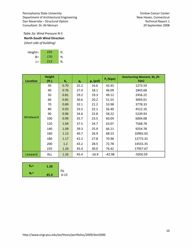
Pennsylvania State University Smilow Cancer Center Department of Architectural Engineering New Haven, Connecticut Dan Navarrete – Structural Option Technical Report 1 Consultant: Dr. Ali Memari 29 September 2008 Table 2a: Wind Pressure N‐S North‐South Wind Direction (short side of building)
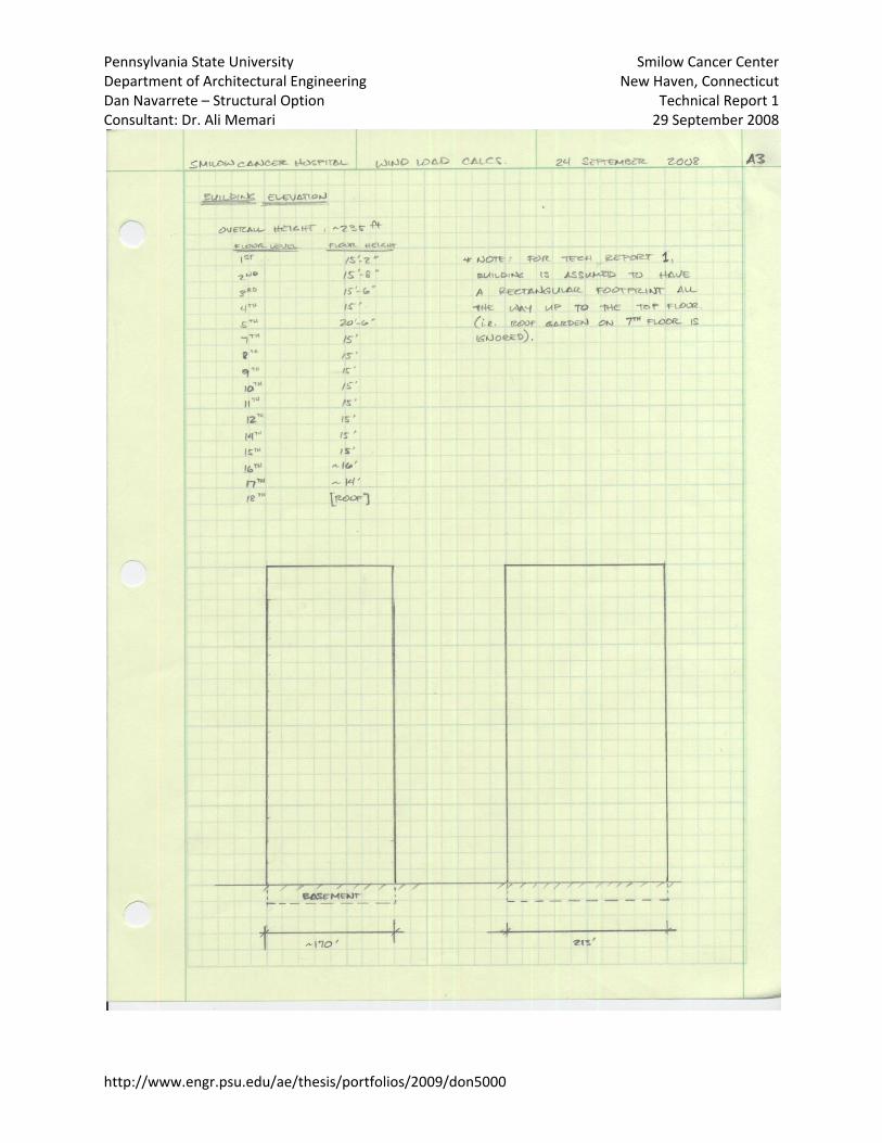
Height= 235 ft. B= 170 ft. L= 213 ft.
Location Height (ft.) Kz qz pz (psf)
Pz (kips) Overturning Moment, Mo (ft‐
kips)
Windward
30 0.70 25.2 16.6 42.45 1273.59 40 0.76 27.4 18.1 46.09 1843.68 50 0.81 29.2 19.3 49.12 2456.22 60 0.85 30.6 20.2 51.55 3093.01 70 0.89 32.1 21.2 53.98 3778.33 80 0.93 33.5 22.1 56.40 4512.16 90 0.96 34.6 22.8 58.22 5239.93 100 0.99 35.7 23.5 60.04 6004.08
120 1.04 37.5 24.7 63.07 7568.78
140 1.09 39.3 25.9 66.11 9254.78 160 1.13 40.7 26.9 68.53 10965.03
180 1.17 42.2 27.8 70.96 12772.32
200 1.2 43.2 28.5 72.78 14555.35 235 1.26 45.4 30.0 76.42 17957.67
Leeward ALL 1.26 45.4 ‐16.9 ‐42.98 ‐5050.59
Kh= 1.26
qh= 45.4 Eq. 6‐15
10 http://www.engr.psu.edu/ae/thesis/portfolios/2009/don5000

Pennsylvania State University Smilow Cancer Center Department of Architectural Engineering New Haven, Connecticut Dan Navarrete – Structural Option Technical Report 1 Consultant: Dr. Ali Memari 29 September 2008 Table 2b: Wind Pressure E‐W
East‐West Wind Direction (long side of building)
Height= 235 ft. B= 213 ft. L= 170 ft.
Location Height (ft.) Kz qz pz (psf)
Pz (kips) Overturning Moment, Mo (ft‐
kips)
Windward
30 0.70 25.2 16.6 53.05 1591.59
40 0.76 27.4 18.0 57.60 2304.02
50 0.81 29.2 19.2 61.39 3069.50 60 0.85 30.6 20.2 64.42 3865.29 70 0.89 32.1 21.1 67.45 4721.72 80 0.93 33.5 22.1 70.48 5638.78 90 0.96 34.6 22.8 72.76 6548.26 100 0.99 35.7 23.5 75.03 7503.22
120 1.04 37.5 24.7 78.82 9458.60
140 1.09 39.3 25.9 82.61 11565.56 160 1.13 40.7 26.8 85.64 13702.84 180 1.17 42.2 27.8 88.67 15961.38 200 1.2 43.2 28.5 90.95 18189.61 235 1.26 45.4 29.9 95.50 22441.43
Leeward ALL 1.26 45.4 ‐18.7 ‐59.68 ‐7012.95
Kh= 1.26
qh= 45.4 Eq. 6‐15
Notes:
1. Building footprint is assumed to be rectangular throughout height of structure.
2. All equations, tables, and sections cited are from ASCE/SEI 7‐05.
11 http://www.engr.psu.edu/ae/thesis/portfolios/2009/don5000
Pennsylvania State University Smilow Cancer Center Department of Architectural Engineering New Haven, Connecticut Dan Navarrete – Structural Option Technical Report 1 Consultant: Dr. Ali Memari 29 September 2008
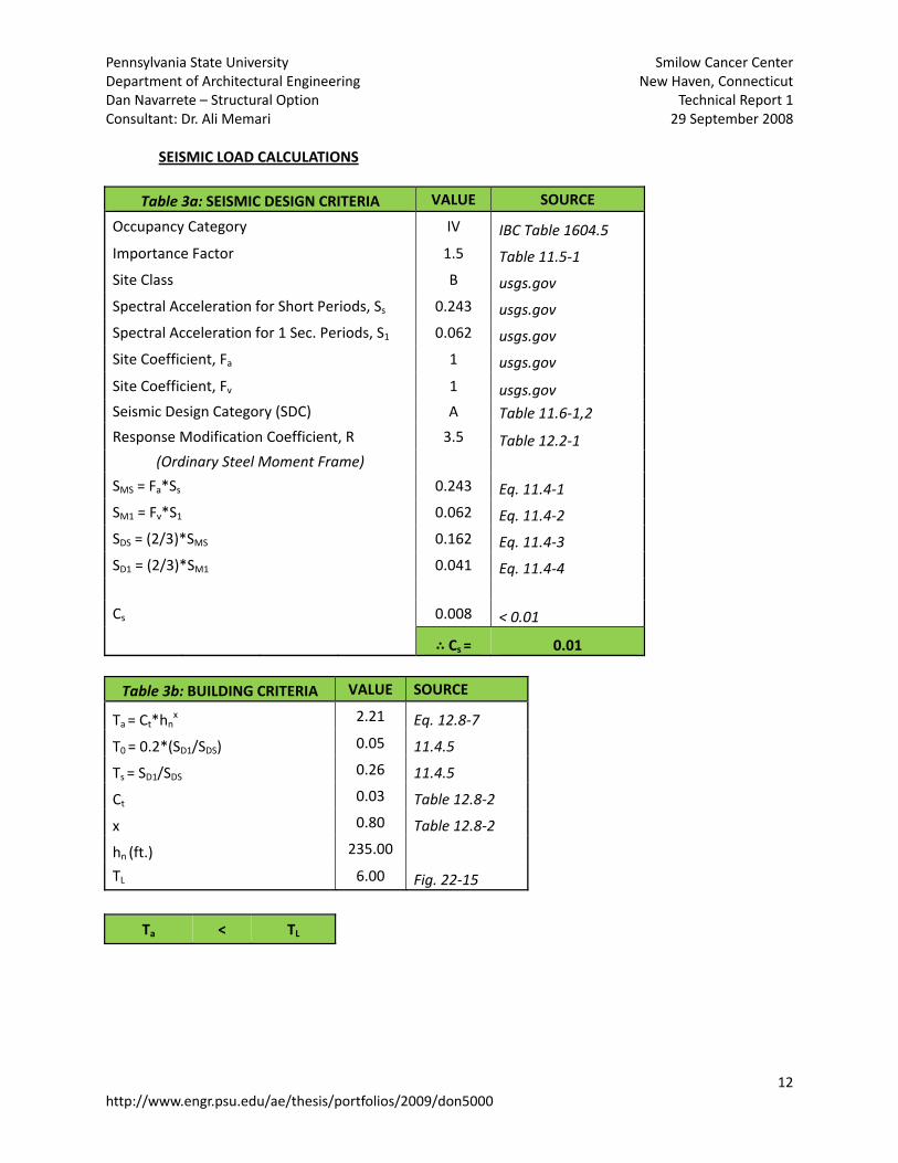
SEISMIC LOAD CALCULATIONS
Table 3a: SEISMIC DESIGN CRITERIA VALUE SOURCE
Occupancy Category IV IBC Table 1604.5 Importance Factor 1.5 Table 11.5‐1 Site Class B usgs.gov Spectral Acceleration for Short Periods, Ss 0.243 usgs.gov Spectral Acceleration for 1 Sec. Periods, S1 0.062 usgs.gov Site Coefficient, Fa 1 usgs.gov
Site Coefficient, Fv 1 usgs.gov Seismic Design Category (SDC) A Table 11.6‐1,2
Response Modification Coefficient, R 3.5 Table 12.2‐1 (Ordinary Steel Moment Frame)
SMS = Fa*Ss 0.243 Eq. 11.4‐1 SM1 = Fv*S1 0.062 Eq. 11.4‐2 SDS = (2/3)*SMS 0.162 Eq. 11.4‐3 SD1 = (2/3)*SM1 0.041 Eq. 11.4‐4 Cs 0.008 < 0.01
Cs = 0.01
Table 3b: BUILDING CRITERIA VALUE SOURCE
Ta = Ct*hnx 2.21 Eq. 12.8‐7
T0 = 0.2*(SD1/SDS) 0.05 11.4.5
Ts = SD1/SDS 0.26 11.4.5
Ct 0.03 Table 12.8‐2
x 0.80 Table 12.8‐2
hn (ft.) 235.00
TL 6.00 Fig. 22‐15
Ta < TL
12 http://www.engr.psu.edu/ae/thesis/portfolios/2009/don5000

Pennsylvania State University Smilow Cancer Center Department of Architectural Engineering New Haven, Connecticut Dan Navarrete – Structural Option Technical Report 1 Consultant: Dr. Ali Memari 29 September 2008
Table 3c: EFFECTIVE SEISMIC WEIGHT, W Dead Load
Superimposed lbs/ft Area (ft2) Total Weight (kips)
First Level 35 36210 1267.35
Second Level 25 36210 905.25
Third Level 25 36210 905.25
Fourth Level 35 36210 1267.35
Fifth Level 25 36210 905.25
Seventh Level 35 27210 952.35
Intermediate Roof 575 9000 5175
Eighth Level 25 27210 680.25
Ninth Level 25 27210 680.25
Tenth Level 25 27210 680.25
Eleventh Level 25 27210 680.25
Twelfth Level 25 27210 680.25
Fourteenth Level 25 27210 680.25
Fifteenth Level 25 27210 680.25
Sixteenth Level 25 27210 680.25
Seventeenth Level 25 27210 680.25
Roof 25 680 17.00
[see S605‐S606 of drawings for typical load diagrams]
Special Equipment Loads Weight (kips)
MRI Signa Twinspeed 1.5T 13.11 MRI Signa Signa Excite 3.0T 23.12 CT ‐ Lightspeed PRO 16 4.20 PET/CT Discovery ST 7.92 RAD ‐ Revolution XR/D 1.39 RAD/Flouro ‐ Precision 500D 3.44 Gamma ‐ Infinia w/ Hawkeye Option 6.39 Emergency Diesel Generators 35.00
[loads taken from S607 of drawings]
Storage Space: 25% of LL Area (ft2) Weight (kips)
First Level
0.25x125 psf
600 18.75 Second Level 420 13.13 Third Level 404 12.63 Fourth Level 328 10.25 Fifth Level 0 0.00 Seventh Level 1060 33.13 Eighth Level 200 6.25
13 http://www.engr.psu.edu/ae/thesis/portfolios/2009/don5000

Pennsylvania State University Smilow Cancer Center Department of Architectural Engineering New Haven, Connecticut Dan Navarrete – Structural Option Technical Report 1 Consultant: Dr. Ali Memari 29 September 2008
132 Ninth Level 4.13 Tenth Level 132 4.13 Eleventh Level 240 7.50 Twelfth Level 240 7.50 Fourteenth Level 210 6.56 Fifteenth Level 210 6.56 Sixteenth Level 0 0.00 Seventeenth Level 0 0.00 Roof 0 0.00
[see S605‐S606 of drawings for typical load diagrams]
Partition Load Area (ft2) Weight (kips)
First Level
20 psf [assumed]
36210 724.2 Second Level 36210 724.2 Third Level 36210 724.2 Fourth Level 36210 724.2 Fifth Level 36210 724.2 Seventh Level 27210 544.2 Eighth Level 27210 544.2 Ninth Level 27210 544.2 Tenth Level 27210 544.2 Eleventh Level 27210 544.2 Twelfth Level 27210 544.2 Fourteenth Level 27210 544.2 Fifteenth Level 27210 544.2 Sixteenth Level 27210 544.2 Seventeenth Level 27210 544.2 Roof 680 13.60
*NOTE: Snow load for area = 30 psf no 20% addition to effective seismic weight
TOTAL EFFECTIVE SEISMIC WEIGHT, W = 26818.72 kips
SEISMIC BASE SHEAR, V = 268.19 kips
14 http://www.engr.psu.edu/ae/thesis/portfolios/2009/don5000
Linear interpolation for exponent k:
Tmin Ta Tmax 0.5 2.21 2.5 k 1 1.86 2
k = 1.86
Pennsylvania State University Smilow Cancer Center Department of Architectural Engineering New Haven, Connecticut Dan Navarrete – Structural Option Technical Report 1 Consultant: Dr. Ali Memari 29 September 2008
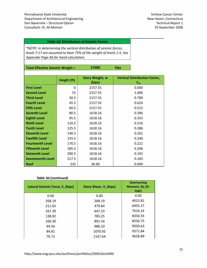
Table 3d: Distribution of Seismic Forces
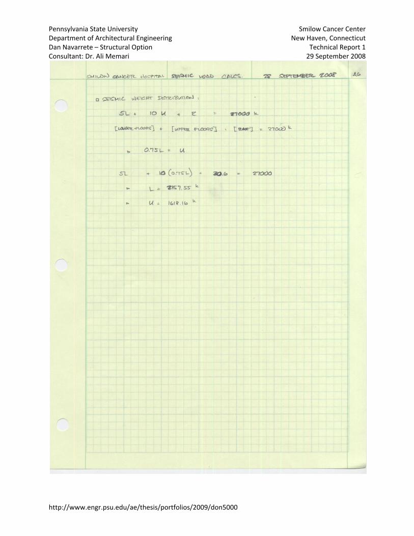
*NOTE: In determining the vertical distribution of seismic forces, levels 7‐17 are assumed to have 75% of the weight of levels 1‐5. See Appendix Page A6 for hand calculation. Total Effective Seismic Weight ≈ 27000 kips
Height (ft)
Story Weight, w (kips)
Vertical Distribution Factor, Cvx
First Level 0 2157.55 0.000 Second Level 15 2157.55 1.000 Third Level 30.5 2157.55 0.789 Fourth Level 45.5 2157.55 0.624 Fifth Level 60.5 2157.55 0.515 Seventh Level 80.5 1618.16 0.396 Eighth Level 95.5 1618.16 0.353 Ninth Level 110.5 1618.16 0.316 Tenth Level 125.5 1618.16 0.286 Eleventh Level 140.5 1618.16 0.261 Twelfth Level 155.5 1618.16 0.240 Fourteenth Level 170.5 1618.16 0.221 Fifteenth Level 185.5 1618.16 0.206 Sixteenth Level 200.5 1618.16 0.192 Seventeenth Level 217.5 1618.16 0.183
Roof 232 30.60 0.004 Table 3d (continued)
Lateral Seismic Force, Fx (kips) Story Shear, Vx (kips) Overturning
Moment, Mo (ft‐kips)
0.00 0.00 0.00
268.19 268.19 4022.81
211.65 479.84 6455.27
167.39 647.23 7616.24
138.02 785.25 8350.35
106.30 891.54 8556.75
94.56 986.10 9030.63
84.81 1070.92 9371.84
76.72 1147.64 9628.89
15 http://www.engr.psu.edu/ae/thesis/portfolios/2009/don5000

Pennsylvania State University Smilow Cancer Center Department of Architectural Engineering New Haven, Connecticut Dan Navarrete – Structural Option Technical Report 1 Consultant: Dr. Ali Memari 29 September 2008
16 http://www.engr.psu.edu/ae/thesis/portfolios/2009/don5000
69.96 1217.60 9829.52
64.25 1281.85 9990.56
59.37 1341.22 10122.76
55.17 1396.39 10233.29
51.51 1447.89 10327.14
48.98 1496.87 10653.26
1.04 1497.92 241.36 MEMBER SPOT‐CHECK Refer to pages A8‐A12 of Appendix for member spot‐check calculations and interpretation. CONCLUSION Being one of the more comprehensive cancer care facilities in the New England area, the Smilow Cancer Center features a relatively simple yet elegant and efficient structural system. The near‐square bays (approx. 30 ft by 30 ft) form a fairly orderly grid towards the west end of the plan, while the southeast quadrant of the building boasts four shear walls that shoot straight up through the building, providing part of the lateral resistance of the structure. The rest of the lateral load is handled by the six major moment frames located around the perimeter of the building and across the center. Calculating the wind and seismic loads of the building according to ASCE 7‐05 and testing typical member sizes reveal that gravity loading most likely does not control the design of the members. More than likely it is the case that lateral loading or even deflection and vibration limitations control the size of the members used. It is understandable that a hospital with its operating rooms and critical machinery would have very strict guidelines regarding the amount of vibration allowed. Furthermore, the importance of a hospital as a safe shelter during times of emergency definitely warrants the apparent over‐sizing of its structural members.

Pennsylvania State University Smilow Cancer Center Department of Architectural Engineering New Haven, Connecticut Dan Navarrete – Structural Option Technical Report 1 Consultant: Dr. Ali Memari 29 September 2008
http://www.engr.psu.edu/ae/thesis/portfolios/2009/don5000

Pennsylvania State University Smilow Cancer Center Department of Architectural Engineering New Haven, Connecticut Dan Navarrete – Structural Option Technical Report 1 Consultant: Dr. Ali Memari 29 September 2008
http://www.engr.psu.edu/ae/thesis/portfolios/2009/don5000

Pennsylvania State University Smilow Cancer Center Department of Architectural Engineering New Haven, Connecticut Dan Navarrete – Structural Option Technical Report 1 Consultant: Dr. Ali Memari 29 September 2008
http://www.engr.psu.edu/ae/thesis/portfolios/2009/don5000
Pennsylvania State University Smilow Cancer Center Department of Architectural Engineering New Haven, Connecticut Dan Navarrete – Structural Option Technical Report 1 Consultant: Dr. Ali Memari 29 September 2008
http://www.engr.psu.edu/ae/thesis/portfolios/2009/don5000

Pennsylvania State University Smilow Cancer Center Department of Architectural Engineering New Haven, Connecticut Dan Navarrete – Structural Option Technical Report 1 Consultant: Dr. Ali Memari 29 September 2008
http://www.engr.psu.edu/ae/thesis/portfolios/2009/don5000

Pennsylvania State University Smilow Cancer Center Department of Architectural Engineering New Haven, Connecticut Dan Navarrete – Structural Option Technical Report 1 Consultant: Dr. Ali Memari 29 September 2008
http://www.engr.psu.edu/ae/thesis/portfolios/2009/don5000
Pennsylvania State University Smilow Cancer Center Department of Architectural Engineering New Haven, Connecticut Dan Navarrete – Structural Option Technical Report 1 Consultant: Dr. Ali Memari 29 September 2008
http://www.engr.psu.edu/ae/thesis/portfolios/2009/don5000

Pennsylvania State University Smilow Cancer Center Department of Architectural Engineering New Haven, Connecticut Dan Navarrete – Structural Option Technical Report 1 Consultant: Dr. Ali Memari 29 September 2008
http://www.engr.psu.edu/ae/thesis/portfolios/2009/don5000

Pennsylvania State University Smilow Cancer Center Department of Architectural Engineering New Haven, Connecticut Dan Navarrete – Structural Option Technical Report 1 Consultant: Dr. Ali Memari 29 September 2008
http://www.engr.psu.edu/ae/thesis/portfolios/2009/don5000

Pennsylvania State University Smilow Cancer Center Department of Architectural Engineering New Haven, Connecticut Dan Navarrete – Structural Option Technical Report 1 Consultant: Dr. Ali Memari 29 September 2008
http://www.engr.psu.edu/ae/thesis/portfolios/2009/don5000

Pennsylvania State University Smilow Cancer Center Department of Architectural Engineering New Haven, Connecticut Dan Navarrete – Structural Option Technical Report 1 Consultant: Dr. Ali Memari 29 September 2008
http://www.engr.psu.edu/ae/thesis/portfolios/2009/don5000

Pennsylvania State University Smilow Cancer Center Department of Architectural Engineering New Haven, Connecticut Dan Navarrete – Structural Option Technical Report 1 Consultant: Dr. Ali Memari 29 September 2008
http://www.engr.psu.edu/ae/thesis/portfolios/2009/don5000

Pennsylvania State University Smilow Cancer Center Department of Architectural Engineering New Haven, Connecticut
http://www.engr.psu.edu/ae/thesis/portfolios/2009/don5000
Dan Navarrete – Structural Option Technical Report 1 Consultant: Dr. Ali Memari 29 September 2008