repair of corroded and buckled short steel columns using...
TRANSCRIPT

Construction and Building Materials 94 (2015) 20–27
Contents lists available at ScienceDirect
Construction and Building Materials
journal homepage: www.elsevier .com/locate /conbui ldmat
Repair of corroded and buckled short steel columns using concrete-filledGFRP jackets
http://dx.doi.org/10.1016/j.conbuildmat.2015.06.0400950-0618/� 2015 Elsevier Ltd. All rights reserved.
⇑ Corresponding author.E-mail address: [email protected] (M. Dawood).
A. Kaya, M. Dawood ⇑, B. GencturkDepartment of Civil and Environmental Engineering, University of Houston, N107 Engineering Building 1, Houston, TX 77204-4003, United States
a r t i c l e i n f o a b s t r a c t
Article history:Received 10 March 2015Accepted 17 June 2015
Keywords:Corroded steel columnsRehabilitation and repairGlass fiber reinforced polymers (GFRP)BucklingGFRP confined concrete
Many bridges and structures in the United States that are supported on steel columns or piles exhibitinadequate strength due to increasing load demand or aging due to corrosion, or both. The combinationof increased load demand and reduction of capacity due to corrosion-induced section loss can lead tounexpected buckling of the piles. This paper investigates the effectiveness of a glass fiber reinforced poly-mer (GFRP)-based technique for rapid retrofit of buckled steel piles or columns. The system consists of aGFRP jacket, which is formed on-site and subsequently filled with an expansive concrete.Thirteen-buckled short steel columns with varying degrees of section loss were repaired and tested tofailure under axial compression. The research results indicate that the repair system restored the capacityof the buckled columns to between 69% and 104% of the capacity of the undamaged control column.Further the repaired piles exhibited a hardening response in the non-linear range rather than the suddenloss of capacity and softening response that is characteristically associated with buckling of steel col-umns. The findings suggest that installation of concrete-filled GFRP jackets can be an effective techniqueto rapidly repair corroded and buckled short steel columns or piles.
� 2015 Elsevier Ltd. All rights reserved.
1. Introduction bridges by Liu et al. [14]. Various retrofit lengths were investigated
Steel piles and columns in bridges, marine structures, industrialfacilities, and warehouses are particularly susceptible to corrosion.Failure of these critical load-bearing members could result in par-tial or total structural collapse that may require an urgent or emer-gency repair. Traditional repair techniques include welding orbolting steel plates, or casting large reinforced concrete jacketsaround the corroded section. The use of fiber reinforced polymer(FRP) composites instead of, or along with conventional construc-tion materials is emerging as an alternative technique. In additionto being technically feasible, other claimed benefits of FRP-basedsystems include reduced cost, time, and labor associated with theinstallation. One common approach is to fabricate a cylindricalFRP shell, which is subsequently filled with a cementitious groutor concrete. The cementitious core, which may or may not be inter-nally reinforced, stabilizes the steel element and the FRP shell pro-vides confinement to the core. This intervention may beimplemented along the entire length of a column or locally atthe deteriorated segment.
The repair technique using FRP described above was investi-gated for strengthening of slender compression members of steel
to study the effect of the length of the repair on the capacity andoverall response of the repaired steel columns. Seven 3 m longS4x9.5 steel compression members were tested. The flanges ofthe elements were machined to represent the section loss due tocorrosion and subsequently repaired with concrete-filled GFRPtubes. The repaired members were tested monotonically and typi-cally failed by global buckling that initiated just outside of therepaired region. The research findings indicate that in some casesthe ultimate load carrying capacity of the repaired members wasnearly twice that of the undamaged control member. The research-ers further found that using expansive, lightweight concrete for thecore material provided greater increases of strength than usingnon-expansive core materials due to the improved bond providedby the active confinement of the expansive core. A simplifieddesign approach was also proposed in the same study to designthe repair system.
El-Tawil and Ekiz [5] proposed a two-step technique to inhibitbuckling of single- and double-angle brace members.Pre-fabricated mortar blocks were placed inside the root betweenthe legs of the steel angles. The assembly was subsequentlywrapped with different configurations of uniaxial wet lay-upCFRP. The retrofitted braces were subjected to reversed cyclic axialloads in a specially designed frame for testing steel braces. The ret-rofit system inhibited buckling of the braces up to inter-story drift
A. Kaya et al. / Construction and Building Materials 94 (2015) 20–27 21
levels of 2% and nearly doubled the cumulative energy dissipationof retrofitted braces compared to un-retrofitted braces at the samedrift level. The system was more effective for double-angle bracesthan for single-angle braces.
Han et al. [8] investigated the cyclic performance of circular andsquare so-called double-skin tubular columns. These membersconsist of a circular steel inner tube and a circular or squarebi-directional CFRP outer tube with a concrete core between thetubes. The columns were subjected to a constant axial load and areversed-cyclic flexural load of increasing amplitude. Failure ofthe columns was characterized by the rupture of the longitudinalcarbon fibers followed by rupture of the circumferential fibers.Post-failure evaluation of the columns revealed localized crushingof the concrete and inward buckling of the inner steel tubes. Thetest results indicated that increasing the axial load level of the col-umns increased their flexural ductility while increasing the num-ber of layers of carbon fiber reinforced polymer (CFRP) in theouter tube increased the strength but reduced the flexural ductilityof the columns.
In another study, 0.5 m long, W150 � 14 steel columns wereretrofitted with GFRP along their entire length and tested in axialcompression to failure [12]. Two different types of GFRP jacketswhich have different dimensions and material properties wereevaluated and the use of a shrinkage reducing chemical admixturein the concrete core was investigated. Concrete mixes with similarcompressive strength were used with and without a shrinkagereducing chemical admixture. The research suggested that shrink-age reduced the benefits of the confinement of the concrete coreand resulted in a lower compressive strength. This was attributedto the formation of a gap between the concrete core and the FRPjacket. Installation of the proposed system increased the compres-sive strength of the members by between 40% and 80% with largergains in strength being achieved by using the GFRP tube that hashigher lateral tensile strength and modulus.
In another study, Karimi et al. [13] developed a new configura-tion of steel–concrete-FRP composite column. The voids betweenthe flanges on either side of the web of a W150 � 14 steel columnwere filled with concrete. The composite element was subsequentlywrapped with CFRP or GFRP. Columns ranging in length from 0.5 to3.0 m were tested in axial compression. The compressive strengthof the composite columns was between 2 and 5 times that of theirbare steel counterparts. Similarly the elastic stiffnesses of the com-posite columns were between 2.1 and 2.5 times those of the baresteel control columns. Longer (more slender) columns generallyexhibited greater increases of strength relative to shorter (stockier)columns while elastic strength increases were uncorrelated withlength. All of the composite columns failed by global buckling.
Feng et al. [7] proposed a strengthening method for steel col-umns using mortar-filled pultruded GFRP tubes. Different steel sec-tion shapes were considered including I-shaped, cruciform, circulartubular, and square tubular sections. Additionally several layers ofFRP fabrics were wrapped around the ends of the FRP tubes to pre-vent localized splitting of the tubes. The lengths of the tested col-umns varied from 0.78 to 2.9 m. Installation of this retrofit schemeincreased the axial load carrying capacity and axial ductility of thetested members by up to 215% and 877%, respectively. The increaseof capacity was larger for longer (more slender) columns whichfailed by global buckling while shorter columns generally exhibiteda less dramatic strength increase after repair and they failed bylocalization of deformations outside of the repaired region.
Several other researchers have investigated the rehabilitation ofsteel compression members by directly bonding CFRP or GFRP mate-rials to the steel member [4,9,15]. These studies generally demon-strated moderate increases of capacity for the strengthenedmembers compared to plain steel control members. The greatestimprovements were generally found when relatively stiff
bi-directional CFRP materials were bonded to members with slen-der elements or when stiff CFRP plates were bonded to long, slendercolumns. In these cases the presence of the CFRP helped to postponelocal buckling for the former and global buckling for the latter.
2. Research significance
Previous studies have focused on evaluating the behavior ofnew, undamaged columns that are retrofitted with FRP materialsor those with simulated corrosion damage that are subsequentlyrepaired with FRP. However, in practical applications, columnswith severe corrosion may unexpectedly exhibit local or globalbuckling due to progress of corrosion between inspections or unin-tentional overload of the deteriorated member. In these applica-tions, stabilization using concrete-filled FRP jackets may presentan effective and rapidly deployable repair solution to maintainthe integrity of the structure until a more permanent repair orreplacement can be achieved. However, stabilization of buckledcolumns present unique challenges. Specifically, the buckled mem-bers exhibit large residual transverse deflections and reducedresidual strength compared to their unbuckled counterparts. Thiscan influence the effectiveness and ease of installation of the repairsystem. This paper presents the findings of an experimental pro-gram that was designed to evaluate the effectiveness of this tech-nique to repair corroded and buckled steel short columns. Thisserves as a first step towards developing comprehensive designguidelines for the implementation of this repair technique.
3. Experimental program
A total of thirteen short steel columns were tested in this study.The columns consisted of W4 � 13 (US designation) columns withdifferent patterns of simulated corrosion. The columns were previ-ously tested to evaluate the capacity of short steel columns withlocalized severe corrosion [11]. After testing, the columns wererepaired with different configurations of concrete-filled GFRP jack-ets to investigate the effectiveness of this repair technique. The con-figurations of the corrosion patterns are illustrated schematically inFig. 1. In the previous study, the columns were assigned uniqueidentifiers of up to five parts. The first two parts indicated the per-centage reduction of flange and web thickness, respectively. Thethird part of the identifier, V or NV, indicated the presence orabsence, respectively, of a 51 mm void at the mid-height of theweb to simulate through web corrosion. The fourth part, S or US,indicated a symmetric or unsymmetric corrosion pattern, respec-tively, as illustrated in Fig. 1. The final part, WR if present, indicatedthe presence of a semi-circular reduction of the flanges to simulatethe presence of flange perforations due to extreme corrosion.
In the current study, the columns that were previously tested byKaragah et al. [11] were put into four groups as summarized inTable 1. Specimens were grouped on the basis of similar simulatedcorrosion patterns, axial load–deflection response, failure modes,and residual loads at the conclusion of previous testing. Table 1summarizes the residual load and the initial out-of-straightnessof the tested piles prior to installation of the repairs. The residualload was obtained directly from the test data from the previoustesting. The initial out-of-straightness was measured by placingthe piles on a flat surface and measuring the maximum distancebetween the deformed columns and the surface. Additional detailsof the testing and observed behavior of the columns prior to repairare summarized elsewhere [11].
After the completion of the tests of the columns with simulatedcorrosion, the buckled columns were retrofitted withconcrete-filled GFRP jackets. In addition to the grouping of the col-umns, the primary parameters that were considered in this studywere the number of FRP layers in the jacket, and the details of

)nmuloCleetScirtemmysnU()nmuloCleetScirtemmyS(
Fig. 1. Schematic representation of the corrosion patterns of the tested steel columns (adapted from [11]).
Table 1Test matrix.
Designation Loss of crosssection (%)
Initial out ofstraightness (mm)
Residual load ofunrepairedcolumns (kN)
Retrofitting scheme No of GFRPlayers
Rebar Compressivestrength (kN)
Karagahet al. [11]
ThisStudy
Unrepaired Repaired
Group #1 0/0 G1/2/NR-1 0.0 15.1 809 Grout + GFRP 2 – 956 8980/30 G1/2/NR-2 9.0 7.9 769 Grout + GFRP 2 – 894 9070/60 G1/2/NR-3 16.1 11.1 408 Grout + GFRP 2 – 792 943
Group #2 50/0 G2/3/NR-1 39.9 11.1 408 Grout + GFRP 3 – 520 96150/30 G2/3/NR-2a 43.6 22.4 374 Grout + GFRP 3 – 578 874
Group #3 75/0 G3/2/4#3-1 58.9 6.4 325 Grout + GFRP + Rebar 2 4#3 409 91275/60 G3/2/4#3-2 67.6 4.0 205 Grout + GFRP + Rebar 2 4#3 311 73175/60/NV/US G3/3/4#3 75.4 11.1 176 Grout + GFRP + Rebar 3 4#3 253 99275/60/NV/US/WR G3/2/4#4 74.7 2.5 306 Grout + GFRP + Rebar 2 4#4 311 934
Group #4 75/60/V/S G4/2/NR 78.8 4.0 67 Grout + GFRP 2 – 178 66475/60/V/S/WR G4/2/4#4 88.3 3.2 64 Grout + GFRP + Rebar 2 4#4 160 29875/60/V/US G4/3/NR 78.8 6.4 62 Grout + GFRP 3 – 178 84075/60/V/US/WR G4/3/4#4 77.4 12.7 65 Grout + GFRP + Rebar 3 4#4 173 943
a Total length = 686 mm; repaired length = 521 mm.
22 A. Kaya et al. / Construction and Building Materials 94 (2015) 20–27
the supplemental longitudinal steel reinforcement inside the con-crete core as outlined in Table 1. To simplify the discussion, the ret-rofitted columns were each assigned new identifiers as listed in thetest matrix (see Table 1). These identifiers consisted of four parts.The first part, G#, indicates the specific group number (1, 2, 3, or4) of the tested column. The second part indicates the number ofGFRP layers in the jacket (2 or 3). The third part indicates no inter-nal reinforcement (NR) or the number and size of the internal lon-gitudinal reinforcing bars (4#3 or 4#4). The size designations ofthe reinforcing bars (#3 and #4) follow the US designation andindicate the diameter of the bars in 1/8th inch (1 inch = 25.4 mm)increments. Therefore, #3 and #4 reinforcing bars have nominaldiameters of 9.5 and 12.7 mm, respectively. The last part of theidentifier (1, 2, or 3), if present, is a serial number to indicate mul-tiple repetitions of the same test configuration. Due to the largeuncertainty associated with testing buckled and repaired columns,multiple repetitions were conducted for several test configurationsto evaluate the repeatability of the results.
4. Material properties
The following sections summarize the properties of the materi-als that were used in the fabrication of the test columns, includingstructural steel, concrete, reinforcing bars, and GFRP jackets.
4.1. Structural steel
Karagah et al. [11] reported the properties of the structural steelthat were used for the tested columns. The tensile properties wereobtained from two tensile coupons taken from the web and fourcoupons taken from the flanges of the tested section. One406 mm long stub column was also tested to evaluate the com-pression properties and residual stresses of the steel. The stub col-umn was loaded concentrically at a rate of 0.2 mm/inch. The top ofthe columns was pinned about both axes and the bottom was fixedagainst rotation about both axes. The stub column failed by globalbuckling. Table 2 summarizes the material properties of the steel.
4.2. GFRP jackets
The GFRP jackets were produced using a commercially avail-able, flexible, pre-cured, bidirectional GFRP laminate. This laminateis flexible enough to be wrapped into a multi-layered cylinder ofthe desired diameter. Five tension coupons were tested, accordingto [2] from each of the longitudinal (0�), transverse (90�) and (45�)directions of the laminate to determine the tensile properties. Thelaminates were oriented such that the longitudinal direction of theGFRP corresponded with the hoop direction of the jacket while thetransverse direction of the GFRP corresponded with the axial

Table 2Mechanical properties of steel columns [11].
Designation Modulus ofelasticity
Yieldstrength
Ultimatestrength
Strain at ultimatestrength
(GPa) (MPa) (MPa) (mm/mm)
Stub column(compression)
208 369 N/Aa N/Aa
Flange (tension) 186 387 478 0.133Web (tension) 180 439 530 0.070
a Not applicable.
Table 3Mechanical properties of the GFRP laminate.
Property Longitudinal (0�) Transverse (90�)
Mean COV (%)a Mean COV (%)a
Tensile strength (MPa) 397 23 392 7Tensile modulus (MPa) 21,918 15 18,416 10Ultimate strain (%) 1.89 24 2.2 9Poisson’s ratio 0.28 0.26b
Shear modulus (MPa) 1731
a Coefficient of variation.b Calculated as mij = (Ei * mji)/Ej based on symmetry of the material stiffness matrix
[10].
Table 4Properties of the adhesive (Quakewrap, N.D.).
Property Value
Tensile strength (MPa) 30Tensile modulus (MPa) 2268Compressive strength (MPa) 55Compressive modulus (MPa) 1923Flexural strength (MPa) 55Flexural modulus (MPa) 1725Shear strength (MPa) 10
A. Kaya et al. / Construction and Building Materials 94 (2015) 20–27 23
direction of the columns. Table 3 summarizes the mechanicalproperties of the GFRP laminate that were used in this study.
The GFRP laminate was wrapped into a multi-layer cylinder forthe repair. Both surfaces of the GFRP were sanded, wiped clean,and coated with an epoxy-based adhesive to bond the laminateto itself to form the cylinder. Table 4 summarizes the propertiesof the adhesive, as reported by the manufacturer.
4.3. Concrete
The columns tested in this study were repaired in four batches.Therefore, four distinct batches of concrete were produced, eachwith slightly different properties. Table 5 summarizes the targetproportions of the concrete mixture. To ensure intimate contactbetween the concrete, the FRP jacket, and the steel column, a
Table 5Proportions of the concrete mixture and cylinder test results.
Casting group Mixture by weightratio
Designation of columns
Grout Gravel Water
Group #1 1.0 0.5 0.17 G1/2/NR-1, G1/2/NR-2, G2/3/NR-1, G2/3/NRGroup #2 1.0 0.5 0.15 G1/2/NR-3, G3/2/4#3-1, G4/2/NRGroup #3 1.0 0.5 0.15 G3/2/4#3-2, G3/3/4#3, G3/2/4#4Group #4 1.0 0.5 0.15 G4/2/4#4, G4/3/NR, G4/3/4#4
a Cylinders were tested at the start and end of the column tests for each group.b Coefficient of variation.
commercially available expansive cementitious material was usedin the preparation of the concrete [6]. The compressive strength ofthe concrete was determined by testing 102 mm diame-ter � 203 mm long concrete cylinders according to [3] immedi-ately before and after testing of the repaired columns from thesame batch of concrete. For all four batches, the compressivestrength was found to remain approximately constant after14 days of curing. Table 5 summarizes the mean and the coefficientof variation (COV) of the compressive strengths for the four differ-ent batches of the concrete.
4.4. Reinforcing bars
The tensile properties of the reinforcing bars were obtained bytesting representative samples according to ASTM A370 [1]. Twosamples were tested for each reinforcing bar diameter. Table 6summarizes the mechanical properties of the reinforcing bars.The tensile modulus was obtained by fitting a best-fit line to thelinear portion of the stress–strain curve between stress levels of34.5 and 276 MPa. The yield strength was obtained by the 0.2% off-set method. The ultimate strength was determined directly fromload measurement and the nominal cross-sectional areas of the#3 and #4 reinforcing bars.
5. Specimen fabrication
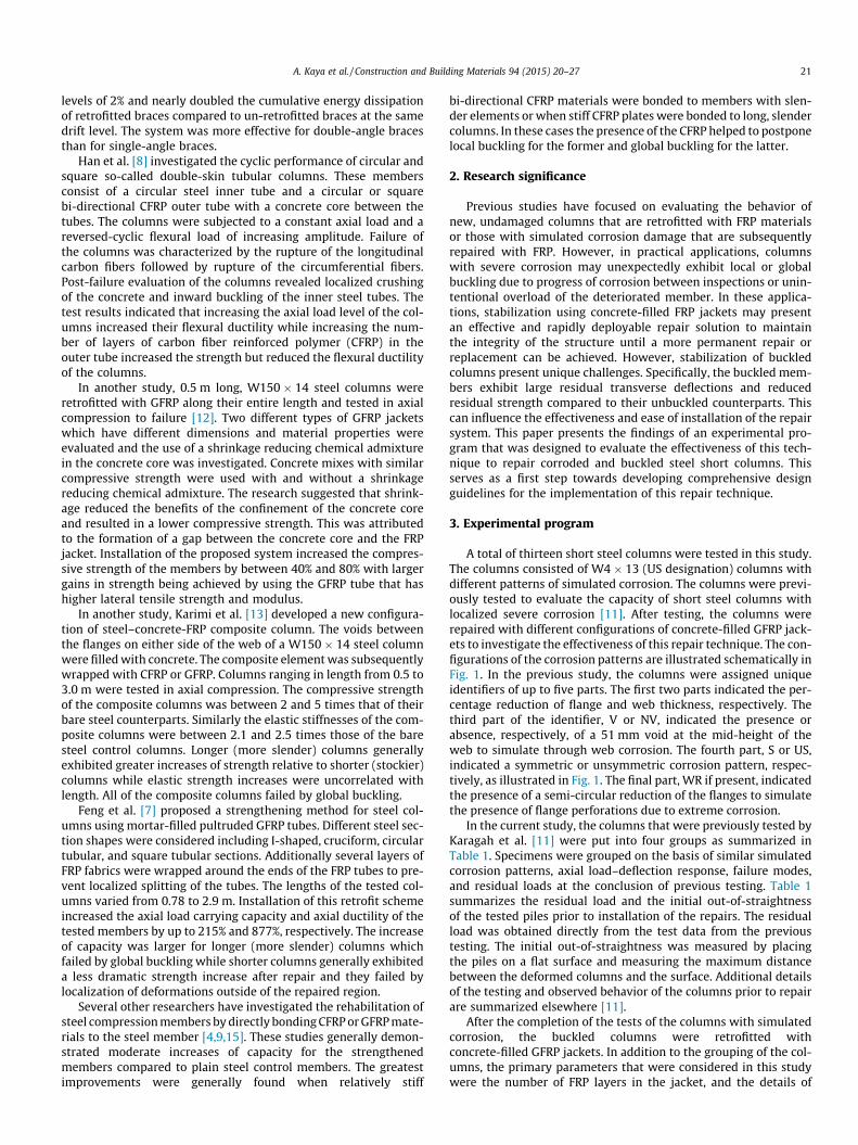
The GFRP jackets that were used in this study were fabricatedfrom a continuous flexible GFRP laminate that was wrappedaround the pile and bonded to itself to produce a multi-layeredclosed, circular GFRP tube around the pile. The benefit of this sys-tem is that the GFRP tube can be manufactured on site to anylength, diameter, and thickness desired to meet the demands ofthe specific repair application at hand. The repair procedureincluded nine steps: (1) the steel surface was cleaned using a wirebrush and alcohol; (2) the GFRP sheets were cut to the appropriatedimensions; (3) wooden spacers were placed on the flanges of thesteel columns to prevent direct contact between the steel columnsand the GFRP jackets; (4) the GFRP jackets were wrapped aroundthe steel columns to a nominal diameter of 203 mm; (5) thetwo-component epoxy was mixed for 3 min using a low speedmixer until achieving a uniform color; (6) the epoxy was appliedto both sides of the GFRP laminate prior to wrapping the laminatearound the column; (7) the jacket was secured using plastic zip tiesfor 48 h while the epoxy cured; (8) the reinforcing bars wereplaced inside the jackets (depending on the specimen); and (9)the grout and gravel were mixed using a gravity-based mixerand cast into the FRP jackets. Fig. 2 shows a schematic representa-tion of the repaired columns.
6. Test setup and instrumentation
The specimens were tested under monotonic compression loadusing a 1780 kN capacity Tinius-Olsen universal testing machine.
Age of concrete at testingof cylinders (days) a
Number of cylinderstested
Compressivestrength
Mean (MPa) COV (%)b
-2 14–18 9 51 424–29 5 63 398–119 5 71 318–28 4 59 2
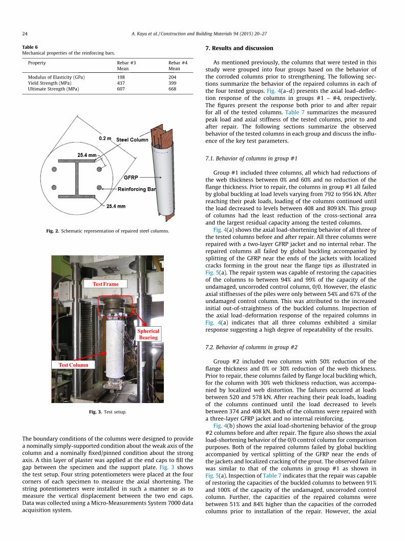
Table 6Mechanical properties of the reinforcing bars.
Property Rebar #3 Rebar #4Mean Mean
Modulus of Elasticity (GPa) 198 204Yield Strength (MPa) 437 399Ultimate Strength (MPa) 607 668
Fig. 2. Schematic representation of repaired steel columns.
Test Frame
Test Column
Spherical Bearing
Fig. 3. Test setup.
24 A. Kaya et al. / Construction and Building Materials 94 (2015) 20–27
The boundary conditions of the columns were designed to providea nominally simply-supported condition about the weak axis of thecolumn and a nominally fixed/pinned condition about the strongaxis. A thin layer of plaster was applied at the end caps to fill thegap between the specimen and the support plate. Fig. 3 showsthe test setup. Four string potentiometers were placed at the fourcorners of each specimen to measure the axial shortening. Thestring potentiometers were installed in such a manner so as tomeasure the vertical displacement between the two end caps.Data was collected using a Micro-Measurements System 7000 dataacquisition system.
7. Results and discussion
As mentioned previously, the columns that were tested in thisstudy were grouped into four groups based on the behavior ofthe corroded columns prior to strengthening. The following sec-tions summarize the behavior of the repaired columns in each ofthe four tested groups. Fig. 4(a–d) presents the axial load–deflec-tion response of the columns in groups #1 – #4, respectively.The figures present the response both prior to and after repairfor all of the tested columns. Table 7 summarizes the measuredpeak load and axial stiffness of the tested columns, prior to andafter repair. The following sections summarize the observedbehavior of the tested columns in each group and discuss the influ-ence of the key test parameters.
7.1. Behavior of columns in group #1
Group #1 included three columns, all which had reductions ofthe web thickness between 0% and 60% and no reduction of theflange thickness. Prior to repair, the columns in group #1 all failedby global buckling at load levels varying from 792 to 956 kN. Afterreaching their peak loads, loading of the columns continued untilthe load decreased to levels between 408 and 809 kN. This groupof columns had the least reduction of the cross-sectional areaand the largest residual capacity among the tested columns.
Fig. 4(a) shows the axial load-shortening behavior of all three ofthe tested columns before and after repair. All three columns wererepaired with a two-layer GFRP jacket and no internal rebar. Therepaired columns all failed by global buckling accompanied bysplitting of the GFRP near the ends of the jackets with localizedcracks forming in the grout near the flange tips as illustrated inFig. 5(a). The repair system was capable of restoring the capacitiesof the columns to between 94% and 99% of the capacity of theundamaged, uncorroded control column, 0/0. However, the elasticaxial stiffnesses of the piles were only between 54% and 67% of theundamaged control column. This was attributed to the increasedinitial out-of-straightness of the buckled columns. Inspection ofthe axial load–deformation response of the repaired columns inFig. 4(a) indicates that all three columns exhibited a similarresponse suggesting a high degree of repeatability of the results.
7.2. Behavior of columns in group #2
Group #2 included two columns with 50% reduction of theflange thickness and 0% or 30% reduction of the web thickness.Prior to repair, these columns failed by flange local buckling which,for the column with 30% web thickness reduction, was accompa-nied by localized web distortion. The failures occurred at loadsbetween 520 and 578 kN. After reaching their peak loads, loadingof the columns continued until the load decreased to levelsbetween 374 and 408 kN. Both of the columns were repaired witha three-layer GFRP jacket and no internal reinforcing.
Fig. 4(b) shows the axial load-shortening behavior of the group#2 columns before and after repair. The figure also shows the axialload-shortening behavior of the 0/0 control column for comparisonpurposes. Both of the repaired columns failed by global bucklingaccompanied by vertical splitting of the GFRP near the ends ofthe jackets and localized cracking of the grout. The observed failurewas similar to that of the columns in group #1 as shown inFig. 5(a). Inspection of Table 7 indicates that the repair was capableof restoring the capacities of the buckled columns to between 91%and 100% of the capacity of the undamaged, uncorroded controlcolumn. Further, the capacities of the repaired columns werebetween 51% and 84% higher than the capacities of the corrodedcolumns prior to installation of the repair. However, the axial

0
100
200
300
400
500
600
700
800
900
1000
0 0.5 1 1.5 2 2.5 3
Load
(kN
)
Axial Shortening (%)
G1/2/NR-1
G1/2/NR-2
0/30
G1/2/NR-30/0
0/60Karagah et al. (2015) This Study
0/0 G1/2/NR-10/30 G1/2/NR-20/60 G1/2/NR-3
a
0
100
200
300
400
500
600
700
800
900
1000
0 0.5 1 1.5 2 2.5 3
Load
(kN
)
Axial Shortening (%)
G2/3/NR-2
50/30
0/0
50/0
G2/3/NR-1
Karagah et al. (2015) This Study50/0 G2/3/NR-1
50/30 G2/3/NR-2
b
0
100
200
300
400
500
600
700
800
900
1000
0 0.5 1 1.5 2 2.5 3
Load
(kN
)
Axial Shortening (%)
G3/2/4#3-2G3/2/4#4
G3/3/4#3
0/0
75/60/NV/US/WR
75/6075/60/NV/US
75/0
G3/2/4#3-1
Karagah et al. (2015) This Study75/0 G3/2/4#3-1
75/60 G3/2/4#3-275/60/NV/US G3/3/4#3
75/60/NV/US/WR G3/2/4#4
c
0
100
200
300
400
500
600
700
800
900
1000
0 0.5 1 1.5 2 2.5 3
Load
(kN
)
Axial Shortening(%)
G4/2/NR
0/0
75/60/V/S
G4/2/4#4
75/60/V/S/WR
G4/3/NR
75/60/V/US
G4/3/4#4
75/60/V/US/WRKaragah et al. (2015)This Study
75/60/V/S G4/2/NR75/60/V/S/WR G4/2/4#4
75/60/V/US G4/3/NR75/60/V/US/WR G4/3/4#4
d
Fig. 4. Axial load-shortening behavior of the columns (a) group #1, (b) group #2, (c) group #3 and (d) group #4.
Table 7Test results.
Designation Initial out ofstraightness (mm)
Peak axial load (kN) Axial stiffness (kN/mm) Failure mode
Unrepaired, Pun Repaired, Pr Pr/Pun Pr=P�0 Unrepaired, Kun Repaired, Kr Kr/Kun
Group #1 G1/2/NR-1 15.1 956 898 0.940 0.940 619 336 0.543 Global buckling/ruptureG1/2/NR-2 7.9 894 907 1.015 0.949 731 408 0.558 Global buckling/ruptureG1/2/NR-3 11.1 792 943 1.191 0.986 622 416 0.669 Global buckling/rupture
Group #2 G2/3/NR-1 11.1 520 961 1.846 1.005 655 322 0.492 Global buckling/ruptureG2/3/NR-2 22.4 578 874 1.512 0.914 633 236 0.373 Global buckling/rupture
Group #3 G3/2/4#3-1 6.4 409 912 2.228 0.953 421 430 1.020 RuptureG3/2/4#3-2 4.0 311 731 2.349 0.765 366 369 1.009 DebondingG3/3/4#3 11.1 254 992 3.912 1.037 359 408 1.134 Global bucklingG3/2/4#4 2.5 311 934 3.000 0.977 410 354 0.865 Rupture
Group #4 G4/2/NR 4.0 173 664 3.826 0.694 240 235 0.980 RuptureG4/2/4#4 3.2 160 298 1.861 0.312 339 232 0.684 Grout fracture at voidG4/3/NR 6.4 178 840 4.723 0.879 338 267 0.788 RuptureG4/3/4#4 12.7 173 943 5.436 0.986 286 208 0.727 Global buckling
P�0 Peak axial load of undamaged, uncorroded control column.
A. Kaya et al. / Construction and Building Materials 94 (2015) 20–27 25
stiffnesses of the repaired columns were between 38% and 52% ofthat of the control column which was again attributed to the highinitial out-of-straightness of the buckled columns.
7.3. Behavior of columns in group #3
Group #3 included four columns with 75% reduction of theflange thickness and 0% or 60% reduction of the web thickness.Prior to repair the columns all failed by flange local buckling which,in the case of columns with a 60% reduction of the web thickness,
was accompanied by localized distortion of the web. The failureloads were between 253 and 409 kN. After reaching their peakloads, loading of the columns continued until the load decreasedto levels between 176 and 325 kN.
Fig. 4(c) shows the axial load-shortening behavior of the group#3 columns before and after repair. The figure also presents theaxial load-shortening behavior of the 0/0 control column for com-parison purposes. Due to the extensive section loss and reductionof capacity of these columns, extra measures were implementedto increase the effectiveness of the repair system. Columns

a edcb
Fig. 5. Failure of test columns (a) G2/3/NR-2 (b) G3/2/4#3-2 (c) G3/2/4#4 (d) G3/3/4#3 (e) G4/2/4#4.
26 A. Kaya et al. / Construction and Building Materials 94 (2015) 20–27
G3/2/4#3-1 and G3/2/4#3-2 were both repaired with two-layerGFRP jackets and four 9.5 mm diameter steel internal reinforcingbars. Column G3/2/4#3-1 failed by global buckling and ruptureof the GFRP, as illustrated in Fig. 5(c), at a load level of 912 kN,which corresponded to 95% of the capacity of the uncorroded con-trol column. Column G3/2/4#3-2 was the only column for whichthe surface of the GFRP jacket was only sanded on one side priorto installation. Consequently, the column failed by delaminationof the GFRP jacket, as shown in Fig. 5(b). Delamination initiatedat the free end of the GFRP at a load level of 730 kN. This load levelcorresponded to the 76% of the capacity of the uncorroded controlcolumn. The failure of this column highlights the importance ofproper surface preparation and bonding of the jacket prior toinstallation.
Column G3/2/4#4 was similar to the previous two columns, butincluded 12.7 mm diameter internal steel reinforcing bars ratherthan 9.5 mm diameter bars. The repaired column failed due toGFRP rupture as shown in Fig. 5(c) at a load level of 934 kN, whichcorresponded to 98% of the capacity of the control column.
Column G3/3/4#3 was repaired with a three-layer GFRP jacketrather than a two-layer jacket like the previous columns. It faileddue to global buckling of the column without rupture of jacket asshown in Fig. 5(d) at a load level of 992 kN, which correspondedto 104% of the capacity of the control column. Testing was haltedwhen excessive rotation was observed at the upper and lower sup-ports. Comparison of the behavior to that of column G3/2/4#3-1indicates that increasing the jacket thickness helped to increasethe failure load by 9%. Further, increasing the jacket thickness pre-vented rupture of the jacket at failure.
7.4. Behavior of columns in group #4
Group #4 included four columns with a 75% reduction of theflange thickness, 60% reduction of the web thickness, and a voidin the web to simulate through-corrosion. Prior to repair the col-umns all failed by localized buckling of the flanges on either sideof the web void at loads between 160 and 178 kN. After reachingtheir peak loads, loading of the columns continued until the loaddecreased to levels between 62 and 67 kN.
Fig. 4(d) shows the axial load-shortening behavior of the group#4 columns before and after repair along with the behavior of the0/0 control column for comparison purposes. Columns G4/2/NRand G4/3/NR were similar except that they were repaired with
two-layer and three-layer GFRP jackets, respectively. Comparisonof the results indicates that both columns exhibited a similar trendof behavior. Both columns failed by rupture of the GFRP jacket asillustrated in Fig. 5(c) at loads of 664 and 841 kN, respectively.The results indicate that increasing the number of layers in theGFRP jacket increased the capacity of the repaired column by25%. This increase of capacity was achieved despite the fact thatthe initial out-of-straightness of column G4/3/NR was 1.5 timesthat of column G4/2/NR.
Column G4/3/4#4 failed by global buckling, as illustrated inFig. 5(d), at a measured load of 943 kN. The test was stopped whenexcessive rotations were observed at the upper and lower sup-ports. Inspection of Fig. 4(d) indicates that the axialload-shortening response had achieved a plateau at this stage.Comparing the results of columns G4/3/NR and G4/3/4#4 indicatesthat the presence of the additional reinforcing bars helped toincrease the capacity of the repaired columns by 12% despite thefact that the initial out-of-straightness of column G4/3/4#4 wastwice that of column G4/3/NR.
During the repair of column G4/2/4#4, the concrete began to setprior to completely filling the FRP jacket. Consequently, there weresubstantial air voids in the grout within the GFRP jacket. Despitethis documented short-coming during the repair process, the col-umn was tested to evaluate the influence of incomplete filling onthe performance of the repaired column. Inspection of Fig. 4(d)indicates that the column exhibited a much lower capacity thanthe other three repaired columns in the same group. However,the column did exhibit a significant plastic plateau despite beingincompletely filled with concrete. The repaired column achieveda peak load of 298 kN which is 86% larger than the capacity ofthe column prior to repair but only 31% of the capacity of theuncorroded control column. Thus, if the primary objective of agiven repair application is to stabilize a column and prevent possi-ble collapse due to instability of the column, the results suggestthat this objective may be achievable even if the concrete core isnot properly consolidated. However, in order to maximize thepotential benefit of the repair system, the concrete should be com-pletely filled and properly consolidated within the jacket.
8. Summary and conclusion
Thirteen buckled short steel columns with simulated corrosiondamage were repaired using concrete-filled GFRP jackets. The col-umns were subsequently tested under monotonic compression to

A. Kaya et al. / Construction and Building Materials 94 (2015) 20–27 27
evaluate the effectiveness of the repair system for rapid, emer-gency repair of buckled steel columns and bridge piles with differ-ent levels of corrosion. The effect of different parameters on theresponse of the repaired columns, including the effect of the num-ber of layers of the GFRP jacket and the presence and diameter ofinternal longitudinal steel reinforcing bars were studied. The loadcarrying capacity and the axial load-shortening response of therepaired columns were compared to those of the corroded columns(prior to repair) and an uncorroded control column. The researchfindings lead to the following conclusions:
� When correctly installed, the repair system restored the capac-ity of the buckled columns to between 69% and 104% of thecapacity of the uncorroded control column. For nine of thetested columns, installation of the repair system increased thecapacity of the buckled columns to at least 90% of the capacityof the undamaged control column. For the columns with themost severe corrosion (when the repair system was correctlyinstalled) the capacity of the repaired columns was between3.8 and 5.4 times the capacity of the same columns prior torepair. Properly repaired columns typically failed by globalbuckling with or without rupture of the GFRP jacket.� The repaired columns all exhibited a hardening response in the
non-linear range with increasing load after the onset ofnon-linearity, while the corroded but unrepaired columns typi-cally exhibited a softening response with a decreasing post peakload. The hardening response is preferable to facilitate loadredistribution and overall system stability.� Increasing the number of GFRP layers in the jacket increased the
axial load capacity of the repaired columns. When similar spec-imens were compared, with two and three layers of GFRP theaxial load capacity increased by between 9% and 26%. Theincrease was more significant for columns that did not haveany internal reinforcing bars in the repair system.� Adding internal reinforcing bars also helped to increase the
capacity of the repaired columns by 12%. Columns with four12.7 mm reinforcing bars exhibited comparable responses andcapacities to similar columns with four 9.5 mm reinforcing bars.Thus, the diameter of the reinforcing bars appears to play only asecondary role.� The effectiveness of the repair technique is sensitive to con-
struction and installation quality. Specifically, the presence ofair voids in the concrete due to incomplete filling of the jacketresulted in a reduced improvement of the axial capacity of therepaired columns. Similarly, incomplete sanding of the GFRPjacket resulted in an inadequate bond between the GFRP layerscausing premature debonding and a reduced capacity of therepaired columns.
The research findings indicate that the use of concrete-filledGFRP jackets is a promising technique for emergency repair andstabilization of steel columns and piles that exhibit severe local-ized corrosion and that have subsequently buckled. While theresults are promising, a rigorous procedure for the design of therepair system needs to be developed to facilitate implementationof this technique by engineers and practitioners.
Acknowledgments
The authors acknowledge the in-kind support provided byQuakeWrap Inc. The authors also thank Mr. Hossein Karagah forhis assistance with the research. Additionally, the first authoracknowledges the generous financial support provided byRepublic of Turkey, Ministry of National Education.
References
[1] ASTM International. A370-12a, Standard Test Methods and Definitions forMechanical Testing of Steel Products, West Conshohocken, PA, 2012.
[2] ASTM International. D7565M-10 Standard Test Methods for DeterminingTensile Properties of Fiber Reinforced Polymer Matrix Composites Used forStrengthening of Civil Structures, West Conshohocken, PA, 2010.
[3] ASTM International. C39/C39M-14a Standard Test Method for CompressiveStrength of Cylindrical Concrete Specimens, West Conshohocken, PA, 2014.
[4] M.R. Bambach, H.H. Jama, M. Elchalakani, Axial capacity and design of thin-walled steel SHS strengthened with CFRP, Thin Walled Struct. 47 (2009) (2009)1112–1121.
[5] S. El- Tawil, E. Ekiz, Inhibiting steel brace buckling using carbon fiber-reinforced polymers: large-scale test, J. Struct. Eng. 135 (5) (2009) 530–538.
[6] Euclid Chemical Company. (n.d.). Euco Pre-Cast Grout Non-Shrink, Non-Metallic Grout. Retrieved from: <http://euclidchemical.com/fileshare/ProductFiles/TechData/Euco_Pre_Cast_Grout.pdf> on September 19, 2014.
[7] P. Feng, Y. Zhang, Y. Bai, L. Ye, Strengthening of steel members in compressionby mortar filled FRP tubes, Thin Walled Struct. 64 (2013) 1–12.
[8] L. Han, Z. Tao, F. Liao, Y. Xu, Tests on cyclic performance of FRP-concrete-steeldouble-skin tubular columns, Thin Walled Struct. 48 (2010) 430–439.
[9] K.A. Harries, A.J. Peck, E.J. Abraham, Enhancing stability of structural steelsections using FRP, Thin Walled Struct. 47 (2009) 1092–1101.
[10] R. Jones, Mechanics of Composite Materials, second ed., Taylor Francis Inc.,Philadelphia, PA, 1999.
[11] H. Karagah, C. Shi, M. Dawood, A. Belarbi, Experimental investigation of shortsteel columns with localized corrosion, Thin Walled Struct. 87 (2015) 191–199.
[12] K. Karimi, M.J. Tait, W.W. El-Dakhakhni, Testing and modeling of a novel FRP-encased steel-concrete composite column, Compos. Struct. 93 (2010) 1463–1473.
[13] K. Karimi, W.W. El-Dakhakhni, M.J. Tait, Behavior of slender steel–concretecomposite columns wrapped with FRP jackets, J. Perform. Constr. Fac. 26 (5)(2012) 590–599.
[14] X. Liu, A. Nanni, P.F. Silva, Rehabilitation of compression steel members usingFRP pipes filled with non-expansive and expansive light-weight concrete, Adv.Struct. Eng. 8 (2) (2005) 129–142.
[15] A. Shaat, A.Z. Fam, Slender steel columns strengthened using high-modulusCFRP plates for buckling control, J. Compos. Construct. 13 (1) (2009) 2–12.