predicting the flexural capacity of corroded steel...
TRANSCRIPT

The 1st China-Canada Symposium on Structural and Earthquake Engineering August 20-24 2017, Vancouver, Canada
PREDICTING THE FLEXURAL CAPACITY OF CORRODED STEEL BEAM BASED ON 3-D CORROSION PROFILE
Youde Wang School of Civil Engineering, Xi’an University of Architecture and Technology, China
Shanhua Xu School of Civil Engineering, Xi’an University of Architecture and Technology, China
Keywords: corroded steel beam; morphological reconstruction; flexural capacity; failure mode.
Steel structures are vulnerable to severe corrosion damage when exposed to the harsh environment for a long time.
The aged structures may change from a safe state to a dangerous state due to the harmful consequences induced by
corrosion damage.
The objective of this study is to investigate the feasibility of predicting the residual performance of corroded steel
members based on 3D corrosion morphology. Corrosion morphology measurement and 4-point bending test were
conducted on a naturally corroded H-section steel beam. An analysis procedure was conducted to evaluate the
corrosion degree and equivalent constitutive relationship of corroded steel. According to the equivalent thickness,
mechanical properties and imperfections obtained from statistics analysis, a simplified finite element model was
established to predict the flexural capacity and failure mode of corroded steel beam. The direct scanning morphology
of corroded beam was also applied in modelling and the predicted result was also compared (See FIG.).
Results indicated that this simplified method could achieve better balance in the predicting precision and
computational cost. After introducing the imperfections, failure mode of corroded beam can be accurately predicted.
This method was easy to extend to structural analysis, therefore may supply a new potential method for non-destructive
evaluation of existing corroded steel structures.
FIG. FE models of corroded beam used to predict the residual performance
The 1st China-Canada Symposium on Structural and Earthquake Engineering August 20-24 2017, Vancouver, Canada
COLLAPSE FRAGILITY CURVES OF RC FRAME WITH URM INFILL WALL DESIGNED WITH THE 2015 NBCC AND 2014 CSA A23.3 CODES
Nurbaiah MOHAMMAD NOH Ph.D student, The University of British Columbia, Canada
Solomon TESFAMARIAM Professor, The University of British Columbia, Canada
Keywords: Reinforced concrete frame; unreinforced masonry infill wall; in-plane behaviour; IDA; fragility curves
Introduction
Reinforced concrete (RC) frame with unreinforced masonry (URM) infill walls are widely used structural systems.
The use of masonry infill walls offers an economical solution and easy of construction. Lessons learned from past
earthquakes, such as in Algeria, China, Italy, India, Mexico, Turkey, Taiwan and India have shown that RC frame
with URM infill walls are disposed to severe damage during earthquakes and characterized as the most common form
of seismically vulnerable buildings. Damage observation from past earthquakes show that the seismic response of
these buildings is not only due to non-ductile frame but also strongly affected by the presence of masonry infill walls.
The URM infills may increase lateral stiffness, strength, and energy dissipation capacity of the bare RC frame. The
presence of the URM infill walls on the bare frame might induce unexpected forces distribution that lead to local
collapse when it is subjected to cyclic loading. However, many of the current seismic design building codes, such as
in the National Building Code of Canada (NBCC), consider URM infill walls as non-structural element, and often
neglected in the structural design process. In the current seismic-resistant building design codes, the effect of
earthquake loading are considered adequately for the modern RC frame buildings. Although modern RC frame
buildings can provides a significant support on the overall building behaviour during earthquake event, but their
overall performance with the infill wall may suffer different levels of damage. In this paper, seismic vulnerability
assessment of ductile and moderately ductile reinforced concrete moment resisting frame (RC MRF) buildings with
URM infill walls located in Vancouver, B.C, Canada, is considered. The seismic performance assessment of both
buildings will be carried out, and damage level will be quantified. The RC MRF buildings will be designed per the
2015 National Building Code of Canada (NBCC) and detailed based on the 2014 Canadian Standards Association
(CSA) A23.3 standard provision for high seismic regions. For this study, a typical three-storey of regular RC MRF
building systems will be considered. Nonlinear dynamic analysis is applied in the performance-based seismic
assessment procedures to build the probabilistic seismic demand model (PSDM) to assess the overall response of the
different structural for the set of 30 ground motion records. Three levels of performance based seismic designs,
namely, immediate occupancy (IO), significant damage (SD), and collapse prevention (CP) damage levels, will be
considered to assess structural performance. Finally, the seismic fragility curves for the studied structural will be
developed and discussed.
Building description and structural modeling
The buildings are an office building with a RC MRF as the structural system because this lateral-load resisting system
is common in seismic-prone areas. These buildings are situated in Vancouver and site condition is classified as class
C (soft rock) according to the 2015 NBCC. The minimum design base shear force, V, of each studied building was
computed using the equivalent static force procedure, as follow;
= 𝑎 𝑀𝑣𝐼𝐸𝑑 𝑜 (1)
where, 𝑎 is the new design spectral response acceleration expressed as a ratio of gravitational acceleration, 𝑔, at
the design period 𝑎 , 𝑀𝑣 is the factor to account for higher mode effects, 𝐼𝐸 is the earthquake importance factor,
is the building seismic weight including 25% of snow load, and 𝑑 and 𝑜 are the ductility-related and overstrength-
related force modification factors. The modal response spectrum analysis procedure including second order P-Delta
Page 2 of 2
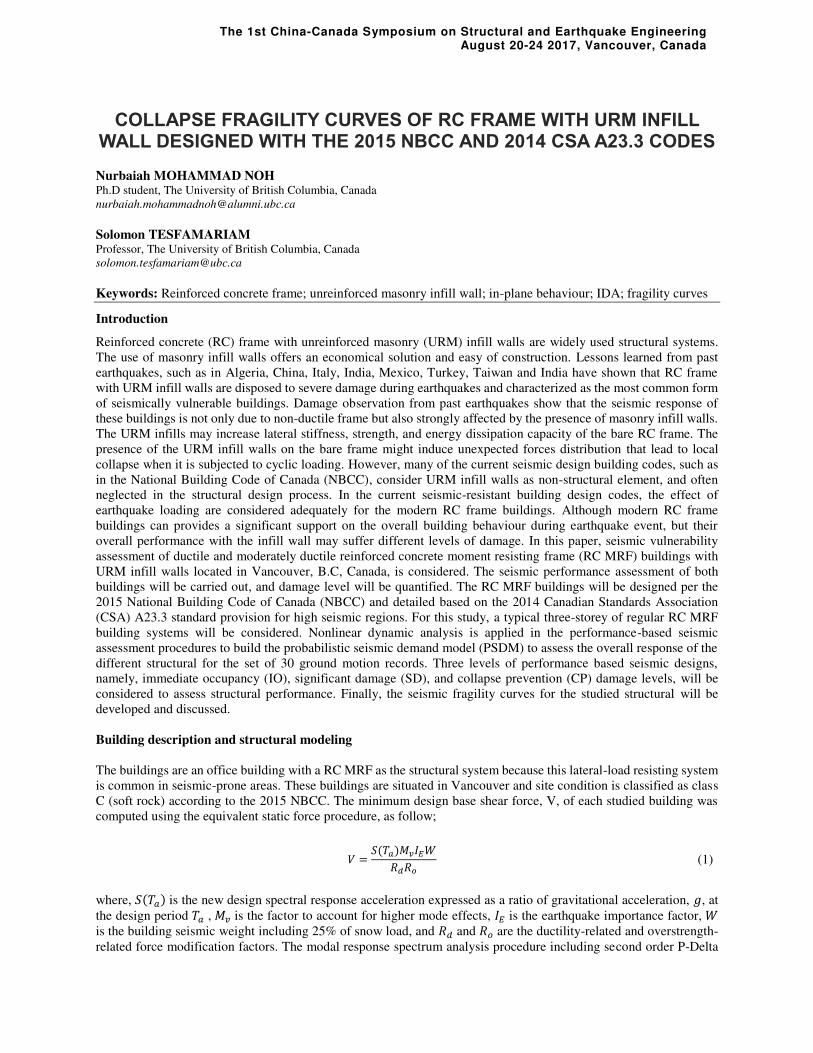
effects is considered in the design. The same floor plan is used at all levels as illustrated in Fig. 1(a). Typical super
imposed load values of 1.0 kN/m2, 0.5 kN/m2, 0.5 kN/m2 are used as partition, mechanical services, and roofing
material, respectively. The office floor live load was considered with 2.4 kN/m2 and snow load was 2.2 kN/m2. The
E-W moment resisting frame was chosen for the current study, as shown in Fig. 1(b). The RC frame office building
has 7-6 m bays in N-S direction and 3 bays in the E-W direction, which consists of 2- 9 m and a 6 m bay. The storey
height for each level is 3.65 m. The interior and exterior column are 500 × 500 mm and 450 × 450 mm, respectively.
The columns are assumed fixed at the base (ignoring soil structure interaction). The two-way slab floor system consists
of a slab 110 mm thick. The beams of both the N-S and E-W frames are 400 mm wide × 600 mm deep for first three
storeys and 400 mm × 550 mm for other storeys. The building is regular in plan and elevation.
Each of the RC MRFs with and without URM wall will be modeled as a two-dimensional frame models. The OpenSees
software will be used to calibrate and simulate the behavior of the buildings. The RC beams and columns will be
modeled by using lumped plasticity approach. Meanwhile, an equivalent diagonal strut at both direction will be
implemented to represent the in-plane behavior of the masonry infill walls. Stiffness degradation in loading and
unloading phases in the strut will be accounted using Pinching 4 Material. Nonlinear shear spring modeling approach
is considered to simulate the shear failure of columns induced by the URM wall effect. Figure 1(c) shows the
illustration of the modeling scheme of the masonry infilled RC frames. The properties of the models will be calibrated
with the experimental test result
Figure 1 Archetype code-conforming RC frame buildings; (a) Frame plan, (b) Frame elevation and nonlinear finite
element model of 3-storey RC MRF with full height masonry infill wall, and (c) infilled-frame model
Collapse performance assessment of buildings
The nonlinear incremental dynamic analysis (IDA) method will be conducted for the proposed models in order to
evaluate the seismic demand and capacity, and the collapse margin ratio of the RC buildings. In this analysis, the time-
history analysis will be repeated, using each far-field ground motion records scaled set, until the buildings collapse.
Finally, vulnerability (fragility) curves can be derived from the collapse data provided by the IDA through the
probability of structure collapse at a given ground motion intensity level. The results are presented on the global
response in terms of inter-storey drift, and the damage states. Preliminary results indicate that the performance of the
ductile frame is much better than that of the nominally ductile frame, and the level of deformation experienced by the
infilled frame are influenced by the characteristics of the RC members.
(a)
(b)
(c)

The 1st China-Canada Symposium on Structural and Earthquake Engineering August 20-24 2017, Vancouver, Canada
FUNDAMENTALS OF SEGMENTAL PRECAST POST-TENSIONED CONCRETE PIER
Qi Zhang Ph.D. Student, UBC Okanagan, Canada
M. Shahria Alam Associate Professor, UBC Okanagan, Canada
Keywords: Segmental; Precast Concrete; Prestress; Seismic Design; Bridges
In this presentation, equations of motion and finite element models of unbonded segmental post-
tensioned concrete pier are presented. The numerical expressions prove that the period of rocking
column changes in a free vibration, which cannot be simulated by a traditional single degree of
freedom system. In the finite element analysis, cyclic loadings are applied to the piers. A
parametric study and a regression analysis are carried out to propose basic design equations.
The 1st China-Canada Symposium on Structural and Earthquake Engineering August 20-24 2017, Vancouver, Canada
The seismic performance evaluation of earth retaining structures based on
probability density evolution method
Yu Huang College of Civil Engineering, Tongji University, China
Hongqiang Hu College of Civil Engineering, Tongji University, China
Keywords: earth retaining structure; dynamic reliability; stochastic vibration; PDEM; seismic performance;
Lots of earth retaining structures of slope have been damaged during the earthquake worldwide, which has caused
great loss of life and properties, and also lead to traffic interruption. Thus, it is necessary to evaluate the seismic
performance of earth retaining structure. Probability density evolution method (PDEM), a new methodology based
on stochastic vibration theory, was proposed to achieve this goal. It is a method that can combine the stochastic
dynamic analysis with current advance deterministic methods, and also can get the probability density function of
the parameters that we care about. The performance indexes and performance-based criteria are selected from the
standards and literatures. Tie-back wall, one kind of earth retaining structure was chosen to show the feasibility and
efficiency of the method. The deterministic seismic responses of tie-back wall were obtained by finite element
method. Then PDEM was used to get the stochastic responses and dynamic reliability. The seismic performance of
tie-back wall was evaluated by displacement-based criteria. This novel method can not only assess the seismic
performance of retaining structures based on stochastic vibration theory, giving more objective index than traditional
methods to evaluate, but also apply the performance-based concepts to earth retaining structures of slope.
The 1st China-Canada Symposium on Structural and Earthquake Engineering August 20-24 2017, Vancouver, Canada
NONLINEAR DYNAMIC ANALYSIS OF TIMBER CONCRETE HYBRID SYSTEM
Kuldeep Kaushik Graduate Student, Dept. of Civil Engineering, University of British Columbia, Vancouver, Canada.
Thomas Tannert Associate Professor, University of Northern British Columbia, Integrated Wood Design, Prince George, Canada.
Carlos E. Ventura Professor, Dept. of Civil Engineering, University of British Columbia, Vancouver, Canada.
Keywords: Hybrid system; Time history analysis; Pivot model; SAP2000; Nonlinear.
Introduction
Although timber is widely used as construction material in North America, it is limited to low-rise and mid-rise
construction for residential houses due to fire code restrictions. This limitation can be overcome by considering hybrid
systems which combine timber with other non-combustible materials for construction. This paper investigates the
feasibility of such a novel timber concrete hybrid system to increase the seismic force resistance, where a concrete
frame consisting of slabs at every third story provides the necessary stiffness and strength to resist gravity and lateral
loads. The intermediate stories including their floors, on the other hand, are constructed using light-frame wood
modules to create livable space. This novel structural approach reduces the environmental footprint of the building,
reduces the building weight and therefore the seismic demand on connections and foundation, and speeds up the
construction process.
Objectives
To understand the approach, an initial component level parametric study is carried out with a single bay single-story
model to investigate the failure and lateral load sharing mechanism between the concrete frame and the light wood
frame shear wall (LWFSW). This allows to design the elements of the hybrid system in an optimized way based on
the individual lateral load carrying capacity.
Furthermore, a system level analysis is done from the component level study where, 9,15 and 30 storey 2-Dimensional
hybrid frames are numerically modelled considering material nonlinearity and variation of infill timber shear panels
for the models. Nonlinear time history analysis is performed using 3 different ground motions to assess the structural
response in terms of inter story drift, base shear and failure mechanism and hence assessing the feasibility of such
hybrid structure
Procedure
A component level study of single storey single bay system is carried out to understand the failure mechanism of a
concrete moment frame with infill timber shear walls connected to the concrete frame by M14 bolts. The light wood
frame shear wall is calibrated with the experimental results of a 1.22m x1.22m and the M14 bolts results are taken
from experiments carried out at Tongji University. The nonlinearity in the concrete frame are modelled by hinges
designed as per ASCE 41. The system is pushed over to check the maximum capacity, the failure of the components
and the load sharing mechanism between the concrete frame and timber shear wall as shown in Fig 1 and Fig 2
respectively.

Page 2 of 2
Fig 1: Pushover analysis of the hybrid system with failure modes Fig 2: Load sharing mechanism of concrete and timber elements
A system level analysis is done based on the component level study and 2-D timber concrete frame are modelled
numerically by considering the scaled up nonlinear elements. Three different configurations of timber infill walls with
varying height are modeled numerically and nonlinear time history analysis is performed considering 3 ground
motions. The results are shown in fig 3 and 4 in terms of base shear and inter story drift respectively.
Results:
Fig 3: Inter story drift of 9,15 and 30 story structure under 3 ground motions
Fig 4: Base shear from nonlinear dynamic analysis of 9,15 and 30 story structures.
Conclusion
From the results, the hybrid system is feasible in terms of the measured criteria like base shear and interstory drift.
Also, the structures are more flexible with the variation in height. In terms of base shear, the nonlinear results are
underestimating the design values. As a future objective, 3-D models need to be numerically modeled to account for
torsion in structure, to give more realistic values.
The 1st China-Canada Symposium on Structural and Earthquake Engineering August 20-24 2017, Vancouver, Canada
SHAKING TABLE TEST ON LARGE-SCALE 4-STOREY TIMBER-STEEL HYBRID STRUCTURE
Qi Luo Ph.D. student, Tongji University
Hanlin Dong Ph.D. student, Tongji University
Zheng Li Assistant Professor
Minjuan He Professor
Keywords: Shaking table test; Timber-steel hybrid; Slotted-bolted friction damper; Multi-story building; Seismic
performance.
Wood is a significant building material for its renewability and sustainability, and its advantages is driving more
researchers’ attention. In order to utilize the benefit of wood, an innovative timber-steel hybrid structural system has
been proposed. In such structural system, the lateral resistance of the structure was provided by prefabricated infill
light wood shear wall and steel moment resisting frame. As previous research has investigated the lateral performance
of the timber-steel hybrid structure via monotonic and cyclic loading test, this test aims to acquire the real seismic
behavior to comprehensively evaluate the seismic performance of the timber-steel hybrid structure. In this study, the
test specimen was a 3-bay-by-1-bay scaled substructure of an office building assumed to be in Sichuan, one of the
seismic prone zones in China. The scaling factor of the specimen to prototype in dimension was SL=2/3. The test
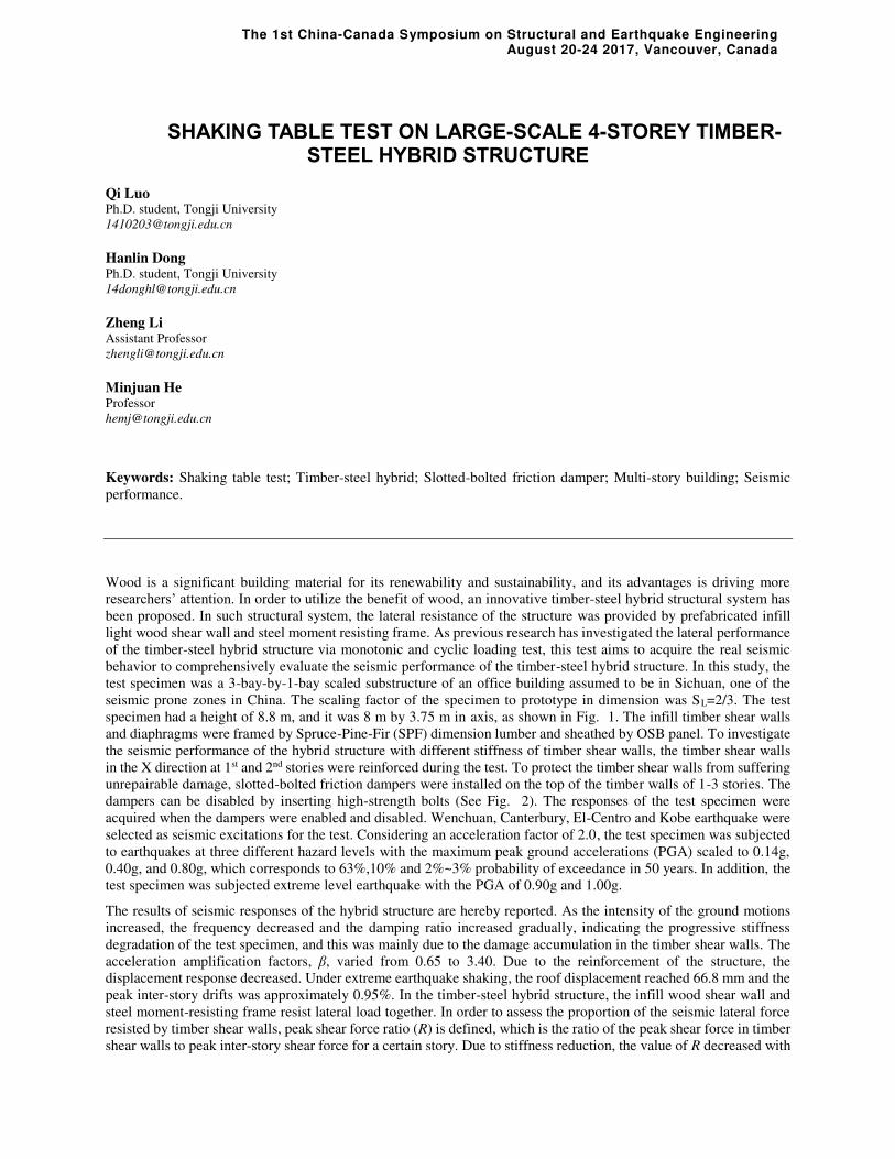
specimen had a height of 8.8 m, and it was 8 m by 3.75 m in axis, as shown in Fig. 1. The infill timber shear walls
and diaphragms were framed by Spruce-Pine-Fir (SPF) dimension lumber and sheathed by OSB panel. To investigate
the seismic performance of the hybrid structure with different stiffness of timber shear walls, the timber shear walls
in the X direction at 1st and 2nd stories were reinforced during the test. To protect the timber shear walls from suffering
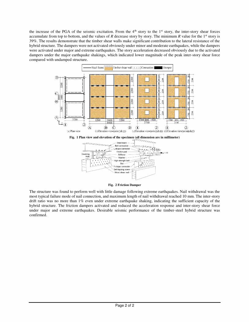
unrepairable damage, slotted-bolted friction dampers were installed on the top of the timber walls of 1-3 stories. The
dampers can be disabled by inserting high-strength bolts (See Fig. 2). The responses of the test specimen were
acquired when the dampers were enabled and disabled. Wenchuan, Canterbury, El-Centro and Kobe earthquake were
selected as seismic excitations for the test. Considering an acceleration factor of 2.0, the test specimen was subjected
to earthquakes at three different hazard levels with the maximum peak ground accelerations (PGA) scaled to 0.14g,
0.40g, and 0.80g, which corresponds to 63%,10% and 2%~3% probability of exceedance in 50 years. In addition, the
test specimen was subjected extreme level earthquake with the PGA of 0.90g and 1.00g.
The results of seismic responses of the hybrid structure are hereby reported. As the intensity of the ground motions
increased, the frequency decreased and the damping ratio increased gradually, indicating the progressive stiffness
degradation of the test specimen, and this was mainly due to the damage accumulation in the timber shear walls. The
acceleration amplification factors, β, varied from 0.65 to 3.40. Due to the reinforcement of the structure, the
displacement response decreased. Under extreme earthquake shaking, the roof displacement reached 66.8 mm and the
peak inter-story drifts was approximately 0.95%. In the timber-steel hybrid structure, the infill wood shear wall and
steel moment-resisting frame resist lateral load together. In order to assess the proportion of the seismic lateral force
resisted by timber shear walls, peak shear force ratio (R) is defined, which is the ratio of the peak shear force in timber
shear walls to peak inter-story shear force for a certain story. Due to stiffness reduction, the value of R decreased with
Page 2 of 2
the increase of the PGA of the seismic excitation. From the 4th story to the 1st story, the inter-story shear forces
accumulate from top to bottom, and the values of R decrease story by story. The minimum R value for the 1st story is
39%. The results demonstrate that the timber shear walls make significant contribution to the lateral resistance of the
hybrid structure. The dampers were not activated obviously under minor and moderate earthquakes, while the dampers
were activated under major and extreme earthquakes. The story acceleration decreased obviously due to the activated
dampers under the major earthquake shakings, which indicated lower magnitude of the peak inter-story shear force
compared with undamped structure.
Fig. 1 Plan view and elevation of the specimen (all dimension are in millimeter)
Fig. 2 Friction Damper
The structure was found to perform well with little damage following extreme earthquakes. Nail withdrawal was the
most typical failure mode of nail connection, and maximum length of nail withdrawal reached 10 mm. The inter-story
drift ratio was no more than 1% even under extreme earthquake shaking, indicating the sufficient capacity of the
hybrid structure. The friction dampers activated and reduced the acceleration response and inter-story shear force
under major and extreme earthquakes. Desirable seismic performance of the timber-steel hybrid structure was
confirmed.
The 1st China-Canada Symposium on Structural and Earthquake Engineering August 20-24 2017, Vancouver, Canada
NEW TECHNICS TO IMPROVE THE PERFORMANCE OF SELF-CENTERING BUCKLING-RESTRAINED BRACES
Qin Xie School of Civil Engineering, Southeast University, Nanjing, China, 210096. [email protected]
Keywords: SC-BRB; rubber end plate; friction fuse; initial stiffness; residual deformation.
Objectives
Although the existing self-centering buckling-restrained braces (SC-BRBs) have excellent self-centering capacity,
however, it is found that the initial stiffness of the brace is less than the theoretical value and the brace deformation
ability is small in the experiment. These problems can cause difficulties in the design of SC-BRB structures and limit
the application of the SC-BRBs. To improve the performance of the SC-BRBs, this paper propose two new technics,
including: the technic to improve the controllability of the initial stiffness-rubber end plate (Fig.1); the technic to
increase the deformation ability of the brace-friction fuse (Fig.2).
Fig.1 Concept of self-centering system with rubber end
plate Fig.2 Concept of SC-BRB with friction
Relevant Results
Three specimens were designed to verify the effectiveness of new technics. Table 1 gives the main design
parameters of the three specimens. The specimen SC-BRB-I didn’t use rubber end plate and friction fuse; the specimen
SC-BRB-II only applied rubber end plate with 1.9mm thickness rubber pad; the specimen SC-BRB-III applied both
friction fuse and rubber end plate with 3mm thickness rubber pad.
Table 1 The main design parameters of the specimens
Specimen No. Core plate Prestressed rod Pretension force Rubber pad thickness Friction fuse
SC-BRB-I 2×27mm×7.5mm 4φ14mm 180kN none none
SC-BRB-II 2×27mm×7.5mm 4φ14mm 180kN 1.9mm none
SC-BRB-III 2×27mm×7.5mm 4φ14mm 180kN 3mm with
Fig.3 shows the comparison of the experimental curve and theoretical curve of the specimen SC-BRB-I and the
specimen SC-BRB-II at the minimum displacement amplitude. The initial stiffness of the SC-BRB-II using the rubber
end plates is significantly closer to the theoretical value, which indicates that the rubber end plate has achieved the
intended target. Fig.4 shows the comparison of the experimental curve of the specimen SC-BRB-II and the specimen
SC-BRB-III at displacement amplitude less than 10.5mm. Increasing the thickness of the rubber pad will lead to an
F2
F2
F2
F2
F2
F2
Gap Gap
Gap Gap
Outer plate
Inner plate
F2
F2
Welding Outer tube Inner tube
Prestressed rods WeldingRubber pad
End plate
(a) Configuration of Self-centering system with rubber end plate
(b) In tension
(c) In compression
Main part of brace
(a) Configuration of SC-BRB with friction fuse
(b) Hysteretic curve of SC-BRB with friction fuse
F
u
ua
Fa
ur
Frictin fuse

Page 2 of 2
increase in the activation displacement of the self-centering system, resulting in an increase in the residual deformation
of the brace.
-2 -1 0 1 2
-400
-200
0
200
400
Forc
e(k
N)
Displacement(mm)
Experimental curve Theoretical curve
-1.5 -1.0 -0.5 0.0 0.5 1.0 1.5-400
-200
0
200
400
Forc
e(k
N)
Displacement(mm)
Experimental curve Theoretical curve
-15 -10 -5 0 5 10 15
-400
-200
0
200
400
Forc
e(k
N)
Displacement(mm)
SC-BRB-III
SC-BRB-II
(a) Specimen SC-BRB-I (b) Specimen SC-BRB-II Fig. 4 The experimental curve of
SC-BRB-II and SC-BRB-III at
displacement amplitude less than
10.5mm
Fig. 3 The experimental and theoretical curve of specimens at the
minimum displacement amplitude
Fig. 5(a) and Fig. 5(b) are the experimental hysteresis curves of the specimen SC-BRB-II and the specimen SC-
BRB-III when the displacement amplitude is greater than 18mm (the inter-story drift is 2%), respectively. The SC-
BRB-II could exhibit a stable self-centering performance when the displacement amplitude reaches 22.5mm (the inter-
drift story is 2.5%), and the average residual deformation is only 15.8% of the displacement amplitude. However, after
the prestressed rods is broken, the tensile and compressive bearing capacity would sharply drop from 608kN and -
618kN to 199kN and -208kN, decreased by 67.3% and 66.3%, while the average residual deformation may increase
to 90.1% of the displacement amplitude. The stiffness of SC-BRB-III decreased to zero when the friction fuse activated,
and the axial force is no longer increased. When the displacement amplitude reached 36mm (the inter-story drift is
4%), the average residual deformation of SC-BRB-III is 64.5% of the displacement amplitude. It indicates that the
friction fuse could avoid the fracture of the prestressed rods under the large deformation of the SC-BRB. Compared
with the condition of the prestressed rods is broken, the residual deformation of the SC-BRB with the friction fuse
could be effectively controlled.
-30 -20 -10 0 10 20 30
-750
-500
-250
0
250
500
750 SC-BRB-I
(18-27mm)
Fo
rce(
kN
)
Displacement(mm)
Prestressed rod fracture
-40 -30 -20 -10 0 10 20 30 40-750
-500
-250
0
250
500
750
Forc
e(k
N)
Displacement(mm)
SC-BRB-III
(18-35mm)
First activation of friction fuse
(a) Specimen SC-BRB-II (b) Specimen SC-BRB-III
Fig. 5 The experimental curve of specimens at the displacement amplitude larger than 18mm
Conclusions
1. The rubber end plate could effectively reduce the influence of the tube length tolerance to the initial stiffness of
SC-BRBs. However, the increase of the thickness of the rubber pad will increase of the activation displacement of the
self-centering system, resulting in an increase in the residual deformation of the SC-BRBs.
2. The fracture of prestressed rods may sharply decrease the axial bearing capacity of the SC-BRBs, which may
also increase the residual deformation to 90% of the displacement amplitude.
3. The friction fuse could avoid the fracture of prestressed rods under the large deformation of the SC-BRB. The
residual deformation of the SC-BRB with the friction fuse could be effectively controlled.

The 1st China-Canada Symposium on Structural and Earthquake Engineering August 20-24 2017, Vancouver, Canada
A REVIEW ON THE FATIGUE PERFORMANCE OF CFRP STRENGTHENED STEEL STRUCTURE
Anbang Li School of Civil Engineering, Xi’an University of Architecture & Technology, Xi’an 710055, China
Shanhua Xu School of Civil Engineering, Xi’an University of Architecture & Technology, Xi’an 710055, China
Keywords: Carbon fiber-reinforced polymer; strengthening steel structures; fatigue performance; bond behavior; environmental conditions
Abstract:Carbon fiber-reinforced polymer (CFRP) composites have been applied in architectural and civil
engineering successfully as another artificial structural material after metal and concrete. The CFRP strengthened
steel structure system have been widely studied and applied in recent years because of the significant advantages of
CFRP which include high strength/weight ratio, excellent fatigue and corrosion resistance, and good construction
performance. This paper presents a review on the fatigue performance of CFRP strengthened steel structure, three topics included in this review were exactly discussed and concluded: 1) effect of fatigue loading on the bond
behavior of CFRP composites bonded over steel; 2) fatigue performance of CFRP strengthened steel plate, steel
girder and welded joint; 3) effect of environmental conditions on the fatigue performance of CFRP strengthened
steel structure. Finally, the future research directions were prospected.

The 1st China-Canada Symposium on Structural and Earthquake Engineering August 20-24 2017, Vancouver, Canada
SEISMIC BEHAVIOR OF ROOF JOINTS WITH LOOSE HOLES IN SPACIAL STRUCTURES
Hongtao LIU Master Student, Dalian University of Technology, China
Yao CUI Associate Professor, Dalian University of Technology, China
Satoshi YAMADA Professor, Tokyo Institute of Technology, Japan
Keywords: anchor hole; roof joint; seismic behavior; finite element analysis
Objectives
Failure of roof joints between RC frames and steel roof were observed in spacial structures. Two types of bolt holes,
regular circular hole and loose hole are often used in roof joints. The roof joint with loose hole can release the
temperature stress and the horizontal displacements of the roof joint. We focused on the effect of anchor holes on the
seismic behavior of roof joint. Based on a series of FEM analysis, the resistance mechanism of anchor rods in the roof
joint with loose holes and the seismic behavior of the roof joint with loose holes are discussed.
(b) Circular hole
(a) Front view (c) Loose hole
Fig. 1 Dimensions of specimen Fig. 2 FEM model of specimen
The dimensions of the numerical model is shown in Figure 1. Two types of bolt holes, regular circular hole and loose
hole are considered. The detailed dimensions of bolt holes are shown in Fig. 1b and Fig. 1c. Considering about the
symmetric and boundary condition of the model, half of the specimen is simulated in the FEM model. Figure 2 showed
the basic information of the numerical model, in which the load jig was simplified by a reference point A by
considering the loading height of 230mm. Compressive axial load was applied on the reference point A, cyclic lateral
load was applied at point A by displacement control. Displacement in the X axis direction of all nodes for the RC
column, mortar and load plate (surface YOZ) were restrained for the symmetry. The nodes of bottom of RC column
(surface XOZ) were fixed. Six models were studied to investigate the effect of axial load and the type of bolt hole.
Results
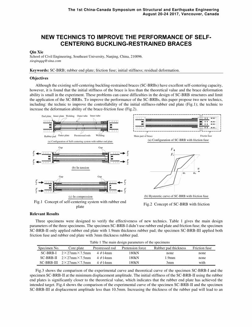
The lateral load-displacement curves of the six specimens are shown in Fig. 3. It is noted that the shear resistance are
increased as the axial load increased, and the hysteresis curve is fatter as the axial load increased. When the bolt hole
1850
60
0
525 800 525
80
02
30
43
0
10
30
Φ30
Load jig
Base plate
Mortar layer
Anchor rod
Φ32
80 80190
35
0
Anchor rod
Base plateMortar layer
Concrete
Stub
Loading
direction
X
O
Y
Z
A230
mm
35
0
80 80190
60 60
Page 2 of 2
is changed from circular holes to loose holes, the shear resistance is reduced. It is noted that Model ‘230-100-L’ showed clear slip behavior, while the other two model with axial force of 500 kN and 1000 kN did not exhibit the slip
behavior. Table 1 shows the shear resistance of roof joints with different types of bolt holes and vertical loads.
a. Fn=100kN b. Fn=500kN c. Fn=1000kN
Fig. 3 Load-displacement curve in cyclic loading
Table 1. Test result
Model name Loading
height/mm
Vertical
load/kN Bolt hole
Shear resistance/kN Horizontal
friction/kN Positive Negative
230-100
230
100 circular hole 292.03 -293.12 40.00
230-500 500 circular hole 430.36 -426.93 200.00
230-1000 1000 circular hole 486.46 -477.99 400.00
230-100-L 100 loose hole 246.48 -178.69 40.00
230-500-L 500 loose hole 277.46 -317.02 200.00
230-1000-L 1000 loose hole 363.05 -357.56 400.00
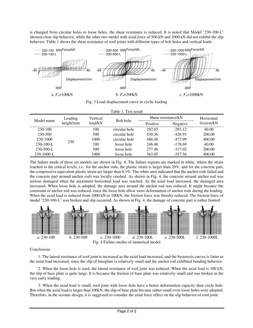
The failure mode of these six models are shown in Fig. 4. The failure regions are marked in white, where the strain
reached to the critical levels, i.e., for the anchor rods, the plastic strain is larger than 20%; and for the concrete part,
the compressive equivalent plastic strain are larger than 0.3%. The white area indicated that the anchor rods failed and
the concrete part around anchor rods was locally crushed. As shown in Fig. 4, the concrete around anchor rod was
serious damaged when the maximum horizontal load was reached. As the axial load increased, the damaged area
increased. When loose hole is adopted, the damage area around the anchor rod was reduced. It might because the
constraint of anchor rod was reduced, since the loose hole allow more deformation of anchor rods during the loading.
When the axial load is reduced from 1000 kN to 100kN, the friction force was thereby reduced. The friction force of
model ‘230-100-L’ was broken and slip occurred. As shown in Fig. 4, the damage of concrete part is rather limited.
a. 230-100 b. 230-500 c. 230-1000 d. 230-100L e. 230-500L f. 230-1000L
Fig. 4 Failure modes of numerical model
Conclusions
1. The lateral resistance of roof joint is increased as the axial load increased, and the hysteresis curves is fatter as
the axial load increased, since the slip of baseplate is relatively small and the anchor rod exhibited bending behavior.
2. When the loose hole is used, the lateral resistance of roof joint was reduced. When the axial load is 100 kN,
the slip of base plate is quite large. It is because the friction of base plate was relatively small and was broken in the
very early loading.
3. When the axial load is small, roof joint with loose hole have a better deformation capacity than circle hole.
But when the axial load is larger than 100kN, the slip of base plate became rather small even loose holes were adopted.
Therefore, in the seismic design, it is suggested to consider the axial force effect on the slip behavior of roof joint.
-40 40
-600
600
Displacement/mm
230-100 230-100-L
Force/kN
-40 40
-600
600
Displacement/mm
230-500 230-500-L
Force/kN
-40 40
-600
600
Displacement/mm
230-1000 230-1000-L
Force/kN

The 1st China-Canada Symposium on Structural and Earthquake EngineeringAugust 20-24 2017, Vancouver, Canada
SEISMIC BEHAVIOR OF SELF-CENTERING FRAMES WITHOUT FLOOR ELONGATION
Xiaogang Huang PhD candidate, Southeast University, China [email protected]
Zhen Zhou Professor, Southeast University, China [email protected]
Keywords: Self-centering coupled-beams (SC-CBs); Friction energy dissipation; Earthquake; Steel structures; Cyclic loading;
Objectives:
The common characteristic of self-centering (SC) posttensioned (PT) connections is the gap opening and closing at the beam-column interface, which often face the problem of deformation incompatibility with floor system and cause severe damage of floor slab. To address this drawback of PT frame expansion, an innovative friction-damped self-centering (SC) coupled-beams (CBs) that incorporate PT strands to provide a SC capacity along with friction devices (FDs) to dissipate energy is presented. The self-centering (SC) coupled beam (CB) is an innovative system that can avoid floor elongation. The internal force distribution of SC-CBs is also different with conventional posttensioned (PT) connections. Detailed three-dimensional finite element models (FEMs) of a single-story single-bay frame using SC-CBs are developed with consideration of different FDs installation positions.
Relevant Results:
As shown in Fig. 1, SC-CBs consist of two coupled components (upper component and lower component) compressed together by PT strands. The fabrication and pre-stress process of SC-CBs can be completed in the factory. The gap-opening behaviour of SC-CBs happens at the corresponding bottom beam flange location and would not cause floor elongation. By comparing the conceptual diaphragm of conventional PT connections and SC-CBs in Fig. 1, the gap mechanism of SC-CBs is achieved by introducing additional stocky pin connections and tubes locating below the W-section. The special configurations will increase steel consumption of the beams. However, the actual economic cost of two systems in structural engineering should be rigorously estimated considering the advantages and disadvantages associated with on-site labor cost, pretension construction difficulties and the feasibility of composite floor diaphragm.
Fig. 1. Assembly of SC-CB
The structural geometry configuration of the FEM is based on a benchmark building. Structural details included in the model simulate the actual construction requirements. As shown in Fig. 2, two similar FEMs are created except for differences in the installation location of the FDs. The solid model built by the ABAQUS program consist of columns, guiding elements, pin-connected members, reinforcing plates, shim plates, FDs, PT strands, and end plates in accordance with the structural sizes and actual assembly locations. However, the pin-to-hole clearance due to initial

Page 2 of 2
misalignment is not considered in the finite element analysis because this process often causes convergence difficulties of such models.
Fig.2. Schematic of the frame using SC-CBs (a) FDs at the two sides of tubes (b) FDs at the bottom of tubes
Figs. 3 show the global load–drift response of the frame, and the figure presents a stable flag-shape hysteresis that illustrates the energy dissipation capacity offered by the FDs and the SC behaviour created by the PT strands. The global behaviour results of the frames suggest that SC-CBs are a potential alternative to conventional PT beam-to-column connections in seismic regions, considering its attractive property that can avoid the PT boundary frame expansion. The unloading stiffness of the frame when FDs at the sides of concentric tubes is steep similar to the initial stiffness. This is due to all bolts in the FDs are subjected to pure axial friction and sliding in the FDs occurs simultaneously as the gaps between concentric tubes open.
-3 -2 -1 0 1 2 3
-150
-100
-50
0
50
100
150
Story Drift %
Late
ral L
oad/
kN
-3 -2 -1 0 1 2 3
-150
-100
-50
0
50
100
150
Story Drift %
Late
ral L
oad/
kN
Fig.3. Response of frame using SC-CBs (a) FDs at the two sides of tubes (b) FDs at the bottom of tubes
Conclusions:
Based on the three-dimensional FEM models with consideration of structural details and contact interactions, SC-CBs with two installation locations of the FDs are analysed, indicating that MRF using SC-CBs has good deformation capacity and SC behaviour under cyclic loading. The FD installation locations have an obvious effect on the unloading stiffness of the frame.

The 1st China-Canada Symposium on Structural and Earthquake Engineering August 20-24 2017, Vancouver, Canada
EXPERIMENTAL STUDY ON HYSTERESIS PERFORMANCE OF BUCKLING-RESTRAINED BRACE WITH NORMAL GRADE STEEL CORE
Ruyue Liu (Time New Roman 10, bold –Format: Authors Names) Ph.D, Xi’an University of Architecture and Technology, Shaanxi, China Emai:[email protected]
Yong Yang Professor, Xi’an University of Architecture and Technology, Shaanxi, China Email:[email protected]
Keywords: buckling-restrained brace; normal grade steel core; hysteresis performance; energy dissipation capacity; experimental research.
Buckling-restrained brace is a kind of special steel braces, which is composed of core steel and outer confining segment, and it could be used in the energy-dissipation design of steel structure to enhance the seismic performance of structures. Recently, the researches and applications of BRBs became attractive to many researchers from different countries. BRB was called as Unbounded Brace in Japan. The earliest research initiated from the Ylshino’s research of steel plate cast with concrete panel peripherally in 1971[1]. In 1973, Wakabayashi et al conducted innovative research of BRB(hidden steel brace) and proposed that steel brace acting as the core part of BRB should be ensured to sustain axial force only along with peripheral buckling constraints[2] unit constraining the steel braces, and yielded under both under tension and compression by means of yield-constraint segment.
Some studies involved with different aspects of BRBs were conducted. The best type of constraint unit which was essential to the unbuckling behavior under compression was determined through comparative trials by Chen C. C.[6] et al; the study of unbounded material, which was important to reduce the interaction between the core steel and the constraint segment, was carried out by Cai K.Q. et al; the theoretical analysis of BRB including the global stability and local stability as well as design method was performed by Liu J.B. and Tian J.; the design method of stability of BRB was proposed by Li Yan and Zhao Jun et al after the research on structural scheme by experiment and method of FEM [7,9]; The criterion of the strength and rigidity design of BRB was put forward by Xie Q.; a series of performance tests of BRB in full scale was conducted by Ye L.P. and then the design methods were summarized.
In order to reduce the cost of buckling-restrained brace (BRB) product, steel core of normal strength grade was more and more used in China. In this research, normal hot-rolled steel of Q235 grade of Chinese standard was used to produce a series of buckling-restrained brace (BRB), and six specimens were tested to figure out their hysteresis performance. In the experiment, a special test setup was adopted, which was proved very effective. And the influences of some key parameters such as the cross-section size, the strength of steel core as well as the type of outside irrigated material was also fully studied. All the six specimens were tested under quasi-static experimental setup, which was loaded reversal and cyclically. Besides, the problems in centring of new type BRB which existed in experiment was settled through the improvement of loading device and the best material configuration to achieve the best combination of performance and economy was navigated by changing the strength of core material and fill material.
Based on the experimental results, the hysteresis performances of such kind BRBs were fully investigated. From the above, it was concluded that the design of this new type BRB was applicable and reliable, and the hysteresis performance of the specimens was stable and good enough to meet the codes requirements. 2. Experiment result
It was found that every hysteresis curve was very plump with good energy dissipating performance and it reached plastic state at compression area, having similar hysteresis performance at both tension and compression area, achieving that purpose of buckling-restraint. Meanwhile, by comparison, it could also be found that fill material had obvious effect on BRB’s energy dissipating performance and using high strength mortar owned higher performance, better than C25 concrete. Besides, it could be seen that energy dissipating performance of specimen with higher strength of fill material was superior to that with lower strength and the deformation performance was better.
The ultimate capacity of core material was compared with the ultimate tensile force and compress force obtained by experiment, and the ultimate capacity was gain by the multiply of material yielding strength and the least cross size

Page 2 of 2
area of core material. According to relative standards, the ratio of ultimate tensile force to ultimate capacity and the ratio of ultimate compress force to ultimate was not more than 1.1, respectively.
3. Conclusions 1)Improving the strength of fill material in steel tube can improve the energy dissipating performance of member
largely and enhance the elastic-plastic deformation ability of member. 2)Increase of size area of core material can remarkably improve the seismic performance of member. 3)Through the analysis on hysteresis curve of 6 specimen, it indicates that with the increase of size area of
material, every performance index enhances remarkably. 4)From the experiment, it can be found that all specimens do not buckled during the process and that reach the
envisage of “buckling-restrained” at the BRB design.
a-QYF200 × 2300-A1; b- QYF275 × 2300-A1; c- QYF245 × 2300-A1; d- QYF200 × 2300-A2; e- QYF275 × 2300-A2; f- QYF245 × 2300-A2;
Fig.1 Curve of axial load-displacement of specimens
P/kN
Δ/mm
P/kN
Δ/mm
P/kN
Δ/mm
P/kN
Δ/mm
P/kN
P/kN
Δ/mm Δ/mm
The 1st China-Canada Symposium on Structural and Earthquake Engineering August 20-24 2017, Vancouver, Canada
COLLAPSE ASSESSMENT OF THE RC BRIDGES USING PERFORMANCE-BASED DESIGN APPROACH INCLUDING SSI
Kianosh Ashkani Zadeh PhD Candidate, Department of Civil Engineering, The University of British Columbia, Vancouver, BC, Canada
Carlos Ventura Professor, Department of Civil Engineering, The University of British Columbia, Vancouver, BC, Canada
Keywords: RC Bridges, Performance-Based Design, Soil Structure Interaction (SSI), Probability of Collapse,
Collapse Margin Ratio (CMR)
Effect of supporting soil can have a significant effect on response of structures subjected to strong earthquake.
Despite of its major effect, soil-structure interaction (SSI) is not sufficiently addressed in current design code and
practice. This is due to excessive complexity and uncertainties that arise from including SSI effects.
In this research, the effect of soil-structure interaction on the behaviour of RC bridges will be studied within
the framework of performance-based earthquake engineering. The SSI effect is simulated using continuum and
discrete representation of soil. Non-linear Incremental Dynamic Analysis (IDA) along with the approach of simulated
and non-simulated collapse modes will be employed to predict the fragility curves for SSI-Discrete and SSI-
Continuum models. Continuum simulation of soil in SSI-Continuum model provides a more realistic physical
representation of the soil. Whereas the discrete simulation (SSI-Discrete) offers a simplified methodology suitable for
engineering practice.
Relative displacement and drift of the abutment back walls and pier columns will be considered as
Engineering Demand Parameters (EDPs) and spectral acceleration of ground motions will be chosen as the Intensity
Measure (IM). Collapse Margin Ratio (CMR) which is a characteristic measure of collapse safety of the structure will
be chosen to objectively compare the response of SSI-Discrete and SSI-Continuum models at the collapse level.
The outcomes of this research will offer an insight into the response of bridge-soil system subjected to severe
earthquake loading. Ultimately, a methodology will be developed to allow designers to adjust the SSI-Discrete
fragility curves to reflect the SSI-Continuum effects. When implemented in design codes, designers will be able to
better estimate the effect of SSI without the need to perform complex SSI-Continuum simulations.
The 1st China-Canada Symposium on Structural and Earthquake Engineering August 20-24 2017, Vancouver, Canada
DEVELOPMENT OF STRUCTURAL DEBRIS FLOW FRAGILITY CURVES USING THE MOMENTUM FLUX AS A HAZARD PARAMETER
Jorge A. Prieto Department of civil engineering, EAFIT University, Medellin, Colombia
Murray Journeay Natural Resources Canada, Vancouver, Canada
Ana B. Acevedo Department of civil engineering, EAFIT University, Medellin, Colombia.
Juan D. Arbelaez Department of civil engineering, EAFIT University, Medellin, Colombia.
Malaika Ulmi Natural Resources Canada, Vancouver, Canada
Keywords: Debris flow fragility curves, debris flow vulnerability, moment flux, flow hazard, debris flow losses
The intent of this work is to present a method for developing fragility curves for assessment of risk linked to global
structural damage in buildings due to debris flows using the flux momentum as a hazard parameter. No analysis of
individual components of buildings are considered but general global effects of building damage using the interaction
between hydrodynamic forces and equivalent horizontal forces, push-over curves, are presented.
Debris flows produce hydrodynamic forces over buildings, which are a function of flow density, velocity and structure
geometry. Those forces can be expressed in terms of the flux momentum, which involves flow height and velocity.
Fragility curves that are expressed in terms of flux momentum as the hazard parameter are developed here.
Following the same framework developed for the tsunami HAZUS model, the approach used here is to equate forces
due to debris flow demand to the lateral capacity of a building. The main debris flow forces considered are the
hydrodynamic forces, i.e. the drag force, and the impulsive force. The latter one is included in a simplified way using
a coefficient, Kd, so the lateral debris flow force, FDF, acting on a building can be expressed in terms of the drag
force. 𝐹𝐷𝐹 = 𝐾𝑑 0.5𝜌 𝑑 ℎ𝑣 (1)
Where is the density of the debris flow materials, Cd is the drag coefficient, B is the building plan dimension normal
to flow direction, and ℎ𝑣 is the maximum momentum flux (flow depth times velocity squared).
The lateral capacity of a building is given by F = 𝛼 𝑊 (2)
It is now straightforward to equate debris flow force, equation (1), with lateral building capacity, equation (2) and
solve for the momentum flux term, ℎ𝑣 , to obtain:
Page 2 of 2
ℎ𝑣 = 2𝛼𝐾𝑑𝜌 𝑑 𝑊
We can divide the capacity curve of the building in two points, the initial point is the yield force at the base of the
building the second point is the ultimate force of the building. Given these points, it is possible to relate damage to
force using the capacity curve (pushover). Complete damage to the structure occurs when the debris flow force is
equal to the ultimate force, Fu, of the model building type of interest. Extensive damage to the structure occurs when
the debris flow force is equal to the force corresponding to the average of the yield and ultimate force, (Fy + Fu)/2, of
the building type of interest. Moderate damage to the structure occurs when the debris flow force is equal to the yield,
Fy, force of the model building type of interest.
Fragility curves provide the conditional probability of reaching or exceeding a damage state or condition given a
hazard parameter. The probability of being in a specific damage state is easily calculated as the difference of the values
given by two consecutive damage state fragility curves at the hazard level. The expected loss is then obtained as the
sum of the products of the probabilities of being in each damage state times the corresponding mean loss for those
damage states.
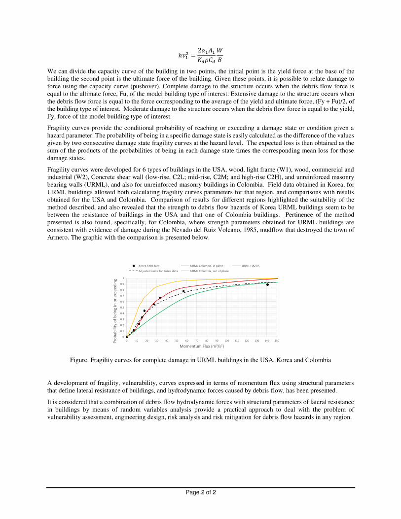
Fragility curves were developed for 6 types of buildings in the USA, wood, light frame (W1), wood, commercial and
industrial (W2), Concrete shear wall (low-rise, C2L; mid-rise, C2M; and high-rise C2H), and unreinforced masonry
bearing walls (URML), and also for unreinforced masonry buildings in Colombia. Field data obtained in Korea, for
URML buildings allowed both calculating fragility curves parameters for that region, and comparisons with results
obtained for the USA and Colombia. Comparison of results for different regions highlighted the suitability of the
method described, and also revealed that the strength to debris flow hazards of Korea URML buildings seem to be
between the resistance of buildings in the USA and that one of Colombia buildings. Pertinence of the method
presented is also found, specifically, for Colombia, where strength parameters obtained for URML buildings are
consistent with evidence of damage during the Nevado del Ruiz Volcano, 1985, mudflow that destroyed the town of
Armero. The graphic with the comparison is presented below.
Figure. Fragility curves for complete damage in URML buildings in the USA, Korea and Colombia
A development of fragility, vulnerability, curves expressed in terms of momentum flux using structural parameters
that define lateral resistance of buildings, and hydrodynamic forces caused by debris flow, has been presented.
It is considered that a combination of debris flow hydrodynamic forces with structural parameters of lateral resistance
in buildings by means of random variables analysis provide a practical approach to deal with the problem of
vulnerability assessment, engineering design, risk analysis and risk mitigation for debris flow hazards in any region.
00.10.20.30.40.50.60.70.80.910 10 20 30 40 50 60 70 80 90 100 110 120 130 140 150Probability of being in or
exceeding
Momentum Flux (m3/s2) Korea field data URML Colombia, in plane URML HAZUSAdjusted curve for Korea data URML Colombia, out of plane
The 1st China-Canada Symposium on Structural and Earthquake Engineering August 20-24 2017, Vancouver, Canada
SELF-CENTERING BEHAVIOR OF POST-TENSIONED STEEL BEAM COLUMN CONNECTIONS UNDER SEISMIC LOADING
Md Arman Chowdhury MASc Student, the University of British Columbia, Canada
Ahmad Rahmzadeh PhD Student, the University of British Columbia, Canada
M. Shahria Alam Associate Professor, the University of British Columbia, Canada
Keywords: Self-centering connection, shape memory alloy (SMA), post tensioned connection.
The use of post-tensioning strands is now a proven technique to enhance the seismic performance of moment resisting
frames. As opposed to conventional moment connections, in which structural components are bonded to each other,
in post-tensioned connections they are pre-compressed together, allowing the formation of gap under lateral loads.
Such a configuration provides a connection with adequate stiffness, strength, and ductility while it removes residual
deformations by returning to its plumb position after load removal. Previous studies have shown that steel dissipators
undergo large plastic strains and should be replaced after being exerted to an earthquake. Moreover, post-tensioned
systems lose their re-centering feature when the post-tensioning strands yield at large drifts. To overcome the
aforementioned drawbacks, this paper evaluates the application of shape memory alloys (SMA) as both energy
dissipating elements and partial strands in a post-tensioned steel beam-column connection. First, finite element (FE)
models of previously tested specimens are developed and validated against test results. Then, parametric studies are
conducted to investigate the cyclic behavior of SMA energy dissipators. Various types of superelastic SMAs including
iron, copper and nitinol based alloys are considered. As another application, the steel strands are partially replaced by
SMA strands to assess the performance of the connection in terms of self-centering capability. The results indicate
that the use of SMA benefits the connection by eliminating replacement costs of steel dissipaters after the earthquake;
however, at the expense of reduction in the dissipated energy. The use of partially replaced SMA strands improves
the self-centering capability, while other properties remain the same, as steel strands.The extended abstract is limited
to a maximum of TWO pages including all elements, such as text, tables and figures. In other words, the word
document should not exceed two pages.
The 1st China-Canada Symposium on Structural and Earthquake Engineering August 20-24 2017, Vancouver, Canada
STUDY ON SEISMIC PERFORMANCE OF RETRACTABLE ROOF
Peng GE Graduate student, Tongji University, China
Haibei XIONG Professor, Tongji University, China
Keywords: Retractable roof, Temporary construction module, Seismic design, Mode-superposition response
spectrum method, Time history menthod
The reactor building of the AP/CAP series nuclear power plant is constructed with top open. So a retractable roof that
serves as temporary construction module and has little influence on the construction procedure is needed to protect
the nuclear power plant. This paper focus on the study of seismic performance of the retractable roof. The value of
using the temporary construction module is demonstrated and several preliminary plans are designed under the
typhoon wind load where the fundamental wind pressure is 2.25 kN/m2. Then the optimal one is selected. The
fundamental status of the retractable roof is determined regardless of the operation status. The seismic performance
under the frequent and fortification earthquake is evaluated using mode-superposition response spectrum method. The
seismic performance under three seismic waves with different characteristic with the peak ground acceleration is
1m/s2 is evaluated and compared using time history method. The results show that the retractable roof has a good
capacity but the connection area of hydraulic machine is weak. The responses of retractable roof are different under
three seismic waves and the structure is most sensitive to Shanghai wave.