remnants of early hydraulic power systems · · 2009-11-01remnants of early hydraulic power...
TRANSCRIPT

3rd Australasian Engineering Heritage Conference 2009
Remnants of Early Hydraulic Power SystemsJ W Gibson MA (Syd), MIE Aust. & M C Pierce BE (Elec), FIE Aust.
SUMMARY: This paper briefly outlines the development of water hydraulic power systems and devices during the nineteenth century and then describes a range of extant system elements from Australia and New Zealand. The significance of this early motive power technology is underlined by the many end-use applications that evolved and further work in identifying, recording and where practicable, conserving extant remnants is advocated.
KEYWORDS: hydraulic, power, historic, heritage
1. THE DEVELOPMENT OF HYDRAULIC POWER
The first practical hydraulically operated machine was the hydraulic press, invented by Joseph Bramah in 1796. Bramah’s press embodied the principle originally demonstrated by Pascal in 1647, where-in fluid pressure created by applying a force to a small area plunger in a closed cylinder can be used to act on a larger area plunger to produce a correspondingly larger force if the fluid spaces in the two plunger cylinders are connected by a pipe. In Bramah’s machine the larger plunger or ram operated the moving platen of the press.
Bramah went on to conceive other ideas for transmitting and using hydraulic power, most notably as documented in his ‘omnibus’ patent specification of 1812, however these ideas were not taken up in his lifetime (McNeil 1968). It was not until 1840 that William Armstrong – later knighted for his pivotal work in improving armaments – developed his ideas for a hydraulically operated crane based on the hydraulic jigger. The hydraulic jigger comprised a ram in a closed cylinder arranged with multiple pulley sheaves at each end so as to multiply movement of the free end of a chain or rope wound around the sheaves when a pressurised fluid, normally water, was admitted into the cylinder. (The hydraulic jigger operated in the reverse manner to the conventional block and tackle).
A 5 ton (5t) hydraulically operated crane based on Armstrong’s design was installed on a Newcastle-on-Tyne wharf in 1846 (Armstrong 1858). Its success led to similar hydraulic cranes being installed for wharves and railway yards in other places in the UK. Figure 1 shows a diagram from Armstrong’s 1858 paper of an early hydraulic crane with hydraulic jiggers used for both the hoisting and slewing motions. The source of the pressurised fluid for these early hydraulic cranes was the town’s water supply. Water pressures of up to 90 psi (600 kPa) could be obtained in this way to act on the ram within the individual hydraulic jiggers, with control by way of lever operated three-way valves.
Figure 1. Armstrong Hydraulic Crane.
Although hydraulic cranes operated from the public water supply mains worked tolerably well, problems arose with pressure variations due to draw-off by other water users. Notwithstanding this, some installations continued to utilise mains pressure water sources, including some early hydraulic lifts. Armstrong’s first solution to the variable pressure difficulty was to arrange for an independent elevated tank or ‘water tower’ into which water was pumped and from which the hydraulic plant was then powered. In 1851 Armstrong is credited with reinvention of the hydraulic accumulator used in conjunction with high-pressure plunger pumps, a system originally proposed although not implemented by Bramah in 1812. In this device a ram arranged in a vertical closed cylinder is loaded by dead weight ballast, with energy able to be stored by upward movement of the ram and recovered on its descent. Thus, the accumulator acts as a pressure sustaining device between the high-pressure pumps and the hydraulically operated machines connected to the system. (Armstrong 1858; Armstrong 1877).
1
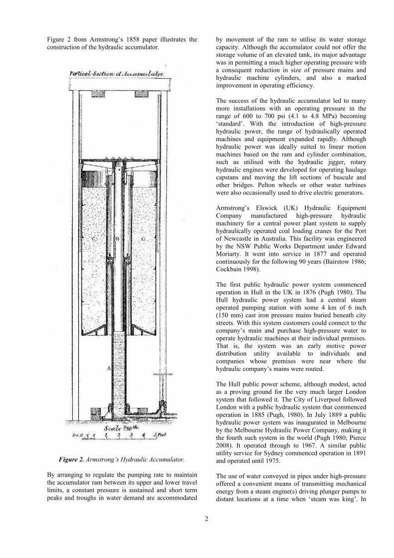
Figure 2 from Armstrong’s 1858 paper illustrates the construction of the hydraulic accumulator.
Figure 2. Armstrong’s Hydraulic Accumulator.
By arranging to regulate the pumping rate to maintain the accumulator ram between its upper and lower travel limits, a constant pressure is sustained and short term peaks and troughs in water demand are accommodated
by movement of the ram to utilise its water storage capacity. Although the accumulator could not offer the storage volume of an elevated tank, its major advantage was in permitting a much higher operating pressure with a consequent reduction in size of pressure mains and hydraulic machine cylinders, and also a marked improvement in operating efficiency. The success of the hydraulic accumulator led to many more installations with an operating pressure in the range of 600 to 700 psi (4.1 to 4.8 MPa) becoming ‘standard’. With the introduction of high-pressure hydraulic power, the range of hydraulically operated machines and equipment expanded rapidly. Although hydraulic power was ideally suited to linear motion machines based on the ram and cylinder combination, such as utilised with the hydraulic jigger, rotary hydraulic engines were developed for operating haulage capstans and moving the lift sections of bascule and other bridges. Pelton wheels or other water turbines were also occasionally used to drive electric generators.
Armstrong’s Elswick (UK) Hydraulic Equipment Company manufactured high-pressure hydraulic machinery for a central power plant system to supply hydraulically operated coal loading cranes for the Port of Newcastle in Australia. This facility was engineered by the NSW Public Works Department under Edward Moriarty. It went into service in 1877 and operated continuously for the following 90 years (Bairstow 1986; Cockbain 1998).
The first public hydraulic power system commenced operation in Hull in the UK in 1876 (Pugh 1980). The Hull hydraulic power system had a central steam operated pumping station with some 4 km of 6 inch (150 mm) cast iron pressure mains buried beneath city streets. With this system customers could connect to the company’s main and purchase high-pressure water to operate hydraulic machines at their individual premises. That is, the system was an early motive power distribution utility available to individuals and companies whose premises were near where the hydraulic company’s mains were routed. The Hull public power scheme, although modest, acted as a proving ground for the very much larger London system that followed it. The City of Liverpool followed London with a public hydraulic system that commenced operation in 1885 (Pugh, 1980). In July 1889 a public hydraulic power system was inaugurated in Melbourne by the Melbourne Hydraulic Power Company, making it the fourth such system in the world (Pugh 1980; Pierce 2008). It operated through to 1967. A similar public utility service for Sydney commenced operation in 1891 and operated until 1975.
The use of water conveyed in pipes under high-pressure offered a convenient means of transmitting mechanical energy from a steam engine(s) driving plunger pumps to distant locations at a time when ‘steam was king’. In
2

this way, motive power could be delivered to end-use devices at distances of up to 10km with an efficiency of around 90% (Pugh 1980). A central pumping plant could be arranged to power many distributed end-use devices within an industrial site such as docks, railway workshops, etc, or in a city context where the high-pressure mains were laid under the streets, for powering passenger lifts in tall buildings. As well as convenience and an ‘economy of scale’ by using large central plant, the atmospheric polluting effect of a multiplicity of small steam boiler plants could be reduced along with avoiding the cost to operate and maintain each such installation. These latter considerations were particularly pertinent for the public hydraulic power utilities serving urban areas in the late 19th and early 20th centuries.
Figure 3 illustrates a distributed hydraulic power system with central plant consisting of a steam engine or other prime mover driving high-pressure pumps, a pressure sustaining and controlling device in the form of a hydraulic accumulator connecting, via HP piping, to a diverse range of end-use hydraulically operated machines and devices. In the following sections, each of these elements is discussed with examples of remnants from a range of locations that are known to the authors.
Figure 3. Typical Hydraulic Power System.
A more detailed diagram for the system is provided in Appendix A.
2. HIGH PRESSURE PUMPING PLANT
Two high-pressure pumps remain within the NSW Government Railways workshops, now Australian Technology Park, at Eveleigh in Sydney. They are located in a pump-house south of Bay 2 of the workshop buildings. One is a twin cylinder steam driven Fielding and Platt engine/pump, still in excellent condition – see Figure 4. The other is an electrically driven three-cylinder Hathorn pump. A pressure gauge on the wall suggests a red-line hydraulic pressure of 2500 psi (17 MPa). The Fielding and Platt steam engine pumping set is now a quite rare example of what was originally the norm for high-pressure hydraulic power system pumping plant with the plunger force pumps directly connected to the steam engine crossheads.
Figure 4. Fielding & Platt HP Pump.Chullora.
The use of water hydraulic power equipment in many heavy industrial facilities well into the twentieth century sometimes led to reciprocating steam engine high-pressure pump sets being replaced by electrically driven pumps, although in most cases the pumps themselves remained as multiple cylinder positive-displacement pumps as used by Armstrong from the 1850s. This appears to apply to the electric motor driven three-cylinder Hathorn pump at Eveleigh. For later installations, electrically driven pumps could have been employed from the outset. Electrically driven, three-cylinder positive displacement pumps for on-site hydraulic services remain extant at Sydney’s Garden Island Naval Stores building, Chullora NSW railway workshops and in the power house of the former dockyard on Cockatoo Island. Refer to Figure 5.
Figure 5. Electrically driven HP Pump, Chullora.
3
An independent hydraulic power system that served the wharves of Walsh Bay in Sydney utilised a twin cylinder double-acting reciprocating pump driven by a 65 HP (48 kW) electric motor. It still exists as a feature in a restaurant on ground level in the Central Wharf Stevedoring building (wharf 8/9). The system supplied hydraulic power to lifts, wool presses, and possibly to wharf conveyors.
Figure 6 shows a three-cylinder Johns & Waygood hydraulic pump set at the historic Hobart wool store – now an apartment hotel – were it is was most likely used to power water hydraulic wool baling presses. The pump has a pair of fast and loose pulleys for a flat belt drive from an engine, either directly or through a countershaft. The crankshaft for the three plunger type pumps is in turn driven through reduction spur gearing. The suction and delivery valves are mounted on the outward end of the pump cylinders with the interconnecting pipework terminating in a two-bolt oval flange characteristic of water hydraulic power systems.
Figure 6. Johns & Waygood HP Pump,Hobart.
3. HYDRAULIC ACCUMULATORS
Hydraulic accumulators, whilst all embodying the basic functional configuration used by Armstrong and illustrated diagrammatically in Figure 2, took on a variety of forms and construction details.
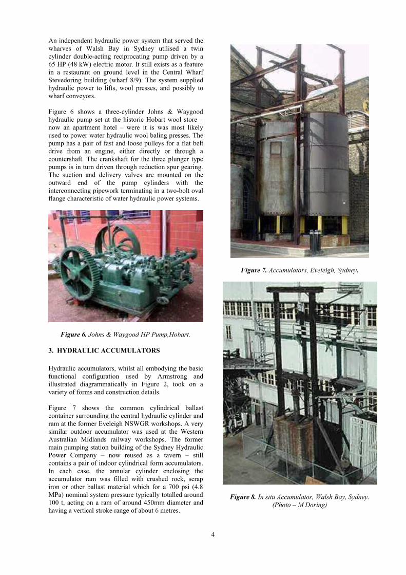
Figure 7 shows the common cylindrical ballast container surrounding the central hydraulic cylinder and ram at the former Eveleigh NSWGR workshops. A very similar outdoor accumulator was used at the Western Australian Midlands railway workshops. The former main pumping station building of the Sydney Hydraulic Power Company – now reused as a tavern – still contains a pair of indoor cylindrical form accumulators. In each case, the annular cylinder enclosing the accumulator ram was filled with crushed rock, scrap iron or other ballast material which for a 700 psi (4.8 MPa) nominal system pressure typically totalled around 100 t, acting on a ram of around 450mm diameter and having a vertical stroke range of about 6 metres.
Figure 7. Accumulators, Eveleigh, Sydney.
Figure 8. In situ Accumulator, Walsh Bay, Sydney. (Photo – M Doring)
4

The accumulator originally installed for the independent hydraulic power facility at Sydney’s Walsh Bay wharfs utilised a rectangular platen to support a brickwork ballast instead of the more usual cylindrical style. Figures 8 show this accumulator in its original location. It is currently in a new nearby location where it has been reconstructed and interpreted. The cylinder and the upper portion of the ram are clearly visible.
Yet another accumulator design is illustrated in Figure 9 near the Brakehead of the former Denniston Incline on the west coast of the South Island of New Zealand. It was reportedly used for the hydraulic crane that was once adjacent to the Top Brake and also for the hydraulic actuators on the coal bin discharge chutes (Petchey, 2007). (The photograph dates from 2005 and the item may have since been conserved as a part of the site rehabilitation works by the NZ Department of Conservation).
The position of the accumulator ram was normally used to control the high-pressure pumps to match the external water demand by the connected end-use equipment. In the case of a steam engine driven pump, a mechanical linkage from the accumulator ram could be used to continuously adjust the engine speed and thus the pumping rate in a form of proportional feedback control. For electrically driven pumps, a wound rotor induction motor was commonly used with limit switches operated by the accumulator ram movement arranged to switch ‘in’ or ‘out’ rotor circuit resistors and thus adjust the pumping rate in several discrete steps. The accumulator at Walsh Bay has the remnants of an electrical limit switch system.
Figure 9. Denniston Hydraulic Accumulator, NZ
For some large sites utilising water hydraulic power and for public utility systems, the high-pressure pumping plant and associated accumulators were housed in a purpose designed, and sometimes ornate, building. The former central plant building for the Newcastle (NSW) harbour hydraulic power system with its twin accumulator towers is now the sole readily visible remnant of this important maritime industrial
installation. The Sydney Hydraulic Power Company main pumping station building in Pier Street Darling harbour has also survived and has been recycled for another use as mentioned above.
4. HYDRAULIC HOISTS & CRANES
Hydraulic hoists and cranes typically used the ‘hydraulic jigger’ as developed in the UK by Armstrong for his first c1850 hydraulic crane. Another common use of a single hydraulic jigger was for goods hoists to lift materials to and from upstairs warehouse floors. These were commonly called ‘whips’.
Melbourne’s c1880 Rialto building – now a prestigious hotel – has two hydraulic jiggers mounted vertically on the west external wall. One of these is depicted in Figure 10. Wire rope, now removed, originally passed around the three upper and lower sheaves on the jigger. The free end then ran over a pulley in a pediment over the uppermost floor access doorway to the lifting hook. The two whips were powered from the Melbourne Hydraulic Power Company public supply mains and were used to lift goods from a basement level laneway to the access doorways on any of the upper floors (Pierce 2008). The Rialto building is heritage listed and the remnants of the whip hoists have been retained and preserved and, in recent times referred to in interpretive signage about the building. They are about the only readily visible reminders in Melbourne of the once dominant hydraulic motive power utility.
Figure 10. Rialto Building Hoist (Whip), Melbourne.
5
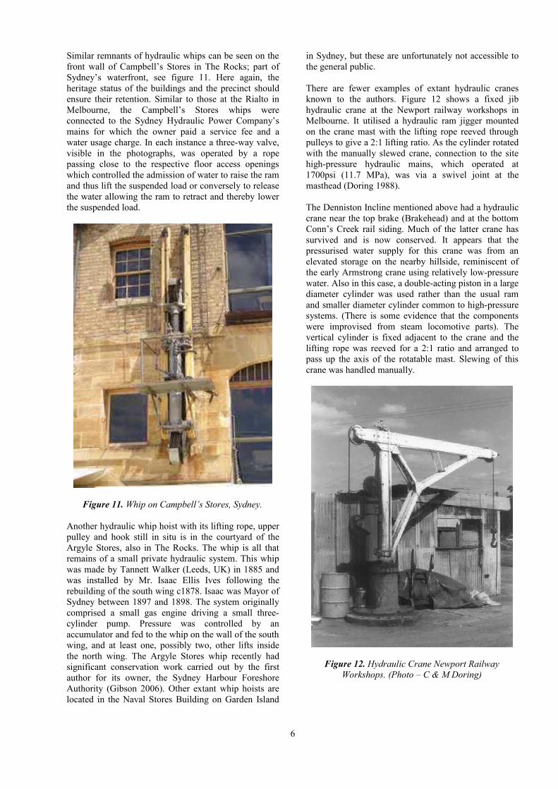
Similar remnants of hydraulic whips can be seen on the front wall of Campbell’s Stores in The Rocks; part of Sydney’s waterfront, see figure 11. Here again, the heritage status of the buildings and the precinct should ensure their retention. Similar to those at the Rialto in Melbourne, the Campbell’s Stores whips were connected to the Sydney Hydraulic Power Company’s mains for which the owner paid a service fee and a water usage charge. In each instance a three-way valve, visible in the photographs, was operated by a rope passing close to the respective floor access openings which controlled the admission of water to raise the ram and thus lift the suspended load or conversely to release the water allowing the ram to retract and thereby lower the suspended load.
Figure 11. Whip on Campbell’s Stores, Sydney.
Another hydraulic whip hoist with its lifting rope, upper pulley and hook still in situ is in the courtyard of the Argyle Stores, also in The Rocks. The whip is all that remains of a small private hydraulic system. This whip was made by Tannett Walker (Leeds, UK) in 1885 and was installed by Mr. Isaac Ellis Ives following the rebuilding of the south wing c1878. Isaac was Mayor of Sydney between 1897 and 1898. The system originally comprised a small gas engine driving a small three- cylinder pump. Pressure was controlled by an accumulator and fed to the whip on the wall of the south wing, and at least one, possibly two, other lifts inside the north wing. The Argyle Stores whip recently had significant conservation work carried out by the first author for its owner, the Sydney Harbour Foreshore Authority (Gibson 2006). Other extant whip hoists are located in the Naval Stores Building on Garden Island
in Sydney, but these are unfortunately not accessible to the general public.
There are fewer examples of extant hydraulic cranes known to the authors. Figure 12 shows a fixed jib hydraulic crane at the Newport railway workshops in Melbourne. It utilised a hydraulic ram jigger mounted on the crane mast with the lifting rope reeved through pulleys to give a 2:1 lifting ratio. As the cylinder rotated with the manually slewed crane, connection to the site high-pressure hydraulic mains, which operated at 1700psi (11.7 MPa), was via a swivel joint at the masthead (Doring 1988).
The Denniston Incline mentioned above had a hydraulic crane near the top brake (Brakehead) and at the bottom Conn’s Creek rail siding. Much of the latter crane has survived and is now conserved. It appears that the pressurised water supply for this crane was from an elevated storage on the nearby hillside, reminiscent of the early Armstrong crane using relatively low-pressure water. Also in this case, a double-acting piston in a large diameter cylinder was used rather than the usual ram and smaller diameter cylinder common to high-pressure systems. (There is some evidence that the components were improvised from steam locomotive parts). The vertical cylinder is fixed adjacent to the crane and the lifting rope was reeved for a 2:1 ratio and arranged to pass up the axis of the rotatable mast. Slewing of this crane was handled manually.
Figure 12. Hydraulic Crane Newport Railway Workshops. (Photo – C & M Doring)
6

5. GOODS AND PASSENGER LIFTS
Whilst some of the earliest lifts or ‘elevators’ were arranged using mechanical drives from engine plant, hydraulic actuators with their inherent linear motion were well suited to the task. The first hydraulic lifts appeared around 1865 and typically utilised low-pressure water from the town mains supply or from an elevated storage tank, although booster pumps driven by a gas engine or similar were sometimes utilised to obtain sufficient operating pressure (Gavois 1983). When public hydraulic power systems were established in some major cities, including Melbourne and Sydney, in the latter part of the nineteenth century the availability of high-pressure water hastened the adoption of hydraulic lifts which in turn facilitated the construction of taller commercial buildings.
The two main types of hydraulic lift were the suspended type using variants of the hydraulic jigger to control the lifting ropes, and the direct acting where the hydraulic ram pushed the lift car from below. For the former arrangement, the hydraulic cylinder could be arranged either vertically in a part of the lift shaft or horizontally in the building basement with suitable rope reeving to the head pulleys from which the car was suspended. The direct acting hydraulic lift on the other hand required a shaft below the lowest landing of the same depth as the height to the uppermost floor to be served by the lift.
Figure 13 shows a c1900 mains pressure hydraulic lift at the former c1824 Government Bond Store on Hobart’s waterfront. The external goods lift, which served three floors in the building, was manufactured by the Austral Otis Company and used the ‘Hales’ standard hydraulic system that originated in the USA. The vertically mounted hydraulic cylinder was of relatively large diameter in view of the low operating pressure and utilised a double-acting piston with dual piston rods that were normally in tension. Operation of the water control valve at the base of the cylinder was by a rope loop that could be pulled by the operator from the lift platform. This historic hydraulic lift was restored by the then Lift Manufacturers Association of Australia from 1982-88 and is still extant, although safety regulations have precluded its continued operation or demonstration.
At No. 1 Kent St, Sydney a hydraulic passenger lift was reconstructed in the atrium of the refurbished building c1992. This lift was originally connected to the Sydney Hydraulic Power Company high-pressure mains. It is ostensibly still an operating lift, in that the hydraulic cylinder is connected to a modern oil based hydraulic system, however like the Hobart lift above, its continued use has been prevented by current lift regulations.
Figure 13. Goods Lift, Hobart Bond Store building (Photo – B Cole)
An in situ passenger lift car and hydraulics remain in the old AGL Gasworks building at the end of Gas Lane, extending to Hickson Rd, in Sydney. The lift shaft has been closed off at each floor to enable productive use to be made of the space, but the passenger car, the hydraulic cylinder, and the counterweight still remain intact. The lift valves were operated electro-mechanically, before this lift went out of service c1975. The car is at the bottom of the shaft at the Hickson Rd, level. A unique feature of this passenger lift is that the cylinder has, cast in along its length, the name of its maker – ‘Sydney Hydraulic Power Co. Ltd’.
The former Melbourne Tramways & Omnibus Company (later MMTB) c1895 head office building at 673 Bourke Street originally contained three hydraulic lifts powered from the MHPC mains. The main lift, enclosed in a mesh-metal ‘shaft’ in the foyer stairwell was later converted to DC motor operation. However, a goods lift that originally served from the basement to the second floor still has its hydraulic cylinder and associated equipment in situ on the sidewall of the lift shaft. It is hoped that this important remnant of the era of high-pressure water hydraulic lifts in Melbourne will be preserved in some meaningful way.
7

The movement of large quantities of coin between street level and the strong rooms (generally below ground level) by the banks was facilitated using hydraulic bullion/coin lifts. These tended to be bigger than passenger lifts but limited in travel height. In one of the Sydney banks the lift floor is 2m x 3.5m with two sets of heavy steel access doors. The steel framework has rolled into it “Dorman, Long & Co. Middlesbro” potentially dating it around the 1930s. The lift is no longer used.
Figure 14 shows the controls of another bullion lift located in a former Sydney bank building, now converted for retail use, This lift has its cylinder and counterweight in situ, as well as the lift car, but recent building work has left it covered in rubble. This lift had been converted at some stage to electrical control. The electro-hydraulic control system including what appears to be a time clock appears to be complete, and much of the pipe-work is still in place. There was no evidence of a pump, but the presence of SHPC control valves behind the building suggests a connection to the SHPC system.
Figure14. Electric Control for Bullion Lift.
6. TEXTILE BALING PRESSES
A large number of hydraulically operated wool presses were installed in many of the wool stores along the shores of the working harbour in Sydney, and in Ultimo/Pyrmont. One extant example is in the Dalgety wool stores building, now apartments, in Jones Street, Pyrmont. To gain sufficient force to press bales, particularly high-density bales for export, the hydraulic pressure supplied from the SHPCo mains was increased about fivefold by an hydraulic intensifier (Figure 15).
These devices essentially comprised a pair of coupled rams with cross-sectional areas in the ratio of the desired pressure step-up ratio, and arranged in ‘low’ and high pressure cylinders respectively. The output of the intensifier was then fed into the wool press hydraulic ram to perform the baling operation (Figure 16). The wool press depicted was manufactured by Austral Engineering Co. in Melbourne, with steelwork from Dorman, Long & Co.
Figure 15. Intensifier for Wool Presses, Sydney.
Other hydraulic wool presses have been recorded in the nearby Farmers and Graziers wool store and such equipment was widely used elsewhere for the baling of textile fibres. Where a public high-pressure hydraulic utility service was not available, the site would require its own in-house high-pressure pumping plant and accumulator. An example of the former is mentioned above for the historic Hobart wool store.
8
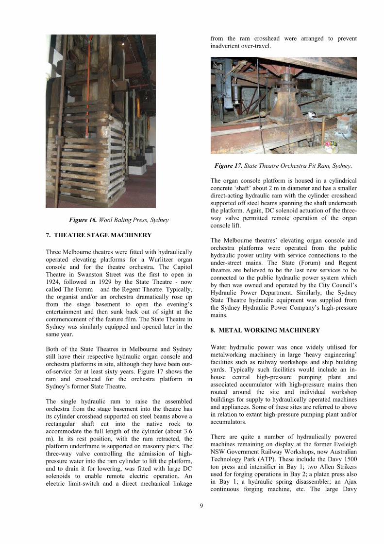
Figure 16. Wool Baling Press, Sydney
7. THEATRE STAGE MACHINERY
Three Melbourne theatres were fitted with hydraulically operated elevating platforms for a Wurlitzer organ console and for the theatre orchestra. The Capitol Theatre in Swanston Street was the first to open in 1924, followed in 1929 by the State Theatre - now called The Forum – and the Regent Theatre. Typically, the organist and/or an orchestra dramatically rose up from the stage basement to open the evening’s entertainment and then sunk back out of sight at the commencement of the feature film. The State Theatre in Sydney was similarly equipped and opened later in the same year.
Both of the State Theatres in Melbourne and Sydney still have their respective hydraulic organ console and orchestra platforms in situ, although they have been out-of-service for at least sixty years. Figure 17 shows the ram and crosshead for the orchestra platform in Sydney’s former State Theatre.
The single hydraulic ram to raise the assembled orchestra from the stage basement into the theatre has its cylinder crosshead supported on steel beams above a rectangular shaft cut into the native rock to accommodate the full length of the cylinder (about 3.6 m). In its rest position, with the ram retracted, the platform underframe is supported on masonry piers. The three-way valve controlling the admission of high-pressure water into the ram cylinder to lift the platform, and to drain it for lowering, was fitted with large DC solenoids to enable remote electric operation. An electric limit-switch and a direct mechanical linkage
from the ram crosshead were arranged to prevent inadvertent over-travel.
Figure 17. State Theatre Orchestra Pit Ram, Sydney.
The organ console platform is housed in a cylindrical concrete ‘shaft’ about 2 m in diameter and has a smaller direct-acting hydraulic ram with the cylinder crosshead supported off steel beams spanning the shaft underneath the platform. Again, DC solenoid actuation of the three-way valve permitted remote operation of the organ console lift.
The Melbourne theatres’ elevating organ console and orchestra platforms were operated from the public hydraulic power utility with service connections to the under-street mains. The State (Forum) and Regent theatres are believed to be the last new services to be connected to the public hydraulic power system which by then was owned and operated by the City Council’s Hydraulic Power Department. Similarly, the Sydney State Theatre hydraulic equipment was supplied from the Sydney Hydraulic Power Company’s high-pressure mains.
8. METAL WORKING MACHINERY
Water hydraulic power was once widely utilised for metalworking machinery in large ‘heavy engineering’ facilities such as railway workshops and ship building yards. Typically such facilities would include an in-house central high-pressure pumping plant and associated accumulator with high-pressure mains then routed around the site and individual workshop buildings for supply to hydraulically operated machines and appliances. Some of these sites are referred to above in relation to extant high-pressure pumping plant and/or accumulators.
There are quite a number of hydraulically powered machines remaining on display at the former Eveleigh NSW Government Railway Workshops, now Australian Technology Park (ATP). These include the Davy 1500 ton press and intensifier in Bay 1; two Allen Strikers used for forging operations in Bay 2; a platen press also in Bay 1; a hydraulic spring disassembler; an Ajax continuous forging machine, etc. The large Davy
9

forging press used hydraulic power in conjunction with steam cylinders (Butcher 2004).
The Midlands Railways workshops in Perth, Western Australia, likewise utilised hydraulically powered machines including a 1000 t Fielding press (Figure 17), other forge presses, spring presses and hydraulic riveters.
Figure 18. Fielding Press, Perth. (Photo – C & M Doring)
Similarly, when surveyed in 1888, the Victorian Railways very extensive Newport Workshops had a range of hydraulically powered machine remnants, including the 2t hydraulic jib crane mentioned earlier along with various presses, riveters, etc. (Doring 1988). Although some items had been partially disassembled, the Heritage Listing of the workshops site will hopefully preserve these machine tools from an earlier age.
The Cockatoo Island dockyard in Sydney Harbour also distributed high-pressure water from pumps located in the central powerhouse for use by hydraulic riveters, presses, plate bending machines and other heavy machines associated with shipbuilding. A large platen press and a heavy plate-bending machine are readily visible to visitors to the site but are no longer protected by an enclosing building.
9. HYDRAULIC POWER PIPING SYSTEMS
Both the Melbourne and Sydney public hydraulic power systems had an extensive network of high-pressure pipes buried under CBD roads and footpaths, a majority of which remain, albeit out-of-sight. The Sydney system had about 80 km of piping at its peak. The mains were typically 6 inch (150 mm) and 4 inch (100 mm) thick-walled cast iron pipes with two-bolt oval flange joints incorporating a resilient gutta-percha seal ring. Smaller pipes including those for individual customer services were commonly of thick steel tubing. High-pressure valves for isolating mains sections and for customer take-offs were identified by cast-metal valve pit covers set flush into footpath and roadway pavements (Figures 19 and 20). Fortunately, from a heritage perspective, many of these remain in both Melbourne and Sydney
streets. The former bear the identification ‘Hydraulic Power Co.’ or (post 1925) ‘Hydraulic Power Dept.’, and the latter ‘SHPC’ or ‘HPCo.’ About 150 remain in Sydney’s streets and at least half that number in Melbourne
Figure 19. Valve Cover, Melbourne.
Figure 20. Valve Cover, Sydney.
Some exposed 4” (100mm) main exists in Hickson Rd, Sydney (near High St.). Oval flange joints for each section of this pipe have ‘SHPCo.’. cast into the side of the flange.
High-pressure hydraulic piping, valves and other fittings are also in evidence to a greater or lesser extent at most of the other places that have already been mentioned in relation to extant hydraulic power system remnants.
Figure 21. HP Joint on Remnant 4” Main, Sydney.
10

10. OTHER INSTALLATIONS
Bank Doors
Several of the prominent Banks in Sydney’s central business district had their external doors operated by hydraulic power from the Sydney Hydraulic Power Company system mains. Typically, these doors were up to 6 m high and 3.5 – 5.5 m wide (Figure 22). They were constructed of steel frames clad with rolled bronze sheeting. The operating system on some was through a direct acting piston, with the cylinder in the basement extending down into a pit below the door to enable full travel. A typical cast iron piston of the period was 100 mm diameter, with the cast iron cylinder 180 mm diameter providing a lifting capacity of up to 4 ton.
Figure 22. Hydraulically operated Bank Doors, Sydney.
The alternative arrangement was for a combination of hydraulics, pulleys and counterweights to be used. One of the doors on the Commonwealth Bank in Pitt St still operates on this format, although it has been converted to oil operation. The saving here is in the reduced length of travel of the piston, the fact that the shorter cylinder is mounted on the wall behind the door in the basement, and the reduced piston diameter for similar load capacities. The control valves (3-way) in each case are located on the foyer level of the building.
Disappearing Guns
William Armstrong, who pioneered the development of water hydraulic power systems and related equipment from the middle of the nineteenth century, was later also involved in the development and manufacture of armaments and for which he subsequently received a knighthood. In the early1880s Armstrong combined the two technologies in his disappearing gun carriage which utilised a hydro-pneumatic system to absorb the recoil of his 6-inch and 8-inch guns. In this way the energy could be reused to later return the heavy gun to its elevated firing position after it was reloaded out-of-sight within the gun emplacement. The arrangement afforded greater safety for the gun crew and the gun itself was
only briefly visible to the enemy above the emplacement parapet when it was elevated for firing.
Disappearing guns were installed in many British Empire coastal defence fortifications from around 1885 as a precaution against a then perceived possible Russian offensive. In Australia these included fortifications for Port Phillip Bay, Sydney Harbour, Brisbane River and in New Zealand, for Auckland, Wellington, Lyttelton and Dunedin harbours.
Figure 23. Disappearing Gun, Taiaroa Head, Dunedin.
The recoil hydro-pneumatic cylinder that connected to the gun trunnion was both massive and complex, with multiple internal chambers and flow control valves. It operated at pressures up to 1600 psi (11 MPa) (Harding 1896). A multi-cylinder manually operated pump was used to initially charge the cylinder and/or to top-up the pressure between firings. In practice, the added complexity of the disappearing gun carriage was soon found not to justify its originally presumed benefits and they fell out of favour for subsequent defences.
Remnants of the disappearing carriages, with and without their guns, exist at many of the above mentioned former coastal defence installations, but Dunedin harbour has the distinction of having a fully restored 6-inch disappearing gun in situ at Taiaroa Head fortifications on the Otago Peninsula (Figure 23).
Water Hydraulic Braking
New Zealand’s famous c1880 Denniston Incline for lowering loaded rail wagons from coal mines on the Mt Rochfort plateau to the west coast for shipment out of Westport on the South Island made use of high-pressure hydraulic pump engines for purposes of braking. The incline was constructed as two contiguous sections with each one using twin winding drums on a common shaft arranged to lower a loaded rail wagon down the incline and at the same time pull up an empty wagon. The speed of operation was controlled by double-acting hydraulic engines driven by cranks from the winding drum shaft, with the water flow rate from one side to the other of the cylinders regulated manually by the operator. Provision was made to bleed-off the resultant
11

hot water and to replace it from a nearby tank. The Denniston Incline with its two rope haulage sections operated up until 1967 (Figure 24).
Figure 24. Remnants of Middle Hydraulic Brake, Denniston Incline. NZ. (Photo – J Staton)
11. CONCLUDING REMARKS
The development of high-pressure water hydraulic power systems and equipment from the middle of the nineteenth century extended the reach of the steam engine by being able to efficiently transmit energy for motive power purposes at distance ranging up to ten or more kilometres and opened the way for a wide range of hydraulically powered devices. These included cranes and hoists, goods and passenger lifts, textile baling presses, theatre and stage machinery and heavy workshop machines and tools. A central pumping station could be used to serve a large industrial facility or a city area, with the motive power conveniently conveyed in pipes. No longer was it necessary to have engines close to each end-use device or line shafting and open belts to serve a group of powered equipment.
The development of electricity generation at central stations and distribution by wires and cables for motive power applications challenged water hydraulic power systems from the latter years of the nineteenth century and ultimately superseded it. However, many water hydraulic systems and end-use devices remained in-service well into the twentieth century with some only ceasing in the last quarter. Nevertheless, once retired from service much of the former long serving equipment ended up as scrap metal. It is therefore important to identify, record and if practicable conserve significant remaining examples of this phase of motive power transmission and end-use applications. This paper has briefly described some extant remnants but the authors would be pleased to receive information on other sites where hydraulic plant and equipment still exists.
12. REFERENCES
1. Armstrong, W G 1858, On Water Pressure Machinery, Proceedings of the Institution of Mechanical Engineers, London.
2. Armstrong, W G 1877, The History of the Modern Development of Water-pressure Machinery, Proceedings of the Institution of Civil Engineers, vol. 50, May 1887.
3. Bairstow, D 1986, Hydraulic Power and Coal Loading at Newcastle Harbour, New South Wales, Australian Historical Archaeology 4, p57-66.
4. Butcher, R K 2004, The Great Eveleigh Railway Workshops, Richard Butcher, Sydney
5. Cockbain, P 1998, The Engineering Heritage Associated with Coal Shipment from Newcastle 1877 to 1967, 9th National Conference on Engineering Heritage, Ballarat.
6. Doring, C & M J 1988, Heritage Study of the Newport Workshops, for Victorian Railways (V Line).
7. Gavois, J 1983, Going Up, Otis Elevator Company
8. Gibson, J W 2006, Conservation Management Plan for Hydraulic Whip, Argyle Stores, Argyle St, The Rocks, Prepared for Sydney Harbour Foreshore Authority: Sydney.
9. Harding, R 1896, Hydro-pneumatic Disappearing Guns and Carriages as used in Victoria, Victorian Institute of Engineers, 2 September.
10. McNeil, I 1968, Joseph Bramah – A Century of Invention 1749 – 1851, David & Charles, Chapters 7 and 11.
11. Petchey, P G 2007, Denniston - Archaeological Survey Report for the Department of Conservation West Coast Conservancy, N Z, Southern Archaeology Ltd.
12. Pierce, M 2008, The Melbourne Hydraulic Power Company and public hydraulic power systems in Australia, Australian Journal of Mechanical Engineering, Online.
13. Pugh, B 1980, The Hydraulic Age, Mechanical Engineering Publications Ltd., London.
Note: Unless otherwise indicated photographs are by the authors.
12

Appendix A
The Hydraulic Power System.
13