refractive-turbulence contribution to incoherent backscatter heterodyne lidar returns
TRANSCRIPT

Vol. 71, No. 6/June 1981/J. Opt. Soc. Am. 687
Refractive-turbulence contribution to incoherent backscatterheterodyne lidar returns
Barry J. Rye
Department of Applied Physics, University of Hull, Hull, HU6 7RX, England
Received June 4,1980; revised manuscript received November 3,1980
Siegman's theorem is used to express the heterodyne signal from incoherent backscatter lidar in terms of fields inthe target plane. It is then shown directly that, contrary to some previously documented predictions, the mean re-turn from a matched transceiver lidar is, as a consequence of its self-adaptive properties, invariably degraded lessby turbulence than is that of a bistatic system; established results for the irradiance statistics of beams propagatingin the turbulent atmosphere enable beam centroid and scintillation wander tracking to be distinguished as contrib-uting to this result. A combination of the two systems can give rise to near-field transceiver returns that are greaterthan returns for free-space propagation of untruncated Gaussian beams. Target-plane expressions for signal vari-ance display the dependence of signal statistics on antenna geometry, and application of these results to return-power estimation is briefly discussed.
1. INTRODUCTION
Although refractive turbulence is expected to influence theperformance of coherent lidar systems that use incoherentbackscatter from diffuse targets (including atmosphericaerosols), there appears at the time of this writing to have beenno discussion of this in the journal literature. In early re-ports," 2 calculations based on the extended Huygens-Fresnelprinciple and employing the square-law approximation to thelong-term structure function3 indicated a reduction in theheterodyne signal for Gaussian profile beams. Whereas it wasrecognized that these calculations referred to a lidar thatemployed well-separated receiver and transmitting optics,described as a bistatic system in this paper, it was suggested1
that the performance of lidars that use a common antenna ortransceiver would be further degraded. Yura4 has pointedout that in the latter application the outgoing and return ra-diation may traverse the same atmospheric channel in a timethat is short compared with the coherence time of path fluc-tuations so that turbulence-induced phase fluctuations shouldbe averaged over the round trip rather than over each pathseparately. By simply doubling the one-way fluctuationsbefore averaging, Yura predicts a transceiver loss relative toa bistatic system of up to -3 dB in strong turbulence, i.e.,where the spherical-wave coherence length po is much lessthan the antenna-plane beam diameter D.
This procedure is called into question by reference to Fig.1. In Fig. 1(a) the effects of turbulence on the transmittedbeam profile in the far field (i.e., at the focus of a transmittedconverging beam or at long range r >> D 2/X for a collimatedbeam) are indicated schematically; at a given instant these arewell known3 to include beam spread and distortion that aredue to the focusing and defocusing produced by smaller-scaleatmospheric inhomogeneties, whereas in the longer term theinstantaneous center of the beam wanders over a radius suchthat the overall beam spread is characteristic of an apertureof approximate diameter po, where this is less than D. In Fig.1(b) a similar profile is indicated for the (imaginary) back-
propagated local-oscillator (BPLO) beam that can be con-structed according to Siegman's prescription5 6 in order todefine the antenna or directional properties of a heterodynereceiver; the diagram demonstrates that, since the BPLOpropagates independently in a bistatic system, the instanta-neous overlap of the two beams will be incomplete. For whatwill be termed a matched transceiver system, in which theBPLO field at the antenna aperture is identical with that ofthe transmitter, then, as depicted in Fig. 1(c), the two beamspropagate along the same path and are subject to the samedistortion. In this case the receiver sees all the illuminatedarea on the target plane all the time; the matched transceiveris self-adaptive to both beam wander and distortion, so itsperformance may be expected to be superior to that of a bi-static system.
A more quantitative estimate of the transceiver advantage,together with further physical insight, can be obtained byderiving expressions for the moments of the signal current interms of the target-plane irradiance profiles depicted in Fig.1. Such expressions have been used previously by a numberof authorsl" 7' 8 for free-space propagation when the irradiancesare deterministic. They are especially appropriate for pulsedlidar systems in which, even for atmospheric backscatter, thedepth of the target can be neglected. Degnan8 has recentlysuggested (mutually independently of the present writer) thatuse of the BPLO concept might clarify the lidar problem inturbulence. The advantage of this perspective is that it re-duces the problem to one of beam propagation, which is anextensively documented area in the refractive-turbulenceliterature.
TARGET-PLANE EQUATIONS
2.1 Phase-Conjugate or Back-Propagated Local-Oscillator ConstructionIt is useful in view of what follows to review first the principlesunderlying Siegman's theorem. The amplitude of the com-
0030-3941/81/060687-05$00.50 ©D 1981 Optical Society of America
Barry J. Rye

688 J. Opt. Soc. Am./Vol. 71, No. 6/June 1981
(C)
Fig. 1. Schematic diagrams of (a) beam propagation in turbulence;(b) transmitter and BPLO beams for bistatic lidar; (c) same formatched transceiver system.
plex photodetector heterodyne current can be written as
i = 2(-qe/hv) TAD Vs(a)VL*(a)d 2a, (1)
where (,qe/hv) is the current responsivity and the integral overa is carried out within the photodetector surface area AD.The V(a) represent optical fields in this plane; subscripts Sand L describe the scattered (signal) and local oscillator, re-spectively; physically VL* (a) represents a field identical with
r
u(b) = f V(a)h(b,a)d 2a, (2)
where h(b,a) is the impulse response for propagation from thephotodetector plane (position vector a) to the receiving an-tenna plane (b), and if, for fields propagating in the oppositesense, we have
V*(a) = fu*(b)h(a,b)d 2b, (3)
then h(b,a) = h(a,b). It is then easily shown from Eq. (1)that
i = 2(je/hhv) TA us(b)UL*(b)d 2b, (4)
where AR is the area of the receiving antenna that aperturesus(b). A similar derivation can be used for higher momentsof interest in the context of incoherent backscatter, so that,for example, the mean-square current amplitude can bewritten
(i 2 ) = 2(-qe/hv)2 TA TA (VS(al)Vs*(a2)VL*(al)ADAD
X VL(a 2 ))d 2 ald 2 a2
= 2(ie/hv) 2 TA TA (us(bl)us*(b 2 )UL*(hl)UL(b2))
ARAR
X d 2bid 2 b2 . (5)
Shapiro9 has shown formally that the reciprocity theoremcan be extended to problems of propagation in refractiveturbulence. This result can be used to find (i 2 ) in terms ofthe fields U(s) in the target plane. Writing the backscatteredfield as Us(si) - I UT(sl)Iexp(jUl), where UT is the field ofthe transmitted beam, 01 is the random phase of the scatteredreturn at sl, and the backscattering coefficient is assumed tobe uniform and time independent, we have, by developing Eq.(5),
(i 2) S f(US(Si)UL*(Sl)US*(S2)UL(S2))d 2S1 d2 S2
-( I UT(Sl1f IUT(S2)IUL*(S1)UL(S2))X (eJ(tV-k2))d 2 s 2 d2 s2
= IT(s)IL(S)d 2s, (6)
where the target-plane irradiance profiles I(s) = I U(s) 12, and,since the 0 are uniformly distributed, we can put
(eJ(k1-2)) - 6(Sl - S2).
The details of the relation between IT and Is (i.e., the back-scattering coefficient) are omitted since this is unimportantbelow. The integral is to be evaluated over the target area,but it will be supposed here that this is sufficiently extendedso that the limits are infinite.
-- N LONG TERM AVERAGE SPREAD
IRADIUS - Xr a(FAR FIELD)
Ik WANDER
ANTENNA- N\
BEAM BREAK-UP ANDTARGET SHORT-TERM SPREAD
(a)
' A
ANTENNA
TARGET
VL (a) except that the direction of propagation is reversed.Siegman's prescription for determining the antenna propertiesof a coherent receiver states that the geometry of the phase-conjugate local-oscillator or BPLO beam generated fromVL*(a) can be exploited to write the integral in Eq. (1) interms of fields in any plane within the optical system. Thisprinciple is usually used overtly or otherwise to transform theexpression into the antenna plane. The method depends onthe reciprocity theorem, i.e., if a field in the antenna plane isexpressed by the superposition integral
Barry J. Rye
ER
Vol. 71, No. 6/June 1981/J. Opt. Soc. Am. 689
2.2 Evaluation of (j2)
In practice the integrand can be evaluated from the an-tenna-plane fields by writing h(s,b) explicitly, giving
(IT(S)IL(s)) = SUT(b'1)UT*(b'2)UL*(b,)UL(b 2)X (h(s,b',)h* (s,b' 2)h*(s,bt,)h(s,b 2 ) )d2 b',d 2b'2d2b d2b2,
(7)
where3
(h(s,b'i)h*(s,b' 2)h*(s,bl)h(s,b 2 ))= exp Uk (#' - j) * s/r]expik [(b'l)2- (b'2 )2 - bl 2 + b 2
2 ]/2r}H(s;b',,b' 2 ,bi,b 2). (8)
The prime coordinate vectors refer to positions within thetransmitter aperture ' = b'l - b'2 , = b - b2, and
H(s;b',,b' 2,bib 2)
= expj-1/2[D(Q3') + D(Q) + D(lb'l - bi + O1')
+ D(lb' 2 -b 2 l)-D(Ib',-b 2l)-D(lb' 2 - blf)]j (9)
is a special case of the second-order spherical-wave coherencefactor' 0 in the Gaussian log-amplitude and appropriatephase-only approximations." In calculating (i 2) by substi-tution of Eqs. (7)-(9) into Eq. (6), it is useful to follow Cliffordet al." in first evaluating the integral over s; the transform
f expLjk(o' - 1) s/rjd2 s = (1' - /)can then be used to give
S(IT(s)IL(s))d2s= fUT(b'i)UT*(b'2)UL*(bl)UL(b2) expUk(b'1) 2
- (b' 2)2
- bi2 + b22 ]/2rIH'(s;b',,b'2 ,bj,b2 )d2 b'ld2 b'2 d2 bid2 b2 ,
where the modified coherence factor for 1B' = is obtainedfrom Eq. (9) as
H'(s;b',,b'2,b,,b2) = H(s;b',,b'l - 3,b,,b, - /)= expj-[(D/fl) + D(Ib'l - bil)
-l/2 D(Ib',-bl + /1J) - l/2 D(ib', -b,- 13)]. (10)
If the square-law approximation D(/) (0/po)2 to thestructure function is employed, there results H' = 1, i.e., tur-bulence has no influence on the integral. Since use of thesquare-law structure function corresponds to the assumptionthat the only effect of turbulence is beam wander or tilt 12,13
it is deduced" that the integral can be calculated correctly byusing the long-term 5/3-law structure function D(,B) = (,/p0)
5 13, even though, as we have seen in the transceiver case, the
system has short-term self-adaptive properties. We see fromEqs. (7)-(9) that use of the square-law structure function doesnot make H = 1, so that computations of the integrand usingthese equations'4 include the effects of tilt. The result istherefore obtained that, although (IT(S)IL(S))LT 5 (IT(S)IL (S) ) WT, Eq. (6) can be rewritten as
(iW) -(IT(s)IL(s)WLTd 2 S = S(IT(S)IL(s))wTd 2 s, (11)
where LT represents the long-term and WT the wander-tracked (or short-term) averages. On physical grounds, thesurface integral of any moment of a field formed by linearsuperposition of (Huygens's) point-source fields might beexpected to be independent of directional effects, such astilt.
2.3 Higher-Order MomentsIt was noted above that the reciprocity relation can be usedto compute all moments of i in terms of the target-plane fields.To find (i4 ), which is needed in order to determine the vari-ance of (i2 ) and characterize fading, one obtains, by analogywith Eqs. (5) and (6),
(i4) - ( us(bl)us*(b 2 )us(b3 )Us*(b4 )uL*(bl)uL(b2)uL*X (b3)uL (b4 ) )d2bid 2 b2d2b3d2 b4
- S (Us (S,)US* (S2)us (S3)US* (S4)UL* (S1)UL (S2)UL*X (S)UL (S4 ))d 2 s d2s~d2 s3 d2 s4
= S(iuT(sDIjUT(S2)HUT(S3) IUT(S4)IUL*(Sl)ULX (S2)UL* (S3)UL (S4) )X (exp[-j(0j - 02 + 03 -. 4 )])d2 sid2s2d2sAd2s4
= 2S (IT (S1)IT (S2)IL (Sl)IL (S2) )d2sld 2s 2, (12)
where, as the phases 0 are uniformly distributed,
(expfU(01 - 02 + 103 - 04)]) '(01 - 02)t(03 - 04)
+ 6(01 - '04)6(12 - 03)-
For free-space propagation in which the irradiances aredeterministic, this becomes
(i4) - 2SIT(sI)IT(S2)IL (sl)IL (s2)d2sld2 S2= 2[fIT(s)IL(s)d 2s]2 = 2(i2 )2
(13)
[cf. Eq. (6)], so that the normalized variance of j2 is
0'p2 = (j4) - (i2 ) 2)/(i 2 )2 = 1,
as expected for exponentially distributed free-space speckleirradiance. To characterize the effects of the turbulencecontribution, it is convenient to use the function
Uex2 = 2 - 1
= 2 S (IT(SIT(S2)IL (s,)IL (s2) )d2s&d2s2 1, (14)
which can be interpreted as the excess noise in the return thatis due to atmospherically induced irradiance correlation in thetarget plane.
3. MATCHED SYSTEM MEAN RETURNS
The bistatic lidar result in the presence of turbulence can beobtained by assuming independent beam paths, so that Eq.(6) becomes
(i2 )B f(IT(S)IL(s))d2 s = f(IT(S))(IL(s))d2 s. (15)
Where the antenna-plane beam profiles are matched, (IT (S))( IL(S)) and, in this case,
(i 2 )MB - f(IT(s)) 2d2 S. (16)
For the matched transceiver considered above, thegeometries of the BPLO and transmitted beam are at all in-stants identical, so that IT(S) IL (S), and Eq. (6) yields
(i 2 ) MT - .f(IT 2 (s))d 2 s = f[1 + rI2(s)] (IT(s)) 2 d2 s. (17)
Since the normalized irradiance variance or scintillationindex 3 UI2 (S) is positive definite, comparison of Eqs. (16) and(17) demonstrates formally the transceiver advantage. Thisconclusion depends only on the validity of the reciprocityrelation and not on assumptions about propagating beam
Barry J. Rye
690 J. Opt. Soc. Am./Vol. 71, No. 6/June 1981
Gld B)
3
01 10 No 100
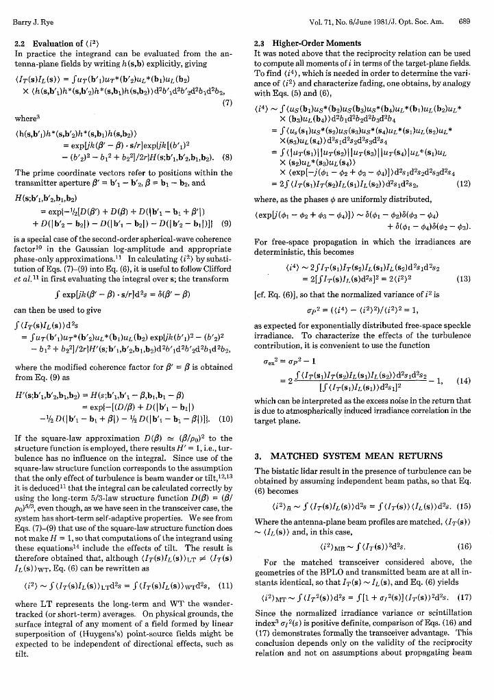
Fig. 2. Gain G GBCGsc against NO = DipO from approximate model(dashed lines) compared with curves from Clifford and Wandzura' 5
(solid lines). Also plotted is GBC for Q = 4.
statistics. Physically the enhancement occurs because, fora matched transceiver in turbulence, the BPLO weights pre-cisely those areas on the target receiving increased illumina-tion from the transmitter, producing a similar result to re-duction in the extent of the beam at the target. As discussedabove, it is immaterial whether .the averages in these equationsare computed with wander-tracked or long-term formulas.
Computation of what are effectively these formulas by usingthe long-term structure functions [cf. Eq. (11)] has been car-ried out by Clifford and Wandzura' 5 for an untruncatedGaussian beam geometry. In order to preserve physical in-sight into the reasons for the transceiver advantage, it is in-structive to evaluate Eq. (17) approximately by using availableexpressions for the wander-tracked beam spread, scintillationindex, and on-axis irradiance. We define the gain of thematched transceiver relative to a matched bistatic system byusing Eqs. (11), (16), and (17) as
- S(1 + u,)WTUcT)WT2d2Sf ( IT ) LT 2d2S
(18)
The following approximations can now be made. First weassume that
[ca2(S)]WT [o12(0)]WT = (Cr2)WT-
Recent computations' 7 suggest that [aI2(s)]LT increases withs for beam propagation, but some part of this dependence isdue to the enhanced effect of wander near the edges of thebeam and will not apply to wander-tracked measurements;assigning [j2(S)]WT the on-axis value will in any event yielda conservative estimate of G. [Uj2(0)]WT is found' 6 to increaseto a maximum value of unity for Dlpo > 1; it appears that,unlike [lU,2(0)]LT, it does not exceed unity. In order to modelthe scintillation gain, the expression
[VI2(0)]WT = -exp[-oy] (19)
is used, in which the scintillation index in the weak uni-form turbulence approximation is given by3
U12 = 2.257(r/kpo2)5/6.
As a second approximation, we assume a Gaussian beamthat preserves its profile. It is then easily shown that
(IT(s)) 2d's = (T 2 1a = -PT (IT (0)),j T 7r(P., ) 2
where PT = S(IT(s)) d2s and (p02) is the mean-square (1/e 2 )
beam-irradiance radius in the target plane. Hence expres-sions for short-term beam radius 3 or wander-tracked on-axisirradiance (IT(0))WT1 6 can be used for estimating the gain.Taking the former, Fante's Eq. (39), which is valid for NoDlpo >> 1, r Z kD2/NO 2 , can be used to give the beam centroidwander-tracking gain
(IT(O))WT (PS2 )LTGBCn ==
(IT(O)LT (P 2 )WT1 + Q2 + N2
1 + Q2 + N 02(l - 0.62N0-1/3)6 /5
(20)
where Q = (kD /4) 1 ro - 1/r i, ro being the range at which thetransceiver is focused.
With these approximations, Eq. (18) gives G as a productof GBC and GSC. In Fig. 2, G, calculated in this way for acollimated output, is compared with values taken manuallyfrom the curves presented by Clifford and Wandzura15 ; inboth cases G is referred to bistatic calculations that use thesquare-law structure function. Agreement in the near field(Q = 4,16) is within 1 dB throughout and usually (apart fromthe region N - 10 on the Q = 4 curve) within 0.5 dB. Thefailure of the approximation in the far field in weak turbulenceM = 0, N 0 < 3) is not surprising in view of the conditions forvalidity of Fante's formula from which Eq. (20) is derived; useof Dunphy and Kerr's expressions'6 for the on-axis irradianceof a wander-tracked focused beam leads to curves similar tothose of Fig. 2 with improvement in the agreement at large N 0 .
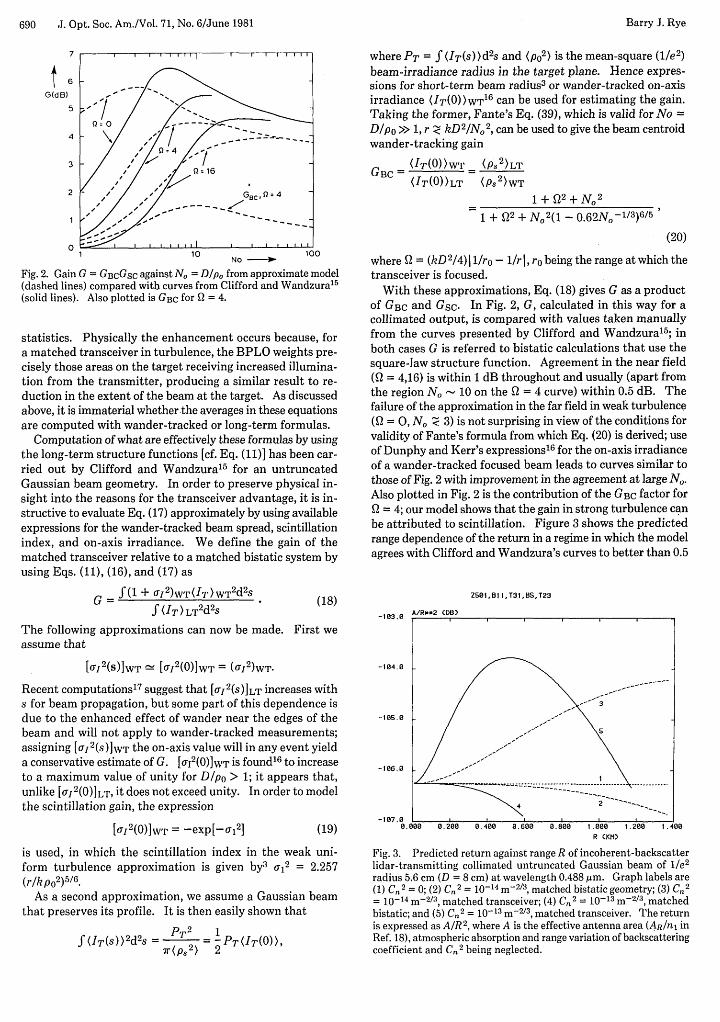
Also plotted in Fig. 2 is the contribution of the GBC factor forQ = 4; our model shows that the gain in strong turbulence canbe attributed to scintillation. Figure 3 shows the predictedrange dependence of the return in a regime in which the modelagrees with Clifford and Wandzura's curves to better than 0.5
Z501,B1 1j,T31,8S,T23
-183.2 A/R.*2 (DB)
-104.0
-185.0
-107.0 La.800 0.200 0.400 0.600 8.880 1.088 1.2-0 1.400
R CKM)
Fig. 3. Predicted return against range R of incoherent-backscatterlidar-transmitting collimated untruncated Gaussian beam of l/e2radius 5.6 cm (D = 8 cm) at wavelength 0.488 ,um. Graph labels are(1) C. 2 = 0; (2) C.' = 10-14m-2/ 3 , matched bistatic geometry; (3) C,2= 10-14 m-2/3, matched transceiver; (4) C,2 = 10-13 m-2/3, matchedbistatic; and (5) C 02 = 10-13 m"2/3 , matched transceiver. The returnis expressed as A/R2, where A is the effective antenna area (AR/ni inRef. 18), atmospheric absorption and range variation of backscatteringcoefficient and Cn 2 being neglected.
- -2-- -- -
Barry J. Rye

Vol. 71, No. 6/June 1981/J. Opt. Soc. Am. 691
dB throughout; an interesting consequence of the reductionin effective extent of the target is enhancement of the meanmatched transceiver return compared with its free-space valueat intermediate ranges.
4. VARIANCE OF MATCHED SYSTEMRETURNSFor the matched bistatic lidar, Eq. (12) simplifies to
(i4)MB - 2S(IT(s1)IT(s2))2 d2 sjd2 s2,
whereas, for the matched transceiver,
(W4 )MT - 2 f (IT 2(S 1IT2 (S2))d 2sld2s2.
(21)
(22)
By an argument analogous to that used when discussing Eqs.(16) and (17), it follows that (j4iMT > (i
4)MB. However, it
is not immediately clear for which geometry the normalizedvariance will be the greater. Computations of Eq. (12) requirethe fourth-order spherical-wave coherence factor.
It should be noted that the various processes leading tobeam spread and wander have disparate time constants, sothat signal variances calculated by using Eq. (12) refer directlyto independent samples separated in time by more than thelongest fluctuation period in the system. By taking samplesmore frequently, it may be possible to average out the specklecontribution in a,
2 and hence reduce the overall variancewithin this period; it will not be possible in this way to reducethe excess-noise term uex 2, which arises from the longer-termfluctuations. Hence the practical effect of finite Uex2 on theestimation of mean return in pulsed incoherent backscatterlidar is to delimit the single-pulse sample rate and thereforethe useful bandwidth of such systems. Equation (14) showshow evaluation of Uex
2 is an antenna problem; since the slowestirradiance fluctuations arise from beam wander,3 it should bepossible to average the excess noise more rapidly by using atransceiver rather than a bistatic geometry.
This work was carried out under a contract with the Com-mission of the European Communities Environmental Re-search Programme in collaboration with E. L. Thomas.Comparison with the computations of Ref. (15) in the revisedversion of this paper was made possible during an extendedvisit to the Wave Propagation Laboratory at NOAA, Boulder,Colorado, on the invitation of R. M. Huffaker; it was sup-ported by a NATO research grant. I am indebted to S. F.Clifford for permission to quote these data and to B. A.Greene, in addition to those mentioned above, for stimulatingdiscussions.
REFERENCES
1. A. Thomson and M. F. Dorian, "Heterodyne detection of mono-chromatic light scattered from a cloud of moving particles," Rep.GDC-ERR-AN-1090 (General Dynamics Convair Division, SanDiego, Calif., 1967).
2. S. S. R. Murty, "Laser Doppler systems in atmospheric turbu-lence," NASA Tech. Memo TMX-73354 (U.S. GovernmentPrinting Office, Washington, D.C., 1976).
3. R. L. Fante, "Electromagnetic beam propagation in turbulentmedia," Proc. IEEE 63, 1669-1691 (1975).
4. H. T. Yura, "Signal-to-noise ratio of heterodyne lidar systems inthe presence of atmospheric turbulence," in Surveillance ofEnvironmental Pollution and Resources by ElectromagneticWaves, T. Lund, ed. (Reidel, London, 1978), pp. 67-93.
5. A. E. Siegman, "The antenna properties of optical heterodynereceivers," Appl. Opt. 5, 1588-1594 (1966); Proc. IEEE 54,1350-1356 (1966).
6. D. L. Fried and H. T. Yura, "Telescope-performance reciprocityfor propagation in a turbulent medium," J. Opt. Soc. Am. 62,600-602 (1972).
7. T. S. Chu, "On coherent detection of scattered light," IEEETrans. Antennas Propag. AP-15, 703-704 (1967).
8. J. J. Degnan, "Design considerations for optical heterodyne re-ceivers. a review," presented at NASA Heterodyne SystemsTechnology Conference, Williamsburg, Virginia, March 1980.
9. J. H. Shapiro, "Reciprocity of the turbulent atmosphere," J. Opt.Soc. Am. 61, 492-495 (1971).
10. M. H. Lee, J. F. Holmes, and J. R. Kerr, "Generalized sphericalwave mutual coherence function," J. Opt. Soc. Am. 67, 1279-1281(1977).
11. S. F. Clifford et al., "Study of a pulsed lidar for cross-wind sens-ing," NOAA Tech. Memo ERL WPL-48. (U.S. GovernmentPrinting Office, Washington, D.C., 1980).
12. D. L. Fried, "Statistics of a geometric representation of wavefrontdistortion," J. Opt. Soc. Am. 55, 1427-1435 (1965).
13. S. M. Wandzura, "Meaning of quadratic structure functions,"J. Opt. Soc. Am. 70, 745-747 (1980).
14. Computations of (I2(0)) using the extended Huygens-Fresnelequations in the phase-only approximation, i.e. (in the presentcontext), of the integrand (IT(O)IL(O)) using Eqs. (7)-(9) for thematched transceiver geometry, where IT = IL, have been madein the course of calculating the long-term scintillation index[o92(0)]LT by V. A. Banekh et al., "Focused laser beam scintilla-tions in the turbulent atmosphere," J. Opt. Soc. Am. 64, 516-518(1974) and by M. H. Lee et al., "Variance of irradiance for satu-rated scintillations," J. Opt. Soc. Am. 66, 1389-1392 (1976).
15. S. F. Clifford and S. M. Wandzura, "The effect of the turbulentatmosphere on monostatic heterodyne lidar performance," Appl.Opt. (submitted for publication).
16. J. R. Dunphy and J. R. Kerr, "Turbulence effects on target illu-mination by laser sources: phenomenological analysis and ex-perimental results," Appl. Opt. 16, 1345-1358 (1977).
17. M. Tur and M. J. Beran, "Propagation of a finite beam througha random medium," Opt. Lett. 5, 306-308 (1980).
18. B. J. Rye, "Antenna parameters for incoherent backscatter het-erodyne lidar," Appl. Opt. 18, 1390-1398 (1979).
Barry J. Rye