the heterodyne receiver
TRANSCRIPT
8/3/2019 The Heterodyne Receiver
http://slidepdf.com/reader/full/the-heterodyne-receiver 1/7
3/31/2005 The Heterodyne Receiver.doc 1/7
Jim Stiles The Univ. of Kansas Dept. of EECS
The Heterodyne Receiver
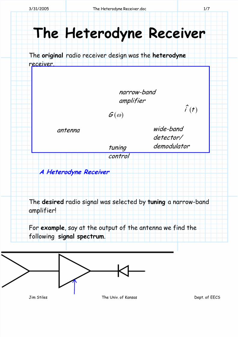
The original radio receiver design was the heterodyne
receiver.
The desired radio signal was selected by tuning a narrow-band
amplifier!
For example, say at the output of the antenna we find the
following signal spectrum.
A Heterodyne Receiver
( )G ω
( )ˆ i t
wide-band detector/
demodulator tuning control
narrow-band amplifier
antenna
8/3/2019 The Heterodyne Receiver
http://slidepdf.com/reader/full/the-heterodyne-receiver 2/7
3/31/2005 The Heterodyne Receiver.doc 2/7
Jim Stiles The Univ. of Kansas Dept. of EECS
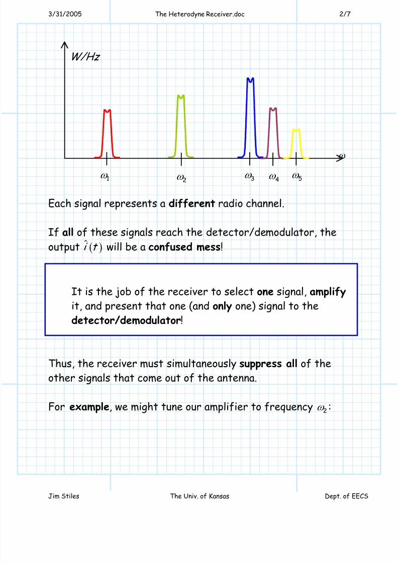
Each signal represents a different radio channel.
If all of these signals reach the detector/demodulator, the
output ( )i t will be a confused mess!
It is the job of the receiver to select one signal, amplifyit, and present that one (and only one) signal to the
detector/demodulator!
Thus, the receiver must simultaneously suppress all of the
other signals that come out of the antenna.
For example, we might tune our amplifier to frequency 2ω :
ω
1ω 2ω 3ω
4ω 5ω
W/Hz
8/3/2019 The Heterodyne Receiver
http://slidepdf.com/reader/full/the-heterodyne-receiver 3/7
3/31/2005 The Heterodyne Receiver.doc 3/7
Jim Stiles The Univ. of Kansas Dept. of EECS
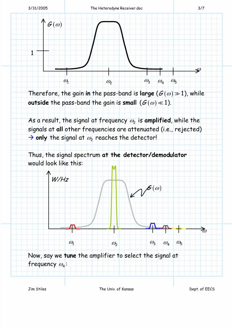
Therefore, the gain in the pass-band is large ( ( ) 1G ω ), while
outside the pass-band the gain is small ( ( ) 1G ω ).
As a result, the signal at frequency 2ω is amplified, while the
signals at all other frequencies are attenuated (i.e., rejected)
only the signal at 2ω reaches the detector!
Thus, the signal spectrum at the detector/demodulator
would look like this:
Now, say we tune the amplifier to select the signal at
frequency 4ω :
ω
1ω 2ω 3ω
4ω 5ω
( )G ω
1
ω
1ω 2ω 3ω
4ω 5ω
W/Hz
( )G ω
8/3/2019 The Heterodyne Receiver
http://slidepdf.com/reader/full/the-heterodyne-receiver 4/7
3/31/2005 The Heterodyne Receiver.doc 4/7
Jim Stiles The Univ. of Kansas Dept. of EECS
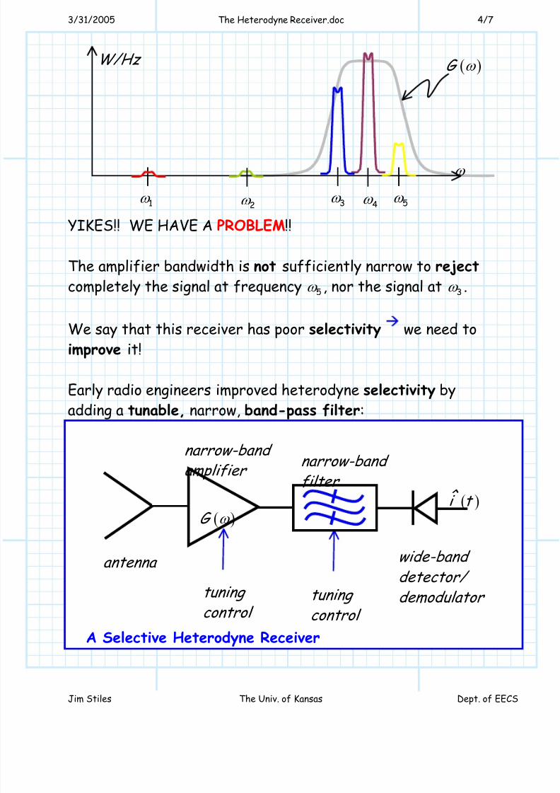
YIKES!! WE HAVE A PROBLEM!!
The amplifier bandwidth is not sufficiently narrow to reject
completely the signal at frequency 5ω , nor the signal at 3ω .
We say that this receiver has poor selectivity we need to
improve it!
Early radio engineers improved heterodyne selectivity by
adding a tunable, narrow, band-pass filter:
ω
1ω 2ω 3ω
4ω 5ω
W/Hz ( )G ω
( )G ω
( )ˆ i t
wide-band detector/ demodulator tuning
control
narrow-band amplifier
antenna
narrow-band
filter
tuning control
A Selective Heterodyne Receiver
8/3/2019 The Heterodyne Receiver
http://slidepdf.com/reader/full/the-heterodyne-receiver 5/7
3/31/2005 The Heterodyne Receiver.doc 5/7
Jim Stiles The Univ. of Kansas Dept. of EECS
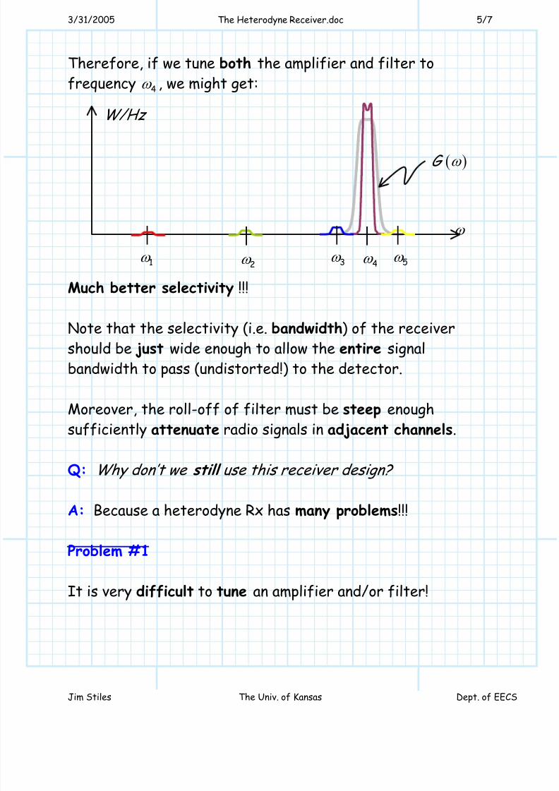
Therefore, if we tune both the amplifier and filter to
frequency 4ω , we might get:
Much better selectivity !!!
Note that the selectivity (i.e. bandwidth) of the receiver
should be just wide enough to allow the entire signal
bandwidth to pass (undistorted!) to the detector.
Moreover, the roll-off of filter must be steep enoughsufficiently attenuate radio signals in adjacent channels.
Q: Why don’t we still use this receiver design?
A: Because a heterodyne Rx has many problems!!!
Problem #1
It is very difficult to tune an amplifier and/or filter!
ω
1ω 2ω 3ω
4ω 5ω
W/Hz
( )G ω
8/3/2019 The Heterodyne Receiver
http://slidepdf.com/reader/full/the-heterodyne-receiver 6/7
3/31/2005 The Heterodyne Receiver.doc 6/7
Jim Stiles The Univ. of Kansas Dept. of EECS
* We change the frequency response of an amplifier/filter by
changing the values of the reactive components (i.e.,
inductors and capacitors).
* But, the center frequency and bandwidth of anamplifier/filter are related to the inductor and capacitor
values in very indirect and complex ways.
* Additionally, a filter of high selectivity (i.e., “fast roll-off”
) will be a filter of high order high order means many
inductors and capacitors!
Result: Tuning a good heterodyne receiver can be very
difficult, requiring a precise adjustment of many control
knobs!
Problem #2
The signal reaching the detector can be any one of many
frequencies (e.g., 1 2 3 4, , ,ω ω ω ω ) distributed across a very wide
bandwidth.
As a result, the detector must be wideband!
Unfortunately we find that a good widebanddetector/demodulator is difficult to build. Generally
speaking, a detector/demodulator will work well at some
frequencies, but less well at others.
Q: So how do we fix these problems??
8/3/2019 The Heterodyne Receiver
http://slidepdf.com/reader/full/the-heterodyne-receiver 7/7
3/31/2005 The Heterodyne Receiver.doc 7/7
Jim Stiles The Univ. of Kansas Dept. of EECS
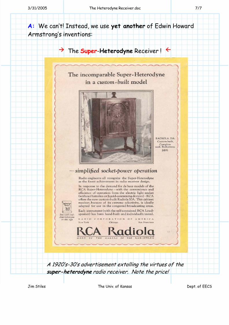
A: We can’t! Instead, we use yet another of Edwin Howard
Armstrong’s inventions:
The Super-Heterodyne Receiver !
A 1920’s-30’s advertisement extolling the virtues of the
super-heterodyne radio receiver. Note the price!