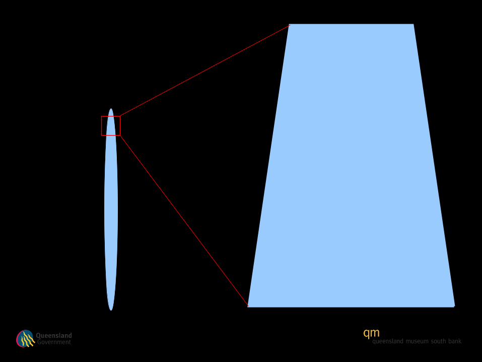
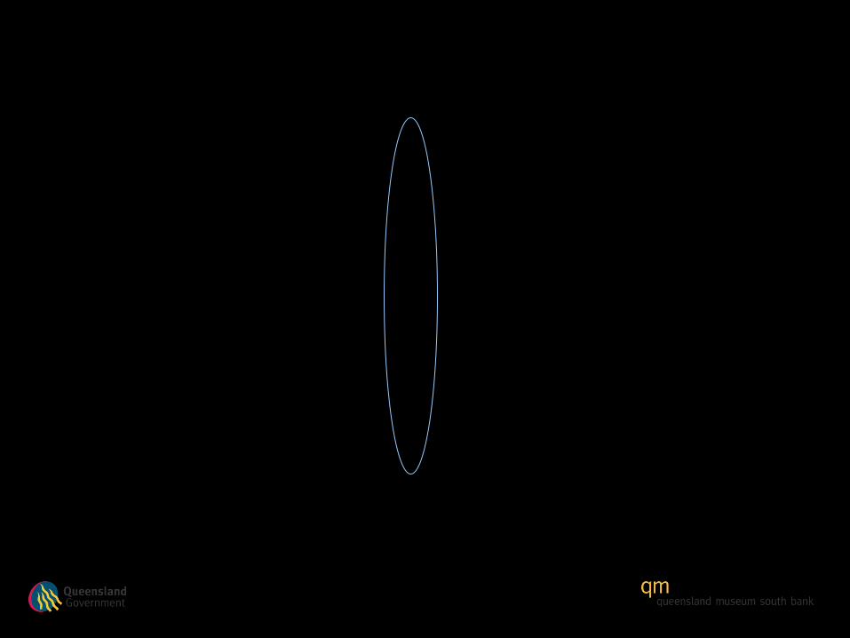
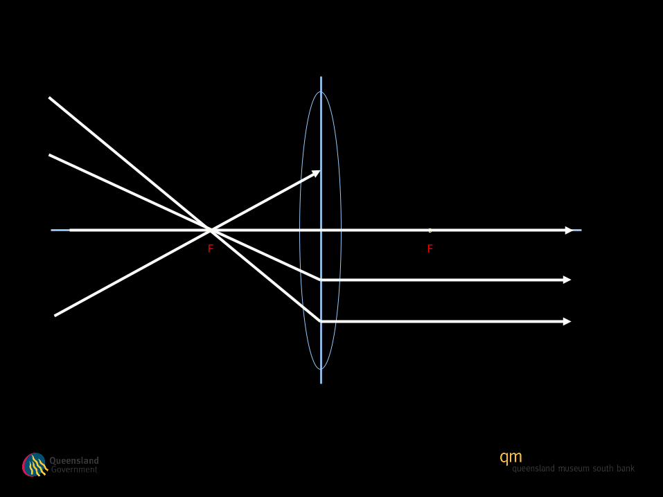
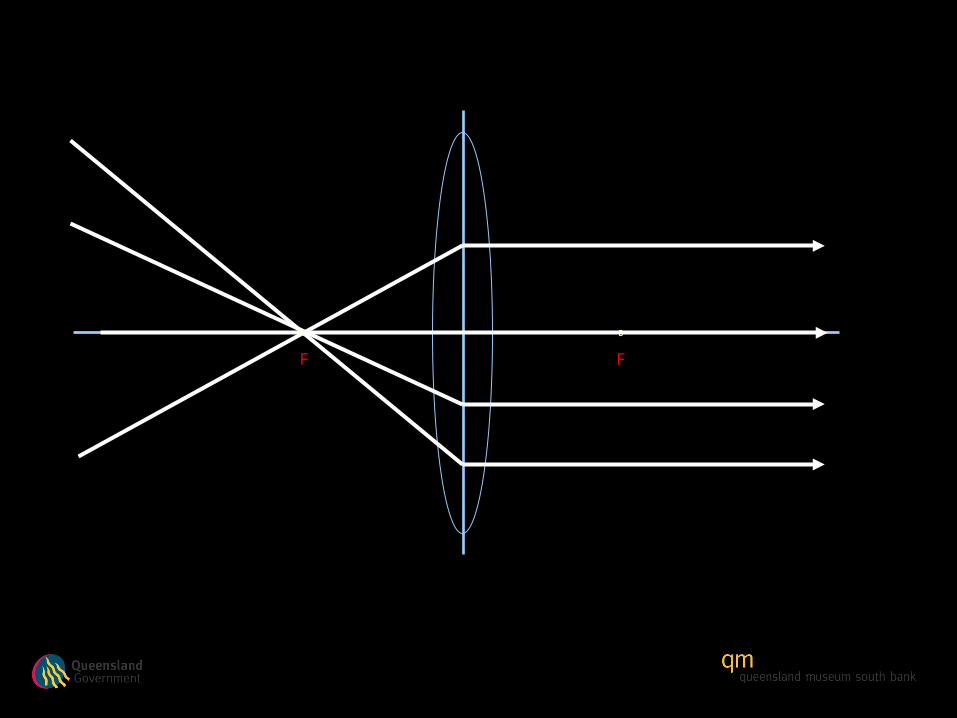
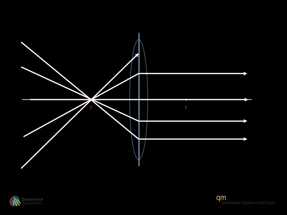
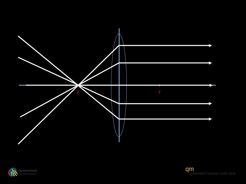
refraction of light through a convex lens. lens diagram a cross section through the centre plane
TRANSCRIPT
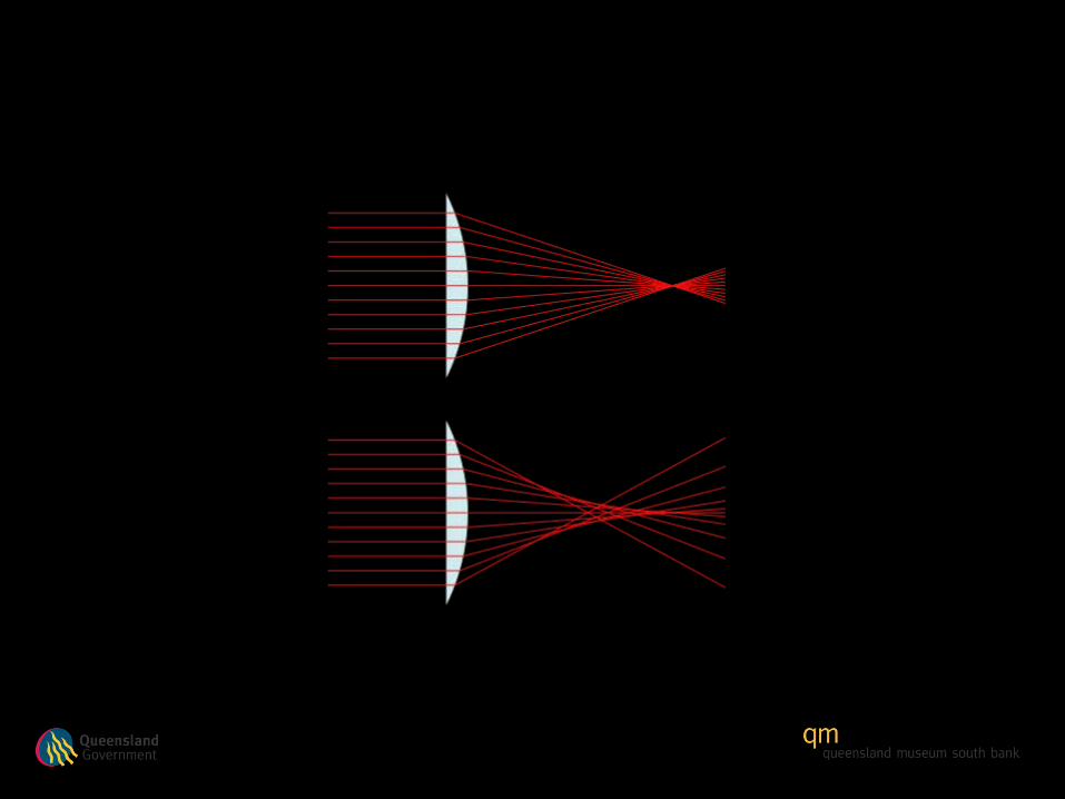
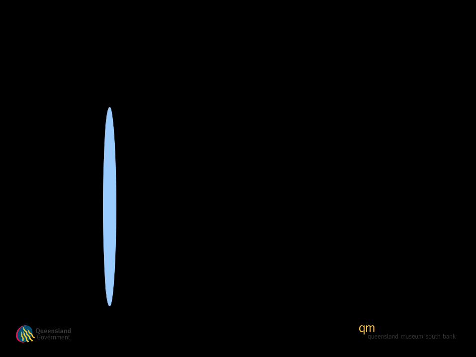
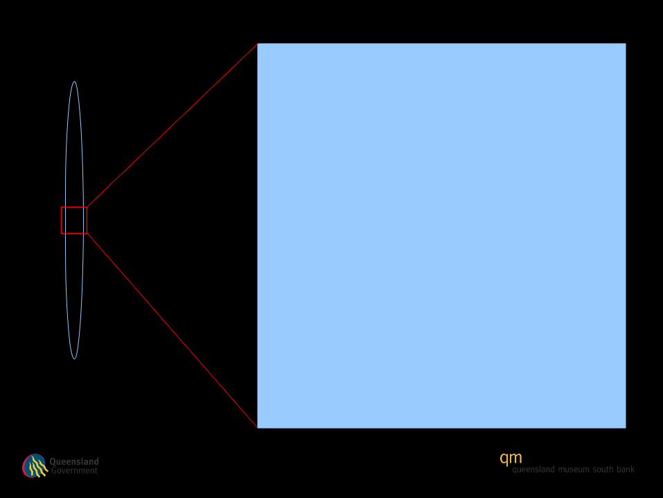
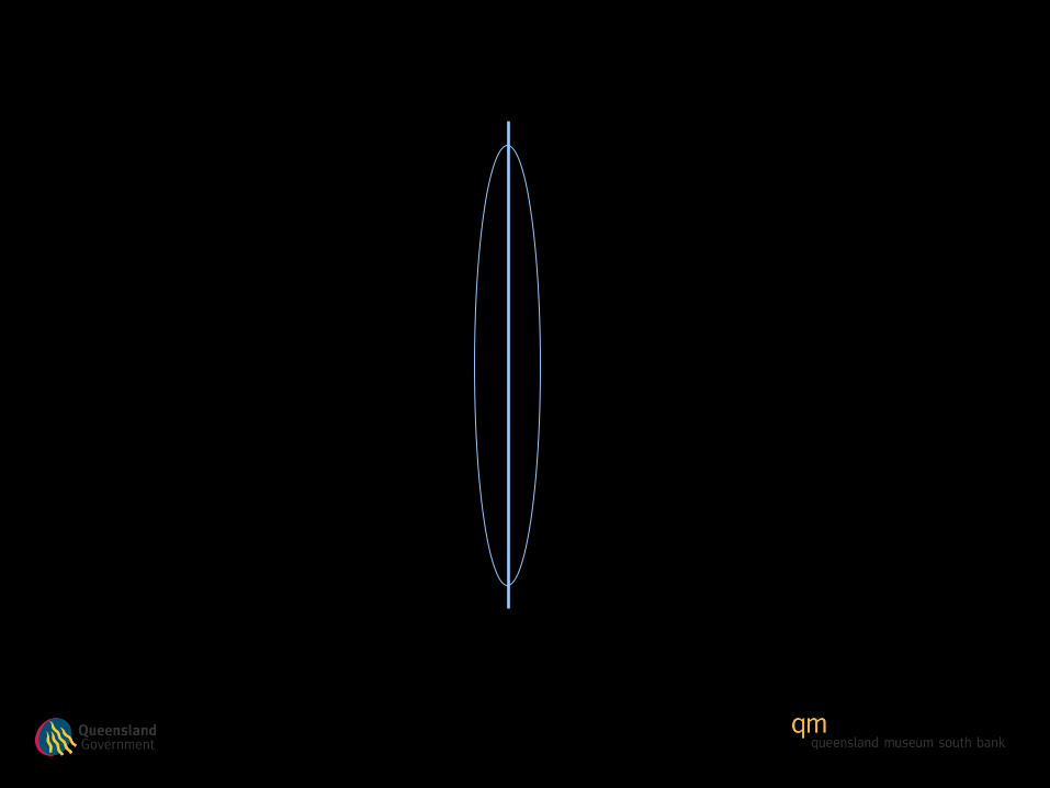
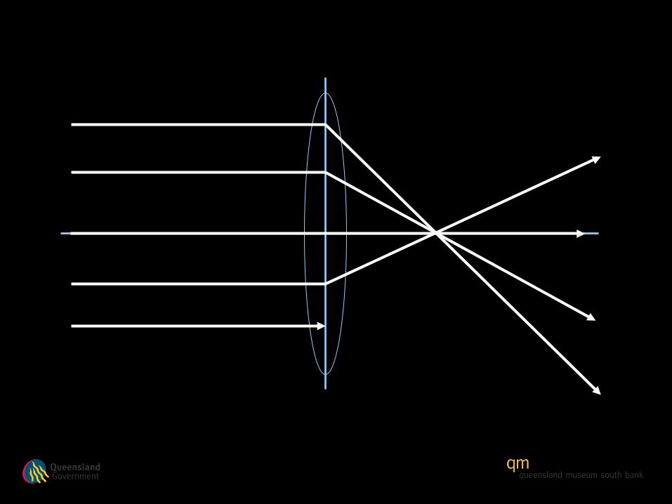
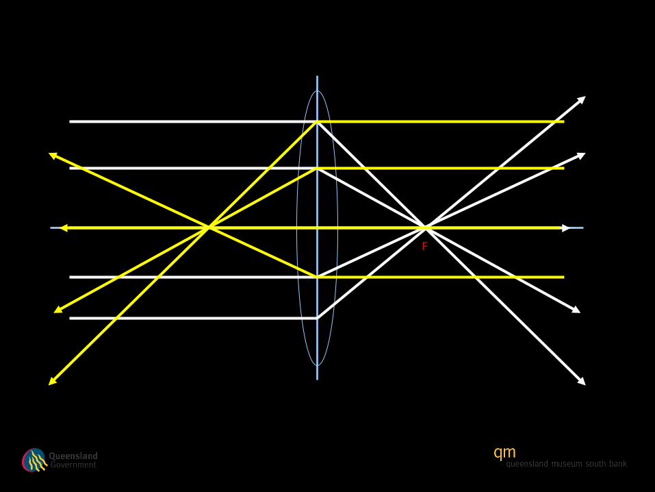
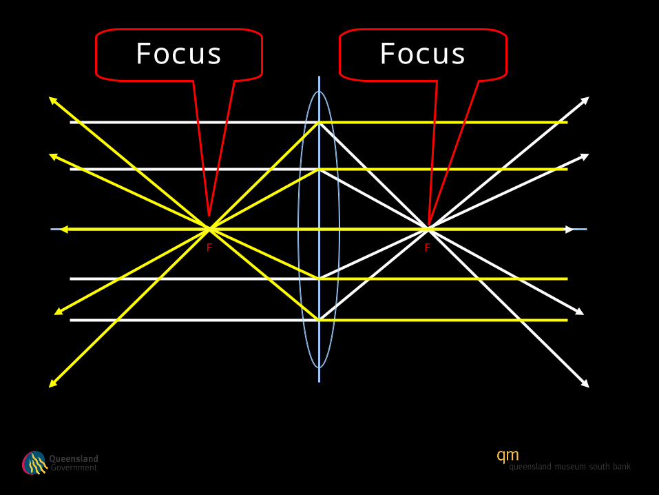
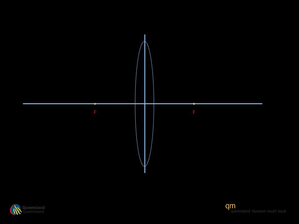
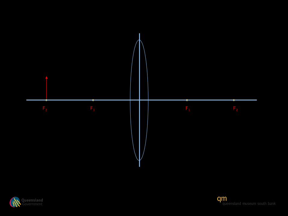
Refraction of light through a Convex Lens
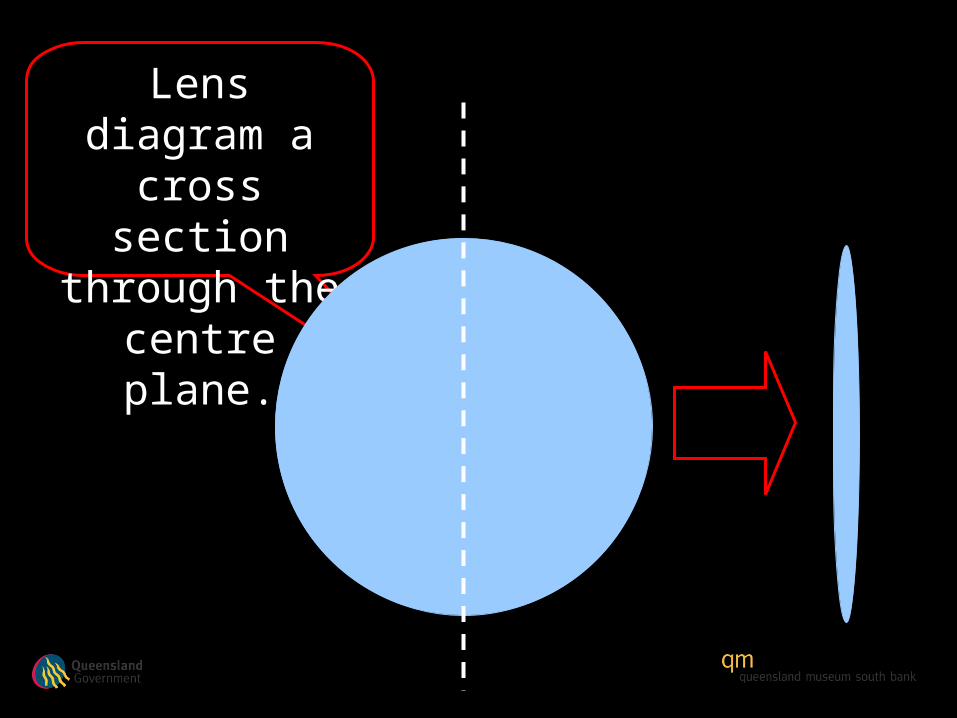
Lens diagram a cross section through the
centre plane.

Simple convex (curves outwards) lens
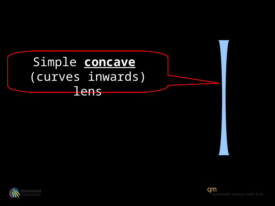
Simple concave (curves inwards) lens

Convex lens
Concave lens
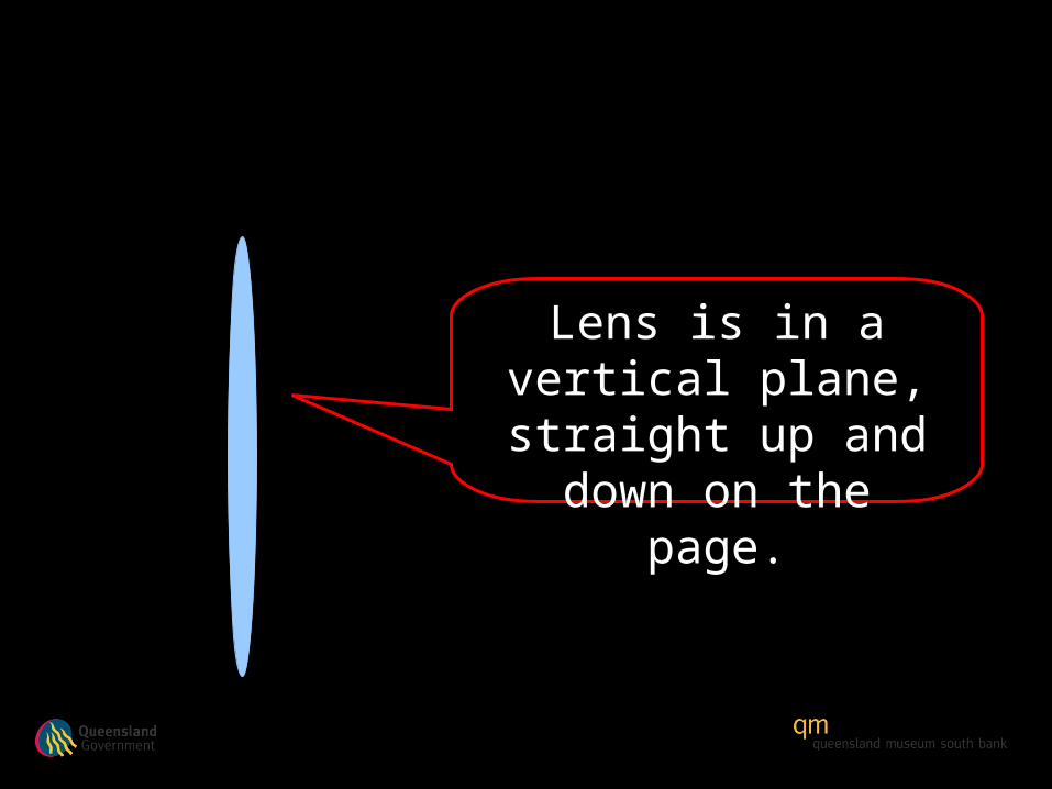
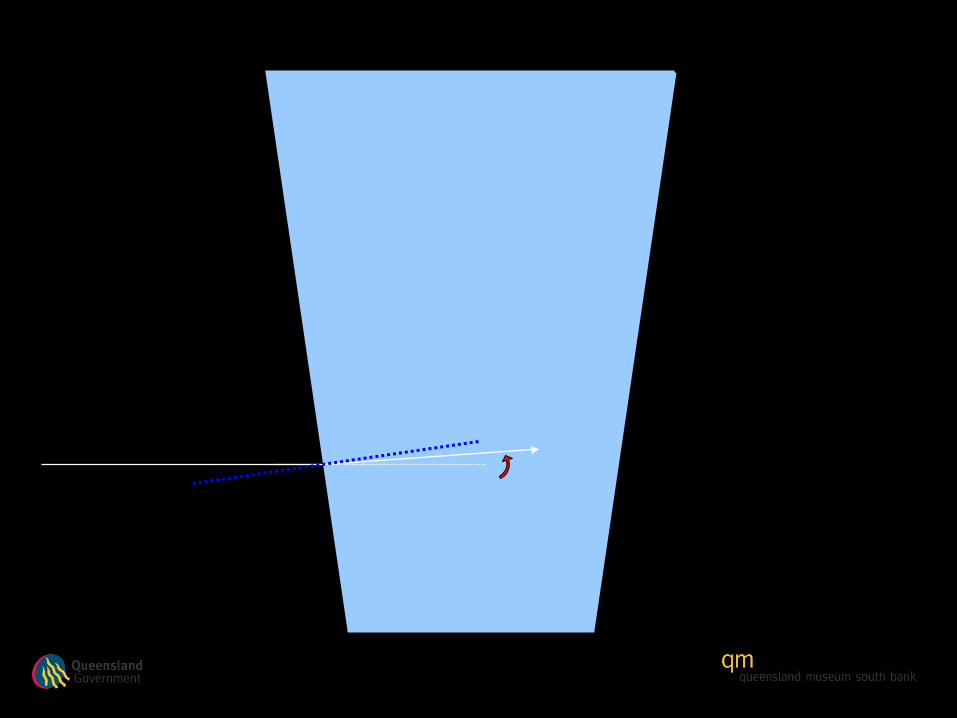
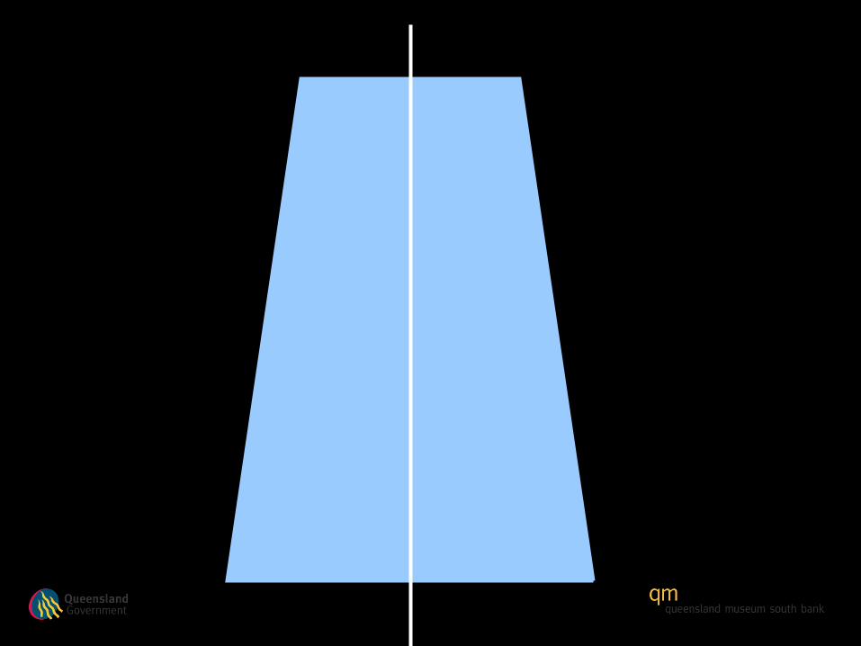
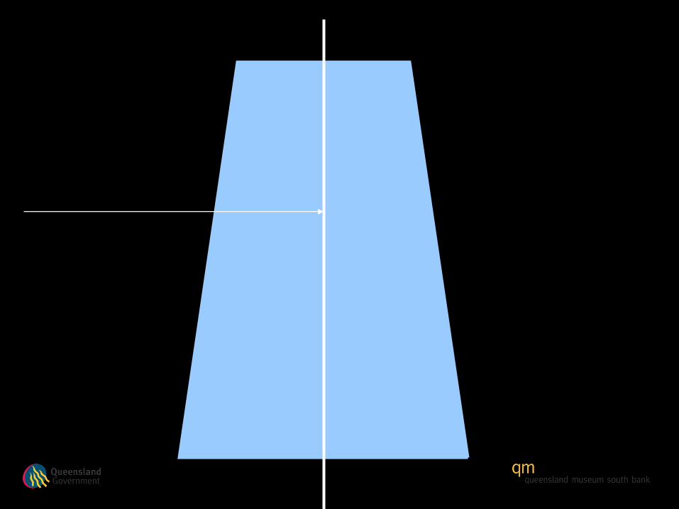
Lens is in a vertical plane, straight up and
down on the page.

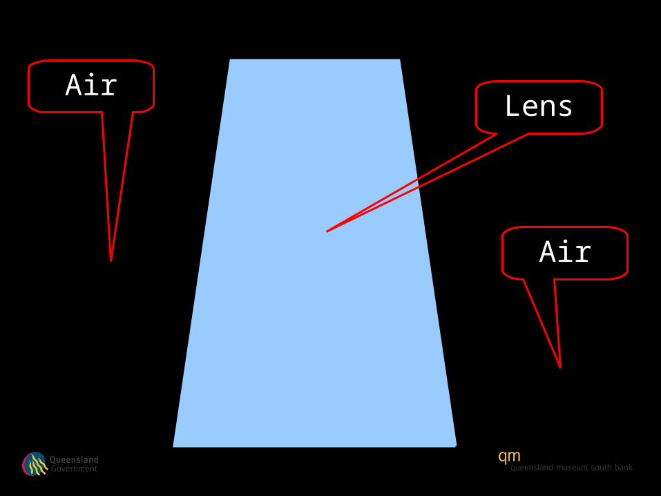
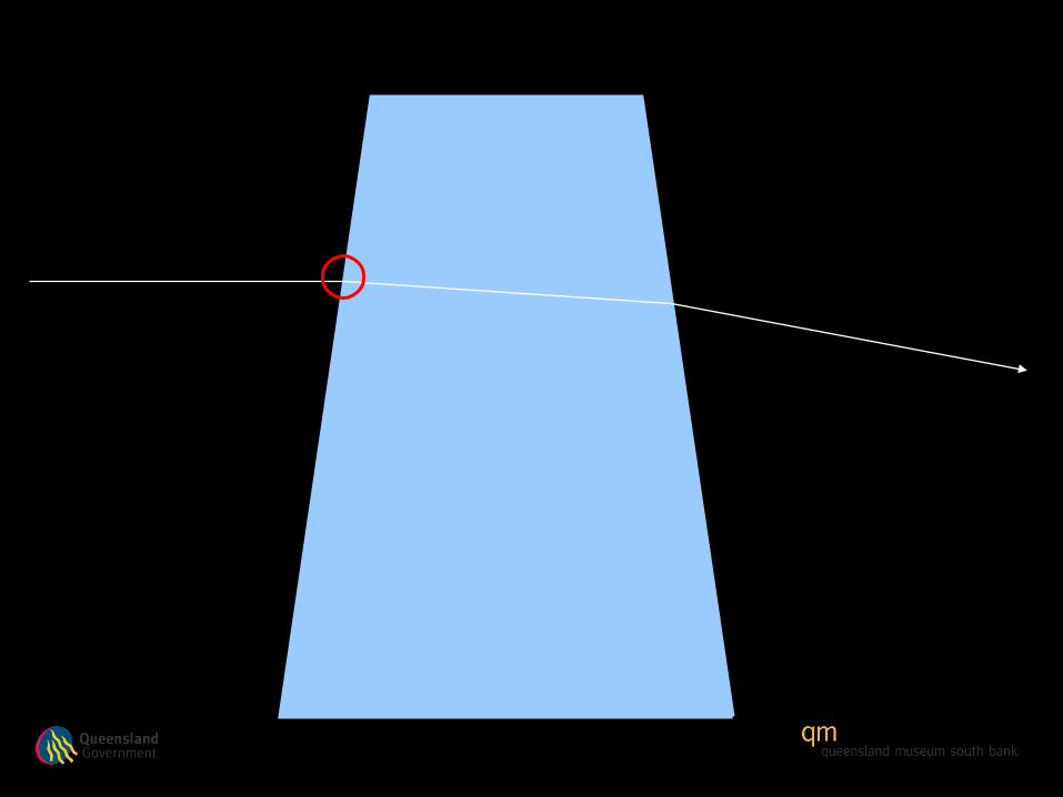
LensAir
Air

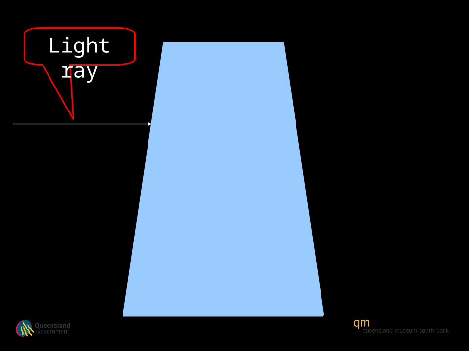
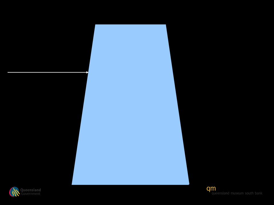
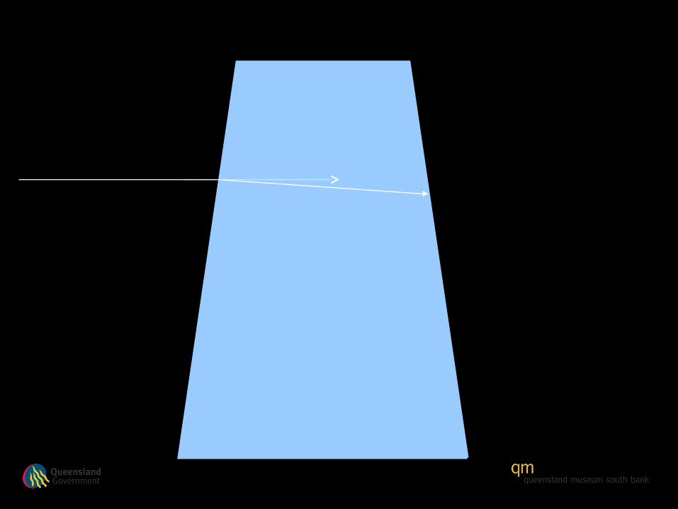
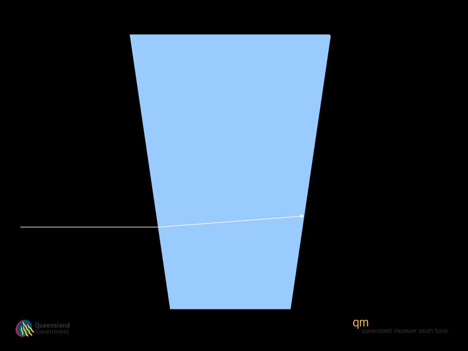
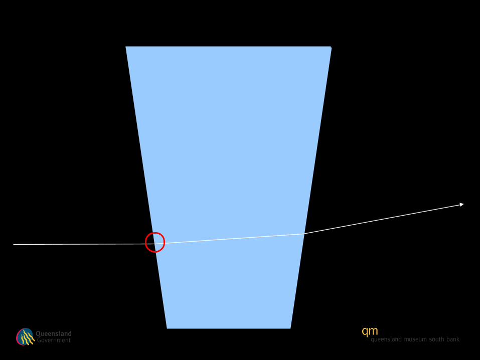
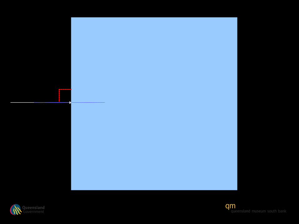
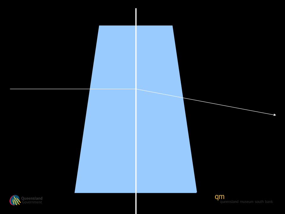
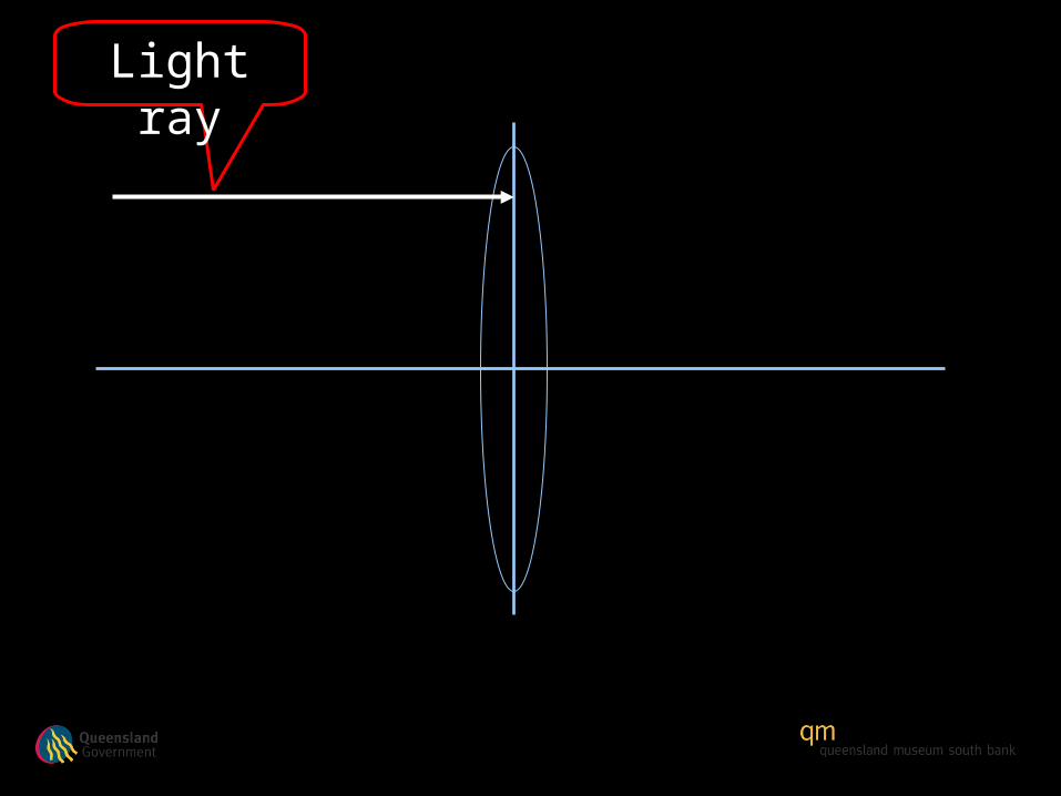
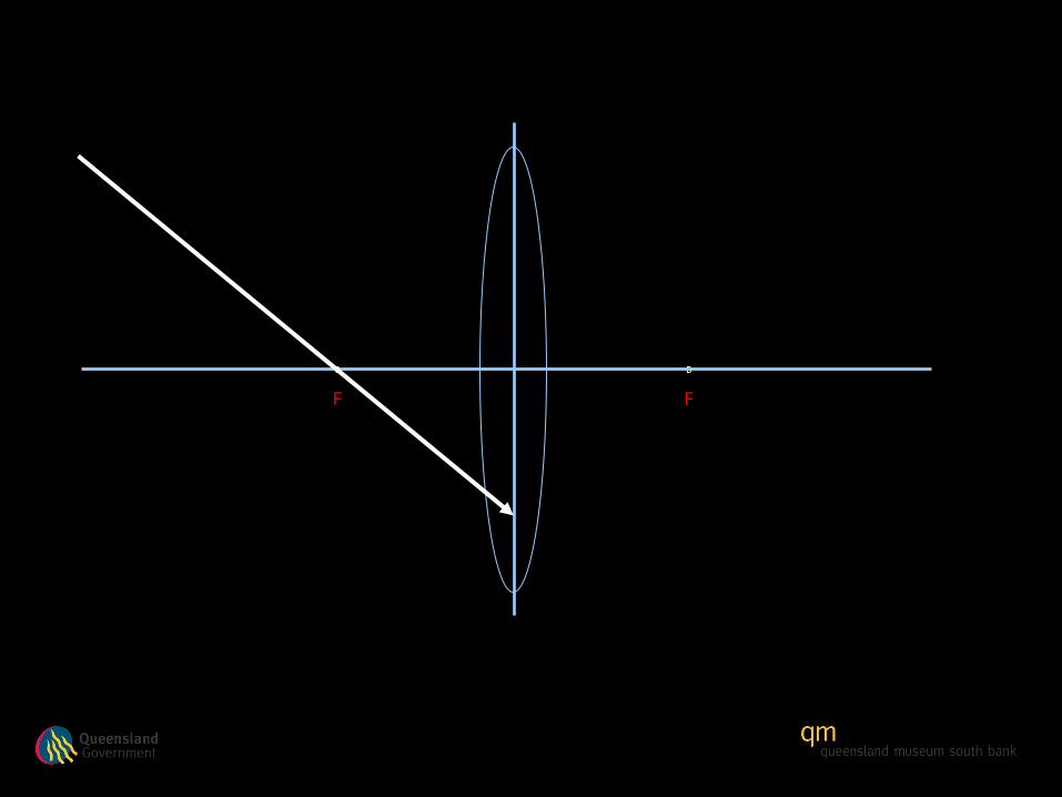
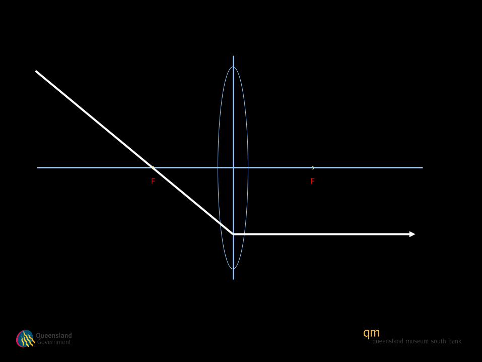
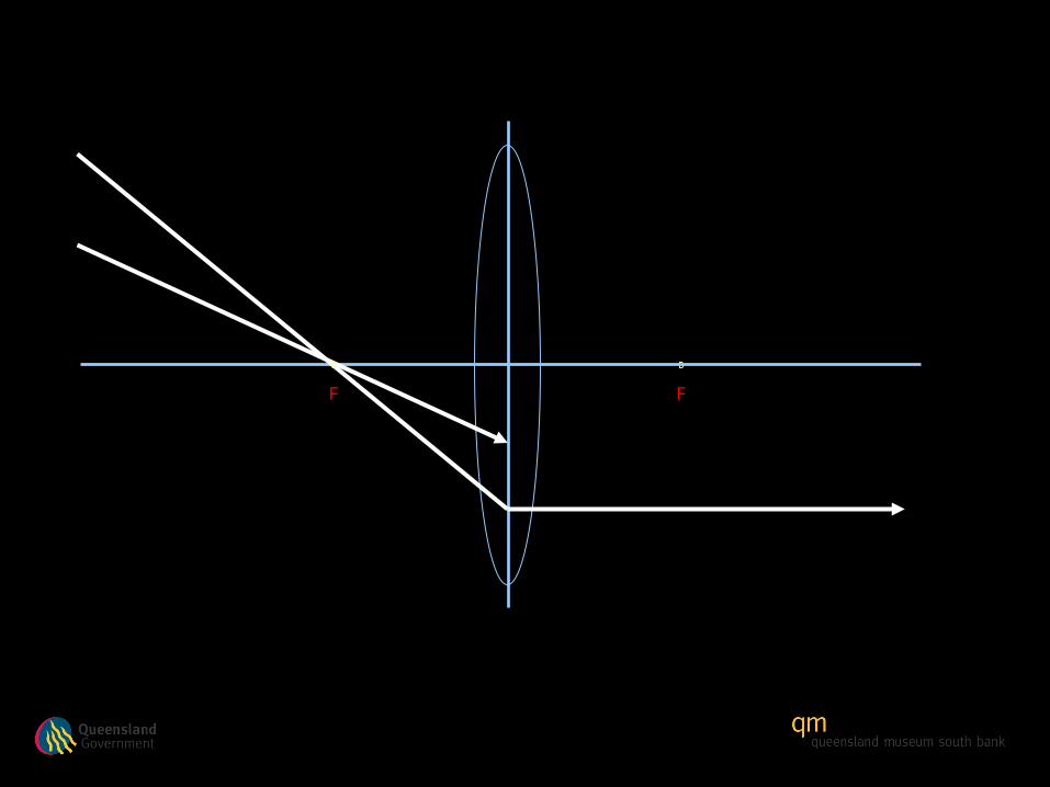
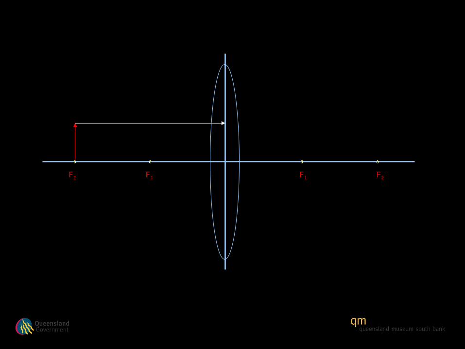
Light ray
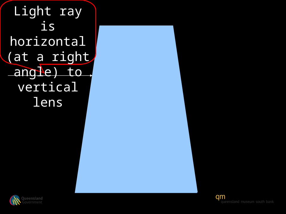
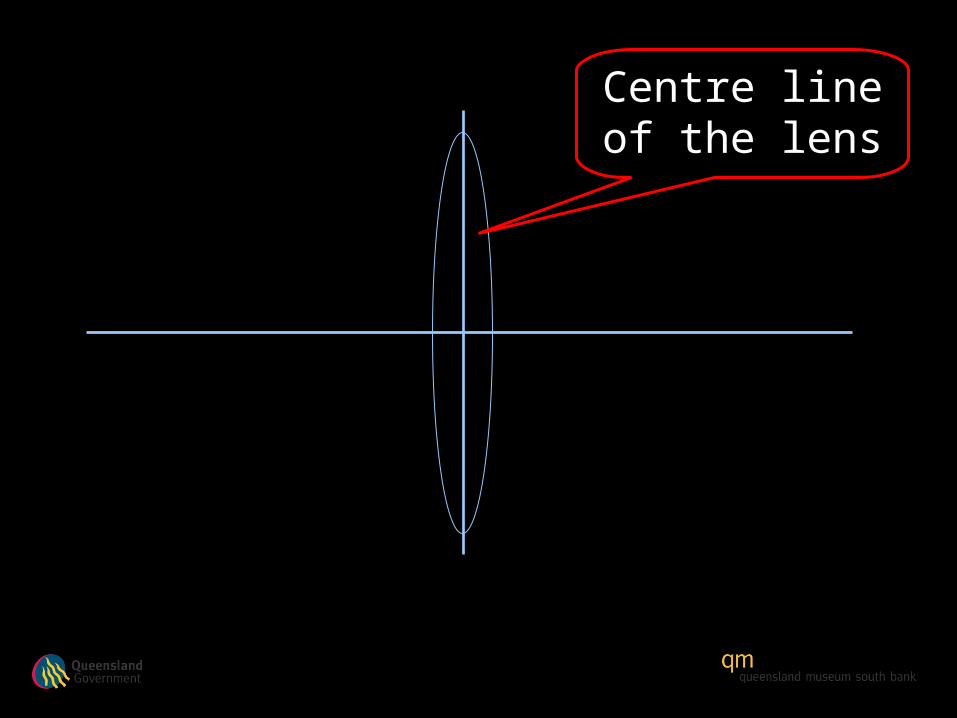
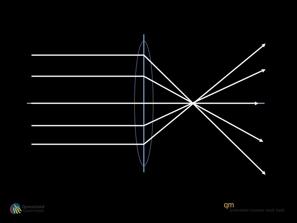
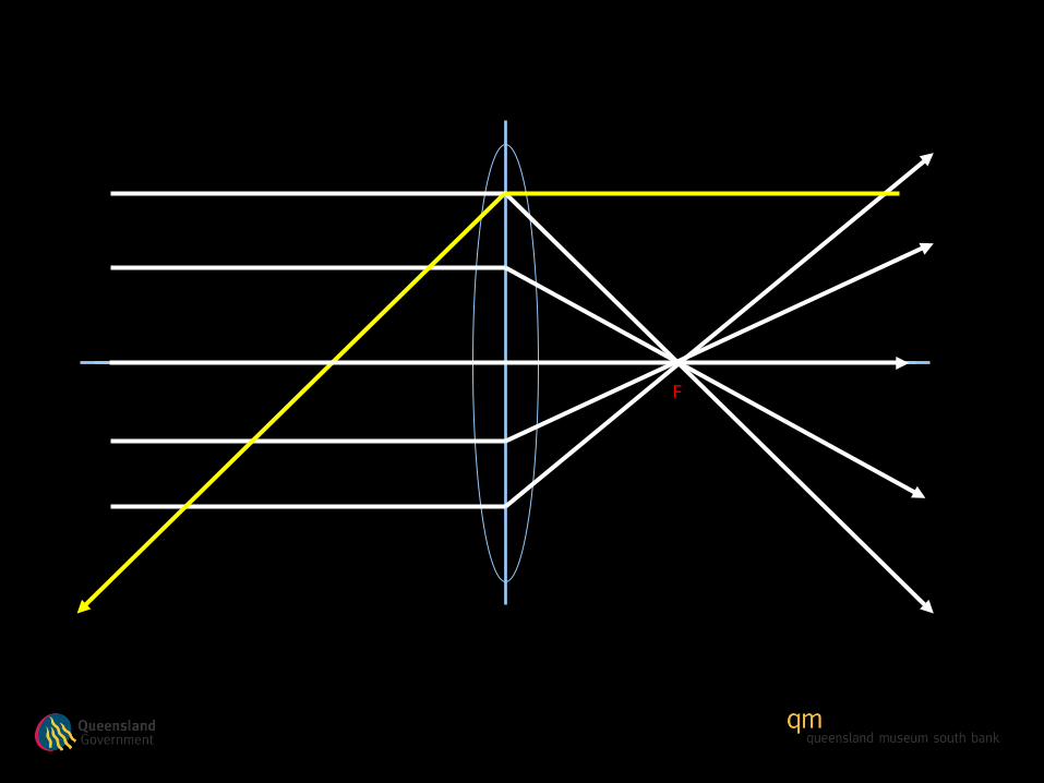
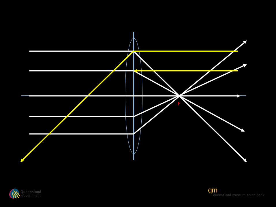
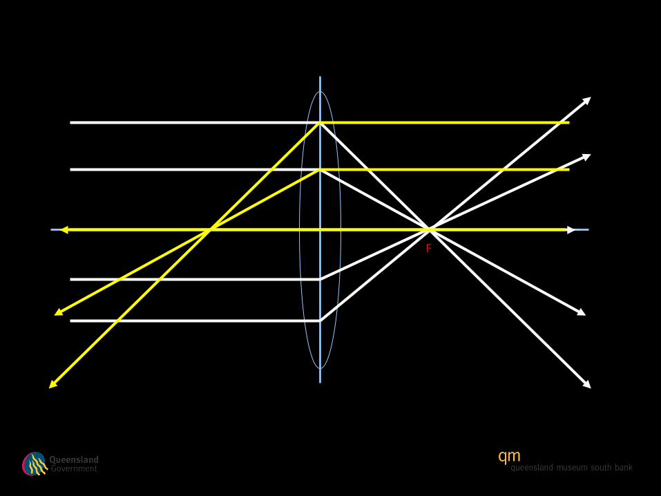
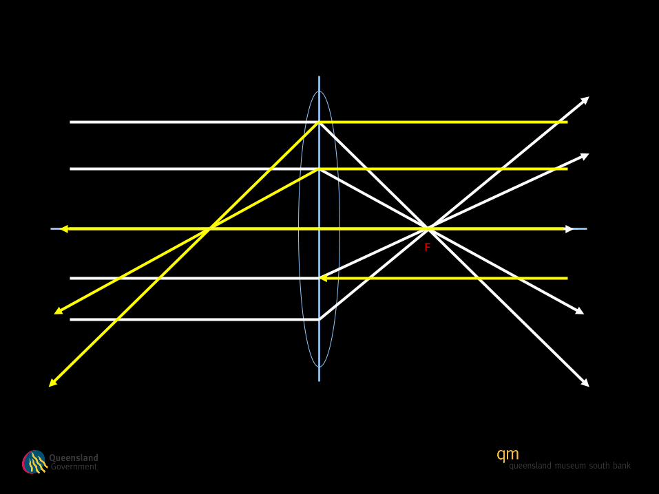
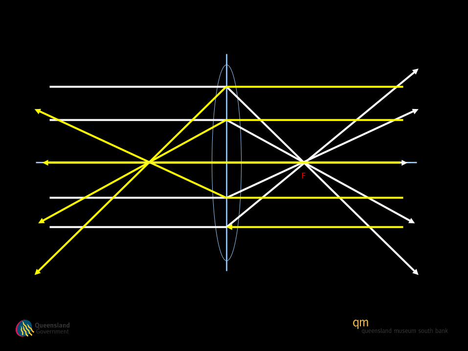
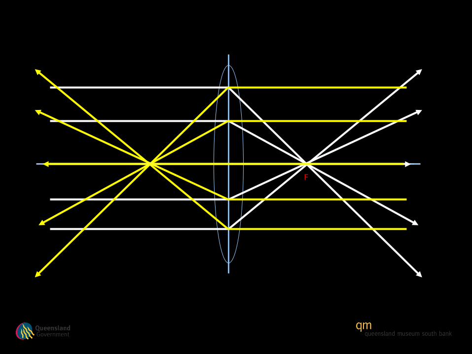
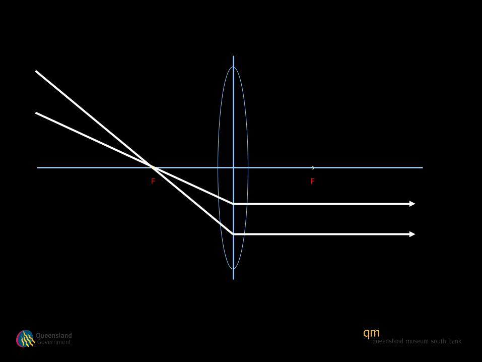
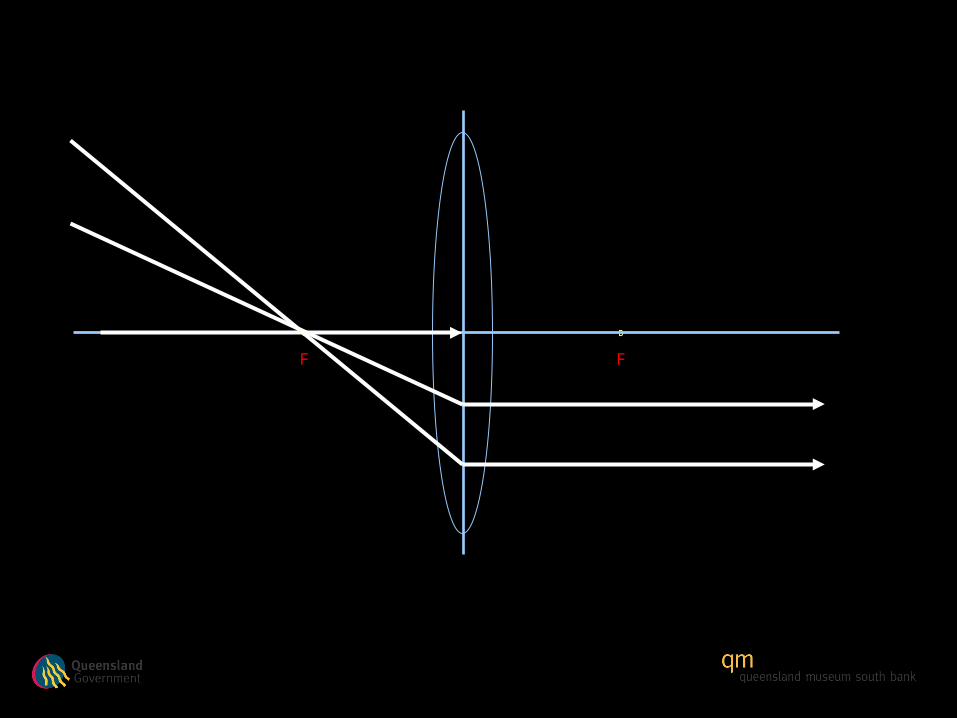
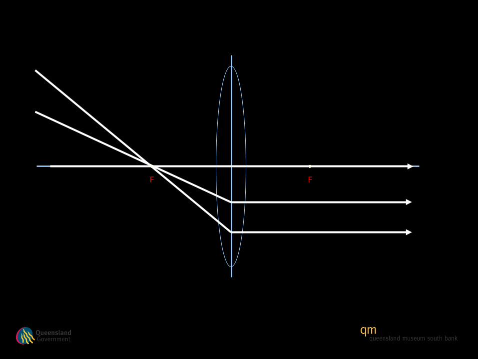
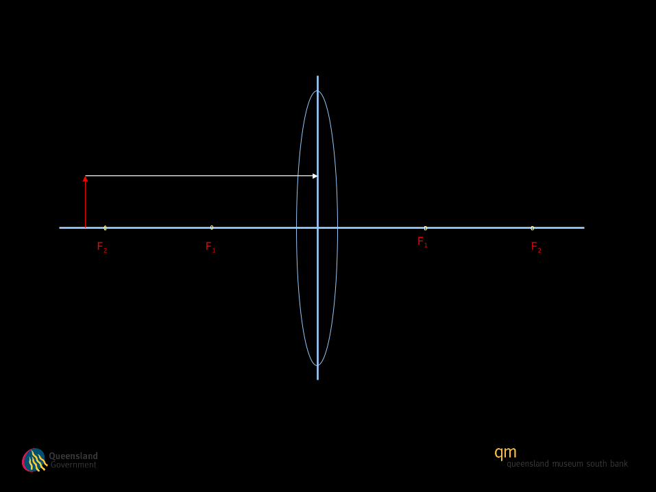
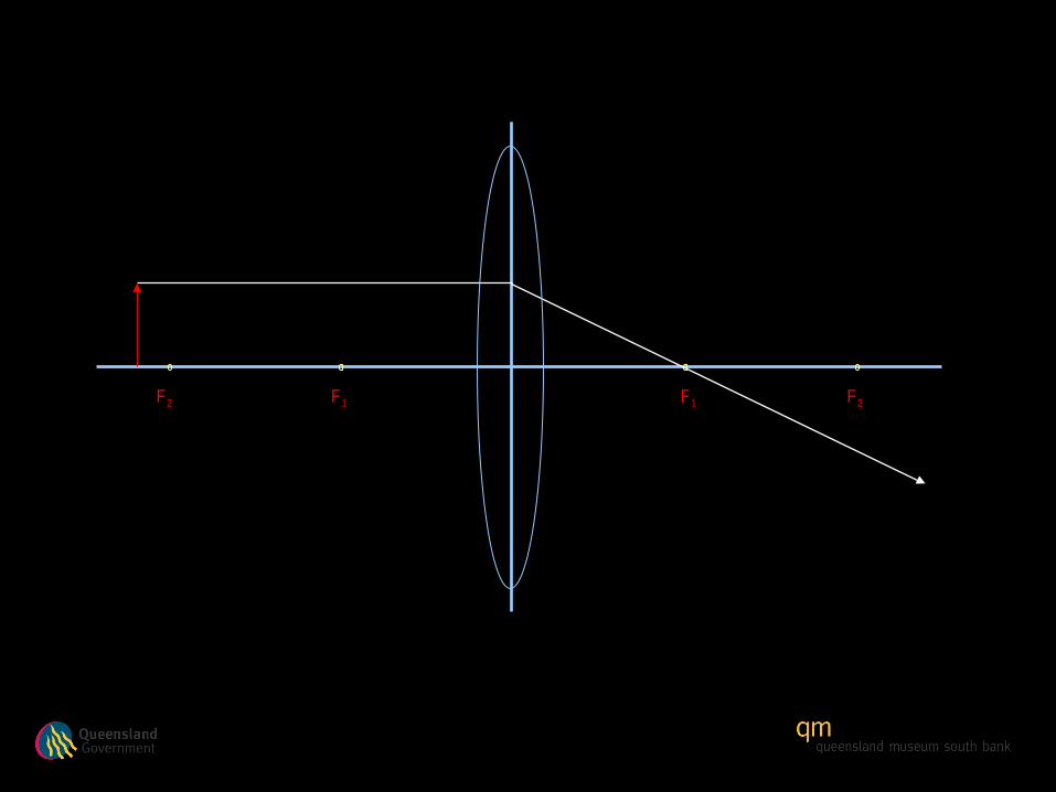
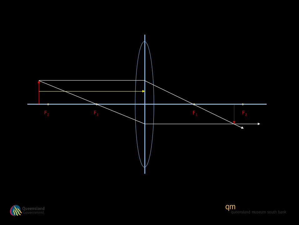
Light ray is horizontal (at a right angle) to vertical lens

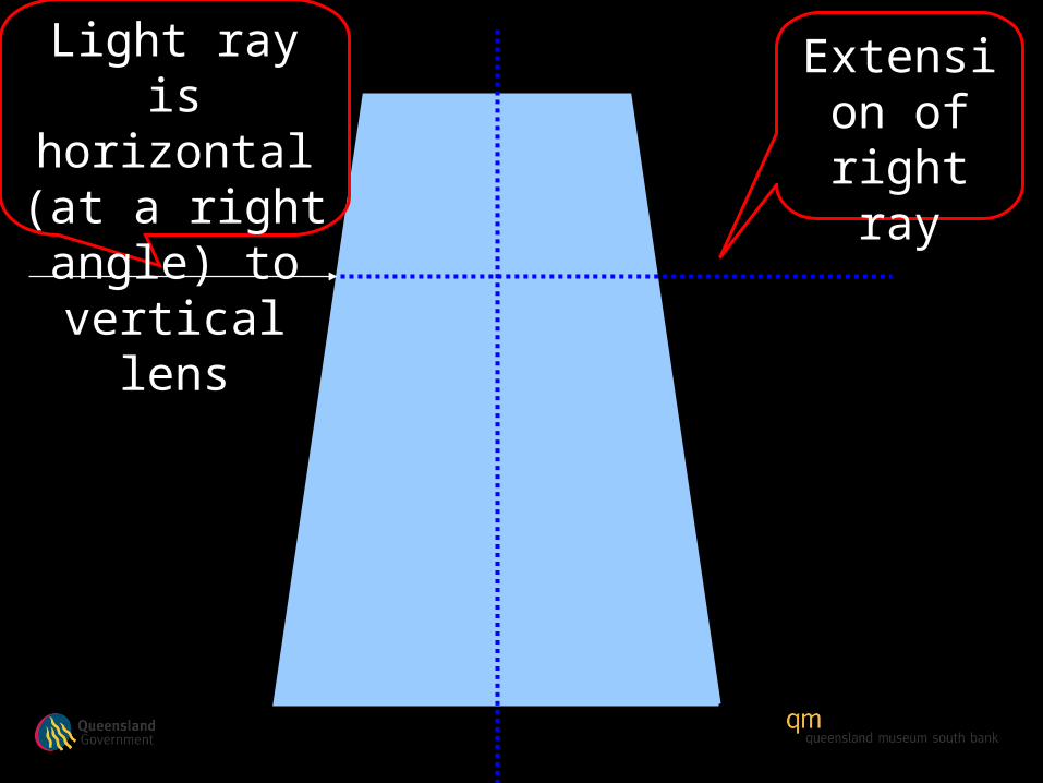
Light ray is horizontal (at a right angle) to vertical lens

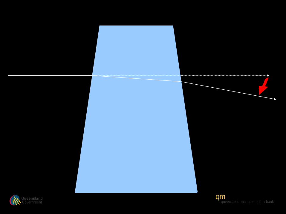
Extension of right
ray
Light ray is horizontal (at a right angle) to vertical lens
Extension of right
ray
Light ray is horizontal (at a right angle) to vertical lens
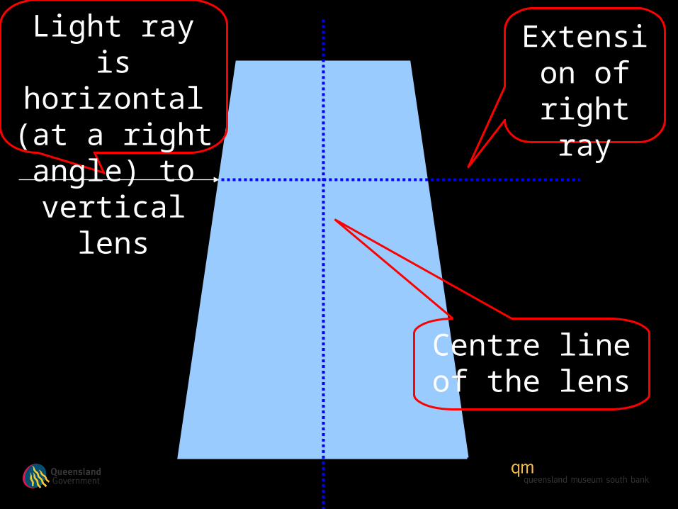
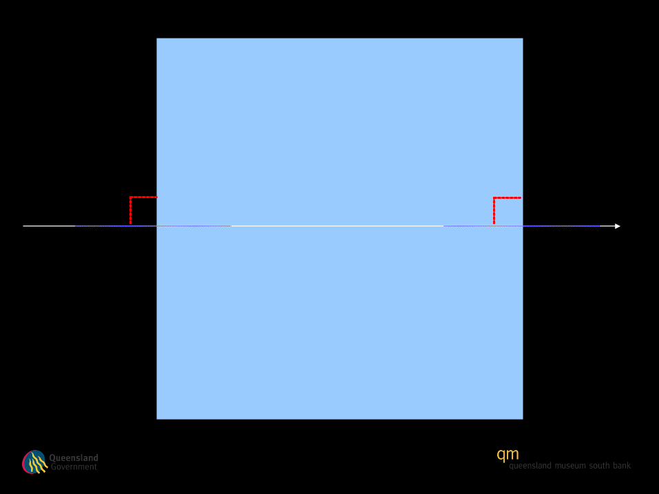
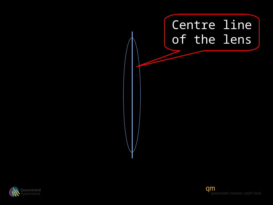
Centre line of the lens
Extension of right
ray
Light ray is horizontal (at a right angle) to vertical lens

Extension of right
ray
Light ray is horizontal (at a right angle) to vertical lens
Centre line of the lens
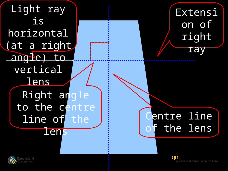
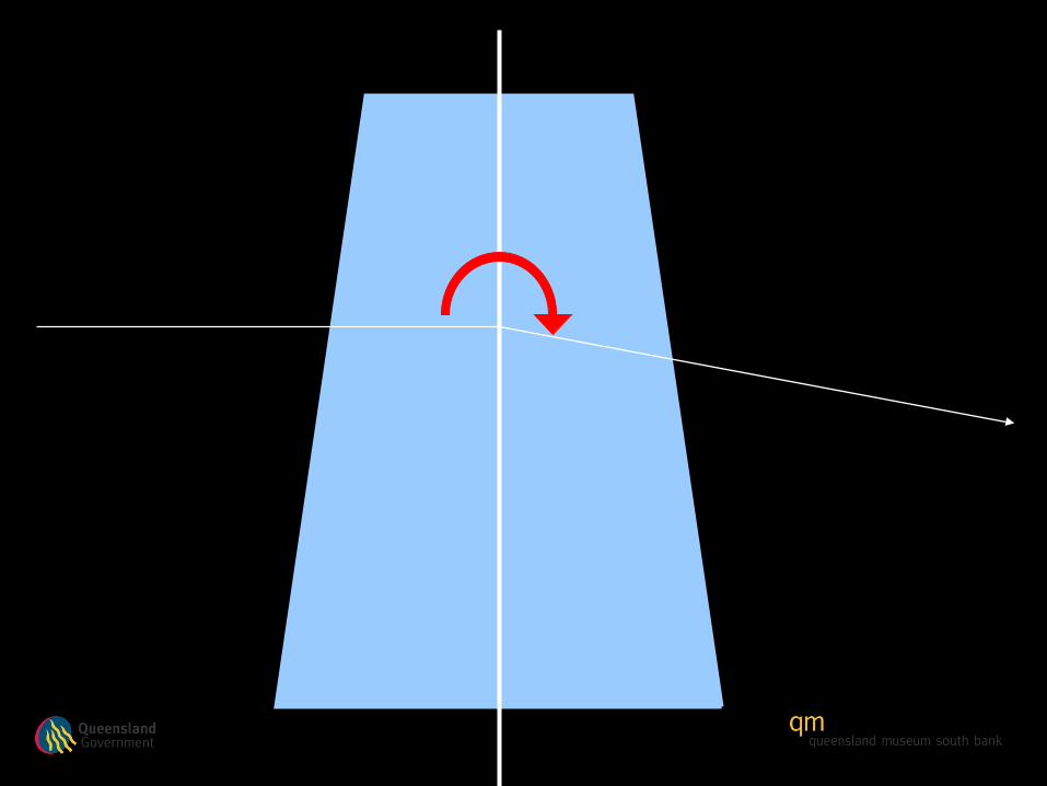
Right angle to the centre line of the
lens
Extension of right
ray
Light ray is horizontal (at a right angle) to vertical lens
Centre line of the lens


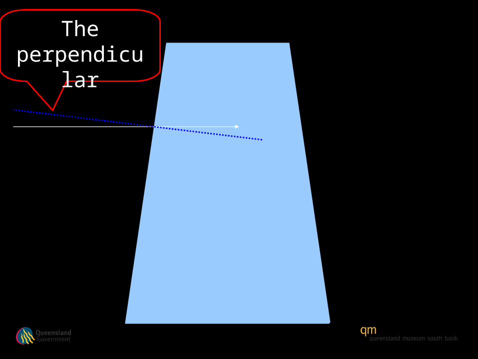
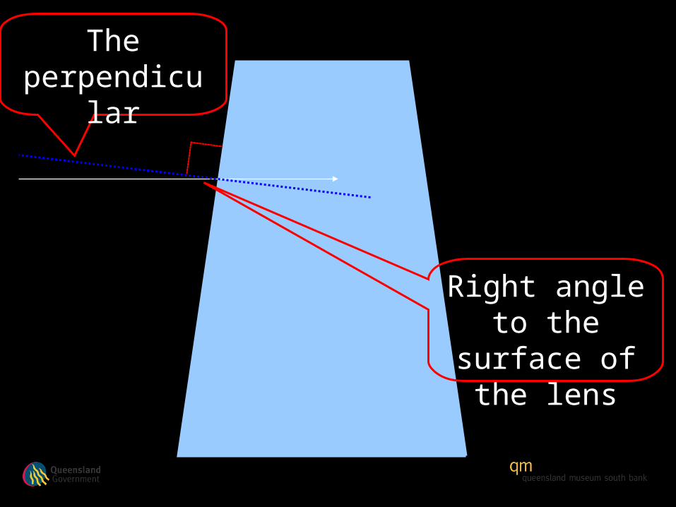
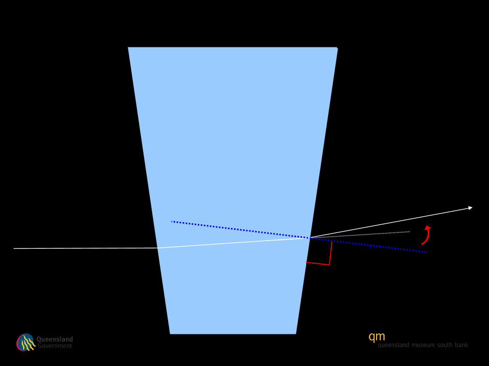
The perpendicular

The perpendicular
The perpendicular
Right angle to the surface of
the lens


Centre line of the lens
Centre line of the lens

Centre line of the lens
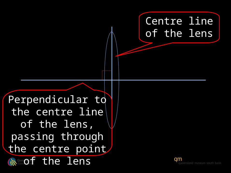
Perpendicular to the centre line of the
lens, passing through the centre point of the
lens
Centre line of the lens

Light ray

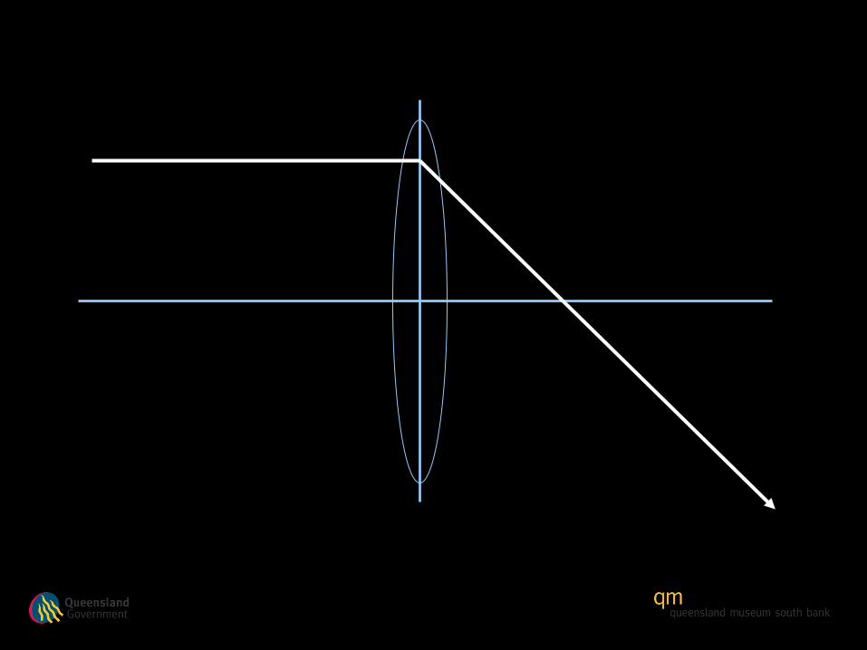
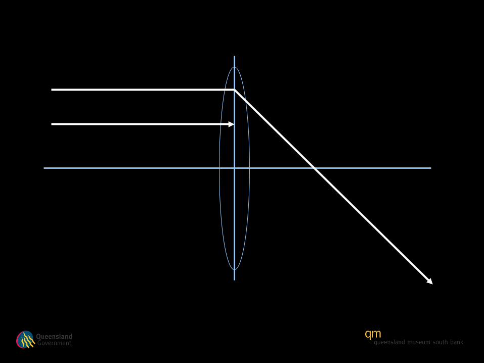
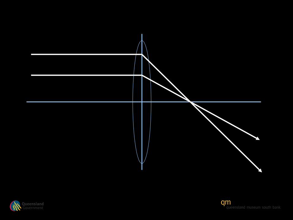
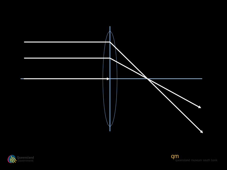
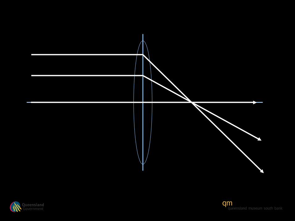
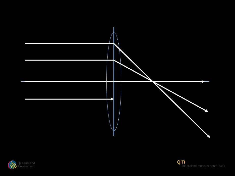
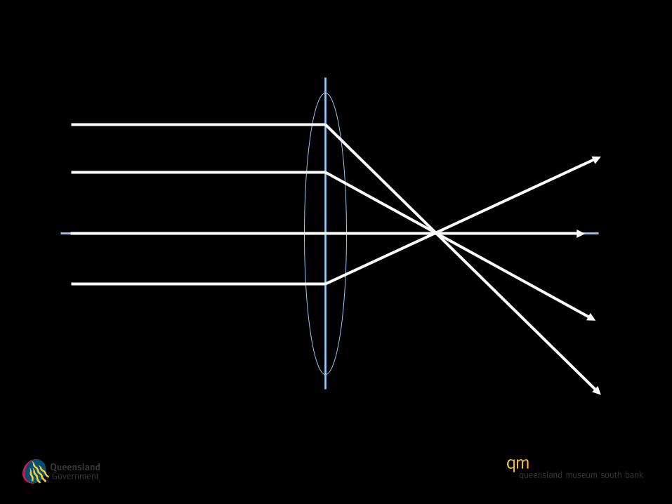
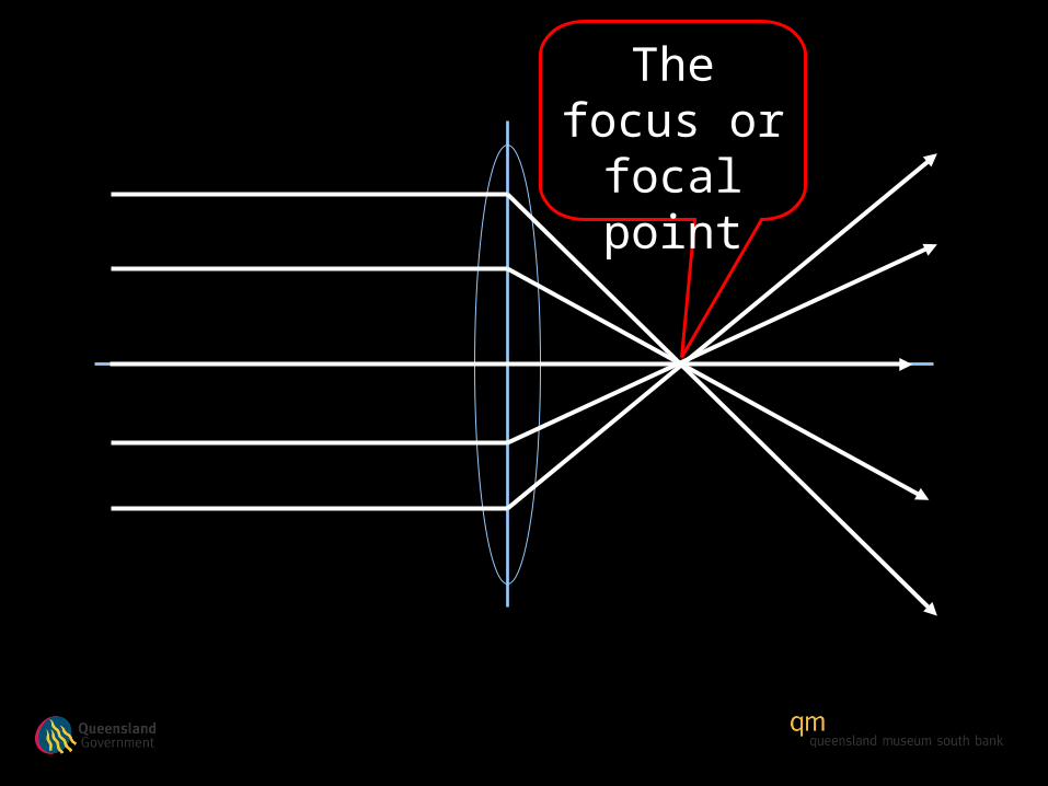
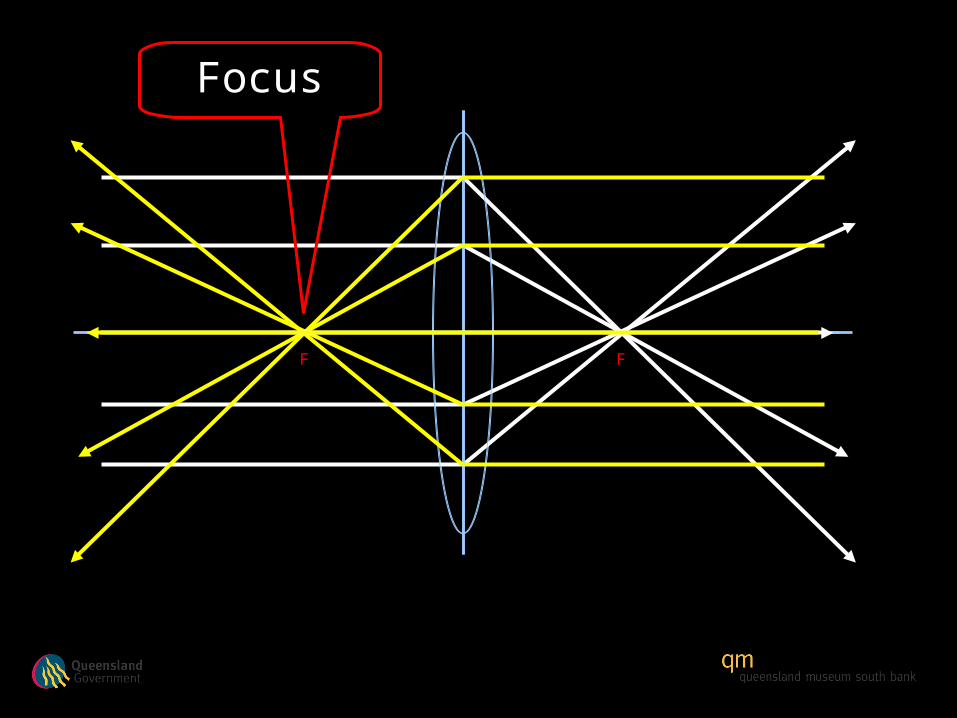
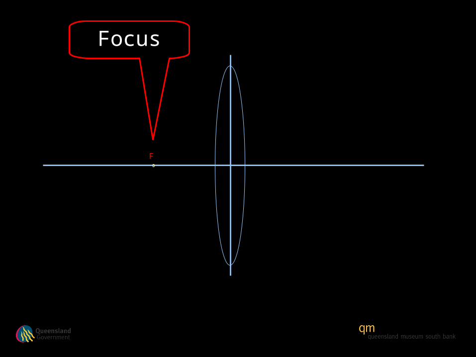
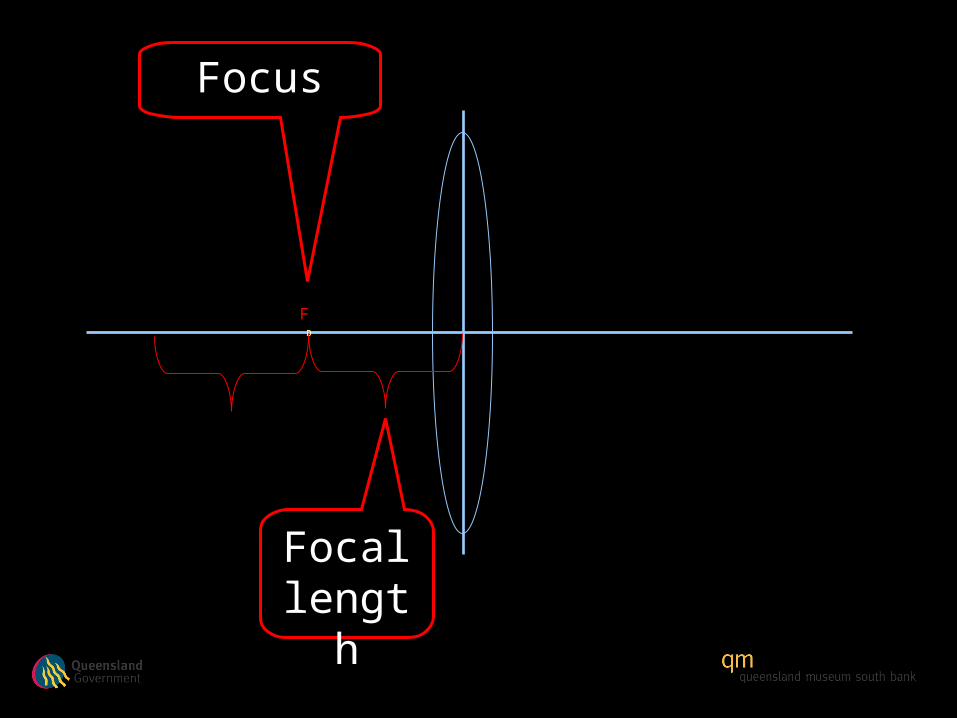
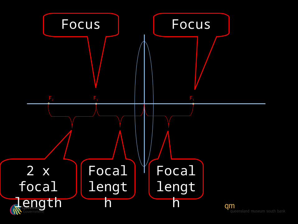
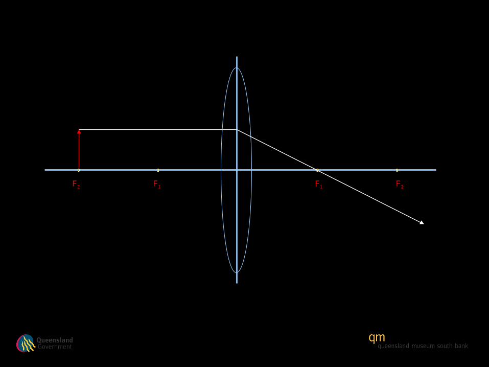
The focus or focal
point

F
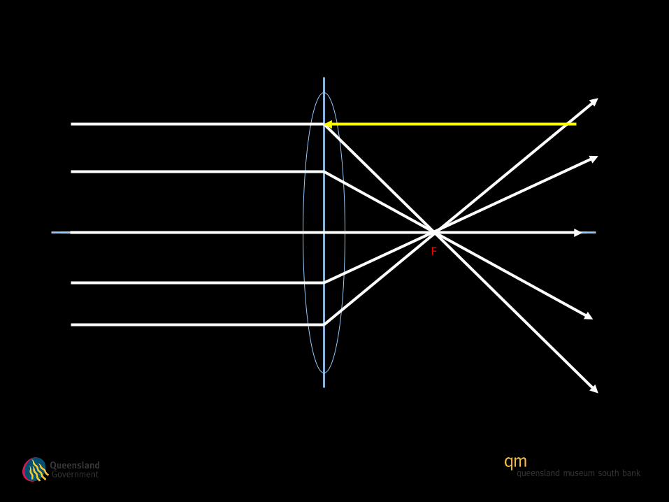
Focus
F
F
F

F

F
F
F
F
F
F
F F
Focus
F F
FocusFocus
F F
F F
F F
F F
F F
F F
F F
F F
F F
F F
F F


Focus
F
Focus
F
Focus

F
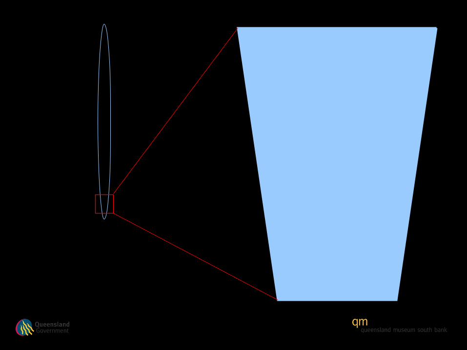
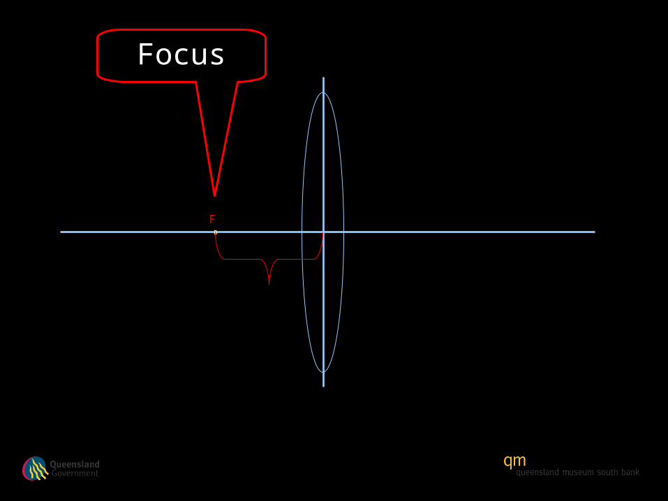
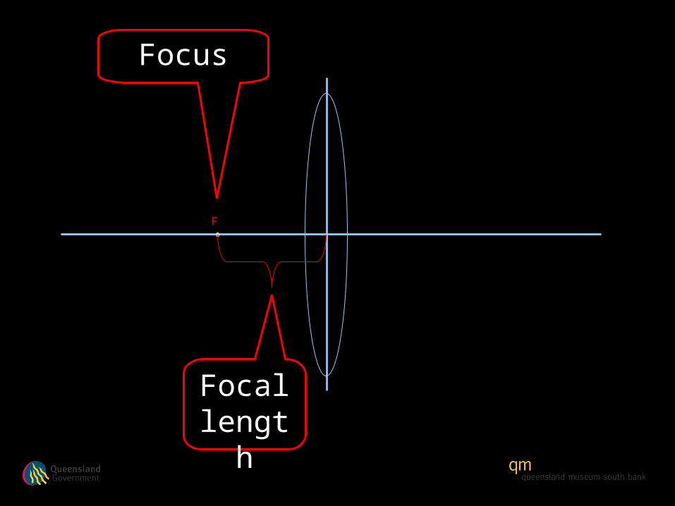
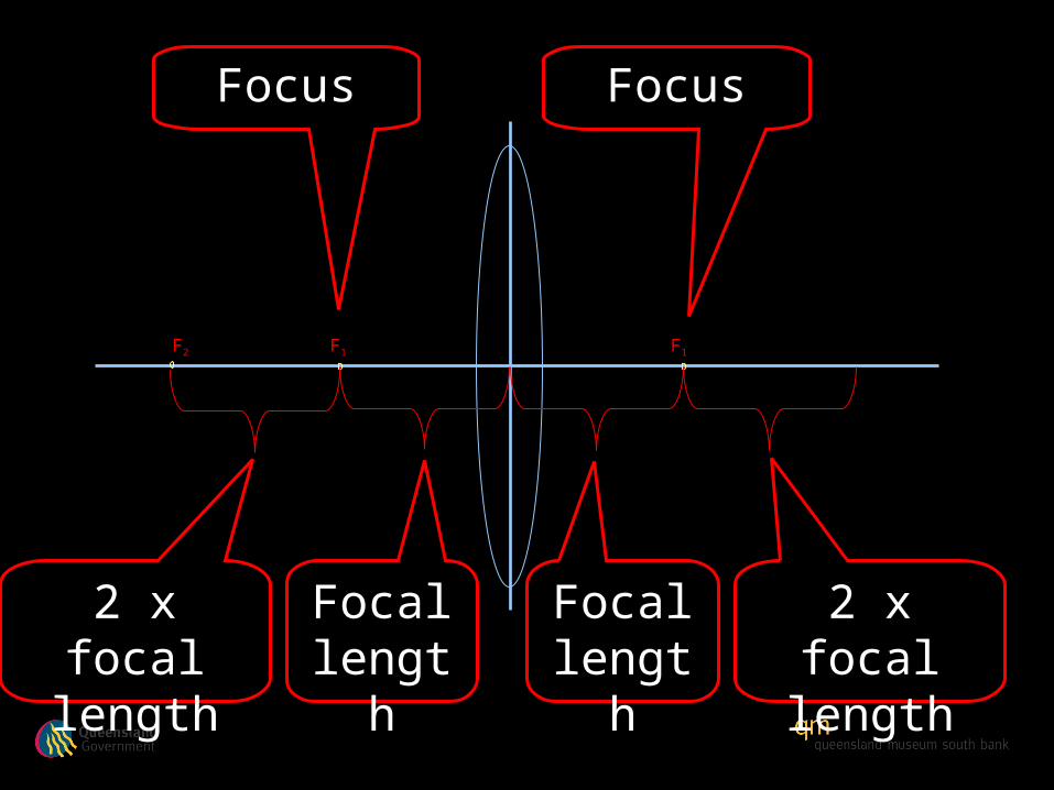
Focal length
Focus
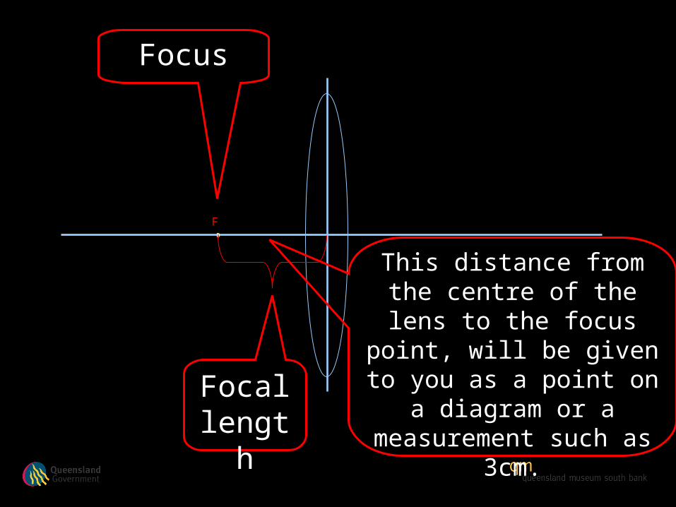
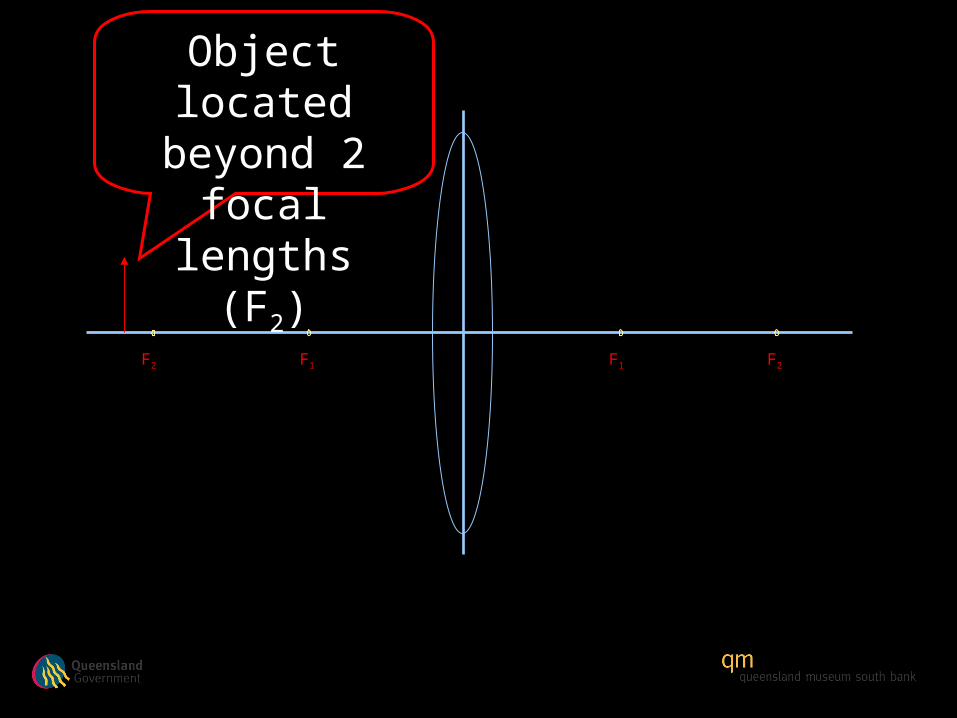
This distance from the centre of the lens to the
focus point, will be given to you as a point on a
diagram or a measurement such as 3cm.
F
Focal length
Focus
F
Focal length
Focus
F
Focal length
Focus
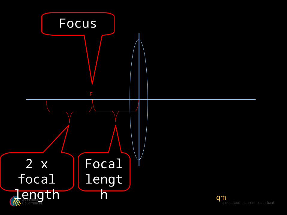
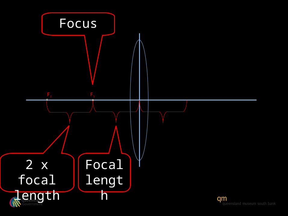
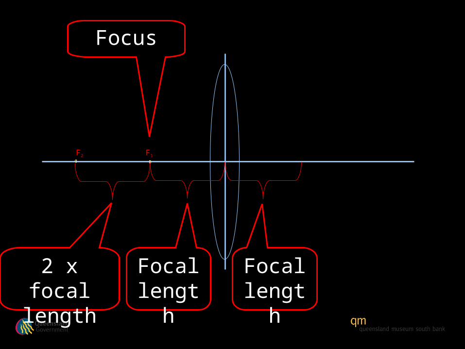
2 x focal length
F
Focal length
Focus

2 x focal length
F
Focal length
Focus

2 x focal length
FF2
Focal length
Focus

2 x focal length
F1F2
Focal length
Focus
Focal length
2 x focal length
F1F2
Focus
Focal length
2 x focal length
F1F2
Focal length
Focus

Focal length
2 x focal length
F1F2
Focal length
Focus

Focal length
2 x focal length
F1F2
Focal length
Focus Focus
Focal length
2 x focal length
F1F2 F1
Focal length
Focus Focus

Focal length
2 x focal length
F1F2 F1
Focal length
Focus Focus
Focal length
2 x focal length
F1F2 F1
Focal length
2 x focal length
Focus Focus

Focal length
2 x focal length
F1F2 F1
Focal length
2 x focal length
Focus Focus

Focal length
2 x focal length
F1F2 F1 F2
Focal length
2 x focal length
Focus Focus
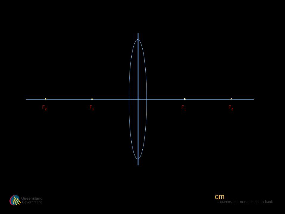
F1 F1F2 F2
F1 F1F2 F2
F1 F1F2 F2
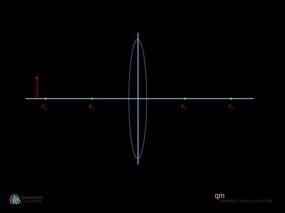
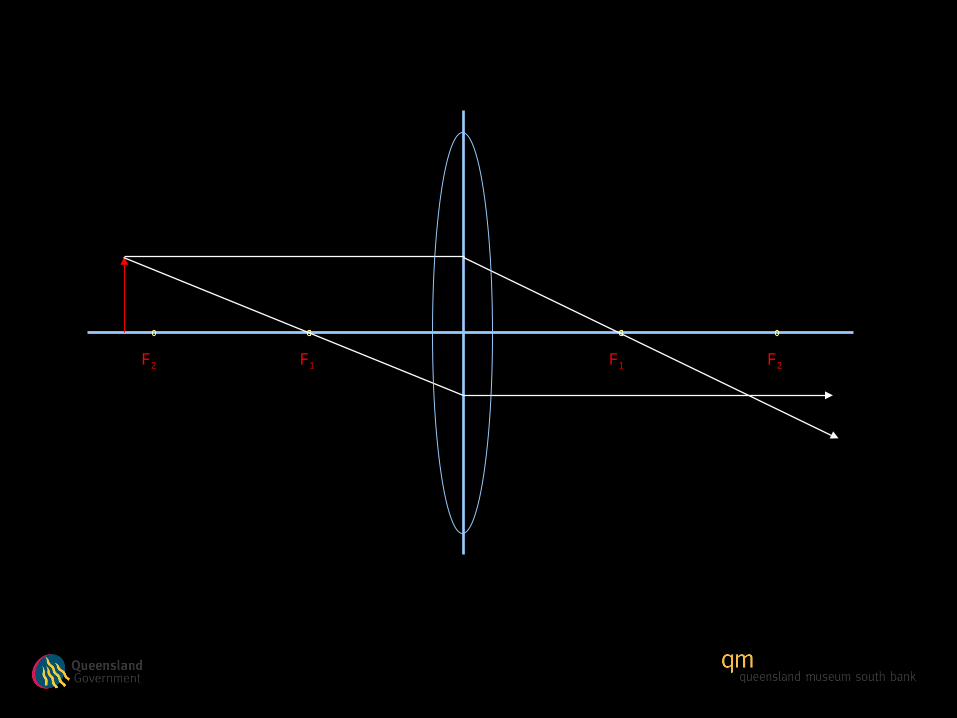
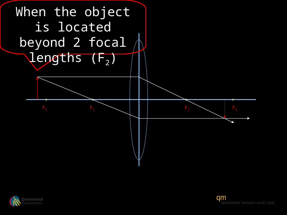
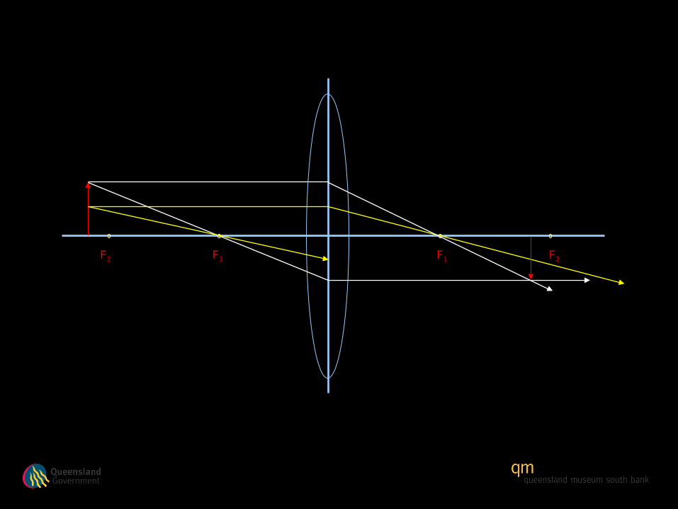
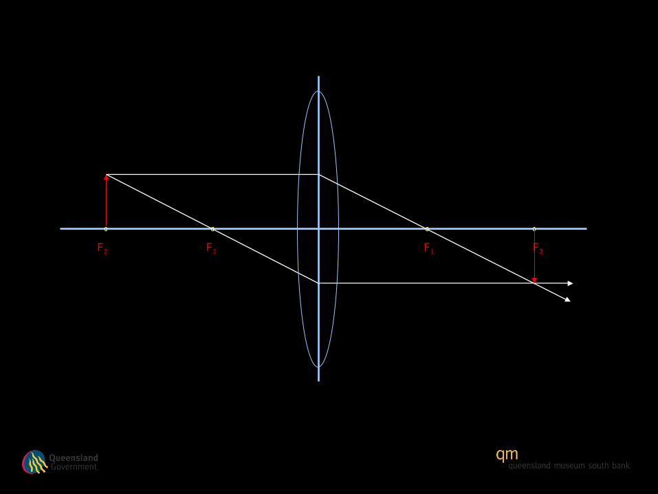
Object located beyond 2 focal
lengths (F2)
F1F1F2 F2
F1 F1F2 F2
F1 F1F2 F2
F1 F1F2 F2
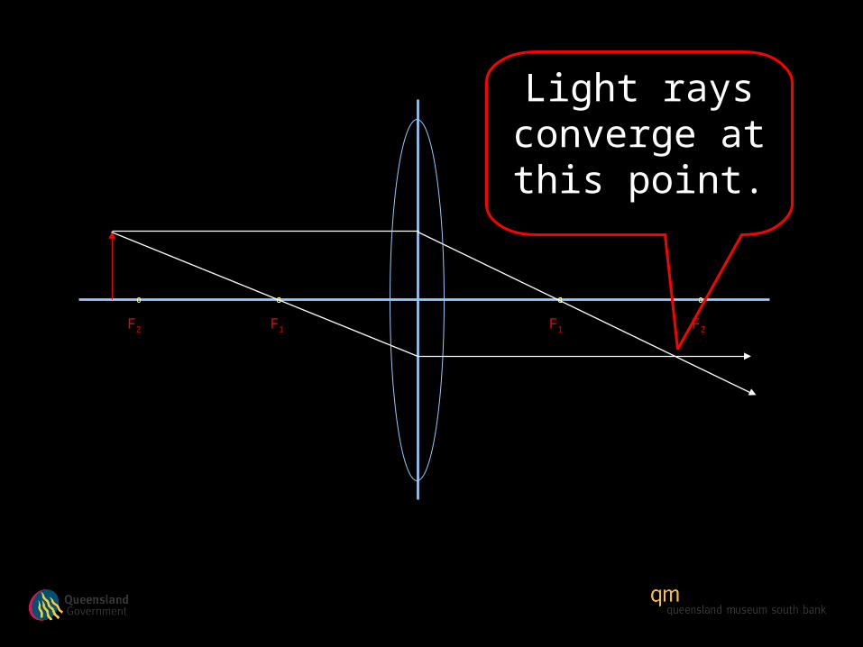
F1 F1F2 F2
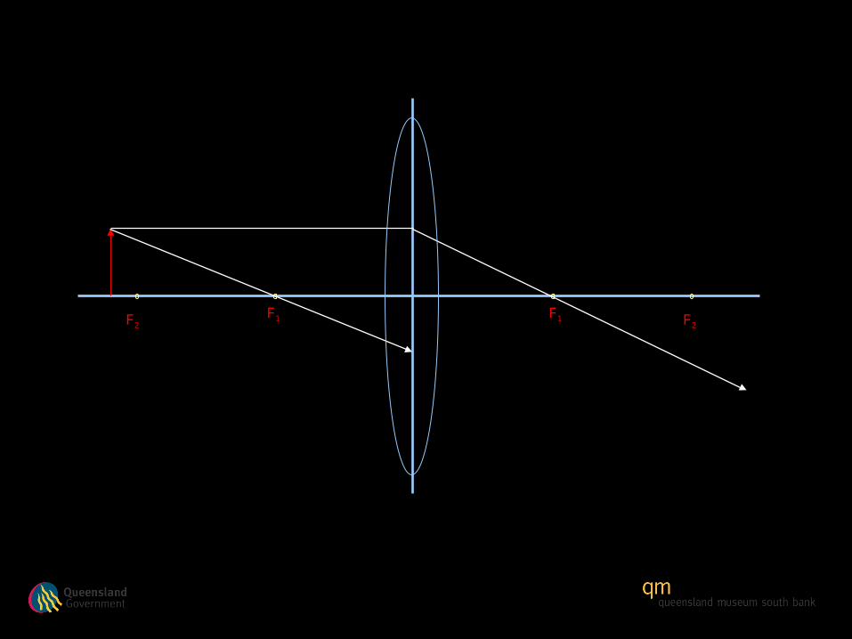
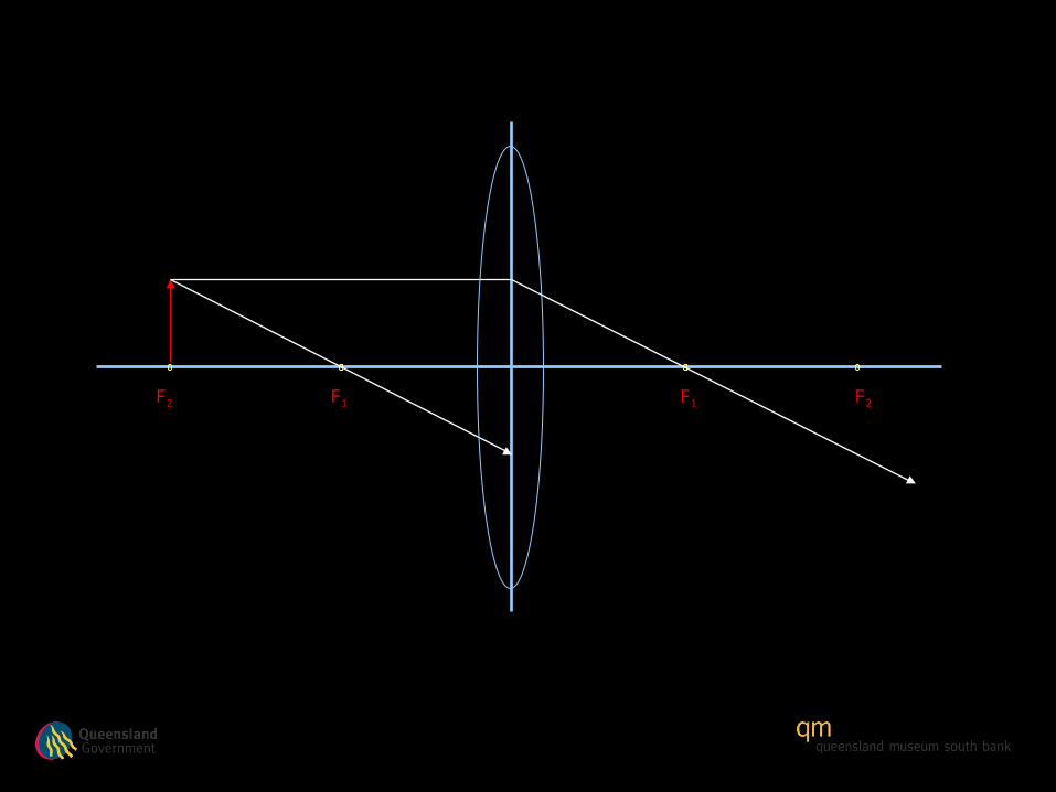
Light rays converge at this point.
F1 F1F2 F2
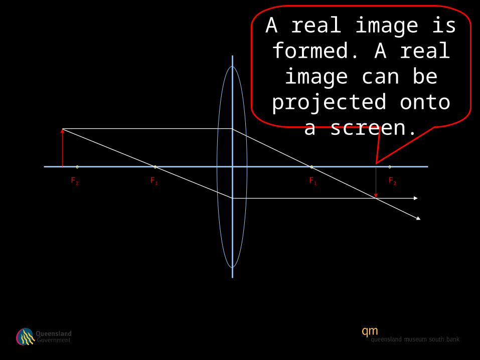
A real image is formed. A real image
can be projected onto a screen.
F1 F1F2 F2
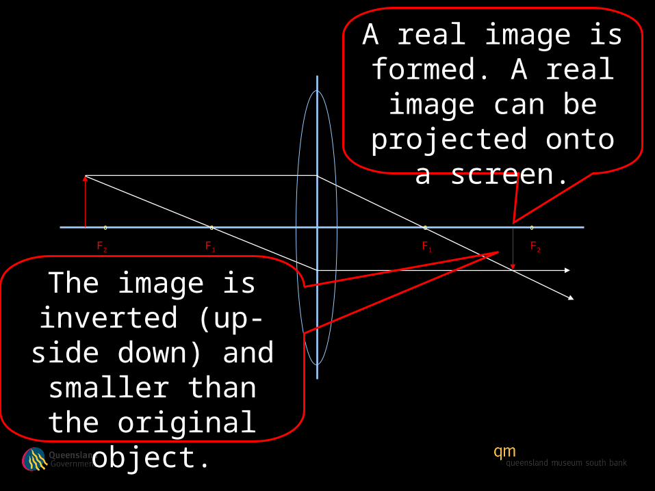
A real image is formed. A real image
can be projected onto a screen.
The image is inverted (up-side down) and
smaller than the original object.
F1 F1F2 F2
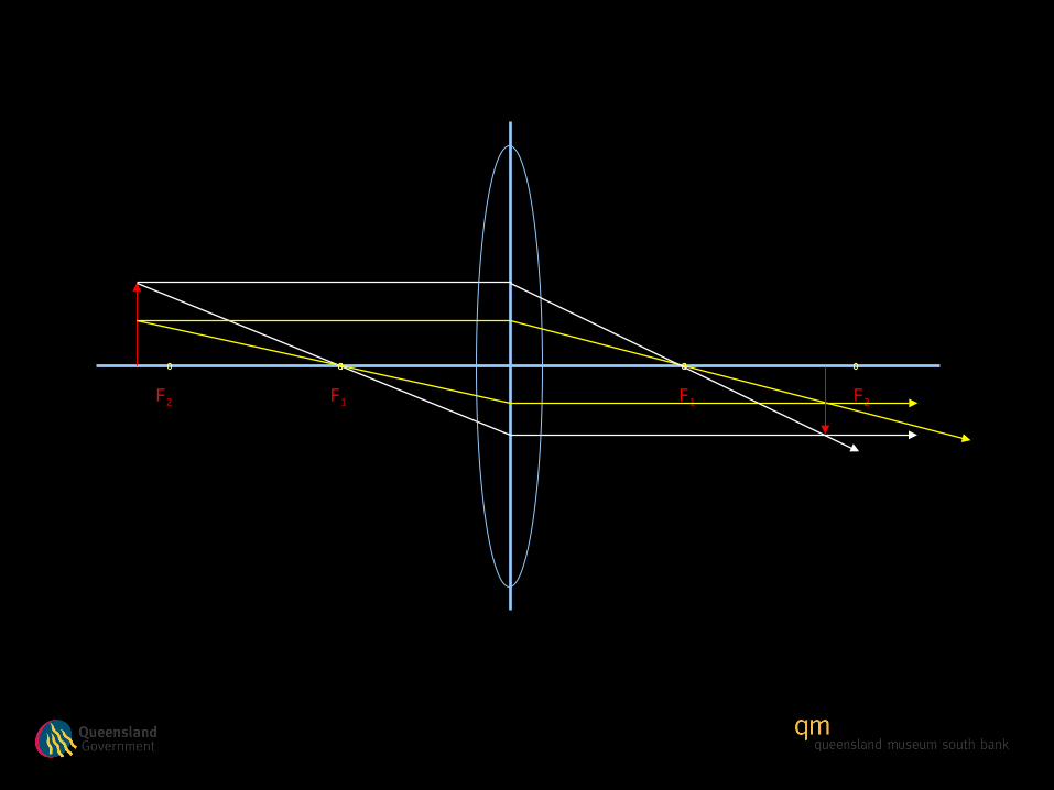
When the object is located beyond 2 focal
lengths (F2)

F1 F1F2 F2
When the object is located beyond 2 focal
lengths (F2)
The image created is real, inverted and smaller than the original object.

F1 F1F2 F2
When the object is located beyond 2 focal
lengths (F2)
The image created is real, inverted and smaller than the original object.
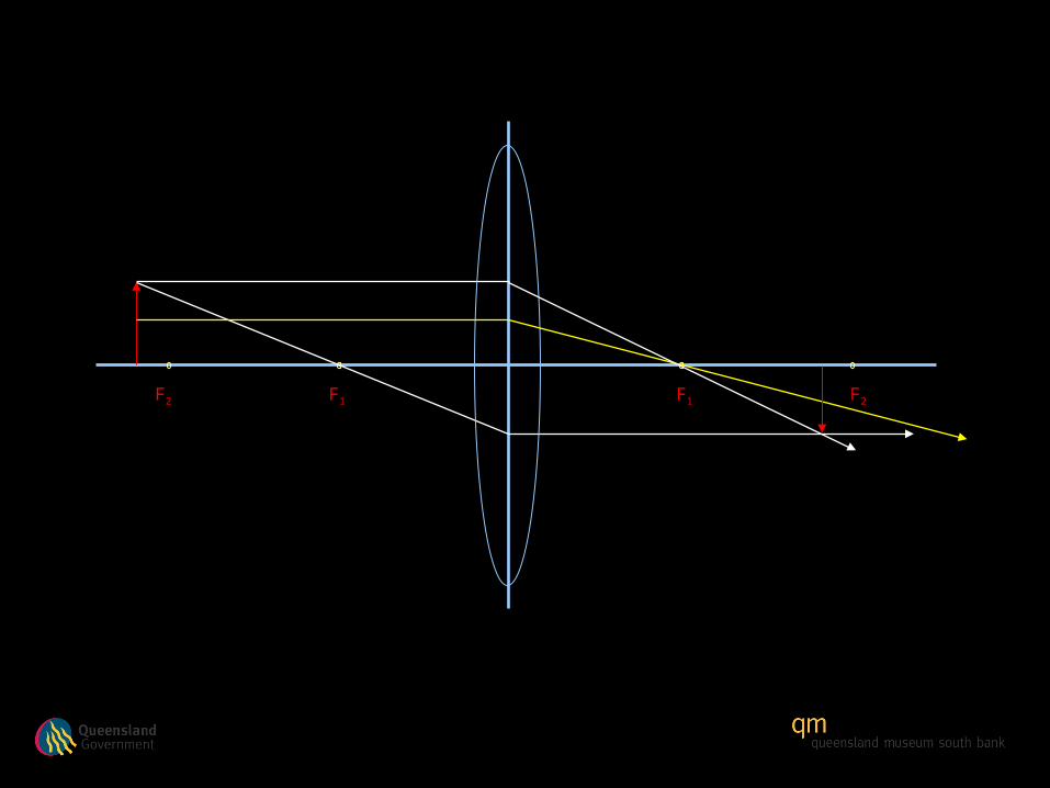
The rays converge between 1 and 2
focal lengths
F1 F1F2 F2
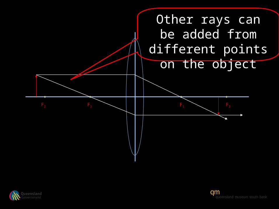
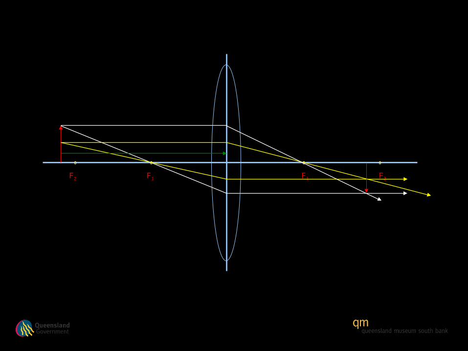
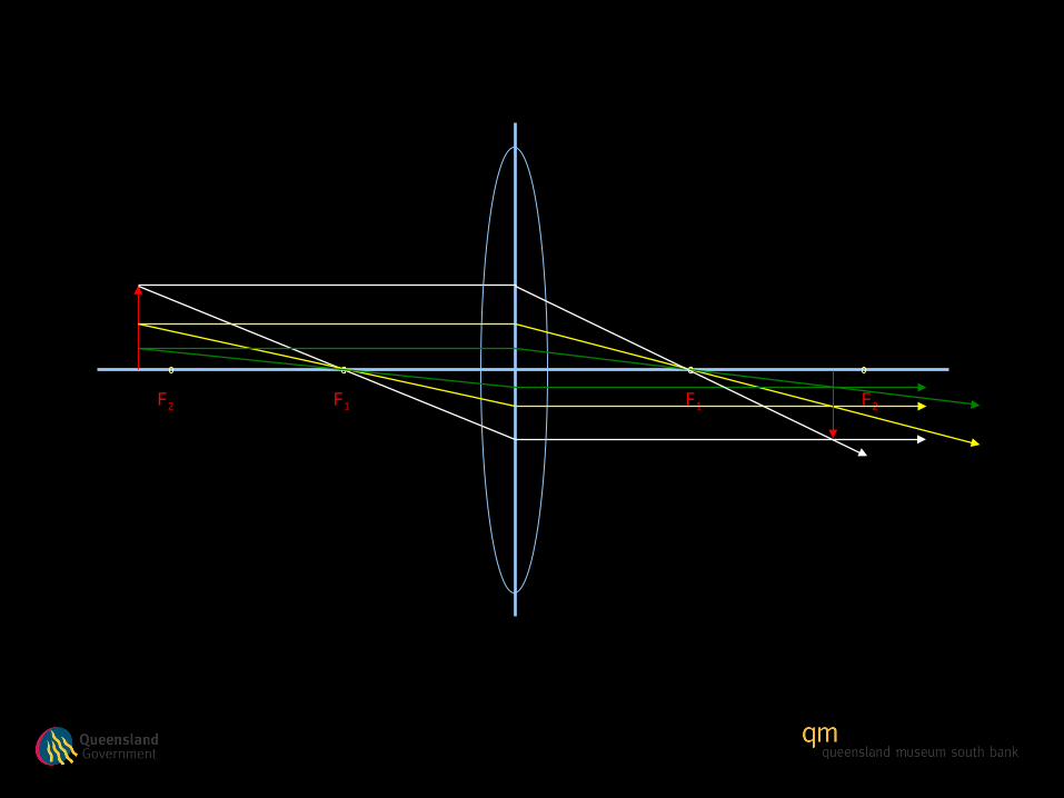
Other rays can be added from different points on the object
F1 F1F2 F2
F1 F1F2 F2
F1 F1F2 F2
F1 F1F2 F2
F1 F1F2 F2

F1 F1F2 F2
F1 F1F2 F2
F1 F1F2 F2
F1 F1F2 F2
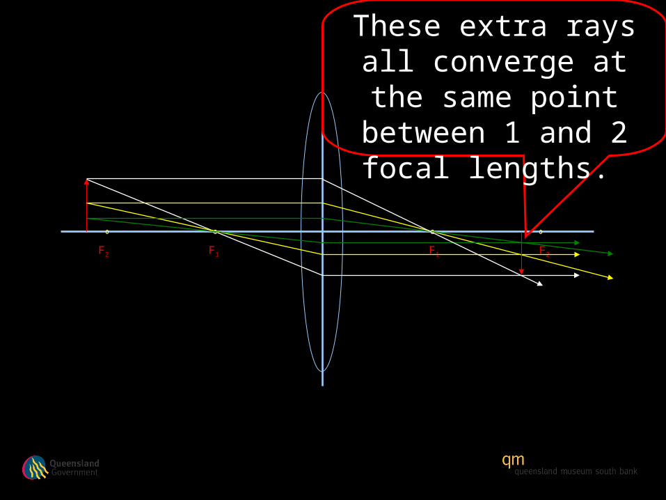
These extra rays all converge at the same point between 1 and 2
focal lengths.
F1 F1F2 F2
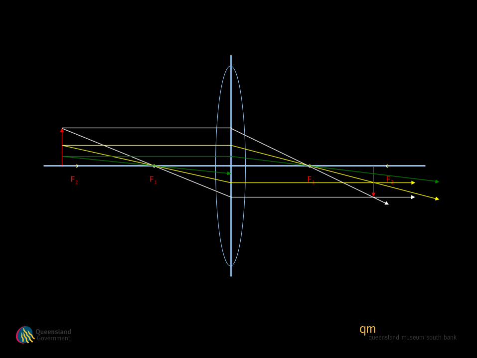
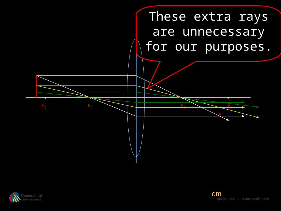
These extra rays are unnecessary for our
purposes.
F1 F1F2 F2
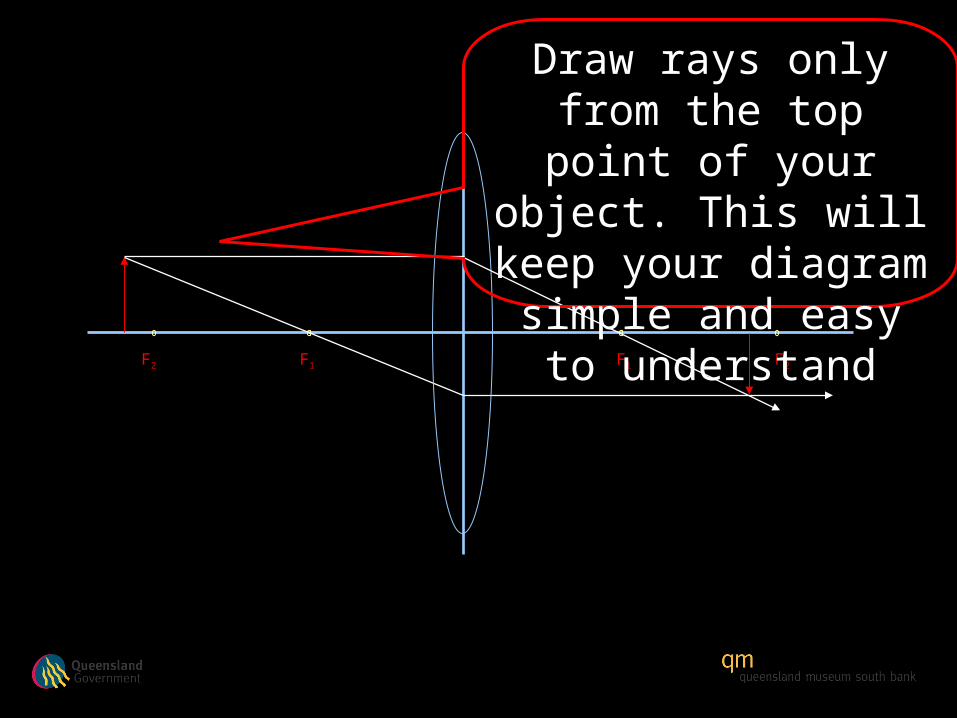
Draw rays only from the top point of your object.
This will keep your diagram simple and easy to understand
F1 F1F2 F2
F1 F1F2 F2
F1 F1F2 F2
F1 F1F2 F2

F1 F1F2 F2
F1 F1F2 F2