metal-free flat lens using negative refraction by...
TRANSCRIPT

Metal-Free Flat Lens Using Negative Refraction by Nonlinear Four-Wave Mixing
Jianjun Cao,1 Yuanlin Zheng,1 Yaming Feng,1 Xianfeng Chen,1,3 and Wenjie Wan1,2,3,*1The State Key Laboratory of Advanced Optical Communication Systems and Networks,
Department of Physics and Astronomy, Shanghai Jiao Tong University, Shanghai 200240, China2University of Michigan-Shanghai Jiao Tong University Joint Institute, Shanghai Jiao Tong University, Shanghai 200240, China
3Key Laboratory for Laser Plasmas (Ministry of Education), Shanghai Jiao Tong University, Shanghai 200240, China(Received 20 May 2014; revised manuscript received 12 September 2014; published 17 November 2014)
A perfect lens with unlimited resolution has always posed a challenge to both theoretical andexperimental physicists. Recent developments in optical metamaterials promise an attractive approachtowards perfect lenses using negative refraction to overcome the diffraction limit, improving resolution.However, those artificially engineered metamaterials are usually accompanied by high losses from metalsand are extremely difficult to fabricate. An alternative proposal using negative refraction by four-wavemixing has attracted much interest recently, though most existing experiments still require metals and noneof them have been implemented for an optical lens. Here, we experimentally demonstrate a metal-free flatlens for the first time using negative refraction by degenerate four-wave mixing with a thin glass slide.We realize an optical lensing effect utilizing a nonlinear refraction law, which may have potentialapplications in microscopy.
DOI: 10.1103/PhysRevLett.113.217401 PACS numbers: 78.66.Jg, 42.30.-d, 42.65.-k, 78.20.Ci
Flat lenses using negative refraction create a new avenuefor novel optical imaging applications, attracting intenseinterest from the optics, microwave, and even acousticcommunities [1–7]. Unlike traditional optical lenses, a flatlens which can bend incoming waves at negative anglesopposed to those within the normal refraction regime [1–3]can form an image much more sharply thanks to its abilityto negatively refract waves at all angles including evan-escent ones, making it a “perfect lens” to overcome thediffraction limit [2,6]. Such lenses have been realized inmany formats ranging from optics and microwave toacoustic, including photonic crystals [7], metal thin films[6], metamaterials [5,8–11], etc. However, most of themsuffer from high losses in association with metallic materi-als, which are the key elements bringing in negativepermittivity and artificial permeability. Second, fabricationsof such nano- or microstructures raise additional obstaclesfor their practical applications. In nonlinear optics, alter-native approaches to achieve negative refraction have beenproposed, including phase conjugation, time reversal, andfour-wave mixing (4WM) [3,12,13]. In contrast to thoseartificially engineered methods, i.e., metamaterials andphotonic crystals, which create spatial dispersion fornegative refraction using the linear composition of differ-ent materials, nonlinear optics explores nonlinear wavemixings with angle matching schemes to fulfill therequirements for negative refraction. Principally, only athin flat nonlinear slab is required. Up to now, suchnegative refractions using wave mixing have been realizedin some thin films with high nonlinearity such as metaland graphite thin films [14–16]. However, in these experi-ments, due to their low nonlinear conversion efficiencies or
their materials’ optical transparency, none of them havebeen implemented for imaging purposes.In this Letter, we experimentally demonstrate a metal-
free flat lens using negative refraction by degeneratefour-wave mixing with a simple thin glass slide. Withinglass slides containing third-order nonlinearity, a multi-color imaging scheme is realized at the millimeter scaleby converting the original infrared beams into negativerefracted visible ones through nonlinear wave mixings.During degenerate four-wave mixing processes, the phasematching conditions enable the negative refraction of4WM beams as opposed to probe beams at some specialangles. These negatively refracted 4WM beams can focusand form images while slight phase mismatches due todispersion effects or slabs’ thicknesses can blur images.In order to enhance the resolution of images, we studyboth collinear and noncollinear configurations aiming toincrease numerical apertures. This new imaging techniquemay offer a new platform for novel microscopy applica-tions in the near future.In a degenerate 4WM scheme, an intense pump beam
at frequency ω1 and a probe beam at frequency ω2 areincident onto a slab with third-order nonlinear suscep-tibility χð3Þ, generating a 4WM wave at frequency ω3 ¼2ω1 − ω2. Their corresponding phases should satisfy thephase matching condition k3 ¼ 2k1 − k2 to ensure effi-cient wavelength conversion. With a thin slab material,its thickness can also affect 4WM processes, allowing4WM with slightly mismatched phases [17]. Moreover, ifthe slab’s thickness is shorter than the wavelength, onlypartial phase matching is required in nonlinear surfaceplasmon excitations [14,18,19] or nonlinear dark-fieldmicroscopes [20]. In our experiment, the pump beam at
PRL 113, 217401 (2014) P HY S I CA L R EV I EW LE T T ER Sweek ending
21 NOVEMBER 2014
0031-9007=14=113(21)=217401(5) 217401-1 © 2014 American Physical Society
ω1 is incident on a thin glass slide normally and the probebeam at ω2 (signal beam carrying the original image)is incident at the angle of θ2, as shown in Fig. 1(a).The angle of the generated 4WM wave is denoted as θ3,measured with respect to the surface normal in thecounterclockwise direction, which is negatively opposedto the normal refraction condition through a thin glass.The phase mismatch of the 4WM process reads
Δk ¼ 2k1 − k2 − k3; ð1Þ
where ki ¼ 2πni=λi (i ¼ 1; 2; 3) are the wave vectors ofthe pump, the probe, and the 4WM beam, respectively.The ni are the corresponding refractive indices of themedium. To generate an efficient 4WM wave, the phasematching condition should be satisfied; i.e., Δk ¼ 0,which leads to
2k1 ¼ k2 cos θm2 þ k3 cos θm3 ; ð2Þ
k2 sin θm2 ¼ −k3 sin θm3 ; ð3Þ
where θm2 and θm3 are the angles in the medium.These two angles are related to the angles in air bySnell’s law:
sin θ2 ¼ n2 sin θm2 ; ð4Þ
sin θ3 ¼ n3 sin θm3 : ð5Þ
Equation (3) indicates that the 4WM wave is refractednegatively with respect to the incident probe beam.Inserting Eqs. (4) and (5) into Eq. (3), a Snell-like nonlinearrefraction law is obtained [14]:
sin θ2sin θ3
¼ − λ2λ3
: ð6Þ
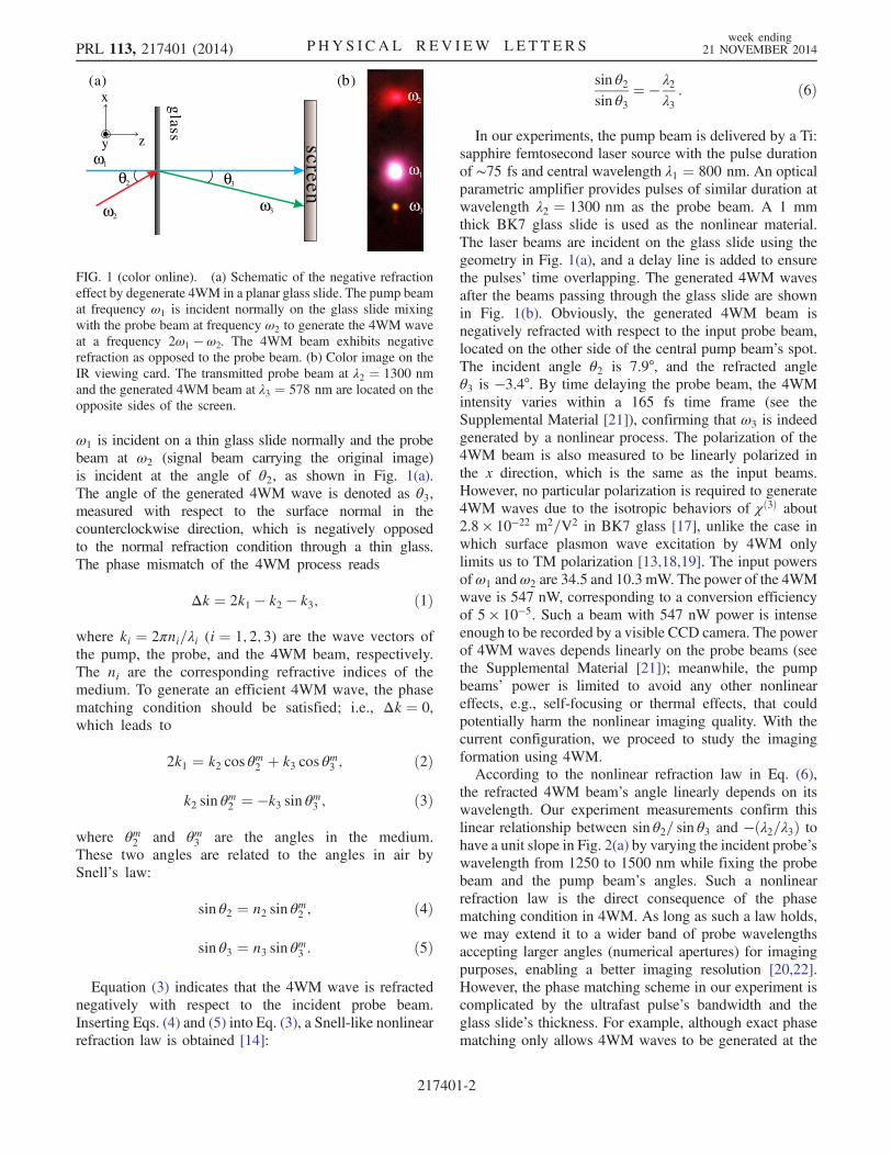
In our experiments, the pump beam is delivered by a Ti:sapphire femtosecond laser source with the pulse durationof ∼75 fs and central wavelength λ1 ¼ 800 nm. An opticalparametric amplifier provides pulses of similar duration atwavelength λ2 ¼ 1300 nm as the probe beam. A 1 mmthick BK7 glass slide is used as the nonlinear material.The laser beams are incident on the glass slide using thegeometry in Fig. 1(a), and a delay line is added to ensurethe pulses’ time overlapping. The generated 4WM wavesafter the beams passing through the glass slide are shownin Fig. 1(b). Obviously, the generated 4WM beam isnegatively refracted with respect to the input probe beam,located on the other side of the central pump beam’s spot.The incident angle θ2 is 7.9°, and the refracted angleθ3 is −3.4°. By time delaying the probe beam, the 4WMintensity varies within a 165 fs time frame (see theSupplemental Material [21]), confirming that ω3 is indeedgenerated by a nonlinear process. The polarization of the4WM beam is also measured to be linearly polarized inthe x direction, which is the same as the input beams.However, no particular polarization is required to generate4WM waves due to the isotropic behaviors of χð3Þ about2.8 × 10−22 m2=V2 in BK7 glass [17], unlike the case inwhich surface plasmon wave excitation by 4WM onlylimits us to TM polarization [13,18,19]. The input powersofω1 andω2 are 34.5 and 10.3 mW. The power of the 4WMwave is 547 nW, corresponding to a conversion efficiencyof 5 × 10⁻⁵. Such a beam with 547 nW power is intenseenough to be recorded by a visible CCD camera. The powerof 4WM waves depends linearly on the probe beams (seethe Supplemental Material [21]); meanwhile, the pumpbeams’ power is limited to avoid any other nonlineareffects, e.g., self-focusing or thermal effects, that couldpotentially harm the nonlinear imaging quality. With thecurrent configuration, we proceed to study the imagingformation using 4WM.According to the nonlinear refraction law in Eq. (6),
the refracted 4WM beam’s angle linearly depends on itswavelength. Our experiment measurements confirm thislinear relationship between sin θ2= sin θ3 and −ðλ2=λ3Þ tohave a unit slope in Fig. 2(a) by varying the incident probe’swavelength from 1250 to 1500 nm while fixing the probebeam and the pump beam’s angles. Such a nonlinearrefraction law is the direct consequence of the phasematching condition in 4WM. As long as such a law holds,we may extend it to a wider band of probe wavelengthsaccepting larger angles (numerical apertures) for imagingpurposes, enabling a better imaging resolution [20,22].However, the phase matching scheme in our experiment iscomplicated by the ultrafast pulse’s bandwidth and theglass slide’s thickness. For example, although exact phasematching only allows 4WM waves to be generated at the
θ θ
z
x
yω
ω ω
neer
cs
(a)
ssal
g
32
1
23
( )bω2
ω1
ω3
FIG. 1 (color online). (a) Schematic of the negative refractioneffect by degenerate 4WM in a planar glass slide. The pump beamat frequency ω1 is incident normally on the glass slide mixingwith the probe beam at frequency ω2 to generate the 4WM waveat a frequency 2ω1 − ω2. The 4WM beam exhibits negativerefraction as opposed to the probe beam. (b) Color image on theIR viewing card. The transmitted probe beam at λ2 ¼ 1300 nmand the generated 4WM beam at λ3 ¼ 578 nm are located on theopposite sides of the screen.
PRL 113, 217401 (2014) P HY S I CA L R EV I EW LE T T ER Sweek ending
21 NOVEMBER 2014
217401-2

exact angle, in real experiments, the ultrafast pulses have afinite linewidth ∼50 nm for the pump and ∼100 nm for theprobe, allowing 4WMs to occur in a small angle spreadingnearby. In Fig. 2(b), the 4WM intensity reaches its peak atθ2 ¼ 7.6° close to the calculated value 7.2° by Eqs. (2) and(3), while the width of the peak spreads about Δθ2 ≈ 1.0°.Since the nonlinear refraction law in Eq. (6) depicts thelinear dependence of wavelength λ to sin θ, this anglespreading is roughly close to ∼0.91° spreading, calculatedaccordingly with the input beams’ linewidth. However, forimaging applications, such small angle spreading can causeblurry images similar to chromatic aberrations due to thedispersion of a linear lens.To experimentally realize a flat lens, we consider the
phase matching condition in three-dimensional wave vectorspace, as shown in Fig. 3(a). The arrow ends of the incidentwave vector k2 that fulfill the phase matching condition in3D compose a ring in the x-y plane. For the incident wavesnear the phase matching ring, their 4WM beams [greenbeam in Fig. 3(a)] can focus on the image side according tothe nonlinear refraction law. However, for a particularincidence, e.g., k2 in Fig. 3(a), the phase matching ringsegment is not isotropic along the x-z and y-z planes; itallows a better phase matching along the y-z plane ratherthan the x-z plane in Fig. 3(b), enabling a better focus frommultiple angled 4WM waves on the y-z plane. In contrast,on the x-z plane, only one exact phase matching angle isaccepted to produce 4WMwaves, giving a weak focus withpoor image resolution.First, we experimentally realize optical imaging in a
noncollinear configuration as shown in Fig. 1(a), whichexplores the small angle cone spreading for 4WM nearthe phase matching ring mentioned above (see theSupplemental Material [21]). With such a configuration,the probe beam with a wavelength of 1300 nm is incidenton the glass slice at the angle θ2 ¼ 7.8° in the x-z planewhile the pump beammaintains normal incidence. AUSAFresolution card is placed in the path of the probe beam,4.3 cm away from the glass slide. 4WM waves negativelyrefract and form the image on the other side of the glass
slide. After filtering out the probe and pump beams withoptical filters, we can obtain the sharpest image with a CCDcamera near the focus point at the distance of around 9.0 cmaway from the glass slide. By doing this, we achieve a flatlens by probing objects with one wavelength while formingimages with others. Figures 3(c), 3(f), and 3(i) are inputimages of the resolution card, and Figs. 3(d), 3(g), and 3(j)are the corresponding images formed by 4WMwaves. As acomparison, the image of horizontal lines is much clearerthan those of vertical ones; this is because the small anglespreading caused by the object tends to have better phase
(a)
6 8 10
0.0
0.5
1.0
-2.8 -2.4 -2.0θ2
Ide
zila
mro
N3
-λ λ/2 3
sin
sin
/θ 2
θ 3(b)-2.0
-2.8
-2.4
FIG. 2 (color online). (a) Nonlinear refraction law. The relation-ship between sin θ2= sin θ3 and −ðλ2=λ3Þ is plotted with theslope of 1.01 for the linear fitting. (b) The intensity of the 4WMwave as a function of the excitation angle θ2. The dots aremeasured 4WM intensities for the probe beam at wavelengthλ2 ¼ 1300 nm. The solid curve is a Gaussian fitting.
FIG. 3 (color online). Imaging a resolution card by the non-linear negative refraction effect in the noncollinear configuration.(a) The phase matching condition for the degenerate 4WMprocess. Phase matching requires that 2k1 − k2 − k3 ¼ 0. Thedashed circular line indicates the end points of wave vector k2 thatfulfill the phase matching condition. The solid blue disk repre-sents the Fourier plane image of the resolution card. (b) The phasematching triangles in the y-z plane and the x-z plane. (c),(f),(i) Input images of the resolution card. (d),(e),(g),(h),(j),(k) Mea-sured images formed by the 4WM wave. The thickness of theglass slide is 1 mm for (d), (g), and (j) and 0.17 mm for (e), (h),and (k). The scale bar is 400 μm.
PRL 113, 217401 (2014) P HY S I CA L R EV I EW LE T T ER Sweek ending
21 NOVEMBER 2014
217401-3

matching in the y-z plane, thanks to the phase matchingring along the y-z plane in Fig. 3(a), while in the x-z plane,such 4WM is less pronounced due to limited angles thatallow for phase matching (the ring is a dot in the x-z plane,rather than a line in the y-z plane). Hence, 4WMs can bebetter generated and focused along the y-z plane, giving afiner resolution.To investigate this effect further, we replace the glass
slide with a thinner one of 0.17 mm thickness. Clearly,color images from Figs. 3(e), 3(h), and 3(k) show dis-persive colors ranging from red to green. Also, we performspectroscopic measurements along the horizontal axiswith a thin vertical slit in front of the fiber cable of aspectrometer (see the Supplemental Material [21]) toconfirm the angle spreading of the spectrum to be around0.6°, almost twice that with the 1 mm thick glass slide.Here, the thickness of the thin glass slide provides anadditional phase mismatching factor Δk ¼ 2π=d (d is thethickness) that allows 2k1 − k2 − k3 − Δk ¼ 0; hence, athinner lens leads to a wider phase matching angle in thex-z plane, as indicated in Fig. 3(b), similarly to the processin a surface plasmon excitation on a metal thin film [18,19].Such phase mismatching leads to the extra angle spreadingcompared to the thick glass case in Figs. 3(d), 3(g), and 3(j),resulting in the enlarged field of view in the horizontalaxis. Meanwhile, such a wider phase matching angle alsoenables multicolor 4WM generation, giving rise to thechromatic aberration illustrated in Fig. 3(b). Hence, imagefocusing in the x-z plane is complicated by this phasemismatching, leaving a poor resolution. It is also worthmentioning that (1) the image size is the same as the object(see Fig. 3), as these are one-to-one correspondences withmirror symmetry, with no magnification, and (2) the imagedistance Q is related to the object distance P by Q=P ¼−ðtan θ2= tan θ3Þ (the segment in the x-y plane is the same).In order to obtain a better resolution in the transverse
plane, we construct a collinear configuration to access thefull phase matching ring, where the pump and probe beamscollinearly propagate, as shown in Fig. 4(a). The pumpbeam at λ1 ¼ 800 nm, reflected by a dichroic mirror(900 nm long pass), is incident on the glass slide normally.The probe beam at λ2 ¼ 1350 nmmodulated by a “grating”is transformed and forms an “object” (as labeled in Fig. 4)in the front of the glass slide by a 4f system using twolenses with focal lengths of 4.5 and 6 cm, respectively, inorder to avoid the pump beam. The image formed by the4WM wave at λ3 ¼ 568 nm is recorded by a home-builtmicroscope (see the Supplemental Material [21]). Unlikethe noncollinear configuration, both the vertical and hori-zontal lines are clear in the current configuration by takingadvantage of the phase matching around the full ringgeometry in 3D vector space (Fig. 3). In such a way, wecan obtain images for both the horizontal and verticaldirections without the dispersion distortion as in the non-collinear configuration. However, these images seem to
have finer fringes [Figs. 4(e) and 4(i)] compared to theoriginal object in Figs. 4(b) and 4(f); this is because 4WMonly occurs around the phase matching ring while the probebeam with normal incidence cannot efficiently generate4WM due to phase mismatching. Here, the object is formedby imaging the grating, which strongly diffracts the probebeam at 0, �1 orders. The �1 order diffractions are closerto the phase matching angles encouraging 4WM, while thisis not the case for the zero-order one. Hence, 4WM images[Figs. 4(e) and 4(i)] are closer to those images of the gratingby blocking zero-order diffraction [Figs. 4(d) and 4(h)] asopposed to those with it [Figs. 4(c) and 4(g)]; see theSupplemental Material [21]. The resolution of the image isdetermined by the input’s numerical aperture, the phasematching cone in our case, which can be estimated as0.61λ2= sin θ2 ¼ 6 μm, according to Abbe’s theory [23].Since we detect images with a shorter wavelength, ideally,we could have a better resolution. Moreover, if combinedwith nonlinear numerical reconstruction methods inRefs. [24,25], the resolution can be improved further withan enlarged numerical aperture.At last, we would like to comment on the direct implied
applications with our flat lens. (1) Our flat lens can beapplied in infrared (IR) microscopy. For those fluorescencedyes or biological tissues that emit IR light, our currentconfiguration can convert them into visible light for betterdetection with a more sensitive visible CCD camera, e.g.,
gratingL
DMobject image
z
x
y
ssal
gω3
ω2
ω1
1 L2
(a)
(b) (c) (e)(d)
(f) (g) (h) (i)
FIG. 4 (color online). Imaging a grating (object) by nonlinearnegative refraction in a collinear configuration. (a) Experimentalsetup of the collinear configuration. L1, L2: lens; DM: dichroicmirror. (b),(f) Images of the object. (c),(g) Images of the objectwith grating orders �1 and 0. (d),(h) Images of the object withgrating orders �1 only by blocking zero order; see the Supple-mental Material [21]. (e),(i) Measured images formed by the4WM waves. The insets show images without pump beams.The scale bar is 6.5 μm.
PRL 113, 217401 (2014) P HY S I CA L R EV I EW LE T T ER Sweek ending
21 NOVEMBER 2014
217401-4
EMCCD, with a simple glass slide. However, given the lownonlinear conversion efficiency in our current experiment,flat lenses with high nonlinearity will be studied in thefuture. (2) Compared with other flat lenses by a metal thinfilm [6] or photonic crystal [7,26], we can achieve a muchlarger image area up to the millimeter scale determinedonly by pump beam size. (3) Superresolution imaging isalso possible by exploring a larger angle cone of the phasematching condition to accept the evanescent waves in orderto break the diffraction limit; however, proper imagingreconstruction may be required; similar proposals havebeen proposed by using the plasmonic effect in metallicnanostructures [22,27].
This work was supported by the National NaturalScience Foundation of China (Grants No. 11304201,No. 61125503 and No. 61235009), the National 1000-Plan Program (Youth), and the Shanghai Pujiang TalentProgram (Grant No. 12PJ1404700).
*To whom all correspondence should be [email protected]
[1] V. G. Veselago, Sov. Phys. Usp. 10, 509 (1968).[2] J. B. Pendry, Phys. Rev. Lett. 85, 3966 (2000).[3] J. B. Pendry, Science 322, 71 (2008).[4] A. Grbic and G. V. Eleftheriades, Phys. Rev. Lett. 92,
117403 (2004).[5] S. Zhang, L. L. Yin, and N. Fang, Phys. Rev. Lett. 102,
194301 (2009).[6] N. Fang, H. Lee, C. Sun, and X. Zhang, Science 308, 534
(2005).[7] P. V. Parimi, W. T. T. Lu, P. Vodo, and S. Sridhar, Nature
(London) 426, 404 (2003).[8] Z. W. Liu, H. Lee, Y. Xiong, C. Sun, and X. Zhang, Science
315, 1686 (2007).
[9] S. Zhang, W. J. Fan, N. C. Panoiu, K. J. Malloy, R. M.Osgood, and S. R. J. Brueck, Phys. Rev. Lett. 95, 137404(2005).
[10] H. J. Lezec, J. A. Dionne, and H. A. Atwater, Science 316,430 (2007).
[11] C. M. Soukoulis, S. Linden, and M. Wegener, Science 315,47 (2007).
[12] S. Maslovski and S. Tretyakov, J. Appl. Phys. 94, 4241(2003).
[13] A. Aubry and J. B. Pendry, J. Opt. Soc. Am. B 27, 72(2010).
[14] S. Palomba, S. Zhang, Y. Park, G. Bartal, X. Yin, andX. Zhang, Nat. Mater. 11, 34 (2011).
[15] H. Harutyunyan, R. Beams, and L. Novotny, Nat. Phys. 9,423 (2013).
[16] A. R. Katko, S. Gu, J. P. Barrett, B. I. Popa, G. Shvets, andS. A. Cummer, Phys. Rev. Lett. 105, 123905 (2010).
[17] R.W. Boyd, Nonlinear Optics (Academic, New York,2008).
[18] J. Renger, R. Quidant, N. van Hulst, S. Palomba, andL. Novotny, Phys. Rev. Lett. 103, 266802 (2009).
[19] J. Renger, R. Quidant, N. van Hulst, and L. Novotny, Phys.Rev. Lett. 104, 046803 (2010).
[20] H. Harutyunyan, S. Palomba, J. Renger, R. Quidant, andL. Novotny, Nano Lett. 10, 5076 (2010).
[21] See Supplemental Material at http://link.aps.org/supplemental/10.1103/PhysRevLett.113.217401, for detailsof pulse width, power dependence, polarization state andexperimental setups.
[22] B. Simkhovich and G. Bartal, Phys. Rev. Lett. 112, 056802(2014).
[23] E. Abbe, Arch. Mikrosc. Anat. 9, 413 (1873).[24] C. Barsi, W. J. Wan, and J. W. Fleischer, Nat. Photonics 3,
211 (2009).[25] C. Barsi and J. W. Fleischer, Nat. Photonics 7, 639 (2013).[26] N. Fabre, L. Lalouat, B. Cluzel, X. Melique, D. Lippens,
F. de Fornel, and O. Vanbesien, Phys. Rev. Lett. 101,073901 (2008).
[27] P. Y. Chen and A. Alu, Nano Lett. 11, 5514 (2011).
PRL 113, 217401 (2014) P HY S I CA L R EV I EW LE T T ER Sweek ending
21 NOVEMBER 2014
217401-5