reflectivity enhanced two-dimensional dielectric …asher/homepage/colloid_pdf/reflectivity enhanced...
TRANSCRIPT
Reflectivity enhanced two-dimensionaldielectric particle array monolayerdiffraction
Alexander TikhonovNikolay KornienkoJian-Tao ZhangLuling WangSanford A. Asher
Downloaded from SPIE Digital Library on 13 Jun 2012 to 130.49.228.25. Terms of Use: http://spiedl.org/terms
Reflectivity enhanced two-dimensional dielectricparticle array monolayer diffraction
Alexander Tikhonov, Nikolay Kornienko, Jian-Tao Zhang,Luling Wang, and Sanford A. Asher
University of Pittsburgh, Department of Chemistry, Pittsburgh, Pennsylvania [email protected]
Abstract. Very high diffraction efficiencies (>80%) were observed from two-dimensional (2-D)photonic crystals made of monolayers of ∼490 nm diameter dielectric polystyrene spheresarranged in a 2-D hexagonal lattice on top of a liquid mercury surface. These almost closepacked 2-D polystyrene particle arrays were prepared by a self-assembly spreading methodthat utilizes solvent evaporation from the mercury surface. Two-dimensional arrays transferredonto a dielectric glass substrate placed on top of metal mirrors show diffraction efficiencies ofover 30%, which is 6- to 8-fold larger than those of the same 2-D monolayers in the absence ofmirrors. A simple single particle scattering model with refraction explains the high diffractionefficiencies in terms of reflection of the high intensity forward diffraction.© 2012 Society of Photo-Optical Instrumentation Engineers (SPIE). [DOI: 10.1117/1.JNP.6.063509]
Keywords: diffraction; photonics; reflectance; photonic crystals; sensing.
Paper 12012 received Feb. 10, 2012; revised manuscript received Apr. 5, 2012; accepted forpublication Apr. 5, 2012; published online Jun. 8, 2012.
1 Introduction
Two-dimensional (2-D) photonic crystals (PC) are of great interest owing to their potential appli-cations in areas such as chemical sensing,1–3 colloidal lithography,4 and waveguiding.5 The 2-Darray PC is a 2-D diffraction grating that diffracts light into various Bragg diffraction orders.The diffracted beams either propagate outside the 2-D array PC6,7 or propagate within the 2-Darray PC in guided modes.2,3,5,8–10
The diffraction is relatively weak for low dielectric contrast 2-D array PCs. For example, 2-Darray PCs of polystyrene particles in air back diffract 1% to 10% of the incident light, dependingon the colloidal particle diameter.11,12 The diffraction efficiency of dielectric 2-D PC generallyincreases with the magnitude of the 2-D PC dielectric constant modulation.11–13 Very large dif-fraction efficiencies can be achieved from metallic 2-D array PC and/or by stacking dielectric 2-D layers to form strongly diffracting three-dimensional (3-D) PC.1,14
Maximizing the diffraction efficiency from a dielectric 2-D array PC is important for manyapplications. Although the transmission and specular reflection properties of 2-D array PCs rela-tive to the excitation of the guided modes were previously examined (for example, Refs. 2, 3, 5,and 8–10), we are not aware of any quantitative measurements of 2-D array diffraction other thanthe zero order diffraction associated with transmission and reflection.
Here we measure the diffraction of a monolayer of polystyrene colloids that self-assembleinto a 2-D hexagonal lattice on either dielectric or planar reflective substrates. We observe effi-ciencies of back-diffraction into a single diffraction order as high as 80% on a mercury surfaceand 30% from a 2-D hexagonal monolayer of polystyrene spheres arranged on a glass slideon top of a front surface aluminum mirror. The back diffraction intensity is 6- to 8-fold smallerin the absence of the mirror. We also find that the dielectric 2-D array first order diffracted beamon the forward transmission beam side (TS) is much more intense than diffracted beam on thebackward incident beam side (IS). Placing the 2-D array PC on top of a mirror combines alldiffracted beams, giving rise to a very strong diffraction, easily visible by eye.
0091-3286/2012/$25.00 © 2012 SPIE
Journal of Nanophotonics 063509-1 Vol. 6, 2012
Downloaded from SPIE Digital Library on 13 Jun 2012 to 130.49.228.25. Terms of Use: http://spiedl.org/terms
The fact that the TS diffraction is much stronger than the IS diffraction is surprising from thepoint of view of the single sphere scattering approximation15–17 since the scattering at the for-ward TS diffraction experimental angle of ∼105 deg should give less single sphere scatteringthan in the backward IS direction. The simple modification of a single sphere scattering phe-nomenon to take into account refraction by the effective 2-D array refractive index medium canexplain our observations.
2 Experimental
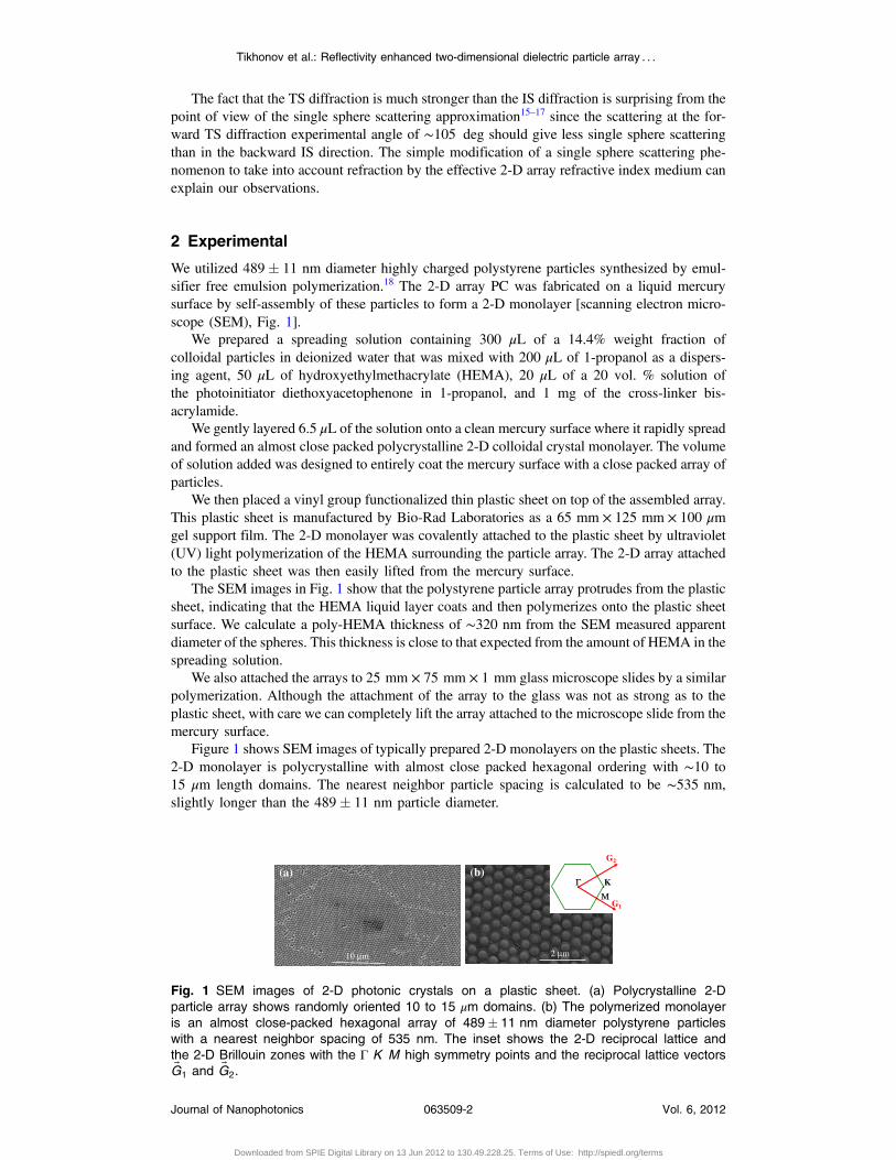
We utilized 489� 11 nm diameter highly charged polystyrene particles synthesized by emul-sifier free emulsion polymerization.18 The 2-D array PC was fabricated on a liquid mercurysurface by self-assembly of these particles to form a 2-D monolayer [scanning electron micro-scope (SEM), Fig. 1].
We prepared a spreading solution containing 300 μL of a 14.4% weight fraction ofcolloidal particles in deionized water that was mixed with 200 μL of 1-propanol as a dispers-ing agent, 50 μL of hydroxyethylmethacrylate (HEMA), 20 μL of a 20 vol. % solution ofthe photoinitiator diethoxyacetophenone in 1-propanol, and 1 mg of the cross-linker bis-acrylamide.
We gently layered 6.5 μL of the solution onto a clean mercury surface where it rapidly spreadand formed an almost close packed polycrystalline 2-D colloidal crystal monolayer. The volumeof solution added was designed to entirely coat the mercury surface with a close packed array ofparticles.
We then placed a vinyl group functionalized thin plastic sheet on top of the assembled array.This plastic sheet is manufactured by Bio-Rad Laboratories as a 65 mm × 125 mm × 100 μmgel support film. The 2-D monolayer was covalently attached to the plastic sheet by ultraviolet(UV) light polymerization of the HEMA surrounding the particle array. The 2-D array attachedto the plastic sheet was then easily lifted from the mercury surface.
The SEM images in Fig. 1 show that the polystyrene particle array protrudes from the plasticsheet, indicating that the HEMA liquid layer coats and then polymerizes onto the plastic sheetsurface. We calculate a poly-HEMA thickness of ∼320 nm from the SEM measured apparentdiameter of the spheres. This thickness is close to that expected from the amount of HEMA in thespreading solution.
We also attached the arrays to 25 mm × 75 mm × 1 mm glass microscope slides by a similarpolymerization. Although the attachment of the array to the glass was not as strong as to theplastic sheet, with care we can completely lift the array attached to the microscope slide from themercury surface.
Figure 1 shows SEM images of typically prepared 2-D monolayers on the plastic sheets. The2-D monolayer is polycrystalline with almost close packed hexagonal ordering with ∼10 to15 μm length domains. The nearest neighbor particle spacing is calculated to be ∼535 nm,slightly longer than the 489� 11 nm particle diameter.
KΓΜ
G1
G2
10 µm 2 µm
(a) (b)
Fig. 1 SEM images of 2-D photonic crystals on a plastic sheet. (a) Polycrystalline 2-Dparticle array shows randomly oriented 10 to 15 μm domains. (b) The polymerized monolayeris an almost close-packed hexagonal array of 489� 11 nm diameter polystyrene particleswith a nearest neighbor spacing of 535 nm. The inset shows the 2-D reciprocal lattice andthe 2-D Brillouin zones with the Γ K M high symmetry points and the reciprocal lattice vectors~G1 and ~G2.
Tikhonov et al.: Reflectivity enhanced two-dimensional dielectric particle array : : :
Journal of Nanophotonics 063509-2 Vol. 6, 2012
Downloaded from SPIE Digital Library on 13 Jun 2012 to 130.49.228.25. Terms of Use: http://spiedl.org/terms
3 Results and Discussion
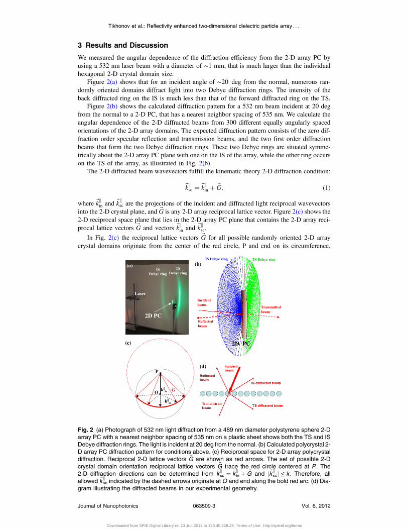
We measured the angular dependence of the diffraction efficiency from the 2-D array PC byusing a 532 nm laser beam with a diameter of ∼1 mm, that is much larger than the individualhexagonal 2-D crystal domain size.
Figure 2(a) shows that for an incident angle of ∼20 deg from the normal, numerous ran-domly oriented domains diffract light into two Debye diffraction rings. The intensity of theback diffracted ring on the IS is much less than that of the forward diffracted ring on the TS.
Figure 2(b) shows the calculated diffraction pattern for a 532 nm beam incident at 20 degfrom the normal to a 2-D PC, that has a nearest neighbor spacing of 535 nm. We calculate theangular dependence of the 2-D diffracted beams from 300 different equally angularly spacedorientations of the 2-D array domains. The expected diffraction pattern consists of the zero dif-fraction order specular reflection and transmission beams, and the two first order diffractionbeams that form the two Debye diffraction rings. These two Debye rings are situated symme-trically about the 2-D array PC plane with one on the IS of the array, while the other ring occurson the TS of the array, as illustrated in Fig. 2(b).
The 2-D diffracted beam wavevectors fulfill the kinematic theory 2-D diffraction condition:
~kksc ¼ ~kkin þ ~G; (1)
where ~kkin and ~kksc are the projections of the incident and diffracted light reciprocal wavevectorsinto the 2-D crystal plane, and ~G is any 2-D array reciprocal lattice vector. Figure 2(c) shows the2-D reciprocal space plane that lies in the 2-D array PC plane that contains the 2-D array reci-procal lattice vectors ~G and vectors ~kkin and ~kksc.
In Fig. 2(c) the reciprocal lattice vectors ~G for all possible randomly oriented 2-D arraycrystal domains originate from the center of the red circle, P and end on its circumference.
k||in
k||sc
G
(c)
O
P
Laser
2D PC
IS Debye ring
TS Debye ring
(a)
Incident beam
IS Debye ring TS Debye ring
Reflected beam
2D PC
Transmitted beam
(b)
(d)
Fig. 2 (a) Photograph of 532 nm light diffraction from a 489 nm diameter polystyrene sphere 2-Darray PC with a nearest neighbor spacing of 535 nm on a plastic sheet shows both the TS and ISDebye diffraction rings. The light is incident at 20 deg from the normal. (b) Calculated polycrystal 2-D array PC diffraction pattern for conditions above. (c) Reciprocal space for 2-D array polycrystaldiffraction. Reciprocal 2-D lattice vectors ~G are shown as red arrows. The set of possible 2-Dcrystal domain orientation reciprocal lattice vectors ~G trace the red circle centered at P. The2-D diffraction directions can be determined from ~k
ksc ¼ ~k
kin þ ~G and j ~kk
scj ≤ k . Therefore, allallowed ~k
ksc indicated by the dashed arrows originate at O and end along the bold red arc. (d) Dia-
gram illustrating the diffracted beams in our experimental geometry.
Tikhonov et al.: Reflectivity enhanced two-dimensional dielectric particle array : : :
Journal of Nanophotonics 063509-3 Vol. 6, 2012
Downloaded from SPIE Digital Library on 13 Jun 2012 to 130.49.228.25. Terms of Use: http://spiedl.org/terms
The projection of the incident light wavevector into the 2-D array plane is the light incident in-
plane wavevector ~kkin ¼ ~OP. Its length depends upon its angle of incidence. In order to satisfy
Eq. (1) the scattered vectors ~kksc must originate at point O and end on the red circle circumference.
Since the projection ~kksc cannot be larger than k ¼ j~kscj ¼ j~kinj, the allowed ~kksc must lie within theblack circle with origin O and radius k. Therefore a Debye diffraction ring will be formed by all
diffracted beams with ~kksc starting at O and ending on the bold red arc as defined by the black
dashed arrows. The resulting Debye ring diffraction pattern is formed by these scattered ~ksc. Thelight from the Debye rings illuminate two arcs along the observation plane as observed inFig. 2(a).
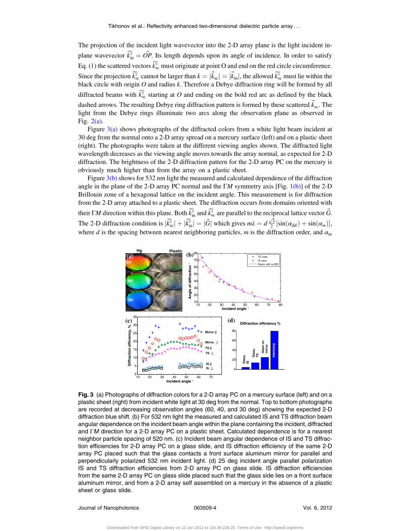
Figure 3(a) shows photographs of the diffracted colors from a white light beam incident at30 deg from the normal onto a 2-D array spread on a mercury surface (left) and on a plastic sheet(right). The photographs were taken at the different viewing angles shown. The diffracted lightwavelength decreases as the viewing angle moves towards the array normal, as expected for 2-Ddiffraction. The brightness of the 2-D diffraction pattern for the 2-D array PC on the mercury isobviously much higher than from the array on a plastic sheet.
Figure 3(b) shows for 532 nm light the measured and calculated dependence of the diffractionangle in the plane of the 2-D array PC normal and the ΓM symmetry axis [Fig. 1(b)] of the 2-DBrillouin zone of a hexagonal lattice on the incident angle. This measurement is for diffractionfrom the 2-D array attached to a plastic sheet. The diffraction occurs from domains oriented with
their ΓM direction within this plane. Both ~kkin and ~kksc are parallel to the reciprocal lattice vector ~G.
The 2-D diffraction condition is j~kkscj þ j~kkinj ¼ j ~Gj which gives mλ ¼ dffiffi
3p2½sinðαdifÞ þ sinðαinÞ�,
where d is the spacing between nearest neighboring particles, m is the diffraction order, and αin
0
20
40
60
80
10 20 30 40 50 60 700
5
10
15
20
25
30
35
10 20 30 40 50 60 70 8010
20
30
40
50
60
70
80TS case
IS casetheory with a=520
Dif
frac
tio
n e
ffic
ien
cy, %
Incident angle °
(a) (b)
(c) Diffraction efficiency %(d)
Incident angle °
An
gle
of
dif
frac
tio
n °
Hg Plastic
Gla
ss,
IS
Gla
ss,
TS
Gla
ss o
n
mir
ror
mer
cury
60°
40°
30°
Mirror ||
Mirror _|_
TS ||
TS _|_
IS _|_IS ||
Fig. 3 (a) Photographs of diffraction colors for a 2-D array PC on a mercury surface (left) and on aplastic sheet (right) from incident white light at 30 deg from the normal. Top to bottom photographsare recorded at decreasing observation angles (60, 40, and 30 deg) showing the expected 2-Ddiffraction blue shift. (b) For 532 nm light the measured and calculated IS and TS diffraction beamangular dependence on the incident beam angle within the plane containing the incident, diffractedand ΓM direction for a 2-D array PC on a plastic sheet. Calculated dependence is for a nearestneighbor particle spacing of 520 nm. (c) Incident beam angular dependence of IS and TS diffrac-tion efficiencies for 2-D array PC on a glass slide, and IS diffraction efficiency of the same 2-Darray PC placed such that the glass contacts a front surface aluminum mirror for parallel andperpendicularly polarized 532 nm incident light. (d) 25 deg incident angle parallel polarizationIS and TS diffraction efficiencies from 2-D array PC on glass slide. IS diffraction efficienciesfrom the same 2-D array PC on glass slide placed such that the glass side lies on a front surfacealuminum mirror, and from a 2-D array self assembled on a mercury in the absence of a plasticsheet or glass slide.
Tikhonov et al.: Reflectivity enhanced two-dimensional dielectric particle array : : :
Journal of Nanophotonics 063509-4 Vol. 6, 2012
Downloaded from SPIE Digital Library on 13 Jun 2012 to 130.49.228.25. Terms of Use: http://spiedl.org/terms
and αdif are the incident and diffracted angles from the normal. The measured diffraction anglesfor both the TS and IS (relative to the 2-D PC plane) diffracted light agree well with those cal-culated for d ¼ 520 nm [Fig. 3(b)].
Figure 3(c) shows the measured angular dependence of the diffraction efficiency of a 532 nmlaser beam from the 2-D array PC attached to a glass microscope slide in the case that the dif-fracted beam lies in the same plane as the incident beam and the 2-D plane normal. The intensitydiffracted into the Debye ring was estimated by measuring the intensity diffracted into a smallarea of the Debye ring and then dividing this intensity by the relative fraction compared to thetotal ring. The intensity per unit area measured from different regions of the Debye ring is rela-tively constant, varying by <20%.
For a 532 nm parallel polarized beam incident at 25 deg from the normal to the 2-D array PCon the glass slide we measured a diffraction efficiency of 4.5% for the IS and 15% for the TSDebye rings [Fig. 3(d)]. In contrast, we measured a 30% diffraction efficiency (that is larger thanthe sum of the TS and IS diffracted intensities in the absence of the mirror) from the same 2-Darray PC on the glass slide when we placed its glass side on a front surface aluminum mirror.A 2-D array PC self assembled on the mercury shows an even larger diffraction efficiencyof ∼80% at the same incidence angle.
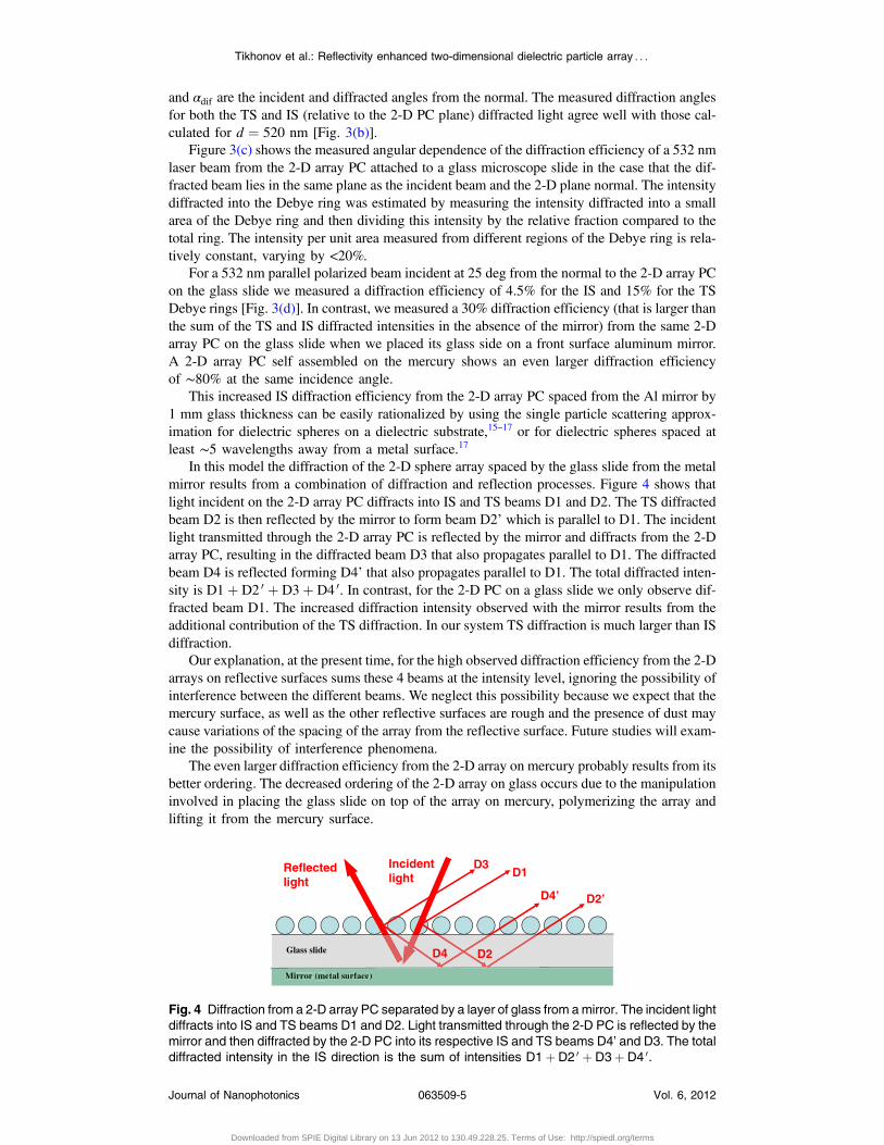
This increased IS diffraction efficiency from the 2-D array PC spaced from the Al mirror by1 mm glass thickness can be easily rationalized by using the single particle scattering approx-imation for dielectric spheres on a dielectric substrate,15–17 or for dielectric spheres spaced atleast ∼5 wavelengths away from a metal surface.17
In this model the diffraction of the 2-D sphere array spaced by the glass slide from the metalmirror results from a combination of diffraction and reflection processes. Figure 4 shows thatlight incident on the 2-D array PC diffracts into IS and TS beams D1 and D2. The TS diffractedbeam D2 is then reflected by the mirror to form beam D2’ which is parallel to D1. The incidentlight transmitted through the 2-D array PC is reflected by the mirror and diffracts from the 2-Darray PC, resulting in the diffracted beam D3 that also propagates parallel to D1. The diffractedbeam D4 is reflected forming D4’ that also propagates parallel to D1. The total diffracted inten-sity is D1þ D2 0 þ D3þ D4 0. In contrast, for the 2-D PC on a glass slide we only observe dif-fracted beam D1. The increased diffraction intensity observed with the mirror results from theadditional contribution of the TS diffraction. In our system TS diffraction is much larger than ISdiffraction.
Our explanation, at the present time, for the high observed diffraction efficiency from the 2-Darrays on reflective surfaces sums these 4 beams at the intensity level, ignoring the possibility ofinterference between the different beams. We neglect this possibility because we expect that themercury surface, as well as the other reflective surfaces are rough and the presence of dust maycause variations of the spacing of the array from the reflective surface. Future studies will exam-ine the possibility of interference phenomena.
The even larger diffraction efficiency from the 2-D array on mercury probably results from itsbetter ordering. The decreased ordering of the 2-D array on glass occurs due to the manipulationinvolved in placing the glass slide on top of the array on mercury, polymerizing the array andlifting it from the mercury surface.
Mirror (metal surface)
D3D1
D2’D4’
Incidentlight
Reflected light
D4 D2Glass slide
Mirror (metal surfaceff )
Fig. 4 Diffraction from a 2-D array PC separated by a layer of glass from amirror. The incident lightdiffracts into IS and TS beams D1 and D2. Light transmitted through the 2-D PC is reflected by themirror and then diffracted by the 2-D PC into its respective IS and TS beams D4’ and D3. The totaldiffracted intensity in the IS direction is the sum of intensities D1þ D2 0 þ D3þ D4 0.
Tikhonov et al.: Reflectivity enhanced two-dimensional dielectric particle array : : :
Journal of Nanophotonics 063509-5 Vol. 6, 2012
Downloaded from SPIE Digital Library on 13 Jun 2012 to 130.49.228.25. Terms of Use: http://spiedl.org/terms
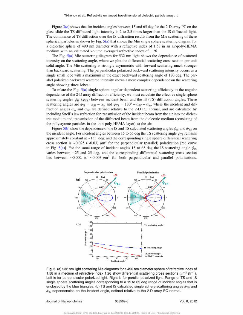
Figure 3(c) shows that for incident angles between 15 and 65 deg for the 2-D array PC on theglass slide the TS diffracted light intensity is 2 to 2.5 times larger than the IS diffracted light.The dominance of TS diffraction over the IS diffraction results from the Mie scattering of thesespherical particles as shown by Fig. 5(a) that shows the Mie single sphere scattering diagram fora dielectric sphere of 490 nm diameter with a refractive index of 1.58 in an air-poly-HEMAmedium with an estimated volume averaged refractive index of 1.26.
The Fig. 5(a) Mie scattering diagram for 532 nm light shows the dependence of scatteredintensity on the scattering angle, where we plot the differential scattering cross section per unitsolid angle. The Mie scattering is strongly asymmetric with forward scattering much strongerthan backward scattering. The perpendicular polarized backward scattering intensity occurs as asingle small lobe with a maximum in the exact backward scattering angle of 180 deg. The par-allel polarized backward scattered intensity shows a more complex dependence on the scatteringangle showing three lobes.
To relate the Fig. 5(a) single sphere angular dependent scattering efficiency to the angulardependence of the 2-D array diffraction efficiency, we must calculate the effective single spherescattering angles ϕIS (ϕTS) between incident beam and the IS (TS) diffraction angles. Thesescattering angles are ϕIS ¼ αdif − αin and ϕTS ¼ 180° − αdif − αin, where the incident and dif-fraction angles αin and αdif are defined relative to the 2-D PC normal, and are calculated byincluding Snell’s law refraction for transmission of the incident beam from the air into the dielec-tric medium and transmission of the diffracted beam from the dielectric medium (consisting ofthe polystyrene particles in the thin poly-HEMA layer) to the air.
Figure 5(b) show the dependence of the IS and TS calculated scattering angles ϕIS and ϕTS onthe incident angle. For incident angles between 15 to 65 deg the TS scattering angle ϕTS remainsapproximately constant at ∼133 deg, and the corresponding single sphere differential scatteringcross section is ∼0.025 (∼0.03) μm2 for the perpendicular (parallel) polarization [red curvein Fig. 5(a)]. For the same range of incident angles 15 to 65 deg the IS scattering angle ϕIS
varies between −25 and 25 deg, and the corresponding differential scattering cross sectionlies between ∼0.002 to ∼0.003 μm2 for both perpendicular and parallel polarizations.
0.2
0.4
30
210
60
240
90
270
120
300
150
330
0081
0.2
0.4
30
210
60
240
90
270
120
300
150
330
0081
20 30 40 50 60
-20
0
20
40
60
80
100
120
140
x20 x20Perpendicular polarization Parallel polarization
(b)
(a)
Incident angle °
Scat
tere
d an
gle
°
TS scattering angle
IS scattering angle
Diffracted angle (to 2D PC normal)
φIS
φTS φTS
φIS
Fig. 5 (a) 532 nm light scattering Mie diagrams for a 490 nm diameter sphere of refractive index of1.58 in a medium of refractive index 1.26 show differential scattering cross sections (μm2 str−1).Left is for perpendicular polarized light. Right is for parallel polarized light. Range of TS and ISsingle sphere scattering angles corresponding to a 15 to 65 deg range of incident angles that isenclosed by the blue triangles. (b) TS and IS calculated single sphere scattering angles ϕTS andϕIS dependencies on the incident angle, defined relative to the 2-D array PC normal.
Tikhonov et al.: Reflectivity enhanced two-dimensional dielectric particle array : : :
Journal of Nanophotonics 063509-6 Vol. 6, 2012
Downloaded from SPIE Digital Library on 13 Jun 2012 to 130.49.228.25. Terms of Use: http://spiedl.org/terms
The large increased single sphere scattering power in the TS direction relative to the IS directionexplains that the observed data in Fig. 3(b) results from the much stronger Mie forward scatteringefficiency.
It is essential to include Snells law refraction to explain our experimental observations.Without taking into account refraction the TS scattering angle is ∼105 deg and the IS scatteringangle varies between −20 and 20 deg. For these scattering angles, the single sphere scatter-ing in TS direction would be less then in the IS directions (Fig. 5). Snell’s law refractionaccounts for the fact that the local field incident and diffracted fields from the sphere arrayare a combination of the incident electric field and the scattered fields from all other spheres.We approximate the contribution of the other spheres by invoking an effective medium approx-imation19 and calculating the directions of the local incident and local scattered fields as if indi-vidual spheres were embedded in a homogeneous layer with an effective volume averagedrefractive index.
However the inclusion of refraction is not trivially obvious since the 2-D diffraction conditionis independent of the refractive index of the 2-D array particles and monolayer medium.20
The effect of the refractive index on refraction at the monolayer interface cancels the impactof the refractive index on the wavelength of light. For example, in the Littrow configurationwith ~kin ¼ −~ksc the 2-D Bragg diffraction relation does not depend on refractive index:mλ0 ¼ 3 1
2d sin θ, where m is the diffraction order, λ0 is the diffracted wavelength (in vacuum),
d is the 2-D particle spacing, and θ is the angle relative to the normal to the 2-D array. For a fixed2-D array spacing changing the monolayer refractive index does not change the diffractioncondition but changes the relative diffracted intensity ratio between the IS and TS dif-fracted beams.
4 Summary
We report the first measurements of the light diffraction efficiency from a dielectric 2-D array PCon dielectric and metal substrates. We prepared almost closed packed 2-D polystyrene particlearrays by solvent evaporation of self assembling monolayers on mercury surfaces. The 532 nmlight diffraction efficiency from a 2-D array PC on a glass slide in the TS direction was measuredto be 3- to 4-fold larger then in the IS direction. This difference is due to larger Mie forwardscattering intensities of single sphere scattering. The observed scattered diffraction efficiency isextraordinarily high, reaching 80% for a 2-D array PC on a mercury surface. The observed dif-fraction efficiency is only 30% for a 2-D array PC on a glass slide placed on a front surfacealuminum mirror.
These high diffraction efficiencies of monolayer arrays of polystyrene spheres enable theiruse as visually evident chemical sensing materials.21
Acknowledgments
The authors are grateful for the financial support from HDTRA (Grant No. 1-10-1-0044). Allauthors of the paper contributed significantly to the work reported in this manuscript.
References
1. X. Yu et al., “High quality factor metallodielectric hybrid plasmonic–photonic crystals,”Adv. Funct. Mater. 20(12), 1910–1916 (2010), http://dx.doi.org/10.1002/adfm.v20:12.
2. L. Shi et al., “Guided-mode resonance photonic crystal slab sensors based on beadmonolayer geometry,” Opt. Express 16(22), 17962–17971 (2008), http://dx.doi.org/10.1364/OE.16.017962.
3. J. Ge and Y. Yin, “Responsive photonic crystals,” Angew. Chem. Int. Ed. 50(7), 1492–1522(2011), http://dx.doi.org/10.1002/anie.200907091.
4. J. Zhang et al., “Colloidal self-assembly meets nanofabrication: from two-dimensionalcolloidal crystals to nanostructure arrays,” Adv. Mater. 22(38), 4249–4269 (2010),http://dx.doi.org/10.1002/adma.201000755.
Tikhonov et al.: Reflectivity enhanced two-dimensional dielectric particle array : : :
Journal of Nanophotonics 063509-7 Vol. 6, 2012
Downloaded from SPIE Digital Library on 13 Jun 2012 to 130.49.228.25. Terms of Use: http://spiedl.org/terms
5. S. Fan and J. D. Joannopoulos, “Analysis of guided resonances in photonic crystal slabs,”Phys. Rev. B 65(23), 235112 (2002), http://dx.doi.org/10.1103/PhysRevB.65.235112.
6. G. von Freymanna et al., “Diffraction properties of two-dimensional photonic crystal,”Appl. Phys. Lett. 83(4), 614–616 (2003), http://dx.doi.org/10.1063/1.1596731.
7. G. Alagappan, X. W. Sun, and M. B. Yu, “Out-of-plane diffraction of a two-dimenisonalphotonic crystal with finite dielectric modulation,” J. Opt. Soc. Am. A 25(5), 1098–1103(2008), http://dx.doi.org/10.1364/JOSAA.25.001098.
8. Y. Kurokawa, H. Miyazaki, and Y. Jimba, “Light scattering from a monolayer of periodi-cally arrayed dielectric spheres on dielectric substrates,” Phys. Rev. B 65(20), 201102(2002), http://dx.doi.org/10.1103/PhysRevB.65.201102.
9. M. Inoue, “Enhancement of local field by a two-dimensional array of dielectric spheresplaced on a substrate,” Phys. Rev. B 36(5), 2852–2862 (1987), http://dx.doi.org/10.1103/PhysRevB.36.2852.
10. K. Ohtaka et al., “Photonic band effects in a two-dimensional array of dielectric spheres inthe millimeter-wave region,” Phys. Rev. B 61(8), 5267–5279 (2000), http://dx.doi.org/10.1103/PhysRevB.61.5267.
11. K. Busch et al., “Periodic nanostructures for photonics,” Phys. Rep. 444(3–6), 101–202(2007), http://dx.doi.org/10.1016/j.physrep.2007.02.011.
12. A. Tikhonov, R. D. Coalson, and S. A. Asher, “Light diffraction from colloidal crystalswith low dielectric constant modulation: simulations using single-scattering,” Phys. Rev.B 77(23), 235404 (2008), http://dx.doi.org/10.1103/PhysRevB.77.235404.
13. A. V. Baryshev et al., “Light diffraction from opal-based photonic crystals with growth-induced disorder: experiment and theory,” Phys. Rev. B 73(20), 205118 (2006), http://dx.doi.org/10.1103/PhysRevB.73.205118.
14. S. A. Asher et al., “Diffraction in crystalline colloidal-array photonic crystals,” Phys. Rev. E69(6), 066619 (2004), http://dx.doi.org/10.1103/PhysRevE.69.066619.
15. M. A. Taubenblatt and T. K. Tran, “Calculation of light scattering from particles and struc-tures on a surface by the coupled-dipole method,” J. Opt. Soc. Am. A 10(5), 912–919 (1993),http://dx.doi.org/10.1364/JOSAA.10.000912.
16. K. B. Nahm and W. L. Wolfe, “Light scattering models for spheres on a conducting plane:comparison with experiment,” Appl. Opt. 26(15), 2995–2999 (1987), http://dx.doi.org/10.1364/AO.26.002995.
17. B. R. Johnson, “Light scattering from a spherical particle on a conducting plane: I. normalincidence,” J. Opt. Soc. Am. A 9(8), 1341–1351 (1992), http://dx.doi.org/10.1364/JOSAA.9.001341.
18. C. E. Reese and S. A. Asher, “Emulsifier-free emulsion polymerization produces highlycharged, monodisperse particles for near infrared photonic crystals” J. Coll. Interf. Sci.248(1), 41–46 (2002), http://dx.doi.org/10.1006/jcis.2001.8193.
19. M. Meier, A. Wokaun, and P. F. Liao, “Enhanced fields on rough surfaces: dipolar inter-actions among particles of sizes exceeding the Rayleigh limit,” J. Opt. Soc. Am. B 2(6),931–949 (1985), http://dx.doi.org/10.1364/JOSAB.2.000931.
20. T. Kanai, T. Sawada, and K. Kitamura, “Optical determination of the lattice constants ofcolloidal crystals without use of the refractive index,” Langmuir 19(6), 1984–1986 (2003),http://dx.doi.org/10.1021/la0268855.
21. J. Zhang et al., “2-D array photonic crystal sensing motif,” Am. J. Chem. Soc. 133(24),9152–9155 (2011), http://dx.doi.org/10.1021/ja201015c.
Alexander Tikhonov is recently moved to a position of a leading researchscientist at Center for Energy Research at Nazarbayev University, Kazakh-stan. He was a research assistant professor at the University of Pittsburgh,Pennsylvania. His recent research focuses in fabrication, characterizationand applications of photonic colloidal crystals. He works in both theory andexperiment in the fields of photonic properties of nanomaterials and mole-cular electronics.
Tikhonov et al.: Reflectivity enhanced two-dimensional dielectric particle array : : :
Journal of Nanophotonics 063509-8 Vol. 6, 2012
Downloaded from SPIE Digital Library on 13 Jun 2012 to 130.49.228.25. Terms of Use: http://spiedl.org/terms
Nikolay Kornienko received his BS in chemistry from the University ofPittsburgh and is currently a PhD student in the department of chemistry atthe University of California, Berkeley. He is working in the research groupof professor Peidong Yang on the synthesis of semiconductor nanowiresand utilizing them for solar to fuel conversion. His research interestsinclude fabrication and investigation of the properties of photonic crystals,synthesis and characterization of novel nanomaterials, and applications ofsemiconductors for photoelectrochemistry and photovoltaics.
Jian-Tao Zhang received his PhD from Wuhan University, China in2005. He was a postdoc at IBN, A-Star, Singapore in 2006 and then anAlexander-von-Humboldt Fellow and a Carl-Zeiss Fellow in Jena Univer-sity, Germany. He joined Asher’s lab in University of Pittsburgh in 2010and now is a research assistant professor. His research focuses on photoniccrystal hydrogel materials for optical sensing applications, colloid nanopar-ticle self-assembly, and functional hybrid materials.
Luling Wang received her PhD in chemistry from University of Pittsburghin 2012. She is currently a senior research chemist at Fujifilm ElectronicMaterials USA, Inc. Her research areas include photonic crystals, nanoma-terials, polymers, colloid design and fabrication, deep UV filters, UVRaman explosive detection, and Raman spectroscopy. Her recent researchis focused on developing chemical mechanical polishing slurries with dif-ferent application goals.
Sanford A. Asher is distinguished professor of chemistry, University ofPittsburgh. His research develops new materials and spectroscopic techni-ques. His group developed UV resonance Raman spectroscopy (UVRR) asa technique for fundamental and applied structural and trace studies ofmolecules in complex matrices. They utilize UVRR to examine the firststages in protein folding and use UVRR for stand-off detection of explosivemolecules. His group pioneered the development of new photonic crystaland chemical sensing devices from self-assembling colloidal particlescoupled to smart hydrogel materials. He has authored more than 265 pub-
lications and 25 patents in the area of photonic crystals. Recent awards include: 2011 CharlesKaufman Award; 2008 SSP Pittsburgh Spectroscopy Award; 2007 Fellow of the Society ofApplied Spectroscopy; 2005 Sigi Ziering Award; 2004 University of Missouri, DistinguishedAlumni Award; 2002 ACS Pittsburgh Award; 2002 Ellis Lippincott Award; 1999 Bomen-Michelson Award, Coblentz Society, 2000 Pittsburgh Technology Council Enter Prize Award.
Tikhonov et al.: Reflectivity enhanced two-dimensional dielectric particle array : : :
Journal of Nanophotonics 063509-9 Vol. 6, 2012
Downloaded from SPIE Digital Library on 13 Jun 2012 to 130.49.228.25. Terms of Use: http://spiedl.org/terms