references - zimmer biomet your zimmer representative or visit us at image to come versys® epoch®...
TRANSCRIPT
Contact your Zimmer representative or visit us at www.zimmer.com
References1. Glassman AH, Crowninshield RD, Schenck R, Herberts P. A low stiffness composite biologically fixed prosthesis. Clin Orthop. 2001;393:128-136.
2. Akhavan S, Matthiesen MM, Schulte L, et al. Clinical and histologic results related to a low-modulus composite total hip replacement stem. J Bone Joint Surg. 2006;88:1308-1314.
3. Data on File at Zimmer, Inc.
4. White SP, Lee M, Learmonth I. Ten-year results of a composite total hip replacement stem in young patients. Presented at: 8th Annual EFORT Congress; May 2007; Florence, Italy.
5. Kärrholm J, Anderberg C, Snorrason F, et al. Evaluation of a femoral stem with reduced stiffness: a randomized study with use of radiostereometry and bone densitometry. J Bone Joint Surg. September 2002;9:1651-1658.
6. Dujovne AR, Bobyn JD, Krygier JJ, Miller JE, Brooks CE. Mechanical compatibility of noncemented hip prosthesis with the human femur. J Arthroplasty. Feb. 1993; 8(1):7-22.
7. Dorr LD, Faugere MC, Mackel AM, Gruen TA, Bognar B, Malluche HH. Structural and cellular assessment of bone quality of proximal femur. Bone. 1993;14:231-242.
8. Noble PC, Box GG, Kamaric E, Fink MJ, Alexander JW, Tullos HS. The effect of aging on the shape of the proximal femur. Clin Orthop. 1995;316:31-44.
9. Kaptoge S, Dalzell N, Loveridge N, Beck TJ, Khaw K, Reeve J. Effects of gender anthropometric variables and aging on the evolution of hip strength in men and women aged over 65. Bone. 2003:32:561-570.
10. Maruyama M, Feinberg JR, Capello WN, D’Antonio JA. Morphologic features of the acetabulum and femur: anteversion angle and implant positioning. Clin Orthop. 2001;393:52-65.
+H124974088102001/$080808L09N
97-4088-102-00 0807-H08 1.5ML Printed in USA ©2008, 2009 Zimmer, Inc.
Contact your Zimmer representative or visit us at www.zimmer.com
IMAGE TO COME
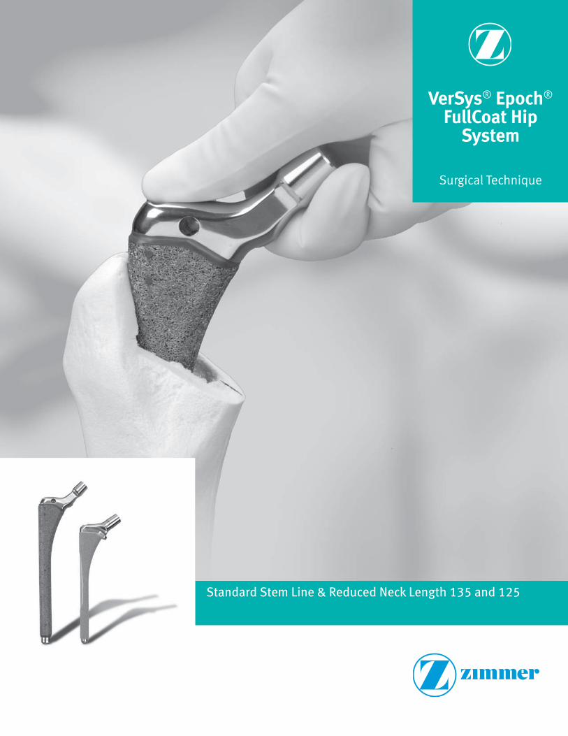
VerSys® Epoch® FullCoat Hip
System
Surgical Technique
Standard Stem Line & Reduced Neck Length 135 and 125

VerSys® Epoch® FullCoat Hip System
1 Using a VerSys Epoch FullCoat Hip
Using a VerSys Epoch FullCoat Hip . . . . . . . . . . . . . . . . . . . . . . . . . . . . . . . . . 1
Epoch Technology . . . . . . . . . . . . . . . . . . . . . . . . . . . . . . . . . . . . . . . . . . . . . . 1
Stem Design . . . . . . . . . . . . . . . . . . . . . . . . . . . . . . . . . . . . . . . . . . . . . . . . . . 1
2 Preoperative Planning
2.1 Templating for the VerSys Epoch FullCoat Hip . . . . . . . . . . . . . . . . . . . . 4
2.2 Femoral Templating . . . . . . . . . . . . . . . . . . . . . . . . . . . . . . . . . . . . . . . . . 6
3 Surgical Technique
3.1 Osteotomize the Femoral Neck . . . . . . . . . . . . . . . . . . . . . . . . . . . . . . . . 7
3.2 Prepare the Femur . . . . . . . . . . . . . . . . . . . . . . . . . . . . . . . . . . . . . . . . . . 8
Opening the Femoral Canal . . . . . . . . . . . . . . . . . . . . . . . . . . . . . . . . . . . 8
Reaming/Rasping. . . . . . . . . . . . . . . . . . . . . . . . . . . . . . . . . . . . . . . . . . . 9
Assessing Rotational Stability . . . . . . . . . . . . . . . . . . . . . . . . . . . . . . . . . 13
3.3 Plane the Calcar (Optional) . . . . . . . . . . . . . . . . . . . . . . . . . . . . . . . . . . . 14
3.4 Perform Trial Reduction . . . . . . . . . . . . . . . . . . . . . . . . . . . . . . . . . . . . . . 14
3.5 Perform Final Reaming. . . . . . . . . . . . . . . . . . . . . . . . . . . . . . . . . . . . . . . 15
3.6 Implant Final Components. . . . . . . . . . . . . . . . . . . . . . . . . . . . . . . . . . . . 16
Assembling the VerSys Epoch FullCoat Stem Inserter . . . . . . . . . . . . . . 16
Inserting the Femoral Component . . . . . . . . . . . . . . . . . . . . . . . . . . . . . . 17
Attaching the Femoral Head. . . . . . . . . . . . . . . . . . . . . . . . . . . . . . . . . . . 19
3.7 Revising Femoral Components . . . . . . . . . . . . . . . . . . . . . . . . . . . . . . . . 19
Extracting with the Looped-Taper Extractor or Hook Extractor . . . . . . . . 19
4 Ordering Information 20
SECTION PAGE
Table of Contents
VerSys® Epoch® FullCoat Hip System Surgical Technique
TOC
1SECTION
1
Using a VerSys Epoch FullCoat HipEpoch Technology
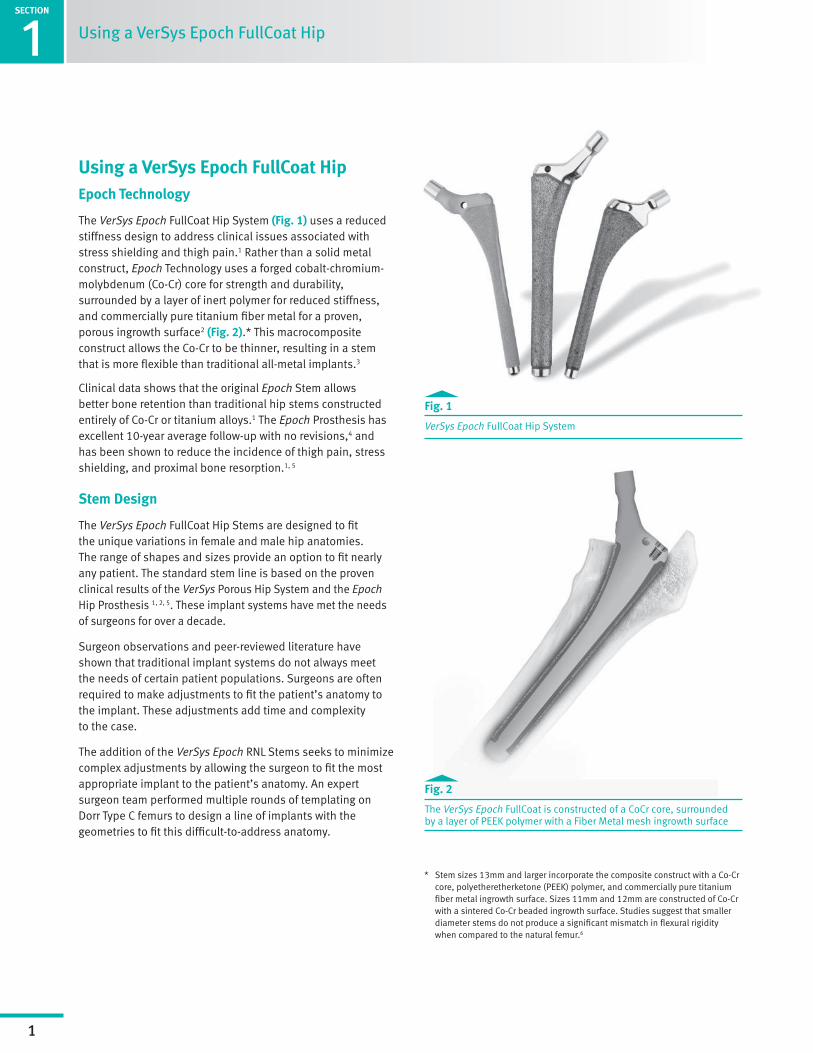
The VerSys Epoch FullCoat Hip System (Fig. 1) uses a reduced stiffness design to address clinical issues associated with stress shielding and thigh pain.1 Rather than a solid metal construct, Epoch Technology uses a forged cobalt-chromium-molybdenum (Co-Cr) core for strength and durability, surrounded by a layer of inert polymer for reduced stiffness, and commercially pure titanium fiber metal for a proven, porous ingrowth surface2 (Fig. 2).* This macrocomposite construct allows the Co-Cr to be thinner, resulting in a stem that is more flexible than traditional all-metal implants.3
Clinical data shows that the original Epoch Stem allows better bone retention than traditional hip stems constructed entirely of Co-Cr or titanium alloys.1 The Epoch Prosthesis has excellent 10-year average follow-up with no revisions,4 and has been shown to reduce the incidence of thigh pain, stress shielding, and proximal bone resorption.1, 5
Stem Design
The VerSys Epoch FullCoat Hip Stems are designed to fit the unique variations in female and male hip anatomies. The range of shapes and sizes provide an option to fit nearly any patient. The standard stem line is based on the proven clinical results of the VerSys Porous Hip System and the Epoch Hip Prosthesis 1, 2, 5. These implant systems have met the needs of surgeons for over a decade.
Surgeon observations and peer-reviewed literature have shown that traditional implant systems do not always meet the needs of certain patient populations. Surgeons are often required to make adjustments to fit the patient’s anatomy to the implant. These adjustments add time and complexity to the case.
The addition of the VerSys Epoch RNL Stems seeks to minimize complex adjustments by allowing the surgeon to fit the most appropriate implant to the patient’s anatomy. An expert surgeon team performed multiple rounds of templating on Dorr Type C femurs to design a line of implants with the geometries to fit this difficult-to-address anatomy.
Fig. 1
VerSys Epoch FullCoat Hip System
Fig. 2
The VerSys Epoch FullCoat is constructed of a CoCr core, surrounded by a layer of PEEK polymer with a Fiber Metal mesh ingrowth surface
* Stem sizes 13mm and larger incorporate the composite construct with a Co-Cr core, polyetheretherketone (PEEK) polymer, and commercially pure titanium fiber metal ingrowth surface. Sizes 11mm and 12mm are constructed of Co-Cr with a sintered Co-Cr beaded ingrowth surface. Studies suggest that smaller diameter stems do not produce a significant mismatch in flexural rigidity when compared to the natural femur.6
Using a VerSys Epoch FullCoat Hip

SECTION
1
2
Using a VerSys Epoch FullCoat Hip
Dorr Type A and B:
Dorr Type A femurs are characterized by the champagne-flute shaped canal with narrow diaphysis. The cortical walls are thick and dense and clearly evident on radiograph. Type B shows some bone loss and widening of the intramedullary canal, but maintains the champagne-flute shape.7 (Fig. 3)
The VerSys Epoch FullCoat standard implants offer multiple metaphyseal sizes and offsets to address the range of femoral anatomies present with Dorr Type A and B femoral anatomy. In addition, the extra-extended offset stems have 12mm of added horizontal offset to address the larger femur.
Fig. 3
Radiograph of A/B bone with appropriate standard template overlaid
3
Using a VerSys Epoch FullCoat Hip
SECTION
1
Dorr Type C:
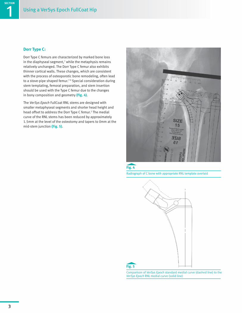
Dorr Type C femurs are characterized by marked bone loss in the diaphyseal segment,7 while the metaphysis remains relatively unchanged. The Dorr Type C femur also exhibits thinner cortical walls. These changes, which are consistent with the process of osteoporotic bone remodeling, often lead to a stove-pipe shaped femur.7-9 Special consideration during stem templating, femoral preparation, and stem insertion should be used with the Type C femur due to the changes in bony composition and geometry (Fig. 4).
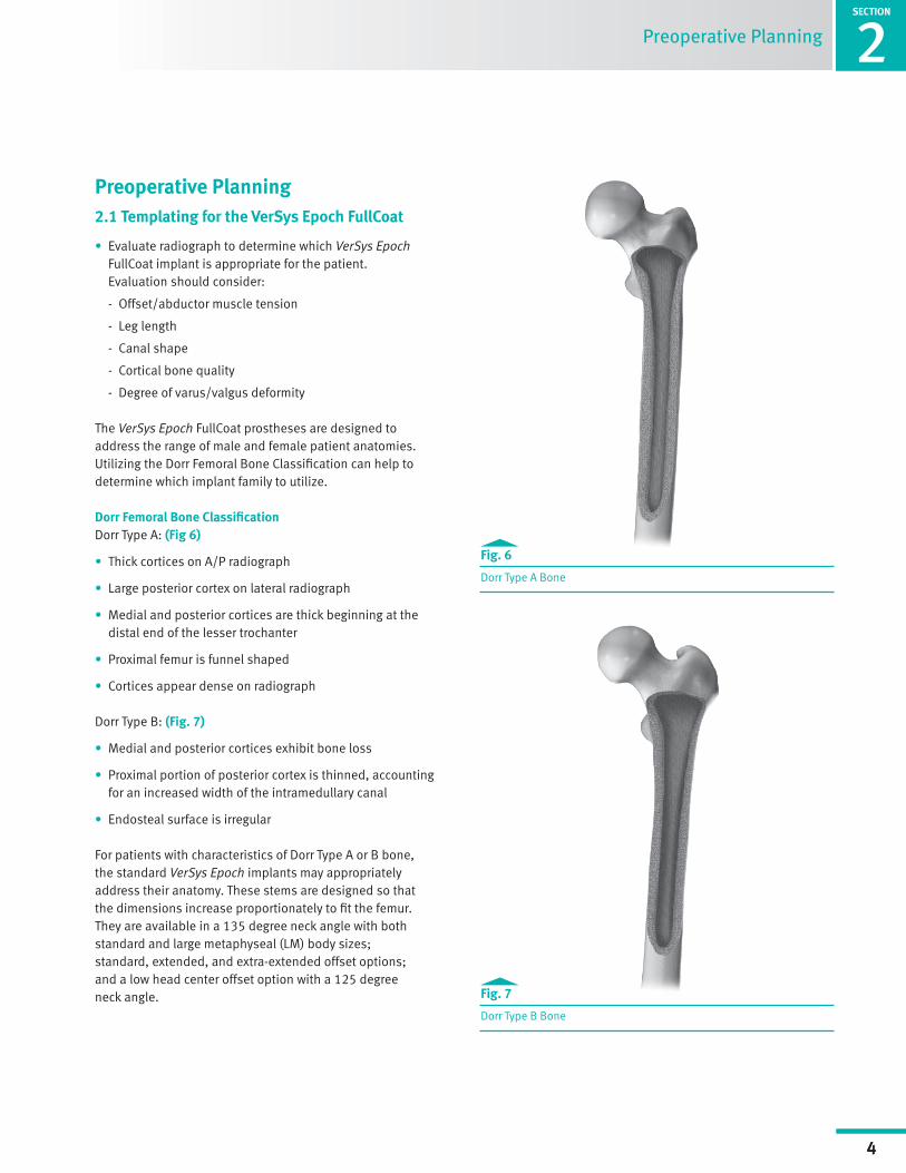
The VerSys Epoch FullCoat RNL stems are designed with smaller metaphyseal segments and shorter head height and head offset to address the Dorr Type C femur.3 The medial curve of the RNL stems has been reduced by approximately 1.5mm at the level of the osteotomy and tapers to 0mm at the mid-stem junction (Fig. 5).
Fig. 4
Radiograph of C bone with appropriate RNL template overlaid
Fig. 5
Comparison of VerSys Epoch standard medial curve (dashed line) to the VerSys Epoch RNL medial curve (solid line)
SECTION
1
4
Surgical Technique Header
SECTION
2
4
Fig. 7
Dorr Type B Bone
Preoperative Planning 2.1 Templating for the VerSys Epoch FullCoat
• Evaluate radiograph to determine which VerSys Epoch FullCoat implant is appropriate for the patient. Evaluation should consider:
- Offset/abductor muscle tension
- Leg length
- Canal shape
- Cortical bone quality
- Degree of varus/valgus deformity
The VerSys Epoch FullCoat prostheses are designed to address the range of male and female patient anatomies. Utilizing the Dorr Femoral Bone Classification can help to determine which implant family to utilize.
Dorr Femoral Bone ClassificationDorr Type A: (Fig 6)
• Thick cortices on A/P radiograph
• Large posterior cortex on lateral radiograph
• Medial and posterior cortices are thick beginning at the distal end of the lesser trochanter
• Proximal femur is funnel shaped
• Cortices appear dense on radiograph
Dorr Type B: (Fig. 7)
• Medial and posterior cortices exhibit bone loss
• Proximal portion of posterior cortex is thinned, accounting for an increased width of the intramedullary canal
• Endosteal surface is irregular
For patients with characteristics of Dorr Type A or B bone, the standard VerSys Epoch implants may appropriately address their anatomy. These stems are designed so that the dimensions increase proportionately to fit the femur. They are available in a 135 degree neck angle with both standard and large metaphyseal (LM) body sizes; standard, extended, and extra-extended offset options; and a low head center offset option with a 125 degree neck angle.
Preoperative Planning
Fig. 6
Dorr Type A Bone
1SECTION
5
Surgical Technique Header2SECTION
5
Preoperative Planning
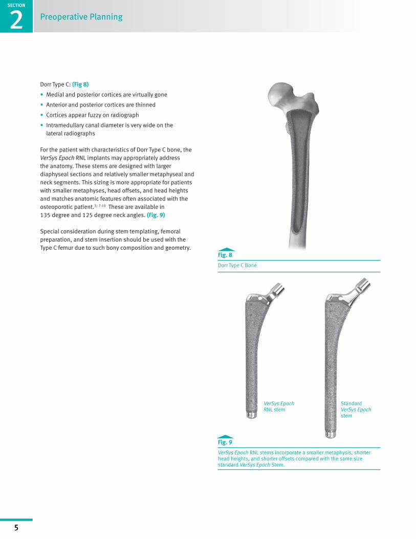
Dorr Type C: (Fig 8)
• Medial and posterior cortices are virtually gone
• Anterior and posterior cortices are thinned
• Cortices appear fuzzy on radiograph
• Intramedullary canal diameter is very wide on the lateral radiographs
For the patient with characteristics of Dorr Type C bone, the VerSys Epoch RNL implants may appropriately address the anatomy. These stems are designed with larger diaphyseal sections and relatively smaller metaphyseal and neck segments. This sizing is more appropriate for patients with smaller metaphyses, head offsets, and head heights and matches anatomic features often associated with the osteoporotic patient.3, 7-10 These are available in 135 degree and 125 degree neck angles. (Fig. 9)
Special consideration during stem templating, femoral preparation, and stem insertion should be used with the Type C femur due to such bony composition and geometry.
Fig. 8
Dorr Type C Bone
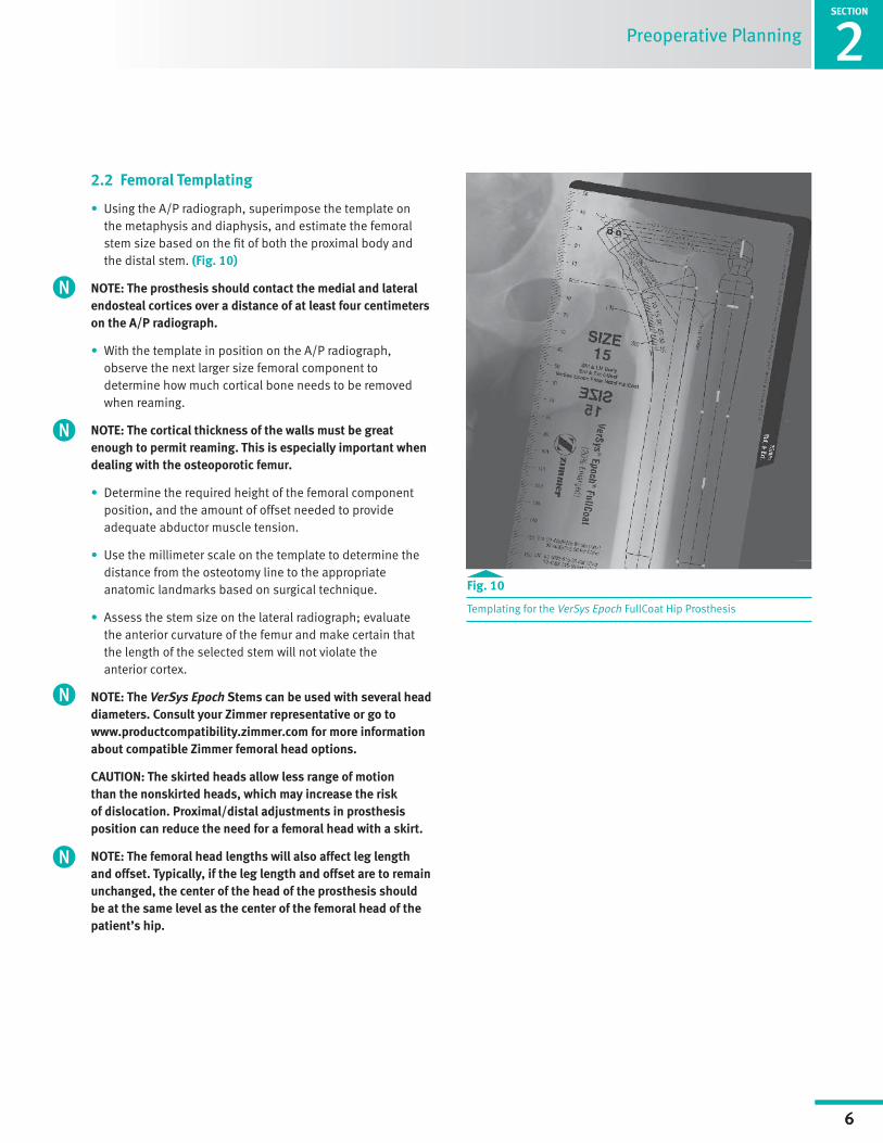
Fig. 9
VerSys Epoch RNL stems incorporate a smaller metaphysis, shorter head heights, and shorter offsets compared with the same size standard VerSys Epoch Stem.
VerSys Epoch RNL stem
Standard VerSys Epoch stem
SECTION
1
6
Surgical Technique Header
SECTION
2
6
Preoperative Planning
Fig. 10
Templating for the VerSys Epoch FullCoat Hip Prosthesis
2.2 Femoral Templating
• Using the A/P radiograph, superimpose the template on the metaphysis and diaphysis, and estimate the femoral stem size based on the fit of both the proximal body and the distal stem. (Fig. 10)
NOTE: The prosthesis should contact the medial and lateral endosteal cortices over a distance of at least four centimeters on the A/P radiograph.
• With the template in position on the A/P radiograph, observe the next larger size femoral component to determine how much cortical bone needs to be removed when reaming.
NOTE: The cortical thickness of the walls must be great enough to permit reaming. This is especially important when dealing with the osteoporotic femur.
• Determine the required height of the femoral component position, and the amount of offset needed to provide adequate abductor muscle tension.
• Use the millimeter scale on the template to determine the distance from the osteotomy line to the appropriate anatomic landmarks based on surgical technique.
• Assess the stem size on the lateral radiograph; evaluate the anterior curvature of the femur and make certain that the length of the selected stem will not violate the anterior cortex.
NOTE: The VerSys Epoch Stems can be used with several head diameters. Consult your Zimmer representative or go to www.productcompatibility.zimmer.com for more information about compatible Zimmer femoral head options.
CAUTION: The skirted heads allow less range of motion than the nonskirted heads, which may increase the risk of dislocation. Proximal/distal adjustments in prosthesis position can reduce the need for a femoral head with a skirt.
NOTE: The femoral head lengths will also affect leg length and offset. Typically, if the leg length and offset are to remain unchanged, the center of the head of the prosthesis should be at the same level as the center of the femoral head of the patient’s hip.
1SECTION
7
Surgical Technique Header
SECTION
7
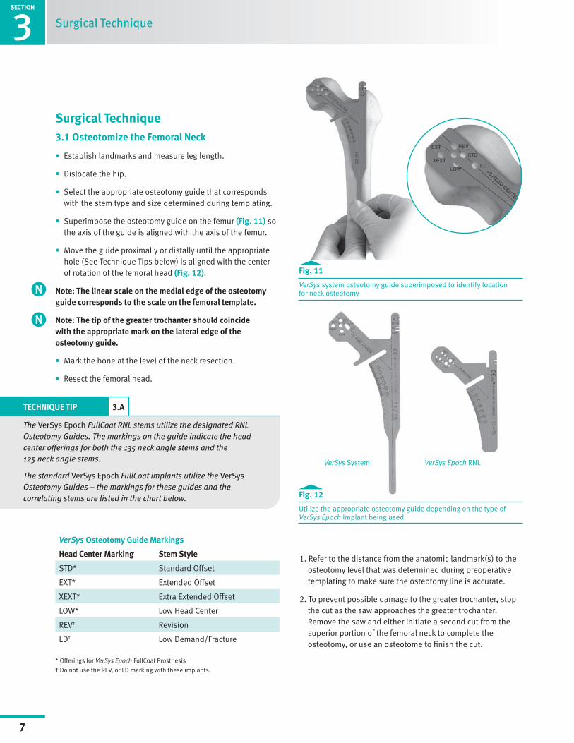
Fig. 11
VerSys system osteotomy guide superimposed to identify location for neck osteotomy
Fig. 12
Utilize the appropriate osteotomy guide depending on the type of VerSys Epoch Implant being used
Surgical Technique
Surgical Technique 3.1 Osteotomize the Femoral Neck
• Establish landmarks and measure leg length.
• Dislocate the hip.
• Select the appropriate osteotomy guide that corresponds with the stem type and size determined during templating.
• Superimpose the osteotomy guide on the femur (Fig. 11) so the axis of the guide is aligned with the axis of the femur.
• Move the guide proximally or distally until the appropriate hole (See Technique Tips below) is aligned with the center of rotation of the femoral head (Fig. 12).
Note: The linear scale on the medial edge of the osteotomy guide corresponds to the scale on the femoral template.
Note: The tip of the greater trochanter should coincide with the appropriate mark on the lateral edge of the osteotomy guide.
• Mark the bone at the level of the neck resection.
• Resect the femoral head.
VerSys Osteotomy Guide Markings
Head Center Marking Stem Style
STD* Standard Offset
EXT* Extended Offset
XEXT* Extra Extended Offset
LOW* Low Head Center
REV† Revision
LD† Low Demand/Fracture
* Offerings for VerSys Epoch FullCoat Prosthesis
† Do not use the REV, or LD marking with these implants.
1. Refer to the distance from the anatomic landmark(s) to the osteotomy level that was determined during preoperative templating to make sure the osteotomy line is accurate.
2. To prevent possible damage to the greater trochanter, stop the cut as the saw approaches the greater trochanter. Remove the saw and either initiate a second cut from the superior portion of the femoral neck to complete the osteotomy, or use an osteotome to finish the cut.
VerSys System VerSys Epoch RNL
TECHNIQUE TIP 3.A
The VerSys Epoch FullCoat RNL stems utilize the designated RNL Osteotomy Guides. The markings on the guide indicate the head center offerings for both the 135 neck angle stems and the 125 neck angle stems.
The standard VerSys Epoch FullCoat implants utilize the VerSys Osteotomy Guides – the markings for these guides and the correlating stems are listed in the chart below.
3

SECTION
1
8
Surgical Technique Header
SECTION
3
8
Surgical Technique
3.2 Prepare the Femur
3.2.1 Opening the Femoral Canal
• Identify the extension of the mid shaft of the femur.
• Use the Box Osteotome (Fig. 13), Trochanteric Reamer, or a burr to remove bone from the medial portion of the greater trochanter and the lateral portion of the femoral neck.
• Insert the Tapered Awl (Fig. 14) or a curette to open the medullary canal.
NOTE: Insufficient space may result in improper stem positioning. However, the space should not be larger than the rasp or implant. Failure to find the longitudinal axis of the femur may result in eccentric reaming of the canal.
TECHNIQUE TIP 3.B
Ensure that the medial aspect of the greater trochanter is adequately cleared to provide sufficient space in this area for the passage of instruments to ensure neutral rasp/implant alignment.
Fig. 14
Tapered Awl used to open medullary canal
Fig. 13
Box osteotome used to remove bone from medial portion of greater trochanter and lateral portion of femoral neck

1SECTION
9
Surgical Technique Header3SECTION
9
Fig. 15
IM reaming should achieve 4cm of distal cortical contact
Fig. 16
The rasp should advance with each blow of the mallet
Fig. 17
The RNL rasp should be examined to ensure the prongs of the clothespin feature are not permanently compressed
Surgical Technique
3.2.2 Reaming/Rasping
Bone Types and ReamingThe method of reaming should be chosen based on the patient’s bone quality and surgeon preference. Proper reaming is essential to ensure adequate initial mechanical stability and contact of the ingrowth surface with viable host bone while avoiding fracture, cortical thinning from eccentric reaming, and perforation. With that in mind, bone classification will play an important role in determining the final reaming dimension for implanting the VerSys Epoch Stems in Dorr Type C femurs or osteoporotic bone.
• Under-reaming by 0.25mm should be appropriate for most bone types.
• For softer bone, under-reaming by 0.5mm may allow better mechanical stability and implant-to-bone apposition.
• Line-to-line reaming should only be used with very hard bone.
• In all situations, it is essential that 4cm of cortical contact and initial mechanical stability be achieved.
Reaming and Rasping Progression – Technique Outline
• Begin reaming by hand, using the T-Handle, until reaming becomes difficult.
• Then ream using power in 0.5mm increments up to 2.5mm below the templated implant size. (Fig. 15)
• Insert the rasp that is 2 sizes below the templated implant size. Ensure that the rasp advances with each blow of the mallet. (Fig. 16)
NOTE: After each use, the clothespin feature of the RNL Rasps should be checked to ensure that the prongs are not permanently compressed. (Fig. 17)
• Assess the fit, determining whether reaming and rasping should continue.
SECTION
1
10
Surgical Technique Header
SECTION
3
10
• Continue reaming in 0.5mm increments while assessing the progressive reaming and rasp fit. Reaming should begin to remove cortical bone, leaving hard bone debris on the reamer upon removal. It is important to achieve a minimum of 4cm of distal press-fit of the final implant as judged during reaming.
• Continue the reaming and rasping progression until appropriate distal press-fit is achieved with the reamer and the final rasp appropriately fits the proximal femur. The last reamer used at this stage should be 0.5mm under the final implant size.
• After trial reduction and before stem insertion, the canal should be reamed to 0.25mm under the final implant size. For the smaller beaded stems, reaming to 0.5mm under may be appropriate depending on bone type. Ensure the canal is reamed to the appropriate depth, depending on the implant being used.
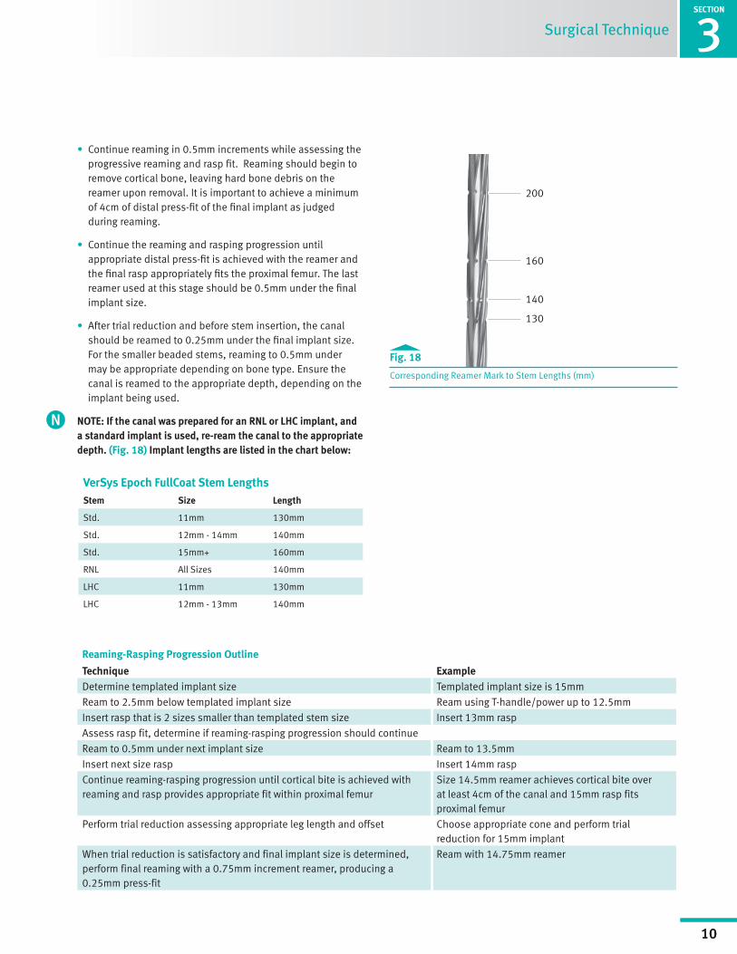
NOTE: If the canal was prepared for an RNL or LHC implant, and a standard implant is used, re-ream the canal to the appropriate depth. (Fig. 18) Implant lengths are listed in the chart below:
Fig. 18
Corresponding Reamer Mark to Stem Lengths (mm)
VerSys Epoch FullCoat Stem LengthsStem Size Length
Std. 11mm 130mm
Std. 12mm - 14mm 140mm
Std. 15mm+ 160mm
RNL All Sizes 140mm
LHC 11mm 130mm
LHC 12mm - 13mm 140mm
Surgical Technique
200
160
140
130
Reaming-Rasping Progression Outline
Technique ExampleDetermine templated implant size Templated implant size is 15mm
Ream to 2.5mm below templated implant size Ream using T-handle/power up to 12.5mm
Insert rasp that is 2 sizes smaller than templated stem size Insert 13mm rasp
Assess rasp fit, determine if reaming-rasping progression should continue
Ream to 0.5mm under next implant size Ream to 13.5mm
Insert next size rasp Insert 14mm rasp
Continue reaming-rasping progression until cortical bite is achieved with reaming and rasp provides appropriate fit within proximal femur
Size 14.5mm reamer achieves cortical bite over at least 4cm of the canal and 15mm rasp fits proximal femur
Perform trial reduction assessing appropriate leg length and offset Choose appropriate cone and perform trial reduction for 15mm implant
When trial reduction is satisfactory and final implant size is determined, perform final reaming with a 0.75mm increment reamer, producing a 0.25mm press-fit
Ream with 14.75mm reamer

1SECTION
11
Surgical Technique Header3SECTION
11
A/P View M/L View
0.5mm press-fit per surface
no press-fit
Surgical Technique
TECHNIQUE TIP 3.C
To measure the amount of cortical press-fit, insert the line-to-line reamer firmly by hand. Measure the amount of reamer exposed above the osteotomy up to the appropriate depth mark that corresponds with the stem length. (Example: the 15mm standard stem is 160mm in length, which corresponds to the 2nd mark from the top of the reamer). (Fig. 19)
VerSys Epoch Rasps:All VerSys Epoch Rasps are sized to provide a built-in 0.5mm press fit on each side of the proximal body of the final implant, resulting in a maximum press fit of 1.0mm in both the A/P and M/L dimensions. The area of press fit begins at the metaphyseal curve junction and gradually increases to 0.5mm at the top of the porous surface. (Fig. 20)
Fig. 20
The VerSys Epoch stems incorporate a built-in press-fit
Fig. 19
Measure the amount of exposed reamer above the osteotomy to ensure 4cm of distal cortical contact
4cm
SECTION
1
12
Surgical Technique Header
SECTION
3
12
Surgical Technique
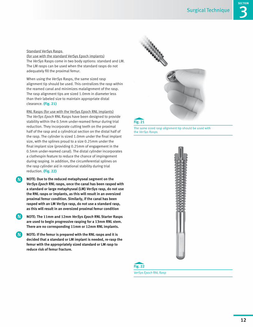
Fig. 21
The same sized rasp alignment tip should be used with the VerSys Rasps
Standard VerSys Rasps (for use with the standard VerSys Epoch implants)The VerSys Rasps come in two body options: standard and LM. The LM rasps can be used when the standard rasps do not adequately fill the proximal femur.
When using the VerSys Rasps, the same sized rasp alignment tip should be used. This centralizes the rasp within the reamed canal and minimizes malalignment of the rasp. The rasp alignment tips are sized 1.0mm in diameter less than their labeled size to maintain appropriate distal clearance. (Fig. 21)
RNL Rasps (for use with the VerSys Epoch RNL implants)The VerSys Epoch RNL Rasps have been designed to provide stability within the 0.5mm under-reamed femur during trial reduction. They incorporate cutting teeth on the proximal half of the rasp and a cylindrical section on the distal half of the rasp. The cylinder is sized 1.0mm under the final implant size, with the splines proud to a size 0.25mm under the final implant size (providing 0.25mm of engagement in the 0.5mm under-reamed canal). The distal cylinder incorporates a clothespin feature to reduce the chance of impingement during rasping. In addition, the circumferential splines on the rasp cylinder aid in rotational stability during trial reduction. (Fig. 22)
NOTE: Due to the reduced metaphyseal segment on the VerSys Epoch RNL rasps, once the canal has been rasped with a standard or large metaphyseal (LM) VerSys rasp, do not use the RNL rasps or implants, as this will result in an oversized proximal femur condition. Similarly, if the canal has been rasped with an LM VerSys rasp, do not use a standard rasp, as this will result in an oversized proximal femur condition
NOTE: The 11mm and 12mm VerSys Epoch RNL Starter Rasps are used to begin progressive rasping for a 13mm RNL stem. There are no corresponding 11mm or 12mm RNL implants.
NOTE: If the femur is prepared with the RNL rasps and it is decided that a standard or LM implant is needed, re-rasp the femur with the appropriately sized standard or LM rasp to reduce risk of femur fracture.
Fig. 22
VerSys Epoch RNL Rasp
1SECTION
13
Surgical Technique Header3SECTION
13
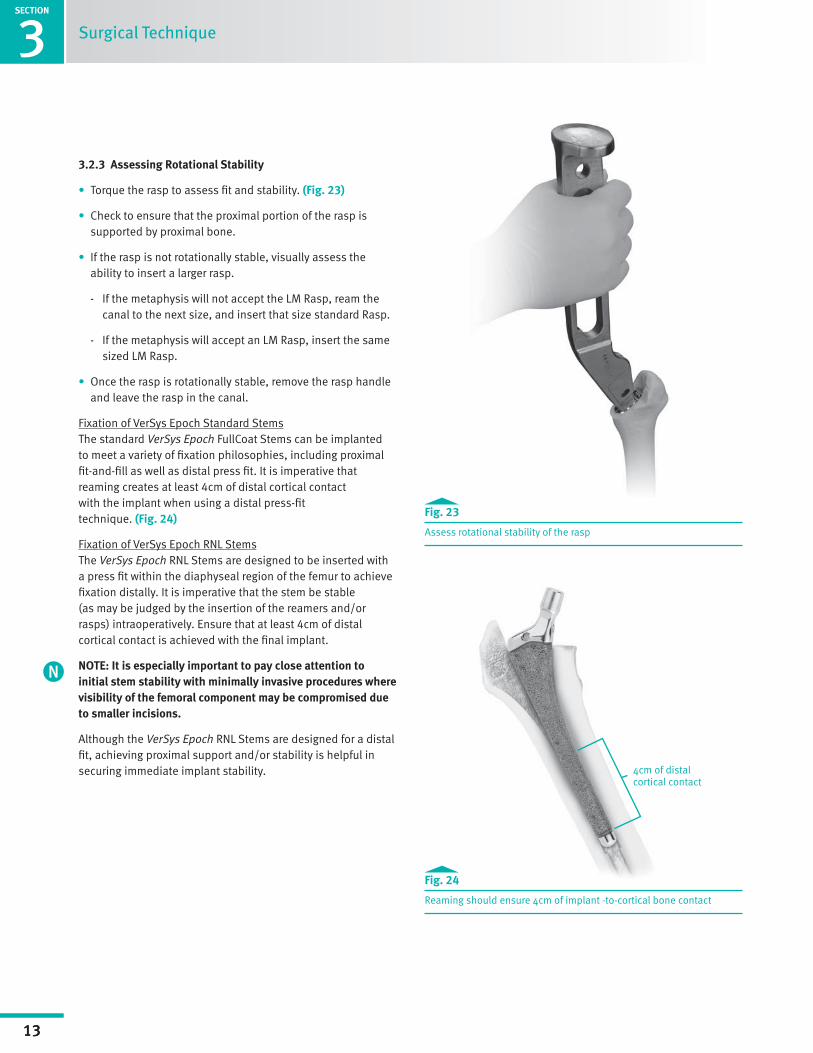
Fig. 23
Assess rotational stability of the rasp
Fig. 24
Reaming should ensure 4cm of implant -to-cortical bone contact
Surgical Technique
3.2.3 Assessing Rotational Stability
• Torque the rasp to assess fit and stability. (Fig. 23)
• Check to ensure that the proximal portion of the rasp is supported by proximal bone.
• If the rasp is not rotationally stable, visually assess the ability to insert a larger rasp.
- If the metaphysis will not accept the LM Rasp, ream the canal to the next size, and insert that size standard Rasp.
- If the metaphysis will accept an LM Rasp, insert the same sized LM Rasp.
• Once the rasp is rotationally stable, remove the rasp handle and leave the rasp in the canal.
Fixation of VerSys Epoch Standard StemsThe standard VerSys Epoch FullCoat Stems can be implanted to meet a variety of fixation philosophies, including proximal fit-and-fill as well as distal press fit. It is imperative that reaming creates at least 4cm of distal cortical contact with the implant when using a distal press-fit technique. (Fig. 24)
Fixation of VerSys Epoch RNL StemsThe VerSys Epoch RNL Stems are designed to be inserted with a press fit within the diaphyseal region of the femur to achieve fixation distally. It is imperative that the stem be stable (as may be judged by the insertion of the reamers and/or rasps) intraoperatively. Ensure that at least 4cm of distal cortical contact is achieved with the final implant.
NOTE: It is especially important to pay close attention to initial stem stability with minimally invasive procedures where visibility of the femoral component may be compromised due to smaller incisions.
Although the VerSys Epoch RNL Stems are designed for a distal fit, achieving proximal support and/or stability is helpful in securing immediate implant stability. 4cm of distal
cortical contact
SECTION
1
14
Surgical Technique Header
SECTION
3
14
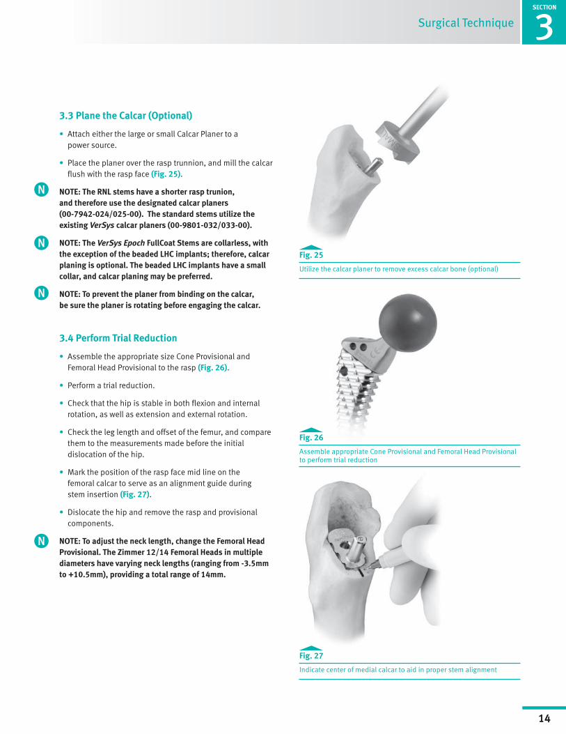
3.3 Plane the Calcar (Optional)
• Attach either the large or small Calcar Planer to a power source.
• Place the planer over the rasp trunnion, and mill the calcar flush with the rasp face (Fig. 25).
NOTE: The RNL stems have a shorter rasp trunion, and therefore use the designated calcar planers (00-7942-024/025-00). The standard stems utilize the existing VerSys calcar planers (00-9801-032/033-00).
NOTE: The VerSys Epoch FullCoat Stems are collarless, with the exception of the beaded LHC implants; therefore, calcar planing is optional. The beaded LHC implants have a small collar, and calcar planing may be preferred.
NOTE: To prevent the planer from binding on the calcar, be sure the planer is rotating before engaging the calcar.
3.4 Perform Trial Reduction
• Assemble the appropriate size Cone Provisional and Femoral Head Provisional to the rasp (Fig. 26).
• Perform a trial reduction.
• Check that the hip is stable in both flexion and internal rotation, as well as extension and external rotation.
• Check the leg length and offset of the femur, and compare them to the measurements made before the initial dislocation of the hip.
• Mark the position of the rasp face mid line on the femoral calcar to serve as an alignment guide during stem insertion (Fig. 27).
• Dislocate the hip and remove the rasp and provisional components.
NOTE: To adjust the neck length, change the Femoral Head Provisional. The Zimmer 12/14 Femoral Heads in multiple diameters have varying neck lengths (ranging from -3.5mm to +10.5mm), providing a total range of 14mm.
Fig. 25
Utilize the calcar planer to remove excess calcar bone (optional)
Fig. 26
Assemble appropriate Cone Provisional and Femoral Head Provisional to perform trial reduction
Fig. 27
Indicate center of medial calcar to aid in proper stem alignment
Surgical Technique
1SECTION
15
Surgical Technique Header3SECTION
15
Surgical Technique
TECHNIQUE TIP 3.D
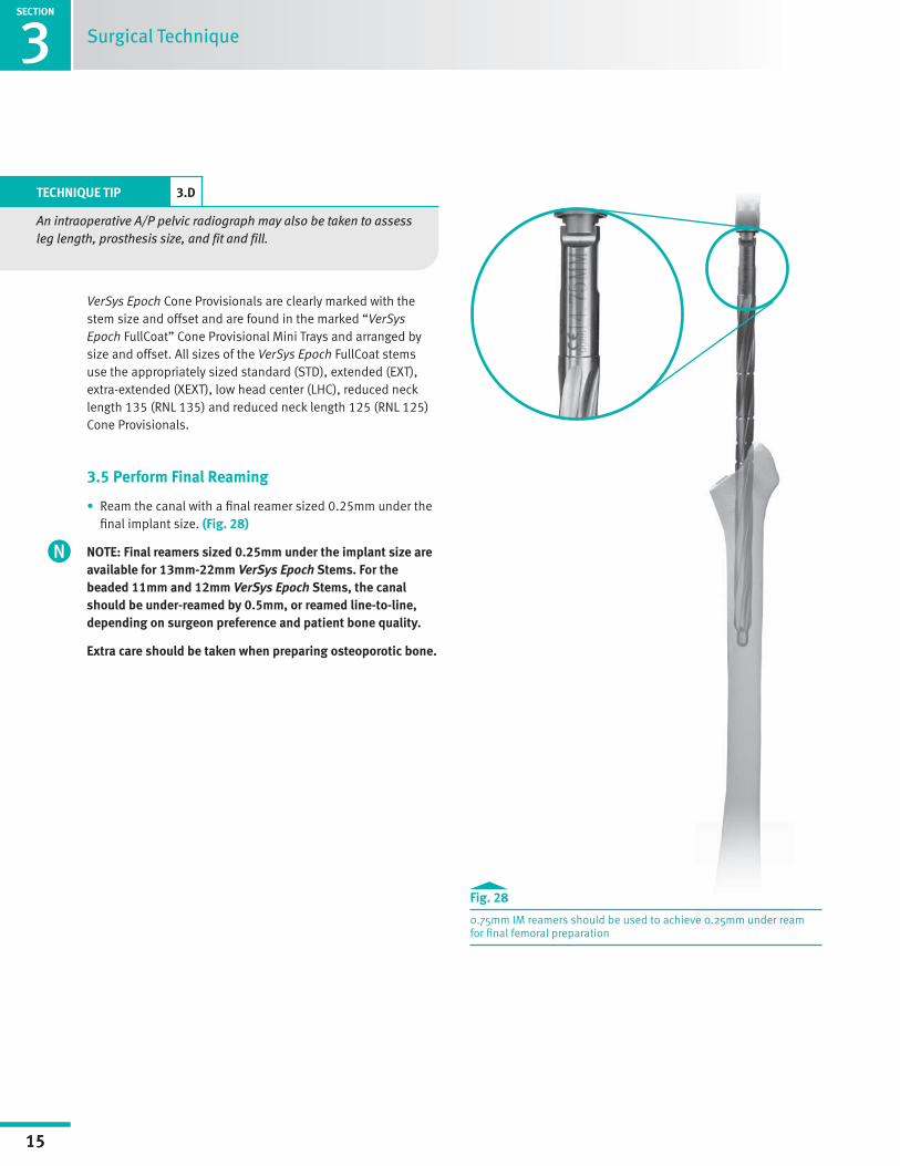
An intraoperative A/P pelvic radiograph may also be taken to assess leg length, prosthesis size, and fit and fill.
VerSys Epoch Cone Provisionals are clearly marked with the stem size and offset and are found in the marked “VerSys Epoch FullCoat” Cone Provisional Mini Trays and arranged by size and offset. All sizes of the VerSys Epoch FullCoat stems use the appropriately sized standard (STD), extended (EXT), extra-extended (XEXT), low head center (LHC), reduced neck length 135 (RNL 135) and reduced neck length 125 (RNL 125) Cone Provisionals.
3.5 Perform Final Reaming
• Ream the canal with a final reamer sized 0.25mm under the final implant size. (Fig. 28)
NOTE: Final reamers sized 0.25mm under the implant size are available for 13mm-22mm VerSys Epoch Stems. For the beaded 11mm and 12mm VerSys Epoch Stems, the canal should be under-reamed by 0.5mm, or reamed line-to-line, depending on surgeon preference and patient bone quality.
Extra care should be taken when preparing osteoporotic bone.
Fig. 28
0.75mm IM reamers should be used to achieve 0.25mm under ream for final femoral preparation

SECTION
1
16
Surgical Technique Header
SECTION
3
16
Surgical Technique
3.6 Implant Final Components
3.6.1 Assembling the VerSys Epoch FullCoat Stem Inserter
• Fully thread the Stem Inserter Inner Threaded Rod into the cannulated Stem Inserter Handle (Fig. 29).
• Insert the keyed tip of the Stem Inserter Handle into the mating insertion hole on the stem shoulder (Fig. 30).
• Turn the strike plate on the Stem Inserter Inner Threaded Rod clockwise until the threads on the tip of the rod fully engage the threads in the insertion hole on the stem (Fig. 31).
NOTE: The threads must be fully engaged to avoid potential damage to the Stem Inserter assembly, and to ensure that the strike plate is fully seated against the impactor plate on the Stem Inserter Handle. Light intraoperative extraction may be performed with the fully assembled stem inserter.
Fig. 29
Assembled stem inserter
Fig. 30
Insertion of the VerSys Epoch FullCoat
Fig. 31
Ensure threads are fully engaged into the stem inserter feature on the implant and that the Strike Plate is fully seated against the Impactor Plate
1SECTION
17
Surgical Technique Header3SECTION
17
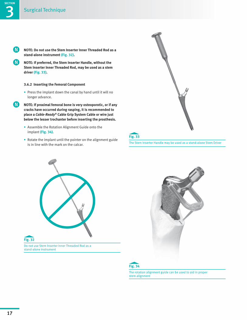
NOTE: Do not use the Stem Inserter Inner Threaded Rod as a stand-alone instrument (Fig. 32).
NOTE: If preferred, the Stem Inserter Handle, without the Stem Inserter Inner Threaded Rod, may be used as a stem driver (Fig. 33).
3.6.2 Inserting the Femoral Component
• Press the implant down the canal by hand until it will no longer advance.
NOTE: If proximal femoral bone is very osteoporotic, or if any cracks have occurred during rasping, it is recommended to place a Cable-Ready® Cable Grip System Cable or wire just below the lesser trochanter before inserting the prosthesis.
• Assemble the Rotation Alignment Guide onto the implant (Fig. 34).
• Rotate the implant until the pointer on the alignment guide is in line with the mark on the calcar.
Surgical Technique
Fig. 34
The rotation alignment guide can be used to aid in proper stem alignment
Fig. 32
Do not use Stem Inserter Inner Threaded Rod as a stand-alone instrument
Fig. 33
The Stem Inserter Handle may be used as a stand-alone Stem Driver
SECTION
1
18
Surgical Technique Header
SECTION
3
18
SECTION
Surgical Technique
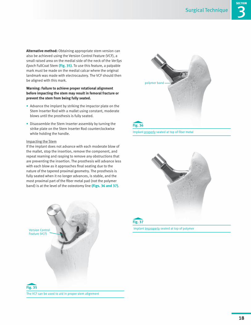
Alternative method: Obtaining appropriate stem version can also be achieved using the Version Control Feature (VCF), a small raised area on the medial side of the neck of the VerSys Epoch FullCoat Stem (Fig. 35). To use this feature, a palpable mark must be made on the medial calcar where the original landmark was made with electrocautery. The VCF should then be aligned with this mark.
Warning: Failure to achieve proper rotational alignment before impacting the stem may result in femoral fracture or prevent the stem from being fully seated.
• Advance the implant by striking the impactor plate on the Stem Inserter Rod with a mallet using constant, moderate blows until the prosthesis is fully seated.
• Disassemble the Stem Inserter assembly by turning the strike plate on the Stem Inserter Rod counterclockwise while holding the handle.
Impacting the StemIf the implant does not advance with each moderate blow of the mallet, stop the insertion, remove the component, and repeat reaming and rasping to remove any obstructions that are preventing the insertion. The prosthesis will advance less with each blow as it approaches final seating due to the nature of the tapered proximal geometry. The prosthesis is fully seated when it no longer advances, is stable, and the most proximal part of the fiber metal pad (not the polymer band) is at the level of the osteotomy line (Figs. 36 and 37).
Version Control Feature (VCF)
Fig. 35
The VCF can be used to aid in proper stem alignment
polymer band
Fig. 36
Implant properly seated at top of fiber metal
Fig. 37
Implant improperly seated at top of polymer

1SECTION
19
Surgical Technique Header3SECTION
19
3.6.3 Attaching the Femoral Head
• Place the selected Femoral Head Provisional onto the taper of the implant.
• Perform a final trial reduction to assess joint stability, range of motion, and restoration of leg length and offset.
• When the appropriate femoral head implant is confirmed, remove the Femoral Head Provisional.
• Check to ensure that the 12/14 taper on the stem is clean and dry.
• Place the selected femoral head onto the taper and secure it firmly by twisting it and striking it once with the Head Impactor.
NOTE: The taper mechanism will engage properly only with the impaction force of a single blow. Successive impaction blows may either disrupt the taper connection or risk femoral fracture.
NOTE: Do not impact the femoral head onto the taper before driving in the prosthesis as the femoral head may loosen during impaction.
• Test the security of the head fixation by trying to remove the head by hand.
• Reduce the hip and assess leg length, range of motion, stability, and abductor tension for the final time.
3.7 Revising Femoral Components
3.7.1 Extracting the Femoral Component with the Looped-Taper Extractor or Hook Extractor
• Attach either the Looped-Taper Extractor to the Slap Hammer Adapter.
• Screw the assembly to the Slap Hammer (Fig. 38). Or thread the Hook Extractor directly to the Slap Hammer.
• Use the Slap Hammer to remove the component (Fig. 39).
Caution: If implant or implant extraction hole is damaged, do not re-insert.
Surgical Technique
Fig. 38
Components of extractor assembly
Fig. 39
Extract the femoral component
SECTION
1
20
Surgical Technique Header
SECTION
4
20
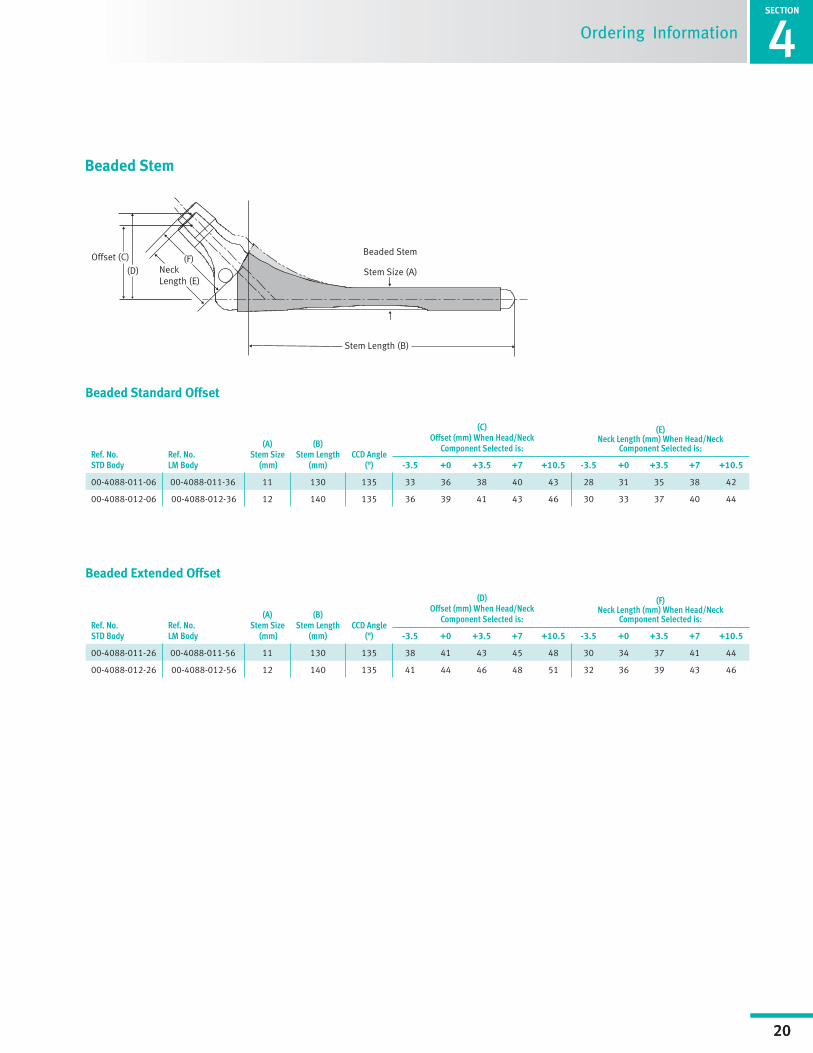
Ordering Information
Ref. No.STD Body
Ref. No.LM Body
(A) Stem Size
(mm)
(B) Stem Length
(mm)CCD Angle
(°)
(C) Offset (mm) When Head/Neck
Component Selected is:
(E) Neck Length (mm) When Head/Neck
Component Selected is:
-3.5 +0 +3.5 +7 +10.5 -3.5 +0 +3.5 +7 +10.5
00-4088-011-06 00-4088-011-36 11 130 135 33 36 38 40 43 28 31 35 38 42
00-4088-012-06 00-4088-012-36 12 140 135 36 39 41 43 46 30 33 37 40 44
Beaded Standard Offset
Beaded Extended Offset
Stem Length (B)
Offset (C)
Neck Length (E)
Stem Size (A) (F)
(D)
Stem Size (A)
Beaded StemOffset (C)
(D)
Stem Length (B)
Neck Length (E)
(F)
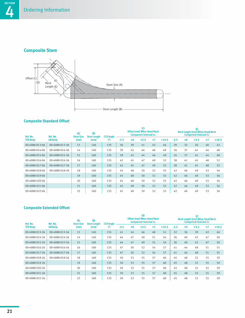
Composite Stem
Beaded Stem
Ref. No.STD Body
Ref. No.LM Body
(A) Stem Size
(mm)
(B) Stem Length
(mm)CCD Angle
(°)
(D) Offset (mm) When Head/Neck
Component Selected is:
(F) Neck Length (mm) When Head/Neck
Component Selected is:
-3.5 +0 +3.5 +7 +10.5 -3.5 +0 +3.5 +7 +10.5
00-4088-011-26 00-4088-011-56 11 130 135 38 41 43 45 48 30 34 37 41 44
00-4088-012-26 00-4088-012-56 12 140 135 41 44 46 48 51 32 36 39 43 46
1SECTION
21
Surgical Technique Header4SECTION
21
Stem Length (B)
Offset (C)
Neck Length (E)
Stem Size (A) (F)
(D)
Stem Size (A)
Beaded StemOffset (C)
(D)
Stem Length (B)
Neck Length (E)
(F)
Composite Stem
Composite Standard Offset
Composite Extended Offset
Composite Stem
Ordering Information
Ref. No.STD Body
Ref. No.LM Body
(A) Stem Size
(mm)
(B) Stem Length
(mm)CCD Angle
(°)
(C) Offset (mm) When Head/Neck
Component Selected is:
(E) Neck Length (mm) When Head/Neck
Component Selected is:
-3.5 +0 +3.5 +7 +10.5 -3.5 +0 +3.5 +7 +10.5
00-4088-013-06 00-4088-013-36 13 140 135 36 39 41 43 46 29 33 36 40 43
00-4088-014-06 00-4088-014-36 14 140 135 39 42 44 46 49 34 37 41 44 48
00-4088-015-06 00-4088-015-36 15 160 135 39 42 44 46 49 34 37 41 44 48
00-4088-016-06 00-4088-016-36 16 160 135 42 45 47 49 52 38 41 45 48 52
00-4088-017-06 00-4088-017-36 17 160 135 42 45 47 49 52 38 41 45 48 52
00-4088-018-06 00-4088-018-36 18 160 135 45 48 50 52 55 42 46 49 53 56
00-4088-019-06 19 160 135 45 48 50 52 55 42 46 49 53 56
00-4088-020-06 20 160 135 45 48 50 52 55 42 46 49 53 56
00-4088-021-06 21 160 135 45 48 50 52 55 42 46 49 53 56
00-4088-022-06 22 160 135 45 48 50 52 55 42 46 49 53 56
Ref. No.STD Body
Ref. No.LM Body
(A) Stem Size
(mm)
(B) Stem Length
(mm)CCD Angle
(°)
(D) Offset (mm) When Head/Neck
Component Selected is:
(F) Neck Length (mm) When Head/Neck
Component Selected is:
-3.5 +0 +3.5 +7 +10.5 -3.5 +0 +3.5 +7 +10.5
00-4088-013-26 00-4088-013-56 13 140 135 41 44 46 48 51 32 36 39 43 46
00-4088-014-26 00-4088-014-56 14 140 135 44 47 49 51 54 36 40 43 47 50
00-4088-015-26 00-4088-015-56 15 160 135 44 47 49 51 54 36 40 43 47 50
00-4088-016-26 00-4088-016-56 16 160 135 47 50 52 54 57 41 44 48 51 55
00-4088-017-26 00-4088-017-56 17 160 135 47 50 52 54 57 41 44 48 51 55
00-4088-018-26 00-4088-018-56 18 160 135 50 53 55 57 60 45 48 52 55 59
00-4088-019-26 19 160 135 50 53 55 57 60 45 48 52 55 59
00-4088-020-26 20 160 135 50 53 55 57 60 45 48 52 55 59
00-4088-021-26 21 160 135 50 53 55 57 60 45 48 52 55 59
00-4088-022-26 22 160 135 50 53 55 57 60 45 48 52 55 59
SECTION
1
22
Surgical Technique Header
SECTION
4
22
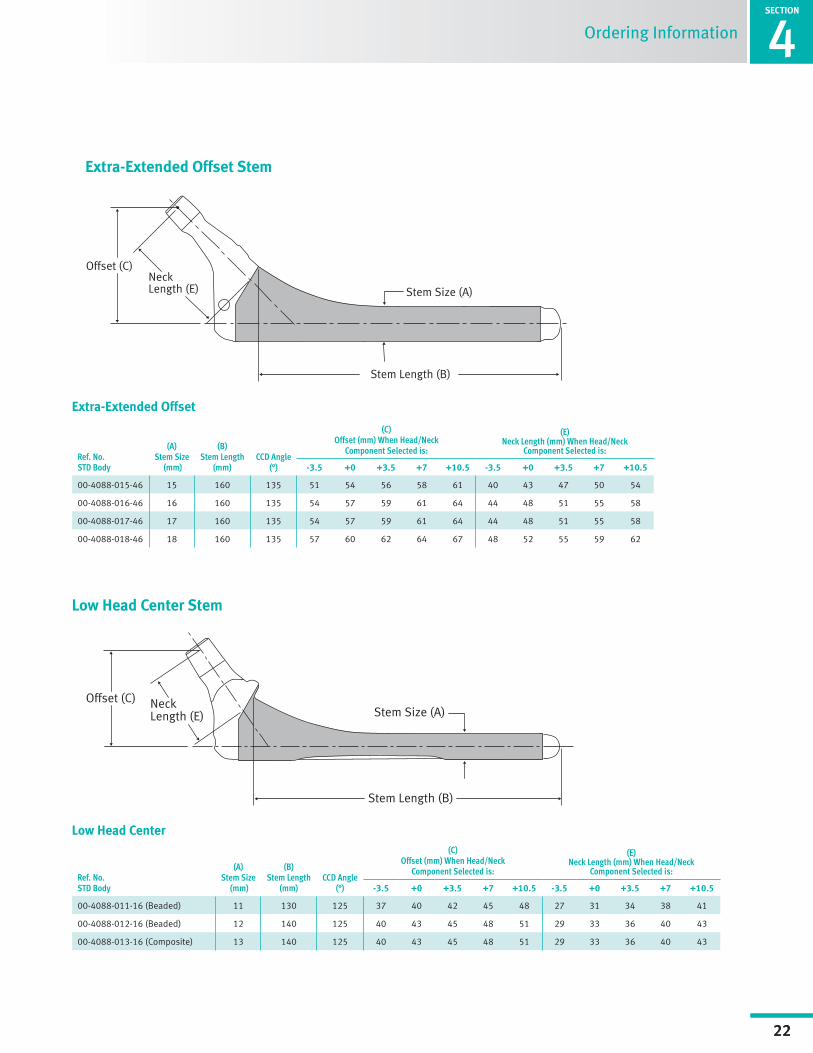
Ordering Information
Extra-Extended Offset Stem
Low Head Center Stem
Ref. No.STD Body
(A) Stem Size
(mm)
(B) Stem Length
(mm)CCD Angle
(°)
(C) Offset (mm) When Head/Neck
Component Selected is:
(E) Neck Length (mm) When Head/Neck
Component Selected is:
-3.5 +0 +3.5 +7 +10.5 -3.5 +0 +3.5 +7 +10.5
00-4088-015-46 15 160 135 51 54 56 58 61 40 43 47 50 54
00-4088-016-46 16 160 135 54 57 59 61 64 44 48 51 55 58
00-4088-017-46 17 160 135 54 57 59 61 64 44 48 51 55 58
00-4088-018-46 18 160 135 57 60 62 64 67 48 52 55 59 62
Extra-Extended Offset
Ref. No.STD Body
(A) Stem Size
(mm)
(B) Stem Length
(mm)CCD Angle
(°)
(C) Offset (mm) When Head/Neck
Component Selected is:
(E) Neck Length (mm) When Head/Neck
Component Selected is:
-3.5 +0 +3.5 +7 +10.5 -3.5 +0 +3.5 +7 +10.5
00-4088-011-16 (Beaded) 11 130 125 37 40 42 45 48 27 31 34 38 41
00-4088-012-16 (Beaded) 12 140 125 40 43 45 48 51 29 33 36 40 43
00-4088-013-16 (Composite) 13 140 125 40 43 45 48 51 29 33 36 40 43
Low Head Center
1SECTION
23
Surgical Technique Header4SECTION
23
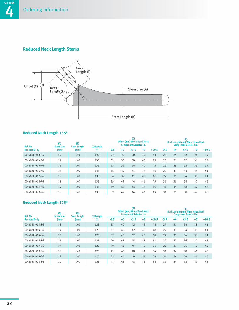
Ordering Information
Reduced Neck Length Stems
Ref. No.Reduced Body
(A) Stem Size
(mm)
(B) Stem Length
(mm)CCD Angle
(°)
(C) Offset (mm) When Head/Neck
Component Selected is:
(E) Neck Length (mm) When Head/Neck
Component Selected is:
-3.5 +0 +3.5 +7 +10.5 -3.5 +0 +3.5 +7 +10.5
00-4088-013-76 13 140 135 33 36 38 40 43 25 29 32 36 39
00-4088-014-76 14 140 135 33 36 38 40 43 25 29 32 36 39
00-4088-015-76 15 140 135 33 36 38 40 43 25 29 32 36 39
00-4088-016-76 16 140 135 36 39 41 43 46 27 31 34 38 41
00-4088-017-76 17 140 135 36 39 41 43 46 27 31 34 38 41
00-4088-018-76 18 140 135 39 42 44 46 49 31 35 38 42 45
00-4088-019-86 19 140 135 39 42 44 46 49 31 35 38 42 45
00-4088-020-76 20 140 135 39 42 44 46 49 31 35 38 42 45
Reduced Neck Length 135°
Ref. No.Reduced Body
(A) Stem Size
(mm)
(B) Stem Length
(mm)CCD Angle
(°)
(D) Offset (mm) When Head/Neck
Component Selected is:
(F) Neck Length (mm) When Head/Neck
Component Selected is:
-3.5 +0 +3.5 +7 +10.5 -3.5 +0 +3.5 +7 +10.5
00-4088-013-86 13 140 125 37 40 42 45 48 27 31 34 38 41
00-4088-014-86 14 140 125 37 40 42 45 48 27 31 34 38 41
00-4088-015-86 15 140 125 37 40 42 45 48 27 31 34 38 41
00-4088-016-86 16 140 125 40 43 45 48 51 29 33 36 40 43
00-4088-017-86 17 140 125 40 43 45 48 51 29 33 36 40 43
00-4088-018-86 18 140 125 43 46 48 51 54 31 34 38 41 45
00-4088-019-86 19 140 125 43 46 48 51 54 31 34 38 41 45
00-4088-020-86 20 140 125 43 46 48 51 54 31 34 38 41 45
Reduced Neck Length 125°

SECTION
1
24
Surgical Technique Header
SECTION
4
24
Ordering Information
Standard Body, Standard OffsetItem Number Description
Beaded Stems
00-4088-011-06 VerSys Epoch FullCoat Stem 11 STD
00-4088-012-06 VerSys Epoch FullCoat Stem 12 STD
Composite Stems
00-4088-013-06 VerSys Epoch FullCoat Stem 13 STD
00-4088-014-06 VerSys Epoch FullCoat Stem 14 STD
00-4088-015-06 VerSys Epoch FullCoat Stem 15 STD
00-4088-016-06 VerSys Epoch FullCoat Stem 16 STD
00-4088-017-06 VerSys Epoch FullCoat Stem 17 STD
00-4088-018-06 VerSys Epoch FullCoat Stem 18 STD
00-4088-019-06 VerSys Epoch FullCoat Stem 19 STD
00-4088-020-06 VerSys Epoch FullCoat Stem 20 STD
00-4088-021-06 VerSys Epoch FullCoat Stem 21 STD
00-4088-022-06 VerSys Epoch FullCoat Stem 22 STD
VerSys Epoch Implants
Standard Body, Extended OffsetItem Number Description
Beaded Stems
00-4088-011-26 VerSys Epoch FullCoat Stem 11 EXT
00-4088-012-26 VerSys Epoch FullCoat Stem 12 EXT
Composite Stems
00-4088-013-26 VerSys Epoch FullCoat Stem 13 EXT
00-4088-014-26 VerSys Epoch FullCoat Stem 14 EXT
00-4088-015-26 VerSys Epoch FullCoat Stem 15 EXT
00-4088-016-26 VerSys Epoch FullCoat Stem 16 EXT
00-4088-017-26 VerSys Epoch FullCoat Stem 17 EXT
00-4088-018-26 VerSys Epoch FullCoat Stem 18 EXT
00-4088-019-26 VerSys Epoch FullCoat Stem 19 EXT
00-4088-020-26 VerSys Epoch FullCoat Stem 20 EXT
00-4088-021-26 VerSys Epoch FullCoat Stem 21 EXT
00-4088-022-26 VerSys Epoch FullCoat Stem 22 EXT
Large Metaphyseal (LM) Body, Standard Offset Item Number Description
Beaded Stems
00-4088-011-36 VerSys Epoch FullCoat Stem LM 11 STD
00-4088-012-36 VerSys Epoch FullCoat Stem LM 12 STD
Composite Stems
00-4088-013-36 VerSys Epoch FullCoat Stem LM 13 STD
00-4088-014-36 VerSys Epoch FullCoat Stem LM 14 STD
00-4088-015-36 VerSys Epoch FullCoat Stem LM 15 STD
00-4088-016-36 VerSys Epoch FullCoat Stem LM 16 STD
00-4088-017-36 VerSys Epoch FullCoat Stem LM 17 STD
00-4088-018-36 VerSys Epoch FullCoat Stem LM 18 STD
Large Metaphyseal (LM) Body, Extended Offset Item Number Description
Beaded Stems
00-4088-011-56 VerSys Epoch FullCoat Stem LM 11 EXT
00-4088-012-56 VerSys Epoch FullCoat Stem LM 12 EXT
Composite Stems
00-4088-013-56 VerSys Epoch FullCoat Stem LM 13 EXT
00-4088-014-56 VerSys Epoch FullCoat Stem LM 14 EXT
00-4088-015-56 VerSys Epoch FullCoat Stem LM 15 EXT
00-4088-016-56 VerSys Epoch FullCoat Stem LM 16 EXT
00-4088-017-56 VerSys Epoch FullCoat Stem LM 17 EXT
00-4088-018-56 VerSys Epoch FullCoat Stem LM 18 EXT
Large Metaphyseal (LM) Body, Extra-Extended Offset Item Number Description
Composite Stems
00-4088-015-46 VerSys Epoch FullCoat Stem LM 15 XEXT
00-4088-016-46 VerSys Epoch FullCoat Stem LM 16 XEXT
00-4088-017-46 VerSys Epoch FullCoat Stem LM 17 XEXT
00-4088-018-46 VerSys Epoch FullCoat Stem LM 18 XEXT
Standard Body, Low Head CenterItem Number Description
Beaded Stems
00-4088-011-16 VerSys Epoch FullCoat Stem 11 LHC
00-4088-012-16 VerSys Epoch FullCoat Stem 12 LHC
Composite Stems
00-4088-013-16 VerSys Epoch FullCoat Stem 13 LHC

1SECTION
25
Surgical Technique Header4SECTION
25
Ordering Information
VerSys Epoch Implants
Reduced Neck Length (RNL) 135°Item Number Description
00-4088-013-76 VerSys Epoch FullCoat 13 RNL 135
00-4088-014-76 VerSys Epoch FullCoat 14 RNL 135
00-4088-015-76 VerSys Epoch FullCoat 15 RNL 135
00-4088-016-76 VerSys Epoch FullCoat 16 RNL 135
00-4088-017-76 VerSys Epoch FullCoat 17 RNL 135
00-4088-018-76 VerSys Epoch FullCoat 18 RNL 135
00-4088-019-76 VerSys Epoch FullCoat 19 RNL 135
00-4088-020-76 VerSys Epoch FullCoat 20 RNL 135
Reduced Neck Length (RNL) 125°Item Number Description
00-4088-013-86 VerSys Epoch FullCoat 13 RNL 125
00-4088-014-86 VerSys Epoch FullCoat 14 RNL 125
00-4088-015-86 VerSys Epoch FullCoat 15 RNL 125
00-4088-016-86 VerSys Epoch FullCoat 16 RNL 125
00-4088-017-86 VerSys Epoch FullCoat 17 RNL 125
00-4088-018-86 VerSys Epoch FullCoat 18 RNL 125
00-4088-019-86 VerSys Epoch FullCoat 19 RNL 125
00-4088-020-86 VerSys Epoch FullCoat 20 RNL 125
VerSys Epoch Instruments
Item Number Description
00-4089-006-00 VerSys Epoch FullCoat Upgrade Instrument Set (includes 1 each of the following)
00-4089-006-01 VerSys Epoch FullCoat Inserter Instrument Set
00-4089-095-00 VerSys Epoch FullCoat Inserter Case
00-4089-008-01 Stem Inserter (Femoral Stem Driver)
00-4089-008-04 Stem Inserter (Inner Threaded Rod)
00-4089-006-02 VerSys Epoch FullCoat Cone Collar Set, Std Offset
00-4089-090-00 VerSys Epoch FullCoat Cone Collar Tray, Std Offset
00-4089-010-11 VerSys Epoch FullCoat Cone Prov, std 11
00-4089-010-12 VerSys Epoch FullCoat Cone Prov, std 12
00-4089-010-13 VerSys Epoch FullCoat Cone Prov, std 13
00-4089-010-14 VerSys Epoch FullCoat Cone Prov, std 14/15
00-4089-010-16 VerSys Epoch FullCoat Cone Prov, std 16/17
00-4089-010-18 VerSys Epoch FullCoat Cone Prov, std 18-22
00-4089-006-03 VerSys Epoch FullCoat Cone Collar Set, Ext Offset
Item Number Description
00-4089-091-00 VerSys Epoch FullCoat Cone Collar Tray, Ext Offset
00-4089-020-11 VerSys Epoch FullCoat Cone Prov, ext 11
00-4089-020-12 VerSys Epoch FullCoat Cone Prov, ext 12
00-4089-020-13 VerSys Epoch FullCoat Cone Prov, ext 13
00-4089-020-14 VerSys Epoch FullCoat Cone Prov, ext 14/15
00-4089-020-16 VerSys Epoch FullCoat Cone Prov, ext 16/17
00-4089-020-18 VerSys Epoch FullCoat Cone Prov, ext 18-22
Optional Instruments
00-4089-009-00 Looped-Taper extractor
00-9986-030-15 Slaphammer adapter
Note: The Upgrade Set includes the stem inserter, standard offset, and extended offset instrument sets. The individual sets can be ordered separately of the “”upgrade”” set by ordering the set number indicated.
00-4089-006-04 VerSys Epoch FullCoat Cone Collar Set, XEXT Offset
00-4089-092-00 VerSys Epoch FullCoat Cone Collar Tray, XEXT Offset
00-4089-040-015 VerSys Epoch FullCoat Cone Prov, XEXT 15
00-4089-040-016 VerSys Epoch FullCoat Cone Prov, XEXT 16/17
00-4089-040-018 VerSys Epoch FullCoat Cone Prov, XEXT 18
KT-4089-001-04 VerSys Epoch Low Head Center Cone Prov Set
00-4089-030-00 VerSys Epoch FullCoat LHC Cone Prov Tray
00-4089-030-11 VerSys Epoch FullCoat LHC Cone Prov, sz 11
00-4089-030-12 VerSys Epoch FullCoat LHC Cone Prov, sz 12
00-4089-030-13 VerSys Epoch FullCoat LHC Cone Prov, sz 13
Item Number Description
KT-4089-001-00 VerSys Epoch RNL Starter Instrument Set (includes 1 each of the following)
KT-4089-001-01 VerSys Epoch RNL Core Instrument Set
00-4089-021-00 VerSys Epoch FullCoat RNL Instrument Case
00-4089-011-00 VerSys Epoch FullCoat RNL Starter Rasp, sz 11
00-4089-012-00 VerSys Epoch FullCoat RNL Starter Rasp, sz 12
00-4089-013-00 VerSys Epoch FullCoat RNL Rasp, sz 13
00-4089-014-00 VerSys Epoch FullCoat RNL Rasp, sz 14
00-4089-015-00 VerSys Epoch FullCoat RNL Rasp, sz 15
00-4089-016-00 VerSys Epoch FullCoat RNL Rasp, sz 16
00-4089-017-00 VerSys Epoch FullCoat RNL Rasp, sz 17
00-4089-018-00 VerSys Epoch FullCoat RNL Rasp, sz 18
00-4089-080-13 VerSys Epoch FullCoat RNL Osteotomy Guide, sz 13/14/15
00-4089-080-16 VerSys Epoch FullCoat RNL Osteotomy Guide, sz 16/17
00-4089-080-18 VerSys Epoch FullCoat RNL Osteotomy Guide, sz 18/19/20
VerSys Epoch Instruments
SECTION
1
26
Surgical Technique Header
SECTION
4
26
Ordering Information
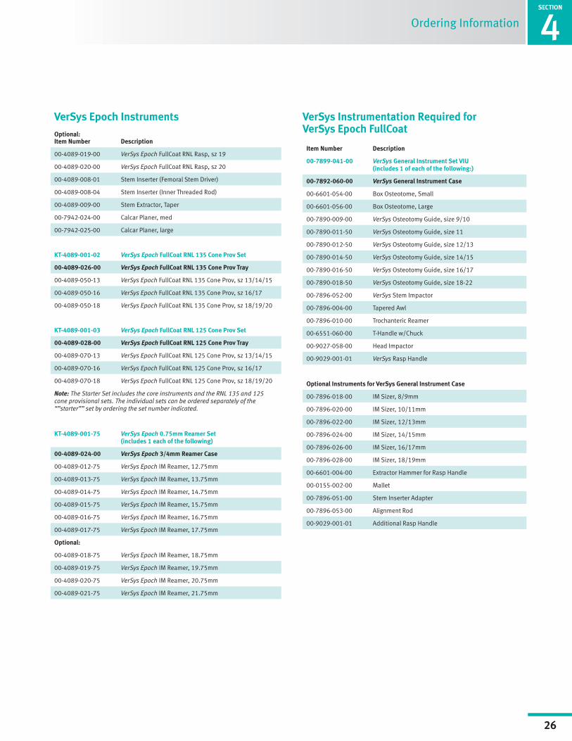
VerSys Epoch InstrumentsOptional:Item Number Description
00-4089-019-00 VerSys Epoch FullCoat RNL Rasp, sz 19
00-4089-020-00 VerSys Epoch FullCoat RNL Rasp, sz 20
00-4089-008-01 Stem Inserter (Femoral Stem Driver)
00-4089-008-04 Stem Inserter (Inner Threaded Rod)
00-4089-009-00 Stem Extractor, Taper
00-7942-024-00 Calcar Planer, med
00-7942-025-00 Calcar Planer, large
KT-4089-001-02 VerSys Epoch FullCoat RNL 135 Cone Prov Set
00-4089-026-00 VerSys Epoch FullCoat RNL 135 Cone Prov Tray
00-4089-050-13 VerSys Epoch FullCoat RNL 135 Cone Prov, sz 13/14/15
00-4089-050-16 VerSys Epoch FullCoat RNL 135 Cone Prov, sz 16/17
00-4089-050-18 VerSys Epoch FullCoat RNL 135 Cone Prov, sz 18/19/20
KT-4089-001-03 VerSys Epoch FullCoat RNL 125 Cone Prov Set
00-4089-028-00 VerSys Epoch FullCoat RNL 125 Cone Prov Tray
00-4089-070-13 VerSys Epoch FullCoat RNL 125 Cone Prov, sz 13/14/15
00-4089-070-16 VerSys Epoch FullCoat RNL 125 Cone Prov, sz 16/17
00-4089-070-18 VerSys Epoch FullCoat RNL 125 Cone Prov, sz 18/19/20
Note: The Starter Set includes the core instruments and the RNL 135 and 125 cone provisional sets. The individual sets can be ordered separately of the “”starter”” set by ordering the set number indicated.
KT-4089-001-75 VerSys Epoch 0.75mm Reamer Set (includes 1 each of the following)
00-4089-024-00 VerSys Epoch 3/4mm Reamer Case
00-4089-012-75 VerSys Epoch IM Reamer, 12.75mm
00-4089-013-75 VerSys Epoch IM Reamer, 13.75mm
00-4089-014-75 VerSys Epoch IM Reamer, 14.75mm
00-4089-015-75 VerSys Epoch IM Reamer, 15.75mm
00-4089-016-75 VerSys Epoch IM Reamer, 16.75mm
00-4089-017-75 VerSys Epoch IM Reamer, 17.75mm
Optional:
00-4089-018-75 VerSys Epoch IM Reamer, 18.75mm
00-4089-019-75 VerSys Epoch IM Reamer, 19.75mm
00-4089-020-75 VerSys Epoch IM Reamer, 20.75mm
00-4089-021-75 VerSys Epoch IM Reamer, 21.75mm
Item Number Description
00-7899-041-00 VerSys General Instrument Set VIU (includes 1 of each of the following:)
00-7892-060-00 VerSys General Instrument Case
00-6601-054-00 Box Osteotome, Small
00-6601-056-00 Box Osteotome, Large
00-7890-009-00 VerSys Osteotomy Guide, size 9/10
00-7890-011-50 VerSys Osteotomy Guide, size 11
00-7890-012-50 VerSys Osteotomy Guide, size 12/13
00-7890-014-50 VerSys Osteotomy Guide, size 14/15
00-7890-016-50 VerSys Osteotomy Guide, size 16/17
00-7890-018-50 VerSys Osteotomy Guide, size 18-22
00-7896-052-00 VerSys Stem Impactor
00-7896-004-00 Tapered Awl
00-7896-010-00 Trochanteric Reamer
00-6551-060-00 T-Handle w/Chuck
00-9027-058-00 Head Impactor
00-9029-001-01 VerSys Rasp Handle
Optional Instruments for VerSys General Instrument Case
00-7896-018-00 IM Sizer, 8/9mm
00-7896-020-00 IM Sizer, 10/11mm
00-7896-022-00 IM Sizer, 12/13mm
00-7896-024-00 IM Sizer, 14/15mm
00-7896-026-00 IM Sizer, 16/17mm
00-7896-028-00 IM Sizer, 18/19mm
00-6601-004-00 Extractor Hammer for Rasp Handle
00-0155-002-00 Mallet
00-7896-051-00 Stem Inserter Adapter
00-7896-053-00 Alignment Rod
00-9029-001-01 Additional Rasp Handle
VerSys Instrumentation Required for VerSys Epoch FullCoat
1SECTION
27
Surgical Technique Header4SECTION
27
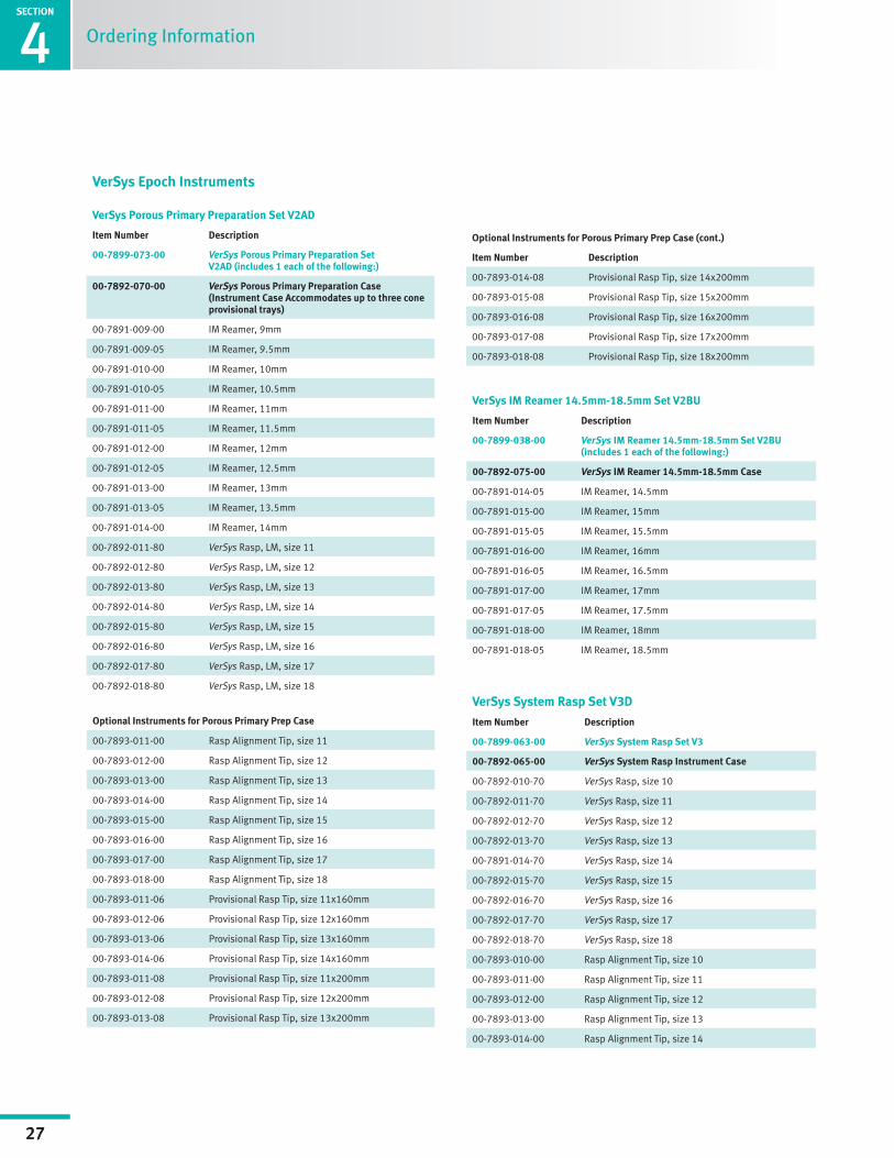
Optional Instruments for Porous Primary Prep Case
00-7893-011-00 Rasp Alignment Tip, size 11
00-7893-012-00 Rasp Alignment Tip, size 12
00-7893-013-00 Rasp Alignment Tip, size 13
00-7893-014-00 Rasp Alignment Tip, size 14
00-7893-015-00 Rasp Alignment Tip, size 15
00-7893-016-00 Rasp Alignment Tip, size 16
00-7893-017-00 Rasp Alignment Tip, size 17
00-7893-018-00 Rasp Alignment Tip, size 18
00-7893-011-06 Provisional Rasp Tip, size 11x160mm
00-7893-012-06 Provisional Rasp Tip, size 12x160mm
00-7893-013-06 Provisional Rasp Tip, size 13x160mm
00-7893-014-06 Provisional Rasp Tip, size 14x160mm
00-7893-011-08 Provisional Rasp Tip, size 11x200mm
00-7893-012-08 Provisional Rasp Tip, size 12x200mm
00-7893-013-08 Provisional Rasp Tip, size 13x200mm
VerSys IM Reamer 14.5mm-18.5mm Set V2BU
Item Number Description
00-7899-038-00 VerSys IM Reamer 14.5mm-18.5mm Set V2BU (includes 1 each of the following:)
00-7892-075-00 VerSys IM Reamer 14.5mm-18.5mm Case
00-7891-014-05 IM Reamer, 14.5mm
00-7891-015-00 IM Reamer, 15mm
00-7891-015-05 IM Reamer, 15.5mm
00-7891-016-00 IM Reamer, 16mm
00-7891-016-05 IM Reamer, 16.5mm
00-7891-017-00 IM Reamer, 17mm
00-7891-017-05 IM Reamer, 17.5mm
00-7891-018-00 IM Reamer, 18mm
00-7891-018-05 IM Reamer, 18.5mm
Ordering Information
VerSys Epoch Instruments
VerSys Porous Primary Preparation Set V2AD
Item Number Description
00-7899-073-00 VerSys Porous Primary Preparation Set V2AD (includes 1 each of the following:)
00-7892-070-00 VerSys Porous Primary Preparation Case (Instrument Case Accommodates up to three cone provisional trays)
00-7891-009-00 IM Reamer, 9mm
00-7891-009-05 IM Reamer, 9.5mm
00-7891-010-00 IM Reamer, 10mm
00-7891-010-05 IM Reamer, 10.5mm
00-7891-011-00 IM Reamer, 11mm
00-7891-011-05 IM Reamer, 11.5mm
00-7891-012-00 IM Reamer, 12mm
00-7891-012-05 IM Reamer, 12.5mm
00-7891-013-00 IM Reamer, 13mm
00-7891-013-05 IM Reamer, 13.5mm
00-7891-014-00 IM Reamer, 14mm
00-7892-011-80 VerSys Rasp, LM, size 11
00-7892-012-80 VerSys Rasp, LM, size 12
00-7892-013-80 VerSys Rasp, LM, size 13
00-7892-014-80 VerSys Rasp, LM, size 14
00-7892-015-80 VerSys Rasp, LM, size 15
00-7892-016-80 VerSys Rasp, LM, size 16
00-7892-017-80 VerSys Rasp, LM, size 17
00-7892-018-80 VerSys Rasp, LM, size 18
Optional Instruments for Porous Primary Prep Case (cont.)
Item Number Description
00-7893-014-08 Provisional Rasp Tip, size 14x200mm
00-7893-015-08 Provisional Rasp Tip, size 15x200mm
00-7893-016-08 Provisional Rasp Tip, size 16x200mm
00-7893-017-08 Provisional Rasp Tip, size 17x200mm
00-7893-018-08 Provisional Rasp Tip, size 18x200mm
VerSys System Rasp Set V3D
Item Number Description
00-7899-063-00 VerSys System Rasp Set V3
00-7892-065-00 VerSys System Rasp Instrument Case
00-7892-010-70 VerSys Rasp, size 10
00-7892-011-70 VerSys Rasp, size 11
00-7892-012-70 VerSys Rasp, size 12
00-7892-013-70 VerSys Rasp, size 13
00-7891-014-70 VerSys Rasp, size 14
00-7892-015-70 VerSys Rasp, size 15
00-7892-016-70 VerSys Rasp, size 16
00-7892-017-70 VerSys Rasp, size 17
00-7892-018-70 VerSys Rasp, size 18
00-7893-010-00 Rasp Alignment Tip, size 10
00-7893-011-00 Rasp Alignment Tip, size 11
00-7893-012-00 Rasp Alignment Tip, size 12
00-7893-013-00 Rasp Alignment Tip, size 13
00-7893-014-00 Rasp Alignment Tip, size 14
SECTION
1
28
Surgical Technique Header
SECTION
4
28
Ordering Information
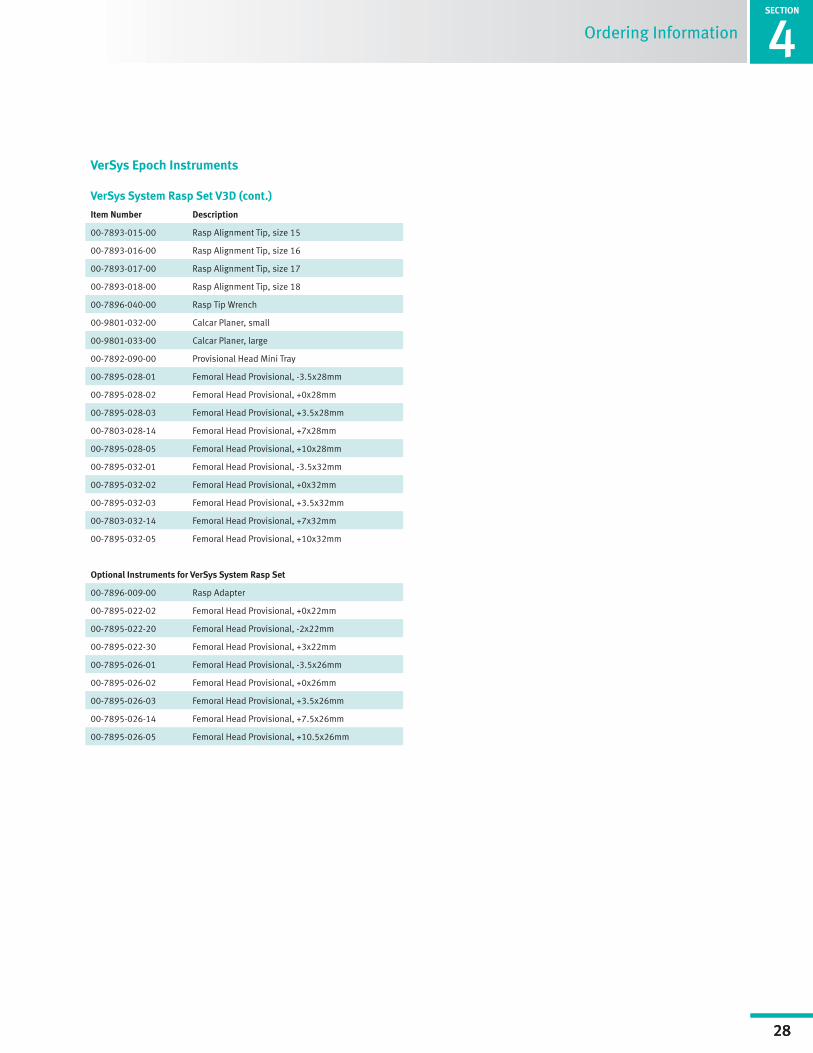
VerSys System Rasp Set V3D (cont.)
Item Number Description
00-7893-015-00 Rasp Alignment Tip, size 15
00-7893-016-00 Rasp Alignment Tip, size 16
00-7893-017-00 Rasp Alignment Tip, size 17
00-7893-018-00 Rasp Alignment Tip, size 18
00-7896-040-00 Rasp Tip Wrench
00-9801-032-00 Calcar Planer, small
00-9801-033-00 Calcar Planer, large
00-7892-090-00 Provisional Head Mini Tray
00-7895-028-01 Femoral Head Provisional, -3.5x28mm
00-7895-028-02 Femoral Head Provisional, +0x28mm
00-7895-028-03 Femoral Head Provisional, +3.5x28mm
00-7803-028-14 Femoral Head Provisional, +7x28mm
00-7895-028-05 Femoral Head Provisional, +10x28mm
00-7895-032-01 Femoral Head Provisional, -3.5x32mm
00-7895-032-02 Femoral Head Provisional, +0x32mm
00-7895-032-03 Femoral Head Provisional, +3.5x32mm
00-7803-032-14 Femoral Head Provisional, +7x32mm
00-7895-032-05 Femoral Head Provisional, +10x32mm
Optional Instruments for VerSys System Rasp Set
00-7896-009-00 Rasp Adapter
00-7895-022-02 Femoral Head Provisional, +0x22mm
00-7895-022-20 Femoral Head Provisional, -2x22mm
00-7895-022-30 Femoral Head Provisional, +3x22mm
00-7895-026-01 Femoral Head Provisional, -3.5x26mm
00-7895-026-02 Femoral Head Provisional, +0x26mm
00-7895-026-03 Femoral Head Provisional, +3.5x26mm
00-7895-026-14 Femoral Head Provisional, +7.5x26mm
00-7895-026-05 Femoral Head Provisional, +10.5x26mm
VerSys Epoch Instruments

1SECTION
29
Surgical Technique Header4SECTION
29
Ordering Information

SECTION
1
30
Surgical Technique Header
SECTION
4
30
Ordering Information