recycled tires as lightweight fill -...
TRANSCRIPT

Recycled Tires as Lightweight Fill
Bernie Mills, M.Sc.Eng., P.Eng. Senior Geotechnical Engineer,
Jacques Whitford Limited
and
Jared McGinn, P.Eng., P.Geo. Research Engineer, Design Branch
New Brunswick Department of Transportation
Paper prepared for presentation at the Recycled Materials and Recycling Processes for Sustainable Infrastructure Session of the 2008
Annual Conference of the Transportation Association of Canada
Toronto, Ontario

2
ABSTRACT Recycled Tires as Lightweight Fill The New Brunswick Department of Transportation (NBDOT) is incorporating shredded tires into the reconstruction of a highway embankment. These shredded tires (referred to as Tire Derived Aggregate or TDA) have a much lower unit weight than conventional earth fills and provide an economical solution to reducing the load of an embankment constructed over soft foundation soils. Prior to choosing the TDA redesign, NBDOT considered stabilization options including; replacing soft soils with granular fill, using stone columns, and reducing loads with geofoam as lightweight fill. The original 14 metre high and 140 metre long embankment section failed during construction in 2006. To significantly reduce the load and keep the original design height of the embankment, 1.6 million scrap tires will be recycled into TDA lightweight fill. TDA will be placed in two separated 3 metre thick layers within soil fill to form the lightweight embankment. The geotechnical, economic and environmental benefits of selecting the TDA design are discussed in this paper. Also, design precautions, TDA construction and materials handling for Stage 1 of the TDA embankment are presented. The final stage of the construction will be completed in the summer of 2008.
3
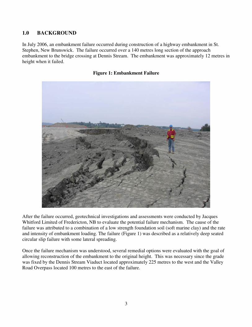
1.0 BACKGROUND In July 2006, an embankment failure occurred during construction of a highway embankment in St. Stephen, New Brunswick. The failure occurred over a 140 metres long section of the approach embankment to the bridge crossing at Dennis Stream. The embankment was approximately 12 metres in height when it failed.
Figure 1: Embankment Failure
After the failure occurred, geotechnical investigations and assessments were conducted by Jacques Whitford Limited of Fredericton, NB to evaluate the potential failure mechanism. The cause of the failure was attributed to a combination of a low strength foundation soil (soft marine clay) and the rate and intensity of embankment loading. The failure (Figure 1) was described as a relatively deep seated circular slip failure with some lateral spreading. Once the failure mechanism was understood, several remedial options were evaluated with the goal of allowing reconstruction of the embankment to the original height. This was necessary since the grade was fixed by the Dennis Stream Viaduct located approximately 225 metres to the west and the Valley Road Overpass located 100 metres to the east of the failure.

4
Based on the failure mechanism, several remedial options were reviewed using one of two fundamental repair strategies as follows:
1. Strengthen the foundation to allow the embankment to be reconstructed using conventional soil: • Removal and replacement of foundation soils (remove soft clay and replace with
imported granular fill), or • Stone Columns, or • Stage Construction and pre-fabricated vertical wick drains
2. Reduce the Embankment Load on existing soft foundation soils using lightweight fill:
• Geofoam in combination with shredded tires, or • Shredded tire fill (referred to as Tire Derived Aggregate or TDA)
After reviewing various repair options, reconstruction of the embankment using TDA lightweight fill combined with stage construction and pre-fabricated wick drains was selected. The benefits of TDA and the reasons for selecting this option are described in more detail below. In general, using TDA as a lightweight fill reduces the load on the soft foundation soils while prefabricated vertical drains in the underlying clay accelerates consolidation within the time allowed for stage construction. 2.0 BENEFITS OF TDA AS LIGHTWEIGHT FILL 2.1 TDA Benefits TDA offered many benefits to the project mainly its light weight, (approximately 1/3 the unit weight of traditional soil), and its proven track record in the civil engineering community in the United States. TDA is locally available in central NB making it the most economically feasible option. It was estimated that using TDA will save NBDOT 30% of the total cost compared to the next feasible option (Stone Columns). The sustainability benefits in using TDA was also important since this project will put approximately 1.6 million scrap tires to good use, which equates to approximately two years of discarded tires that are generated in the province of New Brunswick. 2.2 Tire Stewardship Board and Tire Recycling
The TDA option was viable because of two factors which favored the selection of TDA. Firstly, the tire recycling facility is within 160 km of the embankment site. Transportation cost of TDA would have been prohibitive if the facility was located at a greater distance or if there were multiple, smaller tire recycling centers. Secondly, TDA not only qualified as a recycled product, but the road construction project was seen by the New Brunswick Tire Stewardship Board (NBTSB) as a direct benefit to tire consumers. This combination of factors enabled the tire recycling facility to collect a portion of the environmental fee paid by tire consumers. For TDA delivered to the embankment reconstruction site, the tire recycling facility received 97% of the cost in the form of subsidies from the NBTSB and the remaining portion from NBDOT. This arrangement was not only profitable for the recycling facility, but was also a much lower cost for NBDOT when compared to other lightweight fill options and fulfilled the stewardship principle of reusing the scrap tires in an environmentally friendly manner.

5
2.3 Cost Comparison of Embankment Reconstruction Options Table 1 below provides a comparison of benefits and disadvantages of the various options that were considered at the conceptual review stage of the project. Table 1: Benefits and Disadvantages of Various Repair Options (2006/2007)
Repair Option Benefits Disadvantages
1. Removal of Soft Soils and Replacement with Imported Granular Fill
- Conventional construction techniques
- Very low risk of future embankment failure
- Minimizes secondary settlement - Eliminates the importance of soil
profile and soil parameter assumptions
- No instrumentation required
- Very deep excavation would be a challenge in the soft clays and large excavation footprint would require gaining access to private land to the south, which was unfavorable. - Very large quantity of soft clay soils to dispose of off-site would be a challenge. - Risk of undermining adjacent highway embankment - Estimated cost is three times the estimated cost of the TDA option
2. Stone Columns (Installed by a Specialty
Contractor)
- Will allow embankment to be constructed relatively quickly after treatment using conventional soils. - Will allow for the original designed geometry of the embankment
- Large quantity of soft clay to be disposed of off-site. - Specialty contractor had some concerns that the clay soils may be too soft in areas and would not provide the necessary confining pressure for stone columns. - Estimated cost is 1.4 times the estimated cost of the TDA option
3. Geofoam + TDA
- Can leave soft foundation soils in place - Very light weight and easy to construct - No wick drains required
- Geofoam on its own was considerably more expensive than Geofoam+TDA. - Estimated cost is 1.7 times the estimated cost of the TDA option
4. TDA
- Can leave soft foundation soils in place - Limits extent of excavation required - Most economical option. - Good track record and many successful cases reported in the literature. - ASTM standards available for TDA use in civil engineering applications. - TDA locally available in NB
- Wick drains required in combination with TDA - Staged construction necessary - Instrumentation required to monitor foundation soil’s response to loading.

6
3.0 TIRE DERIVED AGGREGATE (TDA) – LITERATURE REVIEW 3.1 Material Properties of TDA Tire Derived Aggregate (TDA) is created from the shredding of scrap tires into sizes ranging from 50 millimetres to 300 millimetres. TDA is lightweight, free draining, produces low earth pressures, absorbs vibrations, are compressible, and have a thermal resistivity that is about seven times higher than conventional soil (Humphrey et al., 2000). Because of their special properties, TDA is increasingly being used as lightweight fill for embankment construction on weak, compressible foundation soils. Other applications for TDA include lightweight fill behind retaining walls and bridge abutments, thermal insulation to limit frost penetration below roads, drainage layers for roads, compressible inclusions behind integral abutments, vibration damping layers for rail lines, and landfill applications (Humphrey, 2003). TDA has also been mixed with soil to produce high strength composite materials. 3.2 TDA History in United States In 1996, an estimated ten million scrap tires were used for civil engineering applications (STMC, 1997). By 2004, this figure had grown to sixty million tires, or twenty percent of the scrap tires that were generated in the United States in that year (Recycling Research Institute, 2005). As reported by Humphrey (Humphrey et al, 2000), the reason for this growth is simple – TDA has the properties that civil engineers need and using TDA can significantly reduce construction costs.
A significant setback occurred in the industry in 1995 and early 1996 when three thick TDA fills (greater than 7.9 metres thick) experienced a serious self-heating reaction within six months of completion. The lessons learned from these projects were condensed into design guidelines developed by the Ad Hoc Civil Engineering Committee (1997), a partnership of government and industry. The guidelines were subsequently published by ASTM (1998). Since 1995/1996, there have been over seventy TDA fills constructed in the US with a thickness less than three metres with no evidence of a deleterious heating reaction. 3.3 Design Considerations using TDA When designing using TDA, the following parameters are important (from Humphrey et al, 2000, and ASTMD6270):
• Final In-Place Unit Weight of the TDA is an important parameter to be estimated during design. Evaluation of this parameter must consider compression of the TDA under its own self weight and the weight of the overlying soil. There are methods and information available in the literature on estimating the final in-place unit weight of TDA.
• Calculation of Overbuild. TDA experiences immediate compression under an applied load. The top elevation of the TDA layer should be overbuilt to compensate for this compression to obtain the target compressed thickness of TDA. Design charts are available in the literature for assisting in designing for TDA overbuild.

7
• Time Dependent Settlement: For design, it is recommended to allow sufficient time for most of the time dependent settlement of the TDA to occur prior to paving. Time dependent settlement is less of a concern when the ends of the TDA are tapered providing a transition from the full to zero thickness.
• Guidelines to Limit Heating Reaction: A summary of the guidelines to limit the self heating
reaction in TDA fills less than 3 metres thick are as follows:
� TDA shall be free of contaminants such as gasoline, diesel, oil, grease, etc.
� TDA shall not contain remnants of tires that have been subjected to a fire.
� TDA shall be free of fragments of wood, wood chips, and other fibrous organic matter.
� Gradation of TDA (Class II TDA) o Maximum of 50 % (by weight) passing 75 mm sieve, o Maximum of 25 % (by weight) passing 37.5 mm sieve o Maximum of 1 % (by weight) passing the 4.75 mm sieve
� The TDA shall have less than 1 % (by weight) of metal fragments, which are not at least
partially encased in rubber. Metal fragments that are partially encased in rubber shall protrude no more than 25 mm from the cut edge on 75 % of the pieces and no more than 50 mm on 90 % of the pieces.
� MMiinniimmiizzee iinnffiillttrraattiioonn ooff aaiirr aanndd wwaatteerr iinnttoo tthhee TTDDAA.. TThhiiss iiss ttyyppiiccaallllyy aaccccoommpplliisshheedd uussiinngg aa llaayyeerr ooff llooww permeable soil (with a minimum 30 % fines) surrounding the TDA.
� TDA shall not be in direct contact with soil containing organic matter, such as topsoil.
� The TDA should be separated from the surrounding soil using a geotextile.
� Use of drainage features located at the bottom of the fill that could provide free access to
air should be avoided. ASTMD6270-98 provides comments that if drains are to be used by the designers that a well graded material be used to minimize access to air.
� 3 metres maximum TDA layer thickness (after compression).
3.4 Water Quality Effects using TDA
� Several studies have shown that TDA can be used in most applications with negligible
effects on groundwater quality (Humphrey et al, 2000).
� As reported in ASTM D6270, according to the Toxicity Characteristics Leaching Procedure (TCLP)(USEPA Method 1311), for all regulated metals and organics, the

8
results for TDA are well below the TCLP regulatory limits, therefore, TDA in the US is not classified as a hazardous waste.
� In addition to TCLP tests, laboratory leaching studies have been performed and have shown that metals are leached most readily at low pH and that organics are leached most readily at high pH, thus it is preferable to use TDA in near neutral environments.
� Field studies of TDA fills located above the groundwater table show that TDA tend to
leach manganese, and under some circumstances iron at levels above their secondary drinking water standards. Since, secondary standards are based on aesthetic factors such as colour, odor, and taste, rather than health concerns, release of manganese and iron from TDA is not a significant concern. Release of organics from TDA above the groundwater table generally is below test method detection limits; thus, release of organics from TDA is not a significant concern when placed above the groundwater table. ASTM D6270 recommends procedures to consider for TDA applications below the groundwater table.
4.0 CASE HISTORY: ST. STEPHEN EMBANKMENT RECONSTRUCTION PROJECT The embankment reconstruction is located on the proposed four lane highway section of Route 1 between the existing Route 750 and Dennis Stream, in St.Stephen, New Brunswick. A brief discussion of the overall design of the project is provided below. Supply of TDA and construction of Stage 1 is also discussed below. Stage 1 was completed in the fall 2007, which consisted of the first layer of TDA only. Stage 2 of the project is proposed to be completed over the summer and fall 2008. 4.1 Design
To remediate the failed 140 metre long section of embankment to the original design height of 14 metres, lightweight fill using TDA was selected. The design consisted of a combination of TDA to reduce the embankment load, pre-fabricated vertical drains to accelerate consolidation of the underlying clay, and a staged construction approach. The design also considered the use of geotechnical instrumentation to monitor the behavior of the embankment and underlying foundation soils during the embankment reconstruction process. Slope stability modeling was conducted to optimize the section and profiles required to provide adequate stability using the TDA. A typical design cross-section is provided on Figure 2.

9
Figure 2: Design Cross-Section (Typical)
Some of the design elements are described as follows:
• The design included pre-fabricated vertical drains (PVD) at 1.5 metres spacing between drains.
• A 0.5 metres thick sand drain located immediately above the PVD’s to allow drainage to be directed to the ditch at the south end.
• The embankment was designed with two – 3 metres thick layers of TDA (after compression). A total TDA volume of 20,000 m3 (16,000 tonnes) was estimated.
• The TDA type, Class II Fill (coarse tire shreds with a maximum size of 300 mm) was specified
according to ASTM D6920-98 (2004). The TDA specifications for the project included guidelines according to ASTM for limiting the self heating reaction.
• The final in-place unit weight of the TDA was predicted to be 800 kg/m3 or 7.8 kN/m3.
• Overbuild was considered in the design thickness of the two layers so that the maximum thickness
of the TDA after compression would be approximately 3 metres.
• The TDA profile and section was tapered wherever possible by providing a transition from the full to zero thickness.
• The TDA layers were designed to be fully wrapped with woven geotextle (NBDOT Type W3) to
act as a separator.

10
• A minimum 1 metre of low permeability soil cover (minimum 30 percent fines by weight) is provided, surrounding the TDA. This element is to prevent air and water from gaining access to the TDA.
• Both TDA layers were designed with drains to allow any water to drain out of the TDA fill. The drains were designed using well graded granular fills to minimize air infiltration into the TDA.
• The design considered a surcharge element at the end of the staged construction to accelerate the
final consolidation settlement.
• The final driving surface will have approximately 2.2 metres of separation between it and top of the TDA.
• The design considered the following geotechnical instrumentation. Duplicate instrumentation
was used for redundancy. � Vibrating wire (VW) piezometres to monitor pore pressure in the underlying foundation
clay soils. � Vibrating wire earth pressure cells to monitor total stress from the applied loads. � Vibrating wire settlement cells to monitor vertical displacement with time. � Slope inclinometers to monitor lateral movement in the embankment and underlying
foundation clay soils. � Vibrating wire temperature cells for monitoring temperature in the TDA.
4.2 TDA Supply There were two fundamental elements concerning supply of TDA for this project: Quality and Quantity. Project specifications for TDA quality were developed using ASTMD6270 Standards (Guidelines for limiting the self heating reaction). TDA quantity is the other important element to supply, which became an issue for Stage 1 construction as described in more detail below. The design called for 16,000 tonnes of TDA for the project, representing approximately 1.6 million tires. Some of the highlights concerning supply for this project are provided below:
• The existing stockpiled materials (Figure 3) consisted of shred not originally intended for the TDA application. However, the TDA materials in their existing condition (for the most part) met the project specifications, with specific zones and stockpiles of materials being slightly too dirty or steel protrusion quantity being too high. With some hard work on the part of the supplier using sorting, screening, and reprocessing techniques, the supplier was able to develop the existing stockpiled materials to meet the project specifications.

11
Figure 3: TDA from Existing Stockpiles
• TDA quality was enforced during the Stage 1 supply process by having dedicated testing personnel at the tire recycling facility during the loading, sorting, screening, and shredding phases.
• The quantity of TDA from existing stockpiles was originally underestimated, and as such Stage 1 (first layer of TDA only) was completed in the fall 2007. Completion of the project (Stage 2) is proposed for summer and fall 2008.
• The majority of the tires that were delivered to the recycling facility for Stage 1 were from New Brunswick. In order to accumulate enough TDA for this project, scrap tires were also collected from Nova Scotia and Prince Edward Island.
4.3 Transportation and Construction using TDA
Construction started in early June 2007 starting with site grading, followed by placement of the sand drainage layer, and installation of the PVD’s. Transportation of TDA from the tire recycling facility to the site in St. Stephen occurred over a 1.5 month period starting about the middle of August, 2007. Some of the highlights concerning TDA transportation and construction for this project are provided below:

12
• The TDA was transported from the tire recycling facility using “floating” floor trailers. This allowed approximately 35 m3 of TDA to be transported per trailer.
• Initially, the TDA was temporarily stockpiled at the site very close to its final location. This allowed the transportation of the TDA to take place before the working area was ready for placement.
• The subgrade was prepared followed by the placement of a woven geotextile and placement and compaction of the TDA in lifts. The TDA was placed in 400 mm (loose) lifts using a track mounted bulldozer (Figure 4). Each lift of TDA was then compacted with a vibratory smooth drum roller with a minimum of 6 passes.
Figure 4: Spreading TDA with a bulldozer
• A layer of low permeable soil cover was placed and compacted in lifts on the top and sides of the first layer of TDA.
• The geotechnical instrumentation was monitored throughout Stage 1 construction. Vibrating wire earth pressure cells, used to measure total stress below the embankment, showed that the unit weight of the TDA to be 7.9 kN/m3 (805 kg/m3), which is very close to the predicted value. Also, the vibrating wire temperature cells, used to measure the internal temperature of TDA, showed the temperature of the TDA to be 26 degrees Celsius at the time of placement and within 3 months, the temperature had dropped to 17 degrees Celsius. Therefore, the measures that were

13
taken to limit the internal heating (ASTM D6270) were effective. Figure 5 below shows the locations of the VW Earth Pressure Cells and the VW Temperature Cells.
• Stage 1 of the project (first lift of TDA and a layer of low permeable soil) was completed in the fall of 2007. Figure 5 below provides the Stage 1 As-built cross section.
• Stage 2 will consist of completing the project up to the top of the design elevation as illustrated in Figure 2 Design Cross-Section.
Figure 5: Stage 1 As-Built Cross-Section (Typical)
5.0 CONCLUSIONS
• TDA is a beneficial material that can be used as lightweight fill for highway embankment projects constructed on weak clays.
• For the case study described in this paper, the low unit weight, proven track record, and the local availability (which made this option economically feasible), resulted in the TDA option being selected.
• Use of TDA in this application will put approximately 1.6 million scrap tires to good use. This quantity of tire is equivalent to approximately 2 years of scrap tires that are expected to be generated in the province of New Brunswick.
• Collecting, delivering, and processing scrap tires into TDA are arduous tasks. Construction schedules should allow for and accommodate delays in the delivery of TDA from recycling facilities.

14
• Construction using TDA for Stage 1 went according to plan. The TDA was relatively easy to load, transport, place and compact using traditional earthmoving equipment. The use of trailers equipped with “floating” floors was very advantageous.
• Results of the geotechnical instrumentation for Stage 1 have shown that the in-place TDA is lightweight (TDA Unit Weight = 7.9 kN/m3) with internal TDA temperatures within acceptable and predicted limits.
• When compared to the next feasible option, the TDA option chosen is estimated to result in a savings, to the Department of Transportation, of about thirty percent 30% (approximately five hundred thousand dollars for this project)
6.0 ACKNOWLEDGEMENTS
The authors would like to acknowledge Dr. Dana Humphrey for providing peer review for the project during the design and preliminary stages of construction. 7.0 REFERENCES
1. Humphrey, D.N., Whetten, N., Waever, J. & Recker, K. 2000, Tire Shreds as Lightweight
Fill for Construction on Weak Marine Clay, Proceedings of the International Symposium on Coastal Geotechncal Engineering Practice, p 611-618. Balkema: Rotterdam.
2. STMC 1997. Scrap Tire Use/Disposal Study – 1996 Update. Washington, DC: Scap Tire Management Council.
3. Recycling Research Institute 2005. Scrap Tires and Rubber Users Director 14th Edition, Leesburgh, Virginia: Recycling Research Institute.
4. ASTM1998 (Updated in 2004). Standard Practice for Use of Scrap Tires in Civil Engineering Applications. ASTMD6270-98. W. Conshohocken, Pennsylvania; Am. Soc. Testing & Mat.