transceiver design
TRANSCRIPT

TRANSCEIVER DESIGN
BY
SATYANARAYANA
CHETAN SONI
HENDRY NEWMAN
10/3/2015 Transceiver Design 1

Link Budget
• Link budget determines the necessary parameters for successfultransmission of a signal from a transmitter to a receiver.
• The term link refers to linking or connecting the transmitter to the receiver.
• The term budget refers to the allocation of RF power, gains, and losses, and tracks both
the signal and the noise levels throughout the entire system.
10/3/2015 Transceiver Design 2
PARAMETERS:
• Required power output level from transmitting antenna and receiver sensitivity
• Gains and losses in system and link
• SNR for reliable detection
• Bit Error Rate.

Link Power Budget
10/3/2015 Transceiver Design 3
Understanding Power in dB
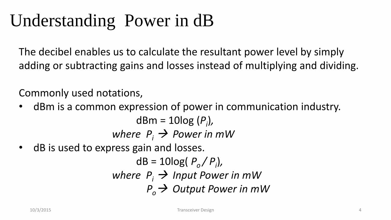
The decibel enables us to calculate the resultant power level by simply adding or subtracting gains and losses instead of multiplying and dividing.
Commonly used notations,• dBm is a common expression of power in communication industry.
dBm = 10log (Pi),where Pi Power in mW
• dB is used to express gain and losses.dB = 10log( Po / Pi),
where Pi Input Power in mWPo Output Power in mW
10/3/2015 Transceiver Design 4

Transmitter
Power from the transmitter: Pt
The power from the transmitter (Pt) is the amount of power output of the final stage of the power amplifier.
Pt(in dBm) = PdBm = 10 log10 PmW
10/3/2015 Transceiver Design 5

Transmitter Component Losses: Lt_comp
• Transmitter consist of different components like circulator, switchers etc., the losses
connected with these components are Transmitter components losses.
Lt_comp = Losses in components like circulator, switchers
• These losses directly affect the link budget on a one-for-one basis.
• Each dB of loss in this path will either reduce the minimum detectable signal
(MDS) by 1 dB or the transmitter gain will have to transmit 1 dB more power.
10/3/2015 Transceiver Design 6

Transmitter Line Losses from the Power Amplifier to
Antenna: Ltll
• Most transmitters are located at a distance from the antenna, the cable or waveguide
connecting the transmitter to the antenna contains losses.
Ltll = Losses in coaxial or waveguide line
• This loss also directly affect the link budget on a one-for-one basis.
How to avoid this loss????
• Using larger diameter cables or higher quality cables can reduce the loss, which
is a trade-off with cost.
• Locate the transmitter power amplifier as close to the antenna
as possible, so that length of the cable is reduced.10/3/2015 Transceiver Design 7

Transmitter Antenna Gain : Gt
• Most antennas experience gain because they tend to focus energy in specified
directions as compared to an ideal isotropic antenna which radiates in all directions.
Example 1: A typical vertical dipole antenna has 2.1dBi of gain.
10/3/2015 Transceiver Design 8

Example 2: Parabolic dish antenna is commonly used in higher frequencies
Gain of Parabolic antenna: Gt = 10 log[ n( πD/λ)2 ]
Note:• Antenna gain increases both with increasing diameter and frequency.
10/3/2015 Transceiver Design 9

Transmitter Antenna Losses : Lta
• Radome Losses: Ltr
The radome is the covering over the antenna that protects the antenna from
the outside elements.
• Polarization Mismatch Loss: Ltpol
o A mismatch loss is due to the polarization of the transmitter antenna
being spatially off with respect to the receiver antenna.
o The amount of loss is equal to the angle difference between them.
Example:
If the angle difference between the polarization of the transmitter and receiver is 20
degrees.
then, Ltpol = 20 log( cos θ) = 20 log(cos 20) = .54 dB
10/3/2015 Transceiver Design 10

• Focussing Losses: Ltfoc
This is a loss caused by imperfections in the shape of the antenna.
• Mispointed Loss: Ltpoint
This is caused by transmitting and receiving directional antennas that are not exactly lined up.
• Conscan Crossover Loss: Ltcon
Conscan means that the antenna system is either electrically or
mechanically scanned in a conical fashion, or in a cone-shaped pattern.
This loss is only present if the antenna is scanned in a circular search
pattern such as in Radar.
The total transmitter antenna loss in the link budget is
Lta = Ltr + Ltpol + Ltfoc + Ltpoint + Ltcon
10/3/2015 Transceiver Design 11

Transmitted EIRP :
EIRP is the amount of power from a single point radiator that is required to equal the
amount of power that is transmitted by the power amplifier, losses, and directivity of the
antenna (antenna gain) in the direction of the receiver.
where:
Pt = transmitter power,
Ltcomp = switchers, circulators, antenna connections,
Ltll = coaxial or waveguide line losses (in dB),
Gt = transmitter antenna gain,
Lta = total transmitter antenna losses.
EIRP = Pt + Ltcomp + Ltll + Gt + Lta
10/3/2015 Transceiver Design 12

10/3/2015 Transceiver Design 13
Recalling previous class discussion -

10/3/2015 Transceiver Design 14
Channel :
The channel is the path of the RF signal that is transmitted from the
transmitter antenna to the receiver antenna
Channel Link Budget :

10/3/2015 Transceiver Design 15
Free Space Attenuation:
This loss is due to dispersion, the ”spreading out” of the beam of radio energy as it
propagates through space.
The main contributor to channel loss is free-space attenuation.
Figure from http://en.wikipedia.org/wiki/Inverse_square
Afs = 20log[4Rf/c]
where:Afs = free-space lossR = slant range (same units as ),f = frequency of operation,c = speed of light, 300 × 106 m/sec, R is in meters.

10/3/2015 Transceiver Design 16
• Multipath losses
Lmulti = losses due to multipath cancellation of the direct path signal (in dB).

10/3/2015 Transceiver Design 17
Receiver-

10/3/2015 Transceiver Design 18
• Radome Losses: Lrr
The radome is the covering over the antenna that protects the antenna
from the outside elements.
• Polarization Mismatch Loss: Lrpol
o A mismatch loss is due to the polarization of the transmitter antenna
being spatially off with respect to the receiver antenna.
o In general, for two linearly polarized antennas that are rotated from
each other by an angle , the power loss due to this polarization
mismatch will be described by the Polarization Loss Factor (PLF)
• Focusing Losses: Lrfoc
This is a loss caused by imperfections in the shape of the antenna.
Receiver Antenna Losses : Lra

• Mispointed Loss: Lrpoint
This is caused by transmitting and receiving directional antennas that are not exactly lined up.
• Conscan Crossover Loss: Lrcon
Conscan means that the antenna system is either electrically or
mechanically scanned in a conical fashion, or in a cone-shaped pattern.
This loss is only present if the antenna is scanned in a circular search
pattern such as in Radar.
The total Receiver antenna loss in the link budget is
Lra = Lrr + Lrpol + Lrfoc + Lrpoint + Lrcon
10/3/2015 Transceiver Design 19

10/3/2015 Transceiver Design 20
Receiver Antenna Gain
• The receiver antenna is not required to have the same antenna as the
transmitter.
• The gain of the antenna is a direct gain in the link budget a 1 dB gain equals a
1 dB improvement in the link analysis.

10/3/2015 Transceiver Design 21
Receiver Line Losses from the Antenna to the LNA
Lrll = coaxial or waveguide line losses (in dB).
• cable length should be kept as short as possible, with the option of
putting the LNA with the antenna assembly.
Receiver Component Losses- Any components between the antenna and LNA will
reduce the SNR of the system.
Lrcomp = switches, circulators, limiters, and filters.
• These losses directly affect the link budget on a one-for-one basis.

10/3/2015 Transceiver Design 22
Received Signal Power at the Output to the LNA
• The received signal level Ps (in dBm)
Ps = EIRP + Afs + Lp + Lmulti + Lra + Gr + Lrll + Lrcomp + GLNA,
o This equation makes the assumption that all the losses are negative.
o Gr , GLNA, and EIRP are positive.
• The noise out of the LNA (in dBm)-
NLNA = kTB dBm + F dB + GLNA dB.
10/3/2015 Transceiver Design 23
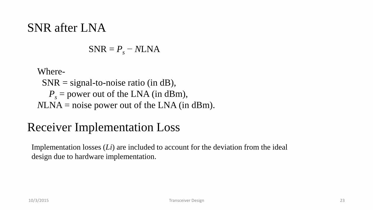
SNR after LNA
SNR = Ps − NLNA
Where-
SNR = signal-to-noise ratio (in dB),
Ps = power out of the LNA (in dBm),
NLNA = noise power out of the LNA (in dBm).
Receiver Implementation Loss
Implementation losses (Li) are included to account for the deviation from the ideal
design due to hardware implementation.

10/3/2015 Transceiver Design 24
Received Power for Establishing the SNR of System
The detected power Pd (in dB) that is used to calculate the final
SNR used in the analysis is
Pd = Ps + Li + Greceiver
where:
Ps = power to the LNA (in dBm),
Li = implementation losses,
Greceiver = receiver gain.

10/3/2015 Transceiver Design 25
NUMERICAL QUESTIONS
1. Show that a specification of 0 dBm ± 2 dBm is an impossible statement
and write a correct statement for it.
2.What is the diameter of a parabolic antenna operating at 5 GHz, at an
efficiency of 0.5 and a gain of 30 dBi?
3. What is the free-space attenuation for the system in Problem 2 with a
range of 10 nautical miles?
4. What is the noise level out of the LNA given that the bandwidth is
10 MHz and the LNA NF is 3 dB with To = Ts at room temperature?
5. What is the NF of the receiver, given that the LNA has an NF of 3 dB,
a gain of 10 dB, a second amplifier after the LNA with a gain of 20 dB
and an NF of 10 dB, and there is a loss of 5 dB between the amplifiers?
10/3/2015 Transceiver Design 26
References:
1. Scott R. Bullock, “Transceiver and Systems Design for Digital Communications,”
3rd Edition, Scitech Publishing.
2. Tranzeo link budget analysis whitepaper,
http://www.tranzeo.com/allowed/Tranzeo_Link_Budget_Whitepaper.pdf