transceiver design for wireless energy harvesting …transceiver design for wireless energy...
TRANSCRIPT

Transceiver Design for Wireless Energy Harvesting
Cooperative Networks
Shiyang Hu
Lancaster University
School of Computing and Communications,
Lancaster, UK.
A thesis submitted for the degree of
Doctor of Philosophy
2016

I
To my beloved ones, for their support and encouragement.

II
Acknowledgements
In my Ph.D. study at the Lancaster University, I was lucky to have the great
opportunity to work with my supervisor Prof. Zhiguo Ding who introduced me to
research the wireless energy harvesting. Without any doubt, I could not achieve my
research project without his help. I want to express my sincere gratitude for his
valuable guidance and continuous support.
I want to direct my special gratitude to my second supervisor Prof. Qiang Ni for
his suggestions in my Ph.D. study. His broad knowledge helped me to overcome many
difficulties.
My gratitude is also extended to the School of Computing and Communications
for giving me the opportunity to have this memorable learning experience.
Finally, I would like to express my sincere gratitude to my parents who have
always supported me. They were always there when I needed them. My parents
deserve far more credit than I can give.

III
Declaration
I declare that this thesis is my work, and it has not been previously submitted, either
by me or by anyone else, for a degree or diploma at any educational institute, school
or university. To the best of my knowledge, this thesis does not contain any previously
published work, except where another person’s work used has been cited and included
in the list of reference.

IV
Abstract
In this thesis, the RF energy harvesting technique is studied in the cooperative
wireless network, and different optimization studies are investigated. First, an
energy-efficient optimization is considered in the cooperative system with the time
switching relaying and power splitting relaying protocols. Then, a security issue in the
cooperative network with energy harvesting is proposed, in which the optimization
problem is designed to maximize the secrecy rate. We also consider the application of
energy harvesting in the full-duplex relaying network with a self-energy recycling
protocol. Finally, the energy harvesting is studied in the full-duplex cooperative
cognitive radio network. The system performance of all studies is verified in the thesis
with MATLAB simulation results.

V
Contents
List of Figures x
List of Tables xiii
List of Acronyms xiv
List of Symbols xvi
Contents
1. Introduction ................................................................................................................ 1
1.1 An Overview of Wireless Energy Harvesting ...................................................... 1
1.2 Contributions ........................................................................................................ 5
1.3 Publications Arising From This Research ............................................................ 6
1.4 Outline of the Thesis ............................................................................................ 8
2. Background ................................................................................................................ 9
2.1 Architecture of Wireless Energy Harvesting Network ......................................... 9
2.2 Wireless Energy Harvesting Technique ............................................................. 12
2.3 Applications of Wireless Energy Harvesting ..................................................... 15

VI
2.4 Wireless Information and Power Transfer ......................................................... 16
2.4.1 Separated Structure ..................................................................................... 18
2.4.2 Time Switching and Power Splitting .......................................................... 20
2.4.3 Integrated Structure ..................................................................................... 23
2.5 Literature Review for SWIPT ............................................................................ 25
2.5.1 Energy Harvesting Protocols ...................................................................... 25
2.5.2 Energy Harvesting for Multi-Antenna Network ......................................... 30
2.5.3 Cooperative Relaying Network ................................................................... 38
2.6 Chapter Summary .............................................................................................. 45
3. Energy-Efficient Optimization in Cooperative Networks with Wireless Information
and Power Transfer ...................................................................................................... 46
3.1 Introduction ........................................................................................................ 46
3.2 System Model .................................................................................................... 47
3.3 Energy-Efficient Optimization based on Time Switching Relaying Protocol ... 49
3.3.1 Time Switching Relaying Protocol ............................................................. 49
3.3.2 System Transmission Model ....................................................................... 50

VII
3.3.3 Problem Formulation .................................................................................. 53
3.4 Energy-Efficient Optimization based on Power Splitting Relaying Protocol .... 55
3.4.1 Power Splitting Relaying Protocol .............................................................. 55
3.4.2 System Transmission Model ....................................................................... 56
3.4.3 Problem Formulation .................................................................................. 58
3.5 Solution of Formulated Optimization Problems ................................................ 59
3.6 Numerical Results .............................................................................................. 66
3.7 Chapter Summary .............................................................................................. 73
4. Secure Communication in Cooperative Networks with Wireless Information and
Power Transfer ............................................................................................................. 74
4.1 Introduction ........................................................................................................ 74
4.2 System Model .................................................................................................... 76
4.3 Secrecy Rate Maximization based on Power Splitting Relaying Protocol ........ 78
4.3.1 System Transmission Model and Problem Statement ................................. 78
4.3.2 The Optimal Solution .................................................................................. 83
4.4 Secrecy Rate Maximization based on Time Switching Relaying Protocol ........ 89

VIII
4.4.1 System Transmission Model and Problem Statement ................................. 89
4.4.2. The Optimal Solution ................................................................................. 92
4.5 Numerical Results .............................................................................................. 95
4.6 Chapter Summary ............................................................................................ 100
5. Beamforming Optimization in Energy Harvesting Cooperative Full-Duplex
Networks with Self-Energy Recycling Protocol ........................................................ 101
5.1 Introduction ...................................................................................................... 101
5.2 System Model .................................................................................................. 103
5.3 Beamforming with Self-Energy Recycling Relay ........................................... 105
5.3.1 Relay Protocol and Transmission Model .................................................. 105
5.3.2 Problem Formulation and Beamforming Design ...................................... 109
5.4 Beamforming with Time Switching Relaying Protocol ................................... 112
5.4.1 Time Switching Relaying Protocol and Transmission Model ................... 113
5.4.2 Problem Formulation and Beamforming Design ...................................... 115
5.5 Numerical Results ............................................................................................ 119
5.6 Chapter Summary ............................................................................................ 125

IX
6. Beamforming Optimization for Full-Duplex Cooperative Cognitive Radio
Networks with Self-Energy Recycling Protocol ........................................................ 126
6.1 Introduction ...................................................................................................... 126
6.2 System Model .................................................................................................. 128
6.3 Beamforming with Self-Energy Recycling Protocol ....................................... 130
6.3.1 Self-Energy Recycling Protocol and Transmission Model ....................... 130
6.3.2 Problem Formulation and Beamforming Design ...................................... 134
6.4 Numerical Results ............................................................................................ 138
6.5 Chapter Summary ............................................................................................ 144
7. Conclusion and Future Works ................................................................................ 145
7.1 Conclusion ....................................................................................................... 145
7.2 Future Works .................................................................................................... 148
Appendix .................................................................................................................... 150
References .................................................................................................................. 152

X
List of Figures
2.1 General architecture of the RF energy harvesting network................................10
2.2 The architecture of the RF energy harvesting network node..............................11
2.3 The architecture of the RF energy receiver........................................................12
2.4 Separated receiver structure...............................................................................19
2.5 Time switching structure…………………………………………………........20
2.6 Power splitting structure………………………………………………..……...23
2.7 Integrated receiver structure…………………………………………….……..24
2.8 System model for multi-antenna SWIPT network……………………….……32
2.9 The co-channel interference SWIPT network………………………….……...34
3.1 System model for the relay node assisting communication between the source
node and the destination node………………………………………………..49
3.2 The performance of proposed algorithm with the time switching relaying
protocol and the power splitting relaying protocol…………………………..69
3.3 Energy efficiency optimization for the time switching relaying protocol with

XI
different parameters………………………………………………………..…70
3.4 Energy efficiency optimization for the power splitting relaying protocol with
different parameters…………………………………………………………..71
3.5 Energy efficiency for energy harvesting protocols versus distances…………..72
4.1 System model for energy harvesting cooperative network with one
source-destination pair and one eavesdropper……………………………….77
4.2 Secrecy rate versus transmitted power at the source node for the proposed
schemes with energy harvesting protocols…………………………………...96
4.3 Secrecy rate versus transmitted power at the source node for the power splitting
relaying protocol with different choices of system parameters…………...….98
4.4 Secrecy rate versus transmitted power at the source node for the time switching
relaying protocol with different choices of system parameters………………99
5.1 System model for energy harvesting cooperative network with self-energy
recycling protocol………………………………………………………….104
5.2 Achievable rate versus transmitted power at the source node for different energy
harvesting protocols………………………………………………….120

XII
5.3 Achievable rate versus transmitted power at the source node for the self-energy
recycling relaying protocol with different loop channel path loss………..122
5.4 Performance comparison of the self-energy recycling protocol with different
numbers of antenna………………………………………………………..123
5.5 Performance comparison of the self-energy recycling protocol with different
numbers of distances………………………………………………………124
6.1 System model for full-duplex cooperative cognitive radio network with
self-energy recycling protocol……………………………………………..130
6.2 Achievable SU’s rate versus transmitted power at the PT for different energy
harvesting protocols……………………………………………………….140
6.3 Achievable SU’s rate versus transmitted power at the PT for self-energy
recycling relaying protocol with different numbers of antenna…………….142
6.4 Achievable SU’s rate versus transmitted power at the PT for self-energy
recycling relaying protocol with different distances………………………143

XIII
List of Tables
3.1 Energy-Efficient Optimization Iteration Algorithm………………..………….65
4.1 SBP rank reduction procedure…………………………………………………87

XIV
List of Acronyms
1-D
AC
AF
AWGN
CSI
DC
DF
FCC
ISM
KKT
MIMO
MISO
MRC
OFDM
One-Dimensional
Alternating Current
Amplify-and-Forward
Additive White Gaussian Noise
Channel State Information
Direct Current
Decode-and-Forward
Federal Communications Commission
Industrial Scientific Medical
Karush-Kuhn-Tucker
Multiple-input Multiple-output
Multiple-input Single-output
Maximum Ratio Combining
Orthogonal Frequency-Division Multiplexing

XV
PT
PU
QoS
RF
RFID
SBP
SDP
SIMO
SINR
SISO
SNR
ST
SU
SWIPT
TDMA
WSN
Primary Transmitter
Primary User
Quality-of-Service
Radio Frequency
Radio Frequency Identification
Shapiro-Barvinok-Pataki
Semidefinite Programming
Single-input Multiple-output
Signal-to-Interference-plus-Noise Ratio
Single-input Single-output
Signal-to-Noise Ratio
Secondary Transmitter
Secondary User
Simultaneous Wireless Information and Power Transfer
Time Division Multiple Access
Wireless Sensor Network

XVI
List of Symbols
(∙)∗
(∙)𝐻
(∙)𝑇
|𝑥|+
‖𝒙‖2
ℂ𝑀×𝑁
𝐴𝑒
𝐺𝑅
𝐺𝑇
𝑁𝑟
𝑁𝑡
|𝑥|
𝑯𝒓
𝑰𝑁
Conjugate
Conjugate and transpose
Transpose
max{0, 𝑥}
Frobenius norm
Space of 𝑀 ×𝑁 matrices with complex entries
Antenna effective area
Received antenna gain
Transmitted antenna gain
Number of receiving antenna
Number of transmission antenna
Absolution value of a scalar
Channel matrix of loop channel
𝑁 × 𝑁 identity matrix

XVII
𝒘𝒓
𝒘𝒔
𝒘𝒕
⊗
cos𝜙
ℰ(∙)
ℎ
𝐸
𝑇
𝑇𝑟(∙)
𝑊
𝑠
𝑣𝑒𝑐
𝑾
𝒉
𝛼
Receiving beamforming vector
Cognitive beamforming vector
Transmission beamforming vector
Kronecker operator
Polarization loss factor
Expectation over random variables
Channel gain
Harvested energy
Block time
Trace of a matrix
Bandwidth
Normalized transmitted signal
Matrix vectorization
Precoding matrix
Channel vector
Time switching coefficient

XVIII
𝜂
𝜌
𝜎
Energy conversion efficiency coefficient
Power splitting coefficient
Standard Deviation of Noise

1
Chapter 1
Introduction
1.1 An Overview of Wireless Energy Harvesting
Since the 1890s, Nikola Tesla proposed that the energy can be transmitted over the
wireless channel. This idea was initially assumed to transfer wireless power in a long
distance and to support high power electronic devices. However, there were some
practical issues to achieve the wireless power transfer at that time. The major
difficulty was the low energy efficiency, which means that the energy harvester could
only collect small power despite the large power transmitted at the source of energy.
Also, at that time, the circuit required more power to supply. The concern regarding
health was also another reason. Therefore, the wireless power transfer did not draw
much attention until recently.
There is an emerging technique to convert the RF signal into energy, which is the

2
RF energy harvesting technology [1]. This method can be used for wirelessly
powering the communication network. In the present-day wireless communication
network, due to the development of the silicon technology reducing the power
requirement for electronic devices, there is a rising number of low-powered devices
used, which can be wirelessly powered by the RF energy harvesting technique. In [2],
a low-powered temperature meter was wirelessly charged by RF signals transmitted
from the TV station. Cellular networks and WSNs have been widely applied, in which
the battery conventionally powers the wireless node. In the energy-constrained
network, the battery usage has a threshold, which leads to that the communication
performance is confined. Under some circumstances, replacing batteries is costly and
inconvenient, such as the power supply in a large-scale WSN, or even impossible in
some environment, such as embedded medical devices and toxic surroundings.
However, for the RF energy harvesting network, the communication node can be
wirelessly powered by the radio environment. Therefore, many energy-constrained
networks can benefit from the RF energy harvesting technique, such as the wireless
sensor network and the embedded body system. In [3], the authors proposed a sensor

3
network wirelessly powered by the radio environment. In [4], the authors presented a
wireless RF-powered body network for the medical purpose. With the increasing
number of the RF energy harvesting application, the RF energy harvesting technique
also attracts the interest from the industry. The international standard related to the RF
energy harvesting was established by the Wireless Power Consortium. Some
experiments for applying RF energy harvesting were held [5]. The RF energy
harvesting can be used in wireless devices for harvesting energy from the radio
environment and can also be used in power transfer from energy sources to wireless
devices.
The radio signal with the frequency range from 3 KHz to 300 GHz is used in RF
energy harvesting. The RF power transfer is implemented by modulating signals on
the amplitude and phase of RF waves. Due to that the RF power transfer can be
achieved in the long-distance case and the broadcasting property of microwave, the
RF energy harvesting technique is suitable for wirelessly charging a group of
communication nodes deployed in a wide area, such as RFID application and sensors.
The strength of RF energy-carrying signal is attenuated by 20 dB per decade of the

4
distance. In [1], The authors experimented that the RF energy harvesting technique
has a decent, efficient performance in its effective range. In [6], the authors proposed
that the MIMO technique can improve the RF energy harvesting efficiency.
The RF energy harvesting can be used in wireless communication networks to
improve the system performance. With this new technique, an enormous amount of
studies regarding the energy harvesting used in the traditional communication system
have arisen. In particular, the beamforming and antenna techniques are considered for
the energy propagation loss issue. In [7], the author used an RF power source
operating at 2.45 GHz and 270 W to wirelessly charge a small hovering aircraft at 50
feet altitude. In [8], the authors presented that with the 2.7 GW transmitted power at a
satellite in space, the power efficiency can be achieved 45% at the received antenna
array located on the earth. Recently, some RF energy harvesting studies are having
begun to be considered in mobile networks [9], [10]. In [9], an RF energy harvesting
wireless network was proposed to be deployed in an uplink cellular network. A
harvest-then-transmit protocol was proposed in [10] for a wireless broadcasting
network. An increasing number of beamforming techniques are studied for the RF

5
energy harvesting application [11].
The RF wireless energy harvesting technology has drawn the attraction from the
both industry and academic field. In the industry field, the RF energy harvesting can
be used in many areas, such as WSNs, medical field, RFID and a large range of
electronic devices. The RF energy harvesting is promising to change the way how
electronic devices use power and is going to change people’s life. In the academic
field, there are a large number of researches regarding the RF energy harvesting that
have been emerged. If we want to deploy the new energy harvesting node in
communication networks, the traditional networks will have some changes, which
gives a new perspective for researches to rethink the design of communication
networks. Motivated by this, we study the energy harvesting technique for the wireless
cooperative network in the thesis.
1.2 Contributions
In this thesis, we use the wireless energy harvesting technique in the traditional AF or

6
DF cooperative network. Regarding the energy efficiency, the algorithm is presented
to find closed form solutions in the cooperative system with energy harvesting. For
security issue, the energy harvesting is considered in a secure communication network
and proposed approach is used to solve the secure beamforming optimization problem.
Furthermore, the energy harvesting is deployed in the full-duplex cooperative network,
and we address the beamforming optimization problem to maximize the achievable
rate. Finally, we design a beamforming optimization for the full-duplex cooperative
cognitive radio network with energy harvesting.
1.3 Publications Arising From This Research
1. S. Hu, Z. Ding and X. Cao, “Energy-efficient optimization in cooperative networks
with wireless information and power transfer,” in CHINACOM 2015, Shanghai,
People’s Republic of China, Aug. 2015.
2. S. Hu, Z. Ding, Q. Ni, W. Yu and Z. Song, “Energy efficiency in energy harvesting

7
cooperative networks with self-energy recycling,” in Computer Aided Modelling and
Design of Communication Links and Networks (CAMAD), 2015 IEEE 20th
International Workshop on, Guildford, Sept. 2015, pp. 59-63.
3. S. Hu and Z. Ding, “Secure communication in cooperative network with wireless
information and power transfer,” IET Signal Processing, vol. 9, no. 9, pp. 663-669,
Oct. 2015.
4. S. Hu, Z. Ding and Q. Ni, “Beamforming optimization in energy harvesting
cooperative full-duplex networks with self-energy recycling protocol,” IET
Communications, vol. 10, no. 7, pp. 848-835, May 2016.
5. S. Hu, Z. Ding, Q. Ni and Y. Yuan, “Beamforming optimization for full-duplex
cooperative cognitive radio networks,” in 2016 IEEE 17th International Workshop on
Signal Processing Advances in Wireless Communications (SPAWC).

8
1.4 Outline of the Thesis
This thesis is organized as follows: Chapter 2 discusses the background of wireless
energy harvesting. The architecture of energy harvesting network, the energy
harvesting technique, and its applications will be introduced. Besides, SWIPT will
also be introduced, and related literature review will be given in chapter 2. Chapter 3
presents an algorithm to solve the energy-efficient optimization problem with the time
switching relaying and power splitting relaying protocols. Chapter 4 studies the
security issue in the energy harvesting cooperative network. Chapter 5 investigates the
beamforming optimization problem in the full-duplex energy harvesting cooperative
network, and a self-energy recycling protocol is introduced. In chapter 6, we study the
beamforming optimization for the full-duplex cooperative cognitive radio network.

9
Chapter 2
Background
2.1 Architecture of Wireless Energy Harvesting Network
The architecture of RF energy harvesting network typically consists of three
components. As shown in Fig. (2.1), the components are the information gateway, the
RF power source, and the network node. The information gateway can be considered as
the base station, the router or the relay in the communication network. The RF power
source is capable of transmitting the dedicated energy-bearing signal to power the
network node. The network node is the receiver. In the practical operation, the receiver
harvests the energy-bearing signal to support it receiving the information-bearing signal
transmitted from the information gateway. In some RF energy harvesting network
architectures, the information gateway and the RF power source can be the same one.

10
Figure 2.1: General architecture of the RF energy harvesting network.
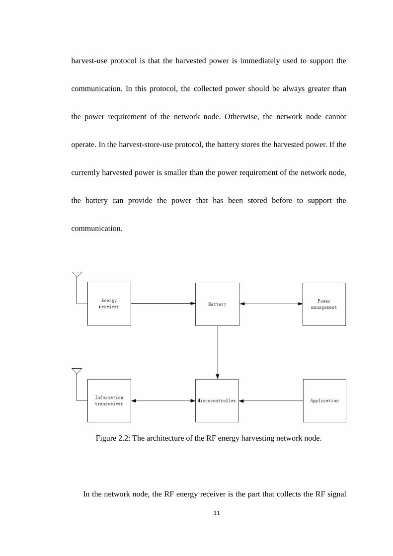
In Fig. (2.2), the architecture of the network node is presented. In order to harvest
the RF signal to convert it into the power, the network node should have an
application operating network functions, a microcontroller processing the data from
the application, an information transceiver for transmitting and receiving the
information-bearing signal, a RF energy receiver harvesting the RF energy-bearing
signal, a power management module deciding how to handle the collected energy and
a battery for storing the redundant energy. For the power management module, it can
use two protocols to manage the energy, i.e., harvest-use and harvest-store-use. The
11
harvest-use protocol is that the harvested power is immediately used to support the
communication. In this protocol, the collected power should be always greater than
the power requirement of the network node. Otherwise, the network node cannot
operate. In the harvest-store-use protocol, the battery stores the harvested power. If the
currently harvested power is smaller than the power requirement of the network node,
the battery can provide the power that has been stored before to support the
communication.
Figure 2.2: The architecture of the RF energy harvesting network node.
In the network node, the RF energy receiver is the part that collects the RF signal

12
and converts it into electricity. The RF energy receiver is composed of an antenna
module, an impedance matching, a voltage multiplier and a capacitor [12]. The
antenna module is capable of operating on various frequency bands to make the RF
energy receiver harvest multiple power sources. The impedance matching is placed
between the antenna module and the voltage multiplier to maximize the power transfer.
The rectifier is the device for converting AC into DC. The capacitor delivers the
converted power to the load. The architecture of the RF energy receiver is presented in
Fig. (2.3).
Figure 2.3: The architecture of the RF energy receiver.
2.2 Wireless Energy Harvesting Technique

13
For the RF energy harvesting, the harvested power can be calculated by Friis equation
[1], which depends on the transmitted power, the wavelength, and the distance. The
received power can be expressed by
𝑃𝑅 = cos2𝜙𝑃𝑇𝐺𝑇4𝜋𝑅2
𝐴𝑒 , (2.1)
where cos𝜙 is the polarization loss factor, 𝑃𝑇 is the transmitted power, 𝐺𝑇 is the
transmitted antenna gain, 𝑅 is the distance between antennas and 𝐴𝑒 is the effective
antenna area. 𝐴𝑒 =𝜆2𝐺𝑅
4𝜋 where 𝜆 is the wavelength and 𝐺𝑅 is the received antenna
gain. The RF energy harvesting also has the distinctive properties compared the other
energy harvesting methods, such as solar, wind, geothermal and vibrations.
Renewable energy sources from nature are uncontrollable, hence the renewable
energy harvesting does not ensure the QoS requirement. The RF energy harvesting
technique overcomes the above limitation, and it uses a power source to broadcasting
constant energy-bearing signal, and the transmitted power is controllable. The RF
energy harvesting can be used in communication networks to charge remotely mobile
devices. Due that the amount of harvested power depends on the distance, different
energy harvesters placed in various locations have the obvious distinction of harvested
14
power. The most significant difference between the RF energy harvesting and other
energy harvesting methods is that the RF energy harvesting can produce the stable
power to the surrounding. Nevertheless, other energy harvesting methods are
uncontrollable, passive to generate power. Hence, the RF energy harvesting is
extremely suitable for the present-day communication network.
There are two kinds of power sources used in the RF energy harvesting, the
dedicated source, and the ambient source. The dedicated power source uses directive
antennas to meet the QoS requirement in the network with the constant transmitted
power. The commercial application of the dedicated power source is the Powercaster
[13] which operates at 915 MHz with 1 W or 3 W transmitted power. Due to the
health and safety of human beings, there are some limitations regarding the output
power of the dedicated RF power source, such as the FCC and the ISM regulation. For
instance, the limitation of the output power is 4 W in the 900 MHz band. To meet
mobile applications’ QoS requirements, the dedicated power source is an appropriate
method to satisfy that, because the dedicated power source can be fully configured. In
[14], [15] and [16], the authors researched different power transfer schemes with the

15
mobile power source in WSNs. The ambient source is the RF signal that has been
transmitted in the wireless channel. The RF energy harvester can opportunistically
collect the ambient RF signal to charge itself. Some ambient RF signals could be
harvested as power, such as the cell phone base station and the signal broadcasted
from TV or radio towers. In [17], the authors analyzed the system performance of a
sensor wirelessly powered by the ambient power source. In [18], the authors proposed
a cognitive radio network model, in which the secondary user can collect RF signal
transmitted from the primary user to power itself for the further use.
2.3 Applications of Wireless Energy Harvesting
A typical application of RF energy harvesting is WSNs. Deploying the RF energy
harvesting in the WSN can be used as the power supply for the sensor node. In [3], a
WSN is wirelessly charged by the ambient power source. The WSN powered by RF
signals in the relaying network was presented in [19], [20], and [21].
Besides, the RF energy harvesting can also be used in the medical field. The node

16
with the medical purpose can be embedded in the human body, and the RF signal can
be used for charging it. The RF energy harvesting technique results in the battery-free
design for the circuit. In [4], an integrated circuit with the energy harvesting function
was proposed, which can be applied in medical body sensors.
The RF energy harvesting technique is useful for RFID used in identification,
tracking and inventory management [22]. Compared the traditional RFID tag, the tag
with the energy harvester has the longer lifetime and the farther range. The RFID tag
with the energy harvester can collect power and operate actively, which can process
data and manage power [23].
The RF energy harvesting can also be used to power many wireless devices used
in our daily life, such as wearable devices, electronic devices. In [24], a proposed
circuit can be applied in mobile devices to harvest the ambient RF signal to supply
devices operating.
2.4 Wireless Information and Power Transfer

17
The network node in the RF energy harvesting network has the information receiver
and the energy receiver. Theoretically, it can collect energy and process information
simultaneously. The RF signal can carry both information and energy, so the network
node with the RF energy harvester can receive both information and power from the
same RF waveform, which is referred as SWIPT and was firstly proposed in [25].
SWIPT is that the network node uses the same antenna module to perform the
information reception and the energy harvesting. For instance, the wireless body
sensor can be powered by the control signal. SWIPT achieves more efficient spectrum
usage than that information and energy are transmitted in orthogonal time or
frequency channels [6], [26]. SWIPT can be used in many scenarios with low-power
electronic devices. The ideal receiver is capable of harvesting energy and receiving
information from the same RF signal. Some works considered the ideal receiver to
analyze the upper bound of the performance [25], [27], [28], [29].
However, the existing circuit cannot support simultaneously processing the
information reception and the energy harvesting. The information reception and the
energy harvesting cannot be operated on the same signal. Because the power

18
sensitivities of the information reception and the energy harvesting are different [6].
During the information receiving processing, the energy in the RF signal will be lost.
Hence, to design a practical implementation for SWIPT becomes a new research field.
2.4.1 Separated Structure
The separated structure is introduced in [6], in which the information reception
and the energy harvester use different sets of the antenna. Their antennas receive the
same RF signal. The structure is presented in Fig. (2.4). The separated structure can
concurrently receive information and harvest energy. The separated structure is also
referred as the antenna switching. MIMO technique could improve the performance
for both the data reception and the energy harvesting with the antenna switching. For
example, there are 𝑁 antennas in total, in which 𝐿 antennas serve the information
reception, and (𝑁 − 𝐿) antennas serve the energy harvester. In [6], multiple antennas
were equipped with the either the information reception or the energy harvester, which
significantly reduces the system complexity and is easy to implement. In [30], a low

19
complexity antenna switching was used at a relay node to achieve harvesting energy
and decoding information. In the energy harvesting with the separated structure, the
resource allocation can be performed at the power source when the CSI is available.
Figure 2.4: Separated receiver structure.
20
2.4.2 Time Switching and Power Splitting
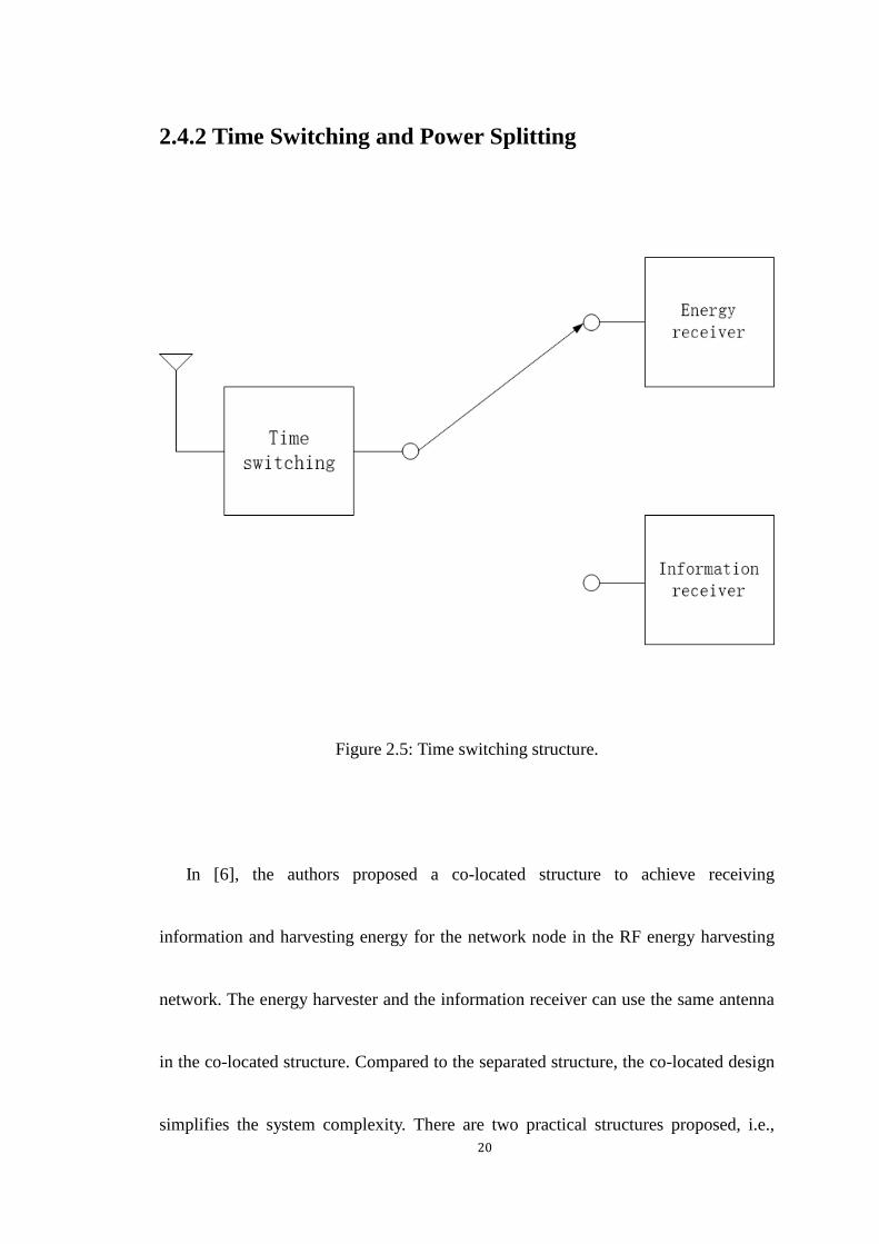
Figure 2.5: Time switching structure.
In [6], the authors proposed a co-located structure to achieve receiving
information and harvesting energy for the network node in the RF energy harvesting
network. The energy harvester and the information receiver can use the same antenna
in the co-located structure. Compared to the separated structure, the co-located design
simplifies the system complexity. There are two practical structures proposed, i.e.,

21
time switching and power splitting. According to the time switching, the energy
harvesting node switches between collecting power and receiving information during
different time allocations. The structure of the time switching is showed in Fig. (2.5).
When the energy harvester collects power, the harvested energy can be expressed as
𝑃𝑒ℎ = 𝜂𝑃𝑡|ℎ|2, (2.2)
where 𝜂 is the energy conversion coefficient, 𝑃𝑡 is the transmitted power at the
power source, and ℎ is the channel gain between the transmitter and the receiver.
When the information receiver operates, the information rate can be expressed as
𝑅 = (1 − 𝛼)𝑊 log (1 +𝑃𝑡|ℎ|
2
𝜎2), (2.3)
where 𝛼 is the time switching coefficient that the duration of receiving energy at the
receiver while 1 − 𝛼 represents the duration of receiving information at the receiver,
𝑊 is the bandwidth and 𝜎 is the standard deviation of noise. The time switching
allocation can be jointly optimized with the transmitted signal in different
communication networks. The time switching requires accurate scheduling for the
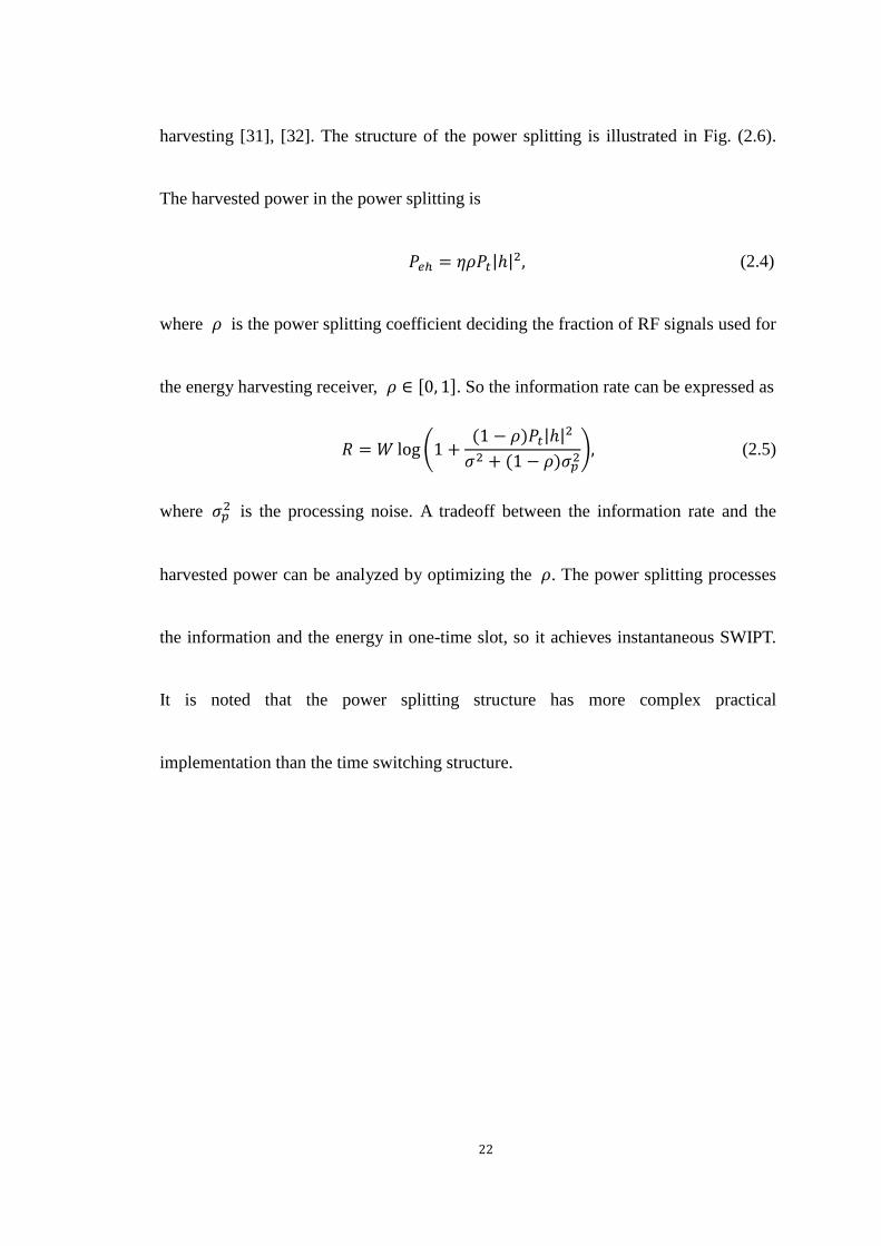
information and the energy. For the power splitting, the received RF signal is split into
two streams, one is for the information reception, and the other one is for the energy
22
harvesting [31], [32]. The structure of the power splitting is illustrated in Fig. (2.6).
The harvested power in the power splitting is
𝑃𝑒ℎ = 𝜂𝜌𝑃𝑡|ℎ|2, (2.4)
where 𝜌 is the power splitting coefficient deciding the fraction of RF signals used for
the energy harvesting receiver, 𝜌 ∈ [0, 1]. So the information rate can be expressed as
𝑅 = 𝑊 log (1 +(1 − 𝜌)𝑃𝑡|ℎ|
2
𝜎2 + (1 − 𝜌)𝜎𝑝2), (2.5)
where 𝜎𝑝2 is the processing noise. A tradeoff between the information rate and the
harvested power can be analyzed by optimizing the 𝜌. The power splitting processes
the information and the energy in one-time slot, so it achieves instantaneous SWIPT.
It is noted that the power splitting structure has more complex practical
implementation than the time switching structure.

23
Figure 2.6: Power splitting structure.
2.4.3 Integrated Structure
In [26], the integrated structure was proposed, in which the information reception
and the energy harvesting are implemented at the rectifier. The architecture is showed
in Fig. (2.7). It is important to note that at the RF flow controller in the integrated
structure, a time switching and a power splitting can be applied. When the circuit
power consumption is considered as negligible compared to the signal power, the

24
co-located structure outperforms the integrated structure at the low harvested energy
region [26].
Figure 2.7: Integrated receiver structure.
To achieve efficient SWIPT, the design of communication networks should be
changed. It was common to use the information rate to evaluate the reliability of the
communication. But in the wireless energy harvesting network, the amount of
harvested power becomes a parameter as important as the information rate. The
channel fading and the interference have a significant impact on the system
performance. The channel fading causes the degradation for the information reception
and the energy harvesting in SWIPT. The interference attenuates the information

25
reception but is beneficial to the energy harvesting. In [33], the authors optimized the
average data rate with the time switching structure under an average energy harvesting
constraint in the interference fading channel. The authors in [34] also analyzed the
power splitting in the fading channel.
2.5 Literature Review for SWIPT
2.5.1 Energy Harvesting Protocols
The energy harvesting protocol design is an important issue in the wireless energy
harvesting network, in which the information receiver and the energy harvesting
intends to use the same single antenna or multiple antennas. To meet QoS
requirements, various tradeoffs are analyzed in the physical layer regarding the energy
harvesting protocol. Scores of works considered the time switching and the power
splitting protocol. The time switching is scheduling the arrival of information and
energy in different time slots. The power splitting is dividing the received signal to

26
serve respectively the information receiver and the energy harvester.
Many researches regarding the energy harvesting protocol study were based on the
point-to-point SISO system. In [6], [26], [34] and [35], the authors considered the
energy harvesting in the fading channel. In [33], [36] and [37], the co-channel
interference was involved in the wireless energy harvesting network study. In [6], the
time switching was analyzed with the fixed transmitter power constraint or the
flexibly transmitted power constraint; A uniform power splitting was also used in the
receiver design, in which all antennas deployed the same power splitting ratio; The
antenna switch employed in this paper implemented two groups of antenna to perform
harvesting energy and receiving information; The achievable rate-energy regions for
different energy harvesting protocols were illustrated.
A dynamic power splitting was proposed in [26], in which the receiver used
dynamic ratio for the power splitting protocol. A unique scenario for the dynamic
power splitting was demonstrated in this paper, i.e., the on-off power splitting. In the
on mode, the receiver used the power splitting, in the off mode, the receiver only
performed the energy harvesting. It is noted in this paper that when the circuit

27
consumption was considered in the system design, the on-off power splitting
outperformed the power splitting.
In [35], it is proposed that the training assisted the power splitting receiver to
improve the system performance. In the transmission phase, the transmitter was in the
training phase and the information phase. The receiver used different power splitting
ratios for the training phase and the information phase to achieve the better
information rate. A non-adaptive and an adaptive power splitting were used in this
paper. For the non-adaptive power splitting, the power splitting ratio was fixed. For
the adaptive power splitting, the power splitting was changeable. It is proved that the
adaptive power splitting outperformed the non-adaptive power splitting.
The wireless energy harvesting network with time-varying co-channel
interferences in the fading channel was studied in [33]. According to the instantaneous
CSI, an opportunistic time switching was used to estimate the system performance in
delay-tolerant and delay-limited networks. Also, a joint optimization of the
transmitted power and the receiver protocol was investigated. It is proposed that the
receiver could either harvest energy or receive information according to the fading

28
channel information. Another result was that to achieve better system performance in
the fading channel, it was reasonable to allocate the best channel gains for energy
harvesting.
The power splitting was employed in both SISO and SIMO fading contexts [34].
In this paper, the authors proposed that if the fading channel gain surpassing the
particular value, the receiver should perform power splitting according to a fixed
coefficient, otherwise, the receiver only performed the information reception. The
authors also proposed that a power splitting method was used in an SIMO model, in
which a uniform power splitting method helped the system achieving the optimal
performance.
A spectral efficient optimization problem was proposed in an OFDM system with
the fading channel [36]. The problem of maximizing the spectral efficiency with the
constraint of transmitted power and energy harvesting coefficient was non-convex. A
convex technique was used in the paper, and the energy harvesting coefficient was
found by the full search. Two low complexity algorithms were used to optimize the
complexity. The same authors in [37] studied the energy efficiency problem. The

29
original problem to maximize the energy efficiency was also non-convex. An iterative
algorithm was employed to solve the problem in the paper, and the algorithm could be
guaranteed to converge to an optimal solution.
Some papers considered the wireless energy harvesting network in the SISO
broadcasting model [32], [38]. In [32], a joint optimization problem of transmitted
power allocation, sub-carrier allocation and energy harvesting coefficient was
proposed for an OFDM network. The non-convex problem was solved by using
fractional programming and iterative algorithm. In [38], the energy harvesting
protocol was considered with TDMA and OFDM. The objective function in this paper
was to maximize the sum-rate for all receivers with constraints of transmitted power
and harvested energy. A TDMA-based and an OFDM-based transmission designs
were proposed in the article.
In the above mentioned papers, the energy harvesting protocols are mainly
investigated in single antenna communication network models. Some researchers
studied the energy harvesting protocols in the fading channel to find an optimal
energy harvesting coefficient, which improves the system performance for the

30
wireless energy harvesting network. However, some researcher pointed out that the
single-antenna node could not achieve the high energy transfer efficiency, hence, there
are other papers studying the energy harvesting technique in the multi-antenna
network, in which the multi-antenna network could provide the better system
performance than the single-antenna network. In the next subsection, some papers
regarding the energy harvesting study in the multi-antenna network will be discussed.
2.5.2 Energy Harvesting for Multi-Antenna Network
2.5.2.1 Beamforming Design for Resource Allocation
There is a major challenge regarding the wireless energy harvesting, which is the
degradation of energy according to the transmission distance. The single-antenna
network with the energy harvesting node transmits power via omnidirectional
emission due to the broadcasting nature of the wireless communication. In this
situation, the multi-antenna can assist the transfer of energy. The multi-antenna

31
transmitter produces more transmitted power for energy harvesters than the single
antenna transmitter. Also, the beamforming technique can improve the energy transfer
efficiency for SWIPT [39] and has been considered as a potential way to practically
implement the energy harvesting [8], [40], [41]. In the wireless energy harvesting
network, the beamforming design is used to delivery information and energy from a
transmitter to several receiver nodes. It is showed in Fig. (2.8) regarding a
multi-antenna SWIPT network.
32
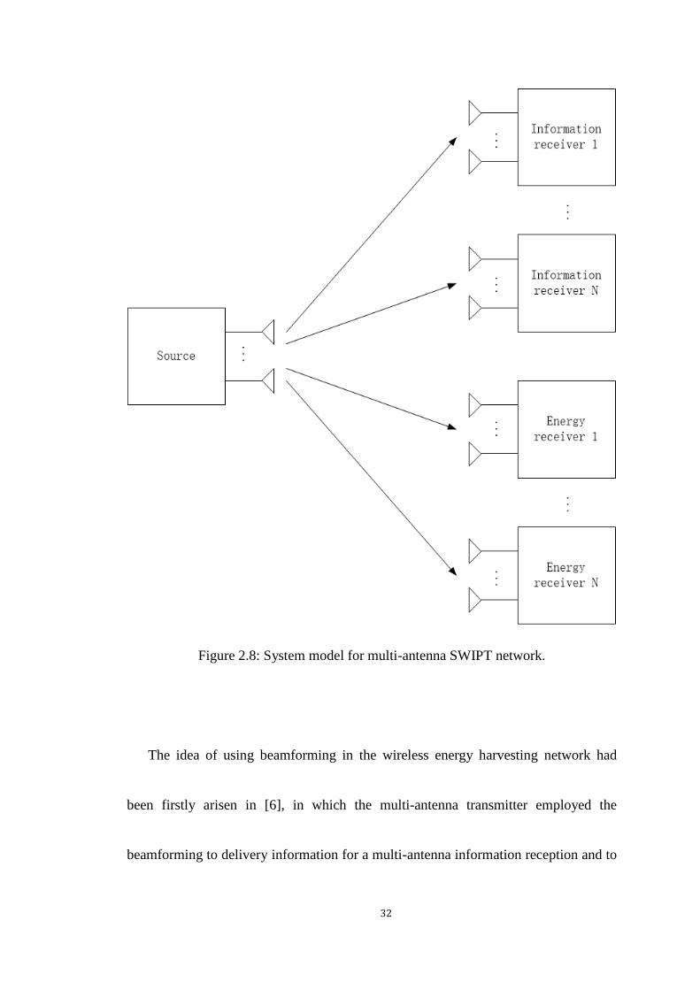
Figure 2.8: System model for multi-antenna SWIPT network.
The idea of using beamforming in the wireless energy harvesting network had
been firstly arisen in [6], in which the multi-antenna transmitter employed the
beamforming to delivery information for a multi-antenna information reception and to
33
transfer power for a multi-antenna energy harvester. In [39], the beamforming
technique was deployed to improve the energy efficiency of the MIMO network. A
joint optimization problem regarding the transmitted power and the energy harvesting
coefficient was solved. The study in [42] was to optimize the harvested power with
the constraint of information rate, in which the non-convex problem was solved by the
semidefinite relaxation and the solution was theoretically proved as always rank-one.
The MISO model for SWIPT network with multiple information receivers and
energy harvesters was studied in [43] and [44]. A problem designed to optimize the
harvested energy for energy harvesting nodes with constraints of each SINR for
information receivers and the total available power was proposed in [43]. A standard
interior-point method was used to solve this problem. In [44], the total harvested
energy was maximized for energy harvesters with the constraint of QoS requirements
for each information receiver.
In [45], the authors proposed to use multiple power splitting receivers instead of
multiple separated information receivers and energy harvesters in the MISO network.
A joint optimization problem of the transmitted beamforming and the power splitting

34
coefficient was proposed, and it was solved via the semidefinite relaxation.
Figure 2.9: The co-channel interference SWIPT network.
The scenario of the co-channel interference was considered in SWIPT. The multi
transmitter-receiver pairs are significant for SWIPT; its structure can be showed in Fig.
(2.9). The multi-nodes share the spectrum. This case is different from the single
transmitter-receiver pair, in which information and interference signals co-exist in

35
channels. Interference collaboration has become a challenge for SWIPT. An antenna
selection technique and interference management were introduced in [46], it was
proved that interference signals was used to be considered as harmful for
communications but became useful in wireless energy harvesting networks. A
diagonalization block precoding was used in [47], in which receivers switched
between the information reception and the energy harvester to improve the system
performance. In [48], a beamforming optimization problem was designed in a MISO
network with multiple transmitter-receiver pairs. Different beamforming designs were
used in this paper, and a joint optimization of the beamforming and the power splitting
coefficient was solved via semidefinite relaxation. Moreover, an adaptive
beamforming design was proposed in this paper. In [49] and [50], the authors studied
SWIPT in MIMO model with the co-channel interference. The scenario of two
transmitter-receiver pairs was considered in [49], in which receivers used the time
switching structure. The information rate was analyzed by an iterative water-filling
method. In [50], the research in [49] was extended to a k-user multiple
transmitter-receiver pairs network. Beamforming designs were proposed in this paper,
36
and the rate-energy region was also analyzed. A non-convex optimization was solved
by proposed iterative algorithm.
The authors proposed a multi-point network with SWIPT in [51], in which a
central processor assisted the transmission between transmitters and multi-point nodes.
A non-convex optimization problem of minimizing the available power with
constraints of QoS requirements for information receptions and minimum harvested
energy for energy collectors was solved by a proposed suboptimal iterative algorithm.
In the above mentioned papers, the beamforming technique was studied in the
energy harvesting multi-antenna network. It is proved that the beamforming technique
can improve the system performance with SWIPT. Some beamforming optimization
problems were proposed in the above papers and their optimal solution were found. In
the next subsection, some researchers focused on the beamforming studies regarding
the security problem with SWIPT.
2.5.2.2 Beamforming Design for Secure Communication

37
Some studies focused on the secure issue regarding the wireless energy harvesting
network, and beamforming could also be used in secure communication networks for
SWIPT. The authors studied two optimization problems in [52], one was maximizing
the secrecy rate with the constraint of minimum harvested energy, another was
maximizing the harvested energy with the constraint of secrecy rate. The proposed
problems were non-convex, and the authors used the one-dimension method and the
semidefinite relaxation to solve problems. In [31], the authors used the artificial noise
to improve the system performance from the security’s perspective. The proposed
problem in this paper was to minimize the transmitted power with the constraint of
information rate.
The authors considered a secure issue for a TDMA-based broadcasting network
with multiple information receiver and eavesdroppers. A semidefinite relaxation
algorithm was used to solve the power allocation with the consideration of QoS.
In [53], a three nodes MIMO network was used to study the secure issue, in which
the energy harvester was malicious to hear information. The original non-convex
beamforming optimization problem was intended to maximize the secrecy rate with

38
constraints of transmitted power and minimum harvested energy. An inexact block
coordinate descent algorithm was proposed in the paper for this issue.
The secure issue was considered in a cognitive radio network with SWIPT [54]. In
the proposed network, the authors optimized the energy harvesting efficient and the
transmitted power via the semidefinite relaxation. Two suboptimal algorithms were
also proposed in the paper.
In the above mentioned papers, the secure issue in the wireless energy harvesting
multi-antenna network was considered. So far, we have reviewed some literatures
regarding the energy harvesting in the point-to-point communication network. To
practically implement the energy harvesting in the communication network, the fading
and attenuation problems should be overcome. Some researchers pointed out that the
cooperative network could improve the system performance for the energy harvesting
network by deploying the relay node in the network. In the next subsection, some
studies regarding the cooperative network will be introduced.
2.5.3 Cooperative Relaying Network

39
2.5.3.1 Introduction of Conventional Relaying Network
For the point-to-point communication network, the channel state between nodes
cannot be guaranteed to support the continuous communication due to the multipath
fading. In the cooperative relaying network, the source node communicates with the
destination node through the relay node. The diversity in the cooperative network is
improved [55], because the additional paths are provided for the reception. Each node
in the cooperative network has a closer distance as the transmission is split into
several phases, therefore the pathloss impact becomes slighter. The source-destination
transmission is reliable with the assist of the relay node. The relay node uses different
relaying protocols to assist the cooperative network transmission. In the thesis, the
works are mainly based on the AF and DF protocol, therefore these two protocols will
be discussed here.
The AF relaying protocol was firstly proposed in [56]. In the AF protocol, the
relay node amplifies the received signal from the source node and then transmits it to
the destination node. If the relay node has the minimal computing power, the AF

40
protocol is the ideal and straightforward way to deploy in the cooperative network.
The DF relaying protocol is another common protocol used at the relay node. In
this protocol, the relay node detects the signal from the source node and then transmits
it to the destination node. If the relay node has the enough computing power, it can
employ the error correcting code to correct the received bit error [57].
As the cooperative relaying network could overcome fading to increase the
transmission efficiency and reliability, this network is suitable for the wireless energy
harvesting network. In the thesis, the energy harvesting technique is studied in the
wireless cooperative network. In the next subsection, some researches regarding the
wireless energy harvesting cooperative network will be discussed.
2.5.3.2 Relaying Protocols with Energy Harvesting
The cooperative relaying network is promising to implement practically the wireless
energy harvesting because it is powerful to improve the system performance in
communications. In the wireless energy harvesting network, the relay node can be

41
powered by signals. For instance, a source node is willing to communicate to a
destination node with the help of a relay node. The relay node has a limited battery to
support the transmission. If the relay node can wirelessly harvest energy, the relay
node can have enough power to support the transmission. Also, the relay node can
assist the communication to overcome fading and attenuation. Hence, the energy
harvesting relay can improve the transmission reliability.
The design of the cooperative relaying network with energy harvesting is different
from it without energy harvesting. The deployment of energy harvesting node should
be considered in the cooperative relaying network. Typically, there are three nodes in
the cooperative relaying network, which are the source node, the relay node, and the
destination node. The relay node deliveries information from the source node to the
destination node. Energy harvesting can be deployed on one node or multiple nodes in
the cooperative relaying network. Some cooperative schemes have been widely used
for nowadays applications, such as AF and DF. The authors in [58] proposed that DF
relaying scheme be more practical to implement for SWIPT.
In [59], the authors employed the time switching in the cooperative relaying

42
network. In proposed network, the relay node used remaining power to delivery
information. The outage probability of the relay node was obtained in a close form.
The multi-antenna is important for the cooperative relaying network with energy
harvesting. In [30], an MIMO relaying was considered with energy harvesting. A
dynamic antenna switching was deployed to allocate sets of the antenna to perform
information receiving or energy harvesting according to CSI. The outage probability
was analyzed in the paper.
The authors in [60] proposed the time switching based relaying protocol and the
power splitting based relaying protocol for the wireless cooperative relaying network
using AF. Capacities and outage probabilities for two proposed protocols were
analyzed in the paper. The same authors proposed an adaptive time switching protocol
for AF and DF wireless cooperative relaying network [61]. The duration for
harvesting energy was dynamically changed according to CSI. The achievable
throughput was analyzed. The concern of user scheduling was proposed in [62], the
max-min selection criterion and an optimal strategy for DF relaying network were
investigated.
43
In this subsection, the papers about the wireless energy harvesting network are
discussed. From those papers, it can be seen that the cooperative relaying network
could improve the system performance with SWIPT. In the next subsection, some
resource allocation problems in the energy harvesting relaying network will be
introduced.
2.5.3.3 Resource Allocation for Energy Harvesting Relaying
Network
Resource allocation algorithms is another research area for the wireless energy
harvesting cooperative relaying network. The authors in [63] studied the resource
allocation in multiple transmitter-receiver pairs DF relaying network. The relay node
was able to harvest power and assist the transmission. The usage of harvested power
in the relay node was optimized for each transmitter-receiver pair.
In [64], the model used was that multiple sources transmitted information to one
destination with the help of one relay. The sources and the relay were able to harvest

44
power. A joint resource allocation and energy harvesting problem was proposed to
maximize the sum rate, and an iterative algorithm solved the problem. Also, an energy
cooperation model for the two-way relaying network was analyzed in [65].
Some works focus on the application of SWIPT for the two-way cooperative
relaying network. In [66], a two-way cooperative relaying network with energy
harvesting was considered. In fading channels, the relay node assisted two nodes to
exchange information and the power splitting was employed in the paper. In [67], two
single-antenna nodes wirelessly powered by multiple single-antenna relay nodes
shared information. The sum rate of all nodes was optimized with constraints of
transmitted power and harvested energy. The work in [68] studied a robust
optimization problem for the two-way cooperative relaying network. The semidefinite
relaxation, S-procedure, and successive convex approximation were used in the paper
to obtain the optimal solution.
In this subsection, some resource allocation algorithms are discussed regarding the
wireless energy harvesting cooperative network and some methods to find the optimal
solution are introduced. Based on the above researches, the works in this thesis are

45
mainly focused on the resource allocation algorithm for the wireless energy harvesting
cooperative network. In the next chapter, these works will be introduced.
2.6 Chapter Summary
This chapter provides a background of wireless energy harvesting. The architecture of
wireless energy harvesting network is introduced. Some wireless energy harvesting
techniques and applications are explained. Also, the concept of SWIPT and different
SWIPT receiver structures are discussed in detail. Literature reviews regarding
SWIPT are also provided in this chapter.

46
Chapter 3
Energy-Efficient Optimization in Cooperative Networks
with Wireless Information and Power Transfer
3.1 Introduction
The concept of energy efficiency (bit-per-Joule) in the wireless communication has
drawn much attention in industry and academia fields [69], [70], [71]. For the wireless
energy-constrained network, the energy-efficient design is a significant issue [72],
[73], [74]. Improving the energy efficiency can ensure that the wireless
communication system utilizes energy in a more environment-friendly way.
In the chapter, a DF cooperative relaying network is considered, in which the
energy harvesting relay is wirelessly powered by RF signals transmitted from the
source node and then uses the harvested energy to support the relay transmission. The
energy-efficient maximization problem in the cooperative wireless network is
considered. The energy-efficient maximization problem is a ratio of the channel

47
capacity and overall power consumption in the block time. Notably, two
energy-efficient maximization problems are formulated in this chapter based on the
time switching relaying protocol and the power splitting relaying protocol,
respectively. However, original formulated maximization problems are not in a
standard convex form, which is not solvable. In this situation, the nonlinear fractional
programming is useful to reconstruct proposed problems into a convex form. After the
transformation, the Lagrange multiplier method and the gradient method are used to
solve problems. The simulation results are also presented in the chapter to verify the
effectiveness of proposed method.
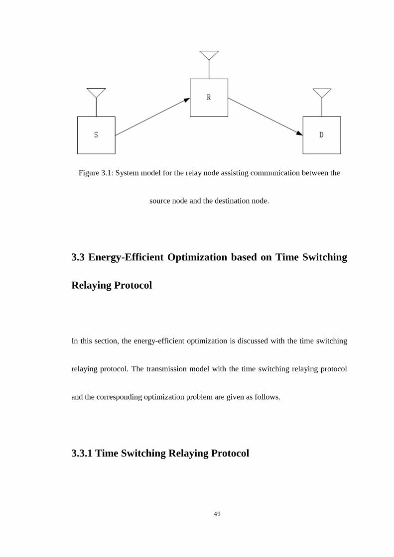
3.2 System Model
The considered wireless cooperative network includes one source-destination pair and
one relay. Each node in the network is equipped with a single antenna. There is no
direct link between the source node and the destination node, i.e., the source node
communicates with the destination node via an energy harvesting relay. The

48
source-to-relay channel and the relay-to-destination channel are modeled as
quasi-static block fading channels. The channel gains are denoted as ℎ and 𝑔. The
distances from the source to the relay and from the relay to the destination are denoted
by 𝑑1 and 𝑑2, respectively. The considered network is demonstrated in Fig. (3.1).
The prefect channel state information is assumed available at the destination node.
The energy harvesting relay can harvest energy from the source node and utilize the
energy to relay the source information and this assumption is used in [60]. The battery
capacity of the energy harvesting relay is assumed as infinite. The DF scheme is
employed in the cooperative network. The two relaying protocols for energy
harvesting are considered in this paper. Detailed analyzes regarding the time
switching-based relaying protocol and the power splitting-based relaying protocol are
given in the following sections. Assuming that at the relay, the power consumed to
process the harvested energy is negligible, when compared to the power used in
transmitting information to the destination.
49
Figure 3.1: System model for the relay node assisting communication between the
source node and the destination node.
3.3 Energy-Efficient Optimization based on Time Switching
Relaying Protocol
In this section, the energy-efficient optimization is discussed with the time switching
relaying protocol. The transmission model with the time switching relaying protocol
and the corresponding optimization problem are given as follows.
3.3.1 Time Switching Relaying Protocol

50
The whole transmission process is operated in the block time, denoted by 𝑇. The
information transmission process is split into three phases. In the first phase, the
source node transmits RF signals to power the energy harvesting relay node for 𝛼
time, 0 ≤ 𝛼 ≤ 1. During the rest of the block time (1 − 𝛼), the information is
transmitted from the source node to the relay node and then to the destination node.
3.3.2 System Transmission Model
The energy harvesting relay first harvests the energy from the source and then detects
the transmitted signal from the source. The received signal at the relay can be
expressed as
𝑦𝑟 =1
√𝑑1𝑚√𝑃𝑠ℎ𝑠 + 𝑛𝑟 , (3.1)
where 𝑑1 is the distance between the source node and the relay node, 𝑚 is the path
loss exponent, 𝑃𝑠 is the transmitted power, ℎ is the channel gain from the source
node to the relay node which is modeled as quasi-static block-fading and frequency
non-selective parameters, the channel is unchanged in the block time and independent

51
and identically distributed from one block to the next block, following a Rayleigh
distribution, and 𝑠 is the normalized transmitted signal with the unit power. 𝑛𝑟 is
the sum of the baseband AWGN from the receiving antenna and the sampled AWGN
from the RF band to baseband conversion [60], following 𝒞𝒩(0, 𝜎𝑟2).
The energy harvesting relay harvests energy from the source in 𝛼 time, in which
the harvested energy is given by
𝐸 =𝜂(𝑃𝑠|ℎ|
2 + 𝑑1𝑚𝜎𝑟
2)
𝑑1𝑚 𝛼𝑇, (3.2)
where 𝜂 is the energy conversion efficiency coefficient at the relay node.
We assume that the energy harvesting relay is operated with the DF protocol, and
it can decode the source information successfully. The received signal at the
destination is given by
𝑦𝑑 =1
√𝑑2𝑚√𝑃𝑟𝑔𝑠 + 𝑛𝑑 , (3.3)
where 𝑑2 is the distance from the relay to the destination, 𝑃𝑟 is the power
transmitted from the relay; 𝑔 is the channel gain between the relay and the
destination which is also modeled as quasi-static block-fading and frequency
non-selective parameters, the channel is stable in the block time and independent and

52
identically distributed from one block to the next block, following a Rayleigh
distribution. 𝑛𝑑 is the sum of the AWGN from the receiving antenna and the noise
from the conversion, following 𝒞𝒩(0, 𝜎𝑑2).
According to the time switching relaying protocol, the relay uses the harvested
energy in 𝛼 time to forward the re-encoded information to the destination in the rest
of the time. The transmitted power at the relay can be expressed as
𝑃𝑟 =2𝜂(𝑃𝑠|ℎ|
2 + 𝑑1𝑚𝜎𝑟
2)𝛼
𝑑1𝑚(1 − 𝛼)
, (3.4)
In the case of the cooperative network using DF protocol without the direct link
between the source node and the destination node, the channel capacity with the time
switching relaying protocol can be calculated as
𝐶𝑇𝑆 = min(𝐶𝑆𝑅𝑇𝑆, 𝐶𝑅𝐷
𝑇𝑆), (3.5)
where 𝐶𝑆𝑅𝑇𝑆 and 𝐶𝑅𝐷
𝑇𝑆 are channel capacities from the source to the relay and from the
relay to the destination, respectively. Based on the time switching energy harvesting
relaying protocol, 𝐶𝑆𝑅𝑇𝑆
and 𝐶𝑅𝐷𝑇𝑆
can be expressed as
𝐶𝑆𝑅𝑇𝑆 =
1 − α
2log2 (1 +
𝑃𝑠|ℎ|2
𝑑1𝑚𝜎𝑟2
), (3.6)
and

53
𝐶𝑅𝐷𝑇𝑆 =
1 − α
2log2 (1 +
2𝜂(𝑃𝑠|ℎ|2 + 𝑑1
𝑚𝜎𝑟2)|𝑔|2𝛼
𝑑1𝑚𝑑2
𝑚(1 − 𝛼)𝜎𝑑2 ), (3.7)
where 𝜎𝑟2 and 𝜎𝑑
2 are variances of 𝑛𝑟 and 𝑛𝑑.
3.3.3 Problem Formulation
In this subsection, we consider the ratio between the system channel capacity and the
overall power consumption in one transmission block time, which is the expression of
the energy efficiency. It is assumed that each node has a constant circuit power
consumption for signal processing, which is independent of the power used for
transmitting signal. We denote 𝑃1, 𝑃2 and 𝑃3 by the consumed circuit power in the
source, the relay, and the destination, respectively.
In the time switching relaying protocol, nodes are activated in the allocated time
slot. The source node operates during the energy transfer time and information
delivering to the relay node. The relay node operates for the whole transmission block.
The destination node operates during the information being transmitted from the relay
to itself. So the total consumed energy with the time switching relaying protocol in

54
this cooperative wireless network is given by
𝐸𝑐𝑇𝑆 = 𝑃1 (
1 + α
2)𝑇 + 𝑃2𝑇 + 𝑃3 (
1 − α
2)𝑇 + 𝑃𝑠 (
1 + α
2)𝑇, (3.8)
This work aims to maximize the energy efficiency in the considered model. The
energy efficiency can be expressed as the ratio of the channel capacity and the total
consumed power. With the time switching relaying protocol, the optimization problem
is given by
max𝑃𝑠,𝛼
𝐶𝑇𝑆
𝐸𝑐𝑇𝑆
𝑠. 𝑡. 𝐶1:𝑃𝑠 ≤ 𝑃𝑠𝑚𝑎𝑥 ,
𝐶2:𝑃𝑟 ≥ 𝑃𝑟𝑚𝑖𝑛,
𝐶3:𝐶𝑇𝑆 ≥ 𝐶𝑚𝑖𝑛,
𝐶4:𝑃𝑠 ≥ 0,
𝐶5:0 ≤ 𝛼 ≤ 1. (3.9)
where the predefined variable 𝑃𝑠𝑚𝑎𝑥 is the maximum transmitted power limitation at
the source. 𝑃𝑟𝑚𝑖𝑛 is the minimum power requirement at the relay to forward the
information to the destination. 𝐶𝑚𝑖𝑛 is the minimum required channel capacity to
meet the QoS criterion.

55
One can easily verify that the proposed problem above is not a convex
optimization problem because the objective function is a ratio of the channel capacity
and total consumed power. The solution of this formulated problem is given in
following sections.
3.4 Energy-Efficient Optimization based on Power Splitting
Relaying Protocol
In this section, we focus on energy-efficient optimization based on the power
splitting-based relaying protocol. The transmission model with power splitting
relaying protocol and the optimization problem are given as follows.
3.4.1 Power Splitting Relaying Protocol
In the cooperative wireless network with the power splitting relay, one transmission
block is split into two phases. At the end of the first phase, the power splitting relay

56
receives observations with the transmitted power 𝑃𝑠 from the source and then splits it
into two streams. One part of the power 𝜌𝑃𝑠 is the harvested energy for the next
phase transmission. The rest of power (1 − 𝜌)𝑃𝑠 is used for information decoding
procedure at the relay.
3.4.2 System Transmission Model
The energy harvesting relay receives the power and theinformation in the first phase.
The received signal is givenby
𝑦𝑟 =1
√𝑑1𝑚√(1 − 𝜌)𝑃𝑠ℎ𝑠 + 𝑛𝑟 , (3.10)
where 𝑑1𝑚 , 𝑚, ℎ and 𝑠 are defined as same as them in the last section. 𝑛𝑟 =
√(1 − 𝜌)𝑛𝑟𝑎 + 𝑛𝑟
𝑐 , the baseband AWGN 𝑛𝑟𝑎 is reduced by the power splitting
receiver and 𝑛𝑟𝑐 is the noise from the conversion.
The relay harvests energy from the source in the first phase, in which the
harvested energy can be expressed as
𝐸 =𝜂𝜌(𝑃𝑠|ℎ|
2 + 𝜎𝑟2)
𝑑1𝑚
𝑇
2, (3.11)

57
where 𝜂 is the energy conversion coefficient at the relay.
The considered model is operated under the DF mode, and it is assumed that the
relay can decode the source information successfully. The received signal at the
destination can be expressed as
𝑦𝑑 =1
√𝑑2𝑚√𝑃𝑟𝑔𝑠 + 𝑛𝑑 , (3.12)
where 𝑑2𝑚, 𝑃𝑟, 𝑔 and 𝑛𝑑 are defined as same as them in the last section.
In the power splitting relaying protocol, the relay utilizes the harvested energy to
assist the next transmission phase. The transmitted power of the relay is given by
𝑃𝑟 =𝜂𝜌(𝑃𝑠|ℎ|
2 + 𝜎𝑟2)
𝑑1𝑚 , (3.13)
The channel capacity in this model can be calculated as
𝐶𝑃𝑆 = min(𝐶𝑆𝑅𝑃𝑆, 𝐶𝑅𝐷
𝑃𝑆), (3.14)
where
𝐶𝑆𝑅𝑃𝑆 =
1
2log2 (1 +
(1 − 𝜌)𝑃𝑠|ℎ|2
𝑑1𝑚𝜎𝑟2
), (3.15)
and
𝐶𝑅𝐷𝑃𝑆 =
1
2log2 (1 +
𝜂𝜌(𝑃𝑠|ℎ|2 + 𝜎𝑟
2)|𝑔|2
𝑑1𝑚𝑑2
𝑚𝜎𝑑2 ), (3.16)
where 𝜎𝑟2 and 𝜎𝑑
2 are variances of 𝑛𝑟 and 𝑛𝑑, respectively.

58
3.4.3 Problem Formulation
To formulate the energy efficiency maximization problem with the power splitting
relaying protocol, we first find the overall energy consumption as follows.
𝐸𝑐𝑃𝑆 =
1
2𝑃1𝑇 + 𝑃2𝑇 +
1
2𝑃3𝑇 +
1
2𝑃𝑠𝑇, (3.17)
where 𝑃1, 𝑃2 and 𝑃3 are the constant circuit power consumption at the source node,
the relay node, and the destination node, respectively.
The energy efficiency maximization problem with the power splitting relaying
protocol can be expressed as
max𝑃𝑠,𝜌
𝐶𝑃𝑆
𝐸𝑐𝑃𝑆
𝑠. 𝑡. 𝐶1:𝑃𝑠 ≤ 𝑃𝑠𝑚𝑎𝑥 ,
𝐶2:𝑃𝑟 ≥ 𝑃𝑟𝑚𝑖𝑛,
𝐶3:𝐶𝑃𝑆 ≥ 𝐶𝑚𝑖𝑛,
𝐶4:𝑃𝑠 ≥ 0,
𝐶5:0 ≤ 𝜌 ≤ 1. (3.18)

59
where 𝑃𝑠𝑚𝑎𝑥 is the maximum transmitted power at the source. 𝑃𝑟
𝑚𝑖𝑛 is the minimum
power requirement at the relay to forward the information to the destination. 𝐶𝑚𝑖𝑛 is
the minimum required channel capacity with a targeted QoS.
This problem is also not a convex problem. In the next section, we analyze the
solution to solve these optimization problems.
3.5 Solution of Formulated Optimization Problems
The two proposed problems are not in the standard convex form. However, the
problem can be transformed by exploring the properties of the nonlinear fractional
programming. According to the parametric method, we introduce a new variable 𝑞∗
to denote the optimum energy efficiency for proposed problems, which is the ratio of
channel capacity 𝐶 and power consumption 𝐸𝑐. 𝑞∗ can be expressed as
𝑞∗ =𝐶∗
𝐸𝑐∗
= max𝑃𝑠
𝐶
𝐸𝑐, (3.19)
By introducing the property of nonlinear fractional programming, the objective

60
functions of the problem (3.8) and (3.18) can be transformed into a subtractive form,
which is equivalent to its original one [69]. Hence, the reformulated parametric
problems can be expressed as
max𝑃𝑠,𝛼
𝐶𝑇𝑆 − 𝑞1∗𝐸𝑐
𝑇𝑆
𝑠. 𝑡. 𝐶1:𝑃𝑠 ≤ 𝑃𝑠𝑚𝑎𝑥 ,
𝐶2:𝑃𝑟 ≥ 𝑃𝑟𝑚𝑖𝑛,
𝐶3:𝐶𝑇𝑆 ≥ 𝐶𝑚𝑖𝑛,
𝐶4:𝑃𝑠 ≥ 0,
𝐶5:0 ≤ 𝛼 ≤ 1. (3.20)
and
max𝑃𝑠,𝜌
𝐶𝑃𝑆 − 𝑞2∗𝐸𝑐
𝑃𝑆
𝑠. 𝑡. 𝐶1:𝑃𝑠 ≤ 𝑃𝑠𝑚𝑎𝑥 ,
𝐶2:𝑃𝑟 ≥ 𝑃𝑟𝑚𝑖𝑛,
𝐶3:𝐶𝑃𝑆 ≥ 𝐶𝑚𝑖𝑛,
𝐶4:𝑃𝑠 ≥ 0,

61
𝐶5:0 ≤ 𝜌 ≤ 1. (3.21)
where 𝑞1∗ =
𝐶𝑇𝑆(𝑃𝑠∗,𝛼∗)
𝐸𝑐𝑇𝑆(𝑃𝑠
∗,𝛼∗) and 𝑞2
∗ =𝐶𝑃𝑆(𝑃𝑠
∗,𝜌∗)
𝐸𝑐𝑃𝑆(𝑃𝑠
∗,𝜌∗), which represent the optimal maximum of
energy efficiency in the cooperative network with different energy harvesting relaying
protocols. Here we have the theorem to show the relationship between the transformed
problem and the original problem.
Theorem 1. The optimum energy efficiency 𝑞∗ =𝐶∗
𝐸𝑐∗ = 𝑚𝑎𝑥
𝑃𝑠
𝐶
𝐸𝑐 if and only if 𝑞∗
satisfies
max𝑃𝑠
𝐶 − 𝑞∗𝐸𝑐
= 𝐶∗ − 𝑞∗𝐸𝑐∗
= 0, (3.22)
Proof. Please refer to [75]. ∎
Based on the above theorem, two transformed problems and original proposed
problems have the same optimal solution. Therefore, we can find solutions via solving
the transformed problem.

62
It is worthy to point out that it is still challenging to solve these two problems
directly. Particularly the time switching coefficient 𝛼 and power splitting coefficient
𝜌 in the objective function result in the problem being not convex. To tackle this
difficulty, we apply alternative approaches and obtain the optimum solution of one
parameter while fixing the others. After all possible optimum value of energy
efficiency are obtained, we select the best performance with its corresponding 𝛼 and
𝜌. It can be confirmed that 𝜕2(𝐶𝑇𝑆−𝑞1
∗𝐸𝑐𝑇𝑆)
𝜕2𝑃𝑠< 0 and
𝜕2(𝐶𝑃𝑆−𝑞2∗𝐸𝑐
𝑃𝑆)
𝜕2𝑃𝑠< 0. Therefore, the
two transformed problems are convex and can be solved by its Lagrange dual problem
due to the strong duality existing in it.
The Lagrange functions of (3.20) and (3.21) are given by
𝐿(𝛽, 𝜆, 𝜇, 𝑃𝑠, 𝛼) = 𝐶𝑇𝑆 − 𝑞1∗𝐸𝑐
𝑇𝑆 − 𝛽(𝑃𝑠 − 𝑃𝑠𝑚𝑎𝑥)
−𝜆(𝑃𝑟𝑚𝑖𝑛 − 𝑃𝑟) − 𝜇(𝐶𝑚𝑖𝑛 − 𝐶𝑇𝑆), (3.23)
and
𝐿(𝛽, 𝜆, 𝜇, 𝑃𝑠, 𝜌) = 𝐶𝑃𝑆 − 𝑞2∗𝐸𝑐
𝑃𝑆 − 𝛽(𝑃𝑠 − 𝑃𝑠𝑚𝑎𝑥)
−𝜆(𝑃𝑟𝑚𝑖𝑛 − 𝑃𝑟) − 𝜇(𝐶𝑚𝑖𝑛 − 𝐶𝑃𝑆), (3.24)
respectively, where 𝛽 ≥ 0 , 𝜆 ≥ 0 and 𝜇 ≥ 0 are the Lagrange multipliers

63
corresponding constraints C1, C2 and C3 in the problems in (3.20) and (3.21). The
dual problems can by expressed by
min𝛽,𝜆,𝜇≥0
max𝑃𝑠,𝛼
𝐿(𝛽, 𝜆, 𝜇, 𝑃𝑠 , 𝛼), (3.25)
and
min𝛽,𝜆,𝜇≥0
max𝑃𝑠,𝜌
𝐿(𝛽, 𝜆, 𝜇, 𝑃𝑠, 𝜌), (3.26)
respectively. The dual problems are solved by updating solutions of the transmitted
power with Lagrange multipliers.
According to KKT conditions with 𝜕𝐶𝑇𝑆−𝑞1
∗𝐸𝑐𝑇𝑆
𝜕𝑃𝑠= 0, the optimum value of 𝑃𝑠 in
the cooperative network with the time switching relaying protocol can be obtained as
𝑃𝑠 = [
(1 + 𝜇)(1 − 𝛼)
2 ln 2 (𝛽 + 𝑞1𝛼 − 𝜆2𝜂(|ℎ|2 + 𝜎𝑟2)𝛼𝑑1𝑚(1 − 𝛼)
)−𝑑1𝑚𝜎𝑟
2
|ℎ|2]
+
, (3.27)
or
𝑃𝑠 = [
(1 + 𝜇)(1 − 𝛼)
2 ln 2 (𝛽 + 𝑞1𝛼 − 𝜆2𝜂(|ℎ|2 + 𝜎𝑟2)𝛼𝑑1𝑚(1 − 𝛼)
)−
𝑑1𝑚𝑑2
𝑚(1 − 𝛼)𝜎𝑑2
2𝜂(|ℎ|2 + 𝜎𝑟2)|𝑔|2𝛼]
+
, (3.28)
There are two formulas because that different selection of 𝛼 leads to use different
formulas to calculate the channel capacity in the DF protocol. Specifically, if 𝐶𝑆𝑅𝑇𝑆 <
𝐶𝑅𝐷𝑇𝑆 , the optimum value of transmitted power is calculated by (3.27). If not, the
64
optimum value of transmitted power is calculated by (3.28). By setting 𝜕𝐶𝑃𝑆−𝑞2
∗𝐸𝑐𝑃𝑆
𝜕𝑃𝑠=
0, the value of 𝑃𝑠 in the cooperative network with the power splitting relaying
protocol can be obtained by the following equations.
𝑃𝑠 = [
(1 + 𝜇)
2 ln 2 (𝛽 +12𝑞2 − 𝜆
𝜂𝜌(|ℎ|2 + 𝜎𝑟2)
𝑑1𝑚 )
−𝑑1𝑚𝜎𝑟
2
(1 − 𝜌)(|ℎ|2 + 𝜎𝑟2)]
+
, (3.29)
or
𝑃𝑠 = [
(1 + 𝜇)
2 ln 2 (𝛽 +12𝑞2 − 𝜆
𝜂𝜌(|ℎ|2 + 𝜎𝑟2)𝑑1𝑚 )
−𝑑1𝑚𝑑2
𝑚𝜎𝑑2
𝜂𝜌(|ℎ|2 + 𝜎𝑟2)|𝑔|2]
+
, (3.30)
If 𝐶𝑆𝑅𝑃𝑆 < 𝐶𝑅𝐷
𝑃𝑆, the optimum value of transmitted power is calculated by (3.29). If not,
the optimum value of transmitted power is calculated by (3.30).
Then, the gradient method is employed in the iteration algorithm to update 𝛽, 𝜆
and 𝜇, which are given by
𝛽(𝑛 + 1) = [𝛽(𝑛) − 𝜓𝛽(𝑃𝑠𝑚𝑎𝑥 − 𝑃𝑠)]
+, (3.31)
𝜆(𝑛 + 1) = [𝜆(𝑛) − 𝜓𝜆(𝑃𝑟 − 𝑃𝑟𝑚𝑖𝑛)]
+, (3.32)
𝜇(𝑛 + 1) = [𝜇(𝑛) − 𝜓𝜇(𝐶𝑇𝑆𝑜𝑟𝐶𝑃𝑆 − 𝐶𝑚𝑖𝑛)]
+, (3.33)
where 𝜓𝛽, 𝜓𝜆 and 𝜓𝜇 are positive step sizes. n is the iteration index. With these
updated Lagrange multipliers and fixed 𝛼 or 𝜌, the optimum energy efficiency can

65
be obtained. Then we use another choice of 𝛼 or 𝜌 until all possible optimum
energy efficiency are obtained. The algorithm is proposed as follows
Table 3.1: Energy-Efficient Optimization Iteration Algorithm
Outer layer algorithm:
1. Initialize the energy harvesting coefficient 𝛼 or 𝜌, then perform the inner layer
algorithm.
2. Choose another value of 𝛼 or 𝜌 to perform the inner layer algorithm until all
optimal energy efficiency solutions are obtained. Then the best performance is the
optimal solution.
Inner layer algorithm:
1. Initialize the 𝑞∗, Lagrange multipliers 𝛽, 𝜆and 𝜇, the maximum tolerance 𝜖.
2. Calculate 𝑃𝑠 in one of (3.27) to (3.30).
3. Use (3.31) to (3.33) to update the 𝛽, 𝜆 and 𝜇 in the iteration procedure.
4. If 𝐶 − 𝑞∗𝐸𝑐 > 𝜖, then set 𝑞∗ =𝐶∗
𝐸𝑐∗. And repeat step 2 to 3, if 𝐶 − 𝑞∗𝐸𝑐 < 𝜖, the
optimum 𝑃𝑠∗ and 𝑞∗ are obtained with the selective 𝛼 or 𝜌.

66
From the proposed algorithm, transformed parametric problems can be solved by
the Lagrange multiplier method. According to [75], the algorithm will always
converge if the optimization problem with the objective function in subtractive from
can be solved. The convergence of the optimum 𝑞∗ in parametric problems is
guaranteed and please refer to appendix for the proof.
Proof. Please refer to Appendix. ∎
3.6 Numerical Results
In this section, simulation results are provided to evaluate the performance of the
proposed energy-efficient optimization algorithm. The distance from the source to the
relay and the relay to the destination are 1.5 m with the path loss exponent 𝑚 = 2.
The antenna noise variance and conversion noise variance are equal to 0.001, i.e.
𝜎𝑟2 = 𝜎𝑑
2 = 0.001. The energy harvesting coefficient is set as 1. The circuit-consumed
power at the source, the relay, and the destination is all set to 0.1 Joule/sec. The

67
maximum transmitted power is 1 Joule/sec, the minimum harvested power is 0.5
Joule/sec, and the minimum required channel capacity is 1 bits/sec/Hz. The mean
values of the exponential random variables |ℎ|2 and |𝑔|2 are set to 1. Simulation
results were averaged over 1000 independent trials. In Fig. (3.2), the convergence of
the proposed algorithm for the energy-efficient maximization problem in the
cooperative network with the time switching relaying protocol and power splitting
relaying protocol is shown, where the energy efficiency for the case without
optimization is also provided as a benchmark. As can be seen from the figure, the
proposed algorithm with the time switching relaying protocol and the power splitting
relaying protocol converges within five iterations. The concavity of problems can be
guaranteed. Since the proposed algorithm always converges, the optimum energy
efficiency can be obtained by using the proposed algorithm. The Fig. (3.2) also
presents the performance of the algorithm for the time switching relaying and power
splitting relaying protocol with the value of α = 0.3 and ρ = 0.5 . In this
circumstance, the proposed algorithm with power splitting relaying protocol has better
optimum energy efficiency. To facilitate a better performance evaluation, energy

68
efficiency without optimization in the time switching relaying model and power
splitting relaying model are also provided. The value of energy efficiency without the
proposed algorithm is obtained with the maximum allowed transmitted power. It is
evident that the energy efficiency cannot outperform the proposed algorithm. The
reason for this performance gain is following. The energy efficiency is the ratio of the
channel capacity and the overall power consumption. The proposed algorithm
maximizes the energy efficiency and its optimal solution is obtained with the suitable
power. The schemes without optimization use the maximal power to transmit
information to achieve a lager channel capacity, but form the energy efficiency’s
perspective, the system consumes more power to decrease the energy efficiency. The
proposed algorithm guarantees that better energy efficiency can be achieved.
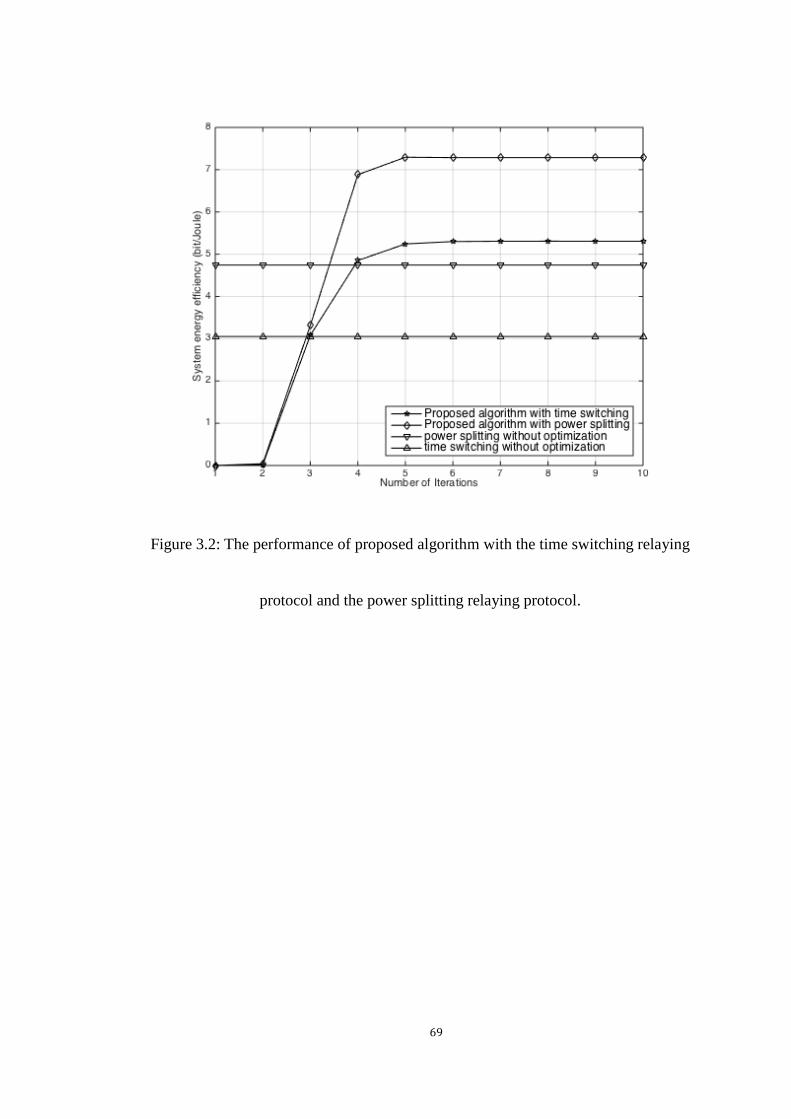
69
Figure 3.2: The performance of proposed algorithm with the time switching relaying
protocol and the power splitting relaying protocol.

70
Figure 3.3: Energy efficiency optimization for the time switching relaying protocol
with different parameters.
Fig. (3.3) and Fig. (3.4) illustrate performances of system energy-efficient
maximization with various noise variances and distances based on the time switching
relaying and power splitting relaying protocol. As can be seen from pictures, the
energy efficiency is deteriorated by the increasing noise variances and distances. The
reason is that when noise variances and distances increase, the channel capacity will
reduce and then lead to the decrease of energy efficiency.
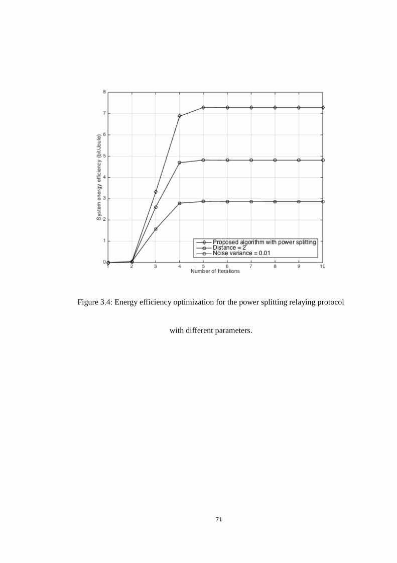
71
Figure 3.4: Energy efficiency optimization for the power splitting relaying protocol
with different parameters.
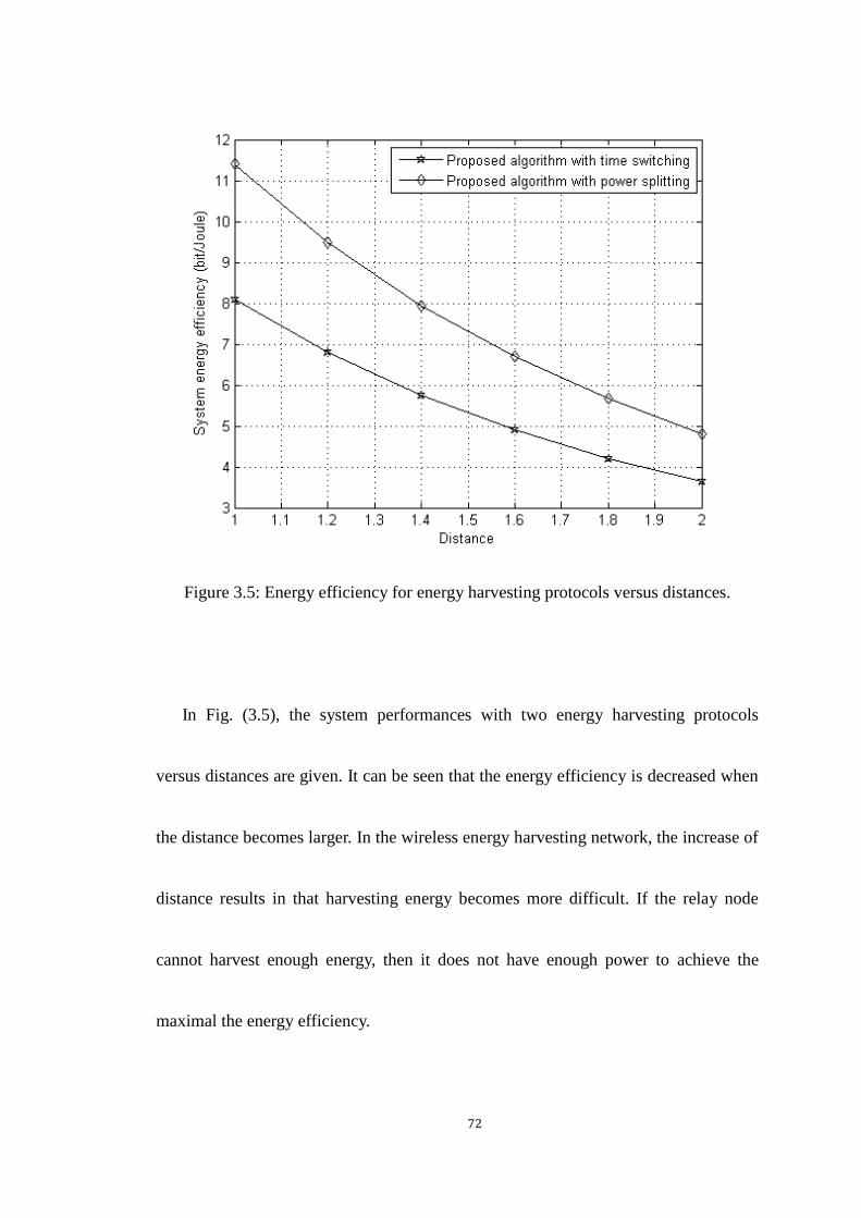
72
Figure 3.5: Energy efficiency for energy harvesting protocols versus distances.
In Fig. (3.5), the system performances with two energy harvesting protocols
versus distances are given. It can be seen that the energy efficiency is decreased when
the distance becomes larger. In the wireless energy harvesting network, the increase of
distance results in that harvesting energy becomes more difficult. If the relay node
cannot harvest enough energy, then it does not have enough power to achieve the
maximal the energy efficiency.

73
3.7 Chapter Summary
This chapter proposed feasible solutions for the maximization of energy efficiency in
cooperative wireless networks based on the time switching relaying protocol and
power splitting relaying protocol. The original problem is first transformed to the
convex form by using nonlinear fractional programming and then is solved by
applying the Lagrange multiplier method. Simulation results confirm the energy
efficiency of the proposed algorithm in the considered model. The trade-off between
energy efficiency and system parameters is also analyzed in the section of numerical
result.

74
Chapter 4
Secure Communication in Cooperative Networks with
Wireless Information and Power Transfer
4.1 Introduction
For the communication network, the issue of security for wireless information and
power transfer is also important, where the passive eavesdropper can potentially
intercept the source transmission due to the openness of wireless channels. There are
many existing works regarding the general physical layer security [76], [77], [78]. In
[76], the overhearing channel can be considered as a degraded one to receive the
information and multiple antennas were used in secure communication systems, where
the secrecy capacity is optimized by carefully designing beamforming. Based on the
study for secrecy rates in SISO fading channels [79], researchers optimized the secure
problem in MISO and MIMO systems [80], [81]. Since the wireless relaying network
can enhance the spectrum efficiency and the physical layer security, the secure

75
optimization in cooperative networks has been studied in [82]. The cooperative
beamforming optimization problem was studied in [83], [84], [85], in which relays use
AF and DF strategies to transmit confidential messages to legitimate receivers.
In this chapter, we study the secrecy rate maximization in the AF wireless
cooperative network with an energy harvesting relay. The authors in [86], [52], [87]
studied the secure issue with simultaneous wireless information and power transfer for
MISO broadcast channels. The secure beamforming at the relay studied in [88]
proposed an iterative algorithm to solve the optimization problem. Motivated by these
works above, we consider the secure issue in a cooperative wireless network in which
the energy harvesting relay harvests energy from RF signals transmitted by the source
and then assist the source in delivering its information to the destination. We
formulate the problem of maximizing the secrecy rate subject to the transmitted power
constraint based on the two different energy harvesting strategies, i.e. the power
splitting relaying protocol and time switching relaying protocol. We solve these
problems by using the SDP relaxation approach and 1-D optimization over the
coefficients of energy harvesting protocols.

76
4.2 System Model
Consider a wireless cooperative relaying network consisting of one source node, one
relay node, one destination node and one eavesdropper node. Except that the relay
node which has 𝑁 antennas, all other nodes are equipped with a single antenna. We
assume that there is no direct link between the source, and the
eavesdropper/destination, i.e. the 𝑁-antenna energy harvesting relay transmits the
source data to the destination node while preventing the eavesdropper from
intercepting source messages. The perfect channel state information is assumed
available at the relay node. It may be feasible for the scenario that the eavesdropper is
also a user in the network but is malicious to overhear the messages from other users.
The considered network is demonstrated in Fig. (4.1).

77
Figure 4.1: System model for energy harvesting cooperative network with one
source-destination pair and one eavesdropper.
The energy harvesting relay can harvest energy from RF signals transmitted by the
source node and utilize the energy as the transmitted power to forward the source
information. In this chapter, we assume the relay node has an initial power and further
collects power from the source node to relay the information; therefore the energy
harvesting technique can further improve the performance [89]. The battery capacity
of the energy harvesting relay is assumed as infinite. The AF scheme is considered in
the cooperative network. The two relaying protocols for energy harvesting are

78
considered in the chapter. A detailed analysis based on the time switching relaying
protocol and the power splitting relaying protocol are given in the following two
sections, respectively. It is assumed that the power consumed in the transmission
circuit at the relay is negligible when it is compared to the transmission power used
for sending the source data to the destination.
4.3 Secrecy Rate Maximization based on Power Splitting
Relaying Protocol
In this section, we study secrecy rate maximization based on the power splitting
relaying protocol. The transmission scheme with power splitting relaying protocol and
the corresponding optimization problem are given as follows.
4.3.1 System Transmission Model and Problem Statement
The energy harvesting relay harvests energy and detects the transmitted signal from
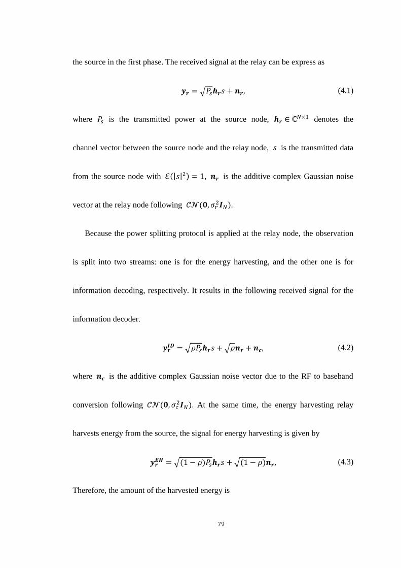
79
the source in the first phase. The received signal at the relay can be express as
𝒚𝒓 = √𝑃𝑠𝒉𝒓𝑠 + 𝒏𝒓, (4.1)
where 𝑃𝑠 is the transmitted power at the source node, 𝒉𝒓 ∈ ℂ𝑁×1 denotes the
channel vector between the source node and the relay node, 𝑠 is the transmitted data
from the source node with ℰ(|𝑠|2) = 1, 𝒏𝒓 is the additive complex Gaussian noise
vector at the relay node following 𝒞𝒩(𝟎, 𝜎𝑟2𝑰𝑁).
Because the power splitting protocol is applied at the relay node, the observation
is split into two streams: one is for the energy harvesting, and the other one is for
information decoding, respectively. It results in the following received signal for the
information decoder.
𝒚𝒓𝑰𝑫 = √𝜌𝑃𝑠𝒉𝒓𝑠 + √𝜌𝒏𝒓 + 𝒏𝒄, (4.2)
where 𝒏𝒄 is the additive complex Gaussian noise vector due to the RF to baseband
conversion following 𝒞𝒩(𝟎, 𝜎𝑐2𝑰𝑁). At the same time, the energy harvesting relay
harvests energy from the source, the signal for energy harvesting is given by
𝒚𝒓𝑬𝑯 = √(1 − 𝜌)𝑃𝑠𝒉𝒓𝑠 + √(1 − 𝜌)𝒏𝒓, (4.3)
Therefore, the amount of the harvested energy is

80
𝐸 =𝜂(1 − 𝜌)(𝑃𝑠‖𝒉𝒓‖
2 + 𝜎𝑟2)𝑇
2, (4.4)
where 𝜂 is the energy conversion efficiency coefficient at the relay. The relay node
has an initial energy 𝐸𝑟𝑖𝑛𝑖 and further harvests energy. Therefore, after the relay is
wirelessly powered by the source with the power splitting relaying protocol, the total
available transmit power at the relay node is expressed as
𝑃𝑟𝑚𝑎𝑥 = 𝜂(1 − 𝜌)(𝑃𝑠‖𝒉𝒓‖
2 + 𝜎𝑟2) + 𝐸𝑟
𝑖𝑛𝑖, (4.5)
Since the energy harvesting relay is operated with the AF protocol, upon receiving
the signal, the relay processes the signal by the relay precoding. The signal transmitted
at the relay node is given by
𝒙𝒓 = √𝜌𝑃𝑠𝑾𝒉𝒓𝑠 + √𝜌𝑾𝒏𝒓 +𝑾𝒏𝒄, (4.6)
where 𝑾 ∈ ℂ𝑁×𝑁 is the precoding matrix, it contains the amplification factor and
also the transmitted power. The power of 𝑥𝑟 at the relay node is
𝑃𝑟 = 𝜌𝑃𝑠‖𝑾𝒉𝒓‖2 + 𝜌𝜎𝑟
2‖𝑾‖2 + 𝜎𝑐2‖𝑾‖2, (4.7)
Then the received signal at the destination node in the second phase is given by
𝑦𝑑 = √𝜌𝑃𝑠𝒉𝒅𝑇𝑾𝒉𝒓𝑠 + √𝜌𝒉𝒅
𝑇𝑾𝒏𝒓 + 𝒉𝒅𝑇𝑾𝒏𝒄 + 𝑛𝑑 , (4.8)
where 𝒉𝒅 ∈ ℂ𝑁×1 denotes the channel vector between the relay node and the

81
destination node and 𝑛𝑑 is the additive Gaussian noise at the destination following
𝒞𝒩(0, 𝜎𝑑2). Similarly, the received signal at the eavesdropper can be written as
𝑦𝑒 = √𝜌𝑃𝑠𝒉𝒆𝑇𝑾𝒉𝒓𝑠 + √𝜌𝒉𝒆
𝑇𝑾𝒏𝒓 + 𝒉𝒆𝑇𝑾𝒏𝒄 + 𝑛𝑒 , (4.9)
where 𝒉𝒆 ∈ ℂ𝑁×1 denotes the channel vector between the relay node and the
destination node, and 𝑛𝑒 is the additive Gaussian noise at the destination following
𝒞𝒩(0, 𝜎𝑒2).
According to the aforementioned signal model, the received SNRs at the
destination node and the eavesdropper node are
𝑆𝑁𝑅𝑑 =𝜌𝑃𝑠|𝒉𝒅
𝑇𝑾𝒉𝒓|2
𝜌𝜎𝑟2‖𝒉𝒅𝑇𝑾‖
2+ 𝜎𝑐2‖𝒉𝒅
𝑇𝑾‖2+ 𝜎𝑑
2, (4.10)
and
𝑆𝑁𝑅𝑒 =𝜌𝑃𝑠|𝒉𝒆
𝑇𝑾𝒉𝒓|2
𝜌𝜎𝑟2‖𝒉𝒆𝑇𝑾‖
2+ 𝜎𝑐2‖𝒉𝒆
𝑇𝑾‖2+ 𝜎𝑒2
, (4.11)
respectively.
The achievable secrecy rate can be presented as
𝑅𝑠 = |1
2log2(1 + 𝑆𝑁𝑅𝑑) −
1
2log2(1 + 𝑆𝑁𝑅𝑒)|
+
, (4.12)
In this chapter, we formulate the problem for maximizing the secrecy rate subject
to the transmitted power constraint at the relay node via jointly optimizing relay

82
precoding and the power splitting coefficient. Particularly, the addressed optimization
problem is formulated as follows
max𝑾,𝜌
𝑅𝑠
𝑠. 𝑡. 𝐶1:𝑃𝑟 ≤ 𝑃𝑟𝑚𝑎𝑥,
𝐶2:0 ≤ 𝜌 ≤ 1. (4.13)
It is obvious that the problem stated above is not a standard convex problem because
the objective function is non-concave and the power splitting coefficient results in the
problem being not convex. In the next subsection, we find the solution to this
problem.
It is noted that in the 𝐶1, the transmitted power at the relay node may not use the
total available power from the energy harvesting and this may results in that there will
be the leftover of energy at the relay node stored for the next block time. However, in
the simulation, the relay node always uses the total available at the relay node to
maximize the secrecy rate, so the above concern does not exist in this optimization
problem.
83
4.3.2 The Optimal Solution
In this subsection, we proposed an optimal solution based on SDP relaxation. Firstly
we introduce a new variable 𝛾𝑒 to represent the predefined threshold for the
eavesdropper’s SNR. 𝛾𝑒 denotes the maximum tolerable SINR at the eavesdropper,
which is practically much less than the SINR at the desired destination node to ensure
the secure communication. After we introduce 𝛾𝑒 , if the transformed problem is
solvable, it is guaranteed that the secrecy capacity is larger than 0. Although 𝛾𝑒 is not
the optimization variable in our problem, the optimal solution of the transformed
problem is close to the original problem if the value of 𝛾𝑒 is suitable. The original
problem is reformulated as follows:
max𝑾,𝜌
𝑆𝑁𝑅𝑑
𝑠. 𝑡. 𝐶1:𝑆𝑁𝑅𝑒 ≤ 𝛾𝑒 ,
𝐶2:𝑃𝑟 ≤ 𝑃𝑟𝑚𝑎𝑥 ,
𝐶3:0 ≤ 𝜌 ≤ 1. (4.14)
The new obtained problem is still not a convex problem. We further transform the
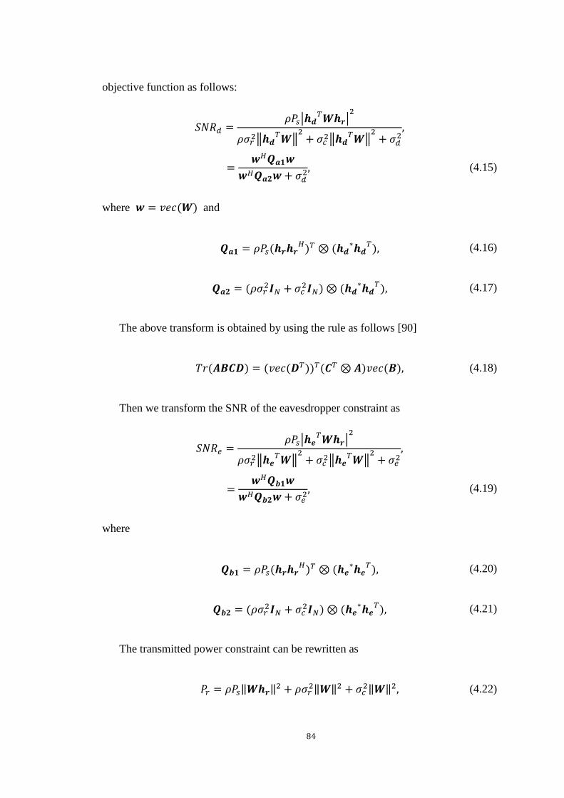
84
objective function as follows:
𝑆𝑁𝑅𝑑 =𝜌𝑃𝑠|𝒉𝒅
𝑇𝑾𝒉𝒓|2
𝜌𝜎𝑟2‖𝒉𝒅𝑇𝑾‖
2+ 𝜎𝑐2‖𝒉𝒅
𝑇𝑾‖2+ 𝜎𝑑
2,
=𝒘𝐻𝑸𝒂𝟏𝒘
𝒘𝐻𝑸𝒂𝟐𝒘+ 𝜎𝑑2, (4.15)
where 𝒘 = 𝑣𝑒𝑐(𝑾) and
𝑸𝒂𝟏 = 𝜌𝑃𝑠(𝒉𝒓𝒉𝒓𝐻)𝑇 ⊗ (𝒉𝒅
∗𝒉𝒅𝑇), (4.16)
𝑸𝒂𝟐 = (𝜌𝜎𝑟2𝑰𝑁 + 𝜎𝑐
2𝑰𝑁) ⊗ (𝒉𝒅∗𝒉𝒅
𝑇), (4.17)
The above transform is obtained by using the rule as follows [90]
𝑇𝑟(𝑨𝑩𝑪𝑫) = (𝑣𝑒𝑐(𝑫𝑇))𝑇(𝑪𝑇 ⊗𝑨)𝑣𝑒𝑐(𝑩), (4.18)
Then we transform the SNR of the eavesdropper constraint as
𝑆𝑁𝑅𝑒 =𝜌𝑃𝑠|𝒉𝒆
𝑇𝑾𝒉𝒓|2
𝜌𝜎𝑟2‖𝒉𝒆𝑇𝑾‖
2+ 𝜎𝑐2‖𝒉𝒆
𝑇𝑾‖2+ 𝜎𝑒2
,
=𝒘𝐻𝑸𝒃𝟏𝒘
𝒘𝐻𝑸𝒃𝟐𝒘+ 𝜎𝑒2, (4.19)
where
𝑸𝒃𝟏 = 𝜌𝑃𝑠(𝒉𝒓𝒉𝒓𝐻)𝑇 ⊗ (𝒉𝒆
∗𝒉𝒆𝑇), (4.20)
𝑸𝒃𝟐 = (𝜌𝜎𝑟2𝑰𝑁 + 𝜎𝑐
2𝑰𝑁) ⊗ (𝒉𝒆∗𝒉𝒆
𝑇), (4.21)
The transmitted power constraint can be rewritten as
𝑃𝑟 = 𝜌𝑃𝑠‖𝑾𝒉𝒓‖2 + 𝜌𝜎𝑟
2‖𝑾‖2 + 𝜎𝑐2‖𝑾‖2, (4.22)
85
= 𝒘𝐻𝑸𝒄𝒘,
where
𝑸𝒄 = (𝜌𝑃𝑠𝒉𝒓𝒉𝒓𝐻 + 𝜌𝜎𝑟
2𝑰𝑁 + 𝜎𝑐2𝑰𝑁) ⊗ 𝑰𝑁 , (4.23)
Define a new variable 𝑿 = 𝒘𝒘𝐻, the optimization problem can be reformulated
as
max𝑿≽𝟎,𝜌
𝑇𝑟(𝑸𝒂𝟏𝑿)
𝑇𝑟(𝑸𝒂𝟐𝑿) + 𝜎𝑑2
𝑠. 𝑡. 𝐶1:𝑇𝑟(𝑸𝒃𝟏𝑿)
𝑇𝑟(𝑸𝒃𝟐𝑿) + 𝜎𝑒2≤ 𝛾𝑒 ,
𝐶2:𝑇𝑟(𝑸𝒄𝑿) ≤ 𝑃𝑟𝑚𝑎𝑥,
𝐶3:0 ≤ 𝜌 ≤ 1,
𝐶4: 𝑅𝑎𝑛𝑘(𝑿) = 1. (4.24)
It can be seen that the rank-one constraint makes the problem still difficult to solve.
Therefore, we drop the rank-one constraint and a SDP problem can be obtained as
max𝑿≽𝟎,𝜌
𝑇𝑟(𝑸𝒂𝟏𝑿)
𝑇𝑟(𝑸𝒂𝟐𝑿) + 𝜎𝑑2
𝑠. 𝑡. 𝐶1:𝑇𝑟(𝑸𝒃𝟏𝟐𝑿) ≤ 𝜎𝑒2,
𝐶2:𝑇𝑟(𝑸𝒄𝑿) ≤ 𝑃𝑟𝑚𝑎𝑥,
𝐶3:0 ≤ 𝜌 ≤ 1. (4.25)

86
where 𝑸𝒃𝟏𝟐 =𝟏
𝛾𝑒𝑸𝒃𝟏 − 𝑸𝒃𝟐. It is worthy to point out that it is still challenging to
solve this problem directly, mainly due to the power splitting coefficient in the
problem, which renders the joint optimization problem unsolvable. To tackle this
difficulty, we perform 1-D optimization over the power splitting coefficient. Then we
can select the best performance among those possible choices of the power splitting
coefficient. If the value of 𝜌 is set, the problem can be treated as a quasi-convex SDP
problem. Instead of employing the bisection search approach, we use the
Charnes-Cooper transformation [91] to solve it. Specifically, we define a new variable
𝑡 =1
𝑇𝑟(𝑸𝒂𝟐𝑿)+𝜎𝑑2 and let �̃� = 𝑡𝑿. The problem can be recast as follows
max�̃�≽𝟎,𝑡
𝑇𝑟(𝑸𝒂𝟏�̃�)
𝑠. 𝑡. 𝐶1:𝑇𝑟(𝑸𝒂𝟐�̃�) + 𝑡𝜎𝑑2 = 1,
𝐶2:𝑇𝑟(𝑸𝒃𝟏𝟐�̃�) ≤ 𝑡𝜎𝑒2,
𝐶3:𝑇𝑟(𝑸𝒄�̃�) ≤ 𝑡𝑃𝑟𝑚𝑎𝑥 . (4.26)
Then the problem is a standard SDP problem, and one can efficiently find its
global optimal solution via available solvers [92]. The optimal solution is supposed as
�̃�∗, 𝑡∗. Then the optimal solution of 𝑿 denoted by 𝑿∗ is obtained by 𝑿∗ =�̃�∗
𝑡∗ . If

87
the rank of �̃�∗ is one, 𝒘 is exactly calculated via the eigenvalue decomposition.
Otherwise, we can employ the following theorem which is obtained from the result in
[93] to obtain the rank-one solution.
Theorem 1. For a matrix �̃�∗ which has a higher rank, the rank-one solution can be
acquired via the follow procedure.
Table 4.1: SBP rank reduction procedure
1. Decompose �̃�∗ as �̃�∗ = 𝑽𝑽𝐻 with 𝑽 ∈ ℂ𝑁2×𝑟, where 𝑟 is the rank of �̃�∗.
2. Find a nonzero 𝑟 × 𝑟 Hermitian matrix 𝑴 to satisfy the equations as follows
𝑇𝑟(𝑽𝐻𝑸𝒂𝟐𝑽𝑴) = 0, 𝑇𝑟(𝑽𝐻𝑸𝒃𝟏𝟐𝑽𝑴) = 0 and 𝑇𝑟(𝑽𝐻𝑸𝒄𝑽𝑴) = 0.
3. Evaluate all eigenvalues 𝜆1, 𝜆2 … 𝜆𝑟 for matrix 𝑴 and define |𝜆| =
max{|𝜆1|, |𝜆2| … |𝜆𝑟|}, where |𝜆| represents the modulus of 𝜆.
4. Update matrix �̃�∗ = 𝑽(𝑰𝑟 −1
𝜆𝑴)𝑽𝐻. If �̃�∗ still has the higher rank, we repeat the
step 1-3 until the rank of �̃�∗ is one.
Proof. The proof steps are similar to the ones in [93], [94]. Since there are three linear

88
equations in Step 2, we can always find a nonzero solution 𝑴 if 𝑟2 ≥ 3. It is can be
found that the rank of �̃�∗ is reduced at least one by performing one iteration. And the
updated �̃�∗ in step 4 satisfies equations in step 2, which is also a solution for the SDP
problem, i.e. the updated �̃�∗ can achieve the same value of the objective function for
our transformed problem but with the lower rank. We can finally acquire a rank-one
solution by repeating the procedure. The proof is completed. ∎
Remark 1. In step 2 of Theorem 1, we need to solve an undetermined system of linear
equations to find 𝑴. There are three equations and 𝑟2 real-valued unknowns. If
𝑟2 ≥ 3, then it can be found a nonzero solution for linear equations. We can rewrite
the system of linear equations into the form 𝑨𝒙 = 0, where 𝑨 ∈ ℝ3×𝑟2 and 𝒙 ∈ ℝ𝑟2.
The matrix 𝑨 is the combination of the matrix 𝑽𝐻𝑸𝒂𝟐𝑽, 𝑽𝐻𝑸𝒃𝟏𝟐𝑽 and 𝑽𝐻𝑸𝒄𝑽.
Then finding a nonzero 𝒙 is equal to finding the null space of 𝑨. Recall that 𝑴 ∈
ℝ𝑟×𝑟, after reshaping 𝒙, 𝑴 is obtained.
Remark 2. The rank of �̃�∗ will be reduced at least one by performing Theorem 1 one

89
time. The number of iterations depends on the initial rank of �̃�∗. For example, if the
initial rank of �̃�∗ is 9, at worst we need to perform Theorem 1 eight times.
4.4 Secrecy Rate Maximization based on Time Switching
Relaying Protocol
In this section, we study the secrecy rate maximization problem on the basis of time
switching relaying protocol. The transmission model with the time switching relaying
protocol and the corresponding optimization problem are given as follows.
4.4.1 System Transmission Model and Problem Statement
The received signal at the relay can be expressed as follows
𝒚𝒓 = √𝑃𝑠𝒉𝒓𝑠 + 𝒏𝒓 + 𝒏𝒄, (4.27)
where 𝑃𝑠, 𝒉𝒓, 𝑠, 𝒏𝒓 and 𝒏𝒄 have the same definition as previously.
The relay harvests energy from RF signals sent by the source for 𝛼 time, and the

90
amount of the harvested energy is given by
𝐸 = 𝜂𝛼(𝑃𝑠‖𝒉𝒓‖2 + 𝜎𝑟
2)𝑇, (4.28)
The total available transmit power at the relay is then expressed as follows
𝑃𝑟𝑚𝑎𝑥 =
2𝜂𝛼(𝑃𝑠‖𝒉𝒓‖2 + 𝜎𝑟
2)
1 − 𝛼+ 𝐸𝑟
𝑖𝑛𝑖, (4.29)
Since the energy harvesting relay is operated with the AF protocol, the signal
transmitted by the relay node can be written as follows
𝒙𝒓 = √𝑃𝑠𝑾𝒉𝒓𝑠 +𝑾𝒏𝒓 +𝑾𝒏𝒄, (4.30)
The relay transmission power is given by
𝑃𝑟 = 𝑃𝑠‖𝑾𝒉𝒓‖2 + 𝜎𝑟
2‖𝑾‖2 + 𝜎𝑐2‖𝑾‖2, (4.31)
Then the received signal at the destination node is given by
𝑦𝑑 = √𝑃𝑠𝒉𝒅𝑇𝑾𝒉𝒓𝑠 + 𝒉𝒅
𝑇𝑾𝒏𝒓 + 𝒉𝒅𝑇𝑾𝒏𝒄 + 𝑛𝑑 , (4.32)
Similarly, the received signal at the eavesdropper can be written as follows
𝑦𝑒 = √𝑃𝑠𝒉𝒆𝑇𝑾𝒉𝒓𝑠 + 𝒉𝒆
𝑇𝑾𝒏𝒓 + 𝒉𝒆𝑇𝑾𝒏𝒄 + 𝑛𝑒 , (4.33)
According to the described signal model, the received SNRs at the destination
node and the eavesdropper node are
𝑆𝑁𝑅𝑑 =𝑃𝑠|𝒉𝒅
𝑇𝑾𝒉𝒓|2
𝜎𝑟2‖𝒉𝒅𝑇𝑾‖
2+ 𝜎𝑐2‖𝒉𝒅
𝑇𝑾‖2+ 𝜎𝑑
2, (4.34)

91
and
𝑆𝑁𝑅𝑒 =𝑃𝑠|𝒉𝒆
𝑇𝑾𝒉𝒓|2
𝜎𝑟2‖𝒉𝒆𝑇𝑾‖
2+ 𝜎𝑐2‖𝒉𝒆
𝑇𝑾‖2+ 𝜎𝑒2
, (4.35)
respectively. The achievable secrecy rate with the time switching relaying protocol
can be expressed as
𝑅𝑠 = |1 − 𝛼
2log2(1 + 𝑆𝑁𝑅𝑑) −
1 − 𝛼
2log2(1 + 𝑆𝑁𝑅𝑒)|
+
, (4.36)
We formulate the problem of maximizing the secrecy rate subject to the
transmitted power constraint at the relay node, via jointly optimizing relay precoding
and the time switching coefficient. The optimization problem is formulated as follows
max𝑾,𝛼
𝑅𝑠
𝑠. 𝑡. 𝐶1:𝑃𝑟 ≤ 𝑃𝑟𝑚𝑎𝑥,
𝐶2:0 ≤ 𝛼 ≤ 1. (4.37)
This problem is in a form similar to the one proposed in the previous section, and also
not a standard convex problem. We can perform similar transform steps to make the
problem solvable.

92
4.4.2. The Optimal Solution
Firstly we introduce a new variable 𝛾𝑒 to represent the predefined threshold for the
eavesdropper’s SNR and reformulate the original problem as follows
max𝑾,𝛼
𝑆𝑁𝑅𝑑
𝑠. 𝑡. 𝐶1:𝑆𝑁𝑅𝑒 ≤ 𝛾𝑒 ,
𝐶2:𝑃𝑟 ≤ 𝑃𝑟𝑚𝑎𝑥 ,
𝐶3:0 ≤ 𝛼 ≤ 1. (4.37)
Then we further transform the objective function as follows
𝑆𝑁𝑅𝑑 =𝑃𝑠|𝒉𝒅
𝑇𝑾𝒉𝒓|2
𝜎𝑟2‖𝒉𝒅𝑇𝑾‖
2+ 𝜎𝑐2‖𝒉𝒅
𝑇𝑾‖2+ 𝜎𝑑
2,
=𝒘𝐻𝑸𝒂𝟏𝒘
𝒘𝐻𝑸𝒂𝟐𝒘+ 𝜎𝑑2, (4.38)
where
𝑸𝒂𝟏 = 𝑃𝑠(𝒉𝒓𝒉𝒓𝐻)𝑇 ⊗ (𝒉𝒅
∗𝒉𝒅𝑇), (4.39)
𝑸𝒂𝟐 = (𝜎𝑟2𝑰𝑁 + 𝜎𝑐
2𝑰𝑁) ⊗ (𝒉𝒅∗𝒉𝒅
𝑇), (4.40)
The SNR of the eavesdropper constraint is given by
𝑆𝑁𝑅𝑒 =𝑃𝑠|𝒉𝒆
𝑇𝑾𝒉𝒓|2
𝜎𝑟2‖𝒉𝒆𝑇𝑾‖
2+ 𝜎𝑐2‖𝒉𝒆
𝑇𝑾‖2+ 𝜎𝑒2
, (4.41)
93
=𝒘𝐻𝑸𝒃𝟏𝒘
𝒘𝐻𝑸𝒃𝟐𝒘+ 𝜎𝑒2,
where
𝑸𝒃𝟏 = 𝑃𝑠(𝒉𝒓𝒉𝒓𝐻)𝑇 ⊗ (𝒉𝒆
∗𝒉𝒆𝑇), (4.42)
𝑸𝒃𝟐 = (𝜎𝑟2𝑰𝑁 + 𝜎𝑐
2𝑰𝑁) ⊗ (𝒉𝒆∗𝒉𝒆
𝑇), (4.43)
The transmitted power constraint can be rewritten as follows
𝑃𝑟 = 𝑃𝑠‖𝑾𝒉𝒓‖2 + 𝜎𝑟
2‖𝑾‖2 + 𝜎𝑐2‖𝑾‖2,
= 𝒘𝐻𝑸𝒄𝒘, (4.44)
where
𝑸𝒄 = (𝑃𝑠𝒉𝒓𝒉𝒓𝐻 + 𝜎𝑟
2𝑰𝑁 + 𝜎𝑐2𝑰𝑁) ⊗ 𝑰𝑁 , (4.45)
Define 𝑿 = 𝒘𝒘𝐻, and the optimization problem can be reformulated as follows
max𝑿≽𝟎,𝛼
𝑇𝑟(𝑸𝒂𝟏𝑿)
𝑇𝑟(𝑸𝒂𝟐𝑿) + 𝜎𝑑2
𝑠. 𝑡. 𝐶1:𝑇𝑟(𝑸𝒃𝟏𝑿)
𝑇𝑟(𝑸𝒃𝟐𝑿) + 𝜎𝑒2≤ 𝛾𝑒 ,
𝐶2:𝑇𝑟(𝑸𝒄𝑿) ≤ 𝑃𝑟𝑚𝑎𝑥,
𝐶3:0 ≤ 𝛼 ≤ 1,
𝐶4: 𝑅𝑎𝑛𝑘(𝑿) = 1. (4.46)
We drop the rank-one constraint and a SDP problem can be obtained as follows

94
max𝑿≽𝟎,𝛼
𝑇𝑟(𝑸𝒂𝟏𝑿)
𝑇𝑟(𝑸𝒂𝟐𝑿) + 𝜎𝑑2
𝑠. 𝑡. 𝐶1:𝑇𝑟(𝑸𝒃𝟏𝟐𝑿) ≤ 𝜎𝑒2,
𝐶2:𝑇𝑟(𝑸𝒄𝑿) ≤ 𝑃𝑟𝑚𝑎𝑥,
𝐶3:0 ≤ 𝛼 ≤ 1. (4.47)
where 𝑸𝒃𝟏𝟐 =𝟏
𝛾𝑒𝑸𝒃𝟏 − 𝑸𝒃𝟐. The time switching coefficient is still a challenge to be
optimized. We again perform 1-D optimization over the time switching coefficient. If
the value of 𝛼 is set, the problem can be treated as a quasi-convex SDP problem. We
also use the Charnes-Cooper transformation. Define a new variable 𝑡 =1
𝑇𝑟(𝑸𝒂𝟐𝑿)+𝜎𝑑2
and let �̃� = 𝑡𝑿. The problem can be recast as follows
max�̃�≽𝟎,𝑡
𝑇𝑟(𝑸𝒂𝟏�̃�)
𝑠. 𝑡. 𝐶1:𝑇𝑟(𝑸𝒂𝟐�̃�) + 𝑡𝜎𝑑2 = 1,
𝐶2:𝑇𝑟(𝑸𝒃𝟏𝟐�̃�) ≤ 𝑡𝜎𝑒2,
𝐶3:𝑇𝑟(𝑸𝒄�̃�) ≤ 𝑡𝑃𝑟𝑚𝑎𝑥 . (4.48)
Then the problem is solvable like the problem with power splitting relaying
protocol. The optimal solution is denoted by �̃�∗, 𝑡∗. Then the solution of 𝑿 denoted
by 𝑿∗ is obtained by 𝑿∗ =�̃�∗
𝑡∗ . If the rank of �̃�∗ is not one, we can employ

95
Theorem 1 to obtain the rank-one solution.
4.5 Numerical Results
In this section, simulation results are provided to evaluate the performance of the
proposed secrecy rate optimization solution. The number of antenna is 3. We use the
TGn path loss model with the directional transceiver antenna gain of 10 dBi. The
distance between each node is set as 10 m. The carrier frequency is 470 MHz, which
is accorded with the IEEE 802.11af Wi-Fi parameters [95]. The noise variance is
assumed as 𝜎𝑟2 = 𝜎𝑐
2 = 𝜎𝑑2 = 𝜎𝑒
2 = 𝜎 = −25 dBm. The initial power at the relay
node is 10 dBm. The energy conversion efficient is 0.8. The channel vectors are
randomly generated from independent and identically distributed Rayleigh Rician
random variables with Rician factor 6dB. The maximum SNR tolerance for the
eavesdropper is assumed as −10 dB. Simulation results were averaged over 1000
independent trials.

96
Figure 4.2: Secrecy rate versus transmitted power at the source node for the proposed
schemes with energy harvesting protocols.
In Fig. (4.2), the secrecy rates achieved by different secure transmission schemes
versus the transmitted power of the source are plotted. The results for power splitting
relaying and time switching relaying schemes are obtained with its optimal energy
harvesting coefficient, ρ = 0.5 and α = 0.3. It can be seen that curves of secrecy
rates for the two proposed energy harvesting schemes are monotonically
non-decreasing functions of the transmitted power because the higher transmitted

97
power results in more available power at the relay for the relay-destination
transmission. The proposed scheme with power splitting relaying protocol
outperforms that with the time switching relaying protocol. For comparison, Fig. (4.2)
also presents the performance for non-energy harvesting cooperative networks. In the
non-energy harvesting scheme, the relay node only uses its initial power to relay the
information. It can be observed that performances of two energy harvesting schemes
and the non-energy scheme are close in the low source power region. This is because
that if the transmitted power at the source node is small, the energy harvesting relay
can not collect much power to improve the system performance. However, if the
source transmitted power is large enough, the energy harvesting schemes can
obviously outperform the non-energy harvesting scheme. The secrecy rate in the
non-energy harvesting scheme is limited by the relay power and can not further be
improved with the increased source power. From the figure, we can see that the energy
harvesting relaying schemes have better performance than the non-energy harvesting
scheme, which demonstrates that energy harvesting relay schemes can improve the
secrecy rate in a resource-limited relay network context.

98
Figure 4.3: Secrecy rate versus transmitted power at the source node for the power
splitting relaying protocol with different choices of system parameters.

99
Figure 4.4: Secrecy rate versus transmitted power at the source node for the time
switching relaying protocol with different choices of system parameters.
In Fig. (4.3) and Fig. (4.4), we present the secrecy rate versus the transmitted
power for the proposed scheme with power splitting relaying and time switching
relaying protocols by using different system parameters. It can be seen from the figure
that the secrecy rates achieved by these two protocols improve with the increased
number of the antenna and are degraded with the increase of the distance between
each node. This is attributed to the fact that the relay could exploit the array gain to

100
achieve better performance with more antennas, and the longer distance makes
channel attenuation larger in turns resulting in, the worse performance of relay
networks.
4.6 Chapter Summary
In this chapter, we formulated the secrecy rate maximization in an AF relay network
with power splitting relaying and time switching relaying energy harvesting protocols
while taking into account relay precoding and the energy harvesting coefficient. The
optimal solution was found by applying the SDP relaxation approach and 1-D
optimization. Simulation results illustrated the energy harvesting relaying schemes
could enhance the secrecy rate in a resource-limited relay network and analyzed the
trade-off between the secrecy rate and system parameters.

101
Chapter 5
Beamforming Optimization in Energy Harvesting
Cooperative Full-Duplex Networks with Self-Energy
Recycling Protocol
5.1 Introduction
Many works regarding the energy harvesting cooperative network considered the
half-duplex network model; however, the full-duplex model is another research
interest in the wireless energy harvesting study. The authors in [96], [97] studied the
full-duplex wireless powered network with the time switching protocol. Due to the
full-duplex structure, the node could transmit energy and receive information
simultaneously. The authors in [98] proposed a self-energy recycling protocol. In [98],
a full-duplex energy harvesting relay node is equipped with two groups of the antenna.
In the first transmission phase, the relay node uses its receiving antenna to receive the

102
information from the source node. In the second transmission phase, the relay node
uses its receiving antenna to collect the power transmitted from the source node and
uses its transmission antennas to send the information to the destination node. During
the second phase, the energy harvesting relay not only collects the power from the
source node but also recycles part of its transmitted power from its loop-back channel.
The authors in [98] set up this self-energy recycling protocol in a MISO relaying
channel.
Motivated by this, we study the beamforming optimization problem based on the
self-energy recycling relaying protocol in a cooperative wireless network. We
modeled a wireless energy harvesting cooperative network with a self-energy
recycling relay. The relay node is equipped two groups of the antenna, so it is capable
of collecting the information or energy and relaying the information simultaneously.
In this model, we formulated the beamforming optimization problem for maximizing
the achievable rate subject to the available transmitted power at the relay node and we
used the SDP relaxation approach to solve it. To highlight the advantage of the
self-energy recycling scheme, we also provided the solution for the beamforming

103
optimization problem with the time switching relaying protocol and the power
splitting relaying protocol. Simulation results are provided to verify that the
self-energy recycling relaying protocol achieves an obvious rate gain compared to the
time switching relaying protocol or power splitting relaying protocol. The trade-off
between the achievable rate and system parameters is also analyzed.
5.2 System Model
The cooperative wireless network considered here includes one source-destination
pair and one energy harvesting relay. The source node and the destination node are
equipped one antenna respectively. The relay node has two groups of the RF chains;
one is used for the information transmission while the other one is used for receiving.
The number of transmission antennas 𝑁𝑡 and the number of receiving antennas 𝑁𝑟
are the same, i.e. 𝑁𝑡 = 𝑁𝑟 = 𝑁. We assume that there is no direct link between the
source node and the destination node, i.e. the source node intends to transmit the
message to the destination node with the assist of the relay node. Channels are
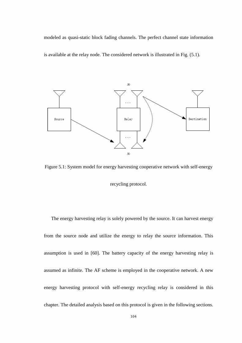
104
modeled as quasi-static block fading channels. The perfect channel state information
is available at the relay node. The considered network is illustrated in Fig. (5.1).
Figure 5.1: System model for energy harvesting cooperative network with self-energy
recycling protocol.
The energy harvesting relay is solely powered by the source. It can harvest energy
from the source node and utilize the energy to relay the source information. This
assumption is used in [60]. The battery capacity of the energy harvesting relay is
assumed as infinite. The AF scheme is employed in the cooperative network. A new
energy harvesting protocol with self-energy recycling relay is considered in this
chapter. The detailed analysis based on this protocol is given in the following sections.

105
We also assume that the relay node itself has the limited power to support its circuitry
power consumption; however, the relay node does not use its power to relay the
information. Therefore, the relay node needs to be wirelessly powered by the source
node.
5.3 Beamforming with Self-Energy Recycling Relay
In this section, we study the relay beamforming optimization problem in the
self-energy recycling relaying network. The transmission model is given as follows.
5.3.1 Relay Protocol and Transmission Model
The whole transmission process is operated in the block time, denoted by 𝑇. The
information transmission process is split into two phases. In the first phase, the source
transmits information to the relay for 𝑇
2 time, and relay uses its receiving antennas to
receive information. In the second phase, the source node transmits RF signals to

106
power the energy harvesting relay and the relay sends the amplified information to the
destination. The energy harvesting relay is equipped with one group of the
transmission antenna and one group of receiving antenna. The receiving antennas at
the relay node harvest energy and use the harvested energy to assist transmission
antennas to relay information. It is noted that the full-duplex relay node needs some
time to harvest energy and then relay information, therefore there is delay between
these two procedures. However the delay could be very small and is ignored in this
work.
The energy harvesting relay first receives the information from the source node
with its receiving antennas. The received signal at the relay can be expressed as
𝒚𝒓𝟏 = √𝑃𝑠𝒉𝒓𝑥𝑠 + 𝒏𝒓𝟏, (5.1)
where 𝑃𝑠 is the transmitted power, 𝒉𝒓 ∈ ℂ𝑁×1 is the channel vector from the source
to receiving antennas of the relay, and 𝑥𝑠 is the transmitted data from the source node
with ℰ(|𝑥𝑠|2) = 1 and 𝒏𝒓𝟏 is the additive complex Gaussian noise vector at the
relay node following 𝒞𝒩(𝟎, 𝜎𝑟12 𝑰𝑁).
Since the energy harvesting relay is operated with the AF protocol, upon receiving

107
the signal, the relay processes the signal by the relay precoding. The signal transmitted
by the relay node is given by
𝒙𝒓 = √𝑃𝑠𝑾𝒉𝒓𝑥𝑠 +𝑾𝒏𝒓𝟏, (5.2)
where 𝑾 ∈ ℂ𝑁×𝑁 is the precoding matrix. The power of the transmitted signal from
the relay is
𝑃𝑟 = 𝑃𝑠‖𝑾𝒉𝒓‖2 + 𝜎𝑟1
2 ‖𝑾‖2, (5.3)
In the second phase, the relay uses its transmission antennas to relay the
information to the destination node. The received signal at the destination is given by
𝑦𝑑 = √𝑃𝑠𝒉𝒅𝐻𝑾𝒉𝒓𝑥𝑠 + 𝒉𝒅
𝐻𝑾𝒏𝒓𝟏 + 𝑛𝑑 , (5.4)
where 𝒉𝒅 ∈ ℂ𝑁×1 is the channel vector between the transmission antennas of the
relay and the destination node and 𝑛𝑑 is additive Gaussian noise at the destination
following 𝒞𝒩(0, 𝜎𝑑2) . Concurrently, the energy harvesting relay is wirelessly
powered by the source node with the dedicated energy-bearing signal. The received
signal at the relay is
𝑦𝑟2 = √𝑃𝑠𝒉𝒓𝑥𝑒 +𝑯𝒓𝑥𝑟 + 𝒏𝒓𝟐,
= √𝑃𝑠𝒉𝒓𝑥𝑒 +√𝑃𝑠𝑯𝒓𝑾𝒉𝒓𝑥𝑠 +𝑯𝒓𝑾𝒏𝒓𝟏 + 𝒏𝒓𝟐, (5.5)

108
where 𝑥𝑒 is the transmitted signal from the source node with ℰ(|𝑥𝑒|2) = 1, 𝑯𝒓 ∈
ℂ𝑁×𝑁 is the channel matrix of the loop channel at the relay node and 𝒏𝒓𝟐 is the
received additive complex Gaussian noise vector following 𝒞𝒩(0, 𝜎𝑟22 𝑰𝑁). The relay
node not only collects energy from the source node but also recycles part of its
transmitted power due to its two groups of antennas being activated at the same time.
Unlike the other full-duplex relaying studies, the relay node employs interference
cancellation techniques to eliminate the loop-back interference signal. In the energy
harvesting cooperative relaying network, the loop-back signal can be reused at the
relay as the transmitted power. The amount of the harvested energy is given by
𝐸 =𝜂𝑇
2(𝑃𝑠‖𝒉𝒓‖
2 + 𝑃𝑠‖𝑯𝒓𝑾𝒉𝒓‖2 + 𝜎𝑟1
2 ‖𝑯𝒓𝑾‖2 + 𝜎𝑟22 ), (5.6)
where 𝜂 is the energy conversion efficiency coefficient at the relay. Then the total
available transmitted power at the relay node is 𝐸
𝑇 2⁄ which can be expressed as
𝑃𝑟𝑚𝑎𝑥 = 𝜂(𝑃𝑠‖𝒉𝒓‖
2 + 𝑃𝑠‖𝑯𝒓𝑾𝒉𝒓‖2 + 𝜎𝑟1
2 ‖𝑯𝒓𝑾‖2 + 𝜎𝑟22 ), (5.7)
According to the aforementioned signal model, the received SNR at the
destination node is
𝑆𝑁𝑅𝑑 =𝑃𝑠|𝒉𝒅
𝐻𝑾𝒉𝒓|2
𝜎𝑟12 ‖𝒉𝒅
𝐻𝑾‖2+ 𝜎𝑑
2, (5.8)

109
The achievable rate can be presented as
𝑅 =1
2log2(1 + 𝑆𝑁𝑅𝑑), (5.9)
5.3.2 Problem Formulation and Beamforming Design
In this section, we consider the beamforming optimization problem for the considered
network. We formulate the problem to maximize the achievable rate subject to the
transmitted power constraint at the relay node. Particularly, the addressed
optimization problem is formulated as follows
max𝑾
𝑅
𝑠. 𝑡. 𝑃𝑟 ≤ 𝑃𝑟𝑚𝑎𝑥 . (5.10)
It is noted that in the constraint, the transmitted power at the relay node may not
use the total available power from the energy harvesting and this may results in that
there will be the leftover of energy at the relay node stored for the next block time.
However, in the simulation, the relay node always uses the total available at the relay
node to maximize the objective function, so the above concern does not exist in this

110
optimization problem.
It is evident that the problem stated above is not a standard convex problem. Then,
we proposed an optimal solution based on SDP relaxation. By using the monotonicity,
the original problem can be expressed as
max𝑾
𝑃𝑠|𝒉𝒅𝐻𝑾𝒉𝒓|
2
𝜎𝑟12 ‖𝒉𝒅
𝐻𝑾‖2+ 𝜎𝑑
2
𝑠. 𝑡. 𝑃𝑠‖𝑾𝒉𝒓‖2 + 𝜎𝑟1
2 ‖𝑾‖2
≤ 𝜂(𝑃𝑠‖𝒉𝒓‖2 + 𝑃𝑠‖𝑯𝒓𝑾𝒉𝒓‖
2 + 𝜎𝑟12 ‖𝑯𝒓𝑾‖2 + 𝜎𝑟2
2 ). (5.11)
The beamforming matrix in our considered network can be decomposed as 𝑾 =
𝒘𝒕𝒘𝒓𝐻. 𝒘𝒕 ∈ ℂ𝑁×1 is the transmission beamforming vector at the relay node. 𝒘𝒓 ∈
ℂ𝑁×1 is the receiving beamforming vector with ‖𝒘𝒓‖ = 1. We further choose the
structure of the receiving beamforming as ‖𝒘𝒓‖ =𝒉𝒓
‖𝒉𝒓‖ , this MRC structure can
strengthen the received signal or power and it is widely used [69], [99]. Therefore, the
problem can be further expressed as
max𝒘𝒕
𝑃𝑠|𝒉𝒅𝐻𝒘𝒕|
2|𝒘𝒓
𝐻𝒉𝒓|2
𝜎𝑟12 |𝒉𝒅
𝐻𝒘𝒕|2+ 𝜎𝑑
2
𝑠. 𝑡. 𝑃𝑠‖𝒘𝒕‖2|𝒘𝒓
𝐻𝒉𝒓|2 + 𝜎𝑟1
2 ‖𝒘𝒕‖2
≤ 𝜂(𝑃𝑠‖𝒉𝒓‖2 + 𝑃𝑠‖𝑯𝒓𝒘𝒕‖
2|𝒘𝒓𝐻𝒉𝒓|
2 + 𝜎𝑟12 ‖𝑯𝒓𝒘𝒕‖
2 + 𝜎𝑟22 ). (5.12)

111
The above problem has one variable 𝒘𝒕. Here we can find that the objective
function in the above problem is an increasing function in |𝒉𝒅𝐻𝒘𝒕|
2. By using the
monotonicity again, the problem can be simplified as
max𝒘𝒕
|𝒉𝒅𝐻𝒘𝒕|
2
𝑠. 𝑡. (‖𝒘𝒕‖2 − ‖𝑯𝒓𝒘𝒕‖
2𝜂)(𝑃𝑠|𝒘𝒓𝐻𝒉𝒓|
2 + 𝜎𝑟12 )
≤ 𝜂𝑃𝑠‖𝒉𝒓‖2 + 𝜂𝜎𝑟2
2 . (5.13)
The transformed problem is a quadratic form and we employ SDP relaxation to
solve it. Define a new variable 𝑿 = 𝒘𝒕𝒘𝒕𝐻, the optimization problem can be
reformulated as
max𝑿≽𝟎
𝑇𝑟(𝑸𝟏𝑿)
𝑠. 𝑡. 𝑅𝑎𝑛𝑘(𝑿) = 1,
𝑇𝑟(𝑸𝟐𝑿) ≤𝜂𝑃𝑠‖𝒉𝒓‖
2 + 𝜂𝜎𝑟22
𝑃𝑠|𝒘𝒓𝐻𝒉𝒓|2 + 𝜎𝑟1
2 . (5.14)
where 𝑸𝟏 = 𝒉𝒅𝒉𝒅𝐻
, 𝑸𝟐 = 𝑰 − 𝜂𝑯𝒓𝐻𝑯𝒓.
It can be seen that the rank-one constraint makes the problem still difficult to solve.
Therefore, we drop the rank-one constraint, and a SDP problem can be obtained as
max𝑿≽𝟎
𝑇𝑟(𝑸𝟏𝑿)

112
𝑠. 𝑡. 𝑇𝑟(𝑸𝟐𝑿) ≤𝜂𝑃𝑠‖𝒉𝒓‖
2 + 𝜂𝜎𝑟22
𝑃𝑠|𝒘𝒓𝐻𝒉𝒓|2 + 𝜎𝑟1
2 . (5.15)
Then the problem is a standard SDP problem, and one can efficiently find its
global optimal solution via available solvers [92]. If the rank of 𝑿∗ is one, 𝒘𝒕 is
exactly computed via eigenvalue decomposition. Otherwise, we can use the SBP rank
reduction theorem which is obtained from the result in [93] to obtain the rank-one
solution.
5.4 Beamforming with Time Switching Relaying Protocol
In this section, we study the beamforming optimization based on the time switching
relaying protocol as a benchmark. Compared with to time switching relaying protocol,
the self-energy recycling protocol does not need to allocate dedicated time slot for the
energy transmission, thus has the potential to improve the throughput. The energy
harvesting relay in time switching relaying protocol operates in half-duplex mode. The
transmission model with the time switching relaying protocol and the corresponding
optimization problem are given as follows.

113
5.4.1 Time Switching Relaying Protocol and Transmission
Model
In the time-switching relaying protocol, the information transmission process is split
into three phases. In the first phase, the source transmits RF signals to power the
energy harvesting relay for 𝛼𝑇, where 𝑇 denotes the duration of one block and 0 ≤
𝛼 ≤ 1. During the rest of the block time (1 − 𝛼)𝑇, the information is transmitted
from the source to the relay and then the relay will use the harvested energy to deliver
the source information the destination.
The energy harvesting relay harvests the energy in the first phase. The received
signal at the relay can be expressed as follows
𝒚𝒓 = √𝑃𝑠𝒉𝒓𝑥𝑒 + 𝒏𝒓𝟑, (5.16)
where 𝑃𝑠 is the transmitted power at the source node, 𝒉𝒓 ∈ ℂ𝑁×1 denotes the
channel vector the between the source node and the relay node, 𝑥𝑒 is the dedicated
energy-bearing signal from the source node with ℰ(|𝑥𝑒|2) = 1 and 𝒏𝒓𝟑 is the

114
additive complex Gaussian noise vector at the relay node following 𝒞𝒩(0, 𝜎𝑟32 𝑰𝑁).
The relay harvests energy from the RF signal sent by the source for 𝛼 time, and
the amount of the harvested energy is given by
𝐸 = 𝜂𝛼(𝑃𝑠‖𝒉𝒓‖2 + 𝜎𝑟3
2 )𝑇, (5.17)
where 𝜂 is the energy conversion efficiency coefficient at the relay. Therefore, the
total available transmitted power at the relay is then expressed as follows
𝑃𝑟𝑚𝑎𝑥 =
2𝜂𝛼(𝑃𝑠‖𝒉𝒓‖2 + 𝜎𝑟3
2 )
1 − 𝛼, (5.18)
After the energy transmission, the received information from the source node to
the relay node can be expressed as
𝒚𝒓 = √𝑃𝑠𝒉𝒓𝑥𝑠 + 𝒏𝒓𝟒 + 𝒏𝒄, (5.19)
where 𝑥𝑠 is the dedicated information-bearing signal from the source node with
ℰ(|𝑥𝑠|2) = 1, 𝒏𝒓𝟒 is the additive complex Gaussian noise vector at the relay node
following 𝒞𝒩(0, 𝜎𝑟42 𝑰𝑁) and 𝒏𝒄 is the additive complex Gaussian noise vector due
to the RF to baseband conversion following 𝒞𝒩(0, 𝜎𝑐2𝑰𝑁).
Since the energy harvesting relay is operated with the AF protocol, the signal
transmitted by the relay node can be written as follows
115
𝒙𝒓 = √𝑃𝑠𝑾𝒉𝒓𝑥𝑠 +𝑾𝒏𝒓𝟒 +𝑾𝒏𝒄, (5.20)
where 𝑾 ∈ ℂ𝑁×𝑁 is the precoding matrix.
The relay transmission power is given by
𝑃𝑟 = 𝑃𝑠‖𝑾𝒉𝒓‖2 + 𝜎𝑟4
2 ‖𝑾‖2 + 𝜎𝑐2‖𝑾‖2, (5.21)
Then the received signal at the destination node is given by
𝑦𝑑 = √𝑃𝑠𝒉𝒅𝐻𝑾𝒉𝒓𝑥𝑠 + 𝒉𝒅
𝐻𝑾𝒏𝒓𝟒 + 𝒉𝒅𝐻𝑾𝒏𝒄 + 𝑛𝑑 , (5.22)
where 𝒉𝒅 ∈ ℂ𝑁×1 denotes the channel vector between the relay node and the
destination node and 𝑛𝑑 is the additive Gaussian noise at the destination following
𝒞𝒩(0, 𝜎𝑑2).
According to the described signal model, the received SNR at the destination node
is
𝑆𝑁𝑅𝑑 =𝑃𝑠|𝒉𝒅
𝐻𝑾𝒉𝒓|2
𝜎𝑟42 ‖𝒉𝒅
𝐻𝑾‖2+ 𝜎𝑐
2‖𝒉𝒅𝐻𝑾‖
2+ 𝜎𝑑
2, (5.23)
The achievable rate can be expressed as
𝑅 =1 − 𝛼
2log2(1 + 𝑆𝑁𝑅𝑑), (5.24)
5.4.2 Problem Formulation and Beamforming Design

116
We formulate the beamforming optimization problem of maximizing the achievable
rate subject to the transmitted power constraint at the relay node. The optimization
problem is formulated as follows
max𝑾,𝛼
𝑅
𝑠. 𝑡. 𝑃𝑟 ≤ 𝑃𝑟𝑚𝑎𝑥 . (5.25)
This problem is in a form similar to the one proposed in the previous section and
is also not a standard convex problem. By using the monotonicity, the problem can be
expressed by
max𝑾,𝛼
𝑃𝑠|𝒉𝒅𝐻𝑾𝒉𝒓|
2
𝜎𝑟12 ‖𝒉𝒅
𝐻𝑾‖2+ 𝜎𝑐2‖𝒉𝒅
𝐻𝑾‖2+ 𝜎𝑑
2
𝑠. 𝑡. 𝑃𝑠‖𝑾𝒉𝒓‖2 + 𝜎𝑟1
2 ‖𝑾‖2 + 𝜎𝑐2‖𝑾‖2 ≤
2𝜂𝛼(𝑃𝑠‖𝒉𝒓‖2 + 𝜎𝑟3
2 )
1 − 𝛼. (5.26)
For the problem above, we first transform the objective function as
𝑆𝑁𝑅𝑑 =𝑃𝑠|𝒉𝒅
𝐻𝑾𝒉𝒓|2
𝜎𝑟42 ‖𝒉𝒅
𝐻𝑾‖2+ 𝜎𝑐2‖𝒉𝒅
𝐻𝑾‖2+ 𝜎𝑑
2,
=𝑃𝑠𝒘
𝐻𝒉𝒉𝐻𝒘
𝜎𝑟42 𝒘𝐻𝑯𝟏𝑯𝟏
𝐻𝒘+ 𝜎𝑐2𝒘𝐻𝑯𝟏𝑯𝟏𝐻𝒘+ 𝜎𝑑
2, (5.27)
where 𝒘 = 𝑣𝑒𝑐(𝑾) , 𝒉 = 𝒉𝒓∗⨂𝒉𝒅 and 𝑯𝟏 = 𝑰⨂𝒉𝒅 . The above transform is
obtained by using the rule as follows [100]
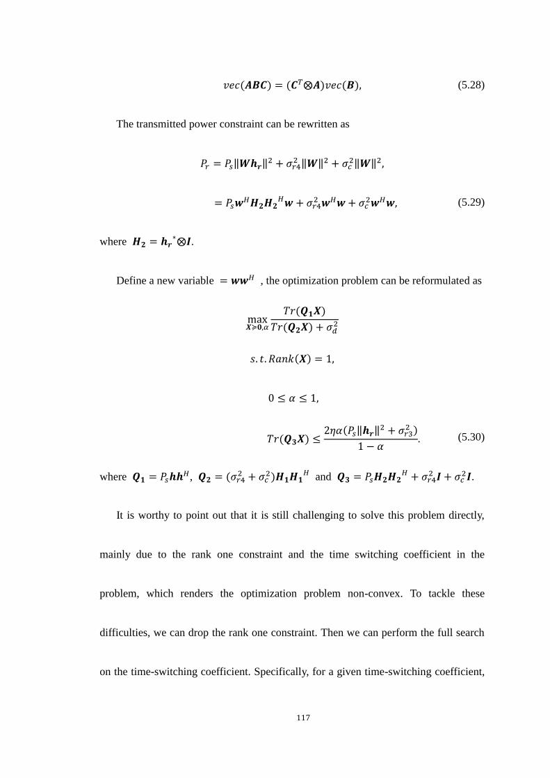
117
𝑣𝑒𝑐(𝑨𝑩𝑪) = (𝑪𝑇⨂𝑨)𝑣𝑒𝑐(𝑩), (5.28)
The transmitted power constraint can be rewritten as
𝑃𝑟 = 𝑃𝑠‖𝑾𝒉𝒓‖2 + 𝜎𝑟4
2 ‖𝑾‖2 + 𝜎𝑐2‖𝑾‖2,
= 𝑃𝑠𝒘𝐻𝑯𝟐𝑯𝟐
𝐻𝒘+ 𝜎𝑟42 𝒘𝐻𝒘+ 𝜎𝑐
2𝒘𝐻𝒘, (5.29)
where 𝑯𝟐 = 𝒉𝒓∗⨂𝑰.
Define a new variable = 𝒘𝒘𝐻 , the optimization problem can be reformulated as
max𝑿≽𝟎,𝛼
𝑇𝑟(𝑸𝟏𝑿)
𝑇𝑟(𝑸𝟐𝑿) + 𝜎𝑑2
𝑠. 𝑡. 𝑅𝑎𝑛𝑘(𝑿) = 1,
0 ≤ 𝛼 ≤ 1,
𝑇𝑟(𝑸𝟑𝑿) ≤2𝜂𝛼(𝑃𝑠‖𝒉𝒓‖
2 + 𝜎𝑟32 )
1 − 𝛼. (5.30)
where 𝑸𝟏 = 𝑃𝑠𝒉𝒉𝐻, 𝑸𝟐 = (𝜎𝑟4
2 + 𝜎𝑐2)𝑯𝟏𝑯𝟏
𝐻 and 𝑸𝟑 = 𝑃𝑠𝑯𝟐𝑯𝟐𝐻 + 𝜎𝑟4
2 𝑰 + 𝜎𝑐2𝑰.
It is worthy to point out that it is still challenging to solve this problem directly,
mainly due to the rank one constraint and the time switching coefficient in the
problem, which renders the optimization problem non-convex. To tackle these
difficulties, we can drop the rank one constraint. Then we can perform the full search
on the time-switching coefficient. Specifically, for a given time-switching coefficient,
118
the optimal relay beamforming matrix can be efficiently obtained. We perform a full
search on the time-switching coefficient, then solve the problem with all possible
value of the time-switching coefficient. In practice, we can discretize the range of the
time-switching coefficient into 𝑀 ≫ 1 equally spaced intervals with an interval
width of 1
𝑀 for facilitating the full search. After we obtain all achievable SNR value,
we can select the best among those possible choices of the time-switching coefficient.
Once the value of 𝛼 is fixed, the problem can be treated as a quasi-convex SDP
problem, where we drop the rank one constraint. Instead of employing the bisection
search approach, we use the Charnes-Cooper transformation [91] to solve it.
Specifically, we define a new variable 𝑡 =𝟏
𝑇𝑟(𝑸𝟐𝑿)+𝜎𝑑2 and let �̃� = 𝑡𝑿. The problem
can be recast as follows
max�̃�≽𝟎,𝑡
𝑇𝑟(𝑸𝟏�̃�)
𝑠. 𝑡. 𝑇𝑟(𝑸𝟐�̃�) + 𝑡𝜎𝑑2 = 1,
𝑇𝑟(𝑸𝟑�̃�) ≤2𝑡𝜂𝛼(𝑃𝑠‖𝒉𝒓‖
2 + 𝜎𝑟32 )
1 − 𝛼. (5.31)
Then the problem is solvable like the problem with the self-energy recycling relaying
protocol. The optimal solution is denoted by �̃�∗, 𝑡∗. Then the solution of 𝑿 denoted

119
by 𝑿∗ is obtained by 𝑿∗ =�̃�∗
𝑡∗. If the rank of �̃�∗ is not one, we can also use the SBP
rank reduction theorem to obtain the rank-one solution.
It is necessary to mention that we can also use the power splitting relaying
protocol as another benchmark scheme compared with the self-energy recycling
scheme. The power splitting relaying protocol can be referred as [60]. Our method to
optimize the beamforming with the time switching relaying protocol is easily
extended to the same optimization problem based on the power splitting relaying
protocol. Hence, we omit its detailed procedure here, and we provide its simulation
result in the next section.
5.5 Numerical Results
In this section, simulation results are provided to evaluate the performance of the
proposed beamforming optimization solution. The number of antenna is 3. We use the
TGn path loss model [101]. The loop channel path loss is −15 dB [102]. The distance
between each node is set as 10 m. The system bandwidth is 200 kHz. The carrier

120
frequency is 470 MHz, which is accorded with the IEEE 802.11af Wi-Fi parameters
[95]. The channel vectors are randomly generated from independent and identically
distributed Rayleigh Rician random variables with Rician factor 6dB. The noise
variance is assumed as 𝜎𝑟12 = 𝜎𝑟2
2 = 𝜎𝑟32 = 𝜎𝑟4
2 = 𝜎𝑐2 = 𝜎𝑑
2 = −25 dBm. The energy
conversion efficient is 0.8. Simulation results were averaged over 1000 independent
trials.
Figure 5.2: Achievable rate versus transmitted power at the source node for different
energy harvesting protocols.

121
In Fig. (5.2), the achievable rates achieved by different energy harvesting
protocols versus the transmitted power of the source are plotted. The result for the
self-energy recycling protocol is demonstrated and the results for the time switching
relaying protocol and the power splitting relaying protocol are also shown as
benchmarks. The results for time switching relaying and power splitting relaying
protocols are obtained with their optimal energy harvesting coefficient. It can be seen
that curves of the achievable rate for these energy harvesting protocols are
monotonically non-decreasing functions of the transmitted power because the higher
transmitted power results in more available power at the relay for the relay-destination
transmission. The self-energy recycling scheme outperforms the time switching
relaying and power splitting relaying protocols. This is because that the full-duplex
structure relay used in the self-energy recycling relaying protocol not only harvests
the power transmitted from the source node but also recycles the part of transmitted
power at the relay node. Compared to the time switching relaying and power splitting
relaying protocols, the self-energy harvesting protocol achieves an obvious rate gain.

122
The self-energy recycling protocol has better performance than the other energy
harvesting protocols.
Figure 5.3: Achievable rate versus transmitted power at the source node for the
self-energy recycling relaying protocol with different loop channel path loss.
In Fig. (5.3), the performances of the self-energy recycling protocol with different
loop channel path loss are presented. From the figure, we can see that the system
performance with the path loss −15 dB is better than that with the path loss −5 dB or
−25 dB. This is due to that if the path loss is smaller, the energy harvesting relay
123
cannot recycle more power in the second transmission phase, which leads to the
available transmitted power at the relay node is smaller. However, if the loop channel
path loss is too large, it will deteriorate the system performance, even though the relay
can harvest more power.
Figure 5.4: Performance comparison of the self-energy recycling protocol with
different numbers of antenna.

124
Figure 5.5: Performance comparison of the self-energy recycling protocol with
different numbers of distances.
In Fig. (5.4) and Fig. (5.5), we present the achievable rate versus the transmitted
power for the self-energy recycling relaying protocol with different system parameters.
It can be seen from the figure that the achievable rate improves with the increased
number of the antenna and is degraded with the increase of the distance between each
node. This is attributed to the fact that the relay could exploit the array gain to achieve
better performance with more antennas, and the longer distance makes channel

125
attenuation larger in turns resulting in, the worse performance of relay networks.
5.6 Chapter Summary
In this paper, we formulated the beamforming optimization problem in an AF relay
network based on the self-energy recycling relaying protocol. We proposed a
SDP-based solution to obtain the optimal solution for the proposed problem. To
demonstrate the advantage of the self-energy recycling relaying protocol, we also used
the SDP relaxation and the full search to solve the beamforming optimization problem
with the time switching relaying protocol and power splitting relaying protocol.
Simulation results illustrated that the self-energy recycling relaying protocol can
improve the achievable rate compared to other energy harvesting protocols. The
trade-off between the achievable rate and system parameters is also provided in the
chapter.

126
Chapter 6
Beamforming Optimization for Full-Duplex Cooperative
Cognitive Radio Networks with Self-Energy Recycling
Protocol
6.1 Introduction
The cooperation between the primary system and the secondary system in a cognitive
radio network was illustrated to improve the spectrum efficiency [103], [104], [105],
[106], [107], [108], [109]. When the PU’s rate requirement can not be met, the
secondary system assists in relaying the primary information for the PU and also uses
the primary spectrum. Hence the primary system and the secondary system both
benefit from the cooperation. In [106] and [107], a three phase transmission protocol
was proposed. Specifically, in phase 1 and phase 2, the ST receives the primary
information and then forwards to the PU. In phase 3, the ST sends its information to

127
the SU. In [103], [108] and [109], multiple antennas was employed at the ST, in which
the cooperation requires two phase. In phase 1, the ST listens to the primary
information. In phase 2, the ST both forwards the primary information and its
information. However, many works only considered the cooperation between the
primary system and the secondary system regarding the information level. From a
practical perspective, if the ST is willing to assist the primary transmission but faces a
problem that its energy can not support the information cooperation, the information
cooperation will not be completed. To solve this problem, we introduce the emerging
wireless energy harvesting technology into the cooperative cognitive radio network.
In this chapter, we study the beamforming optimization problem based on the
self-energy recycling relaying protocol in a cooperative cognitive radio network. We
modeled a wireless energy harvesting cooperative cognitive radio network with a
self-energy recycling relay. The ST is equipped two groups of the antenna, so it is
capable of collecting the information or energy and relaying the information
simultaneously. In this model, we formulated the beamforming optimization problem
for maximizing the achievable SU’s rate subject to the available transmitted power at

128
the ST and the minimum PU’s rate. We used the SDP relaxation approach to solving it.
To highlight the advantage of the self-energy recycling scheme, we also provided the
solution for the beamforming optimization problem with the power splitting relaying
protocol. Simulation results are provided to verify that the self-energy recycling
relaying protocol achieves an obvious rate gain compared to the power splitting
relaying protocol. The trade-off between the achievable rate and system parameters is
also analyzed.
6.2 System Model
The cognitive relay network considered in the chapter includes a primary system and a
secondary system. The secondary system consists of a secondary transmitter-receiver
pair. The primary system has a primary transmitter-receiver pair, which intends to
communicate in a licensed frequency band. We assume that the link between the PT
and PU is affected with the deep fading or shadowing effects, hence to meet the
primary system’s rate requirement, the ST assists in relaying the primary system’s
129
information. The ST is an energy harvesting node [60], which has an initial energy and
further harvests energy from the PT. The ST receives the PT’s information and energy;
it uses the harvested energy together with its energy to transmit the information to the
SU and to assist the primary system. The battery capacity of the ST is assumed as
infinite. The AF scheme is employed at the ST node. A self-energy recycling protocol
is employed at the energy harvesting node. The detailed analysis based on this
protocol is given in the following section.
Except the ST, all nodes are equipped one antenna. The ST has two groups of RF
chains; one is used for transmitting while the other one is used for receiving. The
number of transmission antennas 𝑁𝑡 and the number of receiving antennas 𝑁𝑟 are
same, i.e. 𝑁𝑡 = 𝑁𝑟 = 𝑁. The perfect channel state information is assumed available at
the ST. Channels are modeled as quasi-static block fading channels. The considered
model is illustrated in Fig. (6.1).
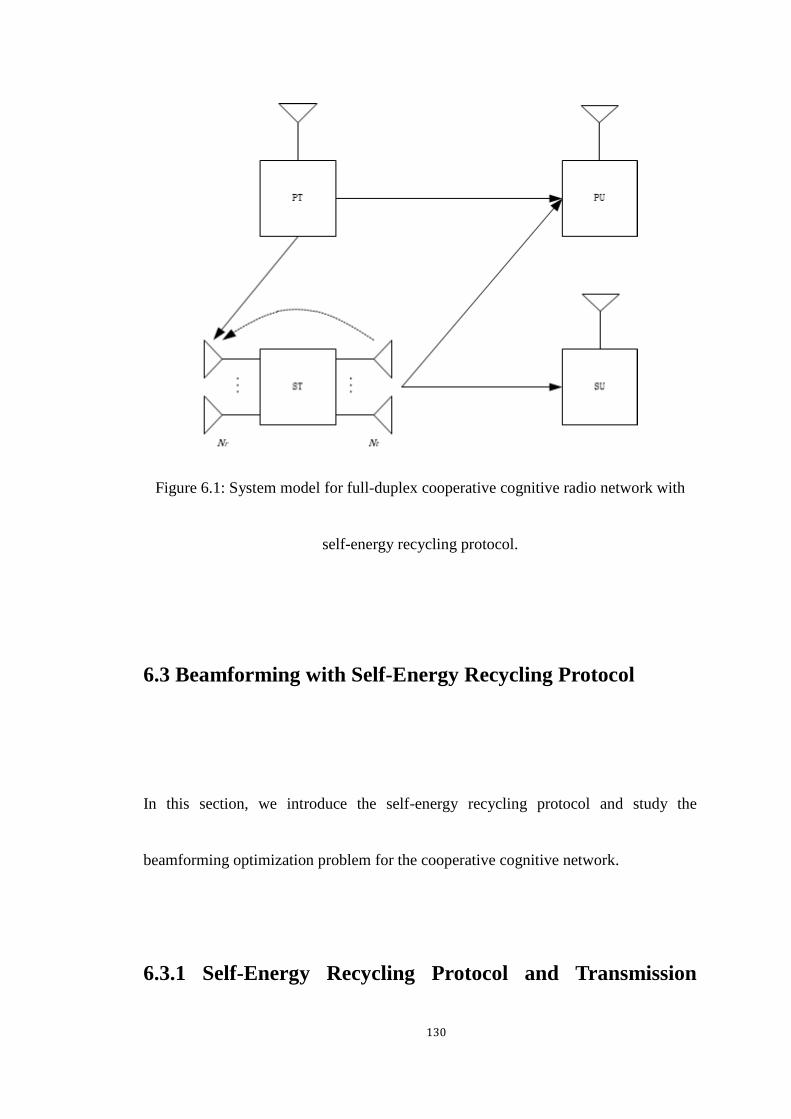
130
Figure 6.1: System model for full-duplex cooperative cognitive radio network with
self-energy recycling protocol.
6.3 Beamforming with Self-Energy Recycling Protocol
In this section, we introduce the self-energy recycling protocol and study the
beamforming optimization problem for the cooperative cognitive network.
6.3.1 Self-Energy Recycling Protocol and Transmission
131
Model
The PT broadcasts the information firstly. The ST receives the information from the
PT with its receiving antenna. The received information can be expressed as
𝒚𝒓𝟏 = √𝑃𝑝𝒉𝑥𝑝 + 𝒏𝒓𝟏, (6.1)
where 𝑃𝑝 is the transmitted power at the PT, 𝒉 ∈ ℂ𝑁×1 is the channel vector from
the PT to receiving antennas of the ST, and 𝑥𝑝 is the transmitted information from
the PT with ℰ (|𝑥𝑝|2) = 1 and 𝒏𝒓𝟏 is the additive complex Gaussian noise vector at
the ST following 𝒞𝒩(𝟎, 𝜎𝑟12 𝑰𝑁). In the same time, the received information at the PU
can be expressed as
𝑦𝑝1 = √𝑃𝑝ℎ𝑝𝑥𝑝 + 𝑛𝑝1, (6.2)
where ℎ𝑝 is the channel between the PT and PU, 𝑛𝑝1 is the additive complex
Gaussian noise vector at the PU following 𝒞𝒩(0, 𝜎𝑝12 ).
After the ST receives the information from the PT, it amplifies the received
information with the precoding. The ST superimposes the amplified information for
the PU and its information with the cognitive beamforming vector for the SU. The

132
superimposable information can be expressed as
𝒙𝒓 = √𝑃𝑝𝑾𝒉𝑥𝑝 +𝑾𝒏𝒓𝟏 +𝒘𝒔𝑥𝑠, (6.3)
where 𝑾 ∈ ℂ𝑁×𝑁 is the precoding matrix, 𝒘𝒔 ∈ ℂ𝑁×1 is the cognitive beamforming
vector and 𝑥𝑠 is the information for the PU with ℰ(|𝑥𝑠|2) = 1.
The power of the transmitted signal at the ST is
𝑃𝑟 = 𝑃𝑝‖𝑾𝒉‖2 + 𝜎𝑟12 ‖𝑾‖2 + ‖𝒘𝒔‖
2, (6.4)
In the second phase, the ST uses its transmission antennas to relay the information
for the PU and SU. The received signal at the PU is given by
𝑦𝑝2 = √𝑃𝑝𝒈𝒑
𝐻𝑾𝒉𝑥𝑝 + 𝒈𝒑𝐻𝑾𝒏𝒓𝟏 +𝒈𝒑
𝐻𝒘𝒔𝑥𝑠 + 𝑛𝑝2, (6.5)
where 𝒈𝒑 ∈ ℂ𝑁×1 is the channel vector between transmission antennas of the ST and
the PU and 𝑛𝑝2 is additive Gaussian noise at the destination following 𝒞𝒩(0, 𝜎𝑝22 ).
The received signal at the SU is given by
𝑦𝑠 = √𝑃𝑝𝒈𝒔𝐻𝑾𝒉𝑥𝑝 + 𝒈𝒔
𝐻𝑾𝒏𝒓𝟏 + 𝒈𝒔𝐻𝒘𝒔𝑥𝑠 + 𝑛𝑠, (6.6)
where 𝒈𝒔 ∈ ℂ𝑁×1 is the channel vector between transmission antennas of the ST and
the PU and 𝑛𝑠 is additive Gaussian noise at the destination following 𝒞𝒩(𝟎, 𝜎𝑠2).
Concurrently, the ST is wirelessly powered by the PT with the dedicated energy-
133
bearing signal. The received signal at the ST is
𝒚𝒓𝟐 = √𝑃𝑝𝒉𝑥𝑒 +𝑯𝒓𝑥𝑟 + 𝒏𝒓𝟐,
= √𝑃𝑝𝒉𝑥𝑒 +√𝑃𝑝𝑯𝒓𝑾𝒉𝑥𝑝 +𝑯𝒓𝑾𝒏𝒓𝟏 +𝑯𝒓𝒘𝒔𝑥𝑠 + 𝒏𝒓𝟐, (6.7)
where 𝑥𝑒 is the transmitted signal from the PT with ℰ(|𝑥𝑒|2) = 1, 𝑯𝒓 ∈ ℂ𝑁×𝑁 is
the channel matrix of the loop channel at the ST and 𝒏𝒓𝟐 is the received additive
complex Gaussian noise vector following 𝒞𝒩(𝟎, 𝜎𝑟22 𝑰𝑁). The ST not only harvests
energy from the PT but also recycles part of its transmitted power due to its two
groups of the antenna being activated at the same time. Unlike the other full-duplex
structure studies, the full-duplex node uses interference cancellation techniques to
eliminate the loop-back interference signal. In energy harvesting networks, the
loop-back signal can be reused at the energy harvesting node as a part of transmitted
power. The amount of the harvested energy at the ST is given by
𝐸 =𝜂𝑇
2(𝑃𝑝‖𝒉‖
2 + 𝑃𝑝‖𝑯𝒓𝑾𝒉‖2 + 𝜎𝑟12 ‖𝑯𝒓𝑾‖2 + ‖𝑯𝒓𝒘𝒔‖
2
+ 𝜎𝑟22 ), (6.8)
where 𝜂 is the energy conversion efficiency coefficient at the ST. Then the total
available transmitted power at the ST is 𝐸
𝑇 2⁄, which can be expressed as

134
𝑃𝑟𝑚𝑎𝑥 = 𝜂(𝑃𝑝‖𝒉‖
2 + 𝑃𝑝‖𝑯𝒓𝑾𝒉‖2 + 𝜎𝑟12 ‖𝑯𝒓𝑾‖2 + ‖𝑯𝒓𝒘𝒔‖
2
+ 𝜎𝑟22 ) + 𝐸𝑟
𝑖𝑛𝑖 , (6.9)
where 𝐸𝑟𝑖𝑛𝑖 is the initial energy at the ST.
According to the signal as mentioned earlier model and applying the MRC
strategy to 𝑦𝑝1 and 𝑦𝑝
2. The received SINR at the PU is the sum of two channel uses,
it is
𝑆𝐼𝑁𝑅𝑝 =𝑃𝑝|ℎ𝑝|
2
𝜎𝑝12 +
𝑃𝑝|𝒈𝒑𝐻𝑾𝒉|
2
𝜎𝑟12 ‖𝒈𝒑
𝐻𝑾‖2+ |𝒈𝒑
𝐻𝒘𝒔|2+ 𝜎𝑝2
, (6.10)
The achievable rate of the PU can be presented as
𝑅𝑝 =1
2log2(1 + 𝑆𝐼𝑁𝑅𝑝), (6.11)
The received SINR at the SU is
𝑆𝐼𝑁𝑅𝑠 =|𝒈𝒔
𝐻𝒘𝒔|2
𝑃𝑝|𝒈𝒔𝐻𝑾𝒉|2 + 𝜎𝑟1
2 ‖𝒈𝒔𝐻𝑾‖2 + 𝜎𝑠2
, (6.12)
The achievable rate of the SU can be presented as
𝑅𝑠 =1
2log2(1 + 𝑆𝐼𝑁𝑅𝑠), (6.13)
6.3.2 Problem Formulation and Beamforming Design

135
In this section, we discuss the beamforming optimization in the considered cognitive
network. Our objective is to maximize the SU’s rate subject to the PU rate and
transmitted power constraint by jointly optimizing the precoding and the cognitive
beamforming. Particularly the addressed optimization problem is formulated as
follows
max𝑾,𝒘𝒔
𝑅𝑠
𝑠. 𝑡. 𝑅𝑝 ≥ 𝑟𝑝,
𝑃𝑟 ≤ 𝑃𝑟𝑚𝑎𝑥. (6.14)
where 𝑟𝑝 is the minimum rate requirement for the PU.It is obvious that the problem
stated above is not a standard convex problem. Then, we proposed an optimal solution
based on SDP relaxation. By using the monotonicity, the original problem can be
expressed as
max𝑾,𝒘𝒔
|𝒈𝒔𝐻𝒘𝒔|
2
𝑃𝑝|𝒈𝒔𝐻𝑾𝒉|2 + 𝜎𝑟1
2 ‖𝒈𝒔𝐻𝑾‖2 + 𝜎𝑠2
𝑠. 𝑡.𝑃𝑝|ℎ𝑝|
2
𝜎𝑝12 +
𝑃𝑝|𝒈𝒑𝐻𝑾𝒉|
2
𝜎𝑟12 ‖𝒈𝒑
𝐻𝑾‖2+ |𝒈𝒑
𝐻𝒘𝒔|2+ 𝜎𝑝2
≥ 𝑟𝑝,
136
𝑃𝑝‖𝑾𝒉‖2 + 𝜎𝑟12 ‖𝑾‖2 + ‖𝒘𝒔‖
2
≤ 𝜂(𝑃𝑝‖𝒉‖2 + 𝑃𝑝‖𝑯𝒓𝑾𝒉‖2 + 𝜎𝑟1
2 ‖𝑯𝒓𝑾‖2
+ ‖𝑯𝒓𝒘𝒔‖2 + 𝜎𝑟2
2 ) + 𝑃𝑟𝑖𝑛𝑖 .
(6.15)
In the above problem, the precoding matrix 𝑾 can be characterized as 𝑾 =
𝒘𝒑𝒉𝐻. It can be proved this structure is the optimal structure of 𝑾 [103]. This
structure amplifies the received signal from the PT employing 𝒉𝐻 to produce a noisy
version of the primary information and forward the information with the beamforming
𝒘𝒑. It also simplifies the above problem. Therefore, the problem can be further
expressed as
max𝒘𝒑,𝒘𝒔
|𝒈𝒔𝐻𝒘𝒔|
2
(𝑃𝑝‖𝒉‖4 + 𝜎𝑟12 ‖𝒉‖2)|𝒈𝒔𝐻𝒘𝒑|
2+ 𝜎𝑠2
𝑠. 𝑡. (𝑃𝑝‖𝒉‖4 − 𝑟𝑝𝜎𝑟1
2 ‖𝒉‖2)|𝒈𝒑𝐻𝒘𝒑|
2− 𝑟𝑝|𝒈𝒑
𝐻𝒘𝒔|2≥ 𝑟�̅�𝜎𝑝
2,
(𝑃𝑝‖𝒉‖4 + 𝜎𝑟1
2 ‖𝒉‖2) (‖𝒘𝒑‖2− 𝜂‖𝑯𝒓𝒘𝒑‖
2) + ‖𝒘𝒔‖
2
− 𝜂‖𝑯𝒓𝒘𝒔‖2 ≤ 𝜂𝑃𝑝‖𝒉‖
2 + 𝜂𝜎𝑟22 + 𝑃𝑟
𝑖𝑛𝑖 . (6.16)
where 𝑟�̅� = 𝑟𝑝 −𝑃𝑝|ℎ𝑝|
2
𝜎𝑝12 . Define a new variable 𝑿 = 𝒘𝒑𝒘𝒑
𝐻 and 𝒀 = 𝒘𝒔𝒘𝒔𝐻, the
optimization problem can be reformulated as
max𝑿≽𝟎,𝒀≽𝟎
𝑇𝑟(𝑸𝟏𝑿)
𝑇𝑟(𝑸𝟐𝑿) + 𝜎𝑠2
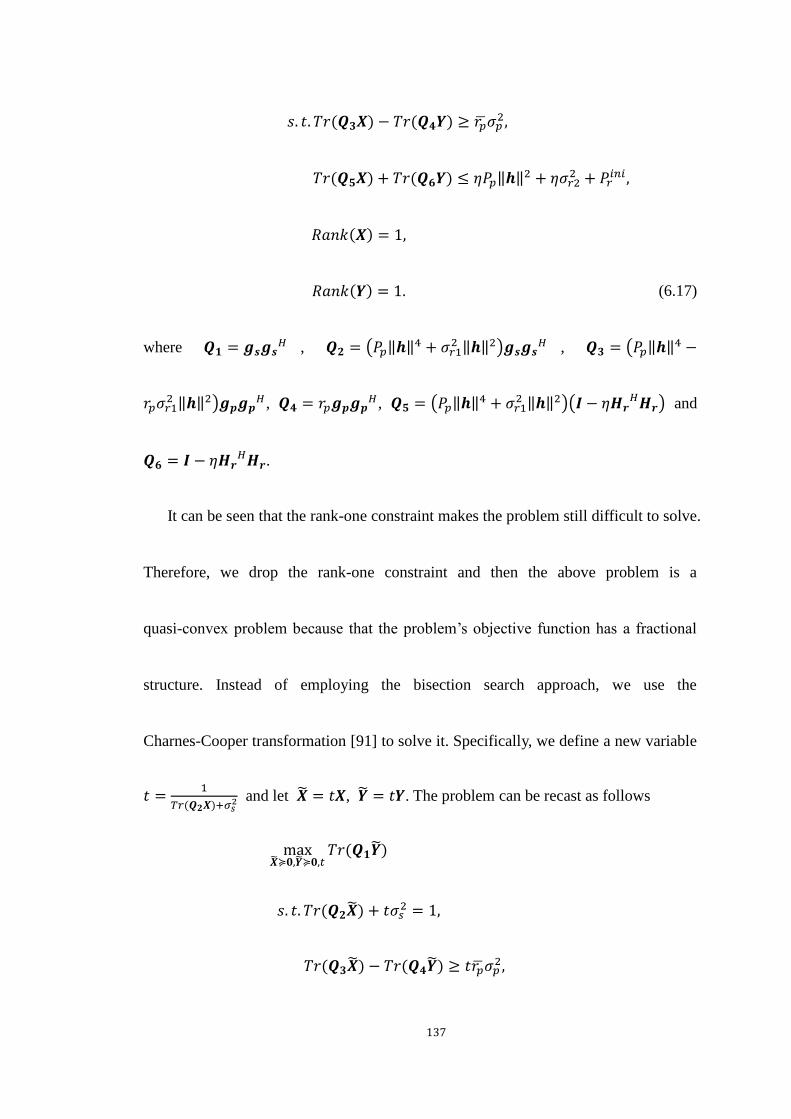
137
𝑠. 𝑡. 𝑇𝑟(𝑸𝟑𝑿) − 𝑇𝑟(𝑸𝟒𝒀) ≥ 𝑟�̅�𝜎𝑝2,
𝑇𝑟(𝑸𝟓𝑿) + 𝑇𝑟(𝑸𝟔𝒀) ≤ 𝜂𝑃𝑝‖𝒉‖2 + 𝜂𝜎𝑟2
2 + 𝑃𝑟𝑖𝑛𝑖 ,
𝑅𝑎𝑛𝑘(𝑿) = 1,
𝑅𝑎𝑛𝑘(𝒀) = 1.
(6.17)
where 𝑸𝟏 = 𝒈𝒔𝒈𝒔𝐻 , 𝑸𝟐 = (𝑃𝑝‖𝒉‖
4 + 𝜎𝑟12 ‖𝒉‖2)𝒈𝒔𝒈𝒔
𝐻 , 𝑸𝟑 = (𝑃𝑝‖𝒉‖4 −
𝑟𝑝𝜎𝑟12 ‖𝒉‖2)𝒈𝒑𝒈𝒑
𝐻 , 𝑸𝟒 = 𝑟𝑝𝒈𝒑𝒈𝒑𝐻 , 𝑸𝟓 = (𝑃𝑝‖𝒉‖
4 + 𝜎𝑟12 ‖𝒉‖2)(𝑰 − 𝜂𝑯𝒓
𝐻𝑯𝒓) and
𝑸𝟔 = 𝑰 − 𝜂𝑯𝒓𝐻𝑯𝒓.
It can be seen that the rank-one constraint makes the problem still difficult to solve.
Therefore, we drop the rank-one constraint and then the above problem is a
quasi-convex problem because that the problem’s objective function has a fractional
structure. Instead of employing the bisection search approach, we use the
Charnes-Cooper transformation [91] to solve it. Specifically, we define a new variable
𝑡 =1
𝑇𝑟(𝑸𝟐𝑿)+𝜎𝑠2 and let �̃� = 𝑡𝑿, �̃� = 𝑡𝒀. The problem can be recast as follows
max�̃�≽𝟎,�̃�≽𝟎,𝑡
𝑇𝑟(𝑸𝟏�̃�)
𝑠. 𝑡. 𝑇𝑟(𝑸𝟐�̃�) + 𝑡𝜎𝑠2 = 1,
𝑇𝑟(𝑸𝟑�̃�) − 𝑇𝑟(𝑸𝟒�̃�) ≥ 𝑡𝑟�̅�𝜎𝑝2,
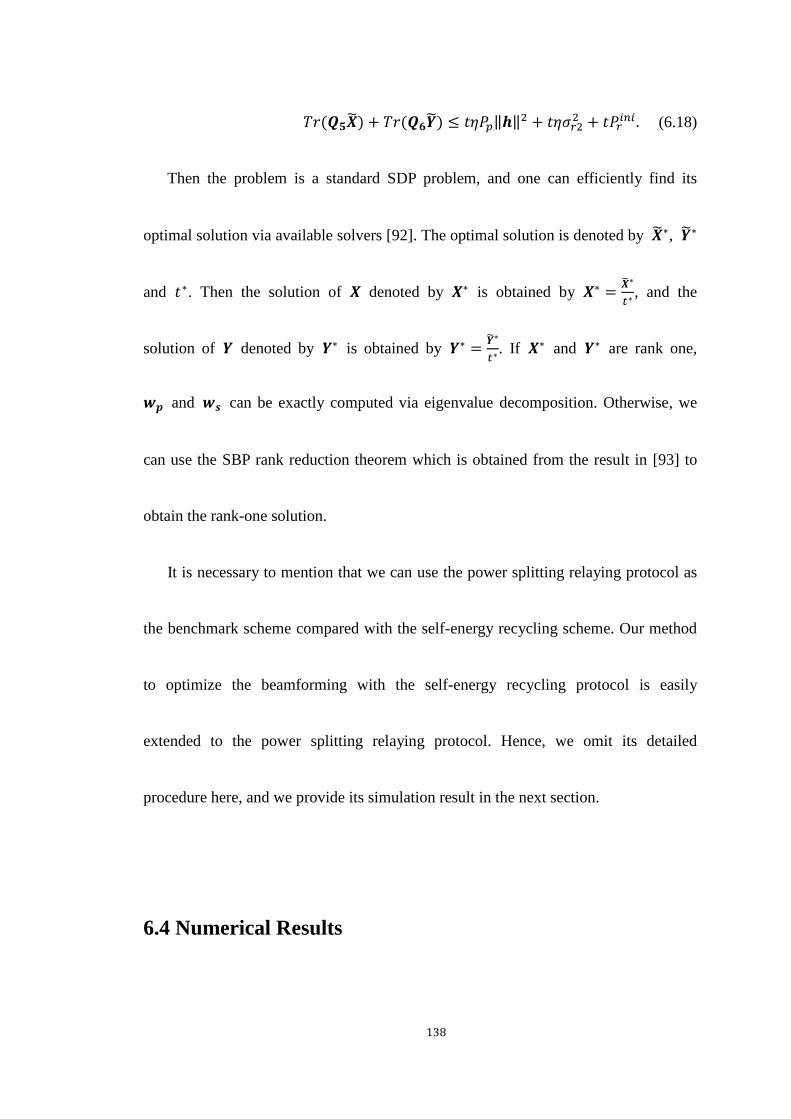
138
𝑇𝑟(𝑸𝟓�̃�) + 𝑇𝑟(𝑸𝟔�̃�) ≤ 𝑡𝜂𝑃𝑝‖𝒉‖2 + 𝑡𝜂𝜎𝑟2
2 + 𝑡𝑃𝑟𝑖𝑛𝑖 . (6.18)
Then the problem is a standard SDP problem, and one can efficiently find its
optimal solution via available solvers [92]. The optimal solution is denoted by �̃�∗, �̃�∗
and 𝑡∗. Then the solution of 𝑿 denoted by 𝑿∗ is obtained by 𝑿∗ =�̃�∗
𝑡∗, and the
solution of 𝒀 denoted by 𝒀∗ is obtained by 𝒀∗ =�̃�∗
𝑡∗. If 𝑿∗ and 𝒀∗ are rank one,
𝒘𝒑 and 𝒘𝒔 can be exactly computed via eigenvalue decomposition. Otherwise, we
can use the SBP rank reduction theorem which is obtained from the result in [93] to
obtain the rank-one solution.
It is necessary to mention that we can use the power splitting relaying protocol as
the benchmark scheme compared with the self-energy recycling scheme. Our method
to optimize the beamforming with the self-energy recycling protocol is easily
extended to the power splitting relaying protocol. Hence, we omit its detailed
procedure here, and we provide its simulation result in the next section.
6.4 Numerical Results

139
In this section, simulation results are provided to evaluate the performance of the
proposed beamforming optimization solution. The number of antenna is 3. We use the
TGn path loss model [101]. The loop channel path loss is −15 dB [102]. The channel
vectors are randomly generated from independent and identically distributed Rayleigh
Rician random variables with Rician factor 6dB. The initial power at the ST is 10
dBm. The minimum requirement rate of the PU is 3 bps/Hz. The distance between
each node is set as 10 m. The system bandwidth is 200 kHz. The carrier frequency is
470 MHz, which is accorded with the IEEE 802.11af Wi-Fi parameters [95]. The
noise variance is assumed as 𝜎𝑟12 = 𝜎𝑟2
2 = 𝜎𝑝12 = 𝜎𝑝2
2 = 𝜎𝑠2 = −25 dBm. The energy
conversion efficient is 0.8. Simulation results were averaged over 1000 independent
trials.
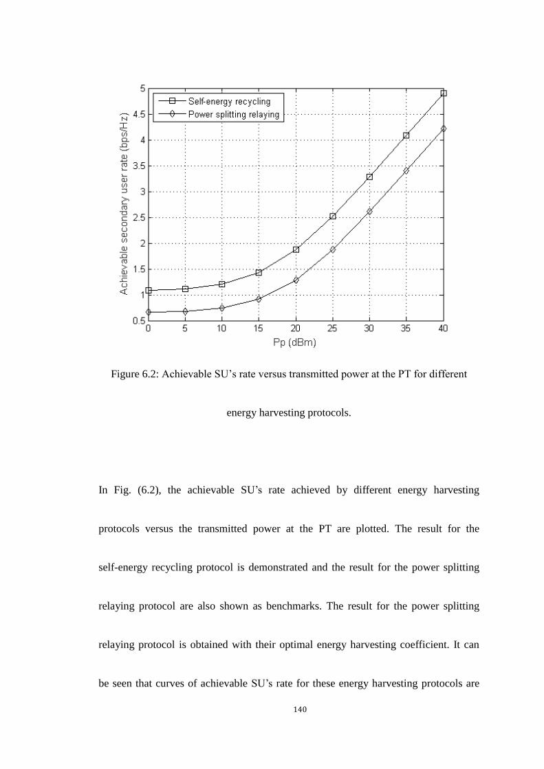
140
Figure 6.2: Achievable SU’s rate versus transmitted power at the PT for different
energy harvesting protocols.
In Fig. (6.2), the achievable SU’s rate achieved by different energy harvesting
protocols versus the transmitted power at the PT are plotted. The result for the
self-energy recycling protocol is demonstrated and the result for the power splitting
relaying protocol are also shown as benchmarks. The result for the power splitting
relaying protocol is obtained with their optimal energy harvesting coefficient. It can
be seen that curves of achievable SU’s rate for these energy harvesting protocols are

141
monotonically non-decreasing functions of the transmitted power at the PT because
the higher transmitted power results in more available power at the ST for the
broadcasting transmission. The self-energy recycling protocol outperforms the power
splitting relaying protocol. This is because that the full-duplex structure used in the
self-energy recycling relaying protocol not only harvests the power transmitted from
the PT but also recycles the part of transmitted power at the ST. Compared to the
power splitting relaying protocol, the self-energy harvesting protocol achieves an
obvious rate gain. The self-energy recycling protocol has better performance than the
other energy harvesting protocol.
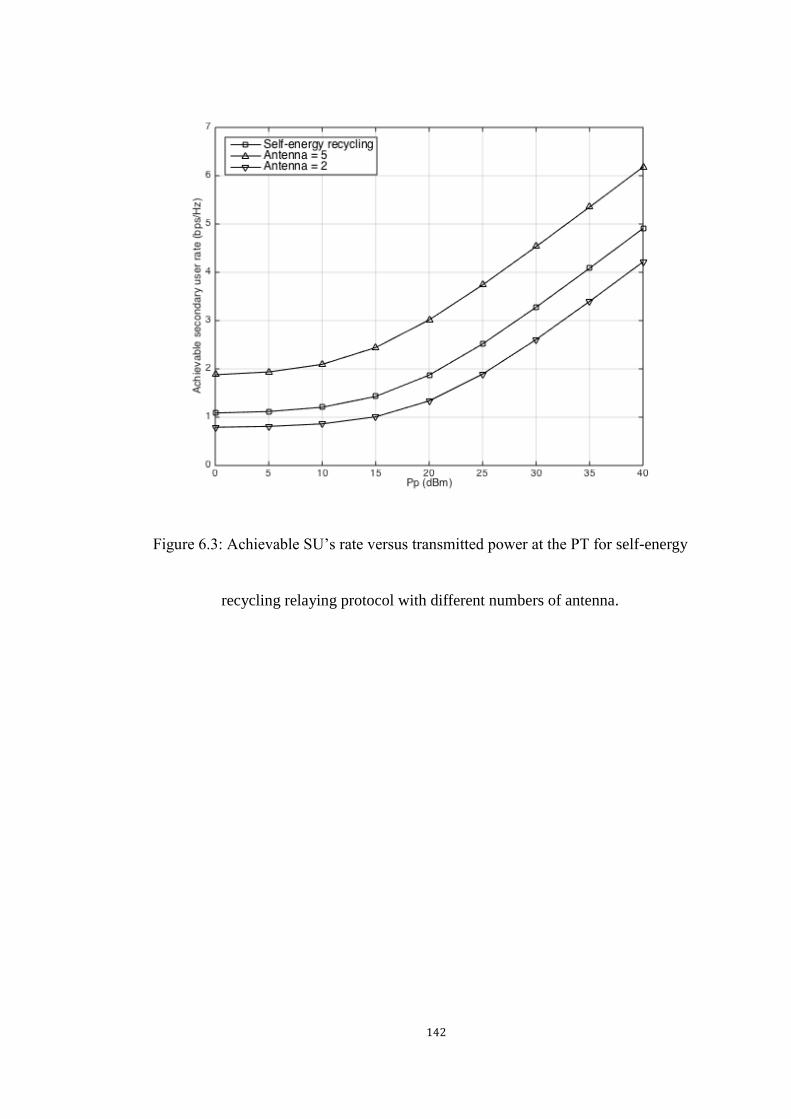
142
Figure 6.3: Achievable SU’s rate versus transmitted power at the PT for self-energy
recycling relaying protocol with different numbers of antenna.

143
Figure 6.4: Achievable SU’s rate versus transmitted power at the PT for self-energy
recycling relaying protocol with different distances.
In Fig. (6.3) and Fig. (6.4), we present the achievable SU’s rate versus the
transmitted power at the PT for the self-energy recycling relaying protocol with
different system parameters. It can be seen from the figure that the achievable SU’s
rate improves with the increased number of the antenna and is degraded with the
increase of the distance between each node. This is attributed to the fact that the ST
could exploit the array gain to achieve better performance with more antennas, and the

144
longer distance makes channel attenuation larger in turns resulting in, the worse
performance.
6.5 Chapter Summary
In this chapter, we formulated the beamforming optimization problem in a cooperative
cognitive radio network based on the self-energy recycling relaying protocol. We
proposed a SDP-based solution to obtain the optimal solution for the proposed
problem. To demonstrate the advantage of the self-energy recycling relaying protocol,
we also used the SDP relaxation and 1-D optimization to solve the beamforming
optimization problem the power splitting relaying protocol. Simulation results
illustrated that the self-energy recycling relaying protocol could improve the
achievable SU’s rate compared to the power splitting relaying protocol. The trade-off
between the achievable SU’s rate and system parameters is also provided.

145
Chapter 7
Conclusion and Future Works
7.1 Conclusion
In this thesis, the wireless energy harvesting technique and some optimization studies
regarding applications of the wireless energy harvesting in different communication
networks are investigated. For optimization problems proposed in the thesis, we
develop mathematical algorithms to find optimal solutions, and simulation results are
provided to verify the effectiveness of solutions.
In the first Chapter, an overview of wireless energy harvesting is introduced. In the
past, the initial idea of wireless energy harvesting was not practical to implement due
to the low energy efficiency. Recently, the development of circuit technology and an
increasing number of the low-powered electronic device make the wireless energy
harvesting attracts more and more attention from both academic and industry fields.

146
In Chapter 2, the background of wireless energy harvesting is presented. The
architecture of wireless energy harvesting network, the introduction of the different
power source and practical applications of wireless energy harvesting are discussed.
Also, an important energy harvesting technique used in communication networks is
introduced, which refers as SWIPT. SWIPT is that the network node uses the same
antenna module to perform receiving information and harvesting energy. Nevertheless,
due that the existing circuit has some practical issues to simultaneously processing the
information reception and energy harvesting, some structures of the communication
network node are proposed to achieve the practical implementation of SWIPT.
Chapter 3 focused on an energy-efficient optimization in the cooperative network
with wireless information and power transfer. The energy harvesting technique is used
at the relay node in a DF cooperative network. Based on the time switching relaying
protocol and power splitting relaying protocol, optimization problems of energy
efficiency are formulated. The formulated problems can be re-constructed into a
convex form by using the nonlinear fractional programming, to which closed form
solutions can be found by using the Lagrange multiplier method. Simulation results

147
are presented in this chapter to verify the effectiveness of this solution.
In chapter 4, the secure communication in the cooperative network with wireless
information and power transfer is discussed. The secure communication issue is
considered in an AF cooperative network with an energy harvesting relay node. Based
on the time switching relaying protocol and power splitting relaying protocol, the
problem for maximizing the secrecy rate subject to the transmitted power and energy
harvesting coefficient is proposed. To find the optimal solution, SDP relaxation, and
1-D optimization are used. Simulation results are presented to show the system
performance for two energy harvesting protocols.
A self-energy recycling protocol is proposed in chapter 5. Based on this energy
harvesting protocol, we study the beamforming optimization problem in an energy
harvesting cooperative full-duplex network. The problem is to maximize the
achievable rate subject to the available transmitted power at the relay node. The SDP
method is used to solve the problem. For comparison, we also propose a beamforming
optimization problem based on the time switching relaying protocol. The self-energy
recycling protocol can achieve a significant rate gain compared to the other energy

148
harvesting protocol.
In chapter 6, we use the self-energy recycling protocol in a full-duplex cooperative
cognitive radio network. In considered network, the channel of the primary system is
affected with deep fading or shadowing effects, the ST harvests energy from the PT
and assists the primary information transmission. The ST has a full-duplex structure
and employs the self-energy recycling protocol. The problem aims to maximize the
achievable SU’s rate subject to the available transmitted power at the ST and
minimum rate requirement for the PU. The system performance with the self-energy
recycling protocol is compared to it with the other energy harvesting protocol in the
simulation.
7.2 Future Works
It is recommended that further research be undertaken in the following areas:
For the energy efficiency study in the wireless energy harvesting network, it is
potential to extend the work in the thesis into the more complex communication

149
network with SWIPT, such as multi-user relaying network with AF or DF relaying
protocol. And it is excited to study the energy efficiency algorithm with the convex
optimization in the multi-antenna network with energy harvesting, such as MIMO or
MISO.
For the secure communication with SWIPT, it is possible to extend the SDP
method into the MIMO network. And it is also interesting to study the more complex
security issue with energy harvesting, such as the network with jammers or the
untrusted relay node. The convex technique for the secure issue can also be
investigated more in the future.
In the full-duplex network model, there will be more interesting problem. The
full-duplex structure provides the self-recycling energy harvesting protocol compared
to the half-duplex model, which brings more different resource allocation convex
problems that could be optimized in many communication networks.

150
Appendix
In the appendix, the convergence of proposed algorithm in Chapter 3 regarding
transformed parametric problems is proved. First of all, we introduce two lemmas.
Lemma 1. The object function 𝐶 − 𝑞∗𝐸𝑐 is a monotonic decreasing function of 𝑞∗.
Proof. Given two power allocation results in 𝑃𝑠𝑎 and 𝑃𝑠𝑏 with their corresponding
energy efficiency 𝑞𝑎∗ and 𝑞𝑏
∗ . We define 𝑞𝑎∗ > 𝑞𝑏
∗ , then we have
max𝑃𝑠
𝐶 − 𝑞𝑏∗𝐸𝑐
= 𝐶(𝑃𝑠𝑏) − 𝑞𝑏∗𝐸𝑐(𝑃𝑠𝑏)
> 𝐶(𝑃𝑠𝑎) − 𝑞𝑏∗𝐸𝑐(𝑃𝑠𝑎)
≥ 𝐶(𝑃𝑠𝑎) − 𝑞𝑎∗𝐸𝑐(𝑃𝑠𝑎)
= max𝑃𝑠
𝐶 − 𝑞𝑎∗𝐸𝑐, ∎
Lemma 2. There is an energy efficiency solution 𝑞∗ to ensure 𝐶 − 𝑞∗𝐸𝑐 = 0.
Proof. It can be proved that the objective function is continuous in 𝑞∗. If 𝑞∗ is plus
infinity, the value of the objective function is minus infinity and vice-versa. Hence,

151
there is a 𝑞∗ to let 𝐶 − 𝑞∗𝐸𝑐 = 0. ∎
With the above lemmas, we can prove the convergence of the transformed
parametric problem. We denote 𝑃𝑠𝑛 and 𝑞𝑛∗ as the energy efficiency policy in the
n-th iteration. Recall that in the algorithm, 𝑞𝑛+1∗ =
𝐶(𝑃𝑠𝑛)
𝐸𝑐(𝑃𝑠𝑛)
. Then we have
𝐶(𝑃𝑠𝑛) − 𝑞𝑛∗𝐸𝑐(𝑃𝑠𝑛)
= 𝑞𝑛+1∗ 𝐸𝑐(𝑃𝑠𝑛) − 𝑞𝑛
∗𝐸𝑐(𝑃𝑠𝑛)
= (𝑞𝑛+1∗ − 𝑞𝑛
∗)𝐸𝑐(𝑃𝑠𝑛),
where 𝐸𝑐(𝑃𝑠𝑛) is greater than 0, therefore, 𝑞𝑛+1∗ − 𝑞𝑛
∗ ≥ 0 , The 𝑞𝑛∗ is
non-decreasing in the iterative process. In Lemma 1, the objective function is
monotonically decreasing in 𝑞𝑛∗ and 𝑞𝑛
∗ is non-decreasing in the iteration. Therefore,
the objective function is non-increasing in the iteration. In Lemma 2, the optimum
energy efficiency converges when 𝐶 − 𝑞∗𝐸𝑐 = 0 . If the iteration index is large
enough, 𝐶 − 𝑞∗𝐸𝑐 will equal to 0. Moreover, the optimal energy efficiency will be
obtained.

152
References
[1] H. J. Visser and R. J. Vullers, “RF energy harvesting and transport for wireless
sensor network applications: Principles and requirements,” in Proceedings of
the IEEE, June 2013, pp. 1410-1423.
[2] A. Sample and J. R. Smith, “Experimental results with two wireless power
transfer systems,” in Proc. IEEE Radio and Wireless Symposium (RWS), San
Diego, USA, Jan. 2009.
[3] H. Nishimoto, Y. Kawahara, and T. Asami, “Prototype implementation of
ambient RF energy harvesting wireless sonsor networks,” in Proceedings of
IEEE Sensors, Kona, Hawaii, USA, November 2010.
[4] X. Zhang, H. Jiang, L. Zhang, C. Zhang, Z. Wang, and X. Chen, “An
energy-efficient ASIC for wireless body sensor networks in medical
applications,” IEEE Transactions on Biomedical Circuits and Systems, vol. 4,
no. 1, pp. 11-18, February 2010.
[5] N. Shinohara, “Development of rectenna with wireless communication system,”

153
in Proc. European Conf. Ant. Prop., Rome, Italy, April 2011, pp. 3970-3973.
[6] R. Zhang and C. K. Ho, “MIMO broadcasting for simultaneous wireless
information and power transfer,” IEEE Trans. Wireless Commun., vol. 12, no.
5, pp. 1989-2001, May 2013.
[7] W. C. Brown, “Experiments involving a microwave beam to power and
position a helicopter,” IEEE Trans. Aerosp. Electron. Syst., vol. AES-5, no. 5,
pp. 692-702, Sep. 1969.
[8] J. O. Mcspadden and J. C. Mankins, “Space solar power programs and
microwave wireless power transmission technology,” IEEE Microw. Mag., vol.
3, no. 4, pp. 46-57, Apr. 2002.
[9] K. Huang and V. K. N. Lau, “Enabling wireless power transfer in cellular
networks: Architecture, modeling and deployment,” IEEE Trans. Wireless
Commun, vol. 13, no. 2, pp. 902-912, Feb. 2014.
[10] L. Liu, R. Zhang, and K. C. Chua, “Multi-antenna wireless powered
communication with energy beamforming,” IEEE Trans. Commun., vol. 62, no.
12, pp. 4349-4361, Dec. 2014.

154
[11] X. Chen, X. Wang, and X. Chen, “Energy-efficient optimization for wireless
information and power transfer in large-scale MIMO systems employing
energy beamforming,” IEEE Wireless Commun. Lett., vol. 2, no. 6, pp.
667-670, Dec. 2013.
[12] Z. Popovic, “Cut the cord: Low-power far-field wireless powering,” IEEE
Microw. Mag., vol. 14, no. 2, pp. 55-62, 2013.
[13] Powercast. [Online]. Available: www.powercastco.com
[14] M. Erol-Kantarci and H. T. Mouftah, “Suresense: Sustainable wireless
rechargeable sensor networks for the smart grid,” IEEE Wireless Commun., vol.
19, no. 3, pp. 30-36, Jun. 2012.
[15] M. Erol-Kantarci and H. T. Mouftah, “Mission-aware placement of RF-based
power transmitters in wireless sensor networks,” in Proc. ISCC, Cappadocia,
Turkey, Jul. 2012, pp. 12-17.
[16] M. Erol-Kantarci and H. T. Mouftah, “DRIFT: differentiated RF power
transmission for wireless sensor network deployment in the smart grid,” in
Proc. IEEE Globecom Workshops, Anaheim, CA, USA, Dec. 2012, pp.

155
1491-1495.
[17] I. Flint, X. Lu, N. Privault, D. Niyato, and P. Wang, “Performance analysis of
ambient RF energy harvesting: A stochastic geometry approadch,” in Proc.
IEEE GLOBECOM, Austin, TX, USA, Dec. 2014, pp. 1-6.
[18] S. Lee, R. Zhang, and K. Huang, “Opportunistic wireless energy harvesting in
cognitive radio networks,” IEEE Transactions on Wireless Communications,
vol. 12, no. 9, pp. 4788-4799, September 2013.
[19] K. Kaushil, D. Mishra, S. De, S. Basagni, W. Heinzelman, K. Chowdhury, and
S. Jana, “Experimental demonstration of multi-hop RF energy transfer,” in
Proc. IEEE Int. Symp. PIMRC, London, U.K., Sep. 2013, pp. 538-542.
[20] J. P. Olds and W. K. G. Seah, “Design of an active radio frequency powered
multi-hop wireless sensor network,” in Proc. ICIEA, Singapore, Jul. 2012, pp.
1721-1726.
[21] W. K. G. Seah and J. P. Olds, “Data delivery scheme for wireless sensor
network powered by RF energy harvesting,” in Proc. IEEE WCNC, Shanghai,
China, Apr. 2013, pp. 1498-1503.

156
[22] Y. Zuo, “Survivable RFID systems: Issues, challenges, and techniques,” IEEE
Trans. Syst., Man, Cybern. C, Appl. Rev., vol. 40, no. 4, pp. 406-418, Jul. 2010.
[23] U. Olgun, C. C. Chen, and J. L. Volakis, “Low-profile planar rectenna for
batteryless RFID snesors,” in Proc. IEEE APSURSI, Toronto, ON, USA, Jun.
2010, pp. 1-4.
[24] H. Jabbar, Y. S. Song, and T. T. Jeong, “RF energy harvesting system and
circuits for charging of mobile devices,” IEEE Trans. Consum. Electron., vol.
56, no. 1, pp. 247-253, Feb. 2010.
[25] L. R. Varshney, “Transporting information and energy simultaneously,” in
Proceedings of IEEE International Symposium on Information Theory,
Toronto, Ontario, Canada, July 2008, pp. 1612-1616.
[26] X. Zhou, R. Zhang, and C. K. Ho, “Wireless information and power transfer:
Architecture design and rate-energy tradeoff,” IEEE Trans. Commun., vol. 61,
no. 11, pp. 4757-4767, Nov. 2013.
[27] P. Grover and A. Sahai, “Shannon meets Tesla: Wireless information and
power transfer,” in Proc. IEEE ISIT, Austion, TX, USA, Jun. 2010, pp.

157
2363-2367.
[28] A. M. Fouladgar and O. Simeone, “On the transfer of information and energy
in multi-user systems,” IEEE Commun. Lett., vol. 16, no. 11, pp. 1733-1736,
Nov. 2012.
[29] P. Popovski, A. M. Fouladgar, and O. Simeone, “Interactive joint transfer of
energy and information,” IEEE Trans. Commun., vol. 61, no. 5, pp. 2086-2097,
May 2013.
[30] I. Krikidis, S. Sasaki, S. Timotheou, and Z. Ding, “A low complexity antenna
switching for joint wireless information and energy transfer in MIMO relay
channels,” IEEE Trans. commun., vol. 62, no. 5, pp. 1577-1587, May 2014.
[31] D. W. K. Ng, E. S. Lo, and R. Schober, “Robust beamforming for secure
communication in systems with wireless information and power transfer,”
IEEE Trans. Wireless Commun., vol. 13, no. 8, pp. 4599-4615, Apr. 2014.
[32] D. W. K. Ng, E. S. Lo, and R. Schober, “Wireless information and power
transfer: Energy efficiency optimization in OFDMA systems,” IEEE Trans.
Wireless Commun., vol. 12, no. 12, pp. 6352-6370, Dec. 2013.
158
[33] L. Liu, R. Zhang, and K. C. Chua, “Wireless information transfer with
opportunistic energy harvesting,” IEEE Trans. Wireless Commun., vol. 12, no.
1, pp. 288-300, Jan. 2013.
[34] L. Liu, R. Zhang, and K. C. Chua, “Wireless information and power transfer: A
dynamic power splitting approach,” IEEE Trans. Commun., vol. 61, no. 9, pp.
3990-4001, Sept. 2013.
[35] X. Zhou, “Training-based SWIPT: Optimal power splitting at the receiver,”
IEEE Trans. Veh. Technol., vol. 64, no. 9, 2015.
[36] D. W. K. Ng, E. S. Lo, and R. Schober, “Spectral efficient optimization in
OFDM systems with wireless information and power transfer,” in Proc. IEEE
EUSIPCO, Marrakech, Morocco, Sep. 2013, pp. 1-5.
[37] D. W. K. Ng, E. S. Lo, and R. Schober, “Energy-efficient power allocation in
OFDM systems with wireless information and power transfer,” in Proc. IEEE
ICC, Budapest, Hungary, Jun. 2013, pp. 4125-4130.
[38] X. Zhou, R. Zhang, and C. K. Ho, “Wireless information and power transfer in
multiuser OFDM systems,” IEEE Trans. Wireless Commun., vol. 13, no. 4, pp.
159
2282-2294, Apr. 2014.
[39] X. Chen, X. Wang, and X. Chen, “Energy-efficient optimization for wireless
information and power transfer in large-scale MIMO systems employing
energy beamforming,” IEEE Wireless Communications Letters, vol. 2, no. 6,
pp. 667-670, Dec. 2013.
[40] K. Huang and E. Larsson, “Simultaneous information and power trasnfer for
broadband wireless systems,” IEEE Trans. Signal Process., vol. 61, no. 23, pp.
5972-5986, Dec. 2013.
[41] W. C. Brown, “The history of power transmission by radio waves,” IEEE
Trans. Microw. Theory Tech., vol. 32, no. 9, pp. 1230-1242, Sep. 1984.
[42] Z. Xiang and M. Tao, “Robust beamforming for wireless information and
power transmission,” IEEE Wireless Commun. Lett., vol. 1, no. 4, pp. 372-375,
Aug. 2012.
[43] H. Zhang, K. Song, Y. Huang, and L. Yang, “Energy harvesting balancing
technique for robust beamforming in multiuser MISO SWIPT system,” in Proc.
IEEE Int. Conf. WCSP, Hangzhou, China, Oct. 2013.

160
[44] J. Xu, L. Liu, and R. Zhang, “Multiuser MISO beamfoming for simultaneous
wireless information and power transfer,” IEEE Trans. Signal Process., vol. 62,
no. 18, pp. 4798-4810, Sep. 2014.
[45] M. R. A. Khandaker and K. K. Wong, “SWIPT in MISO Multicasting Systems,”
IEEE Wireless Commun. Lett., vol. 3, no. 3, pp. 277-280, Jun. 2014.
[46] B. Koo and D. Park, “Interference alignment and wireless energy transfer via
antenna selection,” IEEE Commun. Lett., vol. 18, no. 4, pp. 548-551, Apr.
2014.
[47] W. Wang, L. Li, Q. Sun, and J. Jin, “Power allocation in multiuser MIMO
systems for simultaneous wirelss information and power transfer,” in Proc.
IEEE Veh. Technol. Conf. (VTC), Las Vegas, USA, Sept. 2013.
[48] S. Timotheou, I. Krikidis, G. Zheng, and B. Ottersten, “Beamforming for
MISO interference channels with QoS and RF energy transfer,” IEEE Trans.
Wireless Commun., vol. 13, no. 5, pp. 2646-2658, May 2014.
[49] J. Park and B. Clerckx, “Joint wireless information and energy transfer in a
two-user MIMO interference channel,” IEEE Trans. Wireless Commun., vol.

161
12, no. 8, pp. 4210-4221, Aug. 2013.
[50] J. Park and B. Clerckx, “Joint wireless information and energy transfer in a
k-user MIMO interference channel,” IEEE Trans. wireless Commun., vol. 13,
no. 10, pp. 5781-5796, Oct. 2014.
[51] D. W. K. Ng and R. Schober, “Resource allocation for coordinated multipoint
networks with wirelss information and power transfer,” in Proc. IEEE
GLOBECOM, Austion, TX, USA, Dec. 2014, pp. 1-7.
[52] L. Liu, R. Zhang, and K. C. Chua, “Secrecy wireless information and power
transfer with MISO beamforming,” IEEE Trans. Signal Process., vol. 62, no. 7,
pp. 1850-1863, Apr. 2014.
[53] Q. Shi, W. Xu, J. Wu, E. Song, and Y. Wang, “Secure beamforming for MIMO
broadcasting with wireless information and power transfer,” IEEE trans.
Wireless Commun., vol. 14, no. 5, pp. 2841-2853, May 2015.
[54] D. W. K. Ng, E. S. Lo, and R. Schober, “Multi-objective resource allocation
for secure communication in cognitive radio networks with wireless
information and power transfer,” IEEE Trans. Veh. Technol., vol. PP, no. 99, pp.

162
1, May 2015.
[55] J. N. Laneman, D. N. C. Tse, and G. W. Wornell, “Cooperative diversity in
wireless networks: efficient protocols and outage behavior,” IEEE Trans. Inf.
Theory, vol. 50, no. 12, pp. 3062-3080, Dec. 2004.
[56] J. N. Laneman, G. W. Wornell, and D. N. C. Tse, “An Efficient Protocol for
Realizing Cooperative Diversity in Wireless Networks,” in Proc. IEEE ISIT,
Washington, DC, June 2001.
[57] A. Meier, Cooperative Diversity in Wireless Networks. MSc Thesis, University
of Edinburgh, 2004.
[58] K. Ishibashi and H. Ochiai, “Analysis of instantaneous power distributions for
non-regenerative and regenerative relaying signals,” IEEE Trans. Wireless
Commun., vol. 11, no. 1, pp. 258-265, Jan. 2012.
[59] I. Krikidis, S. Timotheou, and S. Sasaki, “RF energy transfer for cooperative
netwokrs: Data relaying or energy harvesting?,” IEEE Commun. Lett., vol. 16,
no. 11, pp. 1772-1775, Nov. 2012.
[60] A. A. Nasir, X. Zhou, S. Durrani, and R. A. Kennedy, “Relaying protocols for

163
wireless energy harvesting and information processing,” IEEE Trans. Wireless
Commun., vol. 12, no. 7, pp. 3622-3636, Jul. 2013.
[61] A. A. Nasir, X. Zhou, S. Durrani, and R. A. Kennedy, “Wireless energy
harvesting and information relaying: Adaptive time-switching protocols and
throughput analysis,” IEEE Trans. Commun., vol. 63, no. 5, pp. 1607-1622,
May 2015.
[62] Z. Ding and H. V. Poor, “User scheduling in wireless information and power
transfer networks,” in Proc. IEEE Int. Conf. on Commum. Systems (ICCS),
Macau, China, Nov. 2014.
[63] Z. Ding, S. M. Perlaza, I. Esnaola, and H. V. Poor, “Power allocation strategies
in energy harvesting wireless cooperative networks,” IEEE Trans. Wireless
Commun., vol. 13, no. 2, pp. 846-860, Feb. 2014.
[64] K. Tutuncuoglu and A. Yener, “Cooperative energy harvesting
communications with relaying and energy sharing,” in Proc. IEEE ITW,
Sevilla, Spain, Sep. 2013, pp. 1-5.
[65] B. Gurakan, O. Ozel, J. Yang, and S. Ulukus, “Two-way and multiple access

164
energy harvesting systems with energy cooperation,” in Proc. of IEEE
Conference Record of the Fory Sixth Asilomar Conference on Signals, Systems
and Computers (ASILOMAR), Pacific Grove, CA, USA, Nov. 2012, pp. 58-62.
[66] Z. Chen, B. Xia, and H. Liu, “Wireless energy harvesting and power transfer in
two-way amplify-and-forward relaying channels,” in IEEE Global Conference,
Atlanta, GA, Dec, 2014, pp. 168-172.
[67] D. Li, C. Shen, and Z. Qiu, “Two-way relay beamforming for sum-rate
maximizaion and energy harvesting,” in Proc. IEEE ICC, Budapest, Hungary,
Jun. 2013, pp. 3115-3120.
[68] D. Li, C. Shen, and Z. Qiu, “Sum rate maximization and energy harvesting for
two-way AF relay systems with imperfect CSI,” in Proc. IEEE ICASSP,
Vancouver, BC, Canada, May 2013, pp. 4958-4962.
[69] D. W. K. Ng, E. Lo, and R. Schober, “Energy-efficient resource allocation in
OFMDA systems with large numbers of base station antennas,” IEEE Trans.
Wireless Commun., vol. 11, no. 9, pp. 3292 - 3304, Sep. 2012.
[70] T. Chen, Y. Yang, H. Zhang, H. Kim, and K. Horneman, “Network energy

165
saving technologies for green wireless access networks,” IEEE Wireless
Commun., vol. 18, no. 5, pp. 30-38, Oct. 2011.
[71] F. Chu, K. Chen, and G. Fettweis, “Green resource allocation to minimize
receiving energy in OFDMA cellular systems,” IEEE Commun. Lett., vol. 16,
no. 3, pp. 372-374, Jan. 2012.
[72] K. Pentikousis, “In search of energy-efficient mobile networking,” IEEE
Commun. Mag., vol. 48, no. 1, pp. 95-103, Jan. 2010.
[73] O. Arnold, F. Richter, G. Fettweis, and O. Blume, “Power consumption
modeling of different base station types in heterogeneous cellular networks,”
in Proc. 2010 Future Network and Mobile Summit, Florence, 2010, pp. 1-8.
[74] J. Yang and S. Ulukus, “Optimal packet scheduling in an energy harvesting
communication system,” IEEE Trans. Commun., vol. 60, no. 1, pp. 220-230,
Jan. 2012.
[75] W. Dinkelbach, “On nonlinear fractional programming,” Management Science,
vol. 13, no. 9, pp. 492-498, Mar. 1967.
[76] A. D. Wyner, “The wire-tap channel ” The Bell System Technical Journal, vol.
166
54, no. 8, pp. 1355 - 1387, Oct. 1975.
[77] S. Goel and R. Negi, “Guaranteeing secrecy using artificial noise,” Ieee Trans.
Wireless Commun., vol. 7, no. 6, pp. 2180-2189, Jun. 2008.
[78] D. W. K. Ng, E. S. Lo, and R. Schober, “Secure resource allocation and
scheduling for OFDMA decode-and-forward relay networks,” IEEE Trans.
Wireless Commun., vol. 10, no. 10, pp. 3528 - 3540, Oct. 2011.
[79] Y. Liang, H. Poor, and S. Shamai, “Secure communication over fading
channels,” IEEE Transactions on Information Theory, Special Issue on
Information Theoretic Security, vol. 54, no. 6, pp. 2470–2492, Jun. 2008.
[80] S.Shabnam and S. Ulukus, “Achievable rates in gaussian MISO channels with
secrecy constraints,” IEEE conference on Information Theory, pp. 2466 - 2470,
Jun. 2007.
[81] S. Shabnam, N. Liu, and S. Ulukus, “Towards the secrecy capacity of the
gaussian MIMO wire-tap channel: The 2-2-1 channel,” IEEE Transactions on
Information Theory, vol. 55, no. 9, pp. 4033-4039, Sep. 2008.
[82] L. Dong, Z. Han, and A. P. Petropulu, “Improving wireless physical layer

167
security via cooperating relays,” IEEE Trans. Signal Process., vol. 58, no. 3,
pp. 1875-1888, Mar. 2010.
[83] J. Zhang and M. C. Gursoy, “Relay beamforming strategies for physical-layer
security,” in Proc. 44th Annual Conference on Information Sciences and
Systems, Mar. 2010, pp. 1-6.
[84] Y. Yang, Q. Li, W.-K. Ma, J. Ge, and P. C. Ching, “Cooperative secure
beamforming for af relay networks with multiple eavesdroppers,” IEEE Signal
Process. Lett., vol. 20, no. 1, pp. 35-38, Jan. 2013.
[85] J. Li, A. P. Petropulu, and S. Weber, “On cooperative relaying schemes for
wireless physical layer security,” IEEE Trans. Signal Process., vol. 59, no. 10,
pp. 4985–4997, Oct. 2011.
[86] D. W. K. Ng and R. Schober, “Resource allocation for secure communication
in systems with wireless information and power transfer,” in Globecom
Workshops (GC Wkshps), 2013 IEEE, Atlanta, GA, Dec. 2013, pp. 1251 -
1257.
[87] D. W. K. Ng, L. Xiang, and R. Schober, “Multi-objective beamforming for

168
secure communication in systems with wireless information and power
transfer,” in Personal Indoor and Mobile Radio Communications (PIMRC),
2013 IEEE 24th International Symposium on, London, Sept. 2013, pp. 7 - 12.
[88] Q. Li, Q. Zhang, and J. Qin, “Secure relay beamforming for simulteneous
wireless information and power transfer in non-regenerative relay networks,”
IEEE Trans. Veh. Technol., vol. 63, no. 5, pp. 2462–2467, Jun. 2014.
[89] G. Zheng, Z. Ho, E. A. Jorswieck, and B. Ottersten, “Information and energy
cooperation in cognitive radio networks,” IEEE Trans. Signal Process., vol. 62,
no. 9, pp. 2290 – 2303, May 2014.
[90] X. Zhang, Matrix Analysis and Applications. Tsinghua, China: Tsinghua Univ.
Press, 2004.
[91] A. Charnes and W. W. Cooper, “Prgramming with linear fractional functions,”
Naval Res. Logist. Quart., vol. 9, no. 3-4, pp. 181-186, 1962.
[92] M. Grant and S. Boyd. "Cvx: Matlab software for disciplined convex
programming," [Online]. Available: http://cvxr.com.cvx
[93] Y. Huang and D. P. Palomar, “Rank-constrained separable semidefinite

169
programming with applications to optimal beamforming,” IEEE Trans. Signal
Process., vol. 58, no. 2, pp. 664-678, Feb. 2010.
[94] M. Tao and R. Wang, “Robust relay beamforming for two-way relay networks,”
IEEE Communications Letters, vol. 16, no. 7, pp. 1052-1055, July 2012.
[95] H. S. Chen and W. Gao. "Mac and phy proposal for 802.11af," [Online].
Available:
http://mentor.ieee.org/802.11/dcn/10/11-10-0258-00-00af-mac-and-phy-propos
al-for-802-11af.pdf
[96] H. Ju and R. Zhang, “Optimal resource allocation in full-duplex wireless
powered communication network,” IEEE Trans. Commun., vol. 62, no. 10, pp.
3528 - 3540, Oct. 2014.
[97] C. Zhong, H. A. Suraweera, G. Zheng, I. Krikidis, and Z. Zhang, “Wireless
information and power transfer with full duplex relaying,” IEEE Trans.
Commun., vol. 62, no. 10, pp. 3447 - 3461, Oct. 2014.
[98] Y. Zeng and R. Zhang, “Full-duplex wireless-powered relay with self-energy
recycling,” IEEE Wireless Commun. Letters, vol. 4, no. 2, pp. 201-204, April

170
2015.
[99] T. Marzetta, “Noncooperative cellular wireless with unlimited numbers of base
station antennas,” IEEE Trans. Wireless Commun., vol. 9, no. 11, pp. 3590–
3600, Nov. 2010.
[100] R. A. Horn and C. R. Johnson, Matrix Analysis. Cambridge University Press,
1985.
[101] “Tgn channel models,” IEEE 802.1103/940r4, Tech. Rep., May 2004.
[102] H. G. Schantz, “Near field propagation law and a novel fundamental limit to
antenna gain versus size,” IEEE Antennas and Propag. Society Int. Symposium,
July 2005.
[103] G.Zheng, S.H.Song, K.K.Wong, and B.Ottersten, “Cooperative cognitive
networks: Optimal, distributed and low-complexity algorithms,” IEEE Trans.
Signal Process., vol. 61, no. 11, pp. 2778-2790, June 2013.
[104] A. K. Sadek, K. J. R. Liu, and A. Ephremides, “Cognitive multiple access via
cooperation: Protocol design and stability analysis,” IEEE Trans. Inf. Theory,
vol. 53, no. 10, pp. 3677–3696, Oct. 2007.
171
[105] O. Simeone, Y. Bar-Ness, and U. Spagnolini, “Stable throught of cognitive
radios with and without relaying capacity,” IEEE Trans. Commun., vol. 55, no.
12, pp. 2351-2360, Dec. 2007.
[106] O. Simeone, I. Stanojev, S. Savazzi, Y. Bar-Ness, U. Spagnolini, and R.
Pickholtz, “Spectrum leasing to cooperating secondary ad hoc networks,”
IEEE J. Sel. Areas Commum., vol. 26, no. 1, pp. 203-213, Jan. 2008.
[107] W. Su, J. Matyjas, and S. Batalama, “Active cooperation between primary
users and cognitive radio users in cognitive ad-hoc networks,” in Proc. IEEE
ICASSP, Dallas, TX, Mar. 2010, pp. 3174–3177.
[108] K. Hamdi, K. Zarifi, K. B. Letaief, and A. Ghrayeb, “Beamforming in
relay-assisted cognitive redio systems: A convex optimization approach,” in
Proc. IEEE Int. Conf. Commun., Kyoto, June 2011, pp. 1-5.
[109] S. H. Song and K. B. Letaief, “Prior zero-forcing for relaying primary signals
in cognitive network,” in Proc. IEEE Global Commun. Conf., Houston, TX,
USA, Dec. 2011, pp. 1-5.