read through this manual before starting ... -...
TRANSCRIPT

1610 Interstate Drive Champaign, IL 61822(217) 398-8970, Ext. 2
READ THROUGH THIS MANUAL BEFORE STARTING CONSTRUCTION. IT CONTAINS IMPORTANTINSTRUCTIONS AND WARNINGS CONCERNING THE ASSEMBLY AND USE OF THIS MODEL.
WARRANTY
Hobbico® guarantees this kit to be free from defects in both material and workmanship at the date of purchase. This warrantydoes not cover any component parts damaged by use or modification. In no case shall Hobbico’s liability exceed the original costof the purchased kit. Further, Hobbico reserves the right to change or modify this warranty without notice.
In that Hobbico has no control over the final assembly or material used for final assembly, no liability shall be assumed noraccepted for any damage resulting from the use by the user of the final user-assembled product. By the act of using theuser-assembled product, the user accepts all resulting liability.
If the buyer is not prepared to accept the liability associated with the use of this product, the buyer is advised to returnthis kit immediately in new and unused condition to the place of purchase.
HCAZ3084 for HCAA2020 V:1.0 © Copyright 2002
See more of our products at www.hobbico.com
Wingspan: 60 in [1524mm]Wing Area: 660 sq in [42.6dm2]Weight: 5.5 lbs [2495g]Wing Loading: 19 oz/ sq ft [58 g/dm2]Engine: .40 cu in [6.5cc] two-strokeRadio: 4-channel, 4 servos
™

Congratulations and thank you for purchasing the HobbicoSuperStar .40™ ARF. You’ve made the right decision bypurchasing a “real” model airplane with a .40-size engine and a4-channel radio. Once assembled and set up, there will be nofiddling with a temperamental engine or constanttroubleshooting to figure out how to get the model to fly. Underthe guidance of an experienced flight instructor, all you’ll haveto do is concentrate on learning to fly. And after you’vemastered the SuperStar, the engine and radio may be installedin your next model!
Join the AMA (Academy of Model Aeronautics). In additionto other vital functions, the AMA, the governing body of modelaeronautics in the United States, provides insurance tomembers who comply with the Safety Code. You must be amember to fly at R/C clubs chartered by the AMA–most ofwhich are. The AMA can also direct you to the closest clubwhose membership should have qualified flight instructors. Tojoin the AMA, telephone, write or fax them at the addressbelow, or join on-line at www.modelaircraft.org.
Academy of Model Aeronautics5151 East Memorial Drive
Muncie, IN 47302-9252Tele. (800) 435-9262Fax (765) 741-0057
Or via the Internet at:www.modelaircraft.org
1. Your SuperStar .40 ARF should not be considered a toy, butrather a sophisticated, working model that functions very muchlike a full-size airplane. Because of its performance capabilities,the SuperStar .40 ARF, if not assembled and operatedcorrectly, could possibly cause injury to yourself or spectatorsand damage to property.
2.You must assemble the model according to the instructions.Do not alter or modify the model, as doing so may result in anunsafe or unflyable model. In a few cases the instructions maydiffer slightly from drawings or sketches. In those instances thewritten instructions should be considered as correct.
3.You must check the operation of the model before every flightto insure that all equipment is operating and that the model hasremained structurally sound. Be sure to check clevises or otherconnectors often and replace them if they show any signs ofwear or fatigue.
We, as the kit manufacturer, provide you with a top quality kit andinstructions, but ultimately the quality and flyability of your finishedmodel depends on how you build it; therefore, we cannot in anyway guarantee the performance of your completed model, and norepresentations are expressed or implied as to the performance orsafety of your completed model.
Protect Your Model,Yourselfand Others...Follow these
Important Safety Precautions
IMPORTANTOnce mastered, piloting a model aircraft can be one of themost enjoyable hobbies around. However, it cannot bestated strongly enough that, if you do not already know howto fly an R/C airplane, you will probably not be able to fly thismodel by yourself. It may appear to be easy, but over-controllingand disorientation quickly overcome inexperienced fliers,swiftly ending their first flight. The best thing you can do toinsure success is to find a flight instructor who will inspectyour model for airworthiness and provide flying lessons. Ifyou haven’t yet done so, contact the local hobby shopand ask them to introduce you to an instructor or an R/Cclub representative. If there is no club or experienced R/Cpilot nearby, it would be worth even a long drive to findone–if only for just a few flight lessons (then you’ll have anidea of what to expect).
Introduction
2

A four-channel radio control system is required to fly this model.“Four-channels” means that the system is capable of controllingfour separate functions in the plane. In the case of yourSuperStar, this would be ailerons, elevator, rudder andthrottle. If purchasing a new system, be certain it comes withfour servos (some systems come with only three servos, so afourth may have to be purchased separately). A 6" servoextension wire for the aileron servo is also required (see the“Hardware” list on this page), but some radio control systemsinclude the extension. So, it may not have to be purchasedseparately.
A .40 cu in [6.5cc] 2-cycle model engine and suitable propeller(and spare propellers) are also required to fly the SuperStar.The number .40 refers to engine displacement in cubic inches.Most .40 cu in engines recommended for this model run wellwith a 10 x 6 propeller (but consult the engine manufacturer’sinstructions to be certain). When sizing a propeller, the firstnumber refers to the propeller diameter in inches. The secondnumbers refers to the propeller pitch in inches.
There are two types of glue that arerecommended for assembling thismodel. The first type, Cyanoacrylate, ismore commonly known as “super glue.”Most modelers just call it “CA.” CAcomes in different viscosities (thickness).Both thin and medium viscosity arerecommended for this model and are
listed in the Building Supplies section that follows. Thin CArapidly absorbs into wood and is best for bonding parts that arealready together. Thin CA is also required for gluing in thehinges (as you will see when you get to that part of assembly).Medium CA is good for joining parts that require positioningbefore joining them together, or for filling small gaps in partsthat don’t fit perfectly. CA doesn’t always cure immediately.When instant curing is required, CA “activator” can be applied
to make the CA harden right away. Activator (also known as“accelerator”) is usually sprayed out of a small bottle.
One accessory recommended forapplying CA is CA Applicator Tips(HCAR3780). These small tips fit onthe top of the bottle and help direct andcontrol the amount of CA that comesout. When the tip becomes clogged,
just cut off the end and keep going. After the applicator tipbecomes too short, just replace it with another.
The second type of adhesive that isused for assembling this model isepoxy. There are different workingtimes for epoxy (5-minute, 15-minute,30-minute, etc.), but 30-minute isrecommended. Longer working timeallows more time for positioning andjoining the parts, and provides a
stronger bond as more epoxy can be absorbed into thematerial before it hardens. Epoxy is also recommended forfuelproofing bare wood.
In addition to the radio and engine, the following items willalso be required:
Adhesives & Tools❏ 1/2 oz. [15g] Thin Pro™ CA (GPMR6001) ❏ 1/2 oz. [15g] Medium Pro CA+ (GPMR6007) ❏ Pro 30-minute epoxy (GPMR6047) ❏ #1 Hobby knife (HCAR0105)❏ #11 blades (5-pack, HCAR0211)❏ Drill bits: 1/16" [1.6mm], 3/32" [2.4mm] ❏ Small metal file❏ 1/16" hex driver wrench (“Allen” wrench)❏ Masking tape (TOPR8018)❏ Pro Threadlocker thread locking compound(GPMR6060)❏ Denatured alcohol (for epoxy clean up)
Hardware ❏ 6" [150mm] Servo extension wire (HCAM2701 for Futaba®) ❏ R/C foam rubber (1/4" [6mm] – HCAQ1000, or 1/2" [13mm]
– HCAQ1050)❏ 3' [900mm] Standard silicone fuel tubing (GPMQ4131)
Optional ItemsThe following items are not absolutely necessary, but are mentionedin the manual and will assist in assembling your model.
❏ 21st Century® sealing iron (COVR2700) ❏ CA applicator tips (HCAR3780)
Building Supplies
IMPORTANT: Read the warning labels on all glue containers. Beespecially certain to use CA in a well-ventilated area. After applyingCA, step back or look away from the work to avoid the vapors. CAbonds skin immediately. If this happens, CA debonder or acetonefingernail polish remover will dissolve the CA after a few minutes.Never point the CA tip toward your face and be careful whenopening a clogged tip.
Notes About Glue
Additional Items Required
3
❏ Epoxy brushes (6, GPMR8060)❏ Mixing sticks (50, GPMR8055)❏ Mixing cups (GPMR8056)❏ Builder’s Triangle Set (HCAR0480)❏ Precision Magnetic Prop Balancer™ (TOPQ5700)
When ready to fly, you’ll need the equipment to fuel the planeand start the engine. Perhaps you’ve already madearrangements with the R/C club or your flight instructor toborrow their equipment, but eventually you’ll want to get yourown. Some of the items are photographed or listed on the sideof the kit box cover. Additionally, a field box will be required tocarry the equipment.
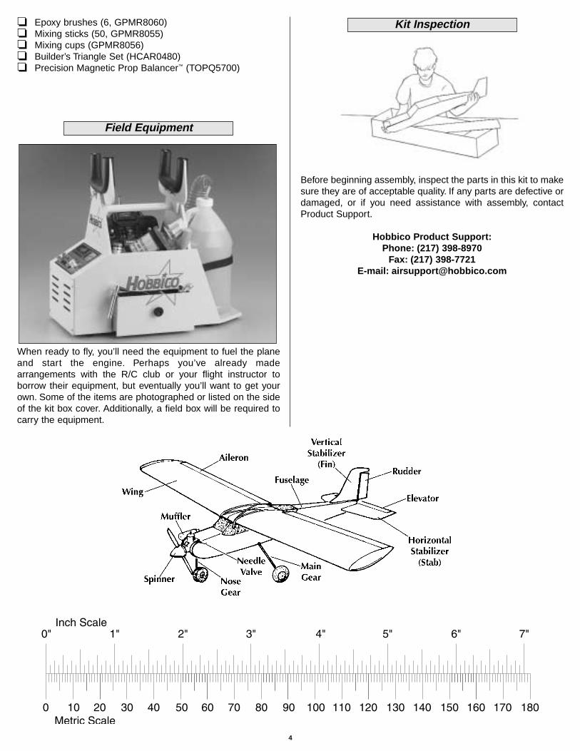
Before beginning assembly, inspect the parts in this kit to makesure they are of acceptable quality. If any parts are defective ordamaged, or if you need assistance with assembly, contactProduct Support.
Hobbico Product Support:Phone: (217) 398-8970
Fax: (217) 398-7721E-mail: [email protected]
Kit Inspection
Field Equipment
4

5
Parts List
❏ 1. Wing❏ 2. Fuselage (nose gear factory installed)❏ 3. Fin with rudder❏ 4. Stabilizer with elevator❏ 5. Main landing gear wires❏ 6. 2-3/4" main wheels❏ 7. 1/4" dowels❏ 8. Plywood aileron servo mount❏ 9. Plywood pushrod tube brace ❏ 10. Fuel tank w/hardware
❏ 11. Plywood fuselage servo tray❏ 12. Plywood wing joiners❏ 13. 2" spinner❏ 14. These parts not used❏ 15. Hardware (see detailed list below)
Hardware(2) Brass body for screw-lock pushrod
connector (throttle, nose steering)(6) 6-32 Blind nuts (factory-installed,
4-engine mount, 2-nose gear mount)(2) Nylon control horns (1-elevator,
1-rudder)(1) 5/32" Nylon nose steering arm (factory
installed)(5) Nylon clevis (2-ailerons, 1-elevator,
1-rudder)(2) Nylon landing gear straps (main
landing gear)(15) CA hinges(4) Nylon Faslinks (2-ailerons, 1-elevator,
1-rudder)(2) Nylon torque rod horns (aileron
torque rods)(2) 3/16" Gray pushrod tubes (elevator,
rudder, throttle, antenna guide)
(5) Silicone retainers (for clevises)(7) 6-32 x 1/8" Socket set screws (6-wheel
collars, 1-nose gear collar)(1) 6-32 x 1/4" Socket-head cap screw
(nose steering arm)(2) 4-40 x 1/4" Socket-head cap screws
(screw-lock pushrod connectors)(6) 6-32 x 3/4" Screws (factory-installed,
4-engine mount, 2-nose gear mount)(8) 5/32" Wheel collars (6-wheels, 1-nose
steering arm, 1-nose gear)(1) 17-1/2" Wire pushrod (throttle)(2) 36" Wire pushrods (1-elevator, 1-rudder)(2) 6" Wire pushrods (ailerons)(6) #6 Washer (factory installed, 4-engine
mount, 2-nose gear mount)(4) 2-56 x 1/2" Screw (elevator and rudder
control horns)(8) #2 x 1/2" Screw (4-main landing gear
straps, 4-servo tray)
(12) #64 Rubber bands(1) Engine mount (factory installed)(2) Metal engine mounting straps (4) 4mm Nuts (engine mounting)(4) 4mm Washers (engine mounting)(4) 4mm Lock washers (engine mounting)(4) 4 x 25mm Screws (engine mounting)(1) Nose gear mount (factory installed)
1
2
3
4
1
13
15
11
10
12
14
14
6
6
5
57 8
9

Hinge the Ailerons
Start with the right wing first.
❏ ❏ 1. Carefully remove the masking tape holding the aileronto the wing. Also remove the protective foam block on theaileron torque rod.
❏ ❏ 2. Use a hobby knife with a #11 blade to “loosen-up” theprecut hinge slots in the wing to help the hinges go in easier.This is done by inserting the blade into the hinge slot andmoving it from side-to-side several times. Note that the backedge of the blade is the part that does the work.
❏ ❏ 3. Insert a CA hinge halfway into each hinge slot in theaileron. Test fit the aileron to the wing and to the aileron torquerod with the hinges.
❏ ❏ 4. Mark the exact location of the hinges by cutting smallslits through the covering on both sides of the hinges in thewing and aileron.
❏ ❏ 5. Remove the aileron from the wing and take out thehinges. Cut a small strip of covering from the hinge slots in theaileron and the wing between the slits you cut. Hint: Use asmall metal straightedge as a cutting guide.
❏ ❏ 6. Lay a few paper towels neatly on top of each other.Use a pair of scissors to cut them into small squares. Thesepaper towel squares will come in handy throughout theassembly process (and will save you from wasting whole papertowels for small jobs).
❏ ❏ 7. Mix a small batch of 30-minute epoxy. Use a toothpickor a small piece of wire to work some epoxy into the hole andthe groove in the aileron for the torque rod. Also coat the torquerod with epoxy.
❏ ❏ 8. Join the aileron to the wing with the hinges. Be certainthat the hinges remain centered. If any hinges do not remaincentered, stick a pin through the hinge near the middle, thenrejoin the aileron to the wing. Pull out any pins you may haveused. Use a paper towel square to wipe away epoxy that hassqueezed out of the aileron.
Assemble the Wing
6

❏ ❏ 9. Position the aileron so there is a small gap betweenthe aileron and the wing–just enough to see light through or toslip a piece of paper through. Add six drops of thin CA to thetop of each hinge. Wait a few seconds between drops to allowthe CA to fully soak in so it does not get into the gap. Aftergluing the tops of all the hinges, flip the wing over and add sixdrops of CA to the bottom of each hinge. Keep the paper towelsquares close by to absorb excess CA that doesn’t get into thehinges.
❏ 10. Return to step 1 and hinge the left wing the same way.
Join the Wing Halves
❏ 1. Use epoxy to securely glue together both 1/8" [3mm]plywood wing joiners. Clamp the joiners together and wipeaway excess epoxy that squeezes out.
❏ 2. After the epoxy from the previous step has hardened, testfit the joiner in one, then the other wing half. Test join the wingswith the joiner.
❏ 3. Lay one wing panel flat on your workbench. Measure thedistance between the bottom of the raised end of the wing andthe workbench. The measurement should be 3-1/4" to 4-1/4"[80mm to 110mm].
❏ 4. Separate the wings. Cut out the sheeting so the servo cango half-way in. If necessary, enlarge the cutout in the rib so theservo will fit. Prepare the other wing half the same way.
❏ 5. Mix up 1/2 oz. [15ml] of 30-minute epoxy. Working quickly,pour a generous amount into one of the wing halves where thejoiner goes. Use a piece of stiff wire or something similar tospread the epoxy all around the inside to coat all the surfaces.Thoroughly coat one half of the joiner with epoxy as well. Insertthe coated end of the joiner into the wing. Coat the rib on theend of the wing with epoxy (an epoxy brush works well for this).
❏ 6. Use the remainder of the epoxy to coat the protruding endof the joiner and the inside of the opening in the other wing half.Join the wings and use your paper towel squares to wipe awayexcess epoxy as it squeezes out.
7
❏ 7. Tightly tape the wing halves together with several stripsof masking tape on the top and bottom. Continue to wipe awayexcess epoxy as it comes out. Be certain the front and back ofboth wings accurately align. Do not disturb the wing until theepoxy has hardened.
Hook Up the Ailerons
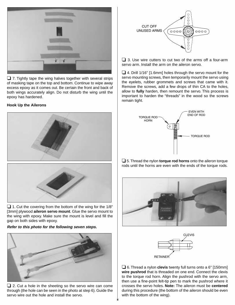
❏ 1. Cut the covering from the bottom of the wing for the 1/8"[3mm] plywood aileron servo mount. Glue the servo mount tothe wing with epoxy. Make sure the mount is level and fill thegap on both sides with epoxy.
Refer to this photo for the following seven steps.
❏ 2. Cut a hole in the sheeting so the servo wire can comethrough (the hole can be seen in the photo at step 6). Guide theservo wire out the hole and install the servo.
❏ 3. Use wire cutters to cut two of the arms off a four-armservo arm. Install the arm on the aileron servo.
❏ 4. Drill 1/16" [1.6mm] holes through the servo mount for theservo mounting screws, then temporarily mount the servo usingthe eyelets, rubber grommets and screws that came with it.Remove the screws, add a few drops of thin CA to the holes,allow to fully harden, then remount the servo. This process isimportant to harden the “threads” in the wood so the screwsremain tight.
❏ 5.Thread the nylon torque rod horns onto the aileron torquerods until the horns are even with the ends of the torque rods.
❏ 6. Thread a nylon clevis twenty full turns onto a 6" [150mm]wire pushrod that is threaded on one end. Connect the clevisto the torque rod horn. Align the pushrod with the servo arm,then use a fine-point felt-tip pen to mark the pushrod where itcrosses the servo holes. Note: The aileron must be centeredduring this procedure (the bottom of the aileron should be evenwith the bottom of the wing).
8

❏ 7. Disconnect the pushrod from the torque rod horn. Usepliers to make a 90° bend in the pushrod at the mark youmade. Fit a nylon Faslink to the pushrod, then cut off theexcess pushrod 1/16" [2mm] above the Faslink.
❏ 8. Enlarge the holes in the servo arm with a #48 or 5/64"[2mm] drill or a hobby knife. Connect the pushrod to the thirdhole out on the servo arm. Note: If using servo arms differentthan the Futaba servo arms shown in this manual, connect thepushrod to a hole that is as close as possible to 17/32" [13mm]from the center.
9. Make and connect the other pushrod the same way.
Now the wing is finished. Set it aside while working on thefuselage.
Mount the Landing Gear
❏ 1. Use a small metal file to file a 1/8" [3mm] wide “flat spot”1/8" [3mm] from the end of both main landing gear wires.
❏ 2. Mount the wheels to the landing gear with a 5/32" wheelcollar on both sides of each wheel. Add a small drop of non-permanent thread locking compound (such as Great PlanesThreadlocker GPMR6060) to two 6-32 set screws and threadthem into the collars using a 1/16" hex (“Allen”) wrench.Position the wheel collars, then tighten the set screws. Becertain the set screw in the outer wheel collar is in the flat spot.
❏ 3. Use a hobby knife with a #11 blade to round the inneredges of the holes in the landing gear rail in the bottom of thefuselage for the main landing gear. This way, the landing gearwires will go all the way down. Fuelproof the bare wood in thegroove by applying a light coat of epoxy.
#2 x 1/2" [13mm] screw
❏ 4. Insert the main landing gear wires into the holes, then drill1/16" holes for the nylon straps. Mount the gear to the bottomof the fuselage with the straps and four #2 x 1/2" [13mm] screws.
Assemble the Fuselage
9
Mount the Stab and Fin
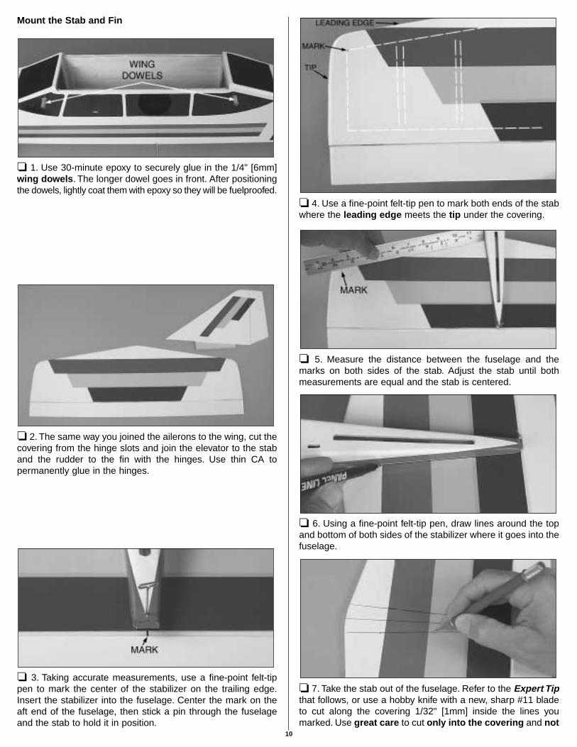
❏ 1. Use 30-minute epoxy to securely glue in the 1/4" [6mm]wing dowels. The longer dowel goes in front. After positioningthe dowels, lightly coat them with epoxy so they will be fuelproofed.
❏ 2. The same way you joined the ailerons to the wing, cut thecovering from the hinge slots and join the elevator to the staband the rudder to the fin with the hinges. Use thin CA topermanently glue in the hinges.
❏ 3. Taking accurate measurements, use a fine-point felt-tippen to mark the center of the stabilizer on the trailing edge.Insert the stabilizer into the fuselage. Center the mark on theaft end of the fuselage, then stick a pin through the fuselageand the stab to hold it in position.
❏ 4. Use a fine-point felt-tip pen to mark both ends of the stabwhere the leading edge meets the tip under the covering.
❏ 5. Measure the distance between the fuselage and themarks on both sides of the stab. Adjust the stab until bothmeasurements are equal and the stab is centered.
❏ 6. Using a fine-point felt-tip pen, draw lines around the topand bottom of both sides of the stabilizer where it goes into thefuselage.
❏ 7. Take the stab out of the fuselage. Refer to the Expert Tipthat follows, or use a hobby knife with a new, sharp #11 bladeto cut along the covering 1/32" [1mm] inside the lines youmarked. Use great care to cut only into the covering and not
10

into the balsa beneath. Cutting too deep will weaken thestructure, possibly causing the stab to break during flight.
❏ 8. Peel the covering from the stab. Use one of your papertowel squares lightly moistened with denatured alcohol to wipethe ink from the stab and the fuselage.
❏ 9. Mix 1/4 oz. of 30-minute epoxy. Apply epoxy to both sidesof the stab where it contacts the fuselage and in the fuselagewhere it contacts the stab. Slide the stab into position andcenter-it-up as you did with the pin and by takingmeasurements as in steps 3 & 5. Wipe away excess epoxy. Donot disturb the fuselage until the epoxy has hardened.
❏ 10. Test fit the fin in the fuselage. Similar to what was donefor the stab, mark the outline of the fin onto the top of thefuselage, then cut away the covering and wipe away the ink.
❏ 11. Glue the fin into the fuselage with 30-minute epoxy. Becertain to apply epoxy to both the fin and the fuselage wherethey contact each other. Immediately after inserting the fin andbefore the epoxy hardens, use a builder’s triangle to makecertain the fin is perpendicular to the stab. If it is not, usemasking tape to pull the fin to one side or the other to get itvertical.
Mount the Engine and Radio Tray
❏ 1. Mount the engine to the mount with two metal straps, four4 x 25mm screws and 4mm lock washers and 4mm nuts. Becertain the engine is pointing straight ahead, and is not slantedoff to one side or the other. Note that the lock washers go underthe heads of the screws. Be certain the engine is centered andthat the screws are evenly tightened. Do not use a small, hobbyscrewdriver to tighten the screws. A large (No. 2) Phillipsscrewdriver is preferred.
An alternate way to cut the covering over the stabilizer is touse a soldering iron. This way, you will not risk accidentallycutting into the balsa. A fine soldering tip is not necessary,but does work best. Using a metal straightedge as a guide,move the soldering iron just fast enough to melt through thecovering. Be careful not to burn the wood, otherwise you willhave defeated the purpose of using a soldering iron to cutonly the covering.
11
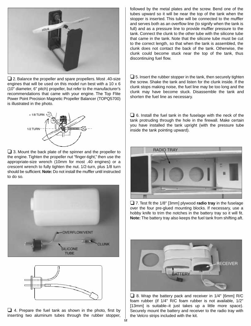
❏ 2. Balance the propeller and spare propellers. Most .40-sizeengines that will be used on this model run best with a 10 x 6(10" diameter, 6" pitch) propeller, but refer to the manufacturer’srecommendations that came with your engine. The Top FlitePower Point Precision Magnetic Propeller Balancer (TOPQ5700)is illustrated in the photo.
❏ 3. Mount the back plate of the spinner and the propeller tothe engine. Tighten the propeller nut “finger-tight,” then use theappropriate-size wrench (10mm for most .40 engines) or acrescent wrench to fully tighten the nut. 1/2-turn, plus 1/8 turnshould be sufficient. Note: Do not install the muffler until instructedto do so.
❏ 4. Prepare the fuel tank as shown in the photo, first byinserting two aluminum tubes through the rubber stopper,
followed by the metal plates and the screw. Bend one of thetubes upward so it will be near the top of the tank when thestopper is inserted. This tube will be connected to the mufflerand serves both as an overflow line (to signify when the tank isfull) and as a pressure line to provide muffler pressure to thetank. Connect the clunk to the other tube with the silicone tubethat came in the tank. Note that the silicone tube must be cutto the correct length, so that when the tank is assembled, theclunk does not contact the back of the tank. Otherwise, theclunk could become stuck near the top of the tank, thusdiscontinuing fuel flow.
❏ 5. Insert the rubber stopper in the tank, then securely tightenthe screw. Shake the tank and listen for the clunk inside. If theclunk stops making noise, the fuel line may be too long and theclunk may have become stuck. Disassemble the tank andshorten the fuel line as necessary.
❏ 6. Install the fuel tank in the fuselage with the neck of thetank protruding through the hole in the firewall. Make certainyou have installed the tank upright (with the pressure tubeinside the tank pointing upward).
❏ 7. Test fit the 1/8" [3mm] plywood radio tray in the fuselageover the four pre-glued mounting blocks. If necessary, use ahobby knife to trim the notches in the battery tray so it will fit.Note: The battery tray also keeps the fuel tank from shifting aft.
❏ 8. Wrap the battery pack and receiver in 1/4" [6mm] R/Cfoam rubber (if 1/4" R/C foam rubber is not available, 1/2"[13mm] is suitable–it just takes up a little more space).Securely mount the battery and receiver to the radio tray withthe Velcro strips included with the kit.
12
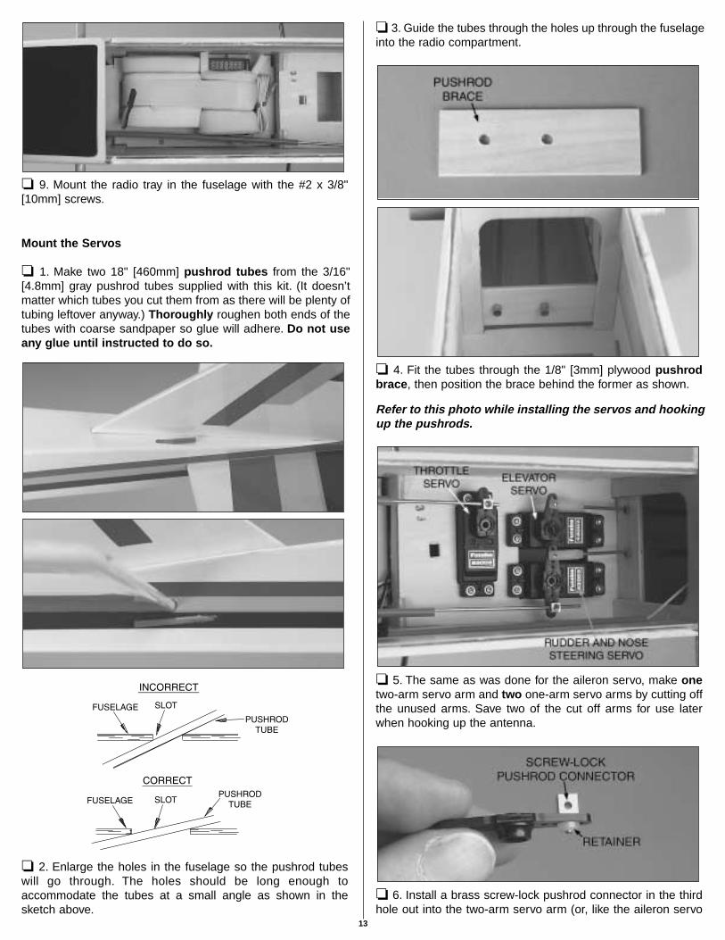
❏ 9. Mount the radio tray in the fuselage with the #2 x 3/8"[10mm] screws.
Mount the Servos
❏ 1. Make two 18" [460mm] pushrod tubes from the 3/16"[4.8mm] gray pushrod tubes supplied with this kit. (It doesn’tmatter which tubes you cut them from as there will be plenty oftubing leftover anyway.) Thoroughly roughen both ends of thetubes with coarse sandpaper so glue will adhere. Do not useany glue until instructed to do so.
❏ 2. Enlarge the holes in the fuselage so the pushrod tubeswill go through. The holes should be long enough toaccommodate the tubes at a small angle as shown in thesketch above.
❏ 3. Guide the tubes through the holes up through the fuselageinto the radio compartment.
❏ 4. Fit the tubes through the 1/8" [3mm] plywood pushrodbrace, then position the brace behind the former as shown.
Refer to this photo while installing the servos and hookingup the pushrods.
❏ 5. The same as was done for the aileron servo, make onetwo-arm servo arm and two one-arm servo arms by cutting offthe unused arms. Save two of the cut off arms for use laterwhen hooking up the antenna.
❏ 6. Install a brass screw-lock pushrod connector in the thirdhole out into the two-arm servo arm (or, like the aileron servo
13
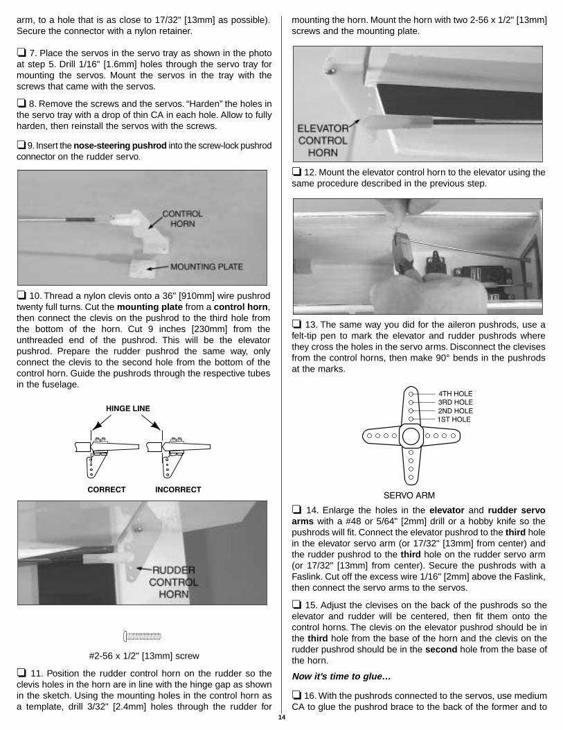
arm, to a hole that is as close to 17/32" [13mm] as possible).Secure the connector with a nylon retainer.
❏ 7. Place the servos in the servo tray as shown in the photoat step 5. Drill 1/16" [1.6mm] holes through the servo tray formounting the servos. Mount the servos in the tray with thescrews that came with the servos.
❏ 8. Remove the screws and the servos. “Harden” the holes inthe servo tray with a drop of thin CA in each hole. Allow to fullyharden, then reinstall the servos with the screws.
❏ 9. Insert the nose-steering pushrod into the screw-lock pushrodconnector on the rudder servo.
❏ 10. Thread a nylon clevis onto a 36" [910mm] wire pushrodtwenty full turns. Cut the mounting plate from a control horn,then connect the clevis on the pushrod to the third hole fromthe bottom of the horn. Cut 9 inches [230mm] from theunthreaded end of the pushrod. This will be the elevatorpushrod. Prepare the rudder pushrod the same way, onlyconnect the clevis to the second hole from the bottom of thecontrol horn. Guide the pushrods through the respective tubesin the fuselage.
#2-56 x 1/2" [13mm] screw
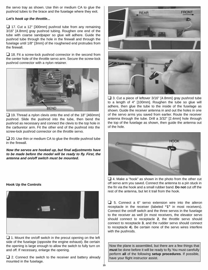
❏ 11. Position the rudder control horn on the rudder so theclevis holes in the horn are in line with the hinge gap as shownin the sketch. Using the mounting holes in the control horn asa template, drill 3/32" [2.4mm] holes through the rudder for
mounting the horn. Mount the horn with two 2-56 x 1/2" [13mm]screws and the mounting plate.
❏ 12. Mount the elevator control horn to the elevator using thesame procedure described in the previous step.
❏ 13. The same way you did for the aileron pushrods, use afelt-tip pen to mark the elevator and rudder pushrods wherethey cross the holes in the servo arms. Disconnect the clevisesfrom the control horns, then make 90° bends in the pushrodsat the marks.
❏ 14. Enlarge the holes in the elevator and rudder servoarms with a #48 or 5/64" [2mm] drill or a hobby knife so thepushrods will fit. Connect the elevator pushrod to the third holein the elevator servo arm (or 17/32" [13mm] from center) andthe rudder pushrod to the third hole on the rudder servo arm(or 17/32" [13mm] from center). Secure the pushrods with aFaslink. Cut off the excess wire 1/16" [2mm] above the Faslink,then connect the servo arms to the servos.
❏ 15. Adjust the clevises on the back of the pushrods so theelevator and rudder will be centered, then fit them onto thecontrol horns. The clevis on the elevator pushrod should be inthe third hole from the base of the horn and the clevis on therudder pushrod should be in the second hole from the base ofthe horn.
Now it’s time to glue…
❏ 16. With the pushrods connected to the servos, use mediumCA to glue the pushrod brace to the back of the former and to
14
the servo tray as shown. Use thin or medium CA to glue thepushrod tubes to the brace and the fuselage where they exit.
Let’s hook up the throttle...
❏ 17. Cut a 12" [300mm] pushrod tube from any remaining3/16" [4.8mm] gray pushrod tubing. Roughen one end of thetube with coarse sandpaper so glue will adhere. Guide thepushrod tube through the hole in the firewall and through thefuselage until 1/8" [3mm] of the roughened end protrudes fromthe firewall.
❏ 18. Fit a screw-lock pushrod connector in the second fromthe center hole of the throttle servo arm. Secure the screw-lockpushrod connector with a nylon retainer.
❏ 19. Thread a nylon clevis onto the end of the 18" [460mm]pushrod. Slide the pushrod into the tube, then bend thepushrod as necessary and connect the clevis to the top hole inthe carburetor arm. Fit the other end of the pushrod into thescrew-lock pushrod connector on the throttle servo.
❏ 20. Use thin or medium CA to glue the throttle pushrod tubein the firewall.
Now the servos are hooked up, but final adjustments haveto be made before the model will be ready to fly. First, theantenna and on/off switch must be mounted.
Hook Up the Controls
❏ 1. Mount the on/off switch in the precut opening on the leftside of the fuselage (opposite the engine exhaust). Be certainthe opening is large enough to allow the switch to fully turn onand off. If necessary, enlarge the opening.
❏ 2. Connect the switch to the receiver and battery alreadymounted in the fuselage.
❏ 3. Cut a piece of leftover 3/16" [4.8mm] gray pushrod tubeto a length of 4" [100mm]. Roughen the tube so glue willadhere, then glue the tube to the inside of the fuselage asshown. Guide the receiver antenna in and out the holes in oneof the servo arms you saved from earlier. Route the receiverantenna through the tube. Drill a 3/32" [2.4mm] hole throughthe top of the fuselage as shown, then guide the antenna outof the hole.
❏ 4. Make a “hook” as shown in the photo from the other cutoff servo arm you saved. Connect the antenna to a pin stuck inthe fin via the hook and a small rubber band. Do not cut off therest of the antenna, but let it trail from the hook.
❏ 5. Connect a 6" servo extension wire into the aileronreceptacle in the receiver (labeled “1” in most receivers).Connect the on/off switch and the three servos in the fuselageto the receiver as well (in most receivers, the elevator servoshould connect to receptacle 2, the throttle servo shouldconnect to receptacle 3, and the rudder servo should connectto receptacle 4). Be certain none of the servo wires interferewith the pushrods.
Now the plane is assembled, but there are a few things thatmust be done before it will be ready to fly.You must carefullyperform all of the following setup procedures. If possible,have your flight instructor assist.
15

The batteries must be charged to continue.
Check the Control Directions
The first thing that has to be done is to center the controlsand make sure they all move in the right direction.
❏ 1. Connect the aileron servo wire coming from the wing tothe servo wire coming from the receiver. Temporarily place thewing on the fuselage.
❏ 2. Center all the trims on the transmitter. Turn on thetransmitter, then the receiver. (The idea is to never have thereceiver on by itself. When turning off the system, turn off thereceiver first, then the transmitter.)
❏ 3. Observe the servo arms on all the servos. If necessary,take the servo arms off any servos that are not centered andreposition them so they are centered. Be certain to reinstall andtighten any screws you may have removed from the servo arms.
❏ 4. Move the right control stick on the transmitter to the rightas shown in the diagram. Observe the ailerons. The rightaileron should move up and the left aileron should move down.Moving the control stick to the left should make the aileronsmove the opposite way. If the ailerons do not respond asdescribed, reverse the direction using the reversing switch forthe ailerons on the transmitter. If necessary, refer to theinstructions in the manual that came with your radio to identifyand operate the reversing switch.
❏ 5. Move the right stick down (pull it back) to make theelevator go up. Move the left stick to the right to make therudder (and nose wheel) move right. Move the left stick downto close the throttle. If necessary, use the reversing switches onthe transmitter to make the controls respond in the correctdirection.
Prepare the Model for Flight
16
Set the Control Throws
The next thing that has to be done is to make sure thecontrols move the correct amount.
The control throws are a measure of how far the flight controls(ailerons, elevator and rudder) move. If the controls move toomuch, the plane will respond too quickly and be difficult tocontrol. If the controls do not move enough, it may not bepossible to recover the plane from adverse situations or to flarefor landing. Due to the great effect the control throws have onthe way a model flies, the control throws must be checked andcorrected if necessary.
❏ 1. Turn on the transmitter and receiver. Center all the trimlevers on the transmitter.
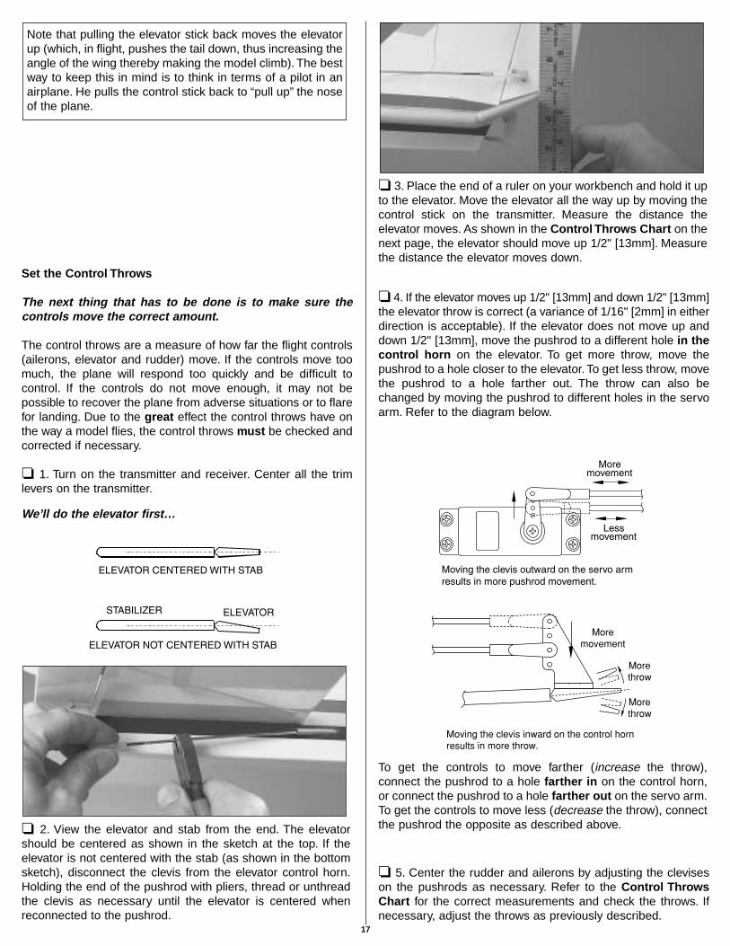
We’ll do the elevator first…
❏ 2. View the elevator and stab from the end. The elevatorshould be centered as shown in the sketch at the top. If theelevator is not centered with the stab (as shown in the bottomsketch), disconnect the clevis from the elevator control horn.Holding the end of the pushrod with pliers, thread or unthreadthe clevis as necessary until the elevator is centered whenreconnected to the pushrod.
❏ 3. Place the end of a ruler on your workbench and hold it upto the elevator. Move the elevator all the way up by moving thecontrol stick on the transmitter. Measure the distance theelevator moves. As shown in the Control Throws Chart on thenext page, the elevator should move up 1/2" [13mm]. Measurethe distance the elevator moves down.
❏ 4. If the elevator moves up 1/2" [13mm] and down 1/2" [13mm]the elevator throw is correct (a variance of 1/16" [2mm] in eitherdirection is acceptable). If the elevator does not move up anddown 1/2" [13mm], move the pushrod to a different hole in thecontrol horn on the elevator. To get more throw, move thepushrod to a hole closer to the elevator. To get less throw, movethe pushrod to a hole farther out. The throw can also bechanged by moving the pushrod to different holes in the servoarm. Refer to the diagram below.
To get the controls to move farther (increase the throw),connect the pushrod to a hole farther in on the control horn,or connect the pushrod to a hole farther out on the servo arm.To get the controls to move less (decrease the throw), connectthe pushrod the opposite as described above.
❏ 5. Center the rudder and ailerons by adjusting the cleviseson the pushrods as necessary. Refer to the Control ThrowsChart for the correct measurements and check the throws. Ifnecessary, adjust the throws as previously described.
Note that pulling the elevator stick back moves the elevatorup (which, in flight, pushes the tail down, thus increasing theangle of the wing thereby making the model climb). The bestway to keep this in mind is to think in terms of a pilot in anairplane. He pulls the control stick back to “pull up” the noseof the plane.
17
❏ 6. Center the nose wheel. Insert and tighten a 4-40 x 1/4"[6mm] screw in the screw-lock pushrod connector previouslyinstalled in the rudder servo arm. Roll the model on the floor tomake sure it goes straight. If necessary, loosen the screw in thescrew-lock pushrod connector and readjust the pushrod.
Adjust the Throttle
The throttle is to be set up so that when the throttle stick is allthe way down, and the throttle trim lever is all the way up, thecarburetor will be nearly, but not fully closed and the engine willidle at a low RPM. This will keep the engine running when thethrottle stick is pulled all the way down (toward you) for landing.When, after landing, it is time to shut the engine off, move thetrim lever down to fully close the carburetor.
Here’s how to set up the carburetor…
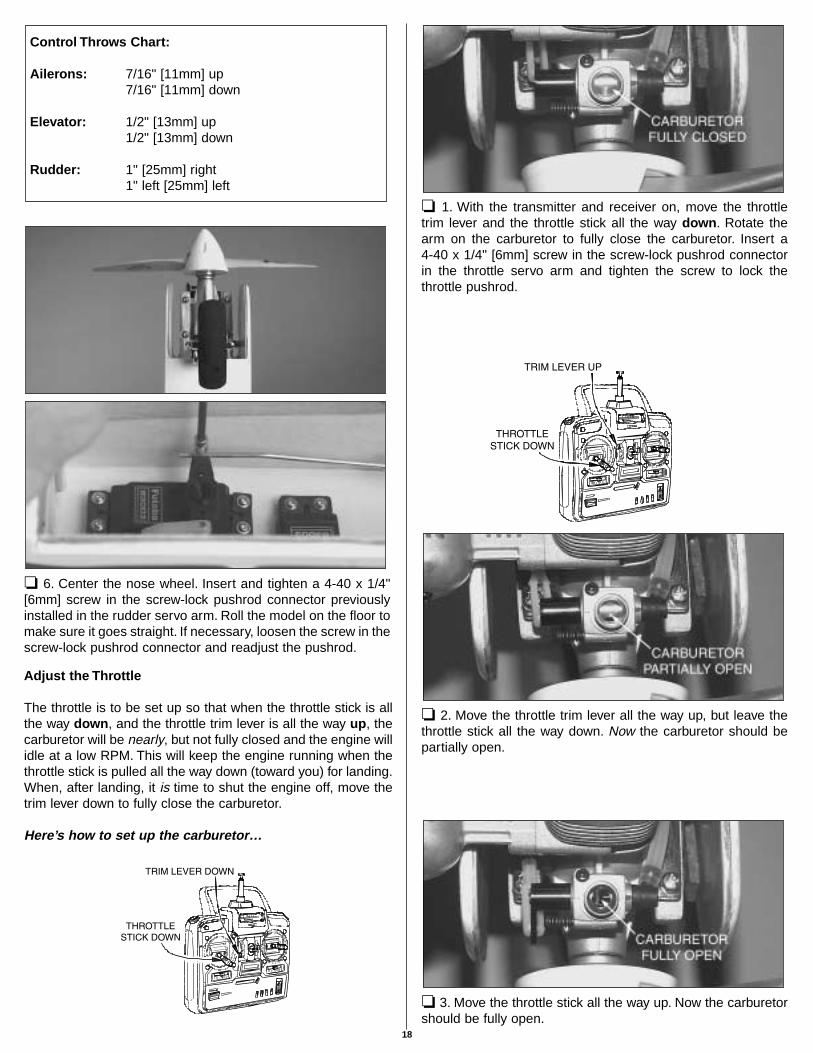
❏ 1. With the transmitter and receiver on, move the throttletrim lever and the throttle stick all the way down. Rotate thearm on the carburetor to fully close the carburetor. Insert a 4-40 x 1/4" [6mm] screw in the screw-lock pushrod connectorin the throttle servo arm and tighten the screw to lock thethrottle pushrod.
❏ 2. Move the throttle trim lever all the way up, but leave thethrottle stick all the way down. Now the carburetor should bepartially open.
❏ 3. Move the throttle stick all the way up. Now the carburetorshould be fully open.
Control Throws Chart:
Ailerons: 7/16" [11mm] up7/16" [11mm] down
Elevator: 1/2" [13mm] up1/2" [13mm] down
Rudder: 1" [25mm] right1" left [25mm] left
18
❏ 4. If you are not able to achieve these settings, more or lessmovement may be required from the throttle pushrod. Thesame as the control surface throws, this is done by relocatingthe screw-lock pushrod connector on the servo arm to anotherhole, or by relocating the clevis on the carburetor arm to theother hole.
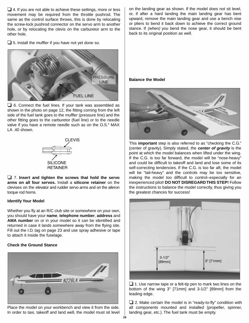
❏ 5. Install the muffler if you have not yet done so.
❏ 6. Connect the fuel lines. If your tank was assembled asshown in the photo on page 12, the fitting coming from the leftside of the fuel tank goes to the muffler (pressure line) and theother fitting goes to the carburetor (fuel line) or to the needlevalve if you have a remote needle such as on the O.S.® MAXLA .40 shown.
❏ 7. Insert and tighten the screws that hold the servoarms on all four servos. Install a silicone retainer on theclevises on the elevator and rudder servo arms and on the ailerontorque rod horns.
Identify Your Model
Whether you fly at an R/C club site or somewhere on your own,you should have your name, telephone number, address andAMA number on or in your model so it can be identified andreturned in case it lands somewhere away from the flying site.Fill out the I.D. tag on page 23 and use spray adhesive or tapeto attach it inside the fuselage.
Check the Ground Stance
Place the model on your workbench and view it from the side.In order to taxi, takeoff and land well, the model must sit level
on the landing gear as shown. If the model does not sit level,or, if after a hard landing the main landing gear has bentupward, remove the main landing gear and use a bench viseor pliers to bend it back down to achieve the correct groundstance. If (when) you bend the nose gear, it should be bentback to its original position as well.
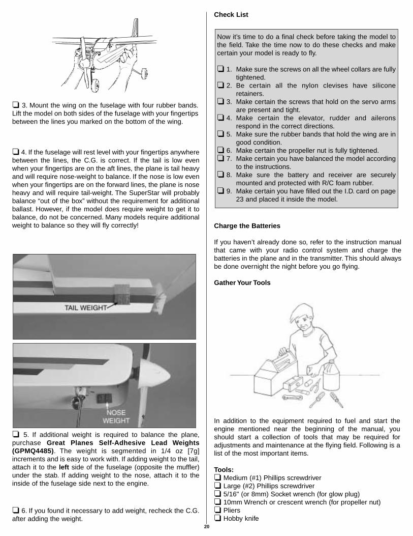
Balance the Model
This important step is also referred to as “checking the C.G.”(center of gravity). Simply stated, the center of gravity is thepoint at which the model balances when lifted under the wing.If the C.G. is too far forward, the model will be “nose-heavy”and could be difficult to takeoff and land and lose some of itsself-correcting tendencies. If the C.G. is too far aft, the modelwill be “tail-heavy” and the controls may be too sensitive,making the model too difficult to control–especially for aninexperienced pilot! DO NOT DISREGARD THIS STEP! Followthe instructions to balance the model correctly, thus giving youthe greatest chances for success!
❏ 1. Use narrow tape or a felt-tip pen to mark two lines on thebottom of the wing 3" [71mm] and 3-1/2" [89mm] from theleading edge.
❏ 2. Make certain the model is in “ready-to-fly” condition withall components mounted and installed (propeller, spinner,landing gear, etc.). The fuel tank must be empty.
19
❏ 3. Mount the wing on the fuselage with four rubber bands.Lift the model on both sides of the fuselage with your fingertipsbetween the lines you marked on the bottom of the wing.
❏ 4. If the fuselage will rest level with your fingertips anywherebetween the lines, the C.G. is correct. If the tail is low evenwhen your fingertips are on the aft lines, the plane is tail heavyand will require nose-weight to balance. If the nose is low evenwhen your fingertips are on the forward lines, the plane is noseheavy and will require tail-weight. The SuperStar will probablybalance “out of the box” without the requirement for additionalballast. However, if the model does require weight to get it tobalance, do not be concerned. Many models require additionalweight to balance so they will fly correctly!
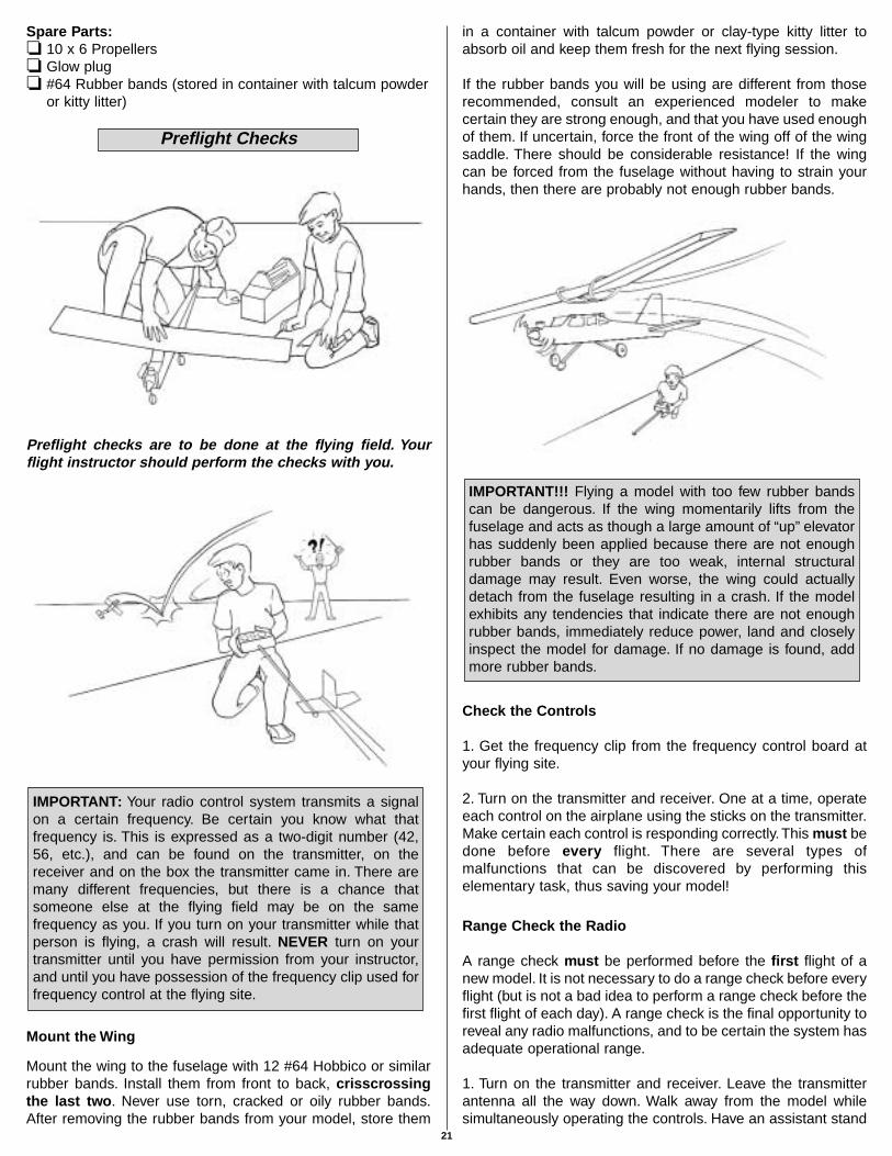
❏ 5. If additional weight is required to balance the plane,purchase Great Planes Self-Adhesive Lead Weights(GPMQ4485). The weight is segmented in 1/4 oz [7g]increments and is easy to work with. If adding weight to the tail,attach it to the left side of the fuselage (opposite the muffler)under the stab. If adding weight to the nose, attach it to theinside of the fuselage side next to the engine.
❏ 6. If you found it necessary to add weight, recheck the C.G.after adding the weight.
Check List
Charge the Batteries
If you haven’t already done so, refer to the instruction manualthat came with your radio control system and charge thebatteries in the plane and in the transmitter. This should alwaysbe done overnight the night before you go flying.
Gather Your Tools
In addition to the equipment required to fuel and start theengine mentioned near the beginning of the manual, youshould start a collection of tools that may be required foradjustments and maintenance at the flying field. Following is alist of the most important items.
Tools:❏ Medium (#1) Phillips screwdriver❏ Large (#2) Phillips screwdriver❏ 5/16" (or 8mm) Socket wrench (for glow plug)❏ 10mm Wrench or crescent wrench (for propeller nut)❏ Pliers❏ Hobby knife
Now it’s time to do a final check before taking the model tothe field. Take the time now to do these checks and makecertain your model is ready to fly.
❏ 1. Make sure the screws on all the wheel collars are fullytightened.
❏ 2. Be certain all the nylon clevises have siliconeretainers.
❏ 3. Make certain the screws that hold on the servo armsare present and tight.
❏ 4. Make certain the elevator, rudder and aileronsrespond in the correct directions.
❏ 5. Make sure the rubber bands that hold the wing are ingood condition.
❏ 6. Make certain the propeller nut is fully tightened.❏ 7. Make certain you have balanced the model according
to the instructions.❏ 8. Make sure the battery and receiver are securely
mounted and protected with R/C foam rubber.❏ 9. Make certain you have filled out the I.D. card on page
23 and placed it inside the model.
20
Spare Parts:❏ 10 x 6 Propellers❏ Glow plug❏ #64 Rubber bands (stored in container with talcum powder
or kitty litter)
Preflight checks are to be done at the flying field. Yourflight instructor should perform the checks with you.
Mount the Wing
Mount the wing to the fuselage with 12 #64 Hobbico or similarrubber bands. Install them from front to back, crisscrossingthe last two. Never use torn, cracked or oily rubber bands.After removing the rubber bands from your model, store them
in a container with talcum powder or clay-type kitty litter toabsorb oil and keep them fresh for the next flying session.
If the rubber bands you will be using are different from thoserecommended, consult an experienced modeler to makecertain they are strong enough, and that you have used enoughof them. If uncertain, force the front of the wing off of the wingsaddle. There should be considerable resistance! If the wingcan be forced from the fuselage without having to strain yourhands, then there are probably not enough rubber bands.
Check the Controls
1. Get the frequency clip from the frequency control board atyour flying site.
2. Turn on the transmitter and receiver. One at a time, operateeach control on the airplane using the sticks on the transmitter.Make certain each control is responding correctly.This must bedone before every flight. There are several types ofmalfunctions that can be discovered by performing thiselementary task, thus saving your model!
Range Check the Radio
A range check must be performed before the first flight of anew model. It is not necessary to do a range check before everyflight (but is not a bad idea to perform a range check before thefirst flight of each day). A range check is the final opportunity toreveal any radio malfunctions, and to be certain the system hasadequate operational range.
1. Turn on the transmitter and receiver. Leave the transmitterantenna all the way down. Walk away from the model whilesimultaneously operating the controls. Have an assistant stand
IMPORTANT!!! Flying a model with too few rubber bandscan be dangerous. If the wing momentarily lifts from thefuselage and acts as though a large amount of “up” elevatorhas suddenly been applied because there are not enoughrubber bands or they are too weak, internal structuraldamage may result. Even worse, the wing could actuallydetach from the fuselage resulting in a crash. If the modelexhibits any tendencies that indicate there are not enoughrubber bands, immediately reduce power, land and closelyinspect the model for damage. If no damage is found, addmore rubber bands.
IMPORTANT: Your radio control system transmits a signalon a certain frequency. Be certain you know what thatfrequency is. This is expressed as a two-digit number (42,56, etc.), and can be found on the transmitter, on thereceiver and on the box the transmitter came in. There aremany different frequencies, but there is a chance thatsomeone else at the flying field may be on the samefrequency as you. If you turn on your transmitter while thatperson is flying, a crash will result. NEVER turn on yourtransmitter until you have permission from your instructor,and until you have possession of the frequency clip used forfrequency control at the flying site.
Preflight Checks
21

by the model and tell you what the controls are doing to confirmthat they operate correctly. You should be able to walkapproximately 100 feet from the model and still have controlwithout any “glitching” or inadvertent servo operation.
2. If everything operates correctly, return to the model and startthe engine. Perform the range check with your assistant holdingthe plane with the engine running at various speeds. If theservos chatter or move inadvertently, there may be a problem.Do not fly the plane! With the assistance of your instructor,look for loose servo connections or binding pushrods. Also becertain you are the only one on your frequency, and that thebattery has been fully charged.
Keep all engine fuel in a safe place, away from high heat,sparks or flames, as fuel is very flammable. Do not smoke nearthe engine or fuel; and remember that engine exhaust gives offa great deal of deadly carbon monoxide. Therefore, do not runthe engine in a closed room or garage.
Get help from an experienced pilot when learning to operateengines.
Use safety glasses when starting or running engines.
Do not run the engine in an area of loose gravel or sand; thepropeller may throw such material in your face or eyes.
Keep your face and body as well as all spectators away fromthe plane of rotation of the propeller as you start and run theengine.
Keep these items away from the prop: loose clothing, shirtsleeves, ties, scarfs, long hair or loose objects such as pencilsor screwdrivers that may fall out of shirt or jacket pockets intothe prop.
Use a “chicken stick” or electric starter to start the engine. Donot use your fingers to flip the propeller. Make certain the glowplug clip or connector is secure so that it will not pop off orotherwise get into the running propeller.
Make all engine adjustments from behind the rotating propeller.
The engine gets hot! Do not touch it during or right afteroperation. Make sure fuel lines are in good condition so fuel willnot leak onto a hot engine, causing a fire.
To stop a glow engine, cut off the fuel supply by closing off thefuel line or following the engine manufacturer’s recommendations.Do not use hands, fingers or any other body part to try tostop the engine. Do not throw anything into the propeller of arunning engine.
The following flying instructions are in no way an endorsementfor learning to fly on your own, but are printed so you can knowwhat to expect and what to concentrate on while learning underthe tutelage of your instructor. Further, these flight instructionsmay be referenced once you begin flying on your own.
Taxiing
Remember, it is assumed that your instructor is operatingthe model for you.
TakeoffIf possible, takeoff directly into the wind. If you are experienced,taking off in a crosswind is permissible (and sometimesnecessary–depending upon the prevailing wind conditions andrunway heading).Taking off into the wind will help the model rollstraight and also reduces ground speed for takeoff. Taxi themodel onto the runway or have an assistant carry it out and setit down pointing down the runway into the wind. When ready,gradually advance the throttle while simultaneously using theleft stick (rudder/nose wheel) to steer the model. Gain as muchspeed as the runway and flying site will practically allow beforegently applying up elevator, lifting the model into the air. Beready to make immediate corrections with the ailerons to keepthe wings level, and be smooth on the elevator stick, allowingthe model to establish a gentle climb to a safe altitude beforemaking the first turn (away from yourself). Do not “yank” backthe elevator stick forcing the plane into too steep of a climbwhich could cause the model to stall and quit flying.
Flight Once airborne, maintain a steady climb and make the initialturn away from the runway. When at a comfortable, safe altitude
IMPORTANT: If you do insist on flying on your own, youmust be aware of your proximity to R/C club sites. If there isan R/C site within six miles of where you are flying, and ifyou are operating your model on the same frequency at thesame time as somebody else, there is a strong possibilitythat one or both models will crash due to radio interference.There is great potential for an out-of-control model to causeproperty damage and/or severe personal injury. Westrongly urge you to fly at a R/C club site where frequencycontrol is in effect so you can be assured you will be the onlyone flying on your channel.
Flying
Failure to follow these safety precautions may result insevere injury to yourself and others.
Engine Safety Precautions
22

throttle back to slow the model, thus giving you time to thinkand react. The SuperStar should fly well at half or slightly lessthan half-throttle. Adjust the trims so the plane flies straight andlevel. After flying around for a while, and while still at a safealtitude with plenty of fuel, practice slow flight and executepractice landing approaches by reducing the throttle further tosee how the model handles when coming in to land. Add powerto see how the model climbs as well. Continue to fly aroundwhile learning how the model responds. Mind your fuel level,but use this first flight to become familiar with the model beforelanding.
Landing
When ready to land, pull the throttle stick fully back while flyingdownwind just before making the 180° turn toward the runway.Allow the nose of the model to pitch downward to graduallybleed off altitude. Continue to lose altitude, but maintainairspeed by keeping the nose down while turning. Apply upelevator to level the plane when it reaches the end of therunway and is about five to ten feet off the ground. If the modelis too far away, carefully add a small amount of power to fly themodel closer. If going too fast, smoothly advance the throttleand allow the model to gain airspeed, then apply elevator toclimb-out and go around to make another attempt. When finallyready to touch down, continue to apply up elevator, but not somuch that the airplane will climb. Continue to apply up elevatorwhile the plane descends until it gently touches down.
After you have landed and shut the engine off, adjust thepushrods on the ailerons, elevator and rudder as necessary sothe trim levers on the transmitter may be returned to center (thiswill not be required on any of the controls that did not need trimadjustments).
Maintenance Tips
1. After flying for the day, use your fuel pump to drain excessfuel from the tank.
2. Purchase spare #64 rubber bands for the wing (HCAQ2020,1/4 lb box). Do not reuse torn or oily rubber bands. After flying,remove the oily rubber bands from the wing and store them ina container with talcum powder or kitty litter. This will absorb oiland keep the rubber bands fresh for the next flying session.
3. After each day’s flying (and between flights if you like), usespray cleaner and paper towels to thoroughly clean the model.
4. The SuperStar .40 ARF is factory-covered with Top Flite®
MonoKote®. Should repairs ever be required, the covering canbe repaired with patches cut from matching MonoKote colors.MonoKote is packaged in six-foot rolls, but some hobby shopsalso sell it by the foot. If only a small piece of covering isneeded for a minor patch, perhaps a fellow modeler would giveyou some. The covering is applied with a model airplanecovering iron, but in an emergency a regular iron could be usedif set to a low heat.
Ordering Replacement Parts
To order replacement parts for the SuperStar .40 ARF, use theorder numbers in the Replacement Parts List that follows.Replacement parts are available only as listed. Not all parts areavailable separately (an aileron cannot be purchasedseparately, but is only available with the wing kit). Replacementparts are not available from Product Support, but can bepurchased from hobby shops or mail order/Internet order firms.Hardware items (screws, nuts, bolts) are also available fromthese outlets. If you need assistance locating a dealer topurchase parts, visit www.greatplanes.com and click on“Where to Buy.” If this kit is missing parts, contact HobbicoProduct Support.
Replacement Parts List
Order # Description How to PurchaseMissing Pieces Contact Product SupportInstruction Manual Contact Product SupportPlans Not available
HCAA3080 Wing SetHCAA3081 Fuse SetHCAA3083 Landing Gear SetHCAA3082 Tail Set
23
Contact your hobbysupplier to purchasethese items

BUILDING NOTES
Kit Purchased Date: _______________________
Where Purchased:_________________________
Date Construction Started: __________________
Date Construction Finished: _________________
Finished Weight: __________________________
Date of First Flight: ________________________
FLIGHT LOG